Weather radar enabled low visibility operation system and method
Jinkins , et al.
U.S. patent number 10,228,460 [Application Number 15/166,191] was granted by the patent office on 2019-03-12 for weather radar enabled low visibility operation system and method. This patent grant is currently assigned to ROCKWELL COLLINS, INC.. The grantee listed for this patent is Rockwell Collins, Inc.. Invention is credited to Richard D. Jinkins, Richard M. Rademaker.


| United States Patent | 10,228,460 |
| Jinkins , et al. | March 12, 2019 |
Weather radar enabled low visibility operation system and method
Abstract
A weather radar system can be used as an enhanced vision sensor for providing an image on an electronic display during aircraft surface operations. The weather radar sensed image is representative of the external surroundings of the airport surface environment associated with radar returns received by the weather radar system. The radar returns are processed as a collection of radar measurements to determine a high resolution angle and range to a target, using beam sharpening techniques. When the radar image is combined with an image generated from an airport surface database, the combination or comparison of the two independently created images can be used to confirm the integrity of the positioning and attitude source along with the accuracy of the airport surface database.
| Inventors: | Jinkins; Richard D. (Rewey, WI), Rademaker; Richard M. (Rijswijk, NL) | ||||||||||
|---|---|---|---|---|---|---|---|---|---|---|---|
| Applicant: |
|
||||||||||
| Assignee: | ROCKWELL COLLINS, INC. (Cedar
Rapids, IA) |
||||||||||
| Family ID: | 65633027 | ||||||||||
| Appl. No.: | 15/166,191 | ||||||||||
| Filed: | May 26, 2016 |
| Current U.S. Class: | 1/1 |
| Current CPC Class: | G01S 7/24 (20130101); G01S 13/953 (20130101) |
| Current International Class: | G01S 13/95 (20060101); G01S 7/24 (20060101); G01S 13/00 (20060101) |
References Cited [Referenced By]
U.S. Patent Documents
| 2416155 | February 1947 | Chubb |
| 2849184 | August 1958 | Arden et al. |
| 2929059 | March 1960 | Parker |
| 2930035 | March 1960 | Altekruse |
| 2948892 | August 1960 | White |
| 2965894 | December 1960 | Sweeney |
| 2994966 | August 1961 | Senitsky et al. |
| 3031660 | April 1962 | Young |
| 3049702 | August 1962 | Schreitmueller |
| 3064252 | November 1962 | Varela |
| 3070795 | December 1962 | Chambers |
| 3071766 | January 1963 | Fenn |
| 3072903 | January 1963 | Meyer |
| 3089801 | May 1963 | Tierney et al. |
| 3107351 | October 1963 | Milam |
| 3113310 | December 1963 | Standing |
| 3129425 | April 1964 | Sanner |
| 3153234 | October 1964 | Begeman et al. |
| 3175215 | March 1965 | Blasberg et al. |
| 3212088 | October 1965 | Alexander et al. |
| 3221328 | November 1965 | Walter |
| 3241141 | March 1966 | Wall |
| 3274593 | September 1966 | Varela et al. |
| 3325807 | June 1967 | Burns et al. |
| 3334344 | August 1967 | Colby, Jr. |
| 3339199 | August 1967 | Pichafroy |
| 3373423 | March 1968 | Levy |
| 3396391 | August 1968 | Anderson et al. |
| 3397397 | August 1968 | Barney |
| 3448450 | June 1969 | Alfandari et al. |
| 3618090 | November 1971 | Garrison |
| 3680094 | July 1972 | Bayle et al. |
| 3716855 | February 1973 | Asam |
| 3739380 | June 1973 | Burdic et al. |
| 3781878 | December 1973 | Kirkpatrick |
| 3810175 | May 1974 | Bell |
| 3815132 | June 1974 | Case et al. |
| 3816718 | June 1974 | Hall et al. |
| 3851758 | December 1974 | Makhijani et al. |
| 3866222 | February 1975 | Young |
| 3885237 | May 1975 | Kirkpatrick |
| 3956749 | May 1976 | Magorian |
| 4024537 | May 1977 | Hart |
| 4058701 | November 1977 | Gruber et al. |
| 4058710 | November 1977 | Altmann |
| 4063218 | December 1977 | Basov et al. |
| 4103300 | July 1978 | Gendreu et al. |
| 4235951 | November 1980 | Swarovski |
| 4277845 | July 1981 | Smith et al. |
| 4405986 | September 1983 | Gray |
| 4435707 | March 1984 | Clark |
| 4481519 | November 1984 | Margerum |
| 4509048 | April 1985 | Jain |
| 4532515 | July 1985 | Cantrell et al. |
| 4594676 | June 1986 | Breiholz et al. |
| 4595925 | June 1986 | Hansen |
| 4598292 | July 1986 | Devino |
| 4628318 | December 1986 | Alitz |
| 4646244 | February 1987 | Bateman et al. |
| 4649388 | March 1987 | Atlas |
| 4654665 | March 1987 | Kiuchi et al. |
| 4685149 | August 1987 | Smith et al. |
| 4723124 | February 1988 | Boles |
| 4760396 | July 1988 | Barney et al. |
| 4828382 | May 1989 | Vermilion |
| 4843398 | June 1989 | Houston et al. |
| 4912477 | March 1990 | Lory et al. |
| 4914436 | April 1990 | Bateman et al. |
| 4924401 | May 1990 | Bice et al. |
| 4939513 | July 1990 | Paterson et al. |
| 4951059 | August 1990 | Taylor, Jr. |
| 4953972 | September 1990 | Zuk |
| 4965573 | October 1990 | Gallagher et al. |
| 4987419 | January 1991 | Salkeld |
| 5045855 | September 1991 | Moreira |
| 5047779 | September 1991 | Hager |
| 5047781 | September 1991 | Bleakney |
| 5049886 | September 1991 | Seitz et al. |
| 5053778 | October 1991 | Imhoff |
| 5166688 | November 1992 | Moreira |
| 5173703 | December 1992 | Mangiapane et al. |
| 5175554 | December 1992 | Mangiapane et al. |
| 5198819 | March 1993 | Susnjara |
| 5202690 | April 1993 | Frederick |
| 5247303 | September 1993 | Cornelius et al. |
| 5273553 | December 1993 | Hoshi et al. |
| 5311183 | May 1994 | Mathews et al. |
| 5329391 | July 1994 | Miyamoto et al. |
| 5332998 | July 1994 | Avignon et al. |
| 5345241 | September 1994 | Huddle |
| 5365356 | November 1994 | McFadden |
| 5383457 | January 1995 | Cohen |
| 5442364 | August 1995 | Lee et al. |
| 5530440 | June 1996 | Danzer et al. |
| 5539409 | July 1996 | Mathews et al. |
| 5559515 | September 1996 | Alimena et al. |
| 5559518 | September 1996 | Didomizio |
| 5566840 | October 1996 | Waldner et al. |
| 5592178 | January 1997 | Chang et al. |
| 5678303 | October 1997 | Wichmann |
| 5736957 | April 1998 | Raney |
| 5820080 | October 1998 | Eschenbach |
| 5828332 | October 1998 | Frederick |
| 5831570 | November 1998 | Ammar et al. |
| 5839080 | November 1998 | Muller et al. |
| 5867119 | February 1999 | Corrubia et al. |
| 5894286 | April 1999 | Morand et al. |
| 5918517 | July 1999 | Malapert et al. |
| 5920276 | July 1999 | Frederick |
| 5923279 | July 1999 | Bamler et al. |
| 5936575 | August 1999 | Azzarelli et al. |
| 5942062 | August 1999 | Hassall et al. |
| 5945926 | August 1999 | Ammar et al. |
| 5950512 | September 1999 | Fields |
| 5959762 | September 1999 | Bandettini et al. |
| 5978715 | November 1999 | Briffe et al. |
| 6002347 | December 1999 | Daly et al. |
| 6023240 | February 2000 | Sutton |
| 6061016 | May 2000 | Lupinski et al. |
| 6061022 | May 2000 | Menegozzi et al. |
| 6064942 | May 2000 | Johnson et al. |
| 6075484 | June 2000 | Daniel et al. |
| 6092009 | July 2000 | Glover |
| 6112141 | August 2000 | Briffe et al. |
| 6112570 | September 2000 | Hruschak |
| 6122570 | September 2000 | Muller et al. |
| 6127944 | October 2000 | Daly et al. |
| 6128066 | October 2000 | Yokozeki |
| 6128553 | October 2000 | Gordon et al. |
| 6138060 | October 2000 | Conner et al. |
| 6150901 | November 2000 | Auken |
| 6154151 | November 2000 | McElreath et al. |
| 6154169 | November 2000 | Kuntman |
| 6157339 | December 2000 | Sato et al. |
| 6157891 | December 2000 | Lin |
| 6163021 | December 2000 | Mickelson |
| 6166661 | December 2000 | Anderson et al. |
| 6169770 | January 2001 | Henely |
| 6178391 | January 2001 | Anderson et al. |
| 6184816 | February 2001 | Zheng et al. |
| 6188330 | February 2001 | Glover |
| 6194980 | February 2001 | Thon |
| 6199008 | March 2001 | Aratow et al. |
| 6201494 | March 2001 | Kronfeld |
| 6204806 | March 2001 | Hoech |
| 6205400 | March 2001 | Lin |
| 6208284 | March 2001 | Woodell et al. |
| 6219592 | April 2001 | Muller et al. |
| 6233522 | May 2001 | Morici |
| 6236351 | May 2001 | Conner et al. |
| 6259400 | July 2001 | Higgins et al. |
| 6266114 | July 2001 | Skarohlid |
| 6278799 | August 2001 | Hoffman |
| 6281832 | August 2001 | McElreath |
| 6285298 | September 2001 | Gordon |
| 6285337 | September 2001 | West et al. |
| 6285926 | September 2001 | Weiler et al. |
| 6289277 | September 2001 | Feyereisen et al. |
| 6311108 | October 2001 | Ammar et al. |
| 6317468 | November 2001 | Meyer |
| 6317690 | November 2001 | Gia |
| 6317872 | November 2001 | Gee et al. |
| 6340946 | January 2002 | Wolfson et al. |
| 6345127 | February 2002 | Mitchell |
| 6359585 | March 2002 | Bechman et al. |
| 6366013 | April 2002 | Leenders et al. |
| 6373418 | April 2002 | Abbey |
| 6374286 | April 2002 | Gee et al. |
| 6377202 | April 2002 | Kropfli et al. |
| 6377892 | April 2002 | Johnson et al. |
| 6388607 | May 2002 | Woodell |
| 6388608 | May 2002 | Woodell et al. |
| 6388724 | May 2002 | Campbell et al. |
| 6389354 | May 2002 | Hicks et al. |
| 6401038 | June 2002 | Gia |
| 6411890 | June 2002 | Zimmerman |
| 6421000 | July 2002 | McDowell |
| 6421603 | July 2002 | Pratt et al. |
| 6424288 | July 2002 | Woodell |
| 6426717 | July 2002 | Maloratsky |
| 6426720 | July 2002 | Ross et al. |
| 6427122 | July 2002 | Lin |
| 6441773 | August 2002 | Kelly et al. |
| 6445310 | September 2002 | Bateman et al. |
| 6448922 | September 2002 | Kelly |
| 6452511 | September 2002 | Kelly et al. |
| 6456236 | September 2002 | Hauck et al. |
| 6456238 | September 2002 | Posey |
| 6462703 | October 2002 | Hedrick |
| 6473026 | October 2002 | Ali-Mehenni et al. |
| 6473037 | October 2002 | Vail et al. |
| 6473240 | October 2002 | Dehmlow |
| 6481482 | November 2002 | Shimotomai |
| 6492934 | December 2002 | Hwang et al. |
| 6501424 | December 2002 | Haendel et al. |
| 6512476 | January 2003 | Woodell |
| 6512527 | January 2003 | Barber et al. |
| 6516272 | February 2003 | Lin |
| 6516283 | February 2003 | McCall et al. |
| 6520056 | February 2003 | Nemeth et al. |
| 6525674 | February 2003 | Kelly et al. |
| 6531669 | March 2003 | Miller et al. |
| 6549161 | April 2003 | Woodell |
| 6567728 | May 2003 | Kelly et al. |
| 6574030 | June 2003 | Mosier |
| 6577947 | June 2003 | Kronfeld et al. |
| 6590528 | July 2003 | Dewulf |
| 6591171 | July 2003 | Ammar et al. |
| 6593875 | July 2003 | Bergin et al. |
| 6600443 | July 2003 | Landt |
| 6603425 | August 2003 | Woodell |
| 6614057 | September 2003 | Silvernail et al. |
| 6650275 | November 2003 | Kelly et al. |
| 6650291 | November 2003 | West et al. |
| 6653947 | November 2003 | Dwyer et al. |
| 6667710 | December 2003 | Cornell et al. |
| 6681668 | January 2004 | Smirle |
| 6690298 | February 2004 | Barber et al. |
| 6690299 | February 2004 | Suiter |
| 6690317 | February 2004 | Szeto et al. |
| 6697008 | February 2004 | Sternowski |
| 6697012 | February 2004 | Lodwig et al. |
| 6710663 | March 2004 | Berquist |
| 6714186 | March 2004 | Mosier et al. |
| 6720890 | April 2004 | Ezroni et al. |
| 6724344 | April 2004 | Stockmaster et al. |
| 6731236 | May 2004 | Hager et al. |
| 6738011 | May 2004 | Evans |
| 6739929 | May 2004 | Furukawa et al. |
| 6741203 | May 2004 | Woodell |
| 6741208 | May 2004 | West et al. |
| 6744382 | June 2004 | Lapis et al. |
| 6744408 | June 2004 | Stockmaster |
| 6757624 | June 2004 | Hwang et al. |
| 6760155 | July 2004 | Murayama et al. |
| 6771626 | August 2004 | Golubiewski et al. |
| 6782392 | August 2004 | Weinberger et al. |
| 6799095 | September 2004 | Owen et al. |
| 6803245 | October 2004 | Auch et al. |
| 6804614 | October 2004 | McGraw et al. |
| 6806846 | October 2004 | West |
| 6807538 | October 2004 | Weinberger et al. |
| 6813777 | November 2004 | Weinberger et al. |
| 6819983 | November 2004 | McGraw |
| 6822617 | November 2004 | Mather et al. |
| 6825804 | November 2004 | Doty |
| 6832538 | December 2004 | Hwang |
| 6839017 | January 2005 | Dillman |
| 6842288 | January 2005 | Liu et al. |
| 6850185 | February 2005 | Woodell |
| 6862323 | March 2005 | Loper |
| 6862501 | March 2005 | He |
| 6865452 | March 2005 | Burdon |
| 6879280 | April 2005 | Bull et al. |
| 6879886 | April 2005 | Wilkins et al. |
| 6882302 | April 2005 | Woodell et al. |
| 6908202 | June 2005 | Graf et al. |
| 6917396 | July 2005 | Hiraishi et al. |
| 6918134 | July 2005 | Sherlock et al. |
| 6933885 | August 2005 | Stockmaster et al. |
| 6938258 | August 2005 | Weinberger et al. |
| 6950062 | September 2005 | Mather et al. |
| 6959057 | October 2005 | Tuohino |
| 6972727 | December 2005 | West et al. |
| 6977608 | December 2005 | Anderson et al. |
| 6984545 | January 2006 | Grigg et al. |
| 6990022 | January 2006 | Morikawa et al. |
| 6992614 | January 2006 | Joyce |
| 6995726 | February 2006 | West et al. |
| 6998648 | February 2006 | Silvernail |
| 6998908 | February 2006 | Sternowski |
| 6999022 | February 2006 | Vesel et al. |
| 6999027 | February 2006 | Stockmaster |
| 7002546 | February 2006 | Stuppi et al. |
| 7010398 | March 2006 | Wilkins et al. |
| 7023375 | April 2006 | Klausing et al. |
| 7026956 | April 2006 | Wenger et al. |
| 7028304 | April 2006 | Weinberger et al. |
| 7030945 | April 2006 | Umemoto et al. |
| 7034753 | April 2006 | Elsallal et al. |
| 7042387 | May 2006 | Ridenour et al. |
| 7053796 | May 2006 | Barber |
| 7057549 | June 2006 | Block |
| 7064680 | June 2006 | Reynolds et al. |
| 7069120 | June 2006 | Koenck et al. |
| 7089092 | August 2006 | Wood et al. |
| 7092645 | August 2006 | Sternowski |
| 7098913 | August 2006 | Etherington et al. |
| 7109912 | September 2006 | Paramore et al. |
| 7109913 | September 2006 | Paramore et al. |
| 7123260 | October 2006 | Brust |
| 7129885 | October 2006 | Woodell et al. |
| 7145501 | December 2006 | Manfred et al. |
| 7148816 | December 2006 | Carrico |
| 7151507 | December 2006 | Herting |
| 7158072 | January 2007 | Venkatachalam et al. |
| 7161525 | January 2007 | Finley et al. |
| 7170446 | January 2007 | West et al. |
| 7170959 | January 2007 | Abbey |
| 7180476 | February 2007 | Guell et al. |
| 7191406 | March 2007 | Barber et al. |
| 7196329 | March 2007 | Wood et al. |
| 7205933 | April 2007 | Snodgrass |
| 7209070 | April 2007 | Gilliland et al. |
| 7212216 | May 2007 | He et al. |
| 7218268 | May 2007 | Vandenberg |
| 7219011 | May 2007 | Barber |
| 7242343 | July 2007 | Woodell |
| 7242345 | July 2007 | Raestad et al. |
| 7250903 | July 2007 | McDowell |
| 7265710 | September 2007 | Deagro |
| 7269657 | September 2007 | Alexander et al. |
| 7272472 | September 2007 | McElreath |
| 7273403 | September 2007 | Yokota et al. |
| 7280068 | October 2007 | Lee et al. |
| 7289058 | October 2007 | Shima |
| 7292178 | November 2007 | Woodell et al. |
| 7292180 | November 2007 | Schober |
| 7295150 | November 2007 | Burlet et al. |
| 7295901 | November 2007 | Little et al. |
| 7301496 | November 2007 | Honda et al. |
| 7307576 | December 2007 | Koenigs |
| 7307577 | December 2007 | Kronfeld et al. |
| 7307583 | December 2007 | Woodell et al. |
| 7312725 | December 2007 | Berson et al. |
| 7312743 | December 2007 | Ridenour et al. |
| 7317427 | January 2008 | Pauplis et al. |
| 7321332 | January 2008 | Focke et al. |
| 7337043 | February 2008 | Bull |
| 7349154 | March 2008 | Aiura et al. |
| 7352292 | April 2008 | Alter et al. |
| 7361240 | April 2008 | Kim |
| 7372394 | May 2008 | Woodell et al. |
| 7373223 | May 2008 | Murphy |
| 7375678 | May 2008 | Feyereisen et al. |
| 7379014 | May 2008 | Woodell et al. |
| 7379796 | May 2008 | Walsdorf et al. |
| 7381110 | June 2008 | Sampica et al. |
| 7417578 | August 2008 | Woodell et al. |
| 7417579 | August 2008 | Woodell |
| 7423578 | September 2008 | Tietjen |
| 7446697 | November 2008 | Burlet et al. |
| 7446938 | November 2008 | Miyatake et al. |
| 7452258 | November 2008 | Marzen et al. |
| 7474262 | January 2009 | Alland |
| 7479920 | January 2009 | Niv |
| 7486220 | February 2009 | Kronfeld et al. |
| 7486291 | February 2009 | Berson et al. |
| 7492304 | February 2009 | Woodell et al. |
| 7492305 | February 2009 | Woodell et al. |
| 7515069 | April 2009 | Dorneich |
| 7515087 | April 2009 | Woodell et al. |
| 7515088 | April 2009 | Woodell et al. |
| 7525448 | April 2009 | Wilson et al. |
| 7528765 | May 2009 | Woodell et al. |
| 7528915 | May 2009 | Choi et al. |
| 7541970 | June 2009 | Godfrey et al. |
| 7541971 | June 2009 | Woodell et al. |
| 7551451 | June 2009 | Kim et al. |
| 7557735 | July 2009 | Woodell et al. |
| 7566254 | July 2009 | Sampica et al. |
| 7570177 | August 2009 | Reynolds et al. |
| 7576680 | August 2009 | Woodell |
| 7603209 | October 2009 | Dwyer et al. |
| 7609200 | October 2009 | Woodell et al. |
| 7612706 | November 2009 | Honda et al. |
| 7616150 | November 2009 | Woodell |
| 7633428 | December 2009 | McCusker et al. |
| 7633430 | December 2009 | Wichgers et al. |
| 7633584 | December 2009 | Umemoto et al. |
| 7639175 | December 2009 | Woodell |
| 7664601 | February 2010 | Daly, Jr. |
| 7675461 | March 2010 | McCusker et al. |
| 7693621 | April 2010 | Chamas |
| 7696921 | April 2010 | Finley et al. |
| 7714767 | May 2010 | Kronfeld et al. |
| 7733264 | June 2010 | Woodell et al. |
| 7783427 | August 2010 | Woodell et al. |
| 7783429 | August 2010 | Walden et al. |
| 7791529 | September 2010 | Filias et al. |
| 7808422 | October 2010 | Woodell et al. |
| 7814676 | October 2010 | Sampica et al. |
| 7843380 | November 2010 | Woodell |
| 7859448 | December 2010 | Woodell et al. |
| 7859449 | December 2010 | Woodell et al. |
| 7864103 | January 2011 | Weber et al. |
| 7868811 | January 2011 | Woodell et al. |
| 7872594 | January 2011 | Vesel |
| 7889117 | February 2011 | Woodell et al. |
| 7889118 | February 2011 | Finley et al. |
| 7927440 | April 2011 | Matsuhira |
| 7929086 | April 2011 | Toyama et al. |
| 7965223 | June 2011 | McCusker |
| 7965225 | June 2011 | Dickerson et al. |
| 8035547 | October 2011 | Flanigan et al. |
| 8038498 | October 2011 | Miyauchi et al. |
| 8045098 | October 2011 | Kitagawa et al. |
| 8059025 | November 2011 | D'Addio |
| 8068984 | November 2011 | Smith et al. |
| 8072368 | December 2011 | Woodell |
| 8077078 | December 2011 | Woodell et al. |
| 8077081 | December 2011 | Bateman |
| 8102487 | January 2012 | Kitagawa et al. |
| 8118075 | February 2012 | Sampica et al. |
| 8137498 | March 2012 | Sampica et al. |
| 8140223 | March 2012 | Whitehead et al. |
| 8159464 | April 2012 | Gribble et al. |
| 8232917 | July 2012 | Scherzinger et al. |
| 8289202 | October 2012 | Christianson |
| 8296065 | October 2012 | Haynie et al. |
| 8373580 | February 2013 | Bunch et al. |
| 8410975 | April 2013 | Bell et al. |
| 8477062 | July 2013 | Kanellis |
| 8486535 | July 2013 | Nemeth et al. |
| 8493241 | July 2013 | He |
| 8515600 | August 2013 | McCusker |
| 8540002 | September 2013 | Sampica et al. |
| 8558731 | October 2013 | Woodell |
| 8576112 | November 2013 | Garrec et al. |
| 8583315 | November 2013 | Whitehead et al. |
| 8594879 | November 2013 | Roberge et al. |
| 8603288 | December 2013 | Sampica et al. |
| 8634993 | January 2014 | McClure et al. |
| 8639416 | January 2014 | Jones et al. |
| 8643533 | February 2014 | Woodell et al. |
| 8691043 | April 2014 | Sampica et al. |
| 8717226 | May 2014 | Bon et al. |
| 8755954 | June 2014 | McCusker et al. |
| 8773301 | July 2014 | Woodell |
| 8847794 | September 2014 | Buratto |
| 8896480 | November 2014 | Wilson et al. |
| 8909471 | December 2014 | Jinkins et al. |
| 8917191 | December 2014 | Tiana et al. |
| 8936057 | January 2015 | Sampica et al. |
| 8976042 | March 2015 | Chiew et al. |
| 8977491 | March 2015 | McCusker et al. |
| 9024805 | May 2015 | Jinkins et al. |
| 9354633 | May 2016 | McCusker et al. |
| 2001/0023390 | September 2001 | Gia |
| 2001/0050372 | December 2001 | Krijn et al. |
| 2001/0053648 | December 2001 | Furukawa et al. |
| 2002/0039070 | April 2002 | Ververs et al. |
| 2002/0111717 | August 2002 | Scherzinger et al. |
| 2002/0116125 | August 2002 | Lin |
| 2002/0116126 | August 2002 | Lin |
| 2002/0158256 | October 2002 | Yamada et al. |
| 2002/0179229 | December 2002 | Chuzles |
| 2002/0185600 | December 2002 | Kerr |
| 2002/0187284 | December 2002 | Kinoshita et al. |
| 2003/0021491 | January 2003 | Brust |
| 2003/0038916 | February 2003 | Nakano et al. |
| 2003/0043315 | March 2003 | Umemoto et al. |
| 2003/0071828 | April 2003 | Wilkins et al. |
| 2003/0089214 | May 2003 | Fukuta et al. |
| 2003/0093187 | May 2003 | Walker |
| 2003/0102999 | June 2003 | Bergin et al. |
| 2003/0156238 | August 2003 | Hiraishi et al. |
| 2003/0160718 | August 2003 | Nagasaku |
| 2003/0174396 | September 2003 | Murayama et al. |
| 2003/0180528 | September 2003 | Flosenzier et al. |
| 2003/0189606 | October 2003 | Moon et al. |
| 2003/0195672 | October 2003 | He |
| 2003/0216859 | November 2003 | Martell et al. |
| 2003/0222887 | December 2003 | Wilkins et al. |
| 2004/0044445 | March 2004 | Burdon |
| 2004/0059473 | March 2004 | He |
| 2004/0066645 | April 2004 | Graf et al. |
| 2004/0072575 | April 2004 | Young et al. |
| 2004/0083038 | April 2004 | He |
| 2004/0145499 | July 2004 | Schmidt et al. |
| 2004/0160341 | August 2004 | Feyereisen et al. |
| 2004/0160364 | August 2004 | Regev |
| 2004/0181318 | September 2004 | Redmond et al. |
| 2004/0264549 | December 2004 | Hoole |
| 2005/0004748 | January 2005 | Pinto et al. |
| 2005/0052451 | March 2005 | Servantie |
| 2005/0073455 | April 2005 | Chow et al. |
| 2005/0126679 | June 2005 | Kim |
| 2005/0136625 | June 2005 | Henseler et al. |
| 2005/0150289 | July 2005 | Osborne |
| 2005/0174350 | August 2005 | Ridenour et al. |
| 2005/0200502 | September 2005 | Reusser et al. |
| 2005/0225481 | October 2005 | Bonthron |
| 2005/0230563 | October 2005 | Corcoran, III |
| 2006/0004497 | January 2006 | Bull |
| 2006/0097895 | May 2006 | Reynolds et al. |
| 2006/0098452 | May 2006 | Choi et al. |
| 2006/0164284 | July 2006 | Pauplis et al. |
| 2006/0207967 | September 2006 | Bocko et al. |
| 2006/0215265 | September 2006 | Miyatake et al. |
| 2006/0227012 | October 2006 | He |
| 2006/0244636 | November 2006 | Rye et al. |
| 2006/0245171 | November 2006 | Kim et al. |
| 2006/0290253 | December 2006 | Yeo et al. |
| 2006/0290531 | December 2006 | Reynolds et al. |
| 2007/0001897 | January 2007 | Alland |
| 2007/0002078 | January 2007 | He et al. |
| 2007/0008214 | January 2007 | Wasiewicz |
| 2007/0013575 | January 2007 | Lee et al. |
| 2007/0018887 | January 2007 | Feyereisen et al. |
| 2007/0032951 | February 2007 | Tanenhaus et al. |
| 2007/0060063 | March 2007 | Wright et al. |
| 2007/0146364 | June 2007 | Aspen |
| 2007/0171094 | July 2007 | Alter et al. |
| 2007/0176794 | August 2007 | Feyereisen et al. |
| 2007/0179684 | August 2007 | He |
| 2007/0228586 | October 2007 | Merrill et al. |
| 2007/0247350 | October 2007 | Ryan |
| 2007/0279253 | December 2007 | Priest |
| 2007/0297736 | December 2007 | Sherman et al. |
| 2008/0018524 | January 2008 | Christianson |
| 2008/0051947 | February 2008 | Kemp |
| 2008/0074308 | March 2008 | Becker et al. |
| 2008/0111731 | May 2008 | Hubbard et al. |
| 2008/0145610 | June 2008 | Muller et al. |
| 2008/0180351 | July 2008 | He |
| 2008/0305721 | December 2008 | Ohashi et al. |
| 2009/0021397 | January 2009 | Wipf et al. |
| 2009/0040070 | February 2009 | Alter et al. |
| 2009/0040772 | February 2009 | Laney |
| 2009/0046229 | February 2009 | Umemoto et al. |
| 2009/0148682 | June 2009 | Higuchi |
| 2009/0152391 | June 2009 | McWhirk |
| 2009/0153783 | June 2009 | Umemoto |
| 2009/0164067 | June 2009 | Whitehead et al. |
| 2009/0207048 | August 2009 | He et al. |
| 2009/0279030 | November 2009 | Toyama et al. |
| 2009/0279175 | November 2009 | Laney et al. |
| 2010/0033499 | February 2010 | Gannon et al. |
| 2010/0103353 | April 2010 | Yamada |
| 2010/0297406 | November 2010 | Schaffer et al. |
| 2010/0312428 | December 2010 | Roberge et al. |
| 2010/0312461 | December 2010 | Haynie et al. |
| 2011/0037616 | February 2011 | Leutelt et al. |
| 2011/0054729 | March 2011 | Whitehead et al. |
| 2011/0075070 | March 2011 | Kitagawa et al. |
| 2011/0141405 | June 2011 | Kitagawa et al. |
| 2011/0165361 | July 2011 | Sherman et al. |
| 2011/0184594 | July 2011 | Manfred et al. |
| 2011/0273325 | November 2011 | Goldman |
| 2011/0282580 | November 2011 | Mohan |
| 2011/0304479 | December 2011 | Chen et al. |
| 2012/0053831 | March 2012 | Halder |
| 2012/0133546 | May 2012 | Reiter |
| 2012/0150426 | June 2012 | Conway |
| 2012/0174445 | July 2012 | Jones et al. |
| 2012/0176497 | July 2012 | Shadmi |
| 2012/0215410 | August 2012 | McClure et al. |
| 2013/0041529 | February 2013 | He et al. |
| 2013/0234884 | September 2013 | Bunch et al. |
| 2013/0285847 | October 2013 | Ward |
| 2014/0009324 | January 2014 | Ranney et al. |
| 2015/0211883 | July 2015 | He |
| 2016/0131739 | May 2016 | Jinkins et al. |
| 19649838 | Apr 1998 | DE | |||
| 19949737 | Apr 2001 | DE | |||
| 0 556 351 | Jun 1995 | EP | |||
| 0 962 752 | Dec 1999 | EP | |||
| 814 744 | Jun 1959 | GB | |||
| 1 092 821 | Nov 1967 | GB | |||
| 01-210328 | Aug 1989 | JP | |||
| 05-200880 | Aug 1993 | JP | |||
| 05-293895 | Nov 1993 | JP | |||
| 06-051484 | Feb 1994 | JP | |||
| H08-220547 | Aug 1996 | JP | |||
| 09-057779 | Mar 1997 | JP | |||
| 10-156853 | Jun 1998 | JP | |||
| 10-244589 | Sep 1998 | JP | |||
| 2000-141388 | May 2000 | JP | |||
| 2004-233590 | Aug 2004 | JP | |||
| 2004-354645 | Dec 2004 | JP | |||
| 2006-218658 | Aug 2006 | JP | |||
| 2006-334912 | Dec 2006 | JP | |||
| 2006-348208 | Dec 2006 | JP | |||
| 2007-206559 | Aug 2007 | JP | |||
| 2008-238607 | Jan 2008 | JP | |||
| WO-93/05634 | Mar 1993 | WO | |||
| WO-2009/133102 | Nov 2009 | WO | |||
| WO-2011/089474 | Jul 2011 | WO | |||
Other References
|
English Translation of Japanese Notice of Reasons for Rejection in Japanese Application No. 2016-001165, dated Apr. 25, 2017, 1 page. cited by applicant . First Office Action with English Translation of Chinese Application No. 201510005057.5, dated Apr. 25, 2017, 8 pages. cited by applicant . U.S. Notice of Allowance on U.S. Appl. No. 14/482,681 dated May 1, 2017. cited by applicant . U.S. Office Action on U.S. Appl. No. 14/536,330 dated Aug. 11, 2017. cited by applicant . U.S. Appl. No. 15/222,923, filed Jul. 28, 2016, Rockwell Collins, Inc. cited by applicant . Final Office Action on U.S. Appl. No. 14/536,330, dated Jan. 23, 2017, 14 pages. cited by applicant . Non-Final Office Action on U.S. Appl. No. 13/250,798, dated Sep. 9, 2016, 6 pages. cited by applicant . Non-Final Office Action on U.S. Appl. No. 14/482,681, dated Dec. 20, 2016, 9 pages. cited by applicant . Corrected Notice of Allowability on U.S. Appl. No. 13/250,798, dated Jan. 12, 2017, 2 pages. cited by applicant . Notice of Allowance for U.S. Appl. No. 14/536,330 dated Dec. 13, 2017. 7 pages. cited by applicant . U.S. Appl. No. 11/851,323, filed Sep. 6, 2007, McCusker. cited by applicant . U.S. Appl. No. 11/863,219, filed Sep. 27, 2007, Woodell. cited by applicant . U.S. Appl. No. 11/863,221, filed Sep. 27, 2007, Woodell. cited by applicant . U.S. Appl. No. 11/899,801, filed Sep. 6, 2007, Woodell et al. cited by applicant . U.S. Appl. No. 11/900,002, filed Sep. 6, 2007, Woodell et al. cited by applicant . U.S. Appl. No. 12/167,200, filed Jul. 2, 2008, Woodell et al. cited by applicant . U.S. Appl. No. 12/167,203, filed Jul. 2, 2008, Woodell. cited by applicant . U.S. Appl. No. 12/167,208, filed Jul. 2, 2008, Dickerson et al. cited by applicant . U.S. Appl. No. 12/180,293, filed Jul. 25, 2008, Woodell et al. cited by applicant . U.S. Appl. No. 12/236,464, filed Sep. 23, 2008, Rockwell Collins. cited by applicant . U.S. Appl. No. 12/786,169, filed May 24, 2010, Nemeth et al. cited by applicant . U.S. Appl. No. 13/224,992, filed Sep. 2, 2011, Hufnagel et al. cited by applicant . U.S. Appl. No. 13/250,307, filed Sep. 30, 2011, Jinkins. cited by applicant . U.S. Appl. No. 13/250,798, filed Sep. 30, 2011, Jinkins. cited by applicant . U.S. Appl. No. 13/627,788, filed Sep. 26, 2012, Rockwell Collins. cited by applicant . U.S. Appl. No. 13/857,955, filed Apr. 5, 2013, Barber et al. cited by applicant . "MountainScope.TM. on a TabletPC," PCAvionics.TM., 2007, printed from website www.pcavionics.com on Aug. 28, 2007, 1 page. cited by applicant . TAWS Class A and Class B, Terrain Awareness and Warning Systems, Universal.RTM. Avionics Systems Corporation, Sep. 2007, 6 pages. cited by applicant . U.S. Appl. No. 14/301,199, filed Jun. 10, 2014, Rockwell Collins. cited by applicant . U.S. Appl. No. 14/482,681, filed Sep. 10, 2014, Rockwell Collins. cited by applicant . U.S. Appl. No. 14/841,558, filed Aug. 31, 2015, Rockwell Collins, Inc. cited by applicant . "TAWS Terrain Awareness and Warning System," Universal.RTM. Avionics, 2006, printed from website www.uasc.com on Aug. 28, 2007, 2 pages. cited by applicant . Adams, Charlotte, "Synthetic Vision: Picturing the Future," Avionics magazine, Oct. 1, 2006, printed from website www.aviationtoday.com, 4 pages. cited by applicant . Adams, Charlotte, "Synthetic Vision: Picturing the Future," Avionics magazine, Solutions for Global Airspace Electronics, Oct. 2006, cover and pp. 22-29. cited by applicant . Airports Authority of India, Chapter 7: Visual Aids for Navigation--Lights, available prior to Jan. 1, 2005, retrieved from the internet at: http://www.aai.aero/aai_employees/chapter_7.pdf on Sep. 26, 2014, 33 pages. cited by applicant . Blue Mountain Avionics' Products, 2007, printed from website www.bluemountainavionics.com on Aug. 28, 2007, 4 pages. cited by applicant . Brailovsky et al., REVS122: A Radar-Based Enhanced Vision System for Degraded Visual Environments, Proc. of SPIE vol. 9087 908708-1, Jun. 19, 2014, retrieved from the internet at http://proceedings.spiedigitallibrary.org on Jun. 25, 2014, 13 pages. cited by applicant . Carter, S. P., D. D. Blankenship, M. E. Peters, D. A. Young, J. W. Holt, and D. L. Morse (2007), Radar-based subglacial lake classification in Antarctica, Geochem. Geophys. Geosyst., 8, 003016, doi:10.1029/2006GC001408, 20 pages. cited by applicant . Federal Aviation Administration, Advisory Circular AC 90-106, "Enhanced Flight Vision Systems", initiated by AFS-400, dated Jun. 2, 2010, 55 pages. cited by applicant . Federal Aviation Administration, Aeronautical Information Manual (AIM) Basic Flight Information and ATC Procedures, dated Jul. 24, 2014, 2 pages. cited by applicant . Final Office Action on U.S. Appl. No. 13/250,798 dated Sep. 4, 2014, 22 pages. cited by applicant . Final Office Action on U.S. Appl. No. 13/867,556 dated Jul. 3, 2014, 11 pages. cited by applicant . Final Office Action on U.S. Appl. No. 13/250,307 dated Jun. 11, 2014, 8 pages. cited by applicant . Final Office Action on U.S. Appl. No. 13/250,798 dated Aug. 7, 2015, 21 pages. cited by applicant . Fountain, J.R., Digital Terrain Systems, Airborne Navigation Systems Workshop (Digest No. 1997/169), IEE Colloquium, pp. 4/1-4/6, Feb. 21, 1997. cited by applicant . G2000, Garmin, printed from website https://buy.garmin.com/shop/shop.do?cID=153&pID=97668 on Jun. 28, 2011, 2 pages. cited by applicant . G3000, Garmin, printed from website https://buy.garmin.com/shop/shop.do?cID=153&pID=66916 on Jun. 28, 2011, 2 pages. cited by applicant . G5000, Garmin, printed from website https://buy.garmin.com/shop/shop.do?cID=153&pID=90821&ra=true on Apr. 20, 2011, 2 pages. cited by applicant . Honeywell, RDR-4B Forward looking windshear detection / weather radar system user's manual with radar operating guidelines, Rev. 6, Jul. 2003, 106 pages. cited by applicant . Johnson, A., et al., Vision Guided Landing of an Autonomous Helicopter in Hazardous Terrain, Robotics and Automation, 2005. ICRA 2005. Proceedings of the 2005 IEEE International Conference, pp. 3966-3971, Apr. 18-22, 2005. cited by applicant . Kuntman, D., Airborne system to address leading cause of injuries in non-fatal airline accidents, ICAO Journal, Mar. 2000, 4 pages. cited by applicant . McGray et al., Air Operators, Airlines, Manufacturers and Interested Industry Stakeholders & Aero Chart Forum-Utilizing EFVS technology and incorporating it into FAA NextGen, Federal Aviation Administration, Apr. 23 & 30, 2014, 34 pages. cited by applicant . Non-Final Office Action on U.S. Appl. No. 13/250,798 dated Feb. 26, 2016, 9 pages. cited by applicant . Non-Final Office Action on U.S. Appl. No. 13/250,798 dated Mar. 18, 2015, 21 pages. cited by applicant . Non-Final Office Action on U.S. Appl. No. 14/301,199 dated Sep. 9, 2015, 18 pages. cited by applicant . Non-Final Office Action on U.S. Appl. No. 14/536,330 dated Jul. 13, 2016, 12 pages. cited by applicant . Notice of Allowance for U.S. Appl. No. 11/863,215, dated Oct. 13, 2009, 8 pages. cited by applicant . Notice of Allowance for U.S. Appl. No. 11/863,219, dated Jun. 23, 2009, 7 pages. cited by applicant . Notice of Allowance for U.S. Appl. No. 11/863,221, dated Aug. 2, 2010, 9 pages. cited by applicant . Notice of Allowance for U.S. Appl. No. 11/899,801, dated Aug. 19, 2010, 5 pages. cited by applicant . Notice of Allowance for U.S. Appl. No. 11/900,002, dated Sep. 14, 2010, 5 pages. cited by applicant . Notice of Allowance for U.S. Appl. No. 12/009,372, dated Oct. 13, 2011, 8 pages. cited by applicant . Notice of Allowance for U.S. Appl. No. 12/009,373, dated Jun. 16, 2010, 4 pages. cited by applicant . Notice of Allowance for U.S. Appl. No. 12/009,472, dated Sep. 5, 2013, 8 pages. cited by applicant . Notice of Allowance for U.S. Appl. No. 12/167,200, dated Oct. 28, 2010, 5 pages. cited by applicant . Notice of Allowance for U.S. Appl. No. 12/167,203, dated Jun. 21, 2013, 7 pages. cited by applicant . Notice of Allowance for U.S. Appl. No. 12/167,208, dated Mar. 21, 2011, 8 pages. cited by applicant . Notice of Allowance for U.S. Appl. No. 12/180,293, dated Aug. 4, 2011, 8 pages. cited by applicant . Notice of Allowance for U.S. Appl. No. 12/786,169, dated Mar. 28, 2013, 6 pages. cited by applicant . Notice of Allowance for U.S. Appl. No. 13/538,957, dated Oct. 3, 2013, 13 pages. cited by applicant . Notice of Allowance on U.S. Appl. No. 12/263,282 dated Jan. 29, 2016, 8 pages. cited by applicant . Notice of Allowance on U.S. Appl. No. 13/241,051 dated Aug. 28, 2014, 9 pages. cited by applicant . Notice of Allowance on U.S. Appl. No. 13/247,742 dated Jul. 30, 2014, 9 pages. cited by applicant . Notice of Allowance on U.S. Appl. No. 14/301,199 dated Mar. 1, 2016, 11 pages. cited by applicant . Office Action for U.S. Appl. No. 11/851,323, dated Dec. 15, 2010, 13 pages. cited by applicant . Office Action for U.S. Appl. No. 11/851,323, dated Aug. 6, 2009, 23 pages. cited by applicant . Office Action for U.S. Appl. No. 11/851,323, dated Jul. 5, 2012, 23 pages. cited by applicant . Office Action for U.S. Appl. No. 11/863,215, dated May 27, 2009, 5 pages. cited by applicant . Office Action for U.S. Appl. No. 11/863,215, dated Nov. 12, 2008, 8 pages. cited by applicant . Office Action for U.S. Appl. No. 11/863,219, dated Dec. 12, 2008, 7 pages. cited by applicant . Office Action for U.S. Appl. No. 11/863,221, dated Dec. 18, 2009, 5 pages. cited by applicant . Office Action for U.S. Appl. No. 11/863,221, dated Dec. 8, 2008, 8 pages. cited by applicant . Office Action for U.S. Appl. No. 11/863,221, dated May 26, 2009, 5 pages. cited by applicant . Office Action for U.S. Appl. No. 12/009,372, dated Dec. 20, 2010, 10 pages. cited by applicant . Office Action for U.S. Appl. No. 12/009,372, dated Jun. 13, 2011, 9 pages. cited by applicant . Office Action for U.S. Appl. No. 12/009,373, dated Dec. 30, 2009, 14 pages. cited by applicant . Office Action for U.S. Appl. No. 12/009,472, dated Apr. 16, 2012, 16 pages. cited by applicant . Office Action for U.S. Appl. No. 12/009,472, dated Jan. 14, 2011, 14 pages. cited by applicant . Office Action for U.S. Appl. No. 12/009,472, dated Mar. 20, 2013, 15 pages. cited by applicant . Office Action for U.S. Appl. No. 12/009,472, dated Nov. 3, 2011, 15 pages. cited by applicant . Office Action for U.S. Appl. No. 12/009,472, dated Nov. 9, 2012, 15 pages. cited by applicant . Office Action for U.S. Appl. No. 12/167,200, dated Jul. 21, 2010, 6 pages. cited by applicant . Office Action for U.S. Appl. No. 12/167,203, dated Aug. 26, 2010, 9 pages. cited by applicant . Office Action for U.S. Appl. No. 12/167,203, dated Jul. 20, 2011, 6 pages. cited by applicant . Office Action for U.S. Appl. No. 12/167,203, dated Mar. 7, 2013, 5 pages. cited by applicant . Office Action for U.S. Appl. No. 12/167,203, dated Oct. 31, 2011, 5 pages. cited by applicant . Office Action for U.S. Appl. No. 12/167,203, dated Sep. 21, 2012, 6 pages. cited by applicant . Office Action for U.S. Appl. No. 12/167,208, dated Dec. 30, 2009, 10 pages. cited by applicant . Office Action for U.S. Appl. No. 12/167,208, dated Feb. 7, 2011, 8 pages. cited by applicant . Office Action for U.S. Appl. No. 12/167,208, dated Jun. 3, 2010, 11 pages. cited by applicant . Office Action for U.S. Appl. No. 12/167,208, dated Oct. 19, 2010, 8 pages. cited by applicant . Office Action for U.S. Appl. No. 12/180,293, dated Jan. 4, 2011, 5 pages. cited by applicant . Office Action for U.S. Appl. No. 12/180,293, dated Jul. 28, 2010, 8 pages. cited by applicant . Office Action for U.S. Appl. No. 12/263,282, dated Jan. 5, 2012, 10 pages. cited by applicant . Office Action for U.S. Appl. No. 12/786,169, dated Jan. 18, 2013, 14 pages. cited by applicant . Office Action for U.S. Appl. No. 12/892,563, dated Feb. 19, 2013, 12 pages. cited by applicant . Office Action for U.S. Appl. No. 12/976,871, dated Feb. 15, 2012, 8 pages. cited by applicant . Office Action for U.S. Appl. No. 12/976,871, dated Jul. 10, 2012, 4 pages. cited by applicant . Office Action for U.S. Appl. No. 12/976,871, dated May 6, 2013, 5 pages. cited by applicant . Office Action for U.S. Appl. No. 12/976,871, dated Nov. 21, 2012, 5 pages. cited by applicant . Office Action for U.S. Appl. No. 12/976,871, dated Oct. 9, 2013, 5 pages. cited by applicant . Office Action for U.S. Appl. No. 13/183,314, dated Aug. 14, 2013, 11 pages. cited by applicant . Office Action for U.S. Appl. No. 13/183,314, dated Mar. 28, 2013, 12 pages. cited by applicant . Office Action for U.S. Appl. No. 13/224,992, dated Feb. 28, 2013, 10 pages. cited by applicant . Office Action for U.S. Appl. No. 13/250,307, dated Nov. 5, 2013, 11 pages. cited by applicant . Office Action for U.S. Appl. No. 13/474,559, dated Aug. 28, 2013, 10 pages. cited by applicant . Office Action for U.S. Appl. No. 13/474,559, dated Dec. 28, 2012, 8 pages. cited by applicant . Office Action for U.S. Appl. No. 13/538,957, dated Apr. 4, 2013, 19 pages. cited by applicant . Office Action for U.S. Appl. No. 13/538,957, dated Oct. 5, 2012, 18 pages. cited by applicant . Office Action for U.S. Appl. No. 13/743,182, dated Apr. 8, 2013, 10 pages. cited by applicant . Office Action for U.S. Appl. No. 12/786,169, dated Jul. 20, 2012, 8 pages. cited by applicant . Office Action in Japanese Patent Application 2015-116688, dated Aug. 25, 2015, 4 pages. cited by applicant . Office Action in Japanese Patent Application 2015-116716, dated Aug. 25, 2015, 3 pages. cited by applicant . Office Action on U.S. Appl. No. 12/236,464, dated Jul. 12, 2013, 17 pages. cited by applicant . Office Action on U.S. Appl. No. 11/787,460, dated Mar. 19, 2010, 16 pages. cited by applicant . Office Action on U.S. Appl. No. 11/787,460, dated Sep. 16, 2009, 15 pages. cited by applicant . Office Action on U.S. Appl. No. 12/236,464, dated Feb. 11, 2014, 21 pages. cited by applicant . Office Action on U.S. Appl. No. 12/236,464, dated Jun. 22, 2011, 14 pages. cited by applicant . Office Action on U.S. Appl. No. 12/892,563, dated May 7, 2013, 6 pages. cited by applicant . Office Action on U.S. Appl. No. 12/892,563, dated Oct. 10, 2012, 12 pages. cited by applicant . Office Action on U.S. Appl. No. 13/241,051 dated Feb. 27, 2014, 21 pages. cited by applicant . Office Action on U.S. Appl. No. 13/247,742 dated Dec. 3, 2013, 11 pages. cited by applicant . Office Action on U.S. Appl. No. 13/250,798 dated Apr. 23, 2014, 15 pages. cited by applicant . Office Action on U.S. Appl. No. 13/627,788, dated Jul. 28, 2014, 10 pages. cited by applicant . Office Action on U.S. Appl. No. 13/867,556 dated Feb. 7, 2014, 11 pages. cited by applicant . Office Action U.S. Appl. No. 11/787,460, dated Aug. 31, 2010, 18 pages. cited by applicant . Office Action with English Translation received in Korean Patent Application 10-2010-7017278, dated Aug. 26, 2015, 5 pages. cited by applicant . Pictures of DELPHINS, printed from website www.tunnel-in-the-sky.tudelft.nl on Aug. 28, 2007, 4 pages. cited by applicant . Revs Product Information Sheet, Sierra Nevada Corporation, dated May 7, 2014, 2 pages. cited by applicant . Skolnik, Introduction to Radar Systems, McGraw Hill Book Company, 2001, 3 pages. cited by applicant . Skolnik, Radar Handbook (McGraw Hill Book Company), 1990, 23 pages. cited by applicant . Synthetic Vision System, en.wikipedia.org/wiki/Synthetic_vision_system, retrieved Feb. 28, 2013, 4 pages. cited by applicant . Technical Standard Order, TSO-C115b, Airborne Area Navigation Equipment Using Multi-Sensor Inputs, Department of Transportation, Federal Aviation Administration, Sep. 30, 1994, 11 pages. cited by applicant . U.S. Office Action on U.S. Appl. No. 11/900,002 dated Jun. 8, 2010, 7 pages. cited by applicant . U.S. Office Action on U.S. Appl. No. 13/247,742 dated Apr. 16, 2014, 15 pages. cited by applicant . Vadlamani, A., et al., Improving the detection capability of spatial failure modes using downward-looking sensors in terrain database integrity monitors, Digital Avionics Systems Conference, 2003. DASC-03. The 22nd, vol. 2, pp. 9C.5-91-12 vol. 2, Oct. 12-16, 2003. cited by applicant . Van Kasteren, Joost, "Tunnel-in-the-Sky, Synthetic vision simplifies the pilot's job and enhances safety," printed from website www.delftoutlook.tudelft.nl on Aug. 28, 2007, 13 pages. cited by applicant . Wang et al., A Simple Based on DSP Antenna Controller of Weather Radar, 2001 CIE International Conference, 4 pages. cited by applicant . Non-Final Office Action for U.S. Appl. No. 15/222,923 dated Aug. 31, 2018. 11 pages. cited by applicant. |
Primary Examiner: Gregory; Bernarr E
Attorney, Agent or Firm: Suchy; Donna P. Barbieri; Daniel M.
Claims
What is claimed is:
1. A weather radar system for an aircraft engaged in surface operations, the aircraft comprising aircraft sensors, the weather radar system comprising: an antenna; and a control circuit coupled with the antenna and configured to: provide radar beams via the antenna toward external surroundings associated with the surface operations; receive radar returns; process data associated with the radar returns to determine location associated with each of the radar returns, wherein the location is determined using an angle and a range, wherein the angle is determined using at least the following parameters: relative change in attitude, a beam sharpening angle, and an antenna scan angle; and process the radar returns with their associated location to provide radar image data for provision of a radar image.
2. The weather radar system of claim 1, wherein the control circuit is configured to: determine the relative change in attitude using the aircraft sensors.
3. The weather radar system of claim 2, wherein the radar image is provided using only relative attitude and positioning data sources from the aircraft sensors.
4. The weather radar system of claim 3, wherein the position and attitude of the antenna is changing during the collection of radar return data, the changes of the position and attitude of the antenna are determined using aircraft sensors and radar system sensors, and any position and attitude changes of the antenna are determined relative to the position and attitude of the antenna at a certain point in time.
5. The weather radar system of claim 2, wherein the beam sharpening angle is a radar sensed direction of a radar return with respect to an attitude of the antenna.
6. The weather radar system of claim 5, wherein the beam sharpening angle is generated using a monopulse technique, a sub-aperture radar technique, deconvolution of a beam point spread function, or any combination thereof.
7. The weather radar system of claim 2, wherein the range is the radar sensed distance between the location of the antenna and a location associated with a radar return.
8. The weather radar system of claim 2, wherein the control circuit is configured to provide combined data, the combined data being comprised of surface map data and the data derived from the radar returns for provision of the radar image, the combined data representing a combined image.
9. A method of providing a radar image on an electronic display during surface operations, the method comprising: determining an antenna position, determining an antenna attitude; receiving radar returns from an X-band or C-band aircraft weather radar system; determining a location in an environment of the surface operations associated with each of a plurality of radar returns using the antenna position, the antenna attitude, a beam sharpening angle, and a range; determining an intensity associated with each of a plurality of radar returns; and providing a radar image on the electronic display, the radar image being derived from the intensity and the location associated with each of the radar returns.
10. The method of claim 9, wherein the X-band or C-band aircraft weather radar system comprises a switched aperture, sequential lobing or monopulse weather radar system, and wherein the radar image is a three dimensional or two dimensional real time image.
11. The method of claim 9, wherein the beam sharpening angle is generated using a monopulse technique, a sub-aperture radar technique, deconvolution of a beam point spread function, or any combination thereof.
12. The method of claim 11, wherein the radar image is combined with a surface map image associated with a surface map database.
13. The method of claim 12, wherein the surface map database is an airport surface map database.
14. The method of claim 9, further comprising: comparing data associated with the radar image to data associated with the surface map image to confirm alignment and colocation of the radar image and the surface map image in order to confirm the integrity of the positioning and attitude sources along with the integrity of features of the surface map database.
15. An enhanced vision system for an aircraft engaged in surface operations, comprising: a weather radar system configured to: generate image data representative of a surface environment associated with the surface operations using radar returns received by the weather radar system, the radar returns being in an X-band or a C-band, process radar returns, wherein each of the radar returns is associated with a location determined using an antenna position, an antenna attitude, a beam sharpening angle, and a range; process intensity and the location associated with the radar returns to provide radar image data, wherein the direction is determined using at least the antenna position and the beam sharpening angle; and a display in communication with the weather radar system and configured to display an image associated with the radar image data.
16. The enhanced vision system of claim 15, wherein the radar image data is combined with surface map image data associated with a surface map database.
17. The enhanced vision system of claim 16, wherein the image data derived from surface map data and the radar image data are compared to determine a mismatch error.
18. The enhanced vision system, of claim 15, wherein the beam sharpening angle is a radar sensed direction of a radar return with respect to the attitude of an antenna.
19. The enhanced vision system of claim 15, wherein the beam sharpening angle is generated using a monopulse technique, a sub-aperture radar technique, deconvolution of a beam point spread function, or any combination thereof.
20. The enhanced vision system of claim 15, wherein the radar image data is compared to surface map image data to check integrity of aircraft location and orientation or integrity of the surface map data.
Description
CROSS-REFERENCE TO RELATED PATENT APPLICATIONS
The present application is related to U.S. patent application Ser. No. 14/841,558 filed by Jinkins et al. on Aug. 31, 2015, U.S. Pat. No. 8,773,301, U.S. patent application Ser. No. 14/536,330 filed Nov. 7, 2014 by Jinkins et al., now U.S. Pat. No. 9,939,526, U.S. patent application Ser. No. 14/482,681 filed Sep. 10, 2014 by Wood et al., now U.S. Pat. No. 9,733,349, U.S. patent application Ser. No. 14/301,199 filed on Jun. 10, 2014 by McCusker et al., now U.S. Pat. No. 9,384,586, U.S. patent application Ser. No. 13/627,788 filed on Sep. 26, 2012 by Jinkins et al., now U.S. Pat. No. 9,024,805, U.S. patent application Ser. No. 12/892,563 filed on Sep. 28, 2010 by Woodell et al., now U.S. Pat. No. 8,643,533, U.S. patent application Ser. No. 13/250,798 filed on Sep. 30, 2011 by Jinkins et al., now U.S. Pat. No. 9,562,788, U.S. patent application Ser. No. 12/236,464 filed on Sep. 23, 2008 by McCusker et al., now U.S. Pat. No. 8,977,491, U.S. patent application Ser. No. 12/167,200 filed on Jul. 2, 2008 by Woodell et al., now U.S. Pat. No. 7,889,117, U.S. patent application Ser. No. 12/180,293 filed on Jul. 25, 2008 by Woodell et al., now U.S. Pat. No. 8,077,078, U.S. patent application Ser. No. 13/247,742 filed on Sep. 28, 2011 by Wilson et al., now U.S. Pat. No. 8,896,480, U.S. patent application Ser. No. 11/851,323 filed on Sep. 6, 2007 by McCusker, now U.S. Pat. No. 8,515,600, U.S. patent application Ser. No. 11/900,002 on Sep. 26, 2007, now U.S. Pat. No. 7,859,449, U.S. patent application Ser. No. 13/241,051 filed on Sep. 22, 2011 by Tiana et al., now U.S. Pat. No. 8,917,191, U.S. patent application Ser. No. 12/263,282 filed on Oct. 31, 2008 by McCusker et al., now U.S. Pat. No. 9,354,633, U.S. Pat. No. 8,896,480 and U.S. Pat. No. 8,077,078, all of which are herein incorporated by reference in their entireties and assigned to the assignee of the present application.
BACKGROUND
Sensor systems are used by aircraft. For example, an aircraft uses an enhanced vision system (EVS) or enhanced flight vision system (EFVS) to provide imagery sensed by at least one sensor to an aircraft crew. Sensors are often unable to identify required visual references in certain low visibility conditions, such as heavy fog. Heavy fog can be problematic during surface movement, such as taxiing or other surface operations.
Ground based infrastructures have been installed to assist low visibility operations (LVOs). For example, surface movement guidance control systems (SMGCS) allow a control tower to control traffic on the surface of the airport during low visibility operations. However, such ground based infrastructure systems are expensive and are only available at the largest airports.
The Federal Aviation Administration (FAA) regulations, such as, 14 C.F.R. Part 121, do not permit taxi operations when the visibility at the airport is less than 1200 feet runway visual range (RVR). The FAA along with passenger and freight air carriers are evaluating aircraft centric solutions using an enhanced forward looking infrared (FLIR) sensor or 94 gigahertz (GHz) radar that could allow taxi operations to continue during reduced visibility conditions. The FAA has a goal to achieve safe taxi operations for 14 C.F.R Part 121 Air Carriers in visibility conditions as low as 300' RVR.
SUMMARY
In one aspect, embodiments of the inventive concepts disclosed herein are directed to an image processing system for enhanced vision including a radar system, a processor and memory coupled to the processor. The memory contains program instructions that, when executed, cause the processor to instruct the radar system to provide radar beams and receive radar returns with improved angular and/or range resolution for deriving image data of the external scene topography during surface operations. The radar system derives the image data using intensity and location associated with the radar returns determined as a relative location to the radar system.
In a further aspect, embodiments of the inventive concepts disclosed herein are directed to an enhanced vision system including a weather radar system and a display. The weather radar system is configured to generate image data representative of an airport surface environment associated with radar returns received by the weather radar system during surface operations. The radar returns are in an X-band or a C-band, and the weather radar system is configured to process the radar returns. Each of the radar returns is associated with a location determined using an antenna position, an antenna attitude, a beam sharpening angle, and a range. The weather radar system is also configured to process intensity and location associated with the radar returns to provide radar image data. The display is in communication with the weather radar system and configured to display an image associated with the image data.
In a further aspect, embodiments of the inventive concepts disclosed herein are directed to a weather radar system for an aircraft during surface operations. The aircraft includes aircraft sensors. The weather radar system includes an antenna, and a control circuit coupled with the antenna and configured to provide radar beams via the antenna toward external surroundings, to receive radar returns, process data associated with the radar returns to determine the location associated with the radar returns, and process the radar returns with their associated location to provide radar image data for provision of a radar image. The location is determined with a high resolution angle and range.
In a further aspect, embodiments of the inventive concepts disclosed herein are directed to a method of providing a radar image on an electronic display during surface operations. The method includes determining an antenna position, determining an antenna attitude, receiving radar returns from an X-band or C-band airborne weather radar system, and determining a location associated with each of a number of radar returns using an antenna position, an antenna attitude, a beam sharpening angle, and a range, determining an intensity associated with each of a plurality of radar returns. The method also includes providing a radar image on the electronic display. The radar image is derived from the intensity and location associated with the radar returns.
BRIEF DESCRIPTION OF THE DRAWINGS
Implementations of the inventive concepts disclosed herein may be better understood when consideration is given to the following detailed description thereof. Such description makes reference to the annexed drawings, which are not necessarily to scale, and in which some features may be exaggerated and some features may be omitted or may be represented schematically in the interest of clarity. Like reference numerals in the figures may represent and refer to the same or similar element, feature, or function. In the drawings:
FIG. 1 is a perspective view schematic illustration of an aircraft control center or cockpit according to an exemplary embodiment of the inventive concepts disclosed herein;
FIG. 2 is a schematic general block diagram of a display system for providing an image derived from radar data according to another embodiment of the inventive concepts disclosed herein;
FIG. 3 is a flow diagram showing operations used by the display system illustrated in FIG. 2 to display the image derived from the radar data according to a further exemplary embodiment of the inventive concepts disclosed herein;
FIG. 4 is an illustration of a perspective image of an airport surface environment derived from radar data provided by the display system illustrated in FIG. 2 according to yet another exemplary embodiment of the inventive concepts disclosed herein;
FIG. 5 is an illustration of a combined perspective image including an image derived from surface map data and an image derived from the radar data associated with the image illustrated in FIG. 4 according to yet another exemplary embodiment of the inventive concepts disclosed herein;
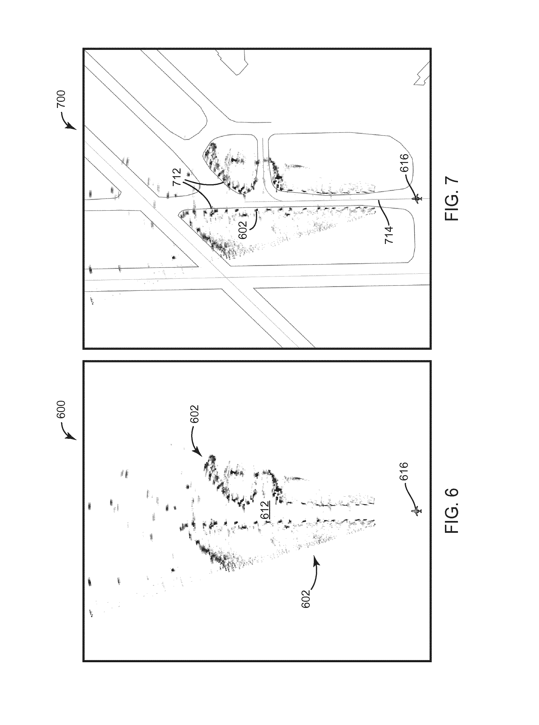
FIG. 6 is an illustration of a top down image of an airport surface environment derived from radar data provided by the display system illustrated in FIG. 2 according to yet another exemplary embodiment of the inventive concepts disclosed herein;
FIG. 7 is an illustration of a combined top down image including an image derived from surface map data and an image derived from the radar data associated with the image illustrated in FIG. 6 according to yet another exemplary embodiment of the inventive concepts disclosed herein;
FIG. 8 is an illustration of an exocentric image of an airport surface environment derived from radar data provided by the display system illustrated in FIG. 2 according to yet another exemplary embodiment of the inventive concepts disclosed herein;
FIG. 9 is an illustration of an exocentric combined image including an image derived from surface map data and an image derived from the radar data associated with the image illustrated in FIG. 8 according to yet another exemplary embodiment of the inventive concepts disclosed herein;
FIG. 10 is an illustration of a combined top down image including an image derived from surface map data and an image derived from the radar data provided by the display system illustrated in FIG. 2 according to yet another exemplary embodiment of the inventive concepts disclosed herein;
FIG. 11 is an illustration of a combined exocentric image including an image derived from surface map data and an image derived from the radar data associated with the image illustrated in FIG. 10 according to yet another exemplary embodiment of the inventive concepts disclosed herein; and
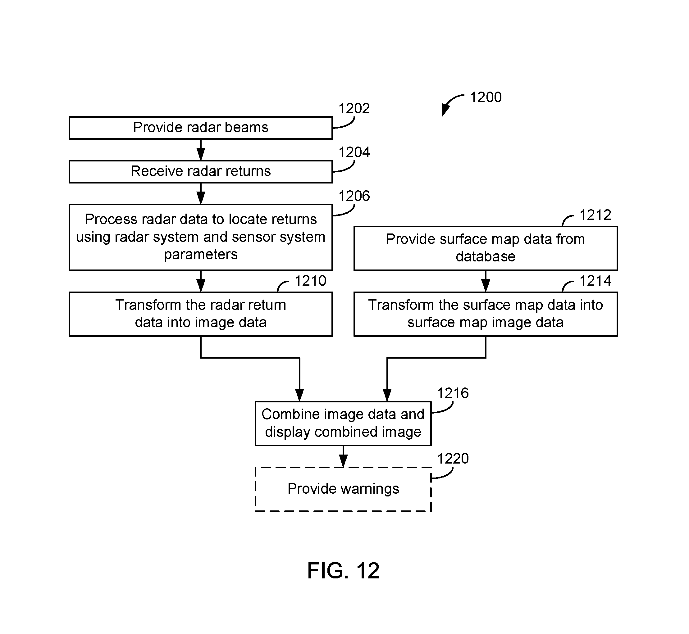
FIG. 12 is a flow diagram showing operations for the generation of image data for the display system illustrated in FIG. 2 in accordance with some embodiments of the inventive concepts disclosed herein.
DETAILED DESCRIPTION
Before describing in detail the inventive concepts disclosed herein, it should be observed that the inventive concepts disclosed herein include, but are not limited to, a novel structural combination of data/signal processing components, sensors, and/or communications circuits, and not in the particular detailed configurations thereof. Accordingly, the structure, methods, functions, control and arrangement of components, software, and circuits have, for the most part, been illustrated in the drawings by readily understandable block representations and schematic diagrams, in order not to obscure the disclosure with structural details which will be readily apparent to those skilled in the art, having the benefit of the description herein. Further, the inventive concepts disclosed herein are not limited to the particular embodiments depicted in the exemplary diagrams, but should be construed in accordance with the language in the claims.
A weather radar based surface operation display system advantageously scans a wide field of view (FOV) (e.g., more than 30 degrees in azimuth) and allows the aircraft to observe any obstacles before the taxiing aircraft commits to making a turn. The weather radar based surface operation display system does not add the additional expense associated with active sensing systems, such as, millimeter wavelength (MMW) radar systems (e.g., 94 GHz) and FLIR cameras that can have limited range in certain low visibility conditions, such as, heavy fog, rain, or other precipitation. The FLIR/camera based systems are generally limited to only seeing .about.30 degrees of view directly ahead of the aircraft and cannot see runway painted lines when the airport surfaces are obscured in snow, ice or even heavy rain. Advantageously, using a weather radar system provides greater sensing range than millimeter wavelength radar sensing systems, passive FLIR camera systems or visible light camera systems in low visibility condition in some embodiments. The weather radar system's superior ability to penetrate fog, rain, and snow allows the radar system to detect the runway edge lights during low visibility operations at a much greater distance than passive FLIR or visible light cameras in some embodiments.
In some embodiments, a weather radar is used as an imaging sensor to provide a visualization of the surrounding environment during surface operations. The visualization can be presented to the pilot on a display (e.g., head up display (HUD or head down display (HDD)), thereby allowing the pilot to see the surrounding environment in low visibility conditions. The weather radar system is configured to have sufficient resolution to detect small objects, such as, runway and taxiway edge lights in some embodiments. The weather radar is configured to perform at these higher resolutions by enhancing the angular resolution using beam sharpening with a mono-pulse or sub-aperture technique and/or by enhancing the range resolution using ultra-wideband pulsing, stepped-frequency compression, pulse compression, or other compression techniques in some embodiments.
According to various exemplary embodiments, a display system, such as an EVS, a sensor system, or a radar system, uses radar sensing to provide imagery while surface operations for a pilot or co-pilot. In some embodiments, a Doppler weather radar system is configured to have enhanced resolution (e.g., angular resolution and/or range resolution). Reflectivity of radar returns from runway structures in an airport terminal or runway environment (e.g., an edge light system) are sensed in some embodiments.
In some embodiments, a weather radar system achieves accurate location determination using an accurate beam sharpening angle. In some embodiments, the weather radar system creates a two dimensional or three dimensional grid containing the spatial density of the intensity of the radar returns. Each radar return has an associated location (e.g., location relative to the radar system) that is based on the radar antenna position in some embodiments. From the radar antenna position, the location of the radar returns is found using the attitude of the antenna, the beam sharpening angle and the range (e.g., specific to that individual radar return) in some embodiments. The radar returns are processed to determine the spatial density of the intensity associated with the radar returns. The spatial density of the intensity can be used to generate an image representing the target environment sensed by the radar scan.
Using the weather radar system configured according to some embodiments also provides EVS imagery having sufficient accuracy in low visibility conditions (given that many of the visual references required under Title 14 of the Code of Federal Regulations, part 91, such as approach lighting systems, threshold lighting systems, runway edge lighting systems, and other runway structures, are structures that exhibit high radar reflectivity). The imagery allows low visibility operations at less than 1200 feet RVR or 300 RVR and shows obstacles (e.g., other aircraft, surface vehicles, and other equipment) in the path of the aircraft in some embodiments. In some embodiments, the lack of radar returns from the runway and taxiway surface combined with returns from runway structures and lights can provide a suitable image for runway and taxiway identification by the pilot. A surface map image (e.g., from an SVS or other map system) can be combined with the radar image to provide additional information of the surface environment that can help the pilot navigate on the surface, but the provided surface map image depends on a database and on an absolute positioning and attitude sources for which integrity cannot be guaranteed. The image generated by the radar can be generated using only relative positioning and attitude sources. Combining the two independently created images confirms the alignment and colocation of the radar image and the surface map image in order to validate the integrity of the positioning and attitude sources. The combined independent images also validate the accuracy of realism of the features of the surface map database.
The radar return data is processed to provide a two-dimensional aircraft situation display (e.g., plan view display (e.g., top down)) or a three dimensional exocentric or perspective aircraft situation display representative of taxiway and runway structures in an airport terminal or runway environment based on the radar returns as described in U.S. patent application Ser. Nos. 14/841,558, 14/301,199, 14/482,681 and 14/5363,300 incorporated herein by reference in their entireties in some embodiments. For example, the radar processing circuit can be embodied as a processor and a non-transitory memory containing program instructions that, when executed, cause the processor to instruct the radar system to provide radar beams and receive radar returns via the antenna and generate image data from the radar returns.
According to some embodiments, a radar system, such as, a weather radar system, can be used to sense features of a runway environment. In some embodiments, the regular, periodic, equal spacing nature of visual aids, such as, approach lighting system, runway edge lights, taxi way lights, and/or center line lights, are identified from the image generated from the radar data. In certain embodiments, the systems and methods can be utilized as an extension to a combined vision system (CVS).
Referring to FIG. 1, a vision or display system 10 is provided in an aircraft having an aircraft control center 11 or cockpit. The display system 10 can be used in surface operations, such as, taxi operations, to view the environment during ground operations. The aircraft control center 11 includes displays 20 embodied as head down displays (HDDs) or flight displays. The aircraft control center 11 can also include one or more combiners, such as a combiner 21 associated with a head up display (HUD) system. In some embodiments, the combiner 21 is provided as part of a wearable HUD. Conformal images are provided on the combiner 21 in some embodiments.
The displays 20 and the combiner 21 can be used to provide information to the flight crew, thereby increasing visual range and enhancing decision-making abilities. In some embodiments, the displays 20 and the combiner 21 include a weather display, a joint display, a weather radar surface map and a terrain display. Further, the displays 20 may include images from a synthetic vision system (SVS) or an enhanced vision system (EVS) (e.g., an EFVS). For example, the displays 20 include a display 22 configured to display a perspective image 24, exocentric image, or surface map image of the surface environment of the aircraft. Combiner 21 also or alternatively displays a perspective image 25, an exocentric image or a surface map image of the surface environment of the aircraft in some embodiments Other views of terrain and/or weather information may also be provided (e.g., plan view, horizontal view, vertical view, or combinations thereof). The displays 20 can be implemented using any of a variety of display technologies, including CRT, LCD, organic LED, dot matrix display, and others.
According to some embodiments, the display system 10 is configured to provide an image in response to radar data to at least one of the displays 20 or the combiner 21. In FIG. 1, the perspective image 25 on the combiner 21 includes surface features 29 associated with a runway 30 as viewed from the aircraft (e.g., during surface operations). In some embodiments, at least one of the displays 20 or the combiner 21 displays a combined image of the environment associated with the runway 30 derived from two or more of enhanced vision data, radar data, and surface map data (e.g., SVS data). Advantageously, real time radar data can be provided to provide a real time, all weather detection of the surface features 29 associated with the runway 30 in one embodiment. Advantageously, the radar data allows the runway 30 as well as taxiways and their orientation to be viewed by one or more pilots during low visibility operations in some embodiments.
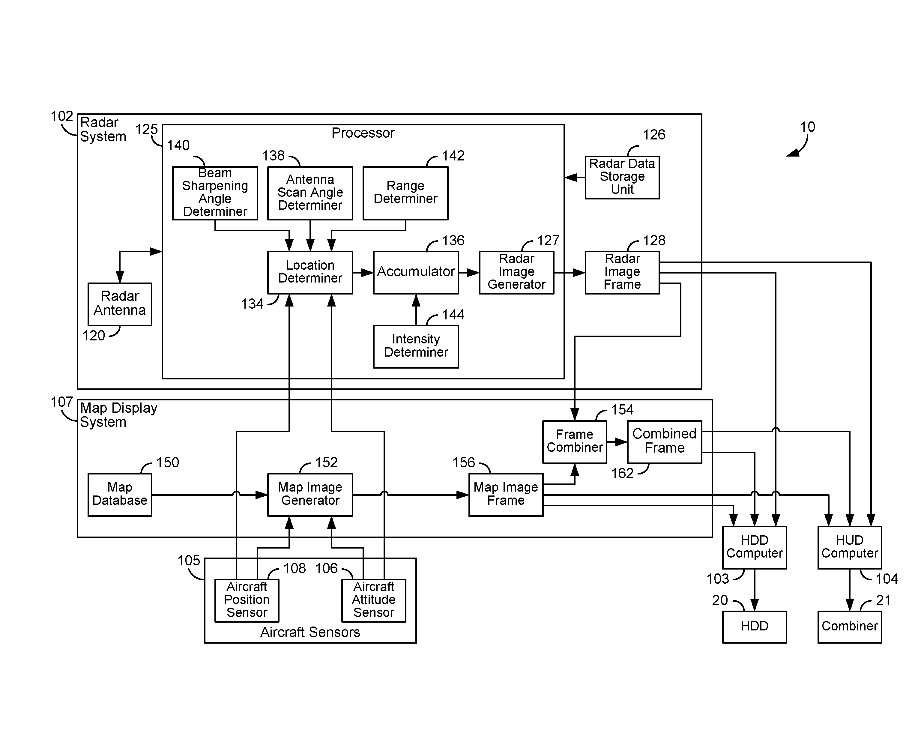
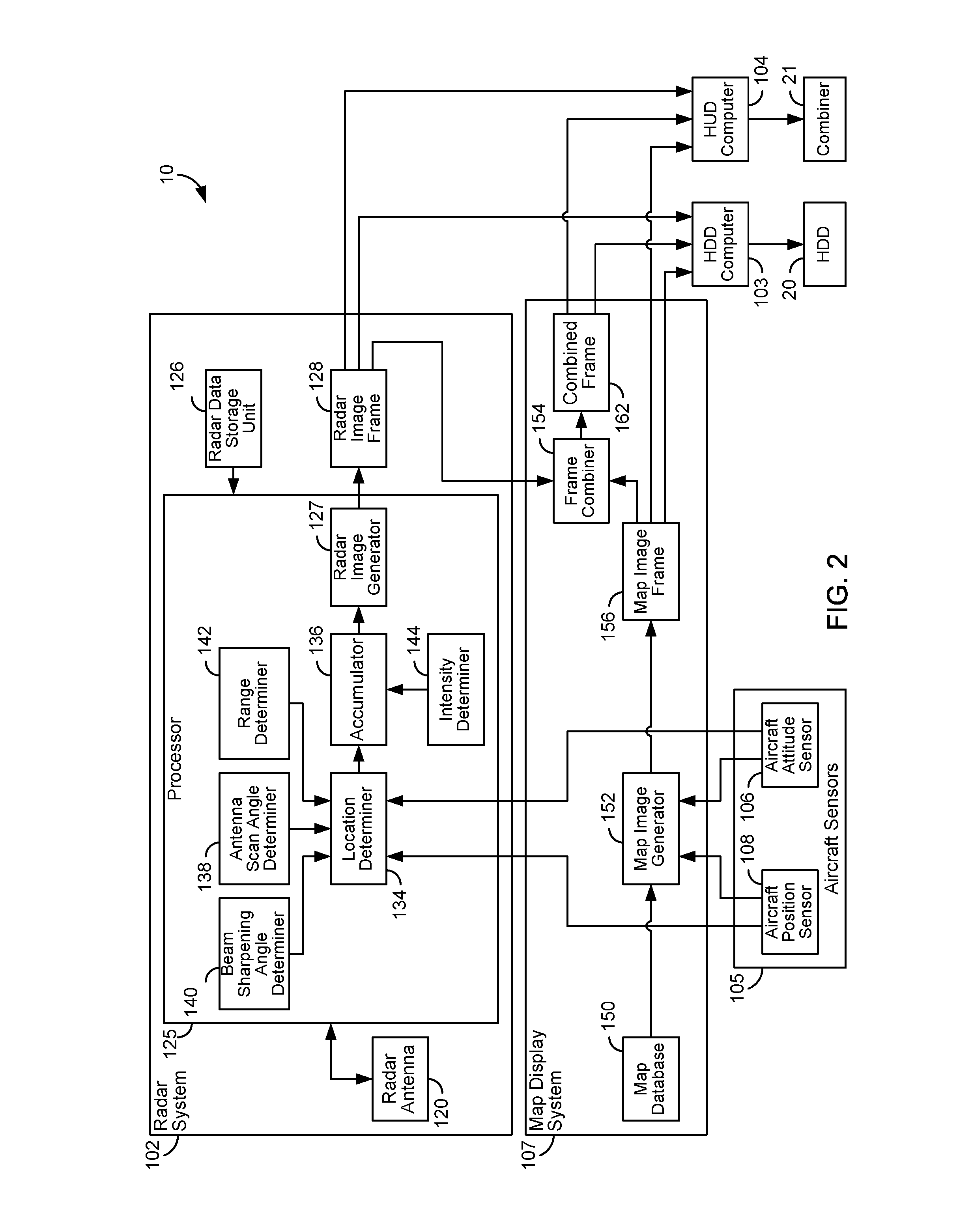
Referring to FIG. 2, the display system 10 uses radar data from a radar system 102 to provide an image to any of the displays 20 via a HDD computer 103 or the combiner 21 via a HUD computer 104 in some embodiments. The display system 10 is in communication with or includes the radar system 102 and aircraft sensors 105 and can include or be in communication with a map display system 107 (e.g., an SVS and/or an EVS) in some embodiments. The map display system 107 is optional in some embodiments.
The aircraft sensors 105 are associated with navigation equipment and flight control devices in some embodiments and can include one or more of an inertial navigation system (INS), an inertial reference system (IRS), a flight computer, a barometric altimeter, a radar altimeter, a global navigation satellite system (GNSS), air speed sensors, heading sensors, etc. The aircraft sensors 105 include an aircraft attitude sensor 106 and an aircraft position sensor 108 in some embodiments.
The aircraft position sensor 108 is any device or system for providing an electronic signal or data representing aircraft position. In some embodiments, the aircraft position includes a position parameter (e.g., latitude and longitude) and an aircraft altitude parameter. The aircraft position sensor 108 is a GNSS or INS in some embodiments. The aircraft altitude can be provided by a GNSS, an altitude sensor (e.g., barometric sensor), an INS, or other device. In some embodiments, the aircraft position also includes velocity and acceleration parameters associated with aircraft position (e.g., for predicting future position of the aircraft).
The aircraft attitude sensor 106 is any device for providing an electronic signal or data representing attitude of the aircraft. The aircraft attitude includes a heading parameter, a pitch parameter, a yaw parameter, and a roll parameter in some embodiments. In some embodiments, the aircraft position sensor 108 and the aircraft attitude sensor 106 are parts of a single positioning or navigation sensor system, such as a GNSS or INS or an integrated GNSS/INS. In some embodiments, the aircraft attitude also includes angular velocity and acceleration parameters associated with attitude (e.g., for predicting future attitude of the aircraft). In some embodiments, the radar antenna 120 has an attitude sensor for providing attitude and changes in attitude of the radar antenna 120 with respect to the aircraft. The attitude of the radar antenna 120 relative to the attitude of the aircraft can be represented by a scan angle parameter for the radar antenna 120.
The radar system 102 receives data from the aircraft sensors 105 and provides radar image data for display by display system 10. The radar system 102 is a weather radar system generally located inside the nose of the aircraft, inside a cockpit of the aircraft, on the top of the aircraft or on the tail of the aircraft in some embodiments. The radar system 102 includes a radar antenna 120, a processor 125, a radar data storage unit 126, and an image frame memory 128. The radar system 102 can be a weather radar system, such as, a Multiscan.TM. radar system from Rockwell Collins, Inc. configured as described herein. The radar system 102 utilizes a split, half or sub-aperture or other technique for obtaining radar data associated with external surroundings in some embodiments. The radar system 102 can use the split or sub-aperture techniques of the radar systems described in U.S. application Ser. Nos. 14/841,558, 13/627,788, now U.S. Pat. No. 9,024,805, Ser. No. 12/892,563, now U.S. Pat. No. 8,643,533, Ser. No. 13/250,798, now U.S. Pat. No. 9,562,788, Ser. No. 12/236,464, now U.S. Pat. No. 8,977,491, Ser. No. 12/167,200, now U.S. Pat. No. 7,889,117 and U.S. Pat. No. 8,077,078, incorporated herein by reference in their entirety and assigned to the assignee of the present application. The type of the radar system 102 and data gathering techniques are not discussed in the specification in a limiting fashion.
The processor 125 uses radar data stored in the radar data storage unit 126 and the data from the aircraft sensors 105 to provide and store radar image data in the image frame memory 128. The radar data can be provided directly from the transmit/receive circuits associated with the radar antenna 120 or be stored in the processor 125 in some embodiments. The processor 125 includes a location determiner 134, an accumulator 136, an antenna scan angle determiner 138, a beam sharpening angle determiner 140, a range determiner 142, an intensity determiner 144, and a radar image generator 127. In some embodiments, the radar image generator 127 is separate from the processor 125 and is part of a graphics processor or other display processor. The accumulator 136, the location determiner 134, the radar data storage unit 126, the antenna scan angle determiner 138, the beam sharpening angle determiner 140, the range determiner 142, the intensity determiner 144, and the radar image generator 127 are software modules, circuits, or combinations thereof in some embodiments.
The location determiner 134 uses data from the aircraft sensors 105 and from the radar data storage unit 126, the antenna scan angle determiner 138, the beam sharpening angle determiner 140, and the range determiner 142 to identify a location associated with radar returns received at the radar antenna 120 in some embodiments. The locations are relative to the aircraft or the radar system 102 (e.g., the radar antenna 120 or pilot's position) and are determined without the use of an absolute position source (e.g., a GNSS) in some embodiments. The data associated with the radar returns are stored in the radar data storage unit 126 in some embodiments. The location determiner 134 uses the position of the radar antenna 120, the attitude of the aircraft, the antenna pointing angle, the beam sharpening angle, and the range to determine the location associated with the radar returns in some embodiments. The intensity determiner 144 determines an intensity associated with the radar returns in some embodiments. The intensity of a collection of radar returns are accumulated by location in the accumulator 136 in some embodiments.
The processor 125 causes the radar antenna 120 to provide radar signals or beams and to receive radar returns (e.g., weather radar returns data). The processor 125 is an electronic processor that processes the radar returns and provides the radar data associated with the radar returns to the radar data storage unit 126. The radar signals and radar returns are in the X-band or C-band in some embodiments.
The radar system 102 provides the radar data (e.g., weather radar return data) to the radar data storage unit 126 in one embodiment. The radar data can be processed and filtered for various weather sensing functions as well as location determination functions. In some embodiments, the radar image generator 127 provides the radar image data (e.g., in image frame format) for storage in the image frame memory 128 using the accumulated radar returns in the accumulator 136. In some embodiments, the accumulator 136 determines the spatial density of the intensity by area or volume to create the radar image data. The spatial density of the intensity is used by the radar image generator 127 to provide the radar image data indicative of intensity of radar returns at locations associated with that area or volume.
The image frame memory 128 is a video or graphic electronic memory in some embodiments. The radar image data represents an exocentric, perspective and/or surface map view image in some embodiments. The radar image generator 127 and the accumulator 136 are an electronic memory, processor circuitry, or combination thereof in some embodiments. In some embodiments, the radar image generator 127 and accumulator 136 are part of a digital signal processor or the processor 125 or is a software module executing on the digital signal processor or the processor 125. The radar image generator 127 and accumulator 136 are embodied as a register in some embodiments. The radar data storage unit 126 is an electronic memory in some embodiments.
In some embodiments, a location translation operation is performed by the radar image generator 127 to project the radar return data into radar image data. In some embodiments, the radar image generator 127 is using a projection viewpoint reference for generating the radar image data that is using the same location and attitude reference as the projection viewpoint that the map image generator 152 is using for generating the surface map image data to generate a perspective view, or an exocentric view, or a plan view.
The radar data associated with the external surroundings can represent sensed targets and the location of the sensed targets. Targets include terrain, man-made features, objects, runways, etc. Improved angular resolution and range resolution techniques discussed in U.S. patent application Ser. No. 14/536,330 filed Nov. 7, 2014 by Jinkins et al. incorporated herein by reference in its entirety allows the location of the targets to be more accurately determined and represented in the radar image data in some embodiments. The radar system 102 can utilize clutter suppression and Doppler filtering to improve performance in some embodiments.
In some embodiments, the radar system 102 provides radar data representing a 120 degree field of view in accordance with a weather radar sweep. The sweep can be limited to a 30 degree sweep in certain embodiments. The sweep is directed toward the surface of the Earth so that returns are obtained which allow runway environment features to be sensed. Various types of sweeps, sweep patterns, and sweep speeds can be utilized without departing from the scope of the inventive concepts disclosed herein.
The radar system 102 embodied as a weather radar allows existing avionic equipment to be used as a real-time sensor for providing a radar-derived enhanced image of the external scene topography to the pilot in some embodiments. The image or representation generated by the radar system 102 is provided on the displays 20 or the combiner 21 can function as an EVS to provide situation awareness to the pilot in some embodiments. In some embodiments, the image or representation generated by the radar system 102 is provided on the displays 20 or the combiner 21 can be part of a low visibility operations system approved for use at lower RVR.
The radar system 102 advantageously provides increased range resolution in some embodiments. The increased resolution in range and angle allows a higher resolution for the location determination by the location determiner 134 and hence higher image resolution to be provided on the displays 20 and the combiner 21 in some embodiments.
According to some embodiments, the radar system 102 uses a beam sharpening method to achieve increased angular resolution. In some embodiments, the radar system 102 uses techniques, such as, beam sharpening (e.g., horizontal beam sharpening) and de-convolution of the beam point spread function for improved angular resolution. In some embodiments, the radar system 102 can use beam sharpening as a process that improves the antenna-induced poor angular resolution (e.g., due to the beam width). There are many methods that can be used such as: Monopulse Radar, Sub-Aperture Radar or Split-Aperture Radar, etc. Mathematical methods can be utilized to determine a center of the radar echo for identifying runway features. Techniques for beam sharpening and determining beam sharpening angles and scan angles are discussed in U.S. patent application Ser. No. 13/627,788, filed Sep. 26, 2012, now U.S. Pat. No. 9,024,805; Ser. No. 12/892,563, filed Sep. 28, 2010, now U.S. Pat. No. 8,643,533; Ser. No. 13/250,798, filed Sep. 30, 2011, now U.S. Pat. No. 9,562,788; Ser. No. 12/236,464, filed Sep. 23, 2008, now U.S. Pat. No. 8,977,491; and Ser. No. 12/167,200 filed Jul. 2, 2008, now U.S. Pat. No. 7,889,117; and U.S. Pat. No. 8,077,078 incorporated herein by reference in their entireties.
The radar system 102 uses the radar antenna 120 that toggles between transmitting and receiving on the full aperture and transmitting on the full aperture while receiving on the partial aperture in some embodiments. These techniques can be used to accurately estimate at which angle the measurement was located within the radar beam in some embodiments. The received returns are processed to determine a high resolution estimate of a measurement angle relative to the boresight of the antenna beam in some embodiments. According to some embodiments, the returns are processed using a complex conjugate multiplication method to determine the beam sharpening angle determined by the beam sharpening angle determiner 140. The processing can be related to sequential lobing processing but is executed in the phase domain as opposed to the common amplitude domain in some embodiments.
In some embodiments, the radar system 102 uses sequential lobing techniques where two antennas that are close to the same place may be used, going back and forth between the two antennas. An amplitude signature or phase signature that varies between the two halves of the antennas may be used to obtain data about the location associated with the returned radar reflection from a sensed target (e.g., an object such as other aircraft, terrain, lights, or towers). Sequential lobing generally does not use phase comparisons with moving targets due to Doppler-induced phase changes that contaminate the phase center measurement. However, using a complex conjugate multiply method allows the Doppler-induced phase changes to be removed by cancellation. Therefore, a change in phase center between multiple different sub-apertures may be determined and used to determine the beam sharpening angle associated with the returned radar reflection from a sensed target.
In some embodiments, the effective waveform bandwidth of the radar system 102 is increased to increase range resolution. To provide higher range resolution, the radar system 102 provides ultra-wideband radar (UWB) pulses (e.g., extremely narrow pulses with high power), or provides intra pulse compression (frequency of phase modulation of the transmitted pulse) in some embodiments. Frequency coding techniques including the common linear frequency modulation (LFM) or chirp method and discrete coded segments within the pulse are utilized in some embodiments. Phase coding techniques including binary phase codes as well as various polyphase codes can be utilized in some embodiments. To provide higher range resolution, the radar system 102 provides interpulse pulse compression or stepped frequency compression (e.g., successive pulses with discrete increasing frequency steps) in some embodiments. In some embodiments, stepped frequency compression advantageously achieves high effective bandwidth with narrow instantaneous bandwidth. The receive bandwidth is smaller, has lower noise bandwidth, and a higher signal to noise ratio in some embodiments. Analog-to-digital sampling rates are lower (vs. pulse-compression) in some embodiments. In addition, the stepped frequency compression also has a smaller peak power (e.g., when compared to impulse), provides flexible transmit frequency control, can "hop" over restricted or undesired transmit frequencies, enables adaptive/cognitive frequency use, and rejects later received clutter from earlier transmit pulses in some embodiments. Further, the stepped frequency compression techniques can provide returns from clutter in ambiguous ranges that have frequencies that are different from returns from targets and rejects ambiguous clutter returns in the receiver IF filter of the radar system 102 in some embodiments. Stepped frequency compression generally does not achieve range resolution with a single pulse, requires transmit, receive and processing of a group of pulses for any one bin, and has more pronounced range-Doppler coupling (e.g., different Doppler shifts for each frequency) in some embodiments.
The processor 125 can be any hardware and/or software processor or processing architecture capable of executing instructions and operating on navigational and radar data. The processor 125 can be capable of determining navigational information such as altitude, heading, bearing, location, and changes thereof based on data from the aircraft sensors 105. The processor 125 can be, or can include one or more microprocessors, an application specific integrated circuit (ASIC), a circuit containing one or more processing components, a group of distributed processing components, circuitry for supporting a microprocessor, or other hardware configured for processing.
In some embodiments, the display system 10 includes the map display system 107 including a surface map database 150, a surface map image generator 152, a frame combiner 154, a surface map image frame memory 156, and a combined image frame memory 162. Surface map image frame memory 156 and the combined image frame memory 162 are similar to the image frame memory 128. In some embodiments, the display system 10 is configured to provide a combined image using the radar image data stored in the image frame memory 128 and a surface map image stored in the surface map image frame memory 156.
The surface map image generator 152 is configured to provide an image based upon aircraft position as sensed by aircraft sensors 105 and surface feature data stored in the surface map database 150. The surface map image is generated as an exocentric, perspective, top down and/or plan view in some embodiments.
In some embodiments, the surface map database 150 is memory unit storing surface feature data including airport surface data referenced to absolute coordinate locations. In some embodiments, the surface map image generator 152 and the frame combiner 154 are software modules (e.g., executed on processor 125), circuits, or combinations thereof in some embodiments. A hardware platform associated with the radar system 102 (e.g., the processor 125), an SVS, or an EVS can be used to provide the operations of the map display system 107.
The surface map image generator 152 provides surface map image data in response to absolute position and attitude sensed using aircraft sensors 105. The surface map image data can be referenced to absolute locations. SVS and surface mapping routines can be used to provide the surface map image data in response to position, attitude, and movement. In some embodiments, the map image generator 152 is using a projection viewpoint reference for generating the surface map image data that is using the same location and attitude reference as the projection viewpoint that the radar image generator 127 is using for generating the radar image data to generate a perspective view, or an exocentric view, or a plan view. The surface map image data is stored in surface map image frame memory 156 and can be displayed on the combiner 21 or the displays 20 via HUD computer 104 and HDD computer 103, respectively.
In some embodiments, the frame combiner 154 receives the surface map image data from the surface map image frame memory 156 or surface map image generator 152, receives the radar image data from the image frame memory 128 or the radar image generator 127, and provides combined image data to the combined image frame memory 162. The combined image data can be displayed on the combiner 21 or the displays 20 via HUD computer 104 and HDD computer 103, respectively. In some embodiments, both the surface map image data and the radar image data are generated from the same viewpoint using the same projection method so that both images are in the same location, format and size and are overlaid upon each other to provide the combined image data. In some embodiments, the radar image data is generated only using relative positioning and attitude sources and the surface map image data is generated using absolute positioning and attitude sources. In some embodiments, the radar image data has priority over the surface map image data so that sensed images associated with the radar image data are displayed and not blocked or overwritten by features in the surface map image data. Other merging techniques can be utilized by the frame combiner 154.
With reference to FIG. 3, a flow 300 can be performed by the display system 10 in some embodiments. Flow 300 can be similar to flow 300 discussed in U.S. patent application Ser. No. 14/841,558 filed Aug. 31, 2015, now U.S. Pat. No. 9,024,805. The processor 125, map display system 107, or other computing platform can execute flow 300 to provide an image while the aircraft is involved in surface operations in response to aircraft sensor parameters and radar data. The aircraft sensor parameters from aircraft sensors 105 and the radar returns received by the radar antenna 120 are processed to determine locations and intensity associated with the returned radar reflection to provide locations which have an intensity of the radar return. These radar returns with their associated location and intensity are accumulated over an area or volume at an operation 304. The locations are determined as relative locations from the aircraft, radar system 102 or radar antenna 120 in some embodiments.
A collection of radar returns with associated return intensity parameters 302 are processed on a location basis in the operation 304 using the relative location of the radar returns parameters 303. In some embodiments, the operation 304 accumulates the return intensity parameters 302 by location to provide the spatial density of the intensity parameters 305. In some embodiments, the accumulation step is not performed. The accumulated relative positioned radar returns or spatial density of the intensity parameters 305 are transformed to the desired viewpoint to provide radar image data 308 in an operation 306 using geometric projection in some embodiments. The flow 300 is used to create an image from the accumulated relative positioned radar return data or spatial density of the intensity parameters 305 (e.g., the spatial density of the intensity from the collection of radar returns that each have an associated location and intensity (e.g., the return intensity parameters 302, and relative location of radar returns parameters 302)) in some embodiments. The radar image data 308 is used in enhanced radar image data or combined image data 370 in some embodiments.
In an operation 310, the radar system 102 uses changes in aircraft position and attitude parameters from the aircraft sensors 105 to provide the relative location of radar returns parameters 303 used in the operation 304. The operation 310 uses a relative change in position parameter 311 associated with the radar antenna 120, a range of the radar returns parameter 312, and a relative direction of the radar returns parameter 314 to determine the relative location of radar returns parameters 303. In some embodiments, the radar returns have a relative location with respect to a position at the beginning of a certain timeframe. In some embodiments the start of that timeframe is the start of the data collection that is used to generate the radar data required to generate a single radar image. In some other embodiments the start of that timeframe is the start of a radar scan. The relative locations generated by operation 310 are relative to a position at the beginning of a timeframe and operation 310 accommodates changes in position determined from the relative change in position parameter 311. The operation 310 is a geometry process for the radar returns that places each return in its appropriate location.
The relative direction of the radar returns parameter 314 is determined from an operation 322 which combines an antenna scan angle parameter 316 of the radar antenna 120, a beam sharpening angle parameter 318, and a relative change in attitude (e.g., heading) parameter 320. Aircraft and radar antenna attitude and angular velocity parameters from the aircraft sensors 105 (e.g., pitch, roll, heading, pitch rate, roll rate, yaw rate and scan angle) are used in operation 322 in some embodiments.
The radar system 102 uses an aircraft attitude parameter from the aircraft sensors 105 to perform the operation 322 with the antenna scan angle parameter 316, the beam sharpening angle parameter 318 and the relative change in attitude parameter 320. The operation 322 is a combination operation that provides the relative direction of radar returns parameter 314 in some embodiments.
The heading from the aircraft attitude sensor 106 is the direction of the longitudinal axis of the aircraft with respect to North in some embodiments. The antenna scan angle parameter 316 represents the direction of the boresight of the radar antenna 120 with respect to the heading of the aircraft in some embodiments. The beam sharpening angle parameter 318 represents the radar sensed direction of the radar returns with respect to the boresight of the radar antenna 120 in some embodiments. In some embodiments, heading is not used directly, but instead only changes in the heading are used to determine the relative direction of the radar returns parameter 314. In some other embodiments, the angular velocity parameter that is the derivative of the heading, the heading rate, is used to determine the changes in the heading instead of using the heading. In some embodiments, the relative change in heading is determined relative to the heading at the beginning of a certain timeframe. In some embodiments the start of that timeframe is the start of the data collection that is used to generate the radar data required to generate a single radar image. In some other embodiments the start of that timeframe is the start of a radar scan.
The operation 304 accumulates the radar return intensity parameters 302 based on the relative location of those radar returns 303. The intensity can be sensed as a decibel (dB) value of electromagnetic energy received at the radar antenna 120. All radar returns have a location and intensity value in some embodiments. In some embodiments the intensity is a measure for the power of the reflected radio energy.
The operation 306 provides the radar image data 308 using a relative viewpoint position and attitude with respect to the radar or viewpoint parameters 326 associated with radar antenna 120 and a projection method parameter 328. In some embodiments the image generation operation of 306 using the viewpoint parameters 326 and projection method parameters 328 generates perspective image data, exocentric image data, or surface map image data.
Flow 300 includes an optional flow 350 in some embodiments. Flow 350 is used to provide surface map image data 362 that is provided in the combined image data 370. The operation 358 uses geometry projection to provide the surface map image data 362 using projection parameters 360, an absolute position of a viewpoint 352, an absolute attitude of a viewpoint 354, and surface map data 356. The surface map image data 362 is generated using the same position and attitude of the viewpoint as used for generation of the radar image data 308 in operation 306, but for operation 358 the absolute position values of the viewpoint 352 and absolute attitude values of the viewpoint 354 are used instead of relative position and attitude values of the viewpoint. In some embodiments the image generation operation of 358 using viewpoint parameters 352 and 354 and projection parameters 360 generates perspective image data, exocentric image data, or surface map image data. The surface map image data 362 is combined with the radar image data to provide the combined image data 370 from the same viewpoint with the same projection method in some embodiments. Various image generation routines also used for synthetic vision and surface mapping can be utilized in the operation 358.
In some embodiments, a pilot can ascertain if there is a mismatch error by observing the combined image associated with the combined image data 370. In some embodiments, a pilot can ascertain if there is an obstacle in the path of the aircraft by observing the combined image associated with the combined image data 370 or the radar image associated with the radar image data 308.
With reference to FIG. 4, an image 400 of the external scene derived from the radar data associated with the radar returns includes features 402 associated with taxiway or runway edge lights of a runway 412. An absence of return energy is associated with the taxiway or runway 412 in some embodiments. Image 400 is a perspective view from the pilot's eye and is suitable for display on the combiner 21 as a conformal image with the real world view in some embodiments. Image 400 is provided using the radar data referenced locally to the aircraft and without absolute data from a GNSS or other absolute positioning system in some embodiments.
With reference to FIG. 5, an image 500 includes the image 400 derived from the radar data associated with the radar returns and a surface map image derived from surface map image data. The surface map image includes surface features 512 associated with a taxiway or runway edge and a feature 514 associated with a taxiway or runway centerline which are derived from data in the map database 150. Image 500 is a perspective view from the pilot's eye and is suitable for display on the combiner 21 as a conformal image with the real world view in some embodiments.
With reference to FIG. 6, an image 600 of the external scene derived from the radar data associated with the radar returns includes features 602 associated with taxiway or runway edge lights of a taxiway 612 or runway. An absence of return energy is associated with the taxiway 612 in some embodiments. Image 600 is a top down view. Image 600 is provided using the radar data referenced locally to an aircraft 616 including the radar system 102 and without absolute data from a GNSS or other absolute positioning system in some embodiments.
With reference to FIG. 7, an image 700 includes the image 600 derived from the radar image data associated with the radar returns and a surface map image derived from surface map image data. The surface map image data provides image features 712 associated with the edge of the taxiway 612 or runway and a feature 714 associated with a taxiway or runway centerline which are derived from data in the map database 150. Image 700 is generated as a top down view.
With reference to FIG. 8, an image 800 of the external scene derived from the radar data associated with the radar returns includes features 802 associated with taxiway or runway edge lights of a taxiway 812 or runway. An absence of return energy is associated with the taxiway 812 or runway in some embodiments. Image 800 is generated as an exocentric view. Image 800 is provided using the radar data referenced locally to an aircraft 816 including the radar system 102 and without absolute data from a GNSS or other absolute positioning system in some embodiments.
With reference to FIG. 9, an image 900 includes the image 800 derived from the radar data associated with the radar returns and a surface map image derived from surface map image data. The surface map image data provides image features 912 associated with a taxiway or runway edge and a feature 911 associated with a taxiway or runway centerline. Image 900 is generated as an exocentric view.
With reference to FIG. 10, an image 1000 is a top down view image derived from the radar data associated with the radar returns and a surface map image derived from surface map image data. The image derived from the radar data associated with the radar returns includes features 1002 associated with edge lights of a taxiway 1012 or runway. The surface map image data provides image features 1016 associated with a taxiway or runway edge and a feature 1017 associated with a taxiway or runway centerline. The image 1000 shows an obstacle 1020 in the path of aircraft 1022. Obstacle 1020 is an aircraft sensed by radar system 102 associated with aircraft 1022 during low visibility operations.
With reference to FIG. 11, an image 1100 is an exocentric view image derived from the radar data associated with the radar returns and a surface map image derived from surface map image data. The image derived from the radar data associated with the radar returns includes features 1102 associated with taxiway or runway edge lights of a taxiway 1112 or runway. The surface map image data provides image features 1116 associated with a taxiway or runway edge. The image 1100 shows an obstacle 1120 in the path of aircraft 1122. The obstacle 1120 is an aircraft sensed by the radar system 102 associated with aircraft 1122 during low visibility operations.
With reference to FIG. 12, a flow 1200 can be performed by the display system 10 in some embodiments. The processor 125 or other computing platform can execute flow 1200 to provide an image in response to aircraft sensor parameters and radar data. At an operation 1202 radar beams are provided by the radar antenna 120. At an operation 1204, radar returns are received by the radar antenna 120. At an operation 1206, the radar data and aircraft sensor data associated with the radar returns are processed to provide the location of the radar returns. In some embodiments, the radar system 102 provides data representing a 120 degree field of view in accordance with a weather radar sweep in one embodiment. The width of the sweep can be limited during surface operations to provide the radar data for a 30-40 degree wide display in certain embodiments. In some embodiments the sweep can be horizontally directed in the direction of the turn to provide radar data of the area where the aircraft is steering towards. The sweep is directed toward the surface of the Earth so that returns are obtained which allow a surface image to be created. Various types of sweeps, scans and timings of sweeps and scans can be utilized without departing from the scope of the invention.
The radar data is processed to determine the intensity and location of the radar returns. The locations of the radar returns are determined using the radar data and parameters from the aircraft sensors 105 (e.g., according to flow 300) in some embodiments. At an operation 1210, radar image data is generated from the radar returns with their associated intensity and location data. The radar image data is generated based on a transformation using a viewpoint and projection method. The location of the viewpoint is relative to the radar system 102 in some embodiments. At an operation 1212, surface map data is provided from a surface map database. At an operation 1214, surface map image data is generated from the surface map data. The surface map image data is generated based on a transformation using a viewpoint and projection method. The location of the viewpoint is related to the absolute coordinates of the surface map database in some embodiments. In some embodiments the viewpoint location and projection method for operation 1210 and operation 1214 are the same, even though the viewpoint location can be referenced relative or absolute for operations 1210 and 1214. At an operation 1216, the radar image data from operation 1210 and surface map image data from operation 1214 is combined to provide combined image data for display.
In some embodiments the combined image data can be from the perspective of the pilot's eye in the aircraft flight deck. In some other embodiments the combined image data can be from the perspective of a viewpoint behind the aircraft directed towards the aircraft also known as an exocentric perspective. In yet other embodiments the combined image data can be from the perspective of a viewpoint above the aircraft directed down towards the aircraft also known as a top down perspective. The locations of the viewpoints are derived from aircraft attitude, velocity and positioning sources, such as the aircraft sensors 105. Operation 1216 combines the images in such a way that the identity of the two image sources is still maintained in some embodiments. The display system 10 combines or fuses the independently created images from both the surface map database (e.g., SVS database) and the images derived from radar data from the radar system 102 to confirm the integrity of the positioning and attitude source along with the accuracy of the surface map database according to some embodiments.
In some embodiments, the surface map image data and the radar image data are compared and warnings are provided if there is a mismatch in an operation 1220. For example, if edge lights detected in the radar image data are not within a tolerance for locations for such lights in the surface map data, a data mismatch error is provided. In some embodiments, the pilot or flight crew can observe a mismatch error based upon edge lights being out of alignment with the edge of the runway in the surface map image.
Various matching algorithms can be utilized to determine if the radar image data and the surface map image data are mismatched. The compare function generally looks for specific airport features and performs such comparisons on a regular, repeated, periodic schedule (e.g., every couple of seconds). In some embodiments, surface features, such as runway features, can be matched. Runway features are readily ascertainable from radar data. If the compare function indicates that there is not a match, a monitor indicates there may be a database error or an error with the radar system 102 or a positioning or attitude error associated with the aircraft sensors 105. The indication can be provided on the combiner 21 or on the displays 20.
The scope of this disclosure should be determined by the claims, their legal equivalents and the fact that it fully encompasses other embodiments which may become apparent to those skilled in the art. All structural, electrical and functional equivalents to the elements of the above-described disclosure that are known to those of ordinary skill in the art are expressly incorporated herein by reference and are intended to be encompassed by the present claims. A reference to an element in the singular is not intended to mean one and only one, unless explicitly so stated, but rather it should be construed to mean at least one. No claim element herein is to be construed under the provisions of 35 U.S.C. .sctn. 112, sixth paragraph, unless the element is expressly recited using the phrase "means for." Furthermore, no element, component or method step in the present disclosure is intended to be dedicated to the public, regardless of whether the element, component or method step is explicitly recited in the claims.
Embodiments of the inventive concepts disclosed herein have been described with reference to drawings. The drawings illustrate certain details of specific embodiments that implement the systems and methods and programs of the present disclosure. However, describing the embodiments with drawings should not be construed as imposing any limitations that may be present in the drawings. The present disclosure contemplates methods, systems and program products on any machine-readable media for accomplishing its operations. Embodiments of the inventive concepts disclosed herein may be implemented using an existing computer processor, or by a special purpose computer processor incorporated for this or another purpose or by a hardwired system.
Embodiments in the inventive concepts disclosed herein have been described in the general context of method steps which may be implemented in one embodiment by a program product including machine-executable instructions, such as program code, for example in the form of program modules executed by machines in networked environments. Generally, program modules include routines, programs, objects, components, data structures, etc. that perform particular tasks or implement particular abstract data types. Machine-executable instructions, associated data structures, and program modules represent examples of program code for executing steps of the methods disclosed herein. The particular sequence of such executable instructions or associated data structures represent examples of corresponding acts for implementing the functions described in such steps.
It should be noted that although the diagrams herein may show a specific order and composition of method steps, it is understood that the order of these steps may differ from what is depicted. For example, two or more steps may be performed concurrently or with partial concurrence. Also, some method steps that are performed as discrete steps may be combined, steps being performed as a combined step may be separated into discrete steps, the sequence of certain processes may be reversed or otherwise varied, and the nature or number of discrete processes may be altered or varied. The order or sequence of any element or apparatus may be varied or substituted according to alternative embodiments. Accordingly, all such modifications are intended to be included within the scope of the present disclosure.
The foregoing description of embodiments has been presented for purposes of illustration and description. It is not intended to be exhaustive or to limit the subject matter to the precise form disclosed, and modifications and variations are possible in light of the above teachings or may be acquired from practice of the subject matter disclosed herein. The embodiments were chosen and described in order to explain the principals of the disclosed subject matter and its practical application to enable one skilled in the art to utilize the disclosed subject matter in various embodiments and with various modifications as are suited to the particular use contemplated. Other substitutions, modifications, changes and omissions may be made in the design, operating conditions and arrangement of the embodiments without departing from the scope of the presently disclosed subject matter.
* * * * *
References
-
pcavionics.com
-
uasc.com
-
aviationtoday.com
-
aai.aero/aai_employees/chapter_7.pdf
-
bluemountainavionics.com
-
proceedings.spiedigitallibrary.org
-
buy.garmin.com/shop/shop.do?cID=153&pID=97668
-
-
-
tunnel-in-the-sky.tudelft.nl
-
delftoutlook.tudelft.nl
D00000
D00001
D00002
D00003
D00004
D00005
D00006
D00007
D00008
XML
uspto.report is an independent third-party trademark research tool that is not affiliated, endorsed, or sponsored by the United States Patent and Trademark Office (USPTO) or any other governmental organization. The information provided by uspto.report is based on publicly available data at the time of writing and is intended for informational purposes only.
While we strive to provide accurate and up-to-date information, we do not guarantee the accuracy, completeness, reliability, or suitability of the information displayed on this site. The use of this site is at your own risk. Any reliance you place on such information is therefore strictly at your own risk.
All official trademark data, including owner information, should be verified by visiting the official USPTO website at www.uspto.gov. This site is not intended to replace professional legal advice and should not be used as a substitute for consulting with a legal professional who is knowledgeable about trademark law.