High-modulus coating for local stiffening of airfoil trailing edges
Twelves , et al.
U.S. patent number 10,227,704 [Application Number 14/903,856] was granted by the patent office on 2019-03-12 for high-modulus coating for local stiffening of airfoil trailing edges. This patent grant is currently assigned to UNITED TECHNOLOGIES CORPORATION. The grantee listed for this patent is UNITED TECHNOLOGIES CORPORATION. Invention is credited to Grant O. Cook, III, Wendell V. Twelves.


| United States Patent | 10,227,704 |
| Twelves , et al. | March 12, 2019 |
High-modulus coating for local stiffening of airfoil trailing edges
Abstract
An airfoil is disclosed. The airfoil may comprise a leading edge, a body portion and a trailing edge formed from a high-modulus plating. The body portion of the airfoil may be formed from a material having a lower elastic modulus than the high-modulus plating. The high-modulus plating may improve the stiffness of the trailing edge, allowing for thinner trailing edges with improved fatigue life to be formed.
| Inventors: | Twelves; Wendell V. (Glastonbury, CT), Cook, III; Grant O. (Spring, TX) | ||||||||||
|---|---|---|---|---|---|---|---|---|---|---|---|
| Applicant: |
|
||||||||||
| Assignee: | UNITED TECHNOLOGIES CORPORATION
(Farmington, CT) |
||||||||||
| Family ID: | 58669462 | ||||||||||
| Appl. No.: | 14/903,856 | ||||||||||
| Filed: | July 9, 2014 | ||||||||||
| PCT Filed: | July 09, 2014 | ||||||||||
| PCT No.: | PCT/US2014/045929 | ||||||||||
| 371(c)(1),(2),(4) Date: | January 08, 2016 | ||||||||||
| PCT Pub. No.: | WO2015/053832 | ||||||||||
| PCT Pub. Date: | April 16, 2015 |
Prior Publication Data
| Document Identifier | Publication Date | |
|---|---|---|
| US 20160146022 A1 | May 26, 2016 | |
Related U.S. Patent Documents
| Application Number | Filing Date | Patent Number | Issue Date | ||
|---|---|---|---|---|---|
| 61844108 | Jul 9, 2013 | ||||
| Current U.S. Class: | 1/1 |
| Current CPC Class: | B32B 7/12 (20130101); C23C 28/02 (20130101); C23C 18/31 (20130101); F01D 9/041 (20130101); B32B 15/08 (20130101); B32B 37/1284 (20130101); B22C 7/023 (20130101); C23C 18/1633 (20130101); F01D 9/02 (20130101); C09D 5/26 (20130101); F01D 5/00 (20130101); B64C 39/024 (20130101); C23C 16/06 (20130101); F04D 29/324 (20130101); F42B 10/02 (20130101); B32B 15/04 (20130101); B62D 35/00 (20130101); B05D 5/00 (20130101); C04B 35/76 (20130101); B05D 7/02 (20130101); B28B 7/342 (20130101); B28B 11/243 (20130101); C23C 18/165 (20130101); C23C 18/2013 (20130101); C25D 5/56 (20130101); F01D 5/284 (20130101); F01D 25/005 (20130101); C23C 14/20 (20130101); C23C 18/22 (20130101); C25D 3/38 (20130101); B32B 37/12 (20130101); C25D 3/02 (20130101); B32B 37/14 (20130101); F01D 5/288 (20130101); B64C 39/028 (20130101); B22C 9/043 (20130101); B28B 1/24 (20130101); C25D 3/46 (20130101); F01D 5/147 (20130101); F01D 11/08 (20130101); B28B 11/04 (20130101); B22F 5/04 (20130101); B32B 3/263 (20130101); C25D 9/04 (20130101); F01D 5/187 (20130101); C04B 35/806 (20130101); F04D 29/542 (20130101); C25D 11/20 (20130101); C25D 5/48 (20130101); B33Y 80/00 (20141201); B22F 3/225 (20130101); B32B 15/20 (20130101); B22C 9/10 (20130101); C23C 26/00 (20130101); F04D 29/023 (20130101); F05D 2300/603 (20130101); F05D 2240/304 (20130101); B33Y 10/00 (20141201); F05D 2230/10 (20130101); F05D 2300/614 (20130101); F05D 2300/132 (20130101); B32B 2307/554 (20130101); F05D 2220/32 (20130101); F05D 2300/30 (20130101); F05D 2230/312 (20130101); B32B 2255/10 (20130101); B64C 2201/10 (20130101); F05D 2300/10 (20130101); F05D 2300/1616 (20130101); F05D 2230/30 (20130101); F05D 2300/11 (20130101); F05D 2300/20 (20130101); F05D 2300/501 (20130101); F05D 2300/611 (20130101); F05D 2230/314 (20130101); F05D 2300/171 (20130101); B22F 7/08 (20130101); F05D 2240/122 (20130101); F05D 2300/133 (20130101); F05D 2230/22 (20130101); F05D 2300/44 (20130101); B32B 2307/202 (20130101); F05D 2300/121 (20130101); B32B 2603/00 (20130101); F05D 2300/177 (20130101) |
| Current International Class: | B64C 1/00 (20060101); B32B 3/26 (20060101); C04B 35/76 (20060101); C04B 35/80 (20060101); C09D 5/26 (20060101); C23C 14/20 (20060101); C23C 16/06 (20060101); C23C 18/16 (20060101); C23C 18/20 (20060101); C23C 18/22 (20060101); C23C 18/31 (20060101); C23C 26/00 (20060101); C23C 28/02 (20060101); C25D 3/02 (20060101); C25D 3/38 (20060101); C25D 3/46 (20060101); C25D 5/48 (20060101); C25D 9/04 (20060101); C25D 11/20 (20060101); F01D 5/00 (20060101); F01D 5/14 (20060101); F01D 5/18 (20060101); F01D 5/28 (20060101); F01D 9/02 (20060101); F01D 9/04 (20060101); F01D 11/08 (20060101); F01D 25/00 (20060101); F04D 29/02 (20060101); F04D 29/32 (20060101); F04D 29/54 (20060101); F42B 10/02 (20060101); C25D 5/56 (20060101); B33Y 80/00 (20150101); B05D 5/00 (20060101); B05D 7/02 (20060101); B22C 7/02 (20060101); B22C 9/04 (20060101); B22C 9/10 (20060101); B22F 3/22 (20060101); B22F 5/04 (20060101); B28B 1/24 (20060101); B28B 7/34 (20060101); B28B 11/04 (20060101); B28B 11/24 (20060101); B62D 35/00 (20060101); B64C 39/02 (20060101); B32B 37/14 (20060101); B32B 37/12 (20060101); B32B 15/20 (20060101); B32B 15/08 (20060101); B32B 15/04 (20060101); B32B 7/12 (20060101); B33Y 10/00 (20150101) |
References Cited [Referenced By]
U.S. Patent Documents
| 2959229 | November 1960 | Meier |
| 4315970 | February 1982 | McGee |
| 4888247 | December 1989 | Zweben et al. |
| 5348446 | September 1994 | Lee et al. |
| 5658506 | August 1997 | White et al. |
| 5839882 | November 1998 | Finn et al. |
| 5854142 | December 1998 | Inoguchi et al. |
| 5931641 | August 1999 | Finn et al. |
| 6059533 | May 2000 | Stoker et al. |
| 6159589 | December 2000 | Isenberg et al. |
| 6426143 | July 2002 | Voss et al. |
| 6551063 | April 2003 | Lee |
| 6626230 | September 2003 | Woodrum et al. |
| 6982116 | January 2006 | Passman et al. |
| 7452454 | November 2008 | Dolan |
| 7553514 | June 2009 | Fan et al. |
| 7645519 | January 2010 | Garamszegi et al. |
| 7678852 | March 2010 | Kaprinidis |
| 7776447 | August 2010 | Krawczyk |
| 7804228 | September 2010 | Sadaka et al. |
| 7837439 | November 2010 | Bech |
| 7887921 | February 2011 | Varanasi et al. |
| 8069680 | December 2011 | Hyde et al. |
| 8088498 | January 2012 | Smith et al. |
| 8211516 | July 2012 | Bowers et al. |
| 8215518 | July 2012 | Hyde et al. |
| 8215835 | July 2012 | Hyde et al. |
| 8231958 | July 2012 | Hoover et al. |
| 8247050 | August 2012 | McCrea et al. |
| 8303247 | November 2012 | Schlichting et al. |
| 8313288 | November 2012 | Schlichting et al. |
| 8322147 | December 2012 | Hyde et al. |
| 8366391 | February 2013 | Tsukagoshi et al. |
| 8377030 | February 2013 | Hyde et al. |
| 8394473 | March 2013 | McCrea et al. |
| 8394507 | March 2013 | Tomantschger et al. |
| 8431222 | April 2013 | Paul |
| 8485387 | July 2013 | Bowers et al. |
| 8500410 | August 2013 | De Moura et al. |
| 8603598 | December 2013 | Hyde et al. |
| 8715439 | May 2014 | Chakrabarti et al. |
| 8764959 | July 2014 | Smith et al. |
| 8814527 | August 2014 | Huth et al. |
| 2001/0054379 | December 2001 | Choy et al. |
| 2003/0070387 | April 2003 | Klocke et al. |
| 2003/0183416 | October 2003 | White et al. |
| 2004/0222103 | November 2004 | Marsales et al. |
| 2005/0115839 | June 2005 | Dolan |
| 2005/0175813 | August 2005 | Wingert et al. |
| 2005/0271859 | December 2005 | Tuss et al. |
| 2006/0188730 | August 2006 | Varanasi et al. |
| 2006/0222846 | October 2006 | Ackerman et al. |
| 2007/0044765 | March 2007 | Lincourt |
| 2007/0172643 | July 2007 | Krawczyk |
| 2007/0184288 | August 2007 | Garamszegi et al. |
| 2007/0190352 | August 2007 | Bayer |
| 2007/0251389 | November 2007 | Katsir et al. |
| 2008/0050600 | February 2008 | Fan et al. |
| 2009/0082494 | March 2009 | Kaprinidis |
| 2009/0092842 | April 2009 | Hoover et al. |
| 2009/0098373 | April 2009 | Dolan |
| 2009/0142193 | June 2009 | Bech |
| 2009/0145163 | June 2009 | Hyde et al. |
| 2009/0145164 | June 2009 | Hyde et al. |
| 2009/0145793 | June 2009 | Hyde et al. |
| 2009/0145910 | June 2009 | Hyde et al. |
| 2009/0145911 | June 2009 | Hyde et al. |
| 2009/0145912 | June 2009 | Hyde et al. |
| 2009/0151852 | June 2009 | Roebroeks |
| 2009/0156939 | June 2009 | Sadaka et al. |
| 2009/0169368 | July 2009 | Schlichting et al. |
| 2009/0226746 | September 2009 | Chakrabarti et al. |
| 2009/0283534 | November 2009 | Bowers et al. |
| 2009/0286022 | November 2009 | Bowers et al. |
| 2010/0014964 | January 2010 | Smith |
| 2010/0018981 | January 2010 | Hyde et al. |
| 2010/0084037 | April 2010 | Ericsson et al. |
| 2010/0213200 | August 2010 | Deane et al. |
| 2010/0226783 | September 2010 | Lipkin et al. |
| 2010/0232974 | September 2010 | De Moura et al. |
| 2010/0266391 | October 2010 | Schlichting et al. |
| 2010/0304063 | December 2010 | McCrea et al. |
| 2010/0304065 | December 2010 | Tomantschger et al. |
| 2010/0304171 | December 2010 | Tomantschger et al. |
| 2010/0325855 | December 2010 | Sadaka et al. |
| 2011/0033308 | February 2011 | Huth et al. |
| 2011/0127273 | June 2011 | Deane et al. |
| 2011/0142597 | June 2011 | Tsukagoshi et al. |
| 2011/0155745 | June 2011 | Chou et al. |
| 2011/0236703 | September 2011 | McGee |
| 2011/0286854 | November 2011 | Watson |
| 2011/0287223 | November 2011 | Victor et al. |
| 2011/0308201 | December 2011 | Hyde et al. |
| 2012/0000918 | January 2012 | Deane et al. |
| 2012/0061243 | March 2012 | Smith et al. |
| 2012/0082541 | April 2012 | MacChia et al. |
| 2012/0082553 | April 2012 | Eleftheriou |
| 2012/0082559 | April 2012 | Guglielmin et al. |
| 2012/0085070 | April 2012 | Chou et al. |
| 2012/0152893 | June 2012 | Parkos et al. |
| 2012/0174508 | July 2012 | Brooks et al. |
| 2012/0275968 | November 2012 | Puntambekar |
| 2012/0321906 | December 2012 | McCrea et al. |
| 2013/0034725 | February 2013 | Paul |
| 2013/0089431 | April 2013 | Stevenson |
| 2013/0143058 | June 2013 | McCrea et al. |
| 2014/0053970 | February 2014 | Hyde et al. |
| 2014/0057073 | February 2014 | Hyde et al. |
| 2015/0298791 | October 2015 | Nordin |
| 2016/0369635 | December 2016 | Xu et al. |
| 103061827 | Apr 2013 | CN | |||
| 043174 | Nov 1996 | EP | |||
| 2281746 | Feb 2011 | EP | |||
| 2469025 | Jun 2012 | EP | |||
| 05157190 | Jun 1993 | JP | |||
| 06170514 | Jun 1994 | JP | |||
| 06315919 | Nov 1994 | JP | |||
| 2008062511 | Mar 2008 | JP | |||
| 2010001511 | Jan 2010 | JP | |||
| 1020070104792 | Oct 2007 | KR | |||
| 0146324 | Jun 2001 | WO | |||
| 2012058470 | May 2012 | WO | |||
Other References
|
English Abstract for Japanese application No. JP06170514A; Filing date: Jun. 21, 1994. cited by applicant . English Abstract for Japanese Application No. JP2010001511; Filing date: Jan. 7, 2010. cited by applicant . English Abstract for Japanese Publication No. 06-315919; Date of Publication: Nov. 15, 1994. cited by applicant . International Search Report for International application No. PCT/US2014/045907; International filing date: Jul. 9, 2014; dated Oct. 24, 2014. cited by applicant . International Search Report for International Application No. PCT/US2014/045911; International filing date: Jul. 9, 2014; dated Oct. 30, 2014. cited by applicant . International Search Report for International Application No. PCT/US2014/045913; International filing date: Jul. 9, 2014; dated Oct. 20, 2014. cited by applicant . International Search Report for International application No. PCT/US2014/045921; International filing date: Jul. 9, 2014; dated Oct. 30, 2014. cited by applicant . International Search Report for International Application No. PCT/US2014/045932; International Filing Date: Jul. 9, 2014; dated Oct. 27, 2014. cited by applicant . International Search Report for International Application No. PCT/US2014/046012; International filing date: Jul. 9, 2014; dated Oct. 28, 2014. cited by applicant . International Search Report for International application No. PCT/US2014/046013; International filing date: Jul. 9, 2014; dated Oct. 27, 2014. cited by applicant . International Search Report for International application No. PCT/US2014/046017; International filing date: Jul. 9, 2014; dated Oct. 29, 2014. cited by applicant . International Search Report for International application No. PCT/US2014/045879; International filing date: Jul. 9, 2014; dated Oct. 17, 2014. cited by applicant . PCT Written Opinion for International Application No. PCT/US2014/045913; International filing date: Jul. 9, 2014; dated Oct. 20, 2014. cited by applicant . PCT Written Opinion for International Application No. PCT/US2014/045932; International Filing Date: Jul. 9, 2014; dated Oct. 27, 2014. cited by applicant . PCT International Search Report for International application No. PCT/US2014/045929; International filing date: Jul. 9, 2014; dated Apr. 17, 2015. cited by applicant . PCT Written Opinion for International application No. PCT/US2014/045929; International filing date: Jul. 9, 2014; dated Apr. 17, 2015. cited by applicant . PCT Written Opinion for International application No. PCT/US2014/045907; International filing date: Jul. 9, 2014; dated Oct. 24, 2014. cited by applicant . PCT Written Opinion for International application No. PCT/US2014/046013; International filing date: Jul. 9, 2014; dated Oct. 27, 2014. cited by applicant . PCT Written Opinion for International Application No. PCT/US2014/046012; International filing date: Jul. 9, 2014; dated Oct. 28, 2014. cited by applicant . PCT Written Opinion for International application No. PCT/US2014/046017; International filing date: Jul. 9, 2014; dated Oct. 29, 2014. cited by applicant . PCT Written Opinion for International application No. PCT/US2014/045911; International filing date: Jul. 9, 2014; dated Oct. 30, 2014. cited by applicant . PCT Written Opinion for International application No. PCT/US2014/045879; International filing date: Jul. 9, 2014; dated Oct. 17, 2014. cited by applicant . PCT Written Opinion for International application No. PCT/US2014/045921; International filing date: Jul. 9, 2014; dated Oct. 30, 2014. cited by applicant . European Search Report for European Application No. 14851565.3, dated Mar. 24, 2017, 10 pages. cited by applicant. |
Primary Examiner: Davis; Richard G
Attorney, Agent or Firm: Cantor Colburn LLP
Parent Case Text
CROSS-REFERENCE TO RELATED APPLICATIONS
This application claims priority under 35 U.S.C. .sctn. 119(e) to U.S. Provisional Patent Application Ser. No. 61/844,108 filed on Jul. 9, 2013.
Claims
What is claimed is:
1. An airfoil, comprising: a leading edge; a body portion; and a trailing edge formed from a high-modulus plating, the body portion being formed from a material that has a lower elastic modulus than the high-modulus plating, wherein the body portion is truncated at a backside prior to the trailing edge, and wherein the high-modulus plating is applied to a back surface of the back side to form the trailing edge.
2. The airfoil of claim 1, wherein the material forming the body portion is selected from the group consisting of aluminum, titanium, and a composite material.
3. The airfoil of claim 2, wherein the high-modulus plating is formed from one or more layers of a metal or a metal allow selected from the group consisting of nickel, iron, cobalt, and an alloy of any of the foregoing elements comprising at least 50 wt. % of the alloy.
4. The airfoil of claim 1, wherein the high-modulus plating is applied to the back surface of the body portion by a method selected from the group consisting of electrolytic plating, electroless plating, brush plating, spray metal deposition, chemical vapor deposition, plasma vapor deposition, and a powder spray deposition process.
5. The airfoil of claim 1, wherein the high-modulus plating has a thickness of about 1.3 mm near the back surface of the body portion, and a thickness of about 0.025 mm near a tip of the trailing edge.
6. The airfoil of claim 1, wherein at least one surface of the body portion is plated with the high-modulus plating.
7. The airfoil of claim 6, further comprising an insulating layer between the body portion and the high-modulus plating.
8. The airfoil of claim 7, wherein the insulating layer is formed from a material selected from the group consisting of an adhesive, an epoxy material, and a ceramic.
9. An airfoil, comprising: a body portion forming a leading edge and an intact trailing edge; and a high-modulus plating applied to and forming an extension of the intact trailing edge, wherein the body portion is formed from a material selected from the group consisting of titanium and a composite material and wherein the high-modulus plating is applied to the intact trailing edge by a method selected from the group consisting of electrolytic plating, electroless plating, brush plating, spray metal deposition, chemical vapor deposition, plasma vapor deposition, and a powder spray deposition process.
10. The airfoil of claim 9, wherein the high-modulus plating is formed from one or more layers of a metal or metal alloy selected from the group consisting of nickel, iron, cobalt, and an alloy of any of the foregoing elements comprising at least 50 wt. % of the alloy.
11. The airfoil of claim 9, wherein at least one surface of the body portion is plated with the high-modulus plating.
12. The airfoil of claim 11, further comprising an insulating layer between the body portion and the high-modulus plating.
13. A method for fabricating an airfoil, comprising: forming a body portion of the airfoil; and applying a high-modulus plating to the body portion to form a trailing edge, the body portion of the airfoil being formed from a material having a lower elastic modulus than the high-modulus plating, wherein the material forming the body portion is selected from the group consisting of titanium and a composite material, and wherein the high-modulus plating is formed from one or more layers of a metal or a metal alloy selected from the group consisting of nickel, iron, cobalt, and an alloy of any of the foregoing elements comprising at least 50 wt. % of the alloy.
14. The method of claim 13, wherein forming the body portion of the airfoil comprises forming an airfoil that is truncated at a back side prior to the trailing edge, and wherein applying the high-modulus plating to the body portion to form the trailing edge comprises applying the high-modulus plating to a back surface of the back side.
15. The method of claim 13, wherein forming the body portion of the airfoil comprises forming an airfoil with an intact trailing edge, wherein applying the high-modulus plating to the body portion to form the trailing edge comprises applying the high-modulus plating to the intact trailing edge to form an extension of the intact trailing edge.
16. The method of claim 13, further comprising shaping the high-modulus plating by machining or abrasive grinding.
Description
FIELD OF THE DISCLOSURE
The present disclosure generally relates to airfoils. More specifically, this disclosure relates to airfoils having trailing edges formed from high-modulus platings.
BACKGROUND
Turbine engine airfoils are teardrop-shaped structures (in cross-section) with a rounded leading edge and a wedge-shaped trailing edge tapering down to a minimum thickness. From an aerodynamic perspective, tapering down the trailing edge to a zero thickness would be ideal as such an arrangement would potentially eliminate the bluff body close-out shape of the trailing edge and its attendant drag-induced flow separation. However, from a practical standpoint, both manufacturing constraints and stiffness requirements limit how thin a trailing edge can be made. In particular, adequate stiffness of the trailing edge is required to enable the airfoil to resist flutter excitation, early fatigue-induced cracking, and structural failure of the airfoil. Moreover, current lightweight airfoil materials such as aluminum, organic mesomorphous carbon composites, and titanium have low elastic modulus, which necessitates thicker-than-desirable trailing edges.
Clearly, there is a need for airfoil design strategies and manufacturing techniques which allow for thinner trailing edges while improving the stiffness and resistance to fatigue-induced cracking at the trailing edge.
SUMMARY OF THE DISCLOSURE
In accordance with one aspect of the present disclosure, an airfoil is disclosed. The airfoil may comprise a leading edge, a body portion, and a trailing edge formed from a high-modulus plating. The body portion may be formed from a material having a lower elastic modulus than the high-modulus plating.
In another refinement, the material forming the body portion may be selected from the group consisting of aluminum, titanium, and a composite material.
In another refinement, the high-modulus plating may be formed from one or more layers of a metal or metal alloy selected from the group consisting of nickel, iron, cobalt, and an alloy of any of the foregoing elements comprising at least 50 wt. % of the alloy.
In another refinement, the body portion may be truncated at a back side prior to the trailing edge, and the high-modulus plating may be applied to a back surface of the back side to form the trailing edge.
In another refinement, the high-modulus plating may be applied to the back surface of the body portion by a method selected from the group consisting of electrolytic plating, electroless plating, brush plating, spray metal deposition, chemical vapor deposition, plasma vapor deposition, and a powder spray deposition process.
In another refinement, the high-modulus plating may have a thickness of about 1.3 mm near the back surface of the body portion and a thickness of about 0.025 mm near a tip of the trailing edge.
In another refinement, at least one surface of the body portion may be plated with the high-modulus plating.
In another refinement, the airfoil may further comprise an insulating layer between the body portion and the high-modulus plating.
In another refinement, the insulating layer may be formed from a material selected from the group consisting of an adhesive, an epoxy material, and a ceramic.
In accordance with another aspect of the present disclosure, an airfoil is disclosed. The airfoil may comprise a body portion forming a leading edge and an intact trailing edge. The airfoil may further comprise a high-modulus plating applied to and forming an extension of the intact trailing edge.
In another refinement, the body portion may be formed from a material selected from the group consisting of aluminum, titanium, and a composite material.
In another refinement, the high-modulus plating may be formed from one or more layers of a metal or metal alloy selected from the group consisting of nickel, iron, cobalt, and an alloy of any of the foregoing elements comprising at least 50 wt. % of the alloy.
In another refinement, the high-modulus plating may be applied to the intact trailing edge by a method selected from the group consisting of electrolytic plating, electroless plating, brush plating, spray metal deposition, chemical vapor deposition, plasma vapor deposition, and a powder spray deposition process.
In another refinement, at least one surface of the body portion may be plated with the high-modulus plating.
In another refinement, the airfoil may further comprise an insulating layer between the body portion and the high-modulus plating.
In accordance with another aspect of the present disclosure, a method for fabricating an airfoil is disclosed. The method may comprise: 1) forming a body portion of the airfoil with a low-modulus material, and 2) applying a high-modulus plating to the body portion to form a trailing edge. The body portion of the airfoil may be formed from a material having a lower elastic modulus than the high-modulus plating.
In another refinement, the material forming the body portion may be selected from the group consisting of aluminum, titanium, and a composite material. The high-modulus plating may be formed from one or more layers of a metal or metal alloy selected from the group consisting of nickel, iron, cobalt, and an alloy of any of the foregoing elements comprising at least 50 wt. % of the alloy.
In another refinement, forming the body portion of the airfoil may comprise forming an airfoil that is truncated at a back side prior to the trailing edge, and applying the high-modulus plating to the body portion to form the trailing edge may comprise applying the high-modulus plating to a back surface of the back side.
In another refinement, forming the body portion of the airfoil may comprise forming an airfoil with an intact trailing edge, and applying the high-modulus plating to the body portion to form the trailing edge may comprise applying the high-modulus plating to the intact trailing edge to form an extension of the intact trailing edge.
In another refinement, the method may further comprise shaping the high-modulus plating by machining or abrasive grinding.
These and other aspects and features of the present disclosure will be more readily understood when read in conjunction with the accompanying drawings.
BRIEF DESCRIPTION OF THE DRAWINGS
FIG. 1 is a perspective view of an airfoil of a gas turbine engine constructed in accordance with the present disclosure.
FIG. 2 is a cross-sectional view of the airfoil of FIG. 1 taken along the line 2-2 of FIG. 1, constructed in accordance with the present disclosure.
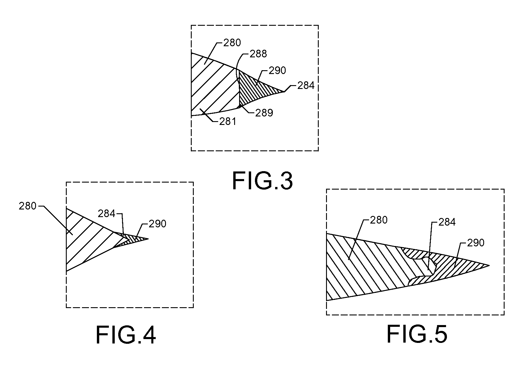
FIG. 3 is an exploded view of detail 3 of FIG. 2, illustrating a plating on a back side of the airfoil to produce a thin trailing edge, constructed in accordance with the present disclosure.
FIG. 4 is an exploded view similar to FIG. 3, but with the plating applied to the surface of an intact airfoil trailing edge, constructed in accordance with the present disclosure.
FIG. 5 is an exploded view similar to FIG. 4, but with the plating applied to the surface of a modified intact airfoil trailing edge, constructed in accordance with the present disclosure.
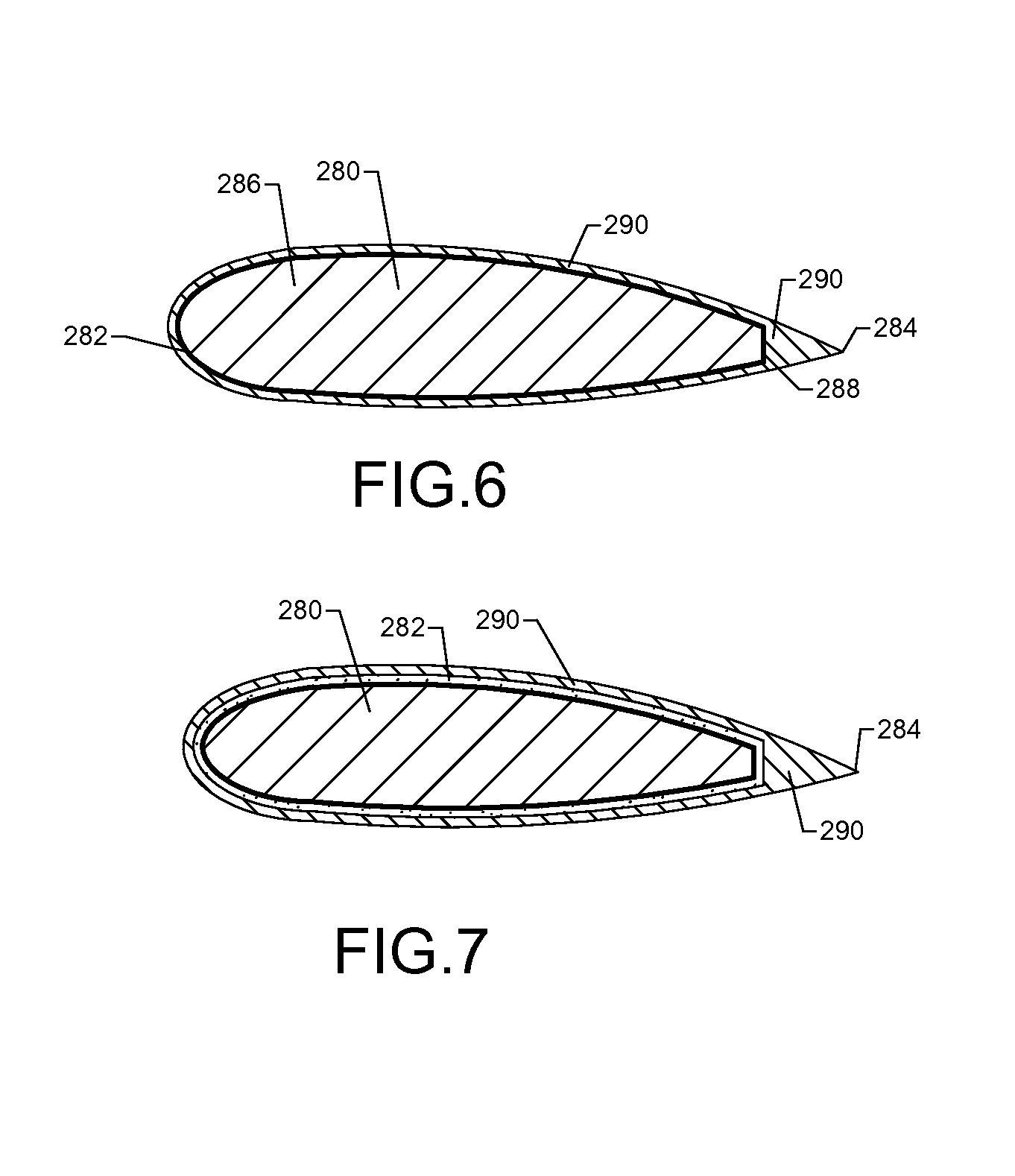
FIG. 6 is a cross-sectional view of the airfoil and similar to FIG. 2, but having the metal coating applied to all external surfaces of the airfoil, constructed in accordance with the present disclosure.
FIG. 7 is a cross-sectional view of the airfoil and similar to FIG. 6, but having an insulating layer between plating and the external surface of the airfoil, constructed in accordance with the present disclosure.
FIG. 8 is a flow chart illustrating steps involved in the fabrication of the airfoil, in accordance with a method of the present disclosure.
It should be understood that the drawings are not necessarily drawn to scale and that the disclosed embodiments are sometimes illustrated schematically and in partial views. It is to be further appreciated that the following detailed description is merely exemplary in nature and is not intended to limit the invention or the application and uses thereof. In this regard, it is to be additionally appreciated that the described embodiment is not limited to use with gas turbine engine airfoils. Hence, although the present disclosure is, for convenience of explanation, depicted and described as certain illustrative embodiments, it will be appreciated that it can be implemented in various other types of embodiments and in various other systems and environments.
DETAILED DESCRIPTION
Referring now to FIGS. 1 and 2, an airfoil 280 is shown. The airfoil 280 may be a rotating blade or a stator vane of a gas turbine engine. Alternatively, the airfoil 280 may be an airfoil for use in other applications such as, but not limited to, wind turbines, unmanned aerial vehicles (UAVs), micro-UAVs, race car down-force wings, missile wings, ballistic weapons, and guided weapons. The airfoil 280 may have a body portion 281, a leading edge 282, a trailing edge 284, a forward region 286, and a back side 288, as shown in FIG. 2. The leading edge 282 may be the portion of the airfoil 280 which first contacts (and separates) air, whereas the trailing edge 284 may be the portion of the airfoil where the separated air rejoins. By virtue of a high-modulus plating 290 at the trailing edge 284, the trailing edge 284 may have a minimum practical thickness which may advantageously eliminate or reduce undesirable bluff body close out shape at the trailing edge 284 as well as consequent drag-inducing flow separation and turbulent airflow (see further details below). Accordingly, the aerodynamic operation of the airfoil 280 may be substantially improved over current systems that lack such high-modulus platings at the airfoil trailing edge.
The body portion 281 of the airfoil 280 (i.e., the portion of the airfoil 280 which does not include the plating 290) may be formed from one or more lightweight and relatively low-modulus materials such as, but not limited to, aluminum, titanium, or an organic mesomorphous carbon (OMC) composite. As best shown in FIG. 3, the airfoil 280 may be truncated just prior to the start of the trailing edge 284 (i.e., at the back side 288) and the trailing edge 284 may be formed from the plating 290. The plating 290 may be formed from one or more layers of one or more high-modulus materials such as, but not limited to, nickel, iron, cobalt, and alloys of the foregoing elements comprising at least 50 wt. % of the alloy. The high-modulus nature of the material forming the plating 290 may enable a thinner trailing edge while maintaining necessary stiffness and resistance to flutter excitation and fatigue-induced cracking than could feasibly be produced with the lower-modulus materials forming the body portion 281 of the airfoil 280.
The plating 290 may be applied to a back surface 289 of the airfoil 280 by a metal deposition method apparent to those of ordinary skill in the art such as, but not limited to, electrolytic plating, electroless plating, brush plating, spray metal deposition, chemical vapor deposition, plasma vapor deposition, or a powder spray deposition process. The thickness of the plating 290 may range from about 0.001 inches (about 0.025 mm) near the tip of the trailing edge 284 to about 0.050 inches (about 1.3 mm) near the back side 288 of the airfoil 280, but other plating thicknesses may also apply. As one possible plating deposition method, the plating 290 may be initially deposited as a thick layer by one of the above-listed techniques and may be subsequently thinned and shaped in selected regions by a machining process or an abrasive grinding operation apparent to those of ordinary skill in the art. Such shaping techniques may enable the trailing edge 284 to be thinned and shaped to a minimum practical thickness.
As an alternative arrangement, the plating 290 may be deposited on an intact (non-truncated) trailing edge 284 of the airfoil 280 or it may be deposited on a modified intact trailing edge 284, as shown in FIGS. 4 and 5, respectively. In this way, the plating 290 may form an extension of the trailing edge 284 and may be thinned to a minimum practical thickness while maintaining necessary stiffness and fracture resistance.
The plating 290 may be applied to additional selected external surfaces of the airfoil 280 or to all external surfaces of the airfoil 280 such that the airfoil may be fully encased in the plating 290, as best shown in FIG. 6. Such an arrangement may be desired to eliminate an exposed bond-line edge between the material of the plating 290 and the material of the airfoil 280 which could otherwise present a potential delamination and peeling initiation point. If the airfoil 280 is encased in the plating 290, the plating 290 may be thinner near the forward regions 286 of the airfoil 280 and thicker near the back side 288, although other plating thickness variations may also be used.
In situations where the formation of strength-limiting or ductility-limiting phases (e.g., intermetallics) is expected at the interface between the surfaces of the airfoil 280 and the plating 290, or, in cases where galvanic corrosion at the interface of the airfoil 280 and the plating 290 is a concern, one or more insulating layers 292 may optionally be applied between the surfaces of the airfoil 280 and the plating 290 to produce a multi-layer structure, as shown in FIG. 7. The insulating layer 292 may prevent contact between the plating 290 and the surfaces of the airfoil 280 and thereby assist in preventing the formation of strength- or ductility-limiting phases and/or galvanic corrosion. The insulating layer 292 may be an adhesive, an epoxy material, a ceramic, or any other suitable material selected for such purposes by a skilled artisan. If necessary, the multi-layer structure shown in FIG. 7 may be brazed, transient liquid phase bonded, or diffusion bonded to form a more permanent joint between the airfoil 280 and the plating 290, as will be understood by those having ordinary skill in the art.
A method which may be employed for the fabrication of the airfoil 280 is shown in FIG. 8. Beginning with a first block 295, the airfoil 280 may be formed with a truncated trailing edge (see FIG. 3), an intact trailing edge (see FIG. 4), or a modified intact trailing edge (see FIG. 5) using a low-modulus material such as, but not limited to, aluminum, titanium, or composite material. Optionally, an insulating layer 292 may be applied to the surfaces of the airfoil 280 which are to be plated with the plating 290 according to an optional block 297. Whether or not an insulating layer 292 is applied, the plating 290, consisting of a high-modulus material, may be applied to selected surfaces of the airfoil 280 according to a block 299, as shown. The plating 290 may be applied by known metal deposition processes including, but not limited to, electrolytic plating, electroless plating, brush plating, spray metal deposition, chemical vapor deposition, plasma vapor deposition, or a powder spray deposition process. In this way, a trailing edge 284 may be built up on the back surface 289 of the airfoil 280 (see FIG. 3), or, the plating 290 may be deposited as an extension of an existing airfoil trailing edge (see FIGS. 4-5). Furthermore, the plating 290 may be deposited on additional or all external surfaces of the airfoil (see FIG. 6). The plating 290 may either be directly deposited such that a thin trailing edge is formed or it may be thinned and/or shaped at the trailing edge 284 or other selected regions as desired by a machining or abrasive grinding operation according to an optional block 301.
INDUSTRIAL APPLICABILITY
The present disclosure introduces a strategy for applying a thin plating of a high-modulus material to the trailing edge of an airfoil that is formed from a relatively low-modulus material to significantly improve the stiffness of the trailing edge, while allowing thinner practical trailing edges to be formed. Such stiffening of airfoil trailing edges, which are exposed to high-velocity airflow, pressure, and velocity pulses during operation, may improve the trailing edge fatigue life for a given thickness or may provide at least an equivalent fatigue life at reduced trailing edge thicknesses compared with current low-modulus airfoil materials. This technology may find wide industrial applicability in a wide range of areas including, but not limited to, gas turbine engines, unmanned aerial vehicles (UAVs), micro-UAVs, wind turbines, race car down-force wings, missile wings, ballistic weapons, and guided weapons.
* * * * *
D00000
D00001
D00002
D00003
D00004
XML
uspto.report is an independent third-party trademark research tool that is not affiliated, endorsed, or sponsored by the United States Patent and Trademark Office (USPTO) or any other governmental organization. The information provided by uspto.report is based on publicly available data at the time of writing and is intended for informational purposes only.
While we strive to provide accurate and up-to-date information, we do not guarantee the accuracy, completeness, reliability, or suitability of the information displayed on this site. The use of this site is at your own risk. Any reliance you place on such information is therefore strictly at your own risk.
All official trademark data, including owner information, should be verified by visiting the official USPTO website at www.uspto.gov. This site is not intended to replace professional legal advice and should not be used as a substitute for consulting with a legal professional who is knowledgeable about trademark law.