Weightlifting rack assembly and wall mount bracket for a weightlifting rack assembly
Henniger , et al.
U.S. patent number 10,226,661 [Application Number 16/043,805] was granted by the patent office on 2019-03-12 for weightlifting rack assembly and wall mount bracket for a weightlifting rack assembly. This patent grant is currently assigned to Coulter Ventures LLC. The grantee listed for this patent is Coulter Ventures LLC. Invention is credited to Nash Dunahay, William Henniger.


| United States Patent | 10,226,661 |
| Henniger , et al. | March 12, 2019 |
Weightlifting rack assembly and wall mount bracket for a weightlifting rack assembly
Abstract
An upper wall mount bracket configured for use with a foldable weightlifting rack assembly including a central panel, a top wall mount panel and a bottom wall mount panel. The top wall mount panel and the bottom wall mount panel are substantially planar and offset from the central panel. The top wall mount panel and the bottom mount panel are positionable to overlie a wall surface, and including at least one slot extending therethrough configured to receive a fastener therethrough to, in turn, couple the upper wall mount bracket to the wall surface. The central panel has a first side mounting region proximate to a first end thereof and a second side mounting region proximate a second end thereof. An upper rack mount assembly may be configured for use in association with the foldable weightlifting rack assembly and the upper wall mount bracket.
| Inventors: | Henniger; William (Columbus, OH), Dunahay; Nash (Gahanna, OH) | ||||||||||
|---|---|---|---|---|---|---|---|---|---|---|---|
| Applicant: |
|
||||||||||
| Assignee: | Coulter Ventures LLC (Columbus,
OH) |
||||||||||
| Family ID: | 64096411 | ||||||||||
| Appl. No.: | 16/043,805 | ||||||||||
| Filed: | July 24, 2018 |
Prior Publication Data
| Document Identifier | Publication Date | |
|---|---|---|
| US 20180326250 A1 | Nov 15, 2018 | |
Related U.S. Patent Documents
| Application Number | Filing Date | Patent Number | Issue Date | ||
|---|---|---|---|---|---|
| 15801638 | Nov 2, 2017 | ||||
| Current U.S. Class: | 1/1 |
| Current CPC Class: | A63B 23/0405 (20130101); F16M 13/02 (20130101); A63B 71/0036 (20130101); A63B 21/4035 (20151001); A63B 23/1218 (20130101); A63B 21/169 (20151001); A63B 21/078 (20130101); A63B 21/068 (20130101); A63B 2210/50 (20130101); A63B 2210/00 (20130101); A63B 21/0724 (20130101); A63B 2023/0411 (20130101); A63B 21/0628 (20151001) |
| Current International Class: | A63B 21/00 (20060101); A63B 23/04 (20060101); A63B 21/068 (20060101); A63B 21/072 (20060101); A63B 21/078 (20060101); A63B 71/00 (20060101); A63B 23/12 (20060101); F16M 13/02 (20060101) |
References Cited [Referenced By]
U.S. Patent Documents
| 2855200 | October 1958 | Blickman |
| 4961295 | October 1990 | Kosch, Sr. |
| 5046722 | September 1991 | Antoon |
| 5273506 | December 1993 | Dawson, Jr. |
| 6116550 | September 2000 | Forbes |
| 7316379 | January 2008 | Graham |
| 7523907 | April 2009 | Chen |
| 9192799 | November 2015 | Alenaddaf |
| 9308410 | April 2016 | Beaver |
| 9333387 | May 2016 | Hopperstad |
| 9409048 | August 2016 | Hopperstad |
| 9498670 | November 2016 | Hopperstad |
| 9517382 | December 2016 | Payne |
| 9649525 | May 2017 | Hopperstad |
| 9700761 | July 2017 | Beaver |
| 9844691 | December 2017 | Hopperstad |
| 9993678 | June 2018 | Hopperstad |
| 2003/0222041 | December 2003 | Hong |
| 2006/0065800 | March 2006 | Bremmon |
| 2006/0145038 | July 2006 | Chen |
| 2009/0105052 | April 2009 | Dalebout et al. |
| 2010/0044536 | February 2010 | Huang |
| 2010/0048368 | February 2010 | Donofrio |
| 2010/0171017 | July 2010 | Chang |
| 2014/0166834 | June 2014 | Kuroyanagi |
| 2015/0264823 | September 2015 | Shirley |
| 2015/0290488 | October 2015 | Hopperstad |
| 2016/0250515 | September 2016 | Hopperstad |
| 2016/0338512 | November 2016 | Royak |
| 2016/0339291 | November 2016 | Hopperstad |
| 2017/0065844 | March 2017 | Hopperstad |
| 2017/0189736 | July 2017 | Martin |
| 2017/0209733 | July 2017 | Beaver et al. |
| 2017/0239512 | August 2017 | Brasch et al. |
| 2017/0246490 | August 2017 | Hopperstad |
| 2018/0104522 | April 2018 | Hopperstad |
| 2018/0142832 | May 2018 | Inouye |
| 2018/0153305 | June 2018 | Haines |
| 2018/0178051 | June 2018 | Shaw, Jr. |
| 2400205 | Dec 2011 | EP | |||
| 2008054720 | May 2008 | WO | |||
| 2009003280 | Jan 2009 | WO | |||
Other References
|
Rogue product advertisement dated Dec. 3, 2015 (redacted). cited by applicant . Rogue fitness product video screenshots from <https://www.youtube.com/watch?v=TRpmZ68p5Hw>, dated Sep. 19, 2017. cited by applicant . Gorila Fitness product advertisement dated Apr. 16, 2018 (redacted). cited by applicant . Bulldog Gear product advertisement dated Jan. 11, 2018. cited by applicant . Pure Strength product listing dated Sep. 6, 2018 from <https://www.pure-strength.com/collections/slim-gym-utility-plate>. cited by applicant . Titan Fitness product listing dated Sep. 6, 2018 from <https://www.titan.fitness/t-3-folding-power-rack-stringers.html>. cited by applicant . Titan Fitness product listing dated Sep. 6, 2018 from <https://www.titan.fitness/41-inch-deep-folding-wall-mount-rack.html&g- t; (product known to be available as of Mar. 2, 2016). cited by applicant. |
Primary Examiner: Urbiel Goldner; Gary D
Attorney, Agent or Firm: Banner & Witcoff, Ltd.
Parent Case Text
CROSS-REFERENCE TO RELATED APPLICATION
This application is a continuation of, and claims priority to, U.S. patent application Ser. No. 15/801,638, filed Nov. 2, 2017, which prior application is incorporated by reference herein.
Claims
What is claimed is:
1. A weightlifting assembly, comprising: a first wall mount bracket configured for mounting to a wall surface, comprising: a first central panel having an inner surface configured to face the wall surface and an outer surface opposite the inner surface, the first central panel having a first mounting region and a second mounting region spaced from each other along the first central panel; a first top wall mount panel located above the first central panel and configured to overlie the wall surface; a first bottom wall mount panel located below the first central panel and configured to overlie the wall surface, wherein the first top and bottom wall mount panels are offset from the first central panel in a first direction perpendicular to the outer surface and the inner surface of the first central panel, wherein the first top wall mount panel and the first bottom wall mount panel have a plurality of first slots that are respectively elongated along a length of each of the first top and bottom wall mount panels and are respectively arranged sequentially along the lengths of the first top and bottom wall mount panels, wherein the plurality of first slots are configured to receive first wall mount fasteners therethrough to couple the first wall mount bracket to the wall surface; and first offset panels respectively extending between the first central panel and the first top wall mount panel and between the first central panel and the first bottom wall mount panel, the first offset panels being respectively angled to each of the first central panel and the first top and bottom wall mount panels; a second wall mount bracket configured for mounting to the wall surface at a location below the first wall mount bracket and spaced from the first wall mount bracket, comprising: a second central panel having an inner surface configured to face the wall surface and an outer surface opposite the inner surface, the second central panel having a third mounting region and a fourth mounting region spaced from each other along the second central panel; a second top wall mount panel located above the second central panel and configured to overlie the wall surface; a second bottom wall mount panel located below the second central panel and configured to overlie the wall surface, wherein the second top and bottom wall mount panels are offset from the second central panel in the first direction, wherein the second top wall mount panel and the second bottom wall mount panel have a plurality of second slots that are respectively elongated along a length of each of the second top and bottom wall mount panels and are respectively arranged sequentially along the lengths of the second top and bottom wall mount panels, wherein the plurality of second slots are configured to receive additional wall mount fasteners therethrough to couple the second wall mount bracket to the wall surface; and second offset panels respectively extending between the second central panel and the second top wall mount panel and between the second central panel and the second bottom wall mount panel, the second offset panels being respectively angled to each of the second central panel and the second top and bottom wall mount panels; and a weightlifting rack assembly connected to the first wall mount bracket and the second wall mount bracket, the weightlifting rack assembly comprising a first bracket connected to the first central panel of the first wall mount bracket at the first mounting region by a first fastener, a second bracket connected to the first central panel of the first wall mount bracket at the second mounting region by a second fastener, a third bracket connected to the second central panel of the second wall mount bracket at the third mounting region by a third fastener, and a fourth bracket connected to the second central panel of the second wall mount bracket at the fourth mounting region by a fourth fastener, wherein the first top and bottom wall mount panels being offset from the first central panel is configured to create a first space between the inner surface of the first central panel and the wall surface, to provide clearance for the first and second fasteners, and wherein the second top and bottom wall mount panels being offset from the second central panel is configured to create a second space between the inner surface of the second central panel and the wall surface, to provide clearance for the third and fourth fasteners.
2. The weightlifting assembly of claim 1, wherein the first offset panels are respectively oblique to the first central panel and the first top and bottom wall mount panels, and wherein the second offset panels are respectively oblique to the second central panel and the second top and bottom wall mount panels.
3. The weightlifting assembly of claim 1, wherein the first mounting region comprises a first opening in the first central panel receiving the first fastener, the second mounting region comprises a second opening in the first central panel receiving the second fastener, the third mounting region comprises a third opening in the second central panel receiving the third fastener, and the fourth mounting region comprises a fourth opening in the second central panel receiving the fourth fastener.
4. The weightlifting assembly of claim 1, wherein each of the first side rack assembly and the second side rack assembly is moveable by pivoting between a folded configuration adjacent to the wall surface and an articulated configuration distal from the wall surface.
5. The weightlifting assembly of claim 1, wherein the weightlifting rack assembly further comprises a plurality of frame members including a first vertical member and a second vertical member spaced from each other, a first cross bar connecting the first bracket to the first vertical member, a second cross bar connecting the second bracket to the second vertical member, a third cross bar connecting the third bracket to the first vertical member, and a fourth cross bar connecting the fourth bracket to the second vertical member.
6. The weightlifting assembly of claim 5, wherein the first and second vertical members are configured to engage a ground surface that junctures with the wall surface.
7. The weightlifting assembly of claim 5, wherein the plurality of frame members further comprises a cross member connecting the first vertical member to the second vertical member.
8. The weightlifting assembly of claim 1, wherein the plurality of first slots are elongated along the length of each of the first top and bottom wall mount panels, and the plurality of second slots are elongated along the length of each of the second top and bottom wall mount panels.
9. A method for mounting a weightlifting assembly, comprising: mounting a first wall mount bracket to a wall surface at a first height, the first wall mount bracket comprising: a first central panel having an inner surface facing the wall surface when the first wall mount bracket is mounted to the wall surface, and an outer surface opposite the inner surface, the first central panel having a first mounting region and a second mounting region spaced from each other along the first central panel; a first top wall mount panel located above the first central panel, the first top wall mount panel overlying the wall surface when mounted; a first bottom wall mount panel located below the first central panel, the first bottom wall mount panel overlying the wall surface when mounted, wherein the first top and bottom wall mount panels are offset from the first central panel such that a first space is defined between the inner surface of the first central panel and the wall surface when the first wall mount bracket is mounted to the wall surface, wherein the first top wall mount panel and the first bottom wall mount panel have a plurality of first slots that are respectively arranged sequentially along a length of each of the first top and bottom wall mount panels; and first offset panels respectively extending between the first central panel and the first top wall mount panel and between the first central panel and the first bottom wall mount panel, the first offset panels being respectively angled to each of the first central panel and the first top and bottom wall mount panels, wherein mounting the first wall mount bracket to the wall surface comprises inserting first wall mount fasteners through the plurality of first slots, such that the first wall mount fasteners engage the wall surface to mount the first wall mount bracket to the wall surface; mounting a second wall mount bracket to the wall surface at a second height that is lower than the first height, such that the second wall mount bracket is located below and spaced from the first wall mount bracket, the second wall mount bracket comprising: a second central panel having an inner surface facing the wall surface when the second wall mount bracket is mounted to the wall surface, and an outer surface opposite the inner surface, the second central panel having a third mounting region and a fourth mounting region spaced from each other along the second central panel; a second top wall mount panel located above the second central panel, the second top wall mount panel overlying the wall surface when mounted; a second bottom wall mount panel located below the second central panel, the second bottom wall mount panel overlying the wall surface when mounted, wherein the second top and bottom wall mount panels are offset from the second central panel such that a second space is defined between the inner surface of the second central panel and the wall surface when the second wall mount bracket is mounted to the wall surface, wherein the second top wall mount panel and the second bottom wall mount panel have a plurality of second slots that are respectively arranged sequentially along a length of each of the second top and bottom wall mount panels; and second offset panels respectively extending between the second central panel and the second top wall mount panel and between the second central panel and the second bottom wall mount panel, the second offset panels being respectively angled to each of the second central panel and the second top and bottom wall mount panels, wherein mounting the second wall mount bracket to the wall surface comprises inserting second wall mount fasteners through the plurality of second slots, such that the second wall mount fasteners engage the wall surface to mount the second wall mount bracket to the wall surface; connecting a weightlifting rack assembly to the first wall mount bracket and the second wall mount bracket, the weightlifting rack assembly comprising a first bracket, a second bracket, a third bracket, a fourth bracket, and a plurality of frame members including a first vertical member and a second vertical member spaced from each other, a first cross bar connecting the first bracket to the first vertical member, a second cross bar connecting the second bracket to the second vertical member, a third cross bar connecting the third bracket to the first vertical member, and a fourth cross bar connecting the fourth bracket to the second vertical member, wherein the weightlifting rack assembly is connected to the first and second wall mount brackets by connecting the first bracket to the first wall mount bracket at the first mounting region on the first central panel, connecting the second bracket to the first wall mount bracket at the second mounting region on the first central panel, connecting the third bracket to the second wall mount bracket at the third mounting region on the second central panel, and connecting the fourth bracket to the second wall mount bracket at the fourth mounting region on the second central panel.
10. The method of claim 9, wherein the first bracket is connected to the first central panel by a first fastener, the second bracket is connected to the first central panel by a second fastener, the third bracket is connected to the second central panel by a third fastener, and the fourth bracket is connected to the second central panel by a fourth fastener.
11. The method of claim 10, wherein the first mounting region comprises a first opening in the first central panel receiving the first fastener, the second mounting region comprises a second opening in the first central panel receiving the second fastener, the third mounting region comprises a third opening in the second central panel receiving the third fastener, and the fourth mounting region comprises a fourth opening in the second central panel receiving the fourth fastener.
12. The method of claim 9, wherein the weightlifting rack assembly is foldable and comprises a first side rack assembly including the first bracket, the first cross bar, the third bracket, the third cross bar, and the first vertical member, and a second side rack assembly including the second bracket, the second cross bar, the fourth bracket, the fourth cross bar, and the second vertical member, wherein the first, second, third, and fourth brackets are pivot brackets, and wherein the first side rack assembly is foldable by pivoting at the first and third brackets, and the second side rack assembly is foldable by pivoting at the second and fourth brackets.
13. The method of claim 12, further comprising pivoting the first side rack assembly and the second side rack assembly from folded configurations adjacent to the wall surface to articulated configurations distal from the wall surface, and connecting a central cross member between the first and second side rack assemblies to fix the first and second side rack assemblies in the articulated configurations.
14. The method of claim 9, further comprising assembling the plurality of frame members and the first, second, third, and fourth brackets to form the weightlifting rack assembly.
15. The method of claim 9, wherein the first and second vertical members engage a ground surface that junctures with the wall surface.
16. The method of claim 9, wherein the first offset panels are respectively oblique to the first central panel and the first top and bottom wall mount panels, and wherein the second offset panels are respectively oblique to the second central panel and the second top and bottom wall mount panels.
Description
BACKGROUND OF THE DISCLOSURE
1. Field of the Disclosure
The disclosure relates in general to a weightlifting equipment, and more particularly, to weightlifting racks and to structures for coupling weightlifting racks to a wall surface.
2. Background Art
A staple of any gym is a weightlifting rack assembly. The weightlifting rack assembly is used to support weights for many weightlifting exercises, such as, for example, squatting, pressing, among others. Additionally, weightlifting rack assemblies can be used for body weight exercises, including, for example, chin-ups, pullups and the like. Further, additional structures can be coupled thereto for storage, and for the performance of yet further exercises.
Increasingly, athletes are converting living spaces or, for example, garage spaces into home gyms. To increase versatility, a number of foldable or collapsible weightlifting rack assemblies have been developed. Typically, these foldable or collapsible assemblies are attached to a wall surface (such as a garage wall). They can be folded or collapsed to permit the use of the garage, to, for example, store a vehicle, when the assemblies are not in use. That is, they can be folded to be quite flush with the wall surface to which they are attached.
Problematically, however, to properly secure the assembly to the wall surface, it is often necessary to secure studs to the wall surface to span between the vertical wall studs. Problematically, the use of additional studs on the wall surface increases the footprint of the assembly, which is problematic when space is at a premium. Additionally, where it is desirable to couple the assembly to vertical studs directly, there is often a limitation as to the placement of the assembly. And, often, the wall studs are too narrow to be used to support the assembly.
SUMMARY OF THE DISCLOSURE
The disclosure is directed, in one aspect to a foldable weightlifting rack assembly mountable to a wall surface. The assembly includes an upper wall mount bracket, a lower wall mount bracket, a first side rack assembly and a second side rack assembly. The upper wall mount bracket has a central panel, a top wall mount panel and a bottom wall mount panel. The top wall mount panel and the bottom wall mount panel are substantially planar and offset from the central panel. The top wall mount panel and the bottom mount panel are positionable to overlie a wall surface, and including at least one slot extending therethrough configured to receive a fastener therethrough to, in turn, couple the upper wall mount bracket to the wall surface. The lower wall mount bracket has a central panel, a top wall mount panel and a bottom wall mount panel. The top wall mount panel and the bottom wall mount panel are substantially planar and offset from the central panel. The top wall mount panel and the bottom mount panel are positionable to overlie a wall surface, and including at least one slot extending therethrough configured to receive a fastener therethrough to, in turn, couple the upper wall mount bracket to the wall surface.
The first side rack assembly has a main bar with an upper end and a lower end. An upper cross bar is proximate the upper end, and a lower cross bar is proximate the lower end. The upper cross bar is pivotably coupled to the upper wall mount bracket proximate a first end thereof. The lower cross bar is pivotably coupled to the lower wall mount bracket proximate a first end thereof.
The second side rack assembly has a main bar with an upper end and a lower end, an upper cross bar proximate the upper end and a lower cross bar proximate the lower end. The upper cross bar is pivotably coupled to the upper wall mount bracket proximate a second end thereof. The lower cross bar is pivotably coupled to the lower wall mount bracket proximate a second end thereof.
In some configurations, the main bar of the first side rack is substantially parallel to the central panel of the upper wall mount and substantially parallel to the central panel of the of the lower wall mount.
In some configurations, the upper wall mount bracket further includes a first offset panel extending between the top wall mount panel and the central panel. The first offset panel is oblique to each of the top wall mount panel and the central panel.
In some configurations, the upper wall mount bracket further includes a second offset panel extending between the central panel and the lower wall mount panel. The second offset panel is oblique to each of the central panel and the bottom wall mount panel.
In some configurations, the central panel of the upper wall mount bracket further includes a first side mounting region proximate the first end and a second side mounting region proximate the second end. The assembly further includes a first side upper rack pivot bracket and a second side upper rack pivot bracket. The first side upper rack pivot bracket coupled to the first side mounting region. The first side upper rack pivot bracket comprises a base with an upper pivot wall and a lower pivot wall, with the upper cross bar of the first side rack being pivotably coupled to the upper and lower pivot walls of the first side upper rack pivot bracket. The second side upper rack pivot bracket is coupled to the second side mounting region. The second side upper rack pivot bracket comprises a base with an upper pivot wall and a lower pivot wall, with the upper cross bar of the second side rack being pivotably coupled to the upper and lower pivot walls of the second side upper rack pivot bracket.
In some configurations, the base of the first side upper rack pivot bracket is coupled to the central panel of the upper wall mount bracket by a fastener. The base of the second side upper rack pivot bracket is coupled to the central panel of the upper wall mount bracket by a second fastener. A portion of each of the first and second fastener extending between a plane defined by the central panel and a plane defined by the top and bottom wall mount panels.
In some configurations, the lower wall mount bracket further includes a first offset panel extending between the top wall mount panel and the central panel, the first offset panel being oblique to each of the top wall mount panel and the central panel.
In some configurations, the lower wall mount bracket further includes a second offset panel extending between the central panel and the lower wall mount panel. The second offset panel is oblique to each of the central panel and the bottom wall mount panel.
In some configurations, the central panel of the lower wall mount bracket further includes a first side mounting region proximate the first end and a second side mounting region proximate the second end. The assembly further comprises a first side lower rack pivot bracket and a second side lower rack pivot bracket. The first side lower rack pivot bracket is coupled to the first side mounting region. The first side lower rack pivot bracket comprises a base with an upper pivot wall and a lower pivot wall, with the upper cross bar of the first side rack being pivotably coupled to the upper and lower pivot walls of the first side upper rack pivot bracket. The second side lower rack pivot bracket is coupled to the second side mounting region. The second side lower rack pivot bracket comprises a base with an upper pivot wall and a lower pivot wall, with the upper cross bar of the second side rack being pivotably coupled to the upper and lower pivot walls of the second side upper rack pivot bracket.
In some configurations, the base of the first side lower rack pivot bracket is coupled to the central panel of the upper wall mount bracket by a fastener. The base of the second side lower rack pivot bracket is coupled to the central panel of the upper wall mount bracket by a second fastener. A portion of each of the first and second fastener extending between a plane defined by the central panel and a plane defined by the top and bottom wall mount panels.
In another aspect of the disclosure, the disclosure is directed to an upper rack mount assembly configured for use in association with a foldable weightlifting rack assembly. The upper rack mount assembly comprises a upper wall mounting bracket, a first side upper rack pivot bracket and a second side upper rack pivot bracket. The upper wall mount bracket haw a central panel, a top wall mount panel and a bottom wall mount panel. The top wall mount panel and the bottom wall mount panel are substantially planar and offset from the central panel. The top wall mount panel and the bottom mount panel are positionable to overlie a wall surface, and include at least one slot extending therethrough configured to receive a fastener therethrough to, in turn, couple the upper wall mount bracket to the wall surface. The central panel has a first side mounting region proximate the first end and a second side mounting region proximate the second end.
The first side upper rack pivot bracket is coupled to the first side mounting region. The first side upper rack pivot bracket comprises a base with an upper pivot wall and a lower pivot wall, with the upper cross bar of the first side rack being pivotably coupled to the upper and lower pivot walls of the first side upper rack pivot bracket. The second side upper rack pivot bracket is coupled to the second side mounting region. The second side upper rack pivot bracket comprises a base with an upper pivot wall and a lower pivot wall, with the upper cross bar of the second side rack being pivotably coupled to the upper and lower pivot walls of the second side upper rack pivot bracket.
In some configurations, the base of the first side upper rack pivot bracket is coupled to the central panel of the upper wall mount bracket by a fastener. The base of the second side upper rack pivot bracket is coupled to the central panel of the upper wall mount bracket by a second fastener. A portion of each of the first and second fastener extend between a plane defined by the central panel and a plane defined by the top and bottom wall mount panels.
In some configurations, the plane defined by the central panel is substantially parallel with the plane defined by the top and bottom wall mount panels.
In some configurations, the top and bottom wall mount panels each have a plurality of slots between the first and second end thereof.
In some configurations, the upper wall mount bracket further includes a second offset panel extending between the central panel and the lower wall mount panel. The second offset panel being oblique to each of the central panel and the bottom wall mount panel.
In some configurations, the assembly further includes a first side handle opening positioned proximate the first side mounting region and a second side handle opening positioned proximate the second side mounting region.
In some configurations, the central panel, the top wall mount panel, the bottom wall mount panel, the first offset panel and the second offset panel each define a thickness that is substantially equal.
In some configurations, the first side upper rack pivot bracket and the second side upper rack pivot bracket are substantially identical.
In yet another aspect of the disclosure, the disclosure is directed to an upper wall mount bracket configured for use with a foldable weightlifting rack assembly. The upper wall mount bracket comprising a central panel, a top wall mount panel and a bottom wall mount panel. The top wall mount panel and the bottom wall mount panel being substantially planar and offset from the central panel. The top wall mount panel and the bottom mount panel being positionable to overlie a wall surface, and including at least one slot extending therethrough configured to receive a fastener therethrough to, in turn, couple the upper wall mount bracket to the wall surface. The central panel having a first side mounting region proximate the first end and a second side mounting region proximate the second end.
In some configurations, the upper wall mount bracket further includes a first offset panel extending between the top wall mount panel and the central panel. The first offset panel is oblique to each of the top wall mount panel and the central panel. Additionally, the upper wall mount bracket includes a second offset panel extending between the central panel and the lower wall mount panel. The second offset panel is oblique to each of the central panel and the bottom wall mount panel.
BRIEF DESCRIPTION OF THE DRAWINGS
The disclosure will now be described with reference to the drawings wherein:
FIG. 1 of the drawings is a perspective view of the foldable weightlifting rack assembly;
FIG. 2 of the drawings is a front elevational view of the foldable weightlifting rack assembly;
FIG. 3 of the drawings is a partial perspective view of the foldable weightlifting rack assembly, showing, in particular, the upper rack mount assembly;
FIG. 4 of the drawings is perspective view of the upper rack mount assembly;
FIG. 5 of the drawings is perspective view of the upper wall mount bracket;
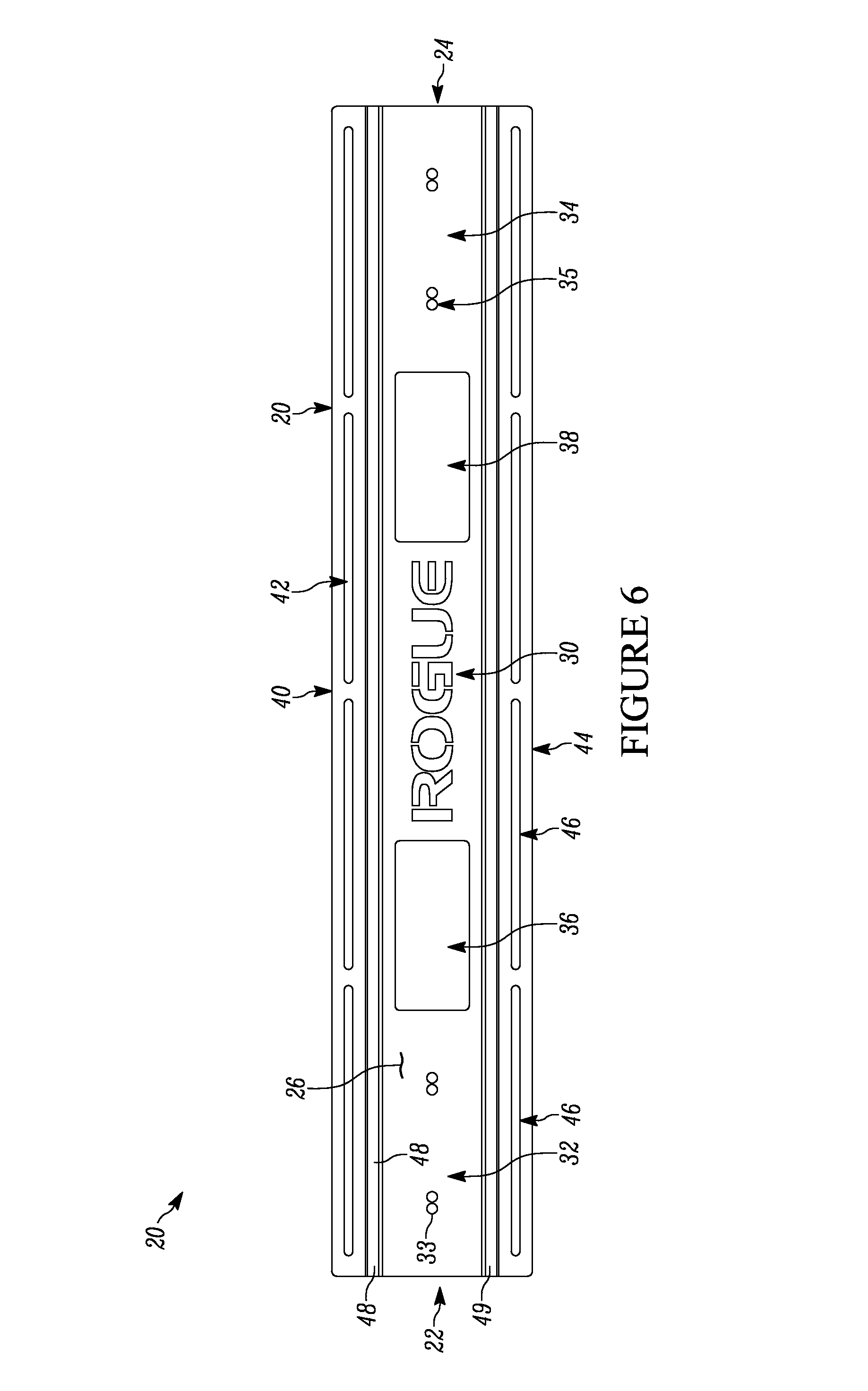
FIG. 6 of the drawings is a front elevational view of the upper wall mount bracket;
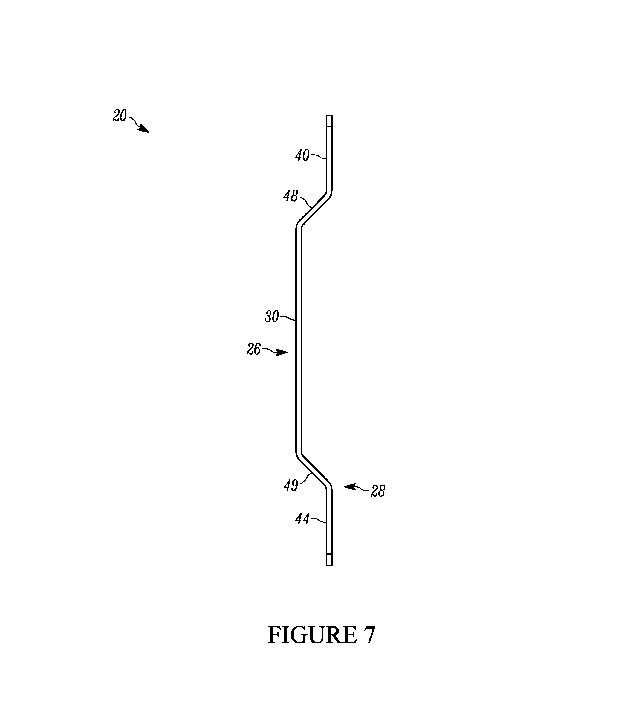
FIG. 7 of the drawings is side elevational view of the upper wall mount bracket;
FIG. 8 of the drawings is perspective view of the upper rack mount assembly; and
FIG. 9 of the drawings is perspective view of the upper wall mount bracket.
DETAILED DESCRIPTION OF THE DISCLOSURE
While this disclosure is susceptible of embodiment in many different forms, there is shown in the drawings and described herein in detail a specific embodiment(s) with the understanding that the present disclosure is to be considered as an exemplification and is not intended to be limited to the embodiment(s) illustrated.
It will be understood that like or analogous elements and/or components, referred to herein, may be identified throughout the drawings by like reference characters. In addition, it will be understood that the drawings are merely schematic representations of the invention, and some of the components may have been distorted from actual scale for purposes of pictorial clarity.
Referring now to the drawings and in particular to FIGS. 1 and 2, a foldable weightlifting rack assembly 10 is shown. The weightlifting rack 10 comprises an upper rack mount assembly 12, lower rack mount assembly 14, first side rack assembly 16, second side rack assembly 18, and cross bar assembly 19. With reference to FIGS. 1 and 3, the cross bar assembly 19 couples the first side rack assembly 16 and second side rack assembly 18. Removal of the cross bar assembly 19, as well as the pin members that are extended therethrough, allows rotational movement of the first side rack assembly 16 and second side rack assembly 18 to direct the first and second side rack assemblies between a folded and an articulated configuration.
Shown in FIGS. 4 through 7, the upper rack mount assembly 12 comprises upper wall mount bracket 20, first side upper rack pivot bracket 50, second side upper rack pivot bracket 150, wall mount fasteners 80, pivot bracket mount fasteners 82, and pivot pins 84. The upper wall mount bracket 20 comprises a first side end 22, second side end 24, outer surface 26, inner surface 28, central panel 30, top wall mount panel 40, bottom wall mount panel 44, first end offset panels 48, and second offset panels 49. Further, the top wall mount panel 40 and bottom wall mount panel 44 define a plurality of slots 42, 46 extending substantially through the outer surface 26 and inner surface 28. The central panel 30 further comprises first side mounting region 32, second side mounting region 34, first side handle openings 36 and second side handle openings 38, with the first side mounting region 32 and second side mounting region 34 both defining a plurality of openings 33, 35 extending substantially through the outer surface 26 and inner surface 28. It is contemplated that the upper wall mount bracket (as well as the lower wall mount bracket) are formed from a single material, wherein the various panels have substantially the same thickness therethrough.
The first end 22 and second end 24 are substantially opposite one another with the outer surface 26 and inner surface 28 extending substantially between each end. The outer surface 26 and inner surface are substantially opposite one another in reference to the upper wall mount bracket 20 with the outer surface 26 facing substantially opposite the inner surface 24. The first side mounting region 32 of the central panel is proximate to the first side end 22 and the second side mounting region 34 of the central panel 30 is proximate to the second side end 24. Openings 33 of the first side mounting region 32, in the configuration shown, are separated by a general amount of material along the central panel 30, being proximate to the first side end 22 generally more than the first side handle opening 36. Openings 35 of the second side mounting region 34, in the configuration shown, are separated by a general amount of material along the central panel 30, being proximate to the second side end 24 generally more than the second side handle opening 38. The first side handle opening 36 and the second side handle opening 38 extend generally through the outer surface 26 and inner surface 28 and are proximate to the central axis of the upper rack mount assembly 12. It is to be understood the size of the openings 33, 35, the first side handle opening 36, and second side handle opening 38 as well as the distance of separation between them along the upper wall mount bracket 20 in the exemplary figure are variable and subject to change in contemplated configurations of the design.
The central panel 30, top wall mount panel 40, and bottom wall mount panel 44 extend from the first side end 22 to the second side end 24 and are parallel in reference to one another. In the configuration shown, the top wall mount panel 40 and bottom wall mount panel 44 are substantially coplanar in reference to one another such that a suitably flat surface mated to the inner surface 28 of the top wall mount panel 40 will be substantially mated to the inner surface 28 of the bottom wall mount panel 44. In the vertical plane, the central panel is substantially between the top wall mount panel 40 and bottom wall panel 44, with the bottom wall mount panel substantially beneath the central panel 30 and top wall mount panel 40. In the configuration shown, the plurality of slots 42 defined by the top wall mount panel 40 and the plurality of the slots 46 defined by the bottom wall mount panel 44 extend from first end 22 towards second end 24. It is to be understood the number of slots 42, 46 and the sizing in reference to the horizontal and vertical distance are variable and subject to change in contemplated configurations of the design.
The central panel 30 and top wall mount panel 40 are coupled through the first offset panel 48. In the configuration shown, the first offset panel 48 is oblique to each of the parallel surface of the central panel 30 and top wall mount panel 40. It is to be understood the angle of offset of the first offset panel 48 may be of any suitable amount such that the central panel 30 and top wall mount panel 40 are separated with reference to the horizontal plane. The central panel 30 and bottom wall mount panel 44 are coupled through the second offset panel 49. In the configuration shown, the second offset panel 49 is oblique to each of the central panel 30 and bottom wall mount panel 44. It is to be understood in contemplated configurations of the design, the angle of offset of the second offset panel 49 may be of any suitable amount such that the central panel 30 and bottom wall mount panel 44 are separated with reference to the horizontal plane, including the central panel 30 being moved in such a way that the top wall mount panel 40 and bottom wall mount panel 44 are switched in reference to the horizontal plane.
The first side upper rack pivot bracket 50, shown in FIG. 4, comprises base 52, upper pivot wall 54, and lower pivot wall 56. The base 52 comprise outer surface 60, inner surface 61, central region 62, first side wing region 64, second side wing region 66, first side mounting opening 68, and second side mounting opening 69. The upper pivot wall 54 comprise inner surface 70, outer surface 71, and pivot opening 72. The lower pivot wall 56 comprise inner surface 73, outer surface 74, and pivot opening 75. It is to be understood the base 52 connects the upper pivot wall 54 and lower pivot wall 56 through extension of the central region 62. In the exemplary figure, the upper pivot wall 54 and lower pivot wall 56 are generally parallel in reference to one another, while other configurations are contemplated.
The inner surface 61 of the base 52 is generally mated to the outer surface 26 of the upper wall mount bracket 20 with the outer surface 60 generally opposite the inner surface 61. Generally, the base 52 extends from first side wing region 64, through central region 62, and to the second side wing region 66. The first side wing region 64 defines opening first side mounting opening 68 and the second side wing region 66 defines opening second side mounting opening 69. It is to be understood the wing regions of the base 52 are connected to the central region 62 of the base. The mounting openings 68, 69 are coaxially aligned with the openings 33 of the first side mounting region 32 of the upper wall mount bracket 20. It is to be understood any alteration of the position of the openings 33 of the upper wall mount bracket is to be substantially similar to alterations in the positions of the openings 68, 69. Further, the mounting openings 68, 69 in the configuration shown are of a variable size that is subject to change in contemplated configurations.
The inner surface 70 and outer surface 71 of the upper pivot wall 54 are generally opposite one another with pivot opening 72 defined by the upper pivot wall 54 and extending through the inner surface 70 and outer surface 71. The inner surface 73 and outer surface 74 of the lower pivot wall 56 are generally opposite one another with pivot opening 75 defined by the lower pivot wall 56 and extending through the inner surface 73 and outer surface 74. The inner surface 70 of upper pivot wall 54 and inner surface 73 of the lower pivot wall 56 generally face one another in such a way the corresponding outer surfaces 71, 74 face opposite in reference to one another. The pivot openings 72, 75 of the upper pivot wall 54 and lower pivot wall 56 are generally coaxial in reference to one another. It is to be understood the sizing of the openings 72, 75 in the exemplary figure is variable and subject to change in contemplated configurations of the design.
The second side upper rack pivot bracket 150, shown in FIG. 4, comprise base 152, upper pivot wall 154, and lower pivot wall 156. The base 152 comprise outer surface 160, inner surface 161, central region 162, first side wing region 164, second side wing region 166, first side mounting opening 168, and second side mounting opening 169. The upper pivot wall 154 comprise inner surface 170, outer surface 171, and pivot opening 172. The lower pivot wall 156 comprise inner surface 173, outer surface 174, and pivot opening 175. It is to be understood the base 152 connects the upper pivot wall 154 and lower pivot wall 156 through extension of the central region 162. In the exemplary figure, the upper pivot wall 154 and lower pivot wall 156 are generally parallel in reference to one another, but is subject to change in contemplated configurations and future iterations of the design.
The inner surface 161 of the base 152 is mated to the outer surface 126 of the upper wall mount bracket 20 with the outer surface 160 generally opposite the inner surface 161. Generally, the base 152 extends from first side wing region 164, through central region 162, and to the second side wing region 166. The first side wing region 164 defines opening first side mounting opening 168 and the second side wing region 166 defines opening second side mounting opening 169. It is to be understood the wing regions of the base 152 are connected to the central region 162 of the base. The mounting openings 168, 169 are coaxially aligned with the openings 35 of the second side mounting region 34 of the upper wall mount bracket 20. It is to be understood any alteration of the position of the openings 133 of the upper wall mount bracket is to be substantially similar to alterations in the positions of the openings 168, 169. Further, the mounting openings 168, 169 in the exemplary figure are of a variable size that is subject to change in contemplated configurations.
The inner surface 170 and outer surface 171 of the upper pivot wall 154 are generally opposite one another with pivot opening 172 defined by the upper pivot wall 154 and extending through the inner surface 170 and outer surface 171. The inner surface 173 and outer surface 174 of the lower pivot wall 156 are opposite one another with pivot opening 175 defined by the lower pivot wall 156 and extending through the inner surface 173 and outer surface 174. The inner surface 170 of upper pivot wall 154 and inner surface 173 of the lower pivot wall 156 generally face one another in such a way the corresponding outer surfaces 171, 174 face opposite in reference to one another. The pivot openings 172, 175 of the upper pivot wall 154 and lower pivot wall 156 are generally coaxial in reference to one another. It is to be understood the sizing of the openings 172, 175 in the exemplary figure is variable and subject to change in contemplated configurations of the design.
Shown in FIGS. 1 through 4, mounting and assembly of the upper rock mount assembly uses wall mount fasteners 80, pivot bracket mount fasteners 82, and pivot pins 84. The upper wall mount bracket 20, first side upper rack pivot bracket 50, and second side upper rack pivot bracket 150 in the exemplary figures are coupled together through pivot bracket mount fasteners 82. The pivot bracket mount fasteners 82 fit substantially and concentrically with the mounting openings 68, 69, 168, 169 of the upper rack pivot brackets and the openings 33, 35 of the upper wall mount bracket. The first side upper rack pivot bracket 50 and the second side upper rack pivot bracket 150 are generally aligned in reference to the vertical plan and separated along the horizontal plane by the upper wall mount bracket 20.
In the configuration shown, the first side upper rack pivot bracket 50 and the second side upper rack pivot bracket 150 mate to the upper wall mount bracket 20 by the pivot bracket mount fasteners. In the exemplary figure, the upper wall mount bracket 20 is generally coupled to the wall surface 700 by wall mount fasteners 80. The wall mount fasteners 80 couple the upper wall mount bracket 20 to wall surface 70 through slots 42, 46 of the top wall mount panel 40 and bottom wall mount panel 44 to the studs 702 of the wall surface 700. It is to be understood the wall mount fasteners 80 are aligned in such a way to provide a substantial enough force to limit vertical and horizontal movement of the upper wall mount bracket 20 while coupled to the wall surface 700, additionally resisting external forces. Pivot pins 84 couple to the first side upper rack pivot bracket 50 and second side upper rack pivot bracket 150 through the pivot openings 72, 75, 172, and 175. The pivots pins 84 are generally concentric to the openings and fit in such a way that rotational movement is not generally limited. It is to be understood the number of fasteners, as well as their sizing and method of attachment, used in the shown figures is exemplary and is subject to change in contemplated configurations of the design.
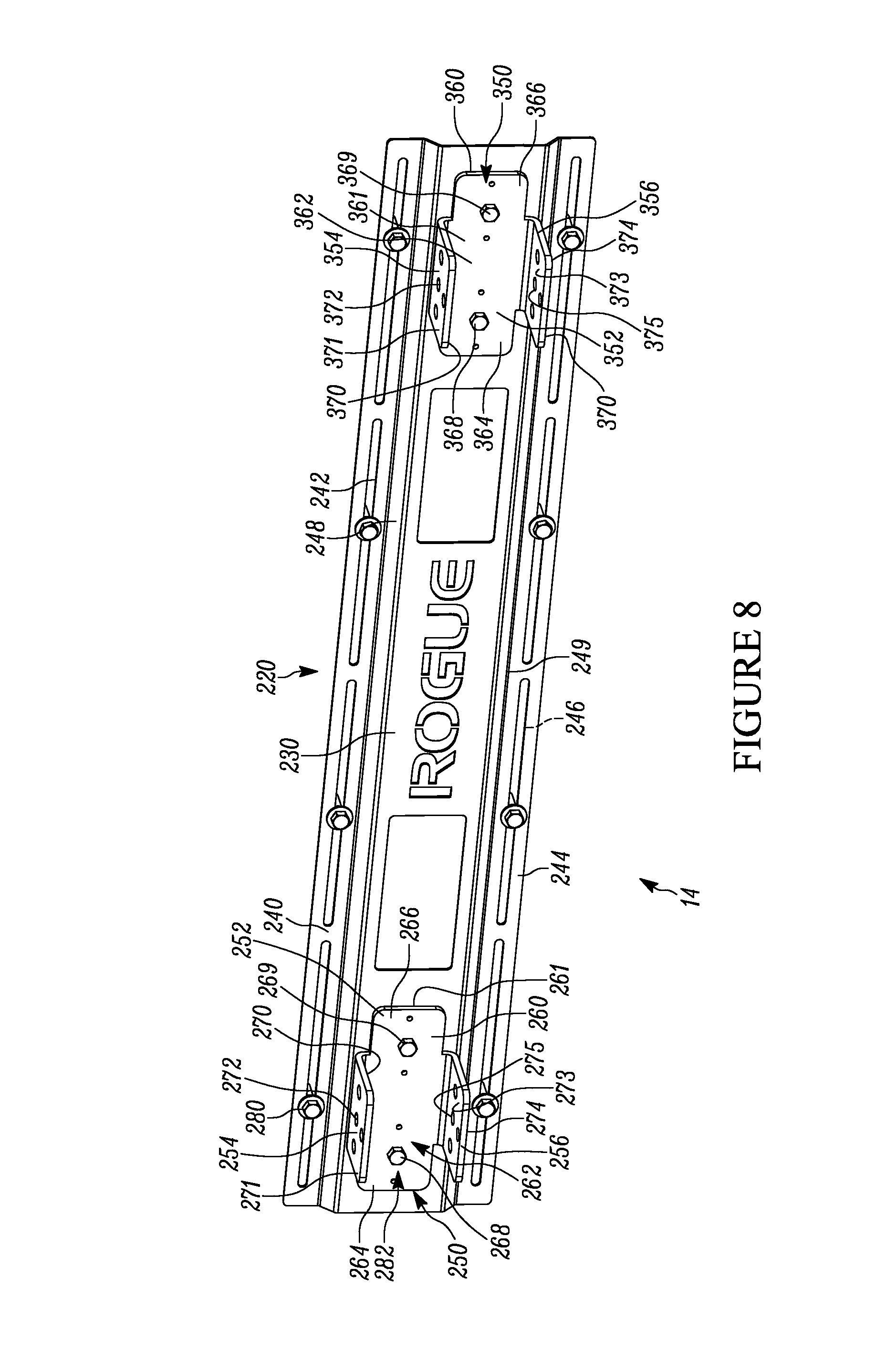
Shown in FIGS. 1, 2, 8 and 9, the lower rack mount assembly 14 is substantially identical to the upper rack mount assembly 12. As such, the same components have the same reference numbers augmented by 200. In particular, the lower rack mount assembly comprises lower wall mount bracket 220, first side lower rack pivot bracket 250, second side lower rack pivot bracket 350, wall mount fasteners 280, pivot bracket mount fasteners 282, and pivot pins 284. The lower wall mount bracket 220 comprises a first side end 222, second side end 224, outer surface 226, inner surface 228, central panel 230, top wall mount panel 240, bottom wall mount panel 244, first end offset panels 248, and second offset panels 249. Further, the top wall mount panel 240 and bottom wall mount panel 244 define a plurality of slots 242, 246 extending generally through the outer surface 226 and inner surface 228. The central panel 230 further comprises first side mounting region 232, second side mounting region 234, first side handle openings 236 and second side handle openings 238, with the first side mounting region 232 and second side mounting region 234 both defining a plurality of openings 233, 235 extending generally through the outer surface 226 and inner surface 228.
The first end 222 and second end 224 are generally opposite one another with the outer surface 226 and inner surface 228 extending generally from and to each end. The outer surface 226 and inner surface are opposite one another in reference to the lower wall mount bracket 220 with the outer surface 226 facing opposite the inner surface 224. The first side mounting region 232 of the central panel is proximate to the first side end 222 and the second side mounting region 234 of the central panel 230 is proximate to the second side end 224. Openings 233 of the first side mounting region 232, in the configuration shown, are separated by a general amount of material along the central panel 230, being proximate to the first side end 222 generally more than the first side handle opening 236. Openings 235 of the second side mounting region 234, in the configuration shown, are separated by a general amount of material along the central panel 230, being proximate to the second side end 224 generally more than the second side handle opening 238. The first side handle opening 236 and the second side handle opening 238 extend generally through the outer surface 226 and inner surface 228 and are proximate to the central axis of the lower rack mount assembly 14. It is to be understood the size of the openings 233, 235, the first side handle opening 236, and second side handle opening 238 as well as the distance of separation between them along the lower wall mount bracket 220 in the exemplary figure are variable and subject to change in contemplated configurations of the design.
The central panel 230, top wall mount panel 240, and bottom wall mount panel 244 extend generally from the first side end 222 to the second side end 224 and are parallel in reference to one another. In the configuration shown, the top wall mount panel 240 and bottom wall mount panel 244 are coplanar in reference to one another such that a suitably flat surface mated to the inner surface 228 of the top wall mount panel 240 will be generally mated to the inner surface 228 of the bottom wall mount panel 244. In the vertical plane, the central panel is generally between the top wall mount panel 240 and bottom wall panel 244, with the bottom wall mount panel generally beneath the central panel 230 and top wall mount panel 240. In the exemplary figure, the plurality of slots 242 defined by the top wall mount panel 240 and the plurality of the slots 246 defined by the bottom wall mount panel 244 extend from first end 222 towards second end 224. It is to be understood the number of slots 242, 246 and the sizing in reference to the horizontal and vertical distance are variable and subject to change in contemplated configurations of the design.
The central panel 230 and top wall mount panel 240 are coupled through the first offset panel 48. In the configuration shown, the first offset panel 248 is oblique to the parallel surface of the central panel 230 and top wall mount panel 240. It is to be understood the angle of offset of the first offset panel 248 may be of any suitable amount such that the central panel 230 and top wall mount panel 240 are generally separated with reference to the horizontal plane. The central panel 230 and bottom wall mount panel 244 are coupled through the second offset panel 249. In the configuration shown, the second offset panel 249 is oblique to the parallel surface of the central panel 230 and bottom wall mount panel 244. It is to be understood in contemplated configurations of the design, the angle of offset of the second offset panel 249 may be of any suitable amount such that the central panel 230 and bottom wall mount panel 244 are generally separated with reference to the horizontal plane, including the central panel 230 being moved in such a way that the top wall mount panel 240 and bottom wall mount panel 244 are switched in reference to the horizontal plane.
The first side lower rack pivot bracket 250, shown in FIGS. 8 and 9, comprise base 252, upper pivot wall 254, and lower pivot wall 256. The base 252 comprise outer surface 260, inner surface 261, central region 262, first side wing region 264, second side wing region 266, first side mounting opening 268, and second side mounting opening 269. The upper pivot wall 254 comprise inner surface 270, outer surface 271, and pivot opening 272. The lower pivot wall 256 comprise inner surface 273, outer surface 274, and pivot opening 275. It is to be understood the base 252 connects the upper pivot wall 254 and lower pivot wall 256 through extension of the central region 262. In the exemplary figure, the upper pivot wall 254 and lower pivot wall 256 are generally parallel in reference to one another, but is subject to change in contemplated configurations and future iterations of the design.
The inner surface 261 of the base 252 is mated to the outer surface 226 of the lower wall mount bracket 220 with the outer surface 260 generally opposite the inner surface 261. Generally, the base 252 extends from first side wing region 264, through central region 262, and to the second side wing region 266. The first side wing region 264 defines opening first side mounting opening 268 and the second side wing region 266 defines opening second side mounting opening 269. It is to be understood the wing regions of the base 252 are connected to the central region 262 of the base. The mounting openings 268, 269 are generally coaxially aligned with the openings 233 of the first side mounting region 232 of the lower wall mount bracket 220. It is to be understood any alteration of the position of the openings 233 of the lower wall mount bracket 220 is to be generally similar to alterations in the positions of the openings 268, 269. Further, the mounting openings 268, 269 in the exemplary figure are of a variable size that is subject to change in contemplated configurations.
The inner surface 270 and outer surface 271 of the upper pivot wall 254 are generally opposite one another with pivot opening 272 defined by the upper pivot wall 254 and extending through the inner surface 270 and outer surface 271. The inner surface 273 and outer surface 274 of the lower pivot wall 256 are generally opposite one another with pivot opening 275 defined by the lower pivot wall 256 and extending through the inner surface 273 and outer surface 274. The inner surface 270 of upper pivot wall 254 and inner surface 273 of the lower pivot wall 256 generally face one another in such a way the corresponding outer surfaces 271, 274 face opposite in reference to one another. The pivot openings 272, 275 of the upper pivot wall 254 and lower pivot wall 256 are generally coaxial in reference to one another. It is to be understood the sizing of the openings 272, 275 in the exemplary figure is variable and subject to change in contemplated configurations of the design.
The second side lower rack pivot bracket 350, shown in FIGS. 8 and 9, is substantially identical to each one of the rack pivot brackets, and, generally comprises base 352, upper pivot wall 354, and lower pivot wall 356. The base 352 comprise outer surface 360, inner surface 361, central region 362, first side wing region 364, second side wing region 366, first side mounting opening 368, and second side mounting opening 369. The upper pivot wall 354 comprise inner surface 370, outer surface 371, and pivot opening 372. The lower pivot wall 356 comprise inner surface 373, outer surface 374, and pivot opening 375. It is to be understood the base 352 connects the upper pivot wall 354 and lower pivot wall 356 through extension of the central region 362. In the exemplary figure, the upper pivot wall 354 and lower pivot wall 356 are generally parallel in reference to one another, but is subject to change in contemplated configurations and future iterations of the design.
The inner surface 361 of the base 352 is mated to the outer surface 326 of the lower wall mount bracket 220 with the outer surface 360 generally opposite the inner surface 361. Generally, the base 352 extends from first side wing region 364, through central region 362, and to the second side wing region 366. The first side wing region 364 defines opening first side mounting opening 368 and the second side wing region 366 defines opening second side mounting opening 369. It is to be understood the wing regions of the base 352 are connected to the central region 362 of the base. The mounting openings 368, 369 are generally coaxially aligned with the openings 235 of the second side mounting region 234 of the lower wall mount bracket 220. It is to be understood any alteration of the position of the openings 333 of the lower wall mount bracket 220 is to be generally similar to alterations in the positions of the openings 368, 369. Further, the mounting openings 368, 369 in the exemplary figure are of a variable size that is subject to change in contemplated configurations.
The inner surface 370 and outer surface 371 of the upper pivot wall 354 are generally opposite one another with pivot opening 372 defined by the upper pivot wall 354 and extending through the inner surface 370 and outer surface 371. The inner surface 373 and outer surface 374 of the lower pivot wall 356 are generally opposite one another with pivot opening 375 defined by the lower pivot wall 356 and extending through the inner surface 373 and outer surface 374. The inner surface 370 of upper pivot wall 354 and inner surface 373 of the lower pivot wall 356 generally face one another in such a way the corresponding outer surfaces 371, 374 face opposite in reference to one another. The pivot openings 372, 375 of the upper pivot wall 354 and lower pivot wall 356 are generally coaxial in reference to one another. It is to be understood the sizing of the openings 372, 375 in the exemplary figure is variable and subject to change in contemplated configurations of the design.
Shown in FIGS. 1 and 7, mounting and assembly of the lower rack mount assembly uses wall mount fasteners 80, pivot bracket mount fasteners 82, and pivot pins 84. The lower wall mount bracket 220, first side lower rack pivot bracket 250, and second side lower rack pivot bracket 350 in the exemplary figures are coupled together through pivot bracket mount fasteners 82. The pivot bracket mount fasteners 82 fit concentrically with the mounting openings 268, 269, 368, 369 of the lower rack pivot brackets and the openings 233, 235 of the lower wall mount bracket 220. The first side lower rack pivot bracket 250 and the second side lower rack pivot bracket 350 are generally aligned in reference to the vertical plan and separated along the horizontal plane by the lower wall mount bracket 220.
In the configuration shown, the first side lower rack pivot bracket 250 and the second side lower rack pivot bracket 350 mate to the lower wall mount bracket 220 by the pivot bracket mount fasteners. In the configuration shown, the lower wall mount bracket 220 is coupled to the wall surface 700 by wall mount fasteners 80. The wall mount fasteners 280 couple the lower wall mount bracket 220 to wall surface 270 through slots 42, 246 of the top wall mount panel 240 and bottom wall mount panel 244 to the studs 702 of the wall surface 700. It is to be understood the wall mount fasteners 280 are aligned in such a way to provide enough force to limit vertical and horizontal movement of the lower wall mount bracket 220 whilst coupled to the wall surface 700, additionally resisting external forces. Pivot pins 84 couple to the first side lower rack pivot bracket 250 and second side lower rack pivot bracket 350 through the pivot openings 272, 275, 372, and 375. The pivots pins 84 are generally concentric to the openings and fit in such a way that rotational movement is not substantially limited, but vertical and horizontal movement is. It is to be understood the number of fasteners, as well as their sizing and method of attachment, used in the shown figures is exemplary and is subject to change in contemplated configurations of the design. In each of the upper and lower wall mount brackets, the offset central panel 30, 230 is spaced apart from the underlying wall surface 700 so as to allow for suitable fasteners to be used to couple the pivot brackets thereto.
Shown in FIG. 5, the first side rack assembly 16 comprises a main bar 400, upper cross bar 402, and lower cross bar 404. The main bar comprises upper end 406, lower end 408, and openings 409. The upper cross bar 402 comprises proximal end 410, distal end 411, front flange 412, openings 414, and pivot opening 416. The lower cross bar 404 comprises proximal end 420, distal end 421, front flange 422, openings 424, and pivot opening 426. It is to be understood the main bar 400, upper cross bar 402, and lower cross bar 404 are have square, rectangular, or other generally similarly shaped cross-sections. In the exemplary configuration, the main bar 400 is generally perpendicular in relation to the upper cross bar 402 and lower cross bar 404. Further, the upper cross bar 402 is generally parallel to the lower cross bar 404. It is to be understood by those with sufficient skill in the art that the bars present may be solid bars or shells of appropriately stiff materials, such as metal alloys. In the exemplary figure, the thickness of the metal is isometric throughout the extension of the bar systems, but it is contemplated to change in future iterations of the device. Further, the length of the main bar 400, upper cross bar 402, and lower cross bar 404 are variable and subject to change in future iterations of the device.
The upper end 406 and lower end 408 of the main bar 400 are generally opposite one another with the main bar extended the distance between both ends. The openings 409 are defined by main bar 400 and extend generally through both the front, back, and opposing sides of the main bar 400. The upper cross bar 402 has proximal end 410 proximal to the wall surface 700 and distal end 411 proximal to the main bar 400 while being generally opposite one another in relation to the upper cross bar 402. The front flange 412 is on distal end 411 of the upper cross bar and mates to the main bar 400. The extension of the flange is variable and subject to alteration in future iterations of the device. Openings 414 are defined by upper cross bar 404 and extend generally through both the front, back, and opposing sides of the upper cross bar 404, with the pivot opening 416 extending through the proximal end 410 along the vertical plane of the upper cross bar 404. The lower cross bar 404 has proximal end 420 proximal to the wall surface 700 and distal end 421 proximal to the main bar 400 while being generally opposite one another in relation to the lower cross bar 404. The front flange 422 is on distal end 421 of the lower cross bar and mates to the main bar 400. The extension of the flange is variable and subject to alteration in future iterations of the device. Openings 424 are defined by lower cross bar 404 and extend generally through both the front, back, and opposing sides of the lower cross bar 404, with the pivot opening 426 extending through the proximal end 420 along the vertical plane of the lower cross bar 404. It is to be understood the number of openings, as well as their size, is variable and subject to change in contemplated configurations.
Shown in FIG. 9, the second side rack assembly 18 is a substantial mirror image of the first side rack assembly, and comprises a main bar 500, upper cross bar 502, and lower cross bar 504. The main bar comprises upper end 506, lower end 508, and openings 509. The upper cross bar 502 comprises proximal end 510, distal end 511, front flange 512, openings 514, and pivot opening 516. The lower cross bar 504 comprises proximal end 520, distal end 521, front flange 522, openings 524, and pivot opening 526. It is to be understood the main bar 500, upper cross bar 502, and lower cross bar 504 are have square, rectangular, or other generally similarly shaped cross-sections. In the exemplary configuration, the main bar 500 is generally perpendicular in relation to the upper cross bar 502 and lower cross bar 504. Further, the upper cross bar 502 is generally parallel to the lower cross bar 504. It is to be understood by those with sufficient skill in the art that the bars present may be solid bars or shells of appropriately stiff materials, such as metal alloys. In the exemplary figure, the thickness of the metal is isometric throughout the extension of the bar systems, but it is contemplated to change in future iterations of the device. Further, the length of the main bar 500, upper cross bar 502, and lower cross bar 504 are variable and subject to change in future iterations of the device.
The upper end 506 and lower end 508 of the main bar 500 are generally opposite one another with the main bar extended the distance between both ends. The openings 509 are defined by main bar 500 and extend generally through both the front, back, and opposing sides of the main bar 500. The upper cross bar 502 has proximal end 510 proximal to the wall surface 700 and distal end 511 proximal to the main bar 500 while being generally opposite one another in relation to the upper cross bar 502. The front flange 512 is on distal end 511 of the upper cross bar and mates to the n bar 500. The extension of the flange is variable and subject to alteration in future iterations of the device. Openings 514 are defined by upper cross bar 504 and extend generally through both the front, back, and opposing sides of the upper cross bar 504, with the pivot opening 516 extending through the proximal end 510 along the vertical plane of the upper cross bar 504. The lower cross bar 504 has proximal end 520 proximal to the wall surface 700 and distal end 521 proximal to the main bar 500 while being generally opposite one another in relation to the lower cross bar 504. The front flange 522 is on distal end 521 of the lower cross bar and mates to the main bar 500. The extension of the flange is variable and subject to alteration in future iterations of the device. Openings 524 are defined by lower cross bar 504 and extend generally through both the front, back, and opposing sides of the lower cross bar 504, with the pivot opening 526 extending through the proximal end 520 along the vertical plane of the lower cross bar 504. It is to be understood the number of openings, as well as their size, is variable and subject to change in contemplated configurations.
With each of the first and second side rack assemblies, a pin may be inserted through the proximal end of the upper and lower cross bars and through the pivot brackets to rotationally lock the two structures together, and to generally preclude any substantial rotative relative movement. Such pins may be configured to be removably slidable through corresponding openings in each of the structures.
The cross bar assembly 19, shown in FIGS. 1 and 4, comprises central bar portion 600, first side rack coupling 602, second side rack coupling 604, first pin member 606, and second pin member 608. The central bar portion 600 comprises first end 610 and second end 612, the first side rack coupling 602 comprises outward channel 614 and pin openings 616, the second side rack coupling 604 comprises outwards channel 624 and pin openings 626. The first end 610 of the central bar portion 600 is proximal to the first side rack assembly 16 and the second end 612 of the central bar portion 600 is proximal to the second side rack assembly 18. The outward channel 614 of the first side rack coupling 602 extends and generally surrounds the first side rack assembly 16. The pin openings 616 are defined by the outwards channel 614 and are axially aligned with openings along the first side rack assembly 16. The outward channel 624 of the second side rack coupling 604 extends and generally surrounds the second side rack assembly 18. The pin openings 626 are defined by the outwards channel 624 and are axially aligned with openings along the second side rack assembly 18. The first pin member 606 is a pin of suitable size to extend through pin openings 616 of the first side rack coupling and openings of the first side rack assembly 16. The first pin member 606 is known to be generally axially aligned with openings and generally prevent vertical and horizontal motion. The second pin member 608 is a pin of suitable size to extend through pin openings 626 of the second side rack coupling and openings of the second side rack assembly 18. The second pin member 608 is known to be generally axially aligned with openings and generally prevent vertical and horizontal motion. It is contemplated in future configurations of the device that the number of openings and pins, and size therein, are variable and are subject to change.
Described herein is a method for assembly of the foldable weightlifting rack assembly to the exemplary system shown. The method, order, and tools necessary for assembly of the weightlifting rack are contemplated to vary in various configurations, depending upon size, weight, and materials used to construct and hold the metal bars and brackets in place. For example, heavier structures may use similar components, but may involved a greater number of wall mounting fasteners and slots thereto.
Assembly may begin through identifying the studs 702 beneath the wall surface 700 and lining with the upper wall mount bracket 20. The plurality of slots 42, 46 of the upper wall mount bracket, including length of slots between first send end 22 and second side end 24, allow for a range of stud 702 distances to be used. Holes may be pre-drilled into the wall surface 700 into the studs 702. These drill holes are to be done both an appropriate number of times along the upper end of the studs 702 but also the lower end to a distance generally similar to the main bars 400, 500 of the first and second side rack assembly. It is recommended to use the upper wall mount bracket 20 to mark the necessary locations before drilling.
During the time of drilling the holes, the first side upper rack pivot brackets 50, 250 and second side rack pivot brackets 150, 350 are appropriately coupled to the upper wall mount bracket 20 and lower wall mount bracket 220. The mounting openings of the rack pivot brackets are generally aligned axially to the openings of the appropriate wall mount brackets. The pivot bracket mount fasteners 82, 282 are used to couple the brackets together, in a manner that may include, but is not limited to, screwing, bolting, adhesive attachment, or other such methods of pin coupling, and preferably through the use of bolts and nuts, as is shown. It will be understood that multiple pairs or groups of openings may be provided to alter the spacing, for example, to make the upper wall mount bracket usable with differently sized rack assemblies (i.e., wherein, for example, the generally square/rectangular tubing of the rack assemblies have different cross-sectional dimensions)
Following, the upper rack mount assembly 12 is position over the pre-drilled holes in the wall surface, with the wall mount fasteners inserted in such a way they are suitably able to hold the mount assembly along the wall. At this time, a leveling tool may be used to ensure the extension of the wall mounting assembly is generally parallel in reference to the ground. When satisfied, the wall mount fasteners 80 may be tightened into the wall surface 700 and studs 702. The same process is repeated for the lower rack mount assembly 14, with the additional step of ensuring the brackets, ends and appropriate holes are sufficiently aligned in reference to the horizontal plane.
The first side rack assembly 16 and second side rack assembly 18 are assembled separated from the upper and lower rack mount assemblies 12, 14. The upper cross bar 402 and lower cross bar 404 are coupled to the main bar 400 through the appropriate front flange 412, 424 and fasteners extending therebetween.
The first side rack assembly 16 and second side rack assembly 18 are lifted towards the upper and lower rack mount assembly 12, 14 in such a way that the proximal ends 410, 420 are proximal to the wall surface and rack mount assemblies. These proximal ends are fitted into the rack pivot brackets appropriately. That is to say, for the first side rack assembly 16, the proximal end 410 of the upper cross bar 402 is fitted to the first side upper rack pivot bracket 50 and the proximal end 420 of the lower cross bar 404 is fitted to the first side lower rack pivot bracket 250. Then further, the second side rack assembly 18, the proximal end 510 of the upper cross bar 502 is fitted to the second side upper rack pivot 150 and the proximal end 520 of the lower cross bar 504 is fitted to the second side lower rack pivot bracket 350. Once the bars are appropriately placed within the pivot brackets, pivot pins 84, 284 are placed through the pivot openings of the brackets and the cross bars. This couples the rack assemblies to the wall mount assemblies in such a way to generally prevent the horizontal and vertical motion of the rack assemblies in relation to the wall surface 702, but allowing a suitable amount of rotational movement about the pivot pins 84, 284. Additionally, pins may be inserted in additional corresponding openings so as to limit relative rotational movement therebetween. These pins are generally define an axis that is substantially parallel to that of the pivot pins, and spaced therefrom.
The cross bar assembly 19 may be attached when the rack assemblies are positioned in a suitable manner, fitting over the first end of the main bars to each assembly. The cross bar assembly 19 may be further secured to the assemblies through first pin member into openings of the main bar of the first assembly and the second pin member into openings of the main bar of the second assembly, both going through the appropriate side rack coupling portions. This coupling secures the cross bar assembly 19 to the first side rack assembly 16 and second side rack assembly 18. The user can use the cross bar for chin-ups, pullups and the like. Additionally, the cross bar maintains the desired fixed orientation of the main bars so as to limit shearing forces on the pins and so as to maintain relative position, even with heavier weights.
When disengaging the foldable weightlifting bar assembly 10, the cross bar assembly 19 is decoupled from the side assemblies by unlocking pin members and removing the bar assembly. Additionally, any pins locking the pivot brackets to the upper and lower cross bars are removed, to permit relative rotation therebetween. Once removed, the first side and second side bar assemblies may be rotated towards the wall rack mount assembly while the main bar of either sides become more proximal to one another. This folding and rotation about the pivot pins 84, 284 collapses the first and second side bar assemblies of the weight lifting rack assembly 10 and reduces the amount of area occupied by the device.
The upper and lower wall mount brackets allow for the mounting of the foldable weightlifting bar assembly on a wall in multiple positions, and generally does not require additional structures to be built or added to the wall surface (such as horizontal studs or the like). Thus, a more compact and less intrusive structure is permitted. Additionally, the upper and lower wall mount brackets allow for the variable position of the foldable weightlifting bar assembly on the wall, without being limited to particular and discrete positions based on the underlying position of the studs. Therefore, not only can the assembly be positioned in more locations, but will generally maintain as compact of a configuration when folded as possible.
The foregoing description merely explains and illustrates the disclosure and the disclosure is not limited thereto except insofar as the appended claims are so limited, as those skilled in the art who have the disclosure before them will be able to make modifications without departing from the scope of the disclosure.
* * * * *
References
D00000
D00001
D00002
D00003
D00004
D00005
D00006
D00007
D00008
D00009
XML
uspto.report is an independent third-party trademark research tool that is not affiliated, endorsed, or sponsored by the United States Patent and Trademark Office (USPTO) or any other governmental organization. The information provided by uspto.report is based on publicly available data at the time of writing and is intended for informational purposes only.
While we strive to provide accurate and up-to-date information, we do not guarantee the accuracy, completeness, reliability, or suitability of the information displayed on this site. The use of this site is at your own risk. Any reliance you place on such information is therefore strictly at your own risk.
All official trademark data, including owner information, should be verified by visiting the official USPTO website at www.uspto.gov. This site is not intended to replace professional legal advice and should not be used as a substitute for consulting with a legal professional who is knowledgeable about trademark law.