Expandable fusion implant and related methods
Stein
U.S. patent number 10,219,915 [Application Number 15/783,977] was granted by the patent office on 2019-03-05 for expandable fusion implant and related methods. This patent grant is currently assigned to NuVasive, Inc.. The grantee listed for this patent is NuVasive, Inc.. Invention is credited to Christopher Stein.


| United States Patent | 10,219,915 |
| Stein | March 5, 2019 |
Expandable fusion implant and related methods
Abstract
An expandable spinal fusion implant comprising first and second endplates coupled to an expansion member that sits within a housing. The expansion member is translated by a drive mechanism, whereby translation of the expansion member by the drive mechanism in a distal and proximal directions causes the distance between the endplates to increase and decrease, respectively.
| Inventors: | Stein; Christopher (San Diego, CA) | ||||||||||
|---|---|---|---|---|---|---|---|---|---|---|---|
| Applicant: |
|
||||||||||
| Assignee: | NuVasive, Inc. (San Diego,
CA) |
||||||||||
| Family ID: | 60022854 | ||||||||||
| Appl. No.: | 15/783,977 | ||||||||||
| Filed: | October 13, 2017 |
Related U.S. Patent Documents
| Application Number | Filing Date | Patent Number | Issue Date | ||
|---|---|---|---|---|---|
| 14285590 | May 22, 2014 | 9788971 | |||
| 61826299 | May 22, 2013 | ||||
| Current U.S. Class: | 1/1 |
| Current CPC Class: | A61F 2/447 (20130101); A61F 2002/30622 (20130101); A61F 2002/4627 (20130101); A61F 2002/30828 (20130101); A61F 2002/30579 (20130101); A61F 2002/30593 (20130101); A61F 2002/30265 (20130101); A61F 2002/30556 (20130101) |
| Current International Class: | A61F 2/44 (20060101); A61F 2/30 (20060101) |
References Cited [Referenced By]
U.S. Patent Documents
| 4759769 | July 1988 | Hedman et al. |
| 4863476 | September 1989 | Shepperd |
| 5554191 | September 1996 | Lahille et al. |
| 5653763 | August 1997 | Errico et al. |
| 5658335 | August 1997 | Allen |
| 5665122 | September 1997 | Kambin |
| 5669909 | September 1997 | Zdeblick et al. |
| D390592 | February 1998 | Agata |
| 5776199 | July 1998 | Michelson |
| 5782832 | July 1998 | Larsen et al. |
| 5782919 | July 1998 | Zdeblick et al. |
| D397439 | August 1998 | Koros et al. |
| 5865848 | February 1999 | Baker |
| 5893889 | April 1999 | Harrington |
| 5935129 | August 1999 | McDevitt et al. |
| 5980522 | November 1999 | Koros et al. |
| 6045579 | April 2000 | Hochshuler et al. |
| 6080193 | June 2000 | Hochshuler et al. |
| 6102950 | August 2000 | Vaccaro |
| 6117174 | September 2000 | Nolan |
| 6129763 | October 2000 | Chauvin et al. |
| 6176882 | January 2001 | Biedermann et al. |
| 6179873 | January 2001 | Zientek |
| 6190414 | February 2001 | Young et al. |
| 6214050 | April 2001 | Huene |
| 6217579 | April 2001 | Koros |
| 6302914 | October 2001 | Michelson |
| H002009 | January 2002 | Martin et al. |
| 6340369 | January 2002 | Ferree |
| 6344058 | February 2002 | Ferree |
| 6350126 | February 2002 | Levisman |
| 6352557 | March 2002 | Ferree |
| 6355069 | March 2002 | DeCarlo, Jr. et al. |
| 6368351 | April 2002 | Glenn et al. |
| 6371989 | April 2002 | Chauvin et al. |
| 6375655 | April 2002 | Zdeblick et al. |
| 6419702 | July 2002 | Ferree |
| 6436140 | August 2002 | Liu et al. |
| 6436142 | August 2002 | Paes et al. |
| 6443989 | September 2002 | Jackson |
| 6443990 | September 2002 | Aebi et al. |
| 6447544 | September 2002 | Michelson |
| 6447547 | September 2002 | Michelson |
| 6451057 | September 2002 | Chen et al. |
| 6454806 | September 2002 | Cohen et al. |
| 6454807 | September 2002 | Jackson |
| 6471724 | October 2002 | Zdeblick et al. |
| 6478823 | November 2002 | Michelson |
| 6491724 | December 2002 | Ferree |
| 6506051 | January 2003 | Levisman |
| 6520991 | February 2003 | Huene |
| 6533791 | March 2003 | Betz et al. |
| 6562074 | May 2003 | Gerbec et al. |
| 6576016 | June 2003 | Hochshuler et al. |
| 6579290 | June 2003 | Hardcastle et al. |
| 6613091 | September 2003 | Zdeblick et al. |
| 6613093 | September 2003 | DeCarlo, Jr. et al. |
| 6641614 | November 2003 | Wagner et al. |
| 6645206 | November 2003 | Zdeblick et al. |
| 6648917 | November 2003 | Gerbec et al. |
| 6648918 | November 2003 | Ferree |
| 6666891 | December 2003 | Boehm, Jr. et al. |
| 6685742 | February 2004 | Jackson |
| 6695851 | February 2004 | Zdeblick et al. |
| 6706070 | March 2004 | Wagner et al. |
| 6719796 | April 2004 | Cohen et al. |
| 6719797 | April 2004 | Ferree |
| 6730126 | May 2004 | Boehm, Jr. et al. |
| 6733535 | May 2004 | Michelson |
| 6743255 | June 2004 | Ferree |
| 6773460 | August 2004 | Jackson |
| 6821298 | November 2004 | Jackson |
| 6835206 | December 2004 | Jackson |
| 6852129 | February 2005 | Gerbec et al. |
| 6863673 | March 2005 | Gerbec et al. |
| 6905512 | June 2005 | Paes et al. |
| 6955691 | October 2005 | Chae et al. |
| 7066961 | June 2006 | Michelson |
| 7070598 | July 2006 | Lim et al. |
| 7087055 | August 2006 | Lim et al. |
| 7128760 | October 2006 | Michelson |
| 7156874 | January 2007 | Paponneau et al. |
| 7204853 | April 2007 | Gordon et al. |
| 7211112 | May 2007 | Baynham et al. |
| 7217291 | May 2007 | Zucherman et al. |
| 7217293 | May 2007 | Branch, Jr. |
| 7220280 | May 2007 | Kast et al. |
| 7238186 | July 2007 | Zdeblick et al. |
| 7282063 | October 2007 | Cohen et al. |
| 7316714 | January 2008 | Gordon et al. |
| 7410501 | August 2008 | Michelson |
| 7431735 | October 2008 | Liu et al. |
| 7445636 | November 2008 | Michelson |
| 7503933 | March 2009 | Michelson |
| 7547308 | June 2009 | Bertagnoli et al. |
| 7569074 | August 2009 | Eisermann et al. |
| 7588599 | September 2009 | Sweeney |
| 7618458 | November 2009 | Biedermann et al. |
| 7621951 | November 2009 | Glenn et al. |
| 7621958 | November 2009 | Zdeblick et al. |
| 7655043 | February 2010 | Peterman et al. |
| 7655046 | February 2010 | Dryer et al. |
| 7678148 | March 2010 | Peterman |
| 7703727 | April 2010 | Selness |
| 7704279 | April 2010 | Moskowitz et al. |
| 7708778 | May 2010 | Gordon et al. |
| 7722674 | May 2010 | Grotz |
| 7727280 | June 2010 | McLuen |
| 7731751 | June 2010 | Butler et al. |
| 7749270 | July 2010 | Peterman |
| 7749279 | July 2010 | Twomey et al. |
| 7753958 | July 2010 | Gordon et al. |
| 7758644 | July 2010 | Trieu |
| 7763028 | July 2010 | Lim et al. |
| 7771473 | August 2010 | Thramann |
| 7785351 | August 2010 | Gordon et al. |
| 7789914 | September 2010 | Michelson |
| 7794480 | September 2010 | Gordon et al. |
| 7799081 | September 2010 | McKinley |
| 7799082 | September 2010 | Gordon et al. |
| 7819921 | October 2010 | Grotz |
| 7824445 | November 2010 | Biro et al. |
| 7828848 | November 2010 | Chauvin et al. |
| 7828849 | November 2010 | Lim |
| 7837734 | November 2010 | Zucherman et al. |
| 7846188 | December 2010 | Moskowitz et al. |
| 7846206 | December 2010 | Oglaza et al. |
| 7850733 | December 2010 | Baynham et al. |
| 7875034 | January 2011 | Josse et al. |
| 7875078 | January 2011 | Wysocki et al. |
| 7879098 | February 2011 | Simmons, Jr. |
| 7909869 | March 2011 | Gordon et al. |
| 7931688 | April 2011 | Landry et al. |
| 7942903 | May 2011 | Moskowitz et al. |
| 7951180 | May 2011 | Moskowitz et al. |
| 7972363 | July 2011 | Moskowitz et al. |
| 7985258 | July 2011 | Zdeblick et al. |
| 8021430 | September 2011 | Michelson |
| 8025665 | September 2011 | Lim et al. |
| 8052723 | November 2011 | Gordon et al. |
| 8062375 | November 2011 | Glerum et al. |
| 8080041 | December 2011 | Boehm, Jr. et al. |
| 8097035 | January 2012 | Glenn et al. |
| 8105358 | January 2012 | Phan |
| 8105382 | January 2012 | Olmos et al. |
| 8118870 | February 2012 | Gordon et al. |
| 8118871 | February 2012 | Gordon et al. |
| 8123810 | February 2012 | Gordon et al. |
| 8128700 | March 2012 | Delurio et al. |
| 8147550 | April 2012 | Gordon et al. |
| 8172903 | May 2012 | Gordon et al. |
| 8187332 | May 2012 | McLuen |
| 8221501 | July 2012 | Eisermann et al. |
| 8221502 | July 2012 | Branch, Jr. |
| 8241331 | August 2012 | Arnin |
| 8257370 | September 2012 | Moskowitz et al. |
| 8257440 | September 2012 | Gordon et al. |
| 8262666 | September 2012 | Baynham et al. |
| 8262736 | September 2012 | Michelson |
| 8267966 | September 2012 | McCormack et al. |
| 8273129 | September 2012 | Baynham et al. |
| 8303601 | November 2012 | Bandeira et al. |
| 8303658 | November 2012 | Peterman |
| 8308804 | November 2012 | Krueger |
| 8317025 | November 2012 | Kolozs et al. |
| 8317866 | November 2012 | Palmatier et al. |
| 8328818 | December 2012 | Seifert et al. |
| 8337562 | December 2012 | Landry et al. |
| 8353913 | January 2013 | Moskowitz et al. |
| 8361152 | January 2013 | McCormack et al. |
| 8366777 | February 2013 | Matthis et al. |
| 8377071 | February 2013 | Lim et al. |
| 8382842 | February 2013 | Greenhalgh et al. |
| 8398713 | March 2013 | Weiman |
| 8403990 | March 2013 | Dryer et al. |
| 8419795 | April 2013 | Sweeney |
| 8425558 | April 2013 | McCormack et al. |
| 8435298 | May 2013 | Weiman |
| 8435299 | May 2013 | Chauvin et al. |
| 8444696 | May 2013 | Michelson |
| 8444697 | May 2013 | Butler et al. |
| 8460389 | June 2013 | DeLurio et al. |
| 8480748 | July 2013 | Poulos |
| 8491657 | July 2013 | Attia et al. |
| 8496706 | July 2013 | Ragab et al. |
| 8506635 | August 2013 | Palmatier et al. |
| 8512348 | August 2013 | Chabansky et al. |
| 8512407 | August 2013 | Butler et al. |
| 8518114 | August 2013 | Marik |
| 8518120 | August 2013 | Glerum et al. |
| 8523946 | September 2013 | Swann |
| 8545567 | October 2013 | Krueger |
| 8556975 | October 2013 | Lechoslaw et al. |
| 8556979 | October 2013 | Glerum et al. |
| 8562683 | October 2013 | McKinley |
| 8568481 | October 2013 | Olmos et al. |
| 8574300 | November 2013 | McManus et al. |
| 8579907 | November 2013 | Lim et al. |
| 8579980 | November 2013 | DeLurio et al. |
| 8579981 | November 2013 | Lim et al. |
| 8597360 | December 2013 | McLuen et al. |
| 8603168 | December 2013 | Gordon et al. |
| 8623054 | January 2014 | McCormack et al. |
| 8623091 | January 2014 | Suedkamp et al. |
| 8628578 | January 2014 | Miller et al. |
| 8641767 | February 2014 | Landry et al. |
| 8641769 | February 2014 | Malandain |
| 8647386 | February 2014 | Gordon et al. |
| 8685095 | April 2014 | Miller et al. |
| 8696720 | April 2014 | Lazarof |
| 8702798 | April 2014 | Matthis et al. |
| 8709086 | April 2014 | Glerum |
| 8734516 | May 2014 | Moskowitz et al. |
| 8747444 | June 2014 | Moskowitz et al. |
| 8753345 | June 2014 | McCormack et al. |
| 8753347 | June 2014 | McCormack et al. |
| 8753377 | June 2014 | McCormack et al. |
| 8753398 | June 2014 | Gordon et al. |
| 8778025 | July 2014 | Ragab et al. |
| 8784450 | July 2014 | Moskowitz et al. |
| 8790407 | July 2014 | Chauvin et al. |
| 8795366 | August 2014 | Varela |
| 8828062 | September 2014 | McCormack et al. |
| 8828066 | September 2014 | Lazarof |
| 8834472 | September 2014 | McCormack et al. |
| 8845731 | September 2014 | Weiman |
| 8845732 | September 2014 | Weiman |
| 8845734 | September 2014 | Weiman |
| 8852279 | October 2014 | Weiman |
| 8858638 | October 2014 | Michelson |
| 8864833 | October 2014 | Glerum et al. |
| 8870959 | October 2014 | Arnin |
| 8888853 | November 2014 | Glerum et al. |
| 8888854 | November 2014 | Glerum et al. |
| 8894652 | November 2014 | Seifert et al. |
| 8894711 | November 2014 | Varela |
| 8894712 | November 2014 | Varela |
| 8906099 | December 2014 | Poulos |
| 8920507 | December 2014 | Malandain |
| 8926701 | January 2015 | De Lurio et al. |
| 8926704 | January 2015 | Glerum et al. |
| 8940048 | January 2015 | Butler et al. |
| 8968406 | March 2015 | Arnin |
| 8968408 | March 2015 | Schaller et al. |
| 8974534 | March 2015 | Krueger |
| 8986389 | March 2015 | Lim et al. |
| 8992621 | March 2015 | Chauvin et al. |
| 8998992 | April 2015 | Seifert et al. |
| 9005293 | April 2015 | Moskowitz et al. |
| 9011492 | April 2015 | McCormack et al. |
| 9034040 | May 2015 | Seifert et al. |
| 9034041 | May 2015 | Wolters et al. |
| 9039771 | May 2015 | Glerum et al. |
| 9055985 | June 2015 | Lazarof |
| 9078769 | July 2015 | Farin |
| 9095446 | August 2015 | Landry et al. |
| 9101488 | August 2015 | Malandain |
| 9119730 | September 2015 | Glerum et al. |
| 9125757 | September 2015 | Weiman |
| 9138277 | September 2015 | Fitzpatrick |
| 9149364 | October 2015 | McManus et al. |
| 9180017 | November 2015 | Poulos |
| 9186262 | November 2015 | McLuen et al. |
| 9192484 | November 2015 | Landry et al. |
| 9204974 | December 2015 | Glerum et al. |
| 9211196 | December 2015 | Glerum et al. |
| 9216095 | December 2015 | Glerum et al. |
| 9233007 | January 2016 | Sungarian et al. |
| 9271846 | March 2016 | Lim et al. |
| 9283089 | March 2016 | McKay |
| 9301854 | April 2016 | Moskowitz et al. |
| 9320610 | April 2016 | Alheidt et al. |
| 9320615 | April 2016 | Suedkamp et al. |
| 9351848 | May 2016 | Glerum et al. |
| 9358123 | June 2016 | McLuen et al. |
| 9358126 | June 2016 | Glerum et al. |
| 9358128 | June 2016 | Glerum et al. |
| 9358129 | June 2016 | Weiman |
| 9398961 | July 2016 | Malandain |
| 9408707 | August 2016 | Oglaza et al. |
| 9408708 | August 2016 | Greenhalgh |
| 9414936 | August 2016 | Miller et al. |
| 9445856 | September 2016 | Seifert et al. |
| 9445919 | September 2016 | Palmatier et al. |
| 9452063 | September 2016 | Glerum et al. |
| 9486324 | November 2016 | Hochschuler et al. |
| 9492287 | November 2016 | Glerum et al. |
| 9510954 | December 2016 | Glerum et al. |
| 9510955 | December 2016 | Marino et al. |
| 9526627 | December 2016 | Tabor et al. |
| 9526628 | December 2016 | Krueger |
| 9532821 | January 2017 | Moskowitz et al. |
| 9539108 | January 2017 | Glerum et al. |
| 9545319 | January 2017 | Farin |
| 9549824 | January 2017 | McAfee |
| 9566168 | February 2017 | Glerum et al. |
| 9579124 | February 2017 | Gordon et al. |
| 9579215 | February 2017 | Suedkamp et al. |
| 9592131 | March 2017 | Sandstrom et al. |
| 9597200 | March 2017 | Glerum et al. |
| 9603713 | March 2017 | Moskowitz et al. |
| 9622791 | April 2017 | McCormack et al. |
| 9622875 | April 2017 | Moskowitz et al. |
| 9629665 | April 2017 | McCormack et al. |
| 9642712 | May 2017 | Schaller et al. |
| 9655747 | May 2017 | Glerum et al. |
| 9662223 | May 2017 | Matthis et al. |
| 9675385 | June 2017 | Moskowitz et al. |
| 9675469 | June 2017 | Landry et al. |
| 2002/0040243 | April 2002 | Attali et al. |
| 2002/0045945 | April 2002 | Liu et al. |
| 2002/0161444 | October 2002 | Choi |
| 2002/0165613 | November 2002 | Lin et al. |
| 2003/0135279 | July 2003 | Michelson |
| 2004/0087947 | May 2004 | Lim et al. |
| 2004/0133280 | July 2004 | Trieu |
| 2004/0254643 | December 2004 | Jackson |
| 2005/0107878 | May 2005 | Conchy |
| 2005/0171541 | August 2005 | Boehm, Jr. et al. |
| 2005/0192669 | September 2005 | Zdeblick et al. |
| 2005/0203625 | September 2005 | Boehm, Jr. et al. |
| 2005/0278036 | December 2005 | Leonard et al. |
| 2005/0283245 | December 2005 | Gordon et al. |
| 2006/0069436 | March 2006 | Sutton et al. |
| 2006/0095136 | May 2006 | McLuen |
| 2006/0122701 | June 2006 | Kiester |
| 2006/0195192 | August 2006 | Gordon et al. |
| 2006/0229729 | October 2006 | Gordon et al. |
| 2006/0241764 | October 2006 | Michelson |
| 2006/0241774 | October 2006 | Attali et al. |
| 2007/0050030 | March 2007 | Kim |
| 2007/0073406 | March 2007 | Gordon et al. |
| 2007/0270954 | November 2007 | Wu |
| 2008/0021559 | January 2008 | Thramann |
| 2008/0051902 | February 2008 | Dwyer |
| 2008/0147193 | June 2008 | Matthis |
| 2008/0183204 | July 2008 | Greenhalgh et al. |
| 2009/0043394 | February 2009 | Zdeblick et al. |
| 2009/0198241 | August 2009 | Phan |
| 2009/0198245 | August 2009 | Phan |
| 2009/0198338 | August 2009 | Phan |
| 2009/0299478 | December 2009 | Carls et al. |
| 2010/0023057 | January 2010 | Aeschlimann et al. |
| 2010/0049325 | February 2010 | Biedermann et al. |
| 2010/0070041 | March 2010 | Peterman et al. |
| 2010/0191336 | July 2010 | Greenhalgh |
| 2010/0204795 | August 2010 | Greenhalgh |
| 2010/0211176 | August 2010 | Greenhalgh |
| 2010/0234952 | September 2010 | Peterman |
| 2010/0241231 | September 2010 | Marino et al. |
| 2010/0249933 | September 2010 | Trieu |
| 2010/0286780 | November 2010 | Dryer et al. |
| 2011/0015742 | January 2011 | Hong |
| 2011/0029086 | February 2011 | Glazer et al. |
| 2011/0137349 | June 2011 | Moskowitz et al. |
| 2011/0208312 | August 2011 | Moskowitz et al. |
| 2011/0218627 | September 2011 | Rampersaud et al. |
| 2011/0238184 | September 2011 | Zdeblick et al. |
| 2012/0058451 | March 2012 | Lazarof |
| 2012/0059472 | March 2012 | Weiman |
| 2012/0059481 | March 2012 | Abernathie et al. |
| 2012/0109319 | May 2012 | Perisic |
| 2012/0197405 | August 2012 | Cuevas et al. |
| 2012/0245691 | September 2012 | Reimels |
| 2012/0277861 | November 2012 | Steele et al. |
| 2012/0330419 | December 2012 | Moskowitz et al. |
| 2012/0330421 | December 2012 | Weiman |
| 2013/0013070 | January 2013 | McCormack et al. |
| 2013/0018468 | January 2013 | Moskowitz et al. |
| 2013/0018469 | January 2013 | Moskowitz et al. |
| 2013/0023991 | January 2013 | Moskowitz et al. |
| 2013/0023992 | January 2013 | Moskowitz et al. |
| 2013/0053962 | February 2013 | Moskowitz et al. |
| 2013/0103153 | April 2013 | Blackwell et al. |
| 2013/0103154 | April 2013 | Trieu et al. |
| 2013/0110168 | May 2013 | McCormack et al. |
| 2013/0110248 | May 2013 | Zipnick |
| 2013/0116791 | May 2013 | Theofilos |
| 2013/0144388 | June 2013 | Emery et al. |
| 2013/0178940 | July 2013 | Farley |
| 2013/0204371 | August 2013 | McLuen et al. |
| 2013/0231747 | September 2013 | Olmos et al. |
| 2013/0297028 | November 2013 | Zipnick |
| 2013/0297029 | November 2013 | Kana et al. |
| 2013/0310935 | November 2013 | Swann |
| 2014/0107790 | April 2014 | Combrowski |
| 2014/0249629 | September 2014 | Moskowitz et al. |
| 2014/0296916 | October 2014 | McCormack et al. |
| 2015/0081021 | March 2015 | Ciupik |
| 2015/0094814 | April 2015 | Emerick et al. |
| 2015/0105824 | April 2015 | Moskowitz et al. |
| 2015/0216518 | August 2015 | McCormack et al. |
| 2015/0230931 | August 2015 | Greenhalgh |
| 2015/0230934 | August 2015 | Chauvin et al. |
| 2015/0374507 | December 2015 | Wolters et al. |
| 2016/0008040 | January 2016 | McCormack et al. |
| 2016/0015527 | January 2016 | McManus et al. |
| 2016/0015529 | January 2016 | Reimels |
| 2016/0030191 | February 2016 | McLuen et al. |
| 2016/0058579 | March 2016 | Aeschlimann et al. |
| 2016/0135961 | May 2016 | Aeschlimann et al. |
| 2016/0143748 | May 2016 | Lim et al. |
| 2016/0193056 | July 2016 | McKay |
| 2016/0213482 | July 2016 | Alheidt et al. |
| 2016/0242932 | August 2016 | McLuen et al. |
| 2016/0296340 | October 2016 | Gordon et al. |
| 2016/0302943 | October 2016 | Oglaza et al. |
| 2016/0310291 | October 2016 | Greenhalgh |
| 2016/0317315 | November 2016 | Weiman |
| 2016/0324659 | November 2016 | Malandain |
| 2016/0324661 | November 2016 | Miller et al. |
| 2016/0354131 | December 2016 | Seifert et al. |
| 2016/0374826 | December 2016 | Palmatier et al. |
| 2016/0374830 | December 2016 | Moskowitz et al. |
| 2017/0035468 | February 2017 | McCormack et al. |
| 2017/0035576 | February 2017 | Schaller et al. |
| 2017/0086986 | March 2017 | McAfee |
| 2017/0119539 | May 2017 | Glerum et al. |
| 2017/0119540 | May 2017 | Greenhalgh |
| 2017/0119541 | May 2017 | Greenhalgh |
| 2017/0119542 | May 2017 | Logan et al. |
| 2017/0119546 | May 2017 | Farin |
| 2017/0128229 | May 2017 | Suedkamp et al. |
| 2017/0165083 | June 2017 | Greenhalgh |
| 765774 | Mar 2002 | AU | |||
| 2004100977 | Dec 2004 | AU | |||
| 2011203582 | Aug 2011 | AU | |||
| 1337842 | Jan 1996 | CA | |||
| 2447257 | Dec 1996 | CA | |||
| 2668075 | Jan 2005 | CN | |||
| 1621015 | Jun 2005 | CN | |||
| 2730336 | Oct 2005 | CN | |||
| 201861800 | Apr 2006 | CN | |||
| 101268963 | Sep 2008 | CN | |||
| 202191381 | Apr 2012 | CN | |||
| 202235781 | May 2012 | CN | |||
| 203001182 | Jun 2013 | CN | |||
| 103356310 | Oct 2013 | CN | |||
| 4012622 | Jul 1991 | DE | |||
| 4416605 | Jun 1995 | DE | |||
| 10241948 | Apr 2004 | DE | |||
| 102005033608 | Jan 2007 | DE | |||
| 102010004133 | Sep 2011 | DE | |||
| 102012203256 | Sep 2013 | DE | |||
| 0635246 | Jan 1995 | EP | |||
| 0880950 | Dec 1998 | EP | |||
| 1290985 | Mar 2003 | EP | |||
| 1382315 | Jan 2004 | EP | |||
| 1532949 | May 2005 | EP | |||
| 1541096 | Jun 2005 | EP | |||
| 1889587 | Feb 2008 | EP | |||
| 2213263 | Aug 2010 | EP | |||
| 2226039 | Sep 2010 | EP | |||
| 2510904 | Oct 2012 | EP | |||
| 2067421 | Mar 1995 | ES | |||
| 2099008 | May 1997 | ES | |||
| 2707477 | Jan 1995 | FR | |||
| 2708192 | Feb 1995 | FR | |||
| 2717068 | Sep 1995 | FR | |||
| 2803741 | Jul 2001 | FR | |||
| 2815845 | May 2002 | FR | |||
| 2866228 | Aug 2005 | FR | |||
| 2866229 | Aug 2005 | FR | |||
| 2874814 | Mar 2006 | FR | |||
| 2943529 | Oct 2010 | FR | |||
| 2943530 | Oct 2010 | FR | |||
| 2981261 | Apr 2013 | FR | |||
| 2005137418 | Jun 2005 | JP | |||
| 2008054710 | Mar 2008 | JP | |||
| 2008126085 | Jun 2008 | JP | |||
| 20010112139 | Dec 2001 | KR | |||
| 20020025647 | Apr 2002 | KR | |||
| 100410823 | Jan 2003 | KR | |||
| 20030012142 | Feb 2003 | KR | |||
| 20040064577 | Jul 2004 | KR | |||
| 20050064501 | Jun 2005 | KR | |||
| 20080001064 | Jan 2008 | KR | |||
| 20080042341 | May 2008 | KR | |||
| 100953930 | Apr 2010 | KR | |||
| 20120119812 | Oct 2012 | KR | |||
| 20130082281 | Jul 2013 | KR | |||
| 2063730 | Jul 1996 | RU | |||
| 2210343 | Aug 2003 | RU | |||
| 105157 | Jun 2011 | RU | |||
| 2460499 | Sep 2012 | RU | |||
| 131611 | Aug 2013 | RU | |||
| 988281 | Jan 1983 | SU | |||
| 1424826 | Sep 1988 | SU | |||
| WO9000037 | Jan 1990 | WO | |||
| WO9531158 | Nov 1995 | WO | |||
| WO9700054 | Jan 1997 | WO | |||
| WO9926562 | Jun 1999 | WO | |||
| WO200074605 | Dec 2000 | WO | |||
| WO200392507 | Nov 2003 | WO | |||
| WO2004012634 | Feb 2004 | WO | |||
| WO2006081843 | Aug 2006 | WO | |||
| WO2006117463 | Nov 2006 | WO | |||
| WO2006134262 | Dec 2006 | WO | |||
| WO2007009107 | Jan 2007 | WO | |||
| WO2007028706 | Mar 2007 | WO | |||
| WO2008132322 | Nov 2008 | WO | |||
| WO2009064787 | May 2009 | WO | |||
| WO2010148112 | Dec 2010 | WO | |||
| WO2011142761 | Nov 2011 | WO | |||
| WO2012031267 | Mar 2012 | WO | |||
| WO2013152257 | Oct 2013 | WO | |||
Other References
|
US. Appl. No. 14/456,640, Stein et al. cited by applicant. |
Primary Examiner: Ku; Si Ming
Attorney, Agent or Firm: NuVasive, Inc.
Parent Case Text
CROSS REFERENCE TO RELATED APPLICATIONS
This application is a continuation of U.S. patent application Ser. No. 14/285,590, filed May 22, 2014, now U.S. Pat. No. 9,788,971, which claims the benefit of the filing date of U.S. Provisional Application No. 61/826,299, which was filed on May 22, 2013. The contents of U.S. Provisional Application No. 61/826,299 are incorporated by reference in their entirety as part of this application.
Claims
What is claimed is:
1. An expandable fusion implant, comprising: first and second endplates each having a bone contacting surface and an interior surface with a central fusion aperture extending there between, the interior surface of each of the first and second endplates including a first and second ramped surface; an expansion mechanism having a first and second wedge, each of the first and second wedges having a first ramp that engages the first and second ramped surfaces of the first endplate and a second ramp that engages the first and second ramped surfaces of the second endplate; a housing defined by opposing lateral walls, a distal wall, and a proximal wall, the housing having a longitudinal length that is greater than a longitudinal length of the first and second endplates; and a drive mechanism having a head, a shaft extending from the head and terminating in a distal end, the shaft dimensioned to be received through an aperture in the proximal wall of the housing and the distal end configured to be received within a recess in the expansion mechanism, wherein rotation of the shaft in a first direction simultaneously drives both the first wedge and the second wedge toward the distal wall of the housing; wherein the drive mechanism is offset from a width centerline extending from the proximal wall to the distal wall of the housing, wherein the housing has a cannula that is in communication with a central aperture in the expansion mechanism, and wherein the central aperture in the expansion mechanism is in communication with the central fusion apertures of the first and second endplates.
2. The expandable fusion implant of claim 1, wherein each of the first and second ramps of the first and second wedges faces at least partially toward the distal wall of the housing.
3. The expandable fusion implant of claim 2, wherein the first ramp of the first wedge engages the first ramped surface of the first endplate when the first wedge is distally advanced toward the distal wall, and the first ramp of the second wedge engages the second ramped surface of the first endplate when the second wedge is distally advanced toward the distal wall.
4. The expandable fusion implant of claim 1, wherein rotation of the shaft in a second direction simultaneously retracts both the first wedge and the second wedge away from the distal wall of the housing.
5. The expandable fusion implant of claim 1, wherein rotation of the shaft in the first direction advances the entire expansion mechanism toward the distal wall of the housing.
6. The expandable fusion implant of claim 5, wherein rotation of the shaft in a second direction retracts the entire expansion mechanism away from the distal wall of the housing.
7. The expandable fusion implant of claim 1, wherein the first wedge is fixedly secured relative to the second wedge, wherein the central aperture in the expansion mechanism is positioned between the first wedge and the second wedge.
8. An expandable fusion implant, comprising: superior and inferior endplates each having a bone contacting surface and an interior surface with a central fusion aperture extending therebetween, the interior surface of each of the superior and inferior endplates including a distal and proximal ramped surface; an expansion mechanism having a distal wedge and a proximal wedge and a central aperture, the distal wedge having a distal wedge superior ramp that engages the distal ramped surface of the superior endplate, the distal wedge having a distal wedge inferior ramp that engages the distal ramped surface of the inferior endplate, the proximal wedge having a proximal wedge superior ramp that engages the proximal ramped surface of the superior endplate, and the proximal wedge having a proximal wedge inferior ramp that engages the proximal ramped surface of the inferior endplate, wherein each of the distal wedge superior ramp, distal wedge inferior ramp, proximal wedge superior ramp, and proximal wedge inferior ramp faces at least partially toward the distal wall of the housing; a housing defined by opposing lateral walls, a distal wall, and a proximal wall, the housing having a longitudinal length that is greater than a longitudinal length of the superior and inferior endplates; and a drive mechanism having a head, a shaft extending from the head and terminating in a shaft distal end, the shaft dimensioned to be received through an aperture in the proximal wall of the housing, and the shaft distal end configured to engage the expansion mechanism and thereby cause movement of the distal wedge and proximal wedge; wherein the drive mechanism is offset from a width centerline of the housing extending from the proximal wall to the distal wall of the housing, wherein the drive mechanism is configured to simultaneously advance the distal wedge and the proximal wedge toward the distal wall of the housing, wherein the housing has a cannula that is in communication with the central aperture in the expansion mechanism, and wherein the central aperture in the expansion mechanism is in communication with the central fusion apertures of the superior and inferior endplates.
9. The expandable fusion implant of claim 8, wherein the drive mechanism is configured to simultaneously retract the distal wedge and the proximal wedge away from the distal wall of the housing.
10. The expandable fusion implant of claim 8, wherein rotation of the shaft in a first direction advances both the distal wedge and the proximal wedge toward the distal wall of the housing.
11. The expandable fusion implant of claim 10, wherein rotation of the shaft in a second direction opposite to the first direction retracts the both the distal wedge and the proximal wedge away from the distal wall of the housing.
12. The expandable fusion implant of claim 8, wherein during simultaneous advancement of the distal wedge and the proximal wedge toward the distal wall, the distal wedge does not move with respect to the proximal wedge.
13. The expandable fusion implant of claim 8, wherein the expansion mechanism comprises an aperture in which the shaft distal end is positioned.
14. An expandable fusion implant, comprising: superior and inferior endplates each having a bone contacting surface and an interior surface with a central fusion aperture extending therebetween, the interior surface of each of the superior and inferior endplates including a distal and proximal ramped surface; an expansion mechanism having a distal wedge and a proximal wedge and an expansion mechanism central aperture, the distal wedge having a distal wedge superior ramp that engages the distal ramped surface of the superior endplate, the distal wedge having a distal wedge inferior ramp that engages the distal ramped surface of the inferior endplate, the proximal wedge having a proximal wedge superior ramp that engages the proximal ramped surface of the superior endplate, and the proximal wedge having a proximal wedge inferior ramp that engages the proximal ramped surface of the inferior endplate; a housing defined by opposing lateral walls, a distal wall, and a proximal wall, the housing having a longitudinal length that is greater than a longitudinal length of the superior and inferior endplates; and a drive mechanism configured to engage the expansion mechanism and thereby cause simultaneous and equal movement of both the distal wedge and the proximal wedge in a direction toward the distal wall; wherein the drive mechanism is offset from a width centerline of the housing extending from the proximal wall to the distal wall of the housing, and wherein the housing has a cannula that is in communication with the expansion mechanism central aperture; wherein the expansion mechanism central aperture is in communication with the central fusion apertures of the superior and inferior endplates to thereby form a continuous and unobstructed opening which extends through the entire expandable fusion implant when viewed from a position superior to the superior endplate.
15. The expandable fusion implant of claim 14, wherein the drive mechanism comprises a head and a shaft, the shaft extending from the head and terminating in a shaft distal end, the shaft dimensioned to be received through an aperture in the proximal wall of the housing, and the shaft distal end configured to engage the expansion mechanism and thereby cause movement of the distal wedge and proximal wedge.
16. The expandable fusion implant of claim 15, wherein rotation of the shaft in a first direction advances both the distal wedge and the proximal wedge toward the distal wall of the housing.
17. The expandable fusion implant of claim 16, wherein rotation of the shaft in a second direction opposite to the first direction retracts both the distal wedge and the proximal wedge away from the distal wall of the housing.
18. The expandable fusion implant of claim 14, wherein each of the opposing lateral walls is substantially straight.
Description
BACKGROUND
This application relates to an expandable spinal fusion implant for use in spinal surgery.
SUMMARY
To reduce risk of neural injury, the device will have the ability to be implanted to an intervertebral disc space in a collapsed state and expanded to a desired height. Expansion will be accomplished by translating an expansion mechanism mated to the inferior and superior endplates. In addition a large aperture at the proximal end of the device allows for post packing of bone graft material into the hollow interior of the device, which is in communication with a fusion aperture in each of the superior and inferior endplates. In order to have the large through aperture at the proximal end of the device, the drive mechanism is offset from the width centerline of the device.
The device includes a housing, expansion mechanism, support rails, superior endplate, inferior endplate, endplate retainer, endplate safety retainer, drive mechanism, and drive mechanism retainer.
The expansion mechanism rides on rails that are retained partially in both the housing and expansion mechanism. There is one rail on each of the two lateral sides of the device. The expansion mechanism has ramps that are on the superior and inferior sides at both the distal and proximal ends. The ramps on the superior side mate with the superior endplate and the ramps on the inferior side mate with the inferior endplate. The expansion member includes a hollow interior for receiving bone graft material and for allowing bone growth therethrough. The hollow interior of the expansion mechanism is in communication with fusion apertures in each of the superior and inferior endplates.
To achieve expansion and contraction the endplates must be fixed in the longitudinal direction during translation of the expansion mechanism. An endplate retainer housed within the distal end of the housing mates with both the superior and inferior endplates and prohibits translation of the endplates, but allows for expansion.
The expansion mechanism is translated by advancing the drive mechanism, which is retained within the proximal end of the housing and offset from the width centerline. This offset allows for the large through cannula and post packing of bone graft material. The drive mechanism is mated to the expansion mechanism with the drive mechanism retainer. Advancement of the drive mechanism toward the distal end of the device allows the endplates to expand, while the withdrawal of the drive mechanism toward the proximal end of the device results in contraction of the endplates.
An endplate safety retainer located in the expansion mechanism prohibits the removal of the superior and inferior endplates from the expansion mechanism. Superior and inferior in flat and lordotic configurations are contemplated for use with the device described herein.
BRIEF DESCRIPTION OF THE DRAWINGS
FIG. 1 is a perspective view of an exemplary embodiment of an expandable spinal fusion implant in its collapsed state;
FIG. 2 is a perspective view of the expandable spinal fusion implant of FIG. 1 in its expanded state;
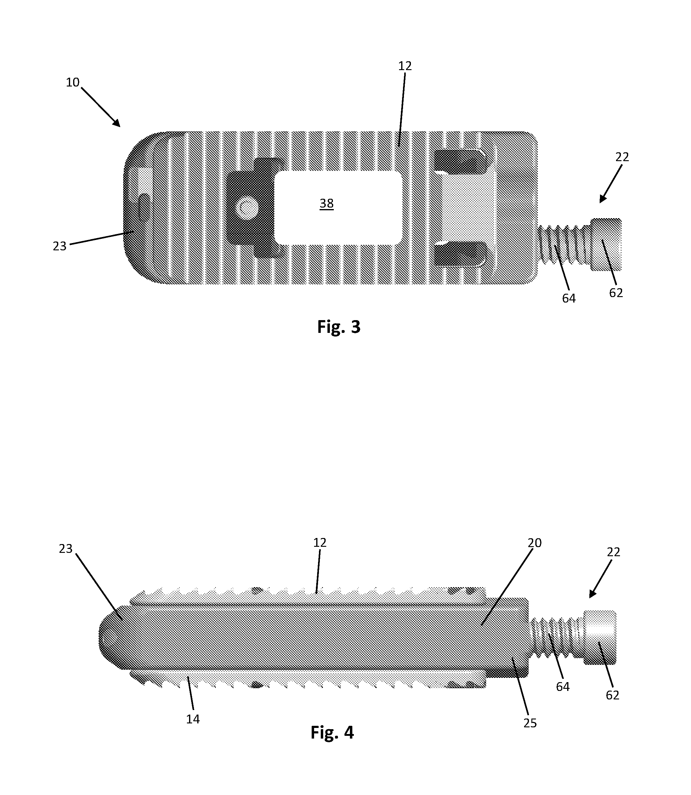
FIG. 3 is a top view of the expandable spinal fusion implant of FIG. 1;
FIG. 4 is a side view of the expandable spinal fusion implant of FIG. 1 in its collapsed state;
FIG. 5 is a leading end view of the expandable spinal fusion implant of FIG. 1 in its collapsed state;
FIG. 6 is a trailing end view of the expandable spinal fusion implant of FIG. 1 in its collapsed state;
FIG. 7 is an exploded view of the expandable spinal fusion implant;
FIG. 8 is a cross sectional view of the leading end of expandable spinal fusion implant in its expanded state:
FIG. 9 is a cross sectional view of the trailing end of the expandable spinal fusion implant in its collapsed state;
FIG. 10 is a cross sectional view of the expandable spinal fusion implant;
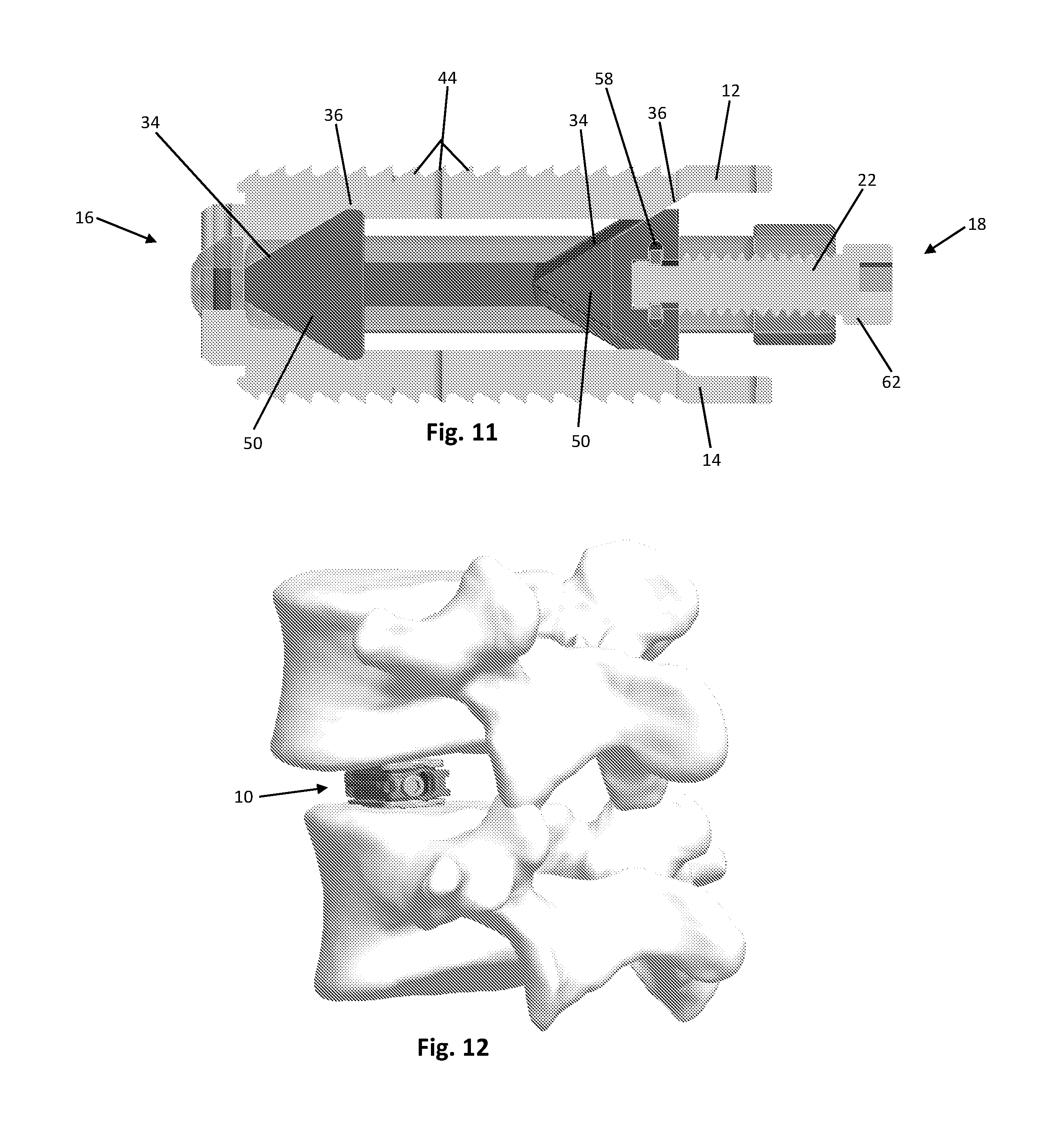
FIG. 11 is a cross sectional view of the expandable spinal fusion implant;
FIG. 12 is a perspective view of the expandable spinal fusion implant after insertion into the disc space; and
FIG. 13 is a perspective view of the expandable spinal fusion implant in its fully expanded state in the disc space.
DETAILED DESCRIPTION
FIGS. 1-13 illustrate an expandable spinal fusion implant for use during spinal surgery for implantation to an intervertebral disc space. According to an exemplary embodiment, the device is dimensioned for posterior approach surgery, e.g. posterior lumber interbody fusion (PLIF) and transforaminal lumbar interbody fusion (TLIF) approaches. However, according to an alternative embodiment, the device may also be dimensioned for use in a lateral approach to the anterior column of the spine. To reduce the risk of neural injury, the expandable spinal fusion implant has the ability to be implanted in a collapsed state (see FIG. 1) and expand to a height determined by the user (see FIG. 2). Expansion is accomplished by translating a wedge shaped expansion mechanism that is mated to the inferior and superior endplates 14, 12. As the expansion mechanism 26 is advanced towards the distal or leading end 16 of the implant 10 the endplates expand in height. To reduce the height of the implant or return the endplates back to their start position the expansion mechanism is advanced towards the proximal end of the device. In addition a large cannula at the trailing or proximal end of the device allows for post packing of bone graft material, i.e. filling the interior of the device with bone graft after the device has been inserted into the intervertebral space and expanded to the desired height. The ability to post pack improves the chances of a successful surgical outcome by allowing for insertion of a sufficient amount of bone graft in adequate contact with the vertebral body endplates adjacent the disc space to promote bone growth.
As shown in FIGS. 1-13, the expandable spinal fusion implant 10 has a top endplate 12 and a bottom endplate 14. The endplates 12, 14 have substantially identical features as will be further described. Each endplate has a bone contacting surface 46 and an interior surface 48. As shown in the exemplary embodiment, the bone contacting surfaces 46 may have anti-migration features 44. The interior surfaces 48 of the endplates 12, 14 have ramped portions 36 that correspond to the angles of the ramps 34, 35 on the expansion mechanism 26. The ramped portions 36 of the interior endplates also include a male dovetail feature 40 that mates with the female dovetail feature 38 on the ramps 34 of the expansion mechanism 26. Each endplate 12, 14 has a central fusion aperture 38 to allow for bone growth through the implant 10 and with the endplates of the adjacent vertebral bodies. In order for each endplate 12, 14 to expand it must remain stationary in the longitudinal axis as the expansion mechanism 26 translates both proximally and distally. Both endplates 12, 14 further include a distal extension 70 to aid in retaining the endplates within the housing 20. While the implant 10 according to an exemplary embodiment in FIGS. 1-13 is shown with flat endplates, endplates having built in lordosis, i.e. having a distal height extending from the bone contacting surface to the interior surface that is greater than the proximal height, are also contemplated.
The expandable spinal fusion implant 10 includes an expansion mechanism 26 located between the top and bottom endplates 12, 14. The expansion mechanism has two wedge portions 50, each of which as a superior ramp 34 and an inferior ramp 35 that correspond to and mate with the ramped portions 36, 37 of the superior and inferior endplates, respectively. Each endplate 12, 14 mates to the expansion mechanism 26 by an undercut or dovetail connection, at both the proximal end and the distal end, that allows movement between the wedge 50 and the endplate 12, 14. Each of the superior ramps 34 and inferior ramps 35 include a female dovetail feature 38 that mates with the male dovetail features 36 on the endplates 12, 14. An endplate safety retainer is housed within the expansion mechanism to prohibit removal of the endplates once assembled. The expansion mechanism 26 has a recess 56 at its proximal end dimensioned to receive the drive mechanism retainer 24 therein. The expansion mechanism 26 has a hollow interior defining a central fusion aperture 39 that aligns with the central fusion aperture 38 of the top and bottom endplates 12, 14 to allow for bone growth therethrough. The distal wedge 50 of the expansion mechanism 26 includes an endplate safety retainer 32 extending therethrough to prevent the dislocation of the endplates 12, 14 from the expansion mechanism 26.
As best shown in FIG. 7, the expandable spinal fusion implant 10 also includes a housing 20 dimensioned to house the expansion mechanism 26. The expansion mechanism 26 is supported in the housing 20 by two support rails 60. The housing 20 is defined by opposing lateral walls 21, a distal wall 23 and a proximal wall 25. The housing 20 has a longitudinal length that exceeds the longitudinal length of the endplates 12, 14. The distal wall 23 of the housing is tapered to aid in insertion of the implant 10. The distal wall 23 also includes recesses 58 for receiving the distal extensions 50 of the endplates 12, 14 to retain the endplates with in the housing 20. As seen in FIG. 6, the proximal wall 25 of the housing 20 includes a cannula 52 for receiving bone graft material into the central fusion aperture 39 of the expansion mechanism 26 as well as a threaded drive mechanism aperture 54 for receiving the drive mechanism 22 therethrough.
According to the exemplary embodiment, the drive mechanism 22 has a head 62 at its proximal end for engaging an actuator tool (not shown) and a threaded shaft 64 extending from the head 62 and terminating at the distal end with a drive mechanism retainer 24 configured to anchor the drive mechanism 22 to the expansion mechanism 26. The purpose of the drive mechanism 22 is to translate the expansion mechanism 26 both proximally and distally. The threaded shaft 64 of the drive mechanism 22 engages with the threaded aperture 54 of the housing 20 at the proximal end 25 and also mates with the recess 56 at the proximal end of the expansion mechanism 26 and is retained with the expansion mechanism 26 by a drive mechanism retainer 24. As best seen in FIG. 6, the drive mechanism 22 is located at a position within the implant 10 that is offset from the central longitudinal axis of the implant 10 to allow for post packing of bone graft through the cannula 52 and into the central fusion aperture 39.
According to the exemplary embodiment, the expandable spinal fusion implant 10 is implanted into a patient by first accessing the desired intervertebral disc space via lateral approach to the anterior spinal column or a posterior (e.g. PLIF or TLIF) approach. The implant 10 is inserted in its collapsed state into the intervertebral disc space and maneuvered into a desired position. Once the desired position is reached, a tool is engaged with the drive mechanism 22 to turn the drive mechanism 22 and thereby urge the expansion mechanism 26 in the distal direction and consequently increase the distance between the top and bottom endplates 12, 14. The drive mechanism 22 can then be turned in the opposite direction to urge the expansion mechanism 26 in the proximal direction in order to decrease the distance between the endplates 12, 14 if necessary. Once the implant 10 has been set at the desired height, bone graft can be introduced through the cannula 52 in the proximal end 25 of the housing 20 to the interior of the implant 10, into the central fusion apertures 38, 39 of the expansion mechanism 26 and endplates 12, 14.
* * * * *
D00000
D00001
D00002
D00003
D00004
D00005
D00006
D00007
XML
uspto.report is an independent third-party trademark research tool that is not affiliated, endorsed, or sponsored by the United States Patent and Trademark Office (USPTO) or any other governmental organization. The information provided by uspto.report is based on publicly available data at the time of writing and is intended for informational purposes only.
While we strive to provide accurate and up-to-date information, we do not guarantee the accuracy, completeness, reliability, or suitability of the information displayed on this site. The use of this site is at your own risk. Any reliance you place on such information is therefore strictly at your own risk.
All official trademark data, including owner information, should be verified by visiting the official USPTO website at www.uspto.gov. This site is not intended to replace professional legal advice and should not be used as a substitute for consulting with a legal professional who is knowledgeable about trademark law.