Hybrid rear cover and mounting bracket for electronic display
Dunn , et al. Feb
U.S. patent number 10,212,845 [Application Number 15/494,614] was granted by the patent office on 2019-02-19 for hybrid rear cover and mounting bracket for electronic display. This patent grant is currently assigned to Manufacturing Resources International, Inc.. The grantee listed for this patent is Manufacturing Resources International, Inc.. Invention is credited to Kyle Azevedo, Marcos Diaz, William Dunn.

| United States Patent | 10,212,845 |
| Dunn , et al. | February 19, 2019 |
| **Please see images for: ( Certificate of Correction ) ** |
Hybrid rear cover and mounting bracket for electronic display
Abstract
A system and method for mounting an electronic display is disclosed herein. A rear cover mounting bracket may contain a rear plate and a sidewall which surrounds a perimeter of the plate. A plurality of mounting holes may be placed within the plate to allow fastening the rear plate to a vertical surface. An electronic display assembly module may contain a thermal plate where the attachment of the rear cover mounting bracket to the module creates a plenum which can house one or more electronic components. In a preferred embodiment, the rear plate contains a pair of hooks and the module contains a pair of corresponding cylinders which can be engaged with the hooks so that the module can hang from the hooks.
| Inventors: | Dunn; William (Alpharetta, GA), Diaz; Marcos (Alpharetta, GA), Azevedo; Kyle (Alpharetta, GA) | ||||||||||
|---|---|---|---|---|---|---|---|---|---|---|---|
| Applicant: |
|
||||||||||
| Assignee: | Manufacturing Resources
International, Inc. (Alpharetta, GA) |
||||||||||
| Family ID: | 54070608 | ||||||||||
| Appl. No.: | 15/494,614 | ||||||||||
| Filed: | April 24, 2017 |
Prior Publication Data
| Document Identifier | Publication Date | |
|---|---|---|
| US 20170231112 A1 | Aug 10, 2017 | |
Related U.S. Patent Documents
| Application Number | Filing Date | Patent Number | Issue Date | ||
|---|---|---|---|---|---|
| 14645076 | Mar 11, 2015 | 9655289 | |||
| 61951344 | Mar 11, 2014 | ||||
| Current U.S. Class: | 1/1 |
| Current CPC Class: | H05K 5/0017 (20130101); G02F 1/133308 (20130101); F16M 13/02 (20130101); H05K 7/20972 (20130101); H05K 7/18 (20130101); G06F 1/1601 (20130101); H05K 7/2039 (20130101); F16M 11/22 (20130101); H04N 5/64 (20130101); H05K 7/20145 (20130101); G02F 1/133603 (20130101); Y10T 29/49826 (20150115); G02F 2001/133628 (20130101); G02F 2001/133314 (20130101) |
| Current International Class: | H05K 7/20 (20060101); G02F 1/133 (20060101); H04N 5/64 (20060101); G02F 1/1333 (20060101); H05K 5/00 (20060101); H05K 7/18 (20060101); G06F 1/16 (20060101); G02F 1/1335 (20060101) |
References Cited [Referenced By]
U.S. Patent Documents
| 2029221 | January 1936 | Burgess et al. |
| 2678860 | May 1954 | Peterson |
| 3984931 | October 1976 | Belokin, Jr. |
| 4093355 | June 1978 | Kaplit et al. |
| 4169327 | October 1979 | Stilling |
| 4267657 | May 1981 | Kloke |
| 4327513 | May 1982 | de Gunzburg |
| 4452000 | June 1984 | Gandy |
| 4547987 | October 1985 | Stilling |
| 4593978 | June 1986 | Mourey et al. |
| 4634225 | January 1987 | Haim et al. |
| 4748765 | June 1988 | Martin |
| 4759143 | July 1988 | Pomerleau |
| 4763993 | August 1988 | Vogeley et al. |
| 4817317 | April 1989 | Kovalak, Jr. |
| 4903423 | February 1990 | Hinca |
| 4905390 | March 1990 | Stilling |
| 4921041 | May 1990 | Akachi |
| 4952783 | August 1990 | Aufderheide et al. |
| 4952925 | August 1990 | Haastert |
| 5029982 | July 1991 | Nash |
| 5088806 | February 1992 | McCartney et al. |
| 5247374 | September 1993 | Terada |
| 5282114 | January 1994 | Stone |
| 5293930 | March 1994 | Pitasi |
| 5299109 | March 1994 | Grondal |
| 5423142 | June 1995 | Douglas et al. |
| 5432526 | July 1995 | Hyatt |
| 5457905 | October 1995 | Kaplan |
| 5493802 | February 1996 | Simson |
| 5535816 | July 1996 | Ishida |
| D373120 | August 1996 | Andre et al. |
| 5559614 | September 1996 | Urbish et al. |
| 5621614 | April 1997 | O'Neill |
| 5657641 | August 1997 | Cunningham et al. |
| 5717424 | February 1998 | Simson et al. |
| 5748269 | May 1998 | Harris et al. |
| 5755050 | May 1998 | Aiken |
| 5765743 | June 1998 | Sakiura et al. |
| 5767489 | June 1998 | Ferrier |
| 5803424 | September 1998 | Keehn et al. |
| 5808418 | September 1998 | Pitman et al. |
| 5818010 | October 1998 | McCann |
| 5818694 | October 1998 | Daikoku et al. |
| 5835179 | November 1998 | Yamanaka |
| 5864465 | January 1999 | Liu |
| 5869818 | February 1999 | Kim |
| 5869919 | February 1999 | Sato et al. |
| 5899027 | May 1999 | St. Louis |
| 5903433 | May 1999 | Gudmundsson |
| D415736 | October 1999 | Witte |
| 5991153 | November 1999 | Heady et al. |
| 6003015 | December 1999 | Kang et al. |
| 6007205 | December 1999 | Fujimori |
| 6050833 | April 2000 | Danzyger et al. |
| 6089751 | July 2000 | Conover et al. |
| 6104451 | August 2000 | Matsuoka et al. |
| 6157432 | December 2000 | Helbing |
| 6172869 | January 2001 | Hood, III et al. |
| 6181070 | January 2001 | Dunn et al. |
| 6191839 | February 2001 | Briley et al. |
| 6198222 | March 2001 | Chang |
| 6211934 | April 2001 | Habing et al. |
| 6215655 | April 2001 | Heady et al. |
| 6231446 | May 2001 | Majima et al. |
| 6351381 | February 2002 | Bilski et al. |
| 6392727 | May 2002 | Larson et al. |
| 6405463 | June 2002 | Roddy et al. |
| 6417900 | July 2002 | Shin et al. |
| 6428198 | August 2002 | Saccomanno et al. |
| 6469752 | October 2002 | Ishikawa et al. |
| 6473150 | October 2002 | Takushima et al. |
| D467561 | December 2002 | Kosciolek |
| 6493440 | December 2002 | Gromatsky et al. |
| 6494429 | December 2002 | Tajima |
| 6504713 | January 2003 | Pandolfi et al. |
| 6535266 | March 2003 | Nemeth et al. |
| 6557284 | May 2003 | Nolan |
| 6628355 | September 2003 | Takahara |
| 6714410 | March 2004 | Wellhofer |
| 6727468 | April 2004 | Nemeth |
| 6748685 | June 2004 | Peel |
| 6758002 | July 2004 | Duguay |
| 6825828 | November 2004 | Burke et al. |
| 6839104 | January 2005 | Taniguchi et al. |
| 6885412 | April 2005 | Ohnishi et al. |
| 6886942 | May 2005 | Okada et al. |
| 6891135 | May 2005 | Pala et al. |
| 6909486 | June 2005 | Wang et al. |
| 6943768 | September 2005 | Cavanaugh et al. |
| 6961108 | November 2005 | Wang et al. |
| 6962528 | November 2005 | Yokota |
| 6976330 | December 2005 | Milliken |
| 7015470 | March 2006 | Faytlin et al. |
| 7059757 | June 2006 | Shimizu |
| 7083285 | August 2006 | Hsu et al. |
| D530686 | October 2006 | Reza |
| 7157838 | January 2007 | Thielemans et al. |
| 7161803 | January 2007 | Heady |
| 7190587 | March 2007 | Kim et al. |
| 7209349 | April 2007 | Chien et al. |
| 7210839 | May 2007 | Jung et al. |
| 7212403 | May 2007 | Rockenfeller |
| D544848 | June 2007 | Marz et al. |
| 7226176 | June 2007 | Huang |
| 7269023 | September 2007 | Nagano |
| 7284874 | October 2007 | Jeong et al. |
| 7292435 | November 2007 | She |
| 7339782 | March 2008 | Landes et al. |
| 7452121 | November 2008 | Cho et al. |
| 7457113 | November 2008 | Kumhyr et al. |
| 7480140 | January 2009 | Hara et al. |
| 7513830 | April 2009 | Hajder et al. |
| 7535543 | May 2009 | Dewa et al. |
| D595678 | July 2009 | Dunn |
| 7589958 | September 2009 | Smith |
| 7601067 | October 2009 | Anderson |
| 7602469 | October 2009 | Shin |
| 7609506 | October 2009 | Aguirre |
| D608775 | January 2010 | Leung |
| 7667964 | February 2010 | Kang et al. |
| 7752858 | July 2010 | Johnson et al. |
| 7753567 | July 2010 | Kang et al. |
| 7768775 | August 2010 | Kim |
| 7800706 | September 2010 | Kim et al. |
| 7813124 | October 2010 | Karppanen |
| 7903416 | March 2011 | Chou |
| 7985139 | July 2011 | Lind et al. |
| 7995342 | August 2011 | Nakamichi et al. |
| 8004648 | August 2011 | Dunn |
| 8006435 | August 2011 | DeBlonk et al. |
| 8016452 | September 2011 | Dunn |
| 8035968 | October 2011 | Kwon et al. |
| 8081465 | December 2011 | Nishiura |
| 8102173 | January 2012 | Merrow |
| 8116081 | February 2012 | Crick, Jr. |
| 8142027 | March 2012 | Sakai |
| 8208115 | June 2012 | Dunn |
| 8223311 | July 2012 | Kim et al. |
| 8241573 | August 2012 | Banerjee et al. |
| 8248784 | August 2012 | Nakamichi et al. |
| 8254121 | August 2012 | Lee et al. |
| 8269916 | September 2012 | Ohkawa |
| 8270163 | September 2012 | Nakamichi et al. |
| 8274622 | September 2012 | Dunn |
| 8274789 | September 2012 | Nakamichi et al. |
| 8300203 | October 2012 | Nakamichi et al. |
| 8320119 | November 2012 | Isoshima et al. |
| 8351014 | January 2013 | Dunn |
| 8358397 | January 2013 | Dunn |
| 8369083 | February 2013 | Dunn et al. |
| 8373841 | February 2013 | Dunn |
| 8379182 | February 2013 | Dunn |
| 8400608 | March 2013 | Takahashi et al. |
| 8418387 | April 2013 | Swatt et al. |
| 8472174 | June 2013 | Idems et al. |
| 8472191 | June 2013 | Yamamoto et al. |
| 8482695 | July 2013 | Dunn |
| 8497972 | July 2013 | Dunn et al. |
| 8537302 | September 2013 | Dunn |
| 8649170 | February 2014 | Dunn et al. |
| 8649176 | February 2014 | Okada et al. |
| 8654302 | February 2014 | Dunn et al. |
| 8678603 | March 2014 | Zhang |
| 8693185 | April 2014 | Dunn et al. |
| 8700226 | April 2014 | Schuch et al. |
| 8711321 | April 2014 | Dunn et al. |
| 8749749 | June 2014 | Hubbard |
| 8755021 | June 2014 | Hubbard |
| 8760613 | June 2014 | Dunn |
| 8767165 | July 2014 | Dunn |
| 8773633 | July 2014 | Dunn et al. |
| 8804091 | August 2014 | Dunn et al. |
| 8823916 | September 2014 | Hubbard et al. |
| 8854572 | October 2014 | Dunn |
| 8854595 | October 2014 | Dunn |
| 8879042 | November 2014 | Dunn |
| 8988647 | March 2015 | Hubbard |
| 9030641 | May 2015 | Dunn |
| 9089079 | July 2015 | Dunn |
| 9119325 | August 2015 | Dunn et al. |
| 9119330 | August 2015 | Hubbard et al. |
| 9173322 | October 2015 | Dunn |
| 9173325 | October 2015 | Dunn |
| 9282676 | March 2016 | Diaz |
| 9456525 | September 2016 | Yoon et al. |
| 2001/0001459 | May 2001 | Savant et al. |
| 2001/0019454 | September 2001 | Tadic-Galeb et al. |
| 2001/0043290 | November 2001 | Yamamoto |
| 2001/0043293 | November 2001 | Inoue |
| 2002/0033919 | March 2002 | Sanelle et al. |
| 2002/0101553 | August 2002 | Enomoto et al. |
| 2002/0126248 | September 2002 | Yoshia |
| 2002/0148600 | October 2002 | Bosch et al. |
| 2002/0149714 | October 2002 | Anderson et al. |
| 2002/0154255 | October 2002 | Gromatzky et al. |
| 2002/0164944 | November 2002 | Haglid |
| 2002/0167637 | November 2002 | Burke et al. |
| 2003/0007109 | January 2003 | Park |
| 2003/0020884 | January 2003 | Okada et al. |
| 2003/0039094 | February 2003 | Sarkinen et al. |
| 2003/0104210 | June 2003 | Azumi et al. |
| 2003/0128511 | July 2003 | Nagashima et al. |
| 2003/0214785 | November 2003 | Perazzo |
| 2004/0012722 | January 2004 | Alvarez |
| 2004/0025389 | February 2004 | Peterson |
| 2004/0035558 | February 2004 | Todd et al. |
| 2004/0036834 | February 2004 | Ohnishi et al. |
| 2004/0103570 | June 2004 | Ruttenberg |
| 2004/0105159 | June 2004 | Saccomanno et al. |
| 2004/0165139 | August 2004 | Anderson et al. |
| 2004/0212548 | October 2004 | Ruttenberg |
| 2004/0223299 | November 2004 | Ghosh |
| 2004/0257492 | December 2004 | Mai et al. |
| 2005/0012039 | January 2005 | Faytlin et al. |
| 2005/0012722 | January 2005 | Chon |
| 2005/0062373 | March 2005 | Kim et al. |
| 2005/0073632 | April 2005 | Dunn et al. |
| 2005/0073639 | April 2005 | Pan |
| 2005/0105178 | May 2005 | Kim |
| 2005/0127796 | June 2005 | Olesen et al. |
| 2005/0134525 | June 2005 | Tanghe et al. |
| 2005/0134526 | June 2005 | Willem et al. |
| 2005/0213950 | September 2005 | Yoshimura |
| 2005/0229630 | October 2005 | Richter et al. |
| 2005/0237714 | October 2005 | Ebermann |
| 2005/0276053 | December 2005 | Nortrup et al. |
| 2005/0286131 | December 2005 | Saxena et al. |
| 2006/0012958 | January 2006 | Tomioka et al. |
| 2006/0012985 | January 2006 | Archie, Jr. et al. |
| 2006/0018093 | January 2006 | Lai et al. |
| 2006/0034051 | February 2006 | Wang et al. |
| 2006/0056994 | March 2006 | Van Lear et al. |
| 2006/0077636 | April 2006 | Kim |
| 2006/0082271 | April 2006 | Lee et al. |
| 2006/0092348 | May 2006 | Park |
| 2006/0125998 | June 2006 | Dewa et al. |
| 2006/0132699 | June 2006 | Cho |
| 2006/0137294 | June 2006 | Waits et al. |
| 2006/0177587 | August 2006 | Ishizuka et al. |
| 2006/0199514 | September 2006 | Kimura |
| 2006/0209266 | September 2006 | Utsunomiya |
| 2006/0215421 | September 2006 | Chang et al. |
| 2006/0218828 | October 2006 | Schrimpf et al. |
| 2006/0260790 | November 2006 | Theno et al. |
| 2006/0262079 | November 2006 | Seong et al. |
| 2006/0266499 | November 2006 | Choi et al. |
| 2006/0283579 | December 2006 | Ghosh et al. |
| 2007/0019419 | January 2007 | Hafuka et al. |
| 2007/0021217 | January 2007 | Wu |
| 2007/0030879 | February 2007 | Hatta |
| 2007/0047239 | March 2007 | Kang et al. |
| 2007/0065091 | March 2007 | Hinata et al. |
| 2007/0070615 | March 2007 | Joslin et al. |
| 2007/0076431 | April 2007 | Atarashi et al. |
| 2007/0103863 | May 2007 | Kim |
| 2007/0103866 | May 2007 | Park |
| 2007/0115686 | May 2007 | Tyberghien |
| 2007/0139574 | June 2007 | Ko et al. |
| 2007/0139929 | June 2007 | Yoo et al. |
| 2007/0140671 | June 2007 | Yoshimura |
| 2007/0151274 | July 2007 | Roche et al. |
| 2007/0151664 | July 2007 | Shin |
| 2007/0171353 | July 2007 | Hong |
| 2007/0206158 | September 2007 | Kinoshita et al. |
| 2007/0211205 | September 2007 | Shibata |
| 2007/0212211 | September 2007 | Chiyoda et al. |
| 2007/0217221 | September 2007 | Lee et al. |
| 2007/0237636 | October 2007 | Hsu |
| 2007/0253205 | November 2007 | Welker |
| 2007/0267174 | November 2007 | Kim |
| 2007/0276507 | November 2007 | Bertram et al. |
| 2008/0002350 | January 2008 | Farrugia |
| 2008/0055534 | March 2008 | Kawano |
| 2008/0076342 | March 2008 | Bryant et al. |
| 2008/0099193 | May 2008 | Aksamit et al. |
| 2008/0100186 | May 2008 | Li |
| 2008/0148609 | June 2008 | Ogoreve |
| 2008/0209934 | September 2008 | Richards |
| 2008/0218446 | September 2008 | Yamanaka |
| 2008/0236005 | October 2008 | Isayev et al. |
| 2008/0255901 | October 2008 | Carroll et al. |
| 2008/0267790 | October 2008 | Gaudet et al. |
| 2008/0283234 | November 2008 | Sagi et al. |
| 2008/0285290 | November 2008 | Ohashi et al. |
| 2008/0304219 | December 2008 | Chen |
| 2009/0009041 | January 2009 | Leidler |
| 2009/0009047 | January 2009 | Yanagawa |
| 2009/0009729 | January 2009 | Sakai |
| 2009/0016004 | January 2009 | McCoy |
| 2009/0086430 | April 2009 | Kang et al. |
| 2009/0104989 | April 2009 | Williams et al. |
| 2009/0120629 | May 2009 | Ashe |
| 2009/0122218 | May 2009 | Oh |
| 2009/0126906 | May 2009 | Dunn |
| 2009/0126907 | May 2009 | Dunn |
| 2009/0126914 | May 2009 | Dunn |
| 2009/0135365 | May 2009 | Dunn |
| 2009/0141199 | June 2009 | Fujikawa |
| 2009/0147170 | June 2009 | Oh et al. |
| 2009/0154096 | June 2009 | Iyengar et al. |
| 2009/0174626 | July 2009 | Isoshima et al. |
| 2009/0231807 | September 2009 | Bouissiere |
| 2009/0241388 | October 2009 | Dunn |
| 2009/0244472 | October 2009 | Dunn |
| 2009/0278007 | November 2009 | Taylor |
| 2009/0279240 | November 2009 | Karppanen |
| 2009/0302727 | December 2009 | Vincent et al. |
| 2009/0306820 | December 2009 | Simmons et al. |
| 2010/0060861 | March 2010 | Medin |
| 2010/0079949 | April 2010 | Nakamichi et al. |
| 2010/0162747 | July 2010 | Hamel et al. |
| 2010/0171889 | July 2010 | Pantel et al. |
| 2010/0182562 | July 2010 | Yoshida et al. |
| 2010/0220249 | September 2010 | Nakamichi |
| 2010/0226091 | September 2010 | Dunn |
| 2010/0232107 | September 2010 | Dunn |
| 2010/0238394 | September 2010 | Dunn |
| 2010/0321887 | December 2010 | Kwon et al. |
| 2011/0001898 | January 2011 | Mikubo et al. |
| 2011/0013114 | January 2011 | Dunn et al. |
| 2011/0019348 | January 2011 | Kludt et al. |
| 2011/0019363 | January 2011 | Vahlsing et al. |
| 2011/0051071 | March 2011 | Nakamichi et al. |
| 2011/0058326 | March 2011 | Idems et al. |
| 2011/0075361 | March 2011 | Nakamichi et al. |
| 2011/0083460 | April 2011 | Thomas et al. |
| 2011/0083824 | April 2011 | Rogers |
| 2011/0085301 | April 2011 | Dunn |
| 2011/0114384 | May 2011 | Sakamoto et al. |
| 2011/0116000 | May 2011 | Dunn et al. |
| 2011/0116231 | May 2011 | Dunn |
| 2011/0122162 | May 2011 | Sato |
| 2011/0134356 | June 2011 | Swatt et al. |
| 2011/0141672 | June 2011 | Farley, Jr. et al. |
| 2011/0141724 | June 2011 | Erion |
| 2011/0227467 | September 2011 | Foppe, Jr. et al. |
| 2011/0261523 | October 2011 | Dunn et al. |
| 2012/0006523 | January 2012 | Masahiro et al. |
| 2012/0012295 | January 2012 | Kakiuchi et al. |
| 2012/0012300 | January 2012 | Dunn et al. |
| 2012/0014063 | January 2012 | Weiss |
| 2012/0020114 | January 2012 | Miyamoto et al. |
| 2012/0038849 | February 2012 | Dunn et al. |
| 2012/0044217 | February 2012 | Okada et al. |
| 2012/0050958 | March 2012 | Sanford et al. |
| 2012/0106081 | May 2012 | Hubbard et al. |
| 2012/0206687 | August 2012 | Dunn et al. |
| 2012/0249402 | October 2012 | Kang |
| 2012/0255704 | October 2012 | Nakamichi |
| 2012/0274876 | November 2012 | Cappaert et al. |
| 2012/0284547 | November 2012 | Culbert et al. |
| 2013/0170140 | July 2013 | Dunn |
| 2013/0201685 | August 2013 | Messmore et al. |
| 2013/0211583 | August 2013 | Borra |
| 2013/0258659 | October 2013 | Erion |
| 2013/0270975 | October 2013 | Dunn et al. |
| 2013/0294039 | November 2013 | Chao |
| 2014/0044147 | February 2014 | Wyatt et al. |
| 2014/0085564 | March 2014 | Hendren et al. |
| 2014/0111758 | April 2014 | Dunn et al. |
| 2014/0113540 | April 2014 | Dunn et al. |
| 2014/0208626 | July 2014 | Moon |
| 2014/0313698 | October 2014 | Dunn et al. |
| 2014/0314395 | October 2014 | Dunn et al. |
| 2011248190 | May 2011 | AU | |||
| 2702363 | May 2005 | CN | |||
| 1408476 | Apr 2004 | EP | |||
| 1647766 | Apr 2006 | EP | |||
| 1762892 | Mar 2007 | EP | |||
| 1951020 | Jul 2008 | EP | |||
| 2225603 | Sep 2010 | EP | |||
| 2370987 | Oct 2011 | EP | |||
| 2603831 | Jun 2013 | EP | |||
| 153110 | Nov 1920 | GB | |||
| 2402205 | Dec 2004 | GB | |||
| 402062015 | Mar 1990 | JP | |||
| 402307080 | Dec 1990 | JP | |||
| 3153212 | Jul 1991 | JP | |||
| 6082745 | Mar 1994 | JP | |||
| 8115788 | May 1996 | JP | |||
| 8194437 | Jul 1996 | JP | |||
| 8339034 | Dec 1996 | JP | |||
| H09246766 | Sep 1997 | JP | |||
| 11160727 | Jun 1999 | JP | |||
| H11296094 | Oct 1999 | JP | |||
| 2001209126 | Aug 2001 | JP | |||
| 2002158475 | May 2002 | JP | |||
| 2004053749 | Feb 2004 | JP | |||
| 2005017556 | Jan 2005 | JP | |||
| 2000131682 | May 2005 | JP | |||
| 2005134849 | May 2005 | JP | |||
| 2005265922 | Sep 2005 | JP | |||
| 2005292939 | Oct 2005 | JP | |||
| 2005332253 | Dec 2005 | JP | |||
| 2006513577 | Apr 2006 | JP | |||
| 2007322718 | May 2006 | JP | |||
| 2006148047 | Jun 2006 | JP | |||
| 2006163217 | Jun 2006 | JP | |||
| 2006198344 | Aug 2006 | JP | |||
| 2007003638 | Jan 2007 | JP | |||
| 09307257 | Nov 2007 | JP | |||
| 2008010361 | Jan 2008 | JP | |||
| 2008292743 | Dec 2008 | JP | |||
| 2010024624 | Feb 2010 | JP | |||
| 200163508 | Jul 2000 | KR | |||
| 200206768 | Dec 2000 | KR | |||
| 200236278 | Oct 2001 | KR | |||
| 2002-0057425 | Jul 2002 | KR | |||
| 200286961 | Aug 2002 | KR | |||
| 200366674 | Nov 2004 | KR | |||
| 20050033986 | Apr 2005 | KR | |||
| 200401354 | Nov 2005 | KR | |||
| 20060016469 | Feb 2006 | KR | |||
| 100666961 | Jan 2007 | KR | |||
| 1020070070675 | Apr 2007 | KR | |||
| 1020070048294 | Aug 2007 | KR | |||
| 2513043 | Apr 2014 | RU | |||
| WO2005079129 | Aug 2005 | WO | |||
| WO2008050660 | May 2008 | WO | |||
| WO2009065125 | May 2009 | WO | |||
| WO2009065125 | May 2009 | WO | |||
| WO2009135308 | Nov 2009 | WO | |||
| WO2010007821 | Feb 2010 | WO | |||
| WO2010080624 | Jul 2010 | WO | |||
| WO2011059793 | May 2011 | WO | |||
| 2011069084 | Jun 2011 | WO | |||
| WO2011072217 | Jun 2011 | WO | |||
| WO2011140179 | Nov 2011 | WO | |||
| WO2011150078 | Dec 2011 | WO | |||
| WO2012006620 | Jan 2012 | WO | |||
| WO2012021573 | Feb 2012 | WO | |||
| WO2012024426 | Feb 2012 | WO | |||
Other References
|
Itsenclosures, Product Catalog, 2009, 48 pages. cited by applicant . Itsenclosures, Standard Product Data Sheet, 2011, 18 pages. cited by applicant . Sunbritetv, All Weather Outdoor LCD Television Model 4610HD, 2008, 1 page. cited by applicant . Sunbritetv, Introduces Two New All-Weather Outdoor Televisions InfoComm 2008, 7 pages. cited by applicant . Itsenclosures, Viewstation, 2017, 16 pages. cited by applicant . Novitsky, Driving LEDs versus CCFLs for LCD backlighting, Nov. 12, 2007, 6 pages. cited by applicant . Federman, Cooling Flat Panel Displays, 2011, 4 pages. cited by applicant . Zeeff, T.M., EMC analysis of an 18'' LCD monitor, 2000, 1 page. cited by applicant . I-Tech Company, 65'' Outdoor Digital Signage Sunlight All Weather Proof LCD, 1 Page. cited by applicant . sunlightlcd.com, 46'' All Weather NEMA4 Outdoor High Brightness (Model: GS4600L), Mar. 11, 2009, 2 Pages. cited by applicant . Wankhede, Evaluation of Cooling Solutions for Outdoor Electronics, Sep. 17-19, 2007, 6 pages. cited by applicant . Bureau of Ships Navy Department, Guide Manual of Cooling methods for Electronic Equipment, Mar. 31, 1955, 212 pages. cited by applicant . Scott, Cooling of Electronic Equipment, Apr. 4, 1947, 119 pages. cited by applicant . Sergent, Thermal Management Handbook for Electronic Assemblies, Aug. 14, 1998, 190 pages. cited by applicant . Steinberg, Cooling Techniques for Electronic Equipment First Edition, 1980, 255 pages. cited by applicant . Steinberg, Cooling Techniques for Electronic Equipment Second Edition, 1991, 299 pages. cited by applicant . Yeh, Thermal Management of Microelectronic Equipment, Oct. 15, 2002, 148 pages. cited by applicant. |
Primary Examiner: Dravininkas; Adam B
Attorney, Agent or Firm: Standley Law Group LLP
Parent Case Text
CROSS-REFERENCE TO RELATED APPLICATIONS
This application is a continuation of U.S. patent application Ser. No. 14/645,076 filed on Mar. 11, 2015, which claims priority to U.S. Provisional Application No. 61/951,344 filed on Mar. 11, 2014. Both aforementioned applications are incorporated by reference as if fully recited herein.
Claims
We claim:
1. A system for mounting an electronic display comprising: a rear cover mounting bracket having a rear plate; an electronic display assembly module having a thermal plate where the electronic display assembly module attaches to the rear cover mounting bracket to define a gaseously sealed enclosed chamber between the thermal plate and the rear plate, wherein said enclosed chamber is located entirely behind the electronic display assembly; an electrical component placed within the enclosed chamber; wherein the electronic display assembly module is removably connected to the rear cover mounting bracket; a first partition within the enclosed chamber; and a circulating fan positioned within the enclosed chamber for circulating gas within the enclosed chamber.
2. The system of claim 1 further comprising: a plurality of mounting holes placed within the rear plate; the mounting holes are placed outside of the enclosed chamber; and wherein the rear cover mounting bracket has a sidewall which surrounds a perimeter of the plate.
3. The system of claim 2 wherein: the circulating fan is positioned on the first partition; and the circulating gas is air.
4. The system of claim 1 wherein: the rear plate is adapted to fit against a vertical surface.
5. The system of claim 1 further comprising: a channel defined by the space between an electronic display and the thermal plate; and a fan positioned to draw external air through the channel but not through the enclosed chamber.
6. The system of claim 1 further wherein the bottom side of the electronic display assembly module is adapted to rotate outwardly away from the rear cover mounting bracket when the electronic display assembly module is attached to the rear cover mounting bracket.
7. The system of claim 1 further comprising: a pair of hooks attached to the rear plate; and a pair of round posts attached to the electronic display assembly module which fit within the hooks and allow the electronic display assembly module to hang from the hooks.
8. The system of claim 1 wherein the electrical component is a power module.
9. The system of claim 1, further comprising: a second partition within the enclosed chamber that is oriented substantially perpendicular to the first partition; wherein the circulating fan is positioned on either the first or the second partition for circulating gas around the enclosed chamber; and wherein the gas within the enclosed chamber circulates in a loop pattern when the enclosed chamber is sealed.
10. A system for mounting an electronic display comprising: a rear cover mounting bracket having a rear plate; a pair of hooks attached to the rear plate; an electronic display assembly module containing an electronic display and having a pair of horizontal posts, each post being sized to fit within a hook so that the electronic display assembly module can hang from the hooks, the electronic display assembly module having a thermal plate wherein the electronic display assembly module attaches to the rear cover mounting bracket to define a plenum between the thermal plate and the rear plate; an electrical assembly placed within the plenum; a latch positioned near the bottom of the electronic display assembly module; wherein the electronic display assembly module is adapted to allow the bottom of the electronic display assembly module to rotate outwardly away from the rear cover mounting bracket when the electronic display assembly module is attached to the rear cover mounting bracket; a first partition within the plenum; a second partition within the plenum that is oriented substantially perpendicular to the first partition; a circulating fan positioned on either the first or the second partition for circulating gas around the plenum; and wherein the gas within the plenum circulates in a loop pattern when the plenum is sealed.
11. The system of claim 10 further comprising: a plurality of holes in the rear plate for attaching the rear plate to a wall.
12. The system of claim 10 further comprising: a pair of locating walls positioned on each post where the space between the locating walls defines an area of each post that is accepted by the hook.
13. The system of claim 10 further comprising: a channel within the electronic display assembly module that is defined by the space between the electronic display and a thermal plate; a fan positioned to force external air through the channel.
14. The system of claim 10 wherein the electrical assembly is a power module.
15. A method for mounting an electronic display comprising the steps of: attaching a rear cover mounting bracket to a vertical surface, said rear cover mounting bracket having a pair of hooks positioned near a top of the rear cover mounting bracket; presenting an electronic display assembly module having a thermal plate and a pair of horizontal rods near a top of the electronic display assembly module; engaging the horizontal rods with the hooks so that the electronic display assembly module can hang from the hooks; rotating a bottom portion of the electronic display assembly module outwardly away from the rear cover mounting bracket when the electronic display assembly module is attached to the rear cover mounting bracket; attaching a bottom portion of the rear cover mounting bracket to the bottom portion of the electronic display assembly module; creating an enclosed chamber between the rear cover mounting bracket and the thermal plate; placing an electrical assembly within the enclosed chamber; placing a first partition within the enclosed chamber; positioning a circulating fan in the enclosed chamber for circulating gas within the enclosed chamber; and circulating the gas in a loop pattern around the first partition when the enclosed chamber is sealed.
16. The method of claim 15 wherein: the entire weight of the electronic display assembly module is permitted to hang from the hooks once engaged with the horizontal rods.
17. The method of claim 15 wherein: the step of engaging the horizontal rods with the hooks comprises placing the hook on a portion of the rod which is defined by the space between a pair of locating walls.
18. The method of claim 15 wherein: the step of attaching the rear cover mounting bracket to the electronic display assembly module comprises engaging a first portion of a latch which is attached to the rear cover mounting bracket with a second portion of a latch which is attached to the electronic display assembly module.
19. The method of claim 15 wherein: the step of attaching the rear cover mounting bracket to the electronic display assembly creates the enclosed chamber which is sealed from the exterior air.
Description
TECHNICAL FIELD
Embodiments generally relate to systems and methods for installing and cooling electronic displays.
BACKGROUND OF THE ART
Electronic displays are sometimes used in outdoor environments or other areas where the surrounding temperatures may be high or there may be other sources of heat such as solar loading causing the temperatures within the display to rise. However, some portions of the display can be difficult to cool as simply ingesting ambient air into some portions of the display can introduce dust and contaminates into sensitive portions of the display, which can lead to premature failures. Further, it is now desirable to provide an improved system for installing large electronic displays in public areas.
SUMMARY OF THE EXEMPLARY EMBODIMENTS
A system and method for mounting an electronic display is disclosed herein. A rear cover mounting bracket may contain a rear plate and a sidewall which surrounds a perimeter of the plate. A plurality of mounting holes may be placed within the plate to allow fastening the rear plate to a vertical surface. An electronic display assembly module may contain a thermal plate where the attachment of the rear cover mounting bracket to the module creates a plenum which can house one or more electronic components. In a preferred embodiment, the rear plate contains a pair of hooks and the module contains a pair of corresponding cylinders which can be engaged with the hooks so that the module can hang from the hooks.
The foregoing and other features and advantages of the present invention will be apparent from the following more detailed description of the particular embodiments, as illustrated in the accompanying drawings.
BRIEF DESCRIPTION OF THE DRAWINGS
A better understanding of an exemplary embodiment will be obtained from a reading of the following detailed description and the accompanying drawings wherein identical reference characters refer to identical parts and in which:
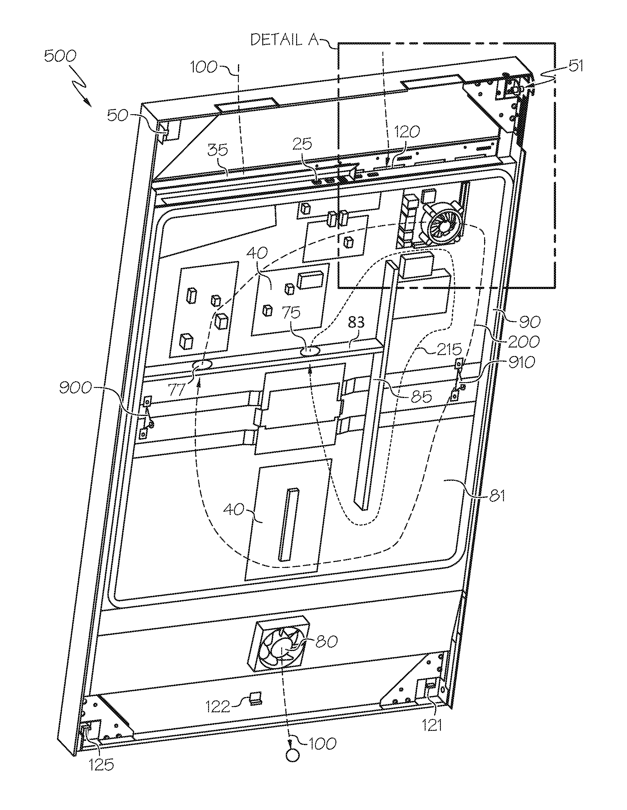
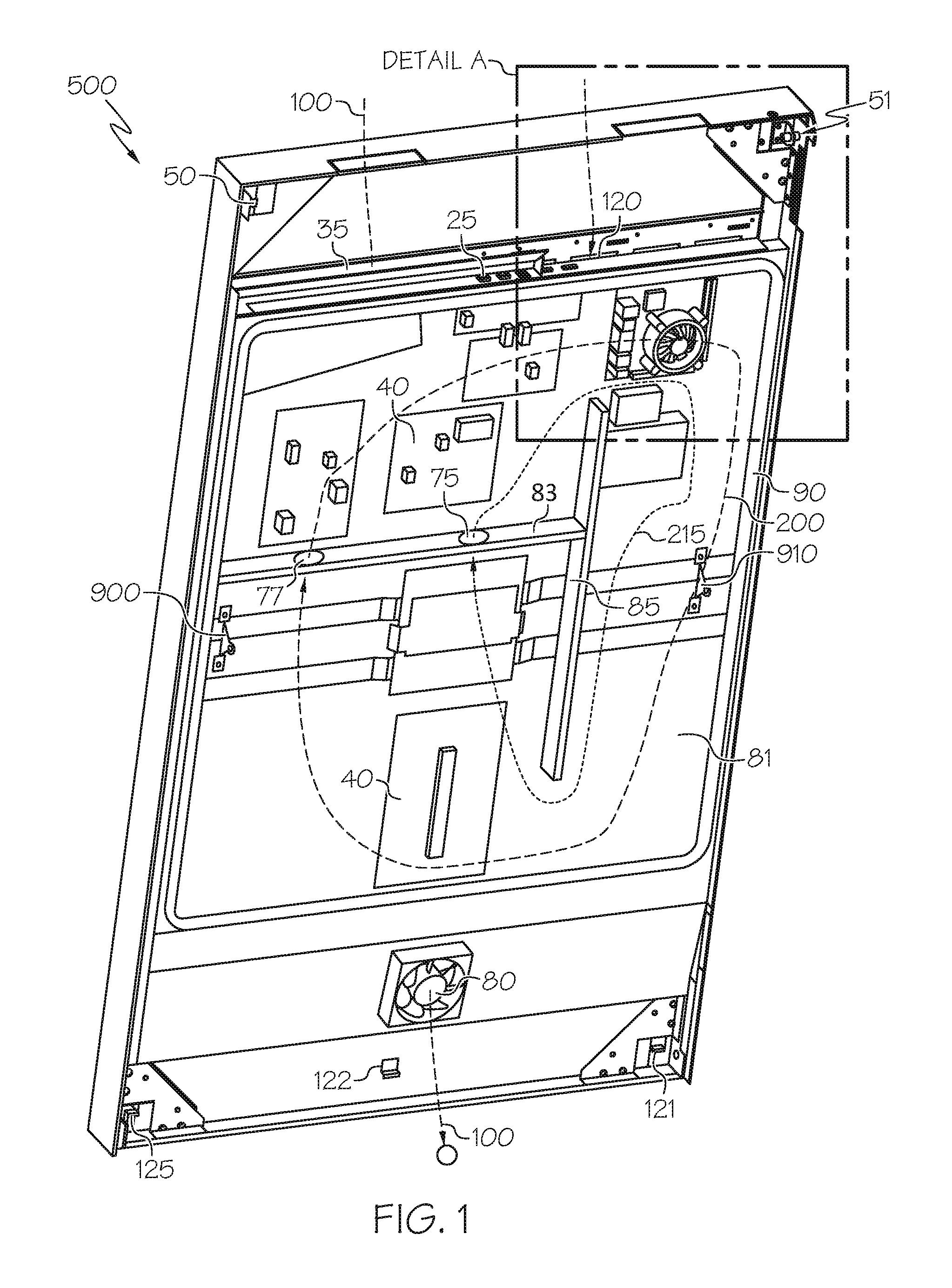
FIG. 1 is a rear perspective view of an exemplary electronic display assembly module showing Detail A.
FIG. 2 is a detailed rear perspective view of Detail A shown in FIG. 1.
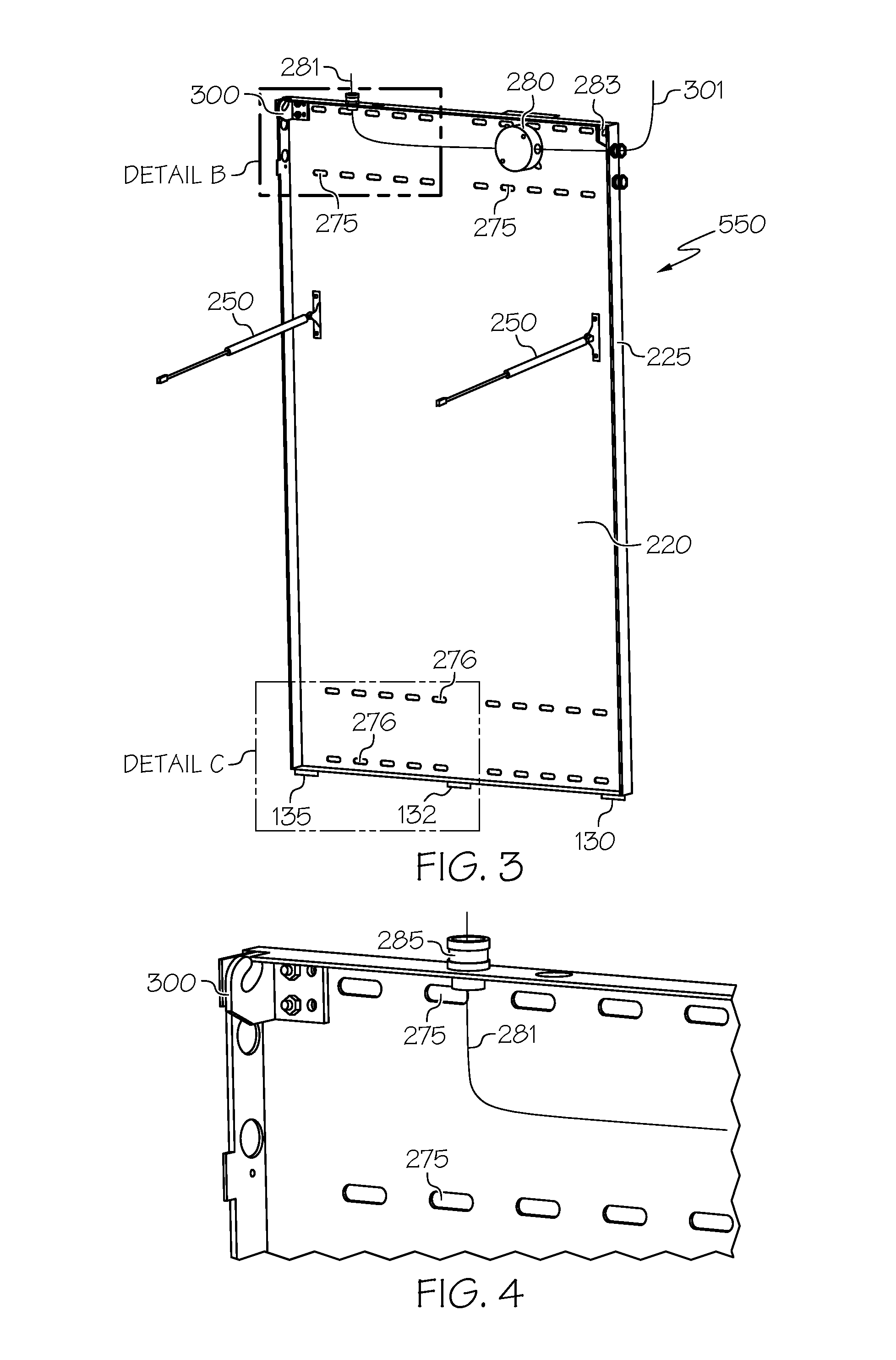
FIG. 3 is a front perspective view of an exemplary hybrid rear cover and mounting bracket, once fastened to a vertical surface and connected to service wiring.
FIG. 4 is a detailed front perspective view of Detail B shown in FIG. 3.
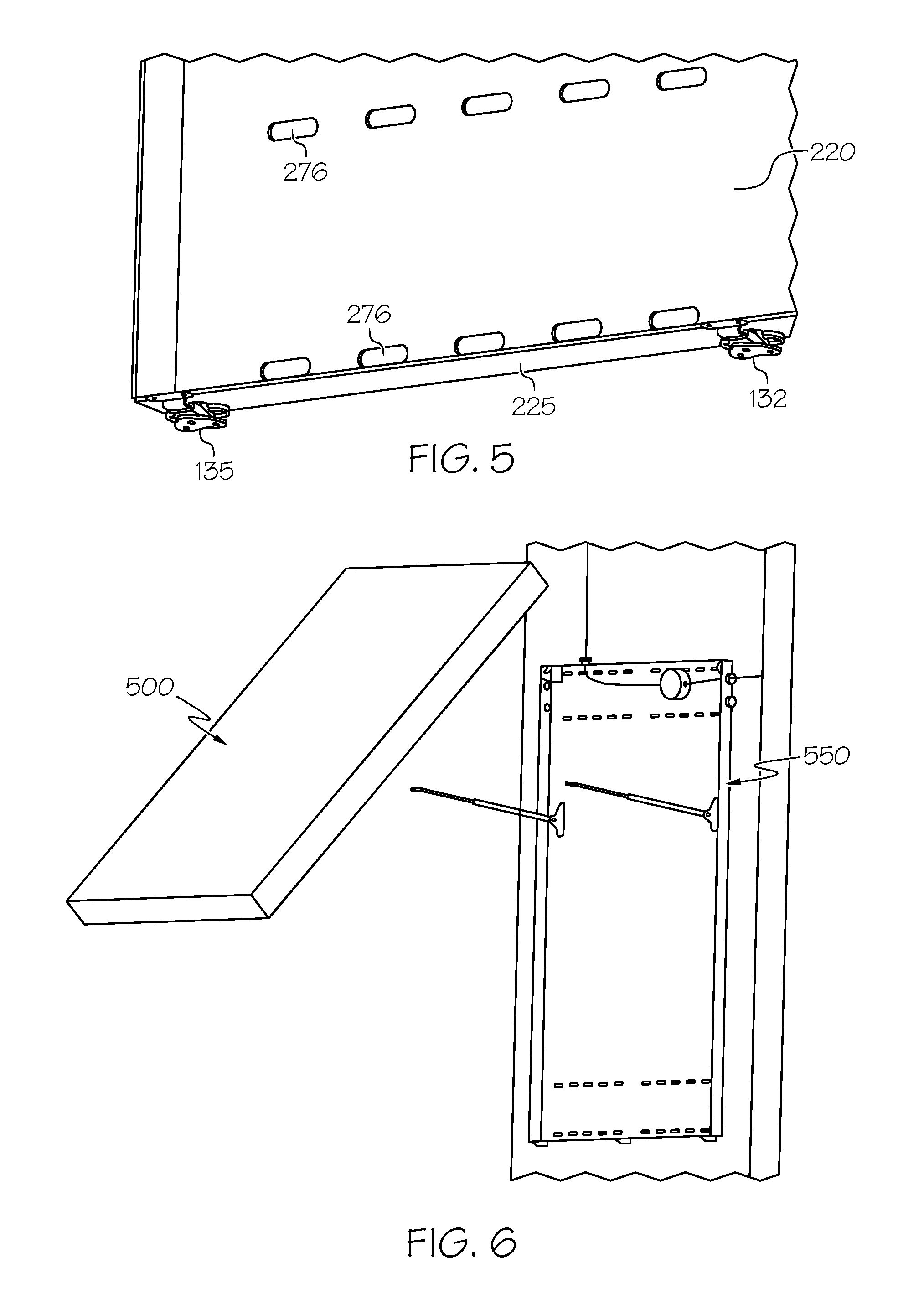
FIG. 5 is a detailed front perspective view of Detail C shown in FIG. 3.
FIG. 6 is a front perspective view of the exemplary method for attaching the electronic display assembly module to the hybrid rear cover and mounting bracket.
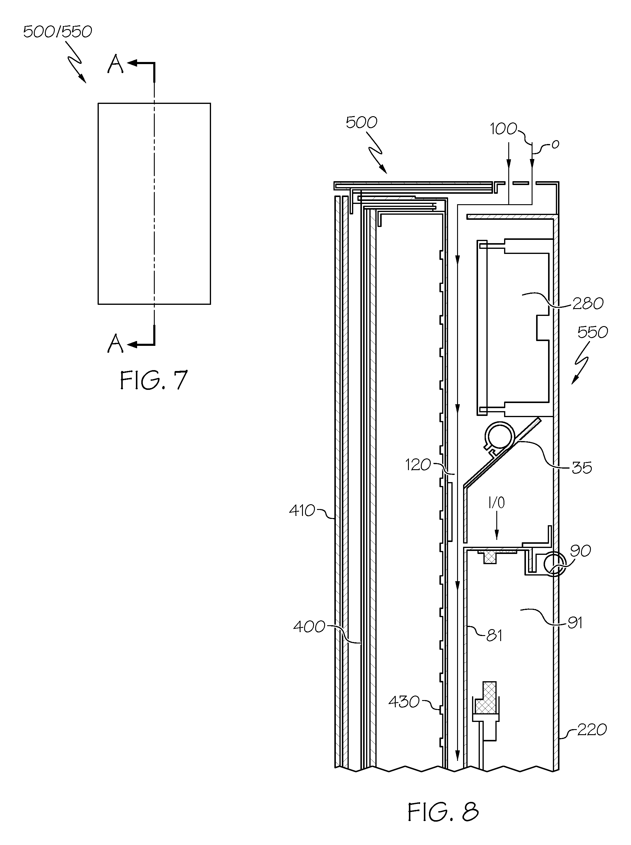
FIG. 7 is a front elevation view of the hybrid rear cover and mounting bracket once assembled with the electronic display assembly module and indicating the section line A-A.
FIG. 8 is a partial section view taken along the section line A-A and showing the top portion of the assembly.
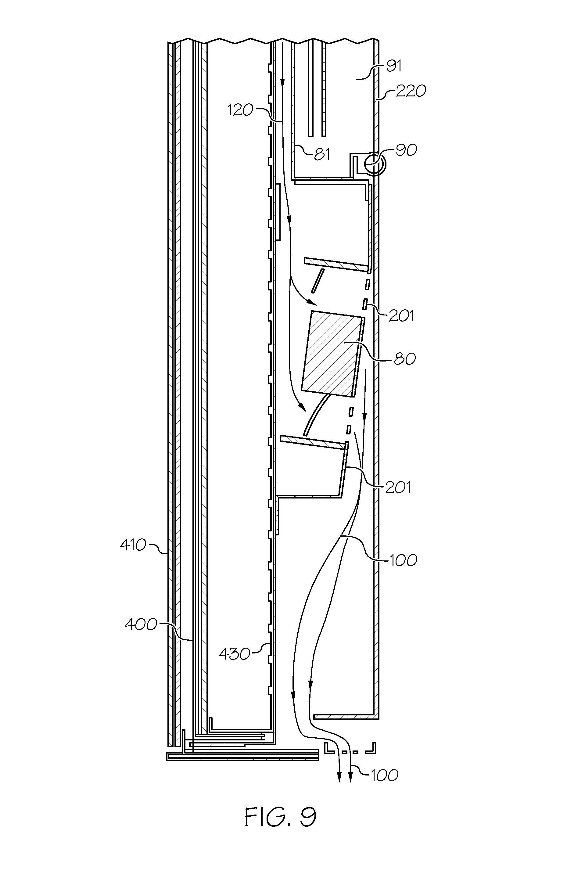
FIG. 9 is a partial section view taken along the section line A-A and showing the bottom portion of the assembly.
DETAILED DESCRIPTION
The invention is described more fully hereinafter with reference to the accompanying drawings, in which exemplary embodiments of the invention are shown. This invention may, however, be embodied in many different forms and should not be construed as limited to the exemplary embodiments set forth herein. Rather, these embodiments are provided so that this disclosure will be thorough and complete, and will fully convey the scope of the invention to those skilled in the art. In the drawings, the size and relative sizes of layers and regions may be exaggerated for clarity.
The terminology used herein is for the purpose of describing particular embodiments only and is not intended to be limiting of the invention. As used herein, the singular forms "a", "an" and "the" are intended to include the plural forms as well, unless the context clearly indicates otherwise. It will be further understood that the terms "comprises" and/or "comprising," when used in this specification, specify the presence of stated features, integers, steps, operations, elements, and/or components, but do not preclude the presence or addition of one or more other features, integers, steps, operations, elements, components, and/or groups thereof.
Embodiments of the invention are described herein with reference to illustrations that are schematic illustrations of idealized embodiments (and intermediate structures) of the invention. As such, variations from the shapes of the illustrations as a result, for example, of manufacturing techniques and/or tolerances, are to be expected. Thus, embodiments of the invention should not be construed as limited to the particular shapes of regions illustrated herein but are to include deviations in shapes that result, for example, from manufacturing.
Unless otherwise defined, all terms (including technical and scientific terms) used herein have the same meaning as commonly understood by one of ordinary skill in the art to which this invention belongs. It will be further understood that terms, such as those defined in commonly used dictionaries, should be interpreted as having a meaning that is consistent with their meaning in the context of the relevant art and will not be interpreted in an idealized or overly formal sense unless expressly so defined herein.
FIG. 1 is a rear perspective view of an exemplary electronic display assembly module 500 showing Detail A. A thermal mounting sheet 81 is placed behind the electronic display and contains a plurality of electrical assemblies 40 which may include but are not limited to: power supplies, video players, hard drives, microprocessors, printed circuit boards, and input/output electronics. A narrow channel 120 is preferably defined by the space between the thermal sheet 81 and the rear surface of the electronic display. External air 100 may be forced through the channel 120 by fan 80, which can then extract heat from both the rear surface of the electronic display as well as the thermal mounting sheet 81.
A gasket 90 is preferably attached to the thermal mounting sheet 81 and surrounds a portion of the perimeter of the thermal mounting sheet 81. When combined with the hybrid rear cover mounting bracket 550, the gasket 90 and sheet 81 define a gaseously-sealed plenum 91 which may contain the electrical assemblies 40. One or more fans 75/77 may cause the air within the plenum 91 to circulate around. Preferably, a pair of dividing walls 83/85 are used to define a loop around the plenum 91 which passes through only one of the dividing walls (here 83). In an exemplary embodiment, dividing wall 83 is perpendicular to dividing wall 85. Even more preferably, dividing wall 83 is arranged horizontally and contains the fan(s) while dividing wall 85 is connected to the end of dividing wall 83 but is arranged vertically and does not contain a fan. For exemplary airflow, it has been discovered that placing the first fan 75 near the center of the display assembly and the second fan 77 near the perimeter of the display assembly, causes a pair of circulating gas loops 215 and 200 respectfully. Preferably, the plenum 91 is sealed so that external air cannot enter the plenum 91 (and preferably prevents air, or any other gaseous matter with or without particulate, from exiting the plenum 91).
A plurality of input/output electrical connections 25 are preferably placed at the top of the module 500 and underneath a water guard 35. Also, a pair of mounting pins 50 and 51 are arranged at the top of the module 500. A trio of latches 121, 122, 125 are preferably arranged at the bottom of the module 500, although embodiments can be practiced within one or two latches only. Also shown in this figure are the attachment brackets 900 and 910 for gas springs 250 or other supporting resistive elements.
FIG. 2 is a detailed rear perspective view of Detail A shown in FIG. 1. Here, the details of the mounting pin (or rod or cylinder) 51 may be observed. In this embodiment, this can be described as a cylinder which travels horizontally and may be divided by two locating walls 53 (closest to the perimeter of the module 500) and 54 (closest to the center of the module 500). The cylinder can then be identified by the mounting portion 55 (located between walls 53/54) and the interior portion 52 (starting at the wall 54 and travelling towards the center of the module 500). The mounting pins can be solid or hollow and are preferably cylindrical.
FIG. 3 is a front perspective view of an exemplary hybrid rear cover and mounting bracket 550 (herein cover/bracket 550), once fastened to a vertical surface and connected to service wiring 281. The cover/bracket 500 preferably contains a substantially flat rear plate 220 with a sidewall 225 which surrounds the plate 220. A plurality of mounting holes 275 are preferably placed near the top of the cover/bracket 500 while another plurality of mounting holes 276 are placed near the bottom of the cover/bracket 500. In this way, the cover/bracket 500 can easily be mounted on a vertical surface where the service wiring 281 can be routed through the sidewall 225 and into a junction box 280 by a designated electrician. A second service line 283 may also exit the junction box 280 and could run to a second display module, allowing several cover/brackets to be installed and wired together in a daisy chain fashion. Generally, this electrical work requires permits, licenses, and/or approval by an electrical inspector. With this exemplary embodiment, this work can be completed and approved before the electronic display modules 500 are even shipped to the location.
A pair of gas springs 250 or other resistive device may be attached to the rear plate 220 and correspond with the attachment plates 900/910 on the electronic display module 500. A trio of latches 130, 132, and 135 may be placed at the bottom of the cover/bracket 550 and correspond to the latches 121, 122, and 125 on the module 500 respectively. Of course, as noted above, only a single latch or a pair of latches may be used in some embodiments. A pair of mounting hooks 300 and 301 are preferably placed at the top of the cover/bracket 550 and correspond to the mounting pins 50 and 51 respectively. Preferably, the hook 300 would wrap around a portion of the circumference of the mounting portions 55, where the hook 300 is stabilized laterally between the walls 54 and 53.
FIG. 4 is a detailed front perspective view of Detail B shown in FIG. 3. A fitting 285 may permit conduit (not shown) to seal with the sidewall 225 and allow the service wire 281 to pass through the sidewall 225 to meet the junction box 280.
FIG. 5 is a detailed front perspective view of Detail C shown in FIG. 3.
FIG. 6 is a front perspective view of the exemplary method for attaching the electronic display assembly module 500 to the hybrid rear cover and mounting bracket 550. Once the cover/bracket 550 has been mounted to a vertical surface (and preferably after the service wiring has been ran to the junction box), the module 500 may hang from the interaction of the hooks 300/301 with the pins 51/50. At this point, the bottom of the module 500 can be rotated outwardly so that the gas springs 250 can be attached to the module 500. Once these are attached, the hooks 300/301 remain within the pins 51/50 but the bottom of the module 500 is held away from the cover/bracket 550 so that the module 500 can be electrically connected with the junction box 280. Once the module 500 is electrically connected, the bottom of the module 500 is rotated towards the cover/bracket 550 until the latches at the bottom of the two assemblies can be engaged.
FIG. 7 is a front elevation view of the hybrid rear cover and mounting bracket 550 once assembled with the electronic display assembly module 500 and indicating the section line A-A.
FIG. 8 is a partial section view taken along the section line A-A and showing the top portion of the assembly. When the latches at the bottom of the two assemblies engage, the gasket 90 is preferably compressed against the rear plate 220 to define the plenum 91. A front cover transparent plate 410 is preferably placed in front of the electronic display and a flow of external air 100 is shown travelling behind the electronic display and through the channel 120. Although any type of flat panel electronic display could be used, this particular embodiment uses an LCD display 400 with a direct LED backlight 430. Thus, in this embodiment, the channel 120 is defined between the rear surface of the LED backlight 430 and the thermal mounting plate 81. However, alternative embodiments may utilize any type of flat panel electronic display, including but not limited to plasma, OLED, electroluminescent polymers, or similar where the channel 120 is defined between the rear surface of these displays and the thermal plate 81.
FIG. 9 is a partial section view taken along the section line A-A and showing the bottom portion of the assembly. The fan 80 is preferably positioned to draw the external air 100 through the channel 120, along the rear portion of the backlight 430 (or electronic display), and exhausted out of the bottom of the assembly. Of course, the external air 100 could also be ingested at the bottom and exhausted out of the top. The fan 80 is preferably placed within a cavity defined between the backlight 430 and the rear plate 220 and is preferably not immediately adjacent to the exhaust port on the housing, although this is not required. Generally speaking, a portion 201 of the housing may connect between the rear surface of the backlight 430 (or electronic display) and the rear plate 220, where the fan 80 is mounted on this portion 201 of the housing.
Having shown and described a preferred embodiment of the invention, those skilled in the art will realize that many variations and modifications may be made to affect the described invention and still be within the scope of the claimed invention. Additionally, many of the elements indicated above may be altered or replaced by different elements which will provide the same result and fall within the spirit of the claimed invention. It is the intention, therefore, to limit the invention only as indicated by the scope of the claims.
* * * * *
D00000
D00001
D00002
D00003
D00004
D00005
D00006
XML
uspto.report is an independent third-party trademark research tool that is not affiliated, endorsed, or sponsored by the United States Patent and Trademark Office (USPTO) or any other governmental organization. The information provided by uspto.report is based on publicly available data at the time of writing and is intended for informational purposes only.
While we strive to provide accurate and up-to-date information, we do not guarantee the accuracy, completeness, reliability, or suitability of the information displayed on this site. The use of this site is at your own risk. Any reliance you place on such information is therefore strictly at your own risk.
All official trademark data, including owner information, should be verified by visiting the official USPTO website at www.uspto.gov. This site is not intended to replace professional legal advice and should not be used as a substitute for consulting with a legal professional who is knowledgeable about trademark law.