Zoom optical system, optical device and method for manufacturing the zoom optical system
Shibata , et al. Feb
U.S. patent number 10,209,499 [Application Number 15/984,347] was granted by the patent office on 2019-02-19 for zoom optical system, optical device and method for manufacturing the zoom optical system. This patent grant is currently assigned to Nikon Corporation. The grantee listed for this patent is NIKON CORPORATION. Invention is credited to Tomoyuki Sashima, Satoru Shibata.


View All Diagrams
| United States Patent | 10,209,499 |
| Shibata , et al. | February 19, 2019 |
Zoom optical system, optical device and method for manufacturing the zoom optical system
Abstract
A first lens group (G1) having positive refractive power, a front-side lens group (GX), an intermediate lens group (GM) having positive refractive power, and a rear-side lens group (GR) are arranged in order from an object side. The front-side lens group (GX) is composed of one or more lens groups and has a negative lens group At least part of the intermediate lens group (GM) is a focusing lens group (GF). The rear-side lens group (GR) is composed of one or more lens groups. Upon zooming, the first lens group (G1) is moved with respect to an image surface, a distance between the first lens group (G1) and the front-side lens group (GX) is changed, a distance between the front-side lens group (GX) and the intermediate lens group (GM) is changed, and a distance between the intermediate lens group (GM) and the rear-side lens group (GR) is changed.
| Inventors: | Shibata; Satoru (Yokohama-shi, JP), Sashima; Tomoyuki (Tokyo, JP) | ||||||||||
|---|---|---|---|---|---|---|---|---|---|---|---|
| Applicant: |
|
||||||||||
| Assignee: | Nikon Corporation (Tokyo,
JP) |
||||||||||
| Family ID: | 55399167 | ||||||||||
| Appl. No.: | 15/984,347 | ||||||||||
| Filed: | May 19, 2018 |
Prior Publication Data
| Document Identifier | Publication Date | |
|---|---|---|
| US 20180267281 A1 | Sep 20, 2018 | |
Related U.S. Patent Documents
| Application Number | Filing Date | Patent Number | Issue Date | ||
|---|---|---|---|---|---|
| 15430027 | Feb 10, 2017 | 10018814 | |||
| PCT/JP2015/004375 | Aug 28, 2015 | ||||
Foreign Application Priority Data
| Aug 29, 2014 [JP] | 2014 175724 | |||
| Aug 29, 2014 [JP] | 2014-175725 | |||
| Aug 29, 2014 [JP] | 2014-175726 | |||
| Aug 29, 2014 [JP] | 2014-175727 | |||
| Nov 19, 2014 [JP] | 2014-234426 | |||
| Nov 19, 2014 [JP] | 2014-234427 | |||
| Nov 19, 2014 [JP] | 2014-234428 | |||
| Nov 19, 2014 [JP] | 2014-234429 | |||
| Nov 19, 2014 [JP] | 2014-234430 | |||
| Nov 19, 2014 [JP] | 2014-234431 | |||
| Jul 16, 2015 [JP] | 2015-141990 | |||
| Jul 16, 2015 [JP] | 2015-141991 | |||
| Jul 16, 2015 [JP] | 2015-141992 | |||
| Jul 16, 2015 [JP] | 2015-141993 | |||
| Current U.S. Class: | 1/1 |
| Current CPC Class: | G02B 15/173 (20130101); G02B 15/20 (20130101); G02B 27/646 (20130101) |
| Current International Class: | G02B 15/20 (20060101); G02B 15/173 (20060101); G02B 27/64 (20060101) |
References Cited [Referenced By]
U.S. Patent Documents
| 2010/0302650 | December 2010 | Fujisaki |
| 2012/0307129 | December 2012 | Kai et al. |
| 2013/0093940 | April 2013 | Matsumura |
| 2013/0242171 | September 2013 | Kurioka et al. |
| 2014/0085527 | March 2014 | Yamano |
| 2014/0362452 | December 2014 | Obama |
| 2015/0234162 | August 2015 | Obama |
| 2015/0234163 | August 2015 | Sashima et al. |
| 2015/0323770 | November 2015 | Sashima et al. |
| 2010-276655 | Dec 2010 | JP | |||
| 2012-252278 | Dec 2012 | JP | |||
| 2013-101316 | May 2013 | JP | |||
| 2013-182022 | Sep 2013 | JP | |||
| 2013-218299 | Oct 2013 | JP | |||
| 2014-066944 | Apr 2014 | JP | |||
| 2014-085494 | May 2014 | JP | |||
| 2014-089288 | May 2014 | JP | |||
| 2014-098795 | May 2014 | JP | |||
| 2014-137408 | Jul 2014 | JP | |||
Other References
|
Office Action dated Feb. 27, 2018 in Japanese Patent Application No. 2016-544969. cited by applicant . International Search Report for International Patent Application No. PCT/JP2015/004375, dated Dec. 1, 2015. cited by applicant . Written Opinion of the International Searching Authority for PCT/JP2015/004375, dated Dec. 1, 2015. cited by applicant. |
Primary Examiner: Martinez; Joseph P
Attorney, Agent or Firm: Shapiro, Gabor and Rosenberger, PLLC
Claims
The invention claimed is:
1. A zoom optical system comprising in order from an object side: a first lens group having positive refractive power, a front-side lens group, an intermediate lens group having positive refractive power, and a rear-side lens group, wherein the front-side lens group is composed of one or more lens groups and has a negative lens group, the intermediate lens group is composed of one or more lens groups, at least part of the intermediate lens group is a focusing lens group, the rear-side lens group is composed of one or more lens groups, upon zooming, the first lens group is moved with respect to an image surface, a distance between the first lens group and the front-side lens group is changed, a distance between the front-side lens group and the intermediate lens group is changed, and a distance between the intermediate lens group and rear-side lens group is changed, a vibration-proof lens group that is disposed closer to an image than the focusing lens group, and is configured to be movable with a displacement component in a direction orthogonal to an optical axis, and the following conditional expression is satisfied: -15.00<fV/fRF<10.000 where, fV denotes a focal length of the vibration-proof lens group, and fRF denotes a focal length of a lens group closest to an object in the rear-side lens group.
2. The zoom optical system according to claim 1, wherein the following conditional expressions are satisfied: -0.150<DVW/fV<1.000 32.000.ltoreq.W.omega. where, DVW denotes a distance between the vibration-proof lens group and a next lens in the wide angle end state, W.omega. denotes half angle of the view in the wide angle end state.
3. The zoom optical system according to claim 1, further comprising the rear-side lens group is composed of two or more lens groups.
4. The zoom optical system according to claim 1, wherein the following conditional expressions are satisfied: 0.001<(DMRT-DMRW)/fF<1.000 32.000.ltoreq.W.omega. T.omega..ltoreq.20.000 where, DMRW denotes a distance between the intermediate lens group and a lens group closest to an object in the rear-side lens group in the wide angle end state, DMRT denotes a distance between the intermediate lens group and a lens group closest to an object in the rear-side lens group in the telephoto end state, fF denotes a focal length of the focusing lens group, W.omega. denotes a half angle of view in the wide angle end state, and T.omega. denotes a half angle of view in the telephoto end state.
5. The zoom optical system according to claim 1, wherein the lens group closest to the image in the front-side lens group includes an aperture stop and a lens that is disposed next to an image side of the aperture stop and has a convex surface facing the object side.
6. The zoom optical system according to claim 1, wherein the following conditional expressions are satisfied: -1.000<DVW/fV<1.000 32.000.ltoreq.W.omega. 0.010<fF/fXR<10.000 where, DVW denotes a distance between the vibration-proof lens group and a next lens in the wide angle end state, W.omega. denotes a half angle of view in the wide angle end state, fF denotes a focal length of the focusing lens group, and fXR denotes a focal length of a lens group closest to an image in the front-side lens group.
7. The zoom optical system according to claim 1, wherein the following conditional expression is satisfied: 0.010<fF/fW<8.000 where, fF denotes a focal length of the focusing lens group, and fW denotes a focal length of the entire system in the wide angle end state.
8. The zoom optical system according to claim 1, wherein the following conditional expressions are satisfied: 0.010<fF/fXR<10.000 0.100<DGXR/fXR<1.500 where, fF denotes a focal length of the focusing lens group, fXR denotes a focal length of a lens group closest to an image in the front-side lens group, and DGXR denotes a thickness of a lens group closest to an image in the front-side lens group on an optical axis.
9. The zoom optical system according to claim 1, wherein the following conditional expression is satisfied: -20.000<fF/fV<20.000 where, fF denotes a focal length of the focusing lens group.
10. The zoom optical system according to claim 1, wherein the following conditional expressions are satisfied: -1.000<DVW/fV<1.000 32.000.ltoreq.W.omega. 0.010<fF/fXR<10.000 0.100<DGXR/fXR<1.500 where, DVW denotes a distance between the vibration-proof lens group and a next lens in the wide angle end state, W.omega. denotes a half angle of view in the wide angle end state, fF denotes a focal length of the focusing lens group, fXR denotes a focal length of a lens group closest to an image in the front-side lens group, and DGXR denotes a thickness of a lens group closest to an image in the front-side lens group on an optical axis.
11. The zoom optical system according to claim 1, wherein at least part of the lens group closest to an object in the rear-side lens group is the vibration-proof lens group.
12. The zoom optical system according to claim 1, wherein a vibration-proof lens group disposed between the focusing lens group and a lens disposed closest to the image surface is provided, the vibration-proof lens group is movable with a displacement component in a direction orthogonal to an optical axis, a lens surface closest to an object in the focusing lens group is convex toward the object side, and the following conditional expressions are satisfied: 0.000<(rB+rA)/(rB-rA)<1.000 0.000<(rC+rB)/(rC-rB)<10.000 where, rA denotes a radius of curvature of a lens surface facing a lens surface closest to an object in the focusing lens group with a distance in between, and rB denotes a radius of curvature of the lens surface closest to an object in the focusing lens group, and rC denotes a radius of curvature of the lens surface closest to the image surface in the focusing lens group.
13. The zoom optical system according to claim 1, wherein a vibration-proof lens group disposed between the focusing lens group and a lens disposed closest to the image surface is provided, the vibration-proof lens group is movable with a displacement component in a direction orthogonal to an optical axis, and the following conditional expression is satisfied: 1.050<(rB+rA)/(rB-rA) where, rA denotes a radius of curvature of a lens surface facing a lens surface closest to an object in the focusing lens group with a distance in between, and rB denotes a radius of curvature of the lens surface closest to an object in the focusing lens group.
14. The zoom optical system according to claim 1, wherein the following conditional expression is satisfied: 32.000.ltoreq.W.omega. where, W.omega. denotes a half angle of view in the wide angle end state.
15. The zoom optical system according to claim 1, wherein the following conditional expression is satisfied: T.omega..ltoreq.20.000 where, T.omega. denotes a half angle of view in the telephoto end state.
16. The zoom optical system according to claim 1, wherein in the intermediate lens group is moved with respect to the image surface upon zooming.
17. The zoom optical system according to claim 1, wherein the lens group closest to the image in the front-side lens group is moved with respect to the image surface upon zooming.
18. The zoom optical system according to claim 1, wherein the lens group closest to an object in the rear-side lens group is moved with respect to the image surface upon zooming.
19. An optical device comprising the zoom optical system according to claim 1.
20. The method for manufacturing a zoom optical system comprising in order from an object side, a first lens group having positive refractive power, a front-side lens group, an intermediate lens group having positive refractive power, and a rear-side lens group, wherein the front-side lens group is composed of one or more lens groups and has a negative lens group, the intermediate lens group is composed of one or more lens groups, at least part of the intermediate lens group is a focusing lens group, the rear-side lens group is composed of one or more lens groups, and lenses are arranged in a lens barrel in a manner that upon zooming, the first lens group is moved with respect to an image surface, a distance between the first lens group and the front-side lens group is changed, a distance between the front-side lens group and the intermediate lens group is changed, and a distance between the intermediate lens group and rear-side lens group is changed, a vibration-proof lens group that is disposed closer to an image than the focusing lens group, and is configured to be movable with a displacement component in a direction orthogonal to an optical axis, and the following conditional expression is satisfied: -15.00<fV/fRF<10.000 where, fV denotes a focal length of the vibration-proof lens group, and fRF denotes a focal length of a lens group closest to an object in the rear-side lens group.
Description
TECHNICAL FIELD
The present invention relates to a zoom optical system, an optical device, and a method for manufacturing the zoom optical system.
TECHNICAL BACKGROUND
A zoom optical system suitable for photographic cameras, electronic still cameras, video cameras, and the like has conventionally been proposed (see, for example, Patent Document 1).
Such a conventional zoom optical system includes a focusing group having a large number of lenses that is likely to lead to a large size and focusing involving large variation of image magnification.
A zoom optical system has conventionally been proposed that has an image blur (or image shake) correction mechanism and achieves focusing with smaller variation of image magnification (see, for example, Patent Document 2).
Such a conventional zoom optical system has a focusing group using a lens close to an image surface that can achieve focusing with smaller variation of image magnification but involves a large movement amount leading to a large size. Furthermore, the system involves a large and heavy vibration-proof lens group because the image blur correction is achieved with all three groups of plurality of lenses having a relatively large diameter.
A zoom optical system has conventionally been proposed that performs focusing with a second lens group including a relatively large number of lenses (see, for example, Patent Document 1).
This conventional technique is plagued by degradation of a performance upon focusing on short-distant object with the second lens group.
A zoom optical system suitable for photographic cameras, electronic still cameras, video cameras, and the like have conventionally been proposed (see, for example, Patent Document 2).
Such a conventional zoom optical system has a focusing group using a lens close to an image surface that can achieve focusing with smaller variation of image magnification but involves a large movement amount leading to a large size. Furthermore, the system involves a large and heavy vibration-proof lens group because the image blur correction is achieved with all three groups of plurality of lenses having a relatively large diameter.
A zoom optical system suitable for photographic cameras, electronic still cameras, video cameras, and the like has conventionally been proposed (see, for example, Patent Document 2).
Such a conventional zoom optical system has a focusing group using a lens close to an image surface that can achieve focusing with smaller variation of image magnification but involves a large movement amount leading to a large size.
PRIOR ART LIST
Patent Documents
Patent Document 1: Japanese Laid-Open Patent Publication No. 2012-252278(A) Patent Document 2: Japanese Laid-Open Patent Publication No. 2010-276655(A)
SUMMARY OF THE INVENTION
Means to Solve the Problems
A zoom optical system according to a first aspect of the present invention includes a first lens group having positive refractive power, a front-side lens group, an intermediate lens group having positive refractive power, and a rear-side lens group that are arranged in order from an object side, the front-side lens group is composed of one or more lens groups and has a negative lens group, at least part of the intermediate lens group is a focusing lens group, the rear-side lens group is composed of one or more lens groups, and upon zooming, the first lens group is moved with respect to an image surface, a distance between the first lens group and the front-side lens group is changed, a distance between the front-side lens group and the intermediate lens group is changed, and a distance between the intermediate lens group and the rear-side lens group is changed.
An optical device according to the first aspect of the present invention includes the zoom optical system according to the first aspect of the present invention.
A method for manufacturing a zoom optical system according to the first aspect of the present invention is a method for manufacturing the zoom optical system including a first lens group having positive refractive power, a front-side lens group, an intermediate lens group having positive refractive power, and a rear-side lens group that are arranged in order from an object side; the front-side lens group is composed of one or more lens groups and has a negative lens group, at least part of the intermediate lens group is a focusing lens group, the rear-side lens group is composed of one or more lens groups, and lenses are arranged in a lens barrel in such a manner that upon zooming, the first lens group is moved, a distance between the first lens group and the front-side lens group is changed, a distance between the front-side lens group and the intermediate lens group is changed, and a distance between the intermediate lens group and the rear-side lens group is changed.
A zoom optical system according to a second aspect of the present invention includes a first lens group having positive refractive power, a front-side lens group, an intermediate lens group having positive refractive power, and a rear-side lens group that are arranged in order from an object side, the front-side lens group is composed of one or more lens groups and has a negative lens group, at least part of the intermediate lens group is a focusing lens group, the rear-side lens group is composed of one or more lens groups, and upon zooming, a distance between the first lens group and the front-side lens group is changed, a distance between the front-side lens group and the intermediate lens group is changed, and a distance between the intermediate lens group and the rear-side lens group is changed.
An optical device according to the second aspect of the present invention includes the zoom optical system according to the second aspect of the present invention.
A method for manufacturing the zoom optical system according to the second aspect of the present invention is a method for manufacturing the zoom optical system including a first lens group having positive refractive power, a front-side lens group, an intermediate lens group having positive refractive power, and a rear-side lens group that are arranged in order from an object side; the front-side lens group is composed of one or more lens groups and has a negative lens group, at least part of the intermediate lens group is a focusing lens group, the rear-side lens group is composed of one or more lens groups, and lenses are arranged in a lens barrel in such a manner that upon zooming, a distance between the first lens group and the front-side lens group is changed, a distance between the front-side lens group and the intermediate lens group is changed, and a distance between the intermediate lens group and the rear-side lens group is changed.
BRIEF DESCRIPTION OF THE DRAWINGS
FIG. 1 is a cross-sectional view with sections (W), (M), and (T) showing a zoom optical system according to Example 1 respectively in a wide angle end state, an intermediate focal length state, and a telephoto end state.
FIGS. 2A, 2B, and 2C are graphs showing various aberrations of the zoom optical system according to Example 1 upon focusing on infinity respectively in the wide angle end state, the intermediate focal length state, and the telephoto end state.
FIGS. 3A, 3B, and 3C are graphs showing various aberrations of the zoom optical system according to Example 1 upon focusing on a short distant object respectively in the wide angle end state, the intermediate focal length state, and the telephoto end state.
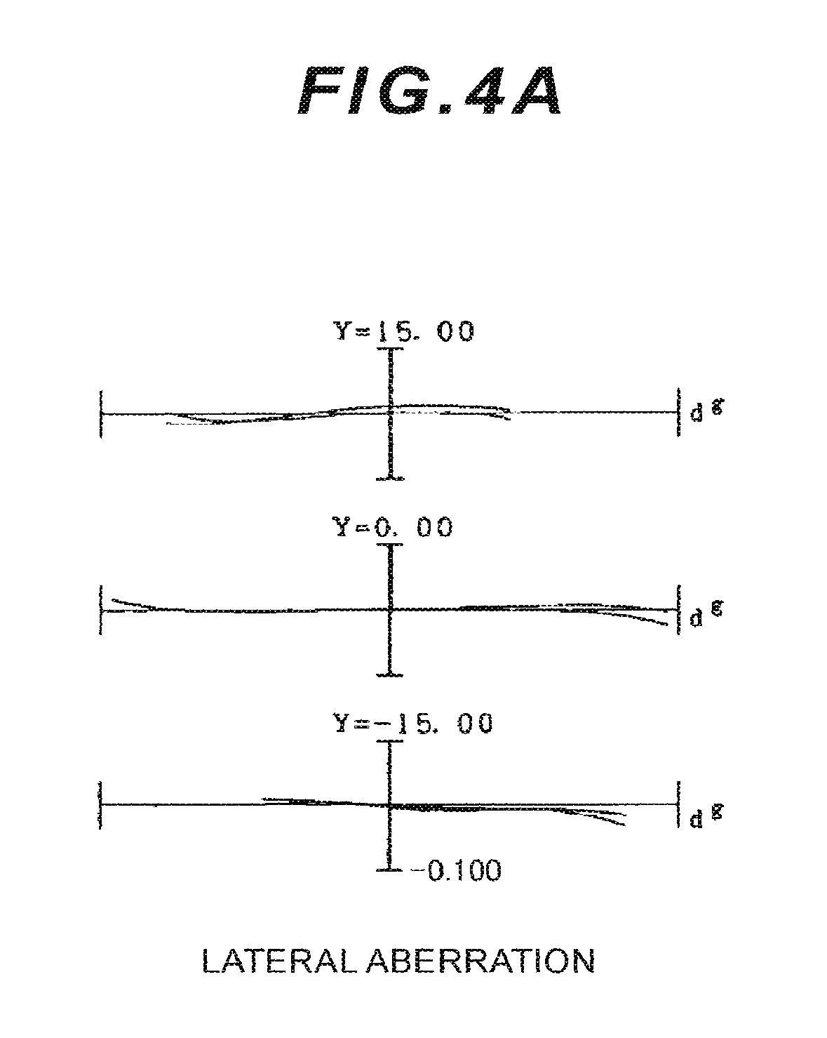
FIGS. 4A, 4B, and 4C are graphs showing lateral aberrations of the zoom optical system according to Example 1 upon focusing on infinity with image blur correction performed, respectively in the wide angle end state, the intermediate focal length state, and the telephoto end state.
FIG. 5 is a cross-sectional view with sections (W), (M), and (T) showing a zoom optical system according to Example 2 respectively in a wide angle end state, an intermediate focal length state, and a telephoto end state.
FIGS. 6A, 6B, and 6C are graphs showing various aberrations of the zoom optical system according to Example 2 upon focusing on infinity respectively in the wide angle end state, the intermediate focal length state, and the telephoto end state.
FIGS. 7A, 7B, and 7C are graphs showing various aberrations of the zoom optical system according to Example 2 upon focusing on a short distant object respectively in the wide angle end state, the intermediate focal length state, and the telephoto end state.
FIGS. 8A, 8B, and 8C are graphs showing lateral aberrations of the zoom optical system according to Example 2 upon focusing on infinity with image blur correction performed, respectively in the wide angle end state, the intermediate focal length state, and the telephoto end state.
FIG. 9 is a cross-sectional view with sections (W), (M), and (T) showing a zoom optical system according to Example 3 respectively in the wide angle end state, the intermediate focal length state, and the telephoto end state.
FIGS. 10A, 10B, and 10C are graphs showing various aberrations of the zoom optical system according to Example 3 upon focusing on infinity respectively in the wide angle end state, the intermediate focal length state, and the telephoto end state.
FIGS. 11A, 11B, and 11C are graphs showing various aberrations of the zoom optical system according to Example 3 upon focusing on a short distant object respectively in the wide angle end state, the intermediate focal length state, and the telephoto end state.
FIGS. 12A, 12B, and 12C are graphs showing lateral aberrations of the zoom optical system according to Example 3 upon focusing on infinity with image blur correction performed, respectively in the wide angle end state, the intermediate focal length state, and the telephoto end state.
FIG. 13 is a cross-sectional view with sections (W), (M), and (T) showing a zoom optical system according to Example 4 respectively in the wide angle end state, the intermediate focal length state, and the telephoto end state.
FIGS. 14A, 14B, and 14C are graphs showing various aberrations of the zoom optical system according to Example 4 upon focusing on infinity respectively in the wide angle end state, the intermediate focal length state, and the telephoto end state.
FIGS. 15A, 15B, and 15C are graphs showing various aberrations of the zoom optical system according to Example 4 upon focusing on a short distant object respectively in the wide angle end state, the intermediate focal length state, and the telephoto end state.
FIGS. 16A, 16B, and 16C are graphs showing lateral aberrations of the zoom optical system according to Example 4 upon focusing on infinity with image blur correction performed, respectively in the wide angle end state, the intermediate focal length state, and the telephoto end state.
FIG. 17 is a cross-sectional view with sections (W), (M), and (T) showing a zoom optical system according to Example 5 respectively in the wide angle end state, the intermediate focal length state, and the telephoto end state.
FIGS. 18A, 18B, and 18C are graphs showing various aberrations of the zoom optical system according to Example 5 upon focusing on infinity respectively in the wide angle end state, the intermediate focal length state, and the telephoto end state.
FIGS. 19A, 19B, and 19C are graphs showing various aberrations of the zoom optical system according to Example 5 upon focusing on a short distant object respectively in the wide angle end state, the intermediate focal length state, and the telephoto end state.
FIGS. 20A, 20B, and 20C are graphs showing lateral aberrations of the zoom optical system according to Example 5 upon focusing on infinity with image blur correction performed, respectively in the wide angle end state, the intermediate focal length state, and the telephoto end state.
FIG. 21 is a cross-sectional view with sections (W), (M), and (T) showing a zoom optical system according to Example 6 respectively in the wide angle end state, the intermediate focal length state, and the telephoto end state.
FIGS. 22A, 22B, and 22C are graphs showing various aberrations of the zoom optical system according to Example 6 upon focusing on infinity respectively in the wide angle end state, the intermediate focal length state, and the telephoto end state.
FIGS. 23A, 23B, and 23C are graphs showing various aberrations of the zoom optical system according to Example 6 upon focusing on a short distant object respectively in the wide angle end state, the intermediate focal length state, and the telephoto end state.
FIGS. 24A, 24B, and 24C are graphs showing lateral aberrations of the zoom optical system according to Example 6 upon focusing on infinity with image blur correction performed, respectively in the wide angle end state, the intermediate focal length state, and the telephoto end state.
FIG. 25 is a cross-sectional view with sections (W), (M), and (T) showing a zoom optical system according to Example 7 respectively in the wide angle end state, the intermediate focal length state, and the telephoto end state.
FIGS. 26A, 26B, and 26C are graphs showing various aberrations of the zoom optical system according to Example 7 upon focusing on infinity respectively in the wide angle end state, the intermediate focal length state, and the telephoto end state.
FIGS. 27A, 27B, and 27C are graphs showing various aberrations of the zoom optical system according to Example 7 upon focusing on a short distant object respectively in the wide angle end state, the intermediate focal length state, and the telephoto end state.
FIGS. 28A, 28B, and 28C are graphs showing lateral aberrations of the zoom optical system according to Example 7 upon focusing on infinity with image blur correction performed, respectively in the wide angle end state, the intermediate focal length state, and the telephoto end state.
FIG. 29 is a cross-sectional view with sections (W), (M), and (T) showing a zoom optical system (using a lens L51 as a vibration-proof lens group VR) according to Example 8 respectively in the wide angle end state, the intermediate focal length state, and the telephoto end state.
FIG. 30 is a cross-sectional view with sections (W), (M), and (T) showing a zoom optical system (using a lens L52 as a vibration-proof lens group VR) according to Example 8 respectively in the wide angle end state, the intermediate focal length state, and the telephoto end state.
FIGS. 31A, 31B, and 31C are graphs showing various aberrations of the zoom optical system according to Example 8 upon focusing on infinity respectively in the wide angle end state, the intermediate focal length state, and the telephoto end state.
FIGS. 32A, 32B, and 32C are graphs showing various aberrations of the zoom optical system according to Example 8 upon focusing on a short distant object respectively in the wide angle end state, the intermediate focal length state, and the telephoto end state.
FIGS. 33A, 33B, and 33C are graphs showing lateral aberrations of the zoom optical system (using the lens L51 as the vibration-proof lens group VR) according to Example 8 upon focusing on infinity with image blur correction performed, respectively in the wide angle end state, the intermediate focal length state, and the telephoto end state.
FIGS. 34A, 34B, and 34C are graphs showing lateral aberrations of the zoom optical system (using the lens L52 as the vibration-proof or image-stabilization lens group VR) according to Example 8 upon focusing on infinity with image blur correction performed, respectively in the wide angle end state, the intermediate focal length state, and the telephoto end state.
FIG. 35 is a cross-sectional view with sections (W), (M), and (T) showing a zoom optical system (using the lens L51 as the vibration-proof lens group VR) according to Example 9 respectively in the wide angle end state, the intermediate focal length state, and the telephoto end state.
FIG. 36 is a cross-sectional view with sections (W), (M), and (T) showing a zoom optical system (using the lens L52 as the vibration-proof lens group VR) according to Example 9 respectively in the wide angle end state, the intermediate focal length state, and the telephoto end state.
FIGS. 37A, 37B, and 37C are graphs showing various aberrations of the zoom optical system according to Example 9 upon focusing on infinity respectively in the wide angle end state, the intermediate focal length state, and the telephoto end state.
FIGS. 38A, 38B, and 38C are graphs showing various aberrations of the zoom optical system according to Example 9 upon focusing on a short distant object respectively in the wide angle end state, the intermediate focal length state, and the telephoto end state.
FIGS. 39A, 39B, and 39C are graphs showing lateral aberrations of the zoom optical system (using the lens L51 as the vibration-proof lens group VR) according to Example 9 upon focusing on infinity with image blur correction performed, respectively in the wide angle end state, the intermediate focal length state, and the telephoto end state.
FIGS. 40A, 40B, and 40C are graphs showing lateral aberrations of the zoom optical system (using the lens L52 as the vibration-proof lens group VR) according to Example 9 upon focusing on infinity with image blur correction performed, respectively in the wide angle end state, the intermediate focal length state, and the telephoto end state.
FIG. 41 is a cross-sectional view with sections (W), (M), and (T) showing a zoom optical system (using the lens L51 as the vibration-proof lens group VR) according to Example 10 respectively in the wide angle end state, the intermediate focal length state, and the telephoto end state.
FIG. 42 is a cross-sectional view with sections (W), (M), and (T) showing a zoom optical system (using the lens L52 as the vibration-proof lens group VR) according to Example 10 respectively in the wide angle end state, the intermediate focal length state, and the telephoto end state.
FIGS. 43A, 43B, and 43C are graphs showing various aberrations of the zoom optical system according to Example 10 upon focusing on infinity respectively in the wide angle end state, the intermediate focal length state, and the telephoto end state.
FIGS. 44A, 44B, and 44C are graphs showing various aberrations of the zoom optical system according to Example 10 upon focusing on a short distant object respectively in the wide angle end state, the intermediate focal length state, and the telephoto end state.
FIGS. 45A, 45B, and 45C are graphs showing lateral aberrations of the zoom optical system (using the lens L51 as the vibration-proof lens group VR) according to Example 10 upon focusing on infinity with image blur correction performed, respectively in the wide angle end state, the intermediate focal length state, and the telephoto end state.
FIGS. 46A, 46B, and 46C are graphs showing lateral aberrations of the zoom optical system (using the lens L52 as the vibration-proof lens group VR) according to Example 10 upon focusing on infinity with image blur correction performed, respectively in the wide angle end state, the intermediate focal length state, and the telephoto end state.
FIG. 47 is a cross-sectional view with sections (W), (M), and (T) showing a zoom optical system (using the lens L51 as the vibration-proof lens group VR) according to Example 11 respectively in the wide angle end state, the intermediate focal length state, and the telephoto end state.
FIG. 48 is a cross-sectional view with sections (W), (M), and (T) showing a zoom optical system (using the lens L52 as the vibration-proof lens group VR) according to Example 11 respectively in the wide angle end state, the intermediate focal length state, and the telephoto end state.
FIGS. 49A, 49B, and 49C are graphs showing various aberrations of the zoom optical system according to Example 11 upon focusing on infinity respectively in the wide angle end state, the intermediate focal length state, and the telephoto end state.
FIGS. 50A, 50B, and 50C are graphs showing various aberrations of the zoom optical system according to Example 11 upon focusing on a short distant object respectively in the wide angle end state, the intermediate focal length state, and the telephoto end state.
FIGS. 51A, 51B, and 51C are graphs showing lateral aberrations of the zoom optical system (using the lens L51 as the vibration-proof lens group VR) according to Example 11 upon focusing on infinity with image blur correction performed, respectively in the wide angle end state, the intermediate focal length state, and the telephoto end state.
FIGS. 52A, 52B, and 52C are graphs showing lateral aberrations of the zoom optical system (using the lens L52 as the vibration-proof lens group VR) according to Example 11 upon focusing on infinity with image blur correction performed, respectively in the wide angle end state, the intermediate focal length state, and the telephoto end state.
FIG. 53 is a cross-sectional view with sections (W), (M), and (T) showing a zoom optical system according to Example 12 respectively in the wide angle end state, the intermediate focal length state, and the telephoto end state.
FIGS. 54A, 54B, and 54C are graphs showing various aberrations of the zoom optical system according to Example 12 upon focusing on infinity respectively in the wide angle end state, the intermediate focal length state, and the telephoto end state.
FIGS. 55A, 55B, and 55C are graphs showing various aberrations of the zoom optical system according to Example 12 upon focusing on a short distant object respectively in the wide angle end state, the intermediate focal length state, and the telephoto end state.
FIGS. 56A, 56B, and 56C are graphs showing lateral aberrations of the zoom optical system according to Example 12 upon focusing on infinity with image blur correction performed, respectively in the wide angle end state, the intermediate focal length state, and the telephoto end state.
FIG. 57 is a cross-sectional view with sections (W), (M), and (T) showing a zoom optical system according to Example 13 respectively in the wide angle end state, the intermediate focal length state, and the telephoto end state.
FIGS. 58A, 58B, and 58C are graphs showing various aberrations of the zoom optical system according to Example 13 upon focusing on infinity respectively in the wide angle end state, the intermediate focal length state, and the telephoto end state.
FIGS. 59A, 59B, and 59C are graphs showing various aberrations of the zoom optical system according to Example 13 upon focusing on a short distant object respectively in the wide angle end state, the intermediate focal length state, and the telephoto end state.
FIGS. 60A, 60B, and 60C are graphs showing lateral aberrations of the zoom optical system according to Example 13 upon focusing on infinity with image blur correction performed, respectively in the wide angle end state, the intermediate focal length state, and the telephoto end state.
FIG. 61 is a cross-sectional view of a zoom optical system according to Example 14.
FIGS. 62A, 62B, and 62C are graphs showing various aberrations of the zoom optical system according to Example 14 upon focusing on infinity respectively in the wide angle end state, the intermediate focal length state, and the telephoto end state.
FIGS. 63A, 63B, and 63C are graphs showing various aberrations of the zoom optical system according to Example 14 upon focusing on a short distant object respectively in the wide angle end state, the intermediate focal length state, and the telephoto end state.
FIGS. 64A, 64B, and 64C are graphs showing lateral aberrations of the zoom optical system according to Example 14 upon focusing on infinity with image blur correction performed, respectively in the wide angle end state, the intermediate focal length state, and the telephoto end state.
FIG. 65 is a diagram illustrating a configuration of a camera including a zoom optical system according to 1st to 10th embodiments.
FIG. 66 is a diagram illustrating a method for manufacturing the zoom optical system according to the 1st embodiment.
FIG. 67 is a diagram illustrating a method for manufacturing the zoom optical system according to the 2nd embodiment.
FIG. 68 is a diagram illustrating a method for manufacturing the zoom optical system according to the 3rd embodiment.
FIG. 69 is a diagram illustrating a method for manufacturing the zoom optical system according to the 4th embodiment.
FIG. 70 is a diagram illustrating a method for manufacturing the zoom optical system according to the 5th embodiment.
FIG. 71 is a diagram illustrating a method for manufacturing the zoom optical system according to the 6th embodiment.
FIG. 72 is a diagram illustrating a method for manufacturing the zoom optical system according to the 7th embodiment.
FIG. 73 is a diagram illustrating a method for manufacturing the zoom optical system according to the 8th embodiment.
FIG. 74 is a diagram illustrating a method for manufacturing the zoom optical system according to the 9th embodiment.
FIG. 75 is a diagram illustrating a method for manufacturing the zoom optical system according to the 10th embodiment.
FIG. 76 is a cross-sectional view of a zoom optical system according to Example 15.
FIGS. 77A, 77B, and 77C are graphs showing various aberrations of the zoom optical system according to Example 15 upon focusing on infinity respectively in the wide angle end state, the intermediate focal length state, and the telephoto end state.
FIGS. 78A, 78B, and 78C are graphs showing various aberrations of the zoom optical system according to Example 15 upon focusing on a short distant object respectively in the wide angle end state, the intermediate focal length state, and the telephoto end state.
FIGS. 79A, 79B, and 79C are graphs showing coma aberrations of the zoom optical system according to Example 15 upon focusing on infinity with image blur correction performed, respectively in the wide angle end state, the intermediate focal length state, and the telephoto end state.
FIG. 80 is a cross-sectional view of a zoom optical system according to Example 16.
FIGS. 81A, 81B, and 81C are graphs showing various aberrations of the zoom optical system according to Example 16 upon focusing on infinity respectively in the wide angle end state, the intermediate focal length state, and the telephoto end state.
FIGS. 82A, 82B, and 82C are graphs showing various aberrations of the zoom optical system according to Example 16 upon focusing on a short distant object respectively in the wide angle end state, the intermediate focal length state, and the telephoto end state.
FIGS. 83A, 83B, and 83C are graphs showing coma aberrations of the zoom optical system according to Example 16 upon focusing on infinity with image blur correction performed, respectively in the wide angle end state, the intermediate focal length state, and the telephoto end state.
FIG. 84 is a cross-sectional view of a zoom optical system according to Example 17.
FIGS. 85A, 85B, and 85C are graphs showing various aberrations of the zoom optical system according to Example 17 upon focusing on infinity respectively in the wide angle end state, the intermediate focal length state, and the telephoto end state.
FIGS. 86A, 86B, and 86C are graphs showing various aberrations of the zoom optical system according to Example 17 upon focusing on a short distant object respectively in the wide angle end state, the intermediate focal length state, and the telephoto end state.
FIGS. 87A, 87B, and 87C are graphs showing coma aberrations of the zoom optical system according to Example 17 upon focusing on infinity with image blur correction performed, respectively in the wide angle end state, the intermediate focal length state, and the telephoto end state.
FIG. 88 is a cross-sectional view of a zoom optical system according to Example 18.
FIGS. 89A, 89B, and 89C are graphs showing various aberrations of the zoom optical system according to Example 18 upon focusing on infinity respectively in the wide angle end state, the intermediate focal length state, and the telephoto end state.
FIGS. 90A, 90B, and 90C are graphs showing various aberrations of the zoom optical system according to Example 18 upon focusing on a short distant object respectively in the wide angle end state, the intermediate focal length state, and the telephoto end state.
FIGS. 91A, 91B, and 91C are graphs showing coma aberrations of the zoom optical system according to Example 18 upon focusing on infinity with image blur correction performed, respectively in the wide angle end state, the intermediate focal length state, and the telephoto end state.
FIG. 92 is a cross-sectional view of a zoom optical system according to Example 19.
FIGS. 93A, 93B, and 93C are graphs showing various aberrations of the zoom optical system according to Example 19 upon focusing on infinity respectively in the wide angle end state, the intermediate focal length state, and the telephoto end state.
FIGS. 94A, 94B, and 94C are graphs showing various aberrations of the zoom optical system according to Example 19 upon focusing on a short distant object respectively in the wide angle end state, the intermediate focal length state, and the telephoto end state.
FIGS. 95A, 95B, and 95C are graphs showing coma aberrations of the zoom optical system according to Example 19 upon focusing on infinity with image blur correction performed, respectively in the wide angle end state, the intermediate focal length state, and the telephoto end state.
FIG. 96 is a cross-sectional view of a zoom optical system according to Example 20.
FIGS. 97A, 97B, and 97C are graphs showing various aberrations of the zoom optical system according to Example 20 upon focusing on infinity respectively in the wide angle end state, the intermediate focal length state, and the telephoto end state.
FIGS. 98A, 98B, and 98C are graphs showing various aberrations of the zoom optical system according to Example 20 upon focusing on a short distant object respectively in the wide angle end state, the intermediate focal length state, and the telephoto end state.
FIGS. 99A, 99B, and 99C are graphs showing coma aberrations of the zoom optical system according to Example 20 upon focusing on infinity with image blur correction performed, respectively in the wide angle end state, the intermediate focal length state, and the telephoto end state.
FIG. 100 is a cross-sectional view of a zoom optical system according to Example 21.
FIGS. 101A, 101B, and 101C are graphs showing various aberrations of the zoom optical system according to Example 21 upon focusing on infinity respectively in the wide angle end state, the intermediate focal length state, and the telephoto end state.
FIGS. 102A, 102B, and 102C are graphs showing various aberrations of the zoom optical system according to Example 21 upon focusing on a short distant object respectively in the wide angle end state, the intermediate focal length state, and the telephoto end state.
FIGS. 103A, 103B, and 103C are graphs showing coma aberrations of the zoom optical system according to Example 21 upon focusing on infinity with image blur correction performed, respectively in the wide angle end state, the intermediate focal length state, and the telephoto end state.
FIG. 104 is a cross-sectional view of a zoom optical system according to Example 22.
FIGS. 105A, 105B, and 105C are graphs showing various aberrations of the zoom optical system according to Example 22 upon focusing on infinity respectively in the wide angle end state, the intermediate focal length state, and the telephoto end state.
FIGS. 106A, 106B, and 106C are graphs showing various aberrations of the zoom optical system according to Example 22 upon focusing on a short distant object respectively in the wide angle end state, the intermediate focal length state, and the telephoto end state.
FIGS. 107A, 107B, and 107C are graphs showing coma aberrations of the zoom optical system according to Example 22 upon focusing on infinity with image blur correction performed, respectively in the wide angle end state, the intermediate focal length state, and the telephoto end state.
FIG. 108 is a cross-sectional view of a zoom optical system according to Example 23.
FIGS. 109A, 109B, and 109C are graphs showing various aberrations of the zoom optical system according to Example 23 upon focusing on infinity respectively in the wide angle end state, the intermediate focal length state, and the telephoto end state.
FIGS. 110A, 110B, and 110C are graphs showing various aberrations of the zoom optical system according to Example 23 upon focusing on a short distant object respectively in the wide angle end state, the intermediate focal length state, and the telephoto end state.
FIGS. 111A, 111B, and 111C are graphs showing coma aberrations of the zoom optical system according to Example 23 upon focusing on infinity with image blur correction performed, respectively in the wide angle end state, the intermediate focal length state, and the telephoto end state.
FIG. 112 is a cross-sectional view of a zoom optical system according to Example 24.
FIGS. 113A, 113B, and 113C are graphs showing various aberrations of the zoom optical system according to Example 24 upon focusing on infinity respectively in the wide angle end state, the intermediate focal length state, and the telephoto end state.
FIGS. 114A, 114B, and 114C are graphs showing various aberrations of the zoom optical system according to Example 24 upon focusing on a short distant object respectively in the wide angle end state, the intermediate focal length state, and the telephoto end state.
FIGS. 115A, 115B, and 115C are graphs showing coma aberrations of the zoom optical system according to Example 24 upon focusing on infinity with image blur correction performed, respectively in the wide angle end state, the intermediate focal length state, and the telephoto end state.
FIG. 116 is a cross-sectional view of a zoom optical system according to Example 25.
FIGS. 117A, 117B, and 117C are graphs showing various aberrations of the zoom optical system according to Example 25 upon focusing on infinity respectively in the wide angle end state, the intermediate focal length state, and the telephoto end state.
FIGS. 118A, 118B, and 118C are graphs showing various aberrations of the zoom optical system according to Example 25 upon focusing on a short distant object respectively in the wide angle end state, the intermediate focal length state, and the telephoto end state.
FIGS. 119A, 119B, and 119C are graphs showing coma aberrations of the zoom optical system according to Example 25 upon focusing on infinity with image blur correction performed, respectively in the wide angle end state, the intermediate focal length state, and the telephoto end state.
FIG. 120 is a cross-sectional view of a zoom optical system according to Example 26.
FIGS. 121A, 121B, and 121C are graphs showing various aberrations of the zoom optical system according to Example 26 upon focusing on infinity respectively in the wide angle end state, the intermediate focal length state, and the telephoto end state.
FIGS. 122A, 122B, and 122C are graphs showing various aberrations of the zoom optical system according to Example 26 upon focusing on a short distant object respectively in the wide angle end state, the intermediate focal length state, and the telephoto end state.
FIGS. 123A, 123B, and 123C are graphs showing coma aberrations of the zoom optical system according to Example 26 upon focusing on infinity with image blur correction performed, respectively in the wide angle end state, the intermediate focal length state, and the telephoto end state.
FIG. 124 is a cross-sectional view of a zoom optical system according to Example 27.
FIGS. 125A, 125B, and 125C are graphs showing various aberrations of the zoom optical system according to Example 27 upon focusing on infinity respectively in the wide angle end state, the intermediate focal length state, and the telephoto end state.
FIGS. 126A, 126B, and 126C are graphs showing various aberrations of the zoom optical system according to Example 27 upon focusing on a short distant object respectively in the wide angle end state, the intermediate focal length state, and the telephoto end state.
FIGS. 127A, 127B, and 127C are graphs showing coma aberrations of the zoom optical system according to Example 27 upon focusing on infinity with image blur correction performed, respectively in the wide angle end state, the intermediate focal length state, and the telephoto end state.
FIG. 128 is a cross-sectional view of a zoom optical system according to Example 28.
FIGS. 129A, 129B, and 129C are graphs showing various aberrations of the zoom optical system according to Example 28 upon focusing on infinity respectively in the wide angle end state, the intermediate focal length state, and the telephoto end state.
FIGS. 130A, 130B, and 130C are graphs showing various aberrations of the zoom optical system according to Example 28 upon focusing on a short distant object respectively in the wide angle end state, the intermediate focal length state, and the telephoto end state.
FIGS. 131A, 131B, and 131C are graphs showing coma aberrations of the zoom optical system according to Example 28 upon focusing on infinity with image blur correction performed, respectively in the wide angle end state, the intermediate focal length state, and the telephoto end state.
FIG. 132 is a cross-sectional view of a zoom optical system according to Example 29.
FIGS. 133A, 133B, and 133C are graphs showing various aberrations of the zoom optical system according to Example 29 upon focusing on infinity respectively in the wide angle end state, the intermediate focal length state, and the telephoto end state.
FIGS. 134A, 134B, and 134C are graphs showing various aberrations of the zoom optical system according to Example 29 upon focusing on a short distant object respectively in the wide angle end state, the intermediate focal length state, and the telephoto end state.
FIGS. 135A, 135B, and 135C are graphs showing coma aberrations of the zoom optical system according to Example 29 upon focusing on infinity with image blur correction performed, respectively in the wide angle end state, the intermediate focal length state, and the telephoto end state.
FIG. 136 is a cross-sectional view of a zoom optical system according to Example 30.
FIGS. 137A, 137B, and 137C are graphs showing various aberrations of the zoom optical system according to Example 30 upon focusing on infinity respectively in the wide angle end state, the intermediate focal length state, and the telephoto end state.
FIGS. 138A, 138B, and 138C are graphs showing various aberrations of the zoom optical system according to Example 30 upon focusing on a short distant object respectively in the wide angle end state, the intermediate focal length state, and the telephoto end state.
FIGS. 139A, 139B, and 139C are graphs showing coma aberrations of the zoom optical system according to Example 30 upon focusing on infinity with image blur correction performed, respectively in the wide angle end state, the intermediate focal length state, and the telephoto end state.
FIG. 140 is a cross-sectional view of a zoom optical system according to Example 31.
FIGS. 141A, 141B, and 141C are graphs showing various aberrations of the zoom optical system according to Example 31 upon focusing on infinity respectively in the wide angle end state, the intermediate focal length state, and the telephoto end state.
FIGS. 142A, 142B, and 142C are graphs showing various aberrations of the zoom optical system according to Example 31 upon focusing on a short distant object respectively in the wide angle end state, the intermediate focal length state, and the telephoto end state.
FIGS. 143A, 143B, and 143C are graphs showing coma aberrations of the zoom optical system according to Example 31 upon focusing on infinity with image blur correction performed, respectively in the wide angle end state, the intermediate focal length state, and the telephoto end state.
FIG. 144 is a cross-sectional view of a zoom optical system according to Example 32.
FIGS. 145A, 145B, and 145C are graphs showing various aberrations of the zoom optical system according to Example 32 upon focusing on infinity respectively in the wide angle end state, the intermediate focal length state, and the telephoto end state.
FIGS. 146A, 146B, and 146C are graphs showing various aberrations of the zoom optical system according to Example 32 upon focusing on a short distant object respectively in the wide angle end state, the intermediate focal length state, and the telephoto end state.
FIGS. 147A, 147B, and 147C are graphs showing coma aberrations of the zoom optical system according to Example 32 upon focusing on infinity with image blur correction performed, respectively in the wide angle end state, the intermediate focal length state, and the telephoto end state.
FIG. 148 is a cross-sectional view of a zoom optical system according to Example 33.
FIGS. 149A, 149B, and 149C are graphs showing various aberrations of the zoom optical system according to Example 33 upon focusing on infinity respectively in the wide angle end state, the intermediate focal length state, and the telephoto end state.
FIGS. 150A, 150B, and 150C are graphs showing various aberrations of the zoom optical system according to Example 33 upon focusing on a short distant object respectively in the wide angle end state, the intermediate focal length state, and the telephoto end state.
FIGS. 151A, 151B, and 151C are graphs showing coma aberrations of the zoom optical system according to Example 33 upon focusing on infinity with image blur correction performed, respectively in the wide angle end state, the intermediate focal length state, and the telephoto end state.
FIG. 152 is a cross-sectional view of a zoom optical system according to Example 34.
FIGS. 153A, 153B, and 153C are graphs showing various aberrations of the zoom optical system according to Example 34 upon focusing on infinity respectively in the wide angle end state, the intermediate focal length state, and the telephoto end state.
FIGS. 154A, 154B, and 154C are graphs showing various aberrations of the zoom optical system according to Example 34 upon focusing on a short distant object respectively in the wide angle end state, the intermediate focal length state, and the telephoto end state.
FIGS. 155A, 155B, and 155C are graphs showing coma aberrations of the zoom optical system according to Example 34 upon focusing on infinity with image blur correction performed, respectively in the wide angle end state, the intermediate focal length state, and the telephoto end state.
FIG. 156 is a cross-sectional view of a zoom optical system according to Example 35.
FIGS. 157A, 157B, and 157C are graphs showing various aberrations of the zoom optical system according to Example 35 upon focusing on infinity respectively in the wide angle end state, the intermediate focal length state, and the telephoto end state.
FIGS. 158A, 158B, and 158C are graphs showing various aberrations of the zoom optical system according to Example 35 upon focusing on a short distant object respectively in the wide angle end state, the intermediate focal length state, and the telephoto end state.
FIGS. 159A, 159B, and 159C are graphs showing coma aberrations of the zoom optical system according to Example 35 upon focusing on infinity with image blur correction performed, respectively in the wide angle end state, the intermediate focal length state, and the telephoto end state.
FIG. 160 is a cross-sectional view of a zoom optical system according to Example 36.
FIGS. 161A, 161B, and 161C are graphs showing various aberrations of the zoom optical system according to Example 36 upon focusing on infinity respectively in the wide angle end state, the intermediate focal length state, and the telephoto end state.
FIGS. 162A, 162B, and 162C are graphs showing various aberrations of the zoom optical system according to Example 36 upon focusing on a short distant object respectively in the wide angle end state, the intermediate focal length state, and the telephoto end state.
FIGS. 163A, 163B, and 163C are graphs showing coma aberrations plots of the zoom optical system according to Example 36 upon focusing on infinity with image blur correction performed, respectively in the wide angle end state, the intermediate focal length state, and the telephoto end state.
FIG. 164 is a cross-sectional view of a zoom optical system according to Example 37.
FIGS. 165A, 165B, and 165C are graphs showing various aberrations of the zoom optical system according to Example 37 upon focusing on infinity respectively in the wide angle end state, the intermediate focal length state, and the telephoto end state.
FIGS. 166A, 166B, and 166C are graphs showing various aberrations of the zoom optical system according to Example 37 upon focusing on a short distant object respectively in the wide angle end state, the intermediate focal length state, and the telephoto end state.
FIGS. 167A, 167B, and 167C are graphs showing coma aberrations of the zoom optical system according to Example 37 upon focusing on infinity with image blur correction performed, respectively in the wide angle end state, the intermediate focal length state, and the telephoto end state.
FIG. 168 is a cross-sectional view of a zoom optical system according to Example 38.
FIGS. 169A, 169B, and 169C are graphs showing various aberrations of the zoom optical system according to Example 38 upon focusing on infinity respectively in the wide angle end state, the intermediate focal length state, and the telephoto end state.
FIGS. 170A, 170B, and 170C are graphs showing various aberrations of the zoom optical system according to Example 38 upon focusing on a short distant object respectively in the wide angle end state, the intermediate focal length state, and the telephoto end state.
FIGS. 171A, 171B, and 171C are graphs showing coma aberrations of the zoom optical system according to Example 38 upon focusing on infinity with image blur correction performed, respectively in the wide angle end state, the intermediate focal length state, and the telephoto end state.
FIG. 172 is a cross-sectional view of a zoom optical system according to Example 39.
FIGS. 173A, 173B, and 173C are graphs showing various aberrations of the zoom optical system according to Example 39 upon focusing on infinity respectively in the wide angle end state, the intermediate focal length state, and the telephoto end state.
FIGS. 174A, 174B, and 174C are graphs showing various aberrations of the zoom optical system according to Example 39 upon focusing on a short distant object respectively in the wide angle end state, the intermediate focal length state, and the telephoto end state.
FIGS. 175A, 175B, and 175C are graphs showing coma aberrations of the zoom optical system according to Example 39 upon focusing on infinity with image blur correction performed, respectively in the wide angle end state, the intermediate focal length state, and the telephoto end state.
FIG. 176 is a diagram illustrating a configuration of a camera including a zoom optical system according to 11th to 14th embodiments.
FIG. 177 is a diagram illustrating a method for manufacturing the zoom optical system according to the 11th embodiment.
FIG. 178 is a diagram illustrating a method for manufacturing the zoom optical system according to the 12th embodiment.
FIG. 179 is a diagram illustrating a method for manufacturing the zoom optical system according to the 13th embodiment.
FIG. 180 is a diagram illustrating a method for manufacturing the zoom optical system according to the 14th embodiment.
DESCRIPTION OF THE EMBODIMENTS (1ST TO 10TH EMBODIMENTS)
In the description below, 1st to 10th embodiments are described with reference to drawings. A zoom optical system ZLI according to each of the embodiments includes a first lens group G1 having positive refractive power, a front-side lens group GX, an intermediate lens group GM having positive refractive power, and a rear-side lens group GR that are arranged in order from an object side. The front-side lens group GX is composed of one or more lens groups and has a negative lens group. At least part of the intermediate lens group GM is a focusing lens group GF. The rear-side lens group GR is composed of one or more lens groups. Upon zooming, the first lens group G1 is moved with respect to an image surface, the distance between the first lens group G1 and the front-side lens group GX is changed, the distance between the front-side lens group GX and the intermediate lens group GM is changed, and the distance between the intermediate lens group GM and the rear-side lens group GR is changed.
In the description of the 1st to the 10th embodiments below, a second lens group G2 is a lens group with a largest absolute value of refractive power in the negative lens group of the front-side lens group GX. A third lens group G3 is a lens group disposed closest to an image, in the front-side lens group GX. A fourth lens group G4 is the intermediate lens group GM at least partially including the focusing lens group GF. A fifth lens group G5 is a lens group disposed closest to an object, in the rear-side lens group GR. A sixth lens group G6 is a lens group disposed second closest to an object, in the rear-side lens group GR.
The 1st embodiment is described below with reference to drawings. The zoom optical system ZLI (ZL1) according to the 1st embodiment includes, as illustrated in FIG. 1, the first lens group G1 having positive refractive power, the second lens group G2 having negative refractive power, the third lens group G3 having positive refractive power, the fourth lens group G4 having positive refractive power, and the fifth lens group G5 that are arranged in order from the object side, and performs zooming by changing a distance between the lens groups. Upon zooming, the first lens group G1 is moved with respect to an image surface. Upon zooming from a wide angle end state to a telephoto end state, the fourth lens group G4 moves to the object side. Focusing is performed by moving at least part of the fourth lens group G4 as the focusing lens group GF in an optical axis direction. A forefront surface of the focusing lens group GF has a convex surface facing the object side.
With the above-described configuration including the first lens group G1 having positive refractive power, the second lens group G2 having negative refractive power, the third lens group G3 having positive refractive power, the fourth lens group G4 having positive refractive power, and the fifth lens group G5 and performing the zooming by changing a distance between the lens groups, downsizing and an excellent optical performance can be achieved. The configuration in which the first lens group G1 is moved with respect to an image surface upon zooming can achieve efficient zooming, and thus can achieve further downsizing and a higher performance. The configuration in which the fourth lens group G4 moves toward the object side with respect to the image surface upon zooming from the wide angle end state to the telephoto end state can reduce a spherical aberration. The configuration in which at least part of the fourth lens group G4 serves as the focusing lens group GF can reduce variation of image magnification, and variation of the spherical aberration and the curvature of field aberration upon focusing. The configuration in which the forefront surface of the focusing lens group GF (a lens surface of the fourth lens group G4 closest to an object) has the convex surface facing the object side can reduce variation of the spherical aberration.
The zoom optical system ZLI according to the 1st embodiment with the configuration described above satisfies the following conditional expressions (JA1) to (JA4). 0.430<|fF/fRF|<10.000 (JA1) 0.420<(-fXn)/fXR<2.000 (JA2) 0.010<fF/fW<8.000 (JA3) 32.000.ltoreq.W.omega. (JA4)
where, fF denotes a focal length of the focusing lens group GF,
fRF denotes a focal length of the lens group closest to an object in the rear-side lens group GR (the focal length of the fifth lens group G5),
fXn denotes a focal length of a lens group with the largest absolute value of refractive power in a negative lens group of the front-side lens group GX (the focal length of the second lens group G2),
fXR denotes a focal length of the lens group closest to an image in the front-side lens group GX (the focal length of the third lens group G3),
fW denotes a focal length of the entire system in the wide angle end state, and
W.omega. denotes a half angle of view in the wide angle end state.
The conditional expression (JA1) is for setting an appropriate value of the focal length of the focusing lens group GF and the focal length of the lens group closest to an object in the rear-side lens group GR (the focal length of the fifth lens group G5). A sufficient performance upon focusing on short-distant object can be achieved when the conditional expression (JA1) is satisfied.
A value higher than the upper limit value of the conditional expression (JA1) leads to a long focal length, that is, a large movement amount of the focusing lens group GF upon focusing, and thus results in large spherical aberration and curvature of field aberration. The large movement amount of the focusing lens group GF leads to a large entire length. Furthermore, the focal length of the fifth lens group G5 becomes short, and thus the fifth lens group G5 involves a large curvature of field aberration.
To guarantee the effects of the 1st embodiment, the upper limit value of the conditional expression (JA1) is preferably set to be 7.000. To more effectively guarantee the effects of the 1st embodiment, the upper limit value of the conditional expression (JA1) is preferably set to be 4.000. To more effectively guarantee the effects of the 1st embodiment, the upper limit value of the conditional expression (JA1) is preferably set to be 1.415. To more effectively guarantee the effects of the 1st embodiment, the upper limit value of the conditional expression (JA1) is preferably set to be 1.300.
A value lower than the lower limit value of the conditional expression (JA1) leads to a short focal length of the focusing lens group GF, and thus results in the focusing lens group GF involving large spherical aberration and curvature of field aberration.
To guarantee the effects of the 1st embodiment, the lower limit value of the conditional expression (JA1) is preferably set to be 0.475. To more effectively guarantee the effects of the 1st embodiment, the lower limit value of the conditional expression (JA1) is preferably set to be 0.520.
The conditional expression (JA2) is for setting an appropriate value of the focal length of a lens group with the largest absolute value of refractive power in a negative lens group of the front-side lens group GX (the focal length of the second lens group G2), and the focal length of the lens group closest to an image in the front-side lens group GX (the focal length of the third lens group G3). A sufficient performance upon focusing on infinity can be achieved when the conditional expression (JA2) is satisfied.
A value higher than the upper limit value of the conditional expression (JA2) leads to a short focal length of the third lens group G3, and thus results in the third lens group G3 involving a large spherical aberration.
To guarantee the effects of the 1st embodiment, the upper limit value of the conditional expression (JA2) is preferably set to be 1.500. To more effectively guarantee the effects of the 1st embodiment, the upper limit value of the conditional expression (JA2) is preferably set to be 1.000.
A value lower than the lower limit value of the conditional expression (JA2) leads to a short focal length of the second lens group G2, and thus results in the second lens group G2 involving large spherical aberration and curvature of field aberration.
To guarantee the effects of the 1st embodiment, the lower limit value of the conditional expression (JA2) is preferably set to be 0.424. To more effectively guarantee the effects of the 1st embodiment, the lower limit value of the conditional expression (JA2) is preferably set to be 0.428.
The conditional expression (JA3) is for setting an appropriate value of the focal length of the focusing lens group GF and the focal length of the entire system in the wide angle end state. A sufficient performance upon focusing on short-distant object can be achieved when the conditional expression (JA3) is satisfied.
A value higher than the upper limit value of the conditional expression (JA3) leads to a long focal length, that is, a large movement amount of the focusing lens group GF upon focusing, and thus results in large spherical aberration and curvature of field aberration. The large movement amount of the focusing lens group GF leads to a large entire length.
To guarantee the effects of the 1st embodiment, the upper limit value of the conditional expression (JA3) is preferably set to be 6.900. To more effectively guarantee the effects of the 1st embodiment, the upper limit value of the conditional expression (JA3) is preferably set to be 5.800.
A value lower than the lower limit value of the conditional expression (JA3) leads to a short focal length of the focusing lens group GF, and thus results in the focusing lens group GF involving large spherical aberration and curvature of field aberration.
To guarantee the effects of the 1st embodiment, the lower limit value of the conditional expression (JA3) is preferably set to be 0.550. To more effectively guarantee the effects of the 1st embodiment, the lower limit value of the conditional expression (JA3) is preferably set to be 1.100.
The conditional expression (JA4) is for setting an appropriate value of the half angle of view in the wide angle end state. A value lower than the lower limit value of the conditional expression (JA4) results in failure to successfully correct the curvature of field aberration and distortion with a wide angle of view achieved.
To guarantee the effects of the 1st embodiment, the lower limit value of the conditional expression (JA4) is preferably set to be 35.000. To more effectively guarantee the effects of the 1st embodiment, the lower limit value of the conditional expression (JA4) is preferably set to be 38.000.
Preferably, the zoom optical system ZLI according to the 1st embodiment satisfies the following conditional expression (JA5). 0.010<fF/fXR<3.400 (JA5)
where, fXR denotes a focal length of the lens group closest to an image in the front-side lens group GX (the focal length of the third lens group G3).
The conditional expression (JA5) is for setting an appropriate value of the focal length of the focusing lens group GF and the focal length of the lens group closest to an image in the front-side lens group GX (the focal length of the third lens group G3). A sufficient performance upon focusing on short-distant object can be achieved when the conditional expression (JA5) is satisfied.
A value higher than the upper limit value of the conditional expression (JA5) leads to a long focal length, that is, a large movement amount of the focusing lens group GF upon focusing, and thus results in large variation of spherical aberration and curvature of field aberration. The large movement amount of the focusing lens group GF leads to a large entire length. Furthermore, the focal length of the third lens group G3 becomes short, and thus, the third lens group G3 involves a large spherical aberration.
To guarantee the effects of the 1st embodiment, the upper limit value of the conditional expression (JA5) is preferably set to be 3.300. To more effectively guarantee the effects of the 1st embodiment, the upper limit value of the conditional expression (JA5) is preferably set to be 3.200.
A value lower than the lower limit value of the conditional expression (JA5) leads to a short focal length of the focusing lens group GF, and thus results in the focusing lens group GF involving large spherical aberration and curvature of field aberration.
To guarantee the effects of the 1st embodiment, the lower limit value of the conditional expression (JA5) is preferably set to be 0.300. To more effectively guarantee the effects of the 1st embodiment, the lower limit value of the conditional expression (JA5) is preferably set to be 0.650.
Preferably, the zoom optical system ZLI according to the 1st embodiment satisfies the following conditional expressions (JA6) and (JA7). 0.001<DXRFT/fF<1.500 (JA6) T.omega..ltoreq.20.000 (JA7)
where, DXRFT denotes a distance between a lens group closest to an image in the front-side lens group GX and the focusing lens group GF in the telephoto end state (a distance between the third lens group G3 and the focusing lens group GF in the telephoto end state), and
T.omega. denotes a half angle of view in the telephoto end state.
The conditional expression (JA6) is for setting an appropriate value of the distance between the lens group closest to an image in the front-side lens group GX and the focusing lens group GF in the telephoto end state (the distance between the third lens group G3 and the focusing lens group GF in the telephoto end state) and the focal length of the focusing lens group GF. A sufficient performance upon focusing on short-distant object as well as downsizing can be achieved when the conditional expression (JA6) is satisfied.
A value higher than the upper limit value of the conditional expression (JA6) leads to a long distance between the third lens group G3 and the focusing lens group GF in the telephoto end state, and thus results in a large entire length. Furthermore, the value leads to a short focal length of the focusing lens group GF, and thus results in the focusing lens group GF involving large spherical aberration and curvature of field aberration.
To guarantee the effects of the 1st embodiment, the upper limit value of the conditional expression (JA6) is preferably set to be 0.800. To more effectively guarantee the effects of the 1st embodiment, the upper limit value of the conditional expression (JA6) is preferably set to be 0.400. To more effectively guarantee the effects of the 1st embodiment, the upper limit value of the conditional expression (JA6) is preferably set to be 0.230.
A value lower than the lower limit value of the conditional expression (JA6) leads to a short distance between the third lens group G3 and the focusing lens group GF in the telephoto end state, and thus results in a risk of collision between the third lens group G3 and the focusing lens group GF upon focusing. Furthermore, the value results in a long focal length, that is, a large movement amount of the focusing lens group GF upon focusing, and thus results in large variation of spherical aberration and curvature of field aberration. The large movement amount of the focusing lens group GF leads to a large entire length.
To guarantee the effects of the 1st embodiment, the lower limit value of the conditional expression (JA6) is preferably set to be 0.020. To more effectively guarantee the effects of the 1st embodiment, the lower limit value of the conditional expression (JA6) is preferably set to be 0.040. To more effectively guarantee the effects of the 1st embodiment, the lower limit value of the conditional expression (JA6) is preferably set to be 0.070. To more effectively guarantee the effects of the 1st embodiment, the lower limit value of the conditional expression (JA6) is preferably set to be 0.114. To more effectively guarantee the effects of the 1st embodiment, the lower limit value of the conditional expression (JA6) is preferably set to be 0.130.
The conditional expression (JA7) is for setting an appropriate value of the half angle of view in the telephoto end state. A value higher than the upper limit value of the conditional expression (JA7) results in a failure to successfully correct the spherical aberration in the telephoto end state.
To guarantee the effects of the 1st embodiment, the upper limit value of the conditional expression (JA7) is preferably set to be 18.000. To more effectively guarantee the effects of the 1st embodiment, the upper limit value of the conditional expression (JA7) is preferably set to be 16.000.
Preferably, the zoom optical system ZLI according to the 1st embodiment satisfies the following conditional expression (JA8). 0.100<DGXR/fXR<1.500 (JA8)
where, DGXR denotes a thickness of the lens group closest to an image in the front-side lens group GX on an optical axis (the thickness of the third lens group G3 on the optical axis), and
fXR denotes a focal length of the lens group closest to an image in the front-side lens group GX (the focal length of the third lens group G3).
The conditional expression (JA8) is for setting an appropriate value of the thickness of the lens group (the third lens group G3) closest to an image in the front-side lens group GX on an optical axis (that is, a distance between a lens surface closest to an object in the third lens group G3 and a lens surface closest to an image in the third lens group G3 on the optical axis) and the focal length of the lens group closest to an image in the front-side lens group GX (the focal length of the third lens group G3). A sufficient performance upon focusing on infinity as well as excellent performance in terms of brightness can be achieved when the conditional expression (JA8) is satisfied. Furthermore, downsizing of the entire system can be achieved.
A value higher than the upper limit value of the conditional expression (JA8) leads to a short focal length of the third lens group G3, and thus results in the third lens group G3 involving a large spherical aberration. Furthermore, the value leads to the third lens group G3 with a larger thickness and thus results in a longer entire length.
To guarantee the effects of the 1st embodiment, the upper limit value of the conditional expression (JA8) is preferably set to be 1.200. To more effectively guarantee the effects of the 1st embodiment, the upper limit value of the conditional expression (JA8) is preferably set to be 1.000.
A value lower than the lower limit value of the conditional expression (JA8) leads to a long focal length, that is, a large movement amount of the third lens group G3 upon zooming, and thus results in a large variation of the spherical aberration. Furthermore, the value leads to the third lens group G3 with a smaller thickness and thus more simple configuration, and thus results in the third lens group G3 involving a large spherical aberration.
To guarantee the effects of the 1st embodiment, the lower limit value of the conditional expression (JA8) is preferably set to be 0.250. To more effectively guarantee the effects of the 1st embodiment, the lower limit value of the conditional expression (JA8) is preferably set to be 0.350.
Preferably, in the zoom optical system ZLI according to the 1st embodiment, the second lens group G2 is moved with respect to the image surface upon zooming.
The configuration can reduce variation of the spherical aberration and the curvature of field aberration upon zooming. Furthermore, efficient zooming, leading to downsizing of the optical system, can be achieved.
Preferably, in the zoom optical system ZLI according to the 1st embodiment, the third lens group G3 is moved with respect to the image surface upon zooming.
The configuration can reduce variation of the spherical aberration upon zooming. Furthermore, efficient zooming, leading to downsizing of the optical system, can be achieved.
Preferably, in the zoom optical system ZLI according to the 1st embodiment, the fifth lens group G5 is moved with respect to the image surface upon zooming.
The configuration can reduce variation of the curvature of field aberration upon zooming. Furthermore, efficient zooming, leading to downsizing of the optical system, can be achieved.
As described above, the 1st embodiment can achieve the zoom optical system ZLI featuring a small size, small variation of image magnification upon focusing, and an excellent optical performance.
Next, a camera (optical device) including the above-described zoom optical system ZLI described above will be described with reference to FIG. 65. As illustrated in FIG. 65, this camera 1 is a lens interchangeable camera (what is known as a mirrorless camera) including the above-described zoom optical system ZLI as an imaging lens 2. In the camera 1, light from an unillustrated object (subject) is collected by the imaging lens 2 and passes through an unillustrated optical low pass filter (OLPF) to be a subject image formed on an imaging plane of an imaging unit 3. Then, the subject image is photoelectrically converted into an image of the subject by a photoelectric conversion element on the imaging unit 3. The image is displayed on an Electronic view finder (EVF) 4 provided to the camera 1. Thus, a photographer can monitor the subject through the EVF 4. When the photographer presses an unillustrated release button, the image of the subject generated by the imaging unit 3 is stored in an unillustrated memory. In this manner, the photographer can capture an image of a subject with the camera 1.
The zoom optical system ZLI according to the 1st embodiment, installed in the camera 1 as the imaging lens 2, features a small size, small variation of image magnification upon focusing, and an excellent optical performance, due to its characteristic lens configuration as can be seen in Examples described later. Thus, an optical device featuring a small size, small variation of image magnification upon focusing, and an excellent optical performance can be achieved with the camera 1.
The 1st embodiment is described with the mirrorless camera as an example, but this should not be construed in a limiting sense. For example, similar or the same effects as the camera 1 can be obtained with the above-described zoom optical system ZLI installed in a single lens reflex camera in which a quick return mirror is provided to a camera main body and a subject is monitored with a view finder optical system.
Next, a method for manufacturing the above-described zoom optical system ZLI (ZL1) will be described with reference to FIG. 66. First of all, lenses are arranged in such a manner that the first lens group G1 having positive refractive power, the second lens group G2 having negative refractive power, the third lens group G3 having positive refractive power, the fourth lens group G4 having positive refractive power, and the fifth lens group G5 are arranged in a barrel in order from the object side and that the zooming is performed with the distance between the lens groups changed (step ST110). The lenses are arranged in such a manner that the first lens group G1 is moved with respect to the image surface upon zooming (step ST120). The lenses are arranged in such a manner that at least part of the fourth lens group G4 moves toward the object side upon zooming from the wide angle end state to the telephoto end state (step ST130). The lenses are arranged in such a manner that the fourth lens group G4 moves as the focusing lens group GF in the optical axis direction upon focusing (step ST140). The lenses are arranged in such a manner that the forefront surface of the focusing lens group GF has a convex surface facing the object side (step ST150). The lenses are arranged to satisfy the following conditional expressions (JA1) to (JA4) (step ST160). 0.430<|fF/fRF|<10.000 (JA1) 0.420<(-fXn)/fXR<2.000 (JA2) 0.010<fF/fW<8.000 (JA3) 32.000.ltoreq.W.omega. (JA4)
where, fF denotes a focal length of the focusing lens group GF,
fRF denotes a focal length of the lens group closest to an object in the rear-side lens group GR (the focal length of the fifth lens group G5),
fXn denotes a focal length of a lens group with the largest absolute value of refractive power in a negative lens group of the front-side lens group GX (the focal length of the second lens group G2),
fXR denotes a focal length of the lens group closest to an image in the front-side lens group GX (the focal length of the third lens group G3),
fW denotes a focal length of the entire system in the wide angle end state, and
W.omega. denotes a half angle of view in the wide angle end state.
In one example of the lens arrangement according to the 1st embodiment, as illustrated in FIG. 1, the first lens group G1 including a cemented lens including a negative meniscus lens L11 having a concave surface facing the image surface side and a biconvex lens L12, and a positive meniscus lens L13 having a convex surface facing the object side, the second lens group G2 including a negative meniscus lens L21 having a concave surface facing the image surface side, a negative meniscus lens L22 having a concave surface facing the object side, a biconvex lens L23, and a negative meniscus lens L24 having a concave surface facing the object side, the third lens group G3 including a biconvex lens L31, an aperture stop S, a cemented lens including a negative meniscus lens L32 having a concave surface facing the image surface side and a biconvex lens L33, a biconvex lens L34, and a cemented lens including a biconvex lens L35 and a biconcave lens L36, the fourth lens group G4 including a cemented lens including a biconvex lens L41 and a negative meniscus lens L42 having a concave surface facing the object side, and the fifth lens group G5 including a cemented lens including a positive meniscus lens L51 having a convex surface facing the image surface side and a biconcave lens L52, a biconvex lens L53, and a negative meniscus lens L54 having a concave surface facing the object side are arranged in order from the object side. The zoom optical system ZLI is manufactured with the lens groups thus arranged through the procedure described above.
With the manufacturing method according to the 1st embodiment, the zoom optical system ZLI featuring a small size, small variation of image magnification upon focusing, and an excellent optical performance can be manufactured.
The 2nd embodiment is described below with reference to drawings. The zoom optical system ZLI (ZL1) according to the 2nd embodiment includes, as illustrated in FIG. 1, the first lens group G1 having positive refractive power, the second lens group G2 having negative refractive power, the third lens group G3 having positive refractive power, the fourth lens group G4 having positive refractive power, and the fifth lens group G5 that are arranged in order from the object side, and performs zooming by changing a distance between the lens groups. Upon zooming, the lenses move with respect to an image surface. Upon zooming from a wide angle end state to a telephoto end state, the fourth lens group G4 moves to the object side. Upon zooming from a wide angle end state to a telephoto end state, the distance between the fourth lens group G4 and the fifth lens group G5 increases. Focusing is performed by moving at least part of the fourth lens group G4 as the focusing lens group GF in the optical axis direction.
With the above-described configuration that includes the first lens group G1 having positive refractive power, the second lens group G2 having negative refractive power, the third lens group G3 having positive refractive power, the fourth lens group G4 having positive refractive power, and the fifth lens group G5, and performs the zooming by changing a distance between the lens groups, downsizing and an excellent optical performance can be achieved. The configuration in which the lens groups move with respect to an image surface upon zooming can achieve efficient zooming, and thus can achieve further downsizing and a higher performance. The configuration in which upon zooming from the wide angle end state to the telephoto end state, the distance between the fourth lens group G4 and the fifth lens group G5 increases with the fourth lens group G4 moving toward the object side with respect to the image surface can achieve efficient zooming and reduce the variation of the spherical aberration and the curvature of field aberration. The configuration in which at least part of the fourth lens group G4 serves as the focusing lens group GF can reduce variation of variation of image magnification, the spherical aberration, and the curvature of field aberration upon focusing.
Preferably, the zoom optical system ZLI according to the 2nd embodiment satisfies the following conditional expressions (JB1) and (JB3). 0.001<(DMRT-DMRW)/fF<1.000 (JB1) 32.000.ltoreq.W.omega. (JB2) T.omega..ltoreq.20.000 (JB3)
where, DMRW denotes a distance between the intermediate lens group GM and a lens group closest to an object in the rear-side lens group GR in the wide angle end state (a distance between the fourth lens group G4 and the fifth lens group G5 in the wide angle end state),
DMRT denotes a distance between the intermediate lens group GM and a lens group closest to an object in the rear-side lens group GR in the telephoto end state (a distance between the fourth lens group G4 and the fifth lens group G5 in the telephoto end state),
W.omega. denotes a half angle of view in the wide angle end state, and
T.omega. denotes a half angle of view in the telephoto end state.
The conditional expression (JB1) is for setting an appropriate value of the difference in the distance between the intermediate lens group GM and a lens group closest to an object in the rear-side lens group GR (a distance between the fourth lens group G4 and the fifth lens group G5) between the wide angle end state and the telephoto end state, and the focal length of the focusing lens group GF. A sufficient performance upon focusing on short-distant object as well as downsizing can be achieved when the conditional expression (JB1) is satisfied.
A value higher than the upper limit value of the conditional expression (JB1) leads to a short focal length of the focusing lens group GF, and thus results in the focusing lens group GF involving large spherical aberration and curvature of field aberration.
To guarantee the effects of the 2nd embodiment, the upper limit value of the conditional expression (JB1) is preferably set to be 0.700. To more effectively guarantee the effects of the 2nd embodiment, the upper limit value of the conditional expression (JB1) is preferably set to be 0.400.
A value lower than the lower limit value of the conditional expression (JB1) results in a small difference in the distance between the fourth lens group G4 and the fifth lens group G5 between the wide angle end state and the telephoto end state, and thus leads to a less configuration in terms of zooming and a large entire length. Furthermore, the value leads to a long focal length, that is, a large movement amount of the focusing lens group GF upon focusing, and thus results in large variation of spherical aberration and curvature of field aberration. The large movement amount of the focusing lens group GF leads to a large entire length.
To guarantee the effects of the 2nd embodiment, the lower limit value of the conditional expression (JB1) is preferably set to be 0.010. To more effectively guarantee the effects of the 2nd embodiment, the lower limit value of the conditional expression (JB1) is preferably set to be 0.020.
The conditional expression (JB2) is for setting an appropriate value of the half angle of view in the wide angle end state. A value lower than the lower limit value of the conditional expression (JB2) results in failure to successfully correct the curvature of field aberration and distortion with a wide angle of view achieved.
To guarantee the effects of the 2nd embodiment, the lower limit value of the conditional expression (JB2) is preferably set to be 35.000. To more effectively guarantee the effects of the 2nd embodiment, the lower limit value of the conditional expression (JB2) is preferably set to be 38.000.
The conditional expression (JB3) is for setting an appropriate value of the half angle of view in the telephoto end state. A value higher than the upper limit value of the conditional expression (JB3) results in a failure to successfully correct the spherical aberration in the telephoto end state.
To guarantee the effects of the 2nd embodiment, the upper limit value of the conditional expression (JB3) is preferably set to be 18.000. To more effectively guarantee the effects of the 2nd embodiment, the upper limit value of the conditional expression (JB3) is preferably set to be 16.000.
Preferably, the zoom optical system ZLI according to the 2nd embodiment satisfies the following conditional expression (JB4). -10.000<fF/fRF<10.000 (JB4)
where, fF denotes a focal length of the focusing lens group GF, and
fRF denotes a focal length of the lens group closest to an object in the rear-side lens group GR (the focal length of the fifth lens group G5).
The conditional expression (JB4) is for setting an appropriate value of the focal length of the focusing lens group GF and the focal length of the lens group closest to an object in the rear-side lens group GR (the focal length of the fifth lens group G5). A sufficient performance upon focusing on short-distant object can be achieved when the conditional expression (JB4) is satisfied.
A value higher than the upper limit value of the conditional expression (JB4) leads to a long focal length, that is, a large movement amount of the focusing lens group GF upon focusing, and thus results in large spherical aberration and curvature of field aberration. The large movement amount of the focusing lens group GF leads to a large entire length. Furthermore, the focal length of the fifth lens group G5 becomes short, and thus, the fifth lens group G5 involves a large curvature of field aberration.
To guarantee the effects of the 2nd embodiment, the upper limit value of the conditional expression (JB4) is preferably set to be 7.000. To more effectively guarantee the effects of the 2nd embodiment, the upper limit value of the conditional expression (JB4) is preferably set to be 4.000.
A value lower than the lower limit value of the conditional expression (JB4) leads to a long focal length, that is, a large movement amount of the focusing lens group GF upon focusing, and thus results in large spherical aberration and curvature of field aberration. The large movement amount of the focusing lens group GF leads to a large entire length. Furthermore, the focal length of the fifth lens group G5 becomes short, and thus, the fifth lens group G5 involves a large curvature of field aberration.
To guarantee the effects of the 2nd embodiment, the lower limit value of the conditional expression (JB4) is preferably set to be -7.000. To more effectively guarantee the effects of the 2nd embodiment, the lower limit value of the conditional expression (JB4) is preferably set to be -4.000. To more effectively guarantee the effects of the 2nd embodiment, the lower limit value of the conditional expression (JB4) is preferably set to be -0.750. To more effectively guarantee the effects of the 2nd embodiment, the lower limit value of the conditional expression (JB4) is preferably set to be -0.650.
Preferably, the zoom optical system ZLI according to the 2nd embodiment satisfies the following conditional expression (JB5). 0.010<fF/fXR<10.000 (JB5)
where, fF denotes a focal length of the focusing lens group GF, and
fXR: a focal length of the lens group closest to an image in the front-side lens group GX (the focal length of the third lens group G3).
The conditional expression (JB5) is for setting an appropriate value of the focal length of the focusing lens group GF and the focal length of the lens group closest to an image in the front-side lens group GX (the focal length of the third lens group G3). A sufficient performance upon focusing on short-distant object can be achieved when the conditional expression (JB5) is satisfied.
A value higher than the upper limit value of the conditional expression (JB5) leads to a long focal length, that is, a large movement amount of the focusing lens group GF upon focusing, and thus results in large variation of spherical aberration and curvature of field aberration. The large movement amount of the focusing lens group GF leads to a large entire length. Furthermore, the focal length of the third lens group G3 becomes short, and thus, the third lens group G3 involves a large spherical aberration.
To guarantee the effects of the 2nd embodiment, the upper limit value of the conditional expression (JB5) is preferably set to be 8.000. To more effectively guarantee the effects of the 2nd embodiment, the upper limit value of the conditional expression (JB5) is preferably set to be 6.000.
A value lower than the lower limit value of the conditional expression (JB5) leads to a short focal length of the focusing lens group GF, and thus results in the focusing lens group GF involving large spherical aberration and curvature of field aberration.
To guarantee the effects of the 2nd embodiment, the lower limit value of the conditional expression (JB5) is preferably set to be 0.300. To more effectively guarantee the effects of the 2nd embodiment, the lower limit value of the conditional expression (JB5) is preferably set to be 0.650.
Preferably, the zoom optical system ZLI according to the 2nd embodiment satisfies the following conditional expression (JB6). 0.100<DGXR/fXR<1.500 (JB6)
where, DGXR denotes a thickness of the lens group closest to an image in the front-side lens group GX on the optical axis (the thickness of the third lens group G3 on the optical axis), and
fXR denotes a focal length of the lens group closest to an image in the front-side lens group GX (the focal length of the third lens group G3).
The conditional expression (JB6) is for setting an appropriate value of the thickness of the lens group (the third lens group G3) closest to an image in the front-side lens group GX on an optical axis (that is, a distance between a lens surface closest to an object in the third lens group G3 and a lens surface closest to an image in the third lens group G3 on the optical axis) and the focal length of the lens group closest to an image in the front-side lens group GX (the focal length of the third lens group G3). A sufficient performance upon focusing on infinity as well as excellent performance in terms of brightness can be achieved when the conditional expression (JB6) is satisfied. Furthermore, downsizing of the entire system can be achieved.
A value higher than the upper limit value of the conditional expression (JB6) leads to a short focal length of the third lens group G3, and thus results in the third lens group G3 involving a large spherical aberration. Furthermore, the value leads to the third lens group G3 with a larger thickness and thus results in a longer entire length.
To guarantee the effects of the 2nd embodiment, the upper limit value of the conditional expression (JB6) is preferably set to be 1.200. To more effectively guarantee the effects of the 2nd embodiment, the upper limit value of the conditional expression (JB6) is preferably set to be 1.000.
A value lower than the lower limit value of the conditional expression (JB6) leads to a long focal length, that is, a large movement amount of the third lens group G3 upon zooming, and thus results in a large variation of the spherical aberration. Furthermore, the value leads to the third lens group G3 with a smaller thickness and thus more simple configuration, and thus results in the third lens group G3 involving a large spherical aberration.
To guarantee the effects of the 2nd embodiment, the lower limit value of the conditional expression (JB6) is preferably set to be 0.250. To more effectively guarantee the effects of the 2nd embodiment, the lower limit value of the conditional expression (JB6) is preferably set to be 0.350.
In the zoom optical system ZLI according to the 2nd embodiment, the third lens group G3 preferably includes the aperture stop S and a lens that is disposed next to and on an image side of the aperture stop S and has a convex surface facing the object side.
The configuration can reduce the spherical aberration generated upon zooming.
Preferably, in the zoom optical system ZLI according to the 2nd embodiment, upon zooming from the wide angle end state to the telephoto end state, the distance between the third lens group G3 and the fourth lens group G4 increases as it gets closer to the intermediate focal length state from the wide angle end state and decreases as it gets closer to the telephoto end state from the intermediate focal length state.
The configuration can reduce the curvature of field aberration generated upon zooming.
As described above, the 2nd embodiment can achieve the zoom optical system ZLI featuring a small size, small variation of image magnification upon focusing, and an excellent optical performance.
Next, a camera (optical device) 1 including the above-described zoom optical system ZLI will be described with reference to FIG. 65. This camera 1 is the same as that in the 1st embodiment the configuration of which has been described above, and thus will not be described herein.
The zoom optical system ZLI according to the 2nd embodiment, installed in the camera 1 as the imaging lens 2, features a small size, small variation of image magnification upon focusing, and an excellent optical performance, due to its characteristic lens configuration as can be seen in Examples described later. Thus, an optical device featuring a small size, small variation of image magnification upon focusing, and an excellent optical performance can be achieved with the camera 1.
The 2nd embodiment is described with the mirrorless camera as an example, but this should not be construed in a limiting sense. For example, similar or the same effects as the camera 1 can be obtained with the above-described zoom optical system ZLI installed in a single lens reflex camera in which a quick return mirror is provided to a camera main body and a subject is monitored with a view finder optical system.
Next, a method for manufacturing the above-described zoom optical system ZLI (ZL1) will be described with reference to FIG. 67. First of all, lenses are arranged in such a manner that the first lens group G1 having positive refractive power, the second lens group G2 having negative refractive power, the third lens group G3 having positive refractive power, the fourth lens group G4 having positive refractive power, and the fifth lens group G5 are arranged in a barrel in order from the object side and that the zooming is performed with the distance between the lens groups changed (step ST210). The lenses are arranged in such a manner that the lens groups move with respect to the image surface upon zooming (step ST220). The lenses are arranged in such a manner that the fourth lens group G4 moves toward the object side upon zooming from the wide angle end state to the telephoto end state (step ST230). The lenses are arranged in such a manner that the distance between the fourth lens group G4 and the fifth lens group G5 increases upon zooming from the wide angle end state to the telephoto end state (step ST240). The lenses are arranged in such a manner that the at least part of the fourth lens group G4 moves as the focusing lens group GF in the optical axis direction upon focusing (step ST250).
In one example of the lens arrangement according to the 2nd embodiment, as illustrated in FIG. 1, the first lens group G1 including the cemented lens including the negative meniscus lens L11 having a concave surface facing the image surface side and the biconvex lens L12, and the positive meniscus lens L13 having a convex surface facing the object side, the second lens group G2 including the negative meniscus lens L21 having a concave surface facing the image surface side, the negative meniscus lens L22 having a concave surface facing the object side, the biconvex lens L23, and the negative meniscus lens L24 having a concave surface facing the object side, the third lens group G3 including the biconvex lens L31 the aperture stop S, the cemented lens including the negative meniscus lens L32 having a concave surface facing the image surface side and the biconvex lens L33, the biconvex lens L34, and the cemented lens including the biconvex lens L35 and the biconcave lens L36, the fourth lens group G4 including the cemented lens including the biconvex lens L41 and the negative meniscus lens L42 having a concave surface facing the object side, and the fifth lens group G5 including the cemented lens including a positive meniscus lens L51 having a convex surface facing the image surface side and the biconcave lens L52, the biconvex lens L53, and the negative meniscus lens L54 having a concave surface facing the object side are arranged in order from the object side. The zoom optical system ZLI is manufactured with the lens groups thus arranged through the procedure described above.
With the manufacturing method according to the 2nd embodiment, the zoom optical system ZLI featuring a small size, small variation of image magnification upon focusing, and an excellent optical performance can be manufactured.
The 3rd embodiment is described below with reference to drawings. The zoom optical system ZLI (ZL2) according to the 3rd embodiment includes, as illustrated in FIG. 5, the first lens group G1 having positive refractive power, the second lens group G2 having negative refractive power, the third lens group G3 having positive refractive power, the fourth lens group G4 having positive refractive power, the fifth lens group G5, and the sixth lens group G6 that are arranged in order from the object side, and performs zooming by changing a distance between the lens groups. Upon zooming, the first lens group G1 is moved with respect to an image surface. Upon zooming from a wide angle end state to a telephoto end state, the fourth lens group G4 moves to the object side. Upon zooming from a wide angle end state to a telephoto end state, the distance between the fourth lens group G4 and the fifth lens group G5 increases. Focusing is performed by moving at least part of the fourth lens group G4 as the focusing lens group GF in an optical axis direction.
With the above-described configuration that includes the first lens group G1 having positive refractive power, the second lens group G2 having negative refractive power, the third lens group G3 having positive refractive power, the fourth lens group G4 having positive refractive power, the fifth lens group G5, and the sixth lens group G6 and performs the zooming by changing a distance between the lens groups, downsizing and an excellent optical performance can be achieved. The configuration in which the first lens group G1 moves to an image surface upon zooming can achieve efficient zooming, and thus can achieve further downsizing and a higher performance. The configuration in which upon zooming from the wide angle end state to the telephoto end state, the distance between the fourth lens group G4 and the fifth lens group G5 increases with the fourth lens group G4 moved toward the object side with respect to the image surface can achieve efficient zooming and reduce variation of the spherical aberration and the curvature of field aberration. The configuration in which at least part of the fourth lens group G4 serves as the focusing lens group GF can reduce variation of the image magnification, the spherical aberration, and the curvature of field aberration upon focusing.
The zoom optical system ZLI according to the 3rd embodiment with the configuration described above satisfies the following conditional expressions (JC1) to (JC4). 0.170<|fF/fRF|<10.000 (JC1) 0.010<(DMRT-DMRW)/fF<1.000 (JC2) 32.000.ltoreq.W.omega. (JC3) T.omega..ltoreq.20.000 (JC4)
where, fF denotes a focal length of the focusing lens group GF,
fRF denotes a focal length of the lens group closest to an object in the rear-side lens group GR (the focal length of the fifth lens group G5),
DMRW denotes a distance between the intermediate lens group GM and a lens group closest to an object in the rear-side lens group GR in the wide angle end state (a distance between the fourth lens group G4 and the fifth lens group G5 in the wide angle end state),
DMRT denotes a distance between the intermediate lens group GM and a lens group closest to an object in the rear-side lens group GR in the telephoto end state (a distance between the fourth lens group G4 and the fifth lens group G5 in the telephoto end state),
W.omega. denotes a half angle of view in the wide angle end state, and
T.omega. denotes a half angle of view in the telephoto end state.
The conditional expression (JC1) is for setting an appropriate value of the focal length of the focusing lens group GF and the focal length of the lens group closest to an object in the rear-side lens group GR (the focal length of the fifth lens group G5). A sufficient performance upon focusing on short-distant object can be achieved when the conditional expression (JC1) is satisfied.
A value higher than the upper limit value of the conditional expression (JC1) leads to a long focal length, that is, a large movement amount of the focusing lens group GF upon focusing, and thus results in large spherical aberration and curvature of field aberration. The large movement amount of the focusing lens group GF leads to a large entire length. Furthermore, the focal length of the fifth lens group G5 becomes short, and thus, the fifth lens group G5 involves a large curvature of field aberration.
To guarantee the effects of the 3rd embodiment, the upper limit value of the conditional expression (JC1) is preferably set to be 7.000. To more effectively guarantee the effects of the 3rd embodiment, the upper limit value of the conditional expression (JC1) is preferably set to be 4.000.
A value lower than the lower limit value of the conditional expression (JC1) leads to a short focal length of the focusing lens group GF, and thus results in the focusing lens group GF involving large spherical aberration and curvature of field aberration.
To guarantee the effects of the 3rd embodiment, the lower limit value of the conditional expression (JC1) is preferably set to be 0.260. To more effectively guarantee the effects of the 3rd embodiment, the lower limit value of the conditional expression (JC1) is preferably set to be 0.350.
The conditional expression (JC2) is for setting an appropriate value of a difference in the distance between the intermediate lens group GM and a lens group closest to an object in the rear-side lens group GR (a distance between the fourth lens group G4 and the fifth lens group G5) between the wide angle end state and the telephoto end state, and the focal length of the focusing lens group GF. A sufficient performance upon focusing on short-distant object as well as downsizing can be achieved when the conditional expression (JC2) is satisfied.
A value higher than the upper limit value of the conditional expression (JC2) leads to a short focal length of the focusing lens group GF, and thus results in the focusing lens group GF involving large spherical aberration and curvature of field aberration.
To guarantee the effects of the 3rd embodiment, the upper limit value of the conditional expression (JC2) is preferably set to be 0.820. To more effectively guarantee the effects of the 3rd embodiment, the upper limit value of the conditional expression (JC2) is preferably set to be 0.640.
A value lower than the lower limit value of the conditional expression (JC2) results in a small difference in the distance between the fourth lens group G4 and the fifth lens group G5 between the wide angle end state and the telephoto end state, and thus leads to a less advantageous zooming and a large entire length. Furthermore, the value results in a long focal length, that is, a large movement amount of the focusing lens group GF upon focusing, and thus results in large variation of spherical aberration and curvature of field aberration. The large movement amount of the focusing lens group GF leads to a large entire length.
To guarantee the effects of the 3rd embodiment, the lower limit value of the conditional expression (JC2) is preferably set to be 0.016. To more effectively guarantee the effects of the 3rd embodiment, the lower limit value of the conditional expression (JC2) is preferably set to be 0.023. To more effectively guarantee the effects of the 3rd embodiment, the lower limit value of the conditional expression (JC2) is preferably set to be 0.027. To more effectively guarantee the effects of the 3rd embodiment, the lower limit value of the conditional expression (JC2) is preferably set to be 0.050.
The conditional expression (JC3) is for setting an appropriate value of the half angle of view in the wide angle end state. A value lower than the lower limit value of the conditional expression (JC3) results in failure to successfully the curvature of field aberration and distortion with a wide angle of view achieved.
To guarantee the effects of the 3rd embodiment, the lower limit value of the conditional expression (JC3) is preferably set to be 35.000. To more effectively guarantee the effects of the 3rd embodiment, the lower limit value of the conditional expression (JC3) is preferably set to be 38.000.
The conditional expression (JC4) is for setting an appropriate value of the half angle of view in the telephoto end state. A value higher than the upper limit value of the conditional expression (JC4) results in a failure to successfully correct the spherical aberration in the telephoto end state.
To guarantee the effects of the 3rd embodiment, the upper limit value of the conditional expression (JC4) is preferably set to be 18.000. To more effectively guarantee the effects of the 3rd embodiment, the upper limit value of the conditional expression (JC4) is preferably set to be 16.000.
Preferably, the zoom optical system ZLI according to the 3rd embodiment satisfies the following conditional expression (JC5). -10.000<fRF/fRF2<10.000 (JC5)
where, fRF denotes a focal length of the lens group closest to an object in the rear-side lens group GR (the focal length of the fifth lens group G5), and
fRF2 denotes a focal length of the lens group second closest to an object in the rear-side lens group GR (the focal length of the sixth lens group G6).
The conditional expression (JC5) is for setting an appropriate value of the focal length of the lens group closest to an object in the rear-side lens group GR (the focal length of the fifth lens group G5) and the focal length of the lens group second closest to an object in the rear-side lens group GR (the focal length of the sixth lens group G6). A sufficient performance upon focusing on infinity can be achieved when the conditional expression (JC5) is satisfied.
A value higher than the upper limit value of the conditional expression (JC5) results in a short focal length of the sixth lens group G6, and thus leads to the fifth lens group G5 involving a large curvature of field aberration.
To guarantee the effects of the 3rd embodiment, the upper limit value of the conditional expression (JC5) is preferably set to be 5.000. To more effectively guarantee the effects of the 3rd embodiment, the upper limit value of the conditional expression (JC5) is preferably set to be 3.000. To more effectively guarantee the effects of the 3rd embodiment, the upper limit value of the conditional expression (JC5) is preferably set to be 2.500.
A value lower than the lower limit value of the conditional expression (JC5) results in a short focal length of the sixth lens group G6, and thus leads to the fifth lens group G5 involving a large curvature of field aberration.
To guarantee the effects of the 3rd embodiment, the lower limit value of the conditional expression (JC5) is preferably set to be -5.000. To more effectively guarantee the effects of the 3rd embodiment, the lower limit value of the conditional expression (JC5) is preferably set to be -3.000. To more effectively guarantee the effects of the 3rd embodiment, the lower limit value of the conditional expression (JC5) is preferably set to be -2.500.
Preferably, the zoom optical system ZLI according to the 3rd embodiment satisfies the following conditional expression (JC6). 0.100<DGXR/fXR<1.500 (JC6)
where, DGXR denotes a thickness of the lens group closest to an image in the front-side lens group GX on an optical axis (the thickness of the third lens group G3 on the optical axis), and
fXR denotes a focal length of the lens group closest to an image in the front-side lens group GX (the focal length of the third lens group G3).
The conditional expression (JC6) is for setting an appropriate value of the thickness of the lens group (the third lens group G3) closest to an image in the front-side lens group GX on the optical axis (that is, a distance between a lens surface closest to an object in the third lens group G3 and a lens surface closest to an image in the third lens group G3 on the optical axis) and the focal length of the lens group closest to an image in the front-side lens group GX (the focal length of the third lens group G3). A sufficient performance upon focusing on infinity as well as excellent performance in terms of brightness can be achieved when the conditional expression (JC6) is satisfied. Furthermore, downsizing of the entire system can be achieved.
A value higher than the upper limit value of the conditional expression (JC6) leads to a short focal length of the third lens group G3, and thus results in the third lens group G3 involving a large spherical aberration. Furthermore, the value leads to the third lens group G3 with a larger thickness and thus results in a longer entire length.
To guarantee the effects of the 3rd embodiment, the upper limit value of the conditional expression (JC6) is preferably set to be 1.200. To more effectively guarantee the effects of the 3rd embodiment, the upper limit value of the conditional expression (JC6) is preferably set to be 1.000.
A value lower than the lower limit value of the conditional expression (JC6) leads to a long focal length, that is, a large movement amount of the third lens group G3 upon zooming upon focusing, and thus results in a large variation of the spherical aberration. Furthermore, the value leads to the third lens group G3 with a smaller thickness and thus more simple configuration, and thus results in the third lens group G3 involving a large spherical aberration.
To guarantee the effects of the 3rd embodiment, the lower limit value of the conditional expression (JC6) is preferably set to be 0.250. To more effectively guarantee the effects of the 3rd embodiment, the lower limit value of the conditional expression (JC6) is preferably set to be 0.350.
Preferably, in the zoom optical system ZLI according to the 3rd embodiment the second lens group G2 is moved with respect to the image surface upon zooming.
The configuration can reduce variation of the spherical aberration and the curvature of field aberration upon zooming. Furthermore, efficient zooming, leading to downsizing of the optical system, can be achieved.
Preferably, in the zoom optical system ZLI according to the 3rd embodiment, the third lens group G3 is moved with respect to the image surface upon zooming.
The configuration can reduce variation of the spherical aberration upon zooming. Furthermore, efficient zooming, leading to downsizing of the optical system, can be achieved.
Preferably, in the zoom optical system ZLI according to the 3rd embodiment, the fifth lens group G5 is moved with respect to the image surface upon zooming.
The configuration can reduce variation of the curvature of field aberration upon zooming. Furthermore, efficient zooming, leading to downsizing of the optical system, can be achieved.
As described above, the 3rd embodiment can achieve the zoom optical system ZLI featuring a small size, small variation of image magnification upon focusing, and an excellent optical performance.
Next, a camera (optical device) 1 including the above-described zoom optical system ZLI will be described with reference to FIG. 65. This camera 1 is the same as that in the 1st embodiment the configuration of which has been described above, and thus will not be described herein.
The zoom optical system ZLI according to the 3rd embodiment, installed in the camera 1 as the imaging lens 2, features a small size, small variation of image magnification upon focusing, and an excellent optical performance, due to its characteristic lens configuration as can be seen in Examples described later. Thus, an optical device featuring a small size, small variation of image magnification upon focusing, and an excellent optical performance can be achieved with the camera 1.
The 3rd embodiment is described with the mirrorless camera as an example, but this should not be construed in a limiting sense. For example, similar or the same effects as the camera 1 can be obtained with the above-described zoom optical system ZLI installed in a single lens reflex camera in which a quick return mirror is provided to a camera main body and a subject is monitored with a view finder optical system.
Next, a method for manufacturing the above-described zoom optical system ZLI (ZL2) will be described with reference to FIG. 68. First of all, lenses are arranged in such a manner that the first lens group G1 having positive refractive power, the second lens group G2 having negative refractive power, the third lens group G3 having positive refractive power, the fourth lens group G4 having positive refractive power, the fifth lens group G5, and the sixth lens group G6 are arranged in a barrel in order from the object side and that the zooming is performed with the distance between the lens groups changed (step ST310). The lenses are arranged in such a manner that the first lens group G1 is moved with respect to the image surface upon zooming (step ST320). The lenses are arranged in such a manner that the fourth lens group G4 moves toward the object side upon zooming from the wide angle end state to the telephoto end state (step ST330). The lenses are arranged in such a manner that the distance between the fourth lens group G4 and the fifth lens group G5 increases upon zooming from the wide angle end state to the telephoto end state (step ST340). The lenses are arranged in such a manner that the at least part of the fourth lens group G4 moves as the focusing lens group GF in the optical axis direction upon focusing (step ST350). The lenses are arranged to satisfy the following conditional expressions (JC1) to (JC4) (step ST360). 0.170<|fF/fRF|<10.000 (JC1) 0.010<(DMRT-DMRW)/fF<1.000 (JC2) 32.000.ltoreq.W.omega. (JC3) T.omega..ltoreq.20.000 (JC4)
where, fF denotes a focal length of the focusing lens group GF,
fRF denotes a focal length of the lens group closest to an object in the rear-side lens group GR (the focal length of the fifth lens group G5),
DMRW denotes a distance between the intermediate lens group GM and a lens group closest to an object in the rear-side lens group GR in the wide angle end state (a distance between the fourth lens group G4 and the fifth lens group G5 in the wide angle end state),
DMRT denotes a distance between the intermediate lens group GM and a lens group closest to an object in the rear-side lens group GR in the telephoto end state (a distance between the fourth lens group G4 and the fifth lens group G5 in the telephoto end state),
W.omega. denotes a half angle of view in the wide angle end state, and
T.omega. denotes a half angle of view in the telephoto end state.
In one example of the lens arrangement according to the 3rd embodiment, as illustrated in FIG. 5, the first lens group G1 including the cemented lens including the negative meniscus lens L11 having a concave surface facing the image surface side and the biconvex lens L12, and the positive meniscus lens L13 having a convex surface facing the object side, the second lens group G2 including the negative meniscus lens L21 having a concave surface facing the image surface side, a biconcave lens L22, the biconvex lens L23, and the negative meniscus lens L24 having a concave surface facing the object side, the third lens group G3 including the biconvex lens L31, the aperture stop S, the cemented lens including the negative meniscus lens L32 having a concave surface facing the image surface side and the biconvex lens L33, the biconvex lens L34, and the cemented lens including the biconvex lens L35 and the biconcave lens L36, the fourth lens group G4 including the cemented lens including the biconvex lens L41 and the negative meniscus lens L42 having a concave surface facing the object side, the fifth lens group G5 including the cemented lens including the positive meniscus lens L51 having a convex surface facing the image surface side and the biconcave lens L52, the biconvex lens L53, and the negative meniscus lens L54 having a concave surface facing the object side, and the sixth lens group G6 including a plano-convex lens L61 having a convex surface facing the object side are arranged in order from the object side. The zoom optical system ZLI is manufactured with the lens groups thus arranged through the procedure described above.
With the manufacturing method according to the 3rd embodiment, the zoom optical system ZLI featuring a small size, small variation of image magnification upon focusing, and an excellent optical performance can be manufactured.
The 4th embodiment is described below with reference to drawings. The zoom optical system ZLI (ZL1) according to the 4th embodiment includes, as illustrated in FIG. 1, the first lens group G1 having positive refractive power, the second lens group G2 having negative refractive power, the third lens group G3 having positive refractive power, the fourth lens group G4 having positive refractive power, and the fifth lens group G5 that are arranged in order from the object side, and performs zooming by changing a distance between the lens groups. Upon zooming, the first lens group G1 moves to an image surface. Focusing is performed by moving at least part of the fourth lens group G4 as the focusing lens group GF in an optical axis direction. A vibration-proof lens group VR is disposed closer to the image than the focusing lens group GF, and is configured to be movable with a displacement component in a direction orthogonal to the optical axis to correct image blur.
With the above-described configuration that includes the first lens group G1 having positive refractive power, the second lens group G2 having negative refractive power, the third lens group G3 having positive refractive power, the fourth lens group G4 having positive refractive power, and the fifth lens group G5, and performs the zooming by changing a distance between the lens groups, downsizing and an excellent optical performance can be achieved. The configuration in which the first lens group G1 moves to an image surface upon zooming can achieve efficient zooming, and thus can achieve further downsizing and a higher performance. The configuration in which at least part of the fourth lens group G4 serves as the focusing lens group GF can reduce variation of image magnification, and variation of the spherical aberration and the curvature of field aberration upon focusing. In the configuration in which the vibration-proof lens group VR is disposed closer to the image than the focusing lens group GF, decentering coma aberration and curvature of field aberration can be corrected upon image blur correction.
The zoom optical system ZLI according to the 4th embodiment with the configuration described above satisfies the following conditional expression (JD1). -1.500<fV/fRF<0.645 (JD1)
where, fV denotes a focal length of the vibration-proof lens group VR, and
fRF denotes a focal length of the lens group closest to an object in the rear-side lens group GR (the focal length of the fifth lens group G5).
The conditional expression (JD1) is for setting an appropriate value of the focal length of the vibration-proof lens group VR and the focal length of the lens group closest to an object in the rear-side lens group GR (the focal length of the fifth lens group G5). A sufficient vibration-proof performance can be achieved when the conditional expression (JD1) is satisfied.
A value higher than the upper limit value of the conditional expression (JD1) results in a long focal length, that is, a large movement amount of the vibration-proof lens group VR upon image blur correction, making the decentering coma aberration and curvature of field aberration difficult to correct. The larger amount of the movement of the vibration-proof lens group VR leads to a larger diameter, rendering driving control for the vibration-proof lens group VR difficult. Furthermore, the focal length of the fifth lens group G5 becomes short, and thus, the fifth lens group G5 involves a large curvature of field aberration.
To guarantee the effects of the 4th embodiment, the upper limit value of the conditional expression (JD1) is preferably set to be 0.643. To more effectively guarantee the effects of the 4th embodiment, the upper limit value of the conditional expression (JD1) is preferably set to be 0.641.
A value lower than the lower limit value of the conditional expression (JD1) results in a long focal length, that is, a large movement amount of the vibration-proof lens group VR upon image blur correction, making the decentering coma aberration and curvature of field aberration difficult to correct. The larger amount of the movement of the vibration-proof lens group VR leads to a larger diameter, rendering driving control for the vibration-proof lens group VR difficult. Furthermore, the focal length of the fifth lens group G5 becomes short, and thus, the fifth lens group G5 involves a large curvature of field aberration.
To guarantee the effects of the 4th embodiment, the lower limit value of the conditional expression (JD1) is preferably set to be -1.081. To more effectively guarantee the effects of the 4th embodiment, the lower limit value of the conditional expression (JD1) is preferably set to be -0.662.
Preferably, the zoom optical system ZLI according to the 4th embodiment satisfies the following conditional expressions (JD2) and (JD3). -1.000<DVW/fV<1.000 (JD2) 32.000.ltoreq.W.omega. (JD3)
where, DVW denotes a distance between the vibration-proof lens group VR and a next lens in the wide angle end state, and
W.omega. denotes a half angle of view in the wide angle end state.
The conditional expression (JD2) is for setting an appropriate value of the distance between the vibration-proof lens group VR and a next lens in the wide angle end state, and the focal length of the vibration-proof lens group VR. A sufficient vibration-proof performance can be achieved when the conditional expression (JD2) is satisfied.
A value higher than the upper limit value of the conditional expression (JD2) results in the distance being large making the decentering coma aberration and the curvature of field aberration generated at the vibration-proof lens group VR difficult to correct by the lenses after the vibration-proof lens group VR. Furthermore, the value results in a short focal length of the vibration-proof lens group VR, and thus leads to the vibration-proof lens group VR involving large decentering coma aberration and curvature of field aberration that are difficult to correct.
To guarantee the effects of the 4th embodiment, the upper limit value of the conditional expression (JD2) is preferably set to be 0.600. To more effectively guarantee the effects of the 4th embodiment, the upper limit value of the conditional expression (JD2) is preferably set to be 0.250.
A value lower than the lower limit value of the conditional expression (JD2) results in the distance being large making the decentering coma aberration and the curvature of field aberration generated at the vibration-proof lens group VR difficult to correct by a lens after the vibration-proof lens group VR. Furthermore, the value results in a short focal length of the vibration-proof lens group VR, and thus leads to the vibration-proof lens group VR involving large decentering coma aberration and curvature of field aberration that are difficult to correct.
To guarantee the effects of the 4th embodiment, the lower limit value of the conditional expression (JD2) is preferably set to be -0.750. To more effectively guarantee the effects of the 4th embodiment, the lower limit value of the conditional expression (JD2) is preferably set to be -0.400.
The conditional expression (JD3) is for setting an appropriate value of the half angle of view in the wide angle end state. A value lower than the lower limit value of the conditional expression (JD3) results in failure to successfully correct the curvature of field aberration and distortion with a wide angle of view achieved.
To guarantee the effects of the 4th embodiment, the lower limit value of the conditional expression (JD3) is preferably set to be 35.000. To more effectively guarantee the effects of the 4th embodiment, the lower limit value of the conditional expression (JD3) is preferably set to be 38.000.
Preferably, the zoom optical system according to the 4th embodiment satisfies the following conditional expression (JD4). 0.010<fF/fXR<10.000 (JD4)
where, fF denotes a focal length of the focusing lens group GF, and
fXR denotes a focal length of the lens group closest to an image in the front-side lens group GX (the focal length of the third lens group G3).
The conditional expression (JD4) is for setting an appropriate value of the focal length of the focusing lens group GF and the focal length of the lens group closest to an image in the front-side lens group GX (the focal length of the third lens group G3). A sufficient performance upon focusing on short-distant object can be achieved when the conditional expression (JD4) is satisfied.
A value higher than the upper limit value of the conditional expression (JD4) leads to a long focal length, that is, a large movement amount of the focusing lens group GF upon focusing, and thus results in large variation of spherical aberration and curvature of field aberration. The large movement amount of the focusing lens group GF leads to a large entire length. Furthermore, the focal length of the third lens group G3 becomes short, and thus, the third lens group G3 involves a large spherical aberration.
To guarantee the effects of the 4th embodiment, the upper limit value of the conditional expression (JD4) is preferably set to be 8.000. To more effectively guarantee the effects of the 4th embodiment, the upper limit value of the conditional expression (JD4) is preferably set to be 6.000.
A value lower than the lower limit value of the conditional expression (JD4) leads to a short focal length of the focusing lens group GF, and thus results in the focusing lens group GF involving large spherical aberration and curvature of field aberration.
To guarantee the effects of the 4th embodiment, the lower limit value of the conditional expression (JD4) is preferably set to be 0.300. To more effectively guarantee the effects of the 4th embodiment, the lower limit value of the conditional expression (JD4) is preferably set to be 0.650.
Preferably, the zoom optical system ZLI according to the 4th embodiment satisfies the following conditional expression (JD5). 0.010<(-fXn)/fXR<1.000 (JD5)
where, fXn denotes a focal length of a lens group with the largest absolute value of refractive power in a negative lens group of the front-side lens group GX (the focal length of the second lens group G2), and
fXR denotes a focal length of the lens group closest to an image in the front-side lens group GX (the focal length of the third lens group G3).
The conditional expression (JD5) is for setting an appropriate value of the focal length of a lens group with the largest absolute value of refractive power in a negative lens group of the front-side lens group GX (the focal length of the second lens group G2), and the focal length of the lens group closest to an image in the front-side lens group GX (the focal length of the third lens group G3). A sufficient performance upon focusing on infinity as well as downsizing of the entire system can be achieved when the conditional expression (JD5) is satisfied.
A value higher than the upper limit value of the conditional expression (JD5) results in a long focal length, that is, a large movement amount of the second lens group G2 upon focusing, leading to large variation of spherical aberration and curvature of field aberration. The larger movement amount of the second lens group G2 upon focusing leads to larger diameter and entire length. Furthermore, the focal length of the third lens group (G3) becomes short, and thus, the third lens group (G3) involves a large spherical aberration.
To guarantee the effects of the 4th embodiment, the upper limit value of the conditional expression (JD5) is preferably set to be 0.800. To more effectively guarantee the effects of the 4th embodiment, the upper limit value of the conditional expression (JD5) is preferably set to be 0.650.
A value lower than the lower limit value of the conditional expression (JD5) leads to a short focal length of the second lens group G2, and thus results in the second lens group G2 involving large spherical aberration and curvature of field aberration.
To guarantee the effects of the 4th embodiment, the lower limit value of the conditional expression (JD5) is preferably set to be 0.130. To more effectively guarantee the effects of the 4th embodiment, the lower limit value of the conditional expression (JD5) is preferably set to be 0.250.
Preferably, the zoom optical system ZLI according to the 4th embodiment satisfies the following conditional expression (JD6). 0.100<DGXR/fXR<1.500 (JD6)
where, DGXR denotes a thickness of the lens group closest to an image in the front-side lens group GX on an optical axis (the thickness of the third lens group G3 on the optical axis), and
fXR denotes a focal length of the lens group closest to an image in the front-side lens group GX (the focal length of the third lens group G3).
The conditional expression (JD6) is for setting an appropriate value of the thickness of the lens group (the third lens group G3) closest to an image in the front-side lens group GX on an optical axis (that is, a distance between a lens surface closest to an object in the third lens group G3 and a lens surface closest to an image in the third lens group G3 on the optical axis) and the focal length of the lens group closest to an image in the front-side lens group GX (the focal length of the third lens group G3). A sufficient performance upon focusing on infinity as well as excellent performance in terms of brightness can be achieved when the conditional expression (JD6) is satisfied. Furthermore, downsizing of the entire system can be achieved.
A value higher than the upper limit value of the conditional expression (JD6) leads to a short focal length of the third lens group G3, and thus results in the third lens group G3 involving a large spherical aberration. Furthermore, the value leads to the third lens group G3 with a larger thickness and thus results in a longer entire length.
To guarantee the effects of the 4th embodiment, the upper limit value of the conditional expression (JD6) is preferably set to be 1.200. To more effectively guarantee the effects of the 4th embodiment, the upper limit value of the conditional expression (JD6) is preferably set to be 1.000.
A value lower than the lower limit value of the conditional expression (JD6) leads to a long focal length, that is, a large movement amount of the third lens group G3 upon zooming, and thus results in a large variation of the spherical aberration. Furthermore, the value leads to the third lens group G3 with a smaller thickness and thus more simple configuration, and thus results in the third lens group G3 involving a large spherical aberration.
To guarantee the effects of the 4th embodiment, the lower limit value of the conditional expression (JD6) is preferably set to be 0.250. To more effectively guarantee the effects of the 4th embodiment, the lower limit value of the conditional expression (JD6) is preferably set to be 0.350.
Preferably, in the zoom optical system ZLI according to the 4th embodiment, the second lens group G2 is moved with respect to the image surface upon zooming.
The configuration can reduce variation of the spherical aberration and the curvature of field aberration upon zooming. Furthermore, efficient zooming, leading to downsizing of the optical system, can be achieved.
Preferably, in the zoom optical system ZLI according to the 4th embodiment, the third lens group G3 is moved with respect to the image surface upon zooming.
The configuration can reduce variation of the spherical aberration upon zooming. Furthermore, efficient zooming, leading to downsizing of the optical system, can be achieved.
Preferably, in the zoom optical system ZLI according to the 4th embodiment, the fourth lens group G4 is moved with respect to the image surface upon zooming.
The configuration can reduce variation of the spherical aberration and the curvature of field aberration upon zooming. Furthermore, efficient zooming, leading to downsizing of the optical system, can be achieved.
Preferably, in the zoom optical system ZLI according to the 4th embodiment, the fifth lens group G5 is moved with respect to the image surface upon zooming.
The configuration can reduce variation of the curvature of field aberration upon zooming. Furthermore, efficient zooming, leading to downsizing of the optical system, can be achieved.
Preferably, in the zoom optical system ZLI according to the 4th embodiment, part of the fifth lens group G5 is preferably the vibration-proof lens group VR.
The configuration is effective for correcting the decentering coma aberration and the curvature of field aberration upon image blur correction. The vibration-proof lens group VR is part of the group and is not the group as a whole, and thus can have a small size.
As described above, the 4th embodiment can achieve the zoom optical system ZLI featuring a small size, small variation of image magnification upon focusing, and an excellent optical performance.
Next, a camera (optical device) 1 including the above-described zoom optical system ZLI will be described with reference to FIG. 65. This camera 1 is the same as that in the 1st embodiment the configuration of which has been described above, and thus will not be described herein.
The zoom optical system ZLI according to the 4th embodiment, installed in the camera 1 as the imaging lens 2, features a small size, and small variation of image magnification upon focusing, and an excellent optical performance, due to its characteristic lens configuration as can be seen in Examples described later. Thus, an optical device featuring a small size, small variation of image magnification upon focusing, and an excellent optical performance can be achieved with the camera 1.
The 4th embodiment is described with the mirrorless camera as an example, but this should not be construed in a limiting sense. For example, similar or the same effects as the camera 1 can be obtained with the above-described zoom optical system ZLI installed in a single lens reflex camera in which a quick return mirror is provided to a camera main body and a subject is monitored with a view finder optical system.
Next, a method for manufacturing the above-described zoom optical system ZLI (ZL1) will be described with reference to FIG. 69. First of all, lenses are arranged in such a manner that the first lens group G1 having positive refractive power, the second lens group G2 having negative refractive power, the third lens group G3 having positive refractive power, the fourth lens group G4 having positive refractive power, and the fifth lens group G5 are arranged in a barrel in order from the object side and that the zooming is performed with the distance between the lens groups changed (step ST410). The lenses are arranged in such a manner that the first lens group G1 is moved with respect to the image surface upon zooming (step ST420). The lenses are arranged in such a manner that the at least part of the fourth lens group G4 moves as the focusing lens group GF in the optical axis direction upon focusing (step ST430). The lenses are arranged in such a manner that the vibration-proof lens group VR is disposed closer to the image than the focusing lens group GF, and is configured to be movable with a displacement component in a direction orthogonal to the optical axis to correct image blur (step ST440). The lenses are arranged to satisfy the following conditional expression (JD1) (step ST450). -1.500<fV/fRF<0.645 (JD1)
where, fV: a focal length of the vibration-proof lens group VR, and
fRF: a focal length of the lens group closest to an object in the rear-side lens group GR (the focal length of the fifth lens group G5).
In one example of the lens arrangement according to the 4th embodiment, as illustrated in FIG. 1, the first lens group G1 including the cemented lens including the negative meniscus lens L11 having a concave surface facing the image surface side and the biconvex lens L12, and the positive meniscus lens L13 having a convex surface facing the object side, the second lens group G2 including the negative meniscus lens L21 having a concave surface facing the image surface side, the negative meniscus lens L22 having a concave surface facing the object side, the biconvex lens L23, and the negative meniscus lens L24 having a concave surface facing the object side, the third lens group G3 including the biconvex lens L31, the aperture stop S, the cemented lens including the negative meniscus lens L32 having a concave surface facing the image surface side and the biconvex lens L33, the biconvex lens L34, and the cemented lens including the biconvex lens L35 and the biconcave lens L36, the fourth lens group G4 including the cemented lens including the biconvex lens L41 and the negative meniscus lens L42 having a concave surface facing the object side, and the fifth lens group G5 including the cemented lens including the positive meniscus lens L51 having a convex surface facing the image surface side and the biconcave lens L52, the biconvex lens L53, and the negative meniscus lens L54 having a concave surface facing the object side are arranged in order from the object side. The cemented lens including the lenses L51 and L52 forming the fifth lens group G5 serves as the vibration-proof lens group VR. The zoom optical system ZLI is manufactured with the lens groups thus arranged through the procedure described above.
With the manufacturing method according to the 4th embodiment, the zoom optical system ZLI featuring a small size, small variation of image magnification upon focusing, and an excellent optical performance can be manufactured.
The 5th embodiment is described below with reference to drawings. The zoom optical system ZLI (ZL1) according to the 5th embodiment includes, as illustrated in FIG. 1, the first lens group G1 having positive refractive power, the second lens group G2 having negative refractive power, the third lens group G3 having positive refractive power, the fourth lens group G4 having positive refractive power, and the fifth lens group G5 that are arranged in order from the object side, and performs zooming by changing a distance between the lens groups. Upon zooming, the first lens group G1 moves to an image surface. Focusing is performed by moving at least part of the fourth lens group G4 as the focusing lens group GF in an optical axis direction. The vibration-proof lens group VR is disposed closer to the image than the focusing lens group GF, and is configured to be movable with a displacement component in a direction orthogonal to the optical axis to correct image blur.
With the above-described configuration that includes the first lens group G1 having positive refractive power, the second lens group G2 having negative refractive power, the third lens group G3 having positive refractive power, the fourth lens group G4 having positive refractive power, and the fifth lens group G5, and performs the zooming by changing a distance between the lens groups, downsizing and an excellent optical performance can be achieved. The configuration in which the first lens group G1 moves to an image surface upon zooming can achieve efficient zooming, and thus can achieve further downsizing and a higher performance. The configuration in which at least part of the fourth lens group G4 serves as the focusing lens group GF can reduce variation of image magnification, and variation of the spherical aberration and the curvature of field aberration upon focusing. In the configuration in which the vibration-proof lens group VR is disposed closer to the image than the focusing lens group GF, decentering coma aberration and curvature of field aberration can be corrected upon image blur correction.
A zoom optical system ZLI according to the 5th embodiment with the configuration described above satisfies the following conditional expressions (JE1) and (JE2). -0.150<DVW/fV<1.000 (JE1) 32.000.ltoreq.W.omega. (JE2)
where, DVW denotes a distance between the vibration-proof lens group VR and a next lens in the wide angle end state,
fV denotes a focal length of the vibration-proof lens group VR, and
W.omega. denotes a half angle of view in the wide angle end state.
The conditional expression (JE1) is for setting an appropriate value of the distance between the vibration-proof lens group VR and a next lens in the wide angle end state, and the focal length of the vibration-proof lens group VR. A sufficient vibration-proof performance can be achieved when the conditional expression (JE1) is satisfied.
A value higher than the upper limit value of the conditional expression (JE1) results in the distance being large making the decentering coma aberration and the curvature of field aberration generated at the vibration-proof lens group VR difficult to correct by a lens after the vibration-proof lens group VR. Furthermore, the value results in a short focal length of the vibration-proof lens group VR, and thus leads to the vibration-proof lens group VR involving large decentering coma aberration and curvature of field aberration that are difficult to correct.
To guarantee the effects of the 5th embodiment, the upper limit value of the conditional expression (JE1) is preferably set to be 0.691. To more effectively guarantee the effects of the 5th embodiment, the upper limit value of the conditional expression (JE1) is preferably set to be 0.383.
A value lower than the lower limit value of the conditional expression (JE1) results in the distance being large making the decentering coma aberration and the curvature of field aberration generated at the vibration-proof lens group VR difficult to correct by a lens after the vibration-proof lens group VR. Furthermore, the value results in a short focal length of the vibration-proof lens group VR, and thus leads to the vibration-proof lens group VR involving large decentering coma aberration and curvature of field aberration that are difficult to correct.
To guarantee the effects of the 5th embodiment, the lower limit value of the conditional expression (JE1) is preferably set to be -0.141. To more effectively guarantee the effects of the 5th embodiment, the lower limit value of the conditional expression (JE1) is preferably set to be -0.132.
The conditional expression (JE2) is for setting an appropriate value of the half angle of view in the wide angle end state. A value lower than the lower limit value of the conditional expression (JE2) results in failure to successfully correct the curvature of field aberration and distortion with a wide angle of view achieved.
To guarantee the effects of the 5th embodiment, the lower limit value of the conditional expression (JE2) is preferably set to be 35.000. To more effectively guarantee the effects of the 5th embodiment, the lower limit value of the conditional expression (JE2) is preferably set to be 38.000.
Preferably, the zoom optical system ZLI according to the 5th embodiment satisfies the following conditional expression (JE3). 0.001<fF/fW<20.000 (JE3)
where, fF denotes a focal length of the focusing lens group GF, and
fW denotes a focal length of the entire system in the wide angle end state.
The conditional expression (JE3) is for setting an appropriate value of the focal length of the focusing lens group GF and the focal length of the entire system in the wide angle end state. A sufficient performance upon focusing on short-distant object can be achieved when the conditional expression (JE3) is satisfied.
A value higher than the upper limit value of the conditional expression (JE3) leads to a long focal length, that is, a large movement amount of the focusing lens group GF upon focusing, and thus results in large variation of spherical aberration and curvature of field aberration. The large movement amount of the focusing lens group GF leads to a large entire length.
To guarantee the effects of the 5th embodiment, the upper limit value of the conditional expression (JE3) is preferably set to be 15.000. To more effectively guarantee the effects of the 5th embodiment, the upper limit value of the conditional expression (JE3) is preferably set to be 10.000. To more effectively guarantee the effects of the 5th embodiment, the upper limit value of the conditional expression (JE3) is preferably set to be 8.500.
A value lower than the lower limit value of the conditional expression (JE3) leads to a short focal length of the focusing lens group GF, and thus results in the focusing lens group GF involving large spherical aberration and curvature of field aberration.
To guarantee the effects of the 5th embodiment, the lower limit value of the conditional expression (JE3) is preferably set to be 0.400. To more effectively guarantee the effects of the 5th embodiment, the lower limit value of the conditional expression (JE3) is preferably set to be 0.800. To more effectively guarantee the effects of the 5th embodiment, the lower limit value of the conditional expression (JE3) is preferably set to be 1.150.
Preferably, the zoom optical system ZLI according to the 5th embodiment satisfies the following conditional expression (JE4). -1.000<fV/fRF<2.000 (JE4)
where, fRF: a focal length of the lens group closest to an object in the rear-side lens group GR (the focal length of the fifth lens group G5).
The conditional expression (JE4) is for setting an appropriate value of the focal length of the vibration-proof lens group VR and the focal length of the lens group closest to an object in the rear-side lens group GR (the focal length of the fifth lens group G5). A sufficient vibration-proof performance can be achieved when the conditional expression (JE4) is satisfied.
A value higher than the upper limit value of the conditional expression (JE4) results in a long focal length, that is, a large movement amount of the vibration-proof lens group VR upon image blur correction, making the decentering coma aberration and curvature of field aberration difficult to correct. The larger amount of the movement of the vibration-proof lens group VR leads to a larger diameter, rendering driving control for the vibration-proof lens group VR difficult. Furthermore, the focal length of the fifth lens group G5 becomes short, and thus, the fifth lens group G5 involves a large curvature of field aberration.
To guarantee the effects of the 5th embodiment, the upper limit value of the conditional expression (JE4) is preferably set to be 1.600. To more effectively guarantee the effects of the 5th embodiment, the upper limit value of the conditional expression (JE4) is preferably set to be 1.300.
A value lower than the lower limit value of the conditional expression (JE4) results in a long focal length, that is, a large movement amount of the vibration-proof lens group VR upon image blur correction, making the decentering coma aberration and curvature of field aberration difficult to correct. The larger amount of the movement of the vibration-proof lens group VR leads to a larger diameter, rendering driving control for the vibration-proof lens group VR difficult. Furthermore, the focal length of the fifth lens group G5 becomes short, and thus, the fifth lens group G5 involves a large curvature of field aberration.
To guarantee the effects of the 5th embodiment, the lower limit value of the conditional expression (JE4) is preferably set to be -0.750. To more effectively guarantee the effects of the 5th embodiment, the lower limit value of the conditional expression (JE4) is preferably set to be -0.435.
Preferably, the zoom optical system ZLI according to the 5th embodiment satisfies the following conditional expression (JE5). 0.010<fF/fXR<10.000 (JE5)
where, fF denotes a focal length of the focusing lens group GF, and
fXR denotes a focal length of the lens group closest to an image in the front-side lens group GX (the focal length of the third lens group G3).
The conditional expression (JE5) is for setting an appropriate value of the focal length of the focusing lens group GF and the focal length of the lens group closest to an image in the front-side lens group GX (the focal length of the third lens group G3). A sufficient performance upon focusing on short-distant object can be achieved when the conditional expression (JE5) is satisfied.
A value higher than the upper limit value of the conditional expression (JE5) leads to a long focal length, that is, a large movement amount of the focusing lens group GF upon focusing, and thus results in large variation of spherical aberration and curvature of field aberration. The large movement amount of the focusing lens group GF leads to a large entire length. Furthermore, the focal length of the third lens group G3 becomes short, and thus, the third lens group G3 involves a large spherical aberration.
To guarantee the effects of the 5th embodiment, the upper limit value of the conditional expression (JE5) is preferably set to be 8.000. To more effectively guarantee the effects of the 5th embodiment, the upper limit value of the conditional expression (JE5) is preferably set to be 6.000.
A value lower than the lower limit value of the conditional expression (JE5) leads to a short focal length of the focusing lens group GF, and thus results in the focusing lens group GF involving large spherical aberration and curvature of field aberration.
To guarantee the effects of the 5th embodiment, the lower limit value of the conditional expression (JE5) is preferably set to be 0.300. To more effectively guarantee the effects of the 5th embodiment, the lower limit value of the conditional expression (JE5) is preferably set to be 0.650.
Preferably, the zoom optical system ZLI according to the 5th embodiment satisfies the following conditional expression (JE6). 0.100<DGXR/fXR<1.500 (JE6)
where, DGXR denotes a thickness of the lens group closest to an image in the front-side lens group GX on an optical axis (the thickness of the third lens group G3 on the optical axis), and
fXR denotes a focal length of the lens group closest to an image in the front-side lens group GX (the focal length of the third lens group G3).
The conditional expression (JE6) is for setting an appropriate value of the thickness of the lens group (the third lens group G3) closest to an image in the front-side lens group GX on an optical axis (that is, a distance between a lens surface closest to an object in the third lens group G3 and a lens surface closest to an image in the third lens group G3 on the optical axis) and the focal length of the lens group closest to an image in the front-side lens group GX (the focal length of the third lens group G3). A sufficient performance upon focusing on infinity as well as excellent performance in terms of brightness can be achieved when the conditional expression (JE6) is satisfied. Furthermore, downsizing of the entire system can be achieved.
A value higher than the upper limit value of the conditional expression (JE6) leads to a short focal length of the third lens group G3, and thus results in the third lens group G3 involving a large spherical aberration. Furthermore, the value leads to the third lens group G3 with a larger thickness and thus results in a longer entire length.
To guarantee the effects of the 5th embodiment, the upper limit value of the conditional expression (JE6) is preferably set to be 1.200. To more effectively guarantee the effects of the 5th embodiment, the upper limit value of the conditional expression (JE6) is preferably set to be 1.000.
A value lower than the lower limit value of the conditional expression (JE6) leads to a long focal length, that is, a large movement amount of the third lens group G3 upon zooming, and thus results in a large variation of the spherical aberration. Furthermore, the value leads to the third lens group G3 with a smaller thickness and thus more simple configuration, and thus results in the third lens group G3 involving a large spherical aberration.
To guarantee the effects of the 5th embodiment, the lower limit value of the conditional expression (JE6) is preferably set to be 0.250. To more effectively guarantee the effects of the 5th embodiment, the lower limit value of the conditional expression (JE6) is preferably set to be 0.350.
Preferably, the zoom optical system ZLI according to the 5th embodiment satisfies the following conditional expression (JE7). 0.390<DXnW/ZD1<5.000 (JE7)
where, DXnW denotes a distance between a lens group with the largest absolute value of the refractive power in the negative lens groups of the front-side lens group GX and a lens group closest to the image in the front-side lens group GX in the wide angle end state, and
ZD1 denotes a movement amount of the first lens group G1 upon zooming from the wide angle end state to the telephoto end state.
The conditional expression (JE7) is for setting an appropriate value of the distance between a lens group (second lens group G2) with the largest absolute value of the refractive power in the negative lens groups of the front-side lens group GX and the lens group (third lens group G3) closest to the image in the front-side lens group GX in the wide angle end state, and the movement amount of the first lens group G1 upon zooming from the wide angle end state to the telephoto end state. An excellent optical performance can be achieved when the conditional expression (JE7) is satisfied.
A value higher than the upper limit value of the conditional expression (JE7) results in a large distance between a lens group with the largest absolute value of the refractive power in the negative lens groups of the front-side lens group GX and the lens group closest to the image in the front-side lens group GX (that is, a distance between the second lens group G2 and the third lens group G3), and thus results in curvature of field aberration in the wide angle end state.
To guarantee the effects of the 5th embodiment, the upper limit value of the conditional expression (JE7) is preferably set to be 4.000. To more effectively guarantee the effects of the 5th embodiment, the upper limit value of the conditional expression (JE7) is preferably set to be 3.000. To more effectively guarantee the effects of the 5th embodiment, the upper limit value of the conditional expression (JE7) is preferably set to be 2.000. To more effectively guarantee the effects of the 5th embodiment, the upper limit value of the conditional expression (JE7) is preferably set to be 1.000.
A value lower than the lower limit value of the conditional expression (JE7) leads to a movement amount of the first lens group G1, and thus results in a zooming involving a large variation of the curvature of field aberration.
To guarantee the effects of the 5th embodiment, the lower limit value of the conditional expression (JE7) is preferably set to be 0.400. To more effectively guarantee the effects of the 5th embodiment, the lower limit value of the conditional expression (JE7) is preferably set to be 0.410. To more effectively guarantee the effects of the 5th embodiment, the lower limit value of the conditional expression (JE7) is preferably set to be 0.420. To more effectively guarantee the effects of the 5th embodiment, the lower limit value of the conditional expression (JE7) is preferably set to be 0.430.
Preferably, in the zoom optical system ZLI according to the 5th embodiment, the second lens group G2 is moved with respect to the image surface upon zooming.
The configuration can reduce variation of the spherical aberration and the curvature of field aberration upon zooming. Furthermore, efficient zooming, leading to downsizing of the optical system, can be achieved.
Preferably, in the zoom optical system ZLI according to the 5th embodiment, the third lens group G3 is moved with respect to the image surface upon zooming.
The configuration can reduce variation of the spherical aberration upon zooming. Furthermore, efficient zooming, leading to downsizing of the optical system, can be achieved.
Preferably, in the zoom optical system ZLI according to the 5th embodiment, the fourth lens group G4 is moved with respect to the image surface upon zooming.
The configuration can reduce variation of the spherical aberration and the curvature of field aberration upon zooming. Furthermore, efficient zooming, leading to downsizing of the optical system, can be achieved.
Preferably, in the zoom optical system ZLI according to the 5th embodiment, the fifth lens group G5 is moved with respect to the image surface upon zooming.
The configuration can reduce variation of the curvature of field aberration upon zooming. Furthermore, efficient zooming, leading to downsizing of the optical system, can be achieved.
Preferably, in the zoom optical system ZLI according to the 5th embodiment, part of the fifth lens group G5 is preferably the vibration-proof lens group VR.
The configuration is effective for correcting the decentering coma aberration and the curvature of field aberration upon image blur correction. The vibration-proof lens group VR is part of the group and is not the group as a whole, and thus can have a small size.
As described above, the 5th embodiment can achieve the zoom optical system ZLI featuring a small size, small variation of image magnification upon focusing, and an excellent optical performance.
Next, a camera (optical device) 1 including the above-described zoom optical system ZLI will be described with reference to FIG. 65. This camera 1 is the same as that in the 1st embodiment the configuration of which has been described above, and thus will not be described herein.
The zoom optical system ZLI according to the 5th embodiment, installed in the camera 1 as the imaging lens 2, features a small size, small variation of image magnification upon focusing, and an excellent optical performance, due to its characteristic lens configuration as can be seen in Examples described later. Thus, an optical device featuring a small size, small variation of image magnification upon focusing, and an excellent optical performance can be achieved with the camera 1.
The 5th embodiment is described with the mirrorless camera as an example, but this should not be construed in a limiting sense. For example, similar or the same effects as the camera 1 can be obtained with the above-described zoom optical system ZLI installed in a single lens reflex camera in which a quick return mirror is provided to a camera main body and a subject is monitored with a view finder optical system.
Next, a method for manufacturing the above-described zoom optical system ZLI (ZL1) will be described with reference to FIG. 70. First of all, lenses are arranged in such a manner that the first lens group G1 having positive refractive power, the second lens group G2 having negative refractive power, the third lens group G3 having positive refractive power, the fourth lens group G4 having positive refractive power, and the fifth lens group G5 are arranged in a barrel in order from the object side and that the zooming is performed with the distance between the lens groups changed (step ST510). The lenses are arranged in such a manner that the first lens group G1 is moved with respect to the image surface upon zooming (step ST520). The lenses are arranged in such a manner that the at least part of the fourth lens group G4 moves as the focusing lens group GF in the optical axis direction upon focusing (step ST530). The lenses are arranged in such a manner that the vibration-proof lens group VR is disposed closer to the image than the focusing lens group GF, and is configured to be movable with a displacement component in a direction orthogonal to the optical axis to correct image blur (step ST540). The lenses are arranged to satisfy the following conditional expressions (JE1) and (JE2) (step ST550). 0.150<DVW/fV<1.000 (JE1) 32.000.ltoreq.W.omega. (JE2)
where, DVW denotes a distance between the vibration-proof lens group VR and a next lens in the wide angle end state,
fV denotes a focal length of the vibration-proof lens group VR, and
W.omega. denotes a half angle of view in the wide angle end state.
In one example of the lens arrangement according to the 5th embodiment, as illustrated in FIG. 1, the first lens group G1 including the cemented lens including the negative meniscus lens L11 having a concave surface facing the image surface side and the biconvex lens L12, and the positive meniscus lens L13 having a convex surface facing the object side, the second lens group G2 including the negative meniscus lens L21 having a concave surface facing the image surface side, the negative meniscus lens L22 having a concave surface facing the object side, the biconvex lens L23, and the negative meniscus lens L24 having a concave surface facing the object side, the third lens group G3 including the biconvex lens L31, the aperture stop S, the cemented lens including the negative meniscus lens L32 having a concave surface facing the image surface side and the biconvex lens L33, the biconvex lens L34, and the cemented lens including the biconvex lens L35 and the biconcave lens L36, the fourth lens group G4 including the cemented lens including the biconvex lens L41 and the negative meniscus lens L42 having a concave surface facing the object side, and the fifth lens group G5 including the cemented lens including the positive meniscus lens L51 having a convex surface facing the image surface side and the biconcave lens L52, the biconvex lens L53, and the negative meniscus lens L54 having a concave surface facing the object side are arranged in order from the object side. The cemented lens including the lenses L51 and L52 forming the fifth lens group G5 serves as the vibration-proof lens group VR. The zoom optical system ZLI is manufactured with the lens groups thus arranged through the procedure described above.
With the manufacturing method according to the 5th embodiment, the zoom optical system ZLI featuring a small size, small variation of image magnification upon focusing, and an excellent optical performance can be manufactured.
The 6th embodiment is described below with reference to drawings. The zoom optical system ZLI (ZL2) according to the 6th embodiment includes, as illustrated in FIG. 5, the first lens group G1 having positive refractive power, the second lens group G2 having negative refractive power, the third lens group G3 having positive refractive power, the fourth lens group G4 having positive refractive power, the fifth lens group G5, and the sixth lens group G6 that are arranged in order from the object side, and performs zooming by changing a distance between the lens groups. Upon zooming, the first lens group G1 moves to an image surface. Focusing is performed by moving at least part of the fourth lens group G4 as the focusing lens group GF in an optical axis direction. The vibration-proof lens group VR is disposed closer to the image than the focusing lens group GF, and is configured to be movable with a displacement component in a direction orthogonal to the optical axis to correct image blur.
With the above-described configuration that includes the first lens group G1 having positive refractive power, the second lens group G2 having negative refractive power, the third lens group G3 having positive refractive power, the fourth lens group G4 having positive refractive power, the fifth lens group G5, and the sixth lens group G6 and performs the zooming by changing a distance between the lens groups, downsizing and an excellent optical performance can be achieved. The configuration in which the first lens group G1 moves to an image surface upon zooming can achieve efficient zooming, and thus can achieve further downsizing and a higher performance. The configuration in which at least part of the fourth lens group G4 serves as the focusing lens group GF can reduce variation of image magnification and variation of the spherical aberration and the curvature of field aberration upon focusing. In the configuration in which the vibration-proof lens group VR is disposed closer to the image than the focusing lens group GF, decentering coma aberration and curvature of field aberration can be corrected upon image blur correction.
Preferably, the zoom optical system ZLI according to the 6th embodiment satisfies the following conditional expression (JF1). -20.000<fF/fV<20.000 (JF1)
where, fF denotes a focal length of the focusing lens group GF, and
fV denotes a focal length of the vibration-proof lens group VR.
The conditional expression (JF1) is for setting an appropriate value of the focal length of the focusing lens group GF and the focal length of the vibration-proof lens group.
A value higher than the upper limit value of the conditional expression (JF1) leads to a long focal length, that is, a large movement amount of the focusing lens group GF upon focusing, and thus results in large variation of spherical aberration and curvature of field aberration. The large movement amount of the focusing lens group GF leads to a large entire length. Furthermore, the value results in a short focal length of the vibration-proof lens group VR, and thus leads to the vibration-proof lens group VR involving large decentering coma aberration and curvature of field aberration.
To guarantee the effects of the 6th embodiment, the upper limit value of the conditional expression (JF1) is preferably set to be 15.000. To more effectively guarantee the effects of the 6th embodiment, the upper limit value of the conditional expression (JF1) is preferably set to be 10.000.
A value lower than the lower limit value of the conditional expression (JF1) leads to a long focal length, that is, a large movement amount of the focusing lens group GF upon focusing, and thus results in large variation of spherical aberration and curvature of field aberration. The large movement amount of the focusing lens group GF leads to a large entire length. Furthermore, the value results in a short focal length of the vibration-proof lens group VR, and thus leads to the vibration-proof lens group VR involving large decentering coma aberration and curvature of field aberration.
To guarantee the effects of the 6th embodiment, the lower limit value of the conditional expression (JF1) is preferably set to be -15.000. To more effectively guarantee the effects of the 6th embodiment, the lower limit value of the conditional expression (JF1) is preferably set to be -10.000.
Preferably, the zoom optical system ZLI according to the 6th embodiment satisfies the following conditional expression (JF2). 15.000<fV/fRF<10.000 (JF2)
where, fV denotes a focal length of the vibration-proof lens group VR, and
fRF denotes a focal length of the lens group closest to an object in the rear-side lens group GR (the focal length of the fifth lens group G5).
The conditional expression (JF2) is for setting an appropriate value of the focal length of the vibration-proof lens group VR and the focal length of the lens group closest to an object in the rear-side lens group GR (the focal length of the fifth lens group G5). A sufficient vibration-proof performance can be achieved when the conditional expression (JF2) is satisfied.
A value higher than the upper limit value of the conditional expression (JF2) results in a long focal length, that is, a large movement amount of the vibration-proof lens group VR upon image blur correction, making the decentering coma aberration and curvature of field aberration difficult to correct. The larger amount of the movement of the vibration-proof lens group VR leads to a larger diameter, rendering driving control for the vibration-proof lens group VR difficult. Furthermore, the focal length of the fifth lens group G5 becomes short, and thus, the fifth lens group G5 involves a large curvature of field aberration.
To guarantee the effects of the 6th embodiment, the upper limit value of the conditional expression (JF2) is preferably set to be 7.500. To more effectively guarantee the effects of the 6th embodiment, the upper limit value of the conditional expression (JF2) is preferably set to be 5.000.
A value lower than the lower limit value of the conditional expression (JF2) results in a long focal length, that is, a large movement amount of the vibration-proof lens group VR upon image blur correction, making the decentering coma aberration and curvature of field aberration difficult to correct. The larger amount of the movement of the vibration-proof lens group VR leads to a larger diameter, rendering driving control for the vibration-proof lens group VR difficult. Furthermore, the focal length of the fifth lens group G5 becomes short, and thus, the fifth lens group G5 involves a large curvature of field aberration.
To guarantee the effects of the 6th embodiment, the lower limit value of the conditional expression (JF2) is preferably set to be -13.000. To more effectively guarantee the effects of the 6th embodiment, the lower limit value of the conditional expression (JF2) is preferably set to be -11.000.
Preferably, the zoom optical system ZLI according to the 6th embodiment satisfies the following conditional expressions (JF3) and (JF4). -1.000<DVW/fV<1.000 (JF3) 32.000.ltoreq.W.omega. (JF4)
where, DVW denotes a distance between the vibration-proof lens group VR and a next lens in the wide angle end state,
fV denotes a focal length of the vibration-proof lens group VR, and
W.omega. denotes a half angle of view in the wide angle end state.
The conditional expression (JF3) is for setting an appropriate value of the distance between the vibration-proof lens group VR and a next lens in the wide angle end state, and the focal length of the vibration-proof lens group VR. A sufficient vibration-proof performance can be achieved when the conditional expression (JF3) is satisfied.
A value higher than the upper limit value of the conditional expression (JF3) results in the distance being large making the decentering coma aberration and the curvature of field aberration generated at the vibration-proof lens group VR difficult to correct by a lens after the vibration-proof lens group VR. Furthermore, the value results in a short focal length of the vibration-proof lens group VR, and thus leads to the vibration-proof lens group VR involving large decentering coma aberration and curvature of field aberration that are difficult to correct.
To guarantee the effects of the 6th embodiment, the upper limit value of the conditional expression (JF3) is preferably set to be 0.700. To more effectively guarantee the effects of the 6th embodiment, the upper limit value of the conditional expression (JF3) is preferably set to be 0.400.
A value lower than the lower limit value of the conditional expression (JF3) results in the distance being large making the decentering coma aberration and the curvature of field aberration generated at the vibration-proof lens group VR difficult to correct by a lens after the vibration-proof lens group VR. Furthermore, the value results in a short focal length of the vibration-proof lens group VR, and thus leads to the vibration-proof lens group VR involving large decentering coma aberration and curvature of field aberration that are difficult to correct.
To guarantee the effects of the 6th embodiment, the lower limit value of the conditional expression (JF3) is preferably set to be -0.700. To more effectively guarantee the effects of the 6th embodiment, the lower limit value of the conditional expression (JF3) is preferably set to be -0.450.
The conditional expression (JF4) is for setting an appropriate value of the half angle of view in the wide angle end state. A value lower than the lower limit value of the conditional expression (JF4) results in failure to successfully correct the curvature of field aberration and distortion with a wide angle of view achieved.
To guarantee the effects of the 6th embodiment, the lower limit value of the conditional expression (JF4) is preferably set to be 35.000. To more effectively guarantee the effects of the 6th embodiment, the lower limit value of the conditional expression (JF4) is preferably set to be 38.000.
Preferably, the zoom optical system ZLI according to the 6th embodiment satisfies the following conditional expression (JF5). 0.010<fF/fXR<10.000 (JF5)
where, fF denotes a focal length of the focusing lens group GF, and
fXR denotes a focal length of the lens group closest to an image in the front-side lens group GX (the focal length of the third lens group G3).
The conditional expression (JF5) is for setting an appropriate value of the focal length of the focusing lens group GF and the focal length of the lens group closest to an image in the front-side lens group GX (the focal length of the third lens group G3). A sufficient performance upon focusing on short-distant object can be achieved when the conditional expression (JF5) is satisfied.
A value higher than the upper limit value of the conditional expression (JF5) leads to a long focal length, that is, a large movement amount of the focusing lens group GF upon focusing, and thus results in large variation of spherical aberration and curvature of field aberration. The large movement amount of the focusing lens group GF leads to a large entire length. Furthermore, the focal length of the third lens group G3 becomes short, and thus, the third lens group G3 involves a large spherical aberration.
To guarantee the effects of the 6th embodiment, the upper limit value of the conditional expression (JF5) is preferably set to be 8.000. To more effectively guarantee the effects of the 6th embodiment, the upper limit value of the conditional expression (JF5) is preferably set to be 6.000.
A value lower than the lower limit value of the conditional expression (JF5) leads to a short focal length of the focusing lens group GF, and thus results in the focusing lens group GF involving large spherical aberration and curvature of field aberration.
To guarantee the effects of the 6th embodiment, the lower limit value of the conditional expression (JF5) is preferably set to be 0.300. To more effectively guarantee the effects of the 6th embodiment, the lower limit value of the conditional expression (JF5) is preferably set to be 0.650.
Preferably, the zoom optical system ZLI according to the 6th embodiment satisfies the following conditional expression (JF6). 0.100<DGXR/fXR<1.500 (JF6)
where, DGXR denotes a thickness of the lens group closest to an image in the front-side lens group GX on an optical axis (the thickness of the third lens group G3 on the optical axis), and
fXR denotes a focal length of the lens group closest to an image in the front-side lens group GX (the focal length of the third lens group G3).
The conditional expression (JF6) is for setting an appropriate value of the thickness of the lens group (the third lens group G3) closest to an image in the front-side lens group GX on an optical axis (that is, a distance between a lens surface closest to an object in the third lens group G3 and a lens surface closest to an image in the third lens group G3 on the optical axis) and the focal length of the lens group closest to an image in the front-side lens group GX (the focal length of the third lens group G3). A sufficient performance upon focusing on infinity as well as excellent performance in terms of brightness can be achieved when the conditional expression (JF6) is satisfied. Furthermore, downsizing of the entire system can be achieved.
A value higher than the upper limit value of the conditional expression (JF6) leads to a short focal length of the third lens group G3, and thus results in the third lens group G3 involving a large spherical aberration. Furthermore, the value leads to the third lens group G3 with a larger thickness and thus results in a longer entire length.
To guarantee the effects of the 6th embodiment, the upper limit value of the conditional expression (JF6) is preferably set to be 1.200. To more effectively guarantee the effects of the 6th embodiment, the upper limit value of the conditional expression (JF6) is preferably set to be 1.000.
A value lower than the lower limit value of the conditional expression (JF6) leads to a long focal length, that is, a large movement amount of the third lens group G3 upon zooming, and thus results in a large variation of the spherical aberration. Furthermore, the value leads to the third lens group G3 with a smaller thickness and thus more simple configuration, and thus results in the third lens group G3 involving a large spherical aberration.
To guarantee the effects of the 6th embodiment, the lower limit value of the conditional expression (JF6) is preferably set to be 0.250. To more effectively guarantee the effects of the 6th embodiment, the lower limit value of the conditional expression (JF6) is preferably set to be 0.350. To more effectively guarantee the effects of the 6th embodiment, the lower limit value of the conditional expression (JF6) is preferably set to be 0.400. To more effectively guarantee the effects of the 6th embodiment, the lower limit value of the conditional expression (JF6) is preferably set to be 0.450.
Preferably, the zoom optical system ZLI according to the 6th embodiment satisfies the following conditional expression (JF7). 2.250<TLW/ZD1<10.000 (JF7)
where, TLW denotes an entire length of the optical system in the wide angle end state, and
ZD1 denotes a movement amount of the first lens group G1 upon zooming from the wide angle end state to the telephoto end state.
The conditional expression (JF7) is for setting an appropriate value of the entire length of the optical system in the wide angle end state, and the movement amount of the first lens group G1 upon zooming from the wide angle end state to the telephoto end state. An excellent optical performance can be achieved when the conditional expression (JF7) is satisfied.
A value higher than the upper limit value of the conditional expression (JF7) leads to an arrangement with higher power in each lens group causing increase of spherical aberration and curvature of field aberration.
To guarantee the effects of the 6th embodiment, the upper limit value of the conditional expression (JF7) is preferably set to be 9.000. To more effectively guarantee the effects of the 6th embodiment, the upper limit value of the conditional expression (JF7) is preferably set to be 7.500. To more effectively guarantee the effects of the 6th embodiment, the upper limit value of the conditional expression (JF7) is preferably set to be 6.000. To more effectively guarantee the effects of the 6th embodiment, the upper limit value of the conditional expression (JF7) is preferably set to be 5.000.
A value lower than the lower limit value of the conditional expression (JF7) leads to a large movement amount of the first lens group G1, and thus results in a zooming involving a large variation of the curvature of field aberration.
To guarantee the effects of the 6th embodiment, the lower limit value of the conditional expression (JF7) is preferably set to be 2.300. To more effectively guarantee the effects of the 6th embodiment, the lower limit value of the conditional expression (JF7) is preferably set to be 2.350. To more effectively guarantee the effects of the 6th embodiment, the lower limit value of the conditional expression (JF7) is preferably set to be 2.400. To more effectively guarantee the effects of the 6th embodiment, the lower limit value of the conditional expression (JF7) is preferably set to be 2.450.
Preferably, in the zoom optical system ZLI according to the 6th embodiment, the second lens group G2 is moved with respect to the image surface upon zooming.
The configuration can reduce variation of the spherical aberration and the curvature of field aberration upon zooming. Furthermore, efficient zooming, leading to downsizing of the optical system, can be achieved.
Preferably, in the zoom optical system ZLI according to the 6th embodiment, the third lens group G3 is moved with respect to the image surface upon zooming.
The configuration can reduce variation of the spherical aberration upon zooming. Furthermore, efficient zooming, leading to downsizing of the optical system, can be achieved.
Preferably, in the zoom optical system ZLI according to the 6th embodiment, the fourth lens group G4 is moved with respect to the image surface upon zooming.
The configuration can reduce variation of the spherical aberration and the curvature of field aberration upon zooming. Furthermore, efficient zooming, leading to downsizing of the optical system, can be achieved.
Preferably, in the zoom optical system ZLI according to the 6th embodiment, the fifth lens group G5 is moved with respect to the image surface upon zooming.
The configuration can reduce variation of the curvature of field aberration upon zooming. Furthermore, efficient zooming, leading to downsizing of the optical system, can be achieved.
Preferably, in the zoom optical system ZLI according to the 6th embodiment, a part or entirety of the fifth lens group G5 is preferably the vibration-proof lens group VR.
The configuration is effective for correcting the decentering coma aberration and the curvature of field aberration upon image blur correction. The vibration-proof lens group VR as part of the fifth lens group G5 can have a small size.
As described above, the 6th embodiment can achieve the zoom optical system ZLI featuring a small size, small variation of image magnification upon focusing, and an excellent optical performance.
Next, a camera (optical device) 1 including the above-described zoom optical system ZLI will be described with reference to FIG. 65. This camera 1 is the same as that in the 1st embodiment the configuration of which has been described above, and thus will not be described herein.
The zoom optical system ZLI according to the 6th embodiment, installed in the camera 1 as the imaging lens 2, features a small size, small variation of image magnification upon focusing and an excellent optical performance, due to its characteristic lens configuration as can be seen in Examples described later. Thus, an optical device featuring a small size, small variation of image magnification upon focusing, and an excellent optical performance can be achieved with the camera 1.
The 6th embodiment is described with the mirrorless camera as an example, but this should not be construed in a limiting sense. For example, similar or the same effects as the camera 1 can be obtained with the above-described zoom optical system ZLI installed in a single lens reflex camera in which a quick return mirror is provided to a camera main body and a subject is monitored with a view finder optical system.
Next, a method for manufacturing the above-described zoom optical system ZLI (ZL2) will be described with reference to FIG. 71. First of all, lenses are arranged in such a manner that the first lens group G1 having positive refractive power, the second lens group G2 having negative refractive power, the third lens group G3 having positive refractive power, the fourth lens group G4 having positive refractive power, the fifth lens group G5, and the sixth lens group G6 are arranged in a barrel in order from the object side and that the zooming is performed with the distance between the lens groups changed (step ST610). The lenses are arranged in such a manner that the first lens group G1 is moved with respect to the image surface upon zooming (step ST620). The lenses are arranged in such a manner that the at least part of the fourth lens group G4 moves as the focusing lens group GF in the optical axis direction upon focusing (step ST630). The lenses are arranged in such a manner that the vibration-proof lens group VR is disposed closer to the image than the focusing lens group GF, and is configured to be movable with a displacement component in a direction orthogonal to the optical axis to correct image blur (step ST640).
In one example of the lens arrangement according to the 6th embodiment, as illustrated in FIG. 5, the first lens group G1 including the cemented lens including the negative meniscus lens L11 having a concave surface facing the image surface side and the biconvex lens L12, and the positive meniscus lens L13 having a convex surface facing the object side, the second lens group G2 including the negative meniscus lens L21 having a concave surface facing the image surface side, the biconcave lens L22, the biconvex lens L23, and the negative meniscus lens L24 having a concave surface facing the object side, the third lens group G3 including the biconvex lens L31, the aperture stop S, the cemented lens including the negative meniscus lens L32 having a concave surface facing the image surface side and the biconvex lens L33, the biconvex lens L34, and the cemented lens including the biconvex lens L35 and the biconcave lens L36, the fourth lens group G4 including the cemented lens including the biconvex lens L41 and the negative meniscus lens L42 having a concave surface facing the object side, the fifth lens group G5 including the cemented lens including the positive meniscus lens L51 having a convex surface facing the image surface side and the biconcave lens L52, the biconvex lens L53, and the negative meniscus lens L54 having a concave surface facing the object side, and the sixth lens group G6 including the plano-convex lens L61 having a convex surface facing the object side are arranged in order from the object side. The cemented lens including the lenses L51 and L52 forming the fifth lens group G5 serves as the vibration-proof lens group VR. The zoom optical system ZLI is manufactured with the lens groups thus arranged through the procedure described above.
With the manufacturing method according to the 6th embodiment, the zoom optical system ZLI featuring a small size, small variation of image magnification upon focusing, and an excellent optical performance can be manufactured.
The 7th embodiment is described below with reference to drawings. As illustrated in FIG. 1, a zoom optical system ZLI (ZL1) according to the 7th embodiment includes: the first lens group G1 having positive refractive power and disposed closest to an object; the front-side lens group GX composed of one or more lens groups and disposed more on the image surface side than the first lens group G1; the intermediate lens group GM disposed more on the image surface side than the front-side lens group; and the rear-side lens group GR composed of one or more lens groups and disposed more on the image surface side than the intermediate lens group GM. The front-side lens group GX includes a lens group having negative refractive power. At least part of the intermediate lens group GM is the focusing lens group GF. The focusing lens group GF has positive refractive power and moves in the optical axis direction upon focusing. Upon zooming, the first lens group G1 is moved with respect to an image surface, the distance between the first lens group G1 and the front-side lens group GX is changed, the distance between the front-side lens group GX and the intermediate lens group GM is changed, and the distance between the intermediate lens group GM and the rear-side lens group GR is changed. An air lens having a meniscus shape is formed of: a lens surface on the image surface side of a lens closest to the image surface in lenses disposed to the object side of the focusing lens group GF; and a lens surface closest to an object in the focusing lens group GF.
The air lens may have the meniscus shape with the convex surface facing the object side, or with the convex surface facing the image surface side.
The configuration including the positive first lens group G1, the front-side lens group GX including a negative lens group, the intermediate lens group GM including the positive focusing lens group GF, and the rear-side lens group GR, and performing the zooming by changing a distance between the lens groups can have a small size and achieve an excellent optical performance. The configuration in which the first lens group G1 is moved with respect to the image surface upon zooming can achieve efficient zooming, and can achieve further downsizing and a higher performance (reduction of the curvature of field aberration upon zooming). When the zooming is performed with the first lens group G1 fixed, the second lens group G2 and the groups thereafter need to be largely moved, rendering downsizing difficult. The configuration of performing focusing by using at least part of the intermediate lens group GM disposed more on the image surface side than the front-side lens group GX can reduce variation of the image magnification, the spherical aberration, and the curvature of field aberration upon focusing. The configuration in which the air lens disposed to the object side of the focusing lens group GF (movement direction upon focusing on a short distant object) has the meniscus shape can reduce the variation of the curvature of field aberration.
For example, in Example 1 described below corresponding to the configuration according to the 7th embodiment that includes the positive first lens group G1, the negative second lens group G2, the positive third lens group G3, the positive fourth lens group G4, and the fifth lens group G5 arranged in order from the object side, and performs focusing with the entire fourth lens group G4, the second and the third lens groups G2 and G3 correspond to the front-side lens group GX, the fourth lens group G4 corresponds to the intermediate lens group GM, and the fifth lens group G5 corresponds to the rear-side lens group GR.
For example, in Example 14 described below corresponding to the configuration according to the 7th embodiment that includes the positive first lens group G1, the negative second lens group G2, the positive third lens group G3, the negative fourth lens group G4, and the fifth lens group G5 arranged in order from the object side, and performs focusing with part of the third lens group G3, the second lens group G2 corresponds to the front-side lens group GX, the third lens group G3 corresponds to the intermediate lens group GM, and the fourth and the fifth lens groups G4 and G5 correspond to the rear-side lens group GR.
It is to be noted that the front-side lens group GX in the 7th embodiment is not limited to the configuration described above, and the following configuration may be employed.
For example, in the configuration including the positive first lens group, the negative second lens group, the positive third lens group, the positive fourth lens group, and the fifth lens group arranged in order from the object side as in Example 1, when focusing is performed by using the entire fifth lens group with the negative second lens group divided into two lens groups, the second to the fourth lens groups correspond to the front-side lens group.
In the configuration including the positive first lens group, the negative second lens group, the positive third lens group, the positive fourth lens group, and the fifth lens group arranged in order from the object side as in Example 1, when focusing is performed by using the entire fifth lens group with the positive first lens group divided into two lens groups, the image side of the first lens group to the fourth lens group correspond to the front-side lens group.
In the configuration including the positive first lens group, the negative second lens group, the positive third lens group, the positive fourth lens group, and the fifth lens group arranged in order from the object side as in Example 1, when focusing is performed by using the entire fifth lens group with another lens group added between the second lens group and the third lens group, the second to the fourth lens groups, including the added other lens group, correspond to the front-side lens group.
The zoom optical system ZLI according to the 7th embodiment with the configuration described above satisfies the following conditional expression (JG1). -0.400<.beta.Ft<0.400 (JG1)
where, .beta.Ft: lateral magnification of the focusing lens group GF in the telephoto end state.
The conditional expression (JG1) is for setting an appropriate value of the lateral magnification of the focusing lens group GF in the telephoto end state. A sufficient performance upon focusing on short-distant object can be guaranteed in the telephoto end state upon focusing when the conditional expression (JG1) is satisfied.
A value higher than the upper limit value of the conditional expression (JG1) results in large variation of the spherical aberration in the telephoto end state upon focusing.
To guarantee the effects of the 7th embodiment, the upper limit value of the conditional expression (JG1) is preferably set to be 0.300. To more effectively guarantee the effects of the 7th embodiment, the upper limit value of the conditional expression (JG1) is preferably set to be 0.200. To more effectively guarantee the effects of the 7th embodiment, the upper limit value of the conditional expression (JG1) is preferably set to be 0.150. To more effectively guarantee the effects of the 7th embodiment, the upper limit value of the conditional expression (JG1) is preferably set to be 0.100.
A value lower than the lower limit value of the conditional expression (JG1) leads to a large movement amount of the focusing lens group GF upon focusing in the telephoto end state, and thus results in large variation of spherical aberration and curvature of field aberration.
To guarantee the effects of the 7th embodiment, the lower limit value of the conditional expression (JG1) is preferably set to be -0.300. To more effectively guarantee the effects of the 7th embodiment, the lower limit value of the conditional expression (JG1) is preferably set to be -0.200. To more effectively guarantee the effects of the 7th embodiment, the lower limit value of the conditional expression (JG1) is preferably set to be -0.150. To more effectively guarantee the effects of the 7th embodiment, the lower limit value of the conditional expression (JG1) is preferably set to be -0.100.
In the zoom optical system ZLI according to the 7th embodiment, a lens in the intermediate lens group GM may be the same as a lens in the focusing lens group GF.
In this configuration, the distance between the focusing lens group GF (=intermediate lens group GM) and the adjacent lens groups is changed upon zooming, whereby aberration reduction due to zooming can be prevented.
In the zoom optical system ZLI according to the 7th embodiment, part of the intermediate lens group GM may serve as the focusing lens group GF.
In this configuration, the focusing lens group GF and the other lens in the intermediate lens group GM (the lens on the front side or the image side of the focusing lens group GF) can integrally move upon zooming, whereby a simple barrel configuration can be achieved.
The zoom optical system ZLI according to the 7th embodiment preferably includes the vibration-proof lens group VR that is disposed between the focusing lens group GF (=intermediate lens group GM) and the lens closest to the image surface, and can move with a displacement component in the direction orthogonal to the optical axis.
In this configuration, the vibration-proof lens group VR can be achieved that is small and can successfully correct the variation of the curvature of field aberration upon decentering, with an appropriate image shift feeling upon decentering.
In the zoom optical system ZLI according to the 7th embodiment lenses disposed between the focusing lens group GF (=intermediate lens group GM) and the lens closest to the image surface may be the same as a lens in the vibration-proof lens group VR.
With this configuration, downsizing can be achieved with the image blur correction performance maintained.
In the zoom optical system ZLI according to the 7th embodiment part of the lenses disposed between the focusing lens group GF (=intermediate lens group GM) and the lens closest to the image surface may be a lens in the vibration-proof lens group VR.
With this configuration, the optical performance can be improved with the lens other than the vibration-proof lens group VR disposed between the intermediate lens group GM and the lens closest to the image surface. The distance between lenses disposed closer to the image surface than the intermediate lens group GM may be appropriately changed upon zooming.
Preferably, in the zoom optical system ZLI according to the 7th embodiment, a distance between the lens closest to the image surface in the lenses disposed to the object side of the focusing lens group GF and the focusing lens group GF may be reduced and then increased, upon zooming from the wide angle end state to the telephoto end state.
With this configuration, successful correction can be performed to prevent excessive curvature of field upon zooming.
Preferably, the zoom optical system ZLI according to the 7th embodiment satisfies the following conditional expression (JG2). 1.250<(rB+rA)/(rB-rA)<10.000 (JG2)
where, rA denotes a radius of curvature of a lens surface facing a lens surface closest to an object in the focusing lens group GF with a distance in between, and
rB denotes a radius of curvature of the lens surface closest to an object in the focusing lens group GF.
The conditional expression (JG2) is for setting an appropriate shape of the air lens disposed to the object side of the focusing lens group GF (direction of movement upon focusing on a short distant object). The air lens has the meniscus shape and thus a sufficient performance upon focusing on short-distant object can be obtained on or outside the axis when the conditional expression (JG2) is satisfied.
A value higher than the upper limit value of the conditional expression (JG2) leads to rA that is too large relative to rB, and thus results in a larger curvature of field aberration at the lens surface closest to an object in the focusing lens group GF than that at the lens surface facing the lens surface closest to an object in the focusing lens group GF with the distance in between. Thus, variation of the curvature of field aberration upon focusing on infinity and upon focusing on a short distant object becomes large.
To guarantee the effects of the 7th embodiment, the upper limit value of the conditional expression (JG2) is preferably set to be 6.670. To more effectively guarantee the effects of the 7th embodiment, the upper limit value of the conditional expression (JG2) is preferably set to be 5.000. To more effectively guarantee the effects of the 7th embodiment, the upper limit value of the conditional expression (JG2) is preferably set to be 4.000.
A value lower than the lower limit value of the conditional expression (JG2) leads to rA that is too small relative to rB. Thus, a curvature of field aberration at the lens surface facing the lens surface closest to an object in the focusing lens group GF with a distance in between overwhelms the correction capacity of the lens closest to an object in the focusing lens group GF, and thus results in large variation of curvature of field aberration upon focusing on infinity and upon focusing on a short distant object.
To guarantee the effects of the 7th embodiment, the lower limit value of the conditional expression (JG2) is preferably set to be 1.540. To more effectively guarantee the effects of the 7th embodiment, the lower limit value of the conditional expression (JG2) is preferably set to be 2.000. To more effectively guarantee the effects of the 7th embodiment, the lower limit value of the conditional expression (JG2) is preferably set to be 2.500.
Preferably, the zoom optical system ZLI according to the 7th embodiment satisfies the following conditional expression (JG3). 0.000<.beta.Fw<0.800 (JG3)
where, .beta.FW denotes lateral magnification of the focusing lens group GF in the wide angle end state.
The conditional expression (JG3) is for setting an appropriate range of the magnification of the focusing lens group GF in the wide angle end state. When the conditional expression (JG3) is satisfied, the magnification related to the focusing lens group GF is appropriately set even when a sensor size is large, and thus the variation of aberration can be successfully reduced.
A value higher than an upper limit value of the conditional expression (JG3) results in a successful reduction of the movement amount of the focusing lens group GF but also results in failure to successfully correct variation of the spherical aberration upon focusing on a short distant object.
To guarantee the effects of the 7th embodiment, the upper limit value of the conditional expression (JG3) is preferably set to be 0.600. To more effectively guarantee the effects of the 7th embodiment, the upper limit value of the conditional expression (JG3) is preferably set to be 0.400. To more effectively guarantee the effects of the 7th embodiment, the upper limit value of the conditional expression (JG3) is preferably set to be 0.360. To more effectively guarantee the effects of the 7th embodiment, the upper limit value of the conditional expression (JG3) is preferably set to be 0.350.
A value lower than the lower limit value of the conditional expression (JG3) leads to a large movement amount of the focusing lens group GF, and thus results in a large optical system, and failure to successfully correct variation of the spherical aberration and the curvature of field aberration upon focusing.
To guarantee the effects of the 7th embodiment, the lower limit value of the conditional expression (JG3) is preferably set to be 0.020. To more effectively guarantee the effects of the 7th embodiment, the lower limit value of the conditional expression (JG3) is preferably set to be 0.040. To more effectively guarantee the effects of the 7th embodiment, the lower limit value of the conditional expression (JG3) is preferably set to be 0.060. To more effectively guarantee the effects of the 7th embodiment, the lower limit value of the conditional expression (JG3) is preferably set to be 0.080.
As described above, the 7th embodiment can achieve the zoom optical system ZLI featuring a small size, small variation of image magnification upon focusing, and an excellent optical performance.
Next, a camera (optical device) 1 including the above-described zoom optical system ZLI will be described with reference to FIG. 65. This camera 1 is the same as that in the 1st embodiment the configuration of which has been described above, and thus will not be described herein.
The zoom optical system ZLI according to the 7th embodiment, installed in the camera 1 as the imaging lens 2, features a small size, small variation of image magnification upon focusing, and an excellent optical performance, due to its characteristic lens configuration as can be seen in Examples described later. Thus, an optical device featuring a small size, small variation of image magnification upon focusing, and an excellent optical performance can be achieved with the camera 1.
The 7th embodiment is described with the mirrorless camera as an example, but this should not be construed in a limiting sense. For example, similar or the same effects as the camera 1 can be obtained with the above-described zoom optical system ZLI installed in a single lens reflex camera in which a quick return mirror is provided to a camera main body and a subject is monitored with a view finder optical system.
Next, a method for manufacturing the above-described zoom optical system ZLI (ZL1) will be described with reference to FIG. 72. First of all, lenses are arranged in such a manner that the first lens group G1 having positive refractive power and disposed closest to an object, the front-side lens group GX composed of one or more lens groups and disposed more on the image surface side than the first lens group G1, the intermediate lens group GM disposed more on the image surface side than the front-side lens group, and the rear-side lens group GR composed of one or more lens groups and disposed more on the image surface side than the intermediate lens group GM are arranged in a barrel (step ST710). The lenses are arranged in such a manner that the front-side lens group GX includes a lens group with negative refractive power (step ST720). The lenses are arranged in such a manner that at least part of the intermediate lens group GM serves as the focusing lens group GF, and that the focusing lens group GF has positive refractive power and moves in the optical axis direction upon focusing (step ST730). The lenses are arranged in such a manner that upon zooming, the first lens group G1 is moved with respect to an image surface, the distance between the first lens group G1 and the front-side lens group GX is changed, the distance between the front-side lens group GX and the intermediate lens group GM is changed, and the distance between the intermediate lens group GM and the rear-side lens group GR is changed (step ST740). The lenses are arranged in such a manner that an air lens having a meniscus shape is formed of: a lens surface on the side of the image surface of a lens closest to the image surface in lenses disposed to the object side of the focusing lens group GF; and a lens surface closest to an object in the focusing lens group GF (step ST750). The lenses are arranged to satisfy at least the following conditional expression (JG1) in the conditional expressions described above (step ST760).
In one example of the lens arrangement according to the 7th embodiment, as illustrated in FIG. 1, the first lens group G1 including the cemented lens including the negative meniscus lens L11 having a concave surface facing the image surface side and the biconvex lens L12, and the positive meniscus lens L13 having a convex surface facing the object side, the second lens group G2 including the negative meniscus lens L21 having a concave surface facing the image surface side, the negative meniscus lens L22 having a concave surface facing the object side, the biconvex lens L23, and the negative meniscus lens L24 having a concave surface facing the object side, the third lens group G3 including the biconvex lens L31, the aperture stop S, the cemented lens including the negative meniscus lens L32 having a concave surface facing the image surface side and the biconvex lens L33, the biconvex lens L34, and the cemented lens including the biconvex lens L35 and the biconcave lens L36, the fourth lens group G4 including the cemented lens including the biconvex lens L41 and the negative meniscus lens L42 having a concave surface facing the object side, and the fifth lens group G5 including the cemented lens including a positive meniscus lens L51 having a convex surface facing the image surface side and the biconcave lens L52, the biconvex lens L53, and the negative meniscus lens L54 having a concave surface facing the object side are arranged in order from the object side. The zoom optical system ZLI is manufactured with the lens groups thus arranged through the procedure described above.
With the manufacturing method according to the 7th embodiment, the zoom optical system ZLI featuring a small size, small variation of image magnification upon focusing, and an excellent optical performance can be manufactured.
The 8th embodiment is described below with reference to drawings. As illustrated in FIG. 1, a zoom optical system ZLI (ZL1) according to the 8th embodiment includes: the first lens group G1 having positive refractive power and disposed closest to an object; the front-side lens group GX composed of one or more lens groups and disposed more on the image surface side than the first lens group G1; the intermediate lens group GM disposed more on the image surface side than the front-side lens group GX; and the rear-side lens group GR composed of one or more lens groups and disposed more on the image surface side than the intermediate lens group GM. The front-side lens group GX includes a lens group having negative refractive power. At least part of the intermediate lens group GM is the focusing lens group GF. The focusing lens group GF has positive refractive power and moves in the optical axis direction upon focusing. Upon zooming, the first lens group G1, the at least one front-side lens group GX, the intermediate lens group GM, the at least one rear-side lens group GR move with respect to the image surface, and the distance between the first lens group G1 and the front-side lens group GX is changed, the distance between the front-side lens group GX and the intermediate lens group GM is changed, and the distance between the intermediate lens group GM and the rear-side lens group GR is changed.
The configuration of including the positive first lens group G1, the front-side lens group GX including a negative lens group, the intermediate lens group GM including the positive focusing lens group GF, and the rear-side lens group GR, and performing the zooming by changing a distance between the lens groups can have a small size and achieve an excellent optical performance. The configuration in which the first lens group G1, the front-side lens group GX, the intermediate lens group GM, the rear-side lens group GR move with respect to the image surface upon zooming can achieve efficient zooming, and can achieve further downsizing and a higher performance (reduction of the curvature of field aberration upon zooming). The configuration of performing focusing by using at least part of the intermediate lens group GM disposed more on the image surface side than the front-side lens group GX can reduce variation of the image magnification, the spherical aberration, and the curvature of field aberration upon focusing.
For example, in Example 1 described below corresponding to the configuration according to the 8th embodiment that includes the positive first lens group G1, the negative second lens group G2, the positive third lens group G3, the positive fourth lens group G4, and the fifth lens group G5 arranged in order from the object side, and performs focusing with the entire fourth lens group G4, the second and the third lens groups G2 and G3 correspond to the front-side lens group GX, the fourth lens group G4 corresponds to the intermediate lens group GM, and the fifth lens group G5 corresponds to the rear-side lens group GR.
It is to be noted that the front-side lens group GX in the 8th embodiment is not limited to the configuration described above, and the following configuration may be employed.
For example, in the configuration including the positive first lens group, the negative second lens group, the positive third lens group, the positive fourth lens group, and the fifth lens group arranged in order from the object side as in Example 1, when the focusing is performed by using the entire fifth lens group with the negative second lens group divided into two lens groups, the second to the fourth lens groups correspond to the front-side lens group.
In the configuration including the positive first lens group, the negative second lens group, the positive third lens group, the positive fourth lens group, and the fifth lens group arranged in order from the object side as in Example 1, when focusing is performed by using the entire fifth lens group with the positive first lens group divided into two lens groups, the image side of the first lens group to the fourth lens group correspond to the front-side lens group.
In the configuration including the positive first lens group, the negative second lens group, the positive third lens group, the positive fourth lens group, and the fifth lens group arranged in order from the object side as in Example 1, when the focusing is performed by using the entire fifth lens group with another lens group added between the second lens group and the third lens group, the second to the fourth lens groups, including the added other lens group, correspond to the front-side lens group.
The zoom optical system ZLI according to the 8th embodiment with the configuration described above satisfies the following conditional expression (JH1). 1.490<(rB+rA)/(rB-rA)<3.570 (JH1)
where rA denotes a radius of curvature of a lens surface facing a lens surface closest to an object in the focusing lens group GF with a distance in between, and
rB denotes a radius of curvature of the lens surface closest to an object in the focusing lens group GF.
The conditional expression (JH1) is for setting an appropriate shape of the air lens disposed to the object side of the focusing lens group GF (direction of movement upon focusing on a short distant object). The air lens has the meniscus shape and thus a sufficient performance upon focusing on short-distant object can be obtained on or outside the axis when the conditional expression (JH1) is satisfied.
A value higher than the upper limit value of the conditional expression (JH1) leads to rA that is too large relative to rB, and thus results in a larger curvature of field aberration at the lens surface closest to an object in the focusing lens group GF than that at the lens surface facing the lens surface closest to an object in the focusing lens group GF with a distance in between. Thus, variation of the curvature of field aberration upon focusing on infinity and upon focusing on a short distant object becomes large.
To guarantee the effects of the 8th embodiment, the upper limit value of the conditional expression (JH1) is preferably set to be 3.509. To more effectively guarantee the effects of the 8th embodiment, the upper limit value of the conditional expression (JH1) is preferably set to be 3.390. To more effectively guarantee the effects of the 8th embodiment, the upper limit value of the conditional expression (JH1) is preferably set to be 3.279.
A value lower than the lower limit value of the conditional expression (JH1) leads to rA that is too small relative to rB. Thus, a curvature of field aberration at the lens surface facing the lens surface closest to an object in the focusing lens group GF with a distance in between overwhelms the correction capacity of the lens surface closest to an object in the focusing lens group GF, and thus results in large variation of curvature of field aberration upon focusing on infinity and upon focusing on a short distant object.
To guarantee the effects of the 8th embodiment, the lower limit value of the conditional expression (JH1) is preferably set to be 1.667. To more effectively guarantee the effects of the 8th embodiment, the lower limit value of the conditional expression (JH1) is preferably set to be 2.000. To more effectively guarantee the effects of the 8th embodiment, the lower limit value of the conditional expression (JH1) is preferably set to be 2.500.
In the zoom optical system ZLI according to the 8th embodiment, a lens in the intermediate lens group GM may be the same as a lens in the focusing lens group GF.
In this configuration, the distance between the focusing lens group GF (=intermediate lens group GM) and the adjacent lens groups is changed upon zooming, whereby aberration reduction due to zooming can be prevented.
In the zoom optical system ZLI according to the 8th embodiment, part of the intermediate lens group GM may serve as the focusing lens group GF.
In this configuration, the focusing lens group GF and the other lens in the intermediate lens group GM (the lens on the front side or the image side of the focusing lens group GF) can integrally move upon zooming, whereby a simple barrel configuration can be achieved.
The zoom optical system ZLI according to the 8th embodiment preferably includes the vibration-proof lens group VR that is disposed between the focusing lens group GF and the lens closest to the image surface, and can move with a displacement component in the direction orthogonal to the optical axis.
In this configuration, the vibration-proof lens group VR can be achieved that is small and can successfully correct the variation of the curvature of field aberration upon decentering, with an appropriate image shift feeling upon decentering.
In the zoom optical system ZLI according to the 8th embodiment lenses disposed between the focusing lens group GF (=intermediate lens group GM) and the lens closest to the image surface may be the same as a lens in the vibration-proof lens group VR.
With this configuration, downsizing can be achieved with the image blur correction performance maintained.
In the zoom optical system ZLI according to the 8th embodiment part of the lenses disposed between the focusing lens group GF (=intermediate lens group GM) and the lens closest to the image surface may be a lens in the vibration-proof lens group VR.
With this configuration, the optical performance can be improved with the lens other than the vibration-proof lens group VR disposed between the intermediate lens group GM and the lens closest to the image surface. The distance between lenses disposed closer to the image surface than the intermediate lens group GM may be appropriately changed upon zooming.
Preferably, in the zoom optical system ZLI according to the 8th embodiment, a distance between the lens closest to the image surface in the lenses disposed to the object side of the focusing lens group GF and the focusing lens group GF may be reduced and then increased, upon zooming from the wide angle end state to the telephoto end state.
With this configuration, successful correction can be performed to prevent excessive curvature of field upon zooming.
Preferably, the zoom optical system ZLI according to the 8th embodiment satisfies the following conditional expression (JH2). 0.500<(rC+rB)/(rC-rB)<0.500 (JH2)
where, rC: a radius of curvature of the lens closest to the image surface in the focusing lens group GF.
The conditional expression (JH2) is for setting an appropriate shape of the focusing lens group GF. A sufficient performance upon focusing on short-distant object as well as downsizing can be achieved with the movement amount of the focusing lens group GF reduced, when the conditional expression (JH2) is satisfied.
A value higher than the upper limit value of the conditional expression (JH2) leads to the radius of curvature rC of the lens surface closest to the image surface that is too large relative to the radius of curvature rB of the lens surface closest to an object in the focusing lens group GF, and thus results in a large variation of the curvature of field aberration upon focusing on infinity and focusing on a short distant object.
To guarantee the effects of the 8th embodiment, the upper limit value of the conditional expression (JH2) is preferably set to be 0.300. To more effectively guarantee the effects of the 8th embodiment, the upper limit value of the conditional expression (JH2) is preferably set to be 0.200. To more effectively guarantee the effects of the 8th embodiment, the upper limit value of the conditional expression (JH2) is preferably set to be 0.100. To more effectively guarantee the effects of the 8th embodiment, the upper limit value of the conditional expression (JH2) is preferably set to be 0.050.
A value lower than the lower limit value of the conditional expression (JH2) leads to the radius of curvature rC of the lens surface closest to the image surface that is too small relative to the radius of curvature rB of the lens surface closest to an object in the focusing lens group GF, and thus results in a large variation of the spherical aberration upon focusing on infinity and focusing on a short distant object.
To guarantee the effects of the 8th embodiment, the lower limit value of the conditional expression (JH2) is preferably set to be -0.400. To more effectively guarantee the effects of the 8th embodiment, the lower limit value of the conditional expression (JH2) is preferably set to be -0.350. To more effectively guarantee the effects of the 8th embodiment, the lower limit value of the conditional expression (JH2) is preferably set to be -0.300. To more effectively guarantee the effects of the 8th embodiment, the lower limit value of the conditional expression (JH2) is preferably set to be -0.250.
In the zoom optical system ZLI according to the 8th embodiment, the focusing lens group GF preferably includes a negative lens having a meniscus shape with the concave surface facing the object side.
With this configuration, the curvature of field aberration and coma aberration can be successfully corrected.
Preferably, the zoom optical system ZLI according to the 8th embodiment satisfies the following conditional expression (JH3). 0.010<|fF/fXR|<10.000 (JH3)
where, fF denotes a focal length of the focusing lens group GF, and
fXR denotes a focal length of the lens group closest to the image surface in the front-side lens group GX.
The conditional expression (JH3) is for setting an appropriate value of the focal length of the focusing lens group GF with respect to the focal length of the lens group facing the object side of the focusing lens group GF. An appropriate movement amount of the focusing lens group GF can be obtained with the short distance performance maintained, when the conditional expression (JH3) is satisfied.
A value higher than the upper limit value of the conditional expression (JH3) results in along focal length fF, that is, a large movement amount of the focusing lens group GF upon focusing, leading to large spherical aberration and curvature of field aberration. The large movement amount of the focusing lens group GF leads to a large entire length. Furthermore, the value results in a short focal length of the lens group facing the object side of the focusing lens group GF, and thus leads to the lens group involving a large spherical aberration.
To guarantee the effects of the 8th embodiment, the upper limit value of the conditional expression (JH3) is preferably set to be 8.000. To more effectively guarantee the effects of the 8th embodiment, the upper limit value of the conditional expression (JH3) is preferably set to be 6.000.
A value lower than a lower limit value of the conditional expression (JH3) results in a short focal length of the focusing lens group GF, and thus leads to the focusing lens group GF involving large spherical aberration and curvature of field aberration.
To guarantee the effects of the 8th embodiment, the lower limit value of the conditional expression (JH3) is preferably set to be 0.300. To more effectively guarantee the effects of the 8th embodiment, the lower limit value of the conditional expression (JH3) is preferably set to be 0.650.
Preferably, the zoom optical system ZLI according to the 8th embodiment satisfies the following conditional expression (JH4). 0.000<.beta.Fw<0.800 (JH4)
where, .beta.Fw denotes lateral magnification of the focusing lens group GF in the wide angle end state.
The conditional expression (JH4) is for setting an appropriate range of the magnification of the focusing lens group GF in the wide angle end state. When the conditional expression (JH4) is satisfied, the magnification related to the focusing lens group GF is appropriately set even when a sensor size is large, and thus the variation of aberration can be successfully reduced.
A value higher than an upper limit value of the conditional expression (JH4) results in a successful reduction of the movement amount of the focusing lens group GF but also results in failure to successfully correct variation of the spherical aberration upon focusing on a short distant object.
To guarantee the effects of the 8th embodiment, the upper limit value of the conditional expression (JH4) is preferably set to be 0.600. To more effectively guarantee the effects of the 8th embodiment, the upper limit value of the conditional expression (JH4) is preferably set to be 0.400. To more effectively guarantee the effects of the 8th embodiment, the upper limit value of the conditional expression (JH4) is preferably set to be 0.360. To more effectively guarantee the effects of the 8th embodiment, the upper limit value of the conditional expression (JH4) is preferably set to be 0.350.
A value lower than the lower limit value of the conditional expression (JH4) leads to a large movement amount of the focusing lens group GF, and thus results in a large optical system, and failure to successfully correct variation of the spherical aberration and the curvature of field aberration upon focusing.
To guarantee the effects of the 8th embodiment, the lower limit value of the conditional expression (JH4) is preferably set to be 0.020. To more effectively guarantee the effects of the 8th embodiment, the lower limit value of the conditional expression (JH4) is preferably set to be 0.040. To more effectively guarantee the effects of the 8th embodiment, the lower limit value of the conditional expression (JH4) is preferably set to be 0.060. To more effectively guarantee the effects of the 8th embodiment, the lower limit value of the conditional expression (JH4) is preferably set to be 0.080.
As described above, the 8th embodiment can achieve the zoom optical system ZLI featuring a small size, small variation of image magnification upon focusing, and an excellent optical performance.
Next, a camera (optical device) 1 including the above-described zoom optical system ZLI will be described with reference to FIG. 65. This camera 1 is the same as that in the 1st embodiment the configuration of which has been described above, and thus will not be described herein.
The zoom optical system ZLI according to the 8th embodiment, installed in the camera 1 as the imaging lens 2, features a small size, small variation of image magnification upon focusing, and an excellent optical performance, due to its characteristic lens configuration as can be seen in Examples described later. Thus, an optical device featuring a small size, small variation of image magnification upon focusing, and an excellent optical performance can be achieved with the camera 1.
The 8th embodiment is described with the mirrorless camera as an example, but this should not be construed in a limiting sense. For example, similar or the same effects as the camera 1 can be obtained with the above-described zoom optical system ZLI installed in a single lens reflex camera in which a quick return mirror is provided to a camera main body and a subject is monitored with a view finder optical system.
Next, a method for manufacturing the above-described zoom optical system ZLI (ZL1) will be described with reference to FIG. 73. First of all, lenses are arranged in such a manner that the first lens group G1 having positive refractive power and disposed closest to an object, the front-side lens group GX composed of one or more lens groups and disposed more on the image surface side than the first lens group G1, the intermediate lens group GM disposed more on the image surface side than the front-side lens group GX, and the rear-side lens group GR composed of one or more lens groups and disposed more on the image surface side than the intermediate lens group GM are arranged in a barrel (step ST810). The lenses are arranged in such a manner that the front-side lens group GX includes a lens group with negative refractive power (step ST820). The lenses are arranged in such a manner that at least part of the intermediate lens group GM serves as the focusing lens group GF, and that the focusing lens group GF has positive refractive power and moves in the optical axis direction upon focusing (step ST830). The lenses are arranged in such a manner that upon zooming, the first lens group G1, the at least one front-side lens group GX, the intermediate lens group GM, the at least one rear-side lens group GR move with respect to the image surface, the distance between the first lens group G1 and the front-side lens group GX is changed, the distance between the front-side lens group GX and the intermediate lens group GM is changed, and the distance between the intermediate lens group GM and the rear-side lens group GR is changed (step ST840). The lenses are arranged to satisfy at least the conditional expression (JH1) in the conditional expressions described above (step ST850).
In one example of the lens arrangement according to the 8th embodiment, as illustrated in FIG. 1, the first lens group G1 including the cemented lens including the negative meniscus lens L11 having a concave surface facing the image surface side and the biconvex lens L12, and the positive meniscus lens L13 having a convex surface facing the object side, the second lens group G2 including the negative meniscus lens L21 having a concave surface facing the image surface side, the negative meniscus lens L22 having a concave surface facing the object side, the biconvex lens L23, and the negative meniscus lens L24 having a concave surface facing the object side, the third lens group G3 including the biconvex lens L31, the aperture stop S, the cemented lens including the negative meniscus lens L32 having a concave surface facing the image surface side and the biconvex lens L33, the biconvex lens L34, and the cemented lens including the biconvex lens L35 and the biconcave lens L36, the fourth lens group G4 including the cemented lens including the biconvex lens L41 and the negative meniscus lens L42 having a concave surface facing the object side, and the fifth lens group G5 including the cemented lens including a positive meniscus lens L51 having a convex surface facing the image surface side and the biconcave lens L52, the biconvex lens L53, and the negative meniscus lens L54 having a concave surface facing the object side are arranged in order from the object side The zoom optical system ZLI is manufactured with the lens groups thus arranged through the procedure described above.
With the manufacturing method according to the 8th embodiment, the zoom optical system ZLI featuring a small size, small variation of image magnification upon focusing, and an excellent optical performance can be manufactured.
The 9th embodiment is described below with reference to drawings. As illustrated in FIG. 25, a zoom optical system ZLI (ZL7) according to the 9th embodiment includes: the first lens group G1 having positive refractive power and disposed closest to an object; the front-side lens group GX composed of one or more lens groups and disposed more on the image surface side than the first lens group G1; the intermediate lens group GM disposed more on the image surface side than the front-side lens group GX; and the rear-side lens group GR composed of one or more lens groups and disposed more on the image surface side than the intermediate lens group GM. The front-side lens group GX includes a lens group having negative refractive power. At least part of the intermediate lens group GM is the focusing lens group GF. The focusing lens group GF has positive refractive power and moves in the optical axis direction upon focusing. The vibration-proof lens group VR is disposed between the focusing lens group GF and a lens closest to the image surface, and the vibration-proof lens group VR can move with a displacement component in the direction orthogonal to the optical axis. Upon zooming, the first lens group G1 is moved with respect to an image surface, the distance between the first lens group G1 and the front-side lens group GX is changed, the distance between the front-side lens group GX and the intermediate lens group GM is changed, and the distance between the intermediate lens group GM and the rear-side lens group GR is changed. A lens surface closest to an object in the focusing lens group GF is convex toward the object side.
The configuration including the positive first lens group G1, the front-side lens group GX including a negative lens group, the intermediate lens group GM including the positive focusing lens group GF, and the vibration-proof lens group VR, and performing the zooming by changing a distance between the lens groups can have a small size and achieve an excellent optical performance. The configuration in which the first lens group G1 is moved with respect to the image surface upon zooming can achieve efficient zooming, and can achieve further downsizing and a higher performance (reduction of the curvature of field aberration upon zooming). The configuration of performing focusing by using at least part of the intermediate lens group GM disposed more on the image surface side than the front-side lens group GX can reduce variation of the image magnification, the spherical aberration, and the curvature of field aberration upon focusing. The configuration in which the vibration-proof lens group VR is more on the image side than the focusing lens group GF and thus is not the final lens can achieve downsizing and successful image blur correction. The lens surface closest to an object in the focusing lens group GF is convex toward the object side (that is, the air lens disposed to the object side of the focusing lens group GF (the direction of movement upon focusing on a short distant object) has a concaved shape). Thus, the variation of the spherical aberration and the coma aberration upon focusing can be reduced.
For example, in Example 7 described below corresponding to the configuration according to the 9th embodiment that includes the positive first lens group G1, the negative second lens group G2, the positive third lens group G3, the positive fourth lens group G4, and the fifth lens group G5 arranged in order from the object side, and performs focusing with the entire fourth lens group G4, the second and the third lens groups G2 and G3 correspond to the front-side lens group GX, the fourth lens group G4 corresponds to the intermediate lens group GM, and the lens L51 of the fifth lens group G5 corresponds to the vibration-proof lens group VR.
It is to be noted that the front-side lens group GX in the 9th embodiment is not limited to the configuration described above, and the following configuration may be employed.
For example, in the configuration including the positive first lens group, the negative second lens group, the positive third lens group, the positive fourth lens group, and the fifth lens group arranged in order from the object side as in Example 7, when focusing is performed by using the entire fifth lens group with the negative second lens group divided into two lens groups, the second to the fourth lens groups correspond to the front-side lens group.
In the configuration including the positive first lens group, the negative second lens group, the positive third lens group, the positive fourth lens group, and the fifth lens group arranged in order from the object side as in Example 7, when focusing is performed by using the entire fifth lens group with the positive first lens group divided into two lens groups, the image side of the first lens group to the fourth lens group correspond to the front-side lens group.
In the configuration including the positive first lens group, the negative second lens group, the positive third lens group, the positive fourth lens group, and the fifth lens group arranged in order from the object side as in Example 7, when focusing is performed by using the entire fifth lens group with another lens group added between the second lens group and the third lens group, the second to the fourth lens groups, including the added other lens group, correspond to the front-side lens group.
The zoom optical system ZLI according to the 9th embodiment with the configuration described above satisfies the following conditional expressions (JI1) and (JI2). 0.000<(rB+rA)/(rB-rA)<1.000 (JI1) 0.000<(rC+rB)/(rC-rB)<10.000 (JI2)
where, rA denotes a radius of curvature of a lens surface facing a lens surface closest to an object in the focusing lens group GF with a distance in between, and
rB denotes a radius of curvature of the lens surface closest to an object in the focusing lens group GF, and
rC denotes a radius of curvature of the lens surface closest to the image surface in the focusing lens group GF.
The conditional expression (JI1) is for setting an appropriate shape of the air lens disposed to the object side of the focusing lens group GF (direction of movement upon focusing on a short distant object). The air lens has the concave shape and thus a sufficient performance upon focusing on short-distant object can be obtained on or outside the axis when the conditional expression (JI1) is satisfied.
A value exceeds the upper limit value of the conditional expression (JI1) leads to rA that is too small relative to rB. Thus, a curvature of field aberration at the lens surface closest to the image surface in the third lens group G3 overwhelms the correction capacity of the lens surface closest to an object in the fourth lens group G4, and thus results in large variation of curvature of field aberration upon focusing on infinity and upon focusing on a short distant object.
To guarantee the effects of the 9th embodiment, the upper limit value of the conditional expression (JI1) is preferably set to be 0.800. To more effectively guarantee the effects of the 9th embodiment, the upper limit value of the conditional expression (JI1) is preferably set to be 0.600. To more effectively guarantee the effects of the 9th embodiment, the upper limit value of the conditional expression (JI1) is preferably set to be 0.500. To more effectively guarantee the effects of the 9th embodiment, the upper limit value of the conditional expression (JI1) is preferably set to be 0.400.
A value lower than the lower limit value of the conditional expression (JI1) leads to rA that is too large relative to rB. Thus, a curvature of field aberration at the lens surface closest to the image surface in the third lens group G3 overwhelms the curvature of field aberration at the lens surface closest to an object in the fourth lens group G4, and thus results in large variation of curvature of field aberration upon focusing on infinity and upon focusing on a short distant object.
To guarantee the effects of the 9th embodiment, the lower limit value of the conditional expression (JI1) is preferably set to be 0.040. To more effectively guarantee the effects of the 9th embodiment, the lower limit value of the conditional expression (JI1) is preferably set to be 0.060. To more effectively guarantee the effects of the 9th embodiment, the lower limit value of the conditional expression (JI1) is preferably set to be 0.080. To more effectively guarantee the effects of the 9th embodiment, the lower limit value of the conditional expression (JI1) is preferably set to be 0.100.
The conditional expression (JI2) is for setting an appropriate shape of the focusing lens group GF. A sufficient performance upon focusing on short-distant object as well as downsizing can be achieved when the conditional expression (J12) is satisfied.
A value higher than the upper limit value of the conditional expression (JI2) leads to an excessively small difference between the radius of curvature rB of the lens surface closest to an object in the focusing lens group GF relative to the radius of curvature rC of the lens surface closest to the image surface, and thus results in a large variation of the curvature of field aberration. When the values of the radius of curvature rB and rC is close, the focusing lens group GF is difficult to have power, and thus the movement amount of the focusing lens group GF increases.
To guarantee the effects of the 9th embodiment, the upper limit value of the conditional expression (JI2) is preferably set to be 8.000. To more effectively guarantee the effects of the 9th embodiment, the upper limit value of the conditional expression (JI2) is preferably set to be 6.000. To more effectively guarantee the effects of the 9th embodiment, the upper limit value of the conditional expression (JI2) is preferably set to be 5.000. To more effectively guarantee the effects of the 9th embodiment, the upper limit value of the conditional expression (JI2) is preferably set to be 4.000.
A value lower than the lower limit value of the conditional expression (JI2) leads to an excessively large difference between the radius of curvature rB of the lens surface closest to an object in the focusing lens group GF relative to the radius of curvature rC of the lens surface closest to the image surface, and thus results in a large variation of the spherical aberration.
To guarantee the effects of the 9th embodiment, the lower limit value of the conditional expression (JI2) is preferably set to be 0.200. To more effectively guarantee the effects of the 9th embodiment, the lower limit value of the conditional expression (JI2) is preferably set to be 0.300. To more effectively guarantee the effects of the 9th embodiment, the lower limit value of the conditional expression (JI2) is preferably set to be 0.400. To more effectively guarantee the effects of the 9th embodiment, the lower limit value of the conditional expression (JI2) is preferably set to be 0.500.
In the zoom optical system ZLI according to the 9th embodiment, a lens in the intermediate lens group GM may be the same as a lens in the focusing lens group GF.
In this configuration, the distance between the focusing lens group GF (=intermediate lens group GM) and the adjacent lens groups is changed upon zooming, whereby aberration reduction due to zooming can be prevented.
In the zoom optical system ZLI according to the 9th embodiment, part of the intermediate lens group GM may serve as the focusing lens group GF.
In this configuration, the focusing lens group GF and the other lens in the intermediate lens group GM (the lens on the front side or the image side of the focusing lens group GF) can integrally move upon zooming, whereby a simple barrel configuration can be achieved.
In the zoom optical system ZLI according to the 9th embodiment lenses disposed between the focusing lens group GF (=intermediate lens group GM) and the lens closest to the image surface may be the same as a lens in the vibration-proof lens group VR.
With this configuration, downsizing can be achieved with the image blur correction performance maintained.
In the zoom optical system ZLI according to the 9th embodiment part of the lenses disposed between the focusing lens group GF (=intermediate lens group GM) and the lens closest to the image surface may be a lens in the vibration-proof lens group VR.
With this configuration, the optical performance can be improved with the lens other than the vibration-proof lens group VR disposed between the intermediate lens group GM and the lens closest to the image surface. The distance between lenses disposed closer to the image surface than the intermediate lens group GM may be appropriately changed upon zooming.
Preferably, in the zoom optical system ZLI according to the 9th embodiment, a distance between the lens closest to the image surface in the lenses disposed to the object side of the focusing lens group GF and the focusing lens group GF may be reduced and then increased, upon zooming from the wide angle end state to the telephoto end state.
With this configuration, successful correction can be performed to prevent excessive curvature of field upon zooming.
Preferably, the zoom optical system ZLI according to the 9th embodiment satisfies the following conditional expression (JI3). 0.010<|fF/fXR|<10.000 (JI3)
where, fF denotes a focal length of the focusing lens group GF, and
fXR denotes a focal length of the lens group closest to the image surface in the front-side lens group GX.
The conditional expression (JI3) is for setting an appropriate value of the focal length of the focusing lens group GF with respect to the focal length of the lens group facing the object side of the focusing lens group GF. An appropriate movement amount of the focusing lens group GF can be obtained with the short distance performance maintained, when the conditional expression (JI3) is satisfied.
A value higher than the upper limit value of the conditional expression (JI3) results in along focal length fF, that is, a large movement amount of the focusing lens group GF upon focusing, leading to large spherical aberration and curvature of field aberration. The large movement amount of the focusing lens group GF leads to a large entire length. Furthermore, the value results in a short focal length of the lens group facing the object side of the focusing lens group GF, and thus leads to the focusing lens group involving a large spherical aberration.
To guarantee the effects of the 9th embodiment, the upper limit value of the conditional expression (JI3) is preferably set to be 8.000. To more effectively guarantee the effects of the 9th embodiment, the upper limit value of the conditional expression (JI3) is preferably set to be 6.000.
A value lower than a lower limit value of the conditional expression (JI3) results in a short focal length of the focusing lens group GF, and thus leads to the focusing lens group GF involving large spherical aberration and curvature of field aberration.
To guarantee the effects of the 9th embodiment, the lower limit value of the conditional expression (JI3) is preferably set to be 0.300. To more effectively guarantee the effects of the 9th embodiment, the lower limit value of the conditional expression (JI3) is preferably set to be 0.650.
Preferably, in the zoom optical system ZLI according to the 9th embodiment, the focusing lens group GF includes at least one positive lens that satisfies the following conditional expression (JI4). .nu.dp>55.000 (JI4)
where, .nu.dp denotes Abbe number on the d-line of the positive lens.
The conditional expression (JI4) is for setting an appropriate value of the Abbe number of the positive lens in the focusing lens group GF. Variation of a chromatic aberration upon focusing can be successfully reduced when the conditional expression (JI4) is satisfied.
A value higher than an upper limit value of the conditional expression (JI4) results in the color aberration at the focusing lens group GF that is too large to correct.
To guarantee the effects of the 9th embodiment, the lower limit value of the conditional expression (JI4) is preferably set to be 60.000. To more effectively guarantee the effects of the 9th embodiment, the lower limit value of the conditional expression (JI4) is preferably set to be 65.000. To more effectively guarantee the effects of the 9th embodiment, the lower limit value of the conditional expression (JI4) is preferably set to be 70.000.
As described above, the 9th embodiment can achieve the zoom optical system ZLI featuring a small size, small variation of image magnification upon focusing, and an excellent optical performance.
Next, a camera (optical device) 1 including the above-described zoom optical system ZLI will be described with reference to FIG. 65. This camera 1 is the same as that in the 1st embodiment the configuration of which has been described above, and thus will not be described herein.
The zoom optical system ZLI according to the 9th embodiment, installed in the camera 1 as the imaging lens 2, features a small size, small variation of image magnification upon focusing, and an excellent optical performance, due to its characteristic lens configuration as can be seen in Examples described later. Thus, an optical device featuring a small size, small variation of image magnification upon focusing, and an excellent optical performance can be achieved with the camera 1.
The 9th embodiment is described with the mirrorless camera as an example, but this should not be construed in a limiting sense. For example, similar or the same effects as the camera 1 can be obtained with the above-described zoom optical system ZLI installed in a single lens reflex camera in which a quick return mirror is provided to a camera main body and a subject is monitored with a view finder optical system.
Next, a method for manufacturing the above-described zoom optical system ZLI (ZL7) will be described with reference to FIG. 74. First of all, lenses are arranged in such a manner that the first lens group G1 having positive refractive power and disposed closest to an object, the front-side lens group GX composed of one or more lens groups and disposed more on the image surface side than the first lens group G1, the intermediate lens group GM disposed more on the image surface side than the front-side lens group GX, and the rear-side lens group GR composed of one or more lens groups and disposed more on the image surface side than the intermediate lens group GM are arranged in a barrel (step ST910). The lenses are arranged in such a manner that the front-side lens group GX includes a lens group with negative refractive power (step ST920). The lenses are arranged in such a manner that at least part of the intermediate lens group GM serves as the focusing lens group GF, and that the focusing lens group GF has positive refractive power and moves in the optical axis direction upon focusing (step ST930). The lenses are arranged in such a manner that the vibration-proof lens group VR is disposed between the focusing lens group GF and a lens closest to the image surface, and the vibration-proof lens group VR can move with a displacement component in the direction orthogonal to the optical axis (step ST940). The lenses are arranged in such a manner that upon zooming, the first lens group G1 is moved with respect to an image surface, the distance between the first lens group G1 and the front-side lens group GX is changed, the distance between the front-side lens group GX and the intermediate lens group GM is changed, and the distance between the intermediate lens group GM and the rear-side lens group GR is changed (step ST950). The lenses are arranged in such a manner that the lens surface closest to an object in the focusing lens group GF is convex toward the object side (step ST960). The lenses are arranged to satisfy at least the conditional expressions (JI1) and (JI2) in the conditional expressions described above (step ST970).
In one example of the lens arrangement according to the 9th embodiment, as illustrated in FIG. 25, the first lens group G1 including a cemented lens including the negative meniscus lens L11 having a concave surface facing the image surface side and a positive meniscus lens L12 having a convex surface facing the object side, the second lens group G2 including the negative meniscus lens L21 having a concave surface facing the image surface side, the biconcave lens L22, and a positive meniscus lens L23 having a convex surface facing the object side, the third lens group G3 including the biconvex lens L31, the aperture stop S, a cemented lens including a positive meniscus lens L32 having a convex surface facing the object side and a negative meniscus lens L33 having a concave surface facing the image surface side, and a cemented lens including a negative meniscus lens L34 having a concave surface facing the image surface side and the biconvex lens L35, the fourth lens group G4 including a positive meniscus lens L41 having a convex surface facing the object side, and the fifth lens group G5 including a biconcave lens L51 and a plano-convex lens L52 having a convex surface facing the object side are arranged in order from the object side. The zoom optical system ZLI is manufactured with the lens groups thus arranged through the procedure described above.
With the manufacturing method according to the 9th embodiment, the zoom optical system ZLI featuring a small size, small variation of image magnification upon focusing, and an excellent optical performance can be manufactured.
The 10th embodiment is described below with reference to drawings. As illustrated in FIG. 1, a zoom optical system ZLI (ZL1) according to the 10th embodiment includes: the first lens group G1 having positive refractive power and disposed closest to an object; the front-side lens group GX composed of one or more lens groups and disposed more on the image surface side than the first lens group G1; the intermediate lens group GM disposed more on the image surface side than the front-side lens group GX; and the rear-side lens group GR composed of one or more lens groups and disposed more on the image surface side than the intermediate lens group GM. The front-side lens group GX includes a lens group having negative refractive power. At least part of the intermediate lens group GM is the focusing lens group GF. The focusing lens group GF has positive refractive power and moves in the optical axis direction upon focusing. The vibration-proof lens group VR is disposed between the focusing lens group GF and a lens closest to the image surface, and the vibration-proof lens group VR can move with a displacement component in the direction orthogonal to the optical axis. Upon zooming, the first lens group G1 is moved with respect to an image surface, the distance between the first lens group G1 and the front-side lens group GX is changed, the distance between the front-side lens group GX and the intermediate lens group GM is changed, and the distance between the intermediate lens group GM and the rear-side lens group GR is changed.
The configuration including the positive first lens group G1, the front-side lens group GX including a negative lens group, the intermediate lens group GM including the positive focusing lens group GF, and the vibration-proof lens group VR, and performing the zooming by changing a distance between the lens groups can have a small size and achieve an excellent optical performance. The configuration in which the first lens group G1 is moved with respect to the image surface upon zooming can achieve efficient zooming, and can achieve further downsizing and a higher performance (reduction of the curvature of field aberration upon zooming). The configuration of performing focusing by using at least part of the intermediate lens group GM disposed more on the image surface side than the front-side lens group GX can reduce variation of the image magnification, the spherical aberration, and the curvature of field aberration upon focusing. The configuration in which the vibration-proof lens group VR is more on the image side than the focusing lens group GF and thus is not the final lens can achieve downsizing and successful image blur correction.
For example, in Example 1 described below corresponding to the configuration according to the 10th embodiment that includes the positive first lens group G1, the negative second lens group G2, the positive third lens group G3, the positive fourth lens group G4, and the fifth lens group G5 arranged in order from the object side, and performs focusing with the entire fourth lens group G4, the second and the third lens groups G2 and G3 correspond to the front-side lens group GX, the fourth lens group G4 corresponds to the intermediate lens group GM, and the cemented lens including the lenses L51 and L52 of the fifth lens group G5 corresponds to the vibration-proof lens group VR.
For example, in Example 14 described below that includes the positive first lens group G1, the negative second lens group G2, the positive third lens group G3, the negative fourth lens group G4, and the fifth lens group G5 arranged in order from the object side and performs focusing with a part of the third lens group G3, the second lens group G2 corresponds to the front-side lens group GX, the third lens group G3 corresponds to the intermediate lens group GM, and the fourth lens group G4 corresponds to the vibration-proof lens group VR.
It is to be noted that the front-side lens group GX in the 10th embodiment is not limited to the configuration described above, and the following configuration may be employed.
For example, in the configuration including the positive first lens group, the negative second lens group, the positive third lens group, the positive fourth lens group, and the fifth lens group arranged in order from the object side as in Example 1, when focusing is performed by using the entire fifth lens group with the negative second lens group divided into two lens groups, the second to the fourth lens groups correspond to the front-side lens group.
In the configuration including the positive first lens group, the negative second lens group, the positive third lens group, the positive fourth lens group, and the fifth lens group arranged in order from the object side as in Example 1, when focusing is performed by using the entire fifth lens group with the positive first lens group divided into two lens groups, the image side of the first lens group to the fourth lens group correspond to the front-side lens group.
In the configuration including the positive first lens group, the negative second lens group, the positive third lens group, the positive fourth lens group, and the fifth lens group arranged in order from the object side as in Example 1, when focusing is performed by using the entire fifth lens group with another lens group added between the second lens group and the third lens group, the second to the fourth lens groups, including the added other lens group, correspond to the front-side lens group.
The zoom optical system ZLI according to the 10th embodiment with the configuration described above satisfies the following conditional expression (JJ1). 1.050<(rB+rA)/(rB-rA) (JJ1)
where, rA denotes a radius of curvature of a lens surface facing a lens surface closest to an object in the focusing lens group GF with a distance in between, and
rB denotes a radius of curvature of the lens surface closest to an object in the focusing lens group GF.
The conditional expression (JJ1) is for setting an appropriate shape of the air lens disposed to the object side of the focusing lens group GF (direction of movement upon focusing on a short distant object). The air lens has the meniscus shape and thus a sufficient performance upon focusing on short-distant object can be obtained on or outside the axis when the conditional expression (JJ1) is satisfied.
To guarantee the effects of the 10th embodiment, the upper limit value of the conditional expression (JJ1) is preferably set to be 10.000. To more effectively guarantee the effects of the 10th embodiment, the upper limit value of the conditional expression (JJ1) is preferably set to be 6.667. To more effectively guarantee the effects of the 10th embodiment, the upper limit value of the conditional expression (JJ1) is preferably set to be 5.000.
A value higher than the upper limit value of the conditional expression (JJ1) leads to rA that is too large relative to rB, resulting in a larger curvature of field aberration at the lens surface closest to an object in the focusing lens group GF than that at the lens surface facing the lens surface closest to an object in the focusing lens group GF with a distance in between. Thus, variation of the curvature of field aberration upon focusing on infinity and upon focusing on a short distant object becomes large.
A value lower than the lower limit value of the conditional expression (JJ1) leads to rA that is too small relative to rB. Thus, a curvature of field aberration at the lens surface facing the lens surface closest to an object in the focusing lens group GF with a distance in between overwhelms the correction capacity of the lens surface closest to an object in the focusing lens group GF, resulting in large variation of curvature of field aberration upon focusing on infinity and upon focusing on a short distant object.
To guarantee the effects of the 10th embodiment, the lower limit value of the conditional expression (JJ1) is preferably set to be 1.429. To more effectively guarantee the effects of the 10th embodiment, the lower limit value of the conditional expression (JJ1) is preferably set to be 1.667. To more effectively guarantee the effects of the 10th embodiment, the lower limit value of the conditional expression (JJ1) is preferably set to be 2.000.
In the zoom, optical system ZLI according to the 10th embodiment, a lens in the intermediate lens group GM may be the same as a lens in the focusing lens group GF.
In this configuration, the distance between the focusing lens group GF (=intermediate lens group GM) and the adjacent lens groups is changed upon zooming, whereby aberration reduction due to zooming can be prevented.
In the zoom, optical system ZLI according to the 10th embodiment, part of the intermediate lens group GM may serve as the focusing lens group GF.
In this configuration, the focusing lens group GF and the other lens in the intermediate lens group GM (the lens on the front side or the image side of the focusing lens group GF) can integrally move upon zooming, whereby a simple barrel configuration can be achieved.
In the zoom optical system ZLI according to the 10th embodiment, lenses disposed between the focusing lens group GF (=intermediate lens group GM) and the lens closest to the image surface may be the same as a lens in the vibration-proof lens group VR.
With this configuration, downsizing can be achieved with the image blur correction performance maintained.
In the zoom optical system ZLI according to the 10th embodiment, part of the lenses disposed between the focusing lens group GF (=intermediate lens group GM) and the lens closest to the image surface may be a lens in the vibration-proof lens group VR.
With this configuration, the optical performance can be improved with the lens other than the vibration-proof lens group VR disposed between the intermediate lens group GM and the lens closest to the image surface. The distance between lenses disposed closer to the image surface than the intermediate lens group GM may be appropriately changed upon zooming.
Preferably, in the zoom optical system ZLI according to the 10th embodiment, a distance between the lens closest to the image surface in the lenses disposed to the object side of the focusing lens group GF and the focusing lens group GF may be reduced and then increased, upon zooming from the wide angle end state to the telephoto end state.
With this configuration, successful correction can be performed to prevent excessive curvature of field upon zooming.
Preferably, the zoom optical system ZLI according to the 10th embodiment satisfies the following conditional expression (JJ2). 0.010<|fF/fXR|<10.000 (JJ2)
where, fF denotes a focal length of the focusing lens group GF, and
fXR denotes a focal length of the lens group closest to the image surface in the front-side lens group GX.
The conditional expression (JJ2) is for setting an appropriate value of the focal length of the focusing lens group GF with respect to the focal length of the lens group facing the object side of the focusing lens group GF. An appropriate movement amount of the focusing lens group GF can be obtained with the short distance performance maintained, when the conditional expression (JJ2) is satisfied.
A value higher than the upper limit value of the conditional expression (JJ2) results in along focal length fF, that is, a large movement amount of the focusing lens group GF upon focusing, leading to large spherical aberration and curvature of field aberration. The large movement amount of the focusing lens group GF leads to a large entire length. Furthermore, the value results in a short focal length of the lens group facing the object side of the focusing lens group GF, and thus leads to the focusing lens group involving a large spherical aberration.
To guarantee the effects of the 10th embodiment, the upper limit value of the conditional expression (JJ2) is preferably set to be 8.000. To more effectively guarantee the effects of the 10th embodiment, the upper limit value of the conditional expression (JJ2) is preferably set to be 6.000.
A value lower than a lower limit value of the conditional expression (JJ2) results in a short focal length of the focusing lens group GF, and thus leads to the focusing lens group GF involving large spherical aberration and curvature of field aberration.
To guarantee the effects of the 10th embodiment, the lower limit value of the conditional expression (JJ2) is preferably set to be 0.300. To more effectively guarantee the effects of the 10th embodiment, the lower limit value of the conditional expression (JJ2) is preferably set to be 0.650.
Preferably, the zoom optical system ZLI according to the 10th embodiment satisfies the following conditional expression (JJ3). 0.000<.beta.Fw<0.800 (JJ3)
where, .beta.Fw denotes lateral magnification of the focusing lens group GF in the wide angle end state.
The conditional expression (JJ3) is for setting an appropriate range of the magnification of the focusing lens group GF in the wide angle end state. When the conditional expression (JJ3) is satisfied, the magnification related to the focusing lens group GF is appropriately set even when a sensor size is large, and thus the variation of aberration can be successfully reduced.
A value higher than an upper limit value of the conditional expression (JJ3) results in a successful reduction of the movement amount of the focusing lens group GF but also results in failure to successfully correct variation of the spherical aberration upon focusing on a short distant object.
To guarantee the effects of the 10th embodiment, the upper limit value of the conditional expression (JJ3) is preferably set to be 0.600. To more effectively guarantee the effects of the 10th embodiment, the upper limit value of the conditional expression (JJ3) is preferably set to be 0.400. To more effectively guarantee the effects of the 10th embodiment, the upper limit value of the conditional expression (JJ3) is preferably set to be 0.360. To more effectively guarantee the effects of the 10th embodiment, the upper limit value of the conditional expression (JJ3) is preferably set to be 0.350.
A value lower than the lower limit value of the conditional expression (JJ3) leads to a large movement amount of the focusing lens group GF, and thus results in a large optical system, and failure to successfully correct variation of the spherical aberration and the curvature of field aberration upon focusing.
To guarantee the effects of the 10th embodiment, the lower limit value of the conditional expression (JJ3) is preferably set to be 0.020. To more effectively guarantee the effects of the 10th embodiment, the lower limit value of the conditional expression (JJ3) is preferably set to be 0.040. To more effectively guarantee the effects of the 10th embodiment, the lower limit value of the conditional expression (JJ3) is preferably set to be 0.060. To more effectively guarantee the effects of the 10th embodiment, the lower limit value of the conditional expression (JJ3) is preferably set to be 0.080.
Preferably, in the zoom optical system ZLI according to the 10th embodiment, the focusing lens group GF includes at least one negative lens that satisfies the following conditional expression (JJ4). .nu.dn<40.000 (JJ4)
where, .nu.dn denotes Abbe number on the d-line of the negative lens.
The conditional expression (JJ4) is for setting an appropriate value of the Abbe number of the negative lens in the focusing lens group GF. Variation of a chromatic aberration upon focusing can be successfully reduced when the conditional expression (JJ4) is satisfied.
A value higher than an upper limit value of the conditional expression (JJ4) results in a failure to successfully correct the color aberration at the focusing lens group GF.
To guarantee the effects of the 10th embodiment, the upper limit value of the conditional expression (JJ4) is preferably set to be 38.000. To more effectively guarantee the effects of the 10th embodiment, the upper limit value of the conditional expression (JJ4) is preferably set to be 36.000. To more effectively guarantee the effects of the 10th embodiment, the upper limit value of the conditional expression (JJ4) is preferably set to be 34.000.
As described above, the 10th embodiment can achieve the zoom optical system ZLI featuring a small size, small variation of image magnification upon focusing, and an excellent optical performance.
Next, a camera (optical device) 1 including the above-described zoom optical system ZLI will be described with reference to FIG. 65. This camera 1 is the same as that in the 1st embodiment the configuration of which has been described above, and thus will not be described herein.
The zoom optical system ZLI according to the 10th embodiment, installed in the camera 1 as the imaging lens 2, features a small size, small variation of image magnification upon focusing, and an excellent optical performance, due to its characteristic lens configuration as can be seen in Examples described later. Thus, an optical device with a small size, small variation of image magnification upon focusing, and an excellent optical performance can be achieved with the camera 1.
The 10th embodiment is described with the mirrorless camera as an example, but this should not be construed in a limiting sense. For example, similar or the same effects as the camera 1 can be obtained with the above-described zoom optical system ZLI installed in a single lens reflex camera in which a quick return mirror is provided to a camera main body and a subject is monitored with a view finder optical system.
Next, a method for manufacturing the above-described zoom optical system ZLI (ZL1) will be described with reference to FIG. 75. First of all, lenses are arranged in such a manner that the first lens group G1 having positive refractive power and disposed closest to an object, the front-side lens group GX composed of one or more lens groups and disposed more on the image surface side than the first lens group G1, the intermediate lens group GM disposed more on the image surface side than the front-side lens group GX, and the rear-side lens group GR composed of one or more lens groups and disposed more on the image surface side than the intermediate lens group GM are arranged in a barrel (step ST1010). The lenses are arranged in such a manner that the front-side lens group GX includes a lens group with negative refractive power (step ST1020). The lenses are arranged in such a manner that at least part of the intermediate lens group GM serves as the focusing lens group GF, and that the focusing lens group GF has positive refractive power and moves in the optical axis direction upon focusing (step ST1030). The lenses are arranged in such a manner that the vibration-proof lens group VR is disposed between the focusing lens group GF and a lens closest to the image surface, and the vibration-proof lens group VR can move with a displacement component in the direction orthogonal to the optical axis (step ST1040). The lenses are arranged in such a manner that upon zooming, the first lens group G1 is moved with respect to an image surface, the distance between the first lens group G1 and the front-side lens group GX is changed, the distance between the front-side lens group GX and the intermediate lens group GM is changed, and the distance between the intermediate lens group GM and the rear-side lens group GR is changed (step ST1050). The lenses are arranged to satisfy at least the conditional expression (JJ1) in the conditional expressions described above (step ST1060).
In one example of the lens arrangement according to the 10th embodiment, as illustrated in FIG. 1, the first lens group G1 including the cemented lens including the negative meniscus lens L11 having a concave surface facing the image surface side and the biconvex lens L12, and the positive meniscus lens L13 having a convex surface facing the object side, the second lens group G2 including the negative meniscus lens L21 having a concave surface facing the image surface side, the negative meniscus lens L22 having a concave surface facing the object side, the biconvex lens L23, and the negative meniscus lens L24 having a concave surface facing the object side, the third lens group G3 including the biconvex lens L31, the aperture stop S, the cemented lens including the negative meniscus lens L32 having a concave surface facing the image surface side and the biconvex lens L33, the biconvex lens L34, and the cemented lens including the biconvex lens L35 and the biconcave lens L36, the fourth lens group G4 including the cemented lens including the biconvex lens L41 and the negative meniscus lens L42 having a concave surface facing the object side, and the fifth lens group G5 including the cemented lens including the positive meniscus lens L51 having a convex surface facing the image surface side and the biconcave lens L52, the biconvex lens L53, and the negative meniscus lens L54 having a concave surface facing the object side are arranged in order from the object side. The zoom optical system ZLI is manufactured with the lens groups thus arranged through the procedure described above.
With the manufacturing method according to the 10th embodiment, the zoom optical system ZLI featuring a small size, small variation of image magnification upon focusing, and an excellent optical performance can be manufactured.
EXAMPLES ACCORDING TO 1ST TO 10TH EMBODIMENTS
Examples according to the 1st to the 10th embodiments are described with reference to the drawings. Table 1 to Table 14 described below are specification tables of Examples 1 to 14.
The 1st embodiment corresponds to Examples 1 to 7, Example 12, and the like.
The 2nd embodiment corresponds to Examples 1, 2, 4, 8, 10, 11, and 13, and the like.
The 3rd embodiment corresponds to Examples 2 to 6, Examples 9 to 12, and the like.
The 4th embodiment corresponds to Examples 1 to 3, Examples 6 to 11, Example 13, and the like.
The 5th embodiment corresponds to Examples 1 to 13, and the like.
The 6th embodiment corresponds to Examples 2 to 6, Examples 9 to 12, and the like.
The 7th embodiment corresponds to Examples 1 to 6, Examples 13 and 14, and the like.
The 8th embodiment corresponds to Examples 1, 2, 4, and 13, and the like.
The 9th embodiment corresponds to Examples 7 to 12, and the like.
The 10th embodiment corresponds to Examples 1 to 6, Examples 13 and 14, and the like.
FIG. 1, FIG. 5, FIG. 9, FIG. 13, FIG. 17, FIG. 21, FIG. 25, FIG. 29 (FIG. 30), FIG. 35 (FIG. 36), FIG. 41 (FIG. 42), FIG. 47 (FIG. 48), FIG. 53, FIG. 57, FIG. 61 are cross-sectional views illustrating configurations and refractive power distributions of the zoom optical systems ZLI (ZL1 to ZL14) according to Examples. The movement directions of the lens groups along the optical axis upon zooming from the wide angle end state(W) to the telephoto end state(T) are indicated by arrows on the lower side of the cross-sectional views corresponding to the zoom optical systems ZL1 to ZL14. A movement direction of the focusing lens group GF upon focusing from infinity to a short-distant object and movement of the vibration-proof lens group VR upon image blur correction are indicated by arrows on the upper side of the cross-sectional views corresponding to the zoom optical systems ZL1 to ZL14.
Reference signs in FIG. 1 corresponding to Example 1 are independently provided for each Example, to avoid complication of description due to increase in the number of digits of the reference signs. Thus, reference signs that are the same as those in a drawing corresponding to another Example do not necessarily indicate a configuration that is the same as that in the other Example.
Table 1 to Table 14 described below are specification tables of Examples 1 to 14.
In Examples, d-line (wavelength 587.562 nm) and g-line (wavelength 435.835 nm) are selected as calculation targets of the aberration characteristics.
In [Lens specifications] in the tables, a surface number represents an order of an optical surface from the object side in a traveling direction of a light beam, R represents a radius of curvature of each optical surface, D represents a distance between each optical surface and the next optical surface (or the image surface) on the optical axis, nd represents a refractive index of a material of an optical member with respect to the d-line, and .nu.d represents Abbe number of the material of the optical member based on the d-line. Furthermore, obj surface represents an object surface, (Di) represents a distance between an ith surface and an (i+1)th surface; ".infin." of a radius of curvature represents a plane or surface of an aperture, (stop S) represents the aperture stop S, and img surface represents the image surface I. An aspherical optical surface has a * mark in the field of surface number and has a paraxial radius of curvature in the field of radius of curvature R.
In the table, [Aspherical data] has the following formula (a) indicating the shape of an aspherical surface in [Lens specifications]. In the formula, X(y) represents a distance between the tangent plane at the vertex of the aspherical surface and a position on the aspherical surface at a height y along the optical axis direction, R represents a radius of curvature (paraxial radius of curvature) of a reference spherical surface, .kappa. represents a conical coefficient, and Ai represents ith aspherical coefficient. In the formula, "E-n" represents ".times.10.sup.-n". For example, 1.234E-05=1.234.times.10.sup.-5. A secondary aspherical coefficient A2 is 0, and is omitted. X(y)=(y.sup.2/R)/{1+(1-.kappa..times.y.sup.2/R.sup.2).sup.1/2}+A4.times.y- .sup.4+A6.times.y.sup.6+A8.times.y.sup.8+A10.times.y.sup.10+A12.times.y.su- p.12 (a)
In [Various data] in Tables, f represents a focal length of the whole zoom lens; FNo represents an F number, w represents a half angle of view (unit: .degree.), Y represents the maximum image height, BF represents a distance between the lens last surface and the image surface I on the optical axis upon focusing on infinity, BF(air) represents a distance between the distance between the lens last surface and the image surface I on the optical axis upon focusing on infinity described with an air equivalent length, TL represents a value obtained by adding BF to a distance between the lens forefront surface and the lens last surface on the optical axis upon focusing on infinity, and TL(air) represents a value obtained by adding BF(air) to the distance between the lens forefront surface and the lens last surface on the optical axis upon focusing on infinity.
In [Variable distance data] in Tables, values of the focal length f of the whole system, the maximum imaging magnification .beta., and variable distance values Di in states such as the wide angle end state, the intermediate focal length, and the telephoto end state with respect to an infinity object point and a short-distant object point are described. In [Variable distance data], DO represents the distance between the object and the vertex of the lens surface closest to the object in the zoom optical system ZLI on the optical axis, and Di represents the variable distance between the ith surface and the (i+1)th surface.
In [Lens group data] in Tables, the starting surface and the focal length of each of the lens groups are described.
In [Conditional expression corresponding value] in Tables, values corresponding to the conditional expression are described.
The focal length f, the radius of curvature R, and the distance to the next lens surface D described below as the specification values, which are generally described with "mm" unless otherwise noted should not be construed in a limiting sense because the optical system proportionally expanded or reduced can have a similar or the same optical performance. The unit is not limited to "mm", and other appropriate units may be used.
The description on Tables described above commonly applies to all Examples, and thus will not be described below.
Example 1
Example 1 is described with reference to FIG. 1 to FIG. 4 and Table 1. A zoom optical system ZLI (ZL1) according to Example 1 includes, as illustrated in FIG. 1, the first lens group G1 having positive refractive power, the second lens group G2 having negative refractive power, the third lens group G3 having positive refractive power, the fourth lens group G4 having positive refractive power, and the fifth lens group G5 having negative refractive power that are arranged in order from the object side.
In the present example, the second lens group G2 and the third lens group G3 correspond to the front-side lens group GX. The fourth lens group G4 corresponds to the intermediate lens group GM (focusing lens group GF). The fifth lens group G5 corresponds to the rear-side lens group GR. The cemented lens including the lenses L51 and L52 forming the fifth lens group G5 corresponds to the vibration-proof lens group VR.
The first lens group G1 includes: the cemented lens including the negative meniscus lens L11 having a concave surface facing the image surface side and the biconvex lens L12; and the positive meniscus lens L13 having a convex surface facing the object side that are arranged in order from the object side.
The second lens group G2 includes: the negative meniscus lens L21 having a concave surface facing the image surface side; the negative meniscus lens L22 having a concave surface facing the object side; the biconvex lens L23; and the negative meniscus lens L24 having a concave surface facing the object side that are arranged in order from the object side.
The negative meniscus lens L21 is a composite type aspherical lens with a resin layer, formed on a glass surface on the object side, formed to have an aspherical shape. The negative meniscus lens L24 is a glass-molded aspherical lens with a lens surface, on the image surface side, having an aspherical shape.
The third lens group G3 includes: the biconvex lens L31; the aperture stop S; the cemented lens including the negative meniscus lens L32 having a concave surface facing the image surface side and the biconvex lens L33; the biconvex lens L34; and the cemented lens including the biconvex lens L35 and the biconcave lens L36 that are arranged in order from the object side.
The biconvex lens L31 is a glass-molded aspherical lens with a lens surface, on the object side, having an aspherical shape.
The fourth lens group G4 includes a cemented lens including the biconvex lens L41 and the negative meniscus lens L42 having a concave surface facing the object side that are arranged in order from the object side.
The fifth lens group G5 includes: the cemented lens including the positive meniscus lens L51 having a convex surface facing the image surface side and the biconcave lens L52; the biconvex lens L53; and the negative meniscus lens L54 having a concave surface facing the object side that are arranged in order from the object side.
The biconcave lens L52 is a glass-molded aspherical lens with a lens surface, on the image surface side, having an aspherical shape.
Upon zooming from the wide angle end state to the telephoto end state, the distance between the lens groups changes with the first lens group G1 moved toward the object side, the second lens group G2 moved toward the image surface side and then moved toward the object side, and the third lens group G3 to the fifth lens group G5 each moved toward the object side.
Upon focusing from infinity to the short-distant object, the fourth lens group G4 moves toward the object side.
When image blur occurs, image blur correction (vibration isolation) on the image surface I is performed with the cemented lens including the lenses L51 and L52 forming the fifth lens group G5, and serving as the vibration-proof lens group VR moved with a displacement component in the direction orthogonal to the optical axis.
More specifically, for correcting roll blur of an angle .theta., the vibration-proof lens group VR (moved lens group) for image blur correction may be moved in a direction orthogonal to the optical axis by (f.times.tan .theta.)/K, where f represents the focal length of the entire system and K represents a vibration proof coefficient (a rate of an image movement amount of the imaging surface to the movement amount of the moved lens group in the image blur correction) (the same applies to Examples described hereafter).
In Example 1, in the wide angle end state, the vibration proof coefficient is -0.94 and the focal length is 24.70 (mm), and thus the movement amount of the vibration-proof lens group VR for correcting the roll blur of 0.66.degree. is -0.30 (mm). In the intermediate focal length state, the vibration proof coefficient is -1.18 and the focal length is 49.50 (mm), and thus the movement amount of the vibration-proof lens group VR for correcting the roll blur of 0.47.degree. is -0.34 (mm). In the telephoto end state, the vibration proof coefficient is -1.42 and the focal length is 82.45 (mm), and thus the movement amount of the vibration-proof lens group VR for correcting the roll blur of 0.36.degree. is -0.37 (mm).
In Table 1 below, specification values in Example 1 are listed. Surface numbers 1 to 35 in Table 1 respectively correspond to the optical surfaces m1 to m35 in FIG. 1.
TABLE-US-00001 TABLE 1 [Lens specifications] Surface number R D nd .nu.d Obj .infin. surface 1 381.35819 2.000 1.92286 20.9 2 118.42462 5.839 1.59319 67.9 3 -500.00000 0.100 1.00000 4 51.34579 5.946 1.75500 52.3 5 140.29515 (D5) 1.00000 *6 153.53752 0.100 1.56093 36.6 7 100.88513 1.250 1.83481 42.7 8 15.12764 9.324 1.00000 9 -29.69865 1.000 1.80400 46.6 10 -197.12774 0.100 1.00000 11 127.34178 5.891 1.80809 22.7 12 -24.40815 0.725 1.00000 13 -21.03104 1.200 1.88202 37.2 *14 -47.84526 (D14) 1.00000 *15 104.68107 2.068 1.72903 54.0 16 -238.15028 1.000 1.00000 17 (stop S) 1.000 1.00000 18 33.71098 1.000 1.71999 50.3 19 21.08311 5.564 1.49782 82.6 20 -287.32080 0.100 1.00000 21 44.42896 4.104 1.48749 70.3 22 -74.98744 0.100 1.00000 23 93.37205 4.530 1.95000 29.4 24 -30.50479 1.000 1.79504 28.7 25 21.31099 (D25) 1.00000 26 42.79038 5.914 1.58313 59.4 27 -19.56656 1.000 1.79504 28.7 28 -36.93977 (D28) 1.00000 29 -157.49872 3.569 1.84666 23.8 30 -23.26034 1.000 1.76802 49.2 *31 33.47331 3.639 1.00000 32 32.59617 9.754 1.49782 82.6 33 -21.57307 1.578 1.00000 34 -20.70024 1.350 1.90366 31.3 35 -59.06966 (D35) 1.00000 Img .infin. surface [Aspherical data] 6th surface .kappa. = 1.00000e+00 A4 = 1.00626e-05 A6 = -2.34691e-08 A8 = 4.64513e-11 A10 = -8.81427e-14 A12 = 1.22100e-16 14th surface .kappa. = 1.00000e+00 A4 = -5.05678e-06 A6 = -8.17158e-09 A8 = -3.38974e-11 A10 = 0.00000e+00 A12 = 0.00000e+00 15th surface .kappa. = 1.00000e+00 A4 = -8.97022e-06 A6 = -1.67376e-09 A8 = -7.29023e-12 A10 = 0.00000e+00 A12 = 0.00000e+00 31st surface .kappa. = 1.00000e+00 A4 = 1.12150e-06 A6 = -1.21533e-08 A8 = 6.82916e-11 A10 = 0.00000e+00 A12 = 0.00000e+00 [Various data] Zoom ratio 3.34 Wide angle Telephoto end Intermediate end f 24.70 49.50 82.45 FNo 2.88 3.61 4.12 .omega. 41.2 23.5 14.4 Y 19.55 21.63 21.63 TL 143.097 153.553 175.036 BF 25.126 34.230 43.854 BF(air) 25.126 34.230 43.854 [Variable distance data] Upon focusing on infinity Upon focusing on short distant object Wide angle Telephoto Wide angle Telephoto end Intermediate end end Intermediate end f 24.70 49.50 82.45 -- -- -- .beta. -- -- -- -0.1348 -0.1762 -0.2540 D0 .infin. .infin. .infin. 156.90 246.45 274.96 D5 1.500 14.321 30.131 1.500 14.321 30.131 D14 23.482 6.878 1.500 23.482 6.878 1.500 D25 9.245 7.876 9.245 7.646 4.490 2.131 D28 2.000 8.505 8.562 3.599 11.891 15.675 D35 25.126 34.230 43.854 25.126 34.230 43.854 [Lens group data] Group Group starting focal surface length First lens group 1 95.95 Second lens group 6 -18.31 Third lens group 15 41.62 Fourth lens group 26 42.13 Fifth lens group 29 -75.33 [Conditional expression corresponding value] Conditional expression(JA1) |fF/fRF| = 0.559 Conditional expression(JA2) (-fXn)/fXR = 0.440 Conditional expression(JA3) fF/fW = 1.706 Conditional expression(JA4) W.omega. = 41.209 Conditional expression(JA5) fF/fXR = 1.012 Conditional expression(JA6) DXRFT/fF = 0.219 Conditional expression(JA7) T.omega. = 14.424 Conditional expression(JA8) DGXR/fXR = 0.492 Conditional expression(JB1) (DMRT - DMRW)/fF = 0.156 Conditional expression(JB2) W.omega. = 41.209 Conditional expression(JB3) T.omega. = 14.424 Conditional expression(JB4) fF/fRF = -0.559 Conditional expression(JB5) fF/fXR = 1.012 Conditional expression(JB6) DGXR/fXR = 0.492 Conditional expression(JD1) fV/fRF = 0.527 Conditional expression(JD2) DVW/fV = -0.092 Conditional expression(JD3) W.omega. = 41.209 Conditional expression(JD4) fF/fXR = 1.012 Conditional expression(JD5) (-fXn)/fXR = 0.440 Conditional expression(JD6) DGXR/fXR = 0.492 Conditional expression(JE1) DVW/fV = -0.092 Conditional expression(JE2) W.omega. = 41.209 Conditional expression(JE3) fF/fW = 1.706 Conditional expression(JE4) fV/fRF = 0.527 Conditional expression(JE5) fF/fXR = 1.012 Conditional expression(JE6) DGXR/fXR = 0.492 Conditional expression(JE7) DXnW/ZD1 = 0.735 Conditional expression(JG1) .beta.Ft = -0.077 Conditional expression(JG2) (rB + rA)/(rB - rA) = 2.984 Conditional expression(JG3) .beta.Fw = 0.252 Conditional expression(JH1) (rB + rA)/(rB - rA) = 2.984 Conditional expression(JH2) (rC + rB)/(rC - rB) = -0.073 Conditional expression(JH3) |fF/fXR| = 1.012 Conditional expression(JH4) .beta.Fw = 0.252 Conditional expression(JJ1) (rB + rA)/(rB - rA) = 2.984 Conditional expression(JJ2) |fF/fXR| = 1.012 Conditional expression(JJ3) .beta.Fw = 0.252 Conditional expression(JJ4) .nu.dn = 28.690
It can be seen in Table 1 that the zoom optical system ZL1 according to Example 1 satisfies the conditional expressions (JA1) to (JA8), (JB1) to (JB6), (JD1) to (JD6), (JE1) to (JE7), (JG1) to (JG3), (JH1) to (JH4), and (JJ1) to (JJ4).
FIG. 2 is various aberration graphs (a spherical aberration graph, an astigmatism graph, a distortion graph, a lateral chromatic aberration graph, and a lateral aberration graph) of the zoom optical system ZL1 according to Example 1 upon focusing on infinity with FIG. 2A corresponding to the wide angle end state, FIG. 2B corresponding to the intermediate focal length state, and FIG. 2C corresponding to the telephoto end state. FIG. 3 is various aberration graphs (a spherical aberration graph, an astigmatism graph, a distortion graph, a lateral chromatic aberration graph, and a lateral aberration graph) of the zoom optical system ZL1 according to Example 1 upon focusing on a short distant object with FIG. 3A corresponding to the wide angle end state, a section FIG. 3B corresponding to the intermediate focal length state, and a section FIG. 3C corresponding to the telephoto end state. FIG. 4 is lateral aberration graphs at the time of image blur correction for the zoom optical system ZL1 according to Example 1 upon focusing on infinity with FIG. 4A corresponding to the wide angle end state, FIG. 4B corresponding to the intermediate focal length state, and FIG. 4C corresponding to the telephoto end state.
In the aberration graphs, FNO represents an F number, NA represents numerical aperture, and Y represents an image height. In the spherical aberration graph illustrating the case of focusing on infinity, a value of the F number corresponding to the maximum aperture is described. In the spherical aberration graph illustrating the case of focusing on a short distant object, a value of the numerical aperture corresponding to the maximum aperture is described. In each of the astigmatism graph and the distortion graph, the maximum value of the image height is described. In each lateral aberration graph, a value of a corresponding image height is described. In the astigmatism graph, a solid line represents a sagittal image surface, and a broken line represents a meridional image surface. Furthermore, d and g respectively represent aberrations on the d-line and the g-line. In the aberration graphs in Examples described hereafter, the same reference signs as in this Example are used.
It can be seen in FIG. 2 to FIG. 4 that the zoom optical system ZL1 according to Example 1 can achieve an excellent optical performance with various aberrations successfully corrected from the wide angle end state to the telephoto end state and from the infinity focusing state to the short-distant object focusing state. Furthermore, it can be seen that a high imaging performance can be achieved upon image blur correction.
Example 2
Example 2 is described with reference to FIG. 5 to FIG. 8 and Table 2. A zoom optical system ZLI (ZL2) according to Example 2 includes, as illustrated in FIG. 5, the first lens group G1 having positive refractive power, the second lens group G2 having negative refractive power, the third lens group G3 having positive refractive power, the fourth lens group G4 having positive refractive power, the fifth lens group G5 having negative refractive power, and the sixth lens group G6 having positive refractive power that are arranged in order from the object side.
In the present example, the second lens group G2 and the third lens group G3 correspond to the front-side lens group GX. The fourth lens group G4 corresponds to the intermediate lens group GM (focusing lens group GF). The fifth lens group G5 and the sixth lens group G6 correspond to the rear-side lens group GR. The cemented lens including the lenses L51 and L52 forming the fifth lens group G5 corresponds to the vibration-proof lens group VR.
The first lens group G1 includes: the cemented lens including the negative meniscus lens L11 having a concave surface facing the image surface side and the biconvex lens L12; and the positive meniscus lens L13 having a convex surface facing the object side that are arranged in order from the object side.
The second lens group G2 includes the negative meniscus lens L21 having a concave surface facing the image surface side, the biconcave lens L22, the biconvex lens L23, and the negative meniscus lens L24 having a concave surface facing the object side that are arranged in order from the object side.
The negative meniscus lens L21 is a composite type aspherical lens with a resin layer, formed on a glass surface on the object side, formed to have an aspherical shape. The negative meniscus lens L24 is a glass-molded aspherical lens with a lens surface, on the image surface side, having an aspherical shape.
The third lens group G3 includes: the biconvex lens L31; the aperture stop S; the cemented lens including the negative meniscus lens L32 having a concave surface facing the image surface side and the biconvex lens L33; the biconvex lens L34; and the cemented lens including the biconvex lens L35 and the biconcave lens L36 that are arranged in order from the object side.
The biconvex lens L31 is a glass-molded aspherical lens with a lens surface, on the object side, having an aspherical shape.
The fourth lens group G4 includes a cemented lens including the biconvex lens L41 and the negative meniscus lens L42 having a concave surface facing the object side that are arranged in order from the object side.
The fifth lens group G5 includes: the cemented lens including the positive meniscus lens L51 having a convex surface facing the image surface side and the biconcave lens L52; the biconvex lens L53; and the negative meniscus lens L54 having a concave surface facing the object side that are arranged in order from the object side.
The biconcave lens L52 is a glass-molded aspherical lens with a lens surface, on the image surface side, having an aspherical shape.
The sixth lens group G6 includes the plano-convex lens L61 having a convex surface facing the object side.
Upon zooming from the wide angle end state to the telephoto end state, the distance between the lens groups changes with the first lens group G1 moved toward the object side, the second lens group G2 moved toward the image surface side and then moved toward the object side, the third lens group G3 to the fifth lens group G5 each moved toward the object side, and the sixth lens group G6 moved toward the image surface side and stopped.
Upon focusing from infinity to the short-distant object, the fourth lens group G4 moves toward the object side.
When image blur occurs, image blur correction (vibration isolation) on the image surface I is performed with the cemented lens including the lenses L51 and L52 forming the fifth lens group G5, and serving as the vibration-proof lens group VR moved with a displacement component in the direction orthogonal to the optical axis.
In Example 2, in the wide angle end state, the vibration proof coefficient is -0.90 and the focal length is 24.70 (mm), and thus the movement amount of the vibration-proof lens group VR for correcting the roll blur of 0.66.degree. is -0.32 (mm). In the intermediate focal length state, the vibration proof coefficient is -1.13 and the focal length is 49.50 (mm), and thus the movement amount of the vibration-proof lens group VR for correcting the roll blur of 0.47.degree. is -0.36 (mm). In the telephoto end state, the vibration proof coefficient is -1.39 and the focal length is 82.45 (mm), and thus the movement amount of the vibration-proof lens group VR for correcting the roll blur of 0.36.degree. is -0.38 (mm).
In Table 2 below, specification values in Example 2 are listed. Surface numbers 1 to 37 in Table 2 respectively correspond to the optical surfaces m1 to m37 in FIG. 5.
TABLE-US-00002 TABLE 2 [Lens specifications] Surface number R D nd .nu.d Obj .infin. surface 1 359.61837 2.000 1.92286 20.9 2 116.11567 5.903 1.59319 67.9 3 -500.00000 0.100 1.00000 4 52.83898 5.793 1.75500 52.3 5 147.40256 (D5) 1.00000 *6 115.98790 0.100 1.56093 36.6 7 104.86281 1.250 1.83481 42.7 8 15.37855 9.261 1.00000 9 -34.42374 1.000 1.80400 46.6 10 1416.33070 0.793 1.00000 11 227.12896 5.779 1.80809 22.7 12 -24.67083 0.853 1.00000 13 -21.21084 1.200 1.88202 37.2 *14 -41.40267 (D14) 1.00000 *15 85.72894 2.079 1.72903 54.0 16 -479.69633 1.000 1.00000 17 (stop S) 1.000 1.00000 18 32.99718 1.000 1.71999 50.3 19 20.35793 5.787 1.49782 82.6 20 -240.67823 0.100 1.00000 21 38.71137 4.194 1.48749 70.3 22 -88.89400 0.100 1.00000 23 79.80151 4.537 1.95000 29.4 24 -31.24970 1.000 1.79504 28.7 25 19.62299 (D25) 1.00000 26 42.91576 5.430 1.58313 59.4 27 -21.06499 1.000 1.79504 28.7 28 -40.55627 (D28) 1.00000 29 -146.83351 3.433 1.84666 23.8 30 -24.26623 1.000 1.76801 49.2 *31 34.22177 4.214 1.00000 32 32.96615 10.097 1.49782 82.6 33 -22.52074 2.026 1.00000 34 -21.40929 1.350 1.90366 31.3 35 -71.06117 (D35) 1.00000 36 264.25001 2.645 1.75500 52.3 37 0.00000 (D37) 1.00000 Img .infin. surface [Aspherical data] 6th surface .kappa. = 1.00000e+00 A4 = 4.18792e-06 A6 = -1.42449e-08 A8 = 2.61317e-11 A10 = -5.51120e-14 A12 = 7.44400e-17 14th surface .kappa. = 1.00000e+00 A4 = -6.91770e-06 A6 = -9.53529e-09 A8 = -3.52582e-11 A10 = 000000e+00 A12 = 000000e+00 15th surface .kappa. = 1.00000e+00 A4 = -8.57335e-06 A6 = -1.84259e-09 A8 = -2.99082e-12 A10 = 000000e+00 A12 = 000000e+00 31st surface .kappa. = 1.00000e+00 A4 = 9.53637e-07 A6 = -1.23037e-08 A8 = 6.38181e-11 A10 = 000000e+00 A12 = 000000e+00 [Various data] Zoom ratio 3.34 Wide angle Telephoto end Intermediate end f 24.70 49.50 82.45 FNo 2.88 3.66 4.18 .omega. 41.2 23.5 14.4 Y 19.53 21.63 21.63 TL 143.097 153.886 175.269 BF 19.550 18.000 18.000 BF(air) 19.550 18.000 18.000 [Variable distance data] Upon focusing on infinity Upon focusing on short distant object Wide angle Telephoto Wide angle Telephoto end Intermediate end end Intermediate end f 24.70 49.50 82.45 -- -- -- .beta. -- -- -- -0.1347 -0.1757 -0.2508 D0 .infin. .infin. .infin. 156.90 246.11 274.73 D5 1.500 14.377 30.069 1.500 14.377 30.069 D14 23.496 6.830 1.500 23.496 6.830 1.500 D25 9.027 8.025 9.027 7.291 4.564 2.193 D28 2.000 8.179 7.861 3.736 11.640 14.695 D35 1.500 12.451 22.788 1.500 12.451 22.788 D37 19.550 18.000 18.000 19.550 18.000 18.000 [Lens group data] Group Group starting focal surface length First lens group 1 96.84 Second lens group 6 -19.18 Third lens group 15 40.71 Fourth lens group 26 44.16 Fifth lens group 29 -63.84 Sixth lens group 36 350.00 [Conditional expression corresponding value] Conditional expression(JA1) |fF/fRF| = 0.692 Conditional expression(JA2) (-fXn)/fXR = 0.471 Conditional expression(JA3) fF/fW = 1.788 Conditional expression(JA4) W.omega. = 41.170 Conditional expression(JA5) fF/fXR = 1.085 Conditional expression(JA6) DXRFT/fF = 0.204 Conditional expression(JA7) T.omega. = 14.405 Conditional expression(JA8) DGXR/fXR = 0.511 Conditional expression(JB1) (DMRT - DMRW)/fF = 0.133 Conditional expression(JB2) W.omega. = 41.170 Conditional expression(JB3) T.omega. = 14.405 Conditional expression(JB4) fF/fRF = -0.692 Conditional expression(JB5) fF/fXR = 1.085 Conditional expression(JB6) DGXR/fXR = 0.511 Conditional expression(JC1) |fF/fRF| = 0.692 Conditional expression(JC2) (DMRT - DMRW)/fF = 0.133 Conditional expression(JC3) W.omega. = 41.170 Conditional expression(JC4) T.omega. = 14.405 Conditional expression(JC5) fRF/fRF2 = -0.182 Conditional expression(JC6) DGXR/fXR = 0.511 Conditional expression(JD1) fV/fRF = 0.621 Conditional expression(JD2) DVW/fV = -0.106 Conditional expression(JD3) W.omega. = 41.170 Conditional expression(JD4) fF/fXR = 1.085 Conditional expression(JD5) (-fXn)/fXR = 0.471 Conditional expression(JD6) DGXR/fXR = 0.511 Conditional expression(JE1) DVW/fV = -0.106 Conditional expression(JE2) W.omega. = 41.170 Conditional expression(JE3) fF/fW = 1.788 Conditional expression(JE4) fV/fRF = 0.621 Conditional expression(JE5) fF/fXR = 1.085 Conditional expression(JE6) DGXR/fXR = 0.511 Conditional expression(JE7) DXnW/ZD1 = 0.730 Conditional expression(JF1) fF/fV = -1.113 Conditional expression(JF2) fV/fRF = 0.621 Conditional expression(JF3) DVW/fV = -0.106 Conditional expression(JF4) W.omega. = 41.170 Conditional expression(JF5) fF/fXR = 1.085 Conditional expression(JF6) DGXR/fXR = 0.511 Conditional expression(JF7) TLW/ZD1 = 4.448 Conditional expression(JG1) .beta.Ft = 0.011 Conditional expression(JG2) (rB + rA)/(rB - rA) = 2.685 Conditional expression(JG3) .beta.Fw = 0.301 Conditional expression(JH1) (rB + rA)/(rB - rA) = 2.685 Conditional expression(JH2) (rC + rB)/(rC - rB) = -0.028 Conditional expression(JH3) |fF/fXR| = 1.085 Conditional expression(JH4) .beta.Fw = 0.301 Conditional expression(JJ1) (rB + rA)/(rB - rA) = 2.685 Conditional expression(JJ2) |fF/fXR| = 1.085 Conditional expression(JJ3) .beta.Fw = 0.301 Conditional expression(JJ4) .nu.dn = 28.690
It can be seen in Table 2 that the zoom optical system ZL2 according to Example 2 satisfies the conditional expressions (JA1) to (JA8), (JB1) to (JB6), (JC1) to (JC6), (JD1) to (JD6), (JE1) to (JE7), (JF1) to (JF7), (JG1) to (JG3), (JH1) to (JH4), and (JJ1) to (JJ4).
FIG. 6 is various aberration graphs (a spherical aberration graph, an astigmatism graph, a distortion graph, a lateral chromatic aberration graph, and a lateral aberration graph) of the zoom optical system ZL2 according to Example 2 upon focusing on infinity with FIG. 6A corresponding to the wide angle end state, FIG. 6B corresponding to the intermediate focal length state, and FIG. 6C corresponding to the telephoto end state. FIG. 7 is various aberration graphs (a spherical aberration graph, an astigmatism graph, a distortion graph, a lateral chromatic aberration graph, and a lateral aberration graph) of the zoom optical system ZL2 according to Example 2 upon focusing on a short distant object with FIG. 7A corresponding to the wide angle end state, FIG. 7B corresponding to the intermediate focal length state, and FIG. 7C corresponding to the telephoto end state. FIG. 8 is lateral aberration graphs at the time of image blur correction for the zoom optical system ZL2 according to Example 2 upon focusing on infinity with FIG. 8A corresponding to the wide angle end state, FIG. 8B corresponding to the intermediate focal length state, and FIG. 8C corresponding to the telephoto end state.
It can be seen in FIG. 6 to FIG. 8 that the zoom optical system ZL2 according to Example 2 can achieve an excellent optical performance with various aberrations successfully corrected from the wide angle end state to the telephoto end state and from the infinity focusing state to the short-distant object focusing state. Furthermore, it can be seen that a high imaging performance can be achieved upon image blur correction.
Example 3
Example 3 is described with reference to FIG. 9 to FIG. 12 and Table 3. A zoom optical system ZLI (ZL3) according to Example 3 includes, as illustrated in FIG. 9, the first lens group G1 having positive refractive power, the second lens group G2 having negative refractive power, the third lens group G3 having positive refractive power, the fourth lens group G4 having positive refractive power, the fifth lens group G5 having negative refractive power, and the sixth lens group G6 having positive refractive power that are arranged in order from the object side.
In the present example, the second lens group G2 and the third lens group G3 correspond to the front-side lens group GX. The fourth lens group G4 corresponds to the intermediate lens group GM (focusing lens group GF). The fifth lens group G5 and the sixth lens group G6 correspond to the rear-side lens group GR. The cemented lens including the lenses L51 and L52 forming the fifth lens group G5 corresponds to the vibration-proof lens group VR.
The first lens group G1 includes: the cemented lens including the negative meniscus lens L11 having a concave surface facing the image surface side and the biconvex lens L12; and the positive meniscus lens L13 having a convex surface facing the object side that are arranged in order from the object side.
The second lens group G2 includes the negative meniscus lens L21 having a concave surface facing the image surface side, the biconcave lens L22, the biconvex lens L23, and the negative meniscus lens L24 having a concave surface facing the object side that are arranged in order from the object side.
The negative meniscus lens L21 is a composite type aspherical lens with a resin layer, formed on a glass surface on the object side, formed to have an aspherical shape. The negative meniscus lens L24 is a glass-molded aspherical lens with a lens surface, on the image surface side, having an aspherical shape.
The third lens group G3 includes: the biconvex lens L31; the aperture stop S; the cemented lens including the negative meniscus lens L32 having a concave surface facing the image surface side and the biconvex lens L33; the biconvex lens L34; and the cemented lens including the biconvex lens L35 and the biconcave lens L36 that are arranged in order from the object side.
The biconvex lens L31 is a glass-molded aspherical lens with a lens surface, on the object side, having an aspherical shape.
The fourth lens group G4 includes the cemented lens including the biconvex lens L41 and the negative meniscus lens L42 having a concave surface facing the object side that are arranged in order from the object side.
The fifth lens group G5 includes: the cemented lens including the positive meniscus lens L51 having a convex surface facing the image surface side and the biconcave lens L52; the biconvex lens L53; and the negative meniscus lens L54 having a concave surface facing the object side that are arranged in order from the object side.
The biconcave lens L52 is a glass-molded aspherical lens with a lens surface, on the image surface side, having an aspherical shape.
The sixth lens group G6 includes the plano-convex lens L61 having a convex surface facing the object side.
Upon zooming from the wide angle end state to the telephoto end state, the distance between the lens groups changes with the first lens group G1 moved toward the object side, the second lens group G2 moved toward the image surface side and then moved toward the object side, the third lens group G3 to the fifth lens group G5 each moved toward the object side, and the sixth lens group G6 fixed.
Upon focusing from infinity to the short-distant object, the fourth lens group G4 moves toward the object side.
When image blur occurs, image blur correction (vibration isolation) on the image surface I is performed with the cemented lens including the lenses L51 and L52 forming the fifth lens group G5, and serving as the vibration-proof lens group VR moved with a displacement component in the direction orthogonal to the optical axis.
In Example 3, in the wide angle end state, the vibration proof coefficient is -0.89 and the focal length is 24.70 (mm), and thus the movement amount of the vibration-proof lens group VR for correcting the roll blur of 0.66.degree. is -0.32 (mm). In the intermediate focal length state, the vibration proof coefficient is -1.12 and the focal length is 49.50 (mm), and thus the movement amount of the vibration-proof lens group VR for correcting the roll blur of 0.47.degree. is -0.36 (mm). In the telephoto end state, the vibration proof coefficient is -1.36 and the focal length is 82.45 (mm), and thus the movement amount of the vibration-proof lens group VR for correcting the roll blur of 0.36.degree. is -0.38 (mm).
In Table 3 below, specification values in Example 3 are listed. Surface numbers 1 to 37 in Table 3 respectively correspond to the optical surfaces m1 to m37 in FIG. 9.
TABLE-US-00003 TABLE 3 [Lens specifications] Surface number R D nd .nu.d Obj .infin. surface 1 401.00863 2.000 1.92286 20.9 2 121.16792 5.742 1.59319 67.9 3 -500.00000 0.100 1.00000 4 52.80844 5.796 1.75500 52.3 5 147.40686 (D5) 1.00000 *6 108.54719 0.100 1.56093 36.6 7 99.55361 1.250 1.83481 42.7 8 15.35689 9.477 1.00000 9 -34.05998 1.000 1.80400 46.6 10 2673.65980 0.729 1.00000 11 251.58062 5.749 1.80809 22.7 12 -24.57937 0.829 1.00000 13 -21.23925 1.200 1.88202 37.2 *14 -41.22866 (D14) 1.00000 *15 86.90278 2.077 1.72903 54.0 16 -447.48345 1.000 1.00000 17 (stop S) 1.000 1.00000 18 33.03101 1.012 1.71999 50.3 19 19.99010 5.930 1.49782 82.6 20 -183.22190 0.100 1.00000 21 37.75493 4.200 1.48749 70.3 22 -92.50584 0.100 1.00000 23 79.05844 4.581 1.95000 29.4 24 -30.34409 1.000 1.79504 28.7 25 19.34777 (D25) 1.00000 26 42.98351 5.284 1.58313 59.4 27 -22.08681 1.000 1.79504 28.7 28 -42.74259 (D28) 1.00000 29 -142.46452 3.388 1.84666 23.8 30 -24.56214 1.000 1.76801 49.2 *31 34.56633 4.383 1.00000 32 34.09549 10.068 1.49782 82.6 33 -22.62444 2.036 1.00000 34 -21.66642 1.350 1.90366 31.3 35 -72.61079 (D35) 1.00000 36 211.40000 2.805 1.75500 52.3 37 0.00000 (D37) 1.00000 Img .infin. surface [Aspherical data] 6th surface .kappa. = 1.00000e+00 A4 = 3.98249e-06 A6 = -1.35472e-08 A8 = 2.33425e-11 A10 = -4.97934e-14 A12 = 6.80330e-17 14th surface .kappa. = 1.00000e+00 A4 = -6.91076e-06 A6 = -9.38363e-09 A8 = -3.61645e-11 A10 = 0.00000e+00 A12 = 0.00000e+00 15th surface .kappa. = 1.00000e+00 A4 = -8.54887e-06 A6 = -1.66295e-09 A8 = -2.55600e-12 A10 = 0.00000e+00 A12 = 0.00000e+00 31st surface .kappa. = 1.00000e+00 A4 = 9.30632e-07 A6 = -1.25999e-08 A8 = 6.47905e-11 A10 = 0.00000e+00 A12 = 0.00000e+00 [Various data] Zoom ratio 3.34 Wide angle Telephoto end Intermediate end f 24.70 49.50 82.45 FNo 2.88 3.69 4.17 .omega. 41.2 23.5 14.4 Y 19.51 21.63 21.63 TL 143.096 153.330 175.621 BF 18.993 18.993 18.993 BF(air) 18.993 18.993 18.993 [Variable distance data] Upon focusing on infinity Upon focusing on short distant object Wide angle Telephoto Wide angle Telephoto end Intermediate end end Intermediate end f 24.70 49.50 82.45 -- -- -- .beta. -- -- -- -0.1347 -0.1763 -0.2504 D0 .infin. .infin. .infin. 156.90 246.67 274.38 D5 1.500 13.708 30.328 1.500 13.708 30.328 D14 23.612 6.595 1.500 23.612 6.595 1.500 D25 9.104 7.953 9.104 7.333 4.455 2.224 D28 2.000 8.603 8.304 3.771 12.101 15.183 D35 1.602 11.192 21.108 1.602 11.192 21.108 D37 18.993 18.993 18.993 18.993 18.993 18.993 [Lens group data] Group Group starting focal surface length First lens group 1 98.11 Second lens group 6 -19.28 Third lens group 15 40.04 Fourth lens group 26 45.21 Fifth lens group 29 -62.15 Sixth lens group 36 280.00 [Conditional expression corresponding value] Conditional expression(JA1) |fF/fRF| = 0.727 Conditional expression(JA2) (-fXn)/fXR = 0.482 Conditional expression(JA3) fF/fW = 1.830 Conditional expression(JA4) W.omega. = 41.170 Conditional expression(JA5) fF/fXR = 1.129 Conditional expression(JA6) DXRFT/fF = 0.201 Conditional expression(JA7) T.omega. = 14.423 Conditional expression(JA8) DGXR/fXR = 0.525 Conditional expression(JC1) |fF/fRF| = 0.727 Conditional expression(JC2) (DMRT - DMRW)/fF = 0.139 Conditional expression(JC3) W.omega. = 41.170 Conditional expression(JC4) T.omega. = 14.423 Conditional expression(JC5) fRF/fRF2 = -0.222 Conditional expression(JC6) DGXR/fXR = 0.525 Conditional expression(JD1) fV/fRF = 0.639 Conditional expression(JD2) DVW/fV = -0.110 Conditional expression(JD3) W.omega. = 41.170 Conditional expression(JD4) fF/fXR = 1.129 Conditional expression(JD5) (-fXn)/fXR = 0.482 Conditional expression(JD6) DGXR/fXR = 0.525 Conditional expression(JE1) DVW/fV = -0.110 Conditional expression(JE2) W.omega. = 41.170 Conditional expression(JE3) fF/fW = 1.830 Conditional expression(JE4) fV/fRF = 0.639 Conditional expression(JE5) fF/fXR = 1.129 Conditional expression(JE6) DGXR/fXR = 0.525 Conditional expression(JE7) DXnW/ZD1 = 0.726 Conditional expression(JF1) fF/fV = -1.139 Conditional expression(JF2) fV/fRF = 0.639 Conditional expression(JF3) DVW/fV = -0.110 Conditional expression(JF4) W.omega. = 41.170 Conditional expression(JF5) fF/fXR = 1.129 Conditional expression(JF6) DGXR/fXR = 0.525 Conditional expression(JF7) TLW/ZD1= 4.399 Conditional expression(JG1) .beta.Ft = 0.035 Conditional expression(JG2) (rB + rA)/(rB - rA) = 2.637 Conditional expression(JG3) .beta.Fw = 0.323 Conditional expression(JJ1) (rB + rA)/(rB - rA) = 2.637 Conditional expression(JJ2) |fF/fXR| = 1.129 Conditional expression(JJ3) .beta.Fw = 0.323 Conditional expression(JJ4) .nu.dn = 28.690
It can be seen in Table 3 that the zoom optical system ZL3 according to Example 3 satisfies the conditional expressions (JA1) to (JA8), (JC1) to (JC6), (JD1) to (JD6), (JE1) to (JE7), (JF1) to (JF7), (JG1) to (JG3), and (JJ1) to (JJ4).
FIG. 10 is various aberration graphs (a spherical aberration graph, an astigmatism graph, a distortion graph, a lateral chromatic aberration graph, and a lateral aberration graph) of the zoom optical system ZL3 according to Example 3 upon focusing on infinity with FIG. 10A corresponding to the wide angle end state, FIG. 10B corresponding to the intermediate focal length state, and FIG. 10C corresponding to the telephoto end state. FIG. 11 is various aberration graphs (a spherical aberration graph, an astigmatism graph, a distortion graph, a lateral chromatic aberration graph, and a lateral aberration graph) of the zoom optical system ZL3 according to Example 3 upon focusing on a short distant object with FIG. 11A corresponding to the wide angle end state, FIG. 11B corresponding to the intermediate focal length state, and FIG. 11C corresponding to the telephoto end state. FIG. 12 is lateral aberration graphs at the time of image blur correction for the zoom optical system ZL3 according to Example 3 upon focusing on infinity with FIG. 12A corresponding to the wide angle end state, FIG. 12B corresponding to the intermediate focal length state, and FIG. 12C corresponding to the telephoto end state.
It can be seen in FIG. 10 to FIG. 12 that the zoom optical system ZL3 according to Example 3 can achieve an excellent optical performance with various aberrations successfully corrected from the wide angle end state to the telephoto end state and from the infinity focusing state to the short-distant object focusing state. Furthermore, it can be seen that a high imaging performance can be achieved upon image blur correction.
Example 4
Example 4 is described with reference to FIG. 13 to FIG. 16 and Table 4. A zoom optical system ZLI (ZL4) according to Example 4 includes, as illustrated in FIG. 13, the first lens group G1 having positive refractive power, the second lens group G2 having negative refractive power, the third lens group G3 having positive refractive power, the fourth lens group G4 having positive refractive power, the fifth lens group G5 having negative refractive power, and the sixth lens group G6 having positive refractive power that are arranged in order from the object side.
In the present example, the second lens group G2 and the third lens group G3 correspond to the front-side lens group GX. The fourth lens group G4 corresponds to the intermediate lens group GM (focusing lens group GF). The fifth lens group G5 and the sixth lens group G6 correspond to the rear-side lens group GR. The fifth lens group G5 corresponds to the vibration-proof lens group VR.
The first lens group G1 includes: the cemented lens including the negative meniscus lens L11 having a concave surface facing the image surface side and the biconvex lens L12; and the positive meniscus lens L13 having a convex surface facing the object side that are arranged in order from the object side.
The second lens group G2 includes: the negative meniscus lens L21 having a concave surface facing the image surface side; the negative meniscus lens L22 having a concave surface facing the object side; the biconvex lens L23; and the negative meniscus lens L24 having a concave surface facing the object side that are arranged in order from the object side.
The negative meniscus lens L21 is a composite type aspherical lens with a resin layer, formed on a glass surface on the object side, formed to have an aspherical shape. The negative meniscus lens L24 is a glass-molded aspherical lens with a lens surface, on the image surface side, having an aspherical shape.
The third lens group G3 includes: the biconvex lens L31; the aperture stop S; the cemented lens including the negative meniscus lens L32 having a concave surface facing the image surface side and the biconvex lens L33; the biconvex lens L34; and the cemented lens including the biconvex lens L35 and the biconcave lens L36 that are arranged in order from the object side.
The biconvex lens L31 is a glass-molded aspherical lens with a lens surface, on the object side, having an aspherical shape.
The fourth lens group G4 includes the cemented lens including the biconvex lens L41 and the negative meniscus lens L42 having a concave surface facing the object side that are arranged in order from the object side.
The fifth lens group G5 includes the cemented lens including the positive meniscus lens L51 having a convex surface facing the image surface side and the biconcave lens L52 arranged in order from the object side.
The biconcave lens L52 is a glass-molded aspherical lens with a lens surface, on the image surface side, having an aspherical shape.
The sixth lens group G6 is composed a biconvex lens L61 and the negative meniscus lens L62 having a concave surface facing the object side that are arranged in order from the object side.
Upon zooming from the wide angle end state to the telephoto end state, the distance between the lens groups changes with the first lens group G1 moved toward the object side, the second lens group G2 moved toward the image surface side and then moved toward the object side, and the third lens group G3 to the sixth lens group G6 each moved toward the object side.
Upon focusing from infinity to the short-distant object, the fourth lens group G4 moves toward the object side.
When image blur occurs, image blur correction (vibration isolation) on the image surface I is performed with the fifth lens group G5 serving as the vibration-proof lens group VR moved with a displacement component in the direction orthogonal to the optical axis.
In Example 4, in the wide angle end state, the vibration proof coefficient is -0.94 and the focal length is 24.70 (mm), and thus the movement amount of the vibration-proof lens group VR for correcting the roll blur of 0.66.degree. is -0.30 (mm). In the intermediate focal length state, the vibration proof coefficient is -1.17 and the focal length is 49.50 (mm), and thus the movement amount of the vibration-proof lens group VR for correcting the roll blur of 0.47.degree. is -0.34 (mm). In the telephoto end state, the vibration proof coefficient is -1.42 and the focal length is 82.45 (mm), and thus the movement amount of the vibration-proof lens group VR for correcting the roll blur of 0.36.degree. is -0.37 (mm).
In Table 4 below, specification values in Example 4 are listed. Surface numbers 1 to 35 in Table 4 respectively correspond to the optical surfaces m1 to m35 in FIG. 13.
TABLE-US-00004 TABLE 4 [Lens specifications] Surface number R D nd .nu.d Obj .infin. surface 1 378.17737 2.000 1.92286 20.9 2 118.11934 5.844 1.59319 67.9 3 -500.00000 0.100 1.00000 4 51.63655 5.920 1.75500 52.3 5 141.87634 (D5) 1.00000 *6 158.15149 0.100 1.56093 36.6 7 102.00883 1.250 1.83481 42.7 8 15.22160 9.303 1.00000 9 -29.63785 1.000 1.80400 46.6 10 -225.21525 0.104 1.00000 11 119.10029 5.891 1.80809 22.7 12 -24.72064 0.782 1.00000 13 -21.10048 1.200 1.88202 37.2 *14 -47.00882 (D14) 1.00000 *15 109.65633 2.066 1.72903 54.0 16 -215.77979 1.000 1.00000 17 (stop S) 1.000 1.00000 18 33.67783 1.000 1.71999 50.3 19 20.98173 5.562 1.49782 82.6 20 -304.24111 0.100 1.00000 21 43.99361 4.136 1.48749 70.3 22 -73.22133 0.100 1.00000 23 94.72252 4.517 1.95000 29.4 24 -30.47819 1.000 1.79504 28.7 25 21.31000 (D25) 1.00000 26 42.90428 5.891 1.58313 59.4 27 -19.57454 1.000 1.79504 28.7 28 -36.90143 (D28) 1.00000 29 -156.74405 3.568 1.84666 23.8 30 -23.21215 1.000 1.76801 49.2 *31 33.50218 (D31) 1.00000 32 32.35097 9.840 1.49782 82.6 33 -21.82936 1.696 1.00000 34 -20.79382 1.350 1.90366 31.3 35 -59.98623 (D35) 1.00000 Img .infin. surface [Aspherical data] 6th surface .kappa. = 1.00000e+00 A4 = 1.01851e-05 A6 = -2.38470e-08 A8 = 4.98807e-11 A10 = -9.80153e-14 A12 = 1.34160e-16 14th surface .kappa. = 1.00000e+00 A4 = -4.81580e-06 A6 = -8.49768e-09 A8 = -2.93682e-11 A10 = 0.00000e+00 A12 = 0.00000e+00 15th surface .kappa. = 1.00000e+00 A4 = -8.99460e-06 A6 = -2.39078e-09 A8 = -4.17876e-12 A10 = 0.00000e+00 A12 = 0.00000e+00 31st surface .kappa. = 1.00000e+00 A4 = 1.13063e-06 A6 = -1.26643e-08 A8 = 6.92538e-11 A10 = 0.00000e+00 A12 = 0.00000e+00 [Various data] Zoom ratio 3.34 Wide angle Telephoto end Intermediate end f 24.70 49.50 82.45 FNo 2.88 3.61 4.12 .omega. 41.2 23.5 14.4 Y 19.55 21.63 21.63 TL 143.097 153.486 174.987 BF 24.715 33.738 43.584 BF(air) 24.715 33.738 43.584 [Variable distance data] Upon focusing on infinity Upon focusing on short distant object Wide angle Telephoto Wide angle Telephoto end Intermediate end end Intermediate end f 24.70 49.50 82.45 -- -- -- .beta. -- -- -- -0.1348 -0.1761 -0.2538 D0 .infin. .infin. .infin. 156.90 246.51 275.01 D5 1.500 14.376 30.144 1.500 14.376 30.144 D14 23.482 6.861 1.500 23.482 6.861 1.500 D25 9.211 7.842 9.211 7.612 4.456 2.133 D28 2.000 8.508 8.464 3.599 11.894 15.542 D31 3.868 3.841 3.763 3.868 3.841 3.763 D35 24.715 33.738 43.584 24.715 33.738 43.584 [Lens group data] Group Group starting focal surface length First lens group 1 96.10 Second lens group 6 -18.35 Third lens group 15 41.62 Fourth lens group 26 42.14 Fifth lens group 29 -39.73 Sixth lens group 32 82.66 [Conditional expression corresponding value] Conditional expression(JA1) |fF/fRF| = 1.061 Conditional expression(JA2) (-fXn)/fXR = 0.441 Conditional expression(JA3) fF/fW = 1.706 Conditional expression(JA4) W.omega. = 41.170 Conditional expression(JA5) fF/fXR = 1.013 Conditional expression(JA6) DXRFT/fF = 0.219 Conditional expression(JA7) T.omega. = 14.405 Conditional expression(JA8) DGXR/fXR = 0.492 Conditional expression(JB1) (DMRT - DMRW)/fF = 0.153 Conditional expression(JB2) W.omega. = 41.170 Conditional expression(JB3) T.omega. = 14.405 Conditional expression(JB4) fF/fRF = -1.061 Conditional expression(JB5) fF/fXR = 1.013 Conditional expression(JB6) DGXR/fXR = 0.492 Conditional expression(JC1) |fF/fRF| = 1.061 Conditional expression(JC2) (DMRT - DMRW)/fF = 0.153 Conditional expression(JC3) W.omega. = 41.170 Conditional expression(JC4) T.omega. = 14.405 Conditional expression(JC5) fRF/fRF2 = -0.481 Conditional expression(JC6) DGXR/fXR = 0.492 Conditional expression(JE1) DVW/fV = -0.097 Conditional expression(JE2) W.omega. = 41.170 Conditional expression(JE3) fF/fW = 1.706 Conditional expression(JE4) fV/fRF = 1.000 Conditional expression(JE5) fF/fXR = 1.013 Conditional expression(JE6) DGXR/fXR = 0.492 Conditional expression(JE7) DXnW/ZD1 = 0.736 Conditional expression(JF1) fF/fV = -1.061 Conditional expression(JF2) fV/fRF = 1.000 Conditional expression(JF3) DVW/fV = -0.097 Conditional expression(JF4) W.omega. = 41.170 Conditional expression(JF5) fF/fXR = 1.013 Conditional expression(JF6) DGXR/fXR = 0.492 Conditional expression(JF7) TLW/ZD1 = 4.487 Conditional expression(JG1) .beta.Ft = -0.075 Conditional expression(JG2) (rB + rA)/(rB - rA) = 2.974 Conditional expression(JG3) .beta.Fw = 0.252 Conditional expression(JH1) (rB + rA)/(rB - rA) = 2.974 Conditional expression(JH2) (rC + rB)/(rC - rB) = -0.075 Conditional expression(JH3) |fF/fXR| = 1.013 Conditional expression(JH4) .beta.Fw = 0.252 Conditional expression(JJ1) (rB + rA)/(rB - rA) = 2.974 Conditional expression(JJ2) |fF/fXR| = 1.013 Conditional expression(JJ3) .beta.Fw = 0.252 Conditional expression(JJ4) .nu.dn = 28.690
It can be seen in Table 4 that the zoom optical system ZL4 according to Example 4 satisfies the conditional expressions (JA1) to (JA8), (JB1) to (JB6), (JC1) to (JC6), (JE1) to (JE7), (JF1) to (JF7), (JG1) to (JG3), (JH1) to (JH4), and (JJ1) to (JJ4).
FIG. 14 is various aberration graphs (a spherical aberration graph, an astigmatism graph, a distortion graph, a lateral chromatic aberration graph, and a lateral aberration graph) of the zoom optical system ZL4 according to Example 4 upon focusing on infinity with FIG. 14A corresponding to the wide angle end state, FIG. 14B corresponding to the intermediate focal length state, and FIG. 14C corresponding to the telephoto end state. FIG. 15 is various aberration graphs (a spherical aberration graph, an astigmatism graph, a distortion graph, a lateral chromatic aberration graph, and a lateral aberration graph) of the zoom optical system ZL4 according to Example 4 upon focusing on a short distant object with FIG. 15A corresponding to the wide angle end state, FIG. 15B corresponding to the intermediate focal length state, and FIG. 15C corresponding to the telephoto end state. FIG. 16 is lateral aberration graphs at the time of image blur correction for the zoom optical system ZL4 according to Example 4 upon focusing on infinity with FIG. 16A corresponding to the wide angle end state, FIG. 16B corresponding to the intermediate focal length state, and FIG. 16C corresponding to the telephoto end state.
It can be seen in FIG. 14 to FIG. 16 that the zoom optical system ZL4 according to Example 4 can achieve an excellent optical performance with various aberrations successfully corrected from the wide angle end state to the telephoto end state and from the infinity focusing state to the short-distant object focusing state. Furthermore, it can be seen that a high imaging performance can be achieved upon image blur correction.
Example 5
Example 5 is described with reference to FIG. 17 to FIG. 20 and Table 5. A zoom optical system ZLI (ZL5) according to Example 5 includes, as illustrated in FIG. 17, the first lens group G1 having positive refractive power, the second lens group G2 having negative refractive power, the third lens group G3 having positive refractive power, the fourth lens group G4 having positive refractive power, the fifth lens group G5 having negative refractive power, and the sixth lens group G6 having positive refractive power that are arranged in order from the object side.
In the present example, the second lens group G2 and the third lens group G3 correspond to the front-side lens group GX. The fourth lens group G4 corresponds to the intermediate lens group GM (focusing lens group GF). The fifth lens group G5 and the sixth lens group G6 correspond to the rear-side lens group GR. The fifth lens group G5 corresponds to the vibration-proof lens group VR.
The first lens group G1 includes: the cemented lens including the negative meniscus lens L11 having a concave surface facing the image surface side and the biconvex lens L12; and the positive meniscus lens L13 having a convex surface facing the object side that are arranged in order from the object side.
The second lens group G2 includes: the negative meniscus lens L21 having a concave surface facing the image surface side; the negative meniscus lens L22 having a concave surface facing the object side; the biconvex lens L23; and the negative meniscus lens L24 having a concave surface facing the object side that are arranged in order from the object side.
The negative meniscus lens L21 is a composite type aspherical lens with a resin layer, formed on a glass surface on the object side, formed to have an aspherical shape. The negative meniscus lens L24 is a glass-molded aspherical lens with a lens surface, on the image surface side, having an aspherical shape.
The third lens group G3 includes: the biconvex lens L31; the aperture stop S; the cemented lens including the negative meniscus lens L32 having a concave surface facing the image surface side and the biconvex lens L33; the biconvex lens L34; and the cemented lens including the biconvex lens L35 and the biconcave lens L36 that are arranged in order from the object side.
The biconvex lens L31 is a glass-molded aspherical lens with a lens surface, on the object side, having an aspherical shape.
The fourth lens group G4 includes the cemented lens including the biconvex lens L41 and the negative meniscus lens L42 having a concave surface facing the object side that are arranged in order from the object side.
The fifth lens group G5 includes: the cemented lens including the positive meniscus lens L51 having a convex surface facing the image surface side and the biconcave lens L52; the biconvex lens L53; and the negative meniscus lens L54 having a concave surface facing the object side that are arranged in order from the object side.
The biconcave lens L52 is a glass-molded aspherical lens with a lens surface, on the image surface side, having an aspherical shape.
The sixth lens group G6 includes the biconvex lens L61.
Upon zooming from the wide angle end state to the telephoto end state, the distance between the lens groups changes with the first lens group G1 moved toward the object side, the second lens group G2 moved toward the image surface side and then moved toward the object side, the third lens group G3 to the fifth lens group G5 each moved toward the object side, and the sixth lens group G6 fixed.
Upon focusing from infinity to the short-distant object, the fourth lens group G4 moves toward the object side.
When image blur occurs, image blur correction (vibration isolation) on the image surface I is performed with the fifth lens group G5 serving as the vibration-proof lens group VR moved with a displacement component in the direction orthogonal to the optical axis.
In Example 5, in the wide angle end state, the vibration proof coefficient is -0.62 and the focal length is 24.70 (mm), and thus the movement amount of the vibration-proof lens group VR for correcting the roll blur of 0.66.degree. is -0.46 (mm). In the intermediate focal length state, the vibration proof coefficient is -0.81 and the focal length is 49.50 (mm), and thus the movement amount of the vibration-proof lens group VR for correcting the roll blur of 0.47.degree. is -0.50 (mm). In the telephoto end state, the vibration proof coefficient is -0.95 and the focal length is 82.45 (mm), and thus the movement amount of the vibration-proof lens group VR for correcting the roll blur of 0.36.degree. is -0.55 (mm).
In Table 5 below, specification values in Example 5 are listed. Surface numbers 1 to 37 in Table 5 respectively correspond to the optical surfaces m1 to m37 in FIG. 17.
TABLE-US-00005 TABLE 5 [Lens specifications] Surface number R D nd .nu.d Obj .infin. surface 1 295.45596 2.000 1.92286 20.9 2 110.24643 5.870 1.59319 67.9 3 -762.56799 0.100 1.00000 4 52.19538 5.859 1.75500 52.3 5 144.16926 (D5) 1.00000 *6 109.99857 0.100 1.56093 36.6 7 103.82935 1.250 1.83481 42.7 8 15.13651 9.424 1.00000 9 -34.78713 1.000 1.80400 46.6 10 -503.06886 0.819 1.00000 11 2775.06080 5.758 1.80809 22.7 12 -23.63444 0.718 1.00000 13 -20.84765 1.200 1.88202 37.2 *14 -39.84738 (D14) 1.00000 *15 82.51823 2.198 1.72903 54.0 16 -285.57791 1.186 1.00000 17 (stop S) 1.000 1.00000 18 32.15650 1.000 1.71999 50.3 19 19.37917 5.884 1.49782 82.6 20 -409.37679 0.249 1.00000 21 41.07452 4.188 1.48749 70.3 22 -76.88713 0.100 1.00000 23 74.66430 4.688 1.95000 29.4 24 -29.06368 1.000 1.79504 28.7 25 18.99382 (D25) 1.00000 26 41.64101 5.232 1.58313 59.4 27 -21.80056 1.000 1.79504 28.7 28 -43.03347 (D28) 1.00000 29 -68.65494 3.317 1.84666 23.8 30 -21.63496 1.000 1.76801 49.2 *31 37.94747 3.255 1.00000 32 35.65453 9.755 1.49782 82.6 33 -23.00928 3.310 1.00000 34 -21.30043 1.350 1.90366 31.3 35 -68.20008 (D35) 1.00000 36 90.55364 4.191 1.75500 52.3 37 -30469.89300 (D37) 1.00000 Img .infin. surface [Aspherical data] 6th surface .kappa. = 1.00000e+00 A4 = 3.67375e-06 A6 = -1.67560e-08 A8 = 4.54335e-11 A10 = -1.18164e-13 A12 = 1.47210e-16 14th surface .kappa. = 1.00000e+00 A4 = -7.51479e-06 A6 = -1.04712e-08 A8 = -4.76282e-11 A10 = 0.00000e+00 A12 = 0.00000e+00 15th surface .kappa. = 1.00000e+00 A4 = -8.62200e-06 A6 = -1.80573e-09 A8 = -3.76827e-12 A10 = 0.00000e+00 A12 = 0.00000e+00 31st surface .kappa. = 1.00000e+00 A4 = 2.00569e-07 A6 = -8.00922e-09 A8 = 2.97959e-11 A10 = 0.00000e+00 A12 = 0.00000e+00 [Various data] Zoom ratio 3.34 Wide angle Telephoto end Intermediate end f 24.70 49.50 82.45 FNo 2.88 3.77 4.18 .omega. 41.2 23.6 14.4 Y 19.46 21.58 21.63 TL 143.097 153.446 174.658 BF 18.000 18.000 18.000 BF(air) 18.000 18.000 18.000 [Variable distance data] Upon focusing on infinity Upon focusing on short distant object Wide angle Telephoto Wide angle Telephoto end. Intermediate. end end Intermediate end f 24.70 49.50 82.45 -- -- -- .beta. -- -- -- -0.1344 -0.1767 -0.2469 D0 .infin. .infin. .infin. 156.90 246.55 275.34 D5 1.500 12.508 29.852 1.500 12.508 29.852 D14 23.482 6.573 1.500 23.482 6.573 1.500 D25 8.585 7.859 8.614 6.830 4.586 2.213 D28 2.028 8.415 8.819 3.783 11.689 15.219 D35 1.500 12.088 19.873 1.500 12.088 19.873 D37 18.000 18.000 18.000 18.000 18.000 18.000 [Lens group data] Group Group starting focal surface length First lens group 1 96.36 Second lens group 6 -19.49 Third lens group 15 39.23 Fourth lens group 26 44.83 Fifth lens group 29 -46.93 Sixth lens group 36 119.59 [Conditional expression corresponding value] Conditional expression(JA1) |fF/fRF| = 0.955 Conditional expression(JA2) (-fXn)/fXR = 0.497 Conditional expression(JA3) fF/fW = 1.815 Conditional expression(JA4) W.omega. = 41.170 Conditional expression(JA5) fF/fXR = 1.143 Conditional expression(JA6) DXRFT/fF = 0.192 Conditional expression(JA7) T.omega. = 14.423 Conditional expression(JA8) DGXR/fXR = 0.548 Conditional expression(JC1) |fF/fRF| = 0.955 Conditional expression(JC2) (DMRT - DMRW)/fF = 0.151 Conditional expression(JC3) W.omega. = 41.170 Conditional expression(JC4) T.omega. = 14.423 Conditional expression(JC5) fRF/fRF2 = -0.392 Conditional expression(JC6) DGXR/fXR = 0.548 Conditional expression(JE1) DVW/fV = -0.032 Conditional expression(JE2) W.omega. = 41.170 Conditional expression(JE3) fF/fW = 1.815 Conditional expression(JE4) fV/fRF = 1.000 Conditional expression(JE5) fF/fXR = 1.143 Conditional expression(JE6) DGXR/fXR = 0.548 Conditional expression(JE7) DXnW/ZD1 = 0.744 Conditional expression(JF1) fF/fV = -0.955 Conditional expression(JF2) fV/fRF = 1.000 Conditional expression(JF3) DVW/fV = -0.032 Conditional expression(JF4) W.omega. = 41.170 Conditional expression(JF5) fF/fXR = 1.143 Conditional expression(JF6) DGXR/fXR = 0.548 Conditional expression(JF7) TLW/ZD1 = 4.534 Conditional expression(JG1) .beta.Ft = 0.084 Conditional expression(JG2) (rB + rA)/(rB - rA) = 2.677 Conditional expression(JG3) .beta.Fw = 0.344 Conditional expression(JJ1) (rB + rA)/(rB - rA) = 2.677 Conditional expression(JJ2) |fF/fXR| = 1.143 Conditional expression(JJ3) .beta.Fw = 0.344 Conditional expression(JJ4) .nu.dn = 28.690
It can be seen in Table 5 that the zoom optical system ZL5 according to Example 5 satisfies the conditional expressions (JA1) to (JA8), (JC1) to (JC6), (JE1) to (JE7), (JF1) to (JF7), (JG1) to (JG3), and (JJ1) to (JJ4).
FIG. 18 is various aberration graphs (a spherical aberration graph, an astigmatism graph, a distortion graph, a lateral chromatic aberration graph, and a lateral aberration graph) of the zoom optical system ZL5 according to Example 5 upon focusing on infinity with FIG. 18A corresponding to the wide angle end state, FIG. 18B corresponding to the intermediate focal length state, and FIG. 18C corresponding to the telephoto end state. FIG. 19 is various aberration graphs (a spherical aberration graph, an astigmatism graph, a distortion graph, a lateral chromatic aberration graph, and a lateral aberration graph) of the zoom optical system ZL5 according to Example 5 upon focusing on a short distant object with FIG. 19A corresponding to the wide angle end state, FIG. 19B corresponding to the intermediate focal length state, and FIG. 19C corresponding to the telephoto end state. FIG. 20 is lateral aberration graphs at the time of image blur correction for the zoom optical system ZL5 according to Example 5 upon focusing on infinity with FIG. 20A corresponding to the wide angle end state, FIG. 20B corresponding to the intermediate focal length state, and FIG. 20C corresponding to the telephoto end state.
It can be seen in FIG. 18 to FIG. 20 that the zoom optical system ZL5 according to Example 5 can achieve an excellent optical performance with various aberrations successfully corrected from the wide angle end state to the telephoto end state and from the infinity focusing state to the short-distant object focusing state. Furthermore, it can be seen that a high imaging performance can be achieved upon image blur correction.
Example 6
Example 6 is described with reference to FIG. 21 to FIG. 24 and Table 6. A zoom optical system ZLI (ZL6) according to Example 6 includes, as illustrated in FIG. 21, the first lens group G1 having positive refractive power, the second lens group G2 having negative refractive power, the third lens group G3 having positive refractive power, the fourth lens group G4 having positive refractive power, the fifth lens group G5 having negative refractive power, and the sixth lens group G6 having negative refractive power that are arranged in order from the object side.
In the present example, the second lens group G2 and the third lens group G3 correspond to the front-side lens group GX. The fourth lens group G4 corresponds to the intermediate lens group GM (focusing lens group GF). The fifth lens group G5 and the sixth lens group G6 correspond to the rear-side lens group GR. The fifth lens group G5 corresponds to the vibration-proof lens group VR.
The first lens group G1 includes: the cemented lens including the negative meniscus lens L11 having a concave surface facing the image surface side and the biconvex lens L12; and the positive meniscus lens L13 having a convex surface facing the object side that are arranged in order from the object side.
The second lens group G2 includes: the negative meniscus lens L21 having a concave surface facing the image surface side; the negative meniscus lens L22 having a concave surface facing the object side; the biconvex lens L23; and the negative meniscus lens L24 having a concave surface facing the object side that are arranged in order from the object side.
The negative meniscus lens L21 is a composite type aspherical lens with a resin layer, formed on a glass surface on the object side, formed to have an aspherical shape. The negative meniscus lens L24 is a glass-molded aspherical lens with a lens surface, on the image surface side, having an aspherical shape.
The third lens group G3 includes: the biconvex lens L31; the aperture stop S; the cemented lens including the negative meniscus lens L32 having a concave surface facing the image surface side and the biconvex lens L33; the biconvex lens L34; and the cemented lens including the biconvex lens L35 and the biconcave lens L36 that are arranged in order from the object side.
The biconvex lens L31 is a glass-molded aspherical lens with a lens surface, on the object side, having an aspherical shape.
The fourth lens group G4 includes the cemented lens including the biconvex lens L41 and the negative meniscus lens L42 having a concave surface facing the object side that are arranged in order from the object side.
The fifth lens group G5 includes: the cemented lens including the positive meniscus lens L51 having a convex surface facing the image surface side and the biconcave lens L52; the biconvex lens L53; and the negative meniscus lens L54 having a concave surface facing the object side that are arranged in order from the object side.
The biconcave lens L52 is a glass-molded aspherical lens with a lens surface, on the image surface side, having an aspherical shape.
The sixth lens group G6 includes a negative meniscus lens L61 having a concave surface facing the object side.
Upon zooming from the wide angle end state to the telephoto end state, the distance between the lens groups changes with the first lens group G1 moved toward the object side, the second lens group G2 moved toward the image surface side and then moved toward the object side, the third lens group G3 to the fifth lens group G5 each moved toward the object side, and the sixth lens group G6 fixed.
Upon focusing from infinity to the short-distant object, the fourth lens group G4 moves toward the object side.
When image blur occurs, image blur correction (vibration isolation) on the image surface I is performed with the fifth lens group G5 serving as the vibration-proof lens group VR moved with a displacement component in the direction orthogonal to the optical axis.
In Example 6, in the wide angle end state, the vibration proof coefficient is -0.48 and the focal length is 24.70 (mm), and thus the movement amount of the vibration-proof lens group VR for correcting the roll blur of 0.66.degree. is -0.59 (mm). In the intermediate focal length state, the vibration proof coefficient is -0.59 and the focal length is 49.50 (mm), and thus the movement amount of the vibration-proof lens group VR for correcting the roll blur of 0.47.degree. is -0.68 (mm). In the telephoto end state, the vibration proof coefficient is -0.74 and the focal length is 82.46 (mm), and thus the movement amount of the vibration-proof lens group VR for correcting the roll blur of 0.36.degree. is -0.71 (mm).
In Table 6 below, specification values in Example 6 are listed. Surface numbers 1 to 37 in Table 6 respectively correspond to the optical surfaces m1 to m37 in FIG. 21.
TABLE-US-00006 TABLE 6 [Lens specifications] Surface number R D nd .nu.d Obj .infin. surface 1 392.75985 2.000 1.92286 20.9 2 119.59613 5.794 1.59319 67.9 3 -500.00000 0.100 1.00000 4 51.57912 5.854 1.75500 52.3 5 137.74730 (D5) 1.00000 *6 161.69102 0.100 1.56093 36.6 7 96.90163 1.250 1.83481 42.7 8 15.23869 9.338 1.00000 9 -29.78956 1.000 1.80400 46.6 10 -188.44242 0.100 1.00000 11 95.54244 5.972 1.80809 22.7 12 -25.31883 0.699 1.00000 13 -21.69584 1.200 1.88202 37.2 *14 -54.45730 (D14) 1.00000 *15 115.10942 2.078 1.72903 54.0 16 -187.67701 1.000 1.00000 17 (stop S) 1.000 1.00000 18 34.13749 1.000 1.71999 50.3 19 21.51053 5.519 1.49782 82.6 20 -269.16753 0.100 1.00000 21 46.87275 4.114 1.48749 70.3 22 -68.86740 0.100 1.00000 23 101.74251 4.500 1.95000 29.4 24 -30.45826 1.000 1.79504 28.7 25 21.82068 (D25) 1.00000 26 42.76309 5.976 1.58313 59.4 27 -18.88564 1.000 1.79504 28.7 28 -35.66684 (D28) 1.00000 29 -173.43687 3.567 1.84666 23.8 30 -23.10720 1.000 1.76801 49.2 *31 32.70838 3.851 1.00000 32 31.14900 9.731 1.49782 82.6 33 -21.98428 1.876 1.00000 34 -20.68510 1.350 1.90366 31.3 35 -63.60008 (D35) 1.00000 36 -198.28686 2.001 1.75500 52.3 37 -270.03296 (D37) 1.00000 Img .infin. surface [Aspherical data] 6th surface .kappa. = 1.00000e+00 A4 = 1.15342e-05 A6 = -2.68541e-08 A8 = 6.60621e-11 A10 = -1.47648e-13 A12 = 2.00960e-16 14th surface .kappa. = 1.00000e+00 A4 = -3.91709e-06 A6 = -7.48599e-09 A8 = -2.82710e-11 A10 = 0.00000e+00 A12 = 0.00000e+00 15th surface .kappa. = 1.00000e+00 A4 = -9.35866e-06 A6 = -2.05242e-09 A8 = -7.75454e-12 A10 = 0.00000e+00 A12 = 0.00000e+00 31st surface .kappa. = 1.00000e+00 A4 = 1.33757e-06 A6 = -1.37803e-08 A8 = 7.72183e-11 A10 = 0.00000e+00 A12 = 0.00000e+00 [Various data] Zoom ratio 3.34 Wide angle Telephoto end Intermediate end f 24.70 49.50 82.46 FNo 2.88 3.58 4.12 .omega. 41.2 23.5 14.4 Y 19.60 21.63 21.63 TL 143.097 153.272 174.682 BF 18.314 18.314 18.314 BF(air) 18.314 18.314 18.314 [Variable distance data] Upon focusing on infinity Upon focusing on short distant object Wide angle Telephoto Wide angle Telephoto end Intermediate end end Intermediate end f 24.70 49.50 82.46 -- -- -- .beta. -- -- -- -0.1348 -0.1751 -0.2532 D0 .infin. .infin. .infin. 156.90 246.73 275.32 D5 1.500 15.191 30.588 1.500 15.191 30.588 D14 23.482 6.907 1.500 23.482 6.907 1.500 D25 8.944 7.575 8.944 7.398 4.258 2.057 D28 2.000 8.848 8.851 3.546 12.165 15.738 D35 4.687 12.268 22.315 4.687 12.268 22.315 D37 18.314 18.314 18.314 18.314 18.314 18.314 [Lens group data] Group Group starting focal surface length First lens group 1 97.91 Second lens group 6 -18.30 Third lens group 15 41.55 Fourth lens group 26 41.49 Fifth lens group 29 -71.27 Sixth lens group 36 -1000.48 [Conditional expression corresponding value] Conditional expression(JA1) |fF/fRF| = 0.582 Conditional expression(JA2) (-fXn)/fXR = 0.440 Conditional expression(JA3) fF/fW = 1.680 Conditional expression(JA4) W.omega. = 41.166 Conditional expression(JA5) fF/fXR = 0.999 Conditional expression(JA6) DXRFT/fF = 0.216 Conditional expression(JA7) T.omega. = 14.422 Conditional expression(JA8) DGXR/fXR = 0.491 Conditional expression(JC1) |fF/fRF| = 0.582 Conditional expression(JC2) (DMRT - DMRW)/fF = 0.165 Conditional expression(JC3) W.omega. = 41.166 Conditional expression(JC4) T.omega. = 14.422 Conditional expression(JC5) fRF/fRF2 = 0.071 Conditional expression(JC6) DGXR/fXR = 0.491 Conditional expression(JD1) fV/fRF = 0.558 Conditional expression(JD2) DVW/fV = -0.097 Conditional expression(JD3) W.omega. = 41.166 Conditional expression(JD4) fF/fXR = 0.999 Conditional expression(JD5) (-fXn)/fXR = 0.440 Conditional expression(JD6) DGXR/fXR = 0.491 Conditional expression(JE1) DVW/fV = -0.097 Conditional expression(JE2) W.omega. = 41.166 Conditional expression(JE3) fF/fW = 1.680 Conditional expression(JE4) fV/fRF = 0.558 Conditional expression(JE5) fF/fXR = 0.999 Conditional expression(JE6) DGXR/fXR = 0.491 Conditional expression(JE7) DXnW/ZD1 = 0.743 Conditional expression(JF1) fF/fV = -1.044 Conditional expression(JF2) fV/fRF = 0.558 Conditional expression(JF3) DVW/fV = -0.097 Conditional expression(JF4) W.omega. = 41.166 Conditional expression(JF5) fF/fXR = 0.999 Conditional expression(JF6) DGXR/fXR = 0.491 Conditional expression(JF7) TLW/ZD1 = 4.531 Conditional expression(JG1) .beta.Ft = -0.086 Conditional expression(JG2) (rB + rA)/(rB - rA) = 3.084 Conditional expression(JG3) .beta.Fw = 0.247 Conditional expression(JJ1) (rB + rA)/(rB - rA) = 3.084 Conditional expression(JJ2) |fF/fXR| = 0.999 Conditional expression(JJ3) .beta.Fw = 0.247 Conditional expression(JJ4) .nu.dn = 28.690
It can be seen in Table 6 that the zoom optical system ZL6 according to Example 6 satisfies the conditional expressions (JA1) to (JA8), (JC1) to (JC6), (JD1) to (JD6), (JE1) to (JE7), (JF1) to (JF7), (JG1) to (JG3), and (JJ1) to (JJ4).
FIG. 22 is various aberration graphs (a spherical aberration graph, an astigmatism graph, a distortion graph, a lateral chromatic aberration graph, and a lateral aberration graph) of the zoom optical system ZL6 according to Example 6 upon focusing on infinity with FIG. 22A corresponding to the wide angle end state, FIG. 22B corresponding to the intermediate focal length state, and FIG. 22C corresponding to the telephoto end state. FIG. 23 is various aberration graphs (a spherical aberration graph, an astigmatism graph, a distortion graph, a lateral chromatic aberration graph, and a lateral aberration graph) of the zoom optical system ZL6 according to Example 6 upon focusing on a short distant object with FIG. 23A corresponding to the wide angle end state, FIG. 23B corresponding to the intermediate focal length state, and FIG. 23C corresponding to the telephoto end state. FIG. 24 is lateral aberration graphs at the time of image blur correction for the zoom optical system ZL6 according to Example 6 upon focusing on infinity with FIG. 24A corresponding to the wide angle end state, FIG. 24B corresponding to the intermediate focal length state, and FIG. 24C corresponding to the telephoto end state.
It can be seen in FIG. 22 to FIG. 24 that the zoom optical system ZL6 according to Example 6 can achieve an excellent optical performance with various aberrations successfully corrected from the wide angle end state to the telephoto end state and from the infinity focusing state to the short-distant object focusing state. Furthermore, it can be seen that a high imaging performance can be achieved upon image blur correction.
Example 7
Example 7 is described with reference to FIG. 25 to FIG. 28 and Table 7. A zoom optical system ZLI (ZL7) according to Example 7 includes, as illustrated in FIG. 25, the first lens group G1 having positive refractive power, the second lens group G2 having negative refractive power, the third lens group G3 having positive refractive power, the fourth lens group G4 having positive refractive power, and the fifth lens group G5 having negative refractive power that are arranged in order from the object side.
In the present example, the second lens group G2 and the third lens group G3 correspond to the front-side lens group GX. The fourth lens group G4 corresponds to the intermediate lens group GM (focusing lens group GF). The fifth lens group G5 corresponds to the rear-side lens group GR. The lens L51 forming the fifth lens group G5 corresponds to the vibration-proof lens group VR.
The first lens group G1 includes the cemented lens including the negative meniscus lens L11 having a concave surface facing the image surface side and the positive meniscus lens L12 having a convex surface facing the object side that are arranged in order from the object side.
The second lens group G2 includes the negative meniscus lens L21 having a concave surface facing the image surface side, the biconcave lens L22, and the positive meniscus lens L23 having a convex surface facing the object side that are arranged in order from the object side.
The biconcave lens L22 is a glass-molded aspherical lens with lens surfaces, on the object side and on the image surface side, having an aspherical shape.
The third lens group G3 includes the biconvex lens L31; the aperture stop S; the cemented lens including the positive meniscus lens L32 having a convex surface facing the object side and the negative meniscus lens L33 having a concave surface facing the image surface side; and the cemented lens including the negative meniscus lens L34 having a concave surface facing the image surface side and the biconvex lens L35 that are arranged in order from the object side.
The biconvex lens L31 is a glass-molded aspherical lens with a lens surface, on the object side, having an aspherical shape. The negative meniscus lens L34 is a glass-molded aspherical lens with a lens surface, on the object side, having an aspherical shape.
The fourth lens group G4 includes the positive meniscus lens L41 having a convex surface facing the object side.
The fifth lens group G5 includes the biconcave lens L51 and the plano-convex lens L52 having a convex surface facing the object side that are arranged in order from the object side.
The biconcave lens L51 is a glass-molded aspherical lens with a lens surface, on the image surface side, having an aspherical shape.
Upon zooming from the wide angle end state to the telephoto end state, the distance between the lens groups changes with the first lens group G1 moved toward the object side, the second lens group G2 moved toward the image surface side and then moved toward the object side, and the third lens group G3 to the fifth lens group G5 each moved toward the object side.
Upon focusing from infinity to the short-distant object, the fourth lens group G4 moves toward the object side.
When image blur occurs, image blur correction (vibration isolation) on the image surface I is performed with the lens L51 forming the fifth lens group G5 serving as the vibration-proof lens group VR moved with a displacement component in the direction orthogonal to the optical axis.
More specifically, for correcting roll blur of an angle .theta., the vibration-proof lens group VR for image blur correction may be moved in a direction orthogonal to the optical axis by (ftan .theta.)/K, where f represents the focal length of the entire system and K represents a vibration proof coefficient (a rate of an image movement amount of the imaging surface to the movement amount of the vibration-proof lens group VR in the image blur correction) (the same applies to Examples described hereafter).
In the wide angle end state, the vibration proof coefficient is -0.62 and the focal length is 16.48 (mm), and thus the movement amount of the vibration-proof lens group VR for correcting the roll blur of 0.66.degree. is -0.31 (mm). In the intermediate focal length state, the vibration proof coefficient is -0.99 and the focal length is 34.25 (mm), and thus the movement amount of the vibration-proof lens group VR for correcting the roll blur of 0.46.degree. is -0.28 (mm). In the telephoto end state, the vibration proof coefficient is -1.46 and the focal length is 58.20 (mm), and thus the movement amount of the vibration-proof lens group VR for correcting the roll blur of 0.35.degree. is -0.24 (mm).
In Table 7 below, specification values in Example 7 are listed. Surface numbers 1 to 24 in Table 7 respectively correspond to the optical surfaces m1 to m24 in FIG. 25.
TABLE-US-00007 TABLE 7 [Lens specifications] Surface number R D nd .nu.d Obj .infin. surface 1 43.79676 1.500 1.94594 18.0 2 35.71919 8.259 1.72916 54.6 3 168.44179 (D3) 1.00000 4 76.58634 1.000 1.83481 42.7 5 11.93768 8.172 1.00000 *6 -54.31728 1.000 1.72903 54.0 *7 44.95600 2.010 1.00000 8 38.50340 1.960 1.94594 18.0 9 296.58796 (D9) 1.00000 *10 49.99513 2.935 1.72903 54.0 11 -182.58975 1.800 1.00000 12 (stop S) 1.500 1.00000 13 16.31284 5.400 1.49782 82.6 14 1195.94540 1.000 1.79504 28.7 15 24.50722 1.600 1.00000 *16 125.06202 1.163 1.61881 63.9 17 16.61859 5.607 1.49782 82.6 18 -16.44266 (D18) 1.00000 19 26.26030 1.950 1.49782 82.6 20 77.07450 (D20) 1.00000 21 -278.32369 1.000 1.72903 54.0 *22 23.32173 2.400 1.00000 23 28.41583 5.000 1.49782 82.6 24 0.00000 (D24) 1.00000 Img .infin. surface [Aspherical data] Surface .kappa. A4 A6 A8 A10 6 1.00000e+00 -4.02893e-05 1.52864e-07 2.23393e-11 -1.05980e-11 7 1.00000e+00 -5.21860e-05 2.50219e-07 -1.77796e-09 0.00000e+00 10 1.00000e+00 -8.87905e-06 -4.22167e-08 4.77859e-11 1.70976e-13 16 1.00000e+00 -4.52195e-05 -6.85752e-08 7.76036e-10 -8.98336e-12 22 1.00000e+00 -3.30586e-06 5.77655e-09 -7.26907e-10 1.01636e-11 [Various data] Zoom ratio 3.53 Wide angle Telephoto end Intermediate end f 16.48 34.25 58.20 FNo 2.85 3.89 3.99 .omega. 40.8 22.6 13.6 Y 12.66 14.19 14.25 TL 97.178 108.425 130.072 BF 13.112 24.600 39.181 BF(air) 13.112 24.600 39.181 [Variable distance data] Upon focusing on infinity Upon focusing on short distant object Wide angle Telephoto Wide angle Telephoto end Intermediate end end Intermediate end f 16.48 34.25 58.20 -- -- -- .beta. -- -- -- -0.1314 -0.1025 -0.2407 D0 .infin. .infin. .infin. 102.82 291.57 169.93 D3 0.800 13.732 25.000 0.800 13.732 25.000 D9 17.218 4.344 0.800 17.218 4.344 0.800 D18 3.824 3.000 8.436 1.470 0.510 1.217 D20 6.968 7.494 1.400 9.322 9.984 8.618 D24 13.112 24.600 39.181 13.112 24.600 39.181 [Lens group data] Group Group starting focal surface length First lens group 1 85.49 Second lens group 4 -15.08 Third lens group 10 25.39 Fourth lens group 19 79.00 Fifth lens group 21 -66.87 [Conditional expression corresponding value] Conditional expression(JA1) |fF/fRF| = 1.181 Conditional expression(JA2) (-fXn)/fXR = 0.594 Conditional expression(JA3) fF/fW = 4.793 Conditional expression(JA4) W.omega. = 40.739 Conditional expression(JA5) fF/fXR = 3.112 Conditional expression(JA6) DXRFT/fF = 0.107 Conditional expression(JA7) T.omega. = 13.730 Conditional expression(JA8) DGXR/fXR = 0.827 Conditional expression(JD1) fV/fRF = 0.441 Conditional expression(JD2) DVW/fV = -0.081 Conditional expression(JD3) W.omega. = 40.739 Conditional expression(JD4) fF/fXR = 3.112 Conditional expression(JD5) (-fXn)/fXR = 0.594 Conditional expression(JD6) DGXR/fXR = 0.827 Conditional expression(JE1) DVW/fV = -0.081 Conditional expression(JE2) W.omega. = 40.739 Conditional expression(JE3) fF/fW = 4.793 Conditional expression(JE4) fV/fRF = 0.441 Conditional expression(JE5) fF/fXR = 3.112 Conditional expression(JE6) DGXR/fXR = 0.827 Conditional expression(JE7) DXnW/ZD1 = 0.523 Conditional expression(JI1) (rB + rA)/(rB - rA) = 0.230 Conditional expression(JI2) (rC + rB)/(rC - rB) = 2.034 Conditional expression(JI3) |fF/fXR| = 3.112 Conditional expression(JI4) .nu.dp = 82.570
It can be seen in Table 7 that the zoom optical system ZL7 according to Example 7 satisfies the conditional expressions (JA1) to (JA8), (JD1) to (JD6), (JE1) to (JE7), and (JI1) to (JI4).
FIG. 26 is various aberration graphs (a spherical aberration graph, an astigmatism graph, a distortion graph, a lateral chromatic aberration graph, and a lateral aberration graph) of the zoom optical system ZL7 according to Example 7 upon focusing on infinity with FIG. 26A corresponding to the wide angle end state, FIG. 26B corresponding to the intermediate focal length state, and FIG. 26C corresponding to the telephoto end state. FIG. 27 is various aberration graphs (a spherical aberration graph, an astigmatism graph, a distortion graph, a lateral chromatic aberration graph, and a lateral aberration graph) of the zoom optical system ZL7 according to Example 7 upon focusing on a short distant object with FIG. 27A corresponding to the wide angle end state, FIG. 27B corresponding to the intermediate focal length state, and FIG. 27C corresponding to the telephoto end state. FIG. 28 is lateral aberration graphs at the time of image blur correction for the zoom optical system ZL7 according to Example 7 upon focusing on infinity with FIG. 28A corresponding to the wide angle end state, FIG. 28B corresponding to the intermediate focal length state, and FIG. 28C corresponding to the telephoto end state.
It can be seen in FIG. 26 to FIG. 28 that the zoom optical system ZL7 according to Example 7 can achieve an excellent optical performance with various aberrations successfully corrected from the wide angle end state to the telephoto end state and from the infinity focusing state to the short-distant object focusing state. Furthermore, it can be seen that a high imaging performance can be achieved upon image blur correction.
Example 8
Example 8 is described with reference to FIG. 29 to FIG. 34 and Table 8. A zoom optical system ZLI (ZL8) according to Example 8 includes, as illustrated in FIG. 29 (FIG. 30), the first lens group G1 having positive refractive power, the second lens group G2 having negative refractive power, the third lens group G3 having positive refractive power, the fourth lens group G4 having positive refractive power, and the fifth lens group G5 having positive refractive power that are arranged in order from the object side.
The example illustrated in FIG. 29, the second lens group G2 and the third lens group G3 correspond to the front-side lens group GX. The fourth lens group G4 corresponds to the intermediate lens group GM (focusing lens group GF). The fifth lens group G5 corresponds to the rear-side lens group GR. The lens L51 forming the fifth lens group G5 corresponds to the vibration-proof lens group VR.
The example illustrated in FIG. 30, the second lens group G2 and the third lens group G3 correspond to the front-side lens group GX. The fourth lens group G4 corresponds to the intermediate lens group GM (focusing lens group GF). The fifth lens group G5 corresponds to the rear-side lens group GR. The lens L52 forming the fifth lens group G5 corresponds to the vibration-proof lens group VR.
The first lens group G1 includes the cemented lens including the negative meniscus lens L11 having a concave surface facing the image surface side and the positive meniscus lens L12 having a convex surface facing the object side that are arranged in order from the object side.
The second lens group G2 includes the negative meniscus lens L21 having a concave surface facing the image surface side, the biconcave lens L22, and the biconvex lens L23 that are arranged in order from the object side.
The biconcave lens L22 is a glass-molded aspherical lens with lens surfaces, on the object side and on the image surface side, having an aspherical shape.
The third lens group G3 includes the biconvex lens L31; the aperture stop S; the cemented lens including the positive meniscus lens L32 having a convex surface facing the object side and the negative meniscus lens L33 having a concave surface facing the image surface side; and the cemented lens including the negative meniscus lens L34 having a concave surface facing the image surface side and the biconvex lens L35 that are arranged in order from the object side.
The biconvex lens L31 is a glass-molded aspherical lens with a lens surface, on the object side, having an aspherical shape. The negative meniscus lens L34 is a glass-molded aspherical lens with a lens surface, on the object side, having an aspherical shape.
The fourth lens group G4 includes the positive meniscus lens L41 having a convex surface facing the object side.
The fifth lens group G5 includes a biconvex lens L51, the biconcave lens L52, the biconvex lens L53, and a biconvex lens L54 that are arranged in order from the object side.
The biconvex lens L51 is a glass-molded aspherical lens with lens surfaces, on the object side and on the image surface side, having an aspherical shape. The biconcave lens L52 is a glass-molded aspherical lens with a lens surface, on the image surface side, having an aspherical shape.
Upon zooming from the wide angle end state to the telephoto end state, the distance between lens groups changes with the first lens group G1 to the fifth lens group G5 each moved toward the object side.
Upon focusing from infinity to the short-distant object, the fourth lens group G4 moves toward the object side.
When image blur occurs, as illustrated in FIG. 29, image blur correction (vibration isolation) on the image surface I is performed with the lens L51 forming the fifth lens group G5 serving as the vibration-proof lens group VR moved with a displacement component in the direction orthogonal to the optical axis.
In the wide angle end state, the vibration proof coefficient is 0.41 and the focal length is 16.48 (mm), and thus the movement amount of the vibration-proof lens group VR for correcting the roll blur of 0.66.degree. is 0.47 (mm). In the intermediate focal length state, the vibration proof coefficient is 0.52 and the focal length is 34.52 (mm), and thus the movement amount of the vibration-proof lens group VR for correcting the roll blur of 0.46.degree. is 0.53 (mm). In the telephoto end state, the vibration proof coefficient is 0.59 and the focal length is 58.20 (mm), and thus the movement amount of the vibration-proof lens group VR for correcting the roll blur of 0.35.degree. is 0.61 (mm).
In this Example, when image blur occurs, as illustrated in FIG. 30, image blur correction (vibration isolation) on the image surface I may be performed with the lens L52 forming the fifth lens group G5 serving as the vibration-proof lens group VR moved with a displacement component in the direction orthogonal to the optical axis.
In the wide angle end state, the vibration proof coefficient is -1.29 and the focal length is 16.48 (mm), and thus the movement amount of the vibration-proof lens group VR for correcting the roll blur of 0.66.degree. is -0.15 (mm). In the intermediate focal length state, the vibration proof coefficient is -1.74 and the focal length is 34.52 (mm), and thus the movement amount of the vibration-proof lens group VR for correcting the roll blur of 0.46.degree. is -0.16 (mm). In the telephoto end state, the vibration proof coefficient is -2.00 and the focal length is 58.20 (mm), and thus the movement amount of the vibration-proof lens group VR for correcting the roll blur of 0.35.degree. is -0.18 (mm).
In Table 8 below, specification values in Example 8 are listed. Surface numbers 1 to 28 in Table 8 respectively correspond to the optical surfaces m1 to m28 in FIG. 29 (FIG. 30).
TABLE-US-00008 TABLE 8 [Lens specifications] Surface number R D nd .nu.d Obj .infin. surface 1 52.01929 1.500 1.94594 18.0 2 38.70649 6.705 1.80400 46.6 3 208.84711 (D3) 1.00000 4 54.86747 1.000 1.80400 46.6 5 10.90252 9.493 1.00000 *6 -29.74452 1.000 1.72903 54.0 *7 85.46789 0.533 1.00000 8 62.70343 2.179 1.94594 18.0 9 -203.90514 (D9) 1.00000 *10 52.30971 3.200 1.72903 54.0 11 -35.75411 1.800 1.00000 12 (stop S) 1.500 1.00000 13 47.59945 3.600 1.48749 70.3 14 54.00000 1.000 1.78472 25.6 15 25.22974 1.200 1.00000 *16 51.22589 1.186 1.72903 54.0 17 14.51681 6.030 1.49782 82.6 18 -19.84549 (D18) 1.00000 19 35.07568 1.811 1.49782 82.6 20 102.41627 (D20) 1.00000 *21 44.70967 2.605 1.55332 71.7 *22 -956.47865 1.500 1.00000 23 -53.34248 1.000 1.82080 42.7 *24 23.47902 4.995 1.00000 25 35.66383 3.530 1.59319 67.9 26 -477.30582 7.997 1.00000 27 69.46909 4.200 1.48749 70.3 28 -64.23027 (D28) 1.00000 Img .infin. surface [Aspherical data] Surface .kappa. A4 A6 A8 A10 6 1.00000e+00 -4.63019e-05 2.03870e-07 -6.42078e-10 -2.02412e-11 7 1.00000e+00 -6.23690e-05 3.31714e-07 -2.89054e-09 0.00000e+00 10 1.00000e+00 -3.57796e-05 -1.16911e-08 2.44047e-10 -3.29234e-12 16 1.00000e+00 3.71472e-05 4.09580e-08 1.14439e-10 -6.41586e-14 21 1.00000e+00 -6.15920e-05 -4.51551e-07 1.01307e-08 -4.84337e-11 22 1.00000e+00 -6.60557e-05 -7.74103e-07 2.02734e-08 -1.26330e-10 24 1.00000e+00 -8.16006e-06 2.18577e-07 -6.23271e-09 4.73302e-11 [Various data] Zoom ratio 3.53 Wide angle Telephoto end Intermediate end f 16.48 34.52 58.20 FNo 2.88 4.00 4.60 .omega. 40.8 22.4 13.8 Y 12.51 13.77 13.93 TL 109.577 126.782 152.506 BF 13.038 26.069 33.683 BF(air) 13.038 26.069 33.683 [Variable distance data] Upon focusing on infinity Upon focusing on short distant object Wide angle Telephoto Wide angle Telephoto end Intermediate end end Intermediate end f 16.48 34.52 58.20 -- -- -- .beta. -- -- -- -0.1026 -0.0965 -0.2077 D0 .infin. .infin. .infin. 140.42 323.22 227.49 D3 1.000 13.111 25.000 1.000 13.111 25.000 D9 20.211 6.075 1.169 20.211 6.075 1.169 D18 3.000 4.000 12.524 0.838 0.578 1.421 D20 2.763 7.962 10.565 4.924 11.384 21.668 D28 13.038 26.069 33.683 13.038 26.069 33.683 [Lens group data] Group Group starting focal surface length First lens group 1 91.06 Second lens group 4 -13.01 Third lens group 10 26.36 Fourth lens group 19 106.21 Fifth lens group 21 249.80 [Conditional expression corresponding value] Conditional expression(JB1) (DMRT - DMRW)/fF = 0.073 Conditional expression(JB2) W.omega. = 40.847 Conditional expression(JB3) T.omega. = 13.758 Conditional expression(JB4) fF/fRF = 0.425 Conditional expression(JB5) fF/fXR = 4.029 Conditional expression(JB6) DGXR/fXR = 0.740 Conditional expression(JD1) fV/fRF = 0.309(in the event that the vibration-proof lens group comprises lens L51) fV/fRF = -0.079(in the event that the vibration-proof lens group comprises lens L52) Conditional expression(JD2) DVW/fV = 0.019(in the event that the vibration-proof lens group comprises lens L51) DVW/fV = -0.253(in the event that the vibration-proof lens group comprises lens L52) Conditional expression(JD3) W.omega. = 40.847 Conditional expression(JD4) fF/fXR = 4.029 Conditional expression(JD5) (-fXn)/fXR = 0.493 Conditional expression(JD6) DGXR/fXR = 0.740 Conditional expression(JE1) DVW/fV = 0.019(in the event that the vibration-proof lens group comprises lens L51) Conditional expression(JE2) W.omega. = 40.847 Conditional expression(JE3) fF/fW = 6.444 Conditional expression(JE4) fV/fRF = 0.309(in the event that the vibration-proof lens group comprises lens L51) Conditional expression(JE5) fF/fXR = 4.029 Conditional expression(JE6) DGXR/fXR = 0.740 Conditional expression(JE7) DXnW/ZD1 = 0.471 Conditional expression(JI1) (rB + rA)/(rB - rA) = 0.277 Conditional expression(JI2) (rC + rB)/(rC - rB) = 2.042 Conditional expression(JI3) |fF/fXR| = 4.029 Conditional expression(JI4) .nu.dp = 82.570
It can be seen in Table 8 that the zoom optical system ZL8 according to Example 8 satisfies the conditional expressions (JB1) to (JB6), (JD1) to (JD6), (JE1) to (JE7), and (JI1) to (JI4).
FIG. 31 is various aberration graphs (a spherical aberration graph, an astigmatism graph, a distortion graph, a lateral chromatic aberration graph, and a lateral aberration graph) of the zoom optical system ZL8 according to Example 8 upon focusing on infinity with FIG. 31A corresponding to the wide angle end state, FIG. 31B corresponding to the intermediate focal length state, and FIG. 31C corresponding to the telephoto end state. FIG. 32 is various aberration graphs (a spherical aberration graph, an astigmatism graph, a distortion graph, a lateral chromatic aberration graph, and a lateral aberration graph) of the zoom optical system ZL8 according to Example 8 upon focusing on a short distant object with FIG. 32A corresponding to the wide angle end state, FIG. 32B corresponding to the intermediate focal length state, and FIG. 32C corresponding to the telephoto end state. FIG. 33 is lateral aberration graphs at the time of image blur correction for the zoom optical system ZL8 according to Example 8 with the lens L51 serving as the vibration-proof lens group VR upon focusing on infinity with FIG. 33A corresponding to the wide angle end state, FIG. 33B corresponding to the intermediate focal length state, and FIG. 33C corresponding to the telephoto end state. FIG. 34 is lateral aberration graphs at the time of image blur correction for the zoom optical system ZL8 according to Example 8 with the lens L52 serving as the vibration-proof lens group VR upon focusing on infinity with FIG. 34A corresponding to the wide angle end state, FIG. 34B corresponding to the intermediate focal length state, and FIG. 34C corresponding to the telephoto end state.
It can be seen in FIG. 31 to FIG. 34 that the zoom optical system ZL8 according to Example 8 can achieve an excellent optical performance with various aberrations successfully corrected from the wide angle end state to the telephoto end state and from the infinity focusing state to the short-distant object focusing state. Furthermore, it can be seen that a high imaging performance can be achieved upon image blur correction.
Example 9
Example 9 is described with reference to FIG. 35 to FIG. 40 and Table 9. A zoom optical system ZLI (ZL9) according to Example 9 includes, as illustrated in FIG. 35 (FIG. 36), the first lens group G1 having positive refractive power, the second lens group G2 having negative refractive power, the third lens group G3 having positive refractive power, the fourth lens group G4 having positive refractive power, the fifth lens group G5 having positive refractive power, and the sixth lens group G6 having negative refractive power that are arranged in order from the object side.
The example illustrated in FIG. 35, the second lens group G2 and the third lens group G3 correspond to the front-side lens group GX. The fourth lens group G4 corresponds to the intermediate lens group GM (focusing lens group GF). The fifth lens group G5 and the sixth lens group G6 correspond to the rear-side lens group GR. The lens L51 forming the fifth lens group G5 corresponds to the vibration-proof lens group VR.
The example illustrated in FIG. 36, the second lens group G2 and the third lens group G3 correspond to the front-side lens group GX. The fourth lens group G4 corresponds to the intermediate lens group GM (focusing lens group GF). The fifth lens group G5 and the sixth lens group G6 correspond to the rear-side lens group GR. The lens L52 forming the fifth lens group G5 corresponds to the vibration-proof lens group VR.
The first lens group G1 includes the cemented lens including the negative meniscus lens L11 having a concave surface facing the image surface side and the positive meniscus lens L12 having a convex surface facing the object side that are arranged in order from the object side.
The second lens group G2 includes the negative meniscus lens L21 having a concave surface facing the image surface side, the biconcave lens L22, and the biconvex lens L23 that are arranged in order from the object side.
The biconcave lens L22 is a glass-molded aspherical lens with lens surfaces, on the object side and on the image surface side, having an aspherical shape.
The third lens group G3 includes the biconvex lens L31; the aperture stop S; the cemented lens including the positive meniscus lens L32 having a convex surface facing the object side and the negative meniscus lens L33 having a concave surface facing the image surface side; and the cemented lens including the negative meniscus lens L34 having a concave surface facing the image surface side and the biconvex lens L35 that are arranged in order from the object side.
The biconvex lens L31 is a glass-molded aspherical lens with a lens surface, on the object side, having an aspherical shape. The negative meniscus lens L34 is a glass-molded aspherical lens with a lens surface, on the object side, having an aspherical shape.
The fourth lens group G4 includes the positive meniscus lens L41 having a convex surface facing the object side.
The fifth lens group G5 includes the biconvex lens L51, the biconcave lens L52, a positive meniscus lens L53 having a convex surface facing the object side, and the biconvex lens L54 that are arranged in order from the object side.
The biconvex lens L51 is a glass-molded aspherical lens with lens surfaces, on the object side and on the image surface side, having an aspherical shape. The biconcave lens L52 is a glass-molded aspherical lens with a lens surface, on the image surface side, having an aspherical shape.
The sixth lens group G6 includes the negative meniscus lens L61 having a concave surface facing the object side.
Upon zooming from the wide angle end state to the telephoto end state, the distance between lens groups changes with the first lens group G1 to the fifth lens group G5 each moved toward the object side, and the sixth lens group G6 fixed.
Upon focusing from infinity to the short-distant object, the fourth lens group G4 moves toward the object side.
When image blur occurs, as illustrated in FIG. 35, image blur correction (vibration isolation) on the image surface I is performed with the lens L51 forming the fifth lens group G5 serving as the vibration-proof lens group VR moved with a displacement component in the direction orthogonal to the optical axis.
In the wide angle end state, the vibration proof coefficient is 0.38 and the focal length is 16.48 (mm), and thus the movement amount of the vibration-proof lens group VR for correcting the roll blur of 0.66.degree. is 0.51 (mm). In the intermediate focal length state, the vibration proof coefficient is 0.49 and the focal length is 34.64 (mm), and thus the movement amount of the vibration-proof lens group VR for correcting the roll blur of 0.46.degree. is 0.57 (mm). In the telephoto end state, the vibration proof coefficient is 0.52 and the focal length is 58.22 (mm), and thus the movement amount of the vibration-proof lens group VR for correcting the roll blur of 0.35.degree. is 0.69 (mm).
In this Example, when image blur occurs, as illustrated in FIG. 36, image blur correction (vibration isolation) on the image surface I may be performed with the lens L52 forming the fifth lens group G5 serving as the vibration-proof lens group VR moved with a displacement component in the direction orthogonal to the optical axis.
In the wide angle end state, the vibration proof coefficient is -1.09 and the focal length is 16.48 (mm), and thus the movement amount of the vibration-proof lens group VR for correcting the roll blur of 0.66.degree. is -0.18 (mm). In the intermediate focal length state, the vibration proof coefficient is -1.46 and the focal length is 34.64 (mm), and thus the movement amount of the vibration-proof lens group VR for correcting the roll blur of 0.46.degree. is -0.19 (mm). In the telephoto end state, the vibration proof coefficient is -1.58 and the focal length is 58.22 (mm), and thus the movement amount of the vibration-proof lens group VR for correcting the roll blur of 0.35.degree. is -0.23 (mm).
In Table 9 below, specification values in Example 9 are listed. Surface numbers 1 to 30 in Table 9 respectively correspond to the optical surfaces m1 to m30 in FIG. 35 (FIG. 36).
TABLE-US-00009 TABLE 9 [Lens specifications] Surface number R D nd .nu.d Obj .infin. surface 1 49.45687 1.500 1.94594 18.0 2 36.05142 7.422 1.80400 46.6 3 182.73858 (D3) 1.00000 4 62.21144 1.000 1.80400 46.6 5 11.36518 9.019 1.00000 *6 -34.02591 1.000 1.72903 54.0 *7 59.56235 0.635 1.00000 8 53.35980 2.208 1.94594 18.0 9 -520.59677 (D9) 1.00000 *10 48.74985 3.200 1.72903 54.0 11 -39.98129 1.800 1.00000 12 (stop S) 1.500 1.00000 13 40.73217 3.600 1.48749 70.3 14 55.90792 1.000 1.78472 25.6 15 26.30167 1.200 1.00000 *16 53.91013 2.184 1.72903 54.0 17 14.60197 5.855 1.49782 82.6 18 -21.69065 (D18) 1.00000 19 42.13616 1.825 1.49782 82.6 20 237.39522 (D20) 1.00000 *21 47.17680 2.761 1.55332 71.7 *22 -706.53520 1.500 1.00000 23 -100.28754 1.000 1.82080 42.7 *24 23.18550 4.031 1.00000 25 31.73237 3.065 1.59319 67.9 26 115.97342 2.129 1.00000 27 33.27145 4.200 1.48749 70.3 28 -144.40572 (D28) 1.00000 29 -26.64822 0.900 1.71736 29.6 30 -33.43786 (D30) 1.00000 Img .infin. surface [Aspherical data] Surface .kappa. A4 A6 A8 A10 6 1.00000e+00 -4.69588e-05 3.57214e-07 -1.35769e-09 -1.23340e-11 7 1.00000e+00 -6.31417e-05 4.33769e-07 -2.98689e-09 0.00000e+00 10 1.00000e+00 -3.33886e-05 -8.50862e-09 6.57751e-11 -1.10130e-12 16 1.00000e+00 3.56341e-05 2.95618e-08 4.30018e-10 -3.03421e-12 21 1.00000e+00 -4.67403e-05 -4.29180e-07 6.51605e-09 -3.80050e-11 22 1.00000e+00 -5.25513e-05 -5.32941e-07 1.01564e-08 -6.36780e-11 24 1.00000e+00 -3.65458e-06 5.64899e-08 -2.32781e-09 1.69874e-11 [Various data] Zoom ratio 3.53 Wide angle Telephoto end Intermediate end f 16.48 34.64 58.22 FNo 2.88 4.00 4.12 .omega. 40.8 22.4 13.8 Y 12.53 13.69 13.92 TL 106.299 122.339 144.292 BF 13.038 13.038 13.038 BF(air) 13.038 13.038 13.038 [Variable distance data] Upon focusing on infinity Upon focusing on short distant object Wide angle Telephoto Wide angle Telephoto end Intermediate end end Intermediate end f 16.48 34.64 58.22 -- -- -- .beta. -- -- -- -0.1003 -0.0840 -0.1283 D0 .infin. .infin. .infin. 143.70 377.66 405.71 D3 1.000 13.429 24.874 1.000 13.429 24.874 D9 18.736 5.550 0.800 18.736 5.550 0.800 D18 3.000 4.000 8.400 0.517 0.419 0.235 D20 2.622 8.667 16.304 5.105 12.247 24.469 D28 3.371 13.123 16.343 3.371 13.123 16.343 D30 13.038 13.038 13.038 13.038 13.038 13.038 [Lens group data] Group Group starting focal surface length First lens group 1 89.38 Second lens group 4 -13.03 Third lens group 10 26.87 Fourth lens group 19 102.59 Fifth lens group 21 181.59 Sixth lens group 29 -193.67 [Conditional expression corresponding value] Conditional expression(JC1) |fF/fRF| = 0.565 Conditional expression(JC2) (DMRT - DMRW)/fF = 0.133 Conditional expression(JC3) W.omega. = 40.846 Conditional expression(JC4) T.omega. = 13.754 Conditional expression(JC5) fRF/fRF2 = -0.938 Conditional expression(JC6) DGXR/fXR = 0.757 Conditional expression(JD1) fV/fRF = 0.441(in the event that the vibration-proof lens group comprises lens L51) fV/fRF = -0.126(in the event that the vibration-proof lens group comprises lens L52) Conditional expression(JD2) DVW/fV = 0.019(in the event that the vibration-proof lens group comprises lens L51) DVW/fV = -0.176(in the event that the vibration-proof lens group comprises lens L52) Conditional expression(JD3) W.omega. = 40.846 Conditional expression(JD4) fF/fXR = 3.818 Conditional expression(JD5) (-fXn)/fXR = 0.485 Conditional expression(JD6) DGXR/fXR = 0.757 Conditional expression(JE1) DVW/fV = 0.019(in the event that the vibration-proof lens group comprises lens L51) Conditional expression(JE2) W.omega. = 40.846 Conditional expression(JE3) fF/fW = 6.224 Conditional expression(JE4) fV/fRF = 0.441(in the event that the vibration-proof lens group comprises lens L51) Conditional expression(JE5) fF/fXR = 3.818 Conditional expression(JE6) DGXR/fXR = 0.757 Conditional expression(JE7) DXnW/ZD1 = 0.436 Conditional expression(JF1) fF/fV = 1.282(in the event that the vibration-proof lens group comprises lens L51) fF/fV = -4.488(in the event that the vibration-proof lens group comprises lens L52) Conditional expression(JF2) fV/fRF = 0.441(in the event that the vibration-proof lens group comprises lens L51) fV/fRF = -0.126(in the event that the vibration-proof lens group comprises lens L52) Conditional expression(JF3) DVW/fV = 0.019(in the event that the vibration-proof lens group comprises lens L51) DVW/fV = -0.176(in the event that the vibration-proof lens group comprises lens L52) Conditional expression(JF4) W.omega. = 40.846 Conditional expression(JF5) fF/fXR = 3.818 Conditional expression(JF6) DGXR/fXR = 0.757 Conditional expression(JF7) TLW/ZD1 = 2.552 Conditional expression(JI1) (rB + rA)/(rB - rA) = 0.320 Conditional expression(JI2) (rC + rB)/(rC - rB) = 1.432 Conditional expression(JI3) |fF/fXR| = 3.818 Conditional expression(JI4) .nu.dp = 82.570
It can be seen in Table 9 that the zoom optical system ZL9 according to Example 9 satisfies the conditional expressions (JC1) to (JC6), (JD1) to (JD6), (JE1) to (JE7), (JF1) to (JF7), and (JI1) to (JI4).
FIG. 37 is various aberration graphs (a spherical aberration graph, an astigmatism graph, a distortion graph, a lateral chromatic aberration graph, and a lateral aberration graph) of the zoom optical system ZL9 according to Example 9 upon focusing on infinity with FIG. 37A corresponding to the wide angle end state, FIG. 37B corresponding to the intermediate focal length state, and FIG. 37C corresponding to the telephoto end state. FIG. 38 is various aberration graphs (a spherical aberration graph, an astigmatism graph, a distortion graph, a lateral chromatic aberration graph, and a lateral aberration graph) of the zoom optical system ZL9 according to Example 9 upon focusing on a short distant object with FIG. 38A corresponding to the wide angle end state, FIG. 38B corresponding to the intermediate focal length state, and FIG. 38C corresponding to the telephoto end state. FIG. 39 is lateral aberration graphs at the time of image blur correction for the zoom optical system ZL9 according to Example 9 with the lens L51 serving as the vibration-proof lens group VR upon focusing on infinity with FIG. 39A corresponding to the wide angle end state, FIG. 39B corresponding to the intermediate focal length state, and FIG. 39C corresponding to the telephoto end state. FIG. 40 is lateral aberration graphs at the time of image blur correction for the zoom optical system ZL9 according to Example 9 with the lens L52 serving as the vibration-proof lens group VR upon focusing on infinity with FIG. 40A corresponding to the wide angle end state, FIG. 40B corresponding to the intermediate focal length state, and FIG. 40C corresponding to the telephoto end state.
It can be seen in FIG. 37 to FIG. 40 that the zoom optical system ZL9 according to Example 9 can achieve an excellent optical performance with various aberrations successfully corrected from the wide angle end state to the telephoto end state and from the infinity focusing state to the short-distant object focusing state. Furthermore, it can be seen that a high imaging performance can be achieved upon image blur correction.
Example 10
Example 10 is described with reference to FIG. 41 to FIG. 46 and Table 10. A zoom optical system ZLI (ZL10) according to Example 10 includes, as illustrated in FIG. 41 (FIG. 42), the first lens group G1 having positive refractive power, the second lens group G2 having negative refractive power, the third lens group G3 having positive refractive power, the fourth lens group G4 having positive refractive power, the fifth lens group G5 having positive refractive power, and the sixth lens group G6 having negative refractive power that are arranged in order from the object side.
The example illustrated in FIG. 41, the second lens group G2 and the third lens group G3 correspond to the front-side lens group GX. The fourth lens group G4 corresponds to the intermediate lens group GM (focusing lens group GF). The fifth lens group G5 and the sixth lens group G6 correspond to the rear-side lens group GR. The lens L51 forming the fifth lens group G5 corresponds to the vibration-proof lens group VR.
The example illustrated in FIG. 42, the second lens group G2 and the third lens group G3 correspond to the front-side lens group GX. The fourth lens group G4 corresponds to the intermediate lens group GM (focusing lens group GF). The fifth lens group G5 and the sixth lens group G6 correspond to the rear-side lens group GR. The lens L52 forming the fifth lens group G5 corresponds to the vibration-proof lens group VR.
The first lens group G1 includes the cemented lens including the negative meniscus lens L11 having a concave surface facing the image surface side and the positive meniscus lens L12 having a convex surface facing the object side that are arranged in order from the object side.
The second lens group G2 includes the negative meniscus lens L21 having a concave surface facing the image surface side, the biconcave lens L22, and the biconvex lens L23 that are arranged in order from the object side.
The biconcave lens L22 is a glass-molded aspherical lens with lens surfaces, on the object side and on the image surface side, having an aspherical shape.
The third lens group G3 includes the biconvex lens L31; the aperture stop S; the cemented lens including the positive meniscus lens L32 having a convex surface facing the object side and the negative meniscus lens L33 having a concave surface facing the image surface side; and the cemented lens including the negative meniscus lens L34 having a concave surface facing the image surface side and the biconvex lens L35 that are arranged in order from the object side.
The biconvex lens L31 is a glass-molded aspherical lens with a lens surface, on the object side, having an aspherical shape. The negative meniscus lens L34 is a glass-molded aspherical lens with a lens surface, on the object side, having an aspherical shape.
The fourth lens group G4 includes the positive meniscus lens L41 having a convex surface facing the object side.
The fifth lens group G5 includes the biconvex lens L51, the biconcave lens L52, the positive meniscus lens L53 having a convex surface facing the object side, and the biconvex lens L54 that are arranged in order from the object side.
The biconvex lens L51 is a glass-molded aspherical lens with lens surfaces, on the object side and on the image surface side, having an aspherical shape. The biconcave lens L52 is a glass-molded aspherical lens with a lens surface, on the image surface side, having an aspherical shape.
The sixth lens group G6 includes the negative meniscus lens L61 having a concave surface facing the object side.
Upon zooming from the wide angle end state to the telephoto end state, the distance between lens groups changes with the first lens group G1 to the sixth lens group G6 each moved toward the object side.
Upon focusing from infinity to the short-distant object, the fourth lens group G4 moves toward the object side.
When image blur occurs, as illustrated in FIG. 41, image blur correction (vibration isolation) on the image surface I is performed with the lens L51 forming the fifth lens group G5 serving as the vibration-proof lens group VR moved with a displacement component in the direction orthogonal to the optical axis.
In the wide angle end state, the vibration proof coefficient is 0.38 and the focal length is 16.48 (mm), and thus the movement amount of the vibration-proof lens group VR for correcting the roll blur of 0.66.degree. is 0.50 (mm). In the intermediate focal length state, the vibration proof coefficient is 0.51 and the focal length is 34.61 (mm), and thus the movement amount of the vibration-proof lens group VR for correcting the roll blur of 0.46.degree. is 0.54 (mm). In the telephoto end state, the vibration proof coefficient is 0.56 and the focal length is 58.20 (mm), and thus the movement amount of the vibration-proof lens group VR for correcting the roll blur of 0.35.degree. is 0.64 (mm).
In this Example, when image blur occurs, as illustrated in FIG. 42, image blur correction (vibration isolation) on the image surface I may be performed with the lens L52 forming the fifth lens group G5 serving as the vibration-proof lens group VR moved with a displacement component in the direction orthogonal to the optical axis.
In the wide angle end state, the vibration proof coefficient is -1.07 and the focal length is 16.48 (mm), and thus the movement amount of the vibration-proof lens group VR for correcting the roll blur of 0.66.degree. is -0.18 (mm). In the intermediate focal length state, the vibration proof coefficient is -1.51 and the focal length is 34.61 (mm), and thus the movement amount of the vibration-proof lens group VR for correcting the roll blur of 0.46.degree. is -0.18 (mm). In the telephoto end state, the vibration proof coefficient is -1.66 and the focal length is 58.20 (mm), and thus the movement amount of the vibration-proof lens group VR for correcting the roll blur of 0.35.degree. is -0.22 (mm).
In Table 10 below, specification values in Example 10 are listed. Surface numbers 1 to 30 in Table 10 respectively correspond to the optical surfaces m1 to m30 in FIG. 41 (FIG. 42).
TABLE-US-00010 TABLE 10 [Lens specifications] Surface number R D nd .nu.d Obj .infin. surface 1 49.78243 1.500 1.94594 18.0 2 35.86372 7.402 1.80400 46.6 3 189.18021 (D3) 1.00000 4 65.76146 1.000 1.80400 46.6 5 11.29701 9.472 1.00000 *6 -33.17281 1.000 1.72903 54.0 *7 76.05400 0.811 1.00000 8 77.87737 2.053 1.94594 18.0 9 -132.46424 (D9) 1.00000 *10 47.23987 3.200 1.72903 54.0 11 -56.29315 1.800 1.00000 12 (stop S) 1.500 1.00000 13 27.78078 3.600 1.48749 70.3 14 56.24176 1.000 1.78472 25.6 15 27.11197 1.200 1.00000 *16 53.80018 2.710 1.72903 54.0 17 13.92675 5.537 1.49782 82.6 18 -25.09848 (D18) 1.00000 19 45.33900 1.837 1.49782 82.6 20 1599.96080 (D20) 1.00000 *21 45.65101 2.532 1.55332 71.7 *22 -1447.10910 1.500 1.00000 23 -452.24207 1.000 1.82080 42.7 *24 20.22114 2.400 1.00000 25 28.39789 2.688 1.59319 67.9 26 71.92350 4.215 1.00000 27 27.16600 4.200 1.48749 70.3 28 -4665.16500 (D28) 1.00000 29 -38.79932 0.900 1.71736 29.6 30 -56.54936 (D30) 1.00000 Img .infin. surface [Aspherical data] Surface .kappa. A4 A6 A8 A10 6 1.00000e+00 -4.94676e-05 3.71757e-07 -1.44242e-09 -1.29921e-11 7 1.00000e+00 -6.87910e-05 4.47896e-07 -3.21751e-09 0.00000e+00 10 1.00000e+00 -2.34156e-05 -1.78545e-08 2.23796e-10 -2.47091e-12 16 1.00000e+00 2.60151e-05 1.85464e-08 4.45711e-10 -2.73163e-12 21 1.00000e+00 -5.37696e-05 -4.53146e-07 5.81104e-09 -3.49284e-11 22 1.00000e+00 -6.07160e-05 -5.10190e-07 8.74421e-09 -5.59878e-11 24 1.00000e+00 -3.13598e-06 3.51177e-08 -2.23705e-09 1.68047e-11 [Various data] Zoom ratio 3.53 Wide angle Telephoto end Intermediate end f 16.48 34.61 58.20 FNo 2.88 4.00 4.12 .omega. 40.8 22.4 13.8 Y 12.52 13.61 13.91 TL 106.296 122.654 142.974 BF 13.035 13.326 20.633 BF(air) 13.035 13.326 20.633 [Variable distance data] Upon focusing on infinity Upon focusing on short distant object Wide angle Telephoto Wide angle Telephoto end Intermediate end end Intermediate end f 16.48 34.61 58.20 -- -- -- .beta. -- -- -- -0.1004 -0.1450 -0.1279 D0 .infin. .infin. .infin. 143.70 207.35 407.03 D3 1.000 12.229 24.863 1.000 12.229 24.863 D9 18.828 5.162 0.800 18.828 5.162 0.800 D18 3.000 6.584 7.754 0.633 0.720 0.369 D20 2.518 6.412 13.599 4.885 12.275 20.984 D28 2.858 13.885 10.268 2.858 13.885 10.268 D30 13.035 13.326 20.633 13.035 13.326 20.633 [Lens group data] Group Group starting focal surface length First lens group 1 89.47 Second lens group 4 -13.41 Third lens group 10 27.83 Fourth lens group 19 93.69 Fifth lens group 21 216.45 Sixth lens group 29 -176.04 [Conditional expression corresponding value] Conditional expression(JB1) (DMRT - DMRW)/fF = 0.118 Conditional expression(JB2) W.omega. = 40.847 Conditional expression(JB3) T.omega. = 13.758 Conditional expression(JB4) fF/fRF = 0.433 Conditional expression(JB5) fF/fXR = 3.367 Conditional expression(JB6) DGXR/fXR = 0.738 Conditional expression(JC1) |fF/fRF| = 0.433 Conditional expression(JC2) (DMRT - DMRW)/fF = 0.118 Conditional expression(JC3) W.omega. = 40.847 Conditional expression(JC4) T.omega. = 13.758 Conditional expression(JC5) fRF/fRF2 = -1.230 Conditional expression(JC6) DGXR/fXR = 0.738 Conditional expression(JD1) fV/fRF = 0.370(in the event that the vibration-proof lens group comprises lens L51) fV/fRF = -0.109(in the event that the vibration-proof lens group comprises lens L52) Conditional expression(JD2) DVW/fV = 0.019(in the event that the vibration-proof lens group comprises lens L51) DVW/fV = -0.102(in the event that the vibration-proof lens group comprises lens L52) Conditional expression(JD3) W.omega. = 40.847 Conditional expression(JD4) fF/fXR = 3.367 Conditional expression(JD5) (-fXn)/fXR = 0.482 Conditional expression(JD6) DGXR/fXR = 0.738 Conditional expression(JE1) DVW/fV = 0.019(in the event that the vibration-proof lens group comprises lens L51) DVW/fV = -0.102(in the event that the vibration-proof lens group comprises lens L52) Conditional expression(JE2) W.omega. = 40.847 Conditional expression(JE3) fF/fW = 5.685 Conditional expression(JE4) fV/fRF = 0.370(in the event that the vibration-proof lens group comprises lens L51) fV/fRF = -0.109(in the event that the vibration-proof lens group comprises lens L52) Conditional expression(JE5) fF/fXR = 3.367 Conditional expression(JE6) DGXR/fXR = 0.738 Conditional expression(JE7) DXnW/ZD1 = 0.496 Conditional expression(JF1) fF/fV = 1.171(in the event that the vibration-proof lens group comprises lens L51) fF/fV = -3.977(in the event that the vibration-proof lens group comprises lens L52) Conditional expression(JF2) fV/fRF = 0.370(in the event that the vibration-proof lens group comprises lens L51) fV/fRF = -0.109(in the event that the vibration-proof lens group comprises lens L52) Conditional expression(JF3) DVW/fV = 0.019(in the event that the vibration-proof lens group comprises lens L51) DVW/fV = -0.102(in the event that the vibration-proof lens group comprises lens L52) Conditional expression(JF4) W.omega. = 40.847 Conditional expression(JF5) fF/fXR = 3.367 Conditional expression(JF6) DGXR/fXR = 0.738 Conditional expression(JF7) TLW/ZD1 = 2.798 Conditional expression(JI1) (rB + rA)/(rB - rA) = 0.287 Conditional expression(JI2) (rC + rB)/(rC - rB) = 1.058 Conditional expression(JI3) |fF/fXR| = 3.367 Conditional expression(JI4) .nu.dp = 82.570
It can be seen in Table 10 that the zoom optical system ZL10 according to Example 10 satisfies the conditional expressions (JB1) to (JB6), (JC1) to (JC6), (JD1) to (JD6), (JE1) to (JE7), (JF1) to (JF7), and (JI1) to (JI4).
FIG. 43 is various aberration graphs (a spherical aberration graph, an astigmatism graph, a distortion graph, a lateral chromatic aberration graph, and a lateral aberration graph) of the zoom optical system ZL10 according to Example 10 upon focusing on infinity with FIG. 43A corresponding to the wide angle end state, FIG. 43B corresponding to the intermediate focal length state, and FIG. 43C corresponding to the telephoto end state. FIG. 44 is various aberration graphs (a spherical aberration graph, an astigmatism graph, a distortion graph, a lateral chromatic aberration graph, and a lateral aberration graph) of the zoom optical system ZL10 according to Example 10 upon focusing on a short distant object with FIG. 44A corresponding to the wide angle end state, FIG. 44B corresponding to the intermediate focal length state, and FIG. 44C corresponding to the telephoto end state. FIG. 45 is lateral aberration graphs at the time of image blur correction for the zoom optical system ZL10 according to Example 10 with the lens L51 serving as the vibration-proof lens group VR upon focusing on infinity with FIG. 45A corresponding to the wide angle end state, FIG. 45B corresponding to the intermediate focal length state, and FIG. 45C corresponding to the telephoto end state. FIG. 46 is lateral aberration graphs at the time of image blur correction for the zoom optical system ZL10 according to Example 10 with the lens L52 serving as the vibration-proof lens group VR upon focusing on infinity with FIG. 46A corresponding to the wide angle end state, FIG. 46B corresponding to the intermediate focal length state, and FIG. 46C corresponding to the telephoto end state.
It can be seen in FIG. 43 to FIG. 46 that the zoom optical system ZL10 according to Example 10 can achieve an excellent optical performance with various aberrations successfully corrected from the wide angle end state to the telephoto end state and from the infinity focusing state to the short-distant object focusing state. Furthermore, it can be seen that a high imaging performance can be achieved upon image blur correction.
Example 11
Example 11 is described with reference to FIG. 47 to FIG. 52 and Table 11. A zoom optical system ZLI (ZL11) according to Example 11 includes, as illustrated in FIG. 47 (FIG. 48), the first lens group G1 having positive refractive power, the second lens group G2 having negative refractive power, the third lens group G3 having positive refractive power, the fourth lens group G4 having positive refractive power, the fifth lens group G5 having positive refractive power, and the sixth lens group G6 having negative refractive power that are arranged in order from the object side.
The example illustrated in FIG. 47, the second lens group G2 and the third lens group G3 correspond to the front-side lens group GX. The fourth lens group G4 corresponds to the intermediate lens group GM (focusing lens group GF). The fifth lens group G5 and the sixth lens group G6 correspond to the rear-side lens group GR. The fifth lens group G5 corresponds to the vibration-proof lens group VR.
The example illustrated in FIG. 48, the second lens group G2 and the third lens group G3 correspond to the front-side lens group GX. The fourth lens group G4 corresponds to the intermediate lens group GM (focusing lens group GF). The fifth lens group G5 and the sixth lens group G6 correspond to the rear-side lens group GR. The lens L61 forming the sixth lens group G6 corresponds to the vibration-proof lens group VR.
The first lens group G1 includes the cemented lens including the negative meniscus lens L11 having a concave surface facing the image surface side and the positive meniscus lens L12 having a convex surface facing the object side that are arranged in order from the object side.
The second lens group G2 includes the negative meniscus lens L21 having a concave surface facing the image surface side, the biconcave lens L22, and the biconvex lens L23 that are arranged in order from the object side.
The biconcave lens L22 is a glass-molded aspherical lens with lens surfaces, on the object side and on the image surface side, having an aspherical shape.
The third lens group G3 includes the biconvex lens L31; the aperture stop S; the cemented lens including the positive meniscus lens L32 having a convex surface facing the object side and the negative meniscus lens L33 having a concave surface facing the image surface side; and the cemented lens including the negative meniscus lens L34 having a concave surface facing the image surface side and the biconvex lens L35 that are arranged in order from the object side.
The biconvex lens L31 is a glass-molded aspherical lens with a lens surface, on the object side, having an aspherical shape. The negative meniscus lens L34 is a glass-molded aspherical lens with a lens surface, on the object side, having an aspherical shape.
The fourth lens group G4 includes the positive meniscus lens L41 having a convex surface facing the object side.
The fifth lens group G5 includes the positive meniscus lens L51 having a convex surface facing the object side.
The positive meniscus lens L51 is a glass-molded aspherical lens with lens surfaces, on the object side and on the image surface side, having an aspherical shape.
The sixth lens group G6 includes a biconcave lens L61; a positive meniscus lens L62 having a convex surface facing the object side; a positive meniscus lens L63 having a convex surface facing the object side; and a biconcave lens L64 that are arranged in order from the object side.
The biconcave lens L61 is a glass-molded aspherical lens with a lens surface, on the image surface side, having an aspherical shape.
Upon zooming from the wide angle end state to the telephoto end state, the distance between lens groups changes with the first lens group G1 to the sixth lens group G6 each moved toward the object side.
Upon focusing from infinity to the short-distant object, the fourth lens group G4 moves toward the object side.
When image blur occurs, as illustrated in FIG. 47, image blur correction (vibration isolation) on the image surface I is performed with the fifth lens group G5 serving as the vibration-proof lens group VR moved with a displacement component in the direction orthogonal to the optical axis.
In the wide angle end state, the vibration proof coefficient is 0.37 and the focal length is 16.48 (mm), and thus the movement amount of the vibration-proof lens group VR for correcting the roll blur of 0.66.degree. is 0.52 (mm). In the intermediate focal length state, the vibration proof coefficient is 0.48 and the focal length is 34.55 (mm), and thus the movement amount of the vibration-proof lens group VR for correcting the roll blur of 0.46.degree. is 0.58 (mm). In the telephoto end state, the vibration proof coefficient is 0.55 and the focal length is 58.20 (mm), and thus the movement amount of the vibration-proof lens group VR for correcting the roll blur of 0.35.degree. is 0.65 (mm).
In this Example, when image blur occurs, as illustrated in FIG. 48, image blur correction (vibration isolation) on the image surface I may be performed with the lens L61 forming the sixth lens group G6 serving as the vibration-proof lens group VR moved with a displacement component in the direction orthogonal to the optical axis.
In the wide angle end state, the vibration proof coefficient is -1.20 and the focal length is 16.48 (mm), and thus the movement amount of the vibration-proof lens group VR for correcting the roll blur of 0.66.degree. is -0.16 (mm). In the intermediate focal length state, the vibration proof coefficient is -1.63 and the focal length is 34.55 (mm), and thus the movement amount of the vibration-proof lens group VR for correcting the roll blur of 0.46.degree. is -0.17 (mm). In the telephoto end state, the vibration proof coefficient is -1.92 and the focal length is 58.20 (mm), and thus the movement amount of the vibration-proof lens group VR for correcting the roll blur of 0.35.degree. is -0.19 (mm).
In Table 11 below, specification values in Example 11 are listed. Surface numbers 1 to 30 in Table 11 respectively correspond to the optical surfaces m1 to m30 in FIG. 47 (FIG. 48).
TABLE-US-00011 TABLE 11 [Lens specifications] Surface number R D nd .nu.d Obj .infin. surface 1 52.30855 1.500 1.94594 18.0 2 37.33284 7.071 1.80400 46.6 3 216.54215 (D3) 1.00000 4 61.38788 1.000 1.80400 46.6 5 11.65182 9.233 1.00000 *6 -32.14862 1.000 1.72903 54.0 *7 74.53588 1.024 1.00000 8 60.50694 2.193 1.94594 18.0 9 -258.79475 (D9) 1.00000 *10 46.01441 3.200 1.72903 54.0 11 -56.40981 1.800 1.00000 12 (stop S) 1.500 1.00000 13 29.53961 2.255 1.51860 69.9 14 62.01786 1.000 1.78472 25.6 15 28.20544 1.200 1.00000 *16 55.69244 0.900 1.72903 54.0 17 15.23446 7.773 1.49782 82.6 18 -19.05606 (D18) 1.00000 19 36.98318 1.625 1.49782 82.6 20 105.10268 (D20) 1.00000 *21 43.20902 2.199 1.55332 71.7 *22 1751.40520 (D22) 1.00000 23 -171.60024 1.000 1.82080 42.7 *24 17.59425 2.400 1.00000 25 26.33835 2.542 1.48749 70.3 26 72.49985 3.966 1.00000 27 25.12670 4.200 1.48749 70.3 28 221.49212 0.920 1.00000 29 -248.05584 0.900 1.71736 29.6 30 676.75372 (D30) 1.00000 Img .infin. surface [Aspherical data] Surface .kappa. A4 A6 A8 A10 6 1.00000e+00 -5.77765e-05 3.44287e-07 -6.22102e-10 -1.57242e-11 7 1.00000e+00 -6.99357e-05 4.62841e-07 -2.74060e-09 0.00000e+00 10 1.00000e+00 -2.68855e-05 -4.61691e-08 5.50569e-11 -1.70214e-12 16 1.00000e+00 1.11787e-05 5.00773e-08 1.88833e-10 -7.71465e-15 21 1.00000e+00 -5.10052e-05 -6.02110e-07 6.11612e-09 -6.10307e-11 22 1.00000e+00 -6.30677e-05 -4.65571e-07 4.57749e-09 -4.89754e-11 24 1.00000e+00 -1.61208e-06 -1.18039e-07 4.93252e-10 5.31842e-13 [Various data] Zoom ratio 3.53 Wide angle Telephoto end Intermediate end f 16.48 34.55 58.20 FNo 2.88 4.00 4.12 .omega. 40.8 22.4 13.8 Y 12.54 13.83 14.06 TL 102.322 116.417 135.956 BF 13.054 22.464 28.774 BF(air) 13.054 22.464 28.774 [Variable distance data] Upon focusing on infinity Upon focusing on short distant object Wide angle Telephoto Wide angle Telephoto end Intermediate end end Intermediate end f 16.48 34.55 58.20 -- -- -- .beta. -- -- -- -0.0977 -0.1271 -0.1908 D0 .infin. .infin. .infin. 147.68 233.58 244.04 D3 1.000 13.610 25.000 1.000 13.610 25.000 D9 18.408 5.666 0.800 18.408 5.666 0.800 D18 3.000 4.809 11.304 0.806 0.661 2.678 D20 2.759 5.833 6.177 4.952 9.982 14.803 D22 1.700 1.633 1.500 1.700 1.633 1.500 D30 13.054 22.464 28.774 13.054 22.464 28.774 [Lens group data] Group Group starting focal surface length First lens group 1 91.89 Second lens group 4 -13.83 Third lens group 10 24.94 Fourth lens group 19 113.72 Fifth lens group 21 80.03 Sixth lens group 23 -46.99 [Conditional expression corresponding value] Conditional expression(JB1) (DMRT - DMRW)/fF = 0.030 Conditional expression(JB2) W.omega. = 40.846 Conditional expression(JB3) T.omega. = 13.758 Conditional expression(JB4) fF/fRF = 1.421 Conditional expression(JB5) fF/fXR = 4.559 Conditional expression(JB6) DGXR/fXR = 0.787 Conditional expression(JC1) |fF/fRF| = 1.421 Conditional expression(JC2) (DMRT - DMRW)/fF = 0.030 Conditional expression(JC3) W.omega. = 40.846 Conditional expression(JC4) T.omega. = 13.758 Conditional expression(JC5) fRF/fRF2 = -1.703 Conditional expression(JC6) DGXR/fXR = 0.787 Conditional expression(JD1) fV/fRF = -0.242(in the event that the vibration-proof lens group comprises lens L61) Conditional expression(JD2) DVW/fV = -0.124(in the event that the vibration-proof lens group comprises lens L61) Conditional expression(JD3) W.omega. = 40.846 Conditional expression(JD4) fF/fXR = 4.559 Conditional expression(JD5) (-fXn)/fXR = 0.554 Conditional expression(JD6) DGXR/fXR = 0.787 Conditional expression(JE1) DVW/fV = 0.021(in the event that the vibration-proof lens group comprises lens L51) DVW/fV = -0.124(in the event that the vibration-proof lens group comprises lens L61) Conditional expression(JE2) W.omega. = 40.846 Conditional expression(JE3) fF/fW = 6.900 Conditional expression(JE4) fV/fRF = 1.000(in the event that the vibration-proof lens group comprises lens L51) fV/fRF = -0.242(in the event that the vibration-proof lens group comprises lens L61) Conditional expression(JE5) fF/fXR = 4.559 Conditional expression(JE6) DGXR/fXR = 0.787 Conditional expression(JE7) DXnW/ZD1 = 0.502 Conditional expression(JF1) fF/fV = 1.421(in the event that the vibration-proof lens group comprises lens L51) fF/fV = -5.863(in the event that the vibration-proof lens group comprises lens L61) Conditional expression(JF2) fV/fRF = 1.000(in the event that the vibration-proof lens group comprises lens L51) fV/fRF = -0.242(in the event that the vibration-proof lens group comprises lens L61) Conditional expression(JF3) DVW/fV = 0.021(in the event that the vibration-proof lens group comprises lens L51) DVW/fV = -0.124(in the event that the vibration-proof lens group comprises lens L61) Conditional expression(JF4) W.omega. = 40.846 Conditional expression(JF5) fF/fXR = 4.559 Conditional expression(JF6) DGXR/fXR = 0.787 Conditional expression(JF7) TLW/ZD1 = 2.898 Conditional expression(JI1) (rB + rA)/(rB - rA) = 0.320 Conditional expression(JI2) (rC + rB)/(rC - rB) = 1.043 Conditional expression(JI3) |fF/fXR| = 4.559 Conditional expression(JI4) .nu.dp = 82.570
It can be seen in Table 11 that the zoom optical system ZL11 according to Example 11 satisfies the conditional expressions (JB1) to (JB6), (JC1) to (JC6), (JD1) to (JD6), (JE1) to (JE7), (JF1) to (JF7), and (JI1) to (JI4).
FIG. 49 is various aberration graphs (a spherical aberration graph, an astigmatism graph, a distortion graph, a lateral chromatic aberration graph, and a lateral aberration graph) of the zoom optical system ZL11 according to Example 11 upon focusing on infinity with FIG. 49A corresponding to the wide angle end state, FIG. 49B corresponding to the intermediate focal length state, and FIG. 49C corresponding to the telephoto end state. FIG. 50 is various aberration graphs (a spherical aberration graph, an astigmatism graph, a distortion graph, a lateral chromatic aberration graph, and a lateral aberration graph) of the zoom optical system ZL11 according to Example 11 upon focusing on a short distant object with FIG. 50A corresponding to the wide angle end state, FIG. 50B corresponding to the intermediate focal length state, and FIG. 50C corresponding to the telephoto end state. FIG. 51 is lateral aberration graphs at the time of image blur correction for the zoom optical system ZL11 according to Example 11 with the fifth lens group G5 serving as the vibration-proof lens group VR upon focusing on infinity with FIG. 51A corresponding to the wide angle end state, FIG. 51B corresponding to the intermediate focal length state, and FIG. 51C corresponding to the telephoto end state. FIG. 52 is lateral aberration graphs at the time of image blur correction for the zoom optical system ZL11 according to Example 11 with the lens L61 serving as the vibration-proof lens group VR upon focusing on infinity with FIG. 52A corresponding to the wide angle end state, FIG. 52B corresponding to the intermediate focal length state, and FIG. 52C corresponding to the telephoto end state.
It can be seen in FIG. 49 to FIG. 52 that the zoom optical system ZL11 according to Example 11 can achieve an excellent optical performance with various aberrations successfully corrected from the wide angle end state to the telephoto end state and from the infinity focusing state to the short-distant object focusing state. Furthermore, it can be seen that a high imaging performance can be achieved upon image blur correction.
Example 12
Example 12 is described with reference to FIG. 53 to FIG. 56 and Table 12. A zoom optical system ZLI (ZL12) according to Example 12 includes, as illustrated in FIG. 53, the first lens group G1 having positive refractive power, the second lens group G2 having negative refractive power, the third lens group G3 having positive refractive power, the fourth lens group G4 having positive refractive power, the fifth lens group G5 having positive refractive power, and the sixth lens group G6 having negative refractive power that are arranged in order from the object side.
In the present example, the second lens group G2 and the third lens group G3 correspond to the front-side lens group GX. The fourth lens group G4 corresponds to the intermediate lens group GM (focusing lens group GF). The fifth lens group G5 and the sixth lens group G6 correspond to the rear-side lens group GR. The fifth lens group G5 corresponds to the vibration-proof lens group VR.
The first lens group G1 includes the cemented lens including the negative meniscus lens L11 having a concave surface facing the image surface side and the positive meniscus lens L12 having a convex surface facing the object side that are arranged in order from the object side.
The second lens group G2 includes the negative meniscus lens L21 having a concave surface facing the image surface side, the biconcave lens L22, and the biconvex lens L23 that are arranged in order from the object side.
The biconcave lens L22 is a glass-molded aspherical lens with lens surfaces, on the object side and on the image surface side, having an aspherical shape.
The third lens group G3 includes the biconvex lens L31; the aperture stop S; the cemented lens including the positive meniscus lens L32 having a convex surface facing the object side and the negative meniscus lens L33 having a concave surface facing the image surface side; and the cemented lens including the negative meniscus lens L34 having a concave surface facing the image surface side and the biconvex lens L35 that are arranged in order from the object side.
The biconvex lens L31 is a glass-molded aspherical lens with a lens surface, on the object side, having an aspherical shape. The negative meniscus lens L34 is a glass-molded aspherical lens with a lens surface, on the object side, having an aspherical shape.
The fourth lens group G4 includes the biconvex lens L41.
The fifth lens group G5 includes a negative meniscus lens L51 having a concave surface facing the image surface side; a negative meniscus lens L52 having a concave surface facing the object side; the positive meniscus lens L53 having a convex surface facing the image surface side; and a positive meniscus lens L54 having a convex surface facing the image surface side that are arranged in order from the object side.
The negative meniscus lens L51 is a glass-molded aspherical lens with a lens surface, on the object side, having an aspherical shape. The negative meniscus lens L52 is a glass-molded aspherical lens with a lens surface, on the image surface side, having an aspherical shape. The positive meniscus lens L53 is a glass-molded aspherical lens with a lens surface, on the object side, having an aspherical shape.
The sixth lens group G6 includes the negative meniscus lens L61 having a concave surface facing the object side.
Upon zooming from the wide angle end state to the telephoto end state, the distance between lens groups changes with the first lens group G1 to the fourth lens group G4 each moved toward the object side, the fifth lens group G5 moved toward the image surface side, and the sixth lens group G6 fixed.
Upon focusing from infinity to the short-distant object, the fourth lens group G4 moves toward the object side.
When image blur occurs, image blur correction (vibration isolation) on the image surface I is performed with the fifth lens group G5 serving as the vibration-proof lens group VR moved with a displacement component in the direction orthogonal to the optical axis.
In the wide angle end state, the vibration proof coefficient is 0.23 and the focal length is 16.48 (mm), and thus the movement amount of the vibration-proof lens group VR for correcting the roll blur of 0.66.degree. is 0.81 (mm). In the intermediate focal length state, the vibration proof coefficient is 0.23 and the focal length is 34.23 (mm), and thus the movement amount of the vibration-proof lens group VR for correcting the roll blur of 0.46.degree. is 1.21 (mm). In the telephoto end state, the vibration proof coefficient is 0.20 and the focal length is 58.22 (mm), and thus the movement amount of the vibration-proof lens group VR for correcting the roll blur of 0.35.degree. is 1.79 (mm).
In Table 12 below, specification values in Example 12 are listed. Surface numbers 1 to 30 in Table 12 respectively correspond to the optical surfaces m1 to m30 in FIG. 53.
TABLE-US-00012 TABLE 12 [Lens specifications] Surface number R D nd .nu.d Obj .infin. surface 1 46.40832 1.500 1.94594 18.0 2 34.66455 6.713 1.80400 46.6 3 127.07483 (D3) 1.00000 4 55.81938 1.000 1.80400 46.6 5 11.58349 9.722 1.00000 *6 -46.86550 1.000 1.72903 54.0 *7 51.87909 0.783 1.00000 8 59.79626 2.014 1.94594 18.0 9 -2186.07280 (D9) 1.00000 *10 27.26861 3.200 1.72903 54.0 11 -129.16671 1.800 1.00000 12 (stop S) 1.500 1.00000 13 68.38177 2.869 1.48749 70.3 14 202.75413 1.000 1.78472 25.6 15 39.83391 1.200 1.00000 *16 142.37742 0.850 1.72903 54.0 17 16.28016 4.757 1.49782 82.6 18 -23.81991 (D18) 1.00000 19 34.83439 2.380 1.49782 82.6 20 -181.29602 (D20) 1.00000 *21 318.18531 2.000 1.69350 53.2 22 79.44709 2.209 1.00000 23 -45.33154 1.000 1.77377 47.2 *24 -60.05145 7.053 1.00000 *25 -1295.54840 5.000 1.59255 67.9 26 -26.79305 1.384 1.00000 27 -28.73919 4.200 1.59319 67.9 28 -20.59136 (D28) 1.00000 29 -30.60749 0.850 1.80809 22.7 30 -206.61166 (D30) 1.00000 Img .infin. surface [Aspherical data] Surface .kappa. A4 A6 A8 A10 6 1.00000e+00 -4.29550e-05 2.50726e-07 -1.33649e-09 -9.20595e-12 7 1.00000e+00 -6.40436e-05 3.01735e-07 -2.60073e-09 0.00000e+00 10 1.00000e+00 -1.85190e-05 -4.30274e-09 -2.14140e-10 6.29617e-13 16 1.00000e+00 1.21548e-05 -3.28136e-08 1.45941e-09 -1.15076e-11 21 1.00000e+00 -2.85327e-05 8.17418e-08 1.11021e-09 0.00000e+00 24 1.00000e+00 -3.56325e-05 1.57588e-07 3.97044e-10 5.59729e-12 25 1.00000e+00 -4.55529e-05 4.82262e-08 1.53635e-10 0.00000e+00 [Various data] Zoom ratio 3.53 Wide angle Telephoto end Intermediate end f 16.48 34.23 58.22 FNo 2.88 3.99 4.49 .omega. 40.8 22.0 13.0 Y 13.01 14.25 14.25 TL 106.751 122.797 143.722 BF 12.997 12.997 12.997 BF(air) 12.997 12.997 12.997 [Variable distance data] Upon focusing on infinity Upon focusing on short distant object Wide angle Telephoto Wide angle Telephoto end Intermediate end end Intermediate end f 16.48 34.23 58.22 -- -- -- .beta. -- -- -- -0.1012 -0.1708 -0.1329 D0 .infin. .infin. .infin. 143.25 177.20 406.28 D3 1.000 10.016 25.000 1.000 10.016 25.000 D9 18.296 5.240 0.800 18.296 5.240 0.800 D18 3.000 6.945 6.827 1.247 1.855 0.461 D20 2.354 18.768 30.128 4.107 23.857 36.495 D28 3.120 2.848 1.986 3.120 2.848 1.986 D30 12.997 12.997 12.997 12.997 12.997 12.997 [Lens group data] Group Group starting focal surface length First lens group 1 95.15 Second lens group 4 -13.63 Third lens group 10 31.54 Fourth lens group 19 58.91 Fifth lens group 21 42.02 Sixth lens group 29 -44.56 [Conditional expression corresponding value] Conditional expression(JA1) |fF/fRF| = 1.402 Conditional expression(JA2) (-fXn)/fXR = 0.432 Conditional expression(JA3) fF/fW = 3.575 Conditional expression(JA4) W.omega. = 40.848 Conditional expression(JA5) fF/fXR = 1.868 Conditional expression(JA6) DXRFT/fF = 0.116 Conditional expression(JA7) T.omega. = 13.014 Conditional expression(JA8) DGXR/fXR = 0.619 Conditional expression(JC1) |fF/fRF| = 1.402 Conditional expression(JC2) (DMRT - DMRW)/fF = 0.471 Conditional expression(JC3) W.omega. = 40.848 Conditional expression(JC4) T.omega. = 13.014 Conditional expression(JC5) fRF/fRF2 = -0.943 Conditional expression(JC6) DGXR/fXR = 0.545 Conditional expression(JE1) DVW/fV = 0.074 Conditional expression(JE2) W.omega. = 40.848 Conditional expression(JE3) fF/fW = 3.575 Conditional expression(JE4) fV/fRF = 1.000 Conditional expression(JE5) fF/fXR = 1.868 Conditional expression(JE6) DGXR/fXR = 0.545 Conditional expression(JE7) DXnW/ZD1 = 0.544 Conditional expression(JF1) fF/fV = 1.402 Conditional expression(JF2) fV/fRF = 1.000 Conditional expression(JF3) DVW/fV = 0.074 Conditional expression(JF4) W.omega. = 40.848 Conditional expression(JF5) fF/fXR = 1.868 Conditional expression(JF6) DGXR/fXR = 0.545 Conditional expression(JF7) TLW/ZD1 = 3.042 Conditional expression(JI1) (rB + rA)/(rB - rA) = 0.188 Conditional expression(JI2) (rC + rB)/(rC - rB) = 0.678 Conditional expression(JI3) |fF/fXR| = 1.868 Conditional expression(JI4) .nu.dp = 82.570
It can be seen in Table 12 that the zoom optical system ZL12 according to Example 12 satisfies the conditional expressions (JA1) to (JA8), (JC1) to (JC6), (JE1) to (JE7), (JF1) to (JF7), and (JI1) to (JI4).
FIG. 54 is various aberration graphs (a spherical aberration graph, an astigmatism graph, a distortion graph, a lateral chromatic aberration graph, and a lateral aberration graph) of the zoom optical system ZL12 according to Example 12 upon focusing on infinity with FIG. 54A corresponding to the wide angle end state, FIG. 54B corresponding to the intermediate focal length state, and FIG. 54C corresponding to the telephoto end state. FIG. 55 is various aberration graphs (a spherical aberration graph, an astigmatism graph, a distortion graph, a lateral chromatic aberration graph, and a lateral aberration graph) of the zoom optical system ZL12 according to Example 12 upon focusing on a short distant object with FIG. 55A corresponding to the wide angle end state, FIG. 55B corresponding to the intermediate focal length state, and FIG. 55C corresponding to the telephoto end state. FIG. 56 is lateral aberration graphs at the time of image blur correction for the zoom optical system ZL12 according to Example 12 upon focusing on infinity with FIG. 56A corresponding to the wide angle end state, FIG. 56B corresponding to the intermediate focal length state, and FIG. 56C corresponding to the telephoto end state.
It can be seen in FIG. 54 to FIG. 56 that the zoom optical system ZL12 according to Example 12 can achieve an excellent optical performance with various aberrations successfully corrected from the wide angle end state to the telephoto end state and from the infinity focusing state to the short-distant object focusing state. Furthermore, it can be seen that a high imaging performance can be achieved upon image blur correction.
Example 13
Example 13 is described with reference to FIG. 57 to FIG. 60 and Table 13. A zoom optical system ZLI (ZL13) according to Example 13 includes, as illustrated in FIG. 57, the first lens group G1 having positive refractive power, the second lens group G2 having negative refractive power, the third lens group G3 having positive refractive power, the fourth lens group G4 having positive refractive power, and the fifth lens group G5 having negative refractive power that are arranged in order from the object side.
In the present example, the second lens group G2 and the third lens group G3 correspond to the front-side lens group GX. The fourth lens group G4 corresponds to the intermediate lens group GM (focusing lens group GF). The fifth lens group G5 corresponds to the rear-side lens group GR. The cemented lens including the lenses L51 and L52 forming the fifth lens group G5 corresponds to the vibration-proof lens group VR.
The first lens group G1 includes: the cemented lens including the negative meniscus lens L11 having a concave surface facing the image surface side and the biconvex lens L12; and the positive meniscus lens L13 having a convex surface facing the object side that are arranged in order from the object side.
The second lens group G2 includes the negative meniscus lens L21 having a concave surface facing the image surface side, the biconcave lens L22, the biconvex lens L23, and the negative meniscus lens L24 having a concave surface facing the object side that are arranged in order from the object side.
The negative meniscus lens L21 is a composite type aspherical lens with a resin layer, formed on a glass surface on the object side, formed to have an aspherical shape. The negative meniscus lens L24 is a glass-molded aspherical lens with a lens surface, on the image surface side, having an aspherical shape.
The third lens group G3 includes: the biconvex lens L31; the aperture stop S; the cemented lens including the negative meniscus lens L32 having a concave surface facing the image surface side and the biconvex lens L33; the biconvex lens L34; and the cemented lens including the biconvex lens L35 and the biconcave lens L36 that are arranged in order from the object side.
The biconvex lens L31 is a glass-molded aspherical lens with a lens surface, on the object side, having an aspherical shape.
The fourth lens group G4 includes a cemented lens including the biconvex lens L41 and the negative meniscus lens L42 having a concave surface facing the object side that are arranged in order from the object side.
The fifth lens group G5 includes: the cemented lens including the positive meniscus lens L51 having a convex surface facing the image surface side and the biconcave lens L52; the biconvex lens L53; and the negative meniscus lens L54 having a concave surface facing the object side that are arranged in order from the object side.
The biconcave lens L52 is a glass-molded aspherical lens with a lens surface, on the image surface side, having an aspherical shape.
Upon zooming from the wide angle end state to the telephoto end state, the distance between lens groups changes with the first lens group G1 to the fifth lens group G5 each moved toward the object side.
Upon focusing from infinity to the short-distant object, the fourth lens group G4 moves toward the object side.
When image blur occurs, image blur correction (vibration isolation) on the image surface I is performed with the cemented lens including the lenses L51 and L52 forming the fifth lens group G5, and serving as the vibration-proof lens group VR moved with a displacement component in the direction orthogonal to the optical axis.
In Example 13, in the wide angle end state, the vibration proof coefficient is -0.97 and the focal length is 24.70 (mm), and thus the movement amount of the vibration-proof lens group VR for correcting the roll blur of 0.66.degree. is -0.29 (mm). In the intermediate focal length state, the vibration proof coefficient is -1.23 and the focal length is 49.50 (mm), and thus the movement amount of the vibration-proof lens group VR for correcting the roll blur of 0.47.degree. is -0.33 (mm). In the telephoto end state, the vibration proof coefficient is -1.48 and the focal length is 82.45 (mm), and thus the movement amount of the vibration-proof lens group VR for correcting the roll blur of 0.36.degree. is -0.35 (mm).
In Table 13 below, specification values in Example 13 are listed. Surface numbers 1 to 35 in Table 13 respectively correspond to the optical surfaces m1 to m35 in FIG. 57.
TABLE-US-00013 TABLE 13 [Lens specifications] Surface number R D nd .nu.d Obj .infin. surface 1 241.11515 2.000 1.92286 20.9 2 103.44771 5.420 1.59319 67.9 3 -7416.50890 0.100 1.00000 4 56.35289 5.617 1.75500 52.3 5 189.71095 (D5) 1.00000 *6 180.45884 0.100 1.56093 36.6 7 93.90256 1.250 1.83481 42.7 8 15.53782 8.861 1.00000 9 -29.30755 1.000 1.80400 46.6 10 125.24231 0.299 1.00000 11 56.49561 5.857 1.80809 22.7 12 -29.68309 1.683 1.00000 13 -20.94818 1.200 1.88202 37.2 *14 -36.26558 (D14) 1.00000 *15 208.43307 2.148 1.72903 54.0 16 -111.63066 2.282 1.00000 17 (stop S) 1.000 1.00000 18 46.77320 1.500 1.71999 50.3 19 31.72866 5.122 1.49782 82.6 20 -453.18879 0.100 1.00000 21 76.84303 4.093 1.48749 70.3 22 -45.25442 0.100 1.00000 23 263.80748 4.141 1.95000 29.4 24 -31.17139 1.000 1.79504 28.7 25 29.03381 (D25) 1.00000 26 55.64853 5.981 1.58313 59.4 27 -19.40195 1.000 1.79504 28.7 28 -35.38084 (D28) 1.00000 29 -141.22564 3.677 1.84666 23.8 30 -23.75223 1.000 1.76801 49.2 *31 43.50066 3.075 1.00000 32 44.96093 8.708 1.49782 82.6 33 -21.83258 0.911 1.00000 34 -21.94603 1.350 1.90366 31.3 35 -48.91548 (D35) 1.00000 Img .infin. surface [Aspherical data] 6th surface .kappa. = 1.00000e+00 A4 = 1.29884e-05 A6 = -2.61296e-08 A8 = 6.74064e-11 A10 = -1.41771e-13 A12 = 2.18700e-16 14th surface .kappa. = 1.00000e+00 A4 = -1.60620e-06 A6 = -8.46210e-09 A8 = 1.06446e-12 A10 = 0.00000e+00 A12 = 0.00000e+00 15th surface .kappa. = 1.00000e+00 A4 = -9.77451e-06 A6 = -5.03316e-09 A8 = -7.08144e-12 A10 = 0.00000e+00 A12 = 0.00000e+00 31st surface .kappa. = 1.00000e+00 A4 = 4.03997e-07 A6 = -2.51998e-09 A8 = 2.61375e-11 A10 = 0.00000e+00 A12 = 0.00000e+00 [Various data] Zoom ratio 3.34 Wide angle Telephoto end Intermediate end f 24.70 49.50 82.45 FNo 3.08 3.85 4.60 .omega. 41.2 23.6 14.4 Y 19.46 21.63 21.63 TL 157.364 172.583 196.763 BF 38.000 51.002 63.987 BF(air) 38.000 51.002 63.987 [Variable distance data] Upon focusing on infinity Upon focusing on short distant object Wide angle Telephoto Wide angle Telephoto end Intermediate end end Intermediate end f 24.70 49.50 82.45 -- -- -- .beta. -- -- -- -0.1467 -0.1894 -0.2422 D0 .infin. .infin. .infin. 142.64 227.42 303.24 D5 1.500 14.906 29.804 1.500 14.906 29.804 D14 24.244 7.638 1.500 24.244 7.638 1.500 D25 11.046 9.677 11.046 9.229 5.570 2.629 D28 2.000 8.785 9.851 3.817 12.891 18.268 D35 38.000 51.002 63.987 38.000 51.002 63.987 [Lens group data] Group Group starting focal surface length First lens group 1 97.37 Second lens group 6 -17.47 Third lens group 15 48.40 Fourth lens group 26 46.36 Fifth lens group 29 -128.60 [Conditional expression corresponding value] Conditional expression(JB1) (DMRT - DMRW)/fF = 0.169 Conditional expression(JB2) W.omega. = 41.170 Conditional expression(JB3) T.omega. = 14.419 Conditional expression(JB4) fF/fRF = -0.361 Conditional expression(JB5) fF/fXR = 0.958 Conditional expression(JB6) DGXR/fXR = 0.444 Conditional expression(JD1) fV/fRF = 0.379 Conditional expression(JD2) DVW/fV = -0.063 Conditional expression(JD3) W.omega. = 41.170 Conditional expression(JD4) fF/fXR = 0.958 Conditional expression(JD5) (-fXn)/fXR = 0.361 Conditional expression(JD6) DGXR/fXR = 0.444 Conditional expression(JE1) DVW/fV = -0.063 Conditional expression(JE2) W.omega. = 41.170 Conditional expression(JE3) fF/fW = 1.877 Conditional expression(JE4) fV/fRF = 0.379 Conditional expression(JE5) fF/fXR = 0.958 Conditional expression(JE6) DGXR/fXR = 0.444 Conditional expression(JE7) DXnW/ZD1 = 0.721 Conditional expression(JG1) .beta.Ft = -0.247 Conditional expression(JG2) (rB + rA)/(rB - rA) = 3.182 Conditional expression(JG3) .beta.Fw = 0.163 Conditional expression(JH1) (rB + rA)/(rB - rA) = 3.182 Conditional expression(JH2) (rC + rB)/(rC - rB) = -0.223 Conditional expression(JH3) |fF/fXR| = 0.958 Conditional expression(JH4) .beta.Fw = 0.163 Conditional expression(JJ1) (rB + rA)/(rB - rA) = 3.182 Conditional expression(JJ2) |fF/fXR| = 0.958 Conditional expression(JJ3) .beta.Fw = 0.163 Conditional expression(JJ4) .nu.dn = 28.690
It can be seen in Table 13 that the zoom optical system ZL13 according to Example 13 satisfies the conditional expressions (JB1) to (JB6), (JD1) to (JD6), (JE1) to (JE7), (JG1) to (JG3), (JH1) to (JH4), and (JJ1) to (JJ4).
FIG. 58 is various aberration graphs (a spherical aberration graph, an astigmatism graph, a distortion graph, a lateral chromatic aberration graph, and a lateral aberration graph) of the zoom optical system ZL13 according to Example 13 upon focusing on infinity with FIG. 58A corresponding to the wide angle end state, FIG. 58B corresponding to the intermediate focal length state, and FIG. 58C corresponding to the telephoto end state. FIG. 59 is various aberration graphs (a spherical aberration graph, an astigmatism graph, a distortion graph, a lateral chromatic aberration graph, and a lateral aberration graph) of the zoom optical system ZL13 according to Example 13 upon focusing on a short distant object with FIG. 59A corresponding to the wide angle end state, FIG. 59B corresponding to the intermediate focal length state, and FIG. 59C corresponding to the telephoto end state. FIG. 60 is lateral aberration graphs at the time of image blur correction for the zoom optical system ZL13 according to Example 13 upon focusing on infinity with FIG. 60A corresponding to the wide angle end state, FIG. 60B corresponding to the intermediate focal length state, and FIG. 60C corresponding to the telephoto end state.
It can be seen in FIG. 58 to FIG. 60 that the zoom optical system ZL13 according to Example 13 can achieve an excellent optical performance with various aberrations successfully corrected from the wide angle end state to the telephoto end state and from the infinity focusing state to the short-distant object focusing state. Furthermore, it can be seen that a high imaging performance can be achieved upon image blur correction.
Example 14
Example 14 is described with reference to FIG. 61 to FIG. 64 and Table 14. A zoom optical system ZLI (ZL14) according to Example 14 includes, as illustrated in FIG. 61, the first lens group G1 having positive refractive power, the second lens group G2 having negative refractive power, the third lens group G3 having positive refractive power, the fourth lens group G4 having negative refractive power, and the fifth lens group G5 having positive refractive power that are arranged in order from the object side.
In the present example, the second lens group G2 corresponds to the front-side lens group GX. The third lens group G3 corresponds to the intermediate lens group GM. The third lens group G3 includes an object side group GA and an image side group GB that are arranged in order from the object side, and the image side group GB corresponds to the focusing lens group GF. The fourth lens group G4 and the fifth lens group G5 correspond to the rear-side lens group GR. The fourth lens group G4 corresponds to the vibration-proof lens group VR.
The first lens group G1 includes: a cemented lens including the negative meniscus lens L11 having a concave surface facing the image side and the biconvex lens L12; and the positive meniscus lens L13 having a convex surface facing the object side that are arranged in order from the object side.
The second lens group G2 includes the negative meniscus lens L21 having a concave surface facing the image side, the biconcave lens L22, the biconvex lens L23, and the negative meniscus lens L24 having a concave surface facing the object side that are arranged in order from the object side. The biconcave lens L22 is a glass-molded aspherical lens with a lens surface, on the object side, having an aspherical shape.
The third lens group G3 includes the object side group GA and the image side group GB having positive refractive power that are arranged in order from the object side. The object side group GA includes the biconvex lens L31, the aperture stop S, a biconvex lens L32, and the negative meniscus lens L33 having a concave surface facing the image side that are arranged in order from the object side. The image side group GB includes the cemented lens including the biconvex lens L34 and a negative meniscus lens L35 having a concave surface facing the object side. The biconvex lens L31 is a glass-molded aspherical lens with lens surfaces, on the object side and on the image surface side, having an aspherical shape. The biconvex lens L34 is a glass-molded aspherical lens with a lens surface, on the object side, having an aspherical shape.
The fourth lens group G4 includes a cemented lens including the positive meniscus lens L41 having a convex surface facing the image surface side and a biconcave lens L42 arranged in order from the object side.
The fifth lens group G5 includes: the biconvex lens L51; a cemented lens including a positive meniscus lens L52 having a convex surface facing the image side and a negative meniscus lens L53 having a concave surface facing the object side; and the negative meniscus lens L54 having a concave surface facing the object side that are arranged in order from the object side.
The zooming from the wide angle end state to the telephoto end state is achieved with the first lens group G1 moved toward the object side, the second lens group G2 moved toward the image surface side and then moved toward the object side; and the third lens group G3, the fourth lens group G4, and the fifth lens group G5 moved toward the object side, in such a manner that the distance between the first lens group G1 and the second lens group G2 increases and the distance between the second lens group G2 and the third lens group G3 decreases, the distance between the third lens group G3 and the fourth lens group G4 increases, and the distance between the fourth lens group G4 and the fifth lens group G5 decreases.
Focusing from infinity to the short-distant object is achieved with the image side group GB forming the third lens group G3, serving as the focusing lens group GF, moved toward the object side.
When image blur occurs, image blur correction (vibration isolation) on the image surface I is performed with the fourth lens group G4 serving as the vibration-proof lens group VR moved with a displacement component in the direction orthogonal to the optical axis.
In Example 14, in the wide angle end state, the shifted amount of the vibration-proof lens group is -0.338 mm when the correction angle is 0.664.degree.. In the intermediate focal length state, the shifted amount of the vibration-proof lens group is -0.358 mm when the correction angle is 0.469.degree.. In the telephoto end state, the shifted amount of the vibration-proof lens group is -0.389 mm when the correction angle is 0.327.degree..
In Table 14 below, specification values in Example 14 are listed. Surface numbers 1 to 33 in Table 14 respectively correspond to the optical surfaces m1 to m33 in FIG. 61.
TABLE-US-00014 TABLE 14 [Lens specifications] Surface number R D .nu.d nd Obj .infin. surface 1 755.7151 2.00 22.74 1.80809 2 161.3459 5.78 67.90 1.59319 3 -580.4059 0.10 4 67.8395 5.80 54.61 1.72916 5 174.6045 D5(variable) 6 76.4442 1.35 35.73 1.90265 7 18.5155 8.86 *8 -39.7788 1.00 51.15 1.75501 9 52.4007 0.10 10 40.3224 5.17 22.74 1.80809 11 -52.2736 2.86 12 -23.0648 1.20 58.12 1.62299 13 -42.3507 D13(variable) *14 38.7318 3.48 51.15 1.75501 *15 -132.1314 1.00 16 .infin. 2.50 (aperture stop) 17 46.8922 5.22 82.57 1.49782 18 -42.6707 0.10 19 755.7937 1.00 37.18 1.83400 20 25.3493 D20(variable) *21 32.5284 7.45 67.02 1.59201 22 -21.4485 1.00 23.80 1.84666 23 -37.3054 D23(variable) 24 -269.6872 4.53 22.74 1.80809 25 -22.2495 1.00 35.25 1.74950 26 33.9362 D26(variable) 27 39.0406 8.96 81.49 1.49710 28 -26.9857 1.06 29 -31.8633 4.36 22.74 1.80809 30 -27.4771 1.35 52.34 1.75500 31 -56.0731 3.74 32 -21.6584 1.30 54.61 1.72916 33 -45.4890 D33(variable) Img .infin. surface [Aspherical data] Surface number .kappa. A4 A6 A8 A10 8th 0.00 4.46184E-06 6.59185E-09 -2.42201E-11 2.59662E-13 surface 14th 0.00 -3.88209E-06 2.73780E-08 -1.55431E-10 0.00000E+00 surface 15th 0.00 7.82327E-06 2.51863E-08 -1.15048E-10 -1.28188E-13 surface 21st 0.00 -3.14303E-06 5.83544E-10 -1.13942E-11 0.00000E+00 surface [Various data] Zoom ratio 4.13 Wide angle Telephoto end Intermediate end f 24.7~ 49.5~ 102.0 FNo 2.9~ 3.7~ 4.1 2.omega. 82.4~ 47.2~ 23.5 Y 19.2~ 21.6~ 21.6 TL(air) 145.2~ 160.9~ 196.8 BF(air) 14.9~ 28.9~ 43.9 [Variable distance data] Upon focusing on infinity Upon focusing on short distant object Wide angle Telephoto Wide angle Telephoto end Intermediate end end Intermediate end f 24.7 49.5 102.0 24.7 49.5 102.0 D5 1.10 19.44 48.07 D13 25.53 8.90 1.10 D20 10.87 10.87 10.87 10.20 8.66 2.09 D23 2.50 6.70 7.68 3.17 8.91 16.46 D26 8.08 3.88 2.90 D33 14.92 28.89 43.95 [Lens group data] Group Group starting focal surface length First lens group 1 133.47 Second lens group 6 -20.32 Third lens group 14 30.32 Fourth lens group 24 -44.25 Fifth lens group 27 151.19 [Conditional expression corresponding value] Conditional expression(JG1) .beta.Ft = -0.306 Conditional expression(JG2) (rB + rA)/(rB - rA) = 8.062 Conditional expression(JG3) .beta.Fw = 0.085 Conditional expression(JJ1) (rB + rA)/(rB - rA) = 8.062 Conditional expression(JJ2) |fF/fXR| = 1.760 Conditional expression(JJ3) .beta.Fw = 0.085 Conditional expression(JJ4) .nu.dn = 23.800
It can be seen in Table 14 that the zoom optical system ZL14 according to this Example satisfies the conditional expression (JG1) to (JG3) and (JJ1) to (JJ4).
FIG. 62 is various aberration graphs (a spherical aberration graph, an astigmatism graph, a distortion graph, a lateral chromatic aberration graph, and a coma aberration graph) of the zoom optical system ZL14 according to Example 14 upon focusing on infinity with FIG. 62A corresponding to the wide angle end state, FIG. 62B corresponding to the intermediate focal length state, and FIG. 62C corresponding to the telephoto end state. FIG. 63 is various aberration graphs (a spherical aberration graph, an astigmatism graph, a distortion graph, a lateral chromatic aberration graph, and a coma aberration graph) of the zoom optical system ZL14 according to Example 14 upon focusing on a short distant object with FIG. 63A corresponding to the wide angle end state, FIG. 63B corresponding to the intermediate focal length state, and FIG. 63C corresponding to the telephoto end state. FIG. 64 is a coma aberration graph at the time of image blur correction for the zoom optical system ZL14 according to Example 14 upon focusing on infinity with FIG. 64A corresponding to the wide angle end state, FIG. 64B corresponding to the intermediate focal length state, and FIG. 64C corresponding to the telephoto end state.
In the aberration graphs, FNO represents an F number, NA represents numerical aperture, and Y represents an image height. Furthermore, d and g respectively represent aberrations on the d-line and the g-line. Those denoted with none of the above represent aberrations on the d-line. In the spherical aberration graph illustrating the case of focusing on infinity, a value of the F number corresponding to the maximum aperture is described. In the spherical aberration graph illustrating the case of focusing on a short distant object, a value of the numerical aperture corresponding to the maximum aperture is described. In each of the astigmatism graph and the distortion graph, the maximum value of the image height is described. In the coma aberration graph, a value of a corresponding image height is described. In the astigmatism graph, a solid line represents a sagittal image surface, and a broken line represents a meridional image surface.
It can be seen in FIG. 62 to FIG. 64 that the zoom optical system ZL14 according to Example 14 can achieve an excellent optical performance with various aberrations successfully corrected from the wide angle end state to the telephoto end state and from the infinity focusing state to the short-distant object focusing state. Furthermore, it can be seen that a high imaging performance can be achieved upon image blur correction.
Examples described above can achieve the zoom optical system featuring a small size, small variation of image magnification upon focusing, and an excellent optical performance.
Elements of the embodiments are described above to facilitate the understanding of the present invention. It is a matter of course that the present invention is not limited to these. The following configurations can be appropriately employed without compromising the optical performance of the zoom optical system according to the present application. The present invention further includes sub combinations of feature groups of Examples.
The numerical values of the configuration with the five groups or six groups are described as an example of values of the zoom optical system ZLI according to the 1st to the 6th embodiments. However, this should not be construed in a limiting sense, and the present invention can be applied to a configuration with other number of groups (for example, seven groups or the like). More specifically, a configuration further provided with a lens or a lens group closest to an object or further provided with a lens or a lens group closest to the image may be employed. The first to the sixth lens groups, the front-side lens group, the intermediate lens group, and the rear-side lens group are each a portion including at least one lens separated from another lens with a distance varying upon zooming. The focusing lens group GF is a portion including at least one lens separated from another lens with a distance varying upon focusing. The vibration-proof lens group is a portion including at least one lens and is defined by a portion that moves upon image stabilization and a portion that does not move upon image stabilization.
In the zoom optical system ZLI according to the 1st to the 6th embodiment may have the following configuration. Specifically, upon focusing on a short-distant object from infinity, part of a lens group, one entire lens group, or a plurality of lens groups may be moved in the optical axis direction as the focusing lens group GF. The focusing lens group GF may be applied to auto focusing, and can be suitably driven by a motor (such as an ultrasonic motor for example) for auto focusing. At least part of the fourth lens group G4 is especially preferably used as the focusing lens group GF.
In the zoom optical system ZLI according to the 1st to the 6th embodiments, any of the lens group may be entirely or partially moved with a component in a direction orthogonal to the optical axis, or may be moved and rotated (swing) within an in-plane direction including the optical axis, to serve as the vibration-proof lens group for correcting image blur due to camera shake or the like. At least part of the fifth lens group G5 or at least part of the sixth lens group G6 is especially preferably used as the vibration-proof lens group.
In the zoom optical system ZLI according to the 1st to the 6th embodiments, the lens surface may be formed to have a spherical surface or a planer surface, or may be formed to have an aspherical shape. The lens surface having a spherical surface or a planer surface features easy lens processing and assembly adjustment, which leads to the processing and assembly adjustment less likely to involve an error compromising the optical performance, and thus is preferable. Furthermore, there is an advantage that a rendering performance is not largely compromised even when the image surface is displaced. The lens surface having an aspherical shape may be achieved with any one of an aspherical shape formed by grinding, a glass-molded aspherical shape obtained by molding a glass piece into an aspherical shape, and a composite type aspherical surface obtained by providing an aspherical shape resin piece on a glass surface. A lens surface may be a diffractive surface. The lens may be a gradient index lens (GRIN lens) or a plastic lens.
In the zoom optical system ZLI according to the 1st to the 6th embodiments, the aperture stop S is preferably disposed in the neighborhood of the third lens group G3. Alternatively, a lens frame may serve as the aperture stop so that the member serving as the aperture stop needs not to be provided.
In the zoom optical system ZLI according to the 1st to the 6th embodiments, the lens surfaces may be provided with an antireflection film featuring high transmittance over a wide range of wavelengths to achieve an excellent optical performance with reduced flare and ghosting and increased contract.
The zoom optical system ZLI according to the 1st to the 6th embodiment has a zooming rate of about 300 to 450%.
The numerical values of the configuration with the five groups or six groups are described as an example of values of the zoom optical system ZLI according to the 7th to 10th embodiments. However, this should not be construed in a limiting sense, and the present invention can be applied to a configuration with other number of groups (for example, seven groups or the like). More specifically, a configuration further provided with a lens or a lens group closest to an object or further provided with a lens or a lens group closest to the image surface may be employed. The first to the sixth lens groups, the front-side lens group, the intermediate lens group, and the rear-side lens group are each a portion including at least one lens separated from another lens with a distance varying upon zooming. The focusing lens group GF is a portion including at least one lens separated from another lens with a distance varying upon focusing. The vibration-proof lens group is a portion including at least one lens and is defined by a portion that moves upon image stabilization and a portion that does not move upon image stabilization.
In the zoom optical system ZLI according to the 7th to the 10th embodiments may have the following configuration. Specifically, upon focusing on a short-distant object from infinity, part of a lens group, one entire lens group, or a plurality of lens groups may be moved in the optical axis direction as the focusing lens group GF. The focusing lens group GF may be applied to auto focusing, and can be suitably driven by a motor (such as an ultrasonic motor, a stepping motor, or a voice coil motor for example) for auto focusing. At least part of the third lens group G3 or at least part of the fourth lens group G4 is especially preferably used as the focusing lens group GF. The focusing lens group GF may include a single cemented lens as in Examples described above. Alternatively, the number of lenses is not particularly limited, and one or more lens components, such as a single lens and a single cemented lens, may be used.
In the zoom optical system ZLI according to the 7th to the 10th embodiments, any of the lens group may be entirely or partially moved with a component in a direction orthogonal to the optical axis, or may be moved and rotated (swing) within an in-plane direction including the optical axis, to serve as the vibration-proof lens group for correcting image blur due to camera shake or the like. At least part of the fifth lens group G5 or at least part of the sixth lens group G6 is especially preferably used as the vibration-proof lens group.
In the zoom optical system ZLI according to the 7th to the 10th embodiments, the lens surface may be formed to have a spherical surface or a planer surface, or may be formed to have an aspherical shape. The lens surface having a spherical surface or a planer surface features easy lens processing and assembly adjustment, which leads to the processing and assembly adjustment less likely to involve an error compromising the optical performance, and thus is preferable. Furthermore, there is an advantage that a rendering performance is not largely compromised even when the image surface is displaced. The lens surface having an aspherical shape may be achieved with any one of an aspherical shape formed by grinding, a glass-molded aspherical shape obtained by molding a glass piece into an aspherical shape, and a composite type aspherical surface obtained by providing an aspherical shape resin piece on a glass surface. A lens surface may be a diffractive surface. The lens may be a gradient index lens (GRIN lens) or a plastic lens.
In the zoom optical system ZLI according to the 7th to the 10th embodiments, the aperture stop S is preferably disposed in the neighborhood of the third lens group G3. Alternatively, a lens frame may serve as the aperture stop so that the member serving as the aperture stop needs not to be provided.
In the zoom optical system ZLI according to the 7th to the 10th embodiments, the lens surfaces may be provided with an antireflection film featuring high transmittance over a wide range of wavelengths to achieve an excellent optical performance with reduced flare and ghosting and increased contract. The antireflection film may be selected as appropriate. Specifically, multilayer film coating or an antireflection film having an ultra low refractive index layer including minute crystal particle may be employed. The number of surfaces provided with the antireflection film is not particularly limited.
The zoom optical system ZLI according to the 7th to the 10th embodiment has a zooming rate of about 290 to 500%. The 35 mm equivalent focal length in the wide angle end state is about 22 to 30 mm, and Fno is about f/1.8 to 3.7 in the wide angle end state, and is about f/2.8 to 5.9 in the telephoto end state. However, these values should not be construed in a limiting sense.
DESCRIPTION OF THE EMBODIMENTS (11TH TO 14TH EMBODIMENTS)
The 11th to 14th embodiments are described below with reference to drawings. A zoom optical system ZLII according to each of the embodiments includes the first lens group G1 having positive refractive power, a front-side lens group GX, an intermediate lens group GM having positive refractive power, and a rear-side lens group GR that are arranged in order from an object side; the front-side lens group GX is composed of one or more lens groups and has a negative lens group, at least part of the intermediate lens group GM is a focusing lens group GF, the rear-side lens group GR is composed of one or more lens groups, and upon zooming, the distance between the first lens group G1 and the front-side lens group GX is changed, the distance between the front-side lens group GX and the intermediate lens group GM is changed, and the distance between the intermediate lens group GM and the rear-side lens group GR is changed.
In the description of the 11th to the 14th embodiments below, the second lens group G2 is the front-side lens group GX. The third lens group G3 is the intermediate lens group GM at least partially including the focusing lens group GF. The third lens group G3 includes the object side group GA and the image side group GB that are arranged in order from the object side, and the image side group GB is the focusing lens group GF. The fourth lens group G4 is a lens group disposed closest to an object, in the rear-side lens group GR. The fifth lens group G5 is a lens group disposed second closest to an object, in the rear-side lens group GR.
The 11th embodiment is described below with reference to drawings. The zoom optical system ZLII according to the 11th embodiment includes, as illustrated in FIG. 76, the first lens group G1 having positive refractive power, the second lens group G2 having negative refractive power, the third lens group G3 having positive refractive power, and the fourth lens group G4 that are arranged in order from the object side, and performs zooming by changing a distance between the lens groups. The third lens group G3 includes the object side group GA and the image side group GB arranged in order from the object side. Upon focusing, the image side group GB (=the focusing lens group GF) is moved along the optical axis direction with the object side group GA fixed with respect to the image surface. Upon zooming, the fourth lens group G4 is moved with respect to the image surface.
With this configuration, the entire optical system can have a smaller size and simpler configuration. Furthermore, variation of image magnification can be reduced.
The zoom optical system ZLII according to the 11th embodiment satisfies the following conditional expressions (JK1) and (JK2) to achieve a higher optical performance. 0.50<|fF|/fM<5.00 (JK1) 0.51<(-fXn)/fM<1.60 (JK2)
where, fF denotes a focal length of the focusing lens group GF (the focal length of the image side group GB),
fM denotes a focal length of the intermediate lens group GM (the focal length of the third lens group G3), and
fXn denotes a focal length of a lens group with the largest absolute value of refractive power in a negative lens group of the front-side lens group GX (the focal length of the second lens group G2).
The conditional expression (JK1) is for setting the focal length of the image side group GB as the focusing group and the focal length of the intermediate lens group GM (the focal length of the third lens group G3). A value higher than an upper limit value of the conditional expression (JK1) leads to low refractive power and thus a large movement amount of the focusing group upon focusing, rendering reduction of the minimum imaging distance difficult, or leads to excessively high refractive power of the third lens group G3 resulting in failure to successfully correct the spherical aberration upon zooming, and thus is unfavorable.
To guarantee the effects of the 11th embodiment, the upper limit value of the conditional expression (JK1) is preferably set to be 4.50. To more effectively guarantee the effects of the 11th embodiment, the upper limit value of the conditional expression (JK1) is preferably set to be 4.30. To more effectively guarantee the effects of the 11th embodiment, the upper limit value of the conditional expression (JK1) is preferably set to be 4.00.
A value lower than a lower limit value of the conditional expression (JK1) leads to high refractive power of the focusing group resulting in failure to successfully correct the spherical aberration upon focusing on a short distant object, and thus is unfavorable.
To guarantee the effects of the 11th embodiment, the lower limit value of the conditional expression (JK1) is preferably set to be 0.70. To more effectively guarantee the effects of the 11th embodiment, the lower limit value of the conditional expression (JK1) is preferably set to be 0.90. To more effectively guarantee the effects of the 11th embodiment, the lower limit value of the conditional expression (JK1) is preferably set to be 1.10.
The conditional expression (JK2) is for setting the focal length of a lens group with the largest absolute value of refractive power in a negative lens group of the front-side lens group GX (the focal length of the second lens group G2), and the focal length of the intermediate lens group GM (the focal length of the third lens group G3). A value higher than the upper limit value of the conditional expression (JK2) leads to low refractive power and thus a large movement amount of the second lens group G2 upon zooming, resulting in a large optical system and rendering correction of the curvature of field aberration difficult, and thus is unfavorable.
To guarantee the effects of the 11th embodiment, the upper limit value of the conditional expression (JK2) is preferably set to be 1.55. To more effectively guarantee the effects of the 11th embodiment, the upper limit value of the conditional expression (JK2) is preferably set to be 1.50. To more effectively guarantee the effects of the 11th embodiment, the upper limit value of the conditional expression (JK2) is preferably set to be 1.45.
A value lower than a lower limit value of the conditional expression (JK2) results in failure to successfully correct variation of the spherical aberration and the curvature of field aberration upon zooming, and thus is unfavorable.
To guarantee the effects of the 11th embodiment, the lower limit value of the conditional expression (JK2) is preferably set to be 0.53. To more effectively guarantee the effects of the 11th embodiment, the lower limit value of the conditional expression (JK2) is preferably set to be 0.55. To more effectively guarantee the effects of the 11th embodiment, the upper limit value of the conditional expression (JK2) is preferably set to be 0.57.
Preferably, the zoom optical system ZLII according to the 11th embodiment satisfies the following conditional expression (JK3). 0.01<dAB/|fF|<0.50 (JK3)
where, dAB denotes a distance between the focusing lens group GF and a lens disposed to the object side of the focusing lens group GF on the optical axis, upon focusing on infinity in the telephoto end state (the distance between the image side group GB and a lens closest to the image side group GB in a direction in which the image side group GB moves on the optical axis upon focusing from infinity to a short-distance object, upon focusing on infinity in the telephoto end state).
For example, in Example illustrated in FIG. 76, the distance dAB is a distance between a lens L34 closest to an object in the image side group GB and a lens L33 closest to an image in the object side group GA disposed to the object side of the image side group GB, on the optical axis, upon focusing on infinity in the telephoto end state.
The conditional expression (JK3) is for setting the focal length of the image side group GB as the focusing group and the distance between the focusing group and the lens disposed to the object side of the focusing group upon focusing from infinity to a short-distance object. A value higher than an upper limit value of the conditional expression (JK3) leads to high refractive power of the focusing group resulting in failure to successfully correct the variation of spherical aberration upon focusing, and thus is unfavorable.
To guarantee the effects of the 11th embodiment, the upper limit value of the conditional expression (JK3) is preferably set to be 0.46. To more effectively guarantee the effects of the 11th embodiment, the upper limit value of the conditional expression (JK3) is preferably set to be 0.42. To more effectively guarantee the effects of the 11th embodiment, the upper limit value of the conditional expression (JK3) is preferably set to be 0.38.
A value lower than a lower limit value of the conditional expression (JK3) leads to excessively low refractive power and thus a large movement amount of the image side group GB as the focusing group upon focusing on a short distant object, resulting in a large entire lens and failure to successfully correct the curvature of field aberration, and thus is unfavorable.
To guarantee the effects of the 11th embodiment, the lower limit value of the conditional expression (JK3) is preferably set to be 0.02. To more effectively guarantee the effects of the 11th embodiment, the lower limit value of the conditional expression (JK3) is preferably set to be 0.03. To more effectively guarantee the effects of the 11th embodiment, the lower limit value of the conditional expression (JK3) is preferably set to be 0.04.
Preferably, in the zoom optical system ZLII according to the 11th embodiment, the first lens group G1 is moved with respect to the image surface upon zooming. With this configuration, effective zooming can be achieved, and a spherical aberration can be successfully corrected in the telephoto end state.
Preferably, in the zoom optical system ZLII according to the 11th embodiment, the second lens group G2 is moved with respect to the image surface upon zooming. With this configuration, effective zooming can be achieved, and variation of a spherical aberration and a curvature of field occurring upon zooming can be reduced.
Preferably, in the zoom optical system ZLII according to the 11th embodiment, the third lens group G3 is moved with respect to the image surface upon zooming. With this configuration, effective zooming can be achieved, and variation of a spherical aberration and a curvature of field aberration occurring upon zooming can be reduced.
Preferably, in the zoom optical system ZLII according to the 11th embodiment, the fourth lens group G4 is moved with respect to the image surface upon zooming. With this configuration, effective zooming can be achieved, and variation of a spherical aberration and a curvature of field aberration occurring upon zooming can be reduced.
Preferably, in the zoom optical system ZLII according to the 11th embodiment, the focusing lens group (the image side group GB forming the third lens group G3) includes a positive lens when having positive refractive power as a whole, and the following conditional expressions (JK4) and (JK5) are satisfied. ndp+0.0075.times..nu.dp-2.175<0 (JK4) .nu.dp>50.00 (JK5)
where, ndp denotes a refractive index of the medium as the positive lens in the focusing lens group GF (image side group GB) with respect to the d-line, and
.nu.dp denotes Abbe number based on the d-line of the medium as the positive lens in the focusing lens group GF (image side group GB).
The conditional expression (JK4) is for setting a glass material of a lens used in the image side group GB as the focusing group. A value higher than an upper limit value of the conditional expression (JK4) leads to excessively high refractive power with respect to a glass's dispersion, rendering correction of a chromatic aberration upon focusing on a short distant object difficult, and thus is unfavorable.
To guarantee the effects of the 11th embodiment, the upper limit value of the conditional expression (JK4) is preferably set to be -0.015. To more effectively guarantee the effects of the 11th embodiment, the upper limit value of the conditional expression (JK4) is preferably set to be -0.030. To more effectively guarantee the effects of the 11th embodiment, the upper limit value of the conditional expression (JK4) is preferably set to be -0.045.
The conditional expression (JK5) is for setting a glass material of a lens used in the image side group GB as the focusing group. A value lower than a lower limit value of the conditional expression (JK5) leads to a large glass's dispersion, rendering correction of a chromatic aberration upon focusing on a short distant object difficult even when the lens is cemented with a negative lens, and thus is unfavorable.
To guarantee the effects of the 11th embodiment, the lower limit value of the conditional expression (JK5) is preferably set to be 52.00. To more effectively guarantee the effects of the 11th embodiment, the upper limit value of the conditional expression (JK5) is preferably set to be 54.00. To more effectively guarantee the effects of the 11th embodiment, the upper limit value of the conditional expression (JK5) is preferably set to be 55.00.
Preferably, in the zoom optical system ZLII according to the 11th embodiment, the focusing lens group (the image side group GB forming the third lens group G3) includes a negative lens when having negative refractive power as a whole, and the following conditional expressions (JK6) and (JK7) are satisfied. ndn+0.0075.times..nu.dn-2.175<0 (JK6) .nu.dn>50.00 (JK7)
where ndn denotes a refractive index of the medium as the negative lens in the focusing lens group GF (image side group GB) with respect to the d-line, and
.nu.dn denotes Abbe number based on the d-line of the medium as the negative lens in the focusing lens group GF (image side group GB).
The conditional expression (JK6) is for setting a glass material of a lens used in the image side group GB as the focusing group. A value higher than an upper limit value of the conditional expression (JK6) leads to excessively high refractive power with respect to a glass's dispersion, rendering correction of a chromatic aberration upon focusing on a short distant object difficult, and thus is unfavorable.
To guarantee the effects of the 11th embodiment, the upper limit value of the conditional expression (JK6) is preferably set to be -0.015. To more effectively guarantee the effects of the 11th embodiment, the upper limit value of the conditional expression (JK6) is preferably set to be -0.030. To more effectively guarantee the effects of the 11th embodiment, the upper limit value of the conditional expression (JK6) is preferably set to be -0.045.
The conditional expression (JK7) is for setting a glass material of a lens used in the image side group GB as the focusing group. A value lower than a lower limit value of the conditional expression (JK7) leads to a large glass's dispersion, rendering correction of a chromatic aberration upon focusing on a short distant object difficult even when the lens is cemented with a positive lens, and thus is unfavorable.
To guarantee the effects of the 11th embodiment, the lower limit value of the conditional expression (JK7) is preferably set to be 52.00. To more effectively guarantee the effects of the 11th embodiment, the upper limit value of the conditional expression (JK7) is preferably set to be 54.00. To more effectively guarantee the effects of the 11th embodiment, the upper limit value of the conditional expression (JK7) is preferably set to be 55.00.
The zoom optical system ZLII according to the 11th embodiment preferably includes the vibration-proof lens group VR that is disposed between the image side group GB and the lens disposed closest to an image in the optical system, and can move with a displacement component in the direction orthogonal to the optical axis to correct image blur. For example, in Example illustrated in FIG. 76, the vibration-proof lens group VR is the fourth lens group G4 disposed between the image side group GB and the lens disposed closest to an image in the optical system.
With this configuration, the decentering coma aberration of the vibration-proof lens group VR and astigmatism can be successfully corrected with small variation of image magnification upon focusing.
As described above, the 11th embodiment can achieve the zoom optical system ZLII featuring a small size, small variation of image magnification upon focusing, and an excellent optical performance.
Next, a camera (optical device) including the above-described zoom optical system ZLII described above will be described with reference to FIG. 176. As illustrated in FIG. 176, this camera 11 is a lens interchangeable camera (what is known as a mirrorless camera) including the above described zoom optical system ZLII as an imaging lens 12. In the camera 11, light from an unillustrated object (subject) is collected by the imaging lens 12 and passes through an unillustrated Optical low pass filter (OLPF) to be a subject image formed on an imaging plane of an imaging unit 13. Then, the subject image is photoelectrically converted into an image of the subject by a photoelectric conversion element on the imaging unit 13. The image is displayed on an Electronic view finder (EVF) 14 provided to the camera 11. Thus, a photographer can monitor the subject through the EVF 14. When the photographer presses an unillustrated release button, the image of the subject generated by the imaging unit 13 is stored in an unillustrated memory. In this manner, the photographer can capture an image of a subject with the camera 11.
The zoom optical system ZLII according to the 11th embodiment, installed in the camera 11 as the imaging lens 12, features a small size, small variation of image magnification upon focusing, and an excellent optical performance, due to its characteristic lens configuration as can be seen in Examples described later. Thus, an optical device featuring a small size, small variation of image magnification upon focusing, and an excellent optical performance can be achieved with the camera 11.
The 11th embodiment is described with the mirrorless camera as an example, but this should not be construed in a limiting sense. For example, similar or the same effects as the camera 11 can be obtained with the above-described zoom optical system ZLII installed in a single lens reflex camera in which a quick return mirror is provided to a camera main body and a subject is monitored with a view finder optical system.
Next, a method for manufacturing the above-described zoom optical system ZLII will be described with reference to FIG. 177. First of all, lenses are arranged in such a manner that the first lens group G1 having positive refractive power, the second lens group G2 having negative refractive power, the third lens group G3 having positive refractive power, and the fourth lens group G4 are arranged in a barrel in order from the object side and that the zooming is performed with the distance between the lens groups changed (step ST1110). The third lens group G3 includes the object side group GA and the image side group GB arranged in order from the object side, and the lenses are arranged in such a manner that the image side group GB (=the focusing lens group GF) moves along the optical axis direction upon focusing (step ST1120). The lenses are arranged in such a manner that the fourth lens group G4 is moved with respect to the image surface upon zooming (step ST1130). The lenses are arranged in the barrel to satisfy the following conditional expressions (JK1) and (JK2) (step ST1140). 0.50<|fF|/fM<5.00 (JK1) 0.51<(-fXn)/fM<1.60 (JK2)
where, fF denotes a focal length of the focusing lens group GF (the focal length of the image side group GB),
fM denotes a focal length of the intermediate lens group GM (the focal length of the third lens group G3), and
fXn denotes a focal length of a lens group with the largest absolute value of refractive power in a negative lens group of the front-side lens group GX (the focal length of the second lens group G2).
In one example of the lens arrangement according to the 11th embodiment, as illustrated in FIG. 76, the first lens group G1 including the cemented lens including the negative meniscus lens L11 having a concave surface facing the image side and the biconvex lens L12, and the positive meniscus lens L13 having a convex surface facing the object side, the second lens group G2 including the negative meniscus lens L21 having a concave surface facing the image side, the biconcave lens L22, the biconvex lens L23, and the negative meniscus lens L24 having a concave surface facing the object side, the third lens group G3 including the object side group GA including the biconvex lens L31, the aperture stop S, the biconvex lens L32, and the negative meniscus lens L33 having a concave surface facing the image side, and the image side group GB including a cemented lens including the biconvex lens L34 and the negative meniscus lens L35 having a concave surface facing the object side, the fourth lens group G4 including the cemented lens including the positive meniscus lens L41 having a convex surface facing the image side and the biconcave lens L42, and the fifth lens group G5 including the biconvex lens L51, a cemented lens including the positive meniscus lens L52 having a convex surface facing the image side and the negative meniscus lens L53 having a concave surface facing the object side, and the negative meniscus lens L54 having a concave surface facing the object side are arranged in order from the object side. The zoom optical system ZLII is manufactured with the lens groups thus arranged through the procedure described above.
With the manufacturing method according to the 11th embodiment, the zoom optical system ZLII featuring a small size, small variation of image magnification upon focusing, and an excellent optical performance can be manufactured.
The 12th embodiment is described below with reference to drawings. The zoom optical system ZLII according to the 12th embodiment includes, as illustrated in FIG. 76, the first lens group G1 having positive refractive power, the second lens group G2 having negative refractive power, the third lens group G3 having positive refractive power, and the fourth lens group G4 that are arranged in order from the object side, and performs zooming by changing a distance between the lens groups. The third lens group G3 includes the object side group GA and the image side group GB arranged in order from the object side. Upon focusing, the image side group GB (=the focusing lens group GF) is moved along the optical axis direction with the object side group GA fixed with respect to the image surface. Upon zooming, the first lens group G1 is moved toward the object side with respect to the image surface, and the second lens group G2 is moved with respect to the image surface.
With this configuration, the entire optical system can have a smaller size and simpler configuration. Furthermore, variation of image magnification can be reduced.
To achieve an even higher optical performance, the zoom optical system ZLII according to the 12th embodiment includes an air lens, formed between the image side group GB and an adjacent lens group and positioned on a side on which the image side group GB is moved upon focusing from infinity to a short-distance object, satisfies the following conditional expression (JL1).
For example, in Example illustrated in FIG. 76, the air lens is an air lens that includes a 20th surface and a 21st surface and is formed between the image side group GB and an adjacent lens group (the object side group GA in this example) and positioned on a side on which the image side group GB is moved upon zooming from infinity to a short-distance object. 1.50<|(rB+rA)/(rB-rA)| (JL1)
where, rA denotes a radius of curvature of an object side lens surface of the air lens, and
rB denotes a radius of curvature of an image side lens surface of the air lens.
The conditional expression (JL1) is for setting a shape of the air lens formed between the image side group GB as the focusing group and an adjacent lens group. A value lower than a lower limit value of the conditional expression (JL1) leads to high refractive power of the air lens resulting in failure to successfully correct the spherical aberration and the curvature of field aberration upon focusing on a short distant object, and thus is unfavorable.
To guarantee the effects of the 12th embodiment, the lower limit value of the conditional expression (JL1) is preferably set to be 2.10. To more effectively guarantee the effects of the 12th embodiment, the lower limit value of the conditional expression (JL1) is preferably set to be 2.70. To more effectively guarantee the effects of the 12th embodiment, the lower limit value of the conditional expression (JL1) is preferably set to be 3.30.
Preferably, the zoom optical system ZLII according to the 12th embodiment satisfies the following conditional expression (JL2). 0.50<|fF|/fM<5.00 (JL2)
where, fF denotes a focal length of the focusing lens group GF (the focal length of the image side group GB), and
fM denotes a focal length of the intermediate lens group GM (the focal length of the third lens group G3).
The conditional expression (JL2) is for setting the focal length of the image side group GB as the focusing group and the focal length of the intermediate lens group GM (the focal length of the third lens group G3). A value higher than an upper limit value of the conditional expression (JL2) leads to low refractive power and thus a large movement amount of the focusing group upon focusing, rendering reduction of the minimum imaging distance difficult, or leads to excessively high refractive power of the third lens group G3 resulting in failure to successfully correct the spherical aberration upon zooming, and thus is unfavorable.
To guarantee the effects of the 12th embodiment, the upper limit value of the conditional expression (JL2) is preferably set to be 4.15. To more effectively guarantee the effects of the 12th embodiment, the upper limit value of the conditional expression (JL2) is preferably set to be 3.35. To more effectively guarantee the effects of the 12th embodiment, the upper limit value of the conditional expression (JL2) is preferably set to be 2.55.
A value lower than a lower limit value of the conditional expression (JL2) leads to high refractive power of the focusing group resulting in failure to successfully correct the spherical aberration upon focusing on a short distant object, and thus is unfavorable.
To guarantee the effects of the 12th embodiment, the lower limit value of the conditional expression (JL2) is preferably set to be 0.70. To more effectively guarantee the effects of the 12th embodiment, the lower limit value of the conditional expression (JL2) is preferably set to be 0.90. To more effectively guarantee the effects of the 12th embodiment, the lower limit value of the conditional expression (JL2) is preferably set to be 1.10.
Preferably, the zoom optical system ZLII according to the 12th embodiment satisfies the following conditional expression (JL3). 0.01<dAB/|fF|<0.50 (JL3)
where, dAB denotes a distance between the focusing lens group GF and a lens disposed to the object side of the focusing lens group GF upon focusing on infinity in the telephoto end state on the optical axis (the distance between the image side group GB and a lens closest to the image side group GB in a direction in which the image side group GB moves on the optical axis upon focusing from infinity to a short-distance object, upon focusing on infinity in the telephoto end state), and
fF denotes a focal length of the focusing lens group GF (the focal length of the image side group GB).
For example, in Example illustrated in FIG. 76, the distance dAB is a distance between the lens L34 closest to an object in the image side group GB and the lens L33 closest to an image in the object side group GA disposed to the object side of the image side group GB, on the optical axis, upon focusing on infinity in the telephoto end state.
The conditional expression (JL3) is for setting the focal length of the image side group GB as the focusing group and the distance between the focusing group and the lens disposed to the object side of the focusing group upon focusing from infinity to a short-distance object. A value higher than an upper limit value of the conditional expression (JL3) leads to high refractive power of the focusing group resulting in failure to successfully correct the variation of spherical aberration upon focusing, and thus is unfavorable.
To guarantee the effects of the 12th embodiment, the upper limit value of the conditional expression (JL3) is preferably set to be 0.46. To more effectively guarantee the effects of the 12th embodiment, the upper limit value of the conditional expression (JL3) is preferably set to be 0.42. To more effectively guarantee the effects of the 12th embodiment, the upper limit value of the conditional expression (JL3) is preferably set to be 0.38.
A value lower than a lower limit value of the conditional expression (JL3) leads to excessively low refractive power and thus a large movement amount of the image side group GB as the focusing group upon focusing on a short distant object, resulting in a large entire lens and failure to successfully correct the curvature of field aberration, and thus is unfavorable.
To guarantee the effects of the 12th embodiment, the lower limit value of the conditional expression (JL3) is preferably set to be 0.02. To more effectively guarantee the effects of the 12th embodiment, the lower limit value of the conditional expression (JL3) is preferably set to be 0.03. To more effectively guarantee the effects of the 12th embodiment, the lower limit value of the conditional expression (JL3) is preferably set to be 0.04.
Preferably, in the zoom optical system ZLII according to the 12th embodiment, the firth lens group G1 is moved with respect to the image surface upon zooming. With this configuration, effective zooming can be achieved, and spherical aberration can be successfully corrected in the telephoto end state.
Preferably, in the zoom optical system ZLII according to the 12th embodiment, the second lens group G2 is moved with respect to the image surface upon zooming. With this configuration, effective zooming can be achieved, and variation of a spherical aberration and a curvature of field occurring upon zooming can be reduced.
Preferably, in the zoom optical system ZLII according to the 12th embodiment, the fourth lens group G4 and all the lens groups disposed to the image side of the fourth lens group G4 or at least the fourth lens group G4 is moved with respect to the image surface upon zooming. With this configuration, effective zooming can be achieved, and variation of a spherical aberration and a curvature of field aberration occurring upon zooming can be reduced.
Preferably, the zoom optical system ZLII according to the 12th embodiment satisfies the following conditional expression (JL4). 0.20<(-fXn)/fM<1.60 (JL4)
where, fXn denotes a focal length of a lens group with the largest absolute value of refractive power in a negative lens group of the front-side lens group GX (the focal length of the second lens group G2).
The conditional expression (JL4) is for setting the focal length of a lens group with the largest absolute value of refractive power in a negative lens group of the front-side lens group GX (the focal length of the second lens group G2), and the focal length of the intermediate lens group GM (the focal length of the third lens group G3). A value higher than the upper limit value of the conditional expression (JL4) leads to low refractive power and thus a large movement amount of the second lens group G2 upon zooming, resulting in a large optical system and rendering correction of the curvature of field aberration difficult, and thus is unfavorable.
To guarantee the effects of the 12th embodiment, the upper limit value of the conditional expression (JL4) is preferably set to be 1.55. To more effectively guarantee the effects of the 12th embodiment, the upper limit value of the conditional expression (JL4) is preferably set to be 1.50. To more effectively guarantee the effects of the 12th embodiment, the upper limit value of the conditional expression (JL4) is preferably set to be 1.45. To more effectively guarantee the effects of the 12th embodiment, the upper limit value of the conditional expression (JL4) is preferably set to be 1.20.
A value lower than a lower limit value of the conditional expression (JL4) results in failure to successfully correct variation of the spherical aberration and the curvature of field aberration upon zooming, and thus is unfavorable.
To guarantee the effects of the 12th embodiment, the lower limit value of the conditional expression (JL4) is preferably set to be 0.25. To more effectively guarantee the effects of the 12th embodiment, the lower limit value of the conditional expression (JL4) is preferably set to be 0.30. To more effectively guarantee the effects of the 12th embodiment, the lower limit value of the conditional expression (JL4) is preferably set to be 0.35.
Preferably, in the zoom optical system ZLII according to the 12th embodiment, the focusing lens group GF (the image side group GB) includes a positive lens when having positive refractive power as a whole, and the following conditional expressions (JL5) and (JL6) are satisfied. ndp+0.0075.times..nu.dp-2.175<0 (JL5) .nu.dp>50.00 (JL6)
where, ndp denotes a refractive index of the medium as the positive lens in the focusing lens group GF (image side group GB) with respect to the d-line, and
.nu.dp denotes Abbe number based on the d-line of the medium as the positive lens in the focusing lens group GF (image side group GB).
The conditional expression (JL5) is for setting a glass material of a lens used in the image side group GB as the focusing group. A value higher than an upper limit value of the conditional expression (JL5) leads to excessively high refractive power with respect to a glass's dispersion, rendering correction of a chromatic aberration upon focusing on a short distant object difficult, and thus is unfavorable.
To guarantee the effects of the 12th embodiment, the upper limit value of the conditional expression (JL5) is preferably set to be -0.015. To more effectively guarantee the effects of the 12th embodiment, the upper limit value of the conditional expression (JL5) is preferably set to be -0.030. To more effectively guarantee the effects of the 12th embodiment, the upper limit value of the conditional expression (JL5) is preferably set to be -0.045.
The conditional expression (JL6) is for setting a glass material of a lens used in the image side group GB as the focusing group. A value lower than a lower limit value of the conditional expression (JL6) leads to a large glass's dispersion, rendering correction of a chromatic aberration upon focusing on a short distant object difficult even when the lens is cemented with a negative lens, and thus is unfavorable.
To guarantee the effects of the 12th embodiment, the lower limit value of the conditional expression (JL6) is preferably set to be 52.00. To more effectively guarantee the effects of the 12th embodiment, the upper limit value of the conditional expression (JL6) is preferably set to be 54.00. To more effectively guarantee the effects of the 12th embodiment, the upper limit value of the conditional expression (JL6) is preferably set to be 55.00.
Preferably, in the zoom optical system ZLII according to the 12th embodiment, the focusing lens group GF (the image side group GB) includes a negative lens when having negative refractive power as a whole, and the following conditional expressions (JL7) and (JL8) are satisfied. ndn+0.0075.times..nu.dn-2.175<0 (JL7) .nu.dn>50.00 (JL8)
where, ndn denotes a refractive index of the medium as the negative lens in the focusing lens group GF (image side group GB) with respect to the d-line, and
.nu.dn denotes Abbe number based on the d-line of the medium as the negative lens in the focusing lens group GF (image side group GB).
The conditional expression (JL7) is for setting a glass material of a lens used in the image side group GB as the focusing group. A value higher than an upper limit value of the conditional expression (JL7) leads to excessively high refractive power with respect to a glass's dispersion, rendering correction of a chromatic aberration upon focusing on a short distant object difficult, and thus is unfavorable.
To guarantee the effects of the 12th embodiment, the upper limit value of the conditional expression (JL7) is preferably set to be -0.015. To more effectively guarantee the effects of the 12th embodiment, the upper limit value of the conditional expression (JL7) is preferably set to be -0.030. To more effectively guarantee the effects of the 12th embodiment, the upper limit value of the conditional expression (JL7) is preferably set to be -0.045.
The conditional expression (JL8) is for setting a glass material of a lens used in the image side group GB as the focusing group. A value lower than a lower limit value of the conditional expression (JL8) leads to a large glass's dispersion, rendering correction of a chromatic aberration upon focusing on a short distant object difficult even when the lens is cemented with a positive lens, and thus is unfavorable.
To guarantee the effects of the 12th embodiment, the lower limit value of the conditional expression (JL8) is preferably set to be 52.00. To more effectively guarantee the effects of the 12th embodiment, the upper limit value of the conditional expression (JL8) is preferably set to be 54.00. To more effectively guarantee the effects of the 12th embodiment, the upper limit value of the conditional expression (JL8) is preferably set to be 55.00.
The zoom optical system ZLII according to the 12th embodiment preferably includes the vibration-proof lens group VR that is disposed between the image side group GB and the lens disposed closest to an image in the optical system, and can move with a displacement component in the direction orthogonal to the optical axis to correct image blur. For example, in Example illustrated in FIG. 76, the vibration-proof lens group VR is the fourth lens group G4 disposed between the image side group GB and the lens disposed closest to an image in the optical system.
With this configuration, the decentering coma aberration of the vibration-proof lens group VR and astigmatism can be successfully corrected with small variation of image magnification upon focusing.
As described above, the 12th embodiment can achieve the zoom optical system ZLII featuring a small size, small variation of image magnification upon focusing, and an excellent optical performance.
Next, a camera (optical device) 11 including the above-described zoom optical system ZLII described above will be described with reference to FIG. 176. This camera 11 is the same as that in the 11th embodiment the configuration of which has been described above, and thus will not be described herein.
The zoom optical system ZLII according to the 12th embodiment, installed in the camera 11 as the imaging lens 12, featuring a small size, small variation of image magnification upon focusing, and an excellent optical performance, due to its characteristic lens configuration as can be seen in Examples described later. Thus, an optical device featuring a small size, small variation of image magnification upon focusing, and an excellent optical performance can be achieved with the camera 11.
The 12th embodiment is described with the mirrorless camera as an example, but this should not be construed in a limiting sense. For example, similar or the same effects as the camera 11 can be obtained with the above-described zoom optical system ZLII installed in a single lens reflex camera in which a quick return mirror is provided to a camera main body and a subject is monitored with a view finder optical system.
Next, a method for manufacturing the above-described zoom optical system ZLII will be described with reference to FIG. 178. First of all, lenses are arranged in such a manner that the first lens group G1 having positive refractive power, the second lens group G2 having negative refractive power, the third lens group G3 having positive refractive power, and the fourth lens group G4 are arranged in a barrel in order from the object side and that the zooming is performed with the distance between the lens groups changed (step ST1210). The third lens group G3 includes the object side group GA and the image side group GB arranged in order from the object side, and the lenses are arranged in such a manner that the image side group GB (=the focusing lens group GF) moves along the optical axis direction upon focusing (step ST1220). The lenses are arranged in such a manner that the first lens group G1 moves toward the object side with respect to the image surface and the second lens group G2 is moved with respect to the image surface upon zooming (step ST1230). The lenses are arranged in such a manner that an air lens, formed between the image side group GB and an adjacent lens group and positioned in direction in which the image side group GB is moved upon focusing from infinity to a short-distance object, satisfies the following conditional expression (JL1) (step ST1240). 1.50<|(rB+rA)/(rB-rA)| (JL1)
where, rA denotes a radius of curvature of an object side lens surface of the air lens, and
rB denotes a radius of curvature of an image side lens surface of the air lens.
In one example of the lens arrangement according to the 12th embodiment, as illustrated in FIG. 76, the first lens group G1 including the cemented lens including the negative meniscus lens L11 having a concave surface facing the image side and the biconvex lens L12, and the positive meniscus lens L13 having a convex surface facing the object side, the second lens group G2 including the negative meniscus lens L21 having a concave surface facing the image side, the biconcave lens L22, the biconvex lens L23, and the negative meniscus lens L24 having a concave surface facing the object side, the third lens group G3 including the object side group GA including the biconvex lens L31, the aperture stop S, the biconvex lens L32, and the negative meniscus lens L33 having a concave surface facing the image side, and the image side group GB including the cemented lens including the biconvex lens L34 and the negative meniscus lens L35 having a concave surface facing the object side, the fourth lens group G4 including the cemented lens including the positive meniscus lens L41 having a convex surface facing the image side and the biconcave lens L42, and the fifth lens group G5 including the biconvex lens L51, the cemented lens including the positive meniscus lens L52 having a convex surface facing the image side and the negative meniscus lens L53 having a concave surface facing the object side, and the negative meniscus lens L54 having a concave surface facing the object side are arranged in order from the object side. The zoom optical system ZLII is manufactured with the lens groups thus arranged through the procedure described above.
With the manufacturing method according to the 12th embodiment, the zoom optical system featuring a small size, small variation of image magnification upon focusing, and an excellent optical performance can be manufactured.
The 13th embodiment is described below with reference to drawings. The zoom optical system ZLII according to the 13th embodiment includes, as illustrated in FIG. 76, the first lens group G1 having positive refractive power, the second lens group G2 having negative refractive power, the third lens group G3 having positive refractive power, and the fourth lens group G4 that are arranged in order from the object side, and performs zooming by changing a distance between the lens groups. The third lens group G3 includes the object side group GA and the image side group GB arranged in order from the object side. Upon focusing, the image side group GB (=the focusing lens group GF) is moved along the optical axis direction with the object side group GA fixed with respect to the image surface.
With this configuration, the entire optical system can have a smaller size and simpler configuration.
The zoom optical system ZLII according to the 13th embodiment includes the vibration-proof lens group VR that is disposed between the image side group GB and the lens disposed closest to an image in the optical system, and can move with a displacement component in the direction orthogonal to the optical axis to correct image blur.
For example, in Example illustrated in FIG. 76, the vibration-proof lens group VR is the fourth lens group G4 disposed between the image side group GB and the lens disposed closest to an image in the optical system.
With this configuration, the decentering coma aberration of the vibration-proof lens group VR and astigmatism can be successfully corrected with small variation of image magnification upon focusing.
The zoom optical system ZLII according to the 13th embodiment satisfies the following conditional expressions (JM1) and (JM2) to achieve a higher optical performance. 0.01<dV/|fV|<0.50 (JM1) 0.50<|fF|/fM<3.00 (JM2)
where, dV denotes a distance between the vibration-proof lens group VR and a lens disposed to the image side thereof in the telephoto end state on the optical axis,
fV denotes a focal length of the vibration-proof lens group VR,
fF denotes a focal length of the focusing lens group GF (the focal length of the image side group GB), and
fM denotes a focal length of the intermediate lens group GM (the focal length of the third lens group G3).
The conditional expression (JM1) is for setting the distance of what is known as an air lens formed between the vibration-proof lens group VR and a lens disposed to the image side thereof that area separated from each other with a distance in between. A value higher than an upper limit value of the conditional expression (JM1) leads to an excessive large distance of the air lens, resulting in failure to successfully correct the decentering coma aberration and the curvature of field aberration upon image blur correction, or leads to excessively high refractive power of the vibration-proof lens group VR resulting in failure to successfully correct the decentering coma aberration and the curvature of field aberration, and thus is unfavorable.
To guarantee the effects of the 13th embodiment, the upper limit value of the conditional expression (JM1) is preferably set to be 0.47. To more effectively guarantee the effects of the 13th embodiment, the lower limit value of the conditional expression (JM1) is preferably set to be 0.44. To more effectively guarantee the effects of the 13th embodiment, the lower limit value of the conditional expression (JM1) is preferably set to be 0.42.
A value lower than a lower limit value of the conditional expression (JM1) leads to no distance of the air lens, resulting in collision between the vibration-proof lens group VR and a lens disposed to the image side thereof, or leads to an excessively long focal length, that is, a large movement amount of the vibration-proof lens group VR, rendering the control difficult or resulting in a failure to successfully correct the decentering coma aberration when the vibration-proof lens is decentered and the curvature of field aberration, and thus is unfavorable.
To guarantee the effects of the 13th embodiment, the lower limit value of the conditional expression (JM1) is preferably set to be 0.015. To more effectively guarantee the effects of the 13th embodiment, the lower limit value of the conditional expression (JM1) is preferably set to be 0.016.
The conditional expression (JM2) is for setting the focal length of the image side group GB as the focusing group and the focal length of the intermediate lens group GM (the focal length of the third lens group G3). A value higher than an upper limit value of the conditional expression (JM2) leads to low refractive power and thus a large movement amount of the focusing group upon focusing, rendering reduction of the minimum imaging distance difficult, or leads to excessively high refractive power of the third lens group G3 resulting in failure to successfully correct the spherical aberration upon zooming, and thus is unfavorable.
To guarantee the effects of the 13th embodiment, the upper limit value of the conditional expression (JM2) is preferably set to be 2.90. To more effectively guarantee the effects of the 13th embodiment, the upper limit value of the conditional expression (JM2) is preferably set to be 2.80. To more effectively guarantee the effects of the 13th embodiment, the upper limit value of the conditional expression (JM2) is preferably set to be 2.75.
A value lower than a lower limit value of the conditional expression (JM2) leads to high refractive power of the focusing group resulting in failure to successfully correct the spherical aberration upon focusing on a short distant object, and thus is unfavorable.
To guarantee the effects of the 13th embodiment, the lower limit value of the conditional expression (JM2) is preferably set to be 0.70. To more effectively guarantee the effects of the 13th embodiment, the lower limit value of the conditional expression (JM2) is preferably set to be 0.90. To more effectively guarantee the effects of the 13th embodiment, the lower limit value of the conditional expression (JM2) is preferably set to be 1.10.
Preferably, the zoom optical system ZLII according to the 13th embodiment satisfies the following conditional expression (JM3). 0.01<dAB/|fF|<0.50 (JM3)
where, dAB denotes a distance between the focusing lens group GF and a lens disposed to the object side of the focusing lens group GF upon focusing on infinity in the telephoto end state on the optical axis (the distance between the image side group GB and a lens closest to the image side group GB in a direction in which the image side group GB moves on the optical axis upon focusing from infinity to a short-distance object, upon focusing on infinity in the telephoto end state).
For example, in Example illustrated in FIG. 76, the distance dAB is a distance between the lens L34 closest to an object in the image side group GB and the lens L33 closest to an image in the object side group GA disposed to the object side of the image side group GB, on the optical axis, upon focusing on infinity in the telephoto end state.
The conditional expression (JM3) is for setting the focal length of the image side group GB as the focusing group and the distance between the focusing group and the lens disposed to the object side of the focusing group upon focusing from infinity to a short-distance object. A value higher than an upper limit value of the conditional expression (JM3) leads to high refractive power of the focusing group resulting in failure to successfully correct the variation of spherical aberration upon focusing, and thus is unfavorable.
To guarantee the effects of the 13th embodiment, the upper limit value of the conditional expression (JM3) is preferably set to be 0.46. To more effectively guarantee the effects of the 13th embodiment, the upper limit value of the conditional expression (JM3) is preferably set to be 0.42. To more effectively guarantee the effects of the 13th embodiment, the upper limit value of the conditional expression (JM3) is preferably set to be 0.38.
A value lower than a lower limit value of the conditional expression (JM3) leads to excessively low refractive power and thus a large movement amount of the image side group GB as the focusing group upon focusing on a short distant object, resulting in a large entire lens and failure to successfully correct the curvature of field aberration, and thus is unfavorable.
To guarantee the effects of the 13th embodiment, the lower limit value of the conditional expression (JM3) is preferably set to be 0.02. To more effectively guarantee the effects of the 13th embodiment, the lower limit value of the conditional expression (JM3) is preferably set to be 0.03. To more effectively guarantee the effects of the 13th embodiment, the lower limit value of the conditional expression (JM3) is preferably set to be 0.04.
Preferably, in the zoom optical system ZLII according to the 13th embodiment, the first lens group G1 is moved with respect to the image surface upon zooming. With this configuration, effective zooming can be achieved, and spherical aberration can be successfully corrected in the telephoto end state.
Preferably, in the zoom optical system ZLII according to the 13th embodiment, the second lens group G2 is moved with respect to the image surface upon zooming. With this configuration, effective zooming can be achieved, and variation of a spherical aberration and a curvature of field occurring upon zooming can be reduced.
Preferably, in the zoom optical system ZLII according to the 13th embodiment, the fourth lens group G4 and all the lens group disposed to the image side thereof or at least the fourth lens group G4 is moved with respect to the image surface upon zooming. With this configuration, effective zooming can be achieved, and variation of a spherical aberration and a curvature of field aberration occurring upon zooming can be reduced.
Preferably, the zoom optical system ZLII according to the 13th embodiment satisfies the following conditional expression (JM4). 0.20<(-fXn)/fM<1.60 (JM4)
where, fXn denotes a focal length of a lens group with the largest absolute value of refractive power in a negative lens group of the front-side lens group GX (the focal length of the second lens group G2).
The conditional expression (JM4) is for setting the focal length of a lens group with the largest absolute value of refractive power in a negative lens group of the front-side lens group GX (the focal length of the second lens group G2), and the focal length of the intermediate lens group GM (the focal length of the third lens group G3). A value higher than the upper limit value of the conditional expression (JM4) leads to low refractive power and thus a large movement amount of the second lens group G2 upon zooming, resulting in a large optical system and rendering correction of the curvature of field aberration difficult, and thus is unfavorable.
To guarantee the effects of the 13th embodiment, the upper limit value of the conditional expression (JM4) is preferably set to be 1.55. To more effectively guarantee the effects of the 13th embodiment, the upper limit value of the conditional expression (JM4) is preferably set to be 1.50. To more effectively guarantee the effects of the 13th embodiment, the upper limit value of the conditional expression (JM4) is preferably set to be 1.45. To more effectively guarantee the effects of the 13th embodiment, the upper limit value of the conditional expression (JM4) is preferably set to be 1.20.
A value lower than a lower limit value of the conditional expression (JM4) results in failure to successfully correct variation of the spherical aberration and the curvature of field aberration upon zooming, and thus is unfavorable.
To guarantee the effects of the 13th embodiment, the lower limit value of the conditional expression (JM4) is preferably set to be 0.25. To more effectively guarantee the effects of the 13th embodiment, the lower limit value of the conditional expression (JM4) is preferably set to be 0.30. To more effectively guarantee the effects of the 13th embodiment, the lower limit value of the conditional expression (JM4) is preferably set to be 0.35.
Preferably, in the zoom optical system ZLII according to the 13th embodiment, the focusing lens group GF (the image side group GB) includes a positive lens when having positive refractive power as a whole, and the following conditional expressions (JM5) and (JM6) are satisfied. ndp+0.0075.times..nu.dp-2.175<0 (JM5) .nu.dp>50.00 (JM6)
where, ndp denotes a refractive index of the medium as the positive lens in the focusing lens group GF (image side group GB) with respect to the d-line, and
.nu.dp denotes Abbe number based on the d-line of the medium as the positive lens in the focusing lens group GF (image side group GB).
The conditional expression (JM5) is for setting a glass material of a lens used in the image side group GB as the focusing group. A value higher than an upper limit value of the conditional expression (JM5) leads to excessively high refractive power with respect to a glass's dispersion, rendering correction of a chromatic aberration upon focusing on a short distant object difficult, and thus is unfavorable.
To guarantee the effects of the 13th embodiment, the upper limit value of the conditional expression (JM5) is preferably set to be -0.015. To more effectively guarantee the effects of the 13th embodiment, the upper limit value of the conditional expression (JM5) is preferably set to be -0.030. To more effectively guarantee the effects of the 13th embodiment, the upper limit value of the conditional expression (JM5) is preferably set to be -0.045.
The conditional expression (JM6) is for setting a glass material of a lens used in the image side group GB as the focusing group. A value lower than a lower limit value of the conditional expression (JM6) leads to a large glass's dispersion, rendering correction of a chromatic aberration upon focusing on a short distant object difficult even when the lens is cemented with a negative lens, and thus is unfavorable.
To guarantee the effects of the 13th embodiment, the lower limit value of the conditional expression (JM6) is preferably set to be 52.00. To more effectively guarantee the effects of the 13th embodiment, the upper limit value of the conditional expression (JM6) is preferably set to be 54.00. To more effectively guarantee the effects of the 13th embodiment, the upper limit value of the conditional expression (JM6) is preferably set to be 55.00.
Preferably, in the zoom optical system ZLII according to the 13th embodiment, the focusing lens group GF (the image side group GB) includes a negative lens when having negative refractive power as a whole, and the following conditional expressions (JM7) and (JM8) are satisfied. ndn+0.0075.times..nu.dn-2.175<0 (JM7) .nu.dn>50.00 (JM8)
where, ndn denotes a refractive index of the medium as the negative lens in the focusing lens group GF (image side group GB) with respect to the d-line, and
.nu.dn denotes Abbe number based on the d-line of the medium as the negative lens in the focusing lens group GF (image side group GB).
The conditional expression (JM7) is for setting a glass material of a lens used in the image side group GB as the focusing group. A value higher than an upper limit value of the conditional expression (JM7) leads to excessively high refractive power with respect to a glass's dispersion, rendering correction of a chromatic aberration upon focusing on a short distant object difficult, and thus is unfavorable.
To guarantee the effects of the 13th embodiment, the upper limit value of the conditional expression (JM7) is preferably set to be -0.015. To more effectively guarantee the effects of the 13th embodiment, the upper limit value of the conditional expression (JM7) is preferably set to be -0.030. To more effectively guarantee the effects of the 13th embodiment, the upper limit value of the conditional expression (JM7) is preferably set to be -0.045.
The conditional expression (JM8) is for setting a glass material of a lens used in the image side group GB as the focusing group. A value lower than a lower limit value of the conditional expression (JM8) leads to a large glass's dispersion, rendering correction of a chromatic aberration upon focusing on a short distant object difficult even when the lens is cemented with a positive lens, and thus is unfavorable.
To guarantee the effects of the 13th embodiment, the lower limit value of the conditional expression (JM8) is preferably set to be 52.00. To more effectively guarantee the effects of the 13th embodiment, the upper limit value of the conditional expression (JM8) is preferably set to be 54.00. To more effectively guarantee the effects of the 13th embodiment, the upper limit value of the conditional expression (JM8) is preferably set to be 55.00.
As described above, the 13th embodiment can achieve the zoom optical system ZLII featuring a small size and an excellent optical performance.
Next, a camera (optical device) 11 including the above-described zoom optical system ZLII described above will be described with reference to FIG. 176. This camera 11 is the same as that in the 11th embodiment the configuration of which has been described above, and thus will not be described herein.
The zoom optical system ZLII according to the 13th embodiment, installed in the camera 11 as the imaging lens 12, featuring a small size and an excellent optical performance, due to its characteristic lens configuration as can be seen in Examples described later. Thus, an optical device featuring a small size and an excellent optical performance can be achieved with the camera 11.
The 13th embodiment is described with the mirrorless camera as an example, but this should not be construed in a limiting sense. For example, similar or the same effects as the camera 11 can be obtained with the above-described zoom optical system ZLII installed in a single lens reflex camera in which a quick return mirror is provided to a camera main body and a subject is monitored with a view finder optical system.
Next, a method for manufacturing the above-described zoom optical system ZLII will be described with reference to FIG. 179. First of all, lenses are arranged in such a manner that the first lens group G1 having positive refractive power, the second lens group G2 having negative refractive power, the third lens group G3 having positive refractive power, and the fourth lens group G4 are arranged in a barrel in order from the object side along the optical axis and that the zooming is performed with the distance between the lens groups changed (step ST1310). The third lens group G3 includes the object side group GA and the image group GB arranged in order from the object side, and the lenses are arranged in such a manner that the image side group GB (=the focusing lens group GF) moves along the optical axis direction upon focusing (step ST1320). The lenses are arranged in such a manner that the vibration-proof lens group VR configured to be movable with a displacement component in a direction orthogonal to the optical axis to correct image blur is disposed between the image side group GB and the lens closest to the image in the optical system (step ST1330). The lenses are arranged to satisfy the following conditional expressions (JM1) and (JM2) (step S1340). 0.01<dV/|fV|<0.50 (JM1) 0.50<|fF|/fM<3.00 (JM2)
where, dV denotes a distance between the vibration-proof lens group VR and a lens disposed to the image side thereof in the telephoto end state on the optical axis,
fV denotes a focal length of the vibration-proof lens group VR,
fF denotes a focal length of the focusing lens group GF (the focal length of the image side group GB), and
fM denotes a focal length of the intermediate lens group GM (the focal length of the third lens group G3).
In one example of the lens arrangement according to the 13th embodiment, as illustrated in FIG. 76, the first lens group G1 including the cemented lens including the negative meniscus lens L11 having a concave surface facing the image side and the biconvex lens L12, and the positive meniscus lens L13 having a convex surface facing the object side, the second lens group G2 including the negative meniscus lens L21 having a concave surface facing the image side, the biconcave lens L22, the biconvex lens L23, and the negative meniscus lens L24 having a concave surface facing the object side, the third lens group G3 including the object side group GA including the biconvex lens L31, the aperture stop S, the biconvex lens L32, and the negative meniscus lens L33 having a concave surface facing the image side, and the image side group GB including the cemented lens including the biconvex lens L34 and the negative meniscus lens L35 having a concave surface facing the object side, the fourth lens group G4 including the cemented lens including the positive meniscus lens L41 having a convex surface facing the image side and the biconcave lens L42, and the fifth lens group G5 including the biconvex lens L51, the cemented lens including the positive meniscus lens L52 having a convex surface facing the image side and the negative meniscus lens L53 having a concave surface facing the object side, and the negative meniscus lens L54 having a concave surface facing the object side are arranged in order from the object side. The zoom optical system ZLII is manufactured with the lens groups thus arranged through the procedure described above.
With the manufacturing method according to the 13th embodiment, the zoom optical system featuring a small size and an excellent optical performance can be manufactured.
The 14th embodiment is described below with reference to drawings. The zoom optical system ZLII according to the 14th embodiment includes, as illustrated in FIG. 76, the first lens group G1 having positive refractive power, the second lens group G2 having negative refractive power, the third lens group G3 having positive refractive power, the fourth lens group G4, and the fifth lens group G5 that are arranged in order from the object side, and performs zooming by changing a distance between the lens groups. The third lens group G3 includes the object side group GA and the image side group GB arranged in order from the object side. Upon focusing, the image side group GB (=the focusing lens group GF) is moved along the optical axis direction with the object side group GA fixed with respect to the image surface. Upon zooming, the second lens group G2 is moved with respect to the image surface.
With this configuration, the entire optical system can have a smaller size and simpler configuration. Furthermore, variation of image magnification can be reduced.
The zoom optical system ZLII according to the 14th embodiment satisfies the following conditional expression (JN1) to achieve a higher optical performance. 0.50<|fF|/fM<5.00 (JN1)
where, fF denotes a focal length of the focusing lens group GF (the focal length of the image side group GB), and
fM denotes a focal length of the intermediate lens group GM (the focal length of the third lens group G3).
The conditional expression (JN1) is for setting the focal length of the image side group GB as the focusing group and the focal length of the intermediate lens group GM (the focal length of the third lens group G3). A value higher than an upper limit value of the conditional expression (JN1) leads to low refractive power and thus a large movement amount of the focusing group upon focusing, rendering reduction of the minimum imaging distance difficult, or leads to excessively high refractive power of the third lens group G3 resulting in failure to successfully correct the spherical aberration upon zooming, and thus is unfavorable.
To guarantee the effects of the 14th embodiment, the upper limit value of the conditional expression (JN1) is preferably set to be 4.50. To more effectively guarantee the effects of the 14th embodiment, the upper limit value of the conditional expression (JN1) is preferably set to be 4.30. To more effectively guarantee the effects of the 14th embodiment, the upper limit value of the conditional expression (JN1) is preferably set to be 4.00.
A value lower than a lower limit value of the conditional expression (JN1) leads to high refractive power of the focusing group resulting in failure to successfully correct the spherical aberration upon focusing on a short distant object, and thus is unfavorable.
To guarantee the effects of the 14th embodiment, the lower limit value of the conditional expression (JN1) is preferably set to be 0.70. To more effectively guarantee the effects of the 14th embodiment, the lower limit value of the conditional expression (JN1) is preferably set to be 0.90. To more effectively guarantee the effects of the 14th embodiment, the lower limit value of the conditional expression (JN1) is preferably set to be 1.10.
The zoom optical system ZLII according to the 14th embodiment preferably includes the vibration-proof lens group VR that is disposed between the image side group GB and the lens disposed closest to an image in the optical system, and can move with a displacement component in the direction orthogonal to the optical axis to correct image blur.
For example, in Example illustrated in FIG. 76, the vibration-proof lens group VR is the fourth lens group G4 disposed between the image side group GB and the lens disposed closest to an image in the optical system.
With this configuration, the decentering coma aberration of the vibration-proof lens group VR and astigmatism can be successfully corrected with small variation of image magnification upon focusing.
Preferably, the zoom optical system ZLII according to the 14th embodiment satisfies the following conditional expression (JN2). 0.01<dV/|fV|<0.50 (JN2)
where, dV denotes a distance between the vibration-proof lens group VR and a lens disposed to the image side thereof in the telephoto end state on the optical axis, and
fV denotes a focal length of the vibration-proof lens group VR.
The conditional expression (JN2) is for setting the distance of what is known as an air lens formed between the vibration-proof lens group VR and a lens disposed to the image side thereof that area separated from each other with a distance in between. A value higher than an upper limit value of the conditional expression (JN2) leads to an excessive large distance of the air lens, resulting in failure to successfully correct the decentering coma aberration and the curvature of field aberration upon image blur correction, or leads to excessively high refractive power of the vibration-proof lens group VR resulting in failure to successfully correct the decentering coma aberration and the curvature of field aberration, and thus is unfavorable.
To guarantee the effects of the 14th embodiment, the upper limit value of the conditional expression (JN2) is preferably set to be 0.47. To more effectively guarantee the effects of the 14th embodiment, the lower limit value of the conditional expression (JN2) is preferably set to be 0.44. To more effectively guarantee the effects of the 14th embodiment, the lower limit value of the conditional expression (JN2) is preferably set to be 0.42.
A value lower than a lower limit value of the conditional expression (JN2) leads to no distance of the air lens, resulting in collision between the vibration-proof lens group VR and a lens disposed to the image side thereof, or leads to an excessively long focal length, that is, a large movement amount of the vibration-proof lens group VR, rendering the control difficult or resulting in a failure to successfully correct the decentering coma aberration when the vibration-proof lens is decentered and the curvature of field aberration, and thus is unfavorable.
To guarantee the effects of the 14th embodiment, the lower limit value of the conditional expression (JN2) is preferably set to be 0.015. To more effectively guarantee the effects of the 14th embodiment, the lower limit value of the conditional expression (JN2) is preferably set to be 0.016.
Preferably, the zoom optical system ZLII according to the 14th embodiment satisfies the following conditional expression (JN3). 0.01<dAB/|fF|<0.50 (JN3)
where, dAB denotes a distance between the focusing lens group GF and a lens disposed to the object side of the focusing lens group GF upon focusing on infinity in the telephoto end state on the optical axis (the distance between the image side group GB and a lens closest to the image side group GB in a direction in which the image side group GB moves on the optical axis upon focusing from infinity to a short-distance object, upon focusing on infinity in the telephoto end state).
For example, in Example illustrated in FIG. 76, the distance dAB is a distance between the lens L34 closest to an object in the image side group GB and the lens L33 closest to an image in the object side group GA disposed to the object side of the image side group GB, on the optical axis, upon focusing on infinity in the telephoto end state.
The conditional expression (JN3) is for setting the focal length of the image side group GB as the focusing group and the distance between the focusing group and the lens disposed to the object side of the focusing group upon focusing from infinity to a short-distance object. A value higher than an upper limit value of the conditional expression (JN3) leads to high refractive power of the focusing group resulting in failure to successfully correct the variation of spherical aberration upon focusing, and thus is unfavorable.
To guarantee the effects of the 14th embodiment, the upper limit value of the conditional expression (JN3) is preferably set to be 0.46. To more effectively guarantee the effects of the 14th embodiment, the upper limit value of the conditional expression (JN3) is preferably set to be 0.42. To more effectively guarantee the effects of the 14th embodiment, the upper limit value of the conditional expression (JN3) is preferably set to be 0.38.
A value lower than a lower limit value of the conditional expression (JN3) leads to excessively low refractive power and thus a large movement amount of the image side group GB as the focusing group upon focusing on a short distant object, resulting in a large entire lens and failure to successfully correct the curvature of field aberration, and thus is unfavorable.
To guarantee the effects of the 14th embodiment, the lower limit value of the conditional expression (JN3) is preferably set to be 0.02. To more effectively guarantee the effects of the 14th embodiment, the lower limit value of the conditional expression (JN3) is preferably set to be 0.03. To more effectively guarantee the effects of the 14th embodiment, the lower limit value of the conditional expression (JN3) is preferably set to be 0.04.
Preferably, in the zoom optical system ZLII according to the 14th embodiment, the first lens group G1 is moved with respect to the image surface upon zooming. With this configuration, effective zooming can be achieved, and spherical aberration can be successfully corrected in the telephoto end state.
Preferably, in the zoom optical system. ZLII according to the 14th embodiment, the second lens group G2 is moved with respect to the image surface upon zooming. With this configuration, effective zooming can be achieved, and variation of a spherical aberration and a curvature of field occurring upon zooming can be reduced.
Preferably, in the zoom optical system. ZLII according to the 14th embodiment, the fifth lens group G5 and all the lens group disposed to the image side thereof or at least the fifth lens group G5 is moved with respect to the image surface upon zooming. With this configuration, effective zooming can be achieved, and variation of a curvature of field aberration occurring upon zooming can be reduced.
Preferably, the zoom optical system. ZLII according to the 14th embodiment satisfies the following conditional expression (JN4). 0.20<(-fXn)/fM<1.60 (JN4)
where, fXn denotes a focal length of a lens group with the largest absolute value of refractive power in a negative lens group of the front-side lens group GX (the focal length of the second lens group G2).
The conditional expression (JN4) is for setting the focal length of a lens group with the largest absolute value of refractive power in a negative lens group of the front-side lens group GX (the focal length of the second lens group G2), and the focal length of the intermediate lens group GM (the focal length of the third lens group G3). A value higher than the upper limit value of the conditional expression (JN4) leads to low refractive power and thus a large movement amount of the second lens group G2 upon zooming, resulting in a large optical system and rendering correction of the curvature of field aberration difficult, and thus is unfavorable.
To guarantee the effects of the 14th embodiment, the upper limit value of the conditional expression (JN4) is preferably set to be 1.55. To more effectively guarantee the effects of the 14th embodiment, the upper limit value of the conditional expression (JN4) is preferably set to be 1.50. To more effectively guarantee the effects of the 14th embodiment, the upper limit value of the conditional expression (JN4) is preferably set to be 1.45. To more effectively guarantee the effects of the 14th embodiment, the upper limit value of the conditional expression (JN4) is preferably set to be 1.20.
A value lower than a lower limit value of the conditional expression (JN4) results in failure to successfully correct variation of the spherical aberration and the curvature of field aberration upon zooming, and thus is unfavorable.
To guarantee the effects of the 14th embodiment, the lower limit value of the conditional expression (JN4) is preferably set to be 0.25. To more effectively guarantee the effects of the 14th embodiment, the lower limit value of the conditional expression (JN4) is preferably set to be 0.30. To more effectively guarantee the effects of the 14th embodiment, the lower limit value of the conditional expression (JN4) is preferably set to be 0.35.
Preferably, in the zoom optical system ZLII according to the 14th embodiment, the focusing lens group GF (the image side group GB) includes a positive lens when having positive refractive power as a whole, and the following conditional expressions (JN5) and (JN6) are satisfied. ndp+0.0075.times..nu.dp-2.175<0 (JN5) .nu.dp>50.00 (JN6)
where, ndp denotes a refractive index of the medium as the positive lens in the focusing lens group GF (image side group GB) with respect to the d-line, and
.nu.dp denotes Abbe number based on the d-line of the medium as the positive lens in the focusing lens group GF (image side group GB).
The conditional expression (JN5) is for setting a glass material of a lens used in the image side group GB as the focusing group. A value higher than an upper limit value of the conditional expression (JN5) leads to excessively high refractive power with respect to a glass's dispersion, rendering correction of a chromatic aberration upon focusing on a short distant object difficult, and thus is unfavorable.
To guarantee the effects of the 14th embodiment, the upper limit value of the conditional expression (JN5) is preferably set to be -0.015. To more effectively guarantee the effects of the 14th embodiment, the upper limit value of the conditional expression (JN5) is preferably set to be -0.030. To more effectively guarantee the effects of the 14th embodiment, the upper limit value of the conditional expression (JN5) is preferably set to be -0.045.
The conditional expression (JN6) is for setting a glass material of a lens used in the image side group GB as the focusing group. A value lower than a lower limit value of the conditional expression (JN6) leads to a large glass's dispersion, rendering correction of a chromatic aberration upon focusing on a short distant object difficult even when the lens is cemented with a negative lens, and thus is unfavorable.
To guarantee the effects of the 14th embodiment, the lower limit value of the conditional expression (JN6) is preferably set to be 52.00. To more effectively guarantee the effects of the 14th embodiment, the upper limit value of the conditional expression (JN6) is preferably set to be 54.00. To more effectively guarantee the effects of the 14th embodiment, the upper limit value of the conditional expression (JN6) is preferably set to be 55.00.
Preferably, in the zoom optical system ZLII according to the 14th embodiment, the focusing lens group GF (the image side group GB) includes a negative lens when having negative refractive power as a whole, and the following conditional expressions (JN7) and (JN8) are satisfied. ndn+0.0075.times..nu.dn-2.175<0 (JN7) .nu.dn>50.00 (JN8)
where, ndn denotes a refractive index of the medium as the negative lens in the focusing lens group GF (image side group GB) with respect to the d-line, and
.nu.dn denotes Abbe number based on the d-line of the medium as the negative lens in the focusing lens group GF (image side group GB).
The conditional expression (JN7) is for setting a glass material of a lens used in the image side group GB as the focusing group. A value higher than an upper limit value of the conditional expression (JN7) leads to excessively high refractive power with respect to a glass's dispersion, rendering correction of a chromatic aberration upon focusing on a short distant object difficult, and thus is unfavorable.
To guarantee the effects of the 14th embodiment, the upper limit value of the conditional expression (JN7) is preferably set to be -0.015. To more effectively guarantee the effects of the 14th embodiment, the upper limit value of the conditional expression (JN7) is preferably set to be -0.030. To more effectively guarantee the effects of the 14th embodiment, the upper limit value of the conditional expression (JN7) is preferably set to be -0.045.
The conditional expression (JN8) is for setting a glass material of a lens used in the image side group GB as the focusing group. A value lower than a lower limit value of the conditional expression (JN8) leads to a large glass's dispersion, rendering correction of a chromatic aberration upon focusing on a short distant object difficult even when the lens is cemented with a positive lens, and thus is unfavorable.
To guarantee the effects of the 14th embodiment, the lower limit value of the conditional expression (JN8) is preferably set to be 52.00. To more effectively guarantee the effects of the 14th embodiment, the upper limit value of the conditional expression (JN8) is preferably set to be 54.00. To more effectively guarantee the effects of the 14th embodiment, the upper limit value of the conditional expression (JN8) is preferably set to be 55.00.
As described above, the 14th embodiment can achieve the zoom optical system ZLII featuring a small size and an excellent optical performance.
Next, a camera (optical device) 11 including the above-described zoom optical system ZLII described above will be described with reference to FIG. 176. This camera 11 is the same as that in the 11th embodiment the configuration of which has been described above, and thus will not be described herein.
The zoom optical system ZLII according to the 14th embodiment, installed in the camera 11 as the imaging lens 12, featuring a small size and an excellent optical performance, due to its characteristic lens configuration as can be seen in Examples described later. Thus, an optical device featuring a small size and an excellent optical performance can be achieved with the camera 11.
The 14th embodiment is described with the mirrorless camera as an example, but this should not be construed in a limiting sense. For example, similar or the same effects as the camera 11 can be obtained with the above-described zoom optical system ZLII installed in a single lens reflex camera in which a quick return mirror is provided to a camera main body and a subject is monitored with a view finder optical system.
Next, a method for manufacturing the above-described zoom optical system ZLII will be described with reference to FIG. 180. First of all, lenses are arranged in such a manner that the first lens group G1 having positive refractive power, the second lens group G2 having negative refractive power, the third lens group G3 having positive refractive power, the fourth lens group G4, and the fifth lens group G5 are arranged in a barrel in order from the object side and that the zooming is performed with the distance between the lens groups changed (step ST1410). The third lens group G3 includes the object side group GA and the image side group GB arranged in order from the object side, and the lenses are arranged in such a manner that the image side group GB (=the focusing lens group GF) moves along the optical axis direction upon focusing (step ST1420). The lenses are arranged in such a manner that the second lens group G2 is moved with respect to the image surface upon zooming (step ST1430). The lenses are arranged in the barrel to satisfy the following conditional expression (JN1) (step S1440). 0.50<|fF|/fM<5.00 (JN1)
where, fF denotes a focal length of the focusing lens group GF (the focal length of the image side group GB), and
fM denotes a focal length of the intermediate lens group GM (the focal length of the third lens group G3).
In one example of the lens arrangement according to the 14th embodiment, as illustrated in FIG. 76, the first lens group G1 including the cemented lens including the negative meniscus lens L11 having a concave surface facing the image side and the biconvex lens L12, and the positive meniscus lens L13 having a convex surface facing the object side, the second lens group G2 including the negative meniscus lens L21 having a concave surface facing the image side, the biconcave lens L22, the biconvex lens L23, and the negative meniscus lens L24 having a concave surface facing the object side, the third lens group G3 including the object side group GA including the biconvex lens L31, the aperture stop S, the biconvex lens L32, and the negative meniscus lens L33 having a concave surface facing the image side, and the image side group GB including the cemented lens including the biconvex lens L34 and the negative meniscus lens L35 having a concave surface facing the object side, the fourth lens group G4 including the cemented lens including the positive meniscus lens L41 having a convex surface facing the image side and the biconcave lens L42, and the fifth lens group G5 including the biconvex lens L51, the cemented lens including the positive meniscus lens L52 having a convex surface facing the image side and the negative meniscus lens L53 having a concave surface facing the object side, and the negative meniscus lens L54 having a concave surface facing the object side are arranged in order from the object side. The zoom optical system ZLII is manufactured with the lens groups thus arranged through the procedure described above.
With the manufacturing method according to the 14th embodiment, the zoom optical system ZLII featuring a small size and an excellent optical performance can be manufactured.
EXAMPLES ACCORDING TO 11TH TO 14TH EMBODIMENTS
Examples according to the 11th to the 14th embodiments are described with reference to the drawings. Table 15 to Table 39 described below are specification tables of Examples 15 to 39.
The 11th embodiment corresponds to Examples 15 to 38, and the like.
The 12th embodiment corresponds to Examples 15, 17 to 21, 23, 24, 27 to 29, 36, and 39 and the like.
The 13th embodiment corresponds to Examples 15 to 24, 26 to 36, 38, and 39 and the like.
The 14th embodiment corresponds to Examples 15 to 18, 20 to 23, 25 to 30, and 32 to 39 and the like.
FIG. 76, FIG. 80, FIG. 84, FIG. 88, FIG. 92, FIG. 96, FIG. 100, FIG. 104, FIG. 108, FIG. 112, FIG. 116, FIG. 120, FIG. 124, FIG. 128, FIG. 132, FIG. 136, FIG. 140, FIG. 144, FIG. 148, FIG. 152, FIG. 156, FIG. 160, FIG. 164, FIG. 168, and FIG. 172 are cross-sectional views illustrating configurations and refractive power distributions of the zoom optical systems ZLII (ZL15 to ZL39) according to Examples. The movement directions of the lens groups along the optical axis upon zooming from the wide angle end state (W) to the telephoto end state (T) are indicated by arrows on the lower side of the cross-sectional views corresponding to the zoom optical systems ZL15 to ZL39. The movement direction of the focusing lens group GF (GA) upon focusing from infinity to a short-distant object and movement of the vibration-proof lens group VR upon image blur correction is indicated by arrows on the upper side of the cross-sectional views corresponding to the zoom optical systems ZL15 to ZL39.
Reference signs in FIG. 76 corresponding to Example 15 are independently provided for each Example, to avoid complication of description due to increase in the number of digits of the reference signs. Thus, reference signs that are the same as those in a drawing corresponding to another Example do not necessarily indicate a configuration that is the same as that in the other Example.
In Examples, d-line (wavelength 587.562 nm) and g-line (wavelength 435.835 nm) are selected as calculation targets of the aberration characteristics.
In [lens specifications] in the tables, a surface number represents an order of an optical surface from the object side in a traveling direction of a light beam, R represents a radius of curvature of each optical surface, D represents a distance between each optical surface and the next optical surface (or the image surface) on the optical axis, nd represents a refractive index of a material of an optical member with respect to the d-line, and .nu.d represents Abbe number of the material of the optical member based on the d-line. Furthermore, obj surface represents an object surface, (variable) represents a variable surface distance, ".infin." of a radius of curvature represents a plane or an aperture, (stop S) represents the aperture stop S, and img surface represents the image surface I. The refractive index "1.00000" of air is omitted. An aspherical optical surface has a * mark in the field of surface number and has a paraxial radius of curvature in the field of radius of curvature R.
In the table, [aspherical data] has the following formula (a) indicating the shape of an aspherical surface in [lens specifications]. In the formula, X(y) represents a distance between the tangent plane at the vertex of the aspherical surface and a position on the aspherical surface at a height y along the optical axis direction, R represents a radius of curvature (paraxial radius of curvature) of a reference spherical surface, .kappa. represents a conical coefficient, and Ai represents ith aspherical coefficient. In the formula, "E-n" represents ".times.10.sup.-n". For example, 1.234E-05=1.234.times.10.sup.-5. A secondary aspherical coefficient A2 is 0, and thus is omitted. X(y)=(y.sup.2/R)/{1+(1-.kappa..times.y.sup.2/R.sup.2).sup.1/2}+A4.times.y- .sup.4+A6.times.y.sup.6+A8.times.y.sup.8+A10.times.y.sup.10 (a)
In [various data] in Tables, f represents a focal length of the whole zoom lens; FNO represents F number, 2.omega. represents an angle of view (unit: .degree.), Y represents the maximum image height, BF(air) represents a distance between the lens last surface and the image surface I on the optical axis upon focusing on infinity described with an air equivalent length, TL(air) represents a value obtained by adding BF(air) to the distance between the lens forefront surface and the lens last surface on the optical axis upon focusing on infinity.
In [variable distance data] in Tables, variable distance values Di in states such as the wide-angle end state, the intermediate focal length, and the telephoto end state are described. Di represents a variable distance between an ith surface and a (i+1)th surface.
In [lens group data] in Tables, the starting surface and the focal length of each of the lens groups are described.
In [conditional expression corresponding value] in Tables, values corresponding to the conditional expression are described.
The focal length f, the radius of curvature R, and the distance to the next lens surface D described below as the specification values, which are generally described with "mm" unless otherwise noted should not be construed in a limiting sense because the optical system proportionally expanded or reduced can have a similar or the same optical performance. The unit is not limited to "mm", and other appropriate units may be used.
The description on Tables described above commonly applies to all Examples, and thus will not be described below.
Example 15
Example 15 is described with reference to FIG. 76 to FIG. 79 and Table 15. A zoom optical system ZLII (ZL15) according to Example 15 includes, as illustrated in FIG. 76, the first lens group G1 having positive refractive power, the second lens group G2 having negative refractive power, the third lens group G3 having positive refractive power, the fourth lens group G4 having negative refractive power, and the fifth lens group G5 having positive refractive power that are arranged in order from the object side.
The first lens group G1 includes: the cemented lens including the negative meniscus lens L11 having a concave surface facing the image side and the biconvex lens L12; and the positive meniscus lens L13 having a convex surface facing the object side that are arranged in order from the object side.
The second lens group G2 includes the negative meniscus lens L21 having a concave surface facing the image side, the biconcave lens L22, the biconvex lens L23, and the negative meniscus lens L24 having a concave surface facing the object side that are arranged in order from an object side. The biconcave lens L22 is a glass-molded aspherical lens with a lens surface, on the object side, having an aspherical shape.
The third lens group G3 includes the object side group GA and the image side group GB having positive refractive power that are arranged in order from the object side. The object side group GA includes the biconvex lens L31, the aperture stop S, the biconvex lens L32, and the negative meniscus lens L33 having a concave surface facing the image side that are arranged in order from the object side. The image side group GB includes the cemented lens including the biconvex lens L34 and the negative meniscus lens L35 having a concave surface facing the object side. The biconvex lens L31 is a glass-molded aspherical lens with lens surfaces, on the object side and on the image surface side, having an aspherical shape. The biconvex lens L34 is a glass-molded aspherical lens with a lens surface, on the object side, having an aspherical shape.
The fourth lens group G4 includes a cemented lens including the positive meniscus lens L41 having a convex surface facing the image side and the biconcave lens L42 arranged in order from the object side.
The fifth lens group G5 includes: the biconvex lens L51; the cemented lens including the positive meniscus lens L52 having a convex surface facing the image side and the negative meniscus lens L53 having a concave surface facing the object side; and the negative meniscus lens L54 having a concave surface facing the object side that are arranged in order from the object side.
The zooming from the wide angle end state to the telephoto end state is achieved with: the first lens group G1 moved toward the object side, the second lens group G2 moved toward the image surface side and then moved toward the object side, and the third lens group G3, the fourth lens group G4, and the fifth lens group G5 each moved toward the object side in such a manner that the distance between the first lens group G1 and the second lens group G2 increases, the distance between the second lens group G2 and the third lens group G3 decreases, the distance between the third lens group G3 and the fourth lens group G4 increases, and the distance between the fourth lens group G4 and the fifth lens group G5 decreases.
Focusing from infinity to the short-distant object is achieved with the image side group GB (=focusing lens group GF) forming the third lens group G3 moved toward the object side.
When image blur occurs, image blur correction (vibration isolation) on the image surface I is performed with the fourth lens group G4 serving as the vibration-proof lens group VR moved with a displacement component in the direction orthogonal to the optical axis. In Example 15, in the wide angle end state, the shifted amount of the vibration-proof lens group VR is -0.338 mm when the correction angle is 0.664.degree.. In the intermediate focal length state, the shifted amount of the vibration-proof lens group VR is -0.358 mm when the correction angle is 0.469.degree.. In the telephoto end state, the shifted amount of the vibration-proof lens group VR is -0.389 mm when the correction angle is 0.327.degree..
In Table 15 below, specification values in Example 15 are listed. Surface numbers 1 to 33 in Table 15 respectively correspond to the optical surfaces m1 to m33 in FIG. 76.
TABLE-US-00015 TABLE 15 [Lens specifications] Surface number R D .nu.d nd Obj .infin. surface 1 755.7151 2.00 22.74 1.80809 2 161.3459 5.78 67.90 1.59319 3 -580.4059 0.10 4 67.8395 5.80 54.61 1.72916 5 174.6045 D5(variable) 6 76.4442 1.35 35.73 1.90265 7 18.5155 8.86 *8 -39.7788 1.00 51.15 1.75501 9 52.4007 0.10 10 40.3224 5.17 22.74 1.80809 11 -52.2736 2.86 12 -23.0648 1.20 58.12 1.62299 13 -42.3507 D13(variable) *14 38.7318 3.48 51.15 1.75501 *15 -132.1314 1.00 16 .infin. 2.50 (aperture stop) 17 46.8922 5.22 82.57 1.49782 18 -42.6707 0.10 19 755.7937 1.00 37.18 1.83400 20 25.3493 D20(variable) *21 32.5284 7.45 67.02 1.59201 22 -21.4485 1.00 23.80 1.84666 23 -37.3054 D23(variable) 24 -269.6872 4.53 22.74 1.80809 25 -22.2495 1.00 35.25 1.74950 26 33.9362 D26(variable) 27 39.0406 8.96 81.49 1.49710 28 -26.9857 1.06 29 -31.8633 4.36 22.74 1.80809 30 -27.4771 1.35 52.34 1.75500 31 -56.0731 3.74 32 -21.6584 1.30 54.61 1.72916 33 -45.4890 D33(variable) Img .infin. surface [Aspherical data] Surface number .kappa. A4 A6 A8 A10 8th 0.00 4.46184E-06 6.59185E-09 -2.42201E-11 2.59662E-13 surface 14th 0.00 -3.88209E-06 2.73780E-08 -1.55431E-10 0.00000E+00 surface 15th 0.00 7.82327E-06 2.51863E-08 -1.15048E-10 -1.28188E-13 surface 21st 0.00 -3.14303E-06 5.83544E-10 -1.13942E-11 0.00000E+00 surface [Various data] Zoom ratio 4.13 Wide angle Telephoto end Intermediate end f 24.7~ 49.5~ 102.0 FNO 2.9~ 3.7~ 4.1 2.omega. 82.4~ 47.2~ 23.5 Y 19.2~ 21.6~ 21.6 TL(air) 145.2~ 160.9~ 196.8 BF(air) 14.9~ 28.9~ 43.9 [Variable distance data] Upon focusing on infinity Upon focusing on short distant object Wide angle Telephoto Wide angle Telephoto end Intermediate end end Intermediate end f 24.7 49.5 102.0 24.7 49.5 102.0 D5 1.10 19.44 48.07 D13 25.53 8.90 1.10 D20 10.87 10.87 10.87 10.20 8.66 2.09 D23 2.50 6.70 7.68 3.17 8.91 16.46 D26 8.08 3.88 2.90 D33 14.92 28.89 43.95 [Lens group data] Group Group starting focal surface length First lens group 1 133.47 Second lens group 6 -20.32 Third lens group 14 30.32 Fourth lens group 24 -44.25 Fifth lens group 27 151.19 [Conditional expression corresponding value] Conditional expression(JK1) |fF|/fM = 1.178 Conditional expression(JK2) (-fXn)/fM = 0.670 Conditional expression(JK3) dAB/|fF| = 0.304 Conditional expression(JK4) ndp + 0.0075 .times. .nu.dp - 2.175 = -0.080 Conditional expression(JK5) .nu.dp = 67.02 Conditional expression(JL1) |(rB + rA)/(rB - rA)| = 8.062 Conditional expression(JL2) |fF|/fM = 1.178 Conditional expression(JL3) dAB/|fF| = 0.304 Conditional expression(JL4) (-fXn)/fM = 0.670 Conditional expression(JL5) ndp + 0.0075 .times. .nu.dp - 2.175 = -0.080 Conditional expression(JL6) .nu.dp = 67.02 Conditional expression(JM1) dV/|fV| = 0.066 Conditional expression(JM2) |fF|/fM = 1.178 Conditional expression(JM3) dAB/|fF| = 0.304 Conditional expression(JM4) (-fXn)/fM = 0.670 Conditional expression(JM5) ndp + 0.0075 .times. .nu.dp - 2.175 = -0.080 Conditional expression(JM6) .nu.dp = 67.02 Conditional expression(JN1) |fF|/fM = 1.178 Conditional expression(JN2) dV/|fV| = 0.066 Conditional expression(JN3) dAB/|fF| = 0.304 Conditional expression(JN4) (-fXn)/fM = 0.670 Conditional expression(JN5) ndp + 0.0075 .times. .nu.dp - 2.175 = -0.080 Conditional expression(JN6) .nu.dp = 67.02
It can be seen in Table 15 that the zoom optical system ZL15 according to this Example satisfies the conditional expressions (JK1) to (JK5), (JL1) to (JL6), (JM1) to (JM6), and (JN1) to (JN6).
FIG. 77 is various aberration graphs (a spherical aberration graph, an astigmatism graph, a distortion graph, a lateral chromatic aberration graph, and a coma aberration graph) of the zoom optical system ZL15 according to Example 15 upon focusing on infinity with FIG. 77A corresponding to the wide angle end state, FIG. 77B corresponding to the intermediate focal length state, and FIG. 77C corresponding to the telephoto end state. FIG. 78 is various aberration graphs (a spherical aberration graph, an astigmatism graph, a distortion graph, a lateral chromatic aberration graph, and a coma aberration graph) of the zoom optical system ZL15 according to Example 15 upon focusing on a short distant object with FIG. 78A corresponding to the wide angle end state, FIG. 78B corresponding to the intermediate focal length state, and FIG. 78C corresponding to the telephoto end state. FIG. 79 is a coma aberration graph at the time of image blur correction for the zoom optical system ZL15 according to Example 15 upon focusing on infinity with FIG. 79A corresponding to the wide angle end state, FIG. 79B corresponding to the intermediate focal length state, and FIG. 79C corresponding to the telephoto end state.
In the aberration graphs, FNO represents F number, NA represents numerical aperture, and Y represents an image height. Furthermore, d and g respectively represent aberrations on the d-line and the g-line. Those denoted with none of the above represent aberrations on the d-line. In the spherical aberration graph illustrating the case of focusing on infinity, a value of the F number corresponding to the maximum aperture is described. In the spherical aberration graph illustrating the case of focusing on a short distant object, a value of the numerical aperture corresponding to the maximum aperture is described. In each of the astigmatism graph and the distortion graph, the maximum value of the image height is described. In the coma aberration graph, a value of a corresponding image height is described. In the astigmatism graph, a solid line represents a sagittal image surface, and a broken line represents a meridional image surface.
In the aberration graphs in other Examples, the same reference signs as in this Example are used.
It can be seen in the aberration graphs in FIG. 77 to FIG. 79 that the zoom optical system ZL15 according to Example 15 can achieve an excellent optical performance with various aberrations successfully corrected from the wide angle end state to the telephoto end state and from the infinity focusing state to the short-distant object focusing state. Furthermore, it can be seen that a high imaging performance can be achieved upon image blur correction.
Example 16
Example 16 is described with reference to FIG. 80 to FIG. 83 and Table 16. A zoom optical system ZLII (ZL16) according to Example 16 includes, as illustrated in FIG. 80, the first lens group G1 having positive refractive power, the second lens group G2 having negative refractive power, the third lens group G3 having positive refractive power, the fourth lens group G4 having negative refractive power, and the fifth lens group G5 having positive refractive power that are arranged in order from the object side.
The first lens group G1 includes: the cemented lens including the negative meniscus lens L11 having a concave surface facing the image side and the biconvex lens L12; and the positive meniscus lens L13 having a convex surface facing the object side that are arranged in order from the object side.
The second lens group G2 includes the negative meniscus lens L21 having a concave surface facing the image side, the biconcave lens L22, the biconvex lens L23, and the negative meniscus lens L24 having a concave surface facing the object side that are arranged in order from an object side. The biconcave lens L22 is a glass-molded aspherical lens with a lens surface, on the object side, having an aspherical shape.
The third lens group G3 includes the object side group GA and the image side group GB having positive refractive power that are arranged in order from the object side. The object side group GA includes: the biconvex lens L31; the aperture stop S; the cemented lens including the positive meniscus lens L32 having a convex surface facing the object side and the negative meniscus lens L33 having a concave surface facing the image side; and the biconvex lens L34 that are arranged in order from the object side. The image side group GB includes a cemented lens including the biconvex lens L35 and a negative meniscus lens L36 having a concave surface facing the object side. The biconvex lens L31 is a glass-molded aspherical lens with lens surfaces, on the object side and on the image surface side, having an aspherical shape. The biconvex lens L35 is a glass-molded aspherical lens with a lens surface, on the object side, having an aspherical shape.
The fourth lens group G4 includes a cemented lens including the positive meniscus lens L41 having a convex surface facing the image side and the biconcave lens L42 arranged in order from the object side.
The fifth lens group G5 includes: the biconvex lens L51; the cemented lens including the positive meniscus lens L52 having a convex surface facing the image side and the negative meniscus lens L53 having a concave surface facing the object side; and the negative meniscus lens L54 having a concave surface facing the object side that are arranged in order from the object side.
The zooming from the wide angle end state to the telephoto end state is achieved with: the first lens group G1 moved toward the object side, the second lens group G2 moved toward the image surface side and then moved toward the object side, and the third lens group G3, the fourth lens group G4, and the fifth lens group G5 moved toward the object side in such a manner that the distance between the first lens group G1 and the second lens group G2 increases, the distance between the second lens group G2 and the third lens group G3 decreases, the distance between the third lens group G3 and the fourth lens group G4 increases, and the distance between the fourth lens group G4 and the fifth lens group G5 decreases.
Focusing from infinity to the short-distant object is achieved with the image side group GB (=focusing lens group GF) forming the third lens group G3 moved toward the object side.
When image blur occurs, image blur correction (vibration isolation) on the image surface I is performed with the fourth lens group G4 serving as the vibration-proof lens group VR moved with a displacement component in the direction orthogonal to the optical axis. In Example 16, in the wide angle end state, the shifted amount of the vibration-proof lens group VR is -0.364 mm when the correction angle is 0.664.degree.. In the intermediate focal length state, the shifted amount of the vibration-proof lens group VR is -0.380 mm when the correction angle is 0.469.degree.. In the telephoto end state, the shifted amount of the vibration-proof lens group VR is -0.411 mm when the correction angle is 0.327.degree..
In Table 16 below, specification values in Example 16 are listed. Surface numbers 1 to 34 in Table 16 respectively correspond to the optical surfaces m1 to m34 in FIG. 80.
TABLE-US-00016 TABLE 16 [Lens specifications] Surface number R D .nu.d nd Obj .infin. surface 1 916.8489 2.00 22.74 1.80809 2 158.3187 6.08 67.90 1.59319 3 -493.5781 0.10 4 63.9801 6.17 54.61 1.72916 5 163.4366 D5 (variable) 6 83.3961 1.35 35.72 1.90265 7 18.1108 8.76 *8 -40.2536 1.00 51.16 1.75501 9 68.0742 0.10 10 42.0171 5.22 22.74 1.80809 11 -46.3761 1.93 12 -25.6000 1.20 58.12 1.62299 13 -74.9844 D13 (variable) *14 29.1065 5.62 53.94 1.71300 *15 -124.6985 1.23 16 .infin. 1.18 (aperture stop) 17 39.1990 3.24 82.57 1.49782 18 126.0827 1.00 35.72 1.90265 19 23.4224 2.24 20 118.9234 1.83 82.57 1.49782 21 -101.4424 D21 (variable) *22 33.6941 7.47 67.02 1.59201 23 -21.0000 1.00 23.80 1.84666 24 -38.3994 D24 (variable) 25 -6161.8654 5.21 23.80 1.84666 26 -20.1408 1.00 34.92 1.80100 27 33.4655 D27 (variable) 28 37.1236 9.10 81.56 1.49710 29 -26.2445 0.10 30 -35.8475 3.96 22.74 1.80809 31 -31.3729 1.35 52.33 1.75500 32 -59.8216 4.09 33 -20.2772 1.30 54.61 1.72916 34 -47.4793 D34 (variable) Img .infin. surface [Aspherical data] Surface number .kappa. A4 A6 A8 A10 8th 0.00 3.42226E-06 6.05569E-09 -3.11555E-11 2.54097E-13 surface 14th 0.00 -4.80738E-06 5.41541E-09 -4.65291E-11 0.00000E+00 surface 15th 0.00 3.66826E-06 1.07444E-09 -3.77085E-11 -1.05724E-14 surface 22nd 0.00 -1.57492E-06 3.71675E-09 -1.27040E-11 0.00000E+00 surface [Various data] Zoom ratio 4.13 Wide angle Telephoto end Intermediate end f 24.7 ~ 49.5 ~ 102.0 FNO 2.9 ~ 3.7 ~ 4.1 2.omega. 82.4 ~ 47.2 ~ 23.5 Y 19.1 ~ 21.6 ~ 21.6 TL (air) 145.0 ~ 161.2 ~ 195.8 BF (air)) 14.9 ~ 29.0 ~ 43.7 [Variable distance data] Upon focusing on infinity Upon focusing on short distant object Wide angle Telephoto Wide angle Telephoto end Intermediate end end Intermediate end f 24.7 49.5 102.0 24.7 49.5 102.0 D5 1.10 19.00 46.32 D13 24.37 8.60 1.10 D21 9.79 9.79 9.79 9.06 7.42 0.62 D24 2.50 6.73 7.54 3.23 9.10 16.70 D27 7.55 3.32 2.51 D34 14.92 28.97 43.69 [Lens group data] Group Group starting focal surface length First lens group 1 127.20 Second lens group 6 -19.77 Third lens group 14 30.89 Fourth lens group 25 -45.90 Fifth lens group 28 151.64 [Conditional expression corresponding value] Conditional expression (JK1) |fF|/fM = 1.217 Conditional expression (JK2) (-fXn)/fM = 0.640 Conditional expression (JK3) dAB/|fF| = 0.260 Conditional expression (JK4) ndp + 0.0075 .times. .nu.dp - 2.175 = -0.080 Conditional expression (JK5) .nu.dp = 67.02 Conditional expression (JM1) dV/|fV| = 0.055 Conditional expression (JM2) |fF|/fM = 1.217 Conditional expression (JM3) dAB/|fF| = 0.260 Conditional expression (JM4) (-fXn)/fM = 0.640 Conditional expression (JM5) ndp + 0.0075 .times. .nu.dp - 2.175 = -0.080 Conditional expression (JM6) .nu.dp = 67.02 Conditional expression (JN1) |fF|/fM = 1.217 Conditional expression (JN2) dV/|fV| = 0.055 Conditional expression (JN3) dAB/|fF| = 0.260 Conditional expression (JN4) (-fXn)/fM = 0.640 Conditional expression (JN5) ndp + 0.0075 .times. .nu.dp - 2.175 = -0.080 Conditional expression (JN6) .nu.dp = 67.02
It can be seen in Table 16 that the zoom optical system ZL16 according to this Example satisfies the conditional expressions (JK1) to (JK5), (JM1) to (JM6), and (JN1) to (JN6).
FIG. 81 is various aberration graphs (a spherical aberration graph, an astigmatism graph, a distortion graph, a lateral chromatic aberration graph, and a coma aberration graph) of the zoom optical system ZL16 according to Example 16 upon focusing on infinity with FIG. 81A corresponding to the wide angle end state, FIG. 81B corresponding to the intermediate focal length state, and FIG. 81C corresponding to the telephoto end state. FIG. 82 is various aberration graphs (a spherical aberration graph, an astigmatism graph, a distortion graph, a lateral chromatic aberration graph, and a coma aberration graph) of the zoom optical system ZL16 according to Example 16 upon focusing on a short distant object with FIG. 82A corresponding to the wide angle end state, FIG. 82B corresponding to the intermediate focal length state, and FIG. 82C corresponding to the telephoto end state. FIG. 83 is a coma aberration graph at the time of image blur correction for the zoom optical system ZL16 according to Example 16 upon focusing on infinity with FIG. 83A corresponding to the wide angle end state, FIG. 83B corresponding to the intermediate focal length state, and FIG. 83C corresponding to the telephoto end state.
It can be seen in the aberration graphs in FIG. 81 to FIG. 83 that the zoom optical system ZL16 according to Example 16 can achieve an excellent optical performance with various aberrations successfully corrected from the wide angle end state to the telephoto end state and from the infinity focusing state to the short-distant object focusing state. Furthermore, it can be seen that a high imaging performance can be achieved upon image blur correction.
Example 17
Example 17 is described with reference to FIG. 84 to FIG. 87 and Table 17. A zoom optical system ZLII (ZL17) according to Example 17 includes, as illustrated in FIG. 84, the first lens group G1 having positive refractive power, the second lens group G2 having negative refractive power, the third lens group G3 having positive refractive power, the fourth lens group G4 having negative refractive power, and the fifth lens group G5 having positive refractive power that are arranged in order from the object side.
The first lens group G1 includes: a cemented lens including a plano-concave lens L11 having a concave surface facing the image side and the biconvex lens L12; and the positive meniscus lens L13 having a convex surface facing the object side that are arranged in order from the object side.
The second lens group G2 includes the negative meniscus lens L21 having a concave surface facing the image side, the biconcave lens L22, the biconvex lens L23, and the negative meniscus lens L24 having a concave surface facing the object side that are arranged in order from an object side. The biconcave lens L22 is a glass-molded aspherical lens with a lens surface, on the object side, having an aspherical shape.
The third lens group G3 includes the object side group GA and the image side group GB having positive refractive power that are arranged in order from the object side. The object side group GA includes a positive meniscus lens L31 having a convex surface facing the object side, the aperture stop S, the biconvex lens L32, and the negative meniscus lens L33 having a concave surface facing the image side that are arranged in order from the object side. The image side group GB includes the cemented lens including the biconvex lens L34 and the negative meniscus lens L35 having a concave surface facing the object side. The positive meniscus lens L31 is a glass-molded aspherical lens with lens surfaces, on the object side and on the image surface side, having an aspherical shape. The biconvex lens L34 is a glass-molded aspherical lens with a lens surface, on the object side, having an aspherical shape.
The fourth lens group G4 includes a cemented lens including the positive meniscus lens L41 having a convex surface facing the image side and the biconcave lens L42 arranged in order from the object side.
The fifth lens group G5 includes: the biconvex lens L51; the cemented lens including the positive meniscus lens L52 having a convex surface facing the image side and the negative meniscus lens L53 having a concave surface facing the object side; and the negative meniscus lens L54 having a concave surface facing the object side that are arranged in order from the object side.
The zooming from the wide angle end state to the telephoto end state is achieved with: the first lens group G1, the second lens group G2, the third lens group G3, the fourth lens group G4, and the fifth lens group G5 each moved toward the object side in such a manner that the distance between the first lens group G1 and the second lens group G2 increases, the distance between the second lens group G2 and the third lens group G3 decreases, the distance between the third lens group G3 and the fourth lens group G4 increases, and the distance between the fourth lens group G4 and the fifth lens group G5 decreases.
Focusing from infinity to the short-distant object is achieved with the image side group GB (=focusing lens group GF) forming the third lens group G3 moved toward the object side.
When image blur occurs, image blur correction (vibration isolation) on the image surface I is performed with the fourth lens group G4 serving as the vibration-proof lens group VR moved with a displacement component in the direction orthogonal to the optical axis. In Example 17, in the wide angle end state, the shifted amount of the vibration-proof lens group VR is -0.350 mm when the correction angle is 0.664.degree.. In the intermediate focal length state, the shifted amount of the vibration-proof lens group VR is -0.355 mm when the correction angle is 0.469.degree.. In the telephoto end state, the shifted amount of the vibration-proof lens group VR is -0.386 mm when the correction angle is 0.363.degree..
In Table 17 below, specification values in Example 17 are listed. Surface numbers 1 to 33 in Table 17 respectively correspond to the optical surfaces m1 to m33 in FIG. 84.
TABLE-US-00017 TABLE 17 [Lens specifications] Surface number R D .nu.d nd Obj .infin. surface 1 .infin. 2.00 22.74 1.80809 2 164.5846 4.60 67.90 1.59319 3 -389.8904 0.10 4 55.4599 5.31 54.61 1.72916 5 150.4285 D5 (variable) 6 54.6982 1.35 35.72 1.90265 7 16.8605 8.51 *8 -37.7660 1.00 51.16 1.75501 9 51.1682 0.10 10 36.5172 4.82 22.74 1.80809 11 -49.3429 2.60 12 -23.0376 1.20 58.12 1.62299 13 -60.9926 D13 (variable) *14 46.7844 2.29 51.16 1.75501 *15 5406.1506 1.00 16 .infin. 4.27 (aperture stop) 17 36.7260 5.45 82.57 1.49782 18 -36.4581 0.20 19 63.6179 1.01 37.18 1.83400 20 23.0943 D20 *21 28.3732 6.76 67.02 1.59201 22 -21.5653 1.00 23.80 1.84666 23 -41.8197 D23 (variable) 24 -803.2372 4.05 22.74 1.80809 25 -23.2794 1.00 35.25 1.74950 26 31.2651 D26 (variable) 27 41.1138 8.00 81.56 1.49710 28 -24.2908 2.40 29 -25.4480 1.91 22.74 1.80809 30 -22.3045 1.35 52.33 1.75500 31 -52.8943 3.61 32 -19.4109 1.30 54.61 1.72916 33 -36.3707 D33 (variable) Img .infin. surface [Aspherical data] Surface number .kappa. A4 A6 A8 A10 8th 0.00 3.61252E-06 1.12702E-08 -7.62519E-11 5.02576E-13 surface 14th 0.00 1.31110E-05 2.61938E-08 2.79550E-10 0.00000E+00 surface 15th 0.00 2.79617E-05 3.21704E-08 3.63604E-10 -1.50000E-13 surface 21st 0.00 -1.16278E-06 -6.94619E-10 -3.31502E-11 0.00000E+00 surface [Various data] Zoom ratio 3.34 Wide angle Telephoto end Intermediate end f 24.7 ~ 49.5 ~ 82.4 FNO 2.9 ~ 3.6 ~ 4.1 2.omega. 82.4 ~ 47.2 ~ 28.8 Y 19.1 ~ 21.6 ~ 21.6 TL (air) 127.9 ~ 142.1 ~ 166.0 BF (air) 14.9 ~ 29.3 ~ 37.6 [Variable distance data] Upon focusing on infinity Upon focusing on short distant object Wide angle Telephoto Wide angle Telephoto end Intermediate end end Intermediate end f 24.7 49.5 82.4 24.7 49.5 82.4 D5 1.10 14.23 34.24 D13 18.86 5.52 1.10 D20 7.01 7.01 7.01 6.36 5.03 2.15 D23 2.50 5.70 6.08 3.15 7.68 10.94 D26 6.33 3.13 2.75 D33 14.92 29.34 37.63 [Lens group data] Group Group starting focal surface length First lens group 1 114.25 Second lens group 6 -18.62 Third lens group 14 26.30 Fourth lens group 24 -44.47 Fifth lens group 27 221.10 [Conditional expression corresponding value] Conditional expression (JK1) |fF|/fM = 1.337 Conditional expression (JK2) (-fXn)/fM = 0.708 Conditional expression (JK3) dAB/|fF| = 0.199 Conditional expression (JK4) ndp + 0.0075 .times. .nu.dp - 2.175 = -0.080 Conditional expression (JK5) .nu.dp = 67.02 Conditional expression (JL1) |(rB + rA)/(rB - rA)| = 9.750 Conditional expression (JL2) |fF|/fM = 1.337 Conditional expression (JL3) dAB/|fF| = 0.199 Conditional expression (JL4) (-fXn)/fM = 0.708 Conditional expression (JL5) ndp + 0.0075 .times. .nu.dp - 2.175 = -0.080 Conditional expression (JL6) .nu.dp = 67.02 Conditional expression (JM1) dV/|fV| = 0.062 Conditional expression (JM2) |fF|/fM = 1.337 Conditional expression (JM3) dAB/|fF| = 0.199 Conditional expression (JM4) (-fXn)/fM = 0.708 Conditional expression (JM5) ndp + 0.0075 .times. .nu.dp - 2.175 = -0.080 Conditional expression (JM6) .nu.dp = 67.02 Conditional expression (JN1) |fF|/fM = 1.337 Conditional expression (JN2) dV/|fV| = 0.062 Conditional expression (JN3) dAB/|fF| = 0.199 Conditional expression (JN4) (-fXn)/fM = 0.708 Conditional expression (JN5) ndp + 0.0075 .times. .nu.dp - 2.175 = -0.080 Conditional expression (JN6) .nu.dp = 67.02
It can be seen in Table 17 that the zoom optical system ZL17 according to this Example satisfies the conditional expressions (JK1) to (JK5), (JL1) to (JL6), (JM1) to (JM6), and (JN1) to (JN6).
FIG. 85 is various aberration graphs (a spherical aberration graph, an astigmatism graph, a distortion graph, a lateral chromatic aberration graph, and a coma aberration graph) of the zoom optical system ZL17 according to Example 17 upon focusing on infinity with FIG. 85A corresponding to the wide angle end state, FIG. 85B corresponding to the intermediate focal length state, and FIG. 85C corresponding to the telephoto end state. FIG. 86 is various aberration graphs (a spherical aberration graph, an astigmatism graph, a distortion graph, a lateral chromatic aberration graph, and a coma aberration graph) of the zoom optical system ZL17 according to Example 17 upon focusing on a short distant object with FIG. 86A corresponding to the wide angle end state, FIG. 86B corresponding to the intermediate focal length state, and FIG. 86C corresponding to the telephoto end state. FIG. 87 is a coma aberration graph at the time of image blur correction for the zoom optical system ZL17 according to Example 17 upon focusing on infinity with FIG. 87A corresponding to the wide angle end state, FIG. 87B corresponding to the intermediate focal length state, and FIG. 87C corresponding to the telephoto end state.
It can be seen in the aberration graphs in FIG. 85 to FIG. 87 that the zoom optical system ZL17 according to Example 17 can achieve an excellent optical performance with various aberrations successfully corrected from the wide angle end state to the telephoto end state and from the infinity focusing state to the short-distant object focusing state. Furthermore, it can be seen that a high imaging performance can be achieved upon image blur correction.
Example 18
Example 18 is described with reference to FIG. 88 to FIG. 91 and Table 18. A zoom optical system ZLII (ZL18) according to Example 18 includes, as illustrated in FIG. 88, the first lens group G1 having positive refractive power, the second lens group G2 having negative refractive power, the third lens group G3 having positive refractive power, the fourth lens group G4 having negative refractive power, and the fifth lens group G5 having positive refractive power that are arranged in order from the object side.
The first lens group G1 includes: the cemented lens including the negative meniscus lens L11 having a concave surface facing the image side and the biconvex lens L12; and the positive meniscus lens L13 having a convex surface facing the object side that are arranged in order from the object side.
The second lens group G2 includes the negative meniscus lens L21 having a concave surface facing the image side, the biconcave lens L22, the biconvex lens L23, and the negative meniscus lens L24 having a concave surface facing the object side that are arranged in order from an object side. The biconcave lens L22 is a glass-molded aspherical lens with a lens surface, on the object side, having an aspherical shape.
The third lens group G3 includes the object side group GA and the image side group GB having positive refractive power that are arranged in order from the object side. The object side group GA includes the positive meniscus lens L31 having a convex surface facing the object side, the aperture stop S, the biconvex lens L32, and the negative meniscus lens L33 having a concave surface facing the image side that are arranged in order from the object side. The image side group GB includes the cemented lens including the negative meniscus lens L34 having a concave surface facing the image side, and the biconvex lens L35 arranged in order from the object side. The positive meniscus lens L31 is a glass-molded aspherical lens with lens surfaces, on the object side and on the image surface side, having an aspherical shape. The negative meniscus lens L34 is a glass-molded aspherical lens with a lens surface, on the object side, having an aspherical shape.
The fourth lens group G4 includes a cemented lens including the biconvex lens L41 and the biconcave lens L42 arranged in order from the object side.
The fifth lens group G5 includes: the biconvex lens L51; the cemented lens including the positive meniscus lens L52 having a convex surface facing the image side and the negative meniscus lens L53 having a concave surface facing the object side; and the negative meniscus lens L54 having a concave surface facing the object side that are arranged in order from the object side.
The zooming from the wide angle end state to the telephoto end state is achieved with: the first lens group G1, the second lens group G2, the third lens group G3, the fourth lens group G4, and the fifth lens group G5 each moved toward the object side in such a manner that the distance between the first lens group G1 and the second lens group G2 increases, the distance between the second lens group G2 and the third lens group G3 decreases, the distance between the third lens group G3 and the fourth lens group G4 increases, and the distance between the fourth lens group G4 and the fifth lens group G5 decreases.
Focusing from infinity to the short-distant object is achieved with the image side group GB (=focusing lens group GF) forming the third lens group G3 moved toward the object side.
When image blur occurs, image blur correction (vibration isolation) on the image surface I is performed with the fourth lens group G4 serving as the vibration-proof lens group VR moved with a displacement component in the direction orthogonal to the optical axis. In Example 18, in the wide angle end state, the shifted amount of the vibration-proof lens group VR is -0.380 mm when the correction angle is 0.664. In the intermediate focal length state, the shifted amount of the vibration-proof lens group VR is -0.373 mm when the correction angle is 0.469.degree.. In the telephoto end state, the shifted amount of the vibration-proof lens group VR is -0.379 mm when the correction angle is 0.363.degree..
In Table 18 below, specification values in Example 18 are listed. Surface numbers 1 to 33 in Table 18 respectively correspond to the optical surfaces m1 to m33 in FIG. 88.
TABLE-US-00018 TABLE 18 [Lens specifications] Surface number R D .nu.d nd Obj .infin. surface 1 477.6359 2.00 22.74 1.80809 2 130.7220 6.15 67.90 1.59319 3 -262.1234 0.10 4 45.8222 3.53 54.61 1.72916 5 65.7498 D5 (variable) 6 50.7306 1.35 35.72 1.90265 7 17.0914 8.44 *8 -32.4922 1.00 51.16 1.75501 9 52.3984 0.17 10 39.5501 5.00 22.74 1.80809 11 -45.2417 2.46 12 -21.0150 1.20 58.12 1.62299 13 -44.1009 D13 (variable) *14 42.6978 4.05 51.16 1.75501 *15 146.0908 1.00 16 .infin. 1.00 (aperture stop) 17 33.8176 6.49 82.57 1.49782 18 -31.9561 0.10 19 77.2065 1.00 37.18 1.83400 20 24.0818 D20 (variable) *21 24.6808 1.00 24.06 1.82115 22 16.8495 8.03 67.90 1.59319 23 -56.7300 D23 (variable) 24 2528.2943 8.17 22.74 1.80809 25 -17.9755 1.00 35.25 1.74950 26 28.0350 D26 (variable) 27 37.6901 8.33 81.56 1.49710 28 -21.5347 0.10 29 -26.4036 0.51 22.74 1.80809 30 -36.3850 1.35 52.33 1.75500 31 -53.3386 3.71 32 -18.6338 1.30 54.61 1.72916 33 -37.2073 D33 (variable) Img .infin. surface [Aspherical data] Surface number .kappa. A4 A6 A8 A10 8th 0.00 5.54472E-06 1.39612E-08 -1.09701E-10 7.98071E-13 surface 14th 0.00 -1.56610E-07 -6.56482E-08 -8.11234E-11 0.00000E+00 surface 15th 0.00 1.77641E-05 -6.07679E-08 -3.87866E-11 1.00000E-17 surface 21st 0.00 -2.60317E-06 -8.10030E-10 -3.36331E-11 0.00000E+00 surface [Various data] Zoom ratio 3.34 Wide angle Telephoto end Intermediate end f 24.7 ~ 49.5 ~ 82.5 FNO 2.9 ~ 3.9 ~ 4.1 2.omega. 82.4 ~ 47.2 ~ 28.8 Y 19.1 ~ 21.6 ~ 21.6 TL (air) 127.5 ~ 144.9 ~ 171.9 BF (air) 14.9 ~ 30.1 ~ 41.9 [Variable distance data] Upon focusing on infinity Upon focusing on short distant object Wide angle Telephoto Wide angle Telephoto end Intermediate end end Intermediate end f 24.7 49.5 82.5 24.7 49.5 82.5 D5 1.10 16.11 35.76 D13 18.31 5.55 1.10 D20 6.00 6.00 6.00 5.35 3.94 0.92 D23 2.50 5.48 5.88 3.15 7.54 10.97 D26 6.14 3.16 2.76 D33 14.92 30.05 41.88 [Lens group data] Group Group starting focal surface length First lens group 1 132.75 Second lens group 6 -18.98 Third lens group 14 25.60 Fourth lens group 24 -43.35 Fifth lens group 27 226.32 [Conditional expression corresponding value] Conditional expression (JK1) |fF|/fM = 1.338 Conditional expression (JK2) (-fXn)/fM = 0.741 Conditional expression (JK3) dAB/|fF| = 0.175 Conditional expression (JK4) ndp + 0.0075 .times. .nu.dp - 2.175 = -0.073 Conditional expression (JK5) .nu.dp = 67.90 Conditional expression (JL1) |(rB + rA)/(rB - rA)| = 81.411 Conditional expression (JL2) |fF|/fM = 1.338 Conditional expression (JL3) dAB/|fF| = 0.175 Conditional expression (JL4) (-fXn)/fM = 0.741 Conditional expression (JL5) ndp + 0.0075 .times. .nu.dp - 2.175 = -0.073 Conditional expression (JL6) .nu.dp = 67.90 Conditional expression (JM1) dV/|fV| = 0.064 Conditional expression (JM2) |fF|/fM = 1.338 Conditional expression (JM3) dAB/|fF| = 0.175 Conditional expression (JM4) (-fXn)/fM = 0.741 Conditional expression (JM5) ndp + 0.0075 .times. .nu.dp - 2.175 = -0.073 Conditional expression (JM6) .nu.dp = 67.90 Conditional expression (JN1) |fF|/fM = 1.338 Conditional expression (JN2) dV/|fV| = 0.064 Conditional expression (JN3) dAB/|fF| = 0.175 Conditional expression (JN4) (-fXn)/fM = 0.741 Conditional expression (JN5) ndp + 0.0075 .times. .nu.dp - 2.175 = -0.073 Conditional expression (JN6) .nu.dp = 67.90
It can be seen in Table 18 that the zoom optical system ZL18 according to this Example satisfies the conditional expressions (JK1) to (JK5), (JL1) to (JL6), (JM1) to (JM6), and (JN1) to (JN6).
FIG. 89 is various aberration graphs (a spherical aberration graph, an astigmatism graph, a distortion graph, a lateral chromatic aberration graph, and a coma aberration graph) of the zoom optical system ZL18 according to Example 18 upon focusing on infinity with FIG. 89A corresponding to the wide angle end state, FIG. 89B corresponding to the intermediate focal length state, and FIG. 89C corresponding to the telephoto end state. FIG. 90 is various aberration graphs (a spherical aberration graph, an astigmatism graph, a distortion graph, a lateral chromatic aberration graph, and a coma aberration graph) of the zoom optical system ZL18 according to Example 18 upon focusing on a short distant object with FIG. 90A corresponding to the wide angle end state, FIG. 90B corresponding to the intermediate focal length state, and FIG. 90C corresponding to the telephoto end state. FIG. 91 is a coma aberration graph at the time of image blur correction for the zoom optical system ZL18 according to Example 18 upon focusing on infinity with FIG. 91A corresponding to the wide angle end state, FIG. 91B corresponding to the intermediate focal length state, and FIG. 91C corresponding to the telephoto end state.
It can be seen in the aberration graphs in FIG. 89 to FIG. 91 that the zoom optical system ZL18 according to Example 18 can achieve an excellent optical performance with various aberrations successfully corrected from the wide angle end state to the telephoto end state and from the infinity focusing state to the short-distant object focusing state. Furthermore, it can be seen that a high imaging performance can be achieved upon image blur correction.
Example 19
Example 19 is described with reference to FIG. 92 to FIG. 95 and Table 19. A zoom optical system ZLII (ZL19) according to Example 19 includes, as illustrated in FIG. 92, the first lens group G1 having positive refractive power, the second lens group G2 having negative refractive power, the third lens group G3 having positive refractive power, and the fourth lens group G4 having negative refractive power that are arranged in order from the object side.
The first lens group G1 includes: the cemented lens including the negative meniscus L11 having a concave surface facing the image side and the biconvex lens L12; and the positive meniscus lens L13 having a convex surface facing the object side that are arranged in order from the object side.
The second lens group G2 includes the negative meniscus lens L21 having a concave surface facing the image side, the biconcave lens L22, the biconvex lens L23, and the negative meniscus lens L24 having a concave surface facing the object side that are arranged in order from an object side. The biconcave lens L22 is a glass-molded aspherical lens with a lens surface, on the object side, having an aspherical shape.
The third lens group G3 includes the object side group GA and the image side group GB having positive refractive power that are arranged in order from the object side. The object side group GA includes the biconvex lens L31, the aperture stop S, the biconvex lens L32, and the negative meniscus lens L33 having a concave surface facing the image side that are arranged in order from the object side. The image side group GB includes the cemented lens including the biconvex lens L34 and the negative meniscus lens L35 having a concave surface facing the object side. The biconvex lens L31 is a glass-molded aspherical lens with lens surfaces, on the object side and on the image surface side, having an aspherical shape. The biconvex lens L34 is a glass-molded aspherical lens with a lens surface, on the object side, having an aspherical shape.
The fourth lens group G4 includes: a cemented lens including the biconvex lens L41 and the biconcave lens L42; the biconvex lens L43; and the negative meniscus lens L44 having a concave surface facing the object side that are arranged in order from the object side. The biconvex lens L43 is a glass-molded aspherical lens with a lens surface, on the object side, having an aspherical shape.
The zooming from the wide angle end state to the telephoto end state is achieved with: the first lens group G1, the second lens group G2, the third lens group G3, and the fourth lens group G4 each moved toward the object side in such a manner that the distance between the first lens group G1 and the second lens group G2 increases, the distance between the second lens group G2 and the third lens group G3 decreases, and the distance between the third lens group G3 and the fourth lens group G4 decreases.
Focusing from infinity to the short-distant object is achieved with the image side group GB (=focusing lens group GF) forming the third lens group G3 moved toward the object side.
When image blur occurs, image blur correction (vibration isolation) on the image surface I is performed with the cemented lens including the biconvex lenses L41 and the biconcave lens L42 forming the fourth lens group G4, and serving as the vibration-proof lens group VR moved with a displacement component in the direction orthogonal to the optical axis. In Example 19, in the wide angle end state, the shifted amount of the vibration-proof lens group VR is -0.506 mm when the correction angle is 0.664.degree.. In the intermediate focal length state, the shifted amount of the vibration-proof lens group VR is -0.449 mm when the correction angle is 0.469.degree.. In the telephoto end state, the shifted amount of the vibration-proof lens group VR is -0.446 mm when the correction angle is 0.401.degree..
In Table 19 below, specification values in Example 19 are listed. Surface numbers 1 to 30 in Table 19 respectively correspond to the optical surfaces m1 to m30 in FIG. 92.
TABLE-US-00019 TABLE 19 [Lens specifications] Surface number R D .nu.d nd Obj .infin. surface 1 1193.7961 2.00 22.74 1.80809 2 124.6072 5.44 67.90 1.59319 3 -251.5182 0.10 4 53.9338 4.39 54.61 1.72916 5 148.4536 D5 (variable) 6 52.0263 1.35 35.72 1.90265 7 15.1015 7.62 *8 -30.5049 1.00 51.16 1.75501 9 93.9602 0.10 10 39.5192 4.07 22.74 1.80809 11 -41.3448 1.99 12 -20.4648 1.20 58.12 1.62299 13 -53.5027 D13 (variable) *14 213.8825 1.87 51.16 1.75501 *15 -64.5513 1.00 16 .infin. 3.38 (aperture stop) 17 110.8652 8.03 82.57 1.49782 18 -18.2246 0.48 19 116.2881 1.00 37.18 1.83400 20 28.0153 D20 (variable) *21 30.2797 6.11 67.02 1.59201 22 -21.0000 1.33 23.80 1.84666 23 -44.7009 D23 (variable) 24 549.5106 3.21 22.74 1.80809 25 -38.9378 1.00 42.73 1.83481 26 44.8125 0.94 *27 53.1149 5.61 81.56 1.49710 28 -41.5964 8.34 29 -16.1731 1.30 50.67 1.67790 30 -40.6492 D30 (variable) Img .infin. surface [Aspherical data] Surface number .kappa. A4 A6 A8 A10 8th 0.00 5.94537E-06 -1.85599E-09 5.98429E-11 6.60655E-13 surface 14th 0.00 -4.52248E-05 7.78703E-08 -1.06200E-09 0.00000E+00 surface 15th 0.00 -6.29335E-06 1.07534E-07 -1.16673E-10 1.00000E-17 surface 21st 0.00 -3.63068E-06 2.68872E-08 -2.41333E-11 0.00000E+00 surface 27th 0.00 1.77742E-05 -4.96065E-09 1.03075E-10 0.00000E+00 surface [Various data] Zoom ratio 2.75 Wide angle Telephoto end Intermediate end f 24.7 ~ 49.5 ~ 67.9 FNO 2.9 ~ 3.9 ~ 4.1 2.omega. 82.4 ~ 47.0 ~ 34.7 Y 19.1 ~ 21.6 ~ 21.6 TL (air) 110.8 ~ 131.5 ~ 145.4 BF (air) 14.9 ~ 30.3 ~ 37.7 [Variable distance data] Upon focusing on infinity Upon focusing on short distant object Wide angle Telephoto Wide angle Telephoto end Intermediate end end Intermediate end f 24.7 49.5 67.9 24.7 49.5 67.9 D5 1.10 16.06 26.09 D13 11.54 3.19 1.10 D20 5.19 5.19 5.19 4.36 2.99 1.69 D23 5.16 3.92 2.50 5.99 6.11 5.99 D30 14.90 30.26 37.67 [Lens group data] Group Group starting focal surface length First lens group 1 98.67 Second lens group 6 -17.73 Third lens group 14 24.81 Fourth lens group 24 -48.06 [Conditional expression corresponding value] Conditional expression (JK1) |fF|/fM = 1.566 Conditional expression (JK2) (-fXn)/fM = 0.715 Conditional expression (JK3) dAB/|fF| = 0.133 Conditional expression (JK4) ndp + 0.0075 .times. .nu.dp - 2.175 = -0.080 Conditional expression (JK5) .nu.dp = 67.02 Conditional expression (JL1) |(rB + rA)/(rB - rA)| = 25.744 Conditional expression (JL2) |fF|/fM = 1.566 Conditional expression (JL3) dAB/|fF| = 0.133 Conditional expression (JL4) (-fXn)/fM = 0.715 Conditional expression (JL5) ndp + 0.0075 .times. .nu.dp - 2.175 = -0.080 Conditional expression (JL6) .nu.dp = 67.02 Conditional expression (JM1) dV/|fV| = 0.017 Conditional expression (JM2) |fF|/fM = 1.566 Conditional expression (JM3) dAB/|fF| = 0.133 Conditional expression (JM4) (-fXn)/fM = 0.715 Conditional expression (JM5) ndp + 0.0075 .times. .nu.dp - 2.175 = -0.080 Conditional expression (JM6) .nu.dp = 67.02
It can be seen in Table 19 that the zoom optical system ZL19 according to this Example satisfies the conditional expressions (JK1) to (JK5), (JL1) to (JL6), and (JM1) to (JM6).
FIG. 93 is various aberration graphs (a spherical aberration graph, an astigmatism graph, a distortion graph, a lateral chromatic aberration graph, and a coma aberration graph) of the zoom optical system ZL19 according to Example 19 upon focusing on infinity with FIG. 93A corresponding to the wide angle end state, FIG. 93B corresponding to the intermediate focal length state, and FIG. 93C corresponding to the telephoto end state. FIG. 94 is various aberration graphs (a spherical aberration graph, an astigmatism graph, a distortion graph, a lateral chromatic aberration graph, and a coma aberration graph) of the zoom optical system ZL19 according to Example 19 upon focusing on a short distant object with FIG. 94A corresponding to the wide angle end state, FIG. 94B corresponding to the intermediate focal length state, and FIG. 94C corresponding to the telephoto end state. FIG. 95 is a coma aberration graph at the time of image blur correction for the zoom optical system ZL19 according to Example 19 upon focusing on infinity with FIG. 95A corresponding to the wide angle end state, FIG. 95B corresponding to the intermediate focal length state, and FIG. 95C corresponding to the telephoto end state.
It can be seen in the aberration graphs in FIG. 93 to FIG. 95 that the zoom optical system ZL19 according to Example 19 can achieve an excellent optical performance with various aberrations successfully corrected from the wide angle end state to the telephoto end state and from the infinity focusing state to the short-distant object focusing state. Furthermore, it can be seen that a high imaging performance can be achieved upon image blur correction.
Example 20
Example 20 is described with reference to FIG. 96 to FIG. 99 and Table 20. A zoom optical system ZLII (ZL20) according to Example 20 includes, as illustrated in FIG. 96, the first lens group G1 having positive refractive power, the second lens group G2 having negative refractive power, the third lens group G3 having positive refractive power, the fourth lens group G4 having negative refractive power, and the fifth lens group G5 having positive refractive power that are arranged in order from the object side.
The first lens group G1 includes: the cemented lens including the negative meniscus lens L11 having a concave surface facing the image side and the biconvex lens L12; and the positive meniscus lens L13 having a convex surface facing the object side that are arranged in order from the object side.
The second lens group G2 includes the negative meniscus lens L21 having a concave surface facing the image side, the biconcave lens L22, the biconvex lens L23, and the negative meniscus lens L24 having a concave surface facing the object side that are arranged in order from an object side. The biconcave lens L22 is a glass-molded aspherical lens with a lens surface, on the object side, having an aspherical shape.
The third lens group G3 includes the object side group GA and the image side group GB having positive refractive power that are arranged in order from the object side. The object side group GA includes the biconvex lens L31, the aperture stop S, the biconvex lens L32, and the negative meniscus lens L33 having a concave surface facing the image side that are arranged in order from the object side. The image side group GB includes the cemented lens including the biconvex lens L34 and the negative meniscus lens L35 having a concave surface facing the object side. The biconvex lens L31 is a glass-molded aspherical lens with lens surfaces, on the object side and on the image surface side, having an aspherical shape. The biconvex lens L34 is a glass-molded aspherical lens with a lens surface, on the object side, having an aspherical shape.
The fourth lens group G4 includes a cemented lens including the positive meniscus lens L41 having a convex surface facing the image side and the biconcave lens L42 arranged in order from the object side.
The fifth lens group G5 includes: the biconvex lens L51; the cemented lens including the positive meniscus lens L52 having a convex surface facing the image side and the negative meniscus lens L53 having a concave surface facing the object side; and the negative meniscus lens L54 having a concave surface facing the object side that are arranged in order from the object side.
The zooming from the wide angle end state to the telephoto end state is achieved with: the first lens group G1 moved toward the object side, the second lens group G2 moved toward the image surface side and then moved toward the object side, and the third lens group G3, the fourth lens group G4, and the fifth lens group G5 moved toward the object side in such a manner that the distance between the first lens group G1 and the second lens group G2 increases, the distance between the second lens group G2 and the third lens group G3 decreases, the distance between the third lens group G3 and the fourth lens group G4 increases, and the distance between the fourth lens group G4 and the fifth lens group G5 decreases.
Focusing from infinity to the short-distant object is achieved with the image side group GB (=focusing lens group GF) forming the third lens group G3 moved toward the object side.
When image blur occurs, image blur correction (vibration isolation) on the image surface I is performed with the fourth lens group G4 serving as the vibration-proof lens group VR moved with a displacement component in the direction orthogonal to the optical axis. In Example 20, in the wide angle end state, the shifted amount of the vibration-proof lens group VR is -0.226 mm when the correction angle is 0.664.degree.. In the intermediate focal length state, the shifted amount of the vibration-proof lens group VR is -0.241 mm when the correction angle is 0.469.degree.. In the telephoto end state, the shifted amount of the vibration-proof lens group VR is -0.274 mm when the correction angle is 0.327.degree..
In Table 20 below, specification values in Example 20 are listed. Surface numbers 1 to 33 in Table 20 respectively correspond to the optical surfaces m1 to m33 in FIG. 96.
TABLE-US-00020 TABLE 20 [Lens specifications] Surface number R D .nu.d nd Obj .infin. surface 1 282.7218 1.33 22.74 1.80809 2 94.7445 6.10 67.90 1.59319 3 -226.9827 0.10 4 40.7799 3.54 54.61 1.72916 5 73.5746 D5 (variable) 6 49.4466 0.90 35.72 1.90265 7 12.2660 5.90 *8 -22.9424 0.90 51.16 1.75501 9 36.0329 0.13 10 28.3106 3.27 22.74 1.80809 11 -33.3406 1.61 12 -16.3903 0.90 58.12 1.62299 13 -28.7665 D13 (variable) *14 27.1836 1.87 51.16 1.75501 *15 -883.8798 1.00 16 .infin. 1.74 (aperture stop) 17 29.1431 3.58 82.57 1.49782 18 -27.0053 0.10 19 90.6365 0.93 37.18 1.83400 20 16.9325 D20 (variable) *21 21.6272 4.71 67.02 1.59201 22 -15.3834 0.67 23.80 1.84666 23 -27.6370 D23 (variable) 24 -197.6287 2.84 22.74 1.80809 25 -16.1995 0.90 35.25 1.74950 26 24.2531 D26 (variable) 27 29.8965 5.67 81.56 1.49710 28 -16.6499 0.85 29 -18.7793 1.65 22.74 1.80809 30 -17.2583 0.90 52.33 1.75500 31 -25.1119 1.61 32 -14.5032 0.90 54.61 1.72916 33 -34.8046 D33 (variable) Img .infin. surface [Aspherical data] Surface number .kappa. A4 A6 A8 A10 8th 0.00 1.17630E-05 3.52411E-08 -1.08429E-09 1.00133E-11 surface 14th 0.00 -1.66916E-06 1.91542E-07 -3.91949E-09 0.00000E+00 surface 15th 0.00 3.85171E-05 2.06325E-07 -3.70351E-09 -2.61997E-12 surface 21st 0.00 -5.08719E-06 5.18792E-09 -3.38472E-10 0.00000E+00 surface [Various data] Zoom ratio 4.13 Wide angle Telephoto end Intermediate end f 16.5 ~ 33.0 ~ 68.0 FNO 2.9 ~ 3.6 ~ 4.1 2.omega. 81.7 ~ 46.7 ~ 23.2 Y 12.6 ~ 14.3 ~ 14.3 TL (air) 99.5 ~ 111.4 ~ 133.9 BF (air) 14.0 ~ 23.8 ~ 32.9 [Variable distance data] Upon focusing on infinity Upon focusing on short distant object Wide angle Telephoto Wide angle Telephoto end Intermediate end end Intermediate end f 16.5 33.0 68.0 16.5 33.0 68.0 D5 1.00 13.94 32.81 D13 17.01 6.25 0.73 D20 6.71 6.71 6.71 6.43 5.79 3.08 D23 1.50 3.72 4.55 1.78 4.65 8.18 D26 4.68 2.46 1.63 D33 14.00 23.77 32.89 [Lens group data] Group Group starting focal surface length First lens group 1 86.55 Second lens group 6 -13.34 Third lens group 14 20.21 Fourth lens group 24 -31.69 Fifth lens group 27 90.43 [Conditional expression corresponding value] Conditional expression (JK1) |fF|/fM = 1.231 Conditional expression (JK2) (-fXn)/fM = 0.660 Conditional expression (JK3) dAB/|fF| = 0.270 Conditional expression (JK4) ndp + 0.0075 .times. .nu.dp - 2.175 = -0.080 Conditional expression (JK5) .nu.dp = 67.02 Conditional expression (JL1) |(rB + rA)/(rB - rA)| = 8.213 Conditional expression (JL2) |fF|/fM = 1.231 Conditional expression (JL3) dAB/|fF| = 0.270 Conditional expression (JL4) (-fXn)/fM = 0.660 Conditional expression (JL5) ndp + 0.0075 .times. .nu.dp - 2.175 = -0.080 Conditional expression (JL6) .nu.dp = 67.02 Conditional expression (JM1) dV/|fV| = 0.051 Conditional expression (JM2) |fF|/fM = 1.231 Conditional expression (JM3) dAB/|fF| = 0.270 Conditional expression (JM4) (-fXn)/fM = 0.660 Conditional expression (JM5) ndp + 0.0075 .times. .nu.dp - 2.175 = -0.080 Conditional expression (JM6) .nu.dp = 67.02 Conditional expression (JN1) |fF|/fM = 1.231 Conditional expression (JN2) dV/|fV| = 0.051 Conditional expression (JN3) dAB/|fF| = 0.270 Conditional expression (JN4) (-fXn)/fM = 0.660 Conditional expression (JN5) ndp + 0.0075 .times. .nu.dp - 2.175 = -0.080 Conditional expression (JN6) .nu.dp = 67.02
It can be seen in Table 20 that the zoom optical system ZL20 according to this Example satisfies the conditional expressions (JK1) to (JK5), (JL1) to (JL6), (JM1) to (JM6), and (JN1) to (JN6).
FIG. 97 is various aberration graphs (a spherical aberration graph, an astigmatism graph, a distortion graph, a lateral chromatic aberration graph, and a coma aberration graph) of the zoom optical system ZL20 according to Example 20 upon focusing on infinity with FIG. 97A corresponding to the wide angle end state, FIG. 97B corresponding to the intermediate focal length state, and FIG. 97C corresponding to the telephoto end state. FIG. 98 is various aberration graphs (a spherical aberration graph, an astigmatism graph, a distortion graph, a lateral chromatic aberration graph, and a coma aberration graph) of the zoom optical system ZL20 according to Example 20 upon focusing on a short distant object with FIG. 98A corresponding to the wide angle end state, FIG. 98B corresponding to the intermediate focal length state, and FIG. 98C corresponding to the telephoto end state. FIG. 99 is a coma aberration graph at the time of image blur correction for the zoom optical system ZL20 according to Example 20 upon focusing on infinity with FIG. 99A corresponding to the wide angle end state, FIG. 99B corresponding to the intermediate focal length state, and FIG. 99C corresponding to the telephoto end state.
It can be seen in the aberration graphs in FIG. 97 to FIG. 99 that the zoom optical system ZL20 according to Example 20 can achieve an excellent optical performance with various aberrations successfully corrected from the wide angle end state to the telephoto end state and from the infinity focusing state to the short-distant object focusing state. Furthermore, it can be seen that a high imaging performance can be achieved upon image blur correction.
Example 21
Example 21 is described with reference to FIG. 100 to FIG. 103 and Table 21. A zoom optical system ZLII (ZL21) according to Example 21 includes, as illustrated in FIG. 100, the first lens group G1 having positive refractive power, the second lens group G2 having negative refractive power, the third lens group G3 having positive refractive power, the fourth lens group G4 having negative refractive power, and the fifth lens group G5 having positive refractive power that are arranged in order from the object side.
The first lens group G1 includes: the cemented lens including the negative meniscus lens L11 having a concave surface facing the image side and the biconvex lens L12; and the positive meniscus lens L13 having a convex surface facing the object side that are arranged in order from the object side.
The second lens group G2 includes the negative meniscus lens L21 having a concave surface facing the image side, the biconcave lens L22, the biconvex lens L23, and the negative meniscus lens L24 having a concave surface facing the object side that are arranged in order from an object side. The biconcave lens L22 is a glass-molded aspherical lens with a lens surface, on the object side, having an aspherical shape.
The third lens group G3 includes the object side group GA and the image side group GB having positive refractive power that are arranged in order from the object side. The object side group GA includes the biconvex lens L31, the aperture stop S, the biconvex lens L32, and the negative meniscus lens L33 having a concave surface facing the image side that are arranged in order from the object side. The image side group GB includes the cemented lens including the biconvex lens L34 and the negative meniscus lens L35 having a concave surface facing the object side. The biconvex lens L31 is a glass-molded aspherical lens with lens surfaces, on the object side and on the image surface side, having an aspherical shape. The biconvex lens L34 is a glass-molded aspherical lens with a lens surface, on the object side, having an aspherical shape.
The fourth lens group G4 includes: the cemented lens including the biconvex lens L41 and the biconcave lens L42; the biconvex lens L43; and the negative meniscus lens L44 having a concave surface facing the object side that are arranged in order from the object side. The biconvex lens L43 is a glass-molded aspherical lens with a lens surface, on the object side, having an aspherical shape.
The fifth lens group G5 includes a plano-convex lens L51 having a convex surface facing the object side.
The zooming from the wide angle end state to the telephoto end state is achieved with: the first lens group G1, the second lens group G2, the third lens group G3, and the fourth lens group G4 each moved toward the object side, and the fifth lens group G5 fixed in such a manner that the distance between the first lens group G1 and the second lens group G2 increases, the distance between the second lens group G2 and the third lens group G3 decreases, the distance between the third lens group G3 and the fourth lens group G4 decreases, and the distance between the fourth lens group G4 and the fifth lens group G5 increases.
Focusing from infinity to the short-distant object is achieved with the image side group GB (=focusing lens group GF) forming the third lens group G3 moved toward the object side.
When image blur occurs, image blur correction (vibration isolation) on the image surface I is performed with the cemented lens including the biconvex lenses L41 and the biconcave lens L42 forming the fourth lens group G4, and serving as the vibration-proof lens group VR moved with a displacement component in the direction orthogonal to the optical axis. In Example 21, in the wide angle end state, the shifted amount of the vibration-proof lens group VR is -0.568 mm when the correction angle is 0.664.degree.. In the intermediate focal length state, the shifted amount of the vibration-proof lens group VR is -0.473 mm when the correction angle is 0.469.degree.. In the telephoto end state, the shifted amount of the vibration-proof lens group VR is -0.498 mm when the correction angle is 0.401.degree..
In Table 21 below, specification values in Example 21 are listed. Surface numbers 1 to 32 in Table 21 respectively correspond to the optical surfaces m1 to m32 in FIG. 100.
TABLE-US-00021 TABLE 21 [Lens specifications] Surface number R D .nu.d nd Obj .infin. surface 1 1587.6950 2.00 22.74 1.80809 2 129.2311 5.54 67.90 1.59319 3 -234.0081 0.10 4 49.3184 4.83 54.61 1.72916 5 133.6129 D5 (variable) 6 50.3607 1.35 35.72 1.90265 7 13.9849 7.29 *8 -26.5646 1.00 51.16 1.75501 9 75.5170 0.10 10 37.4790 4.06 22.74 1.80809 11 -33.7046 1.73 12 -19.4446 1.20 58.12 1.62299 13 -45.6085 D13 (variable) *14 213.8825 1.67 51.16 1.75501 *15 -82.3988 1.00 16 .infin. 3.03 (aperture stop) 17 94.6893 7.99 82.57 1.49782 18 -17.1738 0.71 19 111.0410 1.07 37.18 1.83400 20 27.8731 D20 (variable) *21 30.7270 5.62 67.02 1.59201 22 -21.0000 1.00 23.80 1.84666 23 -41.6131 D23 (variable) 24 199.8522 2.64 22.74 1.80809 25 -71.5415 1.00 39.61 1.80440 26 39.6118 1.67 *27 69.1913 5.36 81.56 1.49710 28 -38.3308 6.47 29 -15.4809 1.30 55.52 1.69680 30 -44.4855 D30 (variable) 31 147.3134 2.68 23.80 1.84666 32 .infin. D32 (variable) Img .infin. surface [Aspherical data] Surface number .kappa. A4 A6 A8 A10 8th 0.00 8.49130E-06 -5.54309E-09 7.89989E-11 9.93584E-13 surface 14th 0.00 -4.27481E-05 3.37131E-07 -3.01232E-09 0.00000E+00 surface 15th 0.00 3.68942E-06 3.86199E-07 -1.66414E-09 1.00000E-17 surface 21st 0.00 -4.28039E-06 3.72554E-08 -4.57534E-11 0.00000E+00 surface 27th 0.00 2.35154E-05 -3.28269E-09 1.82075E-10 0.00000E+00 surface [Various data] Zoom ratio 2.75 Wide angle Telephoto end Intermediate end f 24.7 ~ 49.5 ~ 67.9 FNO 2.9 ~ 4.1 ~ 4.1 2.omega. 82.4 ~ 47.2 ~ 34.7 Y 19.1 ~ 21.6 ~ 21.6 TL (air) 108.3 ~ 131.2 ~ 145.7 BF (air) 14.0 ~ 14.0 ~ 14.0 [Variable distance data] Upon focusing on infinity Upon focusing on short distant object Wide angle Telephoto Wide angle Telephoto end Intermediate end end Intermediate end f 24.7 49.5 67.9 24.7 49.5 67.9 D5 1.10 13.33 25.21 D13 9.54 2.72 1.10 D20 4.02 4.02 4.02 3.22 2.12 0.92 D23 5.77 3.65 2.50 6.56 5.54 5.60 D30 1.50 21.08 26.51 D32 14.00 14.00 14.00 [Lens group data] Group Group starting focal surface length First lens group 1 90.94 Second lens group 6 -16.97 Third lens group 14 23.60 Fourth lens group 24 -40.81 Fifth lens group 31 173.99 [Conditional expression corresponding value] Conditional expression (JK1) |fF|/fM = 1.579 Conditional expression (JK2) (-fXn)/fM = 0.719 Conditional expression (JK3) dAB/|fF| = 0.108 Conditional expression (JK4) ndp + 0.0075 .times. .nu.dp - 2.175 = -0.080 Conditional expression (JK5) .nu.dp = 67.02 Conditional expression (JL1) |(rB + rA)/(rB - rA)| = 20.533 Conditional expression (JL2) |fF|/fM = 1.579 Conditional expression (JL3) dAB/|fF| = 0.108 Conditional expression (JL4) (-fXn)/fM = 0.719 Conditional expression (JL5) ndp + 0.0075 .times. .nu.dp - 2.175 = -0.080 Conditional expression (JL6) .nu.dp = 67.02 Conditional expression (JM1) dV/|fV| = 0.027 Conditional expression (JM2) |fF|/fM = 1.579 Conditional expression (JM3) dAB/|fF| = 0.108 Conditional expression (JM4) (-fXn)/fM = 0.719 Conditional expression (JM5) ndp + 0.0075 .times. .nu.dp - 2.175 = -0.080 Conditional expression (JM6) .nu.dp = 67.02 Conditional expression (JN1) |fF|/fM = 1.579 Conditional expression (JN2) dV/|fV| = 0.027 Conditional expression (JN3) dAB/|fF| = 0.108 Conditional expression (JN4) (-fXn)/fM = 0.719 Conditional expression (JN5) ndp + 0.0075 .times. .nu.dp - 2.175 = -0.080 Conditional expression (JN6) .nu.dp = 67.02
It can be seen in Table 21 that the zoom optical system ZL21 according to this Example satisfies the conditional expressions (JK1) to (JK5), (JL1) to (JL6), (JM1) to (JM6), and (JN1) to (JN6).
FIG. 101 is various aberration graphs (a spherical aberration graph, an astigmatism graph, a distortion graph, a lateral chromatic aberration graph, and a coma aberration graph) of the zoom optical system ZL21 according to Example 21 upon focusing on infinity with FIG. 101A corresponding to the wide angle end state, FIG. 101B corresponding to the intermediate focal length state, and FIG. 101C corresponding to the telephoto end state. FIG. 102 is various aberration graphs (a spherical aberration graph, an astigmatism graph, a distortion graph, a lateral chromatic aberration graph, and a coma aberration graph) of the zoom optical system ZL21 according to Example 21 upon focusing on a short distant object with FIG. 102A corresponding to the wide angle end state, FIG. 102B corresponding to the intermediate focal length state, and FIG. 102C corresponding to the telephoto end state. FIG. 103 is a coma aberration graph at the time of image blur correction for the zoom optical system ZL21 according to Example 21 upon focusing on infinity with FIG. 103A corresponding to the wide angle end state, FIG. 103B corresponding to the intermediate focal length state, and FIG. 103C corresponding to the telephoto end state.
It can be seen in the aberration graphs in FIG. 101 to FIG. 103 that the zoom optical system ZL21 according to Example 21 can achieve an excellent optical performance with various aberrations successfully corrected from the wide angle end state to the telephoto end state and from the infinity focusing state to the short-distant object focusing state. Furthermore, it can be seen that a high imaging performance can be achieved upon image blur correction.
Example 22
Example 22 is described with reference to FIG. 104 to FIG. 108 and Table 22. A zoom optical system ZLII (ZL22) according to Example 22 includes, as illustrated in FIG. 104, the first lens group G1 having positive refractive power, the second lens group G2 having negative refractive power, the third lens group G3 having positive refractive power, the fourth lens group G4 having negative refractive power, and the fifth lens group G5 having positive refractive power that are arranged in order from the object side.
The first lens group G1 includes: the cemented lens including the negative meniscus lens L11 having a concave surface facing the image side and the biconvex lens L12; and the positive meniscus lens L13 having a convex surface facing the object side that are arranged in order from the object side.
The second lens group G2 includes the negative meniscus lens L21 having a concave surface facing the image side, the biconcave lens L22, the biconvex lens L23, and the negative meniscus lens L24 having a concave surface facing the object side that are arranged in order from an object side. The biconcave lens L22 is a glass-molded aspherical lens with a lens surface, on the object side, having an aspherical shape.
The third lens group G3 includes the object side group GA and the image side group GB having positive refractive power that are arranged in order from the object side. The object side group GA includes: the biconvex lens L31; the aperture stop S; the cemented lens including the positive meniscus lens L32 having a convex surface facing the object side and the negative meniscus lens L33 having a concave surface facing the image side; and a plano-convex lens L34 having a convex surface facing the object side that are arranged in order from the object side. The image side group GB includes the cemented lens including the biconvex lens L35 and the negative meniscus lens L36 having a concave surface facing the object side. The biconvex lens L31 is a glass-molded aspherical lens with lens surfaces, on the object side and on the image surface side, having an aspherical shape. The biconvex lens L35 is a glass-molded aspherical lens with a lens surface, on the object side, having an aspherical shape.
The fourth lens group G4 includes a cemented lens including the biconvex lens L41 and the biconcave lens L42 arranged in order from the object side.
The fifth lens group G5 includes: the biconvex lens L51; the cemented lens including the positive meniscus lens L52 having a convex surface facing the image side and the negative meniscus lens L53 having a concave surface facing the object side; and the negative meniscus lens L54 having a concave surface facing the object side that are arranged in order from the object side.
The zooming from the wide angle end state to the telephoto end state is achieved with: the first lens group G1 moved toward the object side, the second lens group G2 moved toward the image surface side and then moved toward the object side, and the third lens group G3, the fourth lens group G4, and the fifth lens group G5 each moved toward the object side in such a manner that the distance between the first lens group G1 and the second lens group G2 increases, the distance between the second lens group G2 and the third lens group G3 decreases, the distance between the third lens group G3 and the fourth lens group G4 increases, and the distance between the fourth lens group G4 and the fifth lens group G5 decreases.
Focusing from infinity to the short-distant object is achieved with the image side group GB (=focusing lens group GF) forming the third lens group G3 moved toward the object side.
When image blur occurs, image blur correction (vibration isolation) on the image surface I is performed with the fourth lens group G4 serving as the vibration-proof lens group VR moved with a displacement component in the direction orthogonal to the optical axis. In Example 22, in the wide angle end state, the shifted amount of the vibration-proof lens group VR is -0.411 mm when the correction angle is 0.664.degree.. In the intermediate focal length state, the shifted amount of the vibration-proof lens group VR is -0.410 mm when the correction angle is 0.469.degree.. In the telephoto end state, the shifted amount of the vibration-proof lens group VR is -0.457 mm when the correction angle is 0.327.degree..
In Table 22 below, specification values in Example 22 are listed. Surface numbers 1 to 34 in Table 22 respectively correspond to the optical surfaces m1 to m34 in FIG. 104.
TABLE-US-00022 TABLE 22 [Lens specifications] Surface number R D .nu.d nd Obj .infin. surface 1 524.4509 2.00 22.74 1.80809 2 136.5814 6.32 67.90 1.59319 3 -713.0593 0.10 4 65.1416 6.39 54.61 1.72916 5 186.0464 D5 (variable) 6 108.5540 1.35 35.72 1.90265 7 18.6469 8.64 *8 -40.1904 1.00 51.16 1.75501 9 65.4869 0.10 10 43.0188 5.29 22.74 1.80809 11 -46.1246 2.17 12 -26.2743 1.20 58.12 1.62299 13 -65.0579 D13 (variable) *14 27.5180 5.10 53.94 1.71300 *15 -84.3430 1.00 16 .infin. 1.00 (aperture stop) 17 62.3923 2.81 82.57 1.49782 18 214.3713 1.00 35.72 1.90265 19 23.1110 1.60 20 49.5946 2.41 82.57 1.49782 21 .infin. D21 (variable) *22 35.3414 7.32 67.02 1.59201 23 -21.4664 1.00 23.80 1.84666 24 -38.1772 D24 (variable) 25 319.0764 5.02 23.80 1.84666 26 -22.4269 1.00 34.92 1.80100 27 33.3745 D27 (variable) 28 33.9494 8.88 81.56 1.49710 29 -26.6215 0.73 30 -30.2862 3.94 22.74 1.80809 31 -28.5529 1.35 52.33 1.75500 32 -61.3691 4.03 33 -20.0622 1.30 54.61 1.72916 34 -43.5447 D34 (variable) Img .infin. surface [Aspherical data] Surface number .kappa. A4 A6 A8 A10 8th 0.00 3.38423E-06 2.84604E-09 -1.31614E-11 1.46359E-13 surface 14th 0.00 -4.98461E-06 -5.66401E-10 1.28428E-11 0.00000E+00 surface 15th 0.00 6.02589E-06 -9.27295E-09 6.23729E-11 -1.21951E-13 surface 22nd 0.00 -7.15516E-07 1.57972E-09 -6.46596E-12 0.00000E+00 surface [Various data] Zoom ratio 4.13 Wide angle Telephoto end Intermediate end f 24.7 ~ 49.5 ~ 102.0 FNO 2.9 ~ 3.7 ~ 4.1 2.omega. 82.4 ~ 47.2 ~ 23.5 Y 19.1 ~ 21.5 ~ 21.6 TL(air) 146.1 ~ 161.6 ~ 194.8 BF(air) 14.9 ~ 30.2 ~ 43.4 [Variable distance data] Upon focusing on infinity Upon focusing on short distant object Wide angle Telephoto Wide angle Telephoto end Intermediate end end Intermediate end f 24.7 49.5 102.0 24.7 49.5 102.0 D5 1.10 17.10 44.71 D13 24.52 8.75 1.10 D21 12.24 12.24 12.24 11.44 9.69 1.62 D24 2.50 6.02 6.72 3.31 8.58 17.34 D27 6.72 3.20 2.50 D34 14.92 30.24 43.44 [Lens group data] Group Group starting focal surface length First lens group 1 121.41 Second lens group 6 -20.01 Third lens group 14 32.50 Fourth lens group 25 -52.38 Fifth lens group 28 201.85 [Conditional expression corresponding value] Conditional expression(JK1) |fF|/fM = 1.174 Conditional expression(JK2) (-fXn)/fM = 0.616 Conditional expression(JK3) dAB/|fF| = 0.321 Conditional expression(JK4) ndp + 0.0075 .times. .nu.dp - 2.175 = -0.080 Conditional expression(JK5) .nu.dp = 67.02 Conditional expression(JM1) dV/|fV| = 0.048 Conditional expression(JM2) |fF|/fM = 1.174 Conditional expression(JM3) dAB/|fF| = 0.321 Conditional expression(JM4) (-fXn)/fM = 0.616 Conditional expression(JM5) ndp + 0.0075 .times. .nu.dp - 2.175 = -0.080 Conditional expression(JM6) .nu.dp = 67.02 Conditional expression(JN1) |fF|/fM = 1.174 Conditional expression(JN2) dV/|fV| = 0.048 Conditional expression(JN3) dAB/|fF| = 0.321 Conditional expression(JN4) (-fXn)/fM = 0.616 Conditional expression(JN5) ndp + 0.0075 .times. .nu.dp - 2.175 = -0.080 Conditional expression(JN6) .nu.dp = 67.02
It can be seen in Table 22 that the zoom optical system ZL22 according to this Example satisfies the conditional expressions (JK1) to (JK5), (JM1) to (JM6), and (JN1) to (JN6).
FIG. 105 is various aberration graphs (a spherical aberration graph, an astigmatism graph, a distortion graph, a lateral chromatic aberration graph, and a coma aberration graph) of the zoom optical system ZL22 according to Example 22 upon focusing on infinity with FIG. 105A corresponding to the wide angle end state, FIG. 105B corresponding to the intermediate focal length state, and FIG. 105C corresponding to the telephoto end state. FIG. 106 is various aberration graphs (a spherical aberration graph, an astigmatism graph, a distortion graph, a lateral chromatic aberration graph, and a coma aberration graph) of the zoom optical system ZL22 according to Example 22 upon focusing on a short distant object with FIG. 106A corresponding to the wide angle end state, FIG. 106B corresponding to the intermediate focal length state, and FIG. 106C corresponding to the telephoto end state. FIG. 107 is a coma aberration graph at the time of image blur correction for the zoom optical system ZL22 according to Example 22 upon focusing on infinity with FIG. 107A corresponding to the wide angle end state, FIG. 107B corresponding to the intermediate focal length state, and FIG. 107C corresponding to the telephoto end state.
It can be seen in the aberration graphs in FIG. 105 to FIG. 107 that the zoom optical system ZL22 according to Example 22 can achieve an excellent optical performance with various aberrations successfully corrected from the wide angle end state to the telephoto end state and from the infinity focusing state to the short-distant object focusing state. Furthermore, it can be seen that a high imaging performance can be achieved upon image blur correction.
Example 23
Example 23 is described with reference to FIG. 108 to FIG. 111 and Table 23. A zoom optical system ZLII (ZL23) according to Example 23 includes, as illustrated in FIG. 108, the first lens group G1 having positive refractive power, the second lens group G2 having negative refractive power, the third lens group G3 having positive refractive power, the fourth lens group G4 having negative refractive power, and the fifth lens group G5 having positive refractive power that are arranged in order from the object side.
The first lens group G1 includes: the cemented lens including the negative meniscus lens L11 having a concave surface facing the image side and the biconvex lens L12; and the positive meniscus lens L13 having a convex surface facing the object side that are arranged in order from the object side.
The second lens group G2 includes the negative meniscus lens L21 having a concave surface facing the image side, the biconcave lens L22, the biconvex lens L23, and the negative meniscus lens L24 having a concave surface facing the object side that are arranged in order from an object side. The biconcave lens L22 is a glass-molded aspherical lens with a lens surface, on the object side, having an aspherical shape.
The third lens group G3 includes the object side group GA and the image side group GB having positive refractive power that are arranged in order from the object side. The object side group GA includes: the biconvex lens L31; the aperture stop S; the cemented lens including the positive meniscus lens L32 having a convex surface facing the object side and the negative meniscus lens L33 having a concave surface facing the image side; and a positive meniscus lens L34 having a convex surface facing the object side that are arranged in order from the object side. The image side group GB includes the cemented lens including the biconvex lens L35 and the negative meniscus lens L36 having a concave surface facing the object side. The biconvex lens L31 is a glass-molded aspherical lens with lens surfaces, on the object side and on the image surface side, having an aspherical shape. The biconvex lens L35 is a glass-molded aspherical lens with a lens surface, on the object side, having an aspherical shape.
The fourth lens group G4 includes a cemented lens including the biconvex lens L41 and the biconcave lens L42 arranged in order from the object side.
The fifth lens group G5 includes: the biconvex lens L51; the cemented lens including the positive meniscus lens L52 having a convex surface facing the image side and the negative meniscus lens L53 having a concave surface facing the object side; and the negative meniscus lens L54 having a concave surface facing the object side that are arranged in order from the object side.
The zooming from the wide angle end state to the telephoto end state is achieved with: the first lens group G1, the second lens group G2, the third lens group G3, the fourth lens group G4, and the fifth lens group G5 each moved toward the object side in such a manner that the distance between the first lens group G1 and the second lens group G2 increases, the distance between the second lens group G2 and the third lens group G3 decreases, the distance between the third lens group G3 and the fourth lens group G4 increases, and the distance between the fourth lens group G4 and the fifth lens group G5 decreases.
Focusing from infinity to the short-distant object is achieved with the image side group GB (=focusing lens group GF) forming the third lens group G3 moved toward the object side.
When image blur occurs, image blur correction (vibration isolation) on the image surface I is performed with the fourth lens group G4 serving as the vibration-proof lens group VR moved with a displacement component in the direction orthogonal to the optical axis. In Example 23, in the wide angle end state, the shifted amount of the vibration-proof lens group VR is -0.421 mm when the correction angle is 0.664.degree.. In the intermediate focal length state, the shifted amount of the vibration-proof lens group VR is -0.397 mm when the correction angle is 0.469.degree.. In the telephoto end state, the shifted amount of the vibration-proof lens group VR is -0.464 mm when the correction angle is 0.327.degree..
In Table 23 below, specification values in Example 23 are listed. Surface numbers 1 to 34 in Table 23 respectively correspond to the optical surfaces m1 to m34 in FIG. 108.
TABLE-US-00023 TABLE 23 [Lens specifications] Surface number R D .nu.d nd Obj .infin. surface 1 397.6225 2.00 22.74 1.80809 2 126.6607 6.12 67.90 1.59319 3 -1629.7121 0.10 4 66.2175 6.51 54.61 1.72916 5 204.9442 D5 (variable) 6 119.6650 1.35 35.72 1.90265 7 18.8679 8.64 *8 -41.4130 1.00 51.16 1.75501 9 67.3512 0.19 10 43.6021 5.30 22.74 1.80809 11 -47.3970 2.28 12 -27.7631 1.20 58.12 1.62299 13 -74.8409 D13 (variable) *14 30.2719 5.48 53.94 1.71300 *15 -65.5930 1.00 16 .infin. 1.00 (aperture stop) 17 58.3076 2.76 82.57 1.49782 18 153.8064 1.00 35.72 1.90265 19 22.3628 0.82 20 28.2979 2.36 82.57 1.49782 21 60.0000 D21 (variable) *22 35.7069 7.36 67.02 1.59201 23 -21.0000 1.00 23.80 1.84666 24 -36.3549 D24 (variable) 25 333.6098 4.93 23.80 1.84666 26 -23.0108 1.00 34.92 1.80100 27 34.3183 D27 (variable) 28 33.2532 8.91 81.56 1.49710 29 -26.1918 1.34 30 -25.2656 3.92 22.74 1.80809 31 -24.0934 1.35 52.33 1.75500 32 -50.9794 3.37 33 -21.5738 1.30 54.61 1.72916 34 -47.3035 D34 (variable) Img .infin. surface [Aspherical data] Surface number .kappa. A4 A6 A8 A10 8th 0.00 3.02942E-06 -2.29162E-09 1.69922E-11 2.36654E-14 surface 14th 0.00 -4.74032E-06 1.79300E-09 2.08922E-11 0.00000E+00 surface 15th surface 0.00 6.90940E-06 -9.71049E-09 7.91702E-11 -1.50000E-13 22nd surface 0.00 -7.40532E-07 1.38738E-09 -6.12998E-12 0.00000E+00 [Various data] Zoom ratio 4.13 Wide angle Telephoto end Intermediate end f 24.7 ~ 49.5 ~ 102.0 FNO 2.9 ~ 3.9 ~ 4.1 2.omega. 82.4 ~ 47.2 ~ 23.5 Y 19.1 ~ 21.4 ~ 21.6 TL(air) 146.4 ~ 159.9 ~ 195.1 BF(air) 14.9 ~ 32.8 ~ 43.9 [Variable distance data] Upon focusing on infinity Upon focusing on short distant object Wide angle Telephoto Wide angle Telephoto end Intermediate end end Intermediate end f 24.7 49.5 102.0 24.7 49.5 102.0 D5 1.10 13.06 44.28 D13 24.59 8.18 1.10 D21 13.15 13.15 13.15 12.34 10.61 1.63 D24 2.50 5.87 6.56 3.31 8.42 18.08 D27 6.56 3.19 2.50 D34 14.92 32.82 43.94 [Lens group data] Group Group starting focal surface length First lens group 1 120.70 Second lens group 6 -19.97 Third lens group 14 32.84 Fourth lens group 25 -53.72 Fifth lens group 28 218.02 [Conditional expression corresponding value] Conditional expression(JK1) |fF|/fM = 1.135 Conditional expression(JK2) (-fXn)/fM = 0.608 Conditional expression(JK3) dAB/|fF| = 0.353 Conditional expression(JK4) ndp + 0.0075 .times. .nu.dp - 2.175 = -0.080 Conditional expression(JK5) .nu.dp = 67.02 Conditional expression(JL1) |(rB + rA)/(rB - rA)| = 3.940 Conditional expression(JL2) |fF|/fM = 1.135 Conditional expression(JL3) dAB/|fF| = 0.353 Conditional expression(JL4) (-fXn)/fM = 0.608 Conditional expression(JL5) ndp + 0.0075 .times. .nu.dp - 2.175 = -0.080 Conditional expression(JL6) .nu.dp = 67.02 Conditional expression(JM1) dV/|fV| = 0.047 Conditional expression(JM2) |fF|/fM = 1.135 Conditional expression(JM3) dAB/|fF| = 0.353 Conditional expression(JM4) (-fXn)/fM = 0.608 Conditional expression(JM5) ndp + 0.0075 .times. .nu.dp - 2.175 = -0.080 Conditional expression(JM6) .nu.dp = 67.02 Conditional expression(JN1) |fF|/fM = 1.135 Conditional expression(JN2) dV/|fV| = 0.047 Conditional expression(JN3) dAB/|fF| = 0.353 Conditional expression(JN4) (-fXn)/fM = 0.608 Conditional expression(JN5) ndp + 0.0075 .times. .nu.dp - 2.175 = -0.080 Conditional expression(JN6) .nu.dp = 67.02
It can be seen in Table 23 that the zoom optical system ZL23 according to this Example satisfies the conditional expressions (JK1) to (JK5), (JL1) to (JL6), (JM1) to (JM6), and (JN1) to (JN6).
FIG. 109 is various aberration graphs (a spherical aberration graph, an astigmatism graph, a distortion graph, a lateral chromatic aberration graph, and a coma aberration graph) of the zoom optical system ZL23 according to Example 23 upon focusing on infinity with FIG. 109A corresponding to the wide angle end state, FIG. 109B corresponding to the intermediate focal length state, and FIG. 109C corresponding to the telephoto end state. FIG. 110 is various aberration graphs (a spherical aberration graph, an astigmatism graph, a distortion graph, a lateral chromatic aberration graph, and a coma aberration graph) of the zoom optical system ZL23 according to Example 23 upon focusing on a short distant object with FIG. 110A corresponding to the wide angle end state, FIG. 110B corresponding to the intermediate focal length state, and FIG. 110C corresponding to the telephoto end state. FIG. 111 is a coma aberration graph at the time of image blur correction for the zoom optical system ZL23 according to Example 23 upon focusing on infinity with FIG. 111A corresponding to the wide angle end state, FIG. 111B corresponding to the intermediate focal length state, and FIG. 111C corresponding to the telephoto end state.
It can be seen in the aberration graphs in FIG. 109 to FIG. 111 that the zoom optical system ZL23 according to Example 23 can achieve an excellent optical performance with various aberrations successfully corrected from the wide angle end state to the telephoto end state and from the infinity focusing state to the short-distant object focusing state. Furthermore, it can be seen that a high imaging performance can be achieved upon image blur correction.
Example 24
Example 24 is described with reference to FIG. 112 to FIG. 115 and Table 24. A zoom optical system ZLII (ZL24) according to Example 24 includes, as illustrated in FIG. 112, the first lens group G1 having positive refractive power, the second lens group G2 having negative refractive power, the third lens group G3 having positive refractive power, and the fourth lens group G4 having negative refractive power that are arranged in order from the object side.
The first lens group G1 includes: the cemented lens including a plano-concave lens L11 having a concave surface facing the image side and the biconvex lens L12; and the positive meniscus lens L13 having a convex surface facing the object side that are arranged in order from the object side.
The second lens group G2 includes the negative meniscus lens L21 having a concave surface facing the image side, the biconcave lens L22, the biconvex lens L23, and the negative meniscus lens L24 having a concave surface facing the object side that are arranged in order from an object side. The biconcave lens L22 is a glass-molded aspherical lens with a lens surface, on the object side, having an aspherical shape.
The third lens group G3 includes the object side group GA and the image side group GB having positive refractive power that are arranged in order from the object side. The object side group GA includes the biconvex lens L31, the aperture stop S, the biconvex lens L32, and the negative meniscus lens L33 having a concave surface facing the image side that are arranged in order from the object side. The image side group GB includes the cemented lens including the biconvex lens L34 and the negative meniscus lens L35 having a concave surface facing the object side. The biconvex lens L31 is a glass-molded aspherical lens with lens surfaces, on the object side and on the image surface side, having an aspherical shape. The biconvex lens L34 is a glass-molded aspherical lens with a lens surface, on the object side, having an aspherical shape.
The fourth lens group G4 includes: the cemented lens including the biconvex lens L41 and the biconcave lens L42; the biconvex lens L43; and the negative meniscus lens L44 having a concave surface facing the object side that are arranged in order from the object side.
The zooming from the wide angle end state to the telephoto end state is achieved with: the first lens group G1, the second lens group G2, the third lens group G3, and the fourth lens group G4 each moved toward the object side in such a manner that the distance between the first lens group G1 and the second lens group G2 increases, the distance between the second lens group G2 and the third lens group G3 decreases, and the distance between the third lens G3 and the fourth lens G4 decreases.
Focusing from infinity to the short-distant object is achieved with the image side group GB (=focusing lens group GF) forming the third lens group G3 moved toward the object side.
When image blur occurs, image blur correction (vibration isolation) on the image surface I is performed with the cemented lens including the biconvex lenses L41 and the biconcave lens L42 forming the fourth lens group G4, and serving as the vibration-proof lens group VR moved with a displacement component in the direction orthogonal to the optical axis. In Example 24, in the wide angle end state, the shifted amount of the vibration-proof lens group VR is -0.508 mm when the correction angle is 0.664.degree.. In the intermediate focal length state, the shifted amount of the vibration-proof lens group VR is -0.445 mm when the correction angle is 0.469.degree.. In the telephoto end state, the shifted amount of the vibration-proof lens group VR is -0.457 mm when the correction angle is 0.401.degree..
In Table 24 below, specification values in Example 24 are listed. Surface numbers 1 to 30 in Table 24 respectively correspond to the optical surfaces m1 to m30 in FIG. 112.
TABLE-US-00024 TABLE 24 [Lens specifications] Surface number R D .nu.d nd Obj .infin. surface 1 .infin. 2.00 22.74 1.80809 2 145.2414 5.36 67.90 1.59319 3 -208.7932 0.10 4 51.2812 4.29 54.61 1.72916 5 123.8115 D5 (variable) 6 53.8612 1.35 35.72 1.90265 7 15.5357 7.82 *8 -31.1374 1.00 51.16 1.75501 9 101.4389 0.10 10 39.7482 4.19 22.74 1.80809 11 -43.3059 2.15 12 -21.9691 1.20 58.12 1.62299 13 -56.9086 D13 (variable) *14 213.8825 1.79 51.16 1.75501 *15 -72.7193 1.00 16 .infin. 3.98 (aperture stop) 17 97.9971 6.38 82.57 1.49782 18 -18.5448 0.10 19 94.3665 1.00 37.18 1.83400 20 26.1587 D20 (variable) *21 30.3808 6.11 67.02 1.59201 22 -21.3812 1.60 23.80 1.84666 23 -42.2061 D23 (variable) 24 141.2342 3.02 22.74 1.80809 25 -55.9270 1.00 42.73 1.83481 26 35.7911 2.00 *27 48.1163 5.74 81.56 1.49710 28 -42.2113 7.39 29 -15.9575 1.30 50.67 1.67790 30 -48.0365 D30 (variable) Img .infin. surface [Aspherical data] Surface number .kappa. A4 A6 A8 A10 8th 0.00 3.84120E-06 -6.26512E-09 3.47226E-11 3.83750E-13 surface 14th 0.00 -4.20763E-05 2.15227E-08 -1.41711E-09 0.00000E+00 surface 15th 0.00 -1.39681E-06 5.82933E-08 -5.07924E-10 1.00000E-17 surface 21st 0.00 -8.84366E-07 3.28772E-08 -5.31778E-11 0.00000E+00 surface 27th 0.00 1.93046E-05 -6.37415E-09 1.44751E-10 0.00000E+00 surface [Various data] Zoom ratio 2.75 Wide angle Telephoto end Intermediate end f 24.7 ~ 49.5 ~ 67.9 FNO 2.9 ~ 4.0 ~ 4.1 2.omega. 82.4 ~ 47.1 ~ 34.7 Y 19.1 ~ 21.6 ~ 21.6 TL(air) 108.8 ~ 127.9 ~ 142.1 BF(air) 14.9 ~ 30.6 ~ 36.3 [Variable distance data] Upon focusing on infinity Upon focusing on short distant object Wide angle Telephoto Wide angle Telephoto end Intermediate end end Intermediate end f 24.7 49.5 67.9 24.7 49.5 67.9 D5 1.10 14.75 26.43 D13 12.16 3.25 1.10 D20 3.76 3.76 3.76 2.98 1.76 0.50 D23 4.96 3.57 2.50 5.73 5.57 5.75 D30 14.90 30.58 36.31 [Lens group data] Group Group starting focal surface length First lens group 1 100.26 Second lens group 6 -18.73 Third lens group 14 24.21 Fourth lens group 24 -43.18 [Conditional expression corresponding value] Conditional expression(JK1) |fF|/fM = 1.537 Conditional expression(JK2) (-fXn)/fM = 0.774 Conditional expression(JK3) dAB/|fF| = 0.101 Conditional expression(JK4) ndp + 0.0075 .times. .nu.dp - 2.175 = -0.080 Conditional expression(JK5) .nu.dp = 67.02 Conditional expression(JL1) |(rB + rA)/(rB - rA)| = 13.391 Conditional expression(JL2) |fF|/fM = 1.537 Conditional expression(JL3) dAB/|fF| = 0.101 Conditional expression(JL4) (-fXn)/fM = 0.774 Conditional expression(JL5) ndp + 0.0075 .times. .nu.dp - 2.175 = -0.080 Conditional expression(JL6) .nu.dp = 67.02 Conditional expression(JM1) dV/|fV| = 0.036 Conditional expression(JM2) |fF|/fM = 1.537 Conditional expression(JM3) dAB/|fF| = 0.101 Conditional expression(JM4) (-fXn)/fM = 0.774 Conditional expression(JM5) ndp + 0.0075 .times. .nu.dp - 2.175 = -0.080 Conditional expression(JM6) .nu.dp = 67.02
It can be seen in Table 24 that the zoom optical system ZL24 according to this Example satisfies the conditional expressions (JK1) to (JK5), (JL1) to (JL6), and (JM1) to (JM6).
FIG. 113 is various aberration graphs (a spherical aberration graph, an astigmatism graph, a distortion graph, a lateral chromatic aberration graph, and a coma aberration graph) of the zoom optical system ZL24 according to Example 24 upon focusing on infinity with FIG. 113A corresponding to the wide angle end state, FIG. 113B corresponding to the intermediate focal length state, and FIG. 113C corresponding to the telephoto end state. FIG. 114 is various aberration graphs (a spherical aberration graph, an astigmatism graph, a distortion graph, a lateral chromatic aberration graph, and a coma aberration graph) of the zoom optical system ZL24 according to Example 24 upon focusing on a short distant object with FIG. 114A corresponding to the wide angle end state, FIG. 114B corresponding to the intermediate focal length state, and FIG. 114C corresponding to the telephoto end state. FIG. 115 is a coma aberration graph at the time of image blur correction for the zoom optical system ZL24 according to Example 24 upon focusing on infinity with FIG. 115A corresponding to the wide angle end state, FIG. 115B corresponding to the intermediate focal length state, and FIG. 115C corresponding to the telephoto end state.
It can be seen in the aberration graphs in FIG. 113 to FIG. 115 that the zoom optical system ZL24 according to Example 24 can achieve an excellent optical performance with various aberrations successfully corrected from the wide angle end state to the telephoto end state and from the infinity focusing state to the short-distant object focusing state. Furthermore, it can be seen that a high imaging performance can be achieved upon image blur correction.
Example 25
Example 25 is described with reference to FIG. 116 to FIG. 119 and Table 25. A zoom optical system ZLII (ZL25) according to Example 25 includes, as illustrated in FIG. 116, the first lens group G1 having positive refractive power, the second lens group G2 having negative refractive power, the third lens group G3 having positive refractive power, the fourth lens group G4 having negative refractive power, and the fifth lens group G5 having positive refractive power that are arranged in order from the object side.
The first lens group G1 includes the cemented lens including the negative meniscus lens L11 having a concave surface facing the image side and the positive meniscus lens L12 having a convex surface facing the object side that are arranged in order from the object side.
The second lens group G2 includes the biconcave lens L21, the biconcave lens L22, and the biconvex lens L23 that are arranged in order from the object side. The biconcave lens L22 is a glass-molded aspherical lens with a lens surface, on the object side, having an aspherical shape.
The third lens group G3 includes the object side group GA and the image side group GB having positive refractive power that are arranged in order from the object side. The object side group GA includes: the positive meniscus lens L31 having a convex surface facing the object side; the aperture stop S; the cemented lens including the biconvex lens L32 and the negative meniscus lens L33 having a concave surface facing the object side; and the positive meniscus lens L34 having a convex surface facing the image side that are arranged in order from the object side. The image side group GB includes a positive meniscus lens L35 having a convex surface facing the object side. The positive meniscus lens L34 is a glass-molded aspherical lens with a lens surface, on the object side, having an aspherical shape.
The fourth lens group G4 includes a negative meniscus lens L41 having a concave surface facing the image side. The negative meniscus lens L41 is a glass-molded aspherical lens with lens surfaces, on the object side and on the image surface side, having an aspherical shape.
The fifth lens group G5 includes the plano-convex lens L51 having a convex surface facing the object side.
The zooming from the wide angle end state to the telephoto end state is achieved with: the first lens group G1 moved toward the object side, the second lens group G2 moved toward the image surface side and then moved toward the object side, the third lens group G3 and the fourth lens group G4 moved toward the object side, and the fifth lens group G5 moved toward the object side and then moved toward the image side in such a manner that the distance between the first lens group G1 and the second lens group G2 increases, the distance between the second lens group G2 and the third lens group G3 decreases, the distance between the third lens group G3 and the fourth lens group G4 decreases, and the distance between fourth lens group G4 and the fifth lens group G5 increases.
Focusing from infinity to the short-distant object is achieved with the image side group GB (=focusing lens group GF) forming the third lens group G3 moved toward the object side.
In Table 25 below, specification values in Example 25 are listed. Surface numbers 1 to 23 in Table 25 respectively correspond to the optical surfaces m1 to m23 in FIG. 116.
TABLE-US-00025 TABLE 25 [Lens specifications] Surface number R D .nu.d nd Obj .infin. surface 1 36.6683 1.48 23.78 1.84666 2 26.2009 5.77 52.33 1.75500 3 361.1070 D3 (variable) 4 -988.0287 1.00 35.25 1.91082 5 12.7389 5.67 *6 -91.2065 1.10 40.10 1.85135 7 42.5712 0.55 8 29.0506 2.84 20.88 1.92286 9 -105.9692 D9 (variable) 10 19.3382 1.70 63.34 1.61800 11 42.9857 1.80 12 .infin. 1.50 (aperture stop) 13 34.2676 3.37 70.32 1.48749 14 -14.1924 1.00 25.45 1.80518 15 -36.1986 0.98 *16 -17.6970 2.65 54.61 1.72916 17 -12.3843 D17 (variable) 18 20.7895 1.76 55.52 1.69680 19 122.6193 D19 (variable) *20 59.8462 1.00 40.10 1.85135 *21 12.8981 D21 (variable) 22 92.0042 3.06 40.98 1.58144 23 .infin. D23 (variable) Img .infin. surface [Aspherical data] Surface number .kappa. A4 A6 A8 A10 6th 0.00 5.44650E-06 1.29656E-09 2.84992E-10 3.06572E-12 surface 16th 0.00 -1.22072E-04 1.22532E-07 4.84068E-10 -4.09604E-11 surface 20th 0.00 1.71663E-04 -5.28544E-06 5.66102E-08 -2.66106E-10 surface 21st 0.00 1.44420E-04 -5.59342E-06 5.88893E-08 -2.77861E-10 surface [Various data] Zoom ratio 2.89 Wide angle Telephoto end Intermediate end f 18.5 ~ 27.9 ~ 53.5 FNO 2.9 ~ 3.4 ~ 4.3 2.omega. 75.2 ~ 52.4 ~ 28.1 Y 13.2 ~ 14.3 ~ 14.3 TL(air) 77.7 ~ 80.0 ~ 94.4 BF(air) 17.0 ~ 22.6 ~ 14.4 [Variable distance data] Upon focusing on infinity Upon focusing on short distant object Wide angle Telephoto Wide angle Telephoto end Intermediate end end Intermediate end f 18.5 27.9 53.5 18.5 27.9 53.5 D3 0.80 5.65 14.75 D9 15.54 7.64 0.80 D17 1.96 1.96 1.96 1.42 1.06 0.04 D19 2.99 2.19 1.00 3.52 3.09 2.93 D21 2.22 2.78 24.28 D23 17.01 22.58 14.40 [Lens group data] Group Group starting focal surface length First lens group 1 56.37 Second lens group 4 -19.13 Third lens group 10 15.30 Fourth lens group 20 -19.50 Fifth lens group 22 158.24 [Conditional expression corresponding value] Conditional expression(JK1) |fF|/fM = 2.331 Conditional expression(JK2) (-fXn)/fM = 1.250 Conditional expression(JK3) dAB/|fF| = 0.055 Conditional expression(JK4) ndp + 0.0075 .times. .nu.dp - 2.175 = -0.062 Conditional expression(JK5) .nu.dp = 55.52 Conditional expression(JN1) |fF|/fM = 2.331 Conditional expression(JN3) dAB/|fF| = 0.055 Conditional expression(JN4) (-fXn)/fM = 1.250 Conditional expression(JN5) ndp + 0.0075 .times. .nu.dp - 2.175 = -0.062 Conditional expression(JN6) .nu.dp = 55.52
It can be seen in Table 25 that the zoom optical system ZL25 according to this Example satisfies the conditional expressions (JK1) to (JK5), (JN1), and (JN3) to (JN6).
FIG. 117 is various aberration graphs (a spherical aberration graph, an astigmatism graph, a distortion graph, a lateral chromatic aberration graph, and a coma aberration graph) of the zoom optical system ZL25 according to Example 25 upon focusing on infinity with FIG. 117A corresponding to the wide angle end state, FIG. 117B corresponding to the intermediate focal length state, and FIG. 117C corresponding to the telephoto end state. FIG. 118 is various aberration graphs (a spherical aberration graph, an astigmatism graph, a distortion graph, a lateral chromatic aberration graph, and a coma aberration graph) of the zoom optical system ZL25 according to Example 25 upon focusing on a short distant object with FIG. 118A corresponding to the wide angle end state, FIG. 118B corresponding to the intermediate focal length state, and FIG. 118C corresponding to the telephoto end state. FIG. 119 is a coma aberration graph at the time of image blur correction for the zoom optical system ZL25 according to Example 25 upon focusing on infinity with FIG. 119A corresponding to the wide angle end state, FIG. 119B corresponding to the intermediate focal length state, and FIG. 119C corresponding to the telephoto end state.
It can be seen in the aberration graphs in FIG. 117 to FIG. 119 that the zoom optical system ZL25 according to Example 25 can achieve an excellent optical performance with various aberrations successfully corrected from the wide angle end state to the telephoto end state and from the infinity focusing state to the short-distant object focusing state. Furthermore, it can be seen that a high imaging performance can be achieved upon image blur correction.
Example 26
Example 26 is described with reference to FIG. 120 to FIG. 123 and Table 26. A zoom optical system ZLII (ZL26) according to Example 26 includes, as illustrated in FIG. 120, the first lens group G1 having positive refractive power, the second lens group G2 having negative refractive power, the third lens group G3 having positive refractive power, the fourth lens group G4 having negative refractive power, and the fifth lens group G5 having positive refractive power that are arranged in order from the object side.
The first lens group G1 includes the cemented lens including the negative meniscus lens L11 having a concave surface facing the image side and the positive meniscus lens L12 having a convex surface facing the object side that are arranged in order from the object side.
The second lens group G2 includes the negative meniscus lens L21 having a concave surface facing the image side, the negative meniscus lens L22 having a concave surface facing the object side, and the biconvex lens L23 that are arranged in order from the object side. The negative meniscus lens L22 is a glass-molded aspherical lens with lens surfaces, on the object side and on the image surface side, having an aspherical shape.
The third lens group G3 includes the object side group GA and the image side group GB having positive refractive power that are arranged in order from the object side. The object side group GA includes: the biconvex lens L31; the aperture stop S; the cemented lens including the positive meniscus lens L32 having a convex surface facing the image side and the negative meniscus lens L33 having a concave surface facing the object side; and the positive meniscus lens L34 having a convex surface facing the image side that are arranged in order from the object side. The image side group GB includes the positive meniscus lens L35 having a convex surface facing the object side. The biconcave lens L31 is a glass-molded aspherical lens with a lens surface, on the object side, having an aspherical shape. The positive meniscus lens L34 is a glass-molded aspherical lens with a lens surface, on the object side, having an aspherical shape.
The fourth lens group G4 includes a biconcave lens L41. The biconcave lens L41 is a glass-molded aspherical lens with lens surfaces, on the object side and on the image surface side, having an aspherical shape.
The fifth lens group G5 includes the plano-convex lens L51 having a convex surface facing the object side.
The zooming from the wide angle end state to the telephoto end state is achieved with: the first lens group G1 moved toward the object side, the second lens group G2 moved toward the image surface side and then moved toward the object side, and the third lens group G3, the fourth lens group G4, and the fifth lens group G5 moved toward the object side in such a manner that the distance between the first lens group G1 and the second lens group G2 increases, the distance between the second lens group G2 and the third lens group G3 decreases, the distance between the third lens group G3 and the fourth lens group G4 decreases, and the distance between the fourth lens group G4 and the fifth lens group G5 decreases.
Focusing from infinity to the short-distant object is achieved with the image side group GB (=focusing lens group GF) forming the third lens group G3 moved toward the object side.
When image blur occurs, image blur correction (vibration isolation) on the image surface I is performed with the fourth lens group G4 serving as the vibration-proof lens group VR moved with a displacement component in the direction orthogonal to the optical axis. In Example 26, in the wide angle end state, the shifted amount of the vibration-proof lens group VR is -0.142 mm when the correction angle is 0.664.degree.. In the intermediate focal length state, the shifted amount of the vibration-proof lens group VR is -0.142 mm when the correction angle is 0.519.degree.. In the telephoto end state, the shifted amount of the vibration-proof lens group VR is -0.136 mm when the correction angle is 0.387.degree..
In Table 26 below, specification values in Example 26 are listed. Surface numbers 1 to 23 in Table 26 respectively correspond to the optical surfaces m1 to m23 in FIG. 120.
TABLE-US-00026 TABLE 26 [Lens specifications] Surface number R D .nu.d nd Obj .infin. surface 1 36.5281 1.40 17.98 1.94594 2 29.1276 5.83 52.33 1.75500 3 158.4438 D3 (variable) 4 91.2316 1.00 40.66 1.88300 5 9.7507 6.11 *6 -25.4624 1.10 40.10 1.85135 *7 -171.2605 0.14 8 64.1510 1.87 17.98 1.94594 9 -60.1639 D9 (variable) *10 17.6788 2.18 58.16 1.62263 11 -71.7572 1.80 12 .infin. 1.50 (aperture stop) 13 -129.8844 5.00 82.57 1.49782 14 -13.2317 1.00 28.69 1.79504 15 -75.6261 1.33 *16 -17.8346 1.81 58.16 1.62263 17 -10.4367 D17 (variable) 18 15.0659 2.01 82.57 1.49782 19 244.7635 D19 (variable) *20 -273.7319 1.00 40.10 1.85135 *21 13.8657 D21 (variable) 22 24.2495 2.85 33.72 1.64769 23 .infin. D23 (variable) Img .infin. surface [Aspherical data] Surface number .kappa. AA A6 A8 A10 6th 0.00 -3.45636E-05 -6.64811E-07 2.82299E-09 -7.04101E-11 surface 7th 0.00 -6.04474E-05 -4.14108E-07 -2.06673E-09 0.00000E+00 surface 10th 0.00 -2.20361E-05 -2.04696E-08 -1.19959E-09 0.00000E+00 surface 16th 0.00 -1.68079E-04 4.19181E-07 -1.19913E-08 6.38223E-11 surface 20th 0.00 1.19790E-04 -5.17513E-06 8.76145E-08 -6.53217E-10 surface 21st 0.00 6.19772E-05 -4.74095E-06 8.40067E-08 -6.36691E-10 surface [Various data] Zoom ratio 2.94 Wide angle Telephoto end Intermediate end f 16.5 ~ 26.9 ~ 48.5 FNO 2.9 ~ 3.3 ~ 4.1 2.omega. 81.7 ~ 55.8 ~ 31.9 Y 12.5 ~ 14.1 ~ 14.3 TL(air) 77.2 ~ 83.7 ~ 98.0 BF(air) 17.0 ~ 23.9 ~ 35.5 [Variable distance data] Upon focusing on infinity Upon focusing on short distant object Wide angle Telephoto Wide angle Telephoto end Intermediate end end Intermediate end f 16.5 26.9 48.5 16.5 26.9 48.5 D3 0.80 8.80 18.28 D9 13.20 5.98 0.80 D17 1.95 1.95 1.95 1.50 1.06 0.05 D19 2.29 2.09 1.00 2.74 2.99 2.91 D21 3.99 3.01 2.51 D23 17.01 23.94 35.52 [Lens group data] Group Group starting focal surface length First lens group 1 66.25 Second lens group 4 -13.76 Third lens group 10 15.90 Fourth lens group 20 -15.48 Fifth lens group 22 37.44 [Conditional expression corresponding value] Conditional expression(JK1) |fF|/fM = 2.022 Conditional expression(JK2) (-fXn)/fM = 0.865 Conditional expression(JK3) dAB/|fF| = 0.061 Conditional expression(JK4) ndp + 0.0075 .times. .nu.dp - 2.175 = -0.058 Conditional expression(JK5) .nu.dp = 82.57 Conditional expression(JM1) dV/|fV| = 0.162 Conditional expression(JM2) |fF|/fM = 2.022 Conditional expression(JM3) dAB/|fF| = 0.061 Conditional expression(JM4) (-fXn)/fM = 0.865 Conditional expression(JM5) ndp + 0.0075 .times. .nu.dp - 2.175 = -0.058 Conditional expression(JM6) .nu.dp = 82.57 Conditional expression(JN1) |fF|/fM = 2.022 Conditional expression(JN2) dV/|fV| = 0.162 Conditional expression(JN3) dAB/|fF| = 0.061 Conditional expression(JN4) (-fXn)/fM = 0.865 Conditional expression(JN5) ndp + 0.0075 .times. .nu.dp - 2.175 = -0.058 Conditional expression(JN6) .nu.dp = 82.57
It can be seen in Table 26 that the zoom optical system ZL26 according to this Example satisfies the conditional expressions (JK1) to (JK5), (JM1) to (JM6), and (JN1) to (JN6).
FIG. 121 is various aberration graphs (a spherical aberration graph, an astigmatism graph, a distortion graph, a lateral chromatic aberration graph, and a coma aberration graph) of the zoom optical system ZL26 according to Example 26 upon focusing on infinity with FIG. 121A corresponding to the wide angle end state, FIG. 121B corresponding to the intermediate focal length state, and FIG. 121C corresponding to the telephoto end state. FIG. 122 is various aberration graphs (a spherical aberration graph, an astigmatism graph, a distortion graph, a lateral chromatic aberration graph, and a coma aberration graph) of the zoom optical system ZL26 according to Example 26 upon focusing on a short distant object with FIG. 122A corresponding to the wide angle end state, FIG. 122B corresponding to the intermediate focal length state, and FIG. 122C corresponding to the telephoto end state. FIG. 123 is a coma aberration graph at the time of image blur correction for the zoom optical system ZL26 according to Example 26 upon focusing on infinity with FIG. 123A corresponding to the wide angle end state, FIG. 123B corresponding to the intermediate focal length state, and FIG. 123C corresponding to the telephoto end state.
It can be seen in the aberration graphs in FIG. 121 to FIG. 123 that the zoom optical system ZL26 according to Example 26 can achieve an excellent optical performance with various aberrations successfully corrected from the wide angle end state to the telephoto end state and from the infinity focusing state to the short-distant object focusing state. Furthermore, it can be seen that a high imaging performance can be achieved upon image blur correction.
Example 27
Example 27 is described with reference to FIG. 124 to FIG. 127 and Table 27. A zoom optical system ZLII (ZL27) according to Example 27 includes, as illustrated in FIG. 124, the first lens group G1 having positive refractive power, the second lens group G2 having negative refractive power, the third lens group G3 having positive refractive power, the fourth lens group G4 having negative refractive power, and the fifth lens group G5 having positive refractive power that are arranged in order from the object side.
The first lens group G1 includes the cemented lens including the negative meniscus lens L11 having a concave surface facing the image side and the positive meniscus lens L12 having a convex surface facing the object side that are arranged in order from the object side.
The second lens group G2 includes the negative meniscus lens L21 having a concave surface facing the image side, the negative meniscus lens L22 having a concave surface facing the object side, and the biconvex lens L23 that are arranged in order from the object side. The negative meniscus lens L22 is a glass-molded aspherical lens with lens surfaces, on the object side and on the image surface side, having an aspherical shape.
The third lens group G3 includes the object side group GA and the image side group GB having positive refractive power that are arranged in order from the object side. The object side group GA includes: the positive meniscus lens L31 having a convex surface facing the object side; the aperture stop S; the cemented lens including the biconvex lens L32 and the negative meniscus lens L33 having a concave surface facing the object side; the positive meniscus lens L34 having a convex surface facing the image side; and the negative meniscus lens L35 having a concave surface facing the image side that are arranged in order from the object side. The image side group GB includes a positive meniscus lens L36 having a convex surface facing the object side. The positive meniscus lens L31 is a glass-molded aspherical lens with a lens surface, on the object side, having an aspherical shape. The positive meniscus lens L34 is a glass-molded aspherical lens with a lens surface, on the object side, having an aspherical shape.
The fourth lens group G4 includes the biconcave lens L41. The biconcave lens L41 is a glass-molded aspherical lens with lens surfaces, on the object side and on the image surface side, having an aspherical shape.
The fifth lens group G5 includes the plano-convex lens L51 having a convex surface facing the object side.
The zooming from the wide angle end state to the telephoto end state is achieved with: the first lens group G1 moved toward the object side, the second lens group G2 moved toward the image surface side and then moved toward the object side, and the third lens group G3, the fourth lens group G4, and the fifth lens group G5 moved toward the object side in such a manner that the distance between the first lens group G1 and the second lens group G2 increases, the distance between the second lens group G2 and the third lens group G3 decreases, the distance between the third lens group G3 and the fourth lens group G4 decreases, and the distance between the fourth lens group G4 and the fifth lens group G5 decreases and then increases.
Focusing from infinity to the short-distant object is achieved with the image side group GB (=focusing lens group GF) forming the third lens group G3 moved toward the object side.
When image blur occurs, image blur correction (vibration isolation) on the image surface I is performed with the fourth lens group G4 serving as the vibration-proof lens group VR moved with a displacement component in the direction orthogonal to the optical axis. In Example 27, in the wide angle end state, the shifted amount of the vibration-proof lens group VR is -0.149 mm when the correction angle is 0.664.degree.. In the intermediate focal length state, the shifted amount of the vibration-proof lens group VR is -0.153 mm when the correction angle is 0.519.degree.. In the telephoto end state, the shifted amount of the vibration-proof lens group VR is -0.142 mm when the correction angle is 0.387.degree..
In Table 27 below, specification values in Example 27 are listed. Surface numbers 1 to 25 in Table 27 respectively correspond to the optical surfaces m1 to m25 in FIG. 124.
TABLE-US-00027 TABLE 27 [Lens specifications] Surface number R D .nu.d nd Obj .infin. surface 1 33.8994 1.40 17.98 1.94594 2 27.5398 6.01 52.33 1.75500 3 126.6471 D3 (variable) 4 92.3727 1.00 40.66 1.88300 5 9.6821 6.44 *6 -23.7193 1.10 40.10 1.85135 *7 -83.8988 0.10 8 89.2398 1.85 17.98 1.94594 9 -53.5878 D9 (variable) *10 25.3700 1.50 54.04 1.72903 11 230.2228 1.80 12 .infin. 1.50 (aperture stop) 13 30.9780 6.02 70.32 1.48749 14 -10.4882 1.00 34.92 1.80100 15 -22.5902 0.93 *16 -14.7775 1.52 54.04 1.72903 17 -10.5863 0.10 18 22.5542 1.00 28.69 1.79504 19 13.5152 D19 (variable) 20 13.1123 2.16 82.57 1.49782 21 348.8524 D21 (variable) *22 -197.6815 1.00 40.10 1.85135 *23 14.3470 D23 (variable) 24 24.2369 2.60 32.18 1.67270 25 .infin. D25 (variable) Img .infin. surface [Aspherical data] Surface number .kappa. A4 A6 A8 A10 6th 0.00 -2.49546E-05 -5.89565E-07 1.60407E-09 -1.06140E-10 surface 7th 0.00 -5.60606E-05 -3.05064E-07 -5.86297E-09 0.00000E+00 surface 10th 0.00 -2.37796E-05 5.72212E-08 -2.69510E-09 0.00000E+00 surface 16th 0.00 -1.20110E-04 2.92716E-07 -8.67042E-09 2.49045E-11 surface 22nd 0.00 1.11744E-04 -5.34712E-06 1.11410E-07 -9.54835E-10 surface 23rd 0.00 6.73836E-05 -4.97046E-06 1.05990E-07 -9.01623E-10 surface [Various data] Zoom ratio 2.94 Wide angle Telephoto end Intermediate end f 16.5 ~ 26.9 ~ 48.5 FNO 2.9 ~ 3.4 ~ 4.1 2.omega. 81.7 ~ 55.8 ~ 32.3 Y 12.5 ~ 14.0 ~ 14.3 TL(air) 77.6 ~ 82.5 ~ 98.0 BF(air) 17.0 ~ 22.6 ~ 34.6 [Variable distance data] Upon focusing on infinity Upon focusing on short distant object Wide angle Telephoto Wide angle Telephoto end Intermediate end end Intermediate end f 16.5 26.9 48.5 16.5 26.9 48.5 D3 0.80 8.10 17.74 D9 13.14 5.41 0.80 D19 1.95 1.95 1.95 1.52 1.06 0.03 D21 2.56 2.73 1.00 2.99 3.62 2.92 D23 3.17 2.70 2.85 D25 17.00 22.63 34.64 [Lens group data] Group Group starting focal surface length First lens group 1 63.70 Second lens group 4 -13.85 Third lens group 10 15.94 Fourth lens group 22 -15.68 Fifth lens group 24 36.03 [Conditional expression corresponding value] Conditional expression(JK1) |fF|/fM = 1.713 Conditional expression(JK2) (-fXn)/fM = 0.869 Conditional expression(JK3) dAB/|fF| = 0.071 Conditional expression(JK4) ndp + 0.0075 .times. .nu.dp - 2.175 = -0.058 Conditional expression(JK5) .nu.dp = 82.57 Conditional expression(JL1) |(rB + rA)/(rB - rA)| = 66.085 Conditional expression(JL2) |fF|/fM = 1.713 Conditional expression(JL3) dAB/|fF| = 0.071 Conditional expression(JL4) (-fXn)/fM = 0.869 Conditional expression(JL5) ndp + 0.0075 .times. .nu.dp - 2.175 = -0.058 Conditional expression(JL6) .nu.dp = 82.57 Conditional expression(JM1) dV/|fV| = 0.182 Conditional expression(JM2) |fF|/fM = 1.713 Conditional expression(JM3) dAB/|fF| = 0.071 Conditional expression(JM4) (-fXn)/fM = 0.869 Conditional expression(JM5) ndp + 0.0075 .times. .nu.dp - 2.175 = -0.058 Conditional expression(JM6) .nu.dp = 82.57 Conditional expression(JN1) |fF|/fM = 1.713 Conditional expression(JN2) dV/|fV| = 0.182 Conditional expression(JN3) dAB/|fF| = 0.071 Conditional expression(JN4) (-fXn)/fM = 0.869 Conditional expression(JN5) ndp + 0.0075 .times. .nu.dp - 2.175 = -0.058 Conditional expression(JN6) .nu.dp = 82.57
It can be seen in Table 27 that the zoom optical system ZL27 according to this Example satisfies the conditional expressions (JK1) to (JK5), (JL1) to (JL6), (JM1) to (JM6), and (JN1) to (JN6).
FIG. 125 is various aberration graphs (a spherical aberration graph, an astigmatism graph, a distortion graph, a lateral chromatic aberration graph, and a coma aberration graph) of the zoom optical system ZL27 according to Example 27 upon focusing on infinity with FIG. 125A corresponding to the wide angle end state, FIG. 125B corresponding to the intermediate focal length state, and FIG. 125C corresponding to the telephoto end state. FIG. 126 is various aberration graphs (a spherical aberration graph, an astigmatism graph, a distortion graph, a lateral chromatic aberration graph, and a coma aberration graph) of the zoom optical system ZL27 according to Example 27 upon focusing on a short distant object with FIG. 126A corresponding to the wide angle end state, FIG. 126B corresponding to the intermediate focal length state, and FIG. 126C corresponding to the telephoto end state. FIG. 127 is a coma aberration graph at the time of image blur correction for the zoom optical system ZL27 according to Example 27 upon focusing on infinity with FIG. 127A corresponding to the wide angle end state, FIG. 127B corresponding to the intermediate focal length state, and FIG. 127C corresponding to the telephoto end state.
It can be seen in the aberration graphs in FIG. 125 to FIG. 127 that the zoom optical system ZL27 according to Example 27 can achieve an excellent optical performance with various aberrations successfully corrected from the wide angle end state to the telephoto end state and from the infinity focusing state to the short-distant object focusing state. Furthermore, it can be seen that a high imaging performance can be achieved upon image blur correction.
Example 28
Example 28 is described with reference to FIG. 128 to FIG. 131 and Table 28. A zoom optical system ZLII (ZL28) according to Example 28 includes, as illustrated in FIG. 128, the first lens group G1 having positive refractive power, the second lens group G2 having negative refractive power, the third lens group G3 having positive refractive power, the fourth lens group G4 having negative refractive power, and the fifth lens group G5 having positive refractive power that are arranged in order from the object side.
The first lens group G1 includes the cemented lens including the negative meniscus lens L11 having a concave surface facing the image side and the positive meniscus lens L12 having a convex surface facing the object side that are arranged in order from the object side.
The second lens group G2 includes the negative meniscus lens L21 having a concave surface facing the image side, the negative meniscus lens L22 having a concave surface facing the object side, and the biconvex lens L23 that are arranged in order from the object side. The negative meniscus lens L22 is a glass-molded aspherical lens with lens surfaces, on the object side and on the image surface side, having an aspherical shape.
The third lens group G3 includes the object side group GA and the image side group GB having positive refractive power that are arranged in order from the object side. The object side group GA includes: the biconvex lens L31; the aperture stop S; the cemented lens including the positive meniscus lens L32 having a convex surface facing the image side and the negative meniscus lens L33 having a concave surface facing the object side; the positive meniscus lens L34 having a convex surface facing the image side; and the negative meniscus lens L35 having a concave surface facing the image side that are arranged in order from the object side. The image side group GB includes a biconvex lens L36. The biconvex lens L31 is a glass-molded aspherical lens with a lens surface, on the object side, having an aspherical shape. The positive meniscus lens L34 is a glass-molded aspherical lens with a lens surface, on the object side, having an aspherical shape.
The fourth lens group G4 includes the biconcave lens L41. The biconcave lens L41 is a glass-molded aspherical lens with lens surfaces, on the object side and on the image surface side, having an aspherical shape.
The fifth lens group G5 includes the plano-convex lens L51 having a convex surface facing the object side.
The zooming from the wide angle end state to the telephoto end state is achieved with: the first lens group G1 moved toward the object side, the second lens group G2 moved toward the image surface side and then moved toward the object side, and the third lens group G3, the fourth lens group G4, and the fifth lens group G5 moved toward the object side in such a manner that the distance between the first lens group G1 and the second lens group G2 increases, the distance between the second lens group G2 and the third lens group G3 decreases, the distance between the third lens group G3 and the fourth lens group G4 increases and then decreases, and the distance between the fourth lens group G4 and the fifth lens group G5 decreases and then increases.
Focusing from infinity to the short-distant object is achieved with the image side group GB (=focusing lens group GF) forming the third lens group G3 moved toward the object side.
When image blur occurs, image blur correction (vibration isolation) on the image surface I is performed with the fourth lens group G4 serving as the vibration-proof lens group VR moved with a displacement component in the direction orthogonal to the optical axis. In Example 28, in the wide angle end state, the shifted amount of the vibration-proof lens group VR is -0.143 mm when the correction angle is 0.664.degree.. In the intermediate focal length state, the shifted amount of the vibration-proof lens group VR is -0.144 mm when the correction angle is 0.519.degree.. In the telephoto end state, the shifted amount of the vibration-proof lens group VR is -0.144 mm when the correction angle is 0.387.degree..
In Table 28 below, specification values in Example 28 are listed. Surface numbers 1 to 25 in Table 28 respectively correspond to the optical surfaces m1 to m25 in FIG. 128.
TABLE-US-00028 TABLE 28 [Lens specifications] Surface number R D .nu.d nd Obj .infin. surface 1 37.6690 1.40 17.98 1.94594 2 30.7768 5.49 52.33 1.75500 3 153.0002 D3 (variable) 4 105.2565 1.00 40.66 1.88300 5 10.1696 7.24 *6 -20.8194 1.10 40.10 1.85135 *7 -52.3791 0.10 8 1331.6674 1.74 17.98 1.94594 9 -40.6822 D9 (variable) *10 23.8959 2.11 54.04 1.72903 11 -42.1515 1.80 12 .infin. 1.50 (aperture stop) 13 -361.9871 3.86 70.32 1.48749 14 -8.7743 1.00 34.92 1.80100 15 -11.3715 0.10 *16 -21.9272 0.95 54.04 1.72903 17 -24.9045 0.10 18 21.1771 1.00 28.69 1.79504 19 9.8802 D19 (variable) 20 12.1120 2.81 82.57 1.49782 21 -70.6477 D21 (variable) *22 -6109.2098 1.00 40.10 1.85135 *23 12.6136 D23 (variable) 24 23.1959 2.53 32.18 1.67270 25 .infin. D25 (variable) Img .infin. surface [Aspherical data] Surface number .kappa. A4 A6 A8 A10 6th 0.00 -4.88185E-05 2.75927E-08 -3.15364E-09 -7.98095E-11 surface 7th 0.00 -7.62891E-05 2.27328E-07 -8.08982E-09 0.00000E+00 surface 10th 0.00 -7.94822E-05 -3.39871E-08 -6.07178E-09 0.00000E+00 surface 16th 0.00 -3.91116E-05 3.34980E-07 -1.57304E-09 1.71741E-11 surface 22nd 0.00 7.48094E-05 -2.63577E-06 6.19261E-08 -5.37903E-10 surface 23rd 0.00 3.43492E-05 -2.41206E-06 5.49617E-08 -3.93573E-10 surface [Various data] Zoom ratio 2.94 Wide angle Telephoto end Intermediate end f 16.5 ~ 27.0 ~ 48.5 FNO 2.9 ~ 3.4 ~ 4.1 2.omega. 81.7 ~ 55.7 ~ 32.5 Y 12.5 ~ 13.9 ~ 14.3 TL (air) 77.7 ~ 82.5 ~ 98.0 BF (air) 17.0 ~ 22.9 ~ 31.9 [Variable distance data] Upon focusing on infinity Upon focusing on short distant object Wide angle Telephoto Wide angle Telephoto end Intermediate end end Intermediate end f 16.5 27.0 48.5 16.5 27.0 48.5 D3 0.80 7.52 18.90 D9 14.16 5.88 0.80 D19 5.41 5.41 5.41 5.02 4.62 3.60 D21 0.87 1.48 1.00 1.27 2.27 2.82 D23 2.64 2.49 3.14 D25 17.00 22.88 31.90 [Lens group data] Group Group starting focal surface length First lens group 1 69.12 Second lens group 4 -13.69 Third lens group 10 17.00 Fourth lens group 22 -14.78 Fifth lens group 24 34.48 [Conditional expression corresponding value] Conditional expression(JK1) |fF|/fM = 1.416 Conditional expression(JK2) (-fXn)/fM = 0.923 Conditional expression(JK3) dAB/|fF| = 0.258 Conditional expression(JK4) ndp + 0.0075 .times. .nu.dp - 2.175 = -0.058 Conditional expression(JK5) .nu.dp = 82.57 Conditional expression(JL1) |(rB + rA)/(rB - rA)| = 9.854 Conditional expression(JL2) |fF|/fM = 1.416 Conditional expression(JL3) dAB/|fF| = 0.258 Conditional expression(JL4) (-fXn)/fM = 0.923 Conditional expression(JL5) ndp + 0.0075 .times. .nu.dp - 2.175 = -0.058 Conditional expression(JL6) .nu.dp = 82.57 Conditional expression(JM1) dV/|fV| = 0.212 Conditional expression(JM2) |fF|/fM = 1.416 Conditional expression(JM3) dAB/|fF| = 0.258 Conditional expression(JM4) (-fXn)/fM = 0.923 Conditional expression(JM5) ndp + 0.0075 .times. .nu.dp - 2.175 = -0.058 Conditional expression(JM6) .nu.dp = 82.57 Conditional expression(JN1) |fF|/fM = 1.416 Conditional expression(JN2) dV/|fV| = 0.212 Conditional expression(JN3) dAB/|fF| = 0.258 Conditional expression(JN4) (-fXn)/fM = 0.923 Conditional expression(JN5) ndp + 0.0075 .times. .nu.dp - 2.175 = -0.058 Conditional expression(JN6) .nu.dp = 82.57
It can be seen in Table 28 that the zoom optical system ZL28 according to this Example satisfies the conditional expressions (JK1) to (JK5), (JL1) to (JL6), (JM1) to (JM6), and (JN1) to (JN6).
FIG. 129 is various aberration graphs (a spherical aberration graph, an astigmatism graph, a distortion graph, a lateral chromatic aberration graph, and a coma aberration graph) of the zoom optical system ZL28 according to Example 28 upon focusing on infinity with FIG. 129A corresponding to the wide angle end state, FIG. 129B corresponding to the intermediate focal length state, and FIG. 129C corresponding to the telephoto end state. FIG. 130 is various aberration graphs (a spherical aberration graph, an astigmatism graph, a distortion graph, a lateral chromatic aberration graph, and a coma aberration graph) of the zoom optical system ZL28 according to Example 28 upon focusing on a short distant object with FIG. 130A corresponding to the wide angle end state, FIG. 130B corresponding to the intermediate focal length state, and FIG. 130C corresponding to the telephoto end state. FIG. 131 is a coma aberration graph at the time of image blur correction for the zoom optical system ZL28 according to Example 28 upon focusing on infinity with FIG. 131A corresponding to the wide angle end state, FIG. 131B corresponding to the intermediate focal length state, and FIG. 131C corresponding to the telephoto end state.
It can be seen in the aberration graphs in FIG. 129 to FIG. 131 that the zoom optical system ZL28 according to Example 28 can achieve an excellent optical performance with various aberrations successfully corrected from the wide angle end state to the telephoto end state and from the infinity focusing state to the short-distant object focusing state. Furthermore, it can be seen that a high imaging performance can be achieved upon image blur correction.
Example 29
Example 29 is described with reference to FIG. 132 to FIG. 135 and Table 29. A zoom optical system ZLII (ZL29) according to Example 29 includes, as illustrated in FIG. 132, the first lens group G1 having positive refractive power, the second lens group G2 having negative refractive power, the third lens group G3 having positive refractive power, the fourth lens group G4 having negative refractive power, and the fifth lens group G5 having positive refractive power that are arranged in order from the object side.
The first lens group G1 includes the cemented lens including the negative meniscus lens L11 having a concave surface facing the image side and the positive meniscus lens L12 having a convex surface facing the object side that are arranged in order from the object side.
The second lens group G2 includes the negative meniscus lens L21 having a concave surface facing the image side, the negative meniscus lens L22 having a concave surface facing the object side, and the biconvex lens L23 that are arranged in order from the object side. The negative meniscus lens L22 is a glass-molded aspherical lens with lens surfaces, on the object side and on the image surface side, having an aspherical shape.
The third lens group G3 includes the object side group GA and the image side group GB having positive refractive power that are arranged in order from the object side. The object side group GA includes: the positive meniscus lens L31 having a convex surface facing the object side; the aperture stop S; the cemented lens including the biconvex lens L32 and the negative meniscus lens L33 having a concave surface facing the object side; a biconcave lens L34; and the negative meniscus lens L35 having a concave surface facing the image side that are arranged in order from the object side. The image side group GB includes the biconvex lens L36. The positive meniscus lens L31 is a glass-molded aspherical lens with a lens surface, on the object side, having an aspherical shape. The biconcave lens L34 is a glass-molded aspherical lens with a lens surface, on the object side, having an aspherical shape.
The fourth lens group G4 includes the biconcave lens L41. The biconcave lens L41 is a glass-molded aspherical lens with lens surfaces, on the object side and on the image surface side, having an aspherical shape.
The fifth lens group G5 includes the plano-convex lens L51 having a convex surface facing the object side.
The zooming from the wide angle end state to the telephoto end state is achieved with: the first lens group G1 moved toward the object side, the second lens group G2 moved toward the image surface side and then moved toward the object side, and the third lens group G3, the fourth lens group G4, and the fifth lens group G5 moved toward the object side in such a manner that the distance between the first lens group G1 and the second lens group G2 increases, the distance between the second lens group G2 and the third lens group G3 decreases, the distance between the third lens group G3 and the fourth lens group G4 increases and then decreases, and the distance between the fourth lens group G4 and the fifth lens group G5 decreases and then increases.
Focusing from infinity to the short-distant object is achieved with the image side group GB (=focusing lens group GF) forming the third lens group G3 moved toward the object side.
When image blur occurs, image blur correction (vibration isolation) on the image surface I is performed with the fourth lens group G4 serving as the vibration-proof lens group VR moved with a displacement component in the direction orthogonal to the optical axis. In Example 29, in the wide angle end state, the shifted amount of the vibration-proof lens group VR is -0.119 mm when the correction angle is 0.664.degree.. In the intermediate focal length state, the shifted amount of the vibration-proof lens group VR is -0.117 mm when the correction angle is 0.520.degree.. In the telephoto end state, the shifted amount of the vibration-proof lens group VR is -0.120 mm when the correction angle is 0.387.degree..
In Table 29 below, specification values in Example 29 are listed. Surface numbers 1 to 25 in Table 29 respectively correspond to the optical surfaces m1 to m25 in FIG. 132.
TABLE-US-00029 TABLE 29 [Lens specifications] Surface number R D .nu.d nd Obj .infin. surface 1 35.9311 1.40 17.98 1.94594 2 29.3530 5.87 52.33 1.75500 3 144.9525 D3 (variable) 4 90.5280 1.00 40.66 1.88300 5 9.9424 6.38 *6 -24.8978 1.10 40.10 1.85135 *7 -109.2593 0.10 8 72.2923 1.85 17.98 1.94594 9 -64.1394 D9 (variable) *10 22.0322 1.46 54.04 1.72903 11 78.6588 1.80 12 .infin. 1.50 (aperture stop) 13 39.3804 7.28 70.32 1.48749 14 -8.3594 1.00 34.92 1.80100 15 -10.9912 0.10 *16 -1463.0009 0.90 54.04 1.72903 17 399.2118 0.10 18 29.7363 1.00 28.69 1.79504 19 14.1659 D19 (variable) 20 12.0460 2.69 67.90 1.59319 21 -161.5248 D21 (variable) *22 -112.0734 1.00 40.10 1.85135 *23 12.0674 D23 (variable) 24 25.4959 2.47 32.18 1.67270 25 .infin. D25 (variable) Img .infin. surface [Aspherical data] Surface number .kappa. A4 A6 A8 A10 6th 0.00 -4.90680E-05 -2.96114E-07 1.23159E-09 -1.00914E-10 surface 7th 0.00 -7.33376E-05 -3.11275E-09 -6.22074E-09 0.00000E+00 surface 10th 0.00 -4.70151E-05 -2.47124E-08 -8.76074E-09 0.00000E+00 surface 16th 0.00 -1.00072E-04 -6.68495E-08 -6.27648E-11 1.61473E-12 surface 22nd 0.00 9.60313E-05 -3.64209E-06 6.01110E-08 -4.07929E-10 surface 23rd 0.00 2.02167E-05 -3.49227E-06 6.09640E-08 -3.91518E-10 surface [Various data] Zoom ratio 2.94 Wide angle Telephoto end Intermediate end f 16.5 ~ 26.9 ~ 48.5 FNO 2.9 ~ 3.5 ~ 4.1 2.omega. 81.7 ~ 55.9 ~ 32.5 Y 12.5 ~ 13.9 ~ 14.3 TL(air) 77.1 ~ 80.8 ~ 98.0 BF(air) 16.7 ~ 24.1 ~ 32.9 [Variable distance data] Upon focusing on infinity Upon focusing on short distant object Wide angle Telephoto Wide angle Telephoto end Intermediate end end Intermediate end f 16.5 26.9 48.5 16.5 26.9 48.5 D3 0.80 5.95 18.25 D9 13.15 4.94 0.80 D19 1.82 1.82 1.82 1.54 1.29 0.61 D21 1.65 1.75 1.00 1.93 2.28 2.21 D23 3.73 3.21 4.27 D25 17.00 24.11 32.86 [Lens group data] Group Group starting focal surface length First lens group 1 65.87 Second lens group 4 -13.88 Third lens group 10 14.23 Fourth lens group 22 -12.75 Fifth lens group 24 37.90 [Conditional expression corresponding value] Conditional expression(JK1) |fF|/fM = 1.336 Conditional expression(JK2) (-fXn)/fM = 0.976 Conditional expression(JK3) dAB/|fF| = 0.096 Conditional expression(JK4) ndp + 0.0075 .times. .nu.dp - 2.175 = -0.073 Conditional expression(JK5) .nu.dp = 67.90 Conditional expression(JL1) |(rB + rA)/(rB - rA)| = 12.364 Conditional expression(JL2) |fF|/fM = 1.336 Conditional expression(JL3) dAB/|fF| = 0.096 Conditional expression(JL4) (-fXn)/fM = 0.976 Conditional expression(JL5) ndp + 0.0075 .times. .nu.dp - 2.175 = -0.073 Conditional expression(JL6) .nu.dp = 67.90 Conditional expression(JM1) dV/|fV| = 0.335 Conditional expression(JM2) |fF|/fM = 1.336 Conditional expression(JM3) dAB/|fF| = 0.096 Conditional expression(JM4) (-fXn)/fM = 0.976 Conditional expression(JM5) ndp + 0.0075 .times. .nu.dp - 2.175 = -0.073 Conditional expression(JM6) .nu.dp = 67.90 Conditional expression(JN1) |fF|/fM = 1.336 Conditional expression(JN2) dV/|fV| = 0.335 Conditional expression(JN3) dAB/|fF| = 0.096 Conditional expression(JN4) (-fXn)/fM = 0.976 Conditional expression(JN5) ndp + 0.0075 .times. .nu.dp - 2.175 = -0.073 Conditional expression(JN6) .nu.dp = 67.90
It can be seen in Table 29 that the zoom optical system ZL29 according to this Example satisfies the conditional expressions (JK1) to (JK5), (JL1) to (JL6), (JM1) to (JM6), and (JN1) to (JN6).
FIG. 133 is various aberration graphs (a spherical aberration graph, an astigmatism graph, a distortion graph, a lateral chromatic aberration graph, and a coma aberration graph) of the zoom optical system ZL29 according to Example 29 upon focusing on infinity with FIG. 133A corresponding to the wide angle end state, FIG. 133B corresponding to the intermediate focal length state, and FIG. 133C corresponding to the telephoto end state. FIG. 134 is various aberration graphs (a spherical aberration graph, an astigmatism graph, a distortion graph, a lateral chromatic aberration graph, and a coma aberration graph) of the zoom optical system ZL29 according to Example 29 upon focusing on a short distant object with FIG. 134A corresponding to the wide angle end state, FIG. 134B corresponding to the intermediate focal length state, and FIG. 134C corresponding to the telephoto end state. FIG. 135 is a coma aberration graph at the time of image blur correction for the zoom optical system ZL29 according to Example 29 upon focusing on infinity with FIG. 135A corresponding to the wide angle end state, FIG. 135B corresponding to the intermediate focal length state, and FIG. 135C corresponding to the telephoto end state.
It can be seen in the aberration graphs in FIG. 133 to FIG. 135 that the zoom optical system ZL29 according to Example 29 can achieve an excellent optical performance with various aberrations successfully corrected from the wide angle end state to the telephoto end state and from the infinity focusing state to the short-distant object focusing state. Furthermore, it can be seen that a high imaging performance can be achieved upon image blur correction.
Example 30
Example 30 is described with reference to FIG. 136 to FIG. 139 and Table 30. A zoom optical system ZLII (ZL30) according to Example 30 includes, as illustrated in FIG. 136, the first lens group G1 having positive refractive power, the second lens group G2 having negative refractive power, the third lens group G3 having positive refractive power, the fourth lens group G4 having negative refractive power, and the fifth lens group G5 having positive refractive power that are arranged in order from the object side.
The first lens group G1 includes the cemented lens including the negative meniscus lens L11 having a concave surface facing the image side and the positive meniscus lens L12 having a convex surface facing the object side that are arranged in order from the object side.
The second lens group G2 includes the negative meniscus lens L21 having a concave surface facing the image side, the negative meniscus lens L22 having a concave surface facing the object side, and the biconvex lens L23 that are arranged in order from the object side. The negative meniscus lens L22 is a glass-molded aspherical lens with lens surfaces, on the object side and on the image surface side, having an aspherical shape.
The third lens group G3 includes the object side group GA and the image side group GB having positive refractive power that are arranged in order from the object side. The object side group GA includes: the positive meniscus lens L31 having a convex surface facing the object side; the aperture stop S; the cemented lens including the biconvex lens L32 and a biconcave lens L33; and the positive meniscus lens L34 having a convex surface facing the image side that are arranged in order from the object side. The image side group GB includes the positive meniscus lens L35 having a convex surface facing the object side. The positive meniscus lens L31 is a glass-molded aspherical lens with a lens surface, on the object side, having an aspherical shape. The positive meniscus lens L34 is a glass-molded aspherical lens with a lens surface, on the object side, having an aspherical shape.
The fourth lens group G4 includes the biconcave lens L41. The biconcave lens L41 is a glass-molded aspherical lens with lens surfaces, on the object side and on the image surface side, having an aspherical shape.
The fifth lens group G5 includes the plano-convex lens L51 having a convex surface facing the object side.
The zooming from the wide angle end state to the telephoto end state is achieved with: the first lens group G1 moved toward the object side, the second lens group G2 moved toward the image surface side and then moved toward the object side, and the third lens group G3, the fourth lens group G4, and the fifth lens group G5 moved toward the object side in such a manner that the distance between the first lens group G1 and the second lens group G2 increases, the distance between the second lens group G2 and the third lens group G3 decreases, the distance between the third lens group G3 and the fourth lens group G4 increases and then decreases, and the distance between the fourth lens group G4 and the fifth lens group G5 decreases and then increases.
Focusing from infinity to the short-distant object is achieved with the image side group GB (=focusing lens group GF) forming the third lens group G3 moved toward the object side.
When image blur occurs, image blur correction (vibration isolation) on the image surface I is performed with the fourth lens group G4 serving as the vibration-proof lens group VR moved with a displacement component in the direction orthogonal to the optical axis. In Example 30, in the wide angle end state, the shifted amount of the vibration-proof lens group VR is -0.149 mm when the correction angle is 0.664.degree.. In the intermediate focal length state, the shifted amount of the vibration-proof lens group VR is -0.148 mm when the correction angle is 0.472.degree.. In the telephoto end state, the shifted amount of the vibration-proof lens group VR is -0.138 mm when the correction angle is 0.369.degree..
In Table 30 below, specification values in Example 30 are listed. Surface numbers 1 to 23 in Table 30 respectively correspond to the optical surfaces m1 to m23 in FIG. 136.
TABLE-US-00030 TABLE 30 [Lens specifications] Surface number R D .nu.d nd Obj .infin. surface 1 39.2657 1.40 17.98 1.94594 2 32.0347 5.41 54.61 1.72916 3 212.2782 D3 (variable) 4 98.5206 1.00 40.66 1.88300 5 10.2718 5.76 *6 -28.7616 1.10 40.10 1.85135 *7 -227.7422 0.10 8 43.7706 1.81 17.98 1.94594 9 -144.7057 D9 (variable) *10 18.8952 1.81 40.10 1.85135 11 174.2175 1.80 12 .infin. 1.50 (aperture stop) 13 37.6452 4.77 82.57 1.49782 14 -12.1742 1.00 28.69 1.79504 15 109.6975 1.86 *16 -23.7259 2.77 61.25 1.58913 17 -10.9579 D17 (variable) 18 14.9105 1.96 82.57 1.49782 19 126.8885 D19 (variable) *20 -104.1893 1.00 40.10 1.85135 *21 14.8854 D21 (variable) 22 25.1236 2.47 27.57 1.75520 23 .infin. D23 (variable) Img .infin. surface [Aspherical data] Surface number .kappa. A4 A6 A8 A10 6th 0.00 -4.72972E-05 -5.73102E-07 2.68294E-09 -3.91891E-11 surface 7th 0.00 -6.48435E-05 -3.58350E-07 -2.56642E-10 0.00000E+00 surface 10th 0.00 -3.56816E-06 2.00247E-08 4.46645E-10 0.00000E+00 surface 16th 0.00 -1.64136E-04 3.66711E-07 -1.61799E-08 1.14197E-10 surface 20th 0.00 8.65735E-05 -3.88224E-06 7.16573E-08 -5.59042E-10 surface 21st 0.00 4.14922E-05 -3.47282E-06 6.38155E-08 -4.78441E-10 surface [Various data] Zoom ratio 3.24 Wide angle Telephoto end Intermediate end f 16.5 ~ 32.6 ~ 53.4 FNO 2.9 ~ 3.5 ~ 4.1 2.omega. 81.7 ~ 46.9 ~ 29.1 Y 12.4 ~ 14.3 ~ 14.3 TL(air) 76.5 ~ 85.0 ~ 102.0 BF(air) 17.0 ~ 25.9 ~ 37.1 [Variable distance data] Upon focusing on infinity Upon focusing on short distant object Wide angle Telephoto Wide angle Telephoto end Intermediate end end Intermediate end f 16.5 32.6 53.4 16.5 32.6 53.4 D3 0.80 10.93 21.12 D9 13.98 3.53 0.80 D17 2.10 2.10 2.10 1.58 0.78 0.06 D19 2.56 2.94 1.00 3.08 4.26 3.04 D21 2.54 2.07 2.41 D23 17.00 25.92 37.06 [Lens group data] Group Group starting focal surface length First lens group 1 70.16 Second lens group 4 -14.24 Third lens group 10 16.74 Fourth lens group 20 -15.24 Fifth lens group 22 33.27 [Conditional expression corresponding value] Conditional expression(JK1) |fF|/fM = 2.016 Conditional expression(JK2) (-fXn)/fM = 0.850 Conditional expression(JK3) dAB/|fF| = 0.062 Conditional expression(JK4) ndp + 0.0075 .times. .nu.dp - 2.175 = -0.058 Conditional expression(JK5) .nu.dp = 82.57 Conditional expression(JM1) dV/|fV| = 0.158 Conditional expression(JM2) |fF|/fM = 2.016 Conditional expression(JM3) dAB/|fF| = 0.062 Conditional expression(JM4) (-fXn)/fM = 0.850 Conditional expression(JM5) ndp + 0.0075 .times. .nu.dp - 2.175 = -0.058 Conditional expression(JM6) .nu.dp = 82.57 Conditional expression(JN1) |fF|/fM = 2.016 Conditional expression(JN2) dV/|fV| = 0.158 Conditional expression(JN3) dAB/|fF| = 0.062 Conditional expression(JN4) (-fXn)/fM = 0.850 Conditional expression(JN5) ndp + 0.0075 .times. .nu.dp - 2.175 = -0.058 Conditional expression(JN6) .nu.dp = 82.57
It can be seen in Table 30 that the zoom optical system ZL30 according to this Example satisfies the conditional expressions (JK1) to (JK5), (JM1) to (JM6), and (JN1) to (JN6).
FIG. 137 is various aberration graphs (a spherical aberration graph, an astigmatism graph, a distortion graph, a lateral chromatic aberration graph, and a coma aberration graph) of the zoom optical system ZL30 according to Example 30 upon focusing on infinity with FIG. 137A corresponding to the wide angle end state, FIG. 137B corresponding to the intermediate focal length state, and FIG. 137C corresponding to the telephoto end state. FIG. 138 is various aberration graphs (a spherical aberration graph, an astigmatism graph, a distortion graph, a lateral chromatic aberration graph, and a coma aberration graph) of the zoom optical system ZL30 according to Example 30 upon focusing on a short distant object with FIG. 138A corresponding to the wide angle end state, FIG. 138B corresponding to the intermediate focal length state, and FIG. 138C corresponding to the telephoto end state. FIG. 139 is a coma aberration graph at the time of image blur correction for the zoom optical system ZL30 according to Example 30 upon focusing on infinity with FIG. 139A corresponding to the wide angle end state, FIG. 139B corresponding to the intermediate focal length state, and FIG. 139C corresponding to the telephoto end state.
It can be seen in the aberration graphs in FIG. 137 to FIG. 139 that the zoom optical system ZL30 according to Example 30 can achieve an excellent optical performance with various aberrations successfully corrected from the wide angle end state to the telephoto end state and from the infinity focusing state to the short-distant object focusing state. Furthermore, it can be seen that a high imaging performance can be achieved upon image blur correction.
Example 31
Example 31 is described with reference to FIG. 140 to FIG. 143 and Table 31. A zoom optical system ZLII (ZL31) according to Example 31 includes, as illustrated in FIG. 140, the first lens group G1 having positive refractive power, the second lens group G2 having negative refractive power, the third lens group G3 having positive refractive power, and the fourth lens group G4 having negative refractive power that are arranged in order from the object side.
The first lens group G1 includes the cemented lens including the negative meniscus lens L11 having a concave surface facing the image side and the positive meniscus lens L12 having a convex surface facing the object side that are arranged in order from the object side.
The second lens group G2 includes the negative meniscus lens L21 having a concave surface facing the image side, the negative meniscus lens L22 having a concave surface facing the object side, and the biconvex lens L23 that are arranged in order from the object side. The negative meniscus lens L22 is a glass-molded aspherical lens with lens surfaces, on the object side and on the image surface side, having an aspherical shape.
The third lens group G3 includes the object side group GA and the image side group GB having positive refractive power that are arranged in order from the object side. The object side group GA includes: the positive meniscus lens L31 having a convex surface facing the object side; the aperture stop S; the cemented lens including the biconvex lens L32 and the biconcave lens L33; and the positive meniscus lens L34 having a convex surface facing the image side that are arranged in order from the object side. The image side group GB includes the positive meniscus lens L35 having a convex surface facing the object side. The positive meniscus lens L31 is a glass-molded aspherical lens with a lens surface, on the object side, having an aspherical shape. The positive meniscus lens L34 is a glass-molded aspherical lens with a lens surface, on the object side, having an aspherical shape.
The fourth lens group G4 includes the biconcave lens L41 and the plano-convex lens L42 having a convex surface facing the object side that are arranged in order from the object side. The biconcave lens L41 is a glass-molded aspherical lens with lens surfaces, on the object side and on the image surface side, having an aspherical shape.
The zooming from the wide angle end state to the telephoto end state is achieved with: the first lens group G1 moved toward the object side, the second lens group G2 moved toward the image surface side and then moved toward the object side, and the third lens group G3 and the fourth lens group G4 moved toward the object side in such a manner that the distance between the first lens group G1 and the second lens group G2 increases, the distance between the second lens group G2 and the third lens group G3 decreases, and the distance between the third lens group G3 and the fourth lens group G4 increases and then decreases.
Focusing from infinity to the short-distant object is achieved with the image side group GB (=focusing lens group GF) forming the third lens group G3 moved toward the object side.
When image blur occurs, image blur correction (vibration isolation) on the image surface I is performed with the biconcave lens L41 forming the fourth lens group G4 serving as the vibration-proof lens group VR moved with a displacement component in the direction orthogonal to the optical axis. In Example 31, in the wide angle end state, the shifted amount of the vibration-proof lens group VR is -0.157 mm when the correction angle is 0.664.degree.. In the intermediate focal length state, the shifted amount of the vibration-proof lens group VR is -0.162 mm when the correction angle is 0.472.degree.. In the telephoto end state, the shifted amount of the vibration-proof lens group VR is -0.146 mm when the correction angle is 0.369.degree..
In Table 31 below, specification values in Example 31 are listed. Surface numbers 1 to 23 in Table 31 respectively correspond to the optical surfaces m1 to m23 in FIG. 140.
TABLE-US-00031 TABLE 31 [Lens specifications] Surface number R D .nu.d nd Obj .infin. surface 1 37.2595 1.40 17.98 1.94594 2 30.3215 5.43 54.61 1.72916 3 191.3214 D3 (variable) 4 134.9736 1.00 40.66 1.88300 5 10.2676 5.70 *6 -32.2878 1.10 40.10 1.85135 *7 -249.3634 0.10 8 43.7941 1.80 17.98 1.94594 9 -160.6246 D9 (variable) *10 18.8735 1.78 40.10 1.85135 11 132.0272 1.80 12 .infin. 1.50 (aperture stop) 13 32.7740 4.92 82.57 1.49782 14 -12.5016 1.00 28.69 1.79504 15 92.7101 1.79 *16 -22.1018 2.82 61.25 1.58913 17 -10.8359 D17 (variable) 18 15.4516 1.92 82.57 1.49782 19 126.0321 D19 (variable) *20 -104.9496 1.00 40.10 1.85135 *21 15.5828 2.05 22 25.3403 2.30 27.57 1.75520 23 .infin. D23 (variable) Img .infin. surface [Aspherical data] Surface number .kappa. A4 A6 A8 A10 6th 0.00 -4.17899E-05 -4.91408E-07 1.22049E-09 -4.60622E-11 surface 7th 0.00 -6.39202E-05 -3.13505E-07 -2.48667E-09 0.00000E+00 surface 10th 0.00 -3.22843E-06 3.45613E-08 1.52095E-10 0.00000E+00 surface 16th 0.00 -1.67711E-04 3.82028E-07 -1.87748E-08 1.37248E-10 surface 20th 0.00 8.68143E-05 -3.88707E-06 6.90451E-08 -5.08312E-10 surface 21st 0.00 4.57778E-05 -3.40999E-06 5.93726E-08 -4.04483E-10 surface [Various data] Zoom ratio 3.24 Wide angle Telephoto end Intermediate end f 16.5 ~ 32.5 ~ 53.4 FNO 2.9 ~ 3.5 ~ 4.3 2.omega. 81.7 ~ 47.0 ~ 29.1 Y 12.4 ~ 14.3 ~ 14.3 TL(air) 93.4 ~ 110.9 ~ 137.4 BF(air) 17.0 ~ 24.4 ~ 36.3 [Variable distance data] Upon focusing on infinity Upon focusing on short distant object Wide angle Telephoto Wide angle Telephoto end Intermediate end end Intermediate end f 16.5 32.5 53.4 16.5 32.5 53.4 D3 0.80 11.80 20.57 D9 14.21 3.89 0.80 D17 2.21 2.21 2.21 1.65 0.73 0.50 D19 2.80 3.25 1.00 3.36 4.73 2.71 D23 17.00 24.44 36.31 [Lens group data] Group Group starting focal surface length First lens group 1 67.35 Second lens group 4 -14.35 Third lens group 10 17.12 Fourth lens group 20 -34.24 [Conditional expression corresponding value] Conditional expression(JK1) |fF|/fM = 2.055 Conditional expression(JK2) (-fXn)/fM = 0.838 Conditional expression(JK3) dAB/|fF| = 0.063 Conditional expression(JK4) ndp + 0.0075 .times. .nu.dp - 2.175 = -0.058 Conditional expression(JK5) .nu.dp = 82.57 Conditional expression(JM1) dV/|fV| = 0.129 Conditional expression(JM2) |fF|/fM = 2.055 Conditional expression(JM3) dAB/|fF| = 0.063 Conditional expression(JM4) (-fXn)/fM = 0.838 Conditional expression(JM5) ndp + 0.0075 .times. .nu.dp - 2.175 = -0.058 Conditional expression(JM6) .nu.dp = 82.57
It can be seen in Table 31 that the zoom optical system ZL31 according to this Example satisfies the conditional expression (JK1) to (JK5) and (JM1) to (JM6).
FIG. 141 is various aberration graphs (a spherical aberration graph, an astigmatism graph, a distortion graph, a lateral chromatic aberration graph, and a coma aberration graph) of the zoom optical system ZL31 according to Example 31 upon focusing on infinity with FIG. 141A corresponding to the wide angle end state, FIG. 141B corresponding to the intermediate focal length state, and FIG. 141C corresponding to the telephoto end state. FIG. 142 is various aberration graphs (a spherical aberration graph, an astigmatism graph, a distortion graph, a lateral chromatic aberration graph, and a coma aberration graph) of the zoom optical system ZL31 according to Example 31 upon focusing on a short distant object with FIG. 142A corresponding to the wide angle end state, FIG. 142B corresponding to the intermediate focal length state, and FIG. 142C corresponding to the telephoto end state. FIG. 143 is a coma aberration graph at the time of image blur correction for the zoom optical system ZL31 according to Example 31 upon focusing on infinity with FIG. 143A corresponding to the wide angle end state, FIG. 143B corresponding to the intermediate focal length state, and FIG. 143C corresponding to the telephoto end state.
It can be seen in the aberration graphs in FIG. 141 to FIG. 143 that the zoom optical system ZL31 according to Example 31 can achieve an excellent optical performance with various aberrations successfully corrected from the wide angle end state to the telephoto end state and from the infinity focusing state to the short-distant object focusing state. Furthermore, it can be seen that a high imaging performance can be achieved upon image blur correction.
Example 32
Example 32 is described with reference to FIG. 144 to FIG. 147 and Table 32. A zoom optical system ZLII (ZL32) according to Example 32 includes, as illustrated in FIG. 144, the first lens group G1 having positive refractive power, the second lens group G2 having negative refractive power, the third lens group G3 having positive refractive power, the fourth lens group G4 having negative refractive power, and the fifth lens group G5 having positive refractive power that are arranged in order from the object side.
The first lens group G1 includes the cemented lens including the negative meniscus lens L11 having a concave surface facing the image side and the positive meniscus lens L12 having a convex surface facing the object side that are arranged in order from the object side.
The second lens group G2 includes the negative meniscus lens L21 having a concave surface facing the image side, the negative meniscus lens L22 having a concave surface facing the object side, and the biconvex lens L23 that are arranged in order from the object side. The negative meniscus lens L22 is a glass-molded aspherical lens with lens surfaces, on the object side and on the image surface side, having an aspherical shape.
The third lens group G3 includes the object side group GA and the image side group GB having positive refractive power that are arranged in order from the object side. The object side group GA includes: the biconvex lens L31; the aperture stop S; the cemented lens including the biconvex lens L32 and the biconcave lens L33; and the positive meniscus lens L34 having a convex surface facing the image side that are arranged in order from the object side. The image side group GB includes the positive meniscus lens L35 having a convex surface facing the object side. The biconvex lens L31 is a glass-molded aspherical lens with lens surfaces, on the object side and on the image surface side, having an aspherical shape. The positive meniscus lens L34 is a glass-molded aspherical lens with a lens surface, on the object side, having an aspherical shape.
The fourth lens group G4 includes the biconcave lens L41. The biconcave lens L41 is a glass-molded aspherical lens with a lens surface, on the image surface side, having an aspherical shape.
The fifth lens group G5 includes the plano-convex lens L51 having a convex surface facing the object side.
The zooming from the wide angle end state to the telephoto end state is achieved with: the first lens group G1 moved toward the object side, the second lens group G2 moved toward the image surface side and then moved toward the object side, and the third lens group G3, the fourth lens group G4, and the fifth lens group G5 moved toward the object side in such a manner that the distance between the first lens group G1 and the second lens group G2 increases, the distance between the second lens group G2 and the third lens group G3 decreases, the distance between the third lens group G3 and the fourth lens group G4 increases and then decreases, and the distance between the fourth lens group G4 and the fifth lens group G5 decreases and then increases.
Focusing from infinity to the short-distant object is achieved with the image side group GB (=focusing lens group GF) forming the third lens group G3 moved toward the object side.
When image blur occurs, image blur correction (vibration isolation) on the image surface I is performed with the fourth lens group G4 serving as the vibration-proof lens group VR moved with a displacement component in the direction orthogonal to the optical axis. In Example 32, in the wide angle end state, the shifted amount of the vibration-proof lens group VR is -0.189 mm when the correction angle is 0.664.degree.. In the intermediate focal length state, the shifted amount of the vibration-proof lens group VR is -0.190 mm when the correction angle is 0.426.degree.. In the telephoto end state, the shifted amount of the vibration-proof lens group VR is -0.145 mm when the correction angle is 0.327.degree..
In Table 32 below, specification values in Example 32 are listed. Surface numbers 1 to 23 in Table 32 respectively correspond to the optical surfaces m1 to m23 in FIG. 144.
TABLE-US-00032 TABLE 32 [Lens specifications] Surface number R D .nu.d nd Obj .infin. surface 1 45.8874 1.50 17.98 1.94594 2 37.3615 5.50 52.34 1.75500 3 323.7680 D3 (variable) 4 140.8508 1.00 40.66 1.88300 5 11.0397 6.53 *6 -21.1084 1.00 52.19 1.73878 *7 -98.9946 0.10 8 70.2805 1.69 17.98 1.94594 9 -92.1974 D9 (variable) *10 22.5197 4.22 47.98 1.76169 *11 -78.0166 1.80 12 .infin. 1.50 (aperture stop) 13 49.1316 5.00 82.57 1.49782 14 -13.1671 1.00 32.35 1.85026 15 101.7221 2.56 *16 -61.2541 2.57 69.31 1.57174 17 -13.4270 D17 (variable) 18 18.2771 2.04 82.57 1.49782 19 119.6079 D19 (variable) 20 -162.3503 1.00 40.10 1.85135 *21 17.4138 D21 (variable) 22 31.4780 3.05 27.57 1.75520 23 .infin. D23 (variable) Img .infin. surface [Aspherical data] Surface number .kappa. A4 A6 A8 A10 6th 0.00 -6.56786E-05 -6.01492E-07 8.47437E-09 -8.17300E-11 surface 7th 0.00 -8.13714E-05 -8.69532E-08 2.87236E-10 0.00000E+00 surface 10th 0.00 -1.46882E-05 2.47912E-07 -4.38965E-09 0.00000E+00 surface 11th 0.00 -3.21954E-06 2.40618E-07 -5.20291E-09 0.00000E+00 surface 16th 0.00 -7.48031E-05 2.72716E-07 -7.00743E-09 4.39288E-11 surface 21st 0.00 -2.40674E-05 1.83152E-07 -4.07579E-09 3.04708E-11 surface [Various data] Zoom ratio 4.13 Wide angle Telephoto end Intermediate end f 16.5 ~ 40.1 ~ 68.0 FNO 2.9 ~ 3.9 ~ 4.3 2.omega. 81.7 ~ 38.5 ~ 23.2 Y 12.2 ~ 14.3 ~ 14.3 TL(air) 83.5 ~ 97.7 ~ 125.5 BF(air) 13.0 ~ 25.7 ~ 48.7 [Variable distance data] Upon focusing on infinity Upon focusing on short distant object Wide angle Telephoto Wide angle Telephoto end Intermediate end end Intermediate end f 16.5 40.1 68.0 16.5 40.1 68.0 D3 0.80 15.31 25.34 D9 15.08 1.96 0.80 D17 2.49 2.49 2.49 1.85 0.24 0.10 D19 4.08 6.04 1.00 4.73 8.29 3.39 D21 5.98 4.11 5.16 D23 13.00 25.69 48.66 [Lens group data] Group Group starting focal surface length First lens group 1 74.60 Second lens group 4 -13.20 Third lens group 10 18.68 Fourth lens group 20 -18.43 Fifth lens group 22 41.68 [Conditional expression corresponding value] Conditional expression(JK1) |fF|/fM = 2.304 Conditional expression(JK2) (-fXn)/fM = 0.707 Conditional expression(JK3) dAB/|fF| = 0.058 Conditional expression(JK4) ndp + 0.0075 .times. .nu.dp - 2.175 = -0.058 Conditional expression(JK5) .nu.dp = 82.57 Conditional expression(JM1) dV/|fV| = 0.280 Conditional expression(JM2) |fF|/fM = 2.304 Conditional expression(JM3) dAB/|fF| = 0.058 Conditional expression(JM4) (-fXn)/fM = 0.707 Conditional expression(JM5) ndp + 0.0075 .times. .nu.dp - 2.175 = -0.058 Conditional expression(JM6) .nu.dp = 82.57 Conditional expression(JN1) |fF|/fM = 2.304 Conditional expression(JN2) dV/|fV| = 0.280 Conditional expression(JN3) dAB/|fF| = 0.058 Conditional expression(JN4) (-fXn)/fM = 0.707 Conditional expression(JN5) ndp + 0.0075 .times. .nu.dp - 2.175 = -0.058 Conditional expression(JN6) .nu.dp = 82.57
It can be seen in Table 32 that the zoom optical system ZL32 according to this Example satisfies the conditional expressions (JK1) to (JK5), (JM1) to (JM6), and (JN1) to (JN6).
FIG. 145 is various aberration graphs (a spherical aberration graph, an astigmatism graph, a distortion graph, a lateral chromatic aberration graph, and a coma aberration graph) of the zoom optical system ZL32 according to Example 32 upon focusing on infinity with FIG. 145A corresponding to the wide angle end state, FIG. 145B corresponding to the intermediate focal length state, and FIG. 145C corresponding to the telephoto end state. FIG. 146 is various aberration graphs (a spherical aberration graph, an astigmatism graph, a distortion graph, a lateral chromatic aberration graph, and a coma aberration graph) of the zoom optical system ZL32 according to Example 32 upon focusing on a short distant object with FIG. 146A corresponding to the wide angle end state, FIG. 146B corresponding to the intermediate focal length state, and FIG. 146C corresponding to the telephoto end state. FIG. 147 is a coma aberration graph at the time of image blur correction for the zoom optical system ZL32 according to Example 32 upon focusing on infinity with FIG. 147A corresponding to the wide angle end state, FIG. 147B corresponding to the intermediate focal length state, and FIG. 147C corresponding to the telephoto end state.
It can be seen in the aberration graphs in FIG. 145 to FIG. 147 that the zoom optical system ZL32 according to Example 32 can achieve an excellent optical performance with various aberrations successfully corrected from the wide angle end state to the telephoto end state and from the infinity focusing state to the short-distant object focusing state. Furthermore, it can be seen that a high imaging performance can be achieved upon image blur correction.
Example 33
Example 33 is described with reference to FIG. 148 to FIG. 151 and Table 33. A zoom optical system ZLII (ZL33) according to Example 33 includes, as illustrated in FIG. 148, the first lens group G1 having positive refractive power, the second lens group G2 having negative refractive power, the third lens group G3 having positive refractive power, the fourth lens group G4 having negative refractive power, and the fifth lens group G5 having positive refractive power that are arranged in order from the object side.
The first lens group G1 includes the cemented lens including the negative meniscus lens L11 having a concave surface facing the image side and the positive meniscus lens L12 having a convex surface facing the object side that are arranged in order from the object side.
The second lens group G2 includes the negative meniscus lens L21 having a concave surface facing the image side, the biconcave lens L22, and the positive meniscus lens L23 having a convex surface facing the object side that are arranged in order from the object side. The biconcave lens L22 is a glass-molded aspherical lens with lens surfaces, on the object side and on the image surface side, having an aspherical shape.
The third lens group G3 includes the object side group GA and the image side group GB having positive refractive power that are arranged in order from the object side. The object side group GA includes: the positive meniscus lens L31 having a convex surface facing the object side; the aperture stop S; the cemented lens including the biconvex lens L32 and the negative meniscus lens L33 having the concave surface facing the object side; and the positive meniscus lens L34 having a convex surface facing the image side that are arranged in order from the object side. The image side group GB includes the biconvex lens L35. The positive meniscus lens L31 is a glass-molded aspherical lens with a lens surface, on the object side, having an aspherical shape. The positive meniscus lens L34 is a glass-molded aspherical lens with a lens surface, on the object side, having an aspherical shape.
The fourth lens group G4 includes the biconcave lens L41. The biconcave lens L41 is a glass-molded aspherical lens with a lens surface, on the image surface side, having an aspherical shape.
The fifth lens group G5 includes the plano-convex lens L51 having a convex surface facing the object side.
The zooming from the wide angle end state to the telephoto end state is achieved with: the first lens group G1 moved toward the object side, the second lens group G2 moved toward the image surface side and then moved toward the object side, and the third lens group G3, the fourth lens group G4, and the fifth lens group G5 moved toward the object side in such a manner that the distance between the first lens group G1 and the second lens group G2 increases, the distance between the second lens group G2 and the third lens group G3 decreases, the distance between the third lens group G3 and the fourth lens group G4 decreases, and the distance between the fourth lens group G4 and the fifth lens group G5 increases.
Focusing from infinity to the short-distant object is achieved with the image side group GB (=focusing lens group GF) forming the third lens group G3 moved toward the object side.
When image blur occurs, image blur correction (vibration isolation) on the image surface I is performed with the fourth lens group G4 serving as the vibration-proof lens group VR moved with a displacement component in the direction orthogonal to the optical axis. In Example 33, in the wide angle end state, the shifted amount of the vibration-proof lens group VR is -0.129 mm when the correction angle is 0.767.degree.. In the intermediate focal length state, the shifted amount of the vibration-proof lens group VR is -0.114 mm when the correction angle is 0.536.degree.. In the telephoto end state, the shifted amount of the vibration-proof lens group VR is -0.116 mm when the correction angle is 0.422.degree..
In Table 33 below, specification values in Example 33 are listed. Surface numbers 1 to 23 in Table 33 respectively correspond to the optical surfaces m1 to m23 in FIG. 148.
TABLE-US-00033 TABLE 33 [Lens specifications] Surface number R D .nu.d nd Obj .infin. surface 1 42.6649 1.50 17.98 1.94594 2 33.9782 4.33 46.60 1.80400 3 159.3713 D3 (variable) 4 231.5864 1.00 40.66 1.88300 5 9.6693 4.88 *6 -144.6832 1.00 40.10 1.85135 *7 64.0000 0.43 8 27.6064 1.87 17.98 1.94594 9 180.3050 D9 (variable) *10 18.1446 1.36 40.10 1.85135 11 36.2222 1.80 12 .infin. 1.50 (aperture stop) 13 30.5754 4.65 82.57 1.49782 14 -19.8920 0.90 25.45 1.80518 15 -2398.7427 1.33 *16 -16.4870 2.00 67.02 1.59201 17 -9.3211 D17 (variable) 18 16.0663 1.92 82.57 1.49782 19 -92.5945 D19 (variable) *20 -129.7857 1.00 40.10 1.85135 *21 13.7524 D21 (variable) 22 24.7189 1.70 30.13 1.69895 23 .infin. D23 (variable) Img .infin. surface [Aspherical data] Surface number .kappa. A4 A6 A8 A10 6th 0.00 7.24202E-05 -3.04361E-07 -7.53193E-09 0.00000E+00 surface 7th 0.00 3.00588E-05 -4.27011E-07 -1.14290E-08 0.00000E+00 surface 10th 0.00 -2.81460E-05 9.76630E-08 -7.99018E-09 0.00000E+00 surface 16th 0.00 -2.41098E-04 1.15336E-07 -7.22175E-09 -1.23487E-11 surface 20th 0.00 1.00855E-04 -2.22406E-06 -9.91620E-09 4.72846E-10 surface 21st 0.00 1.24785E-05 -1.73565E-06 -3.98232E-09 3.04446E-10 surface [Various data] Zoom ratio 3.30 Wide angle Telephoto end Intermediate end f 12.4 ~ 25.3 ~ 40.8 FNO 2.9 ~ 3.6 ~ 4.2 2.omega. 82.3 ~ 46.3 ~ 29.7 Y 9.3 ~ 10.5 ~ 10.8 TL(air) 73.3 ~ 80.5 ~ 95.0 BF(air) 17.0 ~ 28.8 ~ 37.0 [Variable distance data] Upon focusing on infinity Upon focusing on short distant object Wide angle Telephoto Wide angle Telephoto end Intermediate end end Intermediate end f 12.4 25.3 40.8 12.4 25.3 40.8 D3 0.80 7.95 18.34 D9 16.98 4.97 0.80 D17 1.76 1.76 1.76 1.32 0.71 0.26 D19 2.24 1.48 1.00 2.68 2.53 2.50 D21 1.36 2.31 2.98 D23 17.00 28.84 36.97 [Lens group data] Group Group starting focal surface length First lens group 1 75.04 Second lens group 4 -14.01 Third lens group 10 14.43 Fourth lens group 20 -14.56 Fifth lens group 22 35.37 [Conditional expression corresponding value] Conditional expression(JK1) |fF|/fM = 1.917 Conditional expression(JK2) (-fXn)/fM = 0.971 Conditional expression(JK3) dAB/|fF| = 0.064 Conditional expression(JK4) ndp + 0.0075 .times. .nu.dp - 2.175 = -0.058 Conditional expression(JK5) .nu.dp = 82.57 Conditional expression(JM1) dV/|fV| = 0.205 Conditional expression(JM2) |fF|/fM = 1.917 Conditional expression(JM3) dAB/|fF| = 0.064 Conditional expression(JM4) (-fXn)/fM = 0.971 Conditional expression(JM5) ndp + 0.0075 .times. .nu.dp - 2.175 = -0.058 Conditional expression(JM6) .nu.dp = 82.57 Conditional expression(JN1) |fF|/fM = 1.917 Conditional expression(JN2) dV/|fV| = 0.205 Conditional expression(JN3) dAB/|fF| = 0.064 Conditional expression(JN4) (-fXn)/fM = 0.971 Conditional expression(JN5) ndp + 0.0075 .times. .nu.dp - 2.175 = -0.058 Conditional expression(JN6) .nu.dp = 82.57
It can be seen in Table 33 that the zoom optical system ZL33 according to this Example satisfies the conditional expressions (JK1) to (JK5), (JM1) to (JM6), and (JN1) to (JN6).
FIG. 149 is various aberration graphs (a spherical aberration graph, an astigmatism graph, a distortion graph, a lateral chromatic aberration graph, and a coma aberration graph) of the zoom optical system ZL33 according to Example 33 upon focusing on infinity with FIG. 149A corresponding to the wide angle end state, FIG. 149B corresponding to the intermediate focal length state, and FIG. 149C corresponding to the telephoto end state. FIG. 150 is various aberration graphs (a spherical aberration graph, an astigmatism graph, a distortion graph, a lateral chromatic aberration graph, and a coma aberration graph) of the zoom optical system ZL33 according to Example 33 upon focusing on a short distant object with FIG. 150A corresponding to the wide angle end state, FIG. 150B corresponding to the intermediate focal length state, and FIG. 150C corresponding to the telephoto end state. FIG. 151 is a coma aberration graph at the time of image blur correction for the zoom optical system ZL33 according to Example 33 upon focusing on infinity with FIG. 151A corresponding to the wide angle end state, FIG. 151B corresponding to the intermediate focal length state, and FIG. 151C corresponding to the telephoto end state.
It can be seen in the aberration graphs in FIG. 149 to FIG. 151 that the zoom optical system ZL33 according to Example 33 can achieve an excellent optical performance with various aberrations successfully corrected from the wide angle end state to the telephoto end state and from the infinity focusing state to the short-distant object focusing state. Furthermore, it can be seen that a high imaging performance can be achieved upon image blur correction.
Example 34
Example 34 is described with reference to FIG. 152 to FIG. 155 and Table 34. A zoom optical system ZLII (ZL34) according to Example 34 includes, as illustrated in FIG. 152, the first lens group G1 having positive refractive power, the second lens group G2 having negative refractive power, the third lens group G3 having positive refractive power, the fourth lens group G4 having negative refractive power, and the fifth lens group G5 having positive refractive power that are arranged in order from the object side.
The first lens group G1 includes the cemented lens including the negative meniscus lens L11 having a concave surface facing the image side and the positive meniscus lens L12 having a convex surface facing the object side that are arranged in order from the object side.
The second lens group G2 includes the negative meniscus lens L21 having a concave surface facing the image side, the biconcave lens L22, and the positive meniscus lens L23 having a convex surface facing the object side that are arranged in order from the object side. The biconcave lens L22 is a glass-molded aspherical lens with lens surfaces, on the object side and on the image surface side, having an aspherical shape.
The third lens group G3 includes the object side group GA and the image side group GB having positive refractive power that are arranged in order from the object side. The object side group GA includes: the positive meniscus lens L31 having a convex surface facing the object side; the aperture stop S; the cemented lens including the biconvex lens L32 and the negative meniscus lens L33 having a concave surface facing the object side; and the positive meniscus lens L34 having a convex surface facing the image side that are arranged in order from the object side. The image side group GB includes the cemented lens including the negative meniscus lens L35 having a concave surface facing the image side, and the biconvex lens L36. The positive meniscus lens L31 is a glass-molded aspherical lens with a lens surface, on the object side, having an aspherical shape. The positive meniscus lens L34 is a glass-molded aspherical lens with a lens surface, on the object side, having an aspherical shape.
The fourth lens group G4 includes the biconcave lens L41. The biconcave lens L41 is a glass-molded aspherical lens with a lens surface, on the image surface side, having an aspherical shape.
The fifth lens group G5 includes the plano-convex lens L51 having a convex surface facing the object side.
The zooming from the wide angle end state to the telephoto end state is achieved with: the first lens group G1, the second lens group G2, the third lens group G3, the fourth lens group G4, and the fifth lens group G5 each moved toward the object side in such a manner that the distance between the first lens group G1 and the second lens group G2 increases, the distance between the second lens group G2 and the third lens group G3 decreases, the distance between the third lens group G3 and the fourth lens group G4 decreases, and the distance between the fourth lens group G4 and the fifth lens group G5 increases.
Focusing from infinity to the short-distant object is achieved with the image side group GB (=focusing lens group GF) forming the third lens group G3 moved toward the object side.
When image blur occurs, image blur correction (vibration isolation) on the image surface I is performed with the fourth lens group G4 serving as the vibration-proof lens group VR moved with a displacement component in the direction orthogonal to the optical axis. In Example 34, in the wide angle end state, the shifted amount of the vibration-proof lens group VR is -0.117 mm when the correction angle is 0.767.degree.. In the intermediate focal length state, the shifted amount of the vibration-proof lens group VR is -0.103 mm when the correction angle is 0.536.degree.. In the telephoto end state, the shifted amount of the vibration-proof lens group VR is -0.109 mm when the correction angle is 0.422.degree..
In Table 34 below, specification values in Example 34 are listed. Surface numbers 1 to 24 in Table 34 respectively correspond to the optical surfaces m1 to m24 in FIG. 152.
TABLE-US-00034 TABLE 34 [Lens specifications] Surface number R D .nu.d nd Obj .infin. surface 1 41.0387 1.50 17.98 1.94594 2 33.2111 4.39 46.60 1.80400 3 167.0985 D3 (variable) 4 521.1609 1.00 42.73 1.83481 5 9.2341 4.89 *6 -500.5038 1.00 40.10 1.85135 *7 55.5356 0.49 8 29.8211 1.80 17.98 1.94594 9 240.2636 D9 (variable) *10 43.0468 1.08 40.10 1.85135 11 298.9859 1.80 12 .infin. 1.50 (aperture stop) 13 882.4766 2.44 82.57 1.49782 14 -12.8062 0.90 39.61 1.80440 15 -48.5711 0.50 *16 -45.5329 2.17 61.25 1.58913 17 -10.8642 D17 (variable) 18 23.6501 0.85 25.45 1.80518 19 16.9311 2.87 82.57 1.49782 20 -20.3779 D20 (variable) *21 -4198.2163 0.90 40.10 1.85135 *22 11.8449 D22 (variable) 23 28.5733 1.70 30.13 1.69895 24 .infin. D24 (variable) Img .infin. surface [Aspherical data] Surface number .kappa. A4 A6 A8 A10 6th surface 0.00 7.53002E-05 2.66920E-07 -1.57255E-08 0.00000E+00 7th surface 0.00 3.00588E-05 5.32743E-08 -2.15009E-08 0.00000E+00 10th surface 0.00 -5.13064E-05 -8.94237E-08 -1.30090E-08 0.00000E+00 16th surface 0.00 -1.89235E-04 5.82030E-07 4.84663E-09 -3.16900E-11 21st surface 0.00 1.05691E-04 -1.83434E-06 -1.41531E-08 3.60695E-10 22nd surface 0.00 6.69976E-06 -2.04472E-06 -1.53304E-08 3.78430E-10 [Various data] Zoom ratio 3.30 Wide angle Telephoto end Intermediate end f 12.4 ~ 25.3 ~ 40.8 FNO 2.9 ~ 3.9 ~ 4.1 2.omega. 82.3 ~ 46.2 ~ 29.6 Y 9.3 ~ 10.6 ~ 10.8 TL (air) 71.9 ~ 79.1 ~ 93.6 BF (air) 17.0 ~ 30.0 ~ 37.0 [Variable distance data] Upon focusing on infinity Upon focusing on short distant object Wide angle Inter- Telephoto Wide angle Inter- Telephoto end mediate end end mediate end f 12.4 25.3 40.8 12.4 25.3 40.8 D3 0.80 6.10 17.49 D9 16.46 4.29 0.80 D17 1.62 1.62 1.62 1.28 0.81 0.43 D20 2.32 1.49 1.00 2.66 2.30 2.19 D22 2.81 3.27 5.34 D24 17.00 30.01 36.96 [Lens group data] Group Group starting surface focal length First lens group 1 69.70 Second lens group 4 -14.01 Third lens group 10 12.79 Fourth lens group 21 -13.87 Fifth lens group 23 40.88 [Conditional expression corresponding value] Conditional expression (JK1) |fF|/fM = 1.982 Conditional expression (JK2) (-fXn)/fM = 1.096 Conditional expression (JK3) dAB/|fF| = 0.064 Conditional expression (JK4) ndp + 0.0075 .times. .nu.dp - 2.175 = -0.058 Conditional expression (JK5) .nu.dp = 82.57 Conditional expression (JM1) dV/|fV| = 0.385 Conditional expression (JM2) |fF|/fM = 1.982 Conditional expression (JM3) dAB/|fF| = 0.064 Conditional expression (JM4) (-fXn)/fM = 1.096 Conditional expression (JM5) ndp + 0.0075 .times. .nu.dp - 2.175 = -0.058 Conditional expression (JM6) .nu.dp = 82.57 Conditional expression (JN1) |fF|/fM = 1.982 Conditional expression (JN2) dV/|fV| = 0.385 Conditional expression (JN3) dAB/|fF| = 0.064 Conditional expression (JN4) (-fXn)/fM = 1.096 Conditional expression (JN5) ndp + 0.0075 .times. .nu.dp - 2.175 = -0.058 Conditional expression (JN6) .nu.dp = 82.57
It can be seen in Table 34 that the zoom optical system ZL34 according to this Example satisfies the conditional expressions (JK1) to (JK5), (JM1) to (JM6), and (JN1) to (JN6).
FIG. 153 is various aberration graphs (a spherical aberration graph, an astigmatism graph, a distortion graph, a lateral chromatic aberration graph, and a coma aberration graph) of the zoom optical system ZL34 according to Example 34 upon focusing on infinity with FIG. 153A corresponding to the wide angle end state, FIG. 153B corresponding to the intermediate focal length state, and FIG. 153C corresponding to the telephoto end state. FIG. 154 is various aberration graphs (a spherical aberration graph, an astigmatism graph, a distortion graph, a lateral chromatic aberration graph, and a coma aberration graph) of the zoom optical system ZL34 according to Example 34 upon focusing on a short distant object with FIG. 154A corresponding to the wide angle end state, FIG. 154B corresponding to the intermediate focal length state, and FIG. 154C corresponding to the telephoto end state. FIG. 155 is a coma aberration graph at the time of image blur correction for the zoom optical system ZL34 according to Example 34 upon focusing on infinity with FIG. 155A corresponding to the wide angle end state, FIG. 155B corresponding to the intermediate focal length state, and FIG. 155C corresponding to the telephoto end state.
It can be seen in the aberration graphs in FIG. 153 to FIG. 155 that the zoom optical system ZL34 according to Example 34 can achieve an excellent optical performance with various aberrations successfully corrected from the wide angle end state to the telephoto end state and from the infinity focusing state to the short-distant object focusing state. Furthermore, it can be seen that a high imaging performance can be achieved upon image blur correction.
Example 35
Example 35 is described with reference to FIG. 156 to FIG. 159 and Table 35. A zoom optical system ZLII (ZL35) according to Example 35 includes, as illustrated in FIG. 156, the first lens group G1 having positive refractive power, the second lens group G2 having negative refractive power, the third lens group G3 having positive refractive power, the fourth lens group G4 having negative refractive power, and the fifth lens group G5 having positive refractive power that are arranged in order from the object side.
The first lens group G1 includes the cemented lens including the negative meniscus lens L11 having a concave surface facing the image side and the positive meniscus lens L12 having a convex surface facing the object side that are arranged in order from the object side.
The second lens group G2 includes the negative meniscus lens L21 having a concave surface facing the image side, the negative meniscus lens L22 having a concave surface facing the image side, and the positive meniscus lens L23 having a convex surface facing the object side that are arranged in order from the object side. The negative meniscus lens L22 is a glass-molded aspherical lens with lens surfaces, on the object side and on the image surface side, having an aspherical shape.
The third lens group G3 includes the object side group GA and the image side group GB having positive refractive power that are arranged in order from the object side. The object side group GA includes: the positive meniscus lens L31 having a convex surface facing the object side; the aperture stop S; the cemented lens including the biconvex lens L32 and the negative meniscus lens L33 having a concave surface facing the object side; and the positive meniscus lens L34 having a convex surface facing the image side that are arranged in order from the object side. The image side group GB includes the biconvex lens L35. The positive meniscus lens L31 is a glass-molded aspherical lens with a lens surface, on the object side, having an aspherical shape. The positive meniscus lens L34 is a glass-molded aspherical lens with a lens surface, on the image surface side, having an aspherical shape.
The fourth lens group G4 includes the biconcave lens L41. The biconcave lens L41 is a glass-molded aspherical lens with a lens surface, on the image surface side, having an aspherical shape.
The fifth lens group G5 includes the plano-convex lens L51 having a convex surface facing the object side.
The zooming from the wide angle end state to the telephoto end state is achieved with: the first lens group G1 moved toward the object side, the second lens group G2 moved toward the image surface side and then moved toward the object side, and the third lens group G3, the fourth lens group G4, and the fifth lens group G5 moved toward the object side in such a manner that the distance between the first lens group G1 and the second lens group G2 increases, the distance between the second lens group G2 and the third lens group G3 decreases, the distance between the third lens group G3 and the fourth lens group G4 decreases, and the distance between the fourth lens group G4 and the fifth lens group G5 increases.
Focusing from infinity to the short-distant object is achieved with the image side group GB (=focusing lens group GF) forming the third lens group G3 moved toward the object side.
When image blur occurs, image blur correction (vibration isolation) on the image surface I is performed with the fourth lens group G4 serving as the vibration-proof lens group VR moved with a displacement component in the direction orthogonal to the optical axis. In Example 35, in the wide angle end state, the shifted amount of the vibration-proof lens group VR is -0.090 mm when the correction angle is 0.657.degree.. In the intermediate focal length state, the shifted amount of the vibration-proof lens group VR is -0.074 mm when the correction angle is 0.434.degree.. In the telephoto end state, the shifted amount of the vibration-proof lens group VR is -0.072 mm when the correction angle is 0.339.degree..
In Table 35 below, specification values in Example 35 are listed. Surface numbers 1 to 23 in Table 35 respectively correspond to the optical surfaces m1 to m23 in FIG. 156.
TABLE-US-00035 TABLE 35 [Lens specifications] Surface number R D .nu.d nd Obj .infin. surface 1 51.0809 1.50 17.98 1.94594 2 46.4942 2.93 46.60 1.80400 3 228.7461 D3 (variable) 4 70.0563 1.00 40.66 1.88300 5 9.1493 4.76 *6 259.1277 1.00 40.10 1.85135 *7 28.4168 0.37 8 16.9265 1.91 17.98 1.94594 9 37.6302 D9 (variable) *10 16.1146 0.91 45.45 1.80139 11 21.7610 1.80 12 .infin. 1.50 (aperture stop) 13 46.3877 2.56 82.57 1.49782 14 -14.0243 0.90 23.78 1.84666 15 -30.1385 0.55 *16 -27.4566 1.89 58.16 1.62263 17 -9.4604 D17 (variable) 18 17.7225 1.57 82.57 1.49782 19 -130.4521 D19 (variable) *20 -330.7048 1.00 40.10 1.85135 *21 11.0749 D21 (variable) 22 26.2408 1.51 30.13 1.69895 23 .infin. D23 (variable) Img .infin. surface [Aspherical data] Surface number .kappa. A4 A6 A8 A10 6th surface 0.00 4.58823E-05 -6.02477E-07 1.64703E-09 0.00000E+00 7th surface 0.00 3.00588E-05 -5.71646E-07 -1.87171E-09 0.00000E+00 10th surface 0.00 -1.14380E-04 -2.04290E-07 -5.40507E-08 0.00000E+00 16th surface 0.00 -2.20534E-04 6.27017E-07 1.51567E-08 -1.50349E-10 20th surface 0.00 8.78409E-05 -1.44739E-06 -9.85122E-08 1.92159E-09 21st surface 0.00 -4.65898E-05 -1.28759E-06 -9.81776E-08 1.84980E-09 [Various data] Zoom ratio 3.75 Wide angle Telephoto end Intermediate end f 9.3 ~ 21.3 ~ 34.8 FNO 2.9 ~ 3.9 ~ 4.3 2.omega. 81.3 ~ 41.0 ~ 25.8 Y 6.9 ~ 7.8 ~ 7.9 TL (air) 65.6 ~ 68.4 ~ 87.0 BF (air) 13.0 ~ 25.6 ~ 34.6 [Variable distance data] Upon focusing on Upon focusing on infinity short distant object Wide Wide angle Inter- Telephoto angle Inter- Telephoto end mediate end end mediate end f 9.3 21.3 34.8 9.3 21.3 34.8 D3 0.80 4.82 15.65 D9 18.19 4.27 0.80 D17 2.22 2.22 2.22 1.79 1.15 0.89 D19 2.22 1.46 1.00 2.64 2.53 2.33 D21 1.52 2.34 5.10 D23 13.00 25.64 34.57 [Lens group data] Group Group starting focal surface length First lens group 1 82.42 Second lens group 4 -12.96 Third lens group 10 11.56 Fourth lens group 20 -12.57 Fifth lens group 22 37.54 [Conditional expression corresponding value] Conditional expression (JK1) |fF|/fM = 2.722 Conditional expression (JK2) (-fXn)/fM = 1.121 Conditional expression (JK3) dAB/|fF| = 0.071 Conditional expression (JK4) ndp + 0.0075 .times. .nu.dp - 2.175 = -0.058 Conditional expression (JK5) .nu.dp = 82.57 Conditional expression (JM1) dV/|fV| = 0.406 Conditional expression (JM2) |fF|/fM = 2.722 Conditional expression (JM3) dAB/|fF| = 0.071 Conditional expression (JM4) (-fXn)/fM = 1.121 Conditional expression (JM5) ndp + 0.0075 .times. .nu.dp - 2.175 = -0.058 Conditional expression (JM6) .nu.dp = 82.57 Conditional expression (JN1) |fF|/fM = 2.722 Conditional expression (JN2) dV/|fV| = 0.406 Conditional expression (JN3) dAB/|fF| = 0.071 Conditional expression (JN4) (-fXn)/fM = 1.121 Conditional expression (JN5) ndp + 0.0075 .times. .nu.dp - 2.175 = -0.058 Conditional expression (JN6) .nu.dp = 82.57
It can be seen in Table 35 that the zoom optical system ZL35 according to this Example satisfies the conditional expressions (JK1) to (JK5), (JM1) to (JM6), and (JN1) to (JN6).
FIG. 157 is various aberration graphs (a spherical aberration graph, an astigmatism graph, a distortion graph, a lateral chromatic aberration graph, and a coma aberration graph) of the zoom optical system ZL35 according to Example 35 upon focusing on infinity with FIG. 157A corresponding to the wide angle end state, FIG. 157B corresponding to the intermediate focal length state, and FIG. 157C corresponding to the telephoto end state. FIG. 158 is various aberration graphs (a spherical aberration graph, an astigmatism graph, a distortion graph, a lateral chromatic aberration graph, and a coma aberration graph) of the zoom optical system ZL35 according to Example 35 upon focusing on a short distant object with FIG. 158A corresponding to the wide angle end state, FIG. 158B corresponding to the intermediate focal length state, and FIG. 158C corresponding to the telephoto end state. FIG. 159 is a coma aberration graph at the time of image blur correction for the zoom optical system ZL35 according to Example 35 upon focusing on infinity with FIG. 159A corresponding to the wide angle end state, FIG. 159B corresponding to the intermediate focal length state, and FIG. 159C corresponding to the telephoto end state.
It can be seen in the aberration graphs in FIG. 157 to FIG. 159 that the zoom optical system ZL35 according to Example 35 can achieve an excellent optical performance with various aberrations successfully corrected from the wide angle end state to the telephoto end state and from the infinity focusing state to the short-distant object focusing state. Furthermore, it can be seen that a high imaging performance can be achieved upon image blur correction.
Example 36
Example 36 is described with reference to FIG. 160 to FIG. 163 and Table 36. A zoom optical system ZLII (ZL36) according to Example 36 includes, as illustrated in FIG. 160, the first lens group G1 having positive refractive power, the second lens group G2 having negative refractive power, the third lens group G3 having positive refractive power, the fourth lens group G4 having positive refractive power, and the fifth lens group G5 having negative refractive power that are arranged in order from the object side.
The first lens group G1 includes the cemented lens including the negative meniscus lens L11 having a concave surface facing the image side and the positive meniscus lens L12 having a convex surface facing the object side that are arranged in order from the object side.
The second lens group G2 includes the negative meniscus lens L21 having a concave surface facing the image side, the negative meniscus lens L22 having a concave surface facing the object side, and the biconvex lens L23 that are arranged in order from the object side. The negative meniscus lens L22 is a glass-molded aspherical lens with lens surfaces, on the object side and on the image surface side, having an aspherical shape.
The third lens group G3 includes the object side group GA and the image side group GB having negative refractive power that are arranged in order from the object side. The object side group GA includes: the positive meniscus lens L31 having a convex surface facing the object side; the aperture stop S; the cemented lens including the biconvex lens L32 and the negative meniscus lens L33 having a concave surface facing the object side; and the negative meniscus lens L34 having a concave surface facing the image side that are arranged in order from the object side. The image side group GB includes the negative meniscus lens L35 having a concave surface facing the image side. The positive meniscus lens L31 is a glass-molded aspherical lens with a lens surface, on the object side, having an aspherical shape. The negative meniscus lens L34 is a glass-molded aspherical lens with a lens surface, on the object side, having an aspherical shape.
The fourth lens group G4 includes the biconvex lens L41.
The fifth lens group G5 includes the biconcave lens L51 and the plano-convex lens L52 having a convex surface facing the object side that are arranged in order from the object side. The biconcave lens L51 is a glass-molded aspherical lens with lens surfaces, on the object side and on the image surface side, having an aspherical shape.
The zooming from the wide angle end state to the telephoto end state is achieved with: the first lens group G1 moved toward the object side, the second lens group G2 moved toward the image surface side and then moved toward the object side, and the third lens group G3, the fourth lens group G4, and the fifth lens group G5 each moved toward the object side in such a manner that the distance between the first lens group G1 and the second lens group G2 increases, the distance between the second lens group G2 and the third lens group G3 decreases, the distance between the third lens group G3 and the fourth lens group G4 increases, and the distance between the fourth lens group G4 and the fifth lens group G5 decreases.
Focusing from infinity to the short-distant object is achieved with the image side group GB (=focusing lens group GF) forming the third lens group G3 moved toward the image side.
When image blur occurs, image blur correction (vibration isolation) on the image surface I is performed with the biconcave lens L51 forming the fifth lens group G5 serving as the vibration-proof lens group VR moved with a displacement component in the direction orthogonal to the optical axis. In Example 36, in the wide angle end state, the shifted amount of the vibration-proof lens group VR is -0.185 mm when the correction angle is 0.664.degree.. In the intermediate focal length state, the shifted amount of the vibration-proof lens group VR is -0.186 mm when the correction angle is 0.520.degree.. In the telephoto end state, the shifted amount of the vibration-proof lens group VR is -0.183 mm when the correction angle is 0.387.degree..
In Table 36 below, specification values in Example 36 are listed. Surface numbers 1 to 25 in Table 36 respectively correspond to the optical surfaces m1 to m25 in FIG. 160.
TABLE-US-00036 TABLE 36 [Lens specifications] Surface number R D .nu.d nd Obj .infin. surface 1 31.3787 1.40 17.98 1.94594 2 25.8482 5.59 52.33 1.75500 3 88.0110 D3 (variable) 4 94.0313 1.00 40.66 1.88300 5 9.7840 6.32 *6 -34.5984 1.10 42.71 1.82080 *7 -460.7224 1.11 8 98.7113 1.76 17.98 1.94594 9 -64.5703 D9 (variable) *10 17.7201 1.45 54.04 1.72903 11 34.5176 1.80 12 .infin. 1.50 (aperture stop) 13 17.3794 6.43 82.57 1.49782 14 -11.9300 1.00 23.78 1.84666 15 -14.0311 0.12 *16 500.8042 0.90 40.10 1.85135 17 47.8924 D17 (variable) 18 61.4713 1.00 67.90 1.59319 19 16.3627 D19 (variable) 20 17.9950 2.28 82.57 1.49782 21 -59.3167 D21 (variable) *22 -90.4295 1.00 24.06 1.82115 *23 19.2966 3.17 24 33.0683 2.03 22.74 1.80809 25 .infin. D25 (variable) Img .infin. surface [Aspherical data] Surface number .kappa. A4 A6 A8 A10 6th surface 0.00 -7.02036E-05 -2.95397E-08 2.81097E-10 -1.35280E-10 7th surface 0.00 -1.08565E-04 3.26827E-07 -1.15001E-08 0.00000E+00 10th surface 0.00 -3.45329E-05 9.24026E-08 -8.23372E-09 0.00000E+00 16th surface 0.00 -1.10206E-04 -2.93723E-07 -1.23313E-09 -3.17553E-11 22nd surface 0.00 7.03563E-05 -3.25833E-06 5.59796E-08 -4.39781E-10 23rd surface 0.00 4.73428E-05 -2.90162E-06 4.80962E-08 -3.49905E-10 [Various data] Zoom ratio 2.94 Wide angle end Intermediate Telephoto end f 16.5 ~ 26.8 ~ 48.5 FNO 2.9 ~ 3.6 ~ 4.1 2.omega. 81.7 ~ 58.3 ~ 33.0 Y 12.5 ~ 13.6 ~ 14.1 TL (air) 77.7 ~ 81.3 ~ 98.0 BF (air) 17.0 ~ 22.8 ~ 32.9 [Variable distance data] Upon focusing on Upon focusing on infinity short distant object Wide Tele- Wide Tele- angle Inter- photo angle Inter- photo end mediate end end mediate end f 16.5 26.8 48.5 16.5 26.8 48.5 D3 0.80 5.86 18.37 D9 13.94 5.21 0.80 D17 0.40 0.40 0.40 1.38 2.52 3.85 D19 2.22 3.12 3.54 1.24 1.00 0.08 D21 2.41 2.95 1.00 D25 17.00 22.82 32.93 [Lens group data] Group Group starting focal surface length First lens group 1 66.00 Second lens group 4 -14.12 Third lens group 10 23.82 Fourth lens group 20 28.01 Fifth lens group 22 -42.97 [Conditional expression corresponding value] Conditional expression (JK1) |fF|/fM = 1.591 Conditional expression (JK2) (-fXn)/fM = 0.593 Conditional expression (JK3) dAB/|fF| = 0.093 Conditional expression (JK6) ndn + 0.0075 .times. .nu.dn - 2.175 = -0.073 Conditional expression (JK7) .nu.dn = 67.90 Conditional expression (JL1) |(rB + rA)/(rB - rA)| = 21.049 Conditional expression (JL2) |fF|/fM = 1.591 Conditional expression (JL3) dAB/|fF| = 0.093 Conditional expression (JL4) (-fXn)/fM = 0.593 Conditional expression (JL7) ndn + 0.0075 .times. .nu.dn - 2.175 = -0.073 Conditional expression (JL8) .nu.dn = 67.90 Conditional expression (JM1) dV/|fV| = 0.164 Conditional expression (JM2) |fF|/fM = 1.591 Conditional expression (JM3) dAB/|fF| = 0.093 Conditional expression (JM4) (-fXn)/fM = 0.593 Conditional expression (JM7) ndn + 0.0075 .times. .nu.dn - 2.175 = -0.073 Conditional expression (JM8) .nu.dn = 67.90 Conditional expression (JN1) |fF|/fM = 1.591 Conditional expression (JN2) dV/|fV| = 0.164 Conditional expression (JN3) dAB/|fF| = 0.093 Conditional expression (JN4) (-fXn)/fM = 0.593 Conditional expression (JN7) ndn + 0.0075 .times. .nu.dn - 2.175 = -0.073 Conditional expression (JN8) .nu.dn = 67.90
It can be seen in Table 36 that the zoom optical system ZL36 according to this Example satisfies the conditional expressions (JK1) to (JK3), (JK6), (JK7), (JL1) to (JL4), (JL7), (JL8), (JM1) to (JM4), (JM7), (JM8), (JN1) to (JN4), (JN7), and (JN8).
FIG. 161 is various aberration graphs (a spherical aberration graph, an astigmatism graph, a distortion graph, a lateral chromatic aberration graph, and a coma aberration graph) of the zoom optical system ZL36 according to Example 36 upon focusing on infinity with FIG. 161A corresponding to the wide angle end state, FIG. 161B corresponding to the intermediate focal length state, and FIG. 161C corresponding to the telephoto end state. FIG. 162 is various aberration graphs (a spherical aberration graph, an astigmatism graph, a distortion graph, a lateral chromatic aberration graph, and a coma aberration graph) of the zoom optical system ZL36 according to Example 36 upon focusing on a short distant object with FIG. 162A corresponding to the wide angle end state, FIG. 162B corresponding to the intermediate focal length state, and FIG. 162C corresponding to the telephoto end state. FIG. 163 is a coma aberration graph at the time of image blur correction for the zoom optical system ZL36 according to Example 36 upon focusing on infinity with FIG. 163A corresponding to the wide angle end state, FIG. 163B corresponding to the intermediate focal length state, and FIG. 163C corresponding to the telephoto end state.
It can be seen in the aberration graphs in FIG. 161 to FIG. 163 that the zoom optical system ZL36 according to Example 36 can achieve an excellent optical performance with various aberrations successfully corrected from the wide angle end state to the telephoto end state and from the infinity focusing state to the short-distant object focusing state. Furthermore, it can be seen that a high imaging performance can be achieved upon image blur correction.
Example 37
Example 37 is described with reference to FIG. 164 to FIG. 167 and Table 37. A zoom optical system ZLII (ZL37) according to Example 37 includes, as illustrated in FIG. 164, the first lens group G1 having positive refractive power, the second lens group G2 having negative refractive power, the third lens group G3 having positive refractive power, the fourth lens group G4 having negative refractive power, and the fifth lens group G5 having positive refractive power that are arranged in order from the object side.
The first lens group G1 includes the cemented lens including the negative meniscus lens L11 having a concave surface facing the image side and the positive meniscus lens L12 having a convex surface facing the object side that are arranged in order from the object side.
The second lens group G2 includes the negative meniscus lens L21 having a concave surface facing the image side, the negative meniscus lens L22 having a concave surface facing the image side, and the positive meniscus lens L23 having a convex surface facing the object side that are arranged in order from the object side. The negative meniscus lens L22 is a glass-molded aspherical lens with lens surfaces, on the object side and on the image surface side, having an aspherical shape.
The third lens group G3 includes the object side group GA and the image side group GB having positive refractive power that are arranged in order from the object side. The object side group GA includes: the positive meniscus lens L31 having a convex surface facing the object side; the aperture stop S; the cemented lens including the biconvex lens L32 and the negative meniscus lens L33 having a concave surface facing the object side; and the positive meniscus lens L34 having a convex surface facing the image side that are arranged in order from the object side. The image side group GB includes the positive meniscus lens L35 having a convex surface facing the object side. The positive meniscus lens L31 is a glass-molded aspherical lens with a lens surface, on the object side, having an aspherical shape. The positive meniscus lens L34 is a glass-molded aspherical lens with a lens surface, on the image surface side, having an aspherical shape.
The fourth lens group G4 includes the biconcave lens L41. The biconcave lens L41 is a glass-molded aspherical lens with lens surfaces, on the object side and on the image surface side, having an aspherical shape.
The fifth lens group G5 includes the plano-convex lens L51 having a convex surface facing the object side.
The zooming from the wide angle end state to the telephoto end state is achieved with: the first lens group G1 moved toward the object side, the second lens group G2 moved toward the image surface side and then moved toward the object side, and the third lens group G3, the fourth lens group G4, and the fifth lens group G5 moved toward the object side in such a manner that the distance between the first lens group G1 and the second lens group G2 increases, the distance between the second lens group G2 and the third lens group G3 decreases, the distance between the third lens group G3 and the fourth lens group G4 decreases, and the distance between the fourth lens group G4 and the fifth lens group G5 increases.
Focusing from infinity to the short-distant object is achieved with the image side group GB (=focusing lens group GF) forming the third lens group G3 moved toward the object side.
When image blur occurs, image blur correction (vibration isolation) on the image surface I is performed with the fourth lens group G4 serving as the vibration-proof lens group VR moved with a displacement component in the direction orthogonal to the optical axis. In Example 37, in the wide angle end state, the shifted amount of the vibration-proof lens group VR is -0.071 mm when the correction angle is 0.657.degree.. In the intermediate focal length state, the shifted amount of the vibration-proof lens group VR is -0.062 mm when the correction angle is 0.433.degree.. In the telephoto end state, the shifted amount of the vibration-proof lens group VR is -0.060 mm when the correction angle is 0.339.degree..
In Table 37 below, specification values in Example 37 are listed. Surface numbers 1 to 23 in Table 37 respectively correspond to the optical surfaces m1 to m23 in FIG. 164.
TABLE-US-00037 TABLE 37 [Lens specifications] Surface number R D .nu.d nd Obj .infin. surface 1 53.1551 1.50 17.98 1.94594 2 46.7292 4.20 49.62 1.77250 3 282.4154 D3 (variable) 4 66.2821 1.00 40.66 1.88300 5 9.1032 4.68 *6 107.6212 1.00 40.10 1.85135 *7 22.7268 0.28 8 13.8002 2.03 17.98 1.94594 9 26.1074 D9 (variable) *10 33.1702 0.71 45.45 1.80139 11 37.4535 1.80 12 .infin. 1.50 (aperture stop) 13 26.6043 3.68 70.32 1.48749 14 -8.5245 0.90 23.78 1.84666 15 -12.3206 0.10 16 -20.4613 1.76 59.46 1.58313 *17 -8.8729 D17 (variable) 18 13.1305 1.32 82.57 1.49782 19 41.4579 D19 (variable) *20 -44.5994 1.00 40.10 1.85135 *21 10.7829 D21 (variable) 22 25.6050 1.49 30.13 1.69895 23 .infin. D23 (variable) Img .infin. surface [Aspherical data] Surface number .kappa. A4 A6 A8 A10 6th surface 0.00 3.49775E-05 2.03744E-07 -3.87240E-09 0.00000E+00 7th surface 0.00 3.00588E-05 4.54650E-07 -8.42603E-09 0.00000E+00 10th surface 0.00 -2.05375E-04 -1.16277E-06 -6.81490E-08 0.00000E+00 17th surface 0.00 2.63944E-04 -2.28950E-06 4.31206E-08 0.00000E+00 20th surface 0.00 3.75891E-04 -2.46541E-05 6.07004E-07 -6.07981E-09 21st surface 0.00 1.49191E-04 -2.01441E-05 5.16615E-07 -5.33008E-09 [Various data] Zoom ratio 3.75 Wide end angle Intermediate Telephoto end f 9.3 ~ 21.3 ~ 34.8 FNO 2.9 ~ 4.3 ~ 4.6 2.omega. 81.3 ~ 41.0 ~ 25.8 Y 6.9 ~ 7.8 ~ 8.0 TL (air) 65.9 ~ 69.6 ~ 86.2 BF (air) 13.0 ~ 24.8 ~ 33.7 [Variable distance data] Upon focusing on infinity Upon focusing on short distant object Tele- Tele- Wide angle Inter- photo Wide angle Inter- photo end mediate end end mediate end f 9.3 21.3 34.8 9.3 21.3 34.8 D3 0.80 5.74 15.53 D9 17.51 4.34 0.80 D17 2.09 2.09 2.09 1.70 1.12 0.93 D19 1.65 1.23 1.00 2.05 2.20 2.16 D21 1.94 2.44 4.09 D23 13.00 24.85 33.70 [Lens group data] Group Group starting focal surface length First lens group 1 86.74 Second lens group 4 -12.62 Third lens group 10 10.00 Fourth lens group 20 -10.12 Fifth lens group 22 36.63 [Conditional expression corresponding value] Conditional expression (JK1) |fF|/fM = 3.800 Conditional expression (JK2) (-fXn)/fM = 1.262 Conditional expression (JK3) dAB/|fF| = 0.055 Conditional expression (JK4) ndp + 0.0075 .times. .nu.dp - 2.175 = -0.058 Conditional expression (JK5) .nu.dp = 82.57 Conditional expression (JN1) |fF|/fM = 3.800 Conditional expression (JN2) dV/|fV| = 0.404 Conditional expression (JN3) dAB/|fF| = 0.055 Conditional expression (JN4) (-fXn)/fM = 1.262 Conditional expression (JN5) ndp + 0.0075 .times. .nu.dp - 2.175 = -0.058 Conditional expression (JN6) .nu.dp = 82.57
It can be seen in Table 37 that the zoom optical system ZL37 according to this Example satisfies the conditional expression (JK1) to (JK5) and (JN1) to (JN6).
FIG. 165 is various aberration graphs (a spherical aberration graph, an astigmatism graph, a distortion graph, a lateral chromatic aberration graph, and a coma aberration graph) of the zoom optical system ZL37 according to Example 37 upon focusing on infinity with FIG. 165A corresponding to the wide angle end state, FIG. 165B corresponding to the intermediate focal length state, and FIG. 165C corresponding to the telephoto end state. FIG. 166 is various aberration graphs (a spherical aberration graph, an astigmatism graph, a distortion graph, a lateral chromatic aberration graph, and a coma aberration graph) of the zoom optical system ZL37 according to Example 37 upon focusing on a short distant object with FIG. 166A corresponding to the wide angle end state, FIG. 166B corresponding to the intermediate focal length state, and FIG. 166C corresponding to the telephoto end state. FIG. 167 is a coma aberration graph at the time of image blur correction for the zoom optical system ZL37 according to Example 37 upon focusing on infinity with FIG. 167A corresponding to the wide angle end state, FIG. 167B corresponding to the intermediate focal length state, and FIG. 167C corresponding to the telephoto end state.
It can be seen in the aberration graphs in FIG. 165 to FIG. 167 that the zoom optical system ZL37 according to Example 37 can achieve an excellent optical performance with various aberrations successfully corrected from the wide angle end state to the telephoto end state and from the infinity focusing state to the short-distant object focusing state. Furthermore, it can be seen that a high imaging performance can be achieved upon image blur correction.
Example 38
Example 38 is described with reference to FIG. 168 to FIG. 171 and Table 38. A zoom optical system ZLII (ZL38) according to Example 38 includes, as illustrated in FIG. 168, the first lens group G1 having positive refractive power, the second lens group G2 having negative refractive power, the third lens group G3 having positive refractive power, the fourth lens group G4 having negative refractive power, and the fifth lens group G5 having positive refractive power that are arranged in order from the object side.
The first lens group G1 includes the cemented lens including the negative meniscus lens L11 having a concave surface facing the image side and the positive meniscus lens L12 having a convex surface facing the object side that are arranged in order from the object side.
The second lens group G2 includes the negative meniscus lens L21 having a concave surface facing the image side, the negative meniscus lens L22 having a concave surface facing the object side, and the biconvex lens L23 that are arranged in order from the object side. The negative meniscus lens L22 is a glass-molded aspherical lens with lens surfaces, on the object side and on the image surface side, having an aspherical shape.
The third lens group G3 includes the object side group GA and the image side group GB having positive refractive power that are arranged in order from the object side. The object side group GA includes: the positive meniscus lens L31 having a convex surface facing the object side; the aperture stop S; the cemented lens including the biconvex lens L32 and the biconcave lens L33; and the biconvex lens L34. The image side group GB includes the positive meniscus lens L35 having a convex surface facing the object side. The positive meniscus lens L31 is a glass-molded aspherical lens with a lens surface, on the object side, having an aspherical shape. The biconvex lens L34 is a glass-molded aspherical lens with a lens surface, on the object side, having an aspherical shape.
The fourth lens group G4 includes the negative meniscus lens L41 having a concave surface facing the image side and a positive meniscus lens L42 having a convex surface facing the object side that are arranged in order from the object side. The negative meniscus lens L41 is a glass-molded aspherical lens with lens surfaces, on the object side and on the image surface side, having an aspherical shape.
The fifth lens group G5 includes the plano-convex lens L51 having a convex surface facing the object side.
The zooming from the wide angle end state to the telephoto end state is achieved with: the first lens group G1 moved toward the object side, the second lens group G2 moved toward the image surface side and then moved toward the object side, the third lens group G3 and the fourth lens group G4 moved toward the object side, and the fifth lens group G5 fixed in such a manner that the distance between the first lens group G1 and the second lens group G2 increases, the distance between the second lens group G2 and the third lens group G3 decreases, the distance between the third lens group G3 and the fourth lens group G4 increases, and the distance between the fourth lens group G4 and the fifth lens group G5 increases.
Focusing from infinity to the short-distant object is achieved with the image side group GB (=focusing lens group GF) forming the third lens group G3 moved toward the object side.
When image blur occurs, image blur correction (vibration isolation) on the image surface I is performed with the negative meniscus lens L41 forming the fourth lens group G4 serving as the vibration-proof lens group VR moved with a displacement component in the direction orthogonal to the optical axis. In Example 38, in the wide angle end state, the shifted amount of the vibration-proof lens group VR is -0.195 mm when the correction angle is 0.664.degree.. In the intermediate focal length state, the shifted amount of the vibration-proof lens group VR is -0.229 mm when the correction angle is 0.472.degree.. In the telephoto end state, the shifted amount of the vibration-proof lens group VR is -0.243 mm when the correction angle is 0.369.degree..
In Table 38 below, specification values in Example 38 are listed. Surface numbers 1 to 25 in Table 38 respectively correspond to the optical surfaces m1 to m25 in FIG. 168.
TABLE-US-00038 TABLE 38 [Lens specifications] Surface number R D .nu.d nd Obj .infin. surface 1 39.2736 1.40 17.98 1.94594 2 32.2014 5.24 54.61 1.72916 3 170.2584 D3 (variable) 4 126.0761 1.00 40.66 1.88300 5 10.8699 5.87 (variable) *6 -27.7763 1.10 40.10 1.85135 *7 -572.4387 0.25 8 64.8806 1.84 17.98 1.94594 9 -69.0576 D9 (variable) *10 15.3606 1.90 40.10 1.85135 11 88.6041 1.80 12 .infin. 1.50 (aperture stop) 13 12.9024 2.75 82.57 1.49782 14 -32.4325 1.00 28.69 1.79504 15 11.9088 2.39 *16 47.0932 1.37 61.25 1.58913 17 -41.7476 D17 (variable) 18 17.4125 2.43 82.57 1.49782 19 125522.6100 D19 (variable) *20 191.9512 1.00 40.10 1.85135 *21 16.2810 1.54 22 24.7940 1.68 23.47 1.79816 23 78.0304 D23 (variable) 24 53.6440 2.03 70.32 1.48749 25 .infin. D25 (variable) Img .infin. surface [Aspherical data] Surface number .kappa. A4 A6 A8 A10 6th surface 0.00 -6.15138E-05 -1.22714E-07 2.85742E-09 -1.48646E-11 7th surface 0.00 -8.15979E-05 7.12457E-08 4.52409E-10 0.00000E+00 10th surface 0.00 -1.10452E-05 4.45196E-08 4.92428E-10 0.00000E+00 16th surface 0.00 -6.45246E-05 -2.47179E-07 -4.16089E-09 -1.98995E-10 20th surface 0.00 2.84055E-05 -1.57415E-06 4.74078E-08 -4.66542E-10 21st surface 0.00 2.79016E-05 -1.57812E-06 3.70868E-08 -3.33684E-10 [Various data] Zoom ratio 3.24 Wide angle Telephoto end Intermediate end f 16.5 ~ 32.6 ~ 53.4 FNO 2.9 ~ 3.7 ~ 4.1 2.omega. 81.7 ~ 47.0 ~ 29.0 Y 12.4 ~ 14.3 ~ 14.3 TL (air) 76.5 ~ 85.0 ~ 98.2 BF (air) 15.0 ~ 15.0 ~ 15.0 [Variable distance data] Upon focusing on Upon focusing on infinity short distant object Wide Tele- Wide Tele- angle Inter- photo angle Inter- photo end mediate end end mediate end f 16.5 32.6 53.4 16.5 32.6 53.4 D3 1.06 11.63 22.04 D9 15.36 4.78 0.80 D17 2.94 2.94 2.94 2.18 0.75 0.00 D19 1.00 4.71 5.22 1.76 6.91 8.16 D23 3.03 7.84 14.02 D25 15.00 15.00 15.01 [Lens group data] Group Group starting focal surface length First lens group 1 74.13 Second lens group 4 -14.07 Third lens group 10 18.25 Fourth lens group 20 -41.09 Fifth lens group 24 110.04 [Conditional expression corresponding value] Conditional expression (JK1) |fF|/fM = 1.917 Conditional expression (JK2) (-fXn)/fM = 0.771 Conditional expression (JK3) dAB/|fF| = 0.084 Conditional expression (JK4) ndp + 0.0075 .times. .nu.dp - 2.175 = -0.058 Conditional expression (JK5) .nu.dp = 82.57 Conditional expression (JM1) dV/|fV| = 0.073 Conditional expression (JM2) |fF|/fM = 1.917 Conditional expression (JM3) dAB/|fF| = 0.084 Conditional expression (JM4) (-fXn)/fM = 0.771 Conditional expression (JM5) ndp + 0.0075 .times. .nu.dp - 2.175 = -0.058 Conditional expression (JM6) .nu.dp = 82.57 Conditional expression (JN1) |fF|/fM = 1.917 Conditional expression (JN2) dV/|fV| = 0.073 Conditional expression (JN3) dAB/|fF| = 0.084 Conditional expression (JN4) (-fXn)/fM = 0.771 Conditional expression (JN5) ndp + 0.0075 .times. .nu.dp - 2.175 = -0.058 Conditional expression (JN6) .nu.dp = 82.57
It can be seen in Table 38 that the zoom optical system ZL38 according to this Example satisfies the conditional expressions (JK1) to (JK5), (JM1) to (JM6), and (JN1) to (JN6).
FIG. 169 is various aberration graphs (a spherical aberration graph, an astigmatism graph, a distortion graph, a lateral chromatic aberration graph, and a coma aberration graph) of the zoom optical system ZL38 according to Example 38 upon focusing on infinity with FIG. 169A corresponding to the wide angle end state, FIG. 169B corresponding to the intermediate focal length state, and FIG. 169C corresponding to the telephoto end state. FIG. 170 is various aberration graphs (a spherical aberration graph, an astigmatism graph, a distortion graph, a lateral chromatic aberration graph, and a coma aberration graph) of the zoom optical system ZL38 according to Example 38 upon focusing on a short distant object with FIG. 170A corresponding to the wide angle end state, FIG. 170B corresponding to the intermediate focal length state, and FIG. 170C corresponding to the telephoto end state. FIG. 171 is a coma aberration graph at the time of image blur correction for the zoom optical system ZL38 according to Example 38 upon focusing on infinity with FIG. 171A corresponding to the wide angle end state, FIG. 171B corresponding to the intermediate focal length state, and FIG. 171C corresponding to the telephoto end state.
It can be seen in the aberration graphs in FIG. 169 to FIG. 171 that the zoom optical system ZL38 according to Example 38 can achieve an excellent optical performance with various aberrations successfully corrected from the wide angle end state to the telephoto end state and from the infinity focusing state to the short-distant object focusing state. Furthermore, it can be seen that a high imaging performance can be achieved upon image blur correction.
Example 39
Example 39 is described with reference to FIG. 172 to FIG. 175 and Table 39. A zoom optical system ZLII (ZL39) according to Example 39 includes, as illustrated in FIG. 172, the first lens group G1 having positive refractive power, the second lens group G2 having negative refractive power, the third lens group G3 having positive refractive power, the fourth lens group G4 having positive refractive power, the fifth lens group G5 having negative refractive power, and the sixth lens group G6 having negative refractive power that are arranged in order from the object side.
The first lens group G1 includes: the cemented lens including the plano-concave lens L11 having a concave surface facing the image side and the biconvex lens L12; and the positive meniscus lens L13 having a convex surface facing the object side that are arranged in order from the object side.
The second lens group G2 includes the negative meniscus lens L21 having a concave surface facing the image side, the biconcave lens L22, the biconvex lens L23, and the negative meniscus lens L24 having a concave surface facing the object side that are arranged in order from an object side. The biconcave lens L22 is a glass-molded aspherical lens with a lens surface, on the object side, having an aspherical shape.
The third lens group G3 includes the object side group GA and the image side group GB having negative refractive power that are arranged in order from the object side. The object side group GA includes the biconvex lens L31, the aperture stop S, and the cemented lens including the negative meniscus lens L32 having a convex surface facing the image side and the biconvex lens L33 that are arranged in order from the object side. The image side group GB includes the negative meniscus lens L34 having a concave surface facing the image side. The biconvex lens L31 is a glass-molded aspherical lens with lens surfaces, on the object side and on the image surface side, having an aspherical shape.
The fourth lens group G4 includes a cemented lens including the biconvex lens L41 and the negative meniscus lens L42 having a concave surface facing the object side that are arranged in order from the object side. The biconvex lens L41 is a glass-molded aspherical lens with a lens surface, on the object side, having an aspherical shape.
The fifth lens group G5 includes the negative meniscus lens L51 having a concave surface facing the image side.
The sixth lens group G6 includes: the biconvex lens L61; a cemented lens including the positive meniscus lens L62 having a convex surface facing the image side and a negative meniscus lens L63 having a concave surface facing the object side; and a negative meniscus lens L64 having a concave surface facing the object side that are arranged in order from the object side.
The zooming from the wide angle end state to the telephoto end state is achieved with: the first lens group G1, the second lens group G2, the third lens group G3, the fourth lens group G4, the fifth lens group G5, and the sixth lens group G6 moved toward the object side in such a manner that the distance between the first lens group G1 and the second lens group G2 increases, the distance between the second lens group G2 and the third lens group G3 decreases, the distance between the third lens group G3 and the fourth lens group G4 increases and then decreases, the distance between the fourth lens group G4 and the fifth lens group G5 increases, and the distance between the fifth lens group G5 and the sixth lens group G6 decreases.
Focusing from infinity to the short-distant object is achieved with the image side group GB (=focusing lens group GF) forming the third lens group G3 moved toward the image side.
When image blur occurs, image blur correction (vibration isolation) on the image surface I is performed with the fifth lens group G5 serving as the vibration-proof lens group VR moved with a displacement component in the direction orthogonal to the optical axis. In Example 39, in the wide angle end state, the shifted amount of the vibration-proof lens group VR is -0.377 mm when the correction angle is 0.664.degree.. In the intermediate focal length state, the shifted amount of the vibration-proof lens group VR is -0.359 mm when the correction angle is 0.469.degree.. In the telephoto end state, the shifted amount of the vibration-proof lens group VR is -0.390 mm when the correction angle is 0.363.degree..
In Table 39 below, specification values in Example 39 are listed. Surface numbers 1 to 33 in Table 39 respectively correspond to the optical surfaces m1 to m33 in FIG. 172.
TABLE-US-00039 TABLE 39 [Lens specifications] Surface number R D .nu.d nd Obj .infin. surface 1 .infin. 2.00 22.74 1.80809 2 168.6059 5.45 67.90 1.59319 3 -204.1381 0.10 4 47.0069 4.19 54.61 1.72916 5 85.1045 D5 (variable) 6 57.0314 1.35 35.72 1.90265 7 17.0881 8.40 *8 -35.0755 1.00 51.16 1.75501 9 63.8129 0.10 10 40.8145 5.10 22.74 1.80809 11 -52.9940 2.58 12 -23.0315 1.20 58.12 1.62299 13 -51.0036 D13 (variable) *14 74.2220 4.11 54.04 1.72903 *15 -69.8827 1.00 16 .infin. 5.48 (aperture stop) 17 59.9122 1.00 33.72 1.64769 18 28.9118 6.78 82.57 1.49782 19 -25.7826 D19 (variable) 20 1008.1852 1.00 56.24 1.65100 21 30.4711 D21 (variable) *22 27.9558 5.40 67.02 1.59201 23 -42.4982 1.00 35.72 1.90265 24 -64.8363 D24 (variable) 25 223.4467 1.00 35.25 1.74950 26 31.2261 D26 (variable) 27 33.7181 7.66 81.56 1.49710 28 -23.5370 0.14 29 -30.5959 7.89 22.74 1.80809 30 -18.2842 1.35 40.66 1.88300 31 -46.5493 3.09 32 -19.1643 1.30 54.61 1.72916 33 -95.9930 D33 (variable) Img .infin. surface [Aspherical data] Surface number .kappa. A4 A6 A8 A10 8th surface 0.00 2.89684E-06 -1.52154E-09 9.65135E-12 1.80551E-13 14th surface 0.00 6.80639E-06 8.87567E-08 3.26125E-11 0.00000E+00 15th surface 0.00 2.37132E-05 9.36004E-08 2.05650E-10 -1.50000E-13 22nd surface 0.00 1.59007E-07 1.94525E-09 -5.68547E-11 0.00000E+00 [Various data] Zoom ratio 3.34 Wide angle Telephoto end Intermediate end f 24.7 ~ 49.5 ~ 82.5 FNO 2.9 ~ 3.9 ~ 4.1 2.omega. 82.4 ~ 47.2 ~ 28.8 Y 19.1 ~ 21.5 ~ 21.6 TL (air) 128.0 ~ 142.7 ~ 166.0 BF (air) 14.9 ~ 31.1 ~ 39.2 [Variable distance data] Upon focusing on Upon focusing on infinity short distant object Wide Tele- Wide Tele- angle Inter- photo angle Inter- photo end mediate end end mediate end f 24.7 49.5 82.5 24.7 49.5 82.5 D5 1.10 13.39 32.72 D13 17.85 5.59 1.10 D19 1.61 1.61 1.61 2.52 4.25 7.87 D21 6.67 6.51 6.55 5.76 3.86 0.29 D24 1.50 3.27 3.61 D26 4.69 1.57 1.54 D33 14.89 31.13 39.20 [Lens group data] Group Group starting focal surface length First lens group 1 111.42 Second lens group 6 -18.73 Third lens group 14 38.98 Fourth lens group 22 36.75 Fifth lens group 25 -48.54 Sixth lens group 27 -703.75 [Conditional expression corresponding value] Conditional expression (JL1) |(rB + rA)/(rB - rA)| = 23.228 Conditional expression (JL2) |fF|/fM = 1.239 Conditional expression (JL3) dAB/|fF| = 0.136 Conditional expression (JL4) (-fXn)/fM = 0.480 Conditional expression (JL7) ndn + 0.0075 .times. .nu.dn - 2.175 = -0.102 Conditional expression (JL8) .nu.dn = 56.24 Conditional expression (JM1) dV/|fV| = 0.032 Conditional expression (JM2) |fF|/fM = 1.239 Conditional expression (JM3) dAB/|fF| = 0.136 Conditional expression (JM4) (-fXn)/fM = 0.480 Conditional expression (JM7) ndn + 0.0075 .times. .nu.dn - 2.175 = -0.102 Conditional expression (JM8) .nu.dn = 56.24 Conditional expression (JN1) |fF|/fM = 1.239 Conditional expression (JN2) dV/|fV| = 0.032 Conditional expression (JN3) dAB/|fF| = 0.136 Conditional expression (JN4) (-fXn)/fM = 0.480 Conditional expression (JN7) ndn + 0.0075 .times. .nu.dn - 2.175 = -0.102 Conditional expression (JN8) .nu.dn = 56.24
It can be seen in Table 39 that the zoom optical system ZL39 according to this Example satisfies the conditional expressions (JL1) to (JL4), (JL7), (JL8), (JM1) to (JM4), (JM7), (JM8), (JN1) to (JN4), (JN7), and (JN8).
FIG. 173 is various aberration graphs (a spherical aberration graph, an astigmatism graph, a distortion graph, a lateral chromatic aberration graph, and a coma aberration graph) of the zoom optical system ZL39 according to Example 39 upon focusing on infinity with FIG. 173A corresponding to the wide angle end state, FIG. 173B corresponding to the intermediate focal length state, and FIG. 173C corresponding to the telephoto end state. FIG. 174 is various aberration graphs (a spherical aberration graph, an astigmatism graph, a distortion graph, a lateral chromatic aberration graph, and a coma aberration graph) of the zoom optical system ZL39 according to Example 39 upon focusing on a short distant object with FIG. 174A corresponding to the wide angle end state, FIG. 174B corresponding to the intermediate focal length state, and FIG. 174C corresponding to the telephoto end state. FIG. 175 is a coma aberration graph at the time of image blur correction for the zoom optical system ZL39 according to Example 39 upon focusing on infinity with FIG. 175A corresponding to the wide angle end state, FIG. 175B corresponding to the intermediate focal length state, and FIG. 175C corresponding to the telephoto end state.
It can be seen in the aberration graphs in FIG. 173 to FIG. 175 that the zoom optical system ZL39 according to Example 39 can achieve an excellent optical performance with various aberrations successfully corrected from the wide angle end state to the telephoto end state and from the infinity focusing state to the short-distant object focusing state. Furthermore, it can be seen that a high imaging performance can be achieved upon image blur correction.
Examples described above can achieve the zoom optical system featuring a small size, small variation of image magnification upon focusing, and an excellent optical performance.
Elements of the embodiments are described above to facilitate the understanding of the present invention. It is a matter of course that the present invention is not limited to these. The following configurations can be appropriately employed without compromising the optical performance of the zoom optical system according to the present application.
The numerical values of the configuration with the four groups, five groups, or six groups are described as an example of values of the zoom optical system ZLII according to the 11th to the 14th embodiments. However, this should not be construed in a limiting sense, and the present invention can be applied to a configuration with other number of groups (for example, seven groups or the like). More specifically, a configuration further provided with a lens or a lens group closest to an object or further provided with a lens or a lens group closest to the image may be employed. The first to the sixth lens groups, the front-side lens group, the intermediate lens group, and the rear-side lens group are each a portion including at least one lens separated from another lens with a distance varying upon zooming. The focusing lens group GF is a portion including at least one lens separated from another lens with a distance varying upon focusing. The vibration-proof lens group is a portion including at least one lens and is defined by a portion that moves upon image stabilization and a portion that does not move upon image stabilization.
In the zoom optical system ZLII according to the 11th to the 14th embodiments may have the following configuration. Specifically, upon focusing on a short-distant object from infinity, part of a lens group, one entire lens group, or a plurality of lens groups may be moved in the optical axis direction as the focusing lens group. The focusing lens group may be applied to auto focusing, and can be suitably driven by a motor (such as an ultrasonic motor for example) for auto focusing.
In the zoom optical system ZLII according to the 11th to the 14th embodiments, any of the lens group may be entirely or partially moved with a component in a direction orthogonal to the optical axis, or may be moved and rotated (swing) within an in-plane direction including the optical axis, to serve as the vibration-proof lens group for correcting image blur due to camera shake or the like. At least part of the fourth lens group G4 or at least part of the fifth lens group G5 is especially preferably used as the vibration-proof lens group.
In the zoom optical system ZLII according to the 11th to the 14th embodiments, the lens surface may be formed to have a spherical surface or a planer surface, or may be formed to have an aspherical shape. The lens surface having a spherical surface or a planer surface features easy lens processing and assembly adjustment, which leads to the processing and assembly adjustment less likely to involve an error compromising the optical performance, and thus is preferable. Furthermore, there is an advantage that a rendering performance is not largely compromised even when the image surface is displaced. The lens surface having an aspherical shape may be achieved with any one of an aspherical shape formed by grinding, a glass-molded aspherical shape obtained by molding a glass piece into an aspherical shape, and a composite type aspherical surface obtained by providing an aspherical shape resin piece on a glass surface. A lens surface may be a diffractive surface. The lens may be a gradient index lens (GRIN lens) or a plastic lens.
In the zoom optical system ZLII according to the 11th to the 14th embodiments, the aperture stop S is preferably disposed in the neighborhood of the third lens group G3. Alternatively, a lens frame may serve as the aperture stop so that the member serving as the aperture stop needs not to be provided.
In the zoom optical system ZLII according to the 11th to the 14th embodiments, the lens surfaces may be provided with an antireflection film featuring high transmittance over a wide range of wavelengths to achieve an excellent optical performance with reduced flare and ghosting and increased contract.
The zoom optical system ZLII according to the 11th to the 14th embodiment has a zooming rate of about 300 to 450%.
EXPLANATION OF NUMERALS AND CHARACTERS
ZLI (ZL1 to ZL14) zoom optical system (1st to 10th embodiments) ZLII (ZL15 to ZL39) zoom optical system (11th to 14th embodiments) G1 first lens group G2 second lens group G3 third lens group GA object side group GB image side group G4 fourth lens group G5 fifth lens group G6 sixth lens group GX front-side lens group GM intermediate lens group GR rear-side lens group GF focusing lens group VR vibration-proof lens group S aperture stop I image surface 1, 11 camera (optical device)
* * * * *
D00000
D00001
D00002
D00003
D00004
D00005
D00006
D00007
D00008
D00009
D00010
D00011
D00012

D00013

D00014

D00015

D00016

D00017

D00018

D00019
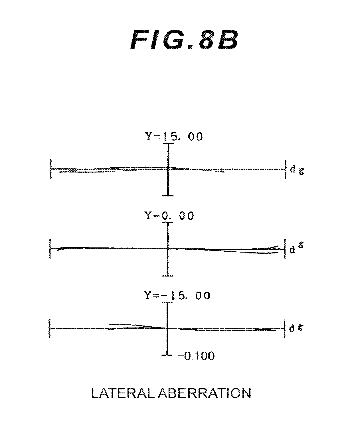
D00020

D00021

D00022

D00023

D00024

D00025
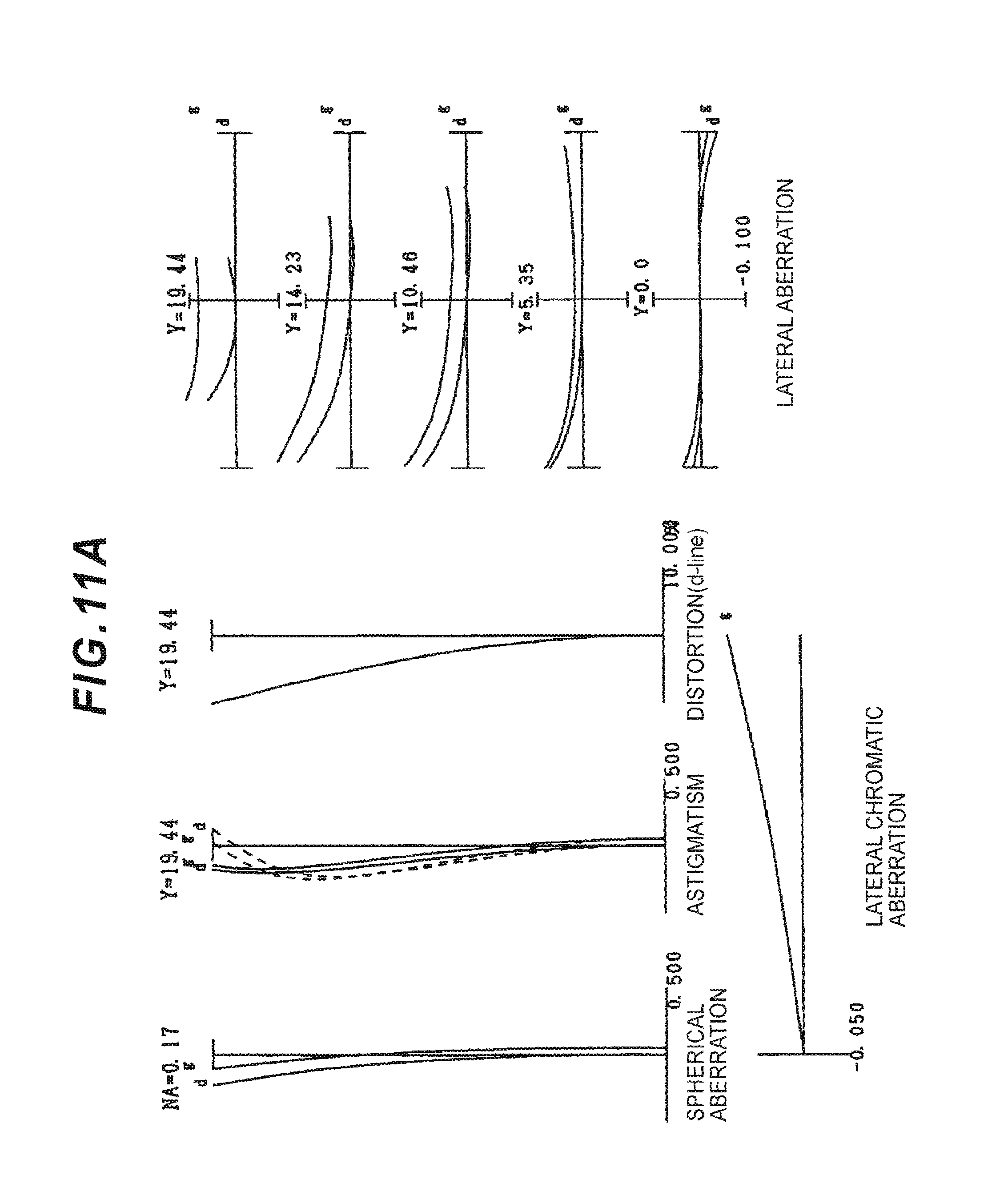
D00026

D00027

D00028

D00029

D00030

D00031

D00032
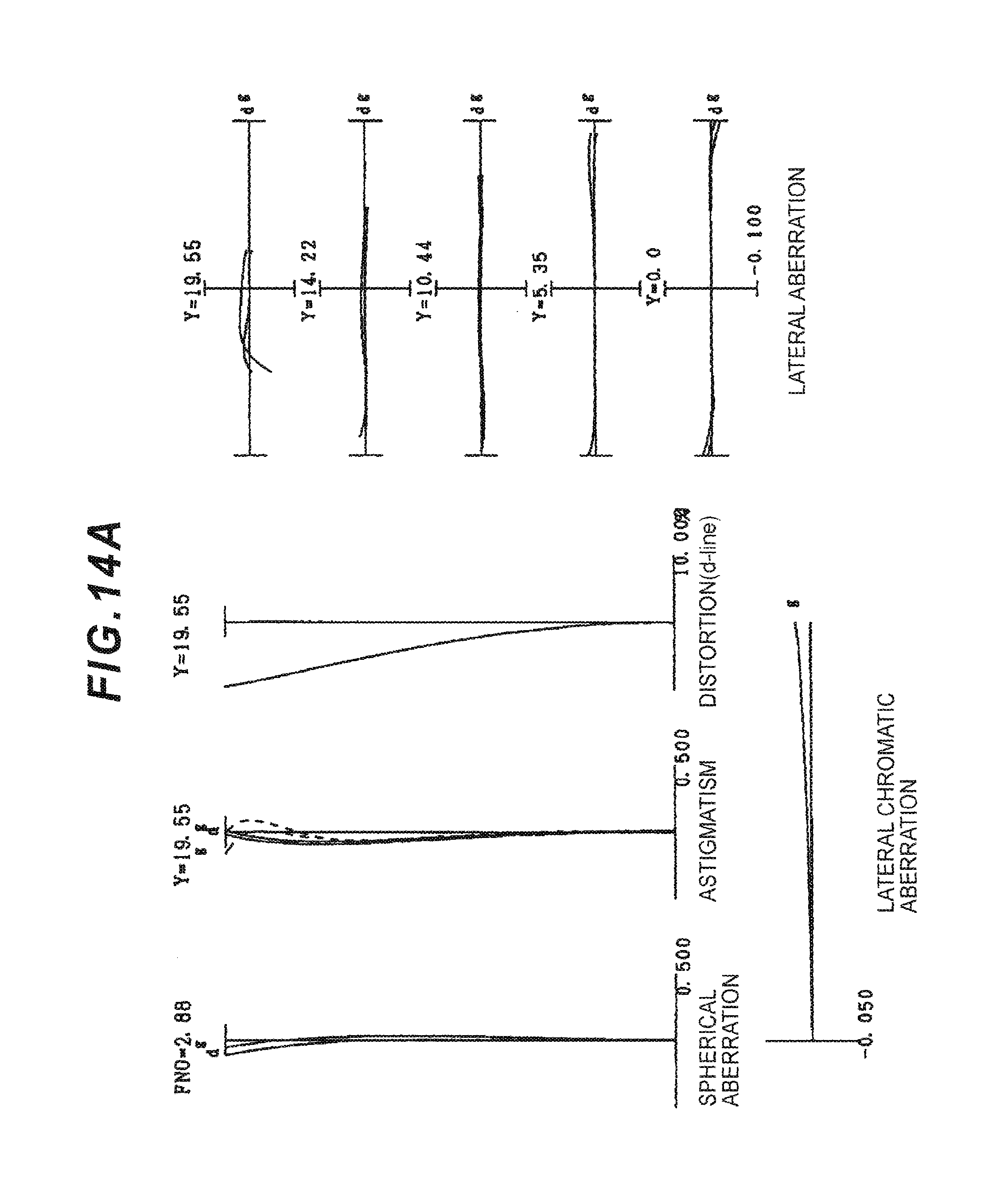
D00033

D00034

D00035

D00036

D00037

D00038

D00039

D00040

D00041

D00042

D00043

D00044

D00045

D00046

D00047

D00048

D00049

D00050

D00051

D00052

D00053

D00054

D00055

D00056

D00057

D00058

D00059

D00060

D00061

D00062

D00063

D00064

D00065

D00066

D00067

D00068

D00069

D00070

D00071

D00072

D00073

D00074

D00075

D00076

D00077

D00078

D00079

D00080

D00081
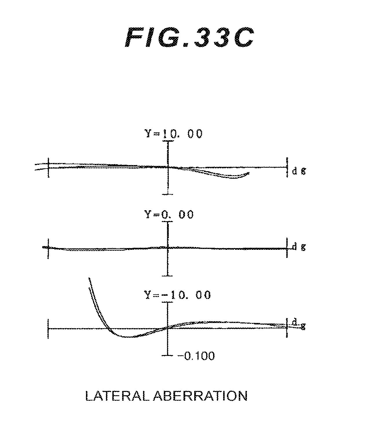
D00082

D00083

D00084

D00085

D00086

D00087

D00088

D00089

D00090
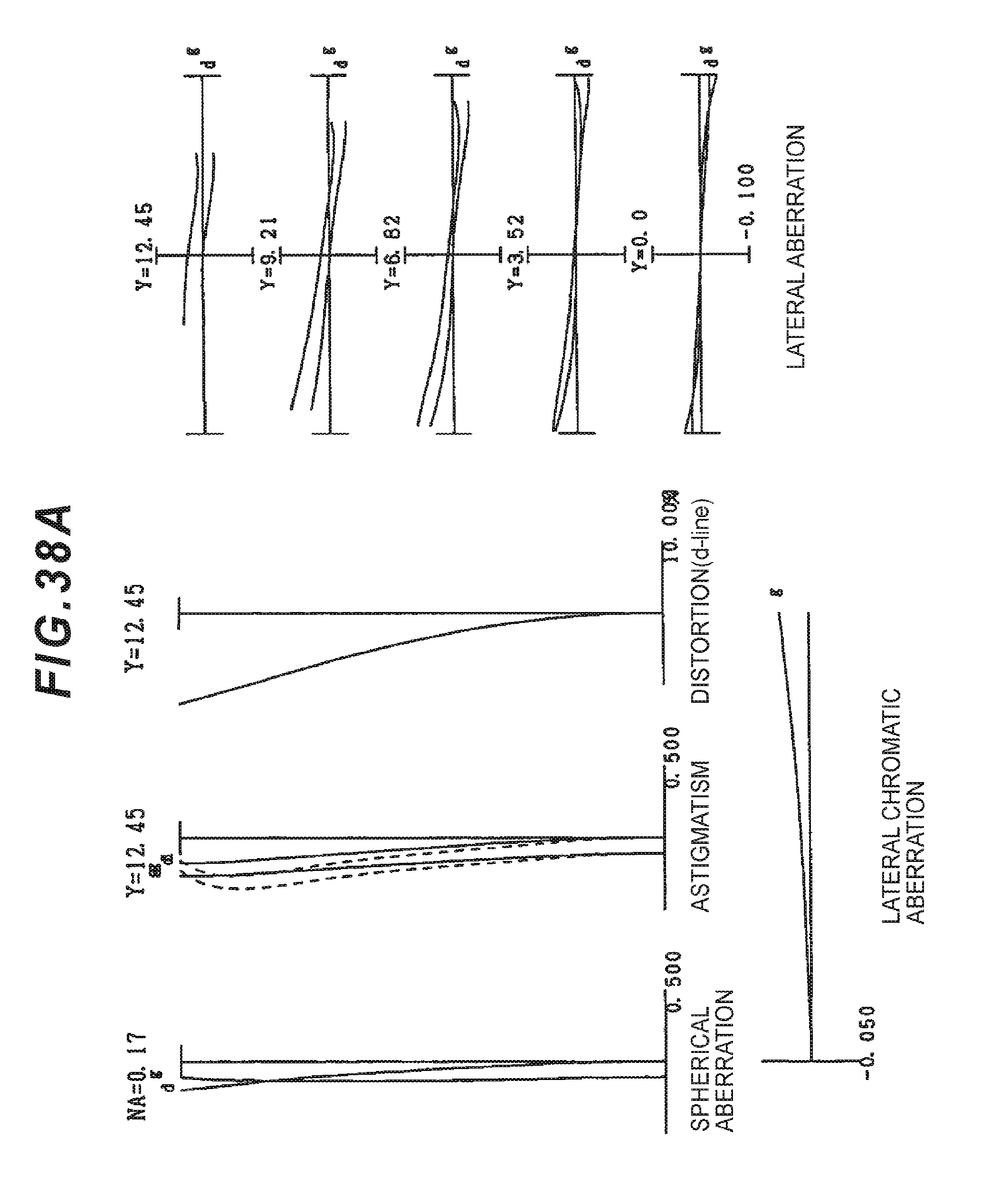
D00091

D00092

D00093

D00094

D00095

D00096

D00097

D00098
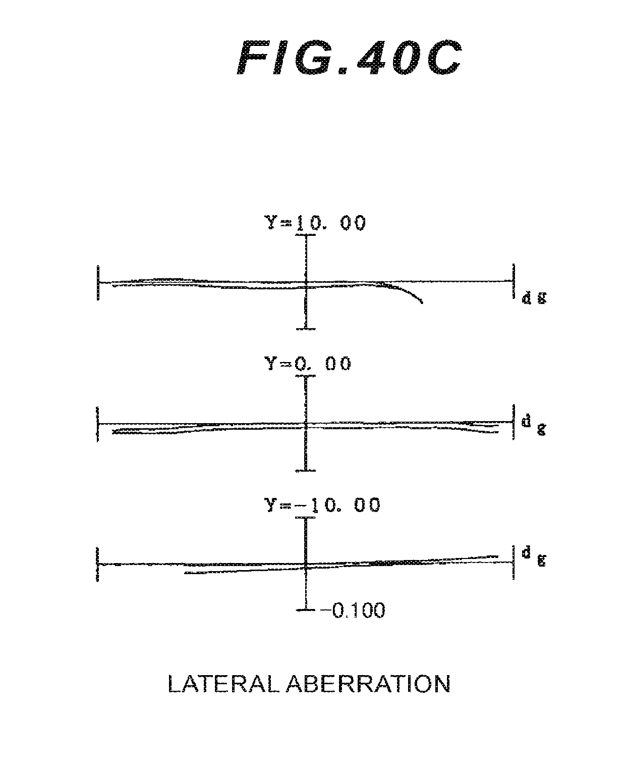
D00099

D00100

D00101

D00102

D00103

D00104

D00105

D00106

D00107

D00108

D00109

D00110

D00111

D00112
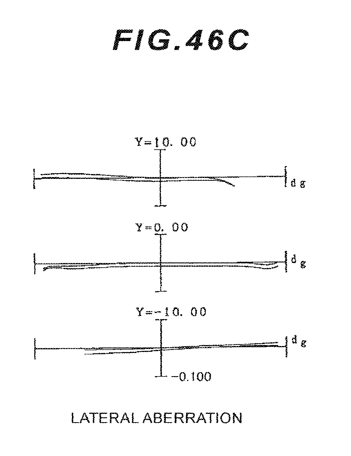
D00113

D00114

D00115

D00116

D00117

D00118

D00119

D00120

D00121

D00122

D00123

D00124

D00125

D00126

D00127

D00128

D00129

D00130

D00131

D00132

D00133

D00134

D00135

D00136

D00137

D00138
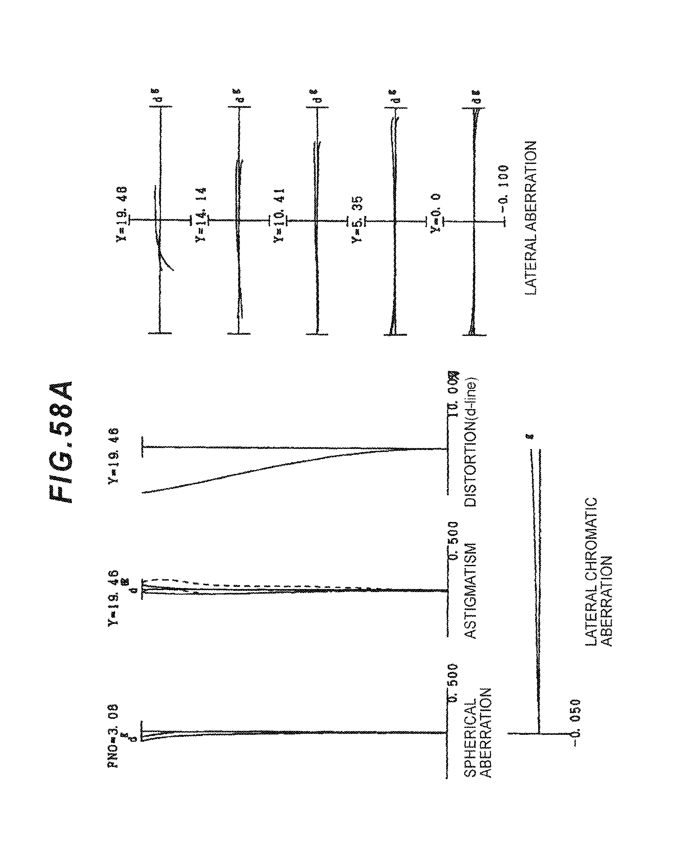
D00139

D00140
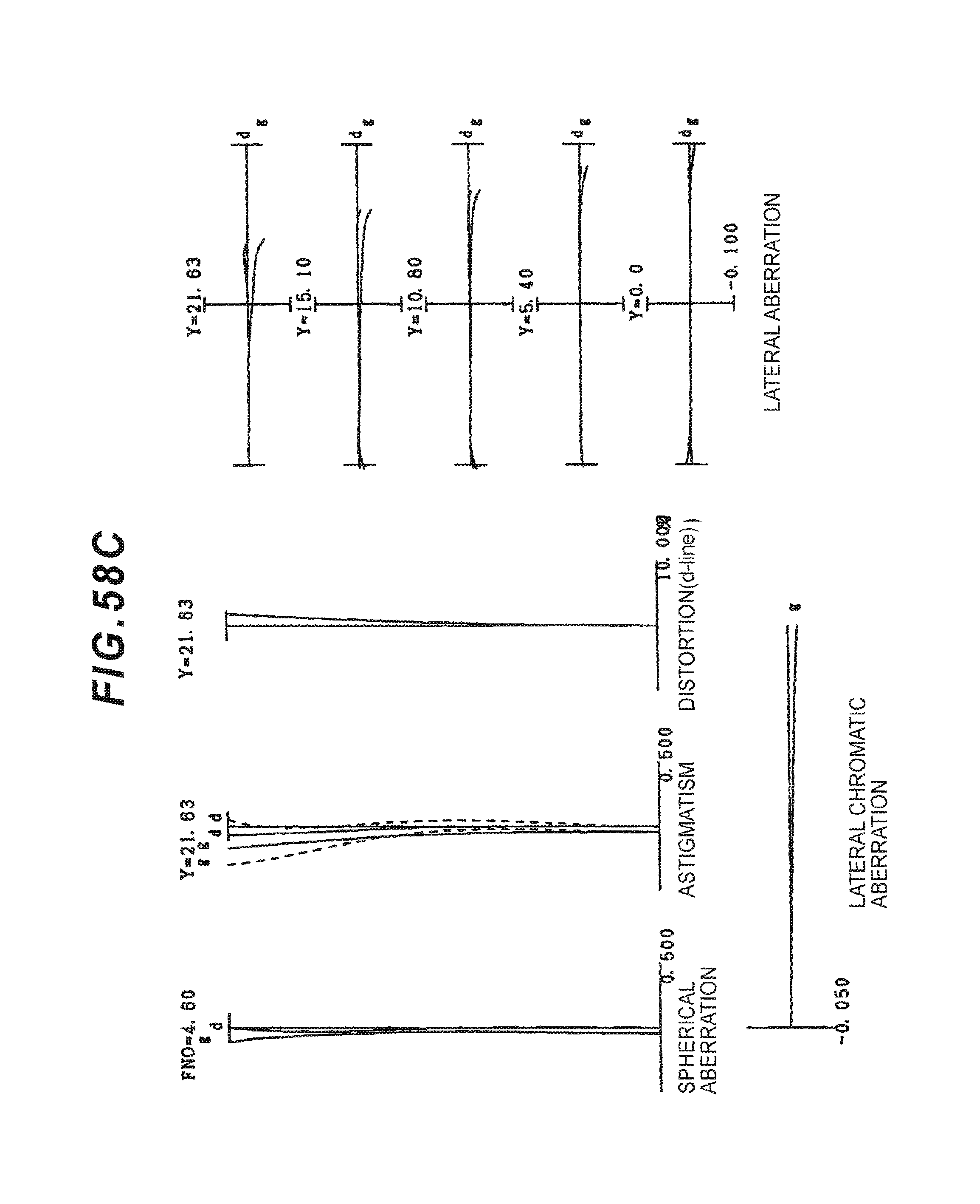
D00141

D00142

D00143

D00144

D00145

D00146

D00147
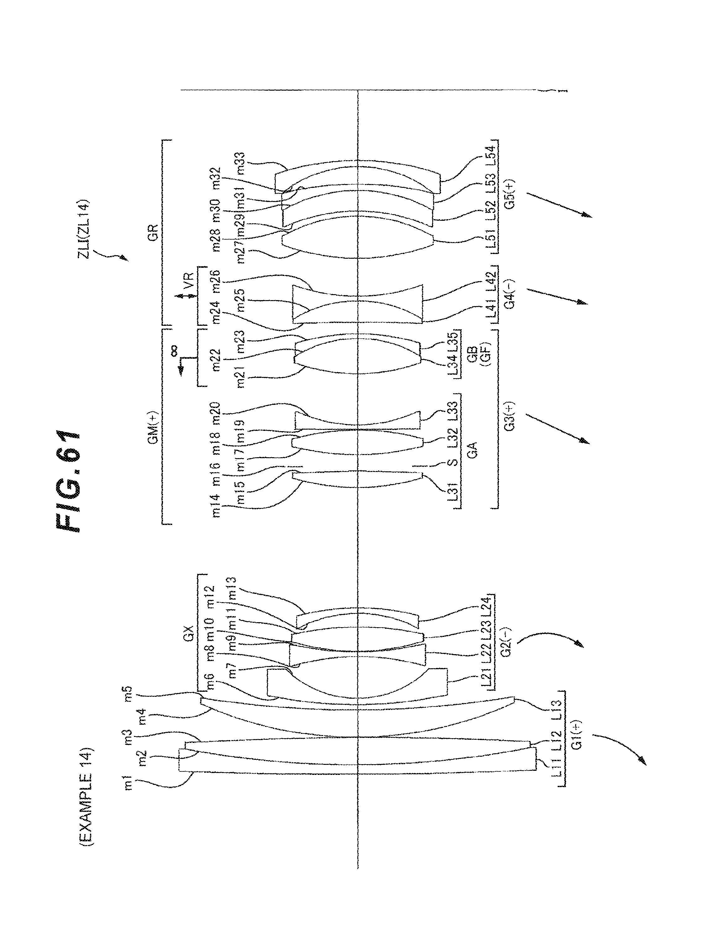
D00148

D00149

D00150

D00151

D00152

D00153

D00154

D00155

D00156

D00157

D00158

D00159

D00160

D00161

D00162

D00163

D00164

D00165

D00166

D00167
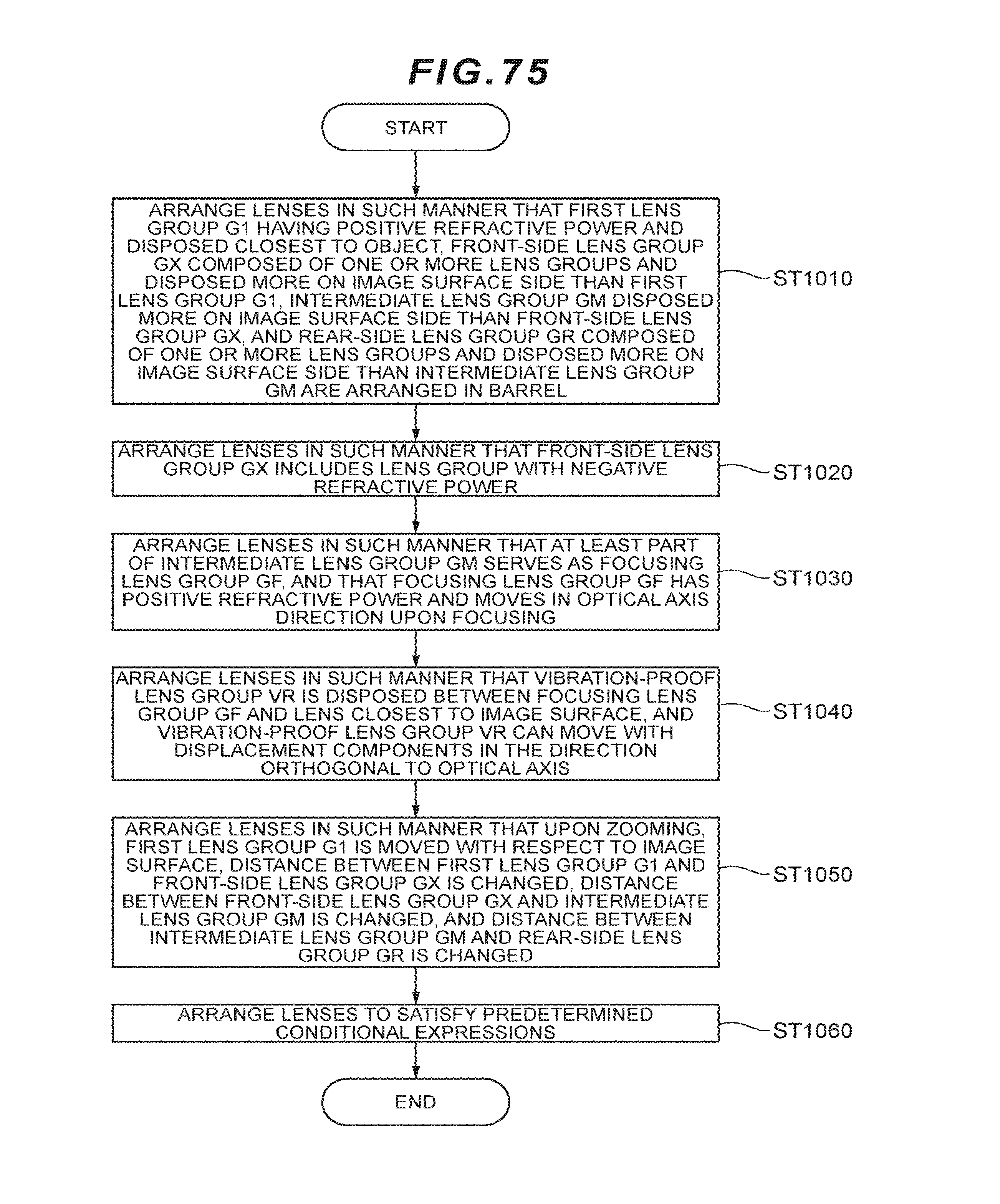
D00168

D00169

D00170

D00171

D00172

D00173

D00174

D00175

D00176
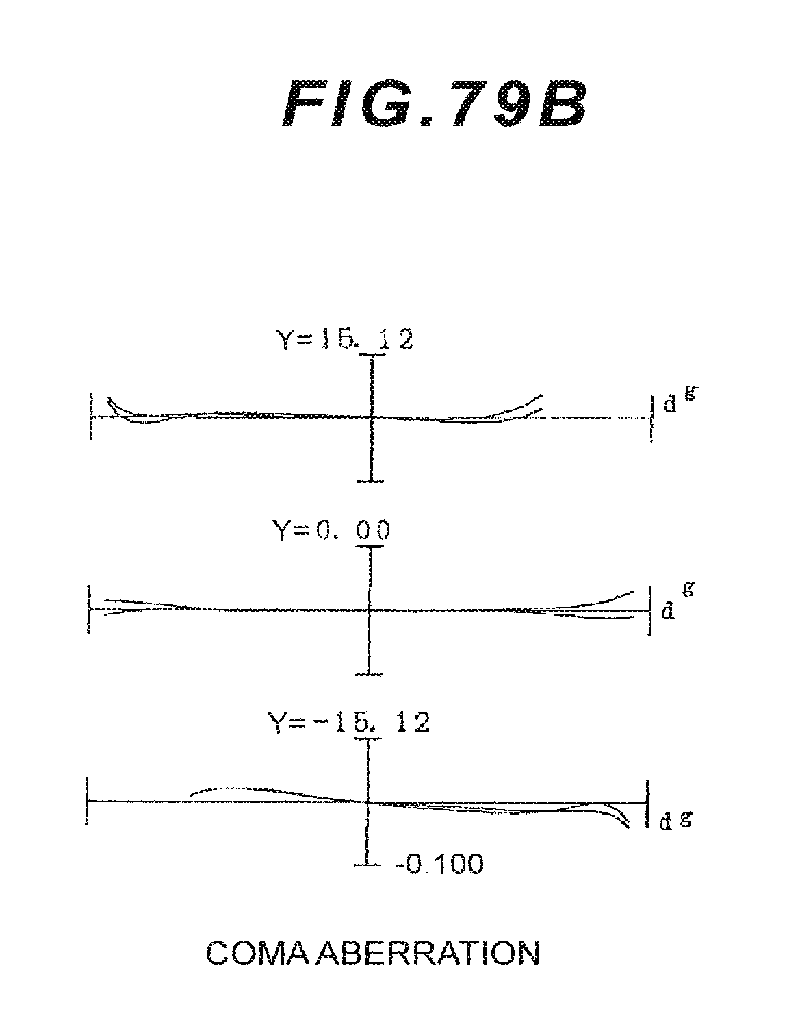
D00177

D00178

D00179

D00180

D00181

D00182

D00183

D00184

D00185

D00186

D00187

D00188

D00189

D00190

D00191

D00192

D00193

D00194

D00195

D00196

D00197

D00198

D00199

D00200

D00201

D00202

D00203

D00204

D00205

D00206

D00207

D00208

D00209

D00210

D00211

D00212

D00213

D00214
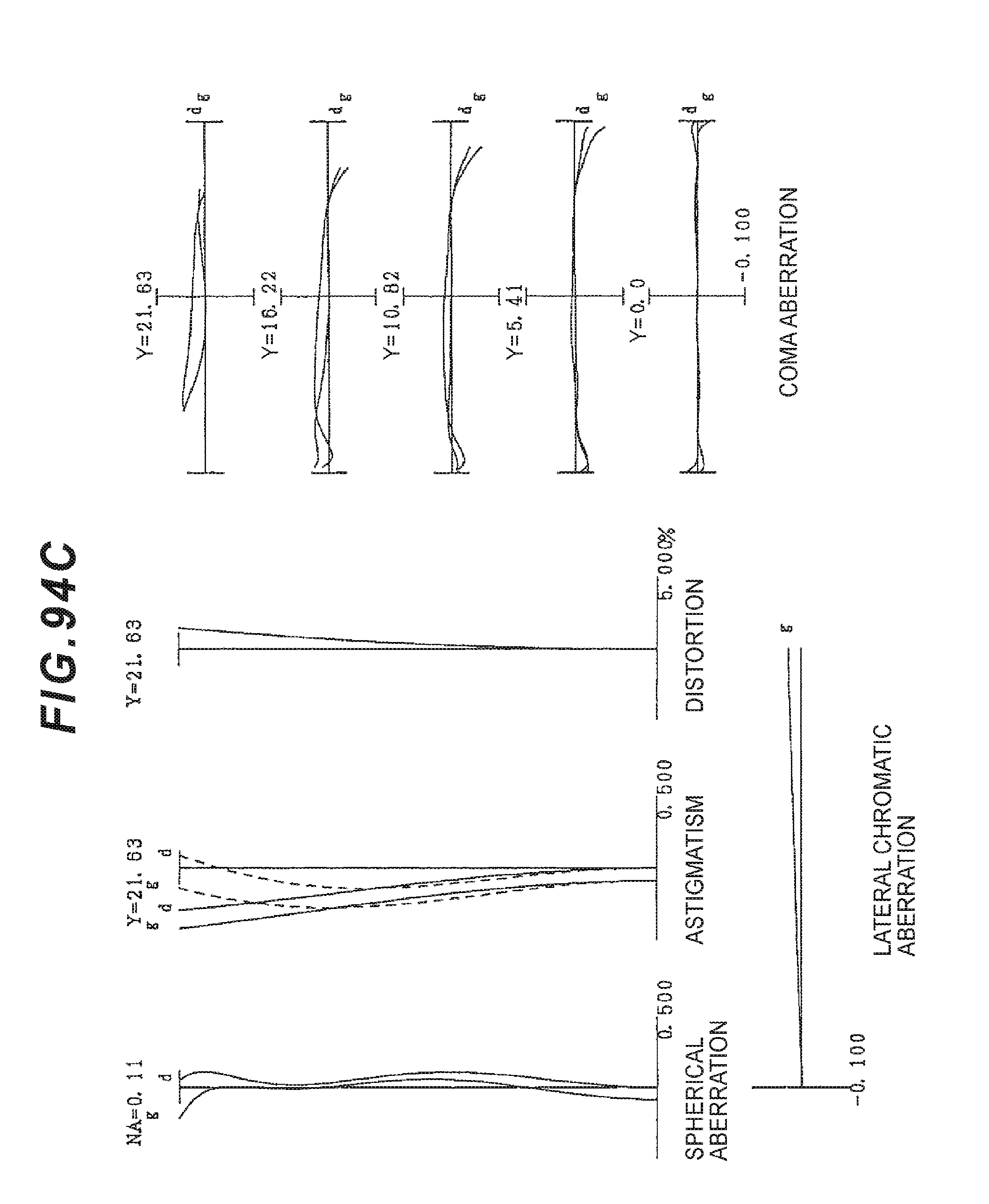
D00215

D00216

D00217

D00218

D00219

D00220

D00221

D00222

D00223

D00224

D00225

D00226

D00227

D00228

D00229

D00230

D00231

D00232

D00233

D00234

D00235

D00236

D00237

D00238

D00239

D00240

D00241

D00242

D00243
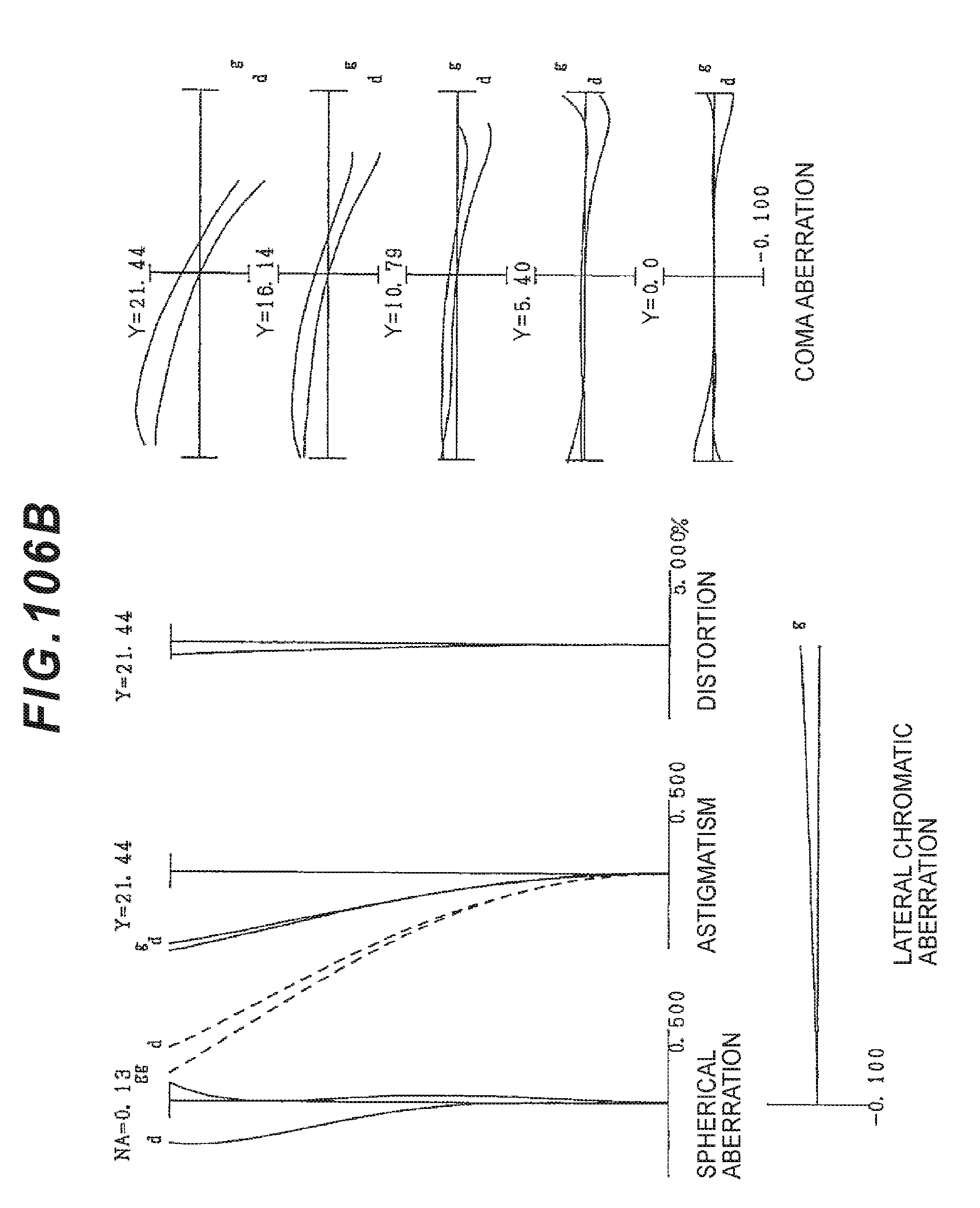
D00244

D00245

D00246

D00247

D00248

D00249

D00250

D00251

D00252

D00253

D00254

D00255

D00256

D00257

D00258

D00259

D00260

D00261

D00262

D00263

D00264

D00265

D00266

D00267

D00268

D00269

D00270

D00271

D00272

D00273

D00274

D00275

D00276

D00277
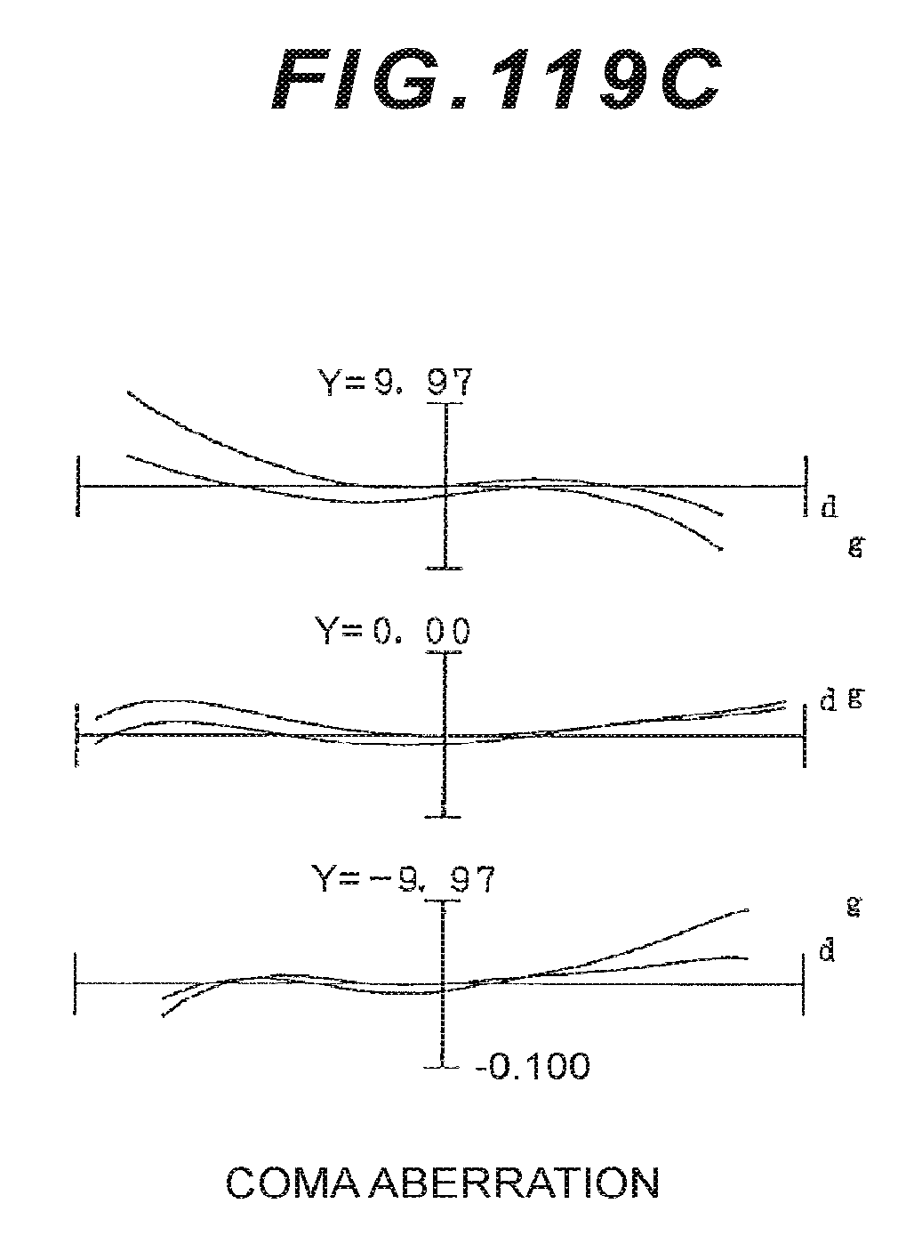
D00278

D00279

D00280

D00281
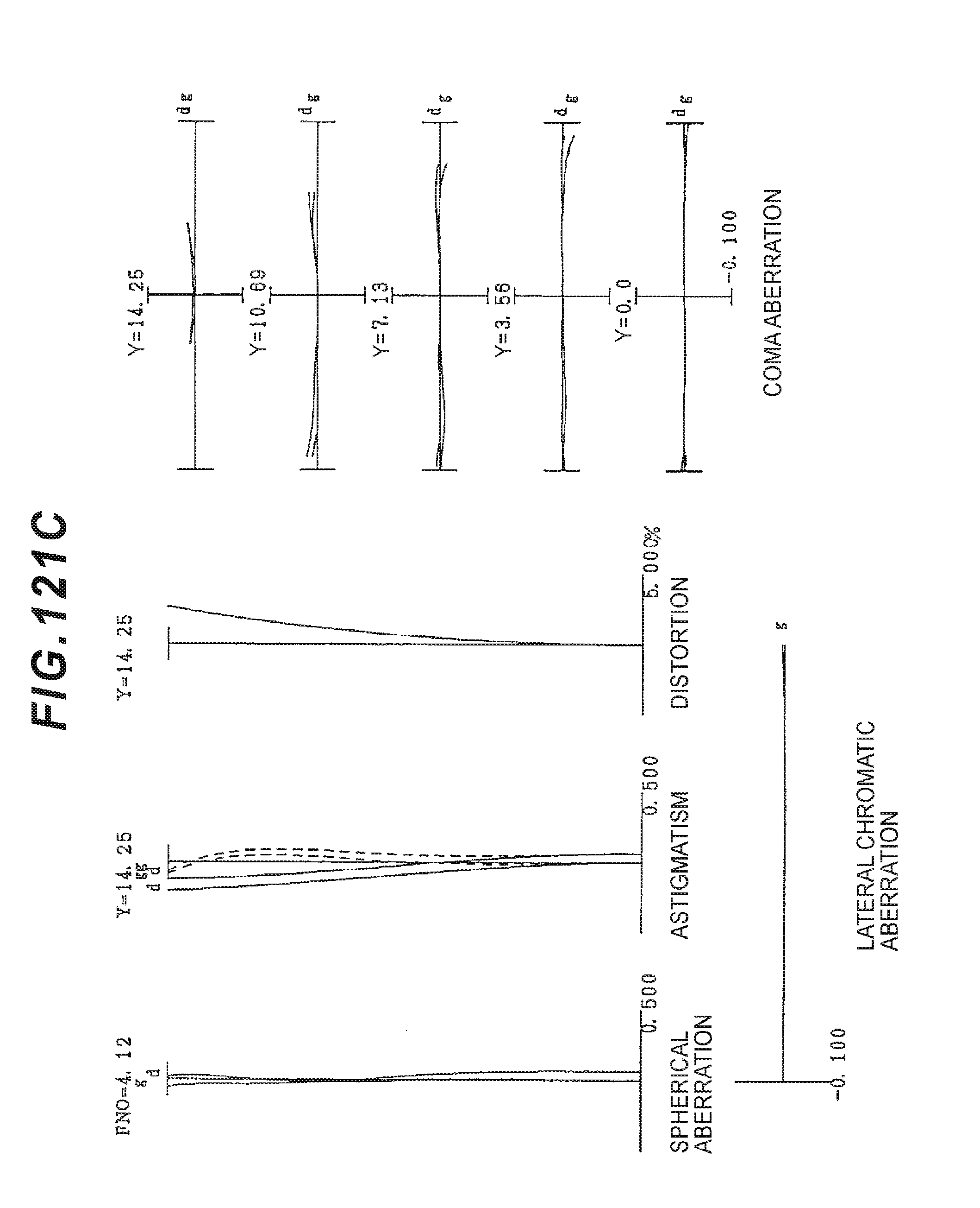
D00282

D00283

D00284

D00285

D00286

D00287

D00288

D00289

D00290

D00291

D00292

D00293

D00294

D00295

D00296

D00297

D00298

D00299

D00300

D00301

D00302

D00303

D00304

D00305

D00306

D00307

D00308

D00309

D00310

D00311

D00312

D00313

D00314

D00315

D00316

D00317

D00318

D00319

D00320

D00321

D00322

D00323

D00324

D00325

D00326

D00327

D00328

D00329

D00330

D00331

D00332

D00333

D00334

D00335

D00336

D00337

D00338

D00339

D00340

D00341

D00342

D00343

D00344

D00345

D00346

D00347

D00348

D00349

D00350

D00351

D00352

D00353

D00354

D00355

D00356

D00357

D00358
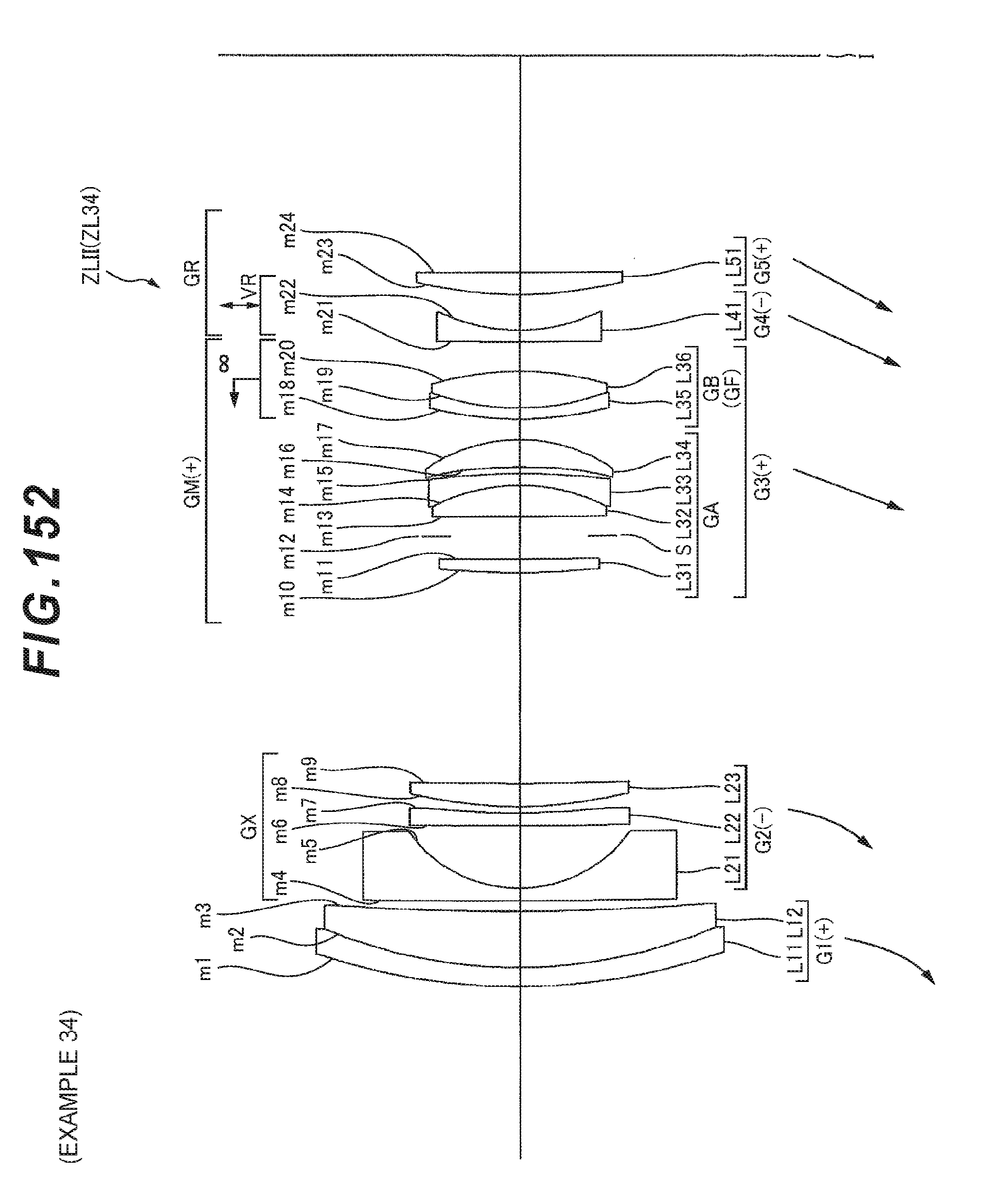
D00359

D00360

D00361

D00362

D00363

D00364

D00365

D00366

D00367

D00368

D00369

D00370

D00371

D00372

D00373

D00374

D00375

D00376
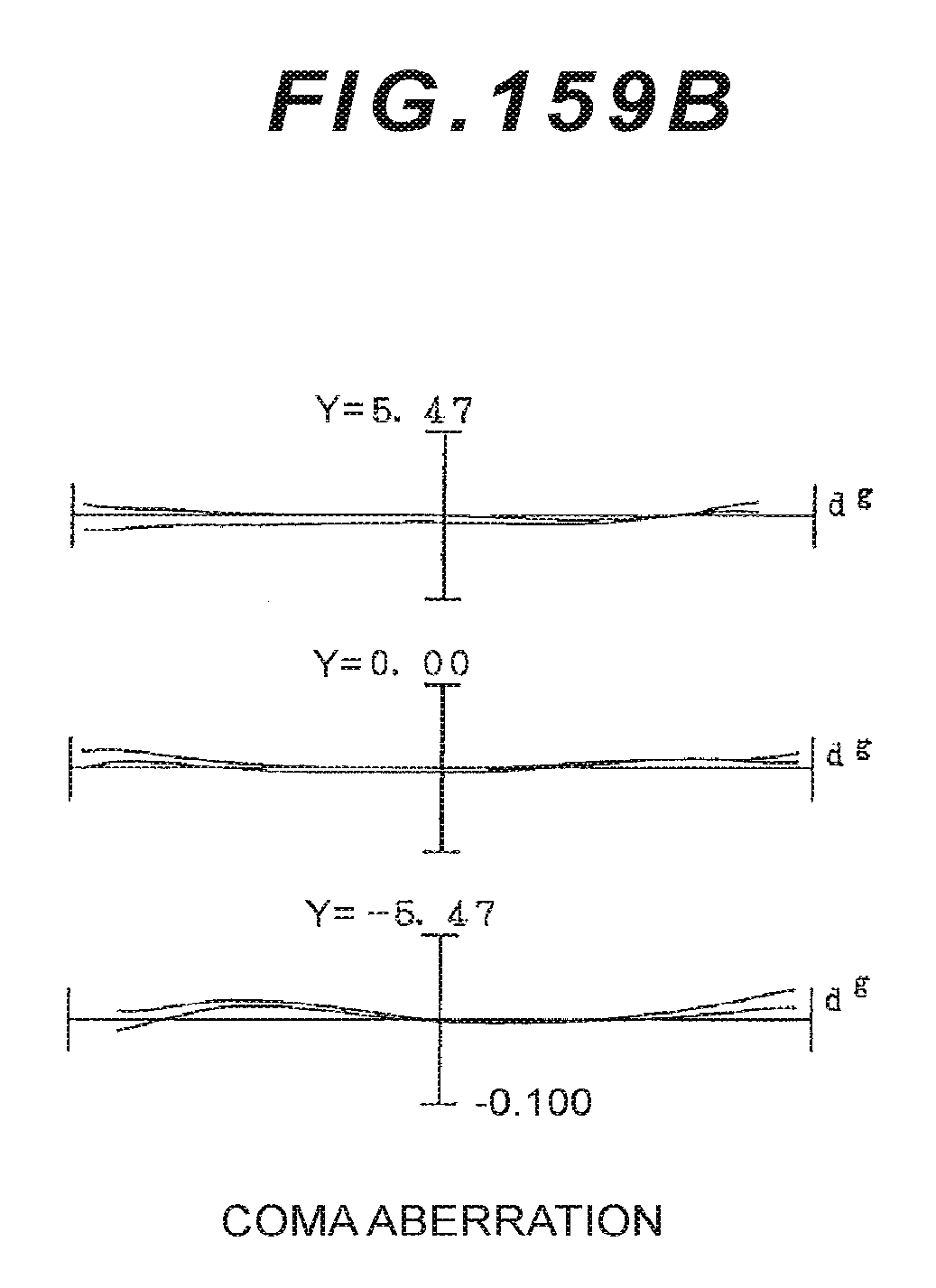
D00377
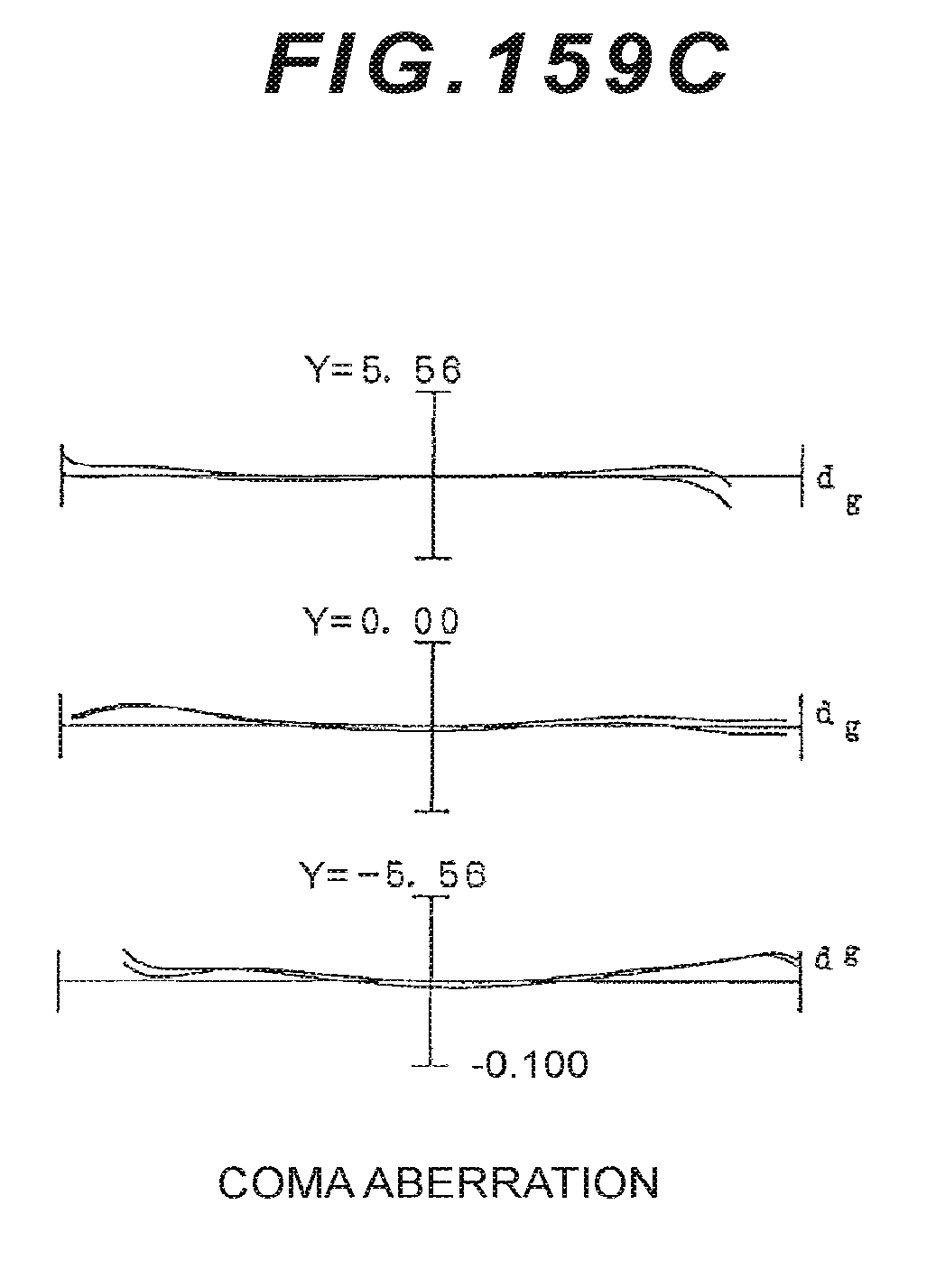
D00378
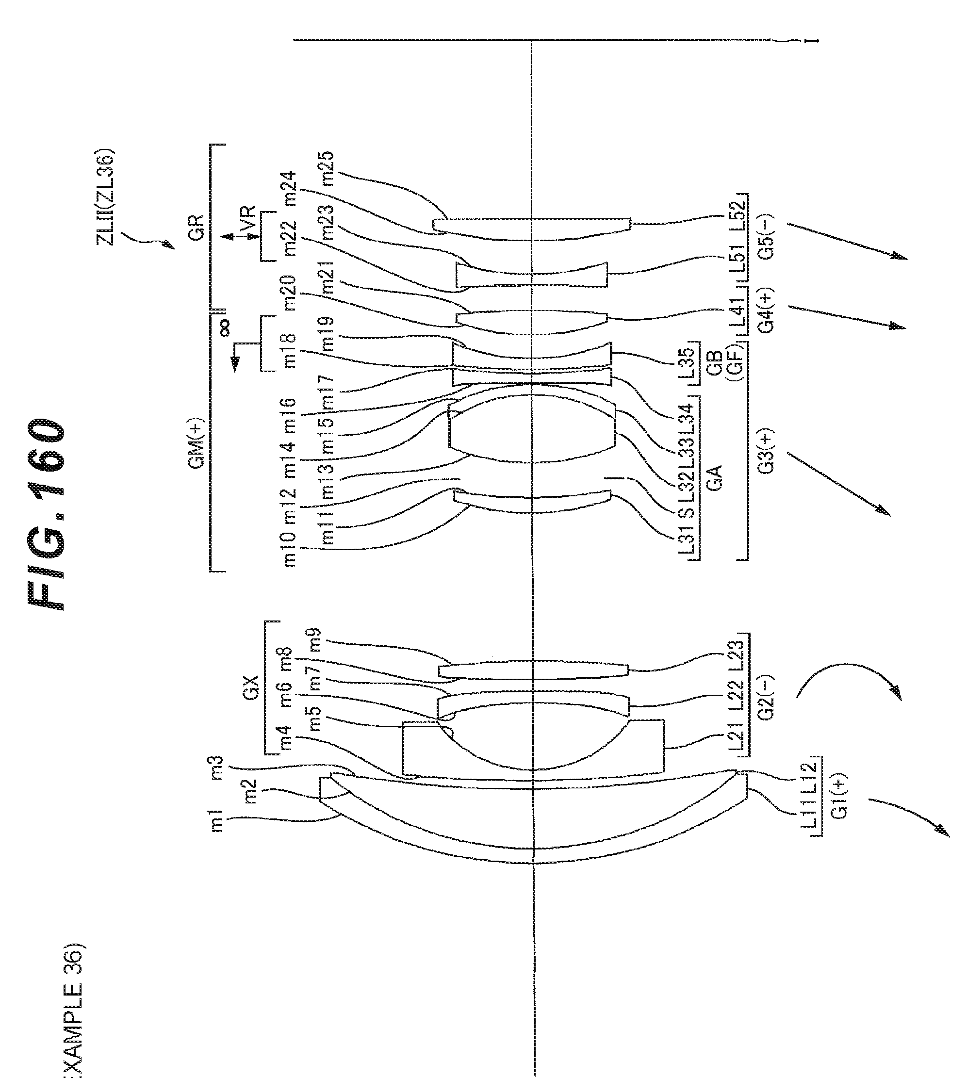
D00379

D00380

D00381

D00382
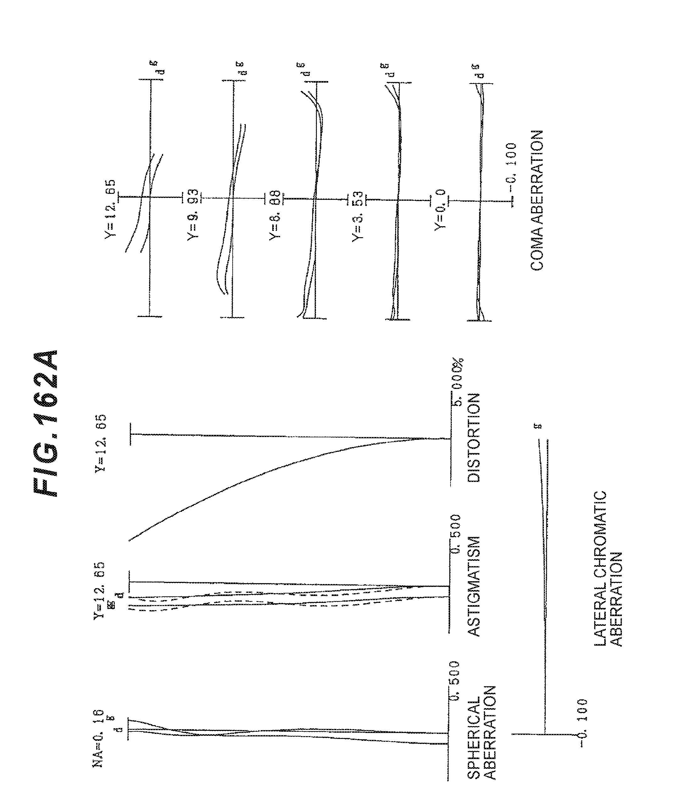
D00383

D00384

D00385

D00386

D00387

D00388

D00389

D00390
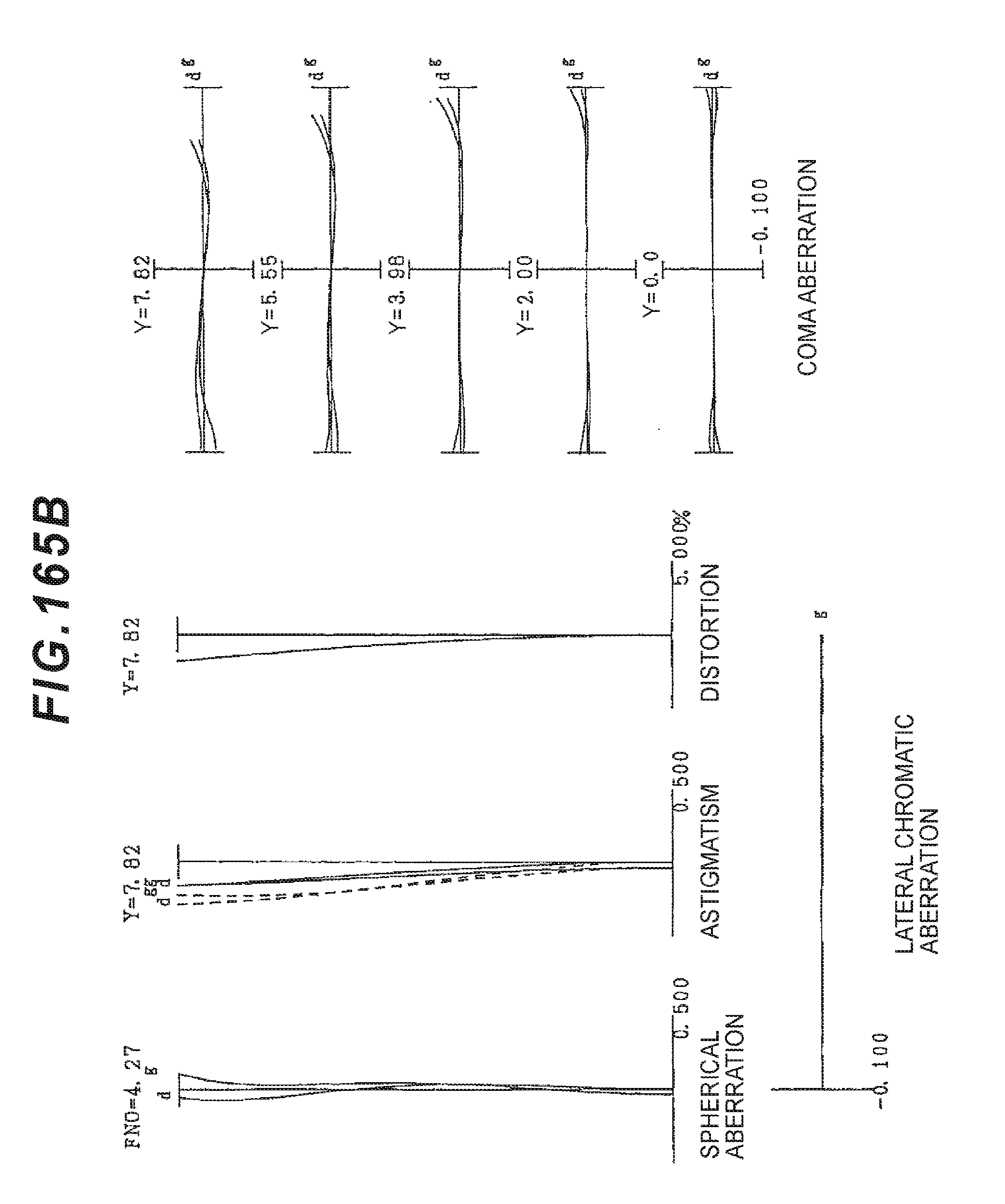
D00391

D00392

D00393

D00394

D00395
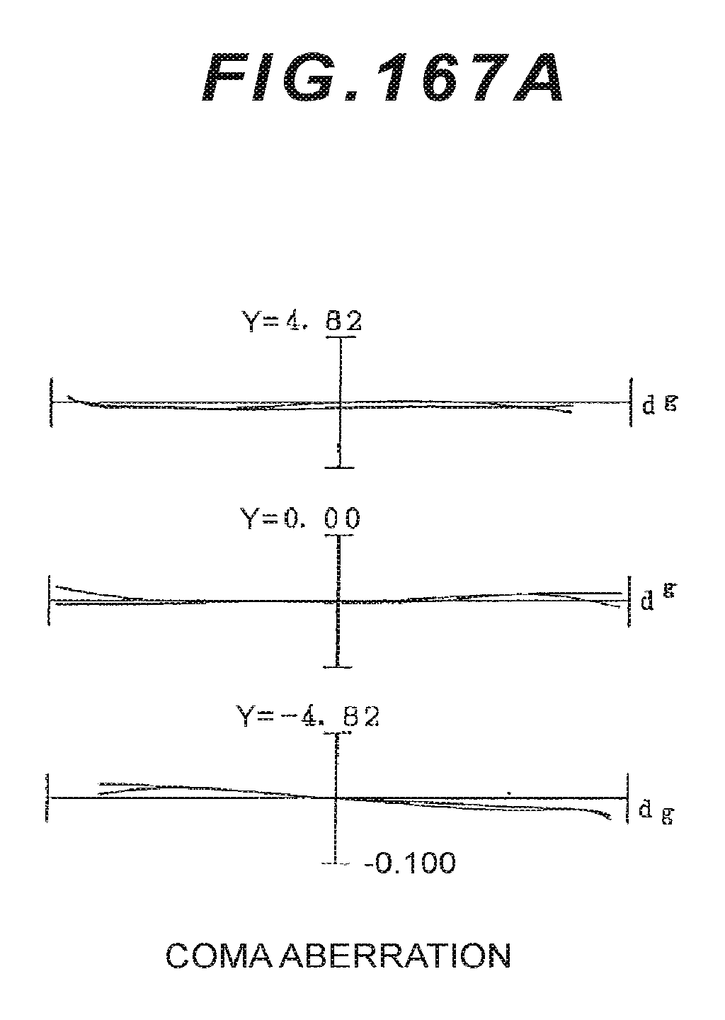
D00396

D00397

D00398

D00399

D00400

D00401

D00402

D00403

D00404

D00405

D00406

D00407

D00408

D00409

D00410

D00411

D00412

D00413

D00414

D00415

D00416

D00417

D00418

D00419

D00420

D00421

D00422

XML
uspto.report is an independent third-party trademark research tool that is not affiliated, endorsed, or sponsored by the United States Patent and Trademark Office (USPTO) or any other governmental organization. The information provided by uspto.report is based on publicly available data at the time of writing and is intended for informational purposes only.
While we strive to provide accurate and up-to-date information, we do not guarantee the accuracy, completeness, reliability, or suitability of the information displayed on this site. The use of this site is at your own risk. Any reliance you place on such information is therefore strictly at your own risk.
All official trademark data, including owner information, should be verified by visiting the official USPTO website at www.uspto.gov. This site is not intended to replace professional legal advice and should not be used as a substitute for consulting with a legal professional who is knowledgeable about trademark law.