Frame with connecting and positioning structure
Lai , et al. Feb
U.S. patent number 10,206,506 [Application Number 16/030,353] was granted by the patent office on 2019-02-19 for frame with connecting and positioning structure. This patent grant is currently assigned to SHENTER ENTERPRISE CO., LTD.. The grantee listed for this patent is Shenter Enterprise Co., Ltd.. Invention is credited to Kuo-Shu Huang, Ming-Hsiao Lai.
| United States Patent | 10,206,506 |
| Lai , et al. | February 19, 2019 |
Frame with connecting and positioning structure
Abstract
Disclosed is a frame with connecting and positioning structure. The frame has a plurality of cross bars and vertical bars which are correspondingly connected through the connecting and positioning structure. The connecting and positioning structure includes: a fixing seat fixed to the end of the cross bar; a fitting groove on the fixing seat; one end of the fitting groove is extended toward the bottom edge of the cross bar to form an opening end; an embedded block is provided for embedding in the retaining groove of the vertical bar; a plug-in column is connected with the embedded block; a fitting convex portion is connected to the other end of the plug-in column, and the fitting convex portion and the plug-in column are correspondingly inserted into the fitting groove; and a fixing member penetrates through the embedded block, the fitting convex portion, and the plug-in column to connect them together.
| Inventors: | Lai; Ming-Hsiao (Chang-Hua Hsien, TW), Huang; Kuo-Shu (Changhua, TW) | ||||||||||
|---|---|---|---|---|---|---|---|---|---|---|---|
| Applicant: |
|
||||||||||
| Assignee: | SHENTER ENTERPRISE CO., LTD.
(Chang-Hua Hsien, TW) |
||||||||||
| Family ID: | 65322579 | ||||||||||
| Appl. No.: | 16/030,353 | ||||||||||
| Filed: | July 9, 2018 |
| Current U.S. Class: | 1/1 |
| Current CPC Class: | A47B 96/1433 (20130101); A47B 95/00 (20130101); A47B 96/1441 (20130101); F16B 2012/443 (20130101); A47B 2220/0002 (20130101); A47B 47/0008 (20130101); A47B 2230/0025 (20130101); A47B 57/40 (20130101); A47B 47/00 (20130101) |
| Current International Class: | A47B 95/00 (20060101); A47B 96/14 (20060101); A47B 47/00 (20060101); A47B 57/40 (20060101) |
| Field of Search: | ;211/189,207,190,192,13.1,175,208,195,162,187 ;403/187,189,245,246,231 ;52/655.1,653.2,710 ;248/159,220.22,222.13,223.31,223.41,224.51,224.61 ;312/111 |
References Cited [Referenced By]
U.S. Patent Documents
| 685689 | October 1901 | Millikan |
| 867661 | October 1907 | Keating |
| 2805776 | September 1957 | Levitin |
| 2905232 | September 1959 | Umphred, Jr. |
| 3082711 | March 1963 | Vetere |
| 3106297 | October 1963 | Schroeder |
| 3261625 | July 1966 | Cripe |
| 3494478 | February 1970 | Link |
| 3498654 | March 1970 | Hector |
| 3540175 | November 1970 | Hawn |
| 3829999 | August 1974 | Bernstein |
| 3847489 | November 1974 | Van Riper |
| 3848844 | November 1974 | Barrett |
| 3879017 | April 1975 | Maxcy |
| 3901612 | August 1975 | Canin |
| 3945742 | March 1976 | Condevaux |
| 3969031 | July 1976 | Kroopp |
| 4021129 | May 1977 | Sykes |
| 4056196 | November 1977 | Brauning |
| 4212445 | July 1980 | Hagen |
| 4250679 | February 1981 | Burg |
| 4369953 | January 1983 | Greiner |
| 4488844 | December 1984 | Baubles |
| 4490064 | December 1984 | Ducharme |
| 4583359 | April 1986 | Staeger |
| 5154385 | October 1992 | Lindberg |
| 5192145 | March 1993 | Rixen |
| 5308037 | May 1994 | Gonzalez |
| 5407171 | April 1995 | Gonzalez |
| 5580181 | December 1996 | Nomura |
| 5695174 | December 1997 | Tsai |
| 5729948 | March 1998 | Levy |
| 5820289 | October 1998 | Kern |
| 5971365 | October 1999 | Pigott |
| 6029954 | February 2000 | Murdaca |
| 6032431 | March 2000 | Sugiyama |
| 6086300 | July 2000 | Frohlich |
| 6105794 | August 2000 | Bauer |
| 6141927 | November 2000 | Usui |
| 6223917 | May 2001 | Bruder |
| 6332657 | December 2001 | Fischer |
| 6378711 | April 2002 | Skulnik |
| 6402420 | June 2002 | Yang |
| 6481177 | November 2002 | Wood |
| 6547088 | April 2003 | Wang |
| 6682253 | January 2004 | Binna |
| 6712540 | March 2004 | Schmalzhofer |
| 6827320 | December 2004 | Yeh |
| 7004667 | February 2006 | Ludwig |
| 7037030 | May 2006 | McLemore |
| 7096637 | August 2006 | McMillan |
| 7762023 | July 2010 | Kasdorf |
| 7832570 | November 2010 | Reynolds |
| 8100600 | January 2012 | Blum |
| 8118181 | February 2012 | Shinozaki |
| 8348071 | January 2013 | Janlert |
| 8353500 | January 2013 | Walpole |
| 8376157 | February 2013 | Jarvis |
| 8397443 | March 2013 | Blom |
| 8627966 | January 2014 | Jarvis |
| 8689516 | April 2014 | Richardson |
| 8707653 | April 2014 | Calleja |
| 8827232 | September 2014 | Crowley |
| 8961060 | February 2015 | Oetlinger |
| 8973316 | March 2015 | Safford |
| 9010553 | April 2015 | Crowley |
| 9127504 | September 2015 | Sprague |
| 9167896 | October 2015 | Wu |
| 9212675 | December 2015 | Oetlinger |
| 9226575 | January 2016 | Crowley |
| 9782000 | October 2017 | Kahle |
| D829028 | September 2018 | Michell |
| 2002/0017839 | February 2002 | Wei |
| 2005/0265778 | December 2005 | Tzeng |
| 2006/0086684 | April 2006 | Wu |
| 2007/0062898 | March 2007 | Choi |
| 2010/0006526 | January 2010 | Konstant |
| 2010/0078614 | April 2010 | Graber |
| 2010/0084354 | April 2010 | Eustace |
| 2011/0073824 | March 2011 | Lappin |
| 2011/0241502 | October 2011 | Kao |
| 2011/0277417 | November 2011 | Welcel |
| 2012/0153657 | June 2012 | Kapoor |
| 2013/0221303 | August 2013 | Ash |
| 2013/0306808 | November 2013 | Huang |
| 2014/0048678 | February 2014 | Chen |
| 2014/0075980 | March 2014 | Villar |
| 2015/0272322 | October 2015 | Wu |
| 2015/0308095 | October 2015 | O'Neal |
| 2016/0017595 | January 2016 | Lee |
| 2017/0238710 | August 2017 | Tsai |
| 2018/0116400 | May 2018 | Lu |
Assistant Examiner: Barnett; Devin K
Attorney, Agent or Firm: Egbert Law Offices, PLLC
Claims
We claim:
1. A frame for storing objects comprising: a plurality of hollow horizontal cross bars; a plurality of vertical bars, wherein each vertical bar has a plurality of vertical retaining grooves defined therein; a plurality of fixing seats, each fixing seat having a sleeve, a plate body and a fitting groove, each sleeve having a distal end and an opposite proximal end, wherein each plate body is affixed to each distal end of each sleeve respectively, wherein each sleeve is inserted within and fixed to a corresponding end of a corresponding cross bar from said plurality of cross bars and each plate body covers each corresponding end of each corresponding cross bar respectively; wherein each fitting groove defines an opening at a bottom of each fixing seat, wherein each fitting groove of each fixing seat defines a first groove portion in each plate body and a second groove portion in each sleeve of each fixing seat, wherein each first groove portion is arch shaped, and wherein each second groove portion of each fitting groove has a larger width than a width of each first groove portion of each fitting groove respectively; a plurality of embedded blocks, wherein each embedded block is configured to be embedded within a corresponding retaining groove from said retaining grooves of a corresponding vertical bar from said plurality of vertical bars; a plurality of plug-in columns, wherein each plug-in column is connected with a corresponding embedded block from said plurality of embedded blocks, wherein a shrinkage convex portion protrudes from a first end of each plug-in column and engages each corresponding embedded block from said plurality of embedded blocks respectively; wherein a generally rectangular shaped fitting convex portion is connected to a second end of each plug-in column, wherein an arch shaped step portion is formed between each shrinkage convex portion and each fitting convex portion respectively; wherein each shrinkage convex portion is configured to be embedded into each corresponding retaining groove from said retaining grooves so that each plug-in column in unable to rotate relative to the corresponding vertical bars from said vertical bars; wherein a fastener is inserted with a fastener hole in each fitting convex portion and penetrates each plug-in column and each embedded block respectively to secure the embedded blocks, the plug-in columns, and the fitting convex portions to the vertical bars respectively; wherein each fitting convex portion is configured to be inserted within each second groove portion respectively and each plug-in column is configured to be inserted within each first groove portion respectively to secure the cross bars to the vertical bars respectively.
2. The frame defined in claim 1, wherein each plate body comprises a second shrinkage convex portion that is configured to be inserted within each retaining groove respectively, so that each fixing seat is prevented from being deflected relative to each vertical bar respectively.
3. The frame defined in claim 1, wherein a positioning protrusion is formed on an end face of each fitting convex portion, and a positioning groove is formed on an inner wall in each sleeve of each fitting groove; wherein each positioning protrusion is configured to be embedded in each positioning groove respectively to further secure each fitting convex portion within each fixing seat respectively.
4. The frame defined in claim 3, wherein a guide slope is formed on each inner wall of sleeve of each fixing seat.
5. The frame defined in claim 4, wherein a buckle part is protruded from a bottom edge of each sleeve; and each cross bar has a positioning hole for receiving each buckle part respectively.
Description
CROSS-REFERENCE TO RELATED U.S. APPLICATIONS
Not applicable.
STATEMENT REGARDING FEDERALLY SPONSORED RESEARCH OR DEVELOPMENT
Not applicable.
NAMES OF PARTIES TO A JOINT RESEARCH AGREEMENT
Not applicable.
REFERENCE TO AN APPENDIX SUBMITTED ON COMPACT DISC
Not applicable.
BACKGROUND OF THE INVENTION
1. Field of the Invention
The present invention relates generally to a frame, and more particularly to an innovative structure of a frame with connecting and positioning structure.
2. Description of Related Art Including Information Disclosed Under 37 CFR 1.97 and 37 CFR 1.98
Rack products are very common in daily life and are used for placing and storing various items such as daily necessities, books, tools, etc. to facilitate access and make the surrounding more tidy and beautiful.
At present, the rack products on the market are quite diverse, and are usually assembled from supporting columns, frames, and laminates. However, the actual use experience of such a rack structure type still reveals the following problems. The components of the conventional rack are usually fixed by screws, so that such a combination method not only leads to a more complex assembly/disassembly process, but also takes a lot of assembly time. Furthermore, if the components of the conventional rack are fixed by welding, then the supporting columns, frames, and laminates can no longer be adjusted and replaced. It is difficult to meet the different needs of consumers, and there is a need for improvement.
BRIEF SUMMARY OF THE INVENTION
Based on the foregoing objective, the present invention provides a frame with connecting and positioning structure. The frame has a plurality of cross bars and a plurality of vertical bars, and the cross bars and the vertical bars are correspondingly connected through the connecting and positioning structure. The connecting and positioning structure comprises: a fixing seat which is fixed to the end of the cross bar and has a plate body for covering the end face of the cross bar; a fitting groove which is provided on the fixing seat and its plate body; one end of the fitting groove is extended toward the bottom edge of the cross bar to form an opening end, and the fitting groove is in an inner-wide and outer-narrow structure type along the axial direction of the cross bar; an embedded block provided for embedding in the retaining groove of the vertical bar; a plug-in column which is connected with the embedded block, and a shrinkage convex portion is extended at an end of the plug-in column connected to the embedded block; a step portion is formed between the shrinkage convex portion and the plug-in column; the shrinkage convex portion is used to embed into the retaining groove, so that the plug-in column in unable to rotate relative to the vertical bar; further, the step portion rests on the wall of the opening of the retaining groove, so that the step portion and the embedded block are retained to the wall of the opening of the retaining groove; a fitting convex portion is connected to the other end of the plug-in column, and the fitting convex portion and the plug-in column coincide with the fitting groove, showing an inner-wide and outer-narrow structure pattern, for inserting into the fitting groove in a tight fit state; and a fixing member penetrating the embedded block, the fitting convex portion, and the plug-in column to connect them together.
With this innovative and unique design, in comparison with the prior art, due to the structural design of the abutment surface of the plug-in column corresponding to the closed end of the fitting groove, insertion of the fitting convex portion into the fitting groove is achieved to realize the oriented combination fool proof effect. In addition, the cross bars and the vertical bars are connected through the connecting and positioning structure without requiring any hand tools. Thus, assembly and disassembly can be easily and quickly achieved to attain the objective of saving time and convenience, which is particularly practical and progressive.
BRIEF DESCRIPTION OF THE SEVERAL VIEWS OF THE DRAWINGS
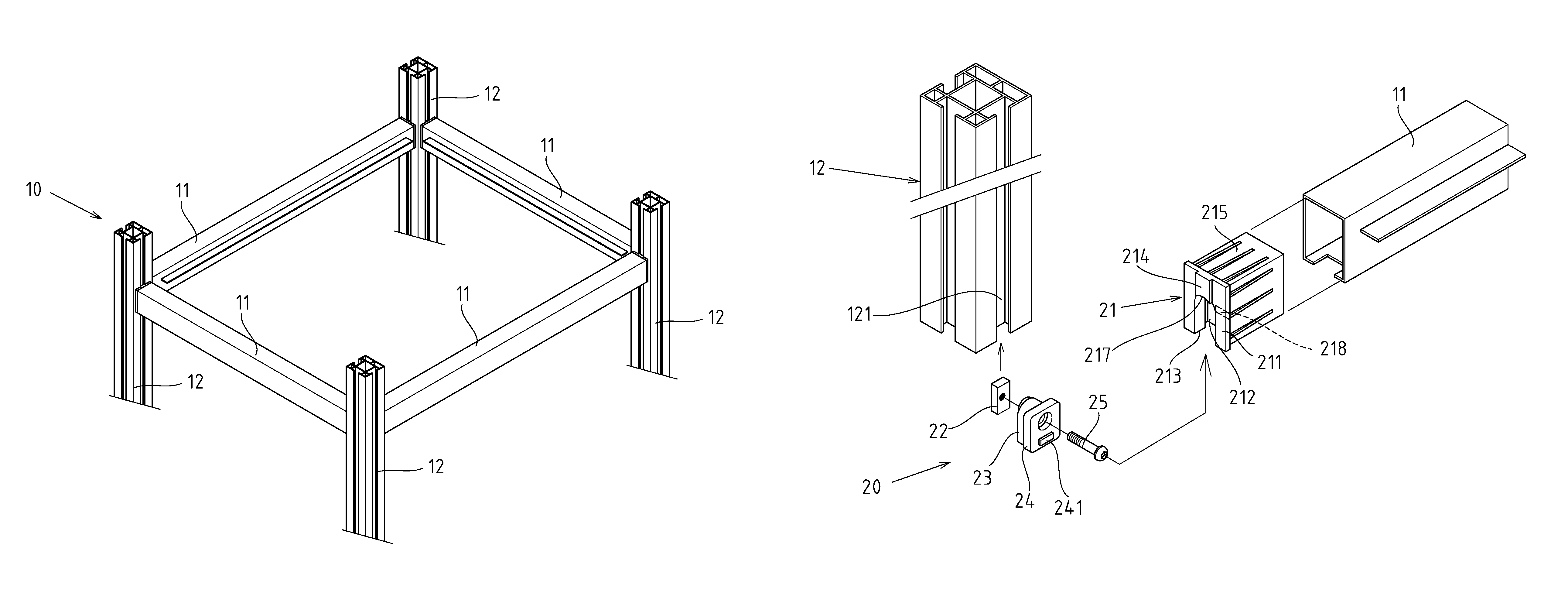
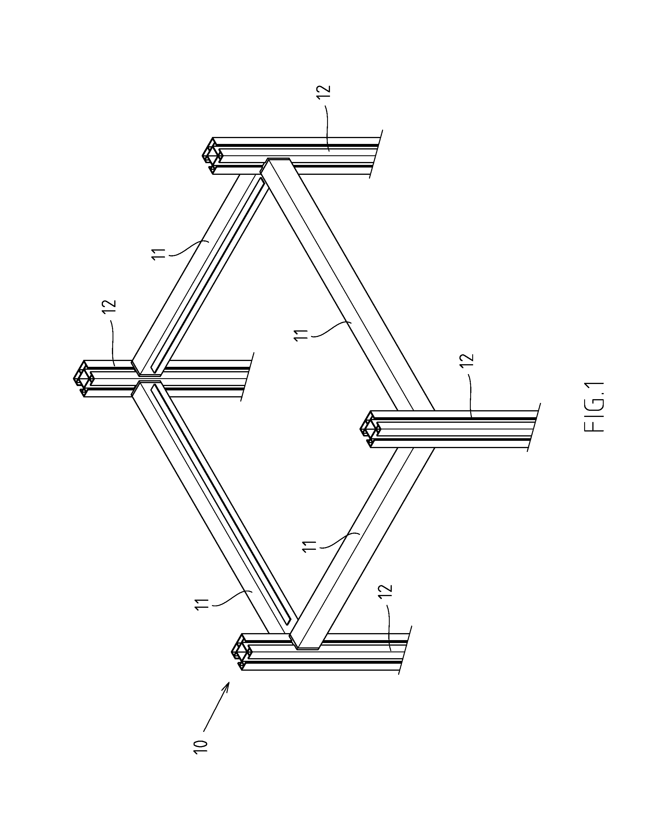
FIG. 1 is a three-dimensional assembly diagram of the first embodiment of the present invention.
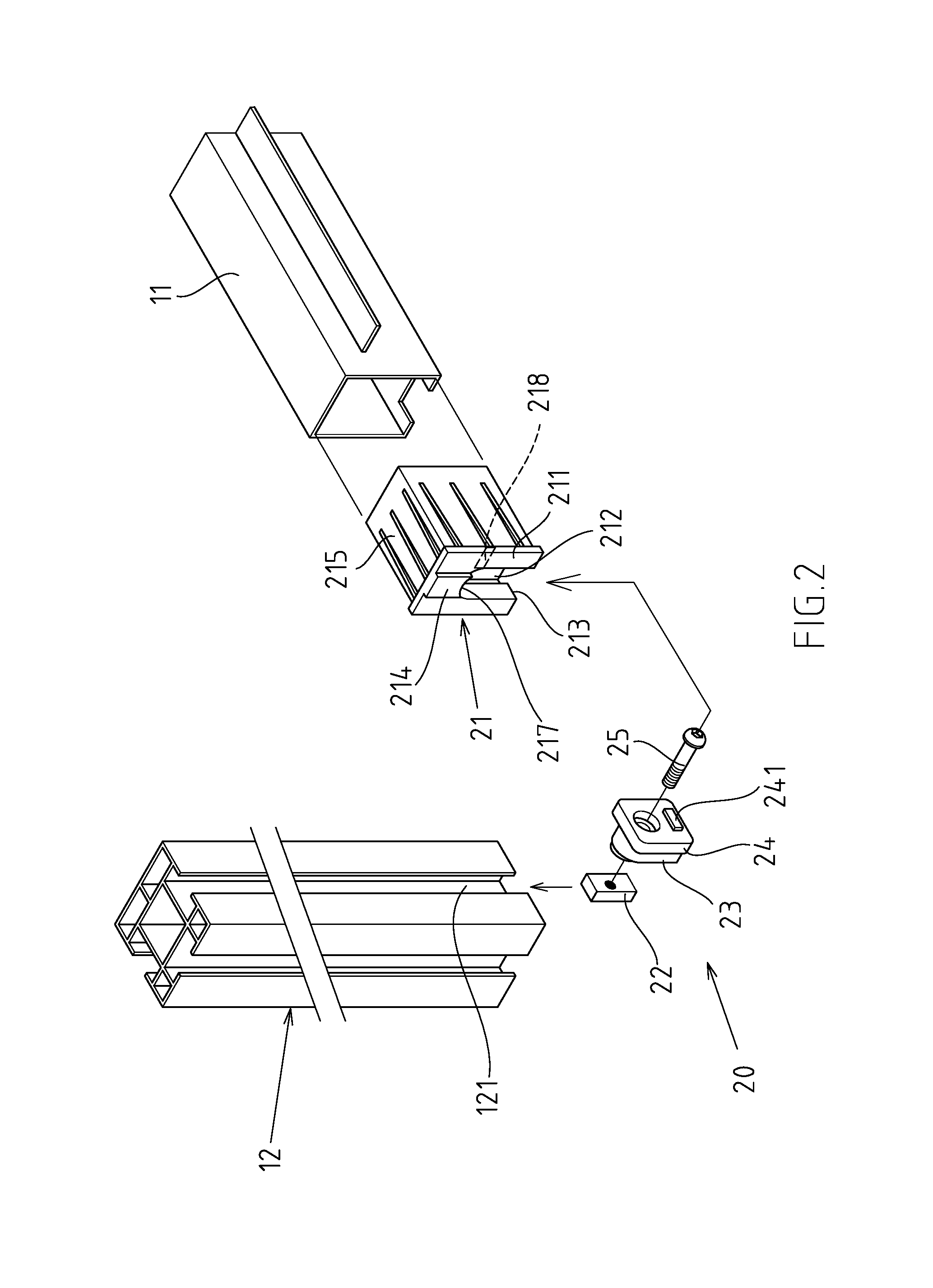
FIG. 2 is a partial exploded diagram of FIG. 1.
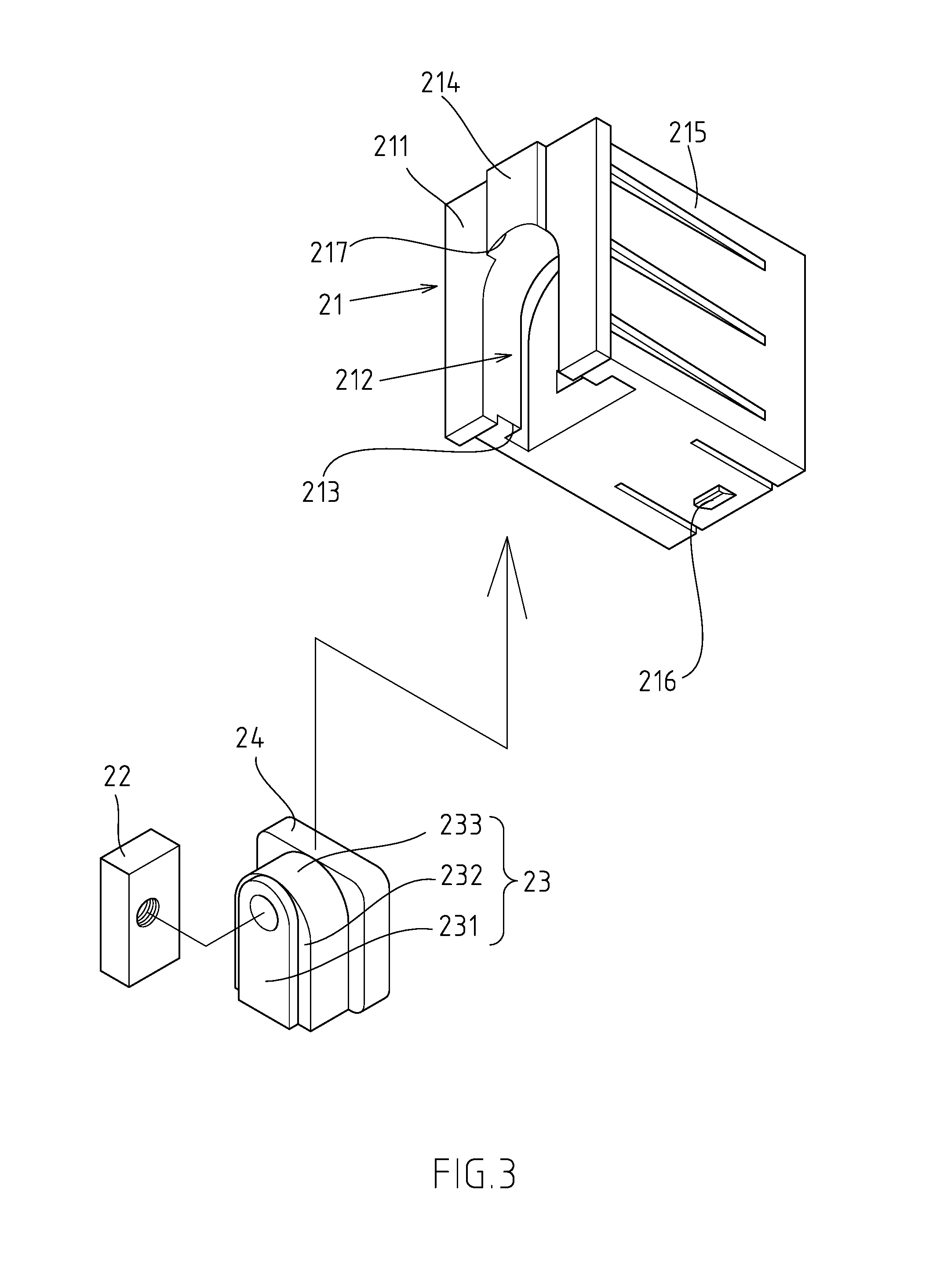
FIG. 3 shows a schematic diagram of FIG. 2 from another angle of view.
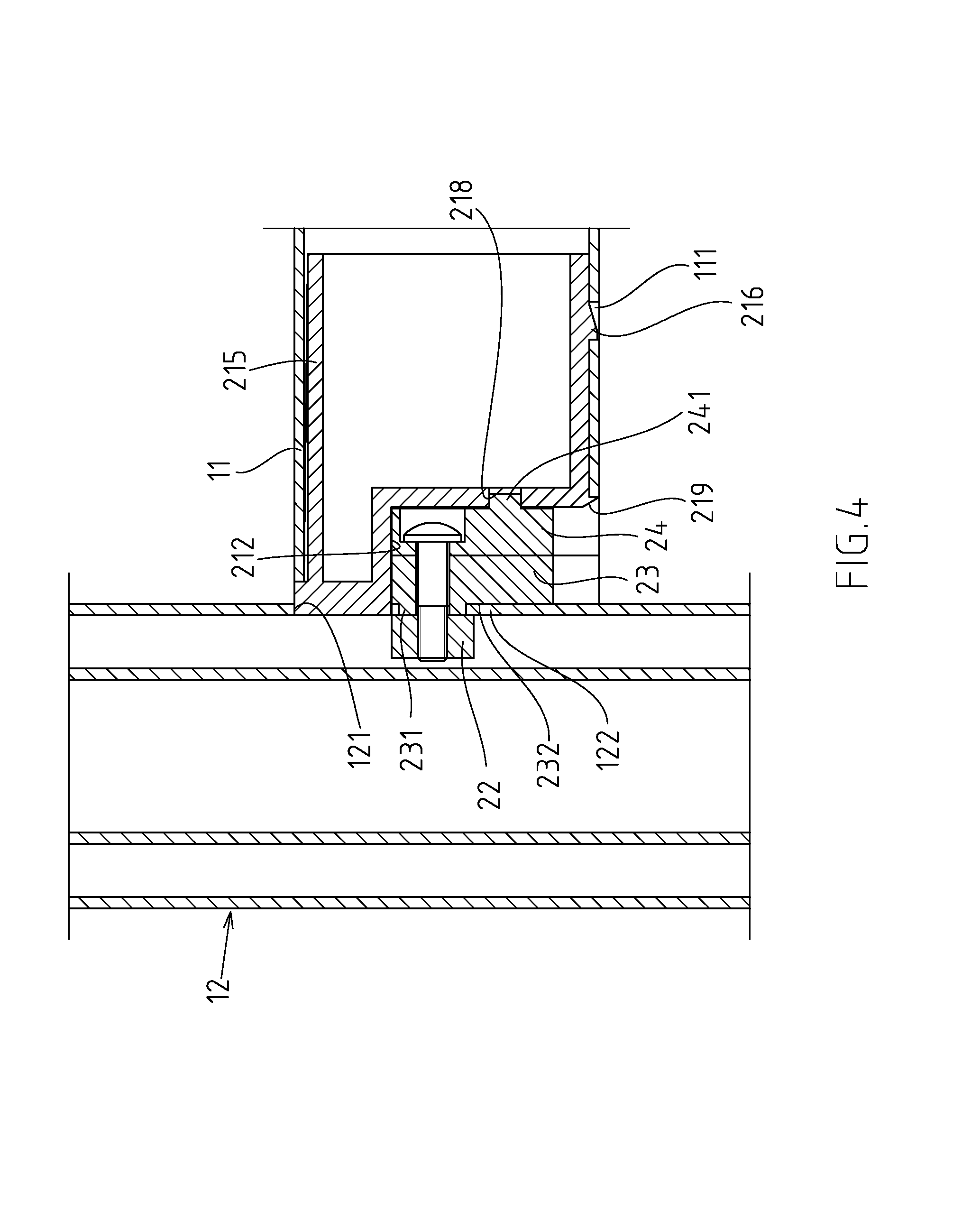
FIG. 4 is a partial assembly sectional view of FIG. 1.
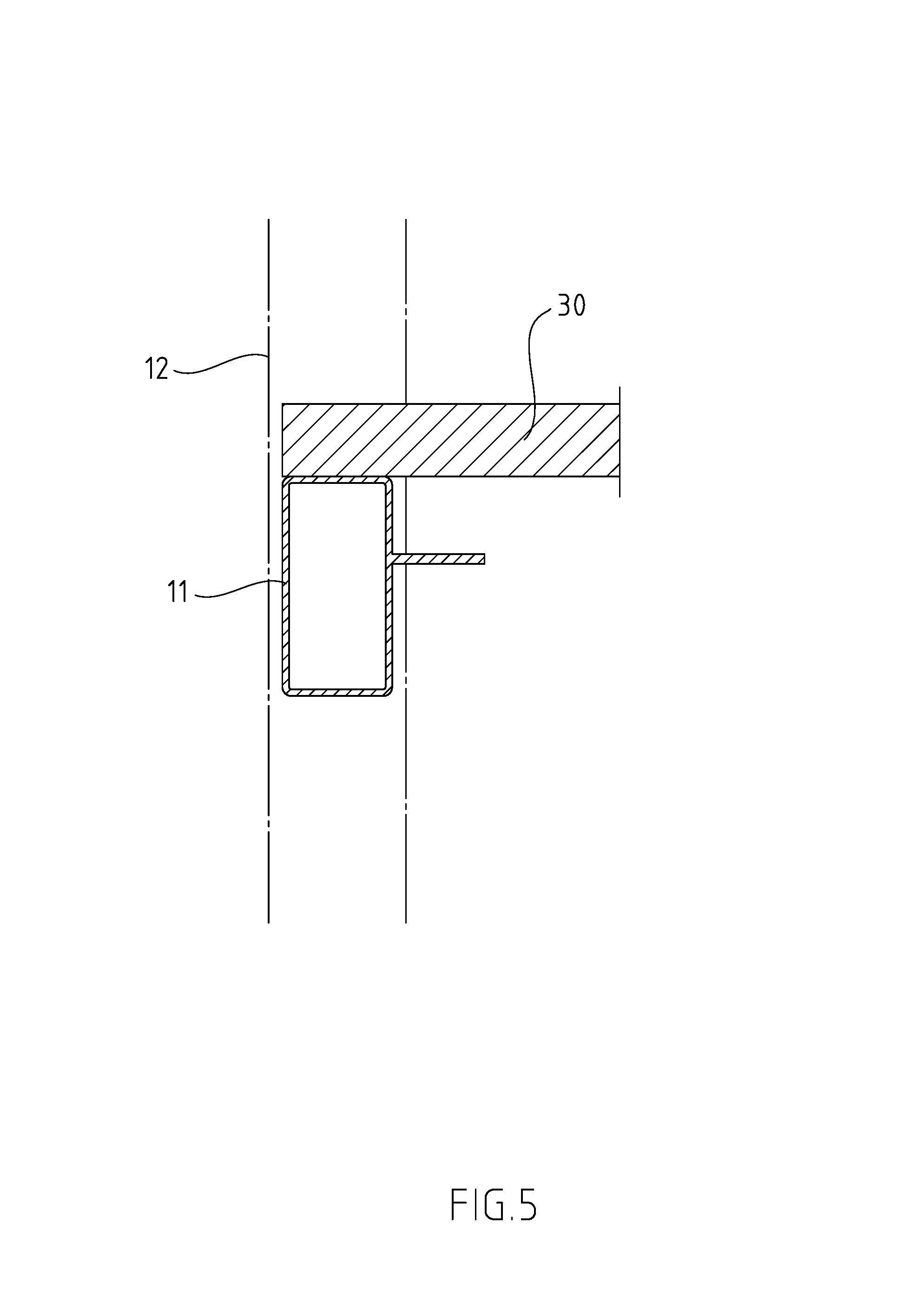
FIG. 5 is the first embodiment of placing bearing plate in FIG. 1.
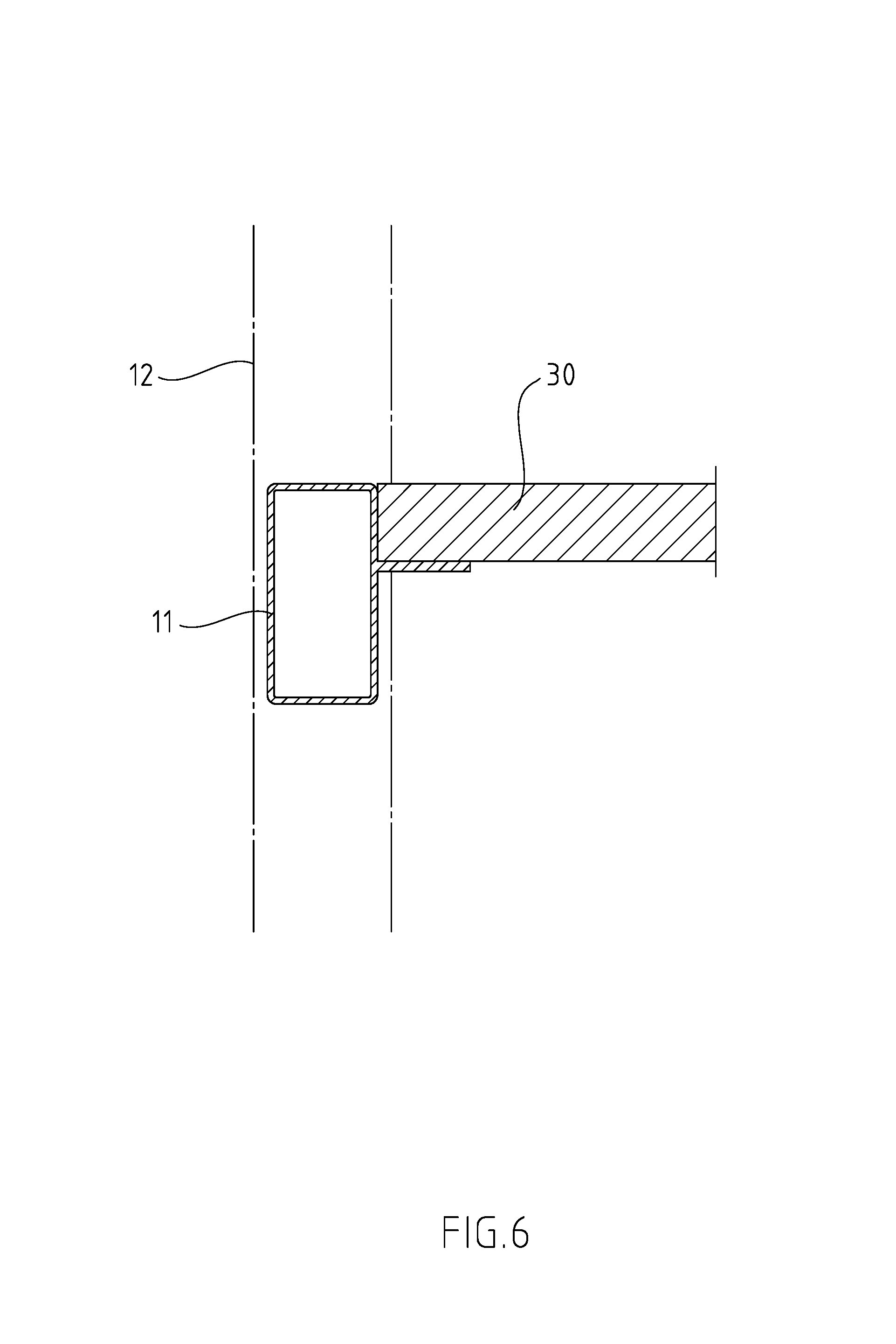
FIG. 6 is the second embodiment of placing bearing plate in FIG. 2.
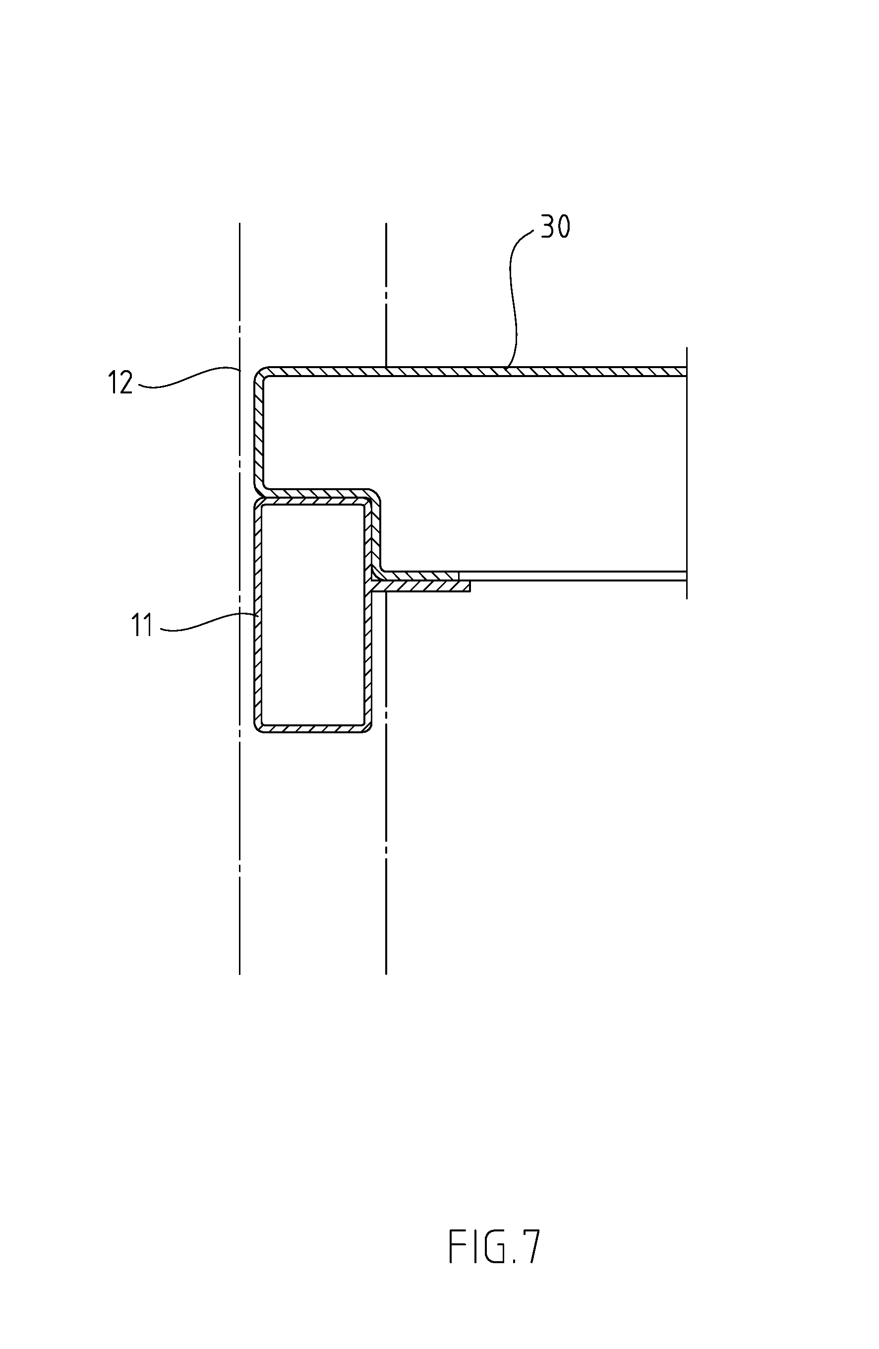
FIG. 7 is the third embodiment of placing bearing plate in FIG. 3.
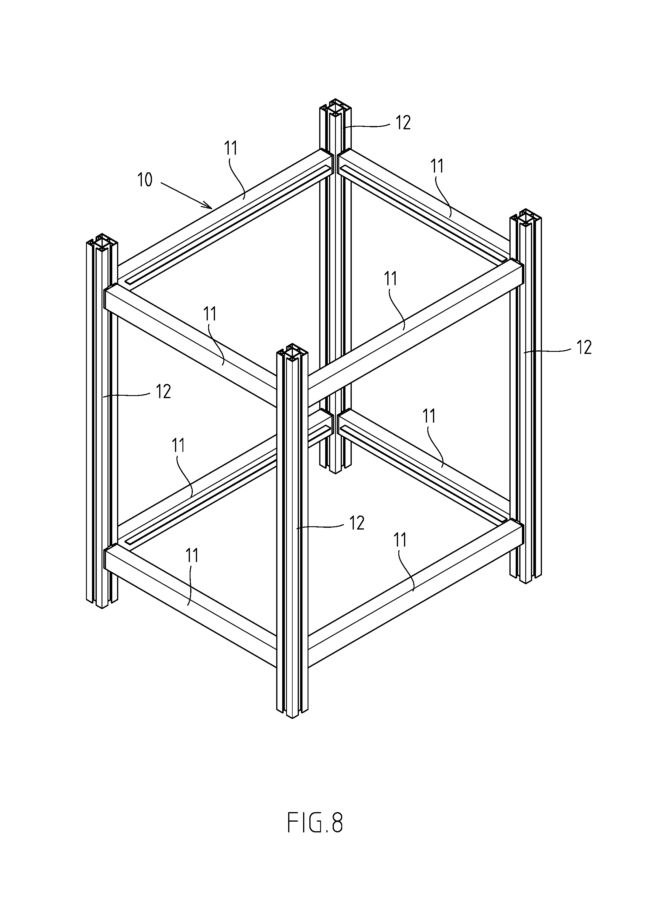
FIG. 8 is a three-dimensional assembly diagram of the second embodiment of the present invention.
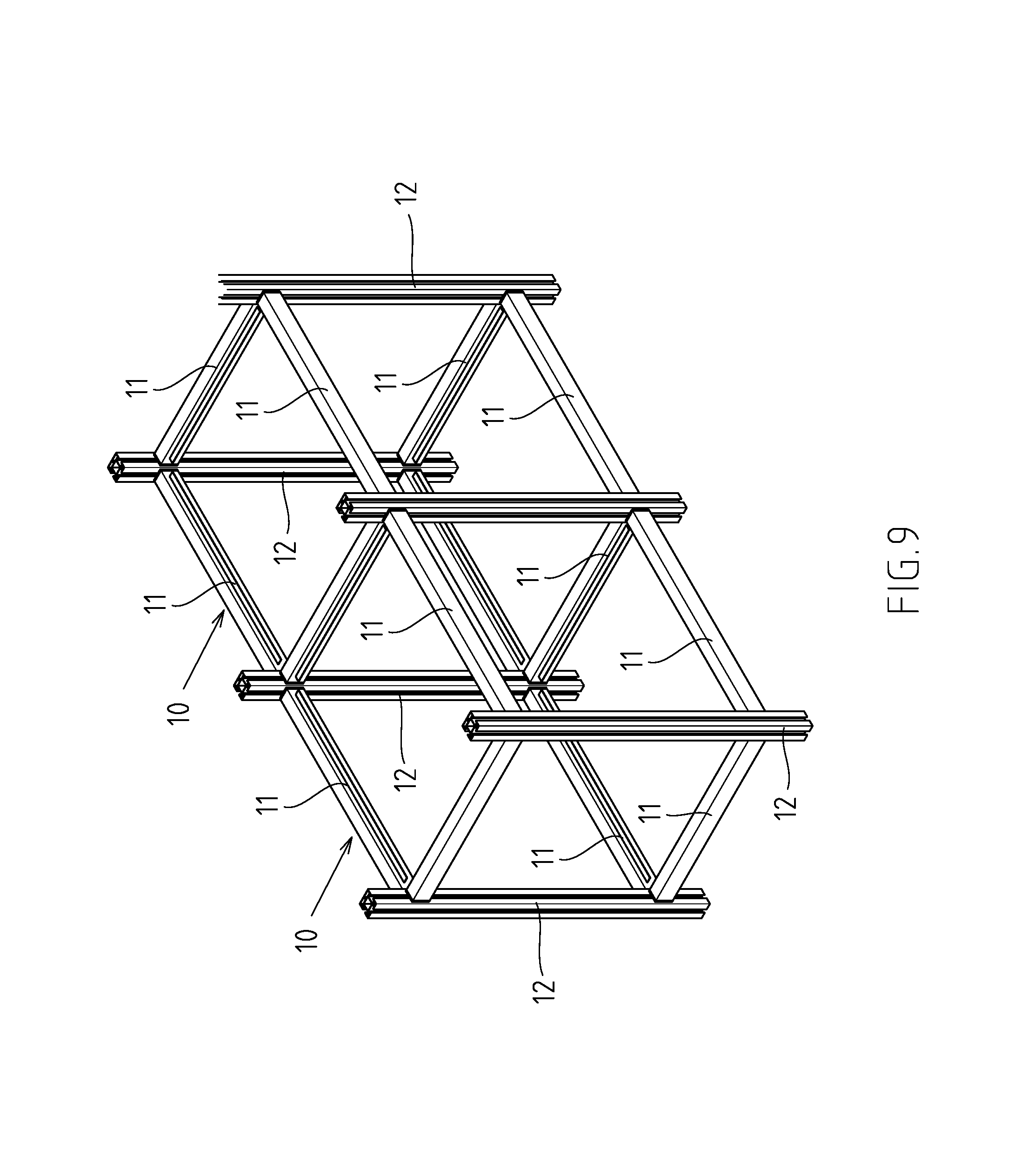
FIG. 9 is a three-dimensional assembly diagram of the second embodiment of the present invention.
DETAILED DESCRIPTION OF THE INVENTION
Referring to FIGS. 1 to 4, which are the first embodiment of a frame with connecting and positioning structure of the present invention. However, this embodiment is for illustrative purposes only, and is not limited by the patent application. The frame 10 has a plurality of cross bars 11 and a plurality of vertical bars 12, and the cross bars 11 and the vertical bars 12 are correspondingly connected through the connecting and positioning structure 20 without requiring any hand tools. Assembly and disassembly can be easily and quickly achieved to attain the objective of saving time and convenience. The connecting and positioning structure 20 mainly comprises: a fixing seat 21 fixed to the end of the cross bar 11 and having a plate body 211 for covering the end face of the cross bar 11; a fitting groove 212 provided on the fixing seat 21 and its plate body 211; one end of the fitting groove 212 is extended toward the bottom edge of the cross bar 11 to form an opening end 213, and the fitting groove 212 is in an inner-wide and outer-narrow structure type along the axial direction of the cross bar 11; an embedded block 22 for embedding in the retaining groove 121 of the vertical bar 12; a plug-in column 23 which is connected with the embedded block 22, and a shrinkage convex portion 231 is extended at an end of the plug-in column 23 connected to the embedded block 22; a step portion 232 is formed between the shrinkage convex portion 231 and the plug-in column 23; the shrinkage convex portion 231 is used to embed into the retaining groove 121; as the shrinkage convex portion 231 is limited by the wall 122 of the opening of the retaining groove 121, the plug-in column 23 in unable to rotate relative to the vertical bar 12; further, the step portion 232 rests on the wall 122 of the opening of the retaining groove 121, so that the step portion 232 and the embedded block 22 are retained to the wall 122 of the opening of the retaining groove 121; a fitting convex portion 24 is connected to the other end of the plug-in column 23, and the fitting convex portion 24 and the plug-in column 23 coincide with the fitting groove 212, showing an inner-wide and outer-narrow structure pattern, for inserting into the fitting groove 212 in a tight fit state; and a fixing member 25 penetrating the embedded block 22, the fitting convex portion 24, and the plug-in column 23 to connect them together.
In this embodiment, a second shrinkage convex portion 214 is disposed at a position near the closed end 217 of the plate body 211 of the fixing seat 21 for inserting into the retaining groove 121. Because the second shrinkage convex portion 214 is limited by the wall 122 of the opening of the retaining groove 121, the fixing seat 21 cannot be deflected relative to the vertical bar 12. In addition, a sleeve part 215 is extended from the plate body 211 of the fixing seat 21 towards the inside of the cross bar 11, and a buckle part 216 is protruded from the bottom edge of the sleeve part 215. The inner wall of the cross rod 11 has a positioning hole 111 for the buckle part 216 to be embedded.
In this embodiment, the other end of the fitting groove 212 away from the opening end 213 extends inwardly along the radial direction of the cross bar 11 to form a closed end 217 in a concave arc shape. The closed end 217 of the fitting groove 212 is in a concave arc shape, and the plug-in column 23 has a convex arc-shaped abutment surface 233 corresponding to the closed end 217. In this way, due to the structural design of the abutment surface 233 of the plug-in column 23 corresponding to the closed end 217 of the fitting groove 212, insertion of the fitting convex portion 24 into the fitting groove 212 is achieved to realize the oriented combination fool proof effect.
In this embodiment, a positioning protrusion 241 is formed on the end face of the fitting convex portion 24 abutted against the bottom of the fitting groove 212, and a positioning groove 218 is formed on the groove wall of the fitting groove 212 adjacent to the opening end 213. The positioning protrusion 241 is selectively embedded in the positioning groove 218 to make the fitting convex portion 24 positioned in the fixing seat 21. Furthermore, a guide slope 219 is formed on the groove wall of the fitting groove 212 adjacent to the opening end 213, so that when the fixing seat 21 is inserted into the fitting groove 212, the positioning protrusion 241 is aligned with the guide slope 219 and guided by the guide slope 219 to allow the fixing seat 21 to smoothly and quickly insert into the fitting groove 212.
As shown in FIGS. 5 to 7, the frame 10 is used for installation a bearing plate 30. After the installation, it provides the function of placing and storage. The type of the bearing plate 30 and its assembly method can be configured according to the user's needs.
FIG. 8 shows the second embodiment of the present invention. The main difference from the first embodiment is that the frame 10 can be further assembled into a rack through the extra cross bars 11 or vertical bars 12, and the connecting and positioning structure 20 is located at each corner of the rack. FIG. 9 shows the third embodiment of the present invention. The main difference from the second embodiment is that the frame 10 can form a transversely expanded double-row rack according to the user's needs through the extra cross bars 11 or vertical bars 12
* * * * *
D00000
D00001
D00002
D00003
D00004
D00005
D00006
D00007
D00008
D00009
XML
uspto.report is an independent third-party trademark research tool that is not affiliated, endorsed, or sponsored by the United States Patent and Trademark Office (USPTO) or any other governmental organization. The information provided by uspto.report is based on publicly available data at the time of writing and is intended for informational purposes only.
While we strive to provide accurate and up-to-date information, we do not guarantee the accuracy, completeness, reliability, or suitability of the information displayed on this site. The use of this site is at your own risk. Any reliance you place on such information is therefore strictly at your own risk.
All official trademark data, including owner information, should be verified by visiting the official USPTO website at www.uspto.gov. This site is not intended to replace professional legal advice and should not be used as a substitute for consulting with a legal professional who is knowledgeable about trademark law.