Cellular glass corrosion under insulation system
Badger Feb
U.S. patent number 10,201,955 [Application Number 15/204,276] was granted by the patent office on 2019-02-12 for cellular glass corrosion under insulation system. This patent grant is currently assigned to Owens Corning Intellectual Capital, LLC. The grantee listed for this patent is Pittsburgh Corning Corporation. Invention is credited to Steven Robert Badger.


| United States Patent | 10,201,955 |
| Badger | February 12, 2019 |
Cellular glass corrosion under insulation system
Abstract
A cellular glass system for an outer surface of a pipe. An insulation layer surrounds the outer surface of the pipe. The insulation layer has an outer surface and an inner surface and comprises cellular glass. A foam fills an annular space between the outer surface of the pipe and the inner surface of the insulation layer and is configured to limit water intrusion into the annular space and attenuate sound. The system may also include another insulation layer and another foam layer between the two insulation layers.
| Inventors: | Badger; Steven Robert (Pittsburgh, PA) | ||||||||||
|---|---|---|---|---|---|---|---|---|---|---|---|
| Applicant: |
|
||||||||||
| Assignee: | Owens Corning Intellectual Capital,
LLC (Toledo, OH) |
||||||||||
| Family ID: | 57686043 | ||||||||||
| Appl. No.: | 15/204,276 | ||||||||||
| Filed: | July 7, 2016 |
Prior Publication Data
| Document Identifier | Publication Date | |
|---|---|---|
| US 20170009914 A1 | Jan 12, 2017 | |
Related U.S. Patent Documents
| Application Number | Filing Date | Patent Number | Issue Date | ||
|---|---|---|---|---|---|
| 62189442 | Jul 7, 2015 | ||||
| Current U.S. Class: | 1/1 |
| Current CPC Class: | F16L 59/143 (20130101); B32B 17/066 (20130101); F16L 55/0336 (20130101); F16L 59/024 (20130101); B32B 3/10 (20130101); B32B 9/046 (20130101); F16L 58/1054 (20130101); B32B 17/064 (20130101); B32B 1/08 (20130101); F16L 59/025 (20130101); F16L 59/04 (20130101); B32B 5/18 (20130101); B32B 2307/102 (20130101); B32B 2266/0285 (20130101); B32B 2266/08 (20130101); B32B 2266/00 (20130101); B32B 2266/0214 (20130101); B32B 2266/06 (20130101); B32B 2307/304 (20130101); B32B 2307/7265 (20130101); B32B 2597/00 (20130101) |
| Current International Class: | F16L 59/14 (20060101); B32B 9/04 (20060101); B32B 1/08 (20060101); B32B 3/10 (20060101); F16L 55/033 (20060101); B32B 17/06 (20060101); F16L 58/10 (20060101); B32B 5/18 (20060101) |
| Field of Search: | ;138/149,141,156,157 ;428/36.5,34.5,36.9,36.91 |
References Cited [Referenced By]
U.S. Patent Documents
| 3959541 | May 1976 | King et al. |
| 4287245 | September 1981 | Kikuchi |
| 4623585 | November 1986 | Linton et al. |
| 5569513 | October 1996 | Fidler |
| 5971034 | October 1999 | Heisey |
| 6403180 | June 2002 | Barrall |
| 6782922 | August 2004 | Migliorini |
| 2003/0213525 | November 2003 | Patel et al. |
| 2005/0022892 | February 2005 | Babineau, Jr. |
| 2010/0154917 | June 2010 | Batallas et al. |
| 2010/0193061 | August 2010 | Princell |
| 2012/0018178 | January 2012 | Stambaugh et al. |
| 2013/0291984 | November 2013 | Himmel |
| 203348828 | Dec 2013 | CN | |||
| 3813952 | Nov 1989 | DE | |||
| 2418080 | Feb 2012 | EP | |||
| 949230 | Feb 1964 | GB | |||
Other References
|
Foamglas Insulation Systems (Pittsburgh Corning USA) Feb. 2009. cited by applicant . Office Action from CN Application No. 201480055058.4 dated Aug. 1, 2018. cited by applicant . Extended European Search Report from EP Application No. 16821962.4 dated Nov. 29, 2018. cited by applicant. |
Primary Examiner: Brinson; Patrick F
Attorney, Agent or Firm: Calfee, Halter & Griswold LLP
Parent Case Text
CROSS-REFERENCE TO RELATED APPLICATION
This application claims the benefit under 35 U.S.C. .sctn. 119(e) of the earlier filing date of U.S. Provisional Patent Application No. 62/189,442 filed on Jul. 7, 2015, the disclosure of which is incorporated by reference herein.
Claims
What is claimed is:
1. A cellular glass corrosion under insulation system for an outer surface of a pipe comprising: a first insulation layer surrounding the outer surface of the pipe, wherein the first insulation layer has an outer surface and an inner surface, wherein the first insulation layer comprises cellular glass; a first annular space between the outer surface of the pipe and the inner surface of the first insulation layer; and a first foam filling the first annular space configured to limit water intrusion into the annular space and attenuate sound.
2. The cellular glass corrosion under insulation system of claim 1, further comprising: a second insulation layer surrounding the outer surface of the first insulation layer, wherein the second insulation layer has an outer surface and an inner surface, wherein the second insulation layer comprises cellular glass; a second annular space between the outer surface of the first insulation layer and the inner surface of the second insulation layer; a second foam filling the second annular space configured to limit water intrusion into the annular space and attenuate sound.
3. The cellular glass corrosion under insulation system of claim 1, wherein the first insulation layer comprises curved segments.
4. The cellular glass corrosion under insulation system of claim 3, wherein the curved segments are quarter segments.
5. The cellular glass corrosion under insulation system of claim 3, wherein the curved segments are half segments.
6. The cellular glass corrosion under insulation system of claim 3, further comprising joints between the curved segments, wherein the joints are closed with a sealant.
7. The cellular glass corrosion under insulation system of claim 2, wherein the first and second insulation layers comprise curved segments.
8. The cellular glass corrosion under insulation system of claim 7, wherein the curved segments are quarter segments.
9. The cellular glass corrosion under insulation system of claim 7, wherein the curved segments are half segments.
10. The cellular glass corrosion under insulation system of claim 2, wherein at least one of the first foam and the second foam is comprised of a material having a compression force of less than 2 psi at 25% compression.
11. The cellular glass corrosion under insulation system of claim 1, wherein the foam is closed cell.
12. The cellular glass corrosion under insulation system of claim 1, wherein the foam is open cell.
13. The cellular glass corrosion under insulation system of claim 1, further comprising a water resistant layer on the first foam.
14. The cellular glass corrosion under insulation system of claim 1, wherein the foam comprises a material selected from silicone sponges, silicone foams, polyimide foams, nitrile foams, and melamine foams.
15. A cellular glass corrosion under insulation system for an outer surface of a pipe comprising: a first insulation layer surrounding the outer surface of the pipe, wherein the first insulation layer has an outer surface and an inner surface, wherein the first insulation layer comprises cellular glass; a first annular space between the outer surface of the pipe and the inner surface of the first insulation layer; a first foam filling the first annular space configured to limit water intrusion into the annular space and attenuate sound; a second insulation layer surrounding the outer surface of the first insulation layer, wherein the second insulation layer has an outer surface and an inner surface, wherein the second insulation layer comprises cellular glass; a second annular space between the outer surface of the first insulation layer and the inner surface of the second insulation layer; and a second foam filling the second annular space configured to limit water intrusion into the annular space and attenuate sound.
16. The cellular glass corrosion under insulation system of claim 15, wherein the first insulation layer and the second insulation layer comprise curved segments.
17. The cellular glass corrosion under insulation system of claim 15, wherein the foam is closed cell.
18. The cellular glass corrosion under insulation system of claim 15, wherein the foam is open cell.
19. The cellular glass corrosion under insulation system of claim 15, further comprising a water resistant layer on at least one foam.
20. A cellular glass corrosion under insulation system for an outer surface of a pipe comprising: a first insulation layer surrounding the outer surface of the pipe, wherein the first insulation layer has an outer surface and an inner surface, wherein the first insulation layer comprises cellular glass; a first annular space between the outer surface of the pipe and the inner surface of the first insulation layer; and a first foam filling the first annular space configured to limit water intrusion into the annular space and attenuate sound; and a water resistant layer on the first foam.
Description
BACKGROUND
This application discloses an invention which is related, generally and in various embodiments, to cellular glass insulation systems.
Cellular glass may be fabricated into sections for various applications such as insulating industrial and commercial pipes as well as insulating vessels. While insulating these applications provides the necessary purpose of energy conservation or process control, other problems may arise. For instance, corrosion under insulation (CUI) may occur under cellular glass insulation where moisture has been allowed to migrate between the cellular glass insulation and the pipes or vessels which are typically comprised of metal. The temperature range for CUI generally occurs between 32.degree. F. and 400.degree. F. This includes liquid water that is trapped under the cellular glass insulation and has not been allowed to evaporate or be removed from the system.
SUMMARY OF THE INVENTION
According to embodiments of the invention, a foam is utilized to fill an annular spacer between the cellular glass insulation and the pipe or vessel being insulated. The foam, when compressed in the annular space, limits the intrusion of moisture under the surface of the cellular glass insulation, thereby eliminating or greatly reducing the risk of CUI. The preferred foam composition utilized will not degrade over the CUI temperature range. In addition, the foam and cellular glass insulation system has several other key attributes including the attenuation of sound. In particular, the foam can be placed either at the annular space of the metal and cellular glass insulation, between an inner and outer layer of the cellular glass insulation, or both at the annular space as well as between the layers of the cellular glass insulation. In addition, the densities of the products can be modified to produce the desired sound attenuation properties.
BRIEF DESCRIPTION OF THE DRAWINGS
For the invention to be clearly understood and readily practiced, the invention will be described in conjunction with the following figures, wherein like reference characters designate the same or similar elements, which figures are incorporated into and constitute a part of the specification, wherein:
FIG. 1a is a perspective view of a single layer system.
FIG. 1b is an end view of a single layer system having a single cellular glass insulation layer with curved quarter segments.
FIG. 1c is an end view of a single layer system having a single cellular glass insulation layer with curved half segments
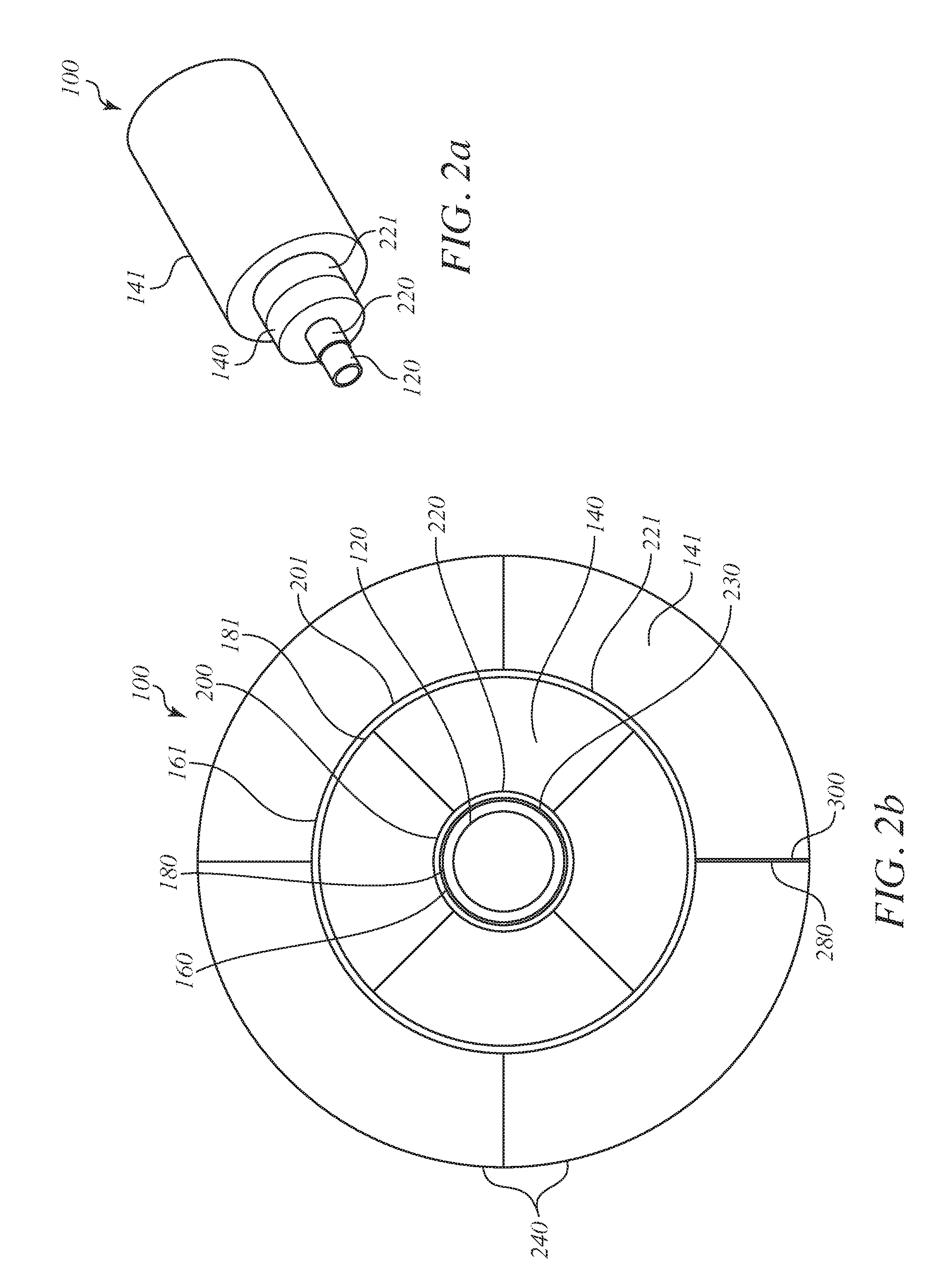
FIG. 2a is a perspective view of a double layer system.
FIG. 2b is an end view of a double layer system having two cellular glass insulation layers with curved quarter segments.
FIG. 2c is an end view of a double layer system having two cellular glass insulation layers with curved half segments.
DETAILED DESCRIPTION
Referring to FIGS. 1a to 1c, there is illustrated a single layer cellular glass insulation system generally designated by reference numeral 10 for a pipe 12 having a cellular glass insulation layer 14. A pipe and cellular glass insulation annular space or interface 16 is between an outer surface 18 of pipe 12 and an inner surface 20 of cellular glass insulation layer 14. A foam 22 fills the pipe and cellular glass insulation interface 16. Foam 22 limits water intrusion into pipe and cellular glass insulation interface 16 and attenuates sound. The preferred foam material does not degrade over the application temperature range. Example foam materials include silicone sponges, silicone foams, polyimide foams, nitrile foams, and melamine foams. A primary consideration when choosing the foam is the compressibility of the foam. The foam material should have a compression force of less than 2 psi at 25% compression utilizing ASTM D 1056 test procedure. Ideally, the foam material will have a 25% compression force rating per this test at less than 1 psi. This property is significant in that it defines the compressibility of the foam between the rigid metal of the pipe and cellular glass insulation layer. A foam material that is difficult to compress will not perform as desired. The foam 22 may be open or closed celled. If the foam is open-celled, it must compress to a level that significantly limits moisture migration under the cellular glass insulation layer or it must include another CUI mitigating property such as a hydrophobe, corrosion inhibitor, or water resistant coating/finish. The foam 22 may contain a water resistant layer 23 (FIG. 1b) such as aluminum foil, stainless steel foil, or other spray applied product. An example of the spray applied product is a urethane or silicone coating. In addition, the foam may contain a hydrophobe to limit moisture migration through the foam and/or a corrosion inhibitor. The corrosion inhibitor will be either impregnated into the foam or sprayed on the surface in contact with metal.
Foam 22 may also be placed to attenuate sound The sound attenuation properties must be tested for the chosen foam material but testing has shown that a foam placed between the rigid cellular glass insulation layer and the metal of the pipe will lower and attenuate sound levels. Utilizing multiple layers of foams with the cellular glass insulation layer will give improved performance. In addition, the utilization of a higher density cellular glass insulation layer (8-15 pcf) with the foam will provide improved performance for low frequency sounds. The cellular glass insulation layer 14 and foam 22 may either be applied in the field or applied prior to installation at the project site.
First cellular glass insulation layer 14 may either be curved segments, such as quarter segments 24 as shown FIG. 1b or two half clam shells, such as half segments 26 as shown in FIG. 1c. Joints 28 between edges of the segments 24, 26 may be sealed with a sealant 30 such as silicone.
Referring to FIGS. 2a to 2c, there is illustrated a double layer cellular glass insulation system generally designated by reference numeral 100 for a pipe 120 having a first cellular glass insulation layer 140 and a second cellular glass insulation layer 141. A pipe and cellular glass insulation interface 160 is between an outer surface 180 of pipe 120 and an inner surface 200 of first cellular glass insulation layer 140. A first foam 220 fills pipe and cellular glass insulation interface 160. A cellular glass insulation layer interface 161 is between an outer surface 181 of first cellular glass insulation layer 140 and an inner surface 201 of second cellular glass insulation layer 141. A second foam 221 fills cellular glass insulation layer interface 161. Like the embodiment of FIGS. 1b and 1c, cellular glass insulation layers 140 and 141 may either either have curved segments, such as quarter segments 240 as shown FIG. 2b or two half clam shells, such as half segments 260 as shown in FIG. 2c. Joints 280 are rotated such that the joints 280 on the cellular glass insulation layers 140 and 141 are not in the same radial position, but are offset to one another. Like the embodiment of FIGS. 1b and 1c, the embodiments of FIGS. 2a and 2b may include sealant 300 in joint 280 and a water resistant layer 230 on foam 220.
Although the present invention has been described in detail for the purpose of illustration, it is to be understood that such detail is solely for that purpose and that variations can be made therein by those in the art without departing from the spirit and scope of the invention.
* * * * *
D00000
D00001
D00002
D00003
D00004
XML
uspto.report is an independent third-party trademark research tool that is not affiliated, endorsed, or sponsored by the United States Patent and Trademark Office (USPTO) or any other governmental organization. The information provided by uspto.report is based on publicly available data at the time of writing and is intended for informational purposes only.
While we strive to provide accurate and up-to-date information, we do not guarantee the accuracy, completeness, reliability, or suitability of the information displayed on this site. The use of this site is at your own risk. Any reliance you place on such information is therefore strictly at your own risk.
All official trademark data, including owner information, should be verified by visiting the official USPTO website at www.uspto.gov. This site is not intended to replace professional legal advice and should not be used as a substitute for consulting with a legal professional who is knowledgeable about trademark law.