Electronic cigarette and method of assembling electronic cigarette
Lin Feb
U.S. patent number 10,201,188 [Application Number 15/303,745] was granted by the patent office on 2019-02-12 for electronic cigarette and method of assembling electronic cigarette. The grantee listed for this patent is Guangrong Lin. Invention is credited to Guangrong Lin.


| United States Patent | 10,201,188 |
| Lin | February 12, 2019 |
Electronic cigarette and method of assembling electronic cigarette
Abstract
Disclosed is an electronic cigarette including a battery connector and a vaporizer connector, wherein the battery connector comprises two recessed L-shaped grooves, and the vaporizer connector comprises two symmetrically-arranged protrusions. After the battery connector has been twist-lock connected with the vaporizer connector, the L-shaped grooves of the battery connector tightly engage with the protrusions of the vaporizer connector, positive and negative electrodes of a battery assembly are electrically connected to two electrodes of a vaporizer electrode assembly.
| Inventors: | Lin; Guangrong (Guangdong, CN) | ||||||||||
|---|---|---|---|---|---|---|---|---|---|---|---|
| Applicant: |
|
||||||||||
| Family ID: | 51673576 | ||||||||||
| Appl. No.: | 15/303,745 | ||||||||||
| Filed: | March 20, 2015 | ||||||||||
| PCT Filed: | March 20, 2015 | ||||||||||
| PCT No.: | PCT/CN2015/074710 | ||||||||||
| 371(c)(1),(2),(4) Date: | October 13, 2016 | ||||||||||
| PCT Pub. No.: | WO2015/158195 | ||||||||||
| PCT Pub. Date: | October 22, 2015 |
Prior Publication Data
| Document Identifier | Publication Date | |
|---|---|---|
| US 20170035117 A1 | Feb 9, 2017 | |
Foreign Application Priority Data
| Apr 16, 2014 [CN] | 2014 2 0184089 U | |||
| Current U.S. Class: | 1/1 |
| Current CPC Class: | A24F 47/008 (20130101); A24F 47/00 (20130101); H01M 2/1055 (20130101); F16B 7/20 (20130101); A61M 15/06 (20130101); Y02E 60/10 (20130101); H01M 2220/30 (20130101) |
| Current International Class: | F16B 7/20 (20060101); A61M 15/06 (20060101); A24F 47/00 (20060101); H01M 2/10 (20060101) |
References Cited [Referenced By]
U.S. Patent Documents
| 4911573 | March 1990 | Pietro |
| 2013/0180410 | July 2013 | Jing |
| 2014/0041658 | February 2014 | Goodman |
| 2014/0174458 | June 2014 | Katz |
| 2014/0261493 | September 2014 | Smith |
| 2015/0013701 | January 2015 | Liu |
| 2015/0027467 | January 2015 | Liu |
| 2015/0059784 | March 2015 | Liu |
| 2015/0201674 | July 2015 | Dooly |
| 2015/0223522 | August 2015 | Ampolini |
| 2016/0338405 | November 2016 | Liu |
| 2017/0071252 | March 2017 | Liu |
| 2017/0172207 | June 2017 | Liu |
| 102389166 | Mar 2012 | CN | |||
| 203523808 | Apr 2014 | CN | |||
Other References
|
International Search Report of PCT Patent Application No. PCT/CN2015/074710 dated Jun. 17, 2015. cited by applicant. |
Primary Examiner: Abraham; Ibrahime A
Assistant Examiner: Bae; Gyounghyun
Claims
What is claimed is:
1. An electronic cigarette comprising a battery assembly and a vaporizer assembly abutting the battery assembly, characterized in that a battery connector at a connecting end of the battery assembly and a vaporizer connector at a connecting end of the vaporizer assembly are connected via a twist lock joint, an electrode of the battery connector is electrically connected to an electrode of the vaporizer connector; the battery connector is consisted of a tube body and a protruding platform formed on one end of the tube body and having a cross-sectional area smaller than the tube body, wherein a circular cavity is provided at the center of the protruding platform, two recessed L-shaped grooves are radially and symmetrically formed in an inner wall of the circular cavity, a through hole is opened at a bottom of the circular cavity, positive and negative electrodes of the battery assembly are protruded out from the through hole, an outer wall of the protruding platform has a protrusion for snap fitting with a corresponding protrusion formed at an inner wall of one end of an outer tube of the vaporizer assembly; the vaporizer connector comprises a tube body and a circular protruding platform formed on one end of the tube body and having a cross-sectional area smaller than the tube body, two symmetrically-arranged protrusions protrude radially outward from an outer wall of the circular protruding platform, a center of the circular protruding platform is provided with a vaporizer electrode assembly comprising two electrodes; after the battery connector has been twist-lock connected with the vaporizer connector, the circular cavity of the battery connector exactly receives the circular protruding platform of the vaporizer connector, the L-shaped grooves of the battery connector tightly engage with the protrusions of the vaporizer connector, the positive and negative electrodes of the battery assembly are electrically connected to the two electrodes of the vaporizer electrode assembly; the vaporizer electrode assembly is consisted of a column-shaped electrode fixer inserted into a central through hole of the circular protruding platform, a rod-like electrode having a protruding ring at one end thereof and inserted into a central through hole of the column-shaped electrode fixer, and a semi-annular electrode or a full-annular electrode inserted into an annular cavity recessed along an outer circumference of the central through hole of the electrode fixer.
2. The electronic cigarette of claim 1, characterized in that the L-shaped groove is consisted of a vertical groove and an arc-shaped groove starting from a bottom half of the vertical groove and extending along a portion of the circumference of the inner wall of the circular cavity, wherein a height of the arc-shaped groove is slightly and gradually decreased.
3. The electronic cigarette of claim 2, characterized in that a lug is protruded downward from a top edge of the arc-shaped groove for locking purpose.
4. The electronic cigarette of claim 3, characterized in that the protrusion of the vaporizer connector has a concave portion configured to engage with the lug at the top edge of the arc-shaped groove.
5. The electronic cigarette of claim 1, characterized in that the positive and negative electrodes of the battery assembly are rod-like and retractable electrodes.
6. The electronic cigarette of claim 1, characterized in that the battery assembly, the vaporizer assembly and the outer tube of the vaporizer assembly all have non-circular cross sections.
7. The electronic cigarette of claim 6, characterized in that the non-circular cross section is oval cross section.
8. The electronic cigarette of claim 7, characterized in that an angle between the major axis X of an oval end surface of an oval protruding platform of the battery connector and a straight line between two midpoints of two vertical grooves of the symmetrically-arranged L-shaped grooves is an acute angle.
Description
FIELD OF THE INVENTION
The present invention relates to an electronic cigarette and a method of assembling an electronic cigarette.
BACKGROUND OF THE INVENTION
A vaporizer assembly and a battery assembly of an existing electronic cigarette having a non-circular cross section are usually connected via a nested structure, other connecting structures are neither user-friendly nor convenient for the assembly and disassembly of the components of an electronic cigarette having a non-circular cross section.
SUMMARY OF THE INVENTION
The present invention aims to provide an electronic cigarette comprising a vaporizer assembly and a battery assembly connected via a twist lock joint. Such twist lock joint is very convenient for the assembly and disassembly of components of an electronic cigarette having a non-circular cross section. Another object of the present invention is to provide a convenient method of assembling an electronic cigarette.
A technical solution of the present invention is an electronic cigarette comprising a battery assembly and a vaporizer assembly abutting the battery assembly, wherein a battery connector at a connecting end of the battery assembly and a vaporizer connector at a connecting end of the vaporizer assembly are connected via a twist lock joint, an electrode of the battery connector is electrically connected to an electrode of the vaporizer connector; the battery connector is consisted of a tube body and a protruding platform formed on one end of the tube body and having a cross-sectional area smaller than the tube body, wherein a circular cavity is provided at the center of the protruding platform, two recessed L-shaped grooves are radially and symmetrically formed in an inner wall of the circular cavity, a through hole is opened at a bottom of the circular cavity, positive and negative electrodes of the battery assembly are protruded out from the through hole, an outer wall of the protruding platform has a protrusion for snap fitting with a corresponding protrusion formed at an inner wall of one end of an outer tube of the vaporizer assembly; the vaporizer connector comprises a tube body and a circular protruding platform formed on one end of the tube body and having a cross-sectional area smaller than the tube body, two symmetrically-arranged protrusions protrude radially outward from an outer wall of the circular protruding platform, a center of the circular protruding platform is provided with a vaporizer electrode assembly comprising two electrodes, after the battery connector has been twist-lock connected with the vaporizer connector, the circular cavity of the battery connector exactly receives the circular protruding platform of the vaporizer connector, the L-shaped grooves of the battery connector tightly engage with the protrusions of the vaporizer connector, the positive and negative electrodes of the battery assembly are electrically connected to the two electrodes of the vaporizer electrode assembly.
Preferably, the L-shaped groove is consisted of a vertical groove and an arc-shaped groove starting from a bottom half of the vertical groove and extending along a portion of the circumference of the inner wall of the circular cavity, wherein a height of the arc-shaped groove is slightly and gradually decreased.
Preferably, a lug is protruded downward from a top edge of the arc-shaped groove for locking purpose.
Preferably, the protrusion of the vaporizer connector has a concave portion configured to engage with the lug at the top edge of the arc-shaped groove.
Preferably, the positive and negative electrodes of the battery assembly are rod-like and retractable electrodes.
Preferably, the vaporizer electrode assembly is consisted of a column-shaped electrode fixer inserted into a central through hole of the circular protruding platform, a rod-like electrode having a protruding ring at one end thereof and inserted into a central through hole of the column-shaped electrode fixer, and a semi-annular electrode inserted into an annular cavity recessed along an outer circumference of the central through hole of the electrode fixer.
Preferably, that the vaporizer electrode assembly is consisted of a column-shaped electrode fixer inserted into a central through hole of the circular protruding platform, a rod-like electrode having a protruding ring at one end thereof and inserted into a central through hole of the column-shaped electrode fixer, and a full-annular electrode inserted into an annular cavity recessed along an outer circumference of the central through hole of the electrode fixer.
Preferably, the battery assembly, the vaporizer assembly and the outer tube of the vaporizer assembly all have non-circular cross sections.
Preferably, the non-circular cross section is oval cross section.
Preferably, an angle between the major axis X of an oval end surface of the oval protruding platform of the battery connector and a straight line between two midpoints of two vertical grooves of the symmetrically-arranged L-shaped grooves is an acute angle.
Another technical solution of the present invention is a method of assembling an electronic cigarette comprising a battery assembly and a vaporizer assembly abutting the battery assembly, wherein the method comprises aligning a protrusion of a vaporizer connector to an L-shaped groove of a battery connector; inserting a circular protruding platform of the vaporizer assembly into a circular cavity of the battery connector; twisting the vaporizer connector to a locking position so as to enable positive and negative electrodes of the battery connector to be electrically connected to a semi-annular electrode and a rod-like electrode of the vaporizer connector, wherein the rod-like electrode has a protruding ring at one end thereof; sheathing the vaporizer assembly with an outer tube of the vaporizer assembly; and engaging a protrusion of an outer wall of a protruding platform with a corresponding protrusion of the outer tube of the vaporizer assembly to complete a snap fit therebetween.
The technical solutions of the present invention have the following advantage. The twist lock joint between the vaporizer assembly and the battery assembly can be employed for various types of electronic cigarettes having non-circular cross section.
BRIEF DESCRIPTION OF THE DRAWINGS
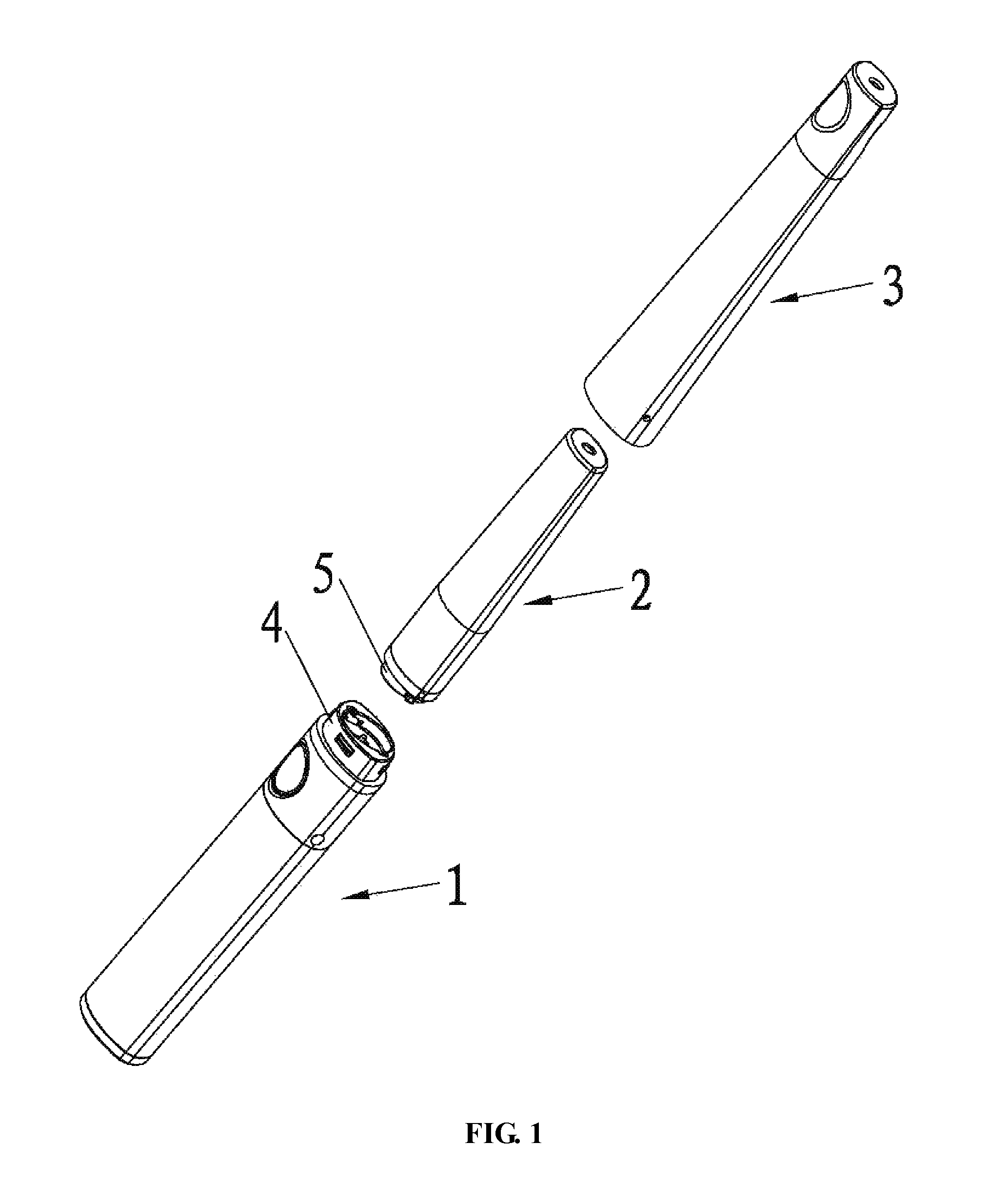
FIG. 1 is a perspective exploded view of an electronic cigarette of the present invention.
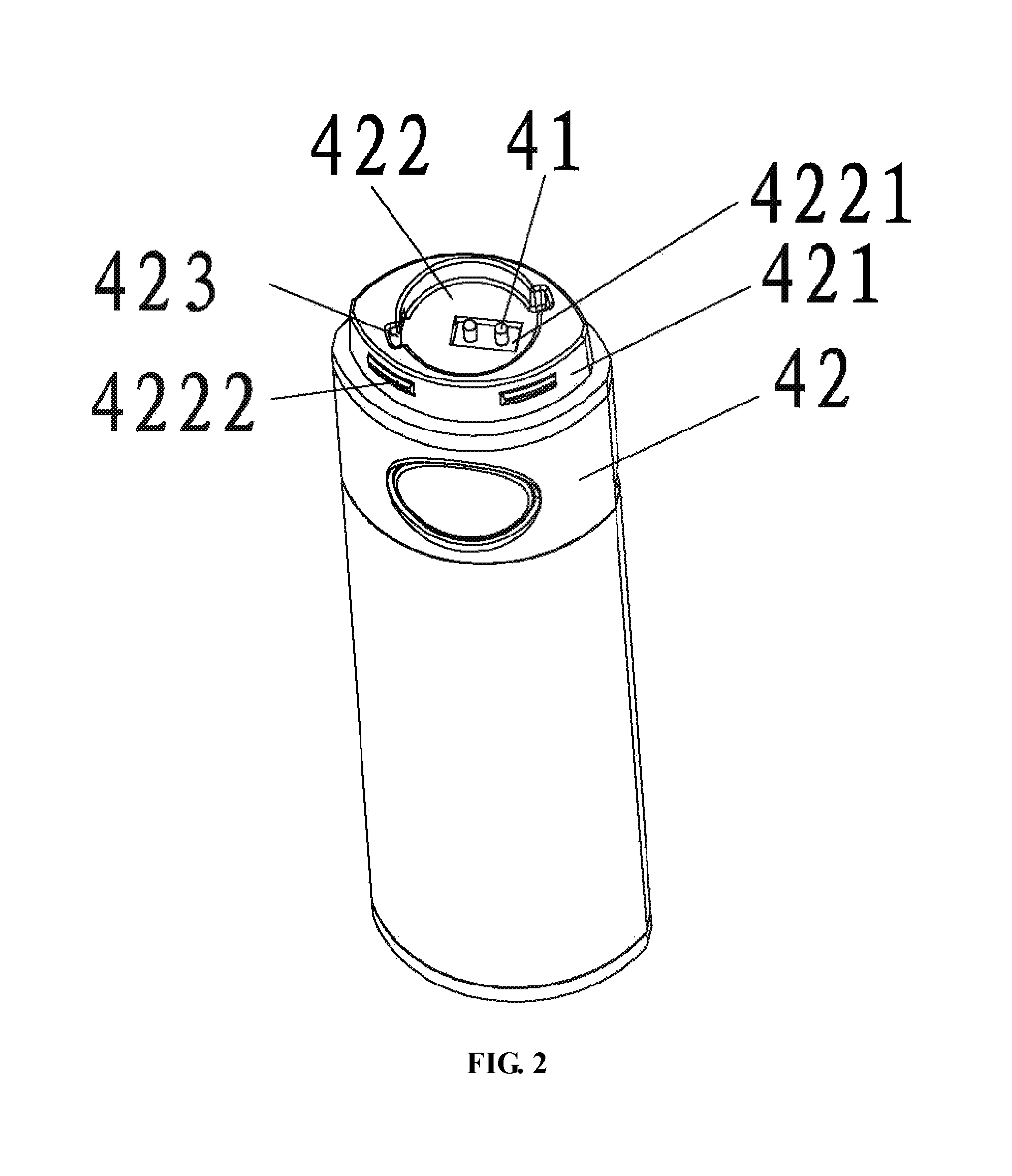
FIG. 2 is a schematic view showing a battery connector of an electronic cigarette of the present invention.
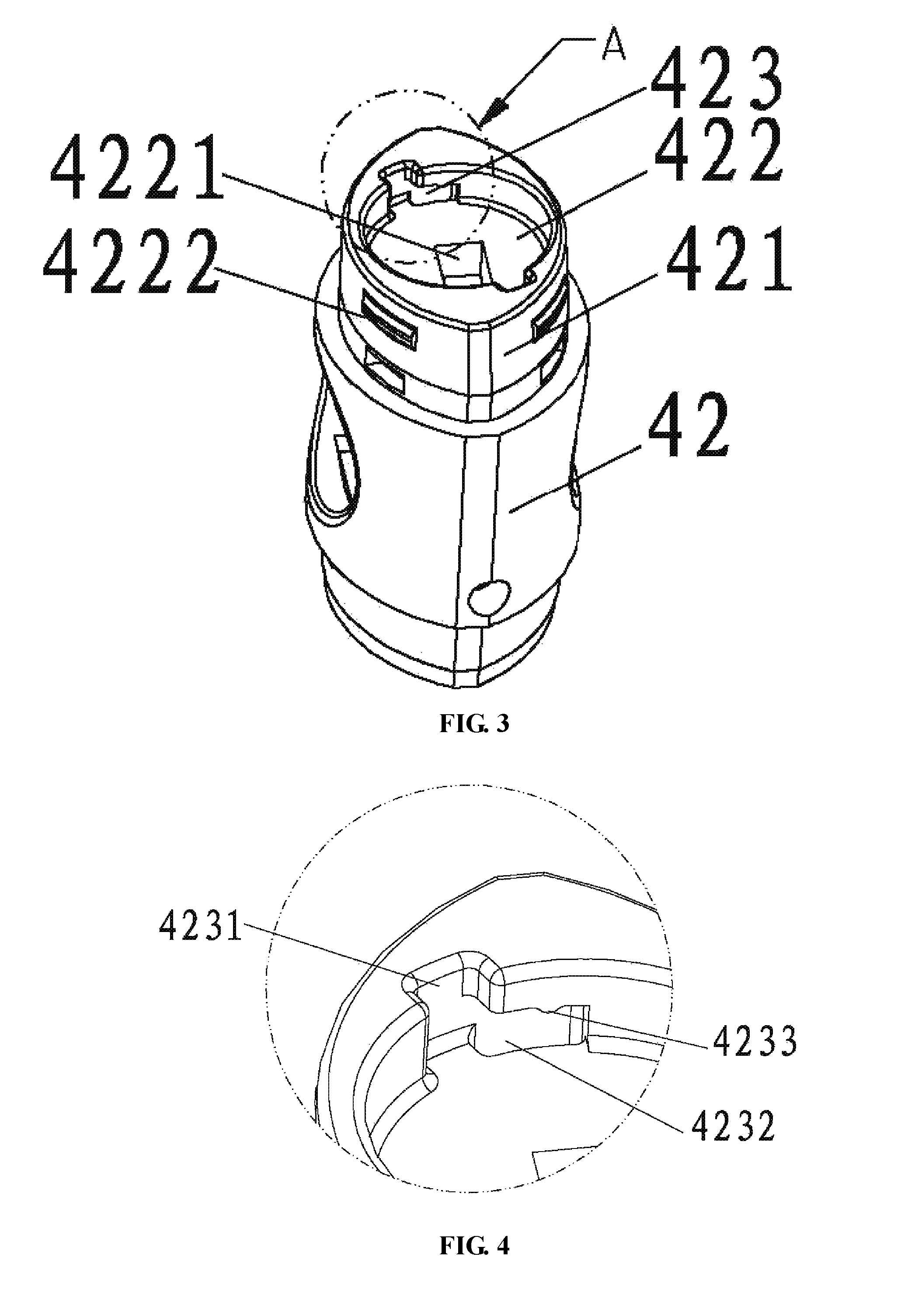
FIG. 3 is another schematic view showing a battery connector of an electronic cigarette of the present invention.
FIG. 4 is an enlarged partial view of the battery connector shown in FIG. 3.
FIG. 5 is a schematic view showing an acute angle between the major axis X of an oval end surface of a protruding platform of a battery connector and a straight line between two midpoints of two vertical grooves of two symmetrically-arranged L-shaped grooves.
FIG. 6 is a schematic view showing a vaporizer connector of an electronic cigarette of the present invention.
FIG. 7 is another schematic view showing a vaporizer connector of an electronic cigarette of the present invention.
FIG. 8 is a perspective exploded view of a vaporizer electrode assembly of an electronic cigarette of the present invention.
FIG. 9 is an enlarged schematic view showing a semi-annular electrode of the vaporizer electrode assembly shown in FIG. 8.
FIG. 10 is another perspective exploded view of a vaporizer electrode assembly of an electronic cigarette of the present invention.
FIG. 11 is a full-annular electrode of the vaporizer electrode assembly shown in FIG. 10
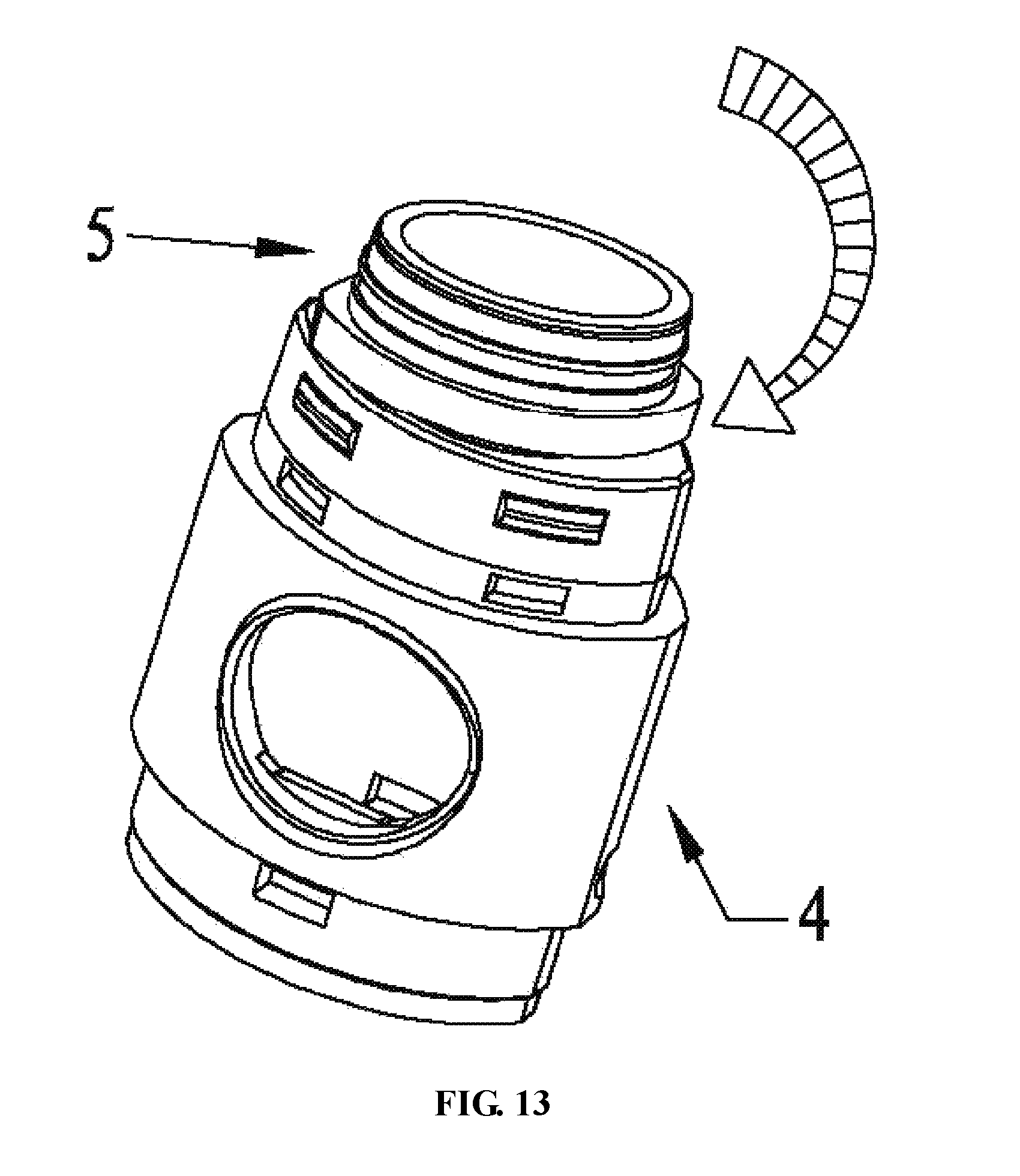
FIGS. 12, 13 and 14 are schematic views showing a twist-lock mechanism between a vaporizer assembly and a battery assembly of an electronic cigarette of the present invention.
LIST OF REFERENCE NUMERALS OF MAIN COMPONENTS
1 battery assembly 2 vaporizer assembly 3 outer tube of vaporizer assembly 4 battery connector 41 electrode 42 tube body 421 protruding platform 422 circular cavity 4221 through hole 4222 protrusion 423 L-shaped groove 4231 vertical groove 4232 arc-shaped groove 4233 lug 5 vaporizer connector 51 tube body 511 air inlet 52 protrusion 521 concave portion 53 circular protruding platform 54 central through hole 6 vaporizer electrode assembly 61 semi-annular electrode 611 electrode plate 612 insertion electrode plate 62 rod-like electrode 63 electrode fixer 631 annular cavity 632 central through hole 633 insertion groove
DETAILED DESCRIPTION OF ILLUSTRATED EMBODIMENTS
Various preferred embodiments will now be described with reference to the figures.
Referring to FIGS. 1, 2 and 6, an electronic cigarette comprises a battery assembly 1, a vaporizer assembly 2 abutting the battery assembly 1, and an outer tube 3 of the vaporizer assembly 2, the outer tube 3 sheathing the vaporizer assembly 2 and having a snap fit with the battery assembly 1. A battery connector 4 at a connecting end of the battery assembly 1 and a vaporizer connector 5 at a connecting end of the vaporizer assembly 2 are connected via a twist lock joint. An electrode 41 of the battery connector 4 is electrically connected to a semi-annular electrode 61 and a rod-like electrode 62 of the vaporizer connector 5, wherein the rod-like electrode 62 has a protruding ring at one end thereof.
Referring to FIG. 1, the battery assembly 1, the vaporizer assembly 2 and the outer tube 3 of the vaporizer assembly 2 all have oval cross sections.
Referring to FIGS. 2 and 3, the battery connector 4 is consisted of a tube body 42, and a protruding platform 421 formed on one end of the tube body 42 and having a cross-sectional area smaller than the tube body 42. A circular cavity 422 is provided at the center of the protruding platform 421. Two recessed L-shaped grooves 423 are radially and symmetrically formed in an inner wall of the circular cavity 422. A through hole 4221 is opened at a bottom of the circular cavity 422. Positive and negative electrodes 41 of the battery assembly 1 are protruded out from the through hole 4221. An outer wall of the protruding platform 421 has a protrusion 4222 for snap fitting with a corresponding protrusion (not shown in the figures) formed at an inner wall of one end of the outer tube 3 of the vaporizer assembly 2.
Referring to FIG. 4, the L-shaped groove 423 is consisted of a vertical groove 4231 and an arc-shaped groove 4232 smoothly communicating with the vertical groove 4231. The arc-shaped groove 4232 starts from a bottom half of the vertical groove 4231 and extends along a portion of the circumference of the inner wall of the circular cavity 422. A lug 4233 is protruded downward from a top edge of the arc-shaped groove 4232 for locking purpose.
Referring to FIG. 5, an angle between the major axis X of an oval end surface of the oval protruding platform 421 of the battery connector 4 and a straight line between two midpoints of the two vertical grooves 4231 of the symmetrically-arranged L-shaped grooves 423 is an acute angle.
Referring to FIGS. 6 and 7, the vaporizer connector 5 comprises a tube body 51, an air inlet 511 of an air passage opened in the tube body 51, and a circular protruding platform 53 formed on one end of the tube body 51 and having a cross-sectional area smaller than the tube body 51. Two symmetrically-arranged protrusions 52 protrude radially outward from an outer wall of the circular protruding platform 53. A center of the circular protruding platform 53 is provided with a vaporizer electrode assembly 6. The vaporizer electrode assembly 6 comprises two electrodes 61, 62.
Referring to FIGS. 8 and 9, the vaporizer electrode assembly 6 is consisted of a column-shaped electrode fixer 63 inserted into a central through hole 54 of the circular protruding platform 53, a rod-like electrode 62 having a protruding ring at one end thereof and inserted into a central through hole 632 of the column-shaped electrode fixer 63, and a semi-annular electrode 61 inserted into both an annular cavity 631 recessed along an outer circumference of the central through hole 632 of the electrode fixer 63 and an insertion groove 633 provided at a bottom of the annular cavity 631. The semi-annular electrode 61 is consisted of a semi-annular electrode plate 611 and two insertion electrode plates 612 protruding perpendicularly from two ends of the semi-annular electrode plate 611.
Referring to FIGS. 10 and 11, in another embodiment the vaporizer electrode assembly 6 is consisted of a column-shaped electrode fixer 63 inserted into a central through hole 54 of the circular protruding platform 53, a rod-like electrode 62 having a protruding ring at one end thereof and inserted into a central through hole 632 of the column-shaped electrode fixer 63, and a full-annular electrode 61 inserted into both an annular cavity 631 recessed along an outer circumference of the central through hole 632 of the electrode fixer 63 and an insertion groove 633 provided at a bottom of the annular cavity 631. The full-annular electrode 61 is consisted of a full-annular electrode plate 611 and two insertion electrode plate 612 protruding symmetrically and perpendicularly from the full-annular electrode plate 611.
Referring to FIGS. 1, 12, 13 and 14, a method of assembling the above-mentioned electronic cigarette, comprising aligning the protrusion 52 of the vaporizer connector 5 to the L-shaped grooves 423 of the battery connector 4; inserting the circular protruding platform 53 of the vaporizer assembly 2 into the circular cavity 422 of the battery connector 4; twisting the vaporizer connector 5 to a locking position so as to enable the positive and negative electrodes 41 of the battery connector 4 to be electrically connected to the semi-annular electrode 61 and the rod-like electrode 62 of the vaporizer connector 5, wherein the rod-like electrode 62 has a protruding ring at one end thereof; sheathing the vaporizer assembly 2 with the outer tube 3 of the vaporizer assembly 2; engaging the protrusion 4222 of the outer wall of the protruding platform 421 with the corresponding protrusion (not shown in the figures) of the outer tube of vaporizer assembly 3 to complete a snap fit therebetween.
All the above are the preferred embodiments of the present invention, and the invention is intended to cover various modifications and equivalent arrangements included within the scope of the invention.
* * * * *
D00000
D00001
D00002
D00003
D00004
D00005
D00006
D00007
D00008
D00009
D00010
XML
uspto.report is an independent third-party trademark research tool that is not affiliated, endorsed, or sponsored by the United States Patent and Trademark Office (USPTO) or any other governmental organization. The information provided by uspto.report is based on publicly available data at the time of writing and is intended for informational purposes only.
While we strive to provide accurate and up-to-date information, we do not guarantee the accuracy, completeness, reliability, or suitability of the information displayed on this site. The use of this site is at your own risk. Any reliance you place on such information is therefore strictly at your own risk.
All official trademark data, including owner information, should be verified by visiting the official USPTO website at www.uspto.gov. This site is not intended to replace professional legal advice and should not be used as a substitute for consulting with a legal professional who is knowledgeable about trademark law.