Integrated multi-mode mammography/tomosynthesis X-ray system and method
DeFreitas , et al. Fe
U.S. patent number 10,194,875 [Application Number 15/411,502] was granted by the patent office on 2019-02-05 for integrated multi-mode mammography/tomosynthesis x-ray system and method. This patent grant is currently assigned to Hologic, Inc.. The grantee listed for this patent is Hologic, Inc.. Invention is credited to Kenneth DeFreitas, Thomas Farbizio, Baorui Ren, Christopher Ruth, Ian Shaw, Andrew P. Smith, Jay Stein.


View All Diagrams
| United States Patent | 10,194,875 |
| DeFreitas , et al. | February 5, 2019 |
Integrated multi-mode mammography/tomosynthesis X-ray system and method
Abstract
A system for multi-mode breast x-ray imaging which comprises a compression arm assembly for compressing and immobilizing a breast for x-ray imaging, an x-ray tube assembly, an x-ray image receptor, and a patient shield is provided. The system is configured for a plurality of imaging protocols and modes.
| Inventors: | DeFreitas; Kenneth (Patterson, NY), Farbizio; Thomas (Newtown, CT), Ren; Baorui (Andover, MA), Ruth; Christopher (Boxford, MA), Shaw; Ian (Yorktown Heights, NY), Smith; Andrew P. (Lexington, MA), Stein; Jay (Boston, MA) | ||||||||||
|---|---|---|---|---|---|---|---|---|---|---|---|
| Applicant: |
|
||||||||||
| Assignee: | Hologic, Inc. (Marlborough,
MA) |
||||||||||
| Family ID: | 36498527 | ||||||||||
| Appl. No.: | 15/411,502 | ||||||||||
| Filed: | January 20, 2017 |
Prior Publication Data
| Document Identifier | Publication Date | |
|---|---|---|
| US 20170128028 A1 | May 11, 2017 | |
Related U.S. Patent Documents
| Application Number | Filing Date | Patent Number | Issue Date | ||
|---|---|---|---|---|---|
| 14498476 | Sep 26, 2014 | 9549709 | |||
| 14058385 | Jun 30, 2015 | 9066706 | |||
| 13462342 | Oct 22, 2013 | 8565374 | |||
| 12954971 | May 8, 2012 | 8175219 | |||
| 11791601 | Jan 11, 2011 | 7869563 | |||
| PCT/US2005/042613 | Nov 23, 2005 | ||||
| 60631296 | Nov 26, 2004 | ||||
| Current U.S. Class: | 1/1 |
| Current CPC Class: | A61B 6/4417 (20130101); A61B 6/025 (20130101); A61B 6/502 (20130101); A61B 6/107 (20130101); A61B 6/4452 (20130101); G06T 2207/30068 (20130101); A61B 6/4291 (20130101); A61B 6/482 (20130101) |
| Current International Class: | A61B 6/04 (20060101); A61B 6/00 (20060101); A61B 6/10 (20060101); A61B 6/02 (20060101) |
References Cited [Referenced By]
U.S. Patent Documents
| 3365575 | January 1968 | Strax |
| 3502878 | March 1970 | Stewart |
| 3863073 | January 1975 | Wagner |
| 3971950 | July 1976 | Evans et al. |
| 4160906 | July 1979 | Daniels et al. |
| 4310766 | January 1982 | Finkenzeller et al. |
| 4380086 | April 1983 | Vagi |
| 4496557 | January 1985 | Malen et al. |
| 4513433 | April 1985 | Weiss et al. |
| 4542521 | September 1985 | Hahn et al. |
| 4559641 | December 1985 | Caugant et al. |
| 4662379 | May 1987 | Macovski |
| 4706269 | November 1987 | Reina et al. |
| 4721856 | January 1988 | Saotome |
| 4744099 | May 1988 | Huettenrauch et al. |
| 4752948 | June 1988 | MacMahon |
| 4760589 | July 1988 | Siczek et al. |
| 4773086 | September 1988 | Fujita et al. |
| 4773087 | September 1988 | Plewes |
| 4819258 | April 1989 | Kleinman et al. |
| 4821727 | April 1989 | Levene et al. |
| 4969174 | November 1990 | Scheid et al. |
| 4989227 | January 1991 | Tirelli et al. |
| 5018176 | May 1991 | Romeas et al. |
| RE33634 | July 1991 | Yanaki |
| 5029193 | July 1991 | Saffer |
| 5051904 | September 1991 | Griffith |
| 5078142 | January 1992 | Siczek et al. |
| 5163075 | November 1992 | Lubinsky et al. |
| 5164976 | November 1992 | Scheid et al. |
| 5199056 | March 1993 | Darrah |
| 5212637 | May 1993 | Saxena |
| 5240011 | August 1993 | Assa |
| 5256370 | October 1993 | Slattery et al. |
| 5289520 | February 1994 | Pellegrino et al. |
| 5291539 | March 1994 | Thumann et al. |
| 5359637 | October 1994 | Webber |
| 5365562 | November 1994 | Toker |
| 5415169 | May 1995 | Siczek et al. |
| 5426685 | June 1995 | Pellegrino et al. |
| 5452367 | September 1995 | Bick et al. |
| 5506877 | April 1996 | Niklason et al. |
| 5526394 | June 1996 | Siczek et al. |
| 5539797 | July 1996 | Heidsieck et al. |
| 5553111 | September 1996 | Moore et al. |
| 5592562 | January 1997 | Rooks |
| 5594769 | January 1997 | Pellegrino et al. |
| 5596200 | January 1997 | Sharma et al. |
| 5598454 | January 1997 | Franetzke et al. |
| 5609152 | March 1997 | Pellegrino et al. |
| 5627869 | May 1997 | Andrew et al. |
| 5657362 | August 1997 | Giger et al. |
| 5668844 | September 1997 | Webber |
| 5668889 | September 1997 | Hara |
| 5706327 | January 1998 | Adamkowski et al. |
| 5719952 | February 1998 | Rooks |
| 5735264 | April 1998 | Siczek et al. |
| 5769086 | June 1998 | Ritchart et al. |
| 5803912 | September 1998 | Siczek et al. |
| 5818898 | October 1998 | Tsukamoto et al. |
| 5828722 | October 1998 | Ploetz et al. |
| 5844965 | December 1998 | Galkin |
| 5872828 | February 1999 | Niklason et al. |
| 5878104 | March 1999 | Ploetz |
| 5896437 | April 1999 | Ploetz |
| 5941832 | August 1999 | Tumey et al. |
| 5970118 | October 1999 | Sokolov |
| 5986662 | November 1999 | Argiro et al. |
| 5999836 | December 1999 | Nelson et al. |
| 6005907 | December 1999 | Ploetz |
| 6022325 | February 2000 | Siczek et al. |
| 6075879 | June 2000 | Roehrig et al. |
| 6091841 | July 2000 | Rogers et al. |
| 6137527 | October 2000 | Abdel-Malek et al. |
| 6141398 | October 2000 | He et al. |
| 6149301 | November 2000 | Kautzer et al. |
| 6175117 | January 2001 | Komardin et al. |
| 6196715 | March 2001 | Nambu et al. |
| 6207958 | March 2001 | Giakos |
| 6216540 | April 2001 | Nelson et al. |
| 6219059 | April 2001 | Argiro |
| 6233473 | May 2001 | Shepherd et al. |
| 6243441 | June 2001 | Zur |
| 6244507 | June 2001 | Garland |
| 6256370 | July 2001 | Yavuz |
| 6272207 | August 2001 | Tang |
| 6289235 | September 2001 | Webber et al. |
| 6292530 | September 2001 | Yavus et al. |
| 6327336 | December 2001 | Gingold et al. |
| 6341156 | January 2002 | Baetz et al. |
| 6345194 | February 2002 | Nelson et al. |
| 6375352 | April 2002 | Hewes et al. |
| 6411836 | June 2002 | Patel et al. |
| 6415015 | July 2002 | Nicolas et al. |
| 6442288 | August 2002 | Haerer et al. |
| 6459925 | October 2002 | Nields et al. |
| 6480565 | November 2002 | Ning |
| 6490476 | December 2002 | Townsend et al. |
| 6501819 | December 2002 | Unger et al. |
| 6556655 | April 2003 | Chichereau et al. |
| 6574304 | June 2003 | Hsieh et al. |
| 6574629 | June 2003 | Cooke, Jr. et al. |
| 6597762 | July 2003 | Ferrant et al. |
| 6611575 | August 2003 | Alyassin et al. |
| 6620111 | September 2003 | Stephens et al. |
| 6626849 | September 2003 | Huitema et al. |
| 6633674 | October 2003 | Barnes et al. |
| 6638235 | October 2003 | Miller et al. |
| 6647092 | November 2003 | Eberhard et al. |
| 6744848 | June 2004 | Stanton et al. |
| 6748044 | June 2004 | Sabol et al. |
| 6751285 | June 2004 | Eberhard et al. |
| 6758824 | July 2004 | Miller et al. |
| 6813334 | November 2004 | Koppe et al. |
| 6882700 | April 2005 | Wang et al. |
| 6885724 | April 2005 | Li et al. |
| 6909790 | June 2005 | Tumey et al. |
| 6909792 | June 2005 | Carrott et al. |
| 6912319 | June 2005 | Barnes et al. |
| 6940943 | September 2005 | Claus et al. |
| 6957099 | October 2005 | Arnone et al. |
| 6970531 | November 2005 | Eberhard et al. |
| 6978040 | December 2005 | Berestov |
| 6987831 | January 2006 | Ning |
| 6999554 | February 2006 | Mertelmeier |
| 7110490 | September 2006 | Eberhard et al. |
| 7110502 | September 2006 | Tsuji |
| 7123684 | October 2006 | Jing et al. |
| 7127091 | October 2006 | Op De Beek et al. |
| 7142633 | November 2006 | Eberhard et al. |
| 7245694 | July 2007 | Jing et al. |
| 7302031 | November 2007 | Hjarn et al. |
| 7315607 | January 2008 | Ramsauer |
| 7319735 | January 2008 | Defreitas et al. |
| 7323692 | January 2008 | Rowlands et al. |
| 7430272 | September 2008 | Jing et al. |
| 7443949 | October 2008 | Defreitas et al. |
| 7577282 | August 2009 | Gkanatsios et al. |
| 7583786 | September 2009 | Jing et al. |
| 7609806 | October 2009 | Defreitas et al. |
| 7616801 | November 2009 | Gkanatsios et al. |
| 7630531 | December 2009 | Chui |
| 7630533 | December 2009 | Ruth et al. |
| 7688940 | March 2010 | Defreitas et al. |
| 7697660 | April 2010 | Ning |
| 7702142 | April 2010 | Ren et al. |
| 7760853 | July 2010 | Jing et al. |
| 7760924 | July 2010 | Ruth et al. |
| 7792245 | September 2010 | Hitzke et al. |
| 7831296 | November 2010 | Defreitas et al. |
| 7869563 | January 2011 | Defreitas et al. |
| 7881428 | February 2011 | Jing et al. |
| 7894646 | February 2011 | Shirahata et al. |
| 7916915 | March 2011 | Gkanatsios et al. |
| 7949091 | May 2011 | Jing et al. |
| 7986765 | July 2011 | Defreitas et al. |
| 7991106 | August 2011 | Ren et al. |
| 8131049 | March 2012 | Ruth et al. |
| 8155421 | April 2012 | Ren et al. |
| 8170320 | May 2012 | Smith et al. |
| 8175219 | May 2012 | Defreitas et al. |
| 8285020 | October 2012 | Gkanatsios et al. |
| 8416915 | April 2013 | Jing et al. |
| 8452379 | May 2013 | DeFreitas et al. |
| 8559595 | October 2013 | Defreitas et al. |
| 8565372 | October 2013 | Stein et al. |
| 8565374 | October 2013 | DeFreitas et al. |
| 8571289 | October 2013 | Ruth et al. |
| 8712127 | April 2014 | Ren et al. |
| 8831171 | September 2014 | Jing et al. |
| 9042612 | May 2015 | Gkanatsios et al. |
| 9066706 | June 2015 | Defreitas et al. |
| 9460508 | October 2016 | Gkanatsios et al. |
| 9498175 | November 2016 | Stein et al. |
| 9549709 | January 2017 | DeFreitas et al. |
| 2001/0038681 | November 2001 | Stanton et al. |
| 2002/0012450 | January 2002 | Tsujii |
| 2002/0048343 | April 2002 | Launay et al. |
| 2002/0050986 | May 2002 | Inouc et al. |
| 2002/0070970 | June 2002 | Wood et al. |
| 2002/0075997 | June 2002 | Unger et al. |
| 2002/0090055 | July 2002 | Zur et al. |
| 2002/0122533 | September 2002 | Marie et al. |
| 2003/0007598 | January 2003 | Wang et al. |
| 2003/0018272 | January 2003 | Treado et al. |
| 2003/0026386 | February 2003 | Tang et al. |
| 2003/0072409 | April 2003 | Kaufhold et al. |
| 2003/0072417 | April 2003 | Kaufhold et al. |
| 2003/0073895 | April 2003 | Nields et al. |
| 2003/0095624 | May 2003 | Eberhard et al. |
| 2003/0097055 | May 2003 | Yanof et al. |
| 2003/0169847 | September 2003 | Karellas et al. |
| 2003/0194050 | October 2003 | Eberhard |
| 2003/0194051 | October 2003 | Wang et al. |
| 2003/0194121 | October 2003 | Eberhard et al. |
| 2003/0210254 | November 2003 | Doan et al. |
| 2003/0212327 | November 2003 | Wang et al. |
| 2003/0215120 | November 2003 | Uppaluri et al. |
| 2004/0008809 | January 2004 | Webber |
| 2004/0066882 | April 2004 | Eberhard et al. |
| 2004/0066884 | April 2004 | Hermann Claus et al. |
| 2004/0066904 | April 2004 | Eberhard et al. |
| 2004/0070582 | April 2004 | Smith et al. |
| 2004/0094167 | May 2004 | Brady et al. |
| 2004/0101095 | May 2004 | Jing et al. |
| 2004/0109529 | June 2004 | Eberhard et al. |
| 2004/0146221 | July 2004 | Siegel et al. |
| 2004/0171986 | September 2004 | Tremaglio, Jr. et al. |
| 2004/0267157 | December 2004 | Miller et al. |
| 2005/0049521 | March 2005 | Miller et al. |
| 2005/0063509 | March 2005 | DeFreitas et al. |
| 2005/0078797 | April 2005 | Danielsson et al. |
| 2005/0105679 | May 2005 | Wu et al. |
| 2005/0113681 | May 2005 | DeFreitas et al. |
| 2005/0113715 | May 2005 | Schwindt et al. |
| 2005/0129172 | June 2005 | Mertelmeier |
| 2005/0135555 | June 2005 | Claus et al. |
| 2005/0135664 | June 2005 | Kaufhold et al. |
| 2005/0226375 | October 2005 | Eberhard et al. |
| 2006/0030784 | February 2006 | Miller et al. |
| 2006/0074288 | April 2006 | Kelly |
| 2006/0098855 | May 2006 | Gkanatsios et al. |
| 2006/0129062 | June 2006 | Nicoson et al. |
| 2006/0155209 | July 2006 | Miller et al. |
| 2006/0269041 | November 2006 | Mertelmeier |
| 2006/0291618 | December 2006 | Eberhard et al. |
| 2007/0030949 | February 2007 | Jing et al. |
| 2007/0036265 | February 2007 | Jing et al. |
| 2007/0076844 | April 2007 | Defreitas et al. |
| 2007/0078335 | April 2007 | Horn |
| 2007/0140419 | June 2007 | Souchay |
| 2007/0223651 | September 2007 | Wagenaar et al. |
| 2007/0225600 | September 2007 | Weibrecht et al. |
| 2007/0242800 | October 2007 | Jing et al. |
| 2008/0019581 | January 2008 | Gkanatsios et al. |
| 2008/0045833 | February 2008 | Defreitas et al. |
| 2008/0101537 | May 2008 | Sendai |
| 2008/0112534 | May 2008 | Defreitas |
| 2008/0130979 | June 2008 | Ren |
| 2008/0212861 | September 2008 | Durgan et al. |
| 2009/0003519 | January 2009 | Defreitas et al. |
| 2009/0010384 | January 2009 | Jing et al. |
| 2009/0080594 | March 2009 | Brooks et al. |
| 2009/0080602 | March 2009 | Brooks et al. |
| 2009/0135997 | May 2009 | Defreitas et al. |
| 2009/0141859 | June 2009 | Gkanatsios et al. |
| 2009/0213987 | August 2009 | Stein et al. |
| 2009/0238424 | September 2009 | Arakita et al. |
| 2009/0268865 | October 2009 | Ren et al. |
| 2009/0296882 | December 2009 | Gkanatsios |
| 2009/0304147 | December 2009 | Jing et al. |
| 2010/0034450 | February 2010 | Mertelmeier |
| 2010/0054400 | March 2010 | Ren |
| 2010/0086188 | April 2010 | Ruth |
| 2010/0150306 | June 2010 | Defreitas et al. |
| 2010/0195882 | August 2010 | Ren |
| 2010/0226475 | September 2010 | Smith |
| 2010/0290585 | November 2010 | Eliasson |
| 2011/0069809 | March 2011 | Defreitas et al. |
| 2011/0178389 | July 2011 | Kumar et al. |
| 2011/0234630 | September 2011 | Batman et al. |
| 2012/0051502 | March 2012 | Ohta |
| 2013/0028374 | January 2013 | Gkanatsios et al. |
| 2013/0272494 | October 2013 | DeFreitas et al. |
| 2014/0044230 | February 2014 | Stein et al. |
| 2014/0044231 | February 2014 | Defreitas et al. |
| 2014/0086471 | March 2014 | Ruth et al. |
| 2014/0098935 | April 2014 | Defreitas et al. |
| 2014/0232752 | August 2014 | Ren et al. |
| 2014/0376690 | December 2014 | Jing et al. |
| 2015/0049859 | February 2015 | DeFreitas et al. |
| 2015/0160848 | June 2015 | Gkanatsios et al. |
| 2015/0310611 | October 2015 | Gkanatsios et al. |
| 2016/0270742 | September 2016 | Stein et al. |
| 2017/0024113 | January 2017 | Gkanatsios et al. |
| 2017/0135650 | May 2017 | Stein et al. |
| 102004051401 | May 2006 | DE | |||
| 0775467 | May 1997 | EP | |||
| 0982001 | Mar 2000 | EP | |||
| 1428473 | Jun 2004 | EP | |||
| 1759637 | Mar 2007 | EP | |||
| 1569556 | Apr 2012 | EP | |||
| 2602743 | Nov 2014 | EP | |||
| 53151381 | Apr 1972 | JP | |||
| 53151381 | Nov 1978 | JP | |||
| 2001-346786 | Dec 2001 | JP | |||
| 2002219124 | Aug 2002 | JP | |||
| 2006-231054 | Sep 2006 | JP | |||
| 2007-50264 | Mar 2007 | JP | |||
| 2007-521911 | Aug 2007 | JP | |||
| 2007229269 | Sep 2007 | JP | |||
| 2008-67933 | Mar 2008 | JP | |||
| 200886471 | Apr 2008 | JP | |||
| 2009500048 | Jan 2009 | JP | |||
| WO 90/05485 | May 1990 | WO | |||
| WO 98/16903 | Apr 1998 | WO | |||
| WO 00/51484 | Sep 2000 | WO | |||
| WO 03/020114 | Mar 2003 | WO | |||
| WO 2003/057564 | Jul 2003 | WO | |||
| WO 2004/043535 | May 2004 | WO | |||
| WO 2005/051197 | Jun 2005 | WO | |||
| WO 2005/110230 | Nov 2005 | WO | |||
| WO 2005/112767 | Dec 2005 | WO | |||
| WO 2006/055830 | May 2006 | WO | |||
| WO 2006/058160 | Jun 2006 | WO | |||
Other References
|
"Essentials for life: Senographe Essential Full-Field Digital Mammography system", GE Health-care Brochure, MM-0132-05.06-EN-US, 2006, 12 pgs. cited by applicant . "Filtered Back Projection," (NYGREN) published May 8, 2007; URL:http://web.archive.org/web/19991010131715/http://www.owlnet.rice.edu/- -.about.e1ec539/Projects97/cult/node2.html., 2 pgs. cited by applicant . "Lorad Selenia" Document B-BI-SEO US/Intl (May 2006) copyright Hologic 2006, 12 pgs. cited by applicant . ACRIN website, located at https://www.acrin.org/PATIENTS/ABOUTIMAGINGEXAMSANDAGENTS/ABOUTMAMMOGRAPH- YANDTOMOSYNTHESIS.aspx, "About Mammography and Tomosnythesis", obtained online on Dec. 8, 2015, 5 pgs. cited by applicant . American College of Radiology website, located at http://www.acr.org/FAQs/DBT-FAQ, "Digital Breast Tomosynthesis FAQ for Insurers", obtained online on Dec. 8, 2015, 2 pages. cited by applicant . Aslund, Magnus, "Digital Mammography with a Photon Counting Detector in a Scanned Multislit Geometry", Doctoral Thesis, Dept of Physics, Royal Institute of Technology, Stockholm, Sweden, Apr. 2007, 51 pages. cited by applicant . Chan, Heang-Ping et al., "ROC study of the effect of stereoscopic imaging on assessment of breast lesions", Medical Physics, vol. 32, No. 4, Apr. 2005, 7 pgs. cited by applicant . Cole, Elodia, et al., "The Effects of Gray Scale Image Processing on Digital Mammography Interpretation Performance", Academic Radiology, vol. 12, No. 5, pp. 585-595, May 2005. cited by applicant . Digital Clinical Reports, Tomosynthesis, GE Brochure 98-5493, Nov. 1998, 8 pgs. cited by applicant . Dobbins, James T., "Digital x-ray tomosynthesis: current state of the art and clinical potential," Physics in Medicine and Biology, Taylor and Francis Ltd, London GB, vol. 48, No. 19, Oct. 7, 2003, 42 pages. cited by applicant . Federica Pediconi et al., "Color-coded automated signal intensity-curve for detection and characterization of breast lesions: Preliminary evaluation of a new software for MR-based breast imaging", International Congress Series 1281 (2005) 1081-1086. cited by applicant . Grant, David G., "Tomosynthesis: a three-dimensional imaging technique", IEEE Trans. Biomed. Engineering, vol. BME-19, #1, Jan. 1972, pp. 20-28. cited by applicant . Kita et al., "Correspondence between different view breast X-rays using simulation of breast deformation", Proceedings 1998 IEE Computer Society Conference on Computer Vision and Pattern Recognition, Santa Barbara, CA, Jun. 23-25, 1998, pp. 700-707. cited by applicant . Mammographic Accreditation Phantom, http://www.cirsinc.com/pdfs/015cp.pdf. (2006), 2 pgs. cited by applicant . Niklason, Loren T. et al., "Digital Tomosynthesis in Breast Imaging", Radiology, Nov. 1997, vol. 205, No. 2, pp. 399-406. cited by applicant . Pisano, Etta D., "Digital Mammography", Radiology, vol. 234, No. 2, Feb. 2005, pp. 353-362. cited by applicant . Senographe 700 & 800T (GE); 2-page download on Jun. 22, 2006 from www.gehealthcare.com/inen/rad/whe/products/mswh800t.html.; Figures 1-7 on 4 sheets re lateral shift compression paddle, 2 pgs. cited by applicant . Smith, A., "Fundamentals of Breast Tomosynthesis", White Paper, Hologic Inc., WP-00007, Jun. 2008, 8 pgs. cited by applicant . Smith, Andrew, PhD, "Full Field Breast Tomosynthesis", Hologic White Paper, Oct. 2004, 6 pgs. cited by applicant . Wheeler F. W., et al. "Micro-Calcification Detection in Digital Tomosynthesis Mammography", Proceedings of SPIE, Conf-Physics of Semiconductor Devices, Dec. 11, 2001 to Dec. 15, 2001, Delhi, SPIE, US, vol. 6144, Feb. 13, 2006, 12 pgs. cited by applicant . Wu, Tao, et al. "Tomographic Mammography Using a Limited Number of Low-Dose Cone-Beam Projection Images" Medical Physics, AIP, Melville, NY, vol. 30, No. 3, Mar. 1, 2003, p. 365-380. cited by applicant . Japanese Office Action mailed in Application 2016-087710, dated Mar. 1, 2017, 5 pages. cited by applicant . Japanese Office Action mailed in Application 2017-001579, dated Mar. 29, 2017, 1 page. (No English Translation.). cited by applicant. |
Primary Examiner: Midkiff; Anastasia
Parent Case Text
RELATED APPLICATION
This application is a continuation application and claims priority under 35 U.S.C. .sctn. 120 to U.S. patent application Ser. No. 14/498,476, filed Sep. 26, 2014, now U.S. Pat. No. 9,549,709; which is a continuation of U.S. patent application Ser. No. 14/058,385, filed Oct. 21, 2013, now U.S. Pat. No. 9,066,706; which is a continuation of U.S. patent application Ser. No. 13/462,342, filed May 2, 2012, now U.S. Pat. No. 8,565,374; which is a continuation of U.S. patent application Ser. No. 12/954,971, filed Nov. 29, 2010, now U.S. Pat. No. 8,175,219; which is a continuation of U.S. patent application Ser. No. 11/791,601, filed Feb. 22, 2008, now U.S. Pat. No. 7,869,563; which is a national stage entry of PCT/US2005/042613, filed Nov. 23, 2005; which claims priority to and the benefit of U.S. provisional patent application No. 60/631,296, filed Nov. 26, 2004. Each of the above is incorporated by reference.
Claims
The invention claimed is:
1. A system for multi-mode breast x-ray imaging comprising: a compression arm assembly for compressing a patient's breast for x-ray imaging; an x-ray image receptor; an x-ray tube assembly, wherein the compression arm assembly, the x-ray tube assembly, and the x-ray image receptor are configured for movement about an axis to accommodate a plurality of imaging modes, and wherein the x-ray tube assembly is configured to rotate relative to the compression arm for at least a tomosynthesis imaging mode of the plurality of imaging modes; and a patient shield secured to the compression arm assembly and spaced apart from the x-ray tube assembly, wherein during the tomosynthesis imaging mode the x-ray tube assembly is configured to rotate relative to at least a portion of the patient shield.
2. The system of claim 1, wherein the patient shield is configured to provide a mechanical interlock against patient contact with the rotating x-ray tube assembly.
3. The system of claim 1, wherein at least two of the plurality of imaging modes utilize a single breast compression.
4. The system of claim 3, wherein the plurality of imaging modes comprise a mammography imaging mode and the tomosynthesis imaging mode.
5. The system of claim 1, wherein the x-ray tube assembly moves continuously for image acquisition when the x-ray tube assembly rotates relative to the compression arm for at least one of the plurality of imaging modes.
6. The system of claim 1 further comprising an anti-scatter grid disposed adjacent to the x-ray image receptor for at least one of the plurality of imaging modes.
7. The system of claim 6, wherein the anti-scatter grid is retractable out of an imaging area for at least one of the plurality of imaging modes.
8. The system of claim 1, wherein the compression arm assembly comprises a breast compression paddle, wherein the breast compression paddle is configured to move laterally relative to the x-ray image receptor.
9. The system of claim 1, wherein the compression arm assembly comprises a receptor housing, wherein the x-ray image receptor is disposed within the receptor housing and is configured to rotatably rock about the axis therein.
10. The system of claim 9, wherein the movement of the x-ray tube assembly and the x-ray image receptor are at different angles about the axis for at least one of the plurality of imaging modes.
11. A system for multi-mode breast x-ray imaging comprising: a housing; an arm assembly rotatably secured to the housing; a receptor housing attached to the arm assembly; a compression paddle movably attached to the arm assembly; a patient shield attached to the arm assembly; an x-ray image receptor rotatably supported by the housing and disposed within the receptor housing; and an x-ray tube assembly having an x-ray source disposed at least partially therein, wherein the x-ray tube assembly is rotatably supported by the housing, wherein the arm assembly and the x-ray tube assembly are independently rotatable in relation to the housing, and wherein when the x-ray tube assembly rotates independently from the arm assembly, the patient shield is spaced apart from the x-ray tube assembly such that the x-ray tube assembly rotates independently from at least a portion of the patient shield.
12. The system of claim 11, wherein the patient shield is configured to provide a mechanical interlock against patient contact with the rotating x-ray source.
13. The system of claim 11, wherein the x-ray tube assembly moves continuously for image acquisition when the x-ray tube assembly rotates relative to the arm assembly.
14. The system of claim 11 further comprising an anti-scatter grid disposed between the compression paddle and the x-ray image receptor.
15. The system of claim 14, wherein the anti-scatter grid is retractable in relation to the x-ray image receptor.
16. The system of claim 11, wherein the compression paddle is laterally moveable on the arm assembly.
17. The system of claim 11, wherein the compression paddle is removable from the arm assembly.
18. The system of claim 11 further comprising a spacer disposed between the compression paddle and the x-ray image receptor.
Description
FIELD OF THE INVENTION
This patent specification pertains to x-ray mammography and, more specifically, to an integrated system for selectively carrying out x-ray mammography and/or tomosynthesis imaging and a method of using such a system.
BACKGROUND OF THE INVENTION
X-ray mammography has long been a screening modality for breast cancer and other lesions, and also has been relied on for diagnostic and other purposes. For many years, the breast image was recorded on x-ray film brat more recently digital x-ray image receptors have come into use, as in the Selenia.TM. mammography system available from Hologic, Inc. of Bedford, Mass. and its division Lorad Corporation of Danbury, Conn. For mammograms, a cone-shaped or pyramid-shaped x-ray beam passes through the compressed breast and forms a two-dimensional projection image. Any one of a number of orientation can be used, such as cranial-caudal (CC) or MLO (mediolateral-oblique) orientation. More recently, breast x-ray tomosynthesis has been proposed. The technology typically involves taking two-dimensional (2D) projection images of the immobilized breast at each of a number of angles of the x-ray beam relative to the breast and processing the resulting x-ray measurements to reconstruct images of breast slices that typically are in planes transverse to the x-ray beam axis, such as parallel to the image plane of a mammogram of the same breast. The range of angles is substantially less than in computerized tomography, i.e., substantially less than 180.degree., e.g. .+-.15.degree.. Tomosynthesis technology is described in U.S. patent application Ser. No. 10/723,486 filed Nov. 26, 2003; a prototype of a unit with at least some of the described features was shown at the 2003 Radiological Society of North America meeting in Chicago, Ill. Additional prototypes are in clinical testing in this country as of the filing of this patent specification. Other approaches to tomosynthesis also have been proposed: see, e.g., U.S. Pat. Nos. 4,496,557, 5,051,904, 5,359,637, 6,289,235, and 6,647,092, published U.S. Patent Applications Nos. 2001/0038861, 2004/066882, 2004/0066884, and 2004/0066904, and Digital Clinical Reports, Tomosynthesis (GE Brochure 98-5493, 11/98). How to reconstruct tomosynthesis images is discussed to DG Grant, "Tomosynthesis: a three-dimensional imaging technique", IEEE Trans. Biomed. Engineering, Vol BME-19, #1, (January 1972), pp 20-28. See, also, U.S. Provisional Application Ser. No. 60/628,516, filed Nov. 15, 2004, and entitled "Matching geometry generation and display of mammograms and tomosynthesis images". Mammography systems can also be used in interventional procedures, such as biopsy, by adding a biopsy station (for example, the StereoLoc II.TM. Upright Stereotactic Breast Biopsy System, which is available from Hologic, Inc.). The patents, applications, brochures, and article sited above are hereby incorporated by reference in this patent specification as though fully set forth herein.
In clinical use, it can be desirable for a number of reasons to assess both tomosynthesis images and conventional mammograms of the patient's breasts. For example, the decades of conventional mammograms have enabled medical professionals to develop valuable interpretation expertise. Mammograms may offer good visualization of microcalcifications, and can offer higher spatial resolution compared with tomosynthesis. Tomosynthesis images may have different desirable characteristics--e.g., they may offer better visualization of structures that can be obscured by overlying or underlying tissue in a conventional mammogram.
While the existing and proposed systems for x-ray mammography and tomosynthesis offer many advantages, it is believed that a need still exists for further improvements to make mammography/tomosynthesis more useful, and that it is particularly desirable to make it possible to use the same system in different modes of operation and thereby reduce acquisition and operating costs and provide greater clinical value and convenience.
SUMMARY
This patent specification describes examples of systems and methods for multi-mode breast x-ray imaging. A single system carries out breast imaging in modes that include standard mammography, diagnostic mammography, dynamic imaging such as with a contrast agent and at different x-ray energies, tomosynthesis imaging, combined standard and tomosynthesis imaging during a single breast compression, needle localization, and stereotactic imaging with a biopsy station mounted to the system.
In an example of a system using the teachings of this patent specification, a compression arm assembly for compressing and immobilizing the breast for x-ray imaging, an x-ray tube assembly, and an x-ray image receptor can be angled relative to each other for different imaging protocols and modes. They can be independently rotated and synchronized as needed, or can be mechanically linked for appropriate synchronized rotation. A patient shield can be mounted to the compression arm assembly to provide a mechanical interlock against patient contact with the rotating x-ray tube assembly. A fully retractable anti-scatter grid can be used that can cover the imaging area of the x-ray receptor in some modes but be retracted completely outside the imaging area for other modes.
The exemplify system further includes a breast compression paddle that is laterally movable, under manual control or when motorized and operating under software control. The compression paddle can shift automatically depending on the view to be acquired. For example, the paddle can be centered on the x-ray receptor for a CC view, shifted to one lateral side of the receptor an MLO view of one breast and to the other lateral side of the receptor for an MLO view of the other breast. The paddle can be automatically recognized by the system when mounted so that the shifts can be adjusted to the type of paddle.
The compression paddle can be easily removable from a support that has a mechanism for laterally moving the paddle and for allowing the paddle to tilt for better conformance with the breast for selected image modes but looking the paddle against tilt for other modes. With the movement mechanism in the support and not integral with the paddle, the paddle can be simple and inexpensive, and easy to mount to and remove from the support. A number of relatively inexpensive paddles of different sizes and shapes can be provided and conveniently interchanged to suit different procedures and patients.
BRIEF DESCRIPTION OF THE DRAWING
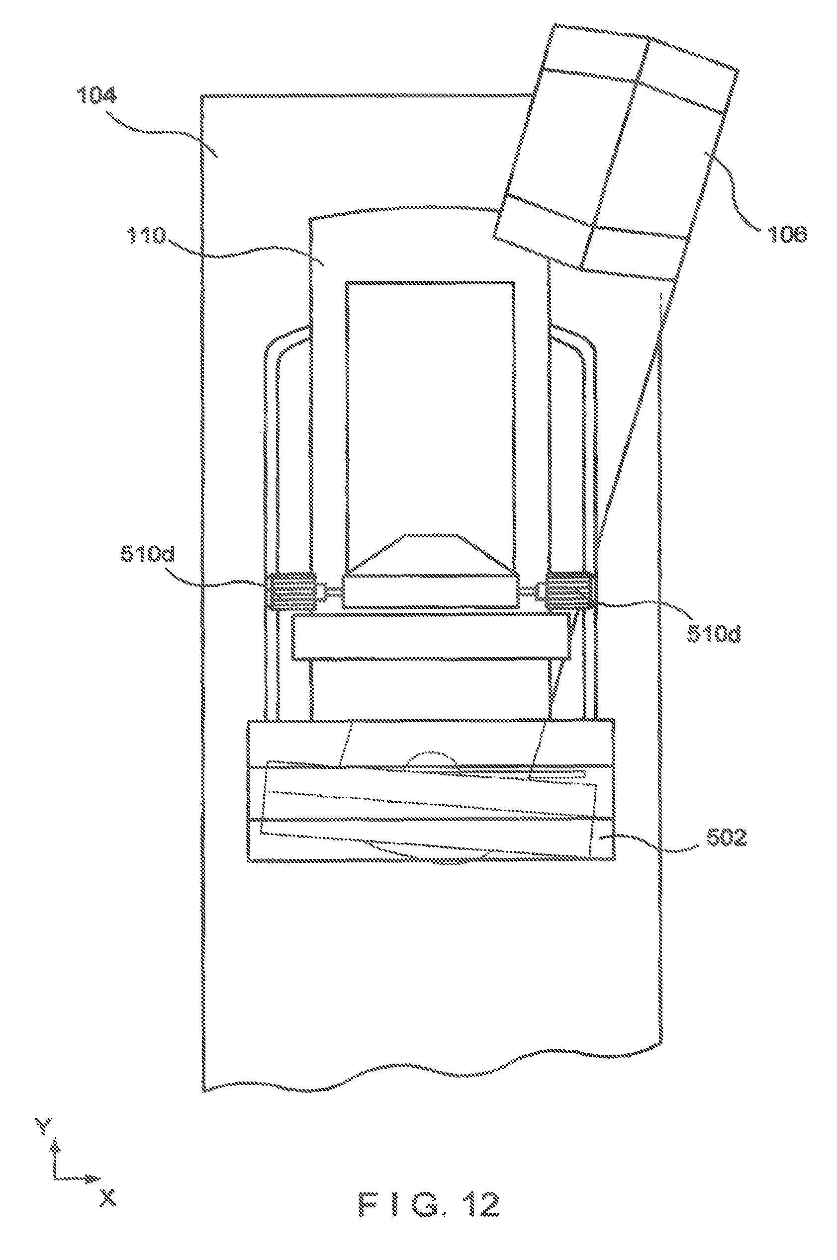
FIG. 1 is a perspective view of a gantry and an acquisition workstation in accordance with an example of the disclosed system.
FIG. 2 is an enlarged view of a portion of the system of FIG. 1, with a tube arm assembly in a rotated position.
FIG. 3 is a front elevation of the apparatus of FIG. 2.
FIG. 4 is side view of a gantry with a biopsy station and a spacer with schematic illustration of other mechanisms.
FIG. 5 is an enlarged view of a portion of FIG. 1.
FIG. 6 is a block diagram of the disclosed system when connected to other systems.
FIG. 7 is a flow chart illustrating a general work flow for the disclosed system.
FIG. 8 is a flow chart illustrating one of several examples of work flow for a standard mammography mode.
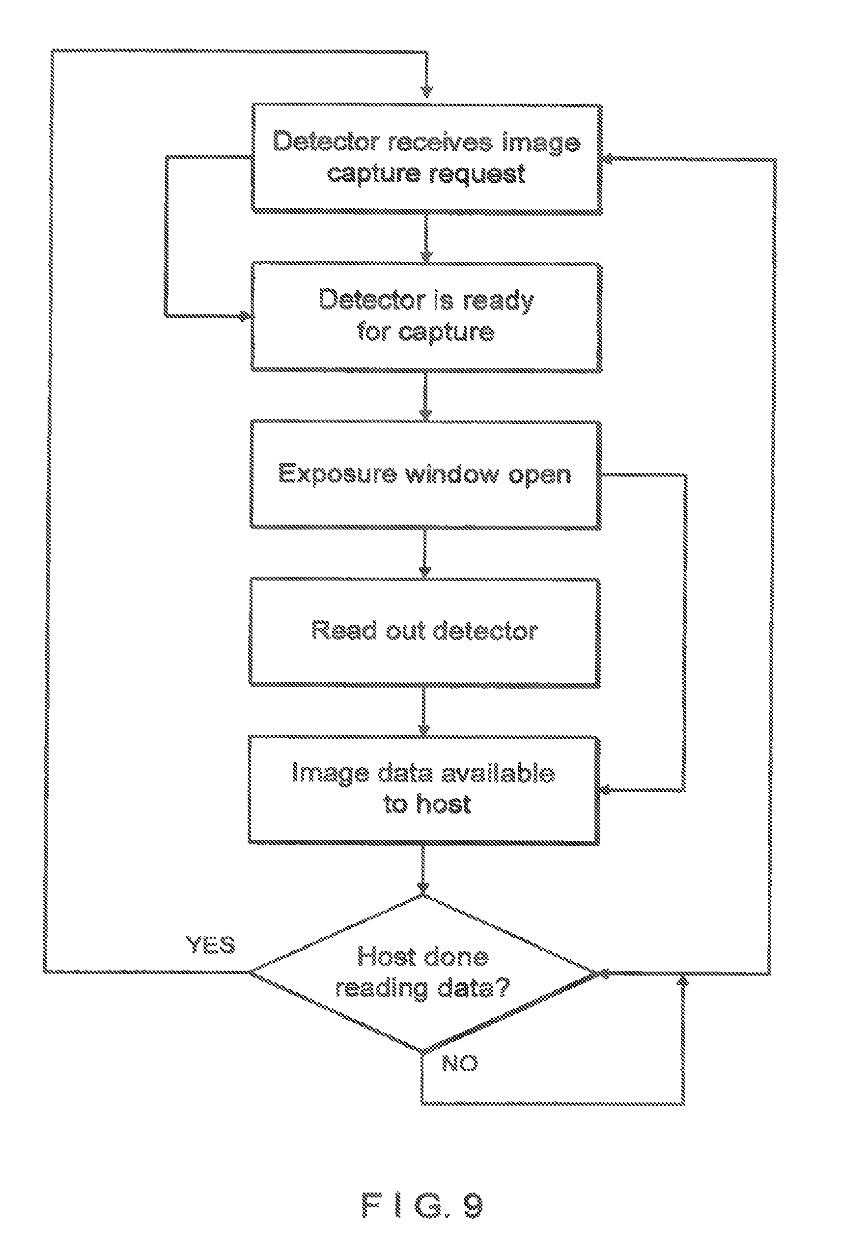
FIG. 9 is a flow chart illustrating one of several examples of work flow for an image detector subsystem in the standard mammography mode.
FIG. 10 is a perspective view of the structure of FIG. 4.
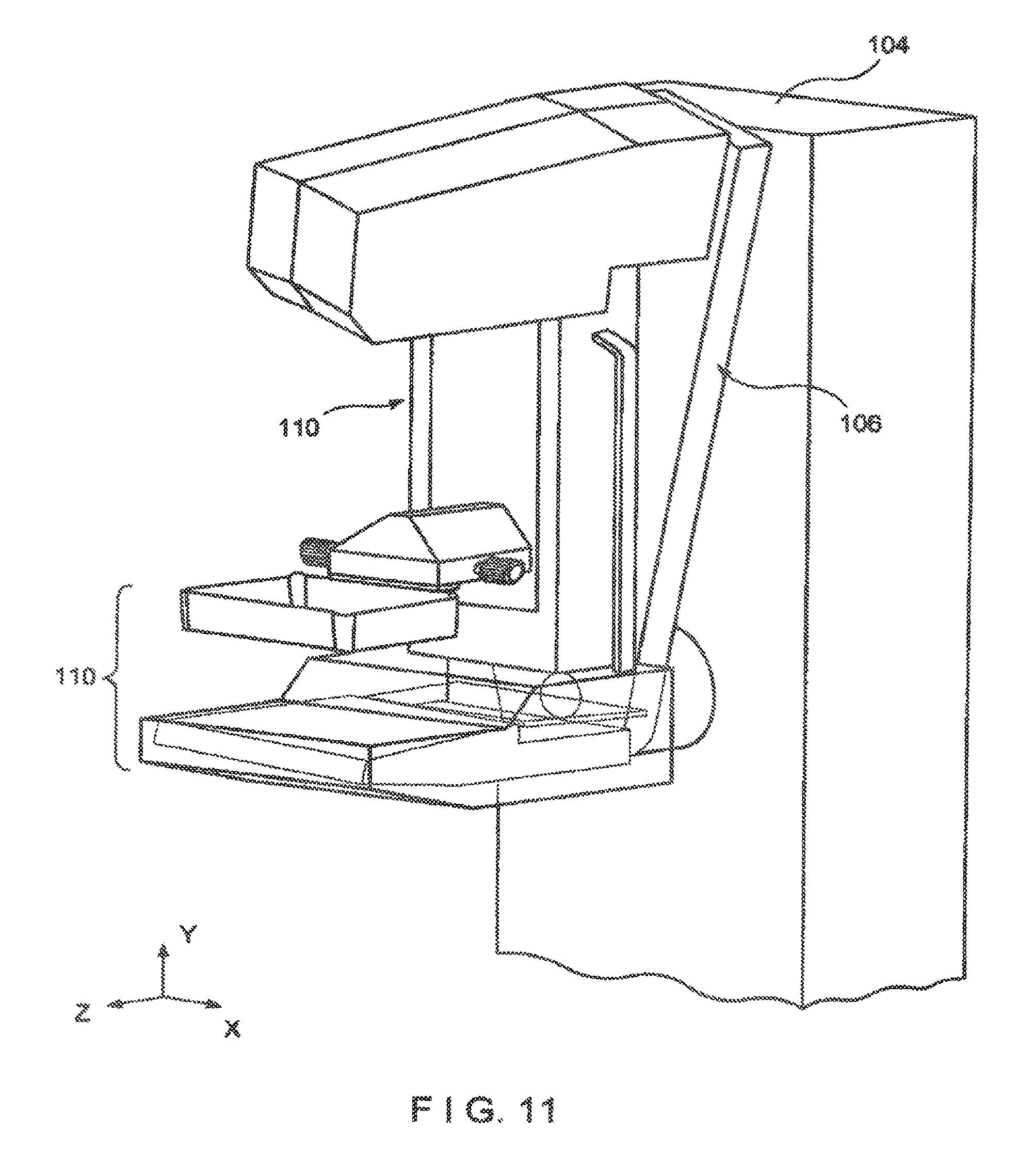
FIG. 11 is similar to FIG. 2 but shows a tube arm assembly angled differently.
FIG. 12 is a front elevation of the structure of FIG. 11.
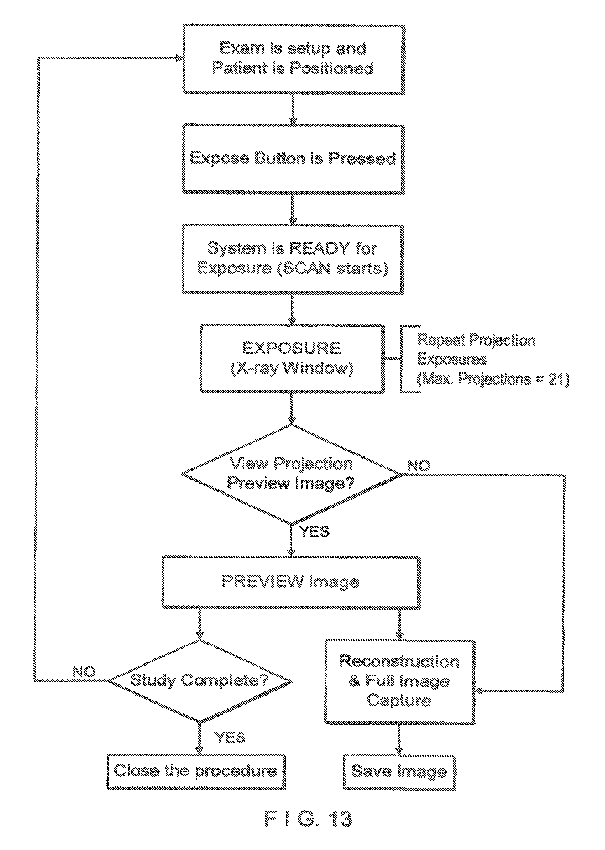
FIG. 13 is a flow chart illustrating one of several examples of work flow for a tomosynthesis mode.
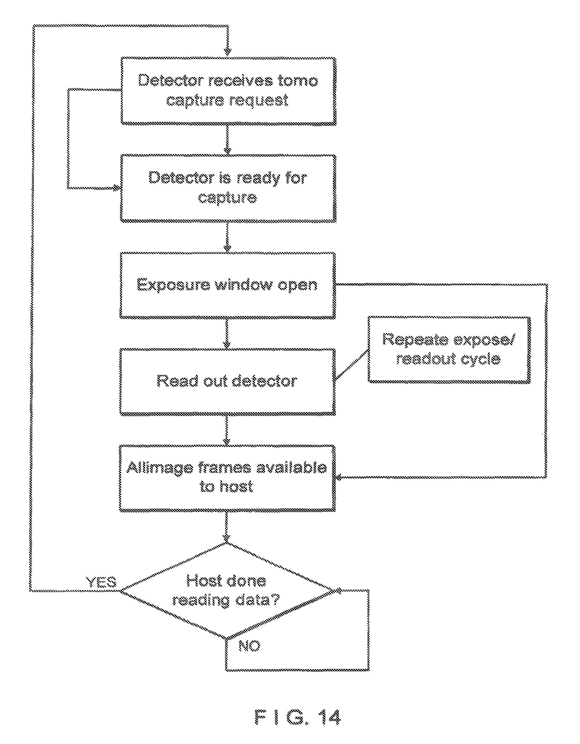
FIG. 14 is a flow chart illustrating one of several examples of work flow for an image detector subsystem in the tomosynthesis mode.
FIG. 15 is a few chart illustrating one of several examples of work flow for a combination mode.
FIG. 16 is a flow chart illustrating one of several examples of work flow for an image detector subsystem in the combination mode.
FIG. 17 is an enlarged side view of a structure for removably mounting a breast compression paddle.
DETAILED DESCRIPTION OF PREFERRED EMBODIMENTS
In describing examples and preferred embodiments illustrated in the drawings, specific terminology is employed for the sake of clarity. However, the disclosure of this patent specification is not intended to be limited to the specific terminology so selected and it is to be understood that each specific element includes all technical equivalents that operate in a similar manner.
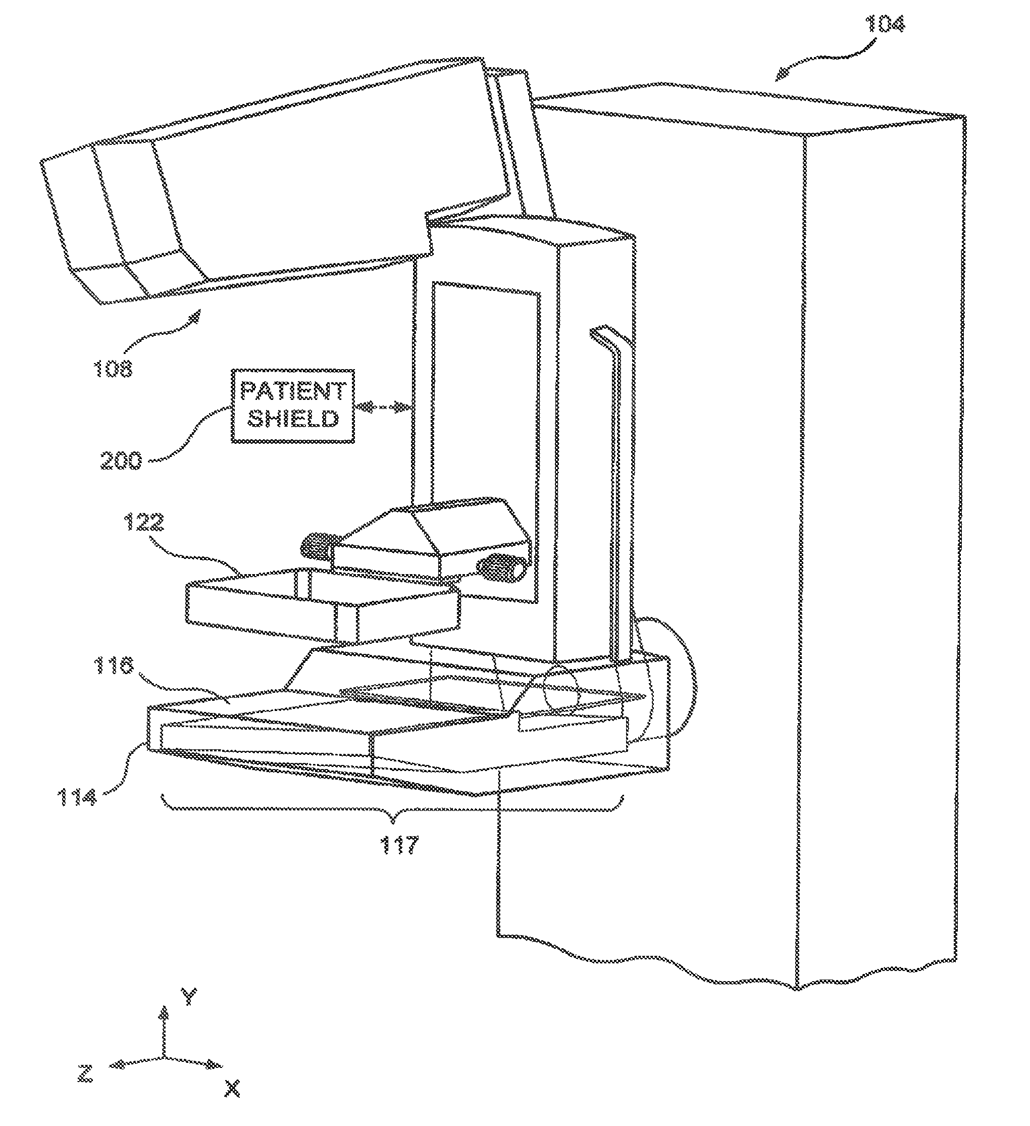
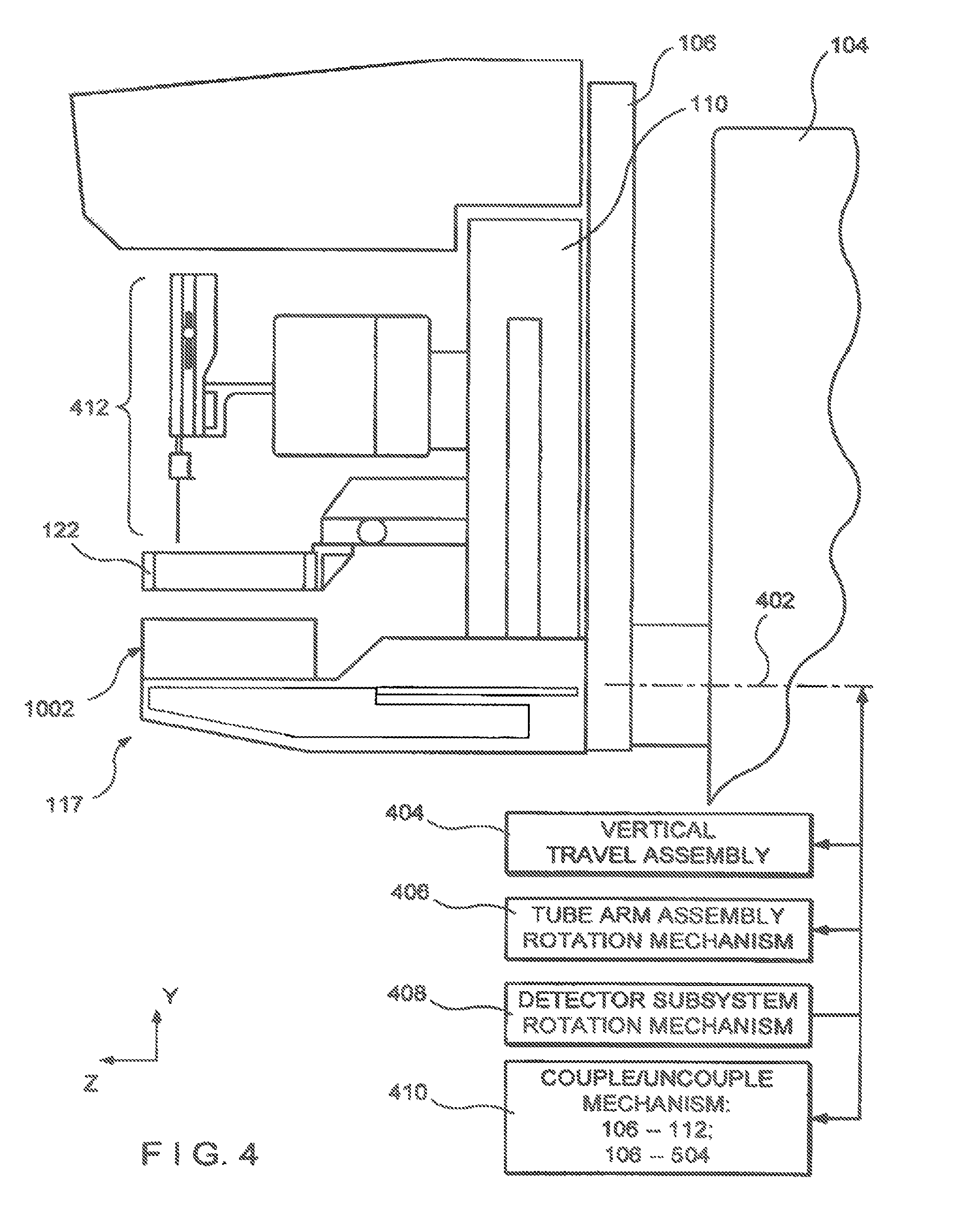
FIG. 1-6 illustrate a non-limiting example of a multi-mode mammography/tomosynthesis system comprising a gantry 100 and a data acquisition work-station 102. Gantry 100 includes a housing 104 supporting a tube arm assembly 106 rotatably mounted thereon to pivot about a horizontal axis 402 (FIG. 4) and carrying an x-ray tube assembly 108. X-ray tube assembly 108 includes (1) an x-ray tube generating x-ray energy in a selected range, such as 20-50 kV, at mAs such as in the range 3-400 mAs, with focal spots such as a nominal size 0.3 mm large spot and nominal size 0.1 mm small spot (2) supports for multiple filters such as molybdenum, rhodium, aluminum, copper, and tin filters, and (3) so adjustable collimation assembly selectively collimating the x-ray beam from the focal spot in a range such as from 7.times.8 cm to 24.times.29 when measured at the image plane of an x-ray image receptor included in the system, at a maximum source-image distance such as 75 cm. Also mounted on housing 104, for rotation about the same axis 402, is a compression arm assembly 110 that comprises a compression plate 122 and a receptor housing 114 having an upper surface 116 serving as a breast plate and enclosing a detector subsystem system 117 comprising a first panel x-ray receptor 502 (FIG. 5), a retractable anti-scatter grid 504 and a mechanism 506 for driving and retracting anti-scatter grid 504. Housing 104 also encloses the following components schematically illustrated in FIG. 4: a vertical travel assembly 404 for moving tube arm assembly 106 and compression arm assembly 110 up and down to accommodate a particular patient or imaging position, a tube arm assembly rotation mechanism 400 to rotate tube arm assembly 106 about axis 402 for different imaging positions, a detector subsystem rotation mechanism 408 for rotating components of detector subsystem 117 (such as x-ray receptor 502) about axis 402 to accommodate different operations modes, and couple/uncouple mechanism 410 to selectively couple or uncouple tube arm assembly 106 and compression arm assembly 110 to and from each other, and tube arm assembly 106 and detector subsystem 117 to and from each other. Housing 104 also encloses suitable motors and electrical and mechanical components and connections to implement the functions discussed here. A patient shield 200, schematically illustrated in FIG. 2, can be secured to compression arm assembly 110 to provide a mechanical interlock against patient contact with the rotating x-ray tube arm assembly 106. Work-station 102 comprises components similar to those in the Selenia.TM. mammography system, including a display screen (typically a flat panel display that may include touch-screen functionality), user interlace devices such as a keyboard, possibly a touch-screen, and a mouse or trackball, and various switches and indicator lights and/or displays. Work-station 102 also includes compute facilities similar to those of the Selenia.TM. system (but adapted through hardware, firmware and software differences) for controlling gantry 100 and for processing, storing and displaying data received from gantry 100. A power generation facility for x-ray tube assembly 108 may be included in housing 104 or in work-station 102. A power source 118 powers work-station 102. Gantry 100 and work-station 102 exchange data and controls over a schematically illustrated connection 120.
As illustrated in FIG. 6, additional storage facilities 602 can be connected to work-station 102, such as one or more optical disc drives for storing information such as images and/or for providing information to work-station 102 such as previously obtained images and software, or a local printer (not shown). In addition, the disclosed system can be connected to a hospital or local area or other network 604, and through the network to other systems such as a soft copy workstation 606, a CAD (Computer Aided Detection) station 608 for computer-processing mammography and/or tomosynthesis images to identify likely abnormalities, an image printer 610 for printing images, a technologist workstation 612, other imaging systems 614 such as other mammography systems or systems for other modalities for exchange of images and/or other information, and to a PACS (Picture Archiving) systems 616 for archiving images and other information and/or retrieving images and other information.
The illustrated system has several modes of operation. An example of typical workflow generally applicable for each mode is illustrated is FIG. 7, and several examples of operational modes are discussed below. Of course, this is only one example and workflow steps may be arranged differently. In all modes, the operator can perform x-ray exposure using manual setting of technic factors such as mA and mSec, or can use an automatic exposure control as known in the art to set the exposure time, kV and filter modes for an image, for example by using a short, low-x-ray dose pre-exposure. Workstation 102 is set up to record the exposure technic information and associate it with the breast image for later review.
In standard mammography mode, typically used for screening mammography, tube arm assembly 106 and compression arm assembly 110 are coupled and locked together by 410 in a relative position such as seen in FIG. 1, such that an x-ray beam from x-ray tube assembly 108 illuminate x-ray receptor 502 when the patient's breast is compressed by compression devise 112. In this mode, the system operates in a manner similar to said Selenia.TM. system to take a mammogram. Vertical travel assembly 404 and tube arm rotation mechanism 406 can make vertical adjustments to accommodate a patient, and can rotate tube arm assembly 106 and compression arm assembly 118 together as a unit about axis 402 for different image orientations such as for CC and for MLO images. For example, tube arm assembly 106 and compression arm assembly 110 can rotate between (-195.degree.) and (+150.degree.) about axis 402. As in the Selenia.TM. system, compression device 112 includes a compression paddle 122 that can move laterally, in a direction along the chest wall of a patient, to adjust for different imaging orientations. However, as described further below, the mechanism for supporting and moving compression paddle 122 is different. Typically, anti-scatter grid 504 is over x-ray receptor 502 in the standard mammography mode to reduce the effect of x-ray scatter. FIG. 8 illustrates a typical workflow for an exposure in standard mammography mode, and FIG. 10 illustrates an example of the operation of detector subsystem 117 in standard mammography. Of course, these are only examples; other workflow steps or orders of steps can be used instead.
In a diagnostic mode, the patient's breast can be spaced from upper surface 116, for example by an x-ray translucent spacer gantry 1002 (FIG. 10), with the system otherwise similar to FIG. 1, for a magnification of up to 1.8, for example. In this mode, as in standard mammography, tube arm assembly 106 and compression arm assembly 110 are locked to each other and can move up or down and rotate about axis 402 for different image orientation. A different spacer 1002 can be used for a different degree of magnification. Also, differently shaped or dimensioned compression paddles 122 can be used for different breast compression effects. The x-ray tube in x-ray tube assembly 108 can be set to a smaller focal spot size to improve a diagnostic image. In this mode, anti-scatter grid 504 typically is retracted when magnification is used such that grid 504 is completely out of the image. The user can elect not to use a spacer 1002 in diagnostic imaging, in which case anti-scatter grid 504 can be used over the entire image.
In a dynamic imaging mode, a number of breast images are taken while the patient's breast remains compressed. In one technique, an agent such as iodine is infected into the patient and after a suitable waiting time such as about one minute for a maximum uptake, two images breast are taken in rapid succession, for example one at an x-ray energy just above the K-edge of iodine and one at an energy just below the K-edge. Alternatively, a succession of breast images can be taken at a single x-ray energy band or bands just above and below the K-edge or at another x-ray energy range, to track the uptake of agent over time. Another technique adds taking a baseline breast image before or soon after injecting the agent and using it together with later breast images to generate subtraction images that provide better visualization of anatomy that may be of interest. Still another dynamic imaging mode technique comprises injecting a contrast agent and taking a succession of images over a period such as 5-7 minutes, for example one image every minute, and processing the image data to generate for each pixel, or at least for each pixel of interest, a histogram of the change in the pixel value, to thereby use the manner in which pixel values change to differential abnormal tissue. For this mode, work-station 102 can store preset data that commands gantry 100 and work-station 102 to take a desired sequence of images for the dynamic mode technique selected by the operator, such that the command data sets the appropriate parameters such as x-ray energy, dose, timing of images, etc. Alternatively, such processing to assess changes in pixel values can be done for a region of interest rather than over individual pixels, to produce information such as a measure of changes in the average pixel values in the region of interest.
In tomosynthesis mode, tube arm assembly 106 and compression arm assembly 110 are decoupled by unit 410 such that compression arm assembly 110 stays in one position, compressing the patient's breast, while tube arm assembly 106 rotates about axis 402, for example between the position illustrated in FIG. 2 to that illustrated in FIG. 11, or .+-.15.degree. relative to compression arm assembly 110. Tomosynthesis can be carried out for different image orientations, so that compression arm assembly 110 can be rotated about axis 402 (alone or together with assembly 106) for a desired image orientation and locked in place, and then tube arm assembly 106 can be rotated relative to that position of compression arm assembly 110 for tomosynthesis imaging over .+-.15.degree. or some other desired angular range. In one example, 11 images are taken during an angular sweep of tube arm assembly 106, one every approximately 3.degree.. However, a different number of images can be taken, for example up to 21 during a single sweep. For tomosynthesis images, the x-ray tube in x-ray tube assembly 108 continuously rotates and the x-ray tube is pulsed for each image, for example, for x-ray energy pulses each lasting approximately 100 mSec, although pulses of different duration can be selected. Alternatively, the rotational motion can stop for taking each image, or continuous motion without pulsing can be used (and the timing of data measurements relied to define pixel values). As seen in FIGS. 2, 3, 5, 11 and 12, in this mode mechanism 506 fully retracts anti-scatter grid 504 away front x-ray receptor 502 so grid 504 is out of the image. Also as seen in these FIGS., while the breast remains immobilized in compression arm assembly 110 during the angular sweep of tube arm assembly 106, x-ray receptor 502 rocks within receptor housing 114. In this rocking motion, controlled by unit 401 (FIG. 4), a line normal to the image face of x-ray receptor 502 may keep pointing to the focal spot of the x-ray tube in x-ray tube assembly 108. Alternatively, the rotation of tube arm assembly 106 and rocking of x-ray receptor 502 can be through different angles; for example, tube arm assembly 106 can rotate through 15.degree. while x-ray receptor 502 rocks through 5.degree., i.e., the rocking angle can be amount one-third that of assembly 108. Synchronous rotation of tube arm assembly 106 and rocking of x-ray receptor 502 can be achieved by controlling separate motors for each or, alternatively, through using a motor to drive tube arm assembly 106 and a mechanical coupling between the rotation of tube arm assembly 106 and rocking of x-ray receptor 502. Image data can be obtained and processed into tomosynthesis images for display and/or storage as described in the material incorporated by reference, for example in co-pending patent application Ser. No. 10/723,486 or in U.S. Provisional Application No. 60/621,516, filed Nov. 15, 2004. FIG. 13 illustrates a typical workflow for tomosynthesis mode operation, and FIG. 14 illustrates an example of the operation of detector subsystem 117 in that mode. Again, these are only examples, and other steps or orders of steps can be used instead.
In a combination mode, during a single compression of the patient's breast the system takes a conventional mammogram and tomosynthesis images. In this mode, while the breast remains compressed in compression arm assembly 110, (1) tube arm assembly 106 sweeps and x-ray receptor 502 rocks, each through an appropriate angle, and exposures are taken for tomosynthesis images, and (2) a standard mammogram is taken. The standard mammogram can be taken at a 0.degree. relative angle between tube arm assembly 106 and a normal to the imaging plane of x-ray receptor 502, and can be taken before or after the tomosynthesis images are taken or between the taking of two successive tomosynthesis images. Typically, each tomosynthesis image utilizes substantially lower x-ray dose than the standard mammogram. For example, the total x-ray dosage for tomosynthesis imaging in one sweep of tube arm assembly 106 can be approximately the same as that for a single standard mammogram, or up to approximately three times that dosage. The relationship between the two dosages can be user-selected. FIG. 15 illustrates an example of workflow for the combination mode, and FIG. 16 illustrates an example of the operation of detector subsystem 117 in that mode. Again, these are examples, and different steps or orders of steps can be used instead. For example, a preferred approach may be to take the standard mammogram first, then move arm 106 to one end of its rotational range for tomosynthesis and take the tomosynthesis images. The order in which the two types of images are taken may be optimized such that the overall imaging time is minimized, and an order that achieves such minimization can be the preferred order. The exposure (tube current mA, tube voltage kVp, and exposure length msec) techniques for the standard mammogram and the tomosynthesis exposures can be set manually, or by using automatic methods. If the standard mammogram is taken first, its exposure techniques can be used to set an optimal technique for the subsequent tomosynthesis images, and vice versa. The exposure technique can be modified dynamically, if the software senses that the signal reaching the image receptor is either too low or too high and adjust subsequent exposures as needed.
In a stereotactic mode, during a single compression of the patient's breast at least two images of taken, for example one at (+15).degree. angle and at (-15.degree.) angle of tube arm assembly 106 relative to compression arm assembly 110, although other angles can be used and more images can be taken. X-ray receptor 502 can remain in place for this procedure, or can be rocked through a selected angle, for example through an angle sufficient to maintain the same orientation of the imaging surface of receptor relative to tube arm assembly 106. A spacer 1002 can be used for magnification. If x-ray receptor 502 remains in plane despite rotation of arm 106, or if spacer 1002 is used, anti-scatter grid 504 is fully retracted; if x-ray receptor 502 maintains its orientation relative to tube arm assembly 106 and not spacer 1002 is used, anti-scatter grid 504 need not be retracted. As is known in the art, the two or more images can be used to identify the location of a lesion, so that needle biopsy can be used, for example with an upright needle biopsy station 412 (FIG. 4) in a manner similar to that used with the commercially available Selenia.TM. system and StereoLoc II.TM.. A compression paddle 122 appropriate for needle biopsy typically is used when taking the stereotactic images. Alternatively, some or all of the images taken in the tomosynthesis mode and/or in the combined mode can be used to identify the location of a lesion for biopsy, in which case a compression paddle 122 appropriate for the purpose typically is used when taking the images.
In needle localization mode, x-ray images can be taken after a biopsy or other needle is inserted into the compressed breast. For this purpose, imaging such as in the stereotactic mode, the tomosynthesis mode, or the combined mode can be used.
In the disclosed system, compression paddle 122 is movable laterally, as generally described in U.S. Patent Application Publication No. 2005/0063509 A1, hereby incorporated by reference herein. In addition, compression paddle 122 can pivot about an axis along the patient's chest wall to conform the breast shape in certain procedures, as discussed in said U.S. Pat. No. 5,786,327. However, in the system of this patent specification compression paddle 122 is mounted differently and moves in a different manner.
As illustrated in FIGS. 5 and 17, compression paddle 122 is removably mounted to a support 510 that moves up and down compression arm assembly 110 as needed for breast compression. To mount compression puddle 122 onto 510, a projection compression paddle 122a of the paddle engages a projection 510a of the support, and a projection 122b of the paddle latches onto projection 510b of the support. Projection 510a is spring-loaded, such as by a spring schematically illustrates at 510c to allow for pivoting compression paddle 122 about an axis where it latches onto 510, as illustrated by arrow A, for better conformance with the compressed breast in some imaging protocols. Other imaging protocols may require compression paddle 122 not to pivot, in which case projection 310a is locked in place by a locking mechanism in 510 (not shows) to keep compression paddle 122 in place relative to support 510. The locking mechanism can be manually set to a lock position, and manually unlocked by the operator. Alternatively, the locking mechanism can be controlled through an operator input at gantry 100 or work-station 102. A sensing mechanism can be included to sense whether compression paddle 122 is locked against pivoting, to provide information that work-station 102 can use for setting imaging protocols such as for automated breast compression and automated exposure methods. Two knobs 510d, one on each lateral side of support 510, can be manually rotated to move projection 510b and thus compression paddle 122 laterally such that it compress a breast that is not centered laterally on upper surface 116, for example for MLO imaging. Each knob 510d can operate a mechanism such as an endless screw rotating in a nut secured to projection 510b. Alternatively, or in addition, projection 510b and thus compression paddle 122 can be driven laterally by a motor, under control of operator switches or other interface at gantry 100 or at work-station 102, or automatically positioned laterally under computer control.
Importantly, compassion paddle 122 is driven for lateral movement by components that are a part of support 510. Thus, compression paddle 122 can be simple structure, and can even be disposable, with a new one used for each patient or for only a few patients. This can simplify and reduce the cost of using the system, because an imaging facility usually stocks a number of different paddles for different purposes. If the lateral movement mechanism is integral with a compression paddle, the paddle assembly is considerably larger, heavier and more expensive. But with a compression paddle 122 that relies for lateral movement on support 510, and is easily mounted by hand and without tools to support 510, by sliding compression paddle 122a into projection 510a and latching projection paddle 122b onto projection 510b, and is easily removed by reversing the process, the expense of keeping a number of different compression paddles in stock or replacing paddles with new ones is greatly reduced, as are the time and convenience when changing from one type of compression paddle to another. Compression paddle 122 can include a bar code that is automatically read by a bar code reader in support 510, to keep work-station 102 informed of the paddle currently mounted to support 510, for use in automating imaging protocols. For example, the bar code information can be checked to ensure through computer processing that the type of paddle that is currently mounted on support 510 matches the imaging that will be commanded, and the information from the sensor for whether compression paddle 122 is locked in non-tilting mode can be used to automatically make adjustments for compression height to ensure accurate automatic x-ray exposure operation. Further, the bar code information identifying the paddle can be used to automatically set collimation in x-ray tube assembly 108 so that the x-ray beam matches the size and shape of the currently installed compression paddle 122.
The above specific examples and embodiments are illustrative, and many variations can be introduced on these examples and embodiments without departing from the spirit of the disclosure or from the scope of the appended claims. For example, elements and/or features of different illustrative embodiments may be combined with each other and/or substituted for each other within the scope of this disclosure and appended claims.
This application claims the benefit of U.S. provisional application Ser. No. 60/631,296, filed Nov. 26, 2004 and entitled "INTEGRATED MULTI-MODE MAMMOGRAPHY/TOMOSYNTHESIS X-RAY SYSTEM AND METHOD", the entire contents of which are incorporated herein by reference.
* * * * *
References
D00000
D00001
D00002
D00003
D00004
D00005
D00006
D00007
D00008
D00009
D00010
D00011
D00012
D00013
D00014
D00015

D00016

XML
uspto.report is an independent third-party trademark research tool that is not affiliated, endorsed, or sponsored by the United States Patent and Trademark Office (USPTO) or any other governmental organization. The information provided by uspto.report is based on publicly available data at the time of writing and is intended for informational purposes only.
While we strive to provide accurate and up-to-date information, we do not guarantee the accuracy, completeness, reliability, or suitability of the information displayed on this site. The use of this site is at your own risk. Any reliance you place on such information is therefore strictly at your own risk.
All official trademark data, including owner information, should be verified by visiting the official USPTO website at www.uspto.gov. This site is not intended to replace professional legal advice and should not be used as a substitute for consulting with a legal professional who is knowledgeable about trademark law.