Container
Schennum , et al. Fe
U.S. patent number 10,194,689 [Application Number 14/895,446] was granted by the patent office on 2019-02-05 for container. This patent grant is currently assigned to NICOVENTURES HOLDINGS LIMITED. The grantee listed for this patent is NICOVENTURES HOLDINGS LIMITED. Invention is credited to Jeremy Aaron Abel, Thomas Michael McKeon, Steven Michael Schennum.


| United States Patent | 10,194,689 |
| Schennum , et al. | February 5, 2019 |
Container
Abstract
A container for an electronic nicotine delivery system. The container has a body having a pair of end walls spaced from each other by a base wall and the body also includes a recess extending between the end walls to receive an electronic nicotine delivery system. A lid is pivotally attached to the body for rotation between open and closed positions about an axis parallel to a longitudinal axis of an electronic nicotine delivery system received in the recess.
| Inventors: | Schennum; Steven Michael (Plainfield, IL), McKeon; Thomas Michael (Wheaton, IL), Abel; Jeremy Aaron (Oswego, IL) | ||||||||||
|---|---|---|---|---|---|---|---|---|---|---|---|
| Applicant: |
|
||||||||||
| Assignee: | NICOVENTURES HOLDINGS LIMITED
(London, GB) |
||||||||||
| Family ID: | 51033230 | ||||||||||
| Appl. No.: | 14/895,446 | ||||||||||
| Filed: | June 3, 2014 | ||||||||||
| PCT Filed: | June 03, 2014 | ||||||||||
| PCT No.: | PCT/GB2014/051688 | ||||||||||
| 371(c)(1),(2),(4) Date: | December 02, 2015 | ||||||||||
| PCT Pub. No.: | WO2014/195688 | ||||||||||
| PCT Pub. Date: | December 11, 2014 |
Prior Publication Data
| Document Identifier | Publication Date | |
|---|---|---|
| US 20160101909 A1 | Apr 14, 2016 | |
Related U.S. Patent Documents
| Application Number | Filing Date | Patent Number | Issue Date | ||
|---|---|---|---|---|---|
| 61830924 | Jun 4, 2013 | ||||
| Current U.S. Class: | 1/1 |
| Current CPC Class: | A24F 15/12 (20130101); B65D 43/16 (20130101); B65D 85/70 (20130101); A24F 15/14 (20130101); B65D 43/22 (20130101); B65D 25/10 (20130101); A24F 47/002 (20130101); A45C 13/007 (20130101); A24F 47/008 (20130101); A45C 13/00 (20130101) |
| Current International Class: | A24F 15/14 (20060101); A24F 47/00 (20060101); A24F 15/12 (20060101); A45C 13/00 (20060101); B65D 25/10 (20060101); B65D 85/00 (20060101); B65D 43/22 (20060101); B65D 43/16 (20060101) |
References Cited [Referenced By]
U.S. Patent Documents
| 228598 | June 1880 | Buckley |
| 353327 | November 1886 | Randolph |
| 576653 | February 1897 | Bowlby |
| 595070 | December 1897 | Oldenbusch |
| 744074 | November 1903 | Hiering |
| 799844 | September 1905 | Fuller |
| 885374 | April 1908 | Pohlig |
| 1163183 | December 1915 | Stoll |
| 1174406 | March 1916 | Gillan |
| D53386 | May 1919 | Thomas |
| 1436157 | November 1922 | Fazio |
| 1512098 | October 1924 | Hough |
| 1807936 | June 1931 | Saunders |
| 1815069 | July 1931 | Petro |
| 1923560 | August 1933 | Whittaker |
| 1934629 | November 1933 | Reilly |
| 1937120 | November 1933 | Lagerholm |
| 1937987 | December 1933 | Sexton |
| 2262318 | November 1941 | Fox |
| 2411946 | December 1946 | Vogel |
| 2467923 | April 1949 | Allen |
| 2483304 | September 1949 | Vogel |
| 2513672 | July 1950 | Pino |
| 2522952 | September 1950 | Krohn |
| 2544501 | March 1951 | Johnson |
| 2658368 | November 1953 | Siegel |
| 2782910 | February 1957 | Keibow |
| 3165225 | January 1965 | Reitzel |
| 3722742 | March 1973 | Wertz |
| 3743136 | July 1973 | Chambers |
| 3861523 | January 1975 | Fountain |
| 3863803 | February 1975 | Valcic |
| 4190412 | February 1980 | Tokai |
| 4214658 | July 1980 | Crow |
| D279508 | July 1985 | Bauer et al. |
| 4733794 | March 1988 | Kent |
| 4753383 | June 1988 | Focke |
| 4793478 | December 1988 | Tudor |
| 4923059 | May 1990 | Evers |
| 4961438 | October 1990 | Korte |
| 5044550 | September 1991 | Lamm |
| D322687 | December 1991 | Tschudin |
| D346878 | May 1994 | Gee et al. |
| 5353956 | October 1994 | Wilson |
| 5448317 | September 1995 | Tamway |
| D392069 | March 1998 | Rowland |
| D404201 | January 1999 | Wennerstrom |
| 5896984 | April 1999 | Focke |
| 5938017 | August 1999 | Wik |
| D414892 | October 1999 | Chen |
| 5967312 | October 1999 | Jacobs |
| 5996783 | December 1999 | Herchelroth |
| D432263 | October 2000 | Abdullah |
| D434217 | November 2000 | Packard |
| D434979 | December 2000 | Liu |
| D436725 | January 2001 | Rogers |
| D438003 | February 2001 | Minagawa |
| D441133 | April 2001 | Emery |
| D449521 | October 2001 | Pinkus et al. |
| 6321757 | November 2001 | McCutcheon |
| 6446793 | September 2002 | Layshock |
| D466012 | November 2002 | Baker |
| D470765 | February 2003 | Baker |
| D471804 | March 2003 | Staples |
| D472012 | March 2003 | South |
| 6530495 | March 2003 | Joseph |
| 6561391 | May 2003 | Baker |
| 6715605 | April 2004 | Manservigi |
| 6726006 | April 2004 | Funderburk |
| 6736143 | May 2004 | Rennecampe |
| D493617 | August 2004 | Armato |
| D509732 | September 2005 | Staples |
| D545186 | June 2007 | Liebe |
| D549573 | August 2007 | Liebe |
| D550455 | September 2007 | Barnhart |
| D566329 | April 2008 | Bagaric et al. |
| D566890 | April 2008 | Bagaric et al. |
| 7389878 | June 2008 | Torrico |
| D573889 | July 2008 | Short |
| D575451 | August 2008 | Jones |
| 7455176 | November 2008 | Focke |
| 7565969 | July 2009 | Wen-Tan |
| D606854 | December 2009 | Greenhalgh |
| D610983 | March 2010 | Wai |
| D611806 | March 2010 | Bried |
| D613903 | April 2010 | Wu |
| D613904 | April 2010 | Wu |
| D616753 | June 2010 | Beam |
| D628469 | December 2010 | Taylor |
| D631838 | February 2011 | Cheng |
| D636257 | April 2011 | Bougoulas |
| D649658 | November 2011 | Belfrance |
| D650738 | December 2011 | Leung |
| 8113343 | February 2012 | Aakerlind |
| D656094 | March 2012 | Wu |
| D661016 | May 2012 | Borges |
| D671677 | November 2012 | Wu |
| D671678 | November 2012 | Wu |
| 8307834 | November 2012 | Palmerino |
| D672642 | December 2012 | Supranowicz |
| D674539 | January 2013 | Wu |
| 8448783 | May 2013 | Vecchi |
| D693055 | October 2013 | Manca et al. |
| 8602210 | December 2013 | Milner |
| D700397 | February 2014 | Manca et al. |
| 8794245 | August 2014 | Scatterday |
| D715760 | October 2014 | Kim et al. |
| D716267 | October 2014 | Kim et al. |
| 8910783 | December 2014 | Liu |
| D720884 | January 2015 | Liu |
| D723738 | March 2015 | Liu |
| D736460 | August 2015 | McKeon et al. |
| D737507 | August 2015 | Liu |
| 2004/0056651 | March 2004 | Daniele |
| 2005/0087460 | April 2005 | Bruhm |
| 2005/0224375 | October 2005 | Focke |
| 2007/0193895 | August 2007 | Weiss |
| 2007/0267032 | November 2007 | Shan |
| 2008/0083627 | April 2008 | Hamm |
| 2008/0223382 | September 2008 | Zeanah |
| 2009/0223841 | September 2009 | Mack, Jr. |
| 2009/0266837 | October 2009 | Gelardi |
| 2009/0288966 | November 2009 | Minarelli |
| 2010/0313901 | December 2010 | Fernando |
| 2011/0011396 | January 2011 | Fang |
| 2011/0180433 | July 2011 | Rennecampe |
| 2011/0226236 | September 2011 | Buchberger |
| 2011/0303231 | December 2011 | Li et al. |
| 2012/0103842 | May 2012 | Koester |
| 2012/0145169 | June 2012 | Wu |
| 2012/0199146 | August 2012 | Marangos |
| 2012/0227752 | September 2012 | Alelov |
| 2012/0227753 | September 2012 | Newton |
| 2013/0098786 | April 2013 | Collins |
| 2013/0192615 | August 2013 | Tucker |
| 2013/0284192 | October 2013 | Peleg |
| 2013/0340779 | December 2013 | Liu |
| 2013/0341218 | December 2013 | Liu |
| 2013/0342157 | December 2013 | Liu |
| 2014/0007892 | January 2014 | Liu |
| 2014/0020697 | January 2014 | Liu |
| 2014/0060528 | March 2014 | Liu |
| 2014/0060555 | March 2014 | Chang |
| 2014/0196731 | July 2014 | Scatterday |
| 2014/0209105 | July 2014 | Sears |
| 2014/0238423 | August 2014 | Tucker |
| 2014/0238424 | August 2014 | Macko |
| 2014/0261490 | September 2014 | Kane |
| 2014/0270730 | September 2014 | DePiano |
| 2016/0101909 | April 2016 | Schennum |
| 2016/0106155 | April 2016 | Reevell |
| 2016/0120218 | May 2016 | Schennum et al. |
| 6402132 | Jul 1986 | BR | |||
| 199400288 | Aug 1995 | CL | |||
| 1329567 | Jan 2002 | CN | |||
| 2485265 | Apr 2002 | CN | |||
| 2660914 | Dec 2004 | CN | |||
| 2904674 | May 2007 | CN | |||
| 101115901 | Jan 2008 | CN | |||
| 201023852 | Feb 2008 | CN | |||
| 201240612 | May 2009 | CN | |||
| 201370099 | Dec 2009 | CN | |||
| 201430913 | Mar 2010 | CN | |||
| 201592850 | Sep 2010 | CN | |||
| 101878958 | Nov 2010 | CN | |||
| 201657770 | Dec 2010 | CN | |||
| 201830900 | May 2011 | CN | |||
| 102264420 | Nov 2011 | CN | |||
| 202122096 | Jan 2012 | CN | |||
| 201860753 | Jun 2012 | CN | |||
| 594585 | Mar 1934 | DE | |||
| 2940797 | Apr 1981 | DE | |||
| 2940797 | Apr 1981 | DE | |||
| 202013100606 | Feb 2013 | DE | |||
| 202013100606 | Feb 2013 | DE | |||
| 1820748 | Aug 2007 | EP | |||
| 225233 | Nov 2010 | EP | |||
| 472030 | Nov 1914 | FR | |||
| 1292446 | May 1962 | FR | |||
| 1292446 | May 1962 | FR | |||
| 190930472 | Dec 1909 | GB | |||
| 191100628 | Nov 1911 | GB | |||
| 191311086 | Sep 1913 | GB | |||
| 110216 | Oct 1917 | GB | |||
| 110216 | Oct 1917 | GB | |||
| 111454 | Nov 1917 | GB | |||
| 120 016 | Oct 1918 | GB | |||
| 160493 | Mar 1921 | GB | |||
| 163124 | May 1921 | GB | |||
| 163124 | May 1921 | GB | |||
| 215992 | May 1924 | GB | |||
| 215992 | May 1924 | GB | |||
| 220229 | Aug 1924 | GB | |||
| 268967 | Apr 1927 | GB | |||
| 402064 | Nov 1933 | GB | |||
| 507955 | Jun 1939 | GB | |||
| 544329 | Apr 1942 | GB | |||
| 565574 | Nov 1944 | GB | |||
| 611596 | Nov 1948 | GB | |||
| 626888 | Jul 1949 | GB | |||
| 626888 | Jul 1949 | GB | |||
| 871869 | Jul 1961 | GB | |||
| 1046183 | Jul 1988 | GB | |||
| 2275464 | Aug 1994 | GB | |||
| 2068034 | Nov 1997 | GB | |||
| 2369108 | May 2002 | GB | |||
| 2369108 | May 2002 | GB | |||
| 4000273 | Dec 2006 | GB | |||
| 4006615 | Oct 2008 | GB | |||
| 1193081 | Jan 2016 | HK | |||
| S5289386 | Jul 1977 | JP | |||
| S57-140354 | Aug 1982 | JP | |||
| 3093201 | Apr 2003 | JP | |||
| 2005-013092 | Jan 2005 | JP | |||
| 2005-138773 | Jun 2005 | JP | |||
| 2007-297124 | Nov 2007 | JP | |||
| 2009-526714 | Jul 2009 | JP | |||
| 2011-087569 | May 2011 | JP | |||
| 6617184 | Jun 1967 | NL | |||
| 94815 | Jun 2010 | RU | |||
| 121706 | Nov 2012 | RU | |||
| 78167 | Mar 2013 | UA | |||
| WO2002060769 | Aug 2002 | WO | |||
| WO2007060395 | May 2007 | WO | |||
| WO2008006048 | Jan 2008 | WO | |||
| WO2008104870 | Sep 2008 | WO | |||
| WO2009019217 | Feb 2009 | WO | |||
| WO2009092419 | Jul 2009 | WO | |||
| WO2011137453 | Nov 2011 | WO | |||
| WO2012065754 | May 2012 | WO | |||
| WO2012065754 | May 2012 | WO | |||
| WO2012114082 | Aug 2012 | WO | |||
| WO2013045942 | Apr 2013 | WO | |||
| WO2013116558 | Aug 2013 | WO | |||
| WO2013142671 | Sep 2013 | WO | |||
| WO2013189050 | Dec 2013 | WO | |||
| WO2013189052 | Dec 2013 | WO | |||
| WO2014005275 | Jan 2014 | WO | |||
| WO2014015463 | Jan 2014 | WO | |||
Other References
|
International Search Report and Written Opinion of the International Searching Authority, dated Aug. 26, 2014, 9 pages. cited by applicant . Application and File History for U.S. Appl. No. 14/888,517, filed Nov. 2, 2015, inventor Reevell. cited by applicant . Application and File History for U.S. Appl. No. 14/895,599, filed Dec. 3, 2015, inventors Schennum et al. cited by applicant . Application and File History for Design U.S. Appl. No. 29/475,565, filed Dec. 4, 2013, inventors McKeon et al. cited by applicant . International Search Report and Written Opinion for International Application No. PCT/GB2014/051332 dated Jul. 21, 2014. cited by applicant . Office Action dated Sep. 3, 2014, for Russian Application No. 2013504605. English Translation Provided. cited by applicant . International Preliminary Report on Patentability and Written Opinion dated Nov. 12, 2015 for International Application No. PCT/GB2014/4839051332. cited by applicant . International Preliminary Report on Patentability for International Application No. PCT/GB2014/051688 dated Dec. 8, 2015. cited by applicant . International Report on Patentability, Application No. PCT/GB2014/051688, dated Dec. 17, 2015, 6 pages. cited by applicant . Chinese Office Action, Application No. 201480031296.1, dated Mar. 27, 2017, 8 pages. cited by applicant . Chinese Office Action, Application No. 201480031296.1, dated Nov. 29, 2017, 9 pages (15 pages with translation). cited by applicant . Great Britain Office Action, Application No. GB1405720.2, dated Mar. 1, 2017, 4 pages. cited by applicant . Japanese Office Action, Application No. 2016-517671, dated Feb. 21, 2017, 3 pages. cited by applicant . Russian Decision to Grant, Application No. 2015146845, dated Apr. 27, 2017, 10 pages. cited by applicant . Japanese Search Report, Application No. 2016-517671, dated Feb. 15, 2017, 13 pages. cited by applicant . Chinese Office Action, Application No. 201480031926.5 , dated Apr. 21, 2017, 7 pages. cited by applicant . Chinese Office Action, Application No. 201480024978.X, dated Jan. 18, 2017, 5 pages. cited by applicant . International Report on Patentability, Application No. PCT/GB2014/051332, dated Nov. 12, 2015, 6 pages. cited by applicant . International Search Report and Written Opinion of the International Searching Authority, International Application No. PCT/GB2014/051633, dated Apr. 12, 2014, 19 pages. cited by applicant . Notification of transmittal of the International Preliminary report on Patentability, International Application No. PCT/GB2014/051633, dated Oct. 23, 2015, 10 pages. cited by applicant . Chilean Office Action, Application No. 201503537, dated Mar. 21, 2018, 7 pages. cited by applicant. |
Primary Examiner: Harvey; James
Attorney, Agent or Firm: Patterson Thuente Pedersen, P.A.
Parent Case Text
RELATED APPLICATIONS
The present application is a National Phase entry of PCT Application No. PCT/GB2014/051688, filed Jun. 3, 2014, which claims the benefit of U.S. Application No. 61/830,924, filed Jun. 4, 2013, each of which is incorporated herein by reference in its entirety.
Claims
The invention claimed is:
1. A container for an electronic nicotine delivery system, the container comprising: a body having a pair of end walls spaced from each other by a base wall, the body including a recess extending between the end walls to receive an electronic nicotine delivery system; and a lid pivotally attached to the body for rotation between open and closed positions about an axis parallel to a longitudinal axis of an electronic nicotine delivery system received in said recess, wherein the body includes a compartment between the recess and the lid axis, the body and the lid being configured so that an electronic nicotine delivery system is retained in the recess when the lid is in its closed position with the lid covering the recess and said compartment.
2. The container of claim 1, comprising a biasing member to bias the lid towards an open position.
3. The container of claim 2, wherein the body includes a compartment between the recess and the lid axis, the body and the lid being configured so that an electronic nicotine delivery system is retained in the recess when the lid is in its closed position with the lid covering the recess and said compartment.
4. The container of claim 2, further comprising a locking mechanism to hold the lid in the closed position.
5. The container of claim 4, wherein the locking mechanism comprises a cooperating protrusion on the lid and a receiving part on a front edge of the body, said protrusion being received in said receiving part to lock the lid in the closed position.
6. The container of claim 5, comprising a hinge mechanism that pivotally mounts the lid to the body, the hinge mechanism being configured so that the lid can slide laterally in a direction parallel to the base wall of the body to disengage the protrusion from the receiving part and allow the lid to pivot into its open position.
7. The container of claim 6, wherein the hinge mechanism comprises an elongate slot in the lid and a hinge pin that extends from the body and into said slot to pivotally mount the lid to the body and allow the lid to slide laterally relative to the hinge pin received in said slot.
8. The container of claim 2, comprising a hinge mechanism that includes a cam element captured between the body and the lid and constrained to move within a groove formed in the body and a track formed in said lid, said track defining a stable position for the cam element so that the lid is held in a closed position by the cam element when said cam element is in said stable position, and an unstable position in which the lid is free to pivot into its open position when released, said cam element being moveable out of said stable position into said unstable position in response to rotation of the lid in a direction towards the body from its closed position.
9. The container of claim 8, wherein the track comprises an endless loop in the lid and the cam element moves from its stable position along a first portion of the track when the lid pivots into its open position and along a second portion of the track back to its stable position when the lid is pivoted back into its closed position.
10. The container of claim 9, wherein the track is configured so that the cam element moves back into said stable position when the lid is rotated towards the body beyond its closed position so that the lid is held in its closed position when the lid is released.
11. The container of claim 1, comprising a tray received in said body, said recess being formed in said tray.
12. The container of claim 11, wherein said compartment is also formed by said tray.
13. The container of claim 12, wherein the tray is an insert that locates within the chamber and is pivotally mounted to the body for rotation about an axis coaxial with the lid.
14. The container of claim 13, wherein the tray is shaped so that said compartment is disposed between the tray and the base wall of the body, said compartment being accessible when said tray has been rotated about said axis.
15. The container of claim 13, wherein said lid and the tray are configured so that the lid engages the tray during rotation of said lid so that the tray rotates about said axis together with the lid for part of the rotation of the lid between its open and closed positions.
16. The container of claim 1, with an electronic nicotine delivery system received in the recess in the body.
17. The container of claim 16, wherein said electronic nicotine delivery system is an electronic cigarette.
18. The container of claim 2, comprising a tray received in said body, said recess being formed in said tray.
Description
TECHNICAL FIELD
Embodiments are related to containers for electronic nicotine delivery systems, particularly but not exclusively to a container for an electronic cigarette.
BACKGROUND
Electronic nicotine delivery systems are typically cigarette-sized and function by allowing a user to inhale a nicotine vapor from a liquid store by applying a suction force to a mouthpiece. Electronic nicotine delivery systems include electronic cigarettes.
SUMMARY
In accordance with embodiments, there is provided a container for an electronic nicotine delivery system, the container comprising a body having a pair of end walls spaced from each other by a base wall, the body including a recess extending between the end walls to receive an electronic nicotine delivery system and a lid pivotally attached to the body for rotation between open and closed positions about an axis parallel to a longitudinal axis of an electronic nicotine delivery system received in said recess.
The body may include a compartment between the recess and the lid axis, the body and the lid being configured so that an electronic nicotine delivery system is retained in the recess when the lid is in its closed position with the lid covering the recess and said compartment.
The container may further comprise a biasing member to bias the lid towards an open position.
The container may further comprise a locking mechanism to hold the lid in the closed position.
The locking mechanism may comprise a cooperating protrusion on the lid and a receiving part on a front edge of the body, said protrusion being received in said receiving part to lock the lid in the closed position.
The container may comprise a hinge mechanism that pivotally mounts the lid to the body, the hinge mechanism being configured so that the lid can slide laterally in a direction parallel to the base wall of the body to disengage the protrusion from the receiving part and allow the lid to pivot into its open position.
The hinge mechanism may comprise an elongate slot in the lid and a hinge pin that extends from the body and into said slot to pivotally mount the lid to the body and allow the lid to slide laterally relative to the hinge pin received in said slot.
The container may comprise a hinge mechanism that includes a cam element captured between the body and the lid and constrained to move within a groove formed in the body and a track formed in said lid, said track defining a stable position for the cam element so that the lid is held in a closed position by the cam element when said cam element is in said stable position, and an unstable position in which the lid is free to pivot into its open position when released, said cam element being movable out of said stable position into said unstable position in response to rotation of the lid in a direction towards the body from its closed position.
The track may comprise an endless loop in the lid and the cam element moves from its stable position along a first portion of the track when the lid pivots into its open position and along a second portion of the track back to its stable position when the lid is pivoted back into its closed position.
The track may be configured so that the cam element moves back into said stable position when the lid is rotated towards the body beyond its closed position so that the lid is held in its closed position when the lid is released.
The container may comprise a tray received in said body, said recess being formed in said tray.
The compartment may also be formed by said tray.
The tray may be an insert that locates within the chamber and is pivotally mounted to the body for rotation about an axis coaxial with the lid.
The tray may be shaped so that said compartment is disposed between the tray and the base wall of the body, said compartment being accessible when said tray has been rotated about said axis.
The lid and the tray may be configured so that the lid engages the tray during rotation of said lid so that the tray rotates about said axis together with the lid for part of the rotation of the lid between its open and closed positions.
The container may have an electronic nicotine delivery system received in the recess in the body.
The electronic nicotine delivery system may be an electronic cigarette.
BRIEF DESCRIPTION OF THE DRAWINGS
Embodiments will now be described, by way of example only, with reference to the accompanying drawings, in which:
FIG. 1a shows an example of a container for an electronic cigarette, with a lid in a closed position.
FIG. 1b shows the container of FIG. 1a, with the lid in an open position.
FIG. 2 shows an example of a container for an electronic cigarette, with the lid in a closed position.
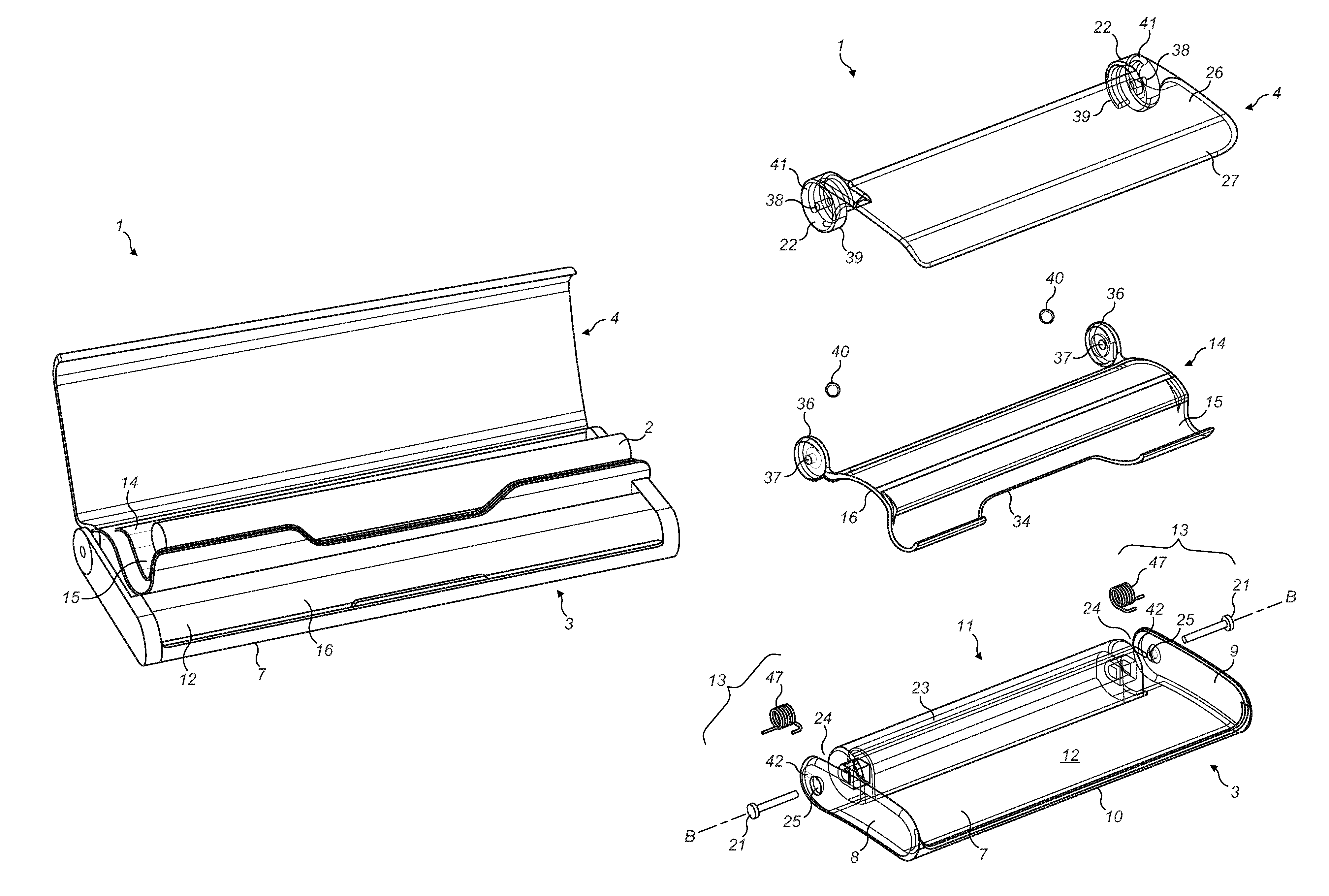
FIG. 3a shows an exploded assembly view of an example of a container for an electronic cigarette.
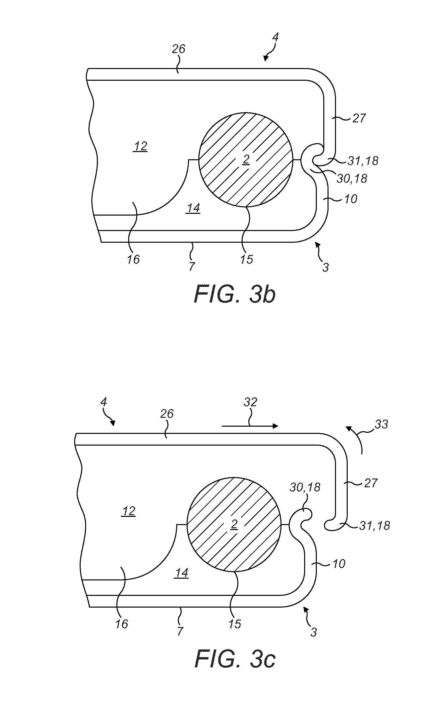
FIGS. 3b and 3c show cross-sectional views of the container of FIG. 3a, with an electronic cigarette received within the container.
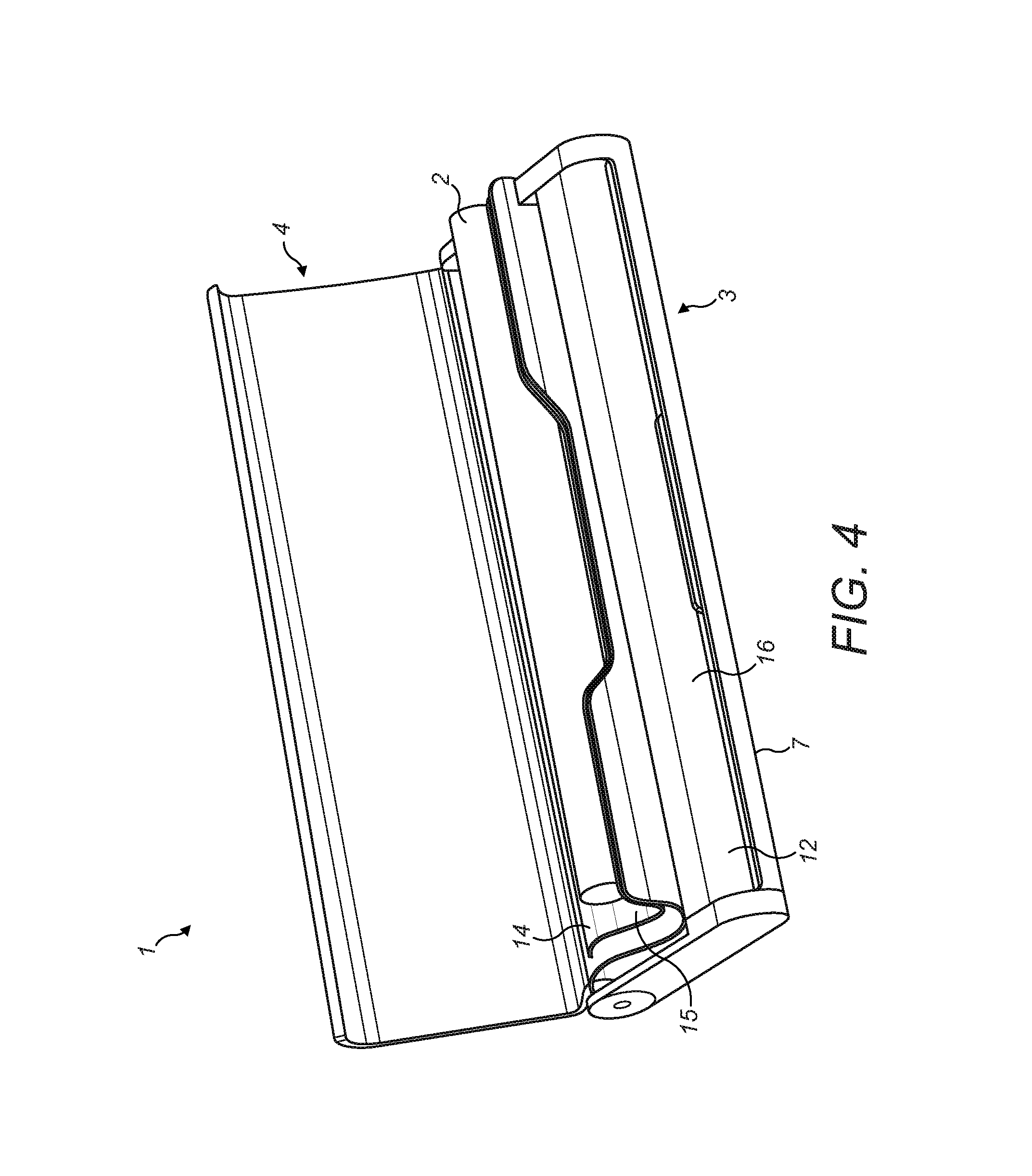
FIG. 4 shows an example of a container for an electronic cigarette, with the lid in an open position.
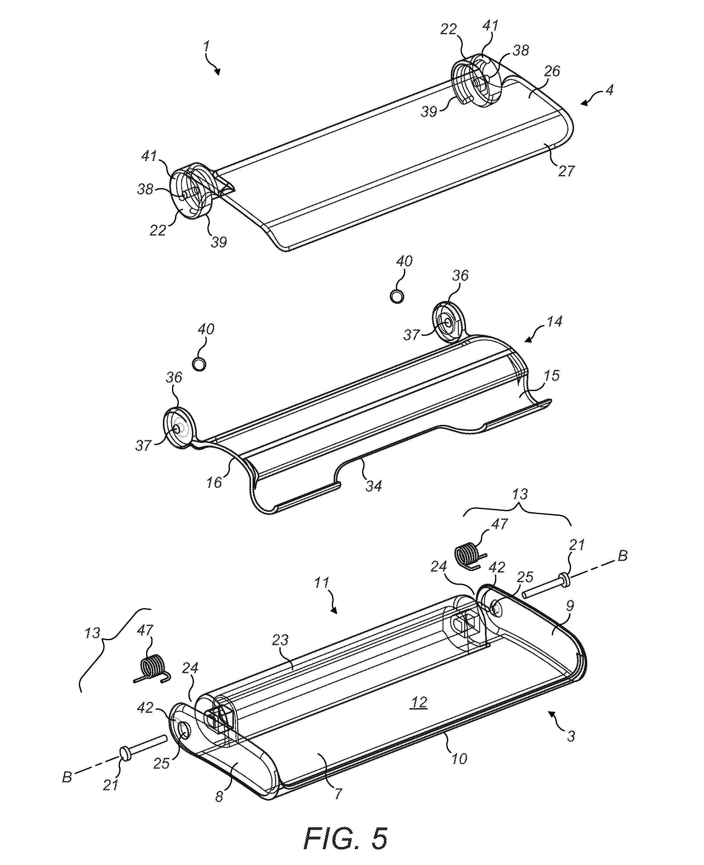
FIG. 5 shows an exploded assembly view of the container of FIG. 4.
FIG. 6a shows an isometric view of the container of FIGS. 4 and 5.
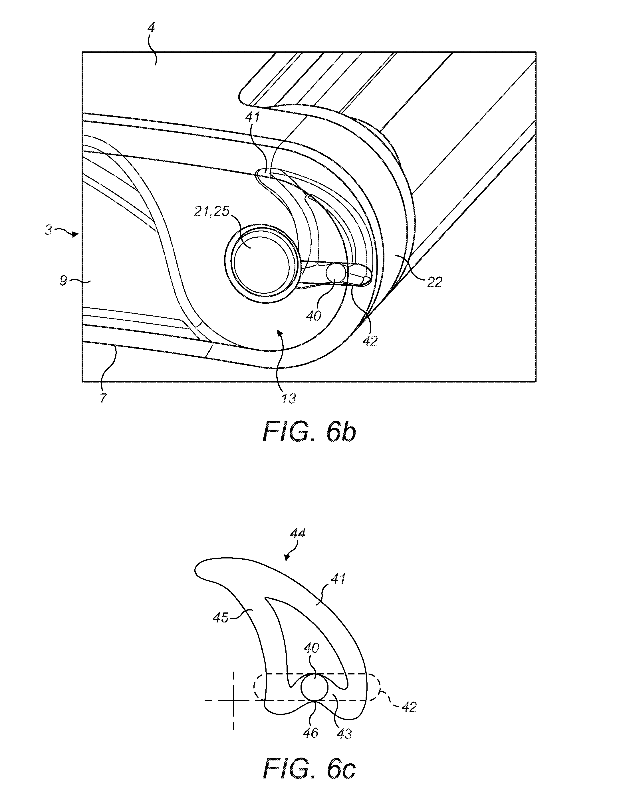
FIG. 6b shows a detailed view of the hinge of the container of FIGS. 4 to 6a, with the lid in a closed position.
FIG. 6c shows the ball and track of the hinge of the container of FIGS. 4 to 6b.
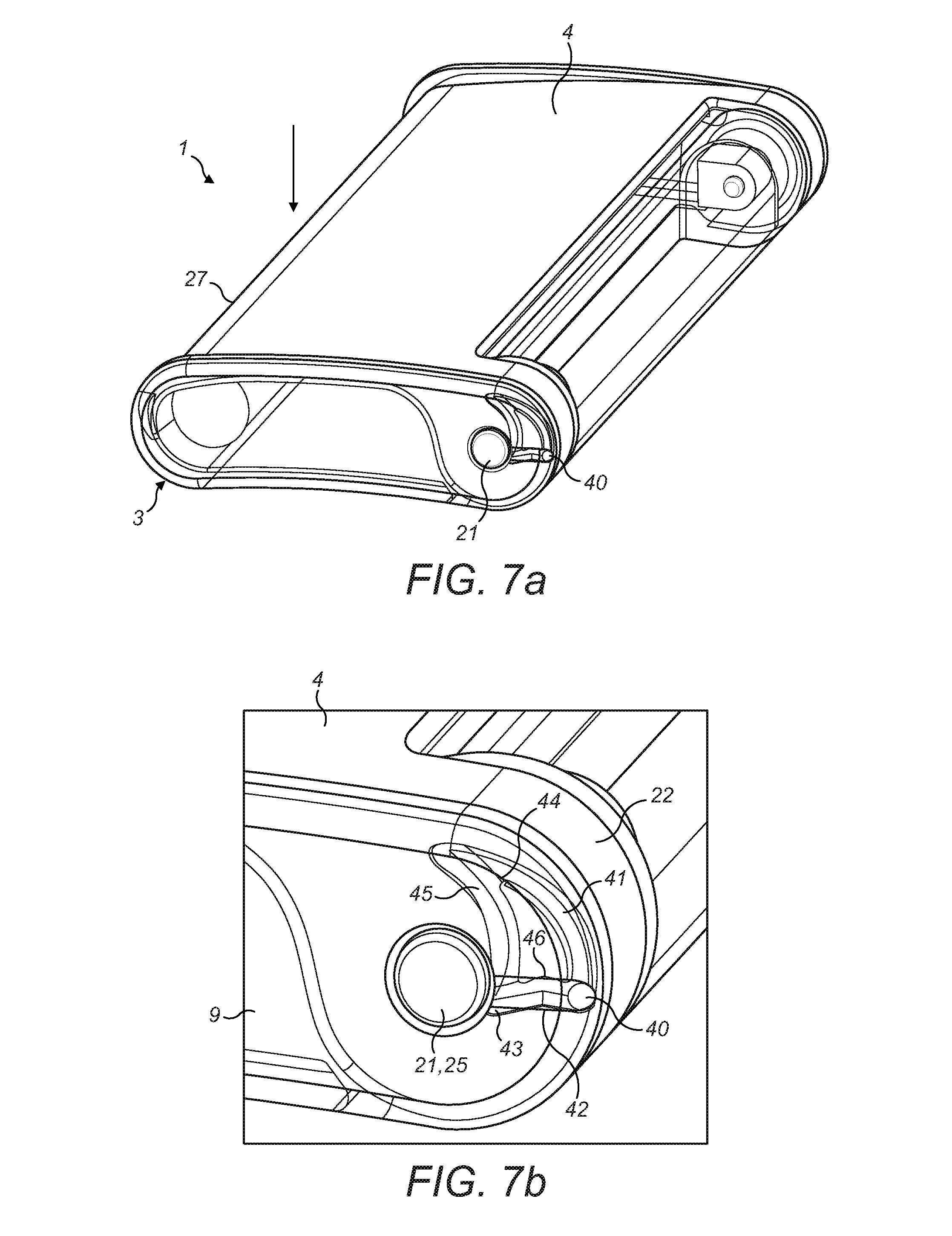
FIG. 7a shows the container of FIGS. 4 to 6c, with the lid in a depressed position during opening.
FIG. 7b shows a close-up view of the hinge of the container of FIGS. 4 to 6c, with the hinge in the position shown in FIG. 7a.
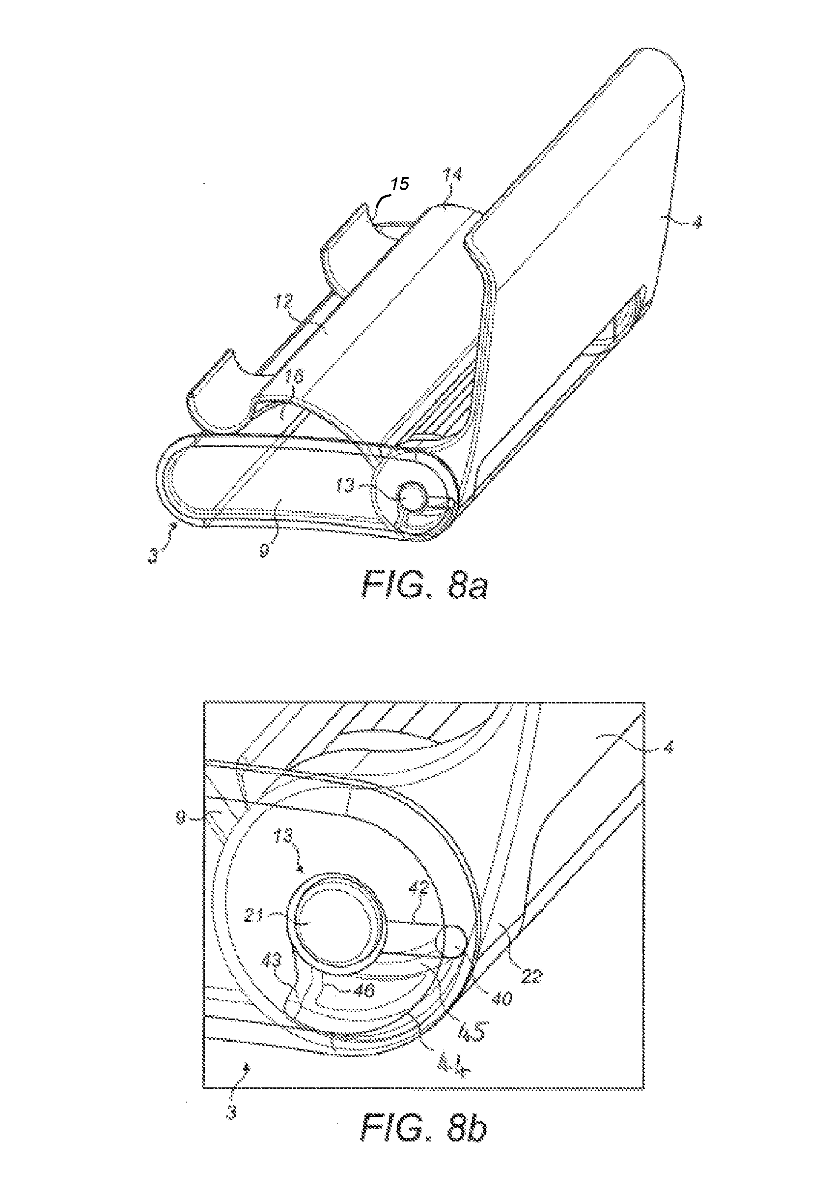
FIG. 8a shows the container of FIGS. 4 to 6c, with the lid in an open position.
FIG. 8b shows a close-up view of the hinge of the container of FIGS. 4 to 6c, with the hinge in the open position shown in FIG. 8a.
DETAILED DESCRIPTION
FIGS. 1a and 1b show a container 1 for an electronic nicotine delivery system having a body 3 and a pivotally attached lid 4. The container 1 is intended to hold an elongate electronic nicotine delivery system, such as an electronic cigarette 2, as shown in FIG. 1b.
Electronic cigarettes have a size and shape, which is similar to conventional cigarettes, and generally have an elongate body having a longitudinal axis A-A. As shown in FIG. 1b, an electronic cigarette 2 will have two ends 5 and an elongate side surface 6. The electronic cigarette may have a constant cylindrical shape so that the elongate side surface 6 is a rounded surface. However, it will be appreciated that other electronic nicotine delivery systems and some electronic cigarettes may have an alternative shape and embodiments are not limited to cylindrical or constant size electronic nicotine delivery systems. For example, an electronic cigarette may have a stepped side, with a change in diameter along its length. Alternatively, an electronic cigarette may have a tapered shape or may have a triangular, square or any other cross-sectional shape, and it will be appreciated that that which is defined in the claims may be used for such products.
As shown in FIGS. 1a and 1b, the container 1 has an elongate body 3 formed of a base wall 7, opposing end walls 8, 9 and opposing side walls 10, 11. The body 3 is elongate such that the base wall 7 is longer in the direction of the side walls 10, 11 than in the direction of the end walls 8, 9. The side walls 10, 11 extend from the longer edges of the base wall 7 in a direction generally perpendicular to the plane of the base wall 7 and the opposing end walls 8, 9 extend from the shorter edges of the base wall 7 in a similar manner. Therefore, the base wall 7, side walls 8, 9 and end walls 10, 11 define a chamber 12 within the body, as shown in FIG. 1b, which is open via an open side of the body 3 which is opposite the base wall 7. As shown in FIGS. 1a and 1b, any of the end walls 8, 9, side walls 10, 11 or edges between the walls of the container 1 may be rounded to provide the container 1 with a rounded or smoothed exterior and therefore make the container 1 easier for a user to hold, carry, use and easier to insert into and retrieve from a pocket.
For example, as shown in FIG. 1a, the container 1 may have a generally kidney bean shaped cross-section with the base wall 7 and an opposing side having a curved profile. This shape may make it easier for a user to hold and use the container and makes the container more comfortable to place into a pocket.
The side walls 10, 11 and end walls 8, 9 extend from the base wall 7 to define a shallow and elongate chamber 12. This gives the body 3 and the container 1 a substantially flat construction within which the chamber 12 is defined.
The open side of the container 1, opposite to the base wall 7, provides access to the chamber 12. The lid 4 is pivotally attached along a side wall 11 of the body 3 to cover the open side of the body 3 and is openable to provide access to the chamber 12. As shown in FIG. 1b, the lid 4 is attached to the body 3 by means of a hinge 13 located along a side wall 11 of the body 3. The hinge 13 may be mounted to the side wall 11 or to the opposing end walls 8, 9 such that the rotational axis B-B of the lid 4 extends in a direction along a side wall 11 of the container 1. As shown in FIG. 1a, when the lid 4 is closed the open side of the body 3 is covered and the chamber 12 is closed. FIG. 1b shows the lid 4 in an open position which allows a user to access the chamber 12 for inserting or retrieving an electronic cigarette 2 within the chamber 12.
As shown in FIG. 1b, the container 1 also has a tray 14 disposed within the chamber 12. The tray 14 extends at least partially across the chamber 12 and may be formed integrally with the body 3, as a part of the base wall 7, or the tray 14 may be formed as an insert which is received within the chamber 12. In this example, the tray 14 extends across the entire chamber 12, covering the base wall 7 of the body 3. The tray 14 has a recessed region 15 which is configured to receive an electronic cigarette 2. In particular, the recessed region 15 is formed as a partly cylindrical recess in the tray 14 that receives an electronic cigarette 2 and supports the electronic cigarette 2 within the chamber 12. As shown in FIG. 1b, for a circular cylindrical electronic cigarette 2, the recessed region 15 may be semi-circular.
As shown in FIG. 1b, the recessed region 15 of the tray 14 is formed in a direction parallel to the elongate side walls 10, 11 of the body 3 such that the longitudinal axis A-A of the electronic cigarette 2 is parallel to the side walls 10, 11 of the body 3 and therefore also parallel to the rotational axis B-B of the hinge 13 between the body 3 and the lid 4. The electronic cigarette 2 is supported by the tray 14 on its elongate side face 6. The electronic cigarette 2 can be inserted into and removed from the tray 14 via the open side of the body 3 when the lid 4 is open.
In this example, the tray 14 received within the chamber 12 also has a compartment 16 which is formed adjacent to the recessed region 15 and is provided to receive an ancillary article (not shown), such as a leaflet or a replacement part for the electronic cigarette 2. As shown in the example of FIG. 1b, the compartment 16 may also comprise a recessed region that occupies the remaining space within the chamber 12.
The example of FIG. 1b shows a tray 14 having a recessed region 15 for an electronic cigarette 2 which is disposed against a front side wall 10 of the body 3, opposite to the side wall 11 to which the hinge 13 is mounted. In this example, the compartment 16 is disposed between the recessed region 15 and the side wall 11 to which the hinge 13 is mounted. However, it will be appreciated that the recessed region 15 and the compartment 16 may be arranged differently within the chamber 12. For example, the recessed region 15 may be disposed against the side wall 11 of the body 3 to which the hinge 13 is mounted, with the compartment 16 occupying the remaining space within the chamber 12. Alternatively, the recessed region 15 may be disposed centrally within the chamber 12, spaced from each side wall 10, 11 of the body 3. In this case, the compartment 16 may be divided into two regions disposed on either side of the recessed region 15.
It will be appreciated that the semi-cylindrical recessed region 15 shown in the example of FIG. 1b is provided for the constant size cylindrical electronic cigarette 2 shown in this example. However, the shape of the recessed region 15 may be altered to suit the electronic cigarette 2 or other type of electronic nicotine delivery system which the tray 14, and the container 1, is configured to receive. For example, the recessed region 15 may comprise a step which changes the size of the recessed region 15 so that the tray 14 is suitable to receive a matching electronic cigarette 2. Alternatively, the recessed region 15 may not be semi-cylindrical and may instead have a triangular or square shape appropriate to receive an electronic nicotine delivery system having a different shape.
When the lid 4 is in a closed position, an inner face 17 of the lid 4 may act to retain the electronic cigarette 2 within the recessed region 15. That is, the electronic cigarette 2 is supported on one side by the tray 14 and when the lid 4 is closed the lid 4 acts to prevent the electronic cigarette 2 from coming out of the recessed region 15 of the tray 14. The inner surface 17 of the lid 4, when closed, may contact the electronic cigarette 2 and thereby hold the electronic cigarette 2 in the recessed region 15. Alternatively, the inner surface 17 of the lid 4, when closed, may be disposed a small distance away from the side surface 6 of the electronic cigarette 2 so that the electronic cigarette 2 is not able to come out of the recessed region 15. Alternatively, the lid 4 may comprise a member (not shown) that extends from the internal surface 7 of the lid 4 to retain the electronic cigarette 2 in the recessed region 15 and such a member may be a solid member or it may be a deformable foam pad. Alternatively, the lid 4 may comprise an additional recess (not shown) which is aligned with the recessed region 15 of the tray 14 when the lid 4 is closed, so that an electronic cigarette 2 received in the container 1 is supported between two opposing recesses when the lid 4 is closed.
As shown in FIG. 1b, the length of the body 3 of the container 1, in particular the length of the chamber 12 and the recessed region 15 within the tray 14, is slightly greater than the length of an electronic cigarette 2. In this way, when an electronic cigarette 2 is received in the chamber 12 there is limited space between each end 5 of the electronic cigarette and the end walls 8, 9 of the body 3 for movement of the electronic cigarette 2 in an axial direction.
As explained above, the example container 1 shown in FIGS. 1a and 1b supports the electronic cigarette 2 within the recessed region 15 and the lid 4 when the lid 4 is closed. When the lid 4 is open, the electronic cigarette 2 is presented to the user and can easily be gripped and removed from the recessed region 15 in the tray 14 by a user. While in the container 1, the electronic cigarette 2 is prevented from moving around significantly and is thereby protected from movement and damage during transportation.
The container 1 may be made from a rigid material, for example a polymer such as polycarbonate, or a metal, such as tin or aluminum. The rigid container 1 will protect the contents from impact, crushing and bending forces and may also provide some protection against dirt and liquids.
The body 3 and/or the lid 4 may be made from an opaque, translucent or transparent polymer material, so that a user may be able to see the contents of the container 1 when it is closed.
As shown in FIG. 1b, the example container 1 may have a locking mechanism 18 that acts to hold the lid 4 in a closed position and which a user can release to allow the lid 4 to be opened. The locking mechanism 18 is formed of two parts; the side wall 10 of the body 3 has a protrusion 19 and the side edge of the lid 4 has a receiving part 20. When the lid 4 is closed, the protrusion 19 and receiving part 20 engage to hold the lid 4 in a closed position. A user is able to lift the receiving part 20 away from the protrusion 19 to release the locking mechanism 18, allowing the lid 4 to be pivotally opened.
The lid 4 is able to rotate between a closed position, in which the open side of the body 3 is covered, and an open position, in which the chamber 12 is exposed. A maximum open position of the lid 4 may be defined by a part of the lid 4 which contacts a part of the body 3 to prevent further rotation in the open direction. Alternatively, the hinge 13 may be configured to have a maximum opening angle.
FIG. 2 shows another example of a container 1 for an electronic cigarette, having a body 3 and a pivotally mounted lid 4 which are similar to those described with reference to FIGS. 1a and 1b. In this example, the hinge 13 between the body 3 and the lid 4 comprises a pin 21 that extends through the end walls 8, 9 of the body 3, a part of the lid 4 and optionally a part of the side wall 11 of the body 3. The side wall 11 of the body 3, along which the hinge 13 extends, may have a cut out that allows a part of the lid 4 to extend around the edge of the container 1 and also allows the lid 4 to rotate into the open position. The pin 21 of the hinge 13 may comprise a single pin 21 that extends along the container 1, or alternatively comprise two pins, one extending through each side wall 8, 9.
The hinge 13 may be provided with a biasing member (not shown), such as a torsion spring, compression spring, extension spring or other resilient member that urges the lid 4 towards the open position. The container 1 may also have a locking mechanism (not shown) which holds the lid 4 in the closed position until a user releases the locking mechanism and allows the lid 4 to rotate into the open position. The locking mechanism will act between the lid 4 and the body 3 and may be positioned on the side wall 10 of the body 3, and corresponding edge of the lid 4, on an opposite side of the container to the hinge 13. Alternatively, the locking mechanism may be located on the end walls 8, 9 of the body 3 or may be integrally formed within the hinge 13 itself. The locking mechanism retains the lid 4 in the closed position, against the force of the biasing member, until a user disengages the locking mechanism at which point the lid 4 is rotated into the open position by the biasing member.
FIG. 3a shows a detailed exploded assembly drawing of an example container 1 which has a construction similar to that described with reference to FIG. 2. In this case, the hinge 13 is formed by a pin 21 extending through each end wall 8, 9 of the body 3, and into two spaced hinge members 22 which extend from the lid 4. In the example shown in FIG. 3a, the pin 21 also extends into the side wall 11 of the body which in this example is formed of a hinge mounting protrusion that extends along the edge of the body 3 between the hinge members 22 of the lid 4. However, it will be appreciated that the pin 21 may not extend into the side wall 11 of the body 3, so long as the pin 21 pivotally connects a part of the body 3 to a part of the lid 4.
As shown in FIG. 3a, the hinge 13 also includes a biasing member 47 to urge the lid 4 into an open position. In this example, the biasing member 47 is a torsion spring, but may alternatively be a compression spring or extension spring arranged to urge the lid 4 to rotate into the open position, or any other resilient member.
In this example, the container 1 has a locking mechanism 18 that is configured to hold the lid 4 in the closed position until the lid 4 is moved in a plane parallel to the base wall 7 of the body 3 to disengage the locking mechanism 18 and allow the lid 4 to rotate under the force of the biasing member 47. That is, to open the container 1, the lid 4 must be moved a small amount in a direction perpendicular to the rotational axis A-A to disengage the holding locking mechanism 18, as explained in more detail below with reference to FIGS. 3b and 3c.
As shown in FIG. 3a, the side wall 11 of the body 3 to which the hinge 13 is mounted comprises a hinge mounting protrusion 23 that extends along the edge of the base wall 7 and has two spaced recesses 24 which are positioned close to the end walls 8, 9 to receive the hinge members 22 of the lid 4. The hinge mounting protrusion 23 forms the side wall 11 of the container and also provides surfaces for the mounting of the hinge. That is, the hinge mounting protrusion 23 comprises end faces at either end of a protrusion that extends along the edge of the base wall 7 to form the side wall 11, such that the end faces are perpendicular to the direction of the side wall 11 and parallel with the end walls 8, 9 of the container and form one side of the hinge mounting recesses 24. An aperture 25 extends through the end walls 8, 9 and optionally partially into each end of the hinge mounting protrusion 23 of the side wall 11, between the two recesses 24, to receive the two pins 21--one from each end of the container.
The lid 4, as shown in FIG. 3a, has a generally planar top wall 26 and a curved front edge 27 so that it matches the shape of the open side of the body 3 and closes the chamber 12 when attached to the body 3. The two spaced hinge members 22 extend from the lid 4 into the spaced recesses 24 in the side wall 11 of the body 3. Each hinge member 22 comprises an aperture 28 that is aligned with the apertures 25 extending through the end walls 8, 9 and the hinge mounting protrusion 23 of the side wall 11 of the body 3 so that the pin 21 can extend through the end walls 8, 9 and hinge members 22 of the lid 4 to pivotally mount the lid 4 to the body 3 about a rotational axis B-B that is parallel to the side wall 11 of the container 1.
The hinge members 22 extending from the lid 4 are formed of a generally cylindrical protrusion which is aligned with the rotational axis B-B of the hinge 13. Each hinge member 22 comprises an aperture 28 through which the pin 21 extends and one side of each hinge member 22 has a recess 29 that is coaxial with the aperture 28 to receive the biasing member 47. That is, a biasing member 47 is disposed in the recess 29 in each hinge member 22 and the pin 21 extends through the hinge member 22 and through the middle of the biasing member 47. In this example, the recess 29 for the biasing member 47 is disposed on a side of the hinge members 22 that faces towards the end walls 8, 9 of the body 3. However, it will be appreciated that the recesses 29 for the biasing members 47 may alternatively be disposed on the inner sides of the hinge members 22. Alternatively, the recesses 29 may be formed in additional components which are positioned between the hinge members 22 and a part of the body 3.
Each hinge member 22 also comprises an anchor (not shown), which may be a hole or a groove or a recess in which a first end of the biasing member 47 is received, or alternatively a protrusion against which an end of the biasing member 47 abuts. The second end of the biasing member is received within a second anchor provided on the side wall 11 of the body 3.
In this way, the first end of each biasing member 47 is anchored to the lid 4 and the second end of each biasing member 47 is anchored to the body 3, while the pins 21 provide a pivotal relationship, so that the lid 4 is pivotally mounted to the body 3 and the biasing members 47 urge the lid 4 to rotate about the pins 21 towards an open position.
As shown in FIG. 3a, the apertures 28 in the hinge members 22 of the lid 4 are formed as elongate slots. The apertures 28 are elongated in a direction parallel to the plane of the top wall 26 of the lid 4, which is parallel to the base wall 7 of the body 3 when the lid 4 is closed. Therefore, the lid 4 is pivotally mounted through rotation about the pins 21, and also slidably mounted through movement of the lid 4 along the slotted apertures 28. The slotted apertures 28 are configured such that when the lid 4 is positioned with the pins 21 at a first end of the slotted apertures 28, the locking mechanism 18 is engaged and the lid 4 is locked in a closed position, with the front edge of the lid 4 aligned with the front edge of the body 3 to close the chamber 12. When the lid 4 is slidably moved in a lateral direction, so that the pins 21 are positioned at the second end of the slotted apertures 28, the front edge of the lid 4 has moved away from the front edge of the body 3 in a direction away from the hinge 13, which causes the locking mechanism to disengage and allows the lid 4 to rotate into the open position under the force of the biasing member 47.
FIG. 3b shows a cross-sectional view of the container 1 of FIG. 3a, taken across one of the end walls 8, 9 of the container 1. As shown in FIG. 3b, when the lid 4 is in a closed position, the locking mechanism 18 is engaged and a first locking part 30 on the side of the body 3 which is opposite to the hinge (see FIG. 3a), engages with a second locking part 31 on the front edge 27 of the lid 4 to lock the lid 4 and prevent rotation relative to the body 3. In this example, the first locking part 30 comprises a protrusion and the second locking part 31 comprises a recess. The protrusion 30 and the recess 31 engage each other to providing a holding force that locks the lid 4 in a closed position. However, it will be appreciated that the first and second locking parts 30, 31 may be formed in any shape that is able to engage together and provide the holding force.
As shown in FIG. 3c, when the lid 4 is slidably moved in a lateral direction along the slotted apertures (28, see FIG. 3a), in the direction of the arrow 32, the first and second locking parts 30, 31 are moved away from each other and the lid 4 is released allowing it to rotate in the direction of arrow 33, into the open position.
In this example, the first and second locking parts 30, 31 of the locking mechanism 18 are formed in the front edge of the body 3 and the lid 4 respectively. However, it will be appreciated that the locking mechanism 18 comprising the first and second locking parts 30, 31 may be provided in any position along the front edge 27 of the body 3 and the lid 4. For example, the first and second locking parts 30, 31 may extend along the entire front edge of the body 3 and the lid 4. For example, the first and second locking parts 30, 31 may be formed in a central part of the front edge 27 of the lid 4, or in any other position between the lid 4 and the body 3. In another example, the second locking part 31 may be formed in each end wall 8, 9 of the body 3 and in each end of the front edge 27 of the lid 4. In any case, the first and second locking parts 30, 31 will engage when the lid 4 is in a closed position.
As shown in FIG. 3a and as previously explained, the side wall 11 of the body 3 to which the hinge 13 is mounted is formed of a generally cylindrical hinge mounting protrusion 23 that extends along the side wall 11 of the body 3. The hinge members 22 of the lid 4 are also formed as generally cylindrical protrusions. The cylindrical side wall 23 and hinge members 22 are configured to match each other such that when the lid 4 is mounted to the body 3 the exterior of the container 1 is smooth and continuous. Furthermore, when the lid 4 is rotated into the open position, the exterior of the container 1 remains continuous because the cylindrical shape of the side wall 11 of the body 3 and the hinge members 22 of the lid are matching and also aligned with the rotational axis B-B of the hinge 13. However, it will be appreciated that the hinge members 22 of the lid 4 and the side wall 11 of the body 3 may have other shapes.
The tray 14 which supports the electronic cigarette 2 and ancillary article is also shown in FIGS. 3a, 3b and 3c. In this example, the tray 14 is formed as an insert which is received within the chamber 12 of the body 3. As shown in FIGS. 3b and 3c, in this example, the insert 14 comprises a first recessed region 15 to receive and support an electronic cigarette 2 and a compartment 16 to receive an ancillary article (not shown). As shown in FIG. 3a, the tray 14 may also comprise two further recesses 34, 35, extending partly along the recessed region 15 and compartment 16 to allow a user to more easily grasp an electronic cigarette or ancillary article received in the tray 14. These recesses 34, 35 may be positioned centrally, as shown in FIG. 3a. Alternatively, they may be positioned anywhere in the tray 14 along the recessed region 15 and/or the compartment 16.
FIG. 4 shows another example of a container 1 for an electronic cigarette 2, having a body 3 and a pivotally mounted lid 4 similar to the container 1 described with reference to FIGS. 1a and 1b. In this example, the tray 14 within the chamber 12 is an insert which is pivotally mounted to the body 3 and coupled to the lid 4 so that as the lid 4 is rotated into an open position the tray 14 is partially rotated into a lifted position, as shown. The tray 14 rotates by a smaller amount than the lid 4, so that tray 14 is lifted to a position intermediate the base wall 7 of the body 3 and the lid 4 when the lid 4 is in an open position. Therefore, the electronic cigarette 2 received on the tray 14 is presented to the user and the space between the tray 14 and the base wall 7, within the chamber 12, becomes accessible to the user. In this example, the tray 14 is provided with a first recessed region 15 on the top of the tray 14 for the electronic cigarette 2 and the compartment 16 is provided beneath the tray 14, and becomes accessible when the tray 14 is partially rotated on opening of the lid 4.
FIG. 5 shows a detailed exploded assembly view of the container 1 of FIG. 4. In this example, as explained above, the tray 14 is pivotally mounted to the body 3 and coupled to the lid 4 so that as the lid 4 is opened the tray 14 is partially rotated within the chamber 12.
As shown in FIG. 5, the tray 14 of this example is provided with a first recessed region 15 to receive an electronic cigarette and a compartment 16, on a side of the tray 14 opposite to the first recessed region 15, to receive an ancillary article between the tray 14 and the base wall 7 of the body 3, as described with reference to FIG. 4. Therefore, the compartment 16 is only accessible when the tray 14 has been lifted into the position shown in FIG. 4. In this example, the tray 14 is provided with a recess 34, such that an electronic cigarette can easily be removed from the recessed region 15 in the tray 14.
FIG. 5 also shows the components of the hinge 13 of this example container 1. The hinge 13 of this example container has a biasing member 47 that urges the lid 4 to rotate into the open position shown in FIG. 4. The biasing member 47 may be a torsion spring, as shown in FIG. 5, or may alternatively be a compression spring or extension spring arranged to urge the lid into an open position or may be any other resilient member. The hinge 13 of this example container 1 has a locking mechanism that locks the lid 4 in a closed position until a user applies a downward force on the lid 4, which releases the locking mechanism and allows the lid 4 to rotate to the open position under the force of the biasing member 47. The lid 4 is closeable by rotating the lid 4 back into the closed position and applying a further downward force to engage the locking mechanism.
The side wall 11 of the body 3 to which the hinge 13 is mounted comprises a hinge mounting protrusion 23 that extends along the side wall 11 and has two spaced recesses 24 to receive the hinge members 22 of the lid 4. The hinge mounting protrusion 23 forms the side wall 11 of the container and also provides surfaces for the mounting of the hinge 13. That is, the hinge mounting protrusion 23 comprises end faces at either end of a protrusion that extends along the edge of the base wall 7 to form the side wall 11, such that the end faces are perpendicular to the direction of the side wall 11 and parallel with the end walls 8, 9 of the container and form one side of the hinge mounting recesses 24. The hinge members 22 of the lid 4 extend from the lid 4 into the spaced recesses 24 formed in the side wall 11 of the body 3 in a similar manner to that described with reference to FIG. 3a. The tray 14 also comprises two hinge members 36 that extend into the spaced recesses 24 in the side wall 11 of the body 3 so that the hinge members 22 of the lid 4 and the hinge members 36 of the tray 14 are adjacent to each other in the spaced recesses 24. Each of the hinge members 22, 36 has an aperture 38, 37 that is aligned with apertures 25 in the end walls 8, 9 of the body 3 so that a pin 21 can extend through each end wall 8, 9 and through the hinge members 22, 36 to pivotally mount the lid 4 and tray 14 to the body 3. The apertures 25 formed in the end walls 8, 9 of the body may extend into the side wall protrusion 23 of the body 3 to receive the ends of the pins 21. In this example, the hinge members 36 of the tray 14 are disposed on an inner side, between the hinge members 22 of the lid 4. However, it will be appreciated that the arrangement of the hinge members 22, 36 within the spaced recesses 24 in the side wall 11 of the body 3 may be different.
The biasing means 47 are received in a recess formed in the hinge mounting protrusion 23 of the side wall 11 of the body and are anchored to both the side wall 11 of the body and the hinge members 22 of the lid 4 in a similar manner to the example container described with reference to FIG. 3a.
The two hinge members 22 of the lid 4 each comprise a circular protrusion that extends from the lid 4 and are coaxially aligned with the rotational axis B-B of the lid 4. Each hinge member 22 of the lid 4 has a protrusion in the form of a circumferential shoulder 39 that extends from the hinge member 22, partially around the circumference of the hinge member 22, towards the hinge member 36 of the tray 14. This shoulder 39 is disposed to contact the tray 14 as the lid 4 is pivoted open and to push the tray 14 such that it pivots into the open position shown in FIG. 4. In particular, as the lid 4 is rotated from the closed position towards the open position it will rotate independently of the tray 14 for a predetermined angle until the shoulders 39 of the hinge members 22 of the lid 4 engage with the tray 14, after which further rotation of the lid 4 will cause the tray 14 to rotate with the lid 4. In this way, the tray 14 is rotatably coupled to the lid 4 so that when the lid 4 is opened the tray 14 is rotated to the intermediate position shown in FIG. 4. In this example, each hinge member 22 of the lid 4 has a shoulder 39. However, it will be appreciated that only one of the hinge members 22 may be provided with a shoulder 39 to contact and rotate the tray 14.
It will be appreciated that the rotating tray described with reference to FIGS. 4 and 5 may be provided to any of the containers 1 described with reference to any of the other Figures.
The hinge 13 of the example container shown in FIG. 5 also has a locking mechanism which can be engaged to lock the lid 4 in the closed position and can be disengaged to allow the lid 4 to rotate into the open position. The locking mechanism is disengaged by depressing and releasing the lid 4 to allow the lid to rotate to the open position. The locking mechanism can then be re-engaged by rotating the lid to the closed position and depressing the lid 4 further before releasing the lid 4. This is explained in more detail with reference to FIGS. 6a to 8b below.
As shown in FIG. 5, the hinge 13 is formed of two parts, one on each side of the container 1, and each hinge comprises a locking mechanism. However, it will be appreciated that only one locking mechanism may be required in which case only one part of the hinge may be provided with a locking mechanism. Each locking mechanism has a cam element 40 which is disposed between the hinge member 22 of the lid 4 and the end wall 8, 9 of the body 3, in a track 41 formed in the hinge member 22 and a groove 42 formed in the end wall 8, 9, as explained in detail below with reference to FIGS. 6a to 8b.
FIG. 6a shows the container 1 of FIGS. 4 and 5 with the lid 4 in a closed position, covering the open side of the body 3 and enclosing the chamber. As shown, the hinge members 22 of the lid 4 are received in the spaced recesses 24 of the side wall 11 of the body 3, between the end walls 8, 9 and the hinge mounting protrusion 23 of the side wall 11, and a hinge pin 21 extends through each end wall 8, 9 and the hinge members 22 and into the hinge mounting protrusion 23 to pivotally mount the lid 4 to the body 3. In the closed position, the lid 4 is in a stable position with the lid 4 being flush with the end walls 8, 9 and side walls 10, 11 of the body 3.
FIG. 6b shows an enlarged view of the hinge 13 of the container 1 of FIG. 6a, with the components of the container 1 shown as translucent so that internal components are visible. As shown, the end wall 9 of the body 3 comprises a groove 42 which extends from the hinge aperture 25 away from the pin 21, towards the side wall 11 of the body 3 in a direction parallel to the base wall 7 of the body 3. The hinge member 22 of the lid 4, which is disposed adjacent to the end wall 9, comprises a track 41 which includes three portions, as shown in FIG. 6c: a first portion 43 having a bend 46; a second portion 44 which extends from an end of the first portion 43, circumferentially around the hinge member 22 co-axially with the rotational axis B-B (see FIG. 5) of the hinge 13; and a third portion 45 which extends between the second portion 44 and the first portion 43 in a curved manner with a circumference which is the same as the second portion 44 of the track 41, but disposed at a different angle.
In this way, the track 41 is a closed loop and defines a fixed loop path for the cam element 40 which is retained in the track 41 and the groove 42, between the end wall 9 of the body 3 and the hinge member 22 of the lid 4, during rotation of the lid 4. The track 41 defines an endless path around which the cam element 40 is moved. In this example, the cam element is a ball bearing 40 that is moved around the track 41 during rotation of the lid 4. However, it will be appreciated that the ball bearing may be replaced with another suitable element that is capable of being moved around the track to lock and unlock the lid 4 in the manner described below.
As shown in FIGS. 6b and 6c, when the lid 4 is in a closed position the ball bearing 40 is disposed in the bend 46 of the first portion 43 of the track 41 in the hinge member 22 and in an intermediate part of the groove 42 in the end wall 9. The first portion 43 of the track 41 and the groove 42 are arranged in the hinge 13 such that when the lid 4 is in the closed position, with the biasing member (47, See FIG. 6) urging the lid towards the open position, the groove 42, track 41 and ball bearing 40 combine to cause the ball bearing 40 to be urged into the bend 46 of the first portion 43 of the track 41. Therefore, the ball bearing 40 is urged into a stable position, where the biasing member holds the ball bearing 40 in the bend 46 and prevents movement of the lid 4. A force is required to move the ball bearing 40 along the first portion 43 of the track 41 and out of the bend 46, to allow the lid 4 to open.
FIG. 7a shows the container 1 described with reference to FIGS. 5 to 6c with the lid 4 in a depressed position, which causes the locking mechanism to disengage and allows the lid 4 to open. This is the position to which the lid 4 must be moved by a user to move the ball bearing 40 from the stable position in the bend 46 of the track 41, as shown in FIG. 6b, to an unstable position which allows the ball bearing 40 to move around the second portion 44 of the track 41 and thereby allow the lid 4 to rotate to the open position under influence of the biasing member. In particular, a user must depress the lid 4 by pushing down on the lid 4 so that the front edge 27 of the lid 4 rotates towards the base wall 7 of the body 3, as shown in FIG. 7a.
FIG. 7b shows an enlarged view of an end of the container 1, showing the hinge components in more detail, when the lid 4 is in the position described with reference to FIG. 7a. As shown in FIG. 7b, by pushing down on the lid 4 the angle between the track 41 in the hinge member 22 and the groove 42 in the end wall 9 has caused the ball bearing 40 to move along the first portion 43 of the track 41 away from the bend 46 and the pin 21 and into the second portion 44 of the track 41. Therefore, the ball bearing 40 is now positioned at the end of the groove 42 in the end wall 9, remote from the pin 21, and in the join between the first portion 43 and the second portion 44 of the track 41. The ball bearing 40 is now in an unstable position and when the lid 4 is released by the user the biasing member 47 (see FIG. 5) rotates the lid 4 into the open position and the ball bearing 40 is moved along the second portion 44 of the track 41. Therefore, the lid 4 is able to rotate until the ball bearing 40 reaches the end of the second portion 44, where it joins the third portion 45 of the track 41, as shown in FIGS. 8a and 8b. In this position the lid 4 is prevented from further rotation and the lid 4 is held in the open position.
As shown in FIG. 8a, the lid 4 rotates to an open position in which the chamber 12 is accessible. In this example, the tray 14 is pivotally coupled to the lid 4, as described with reference to FIG. 5, and the tray 14 is shown in the raised position with the recessed region 15 on top of the tray 14 and the compartment 16 below the tray 14.
FIG. 8b shows an enlarged view of the hinge 13 of the container of FIG. 8a, in the open position, and shows the hinge components. As shown, the ball bearing 40 is now disposed at the join between the second portion 44 and third portion 45 of the track 41 in the hinge member 22 and the end of the groove 42 remote from the hinge pin 21. Therefore, the biasing member 47 (see FIG. 5) is pushing the ball bearing 40 into the join between the second and third portions 44, 45 of the track 41 which is a stable position and the lid 4 is at its maximum opening angle. The length of the second portion 44 of the track 41, the angle around the hinge member 22 which the second portion 44 of the track 41 extends, will define the open position of the lid 4.
When a user rotates the lid 4 back to the closed position the ball bearing 40 will move from the position shown in FIG. 8b into and along the third portion 45 of the track 41 in the hinge member 22 which also pushes the ball bearing 40 along the groove 42 in the end wall 9 towards the hinge pin 21. When the lid 4 is rotated past the closed position and is released the ball bearing 40 will re-enter the first portion 43 of the track 41 and the biasing member will push the ball bearing 40 back into the bend 46, which is the stable closed position shown in FIG. 6b.
Therefore, as described above, during opening and closing of the lid 4 the ball bearing 40 moves around a closed track 41 formed in the hinge member 22 of the lid 4 and a linear groove 42 formed in the end wall 9 of the body 3. The ball bearing 40, which is moved by a combination of the groove 42 in the end wall 9, the track 41 in the hinge member 22 and the biasing member 47, has two stable positions: a stable closed position is defined when the ball bearing 40 is disposed in the bend 46 of the first portion 43 of the track 41; and, a stable open position is defined when the ball bearing 40 is disposed at the join between the second and third portions 44, 45 of the track 41.
It will be appreciated that the track 41 and the groove 42 may be arranged differently to that described with reference to FIGS. 6a to 8b. For example, the groove 42 may be formed in the hinge member 22 of the lid and the track 41 may be formed in the end wall 9 of the body 3. Alternatively, the track 41 and groove 42 may be disposed on the other side of the hinge member 22, with one of the groove 42 or track 41 being formed in a part of the side wall 11 of the body 3. It will be also be appreciated that the groove 42 need not be disposed parallel to the base wall 7 of the container, as shown in FIGS. 6a to 8b, and may be disposed at any angle to the pin 21, with the position of the track 41 being adjusted accordingly.
It will be appreciated that the push-to-open/close locking mechanism described with reference to FIGS. 6a to 8c may be used on other example containers that do not have the partially rotating tray feature. The locking mechanism described with reference to FIGS. 6a to 8b may be used on any of the containers described with reference to the Figures.
The containers 1 described with reference to the Figures all hold an electronic nicotine delivery system 2 in a closed and secure manner, within a rigid and robust container, so that the item is protected whenever the electronic nicotine delivery system is not being used, for example when being carried, used, held, stored and during storage and sales display. The containers 1 described are easy to open and provide unimpeded access to any electronic nicotine delivery system 2 disposed within such a container 1, as well as providing space for ancillary articles, such as product information leaflets or spare parts. The smooth exterior of the containers 1 allows a user to easily put the container 1 in their pocket and extract it without any part of the container getting caught or stuck.
The containers described with reference to the drawings are made from a strong and durable material and provide protection against impacts, dropping, shaking and against damage caused by dirt, or grit and even at least partial protection against water and other liquids. Moreover, the closing action and the locking mechanisms of the containers are reliable and simple to use so a user is able to easily open and close the containers during use.
In order to address various issues and advance the art, the entirety of this disclosure shows by way of illustration various embodiments in which the claimed invention(s) may be practiced and provide for superior container for an electronic nicotine delivery system. The advantages and features of the disclosure are of a representative sample of embodiments only, and are not exhaustive and/or exclusive. They are presented only to assist in understanding and teach the claimed features. It is to be understood that advantages, embodiments, examples, functions, features, structures, and/or other aspects of the disclosure are not to be considered limitations on the disclosure as defined by the claims or limitations on equivalents to the claims, and that other embodiments may be utilized and modifications may be made without departing from the scope and/or spirit of the disclosure. Various embodiments may suitably comprise, consist of, or consist essentially of, various combinations of the disclosed elements, components, features, parts, steps, means, etc. In addition, the disclosure includes other inventions not presently claimed, but which may be claimed in future.
* * * * *
D00000
D00001
D00002
D00003
D00004
D00005
D00006
D00007
D00008
D00009
D00010
XML
uspto.report is an independent third-party trademark research tool that is not affiliated, endorsed, or sponsored by the United States Patent and Trademark Office (USPTO) or any other governmental organization. The information provided by uspto.report is based on publicly available data at the time of writing and is intended for informational purposes only.
While we strive to provide accurate and up-to-date information, we do not guarantee the accuracy, completeness, reliability, or suitability of the information displayed on this site. The use of this site is at your own risk. Any reliance you place on such information is therefore strictly at your own risk.
All official trademark data, including owner information, should be verified by visiting the official USPTO website at www.uspto.gov. This site is not intended to replace professional legal advice and should not be used as a substitute for consulting with a legal professional who is knowledgeable about trademark law.