Electrical contact spring with extensions
Glick , et al. Ja
U.S. patent number 10,193,247 [Application Number 15/812,383] was granted by the patent office on 2019-01-29 for electrical contact spring with extensions. This patent grant is currently assigned to Lear Corporation. The grantee listed for this patent is Lear Corporation. Invention is credited to Michael Glick, David Menzies, Deborah Probert, Tulasi Sadras-Ravindra.


| United States Patent | 10,193,247 |
| Glick , et al. | January 29, 2019 |
Electrical contact spring with extensions
Abstract
An electrical terminal assembly includes a contact member. The contact member has a contact base. A plurality of contact arms extend from the contact base in an arm direction. The electrical terminal assembly includes a spring member supported on the contact member. The spring member includes a spring base. A plurality of spring arms extend from the spring base in the arm direction. The spring arms engage the plurality of contact arms. The spring member includes a shroud. The shroud extends in the arm direction around and beyond the contact arms. A shroud extension extends from the shroud opposite the arm direction. The shroud extension engages the contact base.
| Inventors: | Glick; Michael (Farmington Hills, MI), Sadras-Ravindra; Tulasi (Canton, MI), Probert; Deborah (Farmington Hills, MI), Menzies; David (Linden, MI) | ||||||||||
|---|---|---|---|---|---|---|---|---|---|---|---|
| Applicant: |
|
||||||||||
| Assignee: | Lear Corporation (Southfield,
MI) |
||||||||||
| Family ID: | 65032137 | ||||||||||
| Appl. No.: | 15/812,383 | ||||||||||
| Filed: | November 14, 2017 |
| Current U.S. Class: | 1/1 |
| Current CPC Class: | H01R 11/22 (20130101); H01R 4/48 (20130101); H01R 13/18 (20130101) |
| Current International Class: | H01R 11/22 (20060101); H01R 4/48 (20060101) |
References Cited [Referenced By]
U.S. Patent Documents
| 4453799 | June 1984 | Inoue |
| 4540235 | September 1985 | Lolic |
| 4932877 | June 1990 | Zinn |
| 4934965 | June 1990 | Buddrus |
| 5334058 | August 1994 | Hotea |
| 5437566 | August 1995 | Zinn |
| 5695368 | December 1997 | Joly |
| 5833500 | November 1998 | Mahon |
| 5863225 | January 1999 | Liebich |
| 5868590 | February 1999 | Dobbelaere |
| 5938485 | August 1999 | Hotea |
| 5951336 | September 1999 | Seko |
| 5954548 | September 1999 | Stabroth |
| 6203385 | March 2001 | Sato |
| 6283803 | September 2001 | Sato |
| 6872103 | March 2005 | Flieger |
| 7252559 | August 2007 | Morello |
| 7595715 | September 2009 | Pavlovic |
| 7876193 | January 2011 | Pavlovic et al. |
| 7892050 | February 2011 | Pavlovic |
| 7909663 | March 2011 | Bouffet |
| 7988505 | August 2011 | Hotea |
| 8182299 | May 2012 | Schrader |
| 8366497 | February 2013 | Glick |
| 8449338 | May 2013 | Gong |
| 8475220 | July 2013 | Glick |
| 8827754 | September 2014 | Lee |
| 8992270 | March 2015 | Glick |
| 8998655 | April 2015 | Glick |
| 9011186 | April 2015 | Wirth |
| 9142902 | September 2015 | Glick |
| 9190756 | November 2015 | Glick |
| 9293852 | March 2016 | Glick |
| 9300069 | March 2016 | Morello et al. |
| 9379470 | June 2016 | Glick |
| 9437974 | September 2016 | Glick |
| 9444205 | September 2016 | Rangi |
| 9450331 | September 2016 | Luo |
| 9515403 | December 2016 | Hirakawa |
| 9525254 | December 2016 | Chen |
| 9548553 | January 2017 | Glick |
| 9711926 | July 2017 | Belanger, Jr. |
| 9799980 | October 2017 | Jakoplic |
| 9847591 | December 2017 | Glick |
| 9905953 | February 2018 | Pavlovic |
| 2001/0019924 | September 2001 | Heimueller |
| 2009/0053941 | February 2009 | Stuklek |
| 2010/0216354 | August 2010 | Copper |
| 2010/0216355 | August 2010 | Copper |
| 2010/0323563 | December 2010 | Pavlovic |
| 2011/0076901 | March 2011 | Glick |
| 2012/0129407 | May 2012 | Glick |
| 2014/0030934 | January 2014 | Wirth |
| 2014/0087601 | March 2014 | Glick |
| 2014/0087602 | March 2014 | Glick |
| 2014/0227915 | August 2014 | Glick |
| 2014/0235113 | August 2014 | Glick |
| 2014/0273659 | September 2014 | Glick |
| 2015/0038000 | February 2015 | Glick |
| 2015/0038024 | February 2015 | Glick |
| 2015/0079859 | March 2015 | Glick |
| 2015/0229056 | August 2015 | Morello |
| 2015/0255912 | September 2015 | Natter |
| 2015/0255924 | September 2015 | Glick |
| 2015/0303593 | October 2015 | Ono |
| 2015/0303604 | October 2015 | Rivera |
| 2016/0226177 | August 2016 | Chen |
| 2016/0233635 | August 2016 | Chen |
| 2016/0344129 | November 2016 | Jakoplic |
Attorney, Agent or Firm: MacMillan, Sobanski & Todd, LLC
Claims
What is claimed is:
1. An electrical terminal assembly comprising: a contact member including a contact base that defines an interior space and a plurality of contact arms that extends from the contact base in an arm direction; and a spring member supported on the contact member and including a spring base that extends through the interior space, a plurality of spring arms that extends from the spring base in the arm direction and engages the plurality of contact arms, a shroud that extends in the arm direction around and beyond the contact arms, and a shroud extension that extends from the shroud opposite the arm direction and engages the contact base.
2. The electrical terminal assembly of claim 1, wherein the shroud includes a shroud connector that extends from the spring base to the shroud, the shroud extension extending opposite the arm direction past the shroud connector.
3. The electrical terminal assembly of claim 2, wherein the shroud extension extends opposite the arm direction past the spring base.
4. The electrical terminal assembly of claim 1, wherein the shroud extension extends opposite the arm direction past the spring base.
5. The electrical terminal assembly of claim 1, wherein the shroud extends from the spring base in the arm direction, and the shroud extension extends from the spring base opposite the arm direction.
6. The electrical terminal assembly of claim 5, wherein the shroud extension engages a first outer surface, a second outer surface, and a third outer surface of the contact base.
7. The electrical terminal assembly of claim 6, wherein the shroud includes a second shroud extension that engages the first outer surface, the third outer surface, and a fourth outer surface of the contact base.
8. The electrical terminal assembly of claim 1, wherein the contact base defines a slot, and wherein the shroud extension is located in the slot.
9. The electrical terminal assembly of claim 8, wherein the spring arms are located on opposed sides of a terminal plane, and the shroud extension is located on the terminal plane.
10. The electrical terminal assembly of claim 9, wherein the shroud includes a second shroud extension that is located in a second slot on the contact base.
11. The electrical terminal assembly of claim 10, wherein the second shroud extension is located on the terminal plane.
12. An electrical terminal assembly comprising: a contact member including a contact base that defines an interior space and a plurality of contact arms that extends from the contact base in an arm direction, the contact base defining a slot; and a spring member supported on the contact member and including a spring base that extends through the interior space, a plurality of spring arms that extends from the spring base in the arm direction and engages the plurality of contact arms, a shroud that extends in the arm direction around and beyond the contact arms, and a shroud extension that extends from the shroud opposite the arm direction and is located in the slot on the contact base.
13. The electrical terminal assembly of claim 12, wherein the plurality of spring arms are located on opposed sides of a terminal plane, and wherein the shroud extension is located on the terminal plane.
14. The electrical terminal assembly of claim 13, wherein the shroud includes a second shroud extension that is located in a second slot on the contact base.
15. The electrical terminal assembly of claim 14, wherein the second shroud extension is located on the terminal plane.
16. The electrical terminal assembly of claim 15, wherein the shroud extension and the second shroud extension each extend opposite the arm direction past the spring base.
17. An electrical terminal assembly comprising: a contact member including a contact base that defines an interior space and first and second opposed contact arms that extend from the contact base in an arm direction; and a spring member including a spring base that extends through the interior space, first and second opposed spring arms that extend from the spring base in the arm direction and respectively engage the first and second opposed contact arms, a shroud that extends in the arm direction around and beyond the contact arms, and a shroud extension that extends from the shroud opposite the arm direction and engages the contact base.
18. The electrical terminal assembly of claim 17, wherein the shroud extends from the spring base in the arm direction, and the shroud extension extends from the spring base opposite the arm direction.
19. The electrical terminal assembly of claim 17, wherein the contact member includes first and second opposed pairs of contact arms that extend from the contact base in an arm direction, and wherein the spring base extends through the interior space between the first and second opposed pairs of contact arms.
20. The electrical terminal assembly of claim 17, wherein the shroud includes a shroud connector that extends from the spring base to the shroud, the shroud extension extending opposite the arm direction past the shroud connector.
Description
BACKGROUND OF THE INVENTION
This invention relates in general to a spring for use with a female electrical terminal. More specifically, this invention relates to a spring with a stabilizing feature for use with a female electrical terminal.
Electrical terminals commonly include a female terminal and a corresponding male terminal that may be mated to establish an electrical connection. Male electrical terminals are manufactured in various shapes, including pins and blades, and female electrical terminals are manufactured in complementary shapes that can engage the appropriate male terminal. Female terminals often include a contact portion with multiple contact arms that press onto sides of the male terminal. It is known to provide a female terminal with a spring member to increase the compression force between the male terminal and the female terminal. An example of one such spring is shown in U.S. Pat. No. 7,892,050. The spring member is typically made of a material that, compared to the material of the contact portion, has inferior electrical conductivity but is less susceptible to relaxation. The spring maintains the desired compression force without requiring that the size of the contact portion be increased and allows the female terminal to maintain a desired contact area with the male terminal, even when the temperature of the female terminal increases.
It is also known to provide a female terminal with front end protection. An example of front end protection is shown in U.S. Pat. No. 9,548,553. The terminal shown in the '553 patent includes a spring member with integral front end protection. The spring engages contact arms to maintain a compression force between the female terminal and a corresponding male terminal, similar to the spring member described in the '050 patent. Additionally, the spring member includes a cage that extends around and past the contact arms. The cage protects the contact arms from damage during shipping, handling, installation, and use. Because the cage is part of the spring member, no additional pieces are added to the female terminal. It would be desirable to have a spring with features that make is easier to properly position on the contact portion.
SUMMARY OF THE INVENTION
The invention relates to an electrical terminal assembly. The electrical terminal assembly includes a contact member. The contact member has a contact base. A plurality of contact arms extend from the contact base in an arm direction. The electrical terminal assembly includes a spring member supported on the contact member. The spring member includes a spring base. A plurality of spring arms extend from the spring base in the arm direction. The spring arms engage the plurality of contact arms. The spring member includes a shroud. The shroud extends in the arm direction around and beyond the contact arms. A shroud extension extends from the shroud opposite the arm direction. The shroud extension engages the contact base.
In another embodiment, the contact base defines a slot. Additionally, a shroud extension is located in the slot on the contact base.
In another embodiment, a shroud extension extends opposite the arm direction and engages a first outer surface, a second outer surface, and a third outer surface of the contact base. Also, a second shroud extension engages the first outer surface, the third outer surface, and a fourth outer surface of the contact base.
Various aspects of this invention will become apparent to those skilled in the art from the following detailed description of the preferred embodiments, when read in light of the accompanying drawings.
BRIEF DESCRIPTION OF THE DRAWINGS
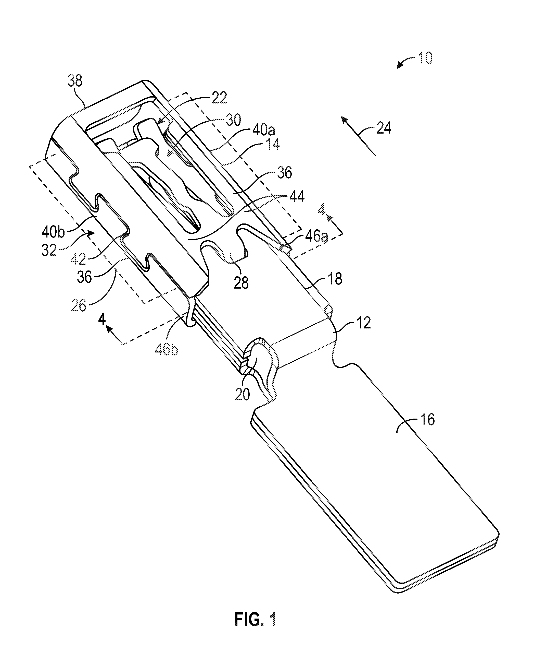
FIG. 1 is a perspective view of a first embodiment of an electrical terminal with a stabilized spring.
FIG. 2 is a perspective view of the electrical terminal from FIG. 1, shown from below.
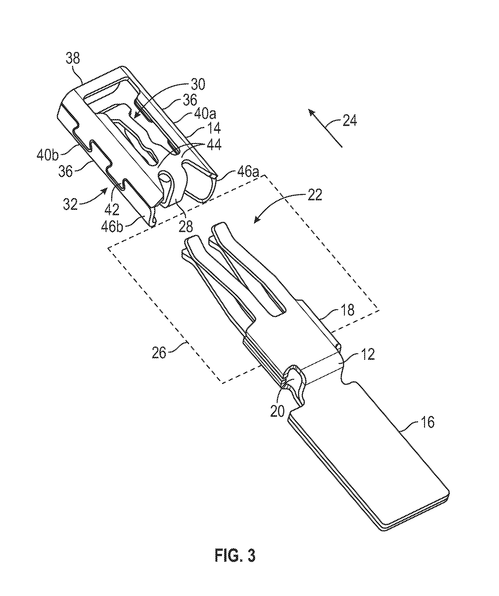
FIG. 3 is an exploded, perspective view of the electrical terminal from FIG. 1, showing a spring member separate from a contact member.
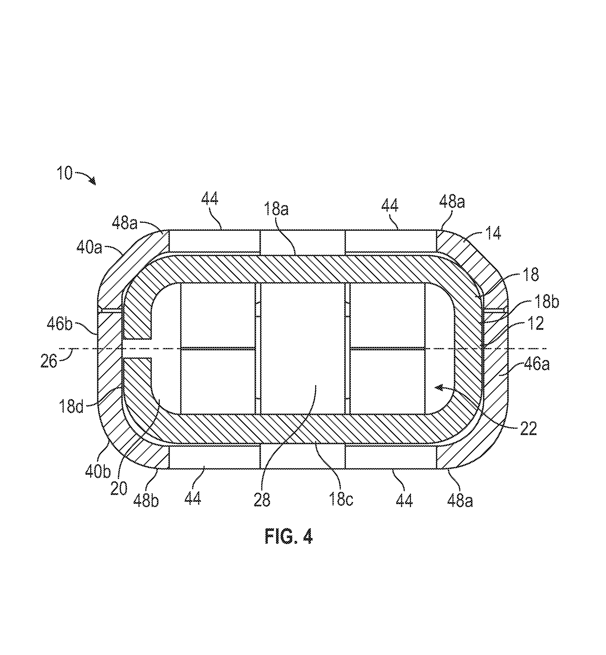
FIG. 4 is a cross-sectional view taken along the line 4-4 of FIG. 1.
FIG. 5 is a perspective view of a second embodiment of an electrical terminal with a stabilized spring.
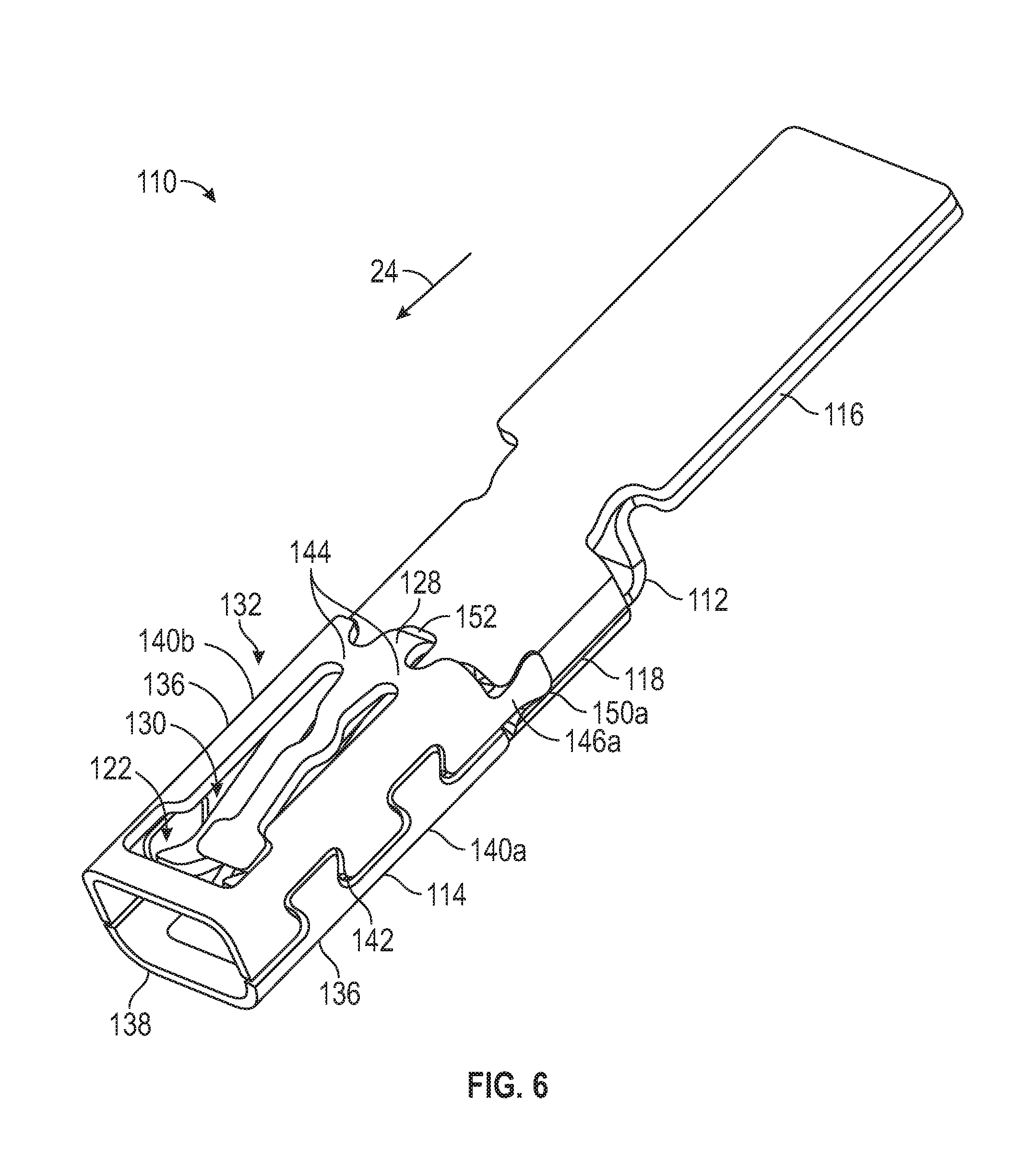
FIG. 6 is a perspective view of the electrical terminal from FIG. 5, shown from below.
FIG. 7 is an exploded, perspective view of the electrical terminal from FIG. 5, showing a spring member removed from a contact member.
DETAILED DESCRIPTION OF THE PREFERRED EMBODIMENTS
Referring now to the drawings, there is illustrated in FIG. 1 a first embodiment of an electrical terminal assembly, indicated generally at 10, in accordance with this invention. The illustrated electrical terminal assembly 10 is a female electrical terminal, but may be any desired type of terminal. The electrical terminal assembly 10 includes a contact member, indicated generally at 12, and a spring member, indicated generally at 14. FIG. 2 is a perspective view of the electrical terminal assembly 10, taken from below. FIG. 3 is a view similar to FIG. 1, showing the electrical terminal assembly 10 exploded with contact member 12 and the spring member 14 separated from each other. Details of the electrical terminal assembly 10 will be described in reference to these figures.
The illustrated contact member 12 is made from a single sheet of material, stamped and folded into the illustrated configuration. However, the contact member 12 may be made by any desired process. The illustrated contact member 12 is made of aluminum, but may be made of any desired material. Preferably, the contact member 12 is made of a material with good electrical conductivity, such as copper or a copper alloy.
The contact member 12 includes a connection portion 16 that is configured to be connected to a conductor such as a wire (not shown). The connection portion 16 may be configured for any desired type of connection. The contact member 12 includes a contact base 18 that is connected to the connection portion 16. The illustrated contact base 18 is a substantially rectangular cross-sectional shaped box that defines an interior space 20. However, the contact base 18 may have any desired shape.
The contact member 12 includes a plurality of contact arms, indicated generally at 22, that extend from the contact base 18 in an arm direction 24. In the illustrated embodiment, the connection portion 16 and the contact arms 22 are located on opposite sides of the contact base 18, but the components may have any desired relative orientations. The contact arms 22 are arranged on opposed sides of a terminal plane 26. In the illustrated embodiment, the contact member 12 includes a total of four contact arms 22 but the contact member 12 may have any desired number and arrangement of contact arms 22.
The electrical terminal assembly 10 is configured to mate with a corresponding terminal (not shown). In the illustrated embodiment, the corresponding terminal is a blade-type male terminal. However, the electrical terminal assembly 10 may be configured to mate with any desired type of corresponding terminal. When the electrical terminal assembly 10 is mated with the corresponding terminal, the corresponding terminal will be located on the terminal plane 26, between the contact arms 22.
The illustrated spring member 14 is made from a single sheet of material, stamped and folded into the illustrated configuration. However, the spring member 14 may be made by any desired process. The illustrated spring member 14 is made of stainless steel, but may be made of any desired material. Preferably, the spring member 14 is made of a material with good spring characteristics even at relatively high temperatures.
The spring member 14 includes a spring base 28. In the illustrated embodiment, when the electrical terminal assembly 10 is assembled (as shown in FIG. 1), the spring base 28 is located at least partially in the interior space 20 of the contact base 18. The spring member 14 includes a plurality of spring arms, indicated generally at 30, that extend from the spring base 28 in the arm direction 24. The spring arms 30 are arranged on opposed sides of the terminal plane 26. In the illustrated embodiment, the spring member 14 includes two spring arms 30 but the spring member 14 may have any desired number and arrangement of spring arms 30.
The spring member 14 includes a shroud, indicated generally at 32. The shroud 32 serves to protect the contact arms 22 and extends around and beyond the contact arms 22 when the electrical terminal assembly 10 is assembled. The illustrated shroud 32 includes two side shields 36 that are located on opposed sides of the contact arms 22, and pass through the terminal plane 26. The illustrated shroud 32 also includes an end shield 38 that is located beyond the contact arms 22 in the arm direction 24. The illustrated shroud 32 includes a first shroud portion 40a and a second shroud portion 40b that are substantially located on opposed sides of the terminal plane 26. In the illustrated embodiment, approximately half of each side shield 36 is located on the first shroud portion 40a and the other half is located on the second shroud portion 40b. Additionally, half of the end shield 38 is located on the first shroud portion 40a and the other half is located on the second shroud portion 40b. However, the shroud 32 may have a different configuration or arrangement of parts from that illustrated, if desired.
The first shroud portion 40a and the second shroud portion 40b are connected together by locks 42 on the side shields 36. The illustrated locks 42 are dovetail locks, but may be any desired connection.
The shroud 32 is connected to the spring base 28 by a plurality of shroud connectors 44. The illustrated shroud 32 includes four shroud connectors 44, two on either side of the terminal plane 26 and each shroud portion 40a and 40b is connected to the spring base 28 by two shroud connectors 44. The illustrated shroud connectors 44 extend from the spring base 28 to the shroud 32 substantially parallel to the terminal plane 26 and are located adjacent to the contact base 18 when the electrical terminal assembly 10 is assembled. However, the shroud connectors 44 may have any desired orientation and positioning.
The shroud 32 includes a first shroud extension 46a and a second shroud extension 46b. The shroud extensions 46a and 46b engage the contact base 18 to stabilize the spring member 14 relative to the contact member 12. The shroud extensions 46a and 46b extend from the side shields 36 opposite the arm direction 24. The illustrated shroud extensions 46a and 46b extend past the shroud connector 44 opposite the arm direction 24. Additionally, the illustrated shroud extensions 46a and 46b extend opposite the arm direction 24 past the spring base 28.
Referring to FIG. 4, a cross-sectional view taken along the line 4-4 of FIG. 1 is illustrated. The cross-section shows the contact base 18 and the shroud extensions 46a and 46b. As previously-described, the contact base 18 has a generally rectangular box-shape. The illustrated contact base 18 has rounded corners, but the contact base 18 may have any desired shape. The first shroud extension 46a includes flanges 48a and engages a first side 18a, a second side 18b, and a third side 18c of the contact base 18. The second shroud extension 46b includes flanges 48b and engages the first side 18a, the third side 18c, and a fourth side 18d of the contact base 18. By engaging multiple sides of the contact base 18, the shroud extensions 46a and 46b are better able to stabilize the spring member 14 relative to the contact member 12.
Referring to FIG. 5, there is illustrated a perspective view of a second embodiment of an electrical terminal assembly, indicated generally at 110, in accordance with this invention. FIG. 6 is a perspective view of the electrical terminal assembly 110 taken from below, and FIG. 7 is a view similar to FIG. 5, showing the electrical terminal assembly 110 exploded. The electrical terminal assembly 110 is substantially the same as the previously-described electrical terminal assembly 10. Similar features are identified by the same reference number increased by 100 and will not be described in detail.
The electrical terminal assembly 110 includes a shroud 132. The shroud 132 includes a first shroud extension 146a and a second shroud extension 146b. The shroud extensions 146a and 146b engage a contact base 118 to stabilize a spring member 114 relative to a contact member 112. The shroud extensions 146a and 146b extend from side shields 136 opposite an arm direction 124. The illustrated shroud extensions 146a and 146b are tapered projections that extend opposite the arm direction 124.
The contact base 118 defines a first slot 150a and a second slot 150b on opposed sides of the contact base 118. The first shroud extension 146a is located in the first slot 150a and the second shroud extension 146b is located in the second slot 150b. In the illustrated embodiment, a terminal plane 126 passes through the first slot 150a and the second slot 150b. Additionally, the first shroud extension 146a and the second shroud extension 146b are located at least partially on the terminal plane.
The electrical terminal assembly 110 includes an optional space 152 between a spring base 128 and the contact base 118. The space 152 allows the first shroud extension 146a to be positioned in the first slot 150a and the second shroud extension 146b to be positioned in the second slot 150b without the spring base 128 engaging the contact base body 118 and controlling control the positioning of the spring member 114 relative to the contact member 112.
The principle and mode of operation of this invention have been explained and illustrated in its preferred embodiments. However, it must be understood that this invention may be practiced otherwise than as specifically explained and illustrated without departing from its spirit or scope.
* * * * *
D00000
D00001
D00002
D00003
D00004
D00005
D00006
D00007
XML
uspto.report is an independent third-party trademark research tool that is not affiliated, endorsed, or sponsored by the United States Patent and Trademark Office (USPTO) or any other governmental organization. The information provided by uspto.report is based on publicly available data at the time of writing and is intended for informational purposes only.
While we strive to provide accurate and up-to-date information, we do not guarantee the accuracy, completeness, reliability, or suitability of the information displayed on this site. The use of this site is at your own risk. Any reliance you place on such information is therefore strictly at your own risk.
All official trademark data, including owner information, should be verified by visiting the official USPTO website at www.uspto.gov. This site is not intended to replace professional legal advice and should not be used as a substitute for consulting with a legal professional who is knowledgeable about trademark law.