Surgical stapling instruments with linear position assembly
Hryb , et al. Ja
U.S. patent number 10,190,888 [Application Number 15/053,599] was granted by the patent office on 2019-01-29 for surgical stapling instruments with linear position assembly. This patent grant is currently assigned to Covidien LP. The grantee listed for this patent is Covidien LP. Invention is credited to Anthony Calderoni, Ethan Collins, Joseph Decker, Luis Dussan, John Hryb.


| United States Patent | 10,190,888 |
| Hryb , et al. | January 29, 2019 |
Surgical stapling instruments with linear position assembly
Abstract
A surgical stapling instrument includes an elongate body, a cartridge assembly, an anvil assembly, and a linear position assembly including a pair of opposing magnets, and a plurality of sensors. The elongate body has a central shaft longitudinally translatable therethrough. The cartridge assembly is coupled to a distal end of the elongate body. The anvil assembly is selectively connectable to the central shaft of the elongate body. The magnets are mounted to the central shaft. The sensors are fixed within the cartridge assembly and configured to sense a change in a magnetic field of the magnets upon a longitudinal movement of the magnets in response to an actuation of the central shaft to determine a linear position of the anvil assembly relative to the staple cartridge.
| Inventors: | Hryb; John (Cheshire, CT), Collins; Ethan (Naugatuck, CT), Dussan; Luis (East Haven, CT), Decker; Joseph (Southington, CT), Calderoni; Anthony (Bristol, CT) | ||||||||||
|---|---|---|---|---|---|---|---|---|---|---|---|
| Applicant: |
|
||||||||||
| Assignee: | Covidien LP (Mansfield,
MA) |
||||||||||
| Family ID: | 56886549 | ||||||||||
| Appl. No.: | 15/053,599 | ||||||||||
| Filed: | February 25, 2016 |
Prior Publication Data
| Document Identifier | Publication Date | |
|---|---|---|
| US 20160265938 A1 | Sep 15, 2016 | |
Related U.S. Patent Documents
| Application Number | Filing Date | Patent Number | Issue Date | ||
|---|---|---|---|---|---|
| 62131278 | Mar 11, 2015 | ||||
| Current U.S. Class: | 1/1 |
| Current CPC Class: | G01D 5/145 (20130101); A61B 17/07207 (20130101); A61B 17/1155 (20130101); A61B 17/072 (20130101); A61B 2017/00017 (20130101); A61B 2017/00876 (20130101); A61B 17/115 (20130101); A61B 2017/00398 (20130101); A61B 17/068 (20130101); A61B 2017/07214 (20130101); A61B 2017/00039 (20130101); A61B 90/98 (20160201); A61B 2017/00119 (20130101); A61B 2090/0811 (20160201) |
| Current International Class: | A61B 17/072 (20060101); G01D 5/14 (20060101); A61B 90/00 (20160101); A61B 17/068 (20060101); A61B 17/115 (20060101); A61B 17/00 (20060101); A61B 90/98 (20160101) |
| Field of Search: | ;227/19,175.1,175.2,175.3,176.1,180.1 ;606/139,151,219,153 |
References Cited [Referenced By]
U.S. Patent Documents
| 2777340 | January 1957 | Hettwer et al. |
| 2957353 | October 1960 | Babacz |
| 3111328 | November 1963 | Di Rito et al. |
| 3695058 | October 1972 | Keith, Jr. |
| 3734515 | May 1973 | Dudek |
| 3759336 | September 1973 | Marcovitz et al. |
| 4162399 | July 1979 | Hudson |
| 4606343 | August 1986 | Conta et al. |
| 4705038 | November 1987 | Sjostrom et al. |
| 4722685 | February 1988 | de Estrada et al. |
| 4823807 | April 1989 | Russell et al. |
| 4874181 | October 1989 | Hsu |
| 5129118 | July 1992 | Walmesley |
| 5129570 | July 1992 | Schulze et al. |
| 5152744 | October 1992 | Krause et al. |
| 5301061 | April 1994 | Nakada et al. |
| 5312023 | May 1994 | Green et al. |
| 5326013 | July 1994 | Green et al. |
| 5350355 | September 1994 | Sklar |
| 5383874 | January 1995 | Jackson et al. |
| 5383880 | January 1995 | Hooven |
| 5389098 | February 1995 | Tsuruta et al. |
| 5395033 | March 1995 | Byrne et al. |
| 5400267 | March 1995 | Denen et al. |
| 5411508 | May 1995 | Bessler et al. |
| 5413267 | May 1995 | Solyntjes et al. |
| 5427087 | June 1995 | Ito et al. |
| 5433721 | July 1995 | Hooven et al. |
| 5467911 | November 1995 | Tsuruta et al. |
| 5476379 | December 1995 | Disel |
| 5487499 | January 1996 | Sorrentino et al. |
| 5518163 | May 1996 | Hooven |
| 5518164 | May 1996 | Hooven |
| 5526822 | June 1996 | Burbank et al. |
| 5529235 | June 1996 | Boiarski et al. |
| 5535934 | July 1996 | Boiarski et al. |
| 5535937 | July 1996 | Boiarski et al. |
| 5540375 | July 1996 | Bolanos et al. |
| 5540706 | July 1996 | Aust et al. |
| 5542594 | August 1996 | McKean et al. |
| 5549637 | August 1996 | Crainich |
| 5553675 | September 1996 | Pitzen et al. |
| 5562239 | October 1996 | Boiarski et al. |
| 5564615 | October 1996 | Bishop et al. |
| 5609560 | March 1997 | Ichikawa et al. |
| 5626587 | May 1997 | Bishop et al. |
| 5632432 | May 1997 | Schulze et al. |
| 5645209 | July 1997 | Green et al. |
| 5647526 | July 1997 | Green et al. |
| 5653374 | August 1997 | Young et al. |
| 5658300 | August 1997 | Bito et al. |
| 5662662 | September 1997 | Bishop et al. |
| 5667517 | September 1997 | Hooven |
| 5693042 | December 1997 | Boiarski et al. |
| 5704534 | January 1998 | Huitema et al. |
| 5713505 | February 1998 | Huitema |
| 5762603 | June 1998 | Thompson |
| 5779130 | July 1998 | Alesi et al. |
| 5782396 | July 1998 | Mastri et al. |
| 5782397 | July 1998 | Koukline |
| 5792573 | August 1998 | Pitzen et al. |
| 5797536 | August 1998 | Smith et al. |
| 5820009 | October 1998 | Melling et al. |
| 5863159 | January 1999 | Lasko |
| 5908427 | June 1999 | McKean et al. |
| 5954259 | September 1999 | Viola et al. |
| 5964774 | October 1999 | McKean et al. |
| 5993454 | November 1999 | Longo |
| 6010054 | January 2000 | Johnson et al. |
| 6017354 | January 2000 | Culp et al. |
| 6032849 | March 2000 | Mastri et al. |
| 6045560 | April 2000 | McKean et al. |
| 6090123 | July 2000 | Culp et al. |
| 6126651 | October 2000 | Mayer |
| 6129547 | October 2000 | Cise et al. |
| 6165169 | December 2000 | Panescu et al. |
| 6239732 | May 2001 | Cusey |
| 6241139 | June 2001 | Milliman et al. |
| 6264086 | July 2001 | McGuckin, Jr. |
| 6264087 | July 2001 | Whitman |
| 6302311 | October 2001 | Adams et al. |
| 6315184 | November 2001 | Whitman |
| 6321855 | November 2001 | Barnes |
| 6329778 | December 2001 | Culp et al. |
| 6343731 | February 2002 | Adams et al. |
| 6348061 | February 2002 | Whitman |
| 6368324 | April 2002 | Dinger et al. |
| 6371909 | April 2002 | Hoeg et al. |
| 6434507 | August 2002 | Clayton et al. |
| 6443973 | September 2002 | Whitman |
| 6461372 | October 2002 | Jensen et al. |
| 6488197 | December 2002 | Whitman |
| 6491201 | December 2002 | Whitman |
| 6533157 | March 2003 | Whitman |
| 6537280 | March 2003 | Dinger et al. |
| 6610066 | August 2003 | Dinger et al. |
| 6611793 | August 2003 | Burnside et al. |
| 6645218 | November 2003 | Cassidy et al. |
| 6654999 | December 2003 | Stoddard et al. |
| 6698643 | March 2004 | Whitman |
| 6699177 | March 2004 | Wang et al. |
| 6716233 | April 2004 | Whitman |
| 6743240 | June 2004 | Smith et al. |
| 6783533 | August 2004 | Green et al. |
| 6792390 | September 2004 | Burnside et al. |
| 6793652 | September 2004 | Whitman et al. |
| 6817508 | November 2004 | Racenet et al. |
| 6830174 | December 2004 | Hillstead et al. |
| 6846308 | January 2005 | Whitman et al. |
| 6846309 | January 2005 | Whitman et al. |
| 6849071 | February 2005 | Whitman et al. |
| 6860892 | March 2005 | Tanaka et al. |
| 6899538 | May 2005 | Matoba |
| 6905057 | June 2005 | Swayze et al. |
| 6959852 | November 2005 | Shelton, IV et al. |
| 6964363 | November 2005 | Wales et al. |
| 6981628 | January 2006 | Wales |
| 6981941 | January 2006 | Whitman et al. |
| 6986451 | January 2006 | Mastri et al. |
| 6988649 | January 2006 | Shelton, IV et al. |
| 7032798 | April 2006 | Whitman et al. |
| RE39152 | June 2006 | Aust et al. |
| 7055731 | June 2006 | Shelton, IV et al. |
| 7059508 | June 2006 | Shelton, IV et al. |
| 7077856 | July 2006 | Whitman |
| 7111769 | September 2006 | Wales et al. |
| 7122029 | October 2006 | Koop et al. |
| 7140528 | November 2006 | Shelton, IV |
| 7141049 | November 2006 | Stern et al. |
| 7143923 | December 2006 | Shelton, IV et al. |
| 7143925 | December 2006 | Shelton, IV et al. |
| 7143926 | December 2006 | Shelton, IV et al. |
| 7147138 | December 2006 | Shelton, IV |
| 7172104 | February 2007 | Scirica et al. |
| 7225964 | June 2007 | Mastri et al. |
| 7238021 | July 2007 | Johnson |
| 7246734 | July 2007 | Shelton, IV |
| 7252660 | August 2007 | Kunz |
| 7328828 | February 2008 | Ortiz et al. |
| 7364061 | April 2008 | Swayze et al. |
| 7380695 | June 2008 | Doll et al. |
| 7380696 | June 2008 | Shelton, IV et al. |
| 7404508 | July 2008 | Smith et al. |
| 7407078 | August 2008 | Shelton, IV et al. |
| 7416101 | August 2008 | Shelton, IV et al. |
| 7419080 | September 2008 | Smith et al. |
| 7422139 | September 2008 | Shelton, IV et al. |
| 7431189 | October 2008 | Shelton, IV et al. |
| 7441684 | October 2008 | Shelton, IV et al. |
| 7448525 | November 2008 | Shelton, IV et al. |
| 7464846 | December 2008 | Shelton, IV et al. |
| 7464847 | December 2008 | Viola et al. |
| 7464849 | December 2008 | Shelton, IV et al. |
| 7481347 | January 2009 | Roy |
| 7481824 | January 2009 | Boudreaux et al. |
| 7487899 | February 2009 | Shelton, IV et al. |
| 7549564 | June 2009 | Boudreaux |
| 7565993 | July 2009 | Milliman et al. |
| 7568603 | August 2009 | Shelton, IV et al. |
| 7575144 | August 2009 | Ortiz et al. |
| 7588175 | September 2009 | Timm et al. |
| 7588176 | September 2009 | Timm et al. |
| 7637409 | December 2009 | Marczyk |
| 7641093 | January 2010 | Doll et al. |
| 7644848 | January 2010 | Swayze et al. |
| 7670334 | March 2010 | Hueil et al. |
| 7673780 | March 2010 | Shelton, IV et al. |
| 7699835 | April 2010 | Lee et al. |
| 7721931 | May 2010 | Shelton, IV et al. |
| 7738971 | June 2010 | Swayze et al. |
| 7740159 | June 2010 | Shelton, IV et al. |
| 7743960 | June 2010 | Whitman et al. |
| 7758613 | July 2010 | Whitman |
| 7766210 | August 2010 | Shelton, IV et al. |
| 7770773 | August 2010 | Whitman et al. |
| 7770775 | August 2010 | Shelton, IV et al. |
| 7793812 | September 2010 | Moore et al. |
| 7799039 | September 2010 | Shelton, IV et al. |
| 7802712 | September 2010 | Milliman et al. |
| 7803151 | September 2010 | Whitman |
| 7822458 | October 2010 | Webster, III et al. |
| 7845534 | December 2010 | Viola et al. |
| 7845537 | December 2010 | Shelton, IV et al. |
| 7857185 | December 2010 | Swayze et al. |
| 7870989 | January 2011 | Viola et al. |
| 7900805 | March 2011 | Shelton, IV et al. |
| 7905897 | March 2011 | Whitman et al. |
| 7918230 | April 2011 | Whitman et al. |
| 7922061 | April 2011 | Shelton, IV et al. |
| 7922719 | April 2011 | Ralph et al. |
| 7947034 | May 2011 | Whitman |
| 7951071 | May 2011 | Whitman et al. |
| 7954682 | June 2011 | Giordano et al. |
| 7959051 | June 2011 | Smith et al. |
| 7963433 | June 2011 | Whitman et al. |
| 7967178 | June 2011 | Scirica et al. |
| 7967179 | June 2011 | Olson et al. |
| 7992758 | August 2011 | Whitman et al. |
| 8011550 | September 2011 | Aranyi et al. |
| 8016178 | September 2011 | Olson et al. |
| 8016855 | September 2011 | Whitman et al. |
| 8020743 | September 2011 | Shelton, IV |
| 8025199 | September 2011 | Whitman et al. |
| 8035487 | October 2011 | Malackowski |
| 8052024 | November 2011 | Viola et al. |
| 8114118 | February 2012 | Knodel et al. |
| 8127975 | March 2012 | Olson et al. |
| 8132705 | March 2012 | Viola et al. |
| 8152516 | April 2012 | Harvey et al. |
| 8157150 | April 2012 | Viola et al. |
| 8157151 | April 2012 | Ingmanson et al. |
| 8182494 | May 2012 | Yencho et al. |
| 8186555 | May 2012 | Shelton, IV et al. |
| 8186587 | May 2012 | Zmood et al. |
| 8220367 | July 2012 | Hsu |
| 8235273 | August 2012 | Olson et al. |
| 8241322 | August 2012 | Whitman et al. |
| 8272554 | September 2012 | Whitman et al. |
| 8292150 | October 2012 | Bryant |
| 8292888 | October 2012 | Whitman |
| 8342379 | January 2013 | Whitman et al. |
| 8348130 | January 2013 | Shah et al. |
| 8348855 | January 2013 | Hillely et al. |
| 8353440 | January 2013 | Whitman et al. |
| 8357144 | January 2013 | Whitman et al. |
| 8365633 | February 2013 | Simaan et al. |
| 8365972 | February 2013 | Aranyi et al. |
| 8371492 | February 2013 | Aranyi et al. |
| 8372057 | February 2013 | Cude et al. |
| 8391957 | March 2013 | Carlson et al. |
| 8403926 | March 2013 | Nobis et al. |
| 8418904 | April 2013 | Wenchell et al. |
| 8424739 | April 2013 | Racenet et al. |
| 8454585 | June 2013 | Whitman |
| 8505802 | August 2013 | Viola et al. |
| 8517241 | August 2013 | Nicholas et al. |
| 8523043 | September 2013 | Ullrich et al. |
| 8551076 | October 2013 | Duval et al. |
| 8561871 | October 2013 | Rajappa et al. |
| 8561874 | October 2013 | Scirica |
| 8602287 | December 2013 | Yates et al. |
| 8623000 | January 2014 | Humayun et al. |
| 8627995 | January 2014 | Smith et al. |
| 8632463 | January 2014 | Drinan et al. |
| 8636766 | January 2014 | Milliman et al. |
| 8647258 | February 2014 | Aranyi et al. |
| 8652121 | February 2014 | Quick et al. |
| 8657174 | February 2014 | Yates et al. |
| 8657177 | February 2014 | Scirica et al. |
| 8672206 | March 2014 | Aranyi et al. |
| 8696552 | April 2014 | Whitman |
| 8708213 | April 2014 | Shelton, IV et al. |
| 8715306 | May 2014 | Faller et al. |
| 8733614 | May 2014 | Ross |
| 8758391 | June 2014 | Swayze et al. |
| 8806973 | August 2014 | Ross et al. |
| 8808311 | August 2014 | Heinrich et al. |
| 8820605 | September 2014 | Shelton, IV |
| 8851355 | October 2014 | Aranyi et al. |
| 8858571 | October 2014 | Shelton, IV et al. |
| 8875972 | November 2014 | Weisenburgh, II et al. |
| 8888762 | November 2014 | Whitman |
| 8893946 | November 2014 | Boudreaux et al. |
| 8899462 | December 2014 | Kostrzewski et al. |
| 8905289 | December 2014 | Patel et al. |
| 8919630 | December 2014 | Milliman |
| 8931680 | January 2015 | Milliman |
| 8939344 | January 2015 | Olson et al. |
| 8950646 | February 2015 | Viola |
| 8960519 | February 2015 | Whitman et al. |
| 8961396 | February 2015 | Azarbarzin et al. |
| 8967443 | March 2015 | McCuen |
| 8968276 | March 2015 | Zemlok et al. |
| 8968337 | March 2015 | Whitfield et al. |
| 8992422 | March 2015 | Spivey et al. |
| 9016545 | April 2015 | Aranyi et al. |
| 9023014 | May 2015 | Chowaniec et al. |
| 9033868 | May 2015 | Whitman et al. |
| 9055943 | June 2015 | Zemlok et al. |
| 9064653 | June 2015 | Prest et al. |
| 9072515 | July 2015 | Hall et al. |
| 9113847 | August 2015 | Whitman et al. |
| 9113875 | August 2015 | Viola et al. |
| 9113876 | August 2015 | Zemlok et al. |
| 9113899 | August 2015 | Garrison et al. |
| 9241712 | January 2016 | Zemlok et al. |
| 9282961 | March 2016 | Whitman et al. |
| 9307986 | April 2016 | Hall et al. |
| 2001/0031975 | October 2001 | Whitman et al. |
| 2002/0049454 | April 2002 | Whitman et al. |
| 2002/0165541 | November 2002 | Whitman |
| 2003/0038938 | February 2003 | Jung et al. |
| 2003/0073981 | April 2003 | Whitman |
| 2003/0165794 | September 2003 | Matoba |
| 2004/0111012 | June 2004 | Whitman |
| 2004/0133189 | July 2004 | Sakurai |
| 2004/0153124 | August 2004 | Whitman |
| 2004/0176751 | September 2004 | Weitzner et al. |
| 2004/0193146 | September 2004 | Lee et al. |
| 2005/0125027 | June 2005 | Knodel et al. |
| 2005/0131442 | June 2005 | Yachia et al. |
| 2006/0142656 | June 2006 | Malackowski et al. |
| 2006/0142740 | June 2006 | Sherman et al. |
| 2006/0142744 | June 2006 | Boutoussov |
| 2006/0259073 | November 2006 | Miyamoto et al. |
| 2006/0273135 | December 2006 | Beetel |
| 2006/0278680 | December 2006 | Viola et al. |
| 2006/0284730 | December 2006 | Schmid et al. |
| 2007/0023476 | February 2007 | Whitman et al. |
| 2007/0023477 | February 2007 | Whitman et al. |
| 2007/0029363 | February 2007 | Popov |
| 2007/0084897 | April 2007 | Shelton et al. |
| 2007/0102472 | May 2007 | Shelton |
| 2007/0152014 | July 2007 | Gillum et al. |
| 2007/0175947 | August 2007 | Ortiz et al. |
| 2007/0175949 | August 2007 | Shelton et al. |
| 2007/0175950 | August 2007 | Shelton et al. |
| 2007/0175951 | August 2007 | Shelton et al. |
| 2007/0175955 | August 2007 | Shelton et al. |
| 2007/0175961 | August 2007 | Shelton et al. |
| 2007/0270784 | November 2007 | Smith et al. |
| 2008/0029570 | February 2008 | Shelton et al. |
| 2008/0029573 | February 2008 | Shelton et al. |
| 2008/0029574 | February 2008 | Shelton et al. |
| 2008/0029575 | February 2008 | Shelton et al. |
| 2008/0058801 | March 2008 | Taylor et al. |
| 2008/0109012 | May 2008 | Falco et al. |
| 2008/0110958 | May 2008 | McKenna et al. |
| 2008/0147089 | June 2008 | Loh et al. |
| 2008/0167736 | July 2008 | Swayze et al. |
| 2008/0185419 | August 2008 | Smith et al. |
| 2008/0188841 | August 2008 | Tomasello et al. |
| 2008/0197167 | August 2008 | Viola et al. |
| 2008/0208195 | August 2008 | Shores et al. |
| 2008/0237296 | October 2008 | Boudreaux et al. |
| 2008/0251561 | October 2008 | Eades et al. |
| 2008/0255413 | October 2008 | Zemlok et al. |
| 2008/0255607 | October 2008 | Zemlok |
| 2008/0262654 | October 2008 | Omori et al. |
| 2008/0283571 | November 2008 | Boyden |
| 2008/0308603 | December 2008 | Shelton et al. |
| 2009/0012533 | January 2009 | Barbagli et al. |
| 2009/0057369 | March 2009 | Smith |
| 2009/0090763 | April 2009 | Zemlok et al. |
| 2009/0099876 | April 2009 | Whitman |
| 2009/0138006 | May 2009 | Bales et al. |
| 2009/0171147 | July 2009 | Lee et al. |
| 2009/0182193 | July 2009 | Whitman et al. |
| 2009/0206132 | August 2009 | Hueil |
| 2009/0209990 | August 2009 | Yates et al. |
| 2009/0254094 | October 2009 | Knapp et al. |
| 2009/0299141 | December 2009 | Downey et al. |
| 2010/0023022 | January 2010 | Zeiner et al. |
| 2010/0065609 | March 2010 | Schwemberger |
| 2010/0069942 | March 2010 | Shelton, IV |
| 2010/0096435 | April 2010 | Fuchs |
| 2010/0193568 | August 2010 | Scheib et al. |
| 2010/0211053 | August 2010 | Ross et al. |
| 2010/0225073 | September 2010 | Porter et al. |
| 2011/0062211 | March 2011 | Ross |
| 2011/0071508 | March 2011 | Duval et al. |
| 2011/0077673 | March 2011 | Grubac et al. |
| 2011/0121049 | May 2011 | Malinouskas et al. |
| 2011/0125138 | May 2011 | Malinouskas et al. |
| 2011/0139851 | June 2011 | McCuen |
| 2011/0144640 | June 2011 | Heinrich |
| 2011/0155783 | June 2011 | Rajappa et al. |
| 2011/0155786 | June 2011 | Shelton, IV |
| 2011/0172648 | July 2011 | Jeong |
| 2011/0174009 | July 2011 | Iizuka et al. |
| 2011/0174099 | July 2011 | Ross et al. |
| 2011/0184245 | July 2011 | Xia et al. |
| 2011/0204119 | August 2011 | McCuen |
| 2011/0218522 | September 2011 | Whitman |
| 2011/0276057 | November 2011 | Conlon et al. |
| 2011/0290854 | December 2011 | Timm et al. |
| 2011/0295242 | December 2011 | Spivey et al. |
| 2011/0295269 | December 2011 | Swensgard et al. |
| 2012/0000962 | January 2012 | Racenet et al. |
| 2012/0074199 | March 2012 | Olson et al. |
| 2012/0089131 | April 2012 | Zemlok et al. |
| 2012/0104071 | May 2012 | Bryant |
| 2012/0143002 | June 2012 | Aranyi et al. |
| 2012/0172924 | July 2012 | Allen, IV |
| 2012/0211542 | August 2012 | Racenet |
| 2012/0223121 | September 2012 | Viola et al. |
| 2012/0253329 | October 2012 | Zemlok et al. |
| 2012/0292367 | November 2012 | Morgan |
| 2012/0310220 | December 2012 | Malkowski et al. |
| 2012/0323226 | December 2012 | Chowaniec et al. |
| 2013/0093149 | April 2013 | Saur et al. |
| 2013/0181035 | July 2013 | Milliman |
| 2013/0184704 | July 2013 | Beardsley et al. |
| 2013/0206814 | August 2013 | Morgan |
| 2013/0214025 | August 2013 | Zemlok et al. |
| 2013/0274722 | October 2013 | Kostrzewski et al. |
| 2013/0282052 | October 2013 | Aranyi et al. |
| 2013/0292451 | November 2013 | Viola et al. |
| 2013/0313304 | November 2013 | Shelton, IV et al. |
| 2013/0317486 | November 2013 | Nicholas et al. |
| 2013/0319706 | December 2013 | Nicholas et al. |
| 2013/0324978 | December 2013 | Nicholas et al. |
| 2013/0324979 | December 2013 | Nicholas et al. |
| 2013/0334281 | December 2013 | Williams |
| 2014/0001231 | January 2014 | Shelton, IV |
| 2014/0012236 | January 2014 | Williams et al. |
| 2014/0012237 | January 2014 | Pribanic et al. |
| 2014/0012289 | January 2014 | Snow et al. |
| 2014/0025046 | January 2014 | Williams et al. |
| 2014/0110455 | April 2014 | Ingmanson et al. |
| 2014/0110456 | April 2014 | Taylor |
| 2014/0166717 | June 2014 | Swayze |
| 2014/0207125 | July 2014 | Applegate et al. |
| 2014/0207182 | July 2014 | Zergiebel et al. |
| 2014/0207185 | July 2014 | Goble et al. |
| 2014/0236174 | August 2014 | Williams et al. |
| 2014/0263538 | September 2014 | Leimbach |
| 2014/0276932 | September 2014 | Williams et al. |
| 2014/0299647 | October 2014 | Scirica et al. |
| 2014/0303668 | October 2014 | Nicholas et al. |
| 2014/0358129 | December 2014 | Zergiebel et al. |
| 2014/0361068 | December 2014 | Aranyi et al. |
| 2014/0365235 | December 2014 | DeBoer et al. |
| 2014/0373652 | December 2014 | Zergiebel et al. |
| 2015/0014392 | January 2015 | Williams et al. |
| 2015/0048144 | February 2015 | Whitman |
| 2015/0076205 | March 2015 | Zergiebel |
| 2015/0080912 | March 2015 | Sapre |
| 2015/0083774 | March 2015 | Measamer |
| 2015/0112381 | April 2015 | Richard |
| 2015/0122870 | May 2015 | Zemlok et al. |
| 2015/0133224 | May 2015 | Whitman et al. |
| 2015/0150547 | June 2015 | Ingmanson et al. |
| 2015/0150574 | June 2015 | Richard et al. |
| 2015/0157320 | June 2015 | Zergiebel et al. |
| 2015/0157321 | June 2015 | Zergiebel et al. |
| 2015/0164502 | June 2015 | Richard et al. |
| 2015/0201931 | July 2015 | Zergiebel et al. |
| 2015/0342601 | December 2015 | Williams et al. |
| 2451558 | Jan 2003 | CA | |||
| 102247182 | Nov 2011 | CN | |||
| 102008053842 | May 2010 | DE | |||
| 0705571 | Apr 1996 | EP | |||
| 1769754 | Apr 2007 | EP | |||
| 2316345 | May 2011 | EP | |||
| 2668910 | Dec 2013 | EP | |||
| 2333509 | Feb 2010 | ES | |||
| 2005-125075 | May 2005 | JP | |||
| 20120022521 | Mar 2012 | KR | |||
| 2011/108840 | Sep 2011 | WO | |||
| 2012/040984 | Apr 2012 | WO | |||
Other References
|
Extended European Search Report corresponding to counterpart International Application No. EP 14 18 4882.0 dated May 12, 2015. cited by applicant . Canadian Office Action corresponding to counterpart International Application No. CA 2640399 dated May 7, 2015. cited by applicant . Japanese Office Action corresponding to counterpart International Application No. JP 2011-197365 dated Mar. 23, 2015. cited by applicant . Japanese Office Action corresponding to counterpart International Application No. JP 2011-084092 dated May 20, 2015. cited by applicant . Japanese Office Action corresponding to counterpart International Application No. JP 2014-148482 dated Jun. 2, 2015. cited by applicant . Extended European Search Report corresponding to counterpart International Application No. EP 14 18 9358.6 dated Jul. 8, 2015. cited by applicant . Extended European Search Report corresponding to counterpart International Application No. EP 14 19 6148.2 dated Apr. 23, 2015. cited by applicant . Partial European Search Report corresponding to counterpart International Application No. EP 14 19 6704.2 dated May 11, 2015. cited by applicant . Australian Office Action corresponding to counterpart International Application No. AU 2010241367 dated Aug. 20, 2015. cited by applicant . Partial European Search Report corresponding to counterpart International Application No. EP 14 19 9783.3 dated Sep. 3, 2015. cited by applicant . Extended European Search Report corresponding to counterpart International Application No. EP 15 16 9962.6 dated Sep. 14, 2015. cited by applicant. |
Primary Examiner: Smith; Scott A.
Parent Case Text
CROSS-REFERENCE TO RELATED APPLICATIONS
This application claims the benefit of and priority to U.S. Provisional Patent Application Ser. No. 62/131,278 filed Mar. 11, 2015, the entire disclosure of which is incorporated by reference herein.
Claims
What is claimed is:
1. A surgical stapling instrument, comprising: an elongate body having a proximal end and a distal end, the elongate body including a longitudinally translatable central shaft; a cartridge assembly coupled to the distal end of the elongate body and defining a longitudinal axis, the cartridge assembly including a staple cartridge; an anvil assembly selectively connectable to a distal end of the central shaft; and a linear position assembly including: a pair of opposing magnets mounted to the central shaft, wherein each magnet generates a magnetic field, the pair of opposing magnets each having a north pole and a south pole and being oriented such that the north poles of the pair of opposing magnets are adjacent one another or the south poles of the pair of opposing magnets are adjacent one another; and a plurality of sensors fixed within the cartridge assembly and configured to sense a change in the magnetic fields upon a longitudinal movement of the pair of opposing magnets in response to an actuation of the central shaft to determine a linear position of the anvil assembly along the longitudinal axis relative to the staple cartridge.
2. The surgical stapling instrument according to claim 1, wherein the plurality of sensors is at least one of: at least three magnetoresistance sensors; or at least three hall-effect sensors.
3. The surgical stapling instrument according to claim 2, wherein the plurality of sensors is axially aligned with one another along the longitudinal axis of the cartridge assembly.
4. The surgical stapling instrument according to claim 1, wherein the plurality of sensors is laterally offset and parallel with the pair of opposing magnets.
5. The surgical stapling instrument according to claim 1, wherein the linear position assembly further includes a micro-controller in electrical communication with the plurality of sensors, the micro-controller configured to determine the linear position of the anvil assembly along the longitudinal axis relative to the staple cartridge.
6. The surgical stapling instrument according to claim 5, wherein the micro-controller is configured to determine the linear position of the anvil assembly by: determining a linear position of the plurality of magnets relative to each sensor of the plurality of sensors; determining which sensor of the plurality of sensors has a highest peak-to-peak voltage value; and determining which sensor of the plurality of sensors has a second highest peak-to-peak voltage value.
7. The surgical stapling instrument according to claim 1, wherein the linear position assembly further includes a chip assembly at least partially disposed within the cartridge assembly and having the plurality of sensors fixed thereto.
8. A method of determining a linear position of a component of a surgical stapling instrument, comprising: providing a surgical stapling instrument including: an elongate body having a proximal end and a distal end, the elongate body including a longitudinally translatable central shaft; a cartridge assembly coupled to the distal end of the elongate body and defining a longitudinal axis, the cartridge assembly including a staple cartridge; an anvil assembly selectively connectable to a distal end of the central shaft of the elongate body; and a linear position assembly including: a pair of opposing magnets mounted to the central shaft, wherein each magnet generates a magnetic field; and a plurality of sensors fixed within the cartridge assembly; sensing, via the plurality of sensors, longitudinal movement of the pair of opposing magnets upon actuation of the central shaft; and determining a linear position of the anvil assembly relative to the staple cartridge along the longitudinal axis, wherein determining the linear position of the anvil assembly includes: determining a linear position of the plurality of magnets relative to each sensor of the plurality of sensors; determining which sensor of the plurality of sensors has a highest peak-to-peak voltage value; and determining which sensor of the plurality of sensors has a second highest peak-to-peak voltage value.
9. The method according to claim 8, further comprising at least one of: determining an angle of direction of the magnetic field emitted by the pair of opposing magnets; or determining a magnetic flux density of the magnetic field emitted by the pair of opposing magnets.
10. The method according to claim 8, wherein the pair of opposing magnets are in the form of two magnetic bars each having a north pole and a south pole, the two magnetic bars being oriented such that the north poles of the two magnetic bars are adjacent one another or the south poles of the two magnetic bars are adjacent one another.
11. The method according to claim 8, wherein determining the linear position of the anvil assembly includes determining a linear position of an anvil head of the anvil assembly relative to a distal end of the staple cartridge.
12. A surgical stapling instrument, comprising: an elongate body having a proximal end and a distal end, the elongate body including a longitudinally translatable central shaft; a cartridge assembly coupled to the distal end of the elongate body and defining a longitudinal axis, the cartridge assembly including a staple cartridge; an anvil assembly selectively connectable to a distal end of the central shaft; and a linear position assembly including: a pair of opposing magnets mounted to the central shaft, wherein each magnet generates a magnetic field; a plurality of sensors fixed within the cartridge assembly and configured to sense a change in the magnetic fields upon a longitudinal movement of the pair of opposing magnets in response to an actuation of the central shaft to determine a linear position of the anvil assembly along the longitudinal axis relative to the staple cartridge; and a micro-controller in electrical communication with the plurality of sensors, wherein the micro-controller is configured to determine the linear position of the anvil assembly along the longitudinal axis relative to the staple cartridge by: determining a linear position of the plurality of magnets relative to each sensor of the plurality of sensors; determining which sensor of the plurality of sensors has a highest peak-to-peak voltage value; and determining which sensor of the plurality of sensors has a second highest peak-to-peak voltage value.
13. The surgical stapling instrument according to claim 12, wherein the plurality of sensors is at least one of: at least three magnetoresistance sensors; or at least three hall-effect sensors.
14. The surgical stapling instrument according to claim 12, wherein the plurality of sensors is axially aligned with one another along the longitudinal axis of the cartridge assembly.
15. The surgical stapling instrument according to claim 12, wherein the plurality of sensors is laterally offset and parallel with the pair of opposing magnets.
16. The surgical stapling instrument according to claim 12, wherein the linear position assembly further includes a chip assembly at least partially disposed within the cartridge assembly and having the plurality of sensors fixed thereto.
Description
BACKGROUND
1. Technical Field
The present disclosure is directed to surgical instruments, such as surgical stapling instruments. In particular, the present disclosure relates to surgical instruments and loading units having assemblies for determining relative linear positions of components of the surgical instrument.
2. Background of Related Art
Surgical stapling instruments having an end effector configured to clamp and suture tissue are well known in the medical arts. Typically, these instruments include a first jaw that supports an anvil assembly and a second jaw that supports a cartridge assembly which houses a plurality of staples. The first and second jaws are movable in relation to each other between spaced and approximated positions to clamp tissue between the jaws prior to firing the staples into the tissue. The first and second jaws may also support two part fasteners or first and second compression members that interact to suture tissue.
Circular stapling instruments are used to perform end-to-end anastomosis procedures within a patient. During an end-to-end anastomosis procedure, an end of a first vessel portion is joined to an end of a second vessel portion. Typically, circular stapling instruments include an anvil, which defines an annular array of staple deforming depressions and an annular cartridge housing annular rows of staples. During actuation of the circular stapling instrument, the anvil is approximated toward the annular cartridge to clamp tissue therebetween. When it is determined that the tissue has been clamped between the anvil and the annular cartridge, staples may then be ejected into the clamped tissue.
Accordingly, it would be beneficial to have a system for precisely determining and indicating the relative positions of an anvil and a cartridge throughout actuation of a surgical stapling instrument.
SUMMARY
In one aspect of the present disclosure, a surgical stapling instrument is provided. The surgical stapling instrument includes an elongate body, a cartridge assembly, an anvil assembly, and a linear position assembly having a pair of opposing magnets, and a plurality of sensors. The elongate body has a proximal end and a distal end and includes a longitudinally translatable central shaft. The cartridge assembly is coupled to the distal end of the elongate body and defines a longitudinal axis. The cartridge assembly includes a staple cartridge. The anvil assembly is selectively connectable to a distal end of the central shaft of the elongate body. The opposing magnets of the linear position assembly are mounted to the central shaft. Each magnet generates a magnetic field. The sensors are fixed within the cartridge assembly and are configured to sense a change in the magnetic field upon a longitudinal movement of the pair of opposing magnets in response to an actuation of the central shaft to determine a linear position of the anvil assembly along the longitudinal axis relative to the staple cartridge.
In some embodiments, the sensors may be three magnetoresistance sensors or three hall-effect sensors. The sensors may be axially aligned with one another along the longitudinal axis of the cartridge assembly.
It is contemplated that the opposing magnets may be in the form of two magnetic bars each having a north pole and a south pole. The two magnetic bars may be oriented such that the north poles of the two magnetic bars are adjacent one another or the south poles of the two magnetic bars are adjacent one another.
It is envisioned that the sensors may be laterally offset and parallel with the pair of opposing magnets.
In some aspects, the linear position assembly may further include a micro-controller in electrical communication with the sensors. The micro-controller may be configured to determine the linear position of the anvil assembly along the longitudinal axis relative to the staple cartridge. The micro-controller may determine the linear position of the anvil assembly by: determining a linear position of the plurality of magnets relative to each sensor of the plurality of sensors; determining which sensor of the plurality of sensors has a highest peak-to-peak voltage value; and determining which sensor of the plurality of sensors has a second highest peak-to-peak voltage value.
In some embodiments, the surgical stapling instrument may further include a chip assembly at least partially disposed within the cartridge assembly. The chip assembly may have the sensors fixed thereto.
In another aspect of the present disclosure, a method of determining a linear position of a component of the surgical stapling instrument is provided. The method includes providing the surgical stapling instrument; sensing, via a plurality of sensors of a linear position assembly, longitudinal movement of a pair of opposing magnets of the linear position assembly upon actuation of the central shaft; and determining a linear position of the anvil assembly relative to the staple cartridge along the longitudinal axis.
In some embodiments, the method may further include at least one of: determining an angle of direction of the magnetic field emitted by the pair of opposing magnets; or determining a magnetic flux density of the magnetic field emitted by the pair of opposing magnets.
It is contemplated that determining the linear position of the anvil assembly may include: determining a linear position of the plurality of magnets relative to each sensor of the plurality of sensors; determining which sensor of the plurality of sensors has a highest peak-to-peak voltage value; and determining which sensor of the plurality of sensors has a second highest peak-to-peak voltage value.
It is envisioned that determining the linear position of the anvil assembly may include determining a linear position of an anvil head of the anvil assembly relative to a distal end of the staple cartridge.
BRIEF DESCRIPTION OF THE DRAWINGS
Embodiments of the presently disclosed surgical stapling instruments are disclosed herein, with reference to the following drawings:
FIG. 1 is a perspective view of a surgical stapling instrument in accordance with embodiments of the present disclosure;
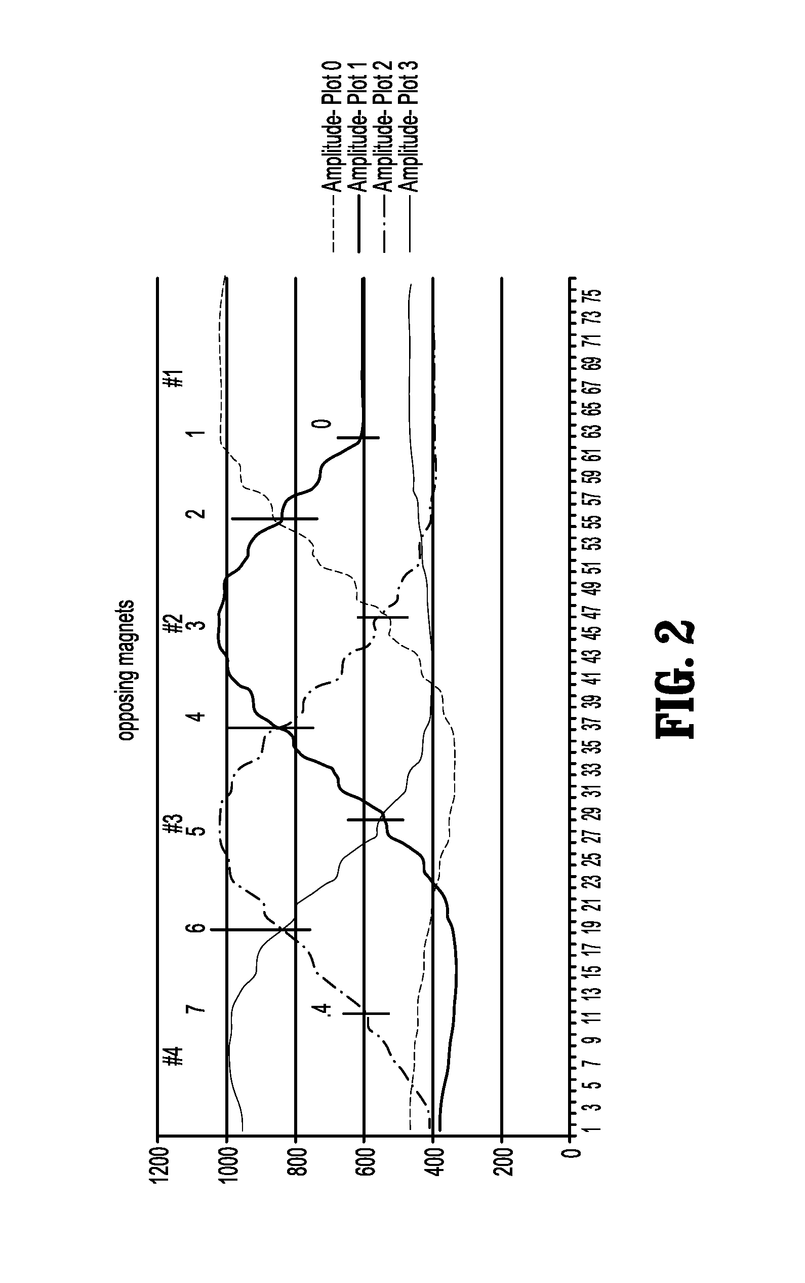
FIG. 2 is a graphic illustration of points of interest along response curves for linear distance measurements using a pair of magnets and four magnetic sensors;
FIG. 3 is a cross-sectional view, taken along section line 3-3 in FIG. 1, of components of an end effector of the surgical stapling instrument including a linear position assembly;
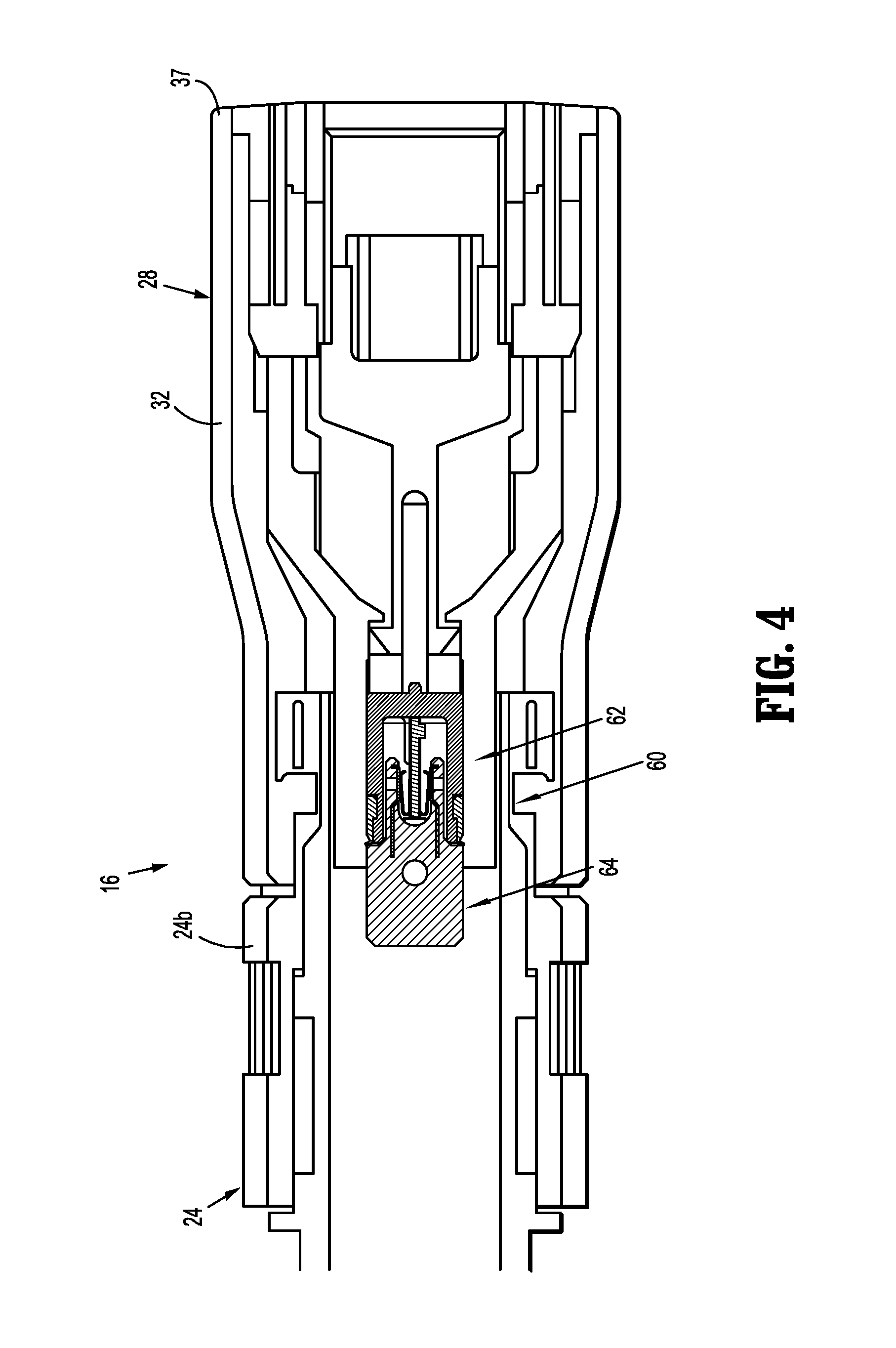
FIG. 4 is a cross-sectional view of a distal end of the surgical stapling instrument of FIG. 1 illustrating a chip assembly of the linear position assembly;
FIG. 5A is a perspective view of the chip assembly of FIG. 4; and
FIG. 5B is a perspective view, with parts separated, of the chip assembly of FIG. 4.
DETAILED DESCRIPTION
Persons having skill in the art will understand the present disclosure from reading the following description in conjunction with the accompanying drawings. Reference characters indicate the same or similar elements throughout the drawings. As is customary, the term "distal" refers to a location farther from the user of the instrument and the term "proximal" refers to a location that is closer to the user of the instrument.
FIG. 1 illustrates an embodiment of a surgical stapling instrument according to the present disclosure, referenced generally as a circular stapler 10. Circular stapler 10 includes a handle assembly 12, an adapter assembly 14, which is supported by and extends distally from handle assembly 12, and a surgical loading unit 15 coupled to a distal end 22 of adapter assembly 14. Adapter assembly 14 is reusable and includes a knob housing 18 that is releasably coupled to a distal end of handle assembly 12, and an elongated body portion 20 that extends distally from knob housing 18. Elongated body portion 20 has a distal end 22 that is configured to be coupled to an elongate body 24 of loading unit 15. Adapter assembly 14 converts a rotation of drive elements (not shown) of handle assembly 12 into axial movement of driven members (not shown) of adapter assembly 14 to actuate functions of loading unit 15. A similar adapter assembly is disclosed in U.S. Patent Application Publication No. 2013/0324978, which is incorporated herein in its entirety by reference.
In some embodiments, circular stapler 10 may have an elongated body portion that is integrally formed with a manually actuatable handle assembly instead of an adapter assembly. One example of such a stapler is disclosed in U.S. Pat. No. 7,802,712, which is incorporated herein in its entirety by reference.
Loading unit 15 includes an elongate body 24 and an end effector 26 supported on elongate body 24. Elongate body 24 has a proximal end 24a releasably coupled to distal end 22 of elongated body portion 20 of adapter assembly 14. In some embodiments, elongate body 24 may be monolithically formed with or integrally connected to distal end 22 of elongated body portion 20.
With reference to FIGS. 1 and 3, end effector 26 of loading unit 15 includes a cartridge assembly 28 and an anvil assembly 30. Cartridge assembly 28 is releasably mounted to a distal end 24b of elongate body 24 and defines a longitudinal axis "X." Cartridge assembly 28 includes a staple cartridge 32 configured for supporting a plurality of surgical staples (not shown) therein and to discharge the staples into tissue after approximation of cartridge assembly 28 and anvil assembly 30. Staple cartridge 32 defines a longitudinal channel 34 for movable receipt of an anvil shaft 36 of anvil assembly 30. Staple cartridge 32 has a plurality of staple retaining recesses 33 having the surgical staples disposed therein. Staple retaining recesses 33 are arranged in annular rows. It is envisioned that cartridge assembly 28 may be operably mounted to a distal end of any actuation assembly, powered or manual, of various surgical instruments.
Anvil assembly 30 includes, inter alia, an anvil shaft 36, an anvil head 38, and an anvil center rod 40 extending from anvil head 38. Anvil shaft 36 extends from elongate body 24 of loading unit 15 and is movably disposed within channel 34 of cartridge assembly 28 along longitudinal axis "X." A proximal end (not shown) of anvil shaft 36 is configured to be removably or non-removably coupled to a central shaft 16 of adapter assembly 14. As known in the art, central shaft 16 of adapter assembly 14 is operable to selectively longitudinally move anvil shaft 36 to move anvil head 38, which is supported on anvil shaft 36, between unapproximated and approximated positions, in relation to cartridge assembly 28, in response to actuation of handle assembly 12.
A proximal end 42 of anvil shaft 36 extends proximally from anvil head 38 and is configured for selective connection with a distal end of central shaft 16 of adapter assembly 14, to secure anvil assembly 30 to adapter assembly 14. As such, longitudinal movement of anvil shaft 36, via an actuation of handle assembly 12, results in a corresponding longitudinal movement of anvil head 38 relative to cartridge assembly 28 to clamp tissue between cartridge and anvil assemblies 28, 30. In some embodiments, anvil shaft 36 may be monolithically formed with central shaft 16. Reference may be made to U.S. Pat. No. 7,802,712 for a detailed description of the construction and operation of an end effector including a cartridge assembly and an anvil assembly similar to that disclosed herein.
With reference to FIG. 3, circular stapler 10 includes a linear position assembly 50 including a pair of magnets 52a, 52b and a plurality of sensors 54a, 54b, 54c. Magnets 52a, 52b are in the form of magnetic bars. In some embodiments, magnets 52a, 52b may be variously shaped, such as, for example, cylindrical, rounded, squared, oval, polygonal, uniform, or non-uniform. Magnets 52a, 52b generate a magnetic field that is detected by sensors 54a, 54b, 54c and used to ultimately determine a linear position "LP" of anvil assembly 30 relative to cartridge assembly 28, as will be described in detail below.
Magnets 52a, 52b are mounted to central shaft 16 of adapter assembly 14. In particular, magnets 52a, 52b are attached to an outer surface of central shaft 16 such that magnets 52a, 52b move with central shaft 16, along longitudinal axis "X," as central shaft 16 moves relative to cartridge assembly 28 between the unapproximated and approximated positions. In some embodiments, magnets 52a, 52b may be supported on or disposed in various components of anvil assembly 30, for example, various regions of anvil shaft 36, anvil head 38 and/or anvil rod 40.
Magnets 52a, 52b each have a north pole "N" and a south pole "S." Magnets 52a, 52b are oriented in a side-by-side orientation relative to one another such that magnets 52a, 52b have their respective opposing poles (i.e., north-north or south-south) adjacent one another. In this way, the magnetic field generated by each magnet 52a, 52b causes magnets 52a, 52b to repel one another. As illustrated in FIG. 2, magnets 52a, 52b, positioned with their magnetic fields opposing one another, results in a unique magnetic field being generated that is easier to formulate a linear distance therefrom as compared to using distinctive magnetic waveforms. In some embodiments, magnets 52a, 52b are positioned relative to one another with their attracting poles (i.e., north-south) adjacent one another, and four (4) sensors may be fixedly positioned within cartridge assembly 28 which function together to produce the plots shown in FIG. 2 as magnets 52a, 52b translate axially across a linear array of the four magnetic sensors.
A housing or casing 56 attached to central shaft 16 encloses magnets 52a, 52b to maintain magnets 52a, 52b positioned adjacent one another in their opposing configuration. Alternately, magnets 52a, 52b may be affixed to central shaft 16 or may be embedded into central shaft 16.
With continued reference to FIG. 3, circular stapler 10, and more specifically cartridge assembly 28, includes three sensors 54a, 54b, 54c that act in conjunction with magnets 52a, 52b and a microcontroller 58 to determine the gap or linear position "LP" between distal end 37 of staple cartridge 32 and anvil head 38 of anvil assembly 30. In some embodiments, more or less than three sensors may be provided. Sensors 54a-c are fixedly attached to a chip assembly 60, as will be described in greater detail below. In some embodiments, sensors 54a-c may be fixed to various portions of cartridge assembly 30. Sensors 54a-c are axially aligned with one another along longitudinal axis "X" such that sensors 54a-c are laterally offset and parallel with magnets 52a, 52b.
Sensors 54a-c are configured to sense a change in the magnetic field emitted by magnets 52a, 52b upon longitudinal movement of magnets 52a, 52b relative to sensors 54a-c as central shaft 16 is displaced or moved axially. Sensors 54a-c are in the form of magnetoresistance sensors. As such, magnetoresistance sensors 54a-c are configured to sense or determine an angle of direction of the magnetic field emitted by magnets 52a, 52b throughout relative longitudinal movement of magnets 52a, 52b. In some embodiments, sensors 54a-c may be in the form of hall-effect sensors. Hall-effect sensors are configured to sense or determine a magnetic flux density of the magnetic field emitted by magnets 52a, 52b throughout relative longitudinal movement of magnets 52a, 52b.
Circular stapler 10 may include a display unit and/or indicator (not shown) for displaying information, for example, the relative linear position of anvil shaft 36 and cartridge assembly 28. Additionally or alternatively, circular stapler 10 may include an audio component for sounding an audible alarm or recorded message. The display can be a light emitting diode, liquid crystal display, or any other display.
Circular stapler 10 includes a controller, such as, for example, a microcontroller 58. Microcontroller 58 is in electrical communication with each of sensors 54a-c. Microcontroller 58 is connected to sensors 54a-c by wires, leads, or via wireless connection. Sensors 54a-c relay, to microcontroller 58, the sensed angle of direction of the magnetic field of magnets 52a, 52b or the sensed magnetic flux density of the magnetic field of magnets 52a, 52b. Microcontroller 58 is configured to determine, based on the information relayed by sensors 54a-c, a linear position of anvil assembly 30 along longitudinal axis "X" relative to cartridge assembly 28, as will be described in greater detail below. Microcontroller 58 includes tables of information that indicate the desired gap or linear position "LP" for a particular loading unit (based on staple size, staple line length, etc.) and can be used to prevent the firing of staples in the event that the desired gap cannot be achieved. For example, U.S. Patent Publication No. 2012/0211542 discloses tissue management modes for controlling a surgical instrument and utilizes stored correlation tables, the entire contents of which being incorporated by reference herein.
Microcontroller 58 can be an integrated circuit, analog or logic circuitry, and/or microprocessor, or an array of such components. Microcontroller 58 receives information from a memory unit 70, other sensors in adapter assembly 14 and/or loading unit 15, and can control the operation of circular stapling instrument 10. Microcontroller 58 can initiate a visual or audible alarm in the event that a selected gap between anvil assembly 30 and cartridge assembly 28 is achieved, or microcontroller 58 can cease operation of circular stapler 10 by halting a motor (not shown) of handle assembly 12.
With reference to FIGS. 4, 5A and 5B, loading unit 15 further includes a chip assembly 60. Chip assembly 60 includes a housing assembly 62 and a plug assembly 64 configured to be releasably engaged to one another upon assembly of cartridge assembly 28 with distal end 24b of elongate body 24 of loading unit 15. Housing assembly 62 is configured to be securely mounted within cartridge assembly 28, and plug assembly 64 is configured to be securely mounted within distal end 24b of elongate body 24. Housing assembly 62 and plug assembly 64 are positioned within respective cartridge assembly 28 and elongate body 24 such that when cartridge assembly 28 is secured to distal end 24b of elongate body 24, housing assembly 62 engages plug assembly 64. It is envisioned that one or both of housing assembly 62 and plug assembly 64 may be spring biased towards the other to overcome any manufacturing tolerances between cartridge assembly 28 and elongate body 24.
Chip assembly 60 includes memory unit or chip 70 mentioned above. Chip 70 may be any suitable commercially available chip capable of storing the specifications of end effector 26 including, but not limited to, a distance between magnets 52a, 52b, a distance between each magnet 52a, 52b and anvil head 38, a distance between sensors 54a-c, and a distance between each sensor 54a-c and distal end 37 of staple cartridge 32, and transmitting the specifications to microprocessor 58. In one embodiment, chip 70 includes an erasable programmable read only memory ("EPROM") chip.
Upon housing assembly 62 being connected to plug assembly 64, within adapter assembly 14, it is envisioned that chip 70 will automatically transmit the specifications of end effector 26 to microprocessor 58 so that microprocessor 58 can determine the relative positions of anvil assembly 30 and cartridge assembly 28 during actuation of anvil assembly 30 using the stored information from memory unit 70 and the sensed information provided by sensors 54a-c, as will be described in detail below.
Referring to FIG. 3, in an operation of circular stapler 10, an unknown and changing linear position "LP" of anvil head 38 relative to distal end 37 of staple cartridge 32 is to be determined throughout an actuation of circular stapler 10. As circular stapler 10 is actuated, the central shaft 16 moves anvil shaft 36 proximally, in the direction indicated by arrow "A" in FIG. 3. Proximal longitudinal movement of anvil shaft 36 approximates anvil head 38 toward distal end 37 of staple cartridge 32 via the fixed engagement or connection between central shaft 16 of adapter assembly 14 and anvil shaft 36 of anvil assembly 30. Proximal longitudinal movement of central shaft 16 effects linear movement of magnets 52a, 52b relative to sensors 54a-c since magnets 52a, 52b are fixedly engaged to proximally moving central shaft 16.
The linear movement of magnets 52a, 52b relative to sensors 54a-c changes both the magnetic flux density of the magnetic field emitted by magnets 52a, 52b relative to sensors 54a-c and the angle of direction of the magnetic field emitted by magnets 52a, 52b relative to sensors 54a-c. As mentioned above, magnets 52a, 52b being positioned with their magnetic fields opposing one another results in a unique magnetic field being generated that permits formulation or calculation of a linear distance therefrom as compared to using distinctive magnetic waveforms.
In the embodiments wherein sensors 54a-c are magnetoresistance sensors, sensors 54a-c sense the change in the angle of direction of the magnetic field of magnets 52a, 52b. In the embodiments wherein sensors 54a-c are hall-effect sensors, sensors 54a-c sense the change in the magnetic flux density of the magnetic field of magnets 52a, 52b. In embodiments, sensors 54a-c may sense both the change in the angle of direction and the magnetic flux density of the magnets 52a, 52b.
Each sensor 54a-c converts the sensed magnetic field to a voltage output that corresponds to the linear position of magnets 52a, 52b relative to each sensor 54a-c. Sensors 54a-c relay the voltage output to microcontroller 58, which determines which sensor 54a, 54b, or 54c of sensors 54a-c has a highest peak-to-peak voltage value and which sensor 54a, 54b, or 54c of sensors 54a-c has a second highest peak-to-peak voltage value. Using this information, microcontroller 58 determines the linear distance (i.e., distance along longitudinal axis "X") between magnets 52a, 52b and sensors 54a-c by comparing the determined first and second highest peak-to-peak voltage values to known peak-to-peak voltage values for sensors of a similar type sensors 54a-c. The known peak-to-peak voltage values correspond to a known linear distance between two, adjacent magnets and three, adjacent sensors.
Once the linear position of magnets 52a, 52b relative to sensors 54a-c is determined, microcontroller 58 determines the linear position "LP" between anvil head 38 and distal end 37 of staple cartridge 32. Microcontroller 58 determines the linear position "LP" using the information received from sensors 54a-c pertaining to the linear position of magnets 52a, 52b relative to sensors 54a-c, and the information stored in chip 70 of chip assembly 60, which includes the distance between magnets 52a, 52b and anvil head 38, and the distance between sensors 54a-c and distal end 37 of staple cartridge 32, and the known sizes and dimensions of the components of cartridge assembly 28 and anvil assembly 30. The linear position "LP" is determined dynamically at various points in time throughout actuation of end effector 26. The determined linear positions "LP" are displayed on a screen (not shown) to be visually identified by a clinician who can use the information to gain insight about tissue thickness, when to fire staples into clamped tissue, etc.
In any of the embodiments disclosed herein, electronic sensors, optical sensors, magnetic sensors, and/or any other kind of sensors, can be used in addition to sensors 54a-c described herein to provide information about the particular loading unit and its use. In a stapling instrument of the type referenced herein, the sensors 54a-c and/or magnets 52a, 52b may be provided along any component or components which move during operation. For example, an electronic sensor, hall-effect sensor, magnetoresistance sensor, optic sensor, or other sensor, and/or magnets may be provided on any component of anvil assembly 30 or cartridge assembly 28, including chip assembly 60, anvil shaft 36, anvil head 38, channel 34, distal end 37 of staple cartridge 32, or any combination thereof.
In some embodiments, microcontroller 58 may include one or more microprocessors or chips. Microcontroller 58 may include more than one such chips or processors, and can be an array of such elements. Data for determining the type and characteristics of end effectors, adapter assemblies and/or handle portions can be stored in memory units in the form of graphs, charts, tables, arrays, or the like. This can be used in conjunction with other systems provided for circular stapler 10.
While the present disclosure has been described and illustrated in connection with certain embodiments, it is not the intention of the applicant to restrict or in any other way limit the scope of the claims to such detail. Additional advantages and modifications will be readily apparent to those skilled in the art.
* * * * *
D00000
D00001
D00002
D00003
D00004
D00005
XML
uspto.report is an independent third-party trademark research tool that is not affiliated, endorsed, or sponsored by the United States Patent and Trademark Office (USPTO) or any other governmental organization. The information provided by uspto.report is based on publicly available data at the time of writing and is intended for informational purposes only.
While we strive to provide accurate and up-to-date information, we do not guarantee the accuracy, completeness, reliability, or suitability of the information displayed on this site. The use of this site is at your own risk. Any reliance you place on such information is therefore strictly at your own risk.
All official trademark data, including owner information, should be verified by visiting the official USPTO website at www.uspto.gov. This site is not intended to replace professional legal advice and should not be used as a substitute for consulting with a legal professional who is knowledgeable about trademark law.