Boost converter and controller for increasing voltage received from wireless power transmission waves
Leabman Ja
U.S. patent number 10,186,911 [Application Number 15/799,933] was granted by the patent office on 2019-01-22 for boost converter and controller for increasing voltage received from wireless power transmission waves. This patent grant is currently assigned to Energous Corporation. The grantee listed for this patent is ENERGOUS CORPORATION. Invention is credited to Michael A. Leabman.


| United States Patent | 10,186,911 |
| Leabman | January 22, 2019 |
| **Please see images for: ( Certificate of Correction ) ** |
Boost converter and controller for increasing voltage received from wireless power transmission waves
Abstract
An exemplary method of receiving wireless power from a wireless power transmitter includes, at a wireless power receiver having a controller, an antenna, a rectifier coupled with the antenna, and a boost converter coupled with the rectifier: (i) rectifying, by the rectifier, energy from wireless power transmission waves received by the antenna into a first voltage, (ii) increasing, by the boost converter, the first voltage to a second voltage based on instructions from the controller, and (iii) controlling, by the controller, an amount of increase in voltage from the first voltage to the second voltage based on a comparison.
| Inventors: | Leabman; Michael A. (Pleasanton, CA) | ||||||||||
|---|---|---|---|---|---|---|---|---|---|---|---|
| Applicant: |
|
||||||||||
| Assignee: | Energous Corporation (San Jose,
CA) |
||||||||||
| Family ID: | 54368683 | ||||||||||
| Appl. No.: | 15/799,933 | ||||||||||
| Filed: | October 31, 2017 |
Prior Publication Data
| Document Identifier | Publication Date | |
|---|---|---|
| US 20180131238 A1 | May 10, 2018 | |
Related U.S. Patent Documents
| Application Number | Filing Date | Patent Number | Issue Date | ||
|---|---|---|---|---|---|
| 14272287 | May 7, 2014 | 9806564 | |||
| Current U.S. Class: | 1/1 |
| Current CPC Class: | H02M 3/156 (20130101); H02M 7/217 (20130101); H02J 50/80 (20160201); H02M 7/06 (20130101); H02M 7/066 (20130101); H02J 50/20 (20160201); H02J 7/025 (20130101); H02M 3/1588 (20130101); G05F 1/67 (20130101); Y02B 70/10 (20130101); H02M 2001/0022 (20130101); H02M 2001/007 (20130101); Y02B 70/1466 (20130101) |
| Current International Class: | H02J 50/20 (20160101); H02J 50/80 (20160101); H02J 7/02 (20160101); H02M 3/156 (20060101); H02M 7/06 (20060101); H02M 7/217 (20060101); G05F 1/67 (20060101); H02M 3/158 (20060101); H02M 1/00 (20060101) |
References Cited [Referenced By]
U.S. Patent Documents
| 787412 | April 1905 | Tesla |
| 3434678 | March 1969 | Brown et al. |
| 3696384 | October 1972 | Lester |
| 3754269 | August 1973 | Clavin |
| 4101895 | July 1978 | Jones, Jr. |
| 4360741 | November 1982 | Fitzsimmons et al. |
| 4944036 | July 1990 | Hyatt |
| 4995010 | February 1991 | Knight |
| 5200759 | April 1993 | McGinnis |
| 5211471 | May 1993 | Rohrs |
| 5548292 | August 1996 | Hirshfield et al. |
| 5556749 | September 1996 | Mitsuhashi et al. |
| 5568088 | October 1996 | Dent et al. |
| 5646633 | July 1997 | Dahlberg |
| 5697063 | December 1997 | Kishigami et al. |
| 5712642 | January 1998 | Hulderman |
| 5936527 | August 1999 | Isaacman et al. |
| 5982139 | November 1999 | Parise |
| 6046708 | April 2000 | MacDonald, Jr. et al. |
| 6127799 | October 2000 | Krishnan |
| 6127942 | October 2000 | Welle |
| 6163296 | December 2000 | Lier et al. |
| 6289237 | September 2001 | Mickle et al. |
| 6329908 | December 2001 | Frecska |
| 6421235 | July 2002 | Ditzik |
| 6437685 | August 2002 | Hanaki |
| 6456253 | September 2002 | Rummeli et al. |
| 6476795 | November 2002 | Derocher et al. |
| 6501414 | December 2002 | Amdt et al. |
| 6583723 | June 2003 | Watanabe et al. |
| 6597897 | July 2003 | Tang |
| 6615074 | September 2003 | Mickle et al. |
| 6664920 | December 2003 | Mott et al. |
| 6798716 | September 2004 | Charych |
| 6803744 | October 2004 | Sabo |
| 6853197 | February 2005 | McFarland |
| 6856291 | February 2005 | Mickle et al. |
| 6911945 | June 2005 | Korva |
| 6960968 | November 2005 | Odendaal et al. |
| 6967462 | November 2005 | Landis |
| 6988026 | January 2006 | Breed et al. |
| 7003350 | February 2006 | Denker et al. |
| 7027311 | April 2006 | Vanderelli et al. |
| 7068234 | June 2006 | Sievenpiper |
| 7068991 | June 2006 | Parise |
| 7183748 | February 2007 | Unno et al. |
| 7191013 | March 2007 | Miranda et al. |
| 7196663 | March 2007 | Bolzer et al. |
| 7205749 | April 2007 | Hagen et al. |
| 7222356 | May 2007 | Yonezawa et al. |
| 7274334 | September 2007 | o'Riordan et al. |
| 7274336 | September 2007 | Carson |
| 7351975 | April 2008 | Brady et al. |
| 7359730 | April 2008 | Dennis et al. |
| 7392068 | June 2008 | Dayan |
| 7403803 | July 2008 | Mickle et al. |
| 7451839 | November 2008 | Perlman |
| 7463201 | December 2008 | Chiang et al. |
| 7471247 | December 2008 | Saily |
| 7535195 | May 2009 | Horovitz et al. |
| 7614556 | November 2009 | Overhultz et al. |
| 7639994 | December 2009 | Greene et al. |
| 7643312 | January 2010 | Vanderelli et al. |
| 7652577 | January 2010 | Madhow et al. |
| 7702771 | April 2010 | Ewing et al. |
| 7786419 | August 2010 | Hyde et al. |
| 7812771 | October 2010 | Greene et al. |
| 7830312 | November 2010 | Choudhury et al. |
| 7844306 | November 2010 | Shearer et al. |
| 7868482 | January 2011 | Greene et al. |
| 7898105 | March 2011 | Greene et al. |
| 7904117 | March 2011 | Doan et al. |
| 7911386 | March 2011 | Ito et al. |
| 7925308 | April 2011 | Greene et al. |
| 8055003 | November 2011 | Mittleman et al. |
| 8070595 | December 2011 | Alderucci et al. |
| 8072380 | December 2011 | Crouch |
| 8092301 | January 2012 | Alderucci et al. |
| 8099140 | January 2012 | Arai |
| 8115448 | February 2012 | John |
| 8159090 | April 2012 | Greene et al. |
| 8159364 | April 2012 | Zeine |
| 8180286 | May 2012 | Yamasuge |
| 8228194 | July 2012 | Mickle |
| 8264101 | September 2012 | Hyde et al. |
| 8264291 | September 2012 | Morita |
| 8276325 | October 2012 | Clifton et al. |
| 8278784 | October 2012 | Cook et al. |
| 8284101 | October 2012 | Fusco |
| 8310201 | November 2012 | Wright |
| 8362745 | January 2013 | Tinaphong |
| 8380255 | February 2013 | Shearer et al. |
| 8410953 | April 2013 | Zeine |
| 8411963 | April 2013 | Luff |
| 8432062 | April 2013 | Greene et al. |
| 8432071 | April 2013 | Huang et al. |
| 8446248 | May 2013 | Zeine |
| 8447234 | May 2013 | Cook et al. |
| 8451189 | May 2013 | Fluhler |
| 8452235 | May 2013 | Kirby et al. |
| 8457656 | June 2013 | Perkins et al. |
| 8461817 | June 2013 | Martin et al. |
| 8467733 | June 2013 | Leabman |
| 8497658 | July 2013 | Von Novak et al. |
| 8552597 | August 2013 | Song et al. |
| 8558661 | October 2013 | Zeine |
| 8560026 | October 2013 | Chanterac |
| 8604746 | December 2013 | Lee |
| 8614643 | December 2013 | Leabman |
| 8621245 | December 2013 | Shearer et al. |
| 8626249 | January 2014 | Kuusilinna et al. |
| 8629576 | January 2014 | Levine |
| 8653966 | February 2014 | Rao et al. |
| 8674551 | March 2014 | Low et al. |
| 8686685 | April 2014 | Moshfeghi |
| 8712355 | April 2014 | Black et al. |
| 8712485 | April 2014 | Tam |
| 8718773 | May 2014 | Wills et al. |
| 8729737 | May 2014 | Schatz et al. |
| 8736228 | May 2014 | Freed et al. |
| 8760113 | June 2014 | Keating |
| 8770482 | July 2014 | Ackermann et al. |
| 8772960 | July 2014 | Yoshida |
| 8823319 | September 2014 | Von Novak, III et al. |
| 8854176 | October 2014 | Zeine |
| 8860364 | October 2014 | Low et al. |
| 8897770 | November 2014 | Frolov et al. |
| 8923189 | December 2014 | Leabman |
| 8928544 | January 2015 | Massie et al. |
| 8937408 | January 2015 | Ganem et al. |
| 8946940 | February 2015 | Kim et al. |
| 8963486 | February 2015 | Kirby et al. |
| 8970070 | March 2015 | Sada et al. |
| 8989053 | March 2015 | Skaaksrud et al. |
| 9000616 | April 2015 | Greene et al. |
| 9001622 | April 2015 | Perry |
| 9006934 | April 2015 | Kozakai et al. |
| 9021277 | April 2015 | Shearer et al. |
| 9030161 | May 2015 | Lu et al. |
| 9059598 | June 2015 | Kang et al. |
| 9059599 | June 2015 | Won et al. |
| 9077188 | July 2015 | Moshfeghi |
| 9088216 | July 2015 | Garrity et al. |
| 9124125 | September 2015 | Leabman et al. |
| 9130397 | September 2015 | Leabman et al. |
| 9130602 | September 2015 | Cook |
| 9142998 | September 2015 | Yu et al. |
| 9143000 | September 2015 | Leabman et al. |
| 9143010 | September 2015 | Urano |
| 9178389 | November 2015 | Hwang |
| 9225196 | December 2015 | Huang et al. |
| 9242411 | January 2016 | Kritchman et al. |
| 9244500 | January 2016 | Cain et al. |
| 9252628 | February 2016 | Leabman et al. |
| 9270344 | February 2016 | Rosenberg |
| 9282582 | March 2016 | Dunsbergen et al. |
| 9294840 | March 2016 | Anderson et al. |
| 9297896 | March 2016 | Andrews |
| 9318898 | April 2016 | John |
| 9368020 | June 2016 | Bell et al. |
| 9401977 | July 2016 | Gaw |
| 9438045 | September 2016 | Leabman |
| 9438046 | September 2016 | Leabman |
| 9444283 | September 2016 | Son et al. |
| 9450449 | September 2016 | Leabman et al. |
| 9461502 | October 2016 | Lee et al. |
| 9520725 | December 2016 | Masaoka et al. |
| 9520748 | December 2016 | Hyde et al. |
| 9522270 | December 2016 | Perryman et al. |
| 9537354 | January 2017 | Bell et al. |
| 9537357 | January 2017 | Leabman |
| 9537358 | January 2017 | Leabman |
| 9538382 | January 2017 | Bell et al. |
| 9544640 | January 2017 | Lau |
| 9559553 | January 2017 | Bae |
| 9564773 | February 2017 | Pogorelik et al. |
| 9571974 | February 2017 | Choi et al. |
| 9590444 | March 2017 | Walley |
| 9620996 | April 2017 | Zeine |
| 9706137 | July 2017 | Scanlon et al. |
| 9800172 | October 2017 | Leabman |
| 9853361 | December 2017 | Chen et al. |
| 9876394 | January 2018 | Leabman |
| 2002/0001307 | January 2002 | Nguyen et al. |
| 2002/0028655 | March 2002 | Rosener et al. |
| 2002/0034958 | March 2002 | Oberschmidt et al. |
| 2002/0054330 | May 2002 | Jinbo et al. |
| 2002/0065052 | May 2002 | Pande et al. |
| 2002/0072784 | June 2002 | Sheppard et al. |
| 2002/0095980 | July 2002 | Breed et al. |
| 2002/0103447 | August 2002 | Terry |
| 2002/0133592 | September 2002 | Matsuda |
| 2002/0172223 | November 2002 | Stilp |
| 2003/0005759 | January 2003 | Breed et al. |
| 2003/0058187 | March 2003 | Billiet et al. |
| 2003/0076274 | April 2003 | Phelan et al. |
| 2003/0179152 | September 2003 | Watada et al. |
| 2003/0179573 | September 2003 | Chun |
| 2003/0192053 | October 2003 | Sheppard et al. |
| 2004/0019624 | January 2004 | Sukegawa |
| 2004/0020100 | February 2004 | O' Brian et al. |
| 2004/0036657 | February 2004 | Forster et al. |
| 2004/0066251 | April 2004 | Eleftheriades et al. |
| 2004/0107641 | June 2004 | Walton et al. |
| 2004/0113543 | June 2004 | Daniels |
| 2004/0119675 | June 2004 | Washio et al. |
| 2004/0130425 | July 2004 | Dayan et al. |
| 2004/0130442 | July 2004 | Breed |
| 2004/0142733 | July 2004 | Parise |
| 2004/0145342 | July 2004 | Lyon |
| 2004/0196190 | October 2004 | Mendolia et al. |
| 2004/0207559 | October 2004 | Milosavljevic |
| 2004/0218759 | November 2004 | Yacobi |
| 2004/0259604 | December 2004 | Mickle et al. |
| 2004/0263124 | December 2004 | Wieck et al. |
| 2005/0007276 | January 2005 | Barrick et al. |
| 2005/0030118 | February 2005 | Wang |
| 2005/0046584 | March 2005 | Breed |
| 2005/0055316 | March 2005 | Williams |
| 2005/0077872 | April 2005 | Single |
| 2005/0093766 | May 2005 | Turner |
| 2005/0116683 | June 2005 | Cheng |
| 2005/0117660 | June 2005 | Vialle et al. |
| 2005/0171411 | August 2005 | KenKnight |
| 2005/0198673 | September 2005 | Kit et al. |
| 2005/0227619 | October 2005 | Lee et al. |
| 2005/0232469 | October 2005 | Schofield |
| 2005/0282591 | December 2005 | Shaff |
| 2006/0013335 | January 2006 | Leabman |
| 2006/0019712 | January 2006 | Choi |
| 2006/0030279 | February 2006 | Leabman et al. |
| 2006/0092079 | May 2006 | de Rochemont |
| 2006/0094425 | May 2006 | Mickle et al. |
| 2006/0113955 | June 2006 | Nunally |
| 2006/0119532 | June 2006 | Yun et al. |
| 2006/0136004 | June 2006 | Cowan et al. |
| 2006/0160517 | July 2006 | Yoon |
| 2006/0183473 | August 2006 | Ukon |
| 2006/0190063 | August 2006 | Kanzius |
| 2006/0192913 | August 2006 | Shutou et al. |
| 2006/0199620 | September 2006 | Greene et al. |
| 2006/0238365 | October 2006 | Vecchione et al. |
| 2006/0266564 | November 2006 | Perlman et al. |
| 2006/0266917 | November 2006 | Baldis et al. |
| 2006/0278706 | December 2006 | Hatakayama et al. |
| 2006/0284593 | December 2006 | Nagy et al. |
| 2006/0287094 | December 2006 | Mahaffey et al. |
| 2007/0007821 | January 2007 | Rossetti |
| 2007/0019693 | January 2007 | Graham |
| 2007/0021140 | January 2007 | Keyes |
| 2007/0060185 | March 2007 | Simon et al. |
| 2007/0070490 | March 2007 | Tsunoda et al. |
| 2007/0093269 | April 2007 | Leabman et al. |
| 2007/0097653 | May 2007 | Gilliland et al. |
| 2007/0103110 | May 2007 | Sagoo |
| 2007/0106894 | May 2007 | Zhang |
| 2007/0109121 | May 2007 | Cohen |
| 2007/0139000 | June 2007 | Kozuma |
| 2007/0149162 | June 2007 | Greene et al. |
| 2007/0173196 | July 2007 | Gallic |
| 2007/0173214 | July 2007 | Mickle et al. |
| 2007/0178857 | August 2007 | Greene et al. |
| 2007/0178945 | August 2007 | Cook et al. |
| 2007/0182367 | August 2007 | Partovi |
| 2007/0191074 | August 2007 | Harrist et al. |
| 2007/0191075 | August 2007 | Greene et al. |
| 2007/0197281 | August 2007 | Stronach |
| 2007/0210960 | September 2007 | Rofougaran et al. |
| 2007/0222681 | September 2007 | Greene et al. |
| 2007/0257634 | November 2007 | Leschin et al. |
| 2007/0273486 | November 2007 | Shiotsu |
| 2007/0298846 | December 2007 | Greene et al. |
| 2008/0014897 | January 2008 | Cook et al. |
| 2008/0048917 | February 2008 | Achour et al. |
| 2008/0062062 | March 2008 | Borau et al. |
| 2008/0062255 | March 2008 | Gal |
| 2008/0067874 | March 2008 | Tseng |
| 2008/0074324 | March 2008 | Puzella et al. |
| 2008/0089277 | April 2008 | Aledander et al. |
| 2008/0113816 | May 2008 | Mahaffey et al. |
| 2008/0122297 | May 2008 | Arai |
| 2008/0123383 | May 2008 | Shionoiri |
| 2008/0129536 | June 2008 | Randall et al. |
| 2008/0169910 | July 2008 | Greene et al. |
| 2008/0197802 | August 2008 | Onishi |
| 2008/0204342 | August 2008 | Kharadly |
| 2008/0204350 | August 2008 | Tam et al. |
| 2008/0210762 | September 2008 | Osada et al. |
| 2008/0211458 | September 2008 | Lawther et al. |
| 2008/0248758 | October 2008 | Schedelbeck et al. |
| 2008/0248846 | October 2008 | Stronach et al. |
| 2008/0278378 | November 2008 | Chang et al. |
| 2008/0309452 | December 2008 | Zeine |
| 2009/0002493 | January 2009 | Kates |
| 2009/0019183 | January 2009 | Wu et al. |
| 2009/0036065 | February 2009 | Siu |
| 2009/0047998 | February 2009 | Alberth, Jr. |
| 2009/0058354 | March 2009 | Harrison |
| 2009/0058361 | March 2009 | John |
| 2009/0067208 | March 2009 | Martin et al. |
| 2009/0096412 | April 2009 | Huang |
| 2009/0096413 | April 2009 | Partovi |
| 2009/0102292 | April 2009 | Cook et al. |
| 2009/0102296 | April 2009 | Greene et al. |
| 2009/0108679 | April 2009 | Porwal |
| 2009/0122847 | May 2009 | Nysen et al. |
| 2009/0128262 | May 2009 | Lee et al. |
| 2009/0157911 | June 2009 | Aihara |
| 2009/0200985 | August 2009 | Zane et al. |
| 2009/0206791 | August 2009 | Jung |
| 2009/0207092 | August 2009 | Nysen et al. |
| 2009/0218884 | September 2009 | Soar |
| 2009/0218891 | September 2009 | McCollough |
| 2009/0219903 | September 2009 | Alamouti et al. |
| 2009/0243397 | October 2009 | Cook et al. |
| 2009/0264069 | October 2009 | Yamasuge |
| 2009/0280866 | November 2009 | Lo et al. |
| 2009/0281678 | November 2009 | Wakamatsu |
| 2009/0284082 | November 2009 | Mohammadian |
| 2009/0284083 | November 2009 | Karalis et al. |
| 2009/0284220 | November 2009 | Toncich et al. |
| 2009/0284227 | November 2009 | Mohammadian et al. |
| 2009/0284325 | November 2009 | Rossiter et al. |
| 2009/0286475 | November 2009 | Toncich et al. |
| 2009/0291634 | November 2009 | Saarisalo |
| 2009/0299175 | December 2009 | Bernstein et al. |
| 2009/0308936 | December 2009 | Nitzan et al. |
| 2009/0312046 | December 2009 | Clevenger et al. |
| 2009/0315412 | December 2009 | Yamamoto et al. |
| 2009/0322281 | December 2009 | Kamijo et al. |
| 2010/0001683 | January 2010 | Huang et al. |
| 2010/0007307 | January 2010 | Baarman et al. |
| 2010/0007569 | January 2010 | Sim et al. |
| 2010/0019686 | January 2010 | Gutierrez, Jr. |
| 2010/0026605 | February 2010 | Yang et al. |
| 2010/0027379 | February 2010 | Saulnier et al. |
| 2010/0029383 | February 2010 | Dai |
| 2010/0033021 | February 2010 | Bennett |
| 2010/0033390 | February 2010 | Alamouti et al. |
| 2010/0034238 | February 2010 | Bennett |
| 2010/0041453 | February 2010 | Grimm, Jr. |
| 2010/0044123 | February 2010 | Perlman et al. |
| 2010/0054200 | March 2010 | Tsai |
| 2010/0060534 | March 2010 | Oodachi |
| 2010/0075607 | March 2010 | Hosoya |
| 2010/0079005 | April 2010 | Hyde et al. |
| 2010/0082193 | April 2010 | Chiappetta |
| 2010/0087227 | April 2010 | Francos et al. |
| 2010/0090524 | April 2010 | Obayashi |
| 2010/0090656 | April 2010 | Shearer et al. |
| 2010/0109443 | May 2010 | Cook et al. |
| 2010/0119234 | May 2010 | Suematsu et al. |
| 2010/0123618 | May 2010 | Martin et al. |
| 2010/0123624 | May 2010 | Minear et al. |
| 2010/0127660 | May 2010 | Cook et al. |
| 2010/0142418 | June 2010 | Nishioka et al. |
| 2010/0142509 | June 2010 | Zhu et al. |
| 2010/0151808 | June 2010 | Toncich et al. |
| 2010/0156721 | June 2010 | Alamouti et al. |
| 2010/0164433 | July 2010 | Janefalker et al. |
| 2010/0171461 | July 2010 | Baarman et al. |
| 2010/0174629 | July 2010 | Taylor et al. |
| 2010/0176934 | July 2010 | Chou et al. |
| 2010/0181961 | July 2010 | Novak et al. |
| 2010/0181964 | July 2010 | Huggins et al. |
| 2010/0194206 | August 2010 | Burdo et al. |
| 2010/0201189 | August 2010 | Kirby et al. |
| 2010/0201201 | August 2010 | Mobarhan et al. |
| 2010/0201314 | August 2010 | Toncich et al. |
| 2010/0207572 | August 2010 | Kirby et al. |
| 2010/0210233 | August 2010 | Cook et al. |
| 2010/0214177 | August 2010 | Parsche |
| 2010/0222010 | September 2010 | Ozaki et al. |
| 2010/0225270 | September 2010 | Jacobs et al. |
| 2010/0227570 | September 2010 | Hendin |
| 2010/0231470 | September 2010 | Lee et al. |
| 2010/0237709 | September 2010 | Hall et al. |
| 2010/0244576 | September 2010 | Hillan et al. |
| 2010/0256831 | October 2010 | Abramo et al. |
| 2010/0259110 | October 2010 | Kurs et al. |
| 2010/0259447 | October 2010 | Crouch |
| 2010/0264747 | October 2010 | Hall et al. |
| 2010/0277003 | November 2010 | Von Novak et al. |
| 2010/0277121 | November 2010 | Hall et al. |
| 2010/0279606 | November 2010 | Hillan et al. |
| 2010/0289341 | November 2010 | Ozaki et al. |
| 2010/0295372 | November 2010 | Hyde et al. |
| 2010/0308767 | December 2010 | Rofougaran et al. |
| 2010/0309079 | December 2010 | Rofougaran et al. |
| 2010/0309088 | December 2010 | Hyvonen et al. |
| 2010/0315045 | December 2010 | Zeine |
| 2010/0316163 | December 2010 | Forenza et al. |
| 2010/0327766 | December 2010 | Recker et al. |
| 2010/0328044 | December 2010 | Waffenschmidt et al. |
| 2010/0332401 | December 2010 | Prahlad et al. |
| 2011/0018360 | January 2011 | Baarman et al. |
| 2011/0028114 | February 2011 | Kerselaers |
| 2011/0031928 | February 2011 | Soar |
| 2011/0032149 | February 2011 | Leabman |
| 2011/0032866 | February 2011 | Leabman |
| 2011/0034190 | February 2011 | Leabman |
| 2011/0034191 | February 2011 | Leabman |
| 2011/0043047 | February 2011 | Karalis et al. |
| 2011/0043163 | February 2011 | Baarman et al. |
| 2011/0043327 | February 2011 | Baarman et al. |
| 2011/0050166 | March 2011 | Cook et al. |
| 2011/0055037 | March 2011 | Hayashigawa et al. |
| 2011/0056215 | March 2011 | Ham |
| 2011/0057607 | March 2011 | Carobolante |
| 2011/0062788 | March 2011 | Chen et al. |
| 2011/0074342 | March 2011 | MacLaughlin |
| 2011/0074349 | March 2011 | Ghovanloo |
| 2011/0074620 | March 2011 | Wintermantel |
| 2011/0078092 | March 2011 | Kim et al. |
| 2011/0090126 | April 2011 | Szini et al. |
| 2011/0114401 | May 2011 | Kanno et al. |
| 2011/0115303 | May 2011 | Baarman et al. |
| 2011/0115432 | May 2011 | El-Maleh |
| 2011/0115605 | May 2011 | Dimig et al. |
| 2011/0121660 | May 2011 | Azancot et al. |
| 2011/0122026 | May 2011 | DeLaquil et al. |
| 2011/0127845 | June 2011 | Walley et al. |
| 2011/0127952 | June 2011 | Walley et al. |
| 2011/0133655 | June 2011 | Recker et al. |
| 2011/0133691 | June 2011 | Hautanen |
| 2011/0148578 | June 2011 | Aloi et al. |
| 2011/0151789 | June 2011 | Viglione et al. |
| 2011/0154429 | June 2011 | Stantchev |
| 2011/0156494 | June 2011 | Mashinsky |
| 2011/0156640 | June 2011 | Moshfeghi |
| 2011/0163128 | July 2011 | Taguchi et al. |
| 2011/0175455 | July 2011 | Hashiguchi |
| 2011/0175461 | July 2011 | Tinaphong |
| 2011/0181120 | July 2011 | Liu et al. |
| 2011/0182245 | July 2011 | Malkamaki et al. |
| 2011/0184842 | July 2011 | Melen |
| 2011/0188207 | August 2011 | Won et al. |
| 2011/0194543 | August 2011 | Zhao et al. |
| 2011/0195722 | August 2011 | Walter et al. |
| 2011/0199046 | August 2011 | Tsai et al. |
| 2011/0215086 | September 2011 | Yeh |
| 2011/0217923 | September 2011 | Ma |
| 2011/0220634 | September 2011 | Yeh |
| 2011/0221389 | September 2011 | Won et al. |
| 2011/0222272 | September 2011 | Yeh |
| 2011/0243040 | October 2011 | Khan et al. |
| 2011/0243050 | October 2011 | Yanover |
| 2011/0244913 | October 2011 | Kim et al. |
| 2011/0248573 | October 2011 | Kanno et al. |
| 2011/0248575 | October 2011 | Kim et al. |
| 2011/0249678 | October 2011 | Bonicatto |
| 2011/0254377 | October 2011 | Widmer et al. |
| 2011/0254503 | October 2011 | Widmer et al. |
| 2011/0259953 | October 2011 | Baarman et al. |
| 2011/0273977 | November 2011 | Shapira et al. |
| 2011/0278941 | November 2011 | Krishna et al. |
| 2011/0279226 | November 2011 | Chen et al. |
| 2011/0281535 | November 2011 | Low et al. |
| 2011/0282415 | November 2011 | Eckhoff et al. |
| 2011/0285213 | November 2011 | Kowalewski |
| 2011/0286374 | November 2011 | Shin et al. |
| 2011/0291489 | December 2011 | Tsai et al. |
| 2011/0302078 | December 2011 | Failing |
| 2011/0304216 | December 2011 | Baarman |
| 2011/0304437 | December 2011 | Beeler |
| 2012/0013196 | January 2012 | Kim et al. |
| 2012/0013198 | January 2012 | Uramoto et al. |
| 2012/0013296 | January 2012 | Heydari et al. |
| 2012/0019419 | January 2012 | Prat et al. |
| 2012/0043887 | February 2012 | Mesibov |
| 2012/0051109 | March 2012 | Kim et al. |
| 2012/0051294 | March 2012 | Guillouard |
| 2012/0056486 | March 2012 | Endo et al. |
| 2012/0056741 | March 2012 | Zhu et al. |
| 2012/0074891 | March 2012 | Anderson et al. |
| 2012/0080957 | April 2012 | Cooper et al. |
| 2012/0086284 | April 2012 | Capanella et al. |
| 2012/0095617 | April 2012 | Martin et al. |
| 2012/0098350 | April 2012 | Campanella et al. |
| 2012/0098485 | April 2012 | Kang et al. |
| 2012/0099675 | April 2012 | Kitamura et al. |
| 2012/0103562 | May 2012 | Clayton |
| 2012/0104849 | May 2012 | Jackson |
| 2012/0105252 | May 2012 | Wang |
| 2012/0112532 | May 2012 | Kesler et al. |
| 2012/0119914 | May 2012 | Uchida |
| 2012/0126743 | May 2012 | Rivers, Jr. |
| 2012/0132647 | May 2012 | Beverly et al. |
| 2012/0133214 | May 2012 | Yun et al. |
| 2012/0146426 | June 2012 | Sabo |
| 2012/0146576 | June 2012 | Partovi |
| 2012/0146577 | June 2012 | Tanabe |
| 2012/0147802 | June 2012 | Ukita et al. |
| 2012/0149307 | June 2012 | Terada et al. |
| 2012/0150670 | June 2012 | Taylor et al. |
| 2012/0153894 | June 2012 | Widmer et al. |
| 2012/0157019 | June 2012 | Li |
| 2012/0161531 | June 2012 | Kim et al. |
| 2012/0161544 | June 2012 | Kashiwagi et al. |
| 2012/0169276 | July 2012 | Wang |
| 2012/0169278 | July 2012 | Choi |
| 2012/0173418 | July 2012 | Beardsmore et al. |
| 2012/0179004 | July 2012 | Roesicke et al. |
| 2012/0181973 | July 2012 | Lyden |
| 2012/0182427 | July 2012 | Marshall |
| 2012/0187851 | August 2012 | Huggins et al. |
| 2012/0193999 | August 2012 | Zeine |
| 2012/0200399 | August 2012 | Chae |
| 2012/0201153 | August 2012 | Bharadia et al. |
| 2012/0201173 | August 2012 | Jian et al. |
| 2012/0206299 | August 2012 | Valdes-Garcia |
| 2012/0211214 | August 2012 | Phan |
| 2012/0212072 | August 2012 | Miyabayashi et al. |
| 2012/0214536 | August 2012 | Kim et al. |
| 2012/0228392 | September 2012 | Cameron et al. |
| 2012/0228956 | September 2012 | Kamata |
| 2012/0231856 | September 2012 | Lee et al. |
| 2012/0235636 | September 2012 | Partovi |
| 2012/0242283 | September 2012 | Kim et al. |
| 2012/0248886 | October 2012 | Kesler et al. |
| 2012/0248888 | October 2012 | Kesler et al. |
| 2012/0248891 | October 2012 | Drennen |
| 2012/0249051 | October 2012 | Son et al. |
| 2012/0262002 | October 2012 | Widmer et al. |
| 2012/0265272 | October 2012 | Judkins |
| 2012/0267900 | October 2012 | Huffman et al. |
| 2012/0268238 | October 2012 | Park et al. |
| 2012/0274154 | November 2012 | DeLuca |
| 2012/0280650 | November 2012 | Kim et al. |
| 2012/0286582 | November 2012 | Kim et al. |
| 2012/0292993 | November 2012 | Mettler et al. |
| 2012/0293021 | November 2012 | Teggatz et al. |
| 2012/0293119 | November 2012 | Park et al. |
| 2012/0299389 | November 2012 | Lee et al. |
| 2012/0299540 | November 2012 | Perry |
| 2012/0299541 | November 2012 | Perry |
| 2012/0299542 | November 2012 | Perry |
| 2012/0300588 | November 2012 | Perry |
| 2012/0300592 | November 2012 | Perry |
| 2012/0300593 | November 2012 | Perry |
| 2012/0306705 | December 2012 | Sakurai et al. |
| 2012/0309295 | December 2012 | Maguire |
| 2012/0309308 | December 2012 | Kim et al. |
| 2012/0309332 | December 2012 | Liao |
| 2012/0313449 | December 2012 | Kurs |
| 2012/0326660 | December 2012 | Lu et al. |
| 2013/0002550 | January 2013 | Zalewski |
| 2013/0024059 | January 2013 | Miller et al. |
| 2013/0026981 | January 2013 | Van Der Lee |
| 2013/0026982 | January 2013 | Rothenbaum |
| 2013/0032589 | February 2013 | Chung |
| 2013/0033571 | February 2013 | Steen |
| 2013/0038124 | February 2013 | Newdoll et al. |
| 2013/0038402 | February 2013 | Karalis et al. |
| 2013/0043738 | February 2013 | Park et al. |
| 2013/0049471 | February 2013 | Oleynik |
| 2013/0049475 | February 2013 | Kim et al. |
| 2013/0057078 | March 2013 | Lee |
| 2013/0057205 | March 2013 | Lee et al. |
| 2013/0057210 | March 2013 | Negaard et al. |
| 2013/0057364 | March 2013 | Kesler et al. |
| 2013/0063082 | March 2013 | Lee et al. |
| 2013/0063143 | March 2013 | Adalsteinsson et al. |
| 2013/0069444 | March 2013 | Waffenschmidt et al. |
| 2013/0077650 | March 2013 | Traxler et al. |
| 2013/0078918 | March 2013 | Crowley et al. |
| 2013/0082651 | April 2013 | Park et al. |
| 2013/0082653 | April 2013 | Lee et al. |
| 2013/0083774 | April 2013 | Son et al. |
| 2013/0088082 | April 2013 | Kang et al. |
| 2013/0088090 | April 2013 | Wu |
| 2013/0088192 | April 2013 | Eaton |
| 2013/0088331 | April 2013 | Cho |
| 2013/0093388 | April 2013 | Partovi |
| 2013/0099389 | April 2013 | Hong et al. |
| 2013/0099586 | April 2013 | Kato |
| 2013/0106197 | May 2013 | Bae et al. |
| 2013/0107023 | May 2013 | Tanaka et al. |
| 2013/0119777 | May 2013 | Rees |
| 2013/0119929 | May 2013 | Partovi |
| 2013/0120217 | May 2013 | Ueda et al. |
| 2013/0132010 | May 2013 | Winger et al. |
| 2013/0134923 | May 2013 | Smith |
| 2013/0137455 | May 2013 | Xia |
| 2013/0141037 | June 2013 | Jenwatanavet et al. |
| 2013/0148341 | June 2013 | Williams |
| 2013/0149975 | June 2013 | Yu et al. |
| 2013/0154387 | June 2013 | Lee et al. |
| 2013/0155748 | June 2013 | Sundstrom |
| 2013/0157729 | June 2013 | Tabe |
| 2013/0162335 | June 2013 | Kim et al. |
| 2013/0169061 | July 2013 | Microshnichenko et al. |
| 2013/0169219 | July 2013 | Gray |
| 2013/0169348 | July 2013 | Shi |
| 2013/0171939 | July 2013 | Tian et al. |
| 2013/0178253 | July 2013 | Karaoguz |
| 2013/0181881 | July 2013 | Christie et al. |
| 2013/0187475 | July 2013 | Vendik |
| 2013/0190031 | July 2013 | Persson et al. |
| 2013/0193769 | August 2013 | Mehta et al. |
| 2013/0197320 | August 2013 | Albert et al. |
| 2013/0200064 | August 2013 | Alexander |
| 2013/0207477 | August 2013 | Nam et al. |
| 2013/0207604 | August 2013 | Zeine |
| 2013/0210357 | August 2013 | Qin et al. |
| 2013/0221757 | August 2013 | Cho et al. |
| 2013/0222201 | August 2013 | Ma et al. |
| 2013/0234530 | September 2013 | Miyauchi |
| 2013/0234536 | September 2013 | Chemishkian et al. |
| 2013/0234658 | September 2013 | Endo et al. |
| 2013/0241306 | September 2013 | Aber et al. |
| 2013/0241468 | September 2013 | Moshfeghi |
| 2013/0241474 | September 2013 | Moshfeghi |
| 2013/0249478 | September 2013 | Hirano |
| 2013/0249479 | September 2013 | Partovi |
| 2013/0250102 | September 2013 | Scanlon et al. |
| 2013/0254578 | September 2013 | Huang et al. |
| 2013/0264997 | October 2013 | Lee et al. |
| 2013/0268782 | October 2013 | Tam et al. |
| 2013/0270923 | October 2013 | Cook et al. |
| 2013/0278209 | October 2013 | Von Novak |
| 2013/0285477 | October 2013 | Lo et al. |
| 2013/0285606 | October 2013 | Ben-Shalom et al. |
| 2013/0288600 | October 2013 | Kuusilinna et al. |
| 2013/0288617 | October 2013 | Kim et al. |
| 2013/0293423 | November 2013 | Moshfeghi |
| 2013/0310020 | November 2013 | Kazuhiro |
| 2013/0311798 | November 2013 | Sultenfuss |
| 2013/0328417 | December 2013 | Takeuchi |
| 2013/0334883 | December 2013 | Kim et al. |
| 2013/0339108 | December 2013 | Ryder et al. |
| 2013/0343208 | December 2013 | Sexton et al. |
| 2013/0343251 | December 2013 | Zhang |
| 2014/0001846 | January 2014 | Mosebrook |
| 2014/0001875 | January 2014 | Nahidipour |
| 2014/0001876 | January 2014 | Fujiwara et al. |
| 2014/0006017 | January 2014 | Sen |
| 2014/0008992 | January 2014 | Leabman |
| 2014/0008993 | January 2014 | Leabman |
| 2014/0009108 | January 2014 | Leabman |
| 2014/0009110 | January 2014 | Lee |
| 2014/0011531 | January 2014 | Burstrom et al. |
| 2014/0015336 | January 2014 | Weber et al. |
| 2014/0015344 | January 2014 | Mohamadi |
| 2014/0021907 | January 2014 | Yu et al. |
| 2014/0021908 | January 2014 | McCool |
| 2014/0035524 | February 2014 | Zeine |
| 2014/0035526 | February 2014 | Tripathi et al. |
| 2014/0043248 | February 2014 | Yeh |
| 2014/0049422 | February 2014 | Von Novak et al. |
| 2014/0054971 | February 2014 | Kissin |
| 2014/0055098 | February 2014 | Lee et al. |
| 2014/0057618 | February 2014 | Zirwas et al. |
| 2014/0062395 | March 2014 | Kwon et al. |
| 2014/0082435 | March 2014 | Kitgawa |
| 2014/0086125 | March 2014 | Polo et al. |
| 2014/0086592 | March 2014 | Nakahara et al. |
| 2014/0091756 | April 2014 | Ofstein et al. |
| 2014/0091968 | April 2014 | Harel et al. |
| 2014/0103869 | April 2014 | Radovic |
| 2014/0111147 | April 2014 | Soar |
| 2014/0113689 | April 2014 | Lee |
| 2014/0117946 | May 2014 | Muller et al. |
| 2014/0118140 | May 2014 | Amis |
| 2014/0132210 | May 2014 | Partovi |
| 2014/0133279 | May 2014 | Khuri-Yakub |
| 2014/0139034 | May 2014 | Sankar et al. |
| 2014/0139039 | May 2014 | Cook et al. |
| 2014/0139180 | May 2014 | Kim et al. |
| 2014/0141838 | May 2014 | Cai et al. |
| 2014/0142876 | May 2014 | John et al. |
| 2014/0143933 | May 2014 | Low et al. |
| 2014/0145879 | May 2014 | Pan |
| 2014/0152117 | June 2014 | Sanker |
| 2014/0159651 | June 2014 | Von Novak et al. |
| 2014/0159652 | June 2014 | Hall et al. |
| 2014/0159662 | June 2014 | Furui |
| 2014/0159667 | June 2014 | Kim et al. |
| 2014/0175893 | June 2014 | Sengupta et al. |
| 2014/0176054 | June 2014 | Porat et al. |
| 2014/0177399 | June 2014 | Teng et al. |
| 2014/0184148 | July 2014 | Van Der Lee et al. |
| 2014/0184155 | July 2014 | Cha |
| 2014/0184163 | July 2014 | Das et al. |
| 2014/0184170 | July 2014 | Jeong |
| 2014/0191568 | July 2014 | Partovi |
| 2014/0194092 | July 2014 | Wanstedt et al. |
| 2014/0194095 | July 2014 | Wanstedt et al. |
| 2014/0206384 | July 2014 | Kim et al. |
| 2014/0210281 | July 2014 | Ito et al. |
| 2014/0217955 | August 2014 | Lin |
| 2014/0217967 | August 2014 | Zeine et al. |
| 2014/0225805 | August 2014 | Pan et al. |
| 2014/0232320 | August 2014 | Ento July et al. |
| 2014/0239733 | August 2014 | Mach et al. |
| 2014/0241231 | August 2014 | Zeine |
| 2014/0245036 | August 2014 | Oishi |
| 2014/0246416 | September 2014 | White |
| 2014/0247152 | September 2014 | Proud |
| 2014/0252813 | September 2014 | Lee et al. |
| 2014/0252866 | September 2014 | Walsh et al. |
| 2014/0265725 | September 2014 | Angle et al. |
| 2014/0265727 | September 2014 | Berte |
| 2014/0265943 | September 2014 | Angle et al. |
| 2014/0266025 | September 2014 | Jakubowski |
| 2014/0266946 | September 2014 | Bily et al. |
| 2014/0273892 | September 2014 | Nourbakhsh |
| 2014/0281655 | September 2014 | Angle et al. |
| 2014/0292090 | October 2014 | Cordeiro et al. |
| 2014/0312706 | October 2014 | Fiorello et al. |
| 2014/0325218 | October 2014 | Shimizu et al. |
| 2014/0327320 | November 2014 | Muhs et al. |
| 2014/0327390 | November 2014 | Park et al. |
| 2014/0346860 | November 2014 | Aubry et al. |
| 2014/0354063 | December 2014 | Leabman et al. |
| 2014/0354221 | December 2014 | Leabman et al. |
| 2014/0355718 | December 2014 | Guan et al. |
| 2014/0357309 | December 2014 | Leabman et al. |
| 2014/0368048 | December 2014 | Leabman |
| 2014/0368161 | December 2014 | Leabman et al. |
| 2014/0375253 | December 2014 | Leabman et al. |
| 2014/0375255 | December 2014 | Leabman et al. |
| 2014/0375258 | December 2014 | Arkhipenkov |
| 2014/0375261 | December 2014 | Manova-Elssibony et al. |
| 2014/0376646 | December 2014 | Leabman et al. |
| 2015/0001949 | January 2015 | Leabman et al. |
| 2015/0002086 | January 2015 | Matos et al. |
| 2015/0003207 | January 2015 | Lee et al. |
| 2015/0008980 | January 2015 | Kim et al. |
| 2015/0011160 | January 2015 | Uurgovan et al. |
| 2015/0015180 | January 2015 | Miller et al. |
| 2015/0015182 | January 2015 | Brandtman et al. |
| 2015/0015192 | January 2015 | Leabman et al. |
| 2015/0015194 | January 2015 | Leabman et al. |
| 2015/0015195 | January 2015 | Leabman et al. |
| 2015/0021990 | January 2015 | Myer et al. |
| 2015/0022008 | January 2015 | Leabman et al. |
| 2015/0022009 | January 2015 | Leabman et al. |
| 2015/0022010 | January 2015 | Leabman et al. |
| 2015/0023204 | January 2015 | Wil et al. |
| 2015/0028688 | January 2015 | Masaoka |
| 2015/0028694 | January 2015 | Leabman et al. |
| 2015/0028697 | January 2015 | Leabman et al. |
| 2015/0029397 | January 2015 | Leabman et al. |
| 2015/0035715 | February 2015 | Kim et al. |
| 2015/0041459 | February 2015 | Leabman et al. |
| 2015/0042264 | February 2015 | Leabman et al. |
| 2015/0042265 | February 2015 | Leabman et al. |
| 2015/0044977 | February 2015 | Ramasamy et al. |
| 2015/0046526 | February 2015 | Bush et al. |
| 2015/0061404 | March 2015 | Lamenza et al. |
| 2015/0076917 | March 2015 | Leabman et al. |
| 2015/0076927 | March 2015 | Leabman et al. |
| 2015/0077036 | March 2015 | Leabman et al. |
| 2015/0077037 | March 2015 | Leabman et al. |
| 2015/0091520 | April 2015 | Blum et al. |
| 2015/0097663 | April 2015 | Sloo et al. |
| 2015/0102681 | April 2015 | Leabman et al. |
| 2015/0102764 | April 2015 | Leabman et al. |
| 2015/0102769 | April 2015 | Leabman et al. |
| 2015/0108848 | April 2015 | Joehren |
| 2015/0115877 | April 2015 | Aria et al. |
| 2015/0115878 | April 2015 | Park |
| 2015/0123483 | May 2015 | Leabman et al. |
| 2015/0123496 | May 2015 | Leabman et al. |
| 2015/0128733 | May 2015 | Taylor et al. |
| 2015/0130285 | May 2015 | Leabman et al. |
| 2015/0130293 | May 2015 | Hajimiri et al. |
| 2015/0148664 | May 2015 | Stolka et al. |
| 2015/0155737 | June 2015 | Mayo |
| 2015/0155738 | June 2015 | Leabman et al. |
| 2015/0162751 | June 2015 | Leabman et al. |
| 2015/0162779 | June 2015 | Lee et al. |
| 2015/0171656 | June 2015 | Leabman et al. |
| 2015/0171658 | June 2015 | Manova-Elssibony et al. |
| 2015/0171931 | June 2015 | Won et al. |
| 2015/0177326 | June 2015 | Chakraborty et al. |
| 2015/0180133 | June 2015 | Hunt |
| 2015/0181117 | June 2015 | Park et al. |
| 2015/0188352 | July 2015 | Peek et al. |
| 2015/0199665 | July 2015 | Chu |
| 2015/0207333 | July 2015 | Baarman et al. |
| 2015/0207542 | July 2015 | Zeine |
| 2015/0222126 | August 2015 | Leabman et al. |
| 2015/0233987 | August 2015 | Von Novak, III et al. |
| 2015/0234144 | August 2015 | Cameron et al. |
| 2015/0236520 | August 2015 | Baarman |
| 2015/0244187 | August 2015 | Horie |
| 2015/0244201 | August 2015 | Chu |
| 2015/0244341 | August 2015 | Ritter et al. |
| 2015/0249484 | September 2015 | Mach et al. |
| 2015/0255989 | September 2015 | Walley et al. |
| 2015/0256097 | September 2015 | Gudan et al. |
| 2015/0263534 | September 2015 | Lee et al. |
| 2015/0263548 | September 2015 | Cooper |
| 2015/0270741 | September 2015 | Leabman et al. |
| 2015/0280484 | October 2015 | Radziemski et al. |
| 2015/0288438 | October 2015 | Maltsev et al. |
| 2015/0318729 | November 2015 | Leabman |
| 2015/0326024 | November 2015 | Bell et al. |
| 2015/0326025 | November 2015 | Bell et al. |
| 2015/0326063 | November 2015 | Leabman et al. |
| 2015/0326068 | November 2015 | Bell et al. |
| 2015/0326069 | November 2015 | Petras et al. |
| 2015/0326070 | November 2015 | Petras et al. |
| 2015/0326072 | November 2015 | Petras et al. |
| 2015/0326142 | November 2015 | Petras et al. |
| 2015/0326143 | November 2015 | Petras et al. |
| 2015/0333528 | November 2015 | Leabman |
| 2015/0333529 | November 2015 | Leabman |
| 2015/0333573 | November 2015 | Leabman |
| 2015/0333800 | November 2015 | Perry et al. |
| 2015/0340759 | November 2015 | Bridgelall et al. |
| 2015/0340903 | November 2015 | Bell et al. |
| 2015/0340909 | November 2015 | Bell et al. |
| 2015/0340910 | November 2015 | Petras et al. |
| 2015/0340911 | November 2015 | Bell et al. |
| 2015/0341087 | November 2015 | Moore et al. |
| 2015/0349574 | December 2015 | Leabman |
| 2015/0358222 | December 2015 | Berger et al. |
| 2015/0365138 | December 2015 | Miller et al. |
| 2016/0005068 | January 2016 | Im et al. |
| 2016/0012695 | January 2016 | Bell et al. |
| 2016/0013656 | January 2016 | Bell et al. |
| 2016/0013677 | January 2016 | Bell et al. |
| 2016/0013678 | January 2016 | Bell et al. |
| 2016/0013855 | January 2016 | Campos |
| 2016/0020636 | January 2016 | Khlat |
| 2016/0020647 | January 2016 | Leabman et al. |
| 2016/0020649 | January 2016 | Bell et al. |
| 2016/0020830 | January 2016 | Bell et al. |
| 2016/0042206 | February 2016 | Pesavento et al. |
| 2016/0054395 | February 2016 | Bell et al. |
| 2016/0054396 | February 2016 | Bell et al. |
| 2016/0054440 | February 2016 | Younis |
| 2016/0056635 | February 2016 | Bell |
| 2016/0056640 | February 2016 | Mao |
| 2016/0056669 | February 2016 | Bell |
| 2016/0056966 | February 2016 | Bell |
| 2016/0065005 | March 2016 | Won et al. |
| 2016/0079799 | March 2016 | Khlat |
| 2016/0094092 | March 2016 | Davlantes et al. |
| 2016/0099601 | April 2016 | Leabman et al. |
| 2016/0099602 | April 2016 | Leabman et al. |
| 2016/0099609 | April 2016 | Leabman et al. |
| 2016/0099610 | April 2016 | Leabman et al. |
| 2016/0099611 | April 2016 | Leabman et al. |
| 2016/0099612 | April 2016 | Leabman et al. |
| 2016/0099613 | April 2016 | Leabman et al. |
| 2016/0099614 | April 2016 | Leabman et al. |
| 2016/0099755 | April 2016 | Leabman et al. |
| 2016/0099756 | April 2016 | Leabman et al. |
| 2016/0099757 | April 2016 | Leabman et al. |
| 2016/0099758 | April 2016 | Leabman et al. |
| 2016/0100124 | April 2016 | Leabman et al. |
| 2016/0100312 | April 2016 | Bell et al. |
| 2016/0126752 | May 2016 | Vuori et al. |
| 2016/0126776 | May 2016 | Kim et al. |
| 2016/0141908 | May 2016 | Jakl et al. |
| 2016/0164563 | June 2016 | Khawand et al. |
| 2016/0181854 | June 2016 | Leabman |
| 2016/0181867 | June 2016 | Daniel et al. |
| 2016/0181873 | June 2016 | Mitcheson et al. |
| 2016/0191121 | June 2016 | Bell |
| 2016/0204622 | July 2016 | Leabman |
| 2016/0204642 | July 2016 | Oh |
| 2016/0238365 | August 2016 | Wixey et al. |
| 2016/0240908 | August 2016 | Strong |
| 2016/0294225 | October 2016 | Blum et al. |
| 2016/0299210 | October 2016 | Zeine |
| 2016/0323000 | November 2016 | Liu et al. |
| 2016/0336804 | November 2016 | Son et al. |
| 2016/0339258 | November 2016 | Perryman et al. |
| 2016/0359367 | December 2016 | Rothschild |
| 2017/0005516 | January 2017 | Leabman et al. |
| 2017/0005530 | January 2017 | Zeine et al. |
| 2017/0025903 | January 2017 | Song et al. |
| 2017/0026087 | January 2017 | Tanabe |
| 2017/0043675 | February 2017 | Jones et al. |
| 2017/0047784 | February 2017 | Jung et al. |
| 2017/0077733 | March 2017 | Jeong et al. |
| 2017/0077735 | March 2017 | Leabman |
| 2017/0077736 | March 2017 | Leabman |
| 2017/0077764 | March 2017 | Bell et al. |
| 2017/0077765 | March 2017 | Bell et al. |
| 2017/0077995 | March 2017 | Leabman |
| 2017/0085120 | March 2017 | Leabman et al. |
| 2017/0085437 | March 2017 | Condeixa et al. |
| 2017/0092115 | March 2017 | Sloo et al. |
| 2017/0110887 | April 2017 | Bell et al. |
| 2017/0134686 | May 2017 | Leabman |
| 2017/0163076 | June 2017 | Park et al. |
| 2017/0168595 | June 2017 | Sakaguchi et al. |
| 2017/0179763 | June 2017 | Leabman |
| 2018/0040929 | February 2018 | Chappelle |
| 203826555 | Sep 2014 | CN | |||
| 104090265 | Oct 2014 | CN | |||
| 1028482 | Aug 2000 | EP | |||
| 1081506 | Mar 2001 | EP | |||
| 2397973 | Jun 2010 | EP | |||
| 2346136 | Jul 2011 | EP | |||
| 2545635 | Jan 2013 | EP | |||
| 2006157586 | Jun 2006 | JP | |||
| 2007043432 | Feb 2007 | JP | |||
| 2008167017 | Jul 2008 | JP | |||
| 20060061776 | Jun 2006 | KR | |||
| 20070044302 | Apr 2007 | KR | |||
| 100755144 | Sep 2007 | KR | |||
| 20110132059 | Dec 2011 | KR | |||
| 20110135540 | Dec 2011 | KR | |||
| 20120009843 | Feb 2012 | KR | |||
| 20120108759 | Oct 2012 | KR | |||
| 20130026977 | Mar 2013 | KR | |||
| WO 9952173 | Oct 1999 | WO | |||
| WO 200111716 | Feb 2001 | WO | |||
| WO 2003091943 | Nov 2003 | WO | |||
| WO 2004077550 | Sep 2004 | WO | |||
| WO 2006122783 | Nov 2006 | WO | |||
| WO 2008156571 | Dec 2008 | WO | |||
| WO 2010022181 | Feb 2010 | WO | |||
| WO 2010039246 | Apr 2010 | WO | |||
| WO 2010138994 | Dec 2010 | WO | |||
| WO 2011112022 | Sep 2011 | WO | |||
| WO 2012177283 | Dec 2012 | WO | |||
| WO 2013031988 | Mar 2013 | WO | |||
| WO 2013035190 | Mar 2013 | WO | |||
| WO 2013038074 | Mar 2013 | WO | |||
| WO 2013042399 | Mar 2013 | WO | |||
| WO 2013052950 | Apr 2013 | WO | |||
| WO 2013105920 | Jul 2013 | WO | |||
| WO 2014075103 | May 2014 | WO | |||
| WO 2014132258 | Sep 2014 | WO | |||
| WO 2014182788 | Nov 2014 | WO | |||
| WO 2014182788 | Nov 2014 | WO | |||
| WO 2014197472 | Dec 2014 | WO | |||
| WO 2014209587 | Dec 2014 | WO | |||
| WO 2015038773 | Mar 2015 | WO | |||
| WO 2015097809 | Jul 2015 | WO | |||
| WO 2015161323 | Oct 2015 | WO | |||
| WO 2016048512 | Mar 2016 | WO | |||
| WO 2016187357 | Nov 2016 | WO | |||
Other References
|
Energous Corp., ISRWO, PCT/US2014/037170, Sep. 15, 2014, 11 pgs. cited by applicant . Energous Corp., IPRP, PCT/US2014/037170, Nov. 10, 2015, 8 pgs. cited by applicant . Energous Corp., ISRWO, PCT/US2014/041534, Oct. 13, 2014, 10 pgs. cited by applicant . Energous Corp., IPRP, PCT/US2014/041534, Dec. 29, 2015, 7 pgs. cited by applicant . Energous Corp., ISRWO, PCT/US2014/046956, Nov. 12, 2014, 10 pgs. cited by applicant . Energous Corp., IPRP, PCT/US2014/046956, Jan. 19, 2016, 7 pgs. cited by applicant . Energous Corp., ISRWO, PCT/US2014/037072, Sep. 12, 2014, 8 pgs. cited by applicant . Energous Corp., IPRP, PCT/US2014/037072, Nov. 10, 2015, 6 pgs. cited by applicant . Energous Corp., ISRWO, PCT/US2014/068568, Mar. 20, 2015, 10 pgs. cited by applicant . Energous Corp., IPRP, PCT/US2014/068568, Jun. 14, 2016, 8 pgs. cited by applicant . Energous Corp., ISRWO, PCT/US2014/055195, Dec. 22, 2014, 11 pgs. cited by applicant . Energous Corp., IPRP, PCT/US2014/055195, Mar. 22, 2016, 9 pgs. cited by applicant . Energous Corp., ISRWO, PCT/US2015/067291, Mar. 4, 2016, 10 pgs. cited by applicant . Energous Corp., IPRP, PCT/US2015/067291, Jul. 4, 2017, 4 pgs. cited by applicant . Energous Corp., ISRWO, PCT/US2015/067242, Mar. 16, 2016, 9 pgs. cited by applicant . Energous Corp., IPRP, PCT/US2015/067242, Jun. 27, 2017, 7 pgs. cited by applicant . Energous Corp., ISRWO, PCT/US2015/067243, Mar. 10, 2016, 11 pgs. cited by applicant . Energous Corp., IPRP, PCT/US2015/067243, Jun. 27, 2017, 7 pgs. cited by applicant . Energous Corp., ISRWO, PCT/US2014/037109, Apr. 8, 2016, 12 pgs. cited by applicant . Energous Corp., IPRP, PCT/US2014/037109, Apr. 12, 2016, 9 pgs. cited by applicant . Energous Corp., ISRWO, PCT/US2015/067275, Mar. 3, 2016, 8 pgs. cited by applicant . Energous Corp., IPRP, PCT/US2015/067275, Jul. 4, 2017, 7 pgs. cited by applicant . Energous Corp., ISRWO, PCT/US2015/067245, Mar. 17, 2016, 8 pgs. cited by applicant . Energous Corp., IPRP, PCT/US2015/067245, Jun. 27, 2017, 7 pgs. cited by applicant . Energous Corp., ISRWO, PCT/US2014/041546, Oct. 16, 2014, 12 pgs. cited by applicant . Energous Corp., IPRP, PCT/US2014/041546, Dec. 29, 2015, 9 pgs. cited by applicant . Energous Corp., ISRWO, PCT/US2015/67250, Mar. 30, 2016, 11 pgs. cited by applicant . Energous Corp., IPRP, PCT/US2015/67250, Mar. 30, 2016, 10 pgs. cited by applicant . Energous Corp., ISRWO, PCT/US2015/067325, Mar. 10, 2016, 9 pgs. cited by applicant . Energous Corp., IPRP, PCT/US2015/067325, Jul. 4, 2017, 8 pgs. cited by applicant . Energous Corp., ISRWO, PCT/US2014/040697, Oct. 1, 2014, 12 pgs. cited by applicant . Energous Corp., IPRP, PCT/US2014/040697, Dec. 8, 2015, 9 pgs. cited by applicant . Energous Corp., ISRWO, PCT/US2014/040705, Sep. 23, 2014, 8 pgs. cited by applicant . Energous Corp., IPRP, PCT/US2014/040705, Dec. 8, 2015, 6 pgs. cited by applicant . Energous Corp., ISRWO, PCT/US2015/067249, Mar. 29, 2016, 8 pgs. cited by applicant . Energous Corp., IPRP, PCT/US2015/067249, Jun. 27, 2017, 7 pgs. cited by applicant . Energous Corp., ISRWO, PCT/US2015/067246, May 11, 2016, 18 pgs. cited by applicant . Energous Corp., IPRP, PCT/US2015/067246, Jun. 27, 2017, 9 pgs. cited by applicant . Energous Corp., ISRWO, PCT/US2014/059317, Feb. 24, 2015, 13 pgs. cited by applicant . Energous Corp., IPRP, PCT/US2014/059317, Apr. 12, 2016, 10 pgs. cited by applicant . Energous Corp., ISRWO, PCT/US2014/049669, Nov. 13, 2014, 10 pgs. cited by applicant . Energous Corp., IPRP, PCT/US2014/049669, Feb. 9, 2016, 8 pgs. cited by applicant . Energous Corp., ISRWO, PCT/US2014/041323, Oct. 1, 2014, 10 pgs. cited by applicant . Energous Corp., IPRP, PCT/US2014/041323, Dec. 22, 2015, 8 pgs. cited by applicant . Energous Corp., ISRWO, PCT/US2014/048002, Nov. 13, 2014, 11 pgs. cited by applicant . Energous Corp., IPRP, PCT/US2014/048002, Feb. 12, 2015 8 pgs. cited by applicant . Energous Corp., ISRWO, PCT/US2014/062682, Feb. 12, 2015, 10 pgs. cited by applicant . Energous Corp., IPRP, PCT/US2014/062682, May 3, 2016, 8 pgs. cited by applicant . Energous Corp., ISRWO, PCT/US2014/049666, Nov. 10, 2014, 7 pgs. cited by applicant . Energous Corp., IPRP, PCT/US2014/049666, Feb. 9, 2016, 5 pgs. cited by applicant . Energous Corp., ISRWO, PCT/US2014/046961, Nov. 24, 2014, 16 pgs. cited by applicant . Energous Corp., IPRP, PCT/US2014/046961, Jan. 19, 2016, 8 pgs. cited by applicant . Energous Corp., ISRWO, PCT/US2015/067279, Mar. 11, 2015, 13 pgs. cited by applicant . Energous Corp., IPRP, PCT/US2015/067279, Jul. 4, 2017, 7 pgs. cited by applicant . Energous Corp., ISRWO, PCT/US2014/041342, Jan. 27, 2015, 10 pgs. cited by applicant . Energous Corp., IPRP, PCT/US2014/041342, Dec. 15, 2015, 8 pgs. cited by applicant . Energous Corp., ISRWO, PCT/US2014/046941, Nov. 6, 2014, 11 pgs. cited by applicant . Energous Corp., IPRP, PCT/US2014/046941, Jan. 19, 2016, 9 pgs. cited by applicant . Energous Corp., ISRWO, PCT/US2014/062661, Jan. 27, 2015, 12 pgs. cited by applicant . Energous Corp., IPRP, PCT/US2014/062661, May 3, 2016, 10 pgs. cited by applicant . Energous Corp., ISRWO, PCT/US2014/059871, Jan. 23, 2015, 12 pgs. cited by applicant . Energous Corp., IPRP, PCT/US2014/059871, Apr. 12, 2016, 9 pgs. cited by applicant . Energous Corp., ISRWO, PCT/US2014/045102, Oct. 28, 2014, 14 pgs. cited by applicant . Energous Corp., IPRP, PCT/US2014/045102, Jan. 12, 2016, 11 pgs. cited by applicant . Energous Corp., ISRWO, PCT/US2014/059340, Jan. 15, 2015, 13 pgs. cited by applicant . Energous Corp., IPRP, PCT/US2014/059340, Apr. 12, 2016, 11 pgs. cited by applicant . Energous Corp., ISRWO, PCT/US2015/067282, Jul. 5, 2016, 7 pgs. cited by applicant . Energous Corp., IPRP, PCT/US2015/067282, Jul. 4, 2017, 6 pgs. cited by applicant . Energous Corp., ISRWO, PCT/US2014/041558, Oct. 10, 2014, 8 pgs. cited by applicant . Energous Corp., IPRP, PCT/US2014/041558, Dec. 29, 2015, 6 pgs. cited by applicant . Energous Corp., ISRWO, PCT/US2014/045119, Oct. 13, 2014, 11 pgs. cited by applicant . Energous Corp., IPRP, PCT/US2014/045119, Jan. 12, 2016, 9 pgs. cited by applicant . Energous Corp., ISRWO PCT/US2014/045237, Oct. 13, 2014, 16 pgs. cited by applicant . Energous Corp., IPRP , PCT/US2014/045237, Jan. 12, 2016, 12 pgs. cited by applicant . Energous Corp., ISRWO , PCT/US2014/054897, Feb. 17, 2015, 10 pgs. cited by applicant . Energous Corp., IPRP , PCT/US2014/054897, Mar. 15, 2016, 8 pgs. cited by applicant . Energous Corp., ISRWO , PCT/US2015/067334, Mar. 3, 2016, 6 pgs. cited by applicant . Energous Corp., IPRP , PCT/US2015/067334, Jul. 4, 2017, 5 pgs. cited by applicant . Energous Corp., ISRWO , PCT/US2014/047963, Nov. 7, 2014, 13 pgs. cited by applicant . Energous Corp., IPRP , PCT/US2014/047963, Jan. 26, 2016, 10 pgs. cited by applicant . Energous Corp., ISRWO , PCT/US2014/054891, Dec. 18, 2014, 12 pgs. cited by applicant . Energous Corp., IPRP , PCT/US2014/054891, Mar. 15, 2016, 10 pgs. cited by applicant . Energous Corp., ISRWO , PCT/US2014/054953, Dec. 4, 2014, 7 pgs. cited by applicant . Energous Corp., IPRP , PCT/US2014/054953, Mar. 22, 2016, 5 pgs. cited by applicant . Energous Corp., ISRWO , PCT/US2015/067294, Mar. 29, 2016, 7 pgs. cited by applicant . Energous Corp., IPRP , PCT/US2015/067294, Jul. 4, 2017, 6 pgs. cited by applicant . Energous Corp., ISRWO , PCT/US2014/062672 Jan. 26, 2015, 11 pgs. cited by applicant . Energous Corp., IPRP , PCT/US2014/062672 May 10, 2016, 8 pgs. cited by applicant . Energous Corp., ISRWO , PCT/US2014/044810 Oct. 21, 2014, 12 pgs. cited by applicant . Energous Corp., IPRP , PCT/US2014/044810, Jan. 5, 2016, 10 pgs. cited by applicant . Energous Corp., ISRWO , PCT/US2015/067271, Mar. 11, 2016, 6 pgs. cited by applicant . Energous Corp., IPRP , PCT/US2015/067271, Jul. 4, 2017, 5 pgs. cited by applicant . Energous Corp., ISRWO , PCT/US2014/040648, Oct. 10, 2014, 11 pgs. cited by applicant . Energous Corp., IPRP , PCT/US2014/040648, Dec. 8, 2015, 8 pgs. cited by applicant . Energous Corp., ISRWO , PCT/US2014/049673, Nov. 18, 2014, 10 pgs. cited by applicant . Energous Corp., IPRP , PCT/US2014/049673, Feb. 9, 2016, 6 pgs. cited by applicant . Energous Corp., ISRWO , PCT/US2014/068282, Mar. 19, 2015, 13 pgs. cited by applicant . Energous Corp., IPRP, PCT/US2014/068282, Jun. 7, 2016, 10 pgs. cited by applicant . Energous Corp., ISRWO, PCT/US2014/068586, Mar. 20, 2015, 11 pgs. cited by applicant . Energous Corp., IPRP, PCT/US2014/068586, Jun. 14, 2016, 8 pgs. cited by applicant . Energous Corp., ISRWO, PCT/US2016/068504, Mar. 30, 2017, 8 pgs. cited by applicant . Energous Corp., ISRWO, PCT/US2016/068495, Mar. 30, 2017, 9 pgs. cited by applicant . Energous Corp., ISRWO, PCT/US2015/067287, Feb. 2, 2016, 8 pgs. cited by applicant . Energous Corp., IPRP, PCT/US2015/067287, Jul. 4, 2017, 6 pgs. cited by applicant . Energous Corp., ISRWO, PCT/US2016/068551, Mar. 17, 2017, 8 pgs. cited by applicant . Energous Corp., ISRWO, PCT/US2016/068498, May 17, 2017, 8 pgs. cited by applicant . Energous Corp., ISRWO, PCT/US2016/068993, Mar. 13, 2017, 12 pgs. cited by applicant . Energous Corp., ISRWO, PCT/US2016/068565, Mar. 8, 2017, 11 pgs. cited by applicant . Energous Corp., ISRWO, PCT/US2016/068987, May 8, 2017, 10 pgs. cited by applicant . Energous Corp., ISRWO, PCT/US2016/069316 , Mar. 16, 2017, 15 pgs. cited by applicant . Supplementary European Search Report, EP Patent Application No. EP14818136-5, dated Jul. 21, 2016, 9 pgs. cited by applicant . European Search Report, EP Patent Application No. EP16189052.0, dated Jan. 31, 2017, 11 pgs. cited by applicant . European Search Report, EP Patent Application No. EP16189319-3, dated Feb. 1, 2017, 9 pgs. cited by applicant . European Search Report, EP Patent Application No. EP14822971, dated Feb. 1, 2017, 9 pgs. cited by applicant . European Search Report, EP Patent Application No. EP16189987, dated Feb. 1, 2017, 8 pgs. cited by applicant . European Search Report, EP Patent Application No. 16196205.5, dated Mar. 28, 2017, 7 pgs. cited by applicant . European Search Report, EP Patent Application No. 16189300, dated Feb. 28, 2017, 4 pgs. cited by applicant . European Search Report, EP Patent Application No. 16189988.5, dated Mar. 1, 2017, 4 pgs. cited by applicant . European Search Report, EP Patent Application No. 16189982.5, dated Jan. 27, 2017, 9 pgs. cited by applicant . European Search Report, EP Patent Application No. 16189974, dated Mar. 2, 2017, 5 pgs. cited by applicant . European Search Report, EP Patent Application No. 16193743, dated Feb. 2, 2017, 5 pgs. cited by applicant . European Search Report, EP Patent Application No. 14868901.1, dated Jul. 7, 2017, 5 pgs. cited by applicant . L.H. Hsieh et al. Development of a Retrodirective Wireless Microwave Power Transmission System, IEEE, 2003 pp. 393-396. cited by applicant . B.D. Van Veen et al., Beamforming: A Versatile Approach to Spatial Filtering, IEEE, ASSP Magazine, Apr. 1988, pp. 4-24. cited by applicant . Leabman, Adaptive Band-partitioning for Interference Cancellation in Communication System, Thesis Massachusetts Institute of Technology, Feb. 1997, pp. 1-70. cited by applicant . Panda, SIW based Slot Array Antenna and Power Management Circuit for Wireless Energy Harvesting Applications, IEEE APSURSI, Jul. 2012, 2 pgs. cited by applicant . Singh, Wireless Power Transfer Using Metamaterial Bonded Microstrip Antenna for Smart Grid WSN: In Fourth International Conference on Advances in Computing and Communications (ICACC), Aug. 27-29, 2014, Abstract 299. cited by applicant . T. Gill et al. "A System for Change Detection and Human Recognition in Voxel Space using the Microsoft Kinect Sensor," 2011 IEEE Applied Imagery Pattern Recognition Workshop. 8 pgs. cited by applicant . J. Han et al. Enhanced Computer Vision with Microsoft Kinect Sensor: A Review, IEEE Transactions on Cybernetics vol. 43, No. 5. pp. 1318-1334. cited by applicant . Zhai, "A Practical wireless charging system based on ultra-wideband retro-reflective beamforming" 2010 IEEE Antennas and Propagation Society International Symposium, Toronto, ON 2010, pp. 1-4. cited by applicant . Mao: BeamStar: An Edge-Based Approach to Routing in Wireless Sensors Networks, IEEE Transactions on Mobile Computing, IEEE Service Center, Los Alamitos, CA US, vol. 6, No. 11, Nov. 1, 2007, 13 pgs. cited by applicant . Smolders--Institute of Electrical 1-15 and Electronics Engineers: "Broadband microstrip array antennas" Digest of the Antennas and Propagation Society International Symposium. Seattle, WA Jun. 19-24, 1994. Abstract 3 pgs. cited by applicant . Paolo Nenzi et al; "U-Helix: On-chip short conical antenna", 2013 7th European Conference on Antennas and Propagation (EUCAP), ISBN:978-1-4673-2187-7, IEEE, Apr. 8, 2013, 5 pgs. cited by applicant . Adamiuk G et al; "Compact, Dual-Polarized UWB-Antanna, Embedded in a Dielectric" IEEE Transactions on Antenna and Propagation, IEEE Service Center, Piscataway, NJ, US vol. 56, No. 2, ISSN: 0018-926X, abstract; Figure 1, Feb. 1, 2010, 8 pgs. cited by applicant . Mascarenas et al.; "Experimental Studies of Using Wireless Energy Transmission for Powering Embedded Sensor Nodes." Nov. 28, 2009, Journal of Sound and Vibration, pp. 2421-2433. cited by applicant . Energous Corp., ISRWO , PCT/US2016/069313 Nov. 13, 2017, 10 pgs. cited by applicant . Energous Corp., IPRP , PCT/US2016/069313 Jul. 3, 2018, 7 pgs. cited by applicant . Energous Corp., IPRP, PCT/US2016/068993, Jul. 3, 2018, 10 pgs. cited by applicant . Energous Corp., IPRP, PCT/US2016/069316, Jul. 3, 2018, 12 pgs. cited by applicant . Supplemental European Search Report. EP3241277, dated Jun. 13, 2018, 10 pgs. cited by applicant. |
Primary Examiner: Shin; Jeffrey
Attorney, Agent or Firm: Morgan, Lewis & Bockius LLP
Parent Case Text
CROSS-REFERENCE TO RELATED APPLICATIONS
This application is a continuation of U.S. application Ser. No. 14/272,287, filed May 7, 2014, entitled "Integrated Rectifier and Boost Converter for Wireless Power Transmission," which is incorporated by reference herein in its entirety.
The present disclosure is also related to "U.S. non-provisional patent application Ser. No. 13/891,430 entitled "Methodology for Pocket-forming"; Ser. No. 13/946,082 entitled "Method for 3 Dimensional Pocket-forming"; Ser. No. 13/891,399 entitled "Receivers for Wireless Power Transmission"; Ser. No. 13/891,445 entitled "Transmitters for Wireless Power Transmission"; Ser. No. 14/272,179 entitled "Enhanced Receiver for Wireless Power Transmission"; and Ser. No. 14/272,247 entitled "Synchronous Rectifier Design for Wireless Power Receiver", each of which is incorporated by reference herein in its entirety.
Claims
What is claimed is:
1. A wireless power receiver comprising: a controller; a rectifier coupled to an antenna of the wireless power receiver, the rectifier being configured to rectify energy from wireless power transmission waves received by the antenna into a first voltage; a boost converter coupled to the rectifier, the boost converter being configured to increase the first voltage to a second voltage based on instructions from the controller; and the controller configured to control an amount of increase in voltage from the first voltage to the second voltage based on a comparison.
2. The wireless power receiver of claim 1, wherein the comparison involves comparing the first voltage with a reference voltage generated by the controller.
3. The wireless power receiver of claim 1, wherein: the wireless power receiver is coupled with an electronic device; and the amount of increase in voltage from the first voltage to the second voltage is controlled by the controller based also at least in part on a power level required by the electronic device.
4. The wireless power receiver of claim 3, wherein the electronic device houses the wireless power receiver.
5. The wireless power receiver of claim 1, wherein the antenna receives the wireless power transmission waves from a remote wireless power transmitter.
6. The wireless power receiver of claim 1, wherein the wireless power transmission waves are radio frequency power transmission waves.
7. The wireless power receiver of claim 1, wherein the controller is a microcontroller.
8. The wireless power receiver of claim 1, wherein: the antenna is one of a plurality of antennas; and the rectifier is one a plurality of rectifiers, and each of the plurality of rectifiers, including the rectifier, is configured to rectify energy from wireless power transmission waves received by the plurality of antennas into the first voltage.
9. The wireless power receiver of claim 8, wherein: the wireless power receiver is coupled with an electronic device; and a number of rectifiers is included in the plurality of rectifiers so as to supply a power level power required by the electronic device.
10. The wireless power receiver of claim 1, further comprising an inductor coupled to the rectifier, the inductor being configured to: receive the first voltage from the rectifier, and provide the second voltage to an output terminal of the boost converter.
11. The wireless power receiver of claim 10, wherein: the wireless power receiver further comprises a plurality of transistors coupled to the inductor and the controller; and the controller is configured to control the amount of increase in voltage by controlling the plurality of transistors.
12. The wireless power receiver of claim 1, wherein: the energy rectified by the rectifier is an alternating current; and the antenna is configured to convert energy from the wireless power transmission waves into the alternating current.
13. The wireless power receiver of claim 1, wherein: the controller is coupled with a comparator; and the comparison is performed by the comparator.
14. An electronic device comprising: a wireless power receiver, comprising: a controller; a rectifier coupled to an antenna of the wireless power receiver, the rectifier being configured to rectify energy from wireless power transmission waves received by the antenna into a first voltage; a boost converter coupled to the rectifier, the boost converter being configured to increase the first voltage to a second voltage based on instructions from the controller; and the controller configured to control an amount of increase in voltage from the first voltage to the second voltage based on a comparison.
15. A method of receiving wireless power from a wireless power transmitter, the method comprising: at a wireless power receiver having a controller, an antenna, a rectifier coupled with the antenna, and a boost converter coupled with the rectifier: rectifying, by the rectifier, energy from wireless power transmission waves received by the antenna into a first voltage; increasing, by the boost converter, the first voltage to a second voltage based on instructions from the controller; and controlling, by the controller, an amount of increase in voltage from the first voltage to the second voltage based on a comparison.
16. The method of claim 15, wherein the comparison involves comparing the first voltage with a reference voltage generated by the controller.
17. The method of claim 15, wherein: the wireless power receiver is coupled with an electronic device; and the amount of increase in voltage from the first voltage to the second voltage is controlled by the controller based also at least in part on a power level required by the electronic device.
18. The method of claim 17, wherein the electronic device houses the wireless power receiver.
19. The method of claim 15, wherein the antenna receives the wireless power transmission waves from a remote wireless power transmitter.
20. The method of claim 15, wherein the wireless power transmission waves are radio frequency power transmission waves.
21. The method of claim 15, wherein the controller is a microcontroller.
22. The method of claim 15, wherein: the antenna is one of a plurality of antennas; and the rectifier is one a plurality of rectifiers, and each of the plurality of rectifiers, including the rectifier, is configured to rectify energy from wireless power transmission waves received by the plurality of antennas into the first voltage.
23. The method of claim 22, wherein: the wireless power receiver is coupled with an electronic device; and a number of rectifiers is included in the plurality of rectifiers so as to supply a power level power required by the electronic device.
24. The method of claim 15, wherein the wireless power receiver further comprises an inductor coupled to the rectifier, the inductor being configured to: receive the first voltage from the rectifier, and provide the second voltage to an output terminal of the boost converter.
25. The method of claim 24, wherein: the wireless power receiver further comprises a plurality of transistors coupled to the inductor and the controller; and the controller is configured to control the amount of increase in voltage by controlling the plurality of transistors.
26. The method of claim 15, wherein: the energy rectified by the rectifier is an alternating current; and the antenna is configured to convert energy from the wireless power transmission waves into the alternating current.
27. The method of claim 15, wherein: the controller is coupled with a comparator; and the comparison is performed by the comparator.
28. The electronic device of claim 14, wherein the comparison involves comparing the first voltage with a reference voltage generated by the controller.
29. The electronic device of claim 14, wherein: the wireless power receiver is coupled with an electronic device; and the amount of increase in voltage from the first voltage to the second voltage is controlled by the controller based also at least in part on a power level required by the electronic device.
30. The electronic device of claim 29, wherein the electronic device houses the wireless power receiver.
31. The electronic device of claim 14, wherein the antenna receives the wireless power transmission waves from a remote wireless power transmitter.
32. The electronic device of claim 14, wherein the wireless power transmission waves are radio frequency power transmission waves.
33. The electronic device of claim 14, wherein the controller is a microcontroller.
34. The electronic device of claim 14, wherein: the antenna is one of a plurality of antennas; and the rectifier is one a plurality of rectifiers, and each of the plurality of rectifiers, including the rectifier, is configured to rectify energy from wireless power transmission waves received by the plurality of antennas into the first voltage.
35. The electronic device of claim 34, wherein: the wireless power receiver is coupled with an electronic device; and a number of rectifiers is included in the plurality of rectifiers so as to supply a power level power required by the electronic device.
36. The electronic device of claim 14, wherein the wireless power receiver further comprises an inductor coupled to the rectifier, the inductor being configured to: receive the first voltage from the rectifier, and provide the second voltage to an output terminal of the boost converter.
37. The electronic device of claim 36, wherein: the wireless power receiver further comprises a plurality of transistors coupled to the inductor and the controller; and the controller is configured to control the amount of increase in voltage by controlling the plurality of transistors.
38. The electronic device of claim 14, wherein: the energy rectified by the rectifier is an alternating current; and the antenna is configured to convert energy from the wireless power transmission waves into the alternating current.
39. The electronic device of claim 14, wherein: the controller is coupled with a comparator; and the comparison is performed by the comparator.
Description
BACKGROUND
Field of the Disclosure
This disclosure relates generally to wireless power transmission, and, more particularly, to integrated half-bridge rectifiers of novel design architecture, using a circuit topology of high efficiency power conversion characteristics and connected to a boost converter in a wireless power receiver.
Background Information
For low-volume electronic devices capable of supplying a large amount of power, power converters must be of very high efficiency since losses in the power converter must be dissipated from the low volume and surface of the power converter, which is required to exhibit a high performance to accommodate large changes in load current between idle and active power states with acceptable transient response. Currently, on-board distributed power system applications include development of power converters capable of providing high power densities using topologies for high frequency ranges and efficiencies of about 90%.
Because of alternating current is preferred for efficient power transmission, power sources generally provide power at alternating current, but the operation of the electronic devices demands direct current (DC), which is provided by converting the current supplied from alternating to direct using rectifiers. For this, a wireless power receiver includes a rectifying circuit for converting received radio frequency (RF) signals in the form of AC waveforms to DC waveforms that are adjusted to have a determined voltage level at the output terminals.
Half-bridge rectifiers are commonly used in power converters to provide half-wave rectification of alternating current. A typical half-bridge rectifier includes two diodes which are inherently inefficient conductors producing a number of well-known problems. One problem resulting from the inefficiency of diodes is that they produce a forward voltage drop. This is most noticeable in low-voltage power converters where the voltage drop may be a significant proportion of the desired voltage output. Apart from reducing overall efficiency of the power converter, resulting high temperatures also reduce the reliability of components. Thus, additional design effort may be required to overcome the problems, and other factors such as the dimensions of the system, which may be affected as a result.
As most electronic devices require smooth DC current to operate properly, adding a capacitor to the output of a half-wave rectifier filters pulsating DC into smooth DC, but filter capacitors are a major concern in determining cost, size and weight in design of a rectifying circuit. Moreover, difficulties arise in the implementation of the rectifying circuit due to constraints from the available mounting area and requirements for high output and efficiency, since the rectifying circuit typically uses passive devices having large external parameters. Additionally, the rectifying circuit does not operate over a large range of frequencies since it is an external packaged active device. Therefore, it is possible to manufacture a rectifying circuit that may be smaller and lighter than a conventional rectifying circuit, including a reduced number of passive devices, such that a stable DC output power may be obtained at the output terminals of the wireless power receiver in which the rectifying circuit is to operate. Benefits of half-wave rectification may reduce increased expenses and circuit complexity to achieve high power densities and power transmission efficiency.
Based on the foregoing, there is a need for a rectifier, which may be integrated with a boost converter and designed based on an architecture and circuit topology capable of providing high power densities.
SUMMARY
According to embodiments, it is an object of the present disclosure to provide an integrated rectifier designed to include a novel rectifying circuit architecture connected to a boost converter in a wireless receiver. The architecture of the integrated rectifier may be characterized by a circuit topology of low power loss characteristics and low associated heat loss for wireless power transfer systems that may handle varying power levels to increase wireless power transmission efficiency to electronic devices, at the same time that problems encountered when using discrete circuit elements may be solved integrating the rectifier in a single package in which the novel architecture may be applied.
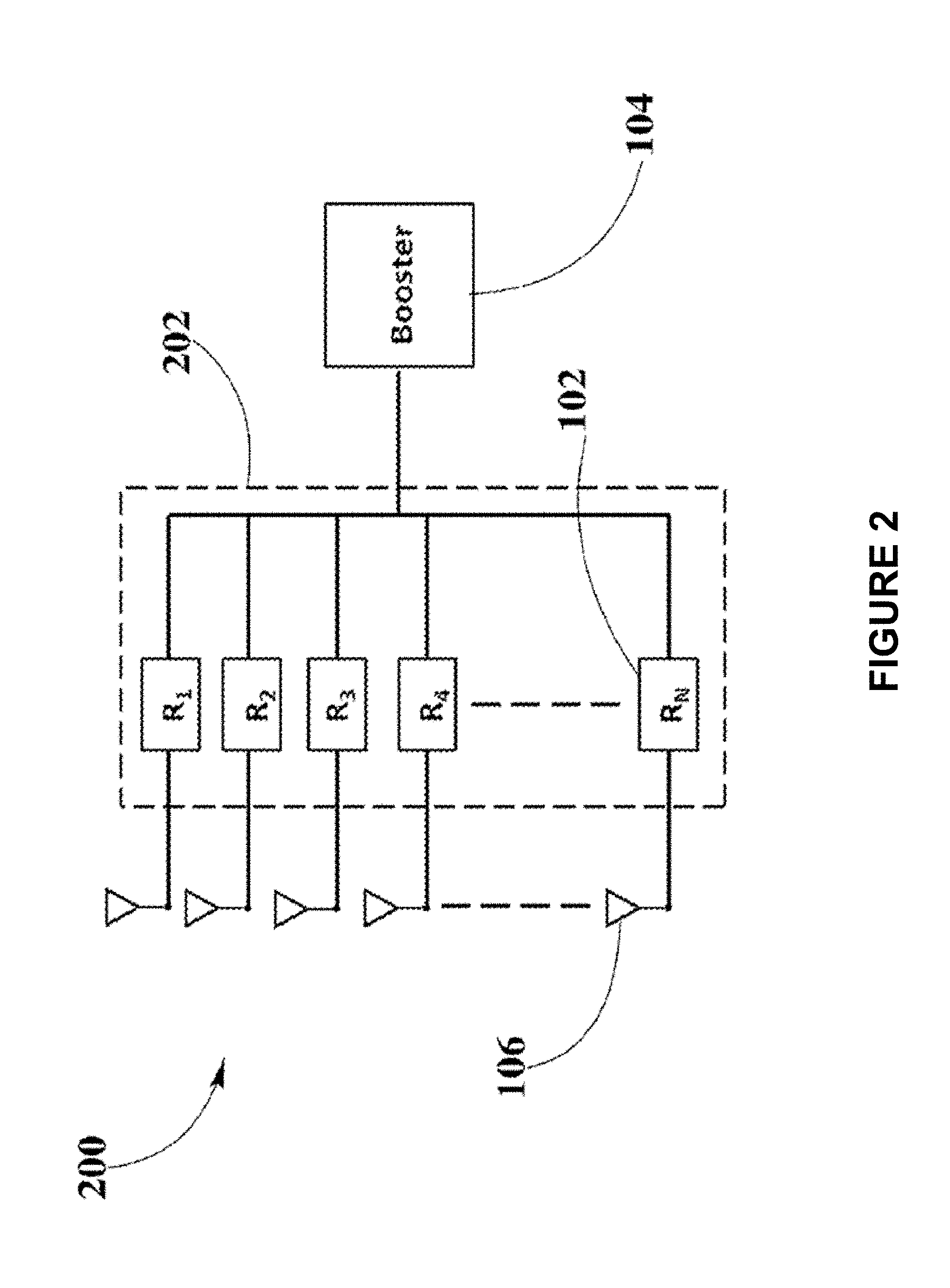
In accordance with one aspect of the present disclosure, the design of the integrated rectifier circuit architecture of present disclosure may include a plurality of identical topology-half-bridge rectifying circuits for power conversion, where the voltage output, alternating current (AC) waveforms, from a wireless transmitter may be received by same number of wireless receiver antennas as rectifying circuits may there be in the integrated rectifier architecture. The half-bridge rectifying circuits converting AC to direct current (DC) may be synchronous rectifiers. The integrated rectifier may include as many half-bridge rectifying circuits of identical topology as needed to supply the power levels required by the wireless receiver or the electronic device housing the wireless receiver.
In an embodiment, the integrated rectifier may be connected to a boost converter in which an integrated controller circuit may drive two control switches for power transfer to other modules of the wireless receiver. The integrated controller may be a programmable or non-programmable type controller. When one of the power switches is on for a particular amount of time, the output voltage from the integrated rectifier may charge an inductor increasing the current flowing through it. As the inductor may store energy, the voltage may increase to a predetermined level which may turn the other control switch on for a particular amount of time, providing the conduction path between the inductor and the output to discharge the inductor.
The charging inductor may be an external component of the integrated rectifier or may be included internally in the integrated rectifier. In one embodiment the charging inductor may be included in the boost converter circuit.
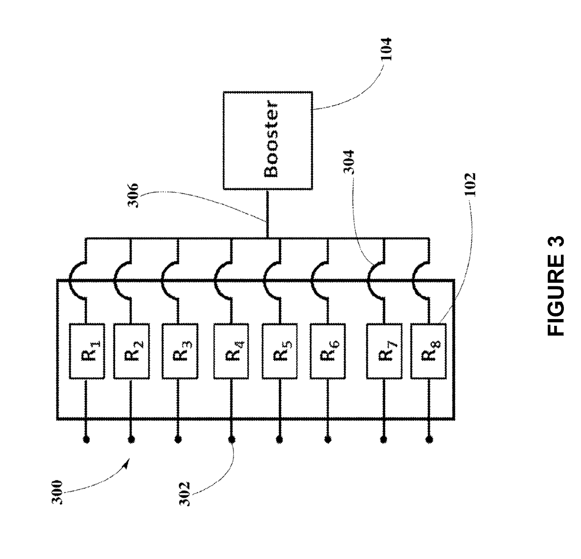
In another aspect, present disclosure may include an integrated rectifier with eight radio frequency (RF) voltage inputs connected to eight half-bridge rectifying circuits respectively, and eight DC outputs ganged together as a single feed into the boost converter.
The architecture of the integrated rectifier may be designed to be low cost, complexity, and size.
The architecture of the integrated rectifier may have the boost converter to control the current flowing out of the integrated rectifier with the plurality of half-bridge rectifying circuits to provide energy and capable of operating over a large range of frequencies.
The integrated rectifier may be enabled as an integrated circuit (IC), which may be much smaller than any discrete circuit made from independent components with known operational problems, such as operation over a large range of frequencies, and physical size design constraints. Half-bridge rectifiers in the IC may be synchronous rectifiers. In this embodiment, the charging inductor may be packaged with the integrated rectifier.
In yet another aspect of present disclosure, the boost converter controller may control the RF power that may be extracted and converted through the integrated rectifier architecture in the present disclosure by adding a comparator in the boost converter controller. The comparator may directly sense the extracted DC waveforms and compare their output voltage levels with a reference signal from the boost converter controller. For this, a proprietary algorithm may be employed to adjust the behavior of the boost converter controller in order to suit maximum power point tracking functionality.
In still another aspect of present disclosure, an external input may be added to the boost converter to connect an external micro-controller to provide additional feedback to the boost converter.
Numerous other aspects, features and benefits of the present disclosure may be made apparent from the following detailed description taken together with the drawing figures.
BRIEF DESCRIPTION OF THE DRAWINGS
The present disclosure can be better understood by referring to the following figures. The components in the figures are not necessarily to scale, emphasis instead being place upon illustrating the principles of the disclosure. In the figures, reference numerals designate corresponding parts throughout the different views.
FIG. 1 illustrates a schematic diagram of a circuit topology for an integrated rectifier and boost converter, according to an embodiment;
FIG. 2 depicts a block diagram of circuit architecture including antenna elements connected to integrated rectifier and boost converter, according to an embodiment;
FIG. 3 shows a block diagram of an integrated circuit of arrangement of rectifiers, according to an embodiment;
FIG. 4 represents a schematic diagram for a circuit topology of half-bridge rectifier power conversion controlled via a comparator, according to an embodiment; and
FIG. 5 depicts a schematic diagram for a circuit topology of half-bridge rectifier power conversion including an additional external micro-controller.
DETAILED DESCRIPTION
The present disclosure is here described in detail with reference to embodiments illustrated in the drawings, which form a part here. Other embodiments may be used and/or other changes may be made without departing from the spirit or scope of the present disclosure. The illustrative embodiments described in the detailed description are not meant to be limiting of the subject matter presented here.
Definitions
As used here, the following terms may have the following definitions:
"Electronic device" refers to a device depending on the principles of electronics and using the manipulation of electron flow for its operation. In present disclosure, refers to a device able to communicate using one or more suitable wireless technologies.
"Wireless receiver" refers to a device including at least one antenna element, at least one rectifying circuit and at least one power converter, which may utilize pockets of energy for powering, or charging a wireless device.
"Rectifier" refers to an electrical device that converts alternating current (AC), which periodically reverses direction, to direct current (DC), which flows in only one direction.
"Synchronous rectifier" refers to a power transmission circuit including active rectifiers controlled by switches such as transistors for improving the efficiency of rectification. The control circuitry for active rectification usually uses sensors for the voltage of the input AC to open the transistors at the correct times to allow current to flow in the correct direction.
"Switching transistor" refers to a semiconductor device used to switch electronic signals and electrical power in analog or digital circuits.
"Comparator" refers to a specialized high-gain differential amplifier used to measure and digitize analog signals, or to compare two voltages and determine whether a given input voltage is under voltage or over voltage.
Description of the Drawings
The present disclosure may provide rectifier architecture designed to include a circuit topology integrated with a boost converter for wireless receivers of a plurality of system configurations with maximum power transfer control. The design of the integrated rectifier circuit topology of present disclosure may include a plurality of half-bridge rectifiers whose power conversion and transmission may be controlled by switching devices in the boost converter. For power conversion in the integrated rectifier, the voltage output from a wireless transmitter is received by wireless receiver antenna elements and may be transferred as output voltage to other modules in the wireless receiver.
Simplified Circuit Topology of an Integrated Rectifier and Boost Converter
FIG. 1 illustrates a schematic diagram of a simplified circuit topology 100 for an integrated rectifier 102 and boost converter 104.
Present embodiment may include at least one antenna element 106 which may convert RF waves or pockets of energy into electrical power. Antenna element 106 may be operatively coupled with one or more rectifiers 102. RF waves may exhibit a sinusoidal shape within a voltage amplitude and power range that may depend on characteristics of a wireless power transmitter (not shown). Because of this sinusoidal nature of RF waves, the voltage or power generated by rectifier 102 may be variable. As an illustrative embodiment, and not by way of limitation, the alternating current (AC) voltage or power generated by antenna element 106 from transmitted RF waves or pocket of energy may vary from about 0 volts or 0 watt to about 5 volts at 3 watts.
Antenna element 106 may include suitable antenna types for operating in frequency bands similar to frequency bands, such as 900 MHz, 2.4 GHz, and 5.7 GHz, amongst others, from the wireless transmitter. These frequency bands comply with Federal Communications Commission (FCC) regulations part 18 (Industrial, Scientific and Medical equipment). Antenna element 106 may include vertical or horizontal polarization, right hand or left hand polarization, elliptical polarization, or other suitable polarizations as well as suitable polarization combinations. Using multiple polarizations may be beneficial in devices where there may not be a preferred orientation during usage or whose orientation may vary continuously through time. For devices with well-defined orientations, there might be a preferred polarization for antennas which may dictate a ratio for the number of antennas of a given polarization. Suitable antenna types may include patch antennas with heights from about 1/8 inches to about 6 inches and widths from about 1/8 inches to about 6 inches. Patch antennas may have the advantage that polarization may depend on connectivity, i.e. depending on which side the patch is fed, the polarization may change.
Rectifier 102 may include diodes, resistors, inductors, transistors and/or capacitors to rectify the AC voltage generated by antenna element 106 to direct current (DC) voltage. Rectifier 102 may be placed as close as technically possible to antenna element 106 to minimize losses. In one embodiment, rectifier 102 may operate in synchronous mode, in which case rectifier 102 may include switching elements, transistors, which may improve the efficiency of rectification. Half-bridge rectifier 102 may be used to produce an output with a fixed polarity that is independent of the polarity of the input.
Transmission of power converted by rectifier 102 may be controlled using either an active-drive approach to provide control signals with electronic circuitry which may have timing information from voltage or current waveforms within the power circuit, or a passive-drive approach in which control signals may be directly provided or through passive circuit elements from a waveform in the power circuit.
When an alternating RF signal is received by antenna element 106 from the wireless transmitter, a direct voltage output, V.sub.DC, may be drawn from the output terminals of half-bridge rectifier 102, including two diodes, D.sub.1 and D.sub.2, respectively identified as diode 108 and diode 110, which may be wired in series upstream and connected to the output terminal. Antenna element 106 is connected in series to capacitor 112, which is connected in series to inductor 114, both acting as the resonant filter for the power signal being transferred from wireless transmitter and received by antenna element 106. Additionally, rectifier 102 may be connected in parallel to a second filter capacitor 116 and in series with charging inductor 118.
When the polarity of the alternating RF signal received may be positive, current flows through the first upstream diode 108 and when the polarity of the alternating RF signal received is negative, current flows through second upstream diode 110.
Boost converter 104 may include charging inductor 118, but it may be laid out internally of rectifier 102. In the present embodiment inductor 118 may be preferably laid out as an internal component of boost converter 104 and may be designed with an appropriate, smaller form factor and scaled to a plurality of values, such that maximum power that may be converted may not saturate inductor 118. Boost converter 104 may convert the variable DC output voltage of rectifier 102 into a more stable DC voltage that can be used by components of a wireless receiver and/or electronic device housing the wireless receiver. Boost converter 104 may operate as a step-up DC-to-DC converter to increase the voltage from rectifier 102 to a voltage level suitable for proper operation of other modules in the wireless receiver. In addition, boost converter 104 may reduce or eliminate rail-to-rail deviations. Additional filtering capabilities, capacitor 126, may be added at the output of boost converter 104 as shown in FIG. 1. In one embodiment, boost converter 104 may exhibit a synchronous topology to increase power conversion efficiency.
As the voltage or power generated from RF waves may be zero at some instants of wireless power transmission, circuit topology 100 may include circuit elements to store energy or electric charge from the output voltage produced by rectifier 102. In this way, inductor 118, may deliver continuous voltage or power to the output terminal of boost converter 104, where a load (not shown) may represent a battery or internal circuitry of electronic device requiring continuous powering or charging.
When the required level of voltage may be present at the output terminal of rectifier 102, micro-controller 120 may turn switching transistor 122, Q.sub.1, on for current to flow through inductor 118, which may start storing energy. Then, according to a predetermined control switching scheme in micro-controller 120, switching transistor 122 may be turned off. Subsequently, inductor 118 may discharge its stored energy by sending current to switching transistor 124, Q.sub.2, which may be presently in off state. Due to this current and the state of switching transistor 124, the voltage may rise at the input of switching transistor 124. At some level of voltage in accordance with the switching control scheme, micro-controller 120 may turn switching transistor 124 on for a particular amount of time allowing energy transmission at a level of voltage that is higher than the original voltage at capacitor 116, C.sub.2. Switching transistors 122, 124 may be identical field-effect transistors, bipolar junction transistors, insulated-gate bipolar transistors, or gallium nitride transistors, amongst others.
Micro-controller 120 may be an integrated controller circuit driving switching transistor 122, 124 for power transfer to other modules of the wireless receiver and it may be a programmable or non-programmable type controller.
Circuit Architecture of an Integrated Rectifier and Boost Converter
FIG. 2 depicts a block diagram of circuit architecture 200 including antenna elements 106 connected to integrated rectifier 202 and boost converter 104, according to an embodiment.
Better efficiency and power density may not be achieved using one sole rectifier 102 as shown in FIG. 1. The well-known problem of power availability at the output of a wireless receiver may be solved using circuit architecture 200 including a plurality of identical rectifiers 102, as described in circuit topology 100, including same passive and active circuit components and switching control schemes, and integrated as rectifier 202, connected to boost converter 104. Accordingly, multiple configurations may be used to transfer wireless power from antenna elements 106. This way, integrated rectifier 202 may include as many identical rectifiers 102 as required by the power level that may be needed for a wireless receiver to operate efficiently, as well as the electronic device housing the wireless receiver. Integrated rectifier 202 may include from one to N identical rectifiers 102, R.sub.1, R.sub.2, R.sub.3 . . . R.sub.N, feeding one boost converter 104.
In one embodiment, inductor 118 may be included in the circuit topology of integrated rectifier 202. In another embodiment inductor 118 may be externally placed next to boost converter 104. The size and shape of the external inductor 118 may depend on the electrical constraints and parameters of the circuit.
As may be seen in FIG. 2, circuit architecture 200 may allow to have two rectifiers 102, or four rectifiers 102, or eight rectifiers 102, as integrated rectifier 202, each connected to a dedicated antenna element 106 and the total power output feeding one boost converter 104.
Integrated Circuit of Rectifiers and Boost Converter
FIG. 3 shows a block diagram of integrated circuit 300 of arrangement of rectifiers 102, according to an embodiment.
Given that circuit architecture 200, including rectifiers 102 of circuit topology 100, may be an expensive implementation using discrete components for rectifier 102, a configuration of eight rectifiers 102 may be enabled in integrated circuit 300.
Integrated circuit 300 may include eight RF input terminals 302, eight rectifiers 102, and eight DC output lines 304 connected together to provide the total power extracted from RF signals received by antenna elements 106 through a single feed line 306 into boost converter 104. Integrated circuit 300 may also include synchronous half-bridge rectifiers 102.
Additionally, integrated circuit 300 may enable an implementation of circuit architecture 200 that may be capable of operating over a large range of frequencies. This capability may not be possible using discrete components. Moreover, inductor 118, shown in FIG. 1, may be included in integrated circuit 300 and physically sized to smaller form factor and value such that maximum power extracted and converted may not saturate inductor 118.
Capacitor 116 in each rectifier 102 may be substituted in the package by the layout of bonded wires used for output lines 304, thus significantly reducing the size of integrated circuit 300 and increasing power transmission efficiency.
Control-Driven Integrated Rectifier and Boost Converter Circuit Topology
FIG. 4 represents a schematic diagram for a circuit topology 400 of half-bridge rectifier 102 power conversion controlled via a comparator 402, according to an embodiment.
Circuit architecture 200 may include micro-controller 120, in boost converter 104, to control the RF power that may be extracted. Micro-controller 120 may drive comparator 402 to which a reference signal, V.sub.REF, may be fed to compare it with the extracted DC waveforms and enabling a proprietary algorithm to turn switch transistors 122, 124 on at the appropriate voltage point and particular amount of time to suit maximum power point tracking (MPPT) functionality, charging and discharging inductor 118 as described in FIG. 1. All other circuit elements in circuit topology 400 are the same as in circuit topology 100 in FIG. 1. Directly sensing of the output voltage, V.sub.DC, may be performed by comparator 402 to see if it is below of a predetermined design voltage threshold.
Micro-controller 120, based on voltage measurements, may control the power or voltage delivered at the output terminals of boost converter 104, and therefore, adjust the current limits supplied to other modules in the wireless receiver.
An MPPT algorithm may be executed by micro-controller 120 to control and optimize the amount of power that boost converter 104 may pull from antenna elements 106. Accordingly, MPPT functionality may be enabled having micro-controller 120 to monitor the power levels converted. Subsequently, the comparison of DC voltage at the output terminal of rectifier 102, V.sub.DC, with the voltage reference, V.sub.REF, may be used by micro-controller 120 to detect the maximum power point in the RF signals received by antenna elements 106 and for the proprietary algorithm to adjust the level of power extracted in conformity with the MPPT data in micro-controller 120.
This active-drive approach of control may be also implemented including comparator 402 in integrated circuit 300.
FIG. 5 represents a schematic diagram for a circuit topology 500 of half-bridge rectifier 102 power conversion including an additional external system micro-controller 502, according to an embodiment.
Circuit topology 500 may include all components in circuit topology 400, to which the external system micro-controller 502 may be added to provide additional control of boost converter 104 in a wireless receiver (not shown).
Micro-controller 120 in circuit topology 400, may drive comparator 402 to which a reference signal, V.sub.REF, may be fed to compare it with the extracted DC waveforms and enabling a proprietary algorithm to turn switch transistors 122, 124 on at the appropriate voltage point and particular amount of time to suit maximum power point tracking (MPPT) functionality, charging and discharging inductor 118. This active-drive approach of control may be also implemented including comparator 402 in integrated circuit 300.
System micro-controller 502 may process information sent by the wireless receiver through its communications component for determining optimum times and locations for pocket-forming and may also operate in conjunction with an EEPROM module to run an algorithm for controlling the operation of boost converter 104 according to load requirements. System micro-controller 502 may actively monitor the overall operation of the wireless receiver by taking one or more power measurements at different nodes or sections of the wireless receiver. For example, system micro-controller 502 may measure how much voltage or power is being delivered at rectifier 102, boost converter 104, and other components in the wireless receiver, including the connected load and may communicate these power measurements to the connected load so that electronic device may know how much power it can pull from the wireless receiver. System micro-controller 502 may provide additional feedback to the boost converter 104.
While various aspects and embodiments have been disclosed, other aspects and embodiments may be contemplated. The various aspects and embodiments disclosed here are for purposes of illustration and are not intended to be limiting, with the true scope and spirit being indicated by the following claims.
* * * * *
D00000
D00001
D00002
D00003
D00004
D00005
XML
uspto.report is an independent third-party trademark research tool that is not affiliated, endorsed, or sponsored by the United States Patent and Trademark Office (USPTO) or any other governmental organization. The information provided by uspto.report is based on publicly available data at the time of writing and is intended for informational purposes only.
While we strive to provide accurate and up-to-date information, we do not guarantee the accuracy, completeness, reliability, or suitability of the information displayed on this site. The use of this site is at your own risk. Any reliance you place on such information is therefore strictly at your own risk.
All official trademark data, including owner information, should be verified by visiting the official USPTO website at www.uspto.gov. This site is not intended to replace professional legal advice and should not be used as a substitute for consulting with a legal professional who is knowledgeable about trademark law.