Stereo yaw correction using autofocus feedback
Ramachandra , et al. J
U.S. patent number 10,178,373 [Application Number 14/250,798] was granted by the patent office on 2019-01-08 for stereo yaw correction using autofocus feedback. This patent grant is currently assigned to QUALCOMM Incorporated. The grantee listed for this patent is QUALCOMM Incorporated. Invention is credited to Kalin Mitkov Atanassov, Vikas Ramachandra, Ruben Manuel Velarde.


| United States Patent | 10,178,373 |
| Ramachandra , et al. | January 8, 2019 |
Stereo yaw correction using autofocus feedback
Abstract
Systems and methods for correcting stereo yaw of a stereoscopic image sensor pair using autofocus feedback are disclosed. A stereo depth of an object in an image is estimated from the disparity of the object between the images captured by each sensor of the image sensor pair. An autofocus depth to the object is found from the autofocus lens position. If the difference between the stereo depth and the autofocus depth is non zero, one of the images is warped and the disparity is recalculated until the stereo depth and the autofocus depth to the object is substantially the same.
| Inventors: | Ramachandra; Vikas (San Diego, CA), Atanassov; Kalin Mitkov (San Diego, CA), Velarde; Ruben Manuel (Chula Vista, CA) | ||||||||||
|---|---|---|---|---|---|---|---|---|---|---|---|
| Applicant: |
|
||||||||||
| Assignee: | QUALCOMM Incorporated (San
Diego, CA) |
||||||||||
| Family ID: | 52466554 | ||||||||||
| Appl. No.: | 14/250,798 | ||||||||||
| Filed: | April 11, 2014 |
Prior Publication Data
| Document Identifier | Publication Date | |
|---|---|---|
| US 20150049172 A1 | Feb 19, 2015 | |
Related U.S. Patent Documents
| Application Number | Filing Date | Patent Number | Issue Date | ||
|---|---|---|---|---|---|
| 61866950 | Aug 16, 2013 | ||||
| Current U.S. Class: | 1/1 |
| Current CPC Class: | H04N 13/239 (20180501); G06T 7/571 (20170101); G06T 7/85 (20170101); H04N 13/246 (20180501) |
| Current International Class: | H04N 13/246 (20180101); H04N 13/239 (20180101); G06T 7/80 (20170101); G06T 7/571 (20170101) |
References Cited [Referenced By]
U.S. Patent Documents
| 3698803 | October 1972 | Toshio |
| 4114171 | September 1978 | Altman |
| 4437745 | March 1984 | Hajnal |
| 4639586 | January 1987 | Fender et al. |
| 4740780 | April 1988 | Brown et al. |
| 4751570 | June 1988 | Robinson |
| 4890314 | December 1989 | Judd et al. |
| 5012273 | April 1991 | Nakamura et al. |
| 5016109 | May 1991 | Gaylord |
| 5063441 | November 1991 | Lipton et al. |
| 5142357 | August 1992 | Lipton et al. |
| 5194959 | March 1993 | Kaneko et al. |
| 5207000 | May 1993 | Chang et al. |
| 5231461 | July 1993 | Silvergate et al. |
| 5243413 | September 1993 | Gitlin et al. |
| 5313542 | May 1994 | Castonguay |
| 5475617 | December 1995 | Castonguay |
| 5506913 | April 1996 | Ibison et al. |
| 5539483 | July 1996 | Nalwa |
| 5606627 | February 1997 | Kuo |
| 5614941 | March 1997 | Hines |
| 5640222 | June 1997 | Paul |
| 5642299 | June 1997 | Hardin et al. |
| 5686960 | November 1997 | Sussman et al. |
| 5721585 | February 1998 | Keast et al. |
| 5734507 | March 1998 | Harvey |
| 5745305 | April 1998 | Nalwa |
| 5760846 | June 1998 | Lee |
| 5793527 | August 1998 | Nalwa |
| 5798791 | August 1998 | Katayama et al. |
| 5903306 | May 1999 | Heckendorn et al. |
| 5926411 | July 1999 | Russell |
| 5990934 | November 1999 | Nalwa |
| 6111702 | August 2000 | Nalwa |
| 6115176 | September 2000 | Nalwa |
| 6128143 | October 2000 | Nalwa |
| 6141034 | October 2000 | McCutchen |
| 6141145 | October 2000 | Nalwa |
| 6144501 | November 2000 | Nalwa |
| 6195204 | February 2001 | Nalwa |
| 6219090 | April 2001 | Nalwa |
| 6285365 | September 2001 | Nalwa |
| 6356397 | March 2002 | Nalwa |
| 6421185 | July 2002 | Wick et al. |
| 6445815 | September 2002 | Sato |
| 6611289 | August 2003 | Yu et al. |
| 6628897 | September 2003 | Suzuki |
| 6650774 | November 2003 | Szeliski |
| 6700711 | March 2004 | Nalwa |
| 6701081 | March 2004 | Dwyer et al. |
| 6768509 | July 2004 | Bradski et al. |
| 6775437 | August 2004 | Kazarinov et al. |
| 6782137 | August 2004 | Avinash |
| 6798406 | September 2004 | Jones et al. |
| 6809887 | October 2004 | Gao et al. |
| 6850279 | February 2005 | Scherling |
| 6855111 | February 2005 | Yokoi et al. |
| 6861633 | March 2005 | Osborn |
| 6862364 | March 2005 | Berestov |
| 6987534 | January 2006 | Seta |
| 6992700 | January 2006 | Sato et al. |
| 7006123 | February 2006 | Yoshikawa et al. |
| 7039292 | May 2006 | Breiholz |
| 7084904 | August 2006 | Liu et al. |
| 7116351 | October 2006 | Yoshikawa |
| 7215479 | May 2007 | Bakin |
| 7253394 | August 2007 | Kang |
| 7271803 | September 2007 | Ejiri et al. |
| 7336299 | February 2008 | Kostrzewski et al. |
| 7612953 | November 2009 | Nagai et al. |
| 7710463 | May 2010 | Foote |
| 7805071 | September 2010 | Mitani |
| 7817354 | October 2010 | Wilson et al. |
| 7860214 | December 2010 | Haff |
| 7893957 | February 2011 | Peters et al. |
| 7961398 | June 2011 | Tocci |
| 7978222 | July 2011 | Schneider |
| 8004557 | August 2011 | Pan |
| 8098276 | January 2012 | Chang et al. |
| 8115813 | February 2012 | Tang |
| 8139125 | March 2012 | Scherling |
| 8228417 | July 2012 | Georgiev et al. |
| 8267601 | September 2012 | Campbell et al. |
| 8284263 | October 2012 | Oohara et al. |
| 8294073 | October 2012 | Vance et al. |
| 8356035 | January 2013 | Baluja et al. |
| 8400555 | March 2013 | Georgiev et al. |
| 8442392 | May 2013 | Ollila et al. |
| 8482813 | July 2013 | Kawano et al. |
| 8791984 | July 2014 | Jones et al. |
| 8836693 | September 2014 | Katano |
| 8928988 | January 2015 | Ford et al. |
| 8988564 | March 2015 | Webster et al. |
| 9049375 | June 2015 | Wade et al. |
| 9055208 | June 2015 | Kim |
| 9185296 | November 2015 | Wade et al. |
| 9264610 | February 2016 | Duparre |
| 9294672 | March 2016 | Georgiev et al. |
| 9316810 | April 2016 | Mercado |
| 9332188 | May 2016 | Takei et al. |
| 9602806 | March 2017 | Stafford |
| 9609210 | March 2017 | Djordjevic et al. |
| 9952371 | April 2018 | Ambur et al. |
| 9973680 | May 2018 | Osborne et al. |
| 2001/0028482 | October 2001 | Nishioka |
| 2002/0070365 | June 2002 | Karellas |
| 2002/0136150 | September 2002 | Mihara et al. |
| 2003/0024987 | February 2003 | Zhu |
| 2003/0034395 | February 2003 | Tsikos et al. |
| 2003/0038814 | February 2003 | Blume |
| 2003/0156751 | August 2003 | Lee |
| 2003/0214575 | November 2003 | Yoshikawa |
| 2004/0021767 | February 2004 | Endo et al. |
| 2004/0051805 | March 2004 | Yoshikawa et al. |
| 2004/0066449 | April 2004 | Givon |
| 2004/0105025 | June 2004 | Scherling |
| 2004/0183907 | September 2004 | Hovanky et al. |
| 2004/0195492 | October 2004 | Hsin |
| 2004/0201769 | October 2004 | Yoshikawa et al. |
| 2004/0246333 | December 2004 | Steuart et al. |
| 2004/0263611 | December 2004 | Cutler |
| 2005/0053274 | March 2005 | Mayer et al. |
| 2005/0057659 | March 2005 | Hasegawa |
| 2005/0081629 | April 2005 | Hoshal |
| 2005/0111106 | May 2005 | Matsumoto et al. |
| 2005/0185711 | August 2005 | Pfister et al. |
| 2005/0218297 | October 2005 | Suda et al. |
| 2005/0243175 | November 2005 | Yamada et al. |
| 2005/0253951 | November 2005 | Fujimoto et al. |
| 2006/0023074 | February 2006 | Cutler |
| 2006/0023106 | February 2006 | Yee et al. |
| 2006/0023278 | February 2006 | Nishioka |
| 2006/0061660 | March 2006 | Brackmann |
| 2006/0084852 | April 2006 | Mason et al. |
| 2006/0098267 | May 2006 | Togawa |
| 2006/0140446 | June 2006 | Luo et al. |
| 2006/0193509 | August 2006 | Criminisi et al. |
| 2006/0215054 | September 2006 | Liang et al. |
| 2006/0215903 | September 2006 | Nishiyama |
| 2006/0238441 | October 2006 | Benjamin et al. |
| 2007/0024739 | February 2007 | Konno |
| 2007/0058961 | March 2007 | Kobayashi et al. |
| 2007/0064142 | March 2007 | Misawa et al. |
| 2007/0085903 | April 2007 | Zhang |
| 2007/0146530 | June 2007 | Nose |
| 2007/0164202 | July 2007 | Wurz et al. |
| 2007/0216796 | September 2007 | Lenel et al. |
| 2007/0242152 | October 2007 | Chen |
| 2007/0263115 | November 2007 | Horidan et al. |
| 2007/0268983 | November 2007 | Elam |
| 2008/0029708 | February 2008 | Olsen et al. |
| 2008/0030573 | February 2008 | Ritchey |
| 2008/0030597 | February 2008 | Olsen et al. |
| 2008/0058629 | March 2008 | Seibel et al. |
| 2008/0088702 | April 2008 | Linsenmaier et al. |
| 2008/0117289 | May 2008 | Schowengerdt et al. |
| 2008/0117532 | May 2008 | Shafer |
| 2008/0218612 | September 2008 | Border et al. |
| 2008/0259172 | October 2008 | Tamaru |
| 2008/0266404 | October 2008 | Sato |
| 2008/0290435 | November 2008 | Oliver et al. |
| 2008/0291543 | November 2008 | Nomura et al. |
| 2008/0297612 | December 2008 | Yoshikawa |
| 2008/0316301 | December 2008 | Givon |
| 2009/0003646 | January 2009 | Au et al. |
| 2009/0005112 | January 2009 | Sorek et al. |
| 2009/0015812 | January 2009 | Schultz et al. |
| 2009/0051804 | February 2009 | Nomura et al. |
| 2009/0080695 | March 2009 | Yang |
| 2009/0085846 | April 2009 | Cho et al. |
| 2009/0096994 | April 2009 | Smits |
| 2009/0153726 | June 2009 | Lim |
| 2009/0160931 | June 2009 | Pockett et al. |
| 2009/0268210 | October 2009 | Prince |
| 2009/0268983 | October 2009 | Stone et al. |
| 2009/0268985 | October 2009 | Wong |
| 2009/0296984 | December 2009 | Nijim et al. |
| 2009/0315808 | December 2009 | Ishii |
| 2010/0044555 | February 2010 | Ohara et al. |
| 2010/0045774 | February 2010 | Len et al. |
| 2010/0066812 | March 2010 | Kajihara et al. |
| 2010/0165155 | July 2010 | Chang |
| 2010/0202766 | August 2010 | Takizawa et al. |
| 2010/0215249 | August 2010 | Heitz et al. |
| 2010/0232681 | September 2010 | Fujieda et al. |
| 2010/0259655 | October 2010 | Takayama |
| 2010/0265313 | October 2010 | Liu et al. |
| 2010/0265363 | October 2010 | Kim |
| 2010/0278423 | November 2010 | Itoh et al. |
| 2010/0289878 | November 2010 | Sato et al. |
| 2010/0290703 | November 2010 | Sim et al. |
| 2010/0290769 | November 2010 | Nasiri et al. |
| 2010/0302396 | December 2010 | Golub et al. |
| 2010/0309286 | December 2010 | Chen et al. |
| 2010/0309333 | December 2010 | Smith et al. |
| 2011/0001789 | January 2011 | Wilson et al. |
| 2011/0007135 | January 2011 | Okada et al. |
| 2011/0009163 | January 2011 | Fletcher et al. |
| 2011/0012998 | January 2011 | Pan |
| 2011/0038535 | February 2011 | Wang et al. |
| 2011/0043623 | February 2011 | Fukuta et al. |
| 2011/0090575 | April 2011 | Mori |
| 2011/0096089 | April 2011 | Shenhav et al. |
| 2011/0096988 | April 2011 | Suen et al. |
| 2011/0128412 | June 2011 | Milnes et al. |
| 2011/0181588 | July 2011 | Barenbrug |
| 2011/0213664 | September 2011 | Osterhout et al. |
| 2011/0235899 | September 2011 | Tanaka |
| 2011/0249341 | October 2011 | DiFrancesco et al. |
| 2011/0262122 | October 2011 | Minamisawa et al. |
| 2011/0304764 | December 2011 | Shigemitsu et al. |
| 2012/0008148 | January 2012 | Pryce et al. |
| 2012/0033051 | February 2012 | Atanassov et al. |
| 2012/0044368 | February 2012 | Lin et al. |
| 2012/0056987 | March 2012 | Fedoroff |
| 2012/0075168 | March 2012 | Osterhout et al. |
| 2012/0127276 | May 2012 | Tsai |
| 2012/0229688 | September 2012 | Tajiri |
| 2012/0249536 | October 2012 | Sutou |
| 2012/0249750 | October 2012 | Izzat et al. |
| 2012/0249815 | October 2012 | Bohn et al. |
| 2012/0269400 | October 2012 | Heyward |
| 2012/0281072 | November 2012 | Georgiev et al. |
| 2012/0293607 | November 2012 | Bhogal et al. |
| 2012/0293632 | November 2012 | Yukich |
| 2012/0327195 | December 2012 | Cheng |
| 2013/0003140 | January 2013 | Keniston et al. |
| 2013/0010084 | January 2013 | Hatano |
| 2013/0038689 | February 2013 | McDowall |
| 2013/0057655 | March 2013 | Su |
| 2013/0070055 | March 2013 | Atanassov et al. |
| 2013/0076924 | March 2013 | Wade et al. |
| 2013/0077945 | March 2013 | Liu et al. |
| 2013/0128030 | May 2013 | Georgiev |
| 2013/0141802 | June 2013 | Yang |
| 2013/0182325 | July 2013 | Minamisawa et al. |
| 2013/0222556 | August 2013 | Shimada |
| 2013/0229529 | September 2013 | Lablans |
| 2013/0250045 | September 2013 | Ki et al. |
| 2013/0250053 | September 2013 | Levy |
| 2013/0250123 | September 2013 | Zhang et al. |
| 2013/0260823 | October 2013 | Shukla et al. |
| 2013/0278785 | October 2013 | Nomura et al. |
| 2013/0286451 | October 2013 | Verhaegh |
| 2013/0329015 | December 2013 | Pulli |
| 2013/0335598 | December 2013 | Gustavsson et al. |
| 2013/0335600 | December 2013 | Gustavsson et al. |
| 2014/0009631 | January 2014 | Topliss |
| 2014/0016832 | January 2014 | Kong et al. |
| 2014/0085502 | March 2014 | Lin et al. |
| 2014/0104378 | April 2014 | Kauff et al. |
| 2014/0111650 | April 2014 | Georgiev et al. |
| 2014/0139623 | May 2014 | McCain et al. |
| 2014/0152852 | June 2014 | Ito et al. |
| 2014/0184749 | July 2014 | Hilliges et al. |
| 2014/0192253 | July 2014 | Laroia |
| 2014/0285673 | September 2014 | Hundley et al. |
| 2014/0340568 | November 2014 | Sano et al. |
| 2015/0043076 | February 2015 | Nakayama |
| 2015/0070562 | March 2015 | Nayar et al. |
| 2015/0085363 | March 2015 | Liu et al. |
| 2015/0125092 | May 2015 | Zhuo et al. |
| 2015/0177524 | June 2015 | Webster et al. |
| 2015/0201128 | July 2015 | Dong |
| 2015/0244934 | August 2015 | Duparre et al. |
| 2015/0253647 | September 2015 | Mercado |
| 2015/0286033 | October 2015 | Osborne |
| 2015/0288865 | October 2015 | Osborne |
| 2015/0370040 | December 2015 | Georgiev |
| 2015/0371387 | December 2015 | Atanassov |
| 2015/0373252 | December 2015 | Georgiev |
| 2015/0373263 | December 2015 | Georgiev |
| 2015/0373268 | December 2015 | Osborne |
| 2015/0373269 | December 2015 | Osborne |
| 2015/0373279 | December 2015 | Osborne |
| 2016/0014332 | January 2016 | De et al. |
| 2016/0085059 | March 2016 | Mercado |
| 2016/0127641 | May 2016 | Gove |
| 2016/0127646 | May 2016 | Osborne |
| 2016/0198087 | July 2016 | Georgiev et al. |
| 2016/0269602 | September 2016 | Osborne |
| 2016/0286121 | September 2016 | Georgiev et al. |
| 2016/0295112 | October 2016 | Georgiev et al. |
| 2016/0353008 | December 2016 | Osborne |
| 2016/0373263 | December 2016 | Zaidi et al. |
| 2017/0026570 | January 2017 | Shepard et al. |
| 2017/0038502 | February 2017 | Georgiev |
| 2017/0118421 | April 2017 | Georgiev |
| 2018/0084193 | March 2018 | Georgiev et al. |
| 101046534 | Oct 2007 | CN | |||
| 101065955 | Oct 2007 | CN | |||
| 101201459 | Jun 2008 | CN | |||
| 101257576 | Sep 2008 | CN | |||
| 101571666 | Nov 2009 | CN | |||
| 101581828 | Nov 2009 | CN | |||
| 101867720 | Oct 2010 | CN | |||
| 101902657 | Dec 2010 | CN | |||
| 101926171 | Dec 2010 | CN | |||
| 101952762 | Jan 2011 | CN | |||
| 201917706 | Aug 2011 | CN | |||
| 202405984 | Aug 2012 | CN | |||
| 103038689 | Apr 2013 | CN | |||
| 103376613 | Oct 2013 | CN | |||
| 203519911 | Apr 2014 | CN | |||
| 203519914 | Apr 2014 | CN | |||
| 203551875 | Apr 2014 | CN | |||
| 0610605 | Aug 1994 | EP | |||
| 0751416 | Jan 1997 | EP | |||
| 1176812 | Jan 2002 | EP | |||
| 1383342 | Jan 2004 | EP | |||
| 1816514 | Aug 2007 | EP | |||
| 1832912 | Sep 2007 | EP | |||
| 2242252 | Oct 2010 | EP | |||
| 2354390 | Mar 2001 | GB | |||
| 2354391 | Mar 2001 | GB | |||
| S60213178 | Oct 1985 | JP | |||
| H06217184 | Aug 1994 | JP | |||
| H06251127 | Sep 1994 | JP | |||
| H089424 | Jan 1996 | JP | |||
| H0847001 | Feb 1996 | JP | |||
| H08125835 | May 1996 | JP | |||
| 8194274 | Jul 1996 | JP | |||
| H08242453 | Sep 1996 | JP | |||
| H0946729 | Feb 1997 | JP | |||
| H09214992 | Aug 1997 | JP | |||
| H10142490 | May 1998 | JP | |||
| 2001194114 | Jul 2001 | JP | |||
| 2002158913 | May 2002 | JP | |||
| 2003304561 | Oct 2003 | JP | |||
| 2004260787 | Sep 2004 | JP | |||
| 3791847 | Jun 2006 | JP | |||
| 2006279538 | Oct 2006 | JP | |||
| 2007147457 | Jun 2007 | JP | |||
| 2007323615 | Dec 2007 | JP | |||
| 2008009424 | Jan 2008 | JP | |||
| 2009122842 | Jun 2009 | JP | |||
| 2010041381 | Feb 2010 | JP | |||
| 2010067014 | Mar 2010 | JP | |||
| 2010128820 | Jun 2010 | JP | |||
| 2010524279 | Jul 2010 | JP | |||
| 2012085102 | Apr 2012 | JP | |||
| 2013117568 | Jun 2013 | JP | |||
| 20060049992 | May 2006 | KR | |||
| 20080071400 | Aug 2008 | KR | |||
| WO-199321560 | Oct 1993 | WO | |||
| WO-199847291 | Oct 1998 | WO | |||
| WO-2006075528 | Jul 2006 | WO | |||
| WO-2007129147 | Nov 2007 | WO | |||
| WO-2008112054 | Sep 2008 | WO | |||
| WO-2009047681 | Apr 2009 | WO | |||
| WO-2009086330 | Jul 2009 | WO | |||
| WO-2010019757 | Feb 2010 | WO | |||
| 2011108276 | Sep 2011 | WO | |||
| WO-2012136388 | Oct 2012 | WO | |||
| WO-2012164339 | Dec 2012 | WO | |||
| WO-2013154433 | Oct 2013 | WO | |||
| WO-2014012603 | Jan 2014 | WO | |||
| WO-2014025588 | Feb 2014 | WO | |||
Other References
|
Arican, et al., "Intermediate View Generation for Perceived Depth Adjustment of Sterio Video", Mitsubishi Electric Research Laboratories, http://www.merl.com, TR2009-052, Sep. 2009; 12 pages. cited by applicant . Hoff, et al., "Surfaces from Stereo: Integrating Feature Matching, Disparity Estimation, and Contour Detection", IEEE Transactions on Pattern Analysis and Machine Intelligence, vol. 11, No. 2, pp. 121-136, Feb. 1989. cited by applicant . International Search Report and Written Opinion--PCT/US2014/049776--ISA/EPO--dated Nov. 14, 2014. cited by applicant . Krotkov E., et al., "Active vision for reliable ranging: Cooperating focus, stereo, and vergence", International Journal of Computer Vision. vol. 11, No. 2, Oct. 1, 1993 (Oct. 1, 1993), pp. 187-203, XP055149875, ISSN: 0920-5691. DOI: 10.1007/BF01469228. cited by applicant . Murphy M., et al., "Lens Drivers Focus on Performance in High-Resolution Camera Modules," Analog Dialogue, Nov. 2006, vol. 40, pp. 1-3. cited by applicant . Narkhede, et al., "Stereoscopic Imaging: A Real-Time, in Depth Look," IEEE Potentials, Feb./Mar. 2004, vol. 23, Issue 1, pp. 38-42. cited by applicant . Sun W.S., et al., "Single-Lens Camera Based on a Pyramid Prism Array to Capture Four Images," Optical Review, 2013, vol. 20 (2), pp. 145-152. cited by applicant . Han Y., et al., "Removing Illumination from Image Pair for Stereo Matching", Audio, Language and Image Processing (ICALIP), 2012 International Conference on, IEEE, Jul. 16, 2012, XP032278010, pp. 508-512. cited by applicant . Hao M., et al., "Object Location Technique for Binocular Stereo Vision Based on Scale Invariant Feature Transform Feature Points", SIFT, Journal of Harbin Engineering University, Jun. 2009, vol. 30, No. 6 pp. 649-653. cited by applicant . Kawanishi T., et al., "Generation of High-Resolution Stereo Panoramic Images by Omnidirectional Imaging Sensor Using Hexagonal Pyramidal Mirrors", Pattern Recognition, 1998, Proceedings, Fourteenth International Conference on Brisbane, QLD., Australia Aug. 16-20, 1998, Los Alamitos, CA, USA,IEEE Comput. Soc, US, Jan. 1, 1998 (Jan. 1, 1998), pp. 485-489, vol. 1, XP031098377, ISBN: 978-0-8186-8512-5. cited by applicant . Ricoh Imagine Change: "New Ricoh Theta Model, Capturing 360-degree Images in One Shot, is on Sale Soon--Spherical Video Function, API and SDK (Beta Version)", News Release, Oct. 28, 2014, 3 pages. cited by applicant . Shuchun Y., et al., "Preprocessing for stereo vision based on LOG filter", Proceedings of 2011 6th International Forum on Strategic Technology, Aug. 2011, XP055211077, pp. 1074-1077. cited by applicant . Tan K-H., et al., "Multiview Panoramic Cameras Using a Pyramid", Omnidirectional Vision, 2002, Proceedings, Third Workshop on Jun. 2, 2002, Piscataway, NJ, USA,IEEE, Jan. 1, 2002 (Jan. 1, 2002), pp. 87-93, XP010611080, ISBN: 978-0-7695-1629-5. cited by applicant . Hua et al., "Design Analysis of a High-Resolution Panoramic Camera Using Conventional Imagers and a Mirror Pyramid," IEEE Transactions on Pattern Analysis and Machine Intelligence; Feb. 2007; 29(2): 356-361. cited by applicant . Meng et al., "Single-shot Specular Surface Reconstruction with Gonio-plenoptic Imaging," 2015 IEEE International Conference on Computer Vision; pp. 3433-3441. cited by applicant . Chowdhury A., et al., "Challenges of Megapixel Camera Module Assembly and Test," Electronic Components and Technology Conference, 2005, pp. 1390-1401. cited by applicant . Hung K-Y., et al., "Integrated the Back-Side Inclined Exposure Technology to Fabricate the 45 Degree K-Type Prism with Nanometer Roughness," NEMS 2012, Kyoto, Japan, Mar. 2012, pp. 120-124. cited by applicant . Wenyi Zhao and N. Nandhakumar, "Effects of Camera Alignment Errors on Stereoscopic Depth Estimates", 24 pages, Dec. 1996, Pattern Recognition. cited by third party. |
Primary Examiner: Vazquez Colon; Maria E
Attorney, Agent or Firm: Paradice and Li, LLP
Parent Case Text
RELATED APPLICATIONS
This application claims the benefit of U.S. Provisional Patent Application No. 61/866,950, filed Aug. 16, 2013, titled "STEREO YAW CORRECTION USING AUTOFOCUS FEEDBACK," the disclosure of which is hereby incorporated herein by reference in its entirety and for all purposes.
Claims
What is claimed is:
1. A system for digitally correcting for a physical misalignment between a first imaging sensor and a second imaging sensor, comprising: at least one processor; and a memory having stored thereon instructions that, when executed, cause the at least one processor to: obtain a first image data of an object from the first imaging sensor; obtain a second image data of the object from the second imaging sensor; determine a stereoscopic distance to the object based upon a determined disparity of the object within the first image data and the second image data; determine an autofocus distance to the object based upon autofocus lens positions of the first imaging sensor and the second imaging sensor using a high frequency map; compare the stereoscopic distance and the autofocus distance to determine a misalignment difference; and correct for the physical misalignment between the first imaging sensor and the second imaging sensor based upon the determined misalignment difference.
2. The system of claim 1, the memory further having stored thereon instructions that, when executed, cause the processor to determine the disparity of the object by comparing the first image data and the second image data.
3. The system of claim 1, the memory further having stored thereon instructions that, when executed, cause the processor to determine the stereoscopic distance using the first image data and the second image data based on comparing keypoints of the object located in both the first image data and the second image data.
4. The system of claim 1, the memory further having stored thereon instructions that, when executed, cause the processor to perform autofocus functions to determine and set the autofocus lens positions of the first imaging sensor and the second imaging sensor.
5. The system of claim 1, the memory further having stored thereon instructions that, when executed, cause the processor to warp one of the first image data and the second image data to reduce the disparity of the object if a difference between the stereoscopic distance and the autofocus distance is not zero.
6. A method for digitally correcting for a physical misalignment between a first imaging sensor and a second imaging sensor using autofocus feedback, comprising: obtaining a first image data of an object from the first imaging sensor; obtaining a second image data of the object from the second imaging sensor; determining a stereoscopic distance to the object based upon a determined disparity of the object within the first image data and the second image data; determining an autofocus distance to the object based upon autofocus lens positions of the first imaging sensor and the second imaging sensor using a high frequency map; comparing the stereoscopic distance and the autofocus distance to determine a misalignment difference; and correcting for the physical misalignment between the first imaging sensor and the second imaging sensor based upon the determined misalignment difference.
7. The method of claim 6, further comprising determining the disparity of the object by comparing the first image data and the second image data.
8. The method of claim 6, wherein determining the stereoscopic distance to the object using the first image data and the second image data comprises comparing keypoints of the object located in both the first image data and the second image data.
9. The method of claim 6, further comprising performing autofocus functions to determine and set the autofocus lens positions of the first imaging sensor and the second imaging sensor.
10. The method of claim 6, further comprising warping one of the first image data and the second image data to reduce the disparity of the object if a difference between the stereoscopic distance and the autofocus distance is not zero.
11. A method for correcting for an autofocus lens position of an imaging device having a first imaging sensor and a second imaging sensor using autofocus feedback, comprising: obtaining a first image data of an object from the first imaging sensor; obtaining a second image data of the object from the second imaging sensor; determining a stereoscopic distance to the object based upon a determined disparity of the object within the first image data and the second image data; determining an autofocus distance to the object based upon autofocus lens positions of the first imaging sensor and the second imaging sensor using a high frequency map; comparing the stereoscopic distance and the autofocus distance to determine an autofocus correction; and correcting for the autofocus lens position of the imaging device based upon the determined autofocus correction.
12. The method of claim 11, wherein determining the stereoscopic distance to the object further comprises determining the disparity of the object by comparing the first image data and the second image data.
13. The method of claim 11, wherein determining the autofocus distance comprises performing autofocus functions on the object to determine and set the autofocus lens positions of the first imaging sensor and the second imaging sensor.
14. The method of claim 11, wherein correcting for the autofocus lens position of the imaging device further comprises correcting for a distance estimate of the autofocus lens position of the imaging device if a difference between the autofocus distance and the stereoscopic distance is not zero.
15. An apparatus for correcting for an autofocus lens position of an imaging device and correcting for a physical misalignment between a first imaging sensor and a second imaging sensor using autofocus feedback, comprising: means for obtaining a first image data of an object from the first imaging sensor; means for obtaining a second image data of the object from the second imaging sensor; means for determining a stereoscopic distance to the object using the first image data and the second image data by determining a disparity of the object from the first image data and the second image data; means for determining an autofocus distance to the object using the autofocus lens position of the imaging device by performing autofocus functions on the object to determine and set autofocus lens positions of the first imaging sensor and the second imaging sensor using a high frequency map; means for comparing the stereoscopic distance and the autofocus distance to determine an autofocus correction; and means for correcting for the autofocus lens position of the imaging device based upon the determined autofocus correction if a difference between the autofocus distance and the stereoscopic distance is not zero.
16. The apparatus of claim 15, further comprising means for determining the disparity of the object by comparing the first image data and the second image data.
17. The apparatus of claim 15, further comprising means for performing autofocus functions to determine and set the autofocus lens positions of the first imaging sensor and the second imaging sensor.
18. The apparatus of claim 15, further comprising means for warping one of the first image data and the second image data to reduce the disparity of the object if a difference between the stereoscopic depth and the autofocus depth is not zero.
19. The apparatus of claim 15, further comprising means for correcting for the physical misalignment between the first imaging sensor and the second imaging sensor using a difference between the stereoscopic distance and the autofocus distance.
20. A non-transitory computer-readable medium storing instructions that, when executed, cause at least one physical computer processor to perform a method of digitally correcting for a physical misalignment between a first imaging sensor and a second imaging sensor using autofocus feedback, the method comprising: obtaining a first image data of an object from the first imaging sensor; obtaining a second image data of the object from the second imaging sensor; determining a stereoscopic distance to the object based upon a determined disparity of the object within the first image data and the second image data; determining an autofocus distance to the object based upon autofocus lens positions of the first imaging sensor and the second imaging sensor; comparing the stereoscopic distance and the autofocus distance to determine a misalignment difference; and correcting for the physical misalignment between the first imaging sensor and the second imaging sensor based upon the determined misalignment difference.
21. The non-transitory computer-readable medium of claim 20, further comprising determining the disparity of the object by comparing the first image data and the second image data.
22. The non-transitory computer-readable medium of claim 20, wherein determining the stereoscopic distance comprises comparing keypoints of the object located in both the first image data and the second image data.
23. The non-transitory computer-readable medium of claim 20, further comprising performing autofocus functions to determine and set the autofocus lens positions of the first imaging sensor and the second imaging sensor.
24. The non-transitory computer-readable medium of claim 20, further comprising warping one of the first image data and the second image data to reduce the disparity of the object if a difference between the stereoscopic distance and the autofocus distance is not zero.
Description
BACKGROUND
Technical Field
The present embodiments relate to imaging devices, and in particular, to systems, methods, and apparatus to correct for misalignment of stereoscopic image sensors.
Background
Digital imaging capabilities are currently being integrated into a wide range of devices, including digital cameras and mobile phones. Such devices may include the functionality to capture stereoscopic "3D" images. Device manufacturers have responded to the consumer by introducing devices integrating digital image processing to support capturing stereoscopic images utilizing single or multiple digital imaging sensors. A wide range of electronic devices, including mobile wireless communication devices, personal digital assistants (PDAs), personal music systems, digital cameras, digital recording devices, video conferencing systems, and the like, may make use of stereoscopic imaging capabilities to provide a variety of capabilities and features to their users. These include stereoscopic imaging applications such as 3D photos and videos.
To make stereoscopic data playback comfortable for viewers, it is desirable to provide digital systems wherein the imaging sensors are perfectly aligned, or nearly so. This allows the individual images captured by each imaging sensor to be more perfectly aligned to provide a stereoscopic image that reduces eye strain and other issues with viewing such images. However, this "perfect" image alignment of stereoscopic image pairs may drift over time due to gravity, heat, mechanical assembly, and in-use wear and tear. These sensor alignment imperfections, when present, can lead to capture of unaligned images which may result in visual discomfort to the viewer unless otherwise corrected. In some cases, a drift in yaw causes depth measurement errors. In other cases, autofocus accuracy starts to drift with age. In both cases, correction of the misalignment is desired to provide accurate depth measurements and improved stereoscopic image quality.
SUMMARY
The systems, methods and devices of the disclosure each have several innovative aspects, no single one of which is solely responsible for the desirable attributes disclosed herein. Combinations of the innovations, aspects and features described herein can be incorporated in various embodiments of systems, methods, and devices, and such combinations are not limited by the examples of embodiments described herein.
Some of the embodiments may include a system for performing yaw correction of a stereoscopic image sensor pair includes an imaging device comprising a pair of stereoscopic image sensors and a control module. The control module may be configured to capture one or more images of an object with the sensor pair, determine a disparity of the object from the one or more images, estimate the stereoscopic depth of the object from the one or more images, set an autofocus lens position of the stereoscopic image sensor pair, perform autofocus functions on the object to determine a high frequency autofocus position, estimate the autofocus depth from the high frequency autofocus position, and estimate and correct a yaw angle correction using the difference between the autofocus depth and the stereoscopic depth.
Some embodiments may include a method for yaw correction of a stereoscopic image sensor pair using autofocus feedback. In one aspect, the method may include the steps of providing a stereoscopic image sensor pair and capturing one or more images of an object with the sensor pair. This method further includes determining a disparity of the object from the one or more images, estimating the stereoscopic depth of the object from the one or more images, setting an autofocus lens position of the stereoscopic image sensor pair, performing autofocus functions on the object to determine a high frequency autofocus position, estimating the autofocus depth from the high frequency autofocus position, and estimating and correcting a yaw angle correction using the difference between the autofocus depth and the stereoscopic depth.
In another embodiment, a method for autofocus lens position correction of a stereoscopic image sensor pair using autofocus feedback may include the steps of providing a stereoscopic image sensor pair, capturing one or more images of an object with the sensor pair, determining a disparity of the object from the one or more images, estimating the stereoscopic depth of the object from the one or more images, setting an autofocus lens position of the stereoscopic image sensor pair, performing autofocus functions on the object to determine a high frequency autofocus position, estimating the autofocus depth from the high frequency autofocus position, and correcting an autofocus lens position using the difference between the autofocus depth and the stereoscopic depth.
One aspect relates to a system for digitally correcting a physical misalignment of a pair of imaging sensors, including an imaging device comprising a first imaging sensor and a second imaging sensor and a control module. The control module may be configured to capture a first image data of an object with the first imaging sensor, capture a second image data of an object with the second imaging sensor, estimate a first depth of the object using the first image data and the second image data, estimate a second depth of the object from an autofocus lens position of the imaging device, compare the first depth and the second depth, and estimate and correct the misalignment between the first imaging sensor and the second imaging sensor using the difference between the first depth and the second depth. The control module may be further configured to determine a disparity of the object by comparing the first image data and the second image data. In some aspects, estimating the first depth of the object using the first image data and the second image date includes determining a stereoscopic depth estimate by comparing keypoints of the object located in both the first image data and the second image data. In some aspects, the control module may be further configured to perform autofocus functions while the imaging device is focused on the object to determine and set the autofocus lens position of the first imaging sensor and the second imaging sensor. In some aspects, estimating the second depth of the object from an autofocus lens position of the imaging device includes determining a focus position of the first imaging sensor and the second imaging sensor using a high frequency map to set the autofocus lens position of the first imaging sensor and the second imaging sensor and estimating an autofocus depth from the autofocus lens position. In some aspects, the control module may be further configured to warp one of the first image data and the second image data to reduce the disparity of the object if the difference between the first depth and the second depth is not zero.
In another aspect, a method for digitally correcting a physical misalignment of a pair of imaging sensors using autofocus feedback includes the steps of capturing a first image data of an object with a first imaging sensor, capturing a second image data of the object with a second imaging sensor, estimating a stereoscopic depth of the object using the first image data and the second image data, estimating an autofocus depth of the object from an autofocus lens position of the imaging device, comparing the stereoscopic depth and the autofocus depth, and estimating and correcting a misalignment between the first imaging sensor and the second imaging sensor using the difference between the stereoscopic depth and the autofocus depth. In some aspects, the method further includes determining a disparity of the object by comparing the first image data and the second image data. In some aspects, estimating the stereoscopic depth of the object using the first image data and the second image date includes comparing keypoints of the object located in both the first image data and the second image data. In some aspects, the method further includes performing autofocus functions while the imaging device is focused on the object to determine and set the autofocus lens position of the first imaging sensor and the second imaging sensor. In some aspects, estimating the autofocus depth of the object from an autofocus lens position of the imaging device includes determining a focus position of the first imaging sensor and the second imaging sensor using a high frequency map to set the autofocus lens position of the first imaging sensor and the second imaging sensor and estimating the autofocus depth from the autofocus lens position. In some aspects, the method further includes warping one of the first image data and the second image data to reduce the disparity of the object if the difference between the stereoscopic depth and the autofocus depth is not zero.
In yet another aspect, a method for correcting an autofocus lens position of an imaging device having a first imaging sensor and a second imaging sensor using autofocus feedback includes the steps of capturing a first image data of an object with the first imaging sensor, capturing a second image data of the object with the second imaging sensor, estimating a stereoscopic depth of the object using the first image data and the second image data, estimating an autofocus depth of the object from an autofocus lens position of the imaging device, comparing the stereoscopic depth and the autofocus depth, and correcting an autofocus lens position of the imaging device using the difference between the autofocus depth and the stereoscopic depth. In some aspects, estimating a stereoscopic depth of the object further includes determining a disparity of the object from the first image data and the second image data. In some aspects, estimating an autofocus depth of the object from an autofocus lens position further includes performing autofocus functions on the object to determine and set the autofocus lens position of the first imaging sensor and the second imaging sensor. In some aspects, setting the autofocus lens position further includes determining a focus position of the first imaging sensor and the second imaging sensor using a high frequency map. In some aspects, correcting an autofocus lens position of the imaging device further includes correcting a distance estimate of the autofocus lens position if the difference between the autofocus depth and the stereoscopic depth is not zero.
In some aspects, an apparatus for digitally correcting a physical misalignment of a pair of imaging sensors using autofocus feedback, includes means for capturing a first image data of an object with a first imaging sensor, means for capturing a second image data of the object with a second imaging sensor, means for estimating a stereoscopic depth of the object using the first image data and the second image data by comparing keypoints of the object located in both the first image data and the second image data, means for estimating an autofocus depth of the object from an autofocus lens position of the imaging device by determining a focus position of the first imaging sensor and the second imaging sensor using a high frequency map to set the autofocus lens position of the first imaging sensor and the second imaging sensor and estimating the autofocus depth from the autofocus lens position, means for comparing the stereoscopic depth and the autofocus depth, and means for estimating and correct a misalignment between the first imaging sensor and the second imaging sensor using the difference between the stereoscopic depth and the autofocus depth.
In another aspect, an apparatus for correcting an autofocus lens position of an imaging device and correcting a physical misalignment of a pair of imaging sensors using autofocus feedback includes means for capturing a first image data of an object with a first imaging sensor, means for capturing a second image data of the object with a second imaging sensor, means for estimating a stereoscopic depth of the object using the first image data and the second image data by determining a disparity of the object from the first image data and the second image data, means for estimating an autofocus depth of the object from an autofocus lens position of the imaging device by performing autofocus functions on the object to determine and set the autofocus lens position of the first imaging sensor and the second imaging sensor using a high frequency map, means for comparing the stereoscopic depth and the autofocus depth, and means for correcting an autofocus lens position of the imaging device using the difference between the autofocus depth and the stereoscopic depth by correcting a distance estimate of the autofocus lens position if the difference between the autofocus depth and the stereoscopic depth is not zero. In some aspects, the apparatus further includes means for determining a disparity of the object by comparing the first image data and the second image data. In some aspects, the apparatus further includes means for performing autofocus functions while the imaging device is focused on the object to determine and set the autofocus lens position of the first imaging sensor and the second imaging sensor. In some aspects, the apparatus further includes means for warping one of the first image data and the second image data to reduce the disparity of the object if the difference between the stereoscopic depth and the autofocus depth is not zero. In some aspects, the apparatus further includes means for estimating and correcting a misalignment between the first imaging sensor and the second imaging sensor using the difference between the stereoscopic depth and the autofocus depth.
In yet another aspect, a non-transitory computer-readable medium stores instructions that, when executed, cause at least one physical computer processor to perform a method of digitally correcting a physical misalignment of a pair of imaging sensors using autofocus feedback. The method includes the steps of capturing a first image data of an object with a first imaging sensor, capturing a second image data of the object with a second imaging sensor, estimating a stereoscopic depth of the object using the first image data and the second image data, estimating an autofocus depth of the object from an autofocus lens position of the imaging device, comparing the stereoscopic depth and the autofocus depth, and estimating and correct a misalignment between the first imaging sensor and the second imaging sensor using the difference between the stereoscopic depth and the autofocus depth. In some aspects, the method further includes determining a disparity of the object by comparing the first image data and the second image data. In some aspects, estimating the stereoscopic depth of the object using the first image data and the second image date includes comparing keypoints of the object located in both the first image data and the second image data. In some aspect, the method further includes performing autofocus functions while the imaging device is focused on the object to determine and set the autofocus lens position of the first imaging sensor and the second imaging sensor. In some aspects, estimating the autofocus depth of the object from an autofocus lens position of the imaging device includes determining a focus position of the first imaging sensor and the second imaging sensor using a high frequency map to set the autofocus lens position of the first imaging sensor and the second imaging sensor and estimating the autofocus depth from the autofocus lens position. In some aspects, the method further includes warping one of the first image data and the second image data to reduce the disparity of the object if the difference between the stereoscopic depth and the autofocus depth is not zero.
In yet another aspect, a non-transitory computer-readable medium stores instructions that, when executed, cause at least one physical computer processor to perform a method of correcting an autofocus lens position of an imaging device having a first imaging sensor and a second imaging sensor using autofocus feedback. The method includes the steps of capturing a first image data of an object with the first imaging sensor, capturing a second image data of the object with the second imaging sensor, estimating a stereoscopic depth of the object using the first image data and the second image data, estimating an autofocus depth of the object from an autofocus lens position of the imaging device, comparing the stereoscopic depth and the autofocus depth, and correcting an autofocus lens position of the imaging device using the difference between the autofocus depth and the stereoscopic depth. In some aspects, estimating a stereoscopic depth of the object further includes determining a disparity of the object from the first image data and the second image data. In some aspects, estimating an autofocus depth of the object from an autofocus lens position further includes performing autofocus functions on the object to determine and set the autofocus lens position of the first imaging sensor and the second imaging sensor. In some aspects, setting the autofocus lens position further includes determining a focus position of the first imaging sensor and the second imaging sensor using a high frequency map. In some aspects, correcting an autofocus lens position of the imaging device further includes correcting a distance estimate of the autofocus lens position if the difference between the autofocus depth and the stereoscopic depth is not zero.
BRIEF DESCRIPTION OF THE DRAWINGS
The disclosed aspects will hereinafter be described in conjunction with the appended drawings, provided to illustrate and not to limit the disclosed aspects, wherein like designations denote like elements.
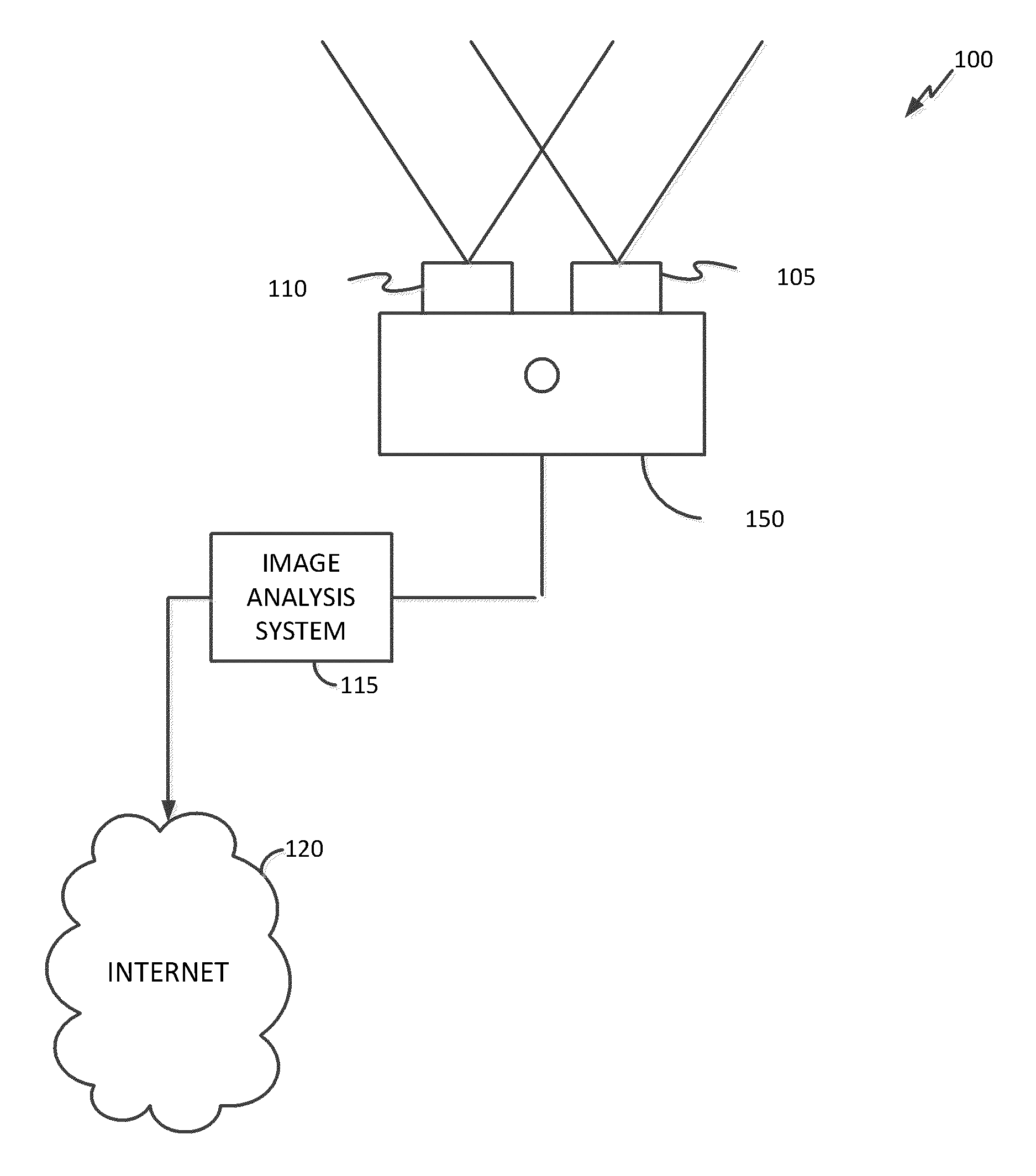
FIG. 1A illustrates a schematic of a stereoscopic imaging system and apparatus.
FIG. 1B illustrates a schematic of an imaging sensor pair mounted as part of an imaging device.
FIG. 1C illustrates a schematic of an imaging sensor pair in which one imaging sensor has rotated about the yaw axis such by an angle A.
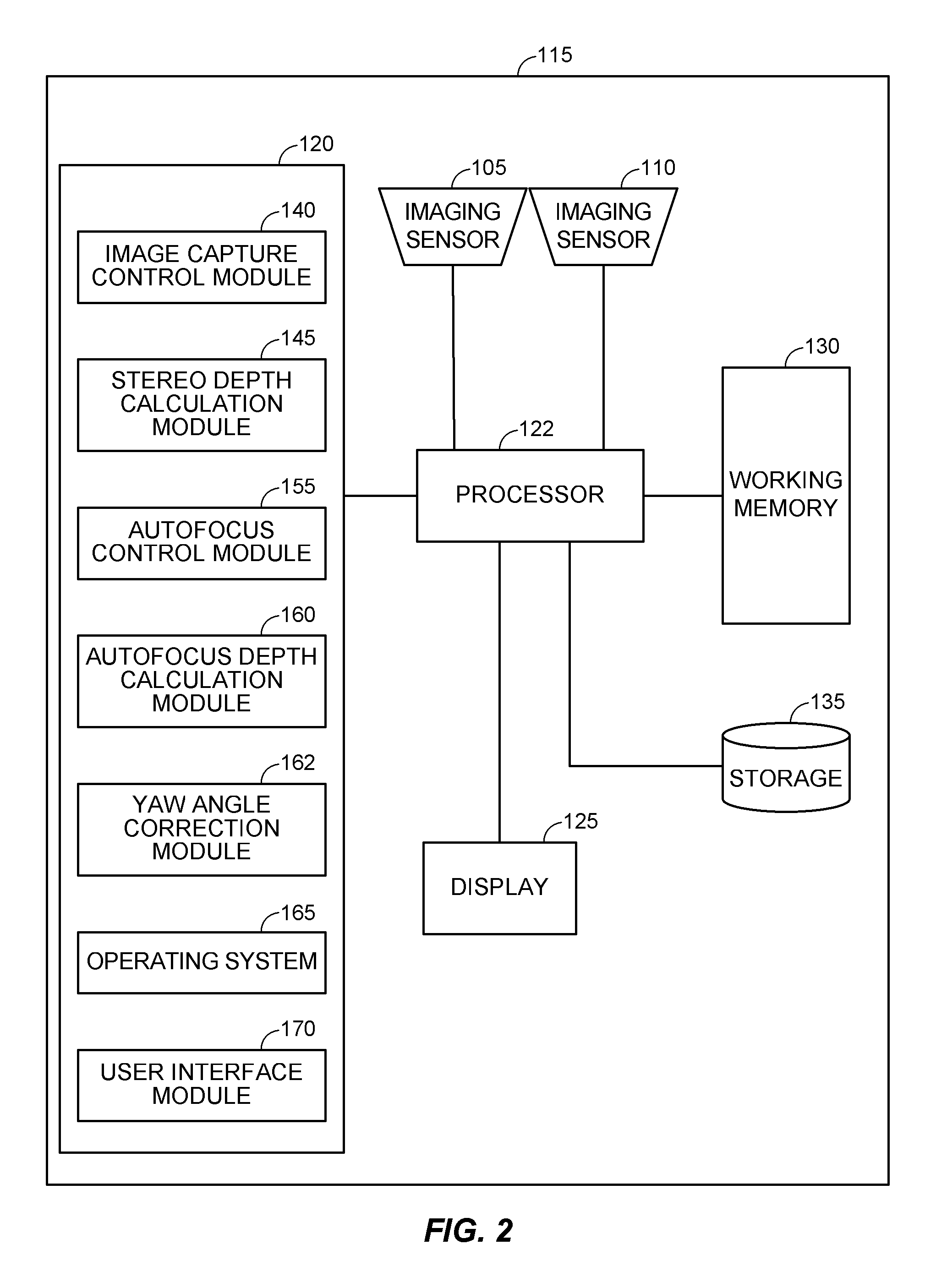
FIG. 2 is a block diagram depicting a system implementing some operative elements of digital correction of yaw misalignment of imaging sensors.
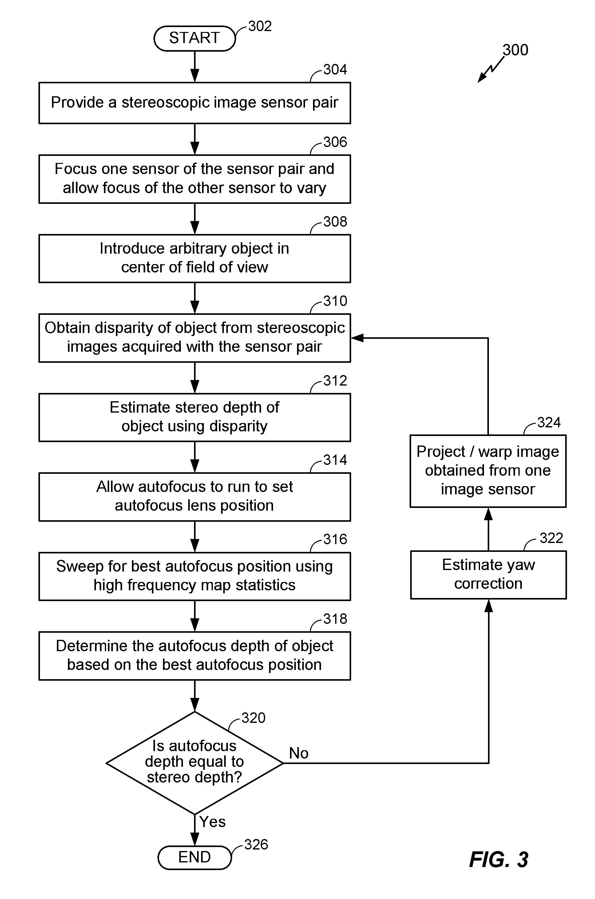
FIG. 3 is a flow chart depicting a high-level overview of a process to correct yaw misalignment of imaging sensors according to one embodiment.
FIG. 4 illustrates a graph of a disparity drift due to yaw for a planar object viewed by stereoscopic imaging sensors at a fixed depth.
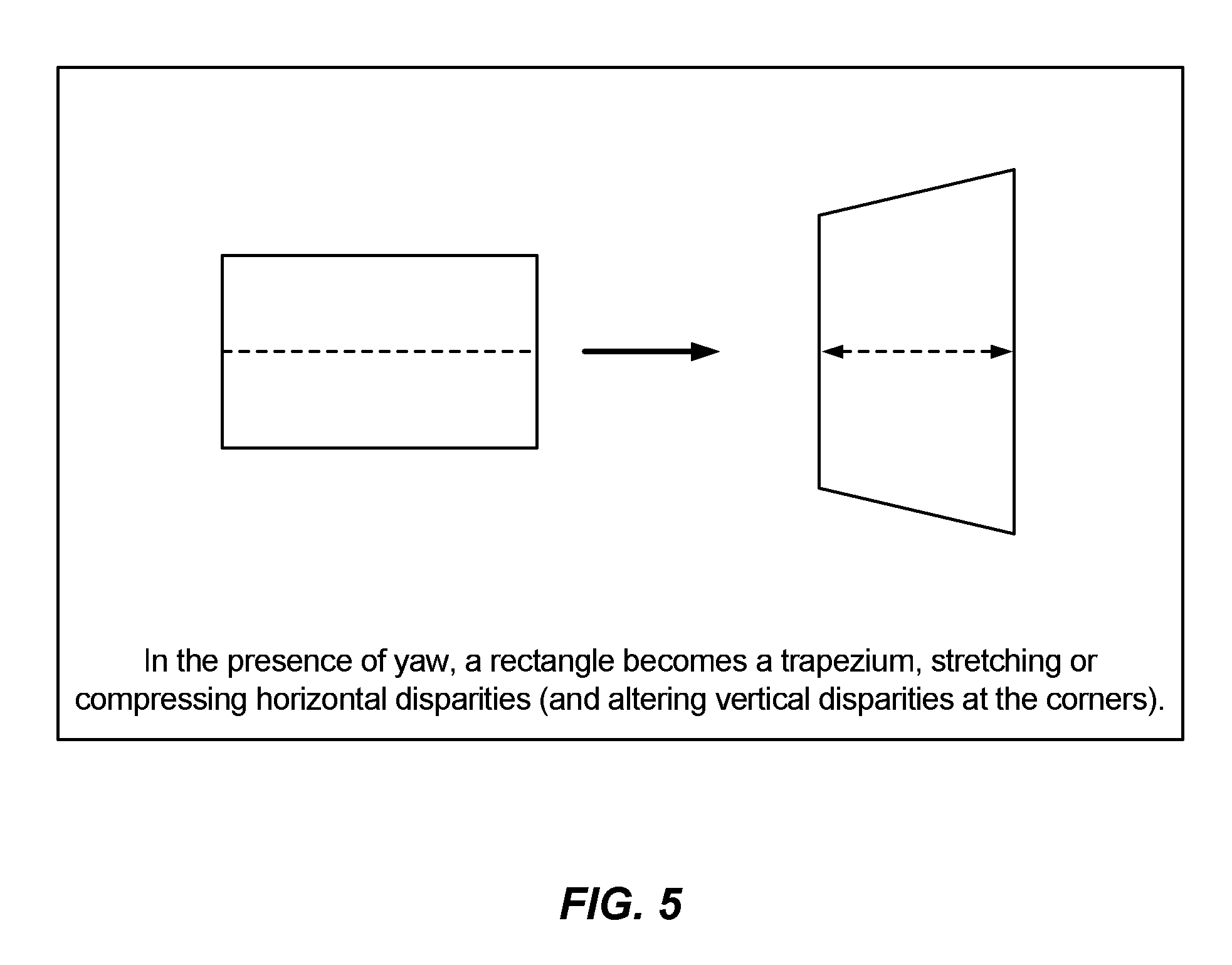
FIG. 5 illustrates the horizontal and vertical disparity of a rectangle viewed with stereoscopic imaging sensors misaligned in the yaw direction.
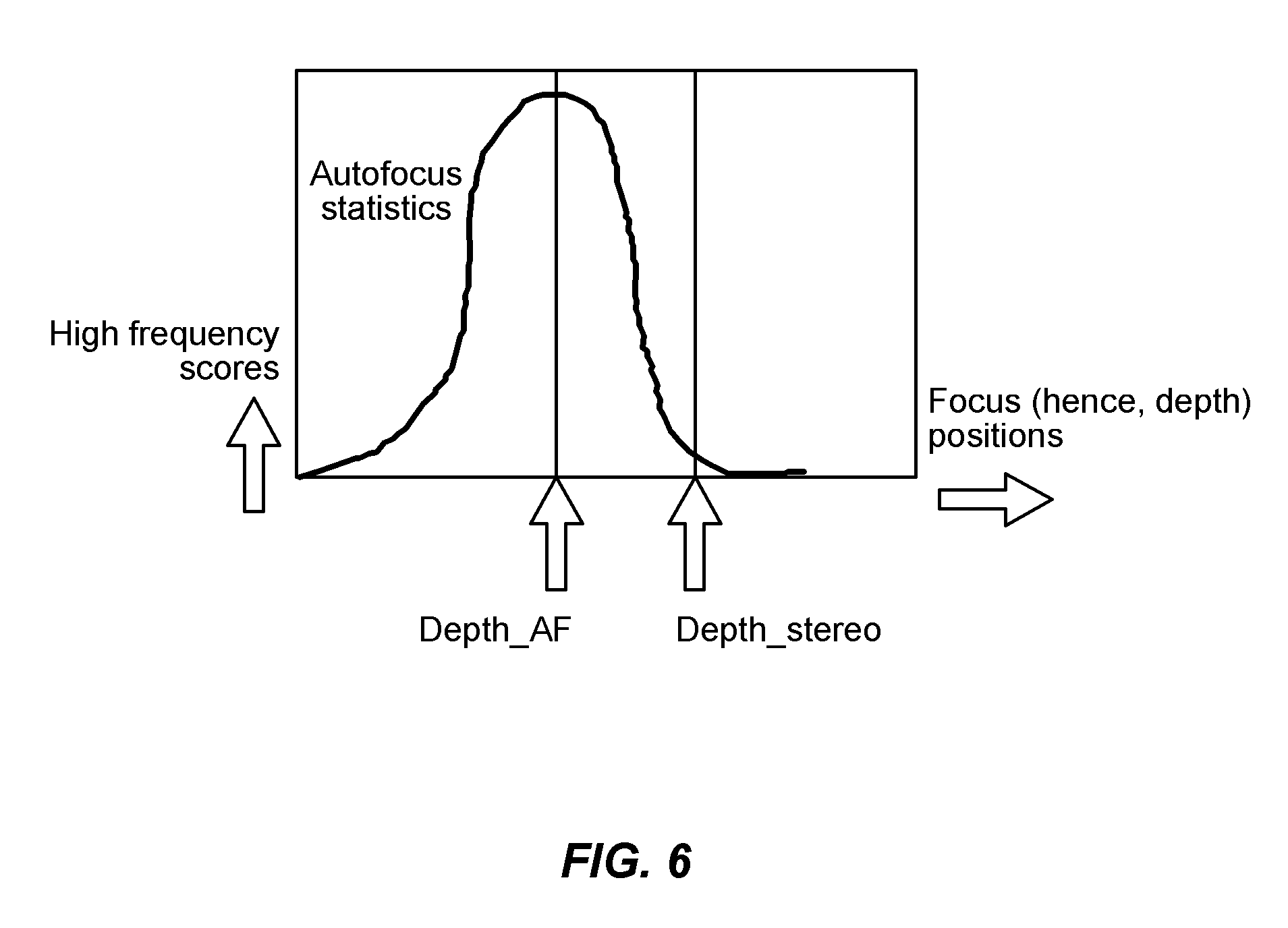
FIG. 6 graphically illustrates the difference between the autofocus depth position and the stereoscopic depth position for imaging sensors having yaw misalignment.
FIG. 7 is a flow chart depicting a high-level overview of a process to correct autofocus lens position of stereoscopic imaging sensors according to another embodiment.
DESCRIPTION OF CERTAIN INVENTIVE ASPECTS
Certain visual experiments indicate that in order to see a three-dimensional (3D) presentation based on stereoscopic imagery (sometimes referred to herein as "stereo images," "stereoscopic images" or "stereoscopic image pairs") with minimal discomfort or strain, the "left" and "right" digital sensors that are used to capture the stereo images should be properly aligned with one another. For example, the optical (or sensing) axis of the two digital sensors may be optically aligned to be parallel, or substantially parallel, e.g., they differ only by known or easily determined horizontal or vertical shifts which are more easily corrected by digital editing of the captured image. For desirable stereoscopic effects and fusibility of images, a horizontal distance between imaging sensors in a stereoscopic sensor pair is, in some examples, around 3.25 cm. In addition, there is preferably only a relatively small horizontal or vertical shift between the sensors in the pair. However, in actual practice, obtaining aligned parallel imaging sensors is often unachievable due to mechanical mounting limitations, alignment measuring devices, gravity and/or heat effects on the sensors. Thus, certain embodiments described herein provide systems and methods for correcting depth measurement errors of stereoscopic imaging sensors due primarily to sensor drift in the yaw direction.
Calibration of stereoscopic images through digital image processing may be required to align the pairs of images after they have been captured. Some methods may digitally process the stereoscopic image pairs to produce aligned images. Aligning stereoscopic images may include, for example, cropping one or both images to correct for horizontal (x axis) or vertical (y axis) shift between the images of a stereoscopic image pair. The two images of a stereoscopic image pair may also be misaligned about a "z" axis, caused when one imaging sensor is slightly closer to a scene being imaged than the other imaging sensor. Cropping may also be required to correct for misalignment due to rotation of the images about an x, y, or z axis. Finally, cropping may also be required to adjust the convergence point of the two images in the stereoscopic image pair.
In addition to the two dimensional x, y and z offsets discussed above, the relative positions of a pair of imaging sensors can also be described by measuring three axes of angular movement and three axes of shift. For purposes of this disclosure, positions on an x, y, and z axis describe relative shift. Angular rotation can be described by rotations about a horizontal (x) axis, also called "pitch," vertical (y) axis, known as "roll," and (z) axis or "yaw."
Some configurations of stereoscopic cameras may have asymmetric sensors wherein one sensor is a low resolution image sensor and the other sensor is a high resolution image sensor. During manufacture, the sensors are calibrated such that the sensor images are parallel. However, for some configurations, such as cameras with high quality autofocus systems, the camera lens positions slowly drift due to gravity, heat, mechanical assembly issues, or wear and tear. Lens position drift in the yaw position in particular can cause depth measurement errors. In some configurations, estimation of the yaw angle difference between the two imaging sensors may be used to correct the depth measurements.
For other configurations, such as cameras with low quality autofocus system, the autofocus accuracy can drift over time due to wear and tear of the components or aging materials used to form the components. In some configurations, a distance or depth measurement of objects in a scene that is estimated using stereo imaging sensors is better than an autofocus depth estimate determined by using the autofocus system in the device. Therefore, in some configurations, the depth estimated using the stereo imaging sensors may be used to correct the autofocus lens position. Special charts or targets may not be needed to correct the depth error measurement and adjust the autofocus lens position of the imaging sensors. In many cases, no user input is needed to perform the correction. Furthermore, image processing of the stereo images such as keypoint detection and matching may not be needed in some embodiments. Additionally, since the autofocus search space is generally small and the yaw drift is generally small, the processes described below are quick and work in real time.
System Overview
FIG. 1A illustrates a schematic of an embodiment of a system 100 that may be used to correct a depth error measurement performed by an imaging device 150. The illustrated system 100 includes an imaging device 150 that includes two imaging sensors 105 and 110. The two imagine sensors 110 and 105 may be referred to herein as a "pair" of sensors, or a "left" and "right" sensor. The imaging sensors 105 and 110 may be any type of sensor that can capture light and convert the light into electrical signals. In some configurations, the imaging sensors 105 and 110 may be charge-coupled devices (CCD) or CMOS sensors. In the embodiment illustrated, the imaging sensors 105 and 110 are as mounted adjacent one another on the imaging device 150 such that they can capture a stereoscopic image of an object (or scene). The imaging sensors 110 and 105 may be configured to capture images of the same resolution, or different resolutions.
FIG. 1A also illustrates an image analysis system 115 coupled to the imaging device 150 and in data communication with the imaging device 150. One example of an image analysis system 115 is further described with reference to FIG. 2. In some implementations, the image analysis system 115 may be housed together with the imaging device 150, while in others the imaging device 150 and the image analysis system 115 are housed separately. For example, the image analysis system 115 may be incorporated into the imaging device 150 or may be a separate system. The image analysis system 115 may be configured, and be operable to, determine the relative positions of the imaging sensors 105 and 110 mounted on the imaging device 150 and determine and/or provide image correction information, for example, depth measurement error corrections and correction of horizontal and vertical disparities caused by disparity drift of the imaging sensors 105 and 110 due to yaw. In some embodiments, the image analysis system is coupled to the imaging device for communicating information between the image analysis system and the imaging device. The coupling may be, for example, via a wired or wireless connection.
FIGS. 1B and 1C illustrate the imaging sensors 105 and 110 mounted as part of the imaging device 150. FIG. 1B illustrates a yaw angle rotation of the sensor 105 about a yaw axis. FIG. 1C illustrates the imaging sensor 105 that has experienced yaw angle drift (as indicated by angle A) and is therefore facing in a slightly different direction than the imaging sensor 110. Angle A illustrates a yaw angle disparity between the imaging sensor 110 and the imaging sensor 105. FIGS. 1B and 1C illustrate a set of imaging sensors 105 and 110 placed side by side. However, the imaging sensors 105 and 110 may be in any orientation, including side to side, top to bottom, or diagonal. Additionally, one imaging sensor 105 is shown to have a yaw disparity from the imaging sensor 110 as indicated by angle A. In other embodiments, imaging sensor 110 may have a yaw disparity from the imaging sensor 105.
FIG. 2 illustrates a block diagram of one embodiment of an image analysis system 115 having a set of components including a processor 122 in communication with imaging sensors 105 and 110. The image analysis system 115 may include additional components, for example, that are not shown in FIG. 2 for clarity of the illustrated components. The image analysis system 115 also includes a working memory 130, storage 135, electronic display 125, and memory 120 that are also in communication with processor 122.
Image analysis system 115 may be a stationary device such as a desktop personal computer or it may be a mobile device. A plurality of applications may be available to the user on image analysis system 115. These applications may include traditional photographic applications, high dynamic range imaging, panoramic video, or stereoscopic imaging such as 3D images or 3D video.
Processor 122 may be a general purpose processing unit or a processor specially designed for imaging applications. As shown, the processor 122 is connected to a memory 120 and a working memory 130. In the illustrated embodiment, the memory 120 stores several modules, including an image capture control module 140, a stereo depth calculation module 145, an autofocus control module 155, an autofocus depth calculation module 160, a yaw angle correction module 162, operating system 165, and user interface module 170. These modules may include instructions that configure the processor 122 to perform various image processing and device management tasks. Working memory 130 may be used by processor 122 to store a working set of processor instructions contained in the modules of memory 120. Alternatively, working memory 130 may also be used by processor 122 to store dynamic data created during the operation of image analysis system 115.
Still referring to FIG. 2, as mentioned above, the processor 122 may be configured by several modules stored in the memory 120. Image capture control module 140 may include instructions that configure the processor 122 to control imaging sensors 105 and 110 to capture images of a scene. Therefore, processor 122, along with image capture control module 140, imaging sensors 105 or 110, and working memory 130, represent one means for capturing one or more images of an object with a pair of stereoscopic image sensors. The stereo depth calculation module 145 provides instructions that configure the processor 122 to determine a disparity of an object within two or more of captured images of the object and estimate the stereo or stereoscopic depth of the object, defined as the distance of the object from the sensors as determined geometrically from the image data acquired by the pair of image sensors 105, 110. Therefore, processor 122, along with stereo depth calculation module 145 and working memory 130, represent one example of an embodiment of means for estimating the stereoscopic depth of an object from one or more images acquired by a stereoscopic image sensor pair 105 and 110.
The autofocus control module 155 provides instructions that configure the processor 122 to perform an autofocus function using the image sensors 105, 110 to, for example, search for the best high frequency map of the image scene. The autofocus depth calculation module 160 provides instructions that configure the process 122 to calculate a depth of an object in a scene based on one or more characteristics of an autofocus system, for example, the positions of each of the image sensors 105, 110 when the object is determined to be in focus using autofocus functionality. For example, based on the autofocus position of the image sensors 105, 110 during the autofocus function, an equivalent "true" depth or equivalent estimated depth of an object in a scene may be determined. The autofocus characteristic may be, for example, a physical or optical position of one or more components of each of, or one of, the imaging sensors 105, 110 positioned during autofocus operation. The autofocus position may be based on, for example, determining a position of the imaging sensors 105 and 110 to focus on the object using high frequency information (for example, noise) of the object or the scene. Therefore, processor 122, along with autofocus control module 155, autofocus depth calculation module 160, and working memory 130 represent one example of an embodiment of means for performing an autofocus function on the object to determine an autofocus characteristic (for example, position of the imaging sensors) and estimating an autofocus depth of an object from the high frequency autofocus position.
The yaw angle correction module 162 provides instructions that configure the processor 122 to calculate a difference between the depth as measured by the autofocus function and the "depth" of an object in a scene based on the disparity of an object as indicated by the stereoscopic images acquired by the stereoscopic imaging sensors 105 and 110. This difference may used by the yaw angle correction module 162 to estimate and correct the yaw angle of the stereoscopic imaging sensors 105 and 110. Therefore, processor 122, along with yaw angle correction module 162 and working memory 130 represent one example of an embodiment of means for estimating and correcting a yaw angle correction using the difference between the autofocus depth and the stereoscopic depth.
User interface module 170 can include instructions that configure the processor 122 to display information on an electronic display accessible to the user while running the image analysis system 115. Operating system module 165 may configure the processor 122 to manage the memory and processing resources of system 115. For example, operating system module 165 may include device drivers to manage hardware resources such as the electronic display 125 or imaging sensors 105 and 110. In some embodiments, instructions contained in the image processing modules discussed above may not interact with these hardware resources directly, but instead may interact through standard subroutines or APIs located in operating system component 165. Instructions within operating system 165 may then interact directly with these hardware components.
Processor 122 may write data to storage module 130. While storage module 130 is represented graphically as a traditional disk drive, those with skill in the art would understand multiple embodiments could include either a disk-based storage device or one of several other types of storage mediums, including a memory disk, USB drive, flash drive, remotely connected storage medium, virtual disk driver, or the like.
Although FIG. 2 depicts an example embodiment of a device having separate components to include a processor, two imaging sensors, electronic display, and memory, one skilled in the art would recognize that these separate components may be combined in a variety of ways to achieve particular design objectives. For example, in an alternative embodiment, the memory components may be combined with processor components to save cost and improve performance.
Additionally, although FIG. 2 illustrates two memory components, including memory component 120 comprising several modules and a separate memory 130 comprising a working memory, one with skill in the art would recognize several embodiments utilizing different memory architectures may be implemented in various embodiments. For example, a design may utilize ROM or static RAM memory for the storage of processor instructions implementing the modules contained in memory 120. In some embodiments, processor instructions may be read at system startup from a disk storage device that is integrated into image analysis system 115 or connected via an external device port. The processor instructions may then be loaded into RAM to facilitate execution by the processor. For example, working memory 130 may be a RAM memory, with instructions loaded into working memory 130 before execution by the processor 122.
Method Overview
Embodiments of the invention relate to methods for correcting depth measurement disparity due to misalignment of stereoscopic imaging sensors, for example, imaging sensors 105 and 110, as described above with reference to FIGS. 1B and 1C. Two embodiments of methods incorporating autofocus feedback are discussed below. Selection of a method may be influenced by the quality of the autofocus system of the electronic device. For example, for devices with a high quality autofocus system, lens positions of the imaging device 150 can drift slowly due to gravity and heat effects, as well as mechanical assembly inaccuracies and in-use wear and tear. The yaw angle can therefore be estimated using the high quality autofocus system. In another example, for devices with low quality autofocus systems, the autofocus accuracy of the device may start to drift with age. The depth estimated using stereo imaging is therefore likely better than the autofocus depth estimate and thus, the stereo imaging depth can be used to correct the autofocus lens position of the imaging device 150.
FIG. 3 illustrates one embodiment of a process 300 to correct stereo yaw that may be implemented in several modules depicted in FIG. 2. Various embodiments may include additional actions not depicted in FIG. 3, and/or just some of actions illustrated in FIG. 3. Process 300 may be used in some embodiments to estimate and correct a yaw angle alignment of a stereoscopic image pair for a device having a high quality autofocus system. In some examples, the process 300 may be run on a processor, for example, processor 122 (FIG. 2), and on other components illustrated in FIG. 2 that are stored in memory 120 or that are incorporated in other hardware or software. The process 300 begins at start block 302 and transitions to block 304 wherein a stereoscopic image sensor pair is provided. The image sensor pair may be provided, for example, in a camera, incorporated in a handheld communication device, e.g., a cellular phone or "smartphone," or a mobile personal data assistant (PDA) including a tablet computer.
The process 300 then transitions to block 306 wherein the focus of one imaging sensor is fixed (such as imaging sensor 105 shown in FIG. 2) and the other imaging sensor focus is allowed to vary as needed (such as imaging sensor 110 shown in FIG. 2). However, in other embodiments, the focus of imaging sensor 110 may be fixed and the focus of the other imaging sensor 105 may vary as needed. The focus of either imaging sensor 105 or 110 could be fixed or moving. The process 300 then transitions to block 308, wherein an object is introduced in the center of the field of view of the imaging sensors 105, 110 with center focus enabled. The process 300 next transitions to block 310, wherein the disparity of the object is found from the image data acquired by the imaging sensors 105, 110. In some embodiments, the disparity may be found by determining one or more keypoints of the object and matching the keypoint locations in the images acquired by each sensor of the imaging sensor pair. Keypoints may be distinctive regions of an object that exhibit particularly unique characteristics. For example, regions that exhibit particular patterns or edges may be defined as keypoints. A keypoint match may include a pair of points, with one point identified in the first image and the second point identified in the second image.
One example of a disparity drift due to yaw is shown graphically in FIG. 4. The x-axis of FIG. 4 illustrates a fraction of the field of view of the image sensors 105 and 110. The y-axis of FIG. 4 illustrates the yaw disparity angle A. When viewing a planar object with aligned image sensors 105 and 110, the planar object should appear as a single straight line, such as line 410. In other words, the disparity should be constant if the planar object is straight to the camera and the image sensor 105 and 110 are aligned. If there is some disparity angle A between image sensors 105 and 110, the planar object should appear as a curved line, such as line 405. The line 405 represents the disparity drift of a planar object at a fixed depth with the yaw angle equal to 11 degrees. The line 410 illustrates the expected constant disparity with no yaw angle difference between the two imaging sensors. A disparity drift between the image sensors may cause discomfort for a user viewing the images.
FIG. 5 illustrates the resulting stereoscopic image when a yaw disparity exists between two imaging sensors. In the presence of yaw angle disparity, a rectangle becomes a trapezium, stretching or compressing the horizontal disparities and altering vertical disparities at the corners.
After determining the disparity of the object between the images acquired by each sensor of the imaging sensor pair such as imaging sensors 105, 110, the process 300 transitions to block 312, wherein the stereo depth of the object is estimated using the disparity. In some embodiments, the stereo depth may be calculated as follows: Depth_stereo=baseline*focal length/disparity, where baseline is the distance between the two imaging sensors of the stereoscopic imaging sensor pair.
Referring again to FIG. 3, after determining the stereo depth of the object, the process 300 transitions to block 314, wherein the processor 122 instructs the autofocus feature of the imaging device 150 to run to set an autofocus lens position of the imaging sensors 105, 110. The process 300 then transitions to block 316, wherein the processor 122 instructs the imaging device 150 to sweep through autofocus positions to determine a position (or setting) of one or more of the imaging sensors 105, 110 that produces, for example, the maximum high frequency map. The process 300 then transitions to block 318, wherein an autofocus "depth" of an object, as calculated by the autofocus feature, may be found using autofocus information (for example, statistic(s) calculated during the autofocus process).
One example of the autofocus statistics is shown in FIG. 6. The focus position having the highest frequency autofocus scores, as indicated by the y-axis of the graph shown in FIG. 6, indicates the position where the image is the sharpest. To determine the autofocus depth position having the highest frequency scores, the autofocus function is directed to sweep over the different focus values. Using a sharpness detector, a sharpness of the image is indicated and the autofocus statistics will indicate at what autofocus position the image is sharpest. Based on the best autofocus position as indicated by the maximum number of high frequency scores, the equivalent "true" depth or autofocus depth (Depth_AF) of the object is found.
In the next block 320 of the process 300 illustrated in FIG. 3, the Depth_AF of the object is compared to the Depth_stereo of the object. If the two depths are not equal, then a yaw angle disparity is present and the process 300 transitions to block 322 wherein the yaw angle correction is estimated. The process 300 next transitions to block 324, wherein the image acquired by one sensor of the imaging sensors 105, 110 is projected or warped based on the estimated yaw angle difference between the two imaging sensors 105, 110 to correct for the yaw angle difference. The process 300 repeats beginning at block 310 by determining the disparity and estimating the depth of the object until the Depth_AF of the object as calculated by the autofocus statistics and the Depth_stereo of the object are equal. When the autofocus depth and the stereo depth of the object are equal, the yaw disparity has been corrected and the process 300 transitions to block 326 and ends.
In another embodiment that may be particularly useful for imaging devices having poor or low quality autofocus systems, the autofocus accuracy may drift with age. In some embodiments, the estimated depth measurement to an object in an imaged scene is more accurate using stereo depth estimation rather than autofocus depth estimations. In these embodiments, the stereo depth measurement may be used to correct the autofocus lens position of the imaging device 150. One embodiment of a process to correct autofocus lens position using estimated stereo depth measurements is shown in FIG. 7.
FIG. 7 illustrates one embodiment of a process 700 to correct an autofocus lens position as that may be implemented in several modules depicted in FIG. 2. Process 700 may be used in some embodiments to estimate and correct an autofocus position of an imaging device with a low quality autofocus system having a stereoscopic imaging sensor pair. In some examples, the process 700 may be run on a processor, for example, processor 122 (FIG. 2), and on other components illustrated in FIG. 2 that are stored in memory 120 or that are incorporated in other hardware or software. The process 700 begins at start block 702 and transitions to block 704, wherein an imaging device such as imaging device 150 having an imaging sensor pair 105, 110 is provided. The process 700 then transitions to block 706, wherein the focus of one imaging sensor 105, 110 is fixed and the other imaging sensor focus is allowed to vary. The focus of either imaging sensor 105 or 110 could be fixed or moving. The process 700 then transitions to block 708, wherein an object is introduced in the center of the field of view of the imaging sensor 105, 110 with center focus enabled. The process 700 next transitions to block 710, wherein the disparity of the object is found from the image data acquired by the imaging sensor pair. In some embodiments, the disparity may be found by determining one or more keypoints of the object and matching the keypoint locations in the image data acquired by each sensor of the imaging sensor pair. Keypoints may be distinctive regions of an object that exhibit particularly unique characteristics. For example, regions that exhibit particular patterns or edges may be defined as keypoints. A keypoint match may include a pair of points, with one point identified in the first image and the second point identified in the second image.
After determining the disparity of the object between the image data acquired by each sensor of the imaging sensor pair, the process 700 transitions to block 712, wherein the stereo depth of the object is estimated using the disparity. In some embodiments, the stereo depth may be calculated as follows: Depth_stereo=baseline*focal length/disparity, where baseline is the distance between the two imaging sensors of the stereoscopic imaging sensor pair.
After determining the stereo depth of the object, the process 700 transitions to block 714, where the autofocus feature of the imaging device maybe activated to determine the autofocus lens position. The process 700 then transitions to block 716, wherein the imaging device may sweep through two or more autofocus positions of the imaging sensors to search for the best high frequency map. The process 700 then transitions to block 718, wherein an autofocus depth of an object, as calculated by the autofocus feature, may be found from the autofocus statistics. As discussed above, one example of the autofocus statistics is shown in FIG. 6. Based on the best autofocus position as indicated by the maximum number of high frequency scores, the equivalent "true" depth or Depth_AF of the object is found.
In the next block 720 of the process 700 shown in FIG. 7, the Depth_AF is compared to the Depth_stereo. If the two depths are not equal, the autofocus lens position may be corrected and the process 700 transitions to block 714 where the process 700 continues by setting a new autofocus position of the imaging sensors and the process 700 repeats until the Depth_AF of the object as calculated using the best autofocus position as determined by the autofocus statistics and the Depth_stereo of the object calculated from the disparity between the image data of the imaging sensors is equal. When the autofocus depth and the stereo depth are equal (or substantially equal), the process 700 transitions to block 726 and ends.
Clarifications Regarding Terminology
Unless expressly limited by its context, the term "signal" is used herein to indicate any of its ordinary meanings, including a state of a memory location (or set of memory locations) as expressed on a wire, bus, or other transmission medium. Unless expressly limited by its context, the term "generating" is used herein to indicate any of its ordinary meanings, such as computing or otherwise producing. Unless expressly limited by its context, the term "calculating" is used herein to indicate any of its ordinary meanings, such as computing, evaluating, smoothing, and/or selecting from a plurality of values. Unless expressly limited by its context, the term "obtaining" is used to indicate any of its ordinary meanings, such as calculating, deriving, receiving (e.g., from an external device), and/or retrieving (e.g., from an array of storage elements). Unless expressly limited by its context, the term "selecting" is used to indicate any of its ordinary meanings, such as identifying, indicating, applying, and/or using at least one, and fewer than all, of a set of two or more. Where the term "comprising" is used in the present description and claims, it does not exclude other elements or operations. The term "based on" (as in "A is based on B") is used to indicate any of its ordinary meanings, including the cases (i) "derived from" (e.g., "B is a precursor of A"), (ii) "based on at least" (e.g., "A is based on at least B") and, if appropriate in the particular context, (iii) "equal to" (e.g., "A is equal to B"). Similarly, the term "in response to" is used to indicate any of its ordinary meanings, including "in response to at least."
Unless indicated otherwise, any disclosure of an operation of an apparatus having a particular feature is also expressly intended to disclose a method having an analogous feature (and vice versa), and any disclosure of an operation of an apparatus according to a particular configuration is also expressly intended to disclose a method according to an analogous configuration (and vice versa). The term "configuration" may be used in reference to a method, apparatus, and/or system as indicated by its particular context. The terms "method," "process," "procedure," and "technique" are used generically and interchangeably unless otherwise indicated by the particular context. The terms "apparatus" and "device" are also used generically and interchangeably unless otherwise indicated by the particular context. The terms "element" and "module" are typically used to indicate a portion of a greater configuration. Unless expressly limited by its context, the term "system" is used herein to indicate any of its ordinary meanings, including "a group of elements that interact to serve a common purpose." Any incorporation by reference of a portion of a document shall also be understood to incorporate definitions of terms or variables that are referenced within the portion, where such definitions appear elsewhere in the document, as well as any figures referenced in the incorporated portion.
Those having skill in the art will further appreciate that the various illustrative logical blocks, modules, circuits, and process steps described in connection with the implementations disclosed herein may be implemented as electronic hardware, computer software, or combinations of both. To clearly illustrate this interchangeability of hardware and software, various illustrative components, blocks, modules, circuits, and steps have been described above generally in terms of their functionality. Whether such functionality is implemented as hardware or software depends upon the particular application and design constraints imposed on the overall system. Skilled artisans may implement the described functionality in varying ways for each particular application, but such implementation decisions should not be interpreted as causing a departure from the scope of the present invention. One skilled in the art will recognize that a portion, or a part, may comprise something less than, or equal to, a whole. For example, a portion of a collection of pixels may refer to a sub-collection of those pixels.
The various illustrative logical blocks, modules, and circuits described in connection with the implementations disclosed herein may be implemented or performed with a general purpose processor, a digital signal processor (DSP), an application specific integrated circuit (ASIC), a field programmable gate array (FPGA) or other programmable logic device, discrete gate or transistor logic, discrete hardware components, or any combination thereof designed to perform the functions described herein. A general purpose processor may be a microprocessor, but in the alternative, the processor may be any conventional processor, controller, microcontroller, or state machine. A processor may also be implemented as a combination of computing devices, e.g., a combination of a DSP and a microprocessor, a plurality of microprocessors, one or more microprocessors in conjunction with a DSP core, or any other such configuration.
The steps of a method or process described in connection with the implementations disclosed herein may be embodied directly in hardware, in a software module executed by a processor, or in a combination of the two. A software module may reside in RAM memory, flash memory, ROM memory, EPROM memory, EEPROM memory, registers, hard disk, a removable disk, a CD-ROM, or any other form of non-transitory storage medium known in the art. An exemplary computer-readable storage medium is coupled to the processor such the processor can read information from, and write information to, the computer-readable storage medium. In the alternative, the storage medium may be integral to the processor. The processor and the storage medium may reside in an ASIC. The ASIC may reside in a user terminal, camera, or other device. In the alternative, the processor and the storage medium may reside as discrete components in a user terminal, camera, or other device.
Headings are included herein for reference and to aid in locating various sections. These headings are not intended to limit the scope of the concepts described with respect thereto. Such concepts may have applicability throughout the entire specification.
The previous description of the disclosed implementations is provided to enable any person skilled in the art to make or use the present invention. Various modifications to these implementations will be readily apparent to those skilled in the art, and the generic principles defined herein may be applied to other implementations without departing from the spirit or scope of the invention. Thus, the present invention is not intended to be limited to the implementations shown herein but is to be accorded the widest scope consistent with the principles and novel features disclosed herein.
* * * * *
References
D00000
D00001
D00002
D00003
D00004
D00005
D00006
D00007
D00008
XML
uspto.report is an independent third-party trademark research tool that is not affiliated, endorsed, or sponsored by the United States Patent and Trademark Office (USPTO) or any other governmental organization. The information provided by uspto.report is based on publicly available data at the time of writing and is intended for informational purposes only.
While we strive to provide accurate and up-to-date information, we do not guarantee the accuracy, completeness, reliability, or suitability of the information displayed on this site. The use of this site is at your own risk. Any reliance you place on such information is therefore strictly at your own risk.
All official trademark data, including owner information, should be verified by visiting the official USPTO website at www.uspto.gov. This site is not intended to replace professional legal advice and should not be used as a substitute for consulting with a legal professional who is knowledgeable about trademark law.