Shopping cart bagging station
Bacallao J
U.S. patent number 10,173,708 [Application Number 16/053,248] was granted by the patent office on 2019-01-08 for shopping cart bagging station. This patent grant is currently assigned to WALMART APOLLO, LLC. The grantee listed for this patent is Walmart Apollo, LLC. Invention is credited to Yurgis Mauro Bacallao.


View All Diagrams
| United States Patent | 10,173,708 |
| Bacallao | January 8, 2019 |
Shopping cart bagging station
Abstract
Described is a shopping cart bagging station can be used by customers to bag their purchases as they shop. The disclosed shopping cart bagging station includes a box front portion and a back plate that couple together to form a rectangular enclosure for shopping bags. The box front portion has a bag holder hook inside the enclosure that shopping bags are hung from. An opening in the box front portion allows access to the shopping bags hanging from the bag holder hook. At least one cart coupling hook is coupled to the back plate to couple the shopping cart bagging station to a shopping cart. A customer hangs the shopping cart bagging station, with shopping bags hung from the bag holder hook, on the side of a shopping cart, and uses the shopping cart bagging station to provide shopping bags while they shop.
| Inventors: | Bacallao; Yurgis Mauro (Centerton, AR) | ||||||||||
|---|---|---|---|---|---|---|---|---|---|---|---|
| Applicant: |
|
||||||||||
| Assignee: | WALMART APOLLO, LLC
(Bentonville, AR) |
||||||||||
| Family ID: | 64872686 | ||||||||||
| Appl. No.: | 16/053,248 | ||||||||||
| Filed: | August 2, 2018 |
Related U.S. Patent Documents
| Application Number | Filing Date | Patent Number | Issue Date | ||
|---|---|---|---|---|---|
| 62546850 | Aug 17, 2017 | ||||
| Current U.S. Class: | 1/1 |
| Current CPC Class: | B62B 3/146 (20130101); B62B 3/1464 (20130101); B62B 3/1472 (20130101); B62B 2202/26 (20130101) |
| Current International Class: | B62B 3/14 (20060101) |
| Field of Search: | ;224/411,925 ;248/690,692,95 |
References Cited [Referenced By]
U.S. Patent Documents
| 259932 | June 1882 | Sims |
| 370563 | September 1887 | Simmons |
| 562229 | June 1896 | Lenney |
| 635100 | October 1899 | Huebel |
| 765388 | July 1904 | Lanpher |
| 797871 | August 1905 | Smith |
| 809568 | January 1906 | Hulburt |
| 873188 | December 1907 | Thumann |
| 890693 | June 1908 | McCoy |
| 893930 | July 1908 | Lederman |
| 896443 | August 1908 | Dyett |
| 936736 | October 1909 | Porter et al. |
| 995798 | June 1911 | McCullough |
| 1055745 | March 1913 | Harrison |
| 1069108 | August 1913 | Buhl |
| 1252740 | January 1918 | Thornblade |
| 1284579 | November 1918 | Brown |
| 1662140 | March 1928 | Whitesides |
| 2240629 | May 1941 | Smith |
| 2498446 | February 1950 | Pawsat |
| 2563679 | August 1951 | Hardy |
| 2603438 | July 1952 | Adams |
| 2682956 | July 1954 | Pike |
| 2797058 | June 1957 | Packham |
| 3133660 | May 1964 | Roberts |
| 3266742 | August 1966 | Pena |
| 3313504 | April 1967 | Thorkild |
| 3339745 | September 1967 | Sugerman |
| D209279 | November 1967 | Cohen |
| 3438644 | April 1969 | Kaplan et al. |
| 3475067 | October 1969 | Girard |
| 3747298 | July 1973 | Lieberman |
| 3930696 | January 1976 | Hight et al. |
| 3943859 | March 1976 | Boone |
| 3995803 | December 1976 | Uitz |
| 4048754 | September 1977 | Laux |
| 4082939 | April 1978 | Walters |
| 4106617 | August 1978 | Boone |
| 4269336 | May 1981 | Humlong |
| 4305558 | December 1981 | Baker |
| 4354643 | October 1982 | Kenner |
| 4367819 | January 1983 | Lewis |
| 4376502 | March 1983 | Cohen |
| 4403807 | September 1983 | Wilkinson et al. |
| 4456125 | June 1984 | Chap |
| 4583753 | April 1986 | Economy |
| 4595153 | June 1986 | Goetz |
| 4655409 | April 1987 | Zima |
| 4682782 | July 1987 | Mills |
| 4702402 | October 1987 | Ferri |
| 4728070 | March 1988 | Engelbrecht |
| 4838504 | June 1989 | Bittenbinder |
| D302062 | July 1989 | Sable |
| 4881577 | November 1989 | Stroh et al. |
| 4968047 | November 1990 | Ferris |
| 4974799 | December 1990 | Palmer |
| 4997149 | March 1991 | Koch |
| 4998647 | March 1991 | Sharp |
| 4998694 | March 1991 | Barteaux |
| 5002215 | March 1991 | Gregoire |
| 5190253 | March 1993 | Sable |
| 5362077 | November 1994 | Adamson |
| 5366123 | November 1994 | Range |
| 5385318 | January 1995 | Rizzuto |
| 5390443 | February 1995 | Emalfarb et al. |
| 5437346 | August 1995 | Dumont |
| 5439120 | August 1995 | Brozak |
| 5443173 | August 1995 | Emery et al. |
| D363208 | October 1995 | Seidel |
| 5460279 | October 1995 | Emery et al. |
| 5465846 | November 1995 | Blyth et al. |
| 5531366 | July 1996 | Strom |
| 5533361 | July 1996 | Halpern |
| 5564566 | October 1996 | Lamb |
| 5618008 | April 1997 | Dearwester et al. |
| 5704497 | January 1998 | Wyatt |
| 5727721 | March 1998 | Guido et al. |
| D396372 | July 1998 | Goodman |
| 5836486 | November 1998 | Ohsugi |
| 5875902 | March 1999 | Emery et al. |
| D412080 | July 1999 | Emery et al. |
| 6018397 | January 2000 | Cloutier et al. |
| 6041945 | March 2000 | Faraj |
| 6086023 | July 2000 | Kerr |
| 6109462 | August 2000 | Emalfarb et al. |
| 6155521 | December 2000 | O'hanlon |
| 6170679 | January 2001 | Frye |
| 6193265 | February 2001 | Yemini |
| 6299001 | October 2001 | Frolov et al. |
| 6305572 | October 2001 | Daniels et al. |
| D452944 | January 2002 | Schmidt |
| 6341704 | January 2002 | Michel, Jr. |
| 6364266 | April 2002 | Garvin |
| 6390422 | May 2002 | Banko |
| 6409031 | June 2002 | Wynne |
| D459979 | July 2002 | Goodman |
| 6481583 | November 2002 | Black et al. |
| 6543638 | April 2003 | Wile |
| 6561403 | May 2003 | Kannankeril et al. |
| 6601759 | August 2003 | Fife et al. |
| 6606411 | August 2003 | Loui et al. |
| 6607229 | August 2003 | McIntosh |
| 6648265 | November 2003 | Goldberg |
| 6655537 | December 2003 | Lang et al. |
| 6685075 | February 2004 | Kannankeril |
| 6726145 | April 2004 | Kraus |
| 6726156 | April 2004 | Scola |
| D490691 | June 2004 | Buss et al. |
| 6745186 | June 2004 | Testa et al. |
| 6789687 | September 2004 | Cramer |
| 6805271 | October 2004 | Holden |
| 6810149 | October 2004 | Squilla et al. |
| 6832739 | December 2004 | Kraus |
| 6886101 | April 2005 | Glazer et al. |
| 6937989 | August 2005 | Mcintyre et al. |
| 7066389 | June 2006 | Dickover et al. |
| 7077612 | July 2006 | Giggle, III et al. |
| 7128251 | October 2006 | Galle |
| 7172092 | February 2007 | Yang et al. |
| 7177820 | February 2007 | Mcintyre et al. |
| 7182210 | February 2007 | Metcalf |
| 7192035 | March 2007 | Lioce |
| D540591 | April 2007 | Snell |
| 7222363 | May 2007 | Rice et al. |
| D552901 | October 2007 | Wilfong, Jr. et al. |
| D571518 | June 2008 | Waldman |
| D575973 | September 2008 | Goodman et al. |
| 7431208 | October 2008 | Feldman et al. |
| 7475885 | January 2009 | Kovath |
| 7530537 | May 2009 | Kandah |
| 7587756 | September 2009 | Peart et al. |
| 7610717 | November 2009 | Luken et al. |
| 7654409 | February 2010 | Hoffman |
| 7716064 | May 2010 | Mcintyre et al. |
| D616680 | June 2010 | Snider |
| 7850014 | December 2010 | Nguyen et al. |
| 7887068 | February 2011 | Ferguson |
| 8069092 | November 2011 | Bryant |
| D650209 | December 2011 | Snider |
| D654737 | February 2012 | Guindi |
| 8177079 | May 2012 | Schwartzkopf et al. |
| D666858 | September 2012 | Goodman |
| D667250 | September 2012 | Goodman et al. |
| 8292094 | October 2012 | Morton |
| 8336800 | December 2012 | Lopez |
| D689282 | September 2013 | Lindeman |
| 8572712 | October 2013 | Rice et al. |
| D693577 | November 2013 | Goodman et al. |
| 8640890 | February 2014 | Schiller |
| 8668207 | March 2014 | Gilliam |
| 8746640 | June 2014 | Broadley et al. |
| 8814039 | August 2014 | Bishop et al. |
| D713663 | September 2014 | Pryor |
| 8820633 | September 2014 | Bishop et al. |
| 8851369 | October 2014 | Bishop et al. |
| D718054 | November 2014 | Goodman et al. |
| D719372 | December 2014 | Goodman et al. |
| 8905411 | December 2014 | Blanton |
| D720538 | January 2015 | Goodman et al. |
| D728255 | May 2015 | Guindi et al. |
| 9199656 | December 2015 | Tong et al. |
| D746592 | January 2016 | Goodman et al. |
| D747876 | January 2016 | Goodman et al. |
| D750472 | March 2016 | Kuka |
| D751763 | March 2016 | Goodman et al. |
| D784721 | April 2017 | Goodman et al. |
| 9623995 | April 2017 | Tan |
| D785333 | May 2017 | Goodman et al. |
| D785369 | May 2017 | Goodman et al. |
| D787303 | May 2017 | Garvin |
| 9656827 | May 2017 | Sudhir |
| 9737141 | August 2017 | Johnson |
| D796771 | September 2017 | Bacallao et al. |
| D803032 | November 2017 | Jammehdiabadi |
| 9844283 | December 2017 | Bacallao |
| 2002/0145086 | October 2002 | Alvarado et al. |
| 2002/0170937 | November 2002 | Yeh et al. |
| 2002/0185510 | December 2002 | Holsclaw |
| 2002/0185513 | December 2002 | Morris |
| 2003/0000905 | January 2003 | Zidek |
| 2003/0042694 | March 2003 | Werner |
| 2003/0052464 | March 2003 | McGuire |
| 2003/0098326 | May 2003 | Wile |
| 2003/0121871 | July 2003 | Zadro |
| 2003/0198390 | October 2003 | Loui et al. |
| 2004/0000529 | January 2004 | Gladnick et al. |
| 2004/0000612 | January 2004 | Young |
| 2004/0075015 | April 2004 | Cain et al. |
| 2004/0124598 | July 2004 | Williams |
| 2004/0139398 | July 2004 | Testa et al. |
| 2004/0178298 | September 2004 | Kennard |
| 2004/0262385 | December 2004 | Blaeuer |
| 2005/0056718 | March 2005 | Kamenstein |
| 2005/0205578 | September 2005 | Yeh |
| 2005/0284729 | December 2005 | LoRusso |
| 2006/0049591 | March 2006 | Pennell |
| 2006/0097467 | May 2006 | Solomon et al. |
| 2006/0124799 | June 2006 | Johnson |
| 2006/0226187 | October 2006 | Linker |
| 2007/0095769 | May 2007 | Jenkins |
| 2007/0176058 | August 2007 | Kohn |
| 2007/0186515 | August 2007 | Ruetten et al. |
| 2007/0204044 | August 2007 | Rice et al. |
| 2007/0261159 | November 2007 | Marks |
| 2007/0278359 | December 2007 | Kandah |
| 2008/0000910 | January 2008 | Gaillard |
| 2008/0001019 | January 2008 | Brown |
| 2008/0215448 | September 2008 | Boyle et al. |
| 2008/0215449 | September 2008 | Boyle et al. |
| 2008/0217342 | September 2008 | Cinque |
| 2008/0245684 | October 2008 | Yeatman |
| 2009/0078731 | March 2009 | Yi |
| 2009/0078815 | March 2009 | Tong et al. |
| 2009/0092342 | April 2009 | Rolim de Oliveira |
| 2009/0184162 | July 2009 | Rice et al. |
| 2009/0261050 | October 2009 | Curren |
| 2009/0319352 | December 2009 | Boyle et al. |
| 2009/0327087 | December 2009 | Beck et al. |
| 2010/0096514 | April 2010 | Adair et al. |
| 2010/0102014 | April 2010 | Yang |
| 2010/0123050 | May 2010 | Astwood |
| 2010/0148019 | June 2010 | Simhaee |
| 2010/0219219 | September 2010 | Svetina |
| 2010/0264101 | October 2010 | Ma |
| 2011/0266092 | November 2011 | Marquis et al. |
| 2012/0125970 | May 2012 | Tsui |
| 2012/0167182 | June 2012 | Rice et al. |
| 2012/0169020 | July 2012 | Farrell |
| 2012/0305618 | December 2012 | Tan |
| 2012/0305619 | December 2012 | Tan |
| 2013/0026120 | January 2013 | Johnson |
| 2013/0037665 | February 2013 | Brasell et al. |
| 2013/0048689 | February 2013 | Ling |
| 2013/0092804 | April 2013 | Laitila et al. |
| 2013/0134181 | May 2013 | Helseth et al. |
| 2013/0264242 | October 2013 | Wojno |
| 2013/0330163 | December 2013 | Marsh |
| 2014/0048576 | February 2014 | Tan |
| 2014/0131506 | May 2014 | Clarkin |
| 2014/0144966 | May 2014 | Tan |
| 2014/0209651 | July 2014 | Wilfong |
| 2014/0367507 | December 2014 | Trampolski |
| 2016/0016752 | January 2016 | Helseth et al. |
| 2016/0096542 | April 2016 | Fukushima |
| 2016/0107668 | April 2016 | Robins |
| 2016/0183744 | June 2016 | Sadikov et al. |
| 2016/0227969 | August 2016 | Morris |
| 2016/0242605 | August 2016 | Heymann et al. |
| 2016/0270607 | September 2016 | Zeng |
| 2016/0300235 | October 2016 | Boyle et al. |
| 2016/0311454 | October 2016 | Hendrick et al. |
| 2016/0367088 | December 2016 | Allard et al. |
| 2017/0066550 | March 2017 | Tsai |
| 2017/0172322 | June 2017 | Bacallao |
| 2017/0174243 | June 2017 | Bacallao et al. |
| 2017/0197650 | July 2017 | Whistler |
| 2017/0259959 | September 2017 | Nilsson et al. |
| 2017/0267412 | September 2017 | Krause |
| 2017/0275126 | September 2017 | Sudhir |
| 2017/0325603 | November 2017 | Bacallao |
| 1142402 | Apr 2002 | AU | |||
| 2002364902 | May 2004 | AU | |||
| 2003272329 | Jun 2004 | AU | |||
| 2789288 | Mar 2014 | CA | |||
| 2958358 | Aug 2017 | CA | |||
| 29806330 | Jul 1998 | DE | |||
| 1182859 | Feb 2002 | EP | |||
| 1510944 | Mar 2005 | EP | |||
| 2387772 | Nov 2011 | EP | |||
| 2438562 | Apr 2012 | EP | |||
| 2547525 | Aug 2017 | GB | |||
| 2000112997 | Apr 2000 | JP | |||
| 2007323453 | Dec 2007 | JP | |||
| 2008282412 | Nov 2008 | JP | |||
| 2002029702 | Apr 2002 | WO | |||
| 2004042614 | May 2004 | WO | |||
| 2004038997 | Jun 2004 | WO | |||
| 2005094407 | Oct 2005 | WO | |||
| 2006012538 | Feb 2006 | WO | |||
| 2007141417 | Dec 2007 | WO | |||
| 2010083113 | Jul 2010 | WO | |||
| 2011008625 | Jan 2011 | WO | |||
| 2013079878 | Jun 2013 | WO | |||
Other References
|
Search Report in GB Patent Application No. GB1713267.1, dated Dec. 22, 2017; 5 pages. cited by applicant . Non-Final Office Action in U.S. Appl. No. 15/653,768, dated Jan. 10, 2018; 31 pages. cited by applicant . Non-Final Office Action in U.S. Appl. No. 15/641,367, dated Jan. 12, 2018; 9 pages. cited by applicant . Non-Final Office Action in U.S. Appl. No. 15/703,307, dated Jan. 18, 2018; 9 pages. cited by applicant . Search Report in GB Patent Application No. GB1713283.8, dated Dec. 22, 2017; 4 pages. cited by applicant . "Universal Double Car Vehicle Hangers/Hooks Grocery Bags/Handbags/Umbrellas Organizer--Black," DealsMachine.com, accessed on Oct. 15, 2015; 2 pages. cited by applicant . "Over-the-Door Hook 3 Hook InterDesign," Target.com, accessed on Oct. 15, 2015; 4 pages. cited by applicant . JoshM "Smart Shopping Cart: Bagging Station Design," EECS398SmartShoppingCart.blogspot.in, Mar. 22, 2015; 2 pages. cited by applicant . "Clear Suspended Ceiling Hook," DoItBest.com, accessed on Oct. 14, 2015; 3 pages. cited by applicant . "Industrial T-shirt Bag Stand--Just like Grocery Stores," SmallBizWarehouse.com, accessed on Oct. 14, 2015; 4 pages. cited by applicant . "Dual L-Shape Flash Bracket Holder Mount for Canon Nikon Speedlikte DSLR Camera," Amazon.com, accessed on Jan. 5, 2016; 5 pages. cited by applicant . "InterDesign Classico Over-the-Door Tie and Belt Rack," HoldnStorage.com, accessed on Nov. 22, 2016; 2 pages. cited by applicant . "Small Matte `So-Hooked` Rack," The Container Store, accessed on Nov. 22, 2016; 2 pages. cited by applicant . "POS Check Out Plastic Bag Holder Dispenser for Retail Supermarket Brand New!" Ebay.com, accessed on Nov. 17, 2016; 5 pages. cited by applicant . "Lot 2 Royston Plastic Grocery Bag Holder Dispenser Stand Point of Sale Shopping," TeraPeak.com, accessed on Nov. 17, 2016; 3 pages. cited by applicant . "Bag Holders," ULINE.mx, accessed on Nov. 17, 2016; 1 page. cited by applicant . "OEM Express Checkout Counter / Customized Supermarket Cash Register Stands Counters," Guangzhou ECO Commerical Equipment Co., Ltd, SupermarketCheckoutCounters.com, accessed on Nov. 17, 2016; 3 pages. cited by applicant . "Retrospec Bicycles Detachable Steel Half-Mesh Apollo Bike Basket with Handles," Retrospec Bicycles, Amazon.com, accessed on Apr. 27, 2017; 1 page. cited by applicant . "Transport trolley / waste / with waste bag holder / 1-bag Wasty 70 LT Francehopital," MedicalExpo.com, accessed on Apr. 25, 2017; 25 pages. cited by applicant . Jackie, "How to Make a Clothespin Bag," TheHappyHousewife.com, Apr. 19, 2012; 14 pages. cited by applicant . "Gluman Combo of 12 Sparkle Clothes Hangers (Yellow) and 6 Plastic Kitchen Storage Containers Blue (125 ml)," PAYtm.com, accessed on Apr. 24, 2017; 3 pages. cited by applicant . "Pack-N-Tote Reusable Grocery Cart Bag, Hooks Directly to the Shopping Cart, Black," Six Mour Creations, Amazon.com, accessed on Apr. 24, 2017; 5 pages. cited by applicant . "Toygully 12 Pack Solid Steel Finish Hangers with Clips strong," PAYtm.com, accessed on Apr. 26, 2017; 3 pages. cited by applicant . Search Report in United Kingdom Patent Application No. GB1621567.5, dated Jun. 14, 2017; 5 pages. cited by applicant . Notice of Allowance in U.S. Appl. No. 29/572,901, dated May 17, 2017; 9 pages. cited by applicant . "Actionclub Wall Mount Grocery Bag Dispenser Kitchen Plastic Recycle Storage Box Garbage Bag Orangizer Container Holder," AliExpress.com, accessed on Jun. 14, 2017; 3 pages. cited by applicant . "BG001-0111 : Bag Dispenser--Single," BowmanDispensers.com, accessed on Jun. 14, 2017; 8 pages. cited by applicant . "Axis Chrome Over Cabinet Plastic Bag Holder," Organizelt.com, accessed on Jun. 14, 2017; 2 pages. cited by applicant . "Simplehuman Stainless Steel Grocery Bag Holder," ContainerStore.com, accessed on Jun. 14, 2017; 2 pages. cited by applicant . Search Report in UK Patent Application No. GB1621562.6, dated Jun. 14, 2017; 4 pages. cited by applicant . Search Report in UK Patent Application No. GB1621564.2 dated Jun. 15, 2017; 5 pages. cited by applicant . Search Report in UK Patent Application No. GB1702839.0 dated Jun. 14, 2017; 5 pages. cited by applicant . Notice of Allowance in U.S. Appl. No. 15/653,768, dated May 2, 2018; 12 pages. cited by applicant . Notice of Allowance in U.S. Appl. No. 15/703,307, dated May 23, 2018; 5 pages. cited by applicant . Non-Final Office Action in U.S. Appl. No. 15/383,126, dated May 16, 2018; 6 pages. cited by applicant . Notice of Allowance in U.S. Appl. No. 15/641,367, dated Jun. 7, 2018; 5 pages. cited by applicant . Non-Final Office Action in U.S. Appl. No. 15/383,151, dated May 25, 2018; 13 pages. cited by applicant . Non-Final Office Action in U.S. Appl. No. 15/383,170, dated Jul. 3, 2018; 10 pages. cited by applicant . Final Office Action in U.S. Appl. No. 15/383,126 dated Nov. 14, 2018; 6 pages. cited by applicant. |
Primary Examiner: Skurdal; Corey N
Attorney, Agent or Firm: Schmeiser, Olsen & Watts LLP
Parent Case Text
CROSS REFERENCE TO RELATED APPLICATION
This invention claims priority to U.S. provisional patent application Ser. No. 62/546,850, filed Aug. 17, 2017, and entitled "Shopping Cart Bagging Station", which is incorporated entirely herein by reference.
Claims
The invention claimed is:
1. A shopping cart bagging station comprising: a box front portion comprising: a front plate; a top plate having at least one top clip slot; a bottom plate, wherein the bottom plate comprises at least one bottom clip slot and wherein the top plate is smaller than the bottom plate; a first side plate having a first side curved edge; and a second side plate having a second side curved edge; a back plate removeably coupled to the box front portion, wherein the back plate comprises at least one locking clip coupled to a back plate inner surface; an opening in the box front portion configured for removing at least one shopping bag from the shopping cart bagging station; at least one bag holder hook coupled to a top plate inner surface, wherein the at least one bag holder hook holds the at least one shopping bag, and wherein the at least one bag holder hook extends towards the back plate; and at least one cart coupling hook coupled to a back plate outer surface, wherein the at least one cart coupling hook couples the shopping cart bagging station to a shopping cart.
2. The shopping cart bagging station of claim 1, wherein the front plate, top plate, bottom plate, first side plate, and second side plate are formed as an integral structure.
3. The shopping cart bagging station of claim 1, wherein: the top plate comprises three top clip slots; the back plate comprises three top locking clips coupled to the back plate inner surface adjacent a back plate top edge; and each of the three top locking clips couple to one of the three top clip slots, thereby coupling the back plate to the top plate.
4. The shopping cart bagging station of claim 3, wherein the three top locking clips extend through the top plate from the top plate inner surface to a top plate outer surface.
5. The shopping cart bagging station of claim 1, wherein: the bottom plate comprises three bottom clip slots; the back plate comprises three bottom locking clips coupled to a back plate inner surface adjacent a back plate bottom edge; and each of the three bottom locking clips couple to one of the three bottom clip slots, thereby coupling the back plate to the bottom plate.
6. The shopping cart bagging station of claim 5, wherein the three bottom locking clips extend through the bottom plate from a bottom plate inner surface to a bottom plate outer surface.
7. The shopping cart bagging station of claim 1, wherein the shopping cart bagging station comprises two handle holder hooks coupled to the top plate inner surface on either side of the at least one bag holder hook.
8. The shopping cart bagging station of claim 7, wherein the at least one bag holder hook and the two handle holder hooks are J-hooks, and wherein the at least one bag holder hook and the two handle holder hooks all face the back plate.
9. The shopping cart bagging station of claim 7, wherein the at least one bag holder hook and the two handle holder hooks are J-hooks, and wherein the at least one bag holder hook faces the back plate, and the two handle holder hooks each face the front plate.
10. The shopping cart bagging station of claim 1, wherein the cart coupling hook faces towards the bottom plate.
11. The shopping cart bagging station of claim 1, further comprising a stabilizer bar extending from the back plate outer surface in a direction perpendicular to the back plate.
12. The shopping cart bagging station of claim 11, further comprising a connecting bar extending between the cart coupling hook and the stabilizer bar.
13. The shopping cart bagging station of claim 1, wherein the opening is larger than the front plate.
14. The shopping cart bagging station of claim 1, wherein the first side curved edge extends between a top plate front edge and a front plate top edge.
15. A method of assembling a shopping cart bagging station, the method comprising: coupling a front plate, a top plate having three top clip slots, a bottom plate having three bottom clip slots, a first side plate, and a second side plate together to form a box front portion having an opening; removeably coupling a back plate to the box front portion, wherein the back plate comprises three top locking clips that extend through the three top clip slots, and three bottom locking clips that extend through the three bottom clip slots; coupling a bag holder hook to a top plate inner surface, wherein the bag holder hook extends towards the back plate; and coupling a cart coupling hook to a back plate outer surface, wherein the cart coupling hook is configured to be coupled to a shopping cart, and wherein the cart coupling hook faces towards the bottom plate.
16. The method of claim 15, further comprising coupling a first and a second handle holder hook to the top plate inner surface on either side of the bag holder hook.
17. The method of claim 16, wherein the bag holder hook, the first and the second handle holder hook all face towards the back plate.
18. The method of claim 16, wherein the bag holder hook faces toward the back plate, and wherein the first and the second handle holder hook face toward the front plate.
19. The method of claim 16, further comprising coupling at least one stabilizer bar having a stabilizer bar hole to the back plate outer surface.
20. The method of claim 15, wherein: the top plate is smaller than the bottom plate; the first side plate has a first side curved edge; and the second side plate has a second side curved edge.
Description
BACKGROUND OF THE INVENTION
Technical Field
This invention relates to retail store fixtures, and specifically to a bagging station that couples to a shopping cart
State of the Art
A bagging station is a fixture located in a retail store that holds a stack of shopping bags, often plastic shopping bags, and dispenses these bags as they are filled with products a customer has purchased. The shopping bags are held in a manner and position such that it is easy and convenient for a person to open one bag at a time, place purchased items in the bag, and then remove the bag and the enclosed products from the bagging station. Bagging stations have traditionally been located at checkout stations where customers pay for their products, because that is where the products have traditionally been transferred from a shopping cart to the shopping bags. With the advent of electronic purchasing and self-checkout, however, customers are now able to pay for and bag their products as they shop, and these actions can occur at locations other than at checkout stations. There is a need for bagging stations at locations in retail stores besides the checkout station.
Accordingly, what is needed is a bagging station that can be mounted in a shopping cart, so that customers can bag their purchases as they shop.
BRIEF DESCRIPTION OF THE DRAWINGS
FIG. 1 shows a perspective view of a shopping cart bagging station coupled to a shopping cart;
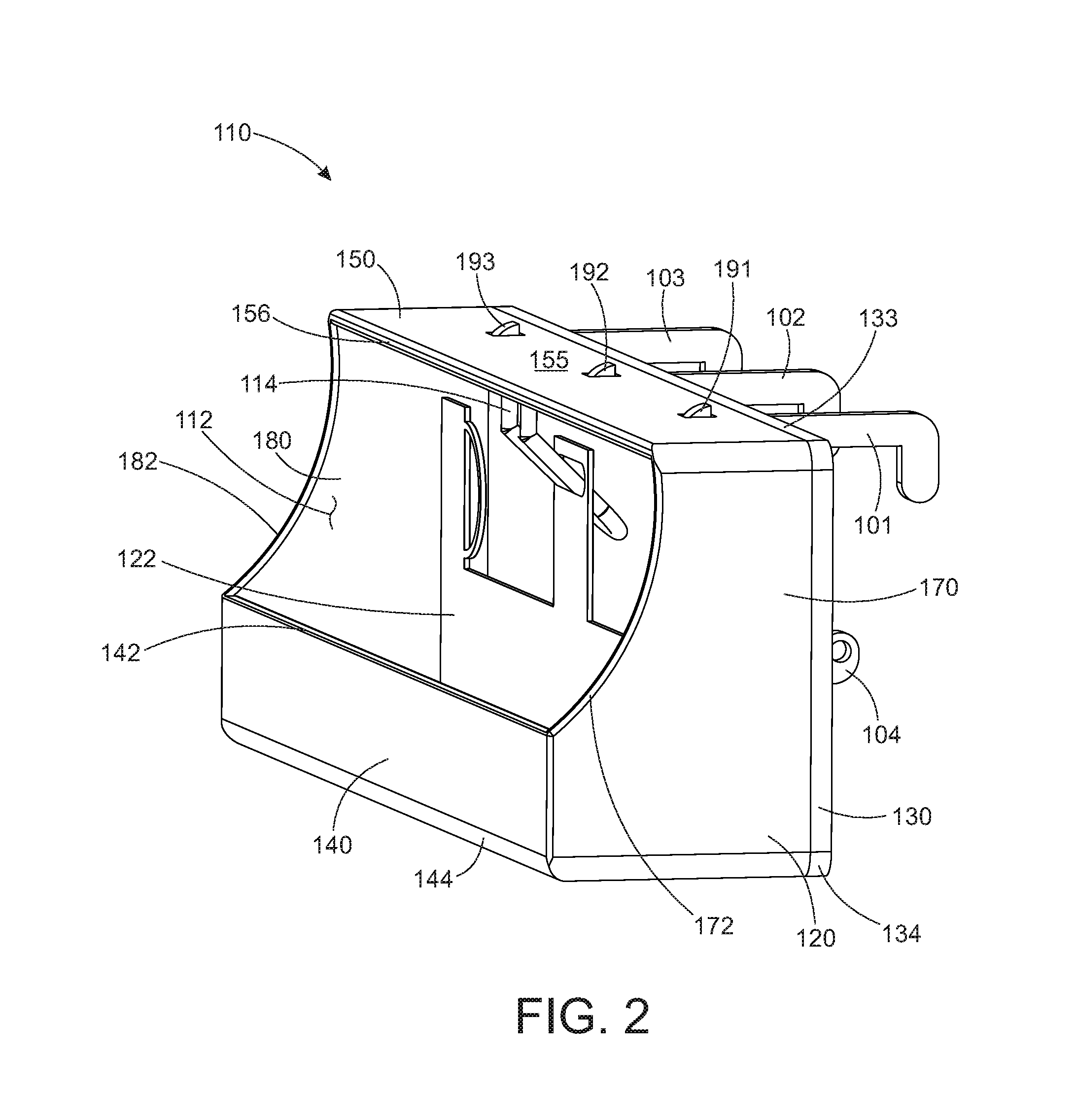
FIG. 2 shows a perspective view of a shopping cart bagging station holding at least one shopping bag;
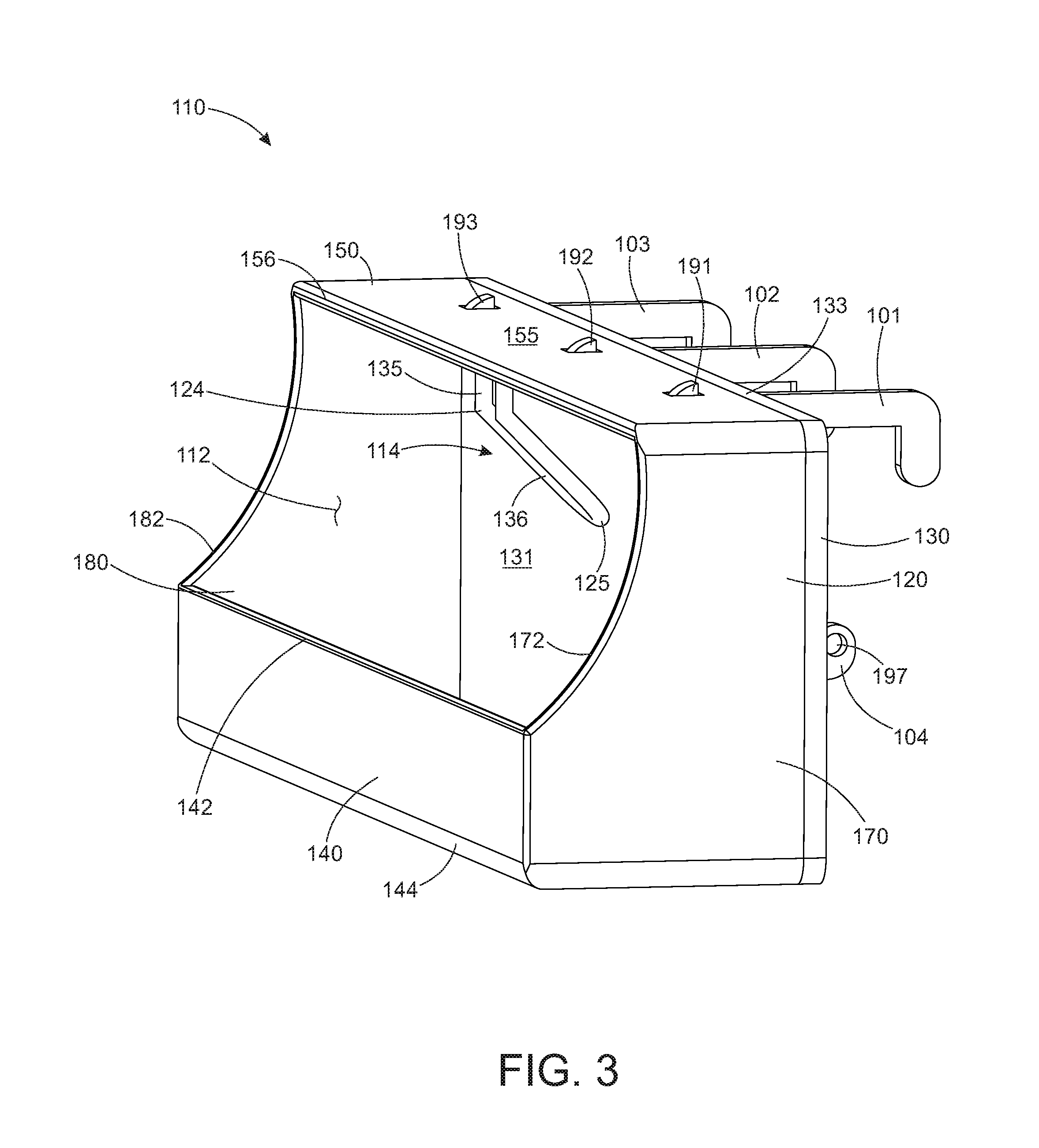
FIG. 3 shows a front perspective view of the shopping cart bagging station of FIG. 2;
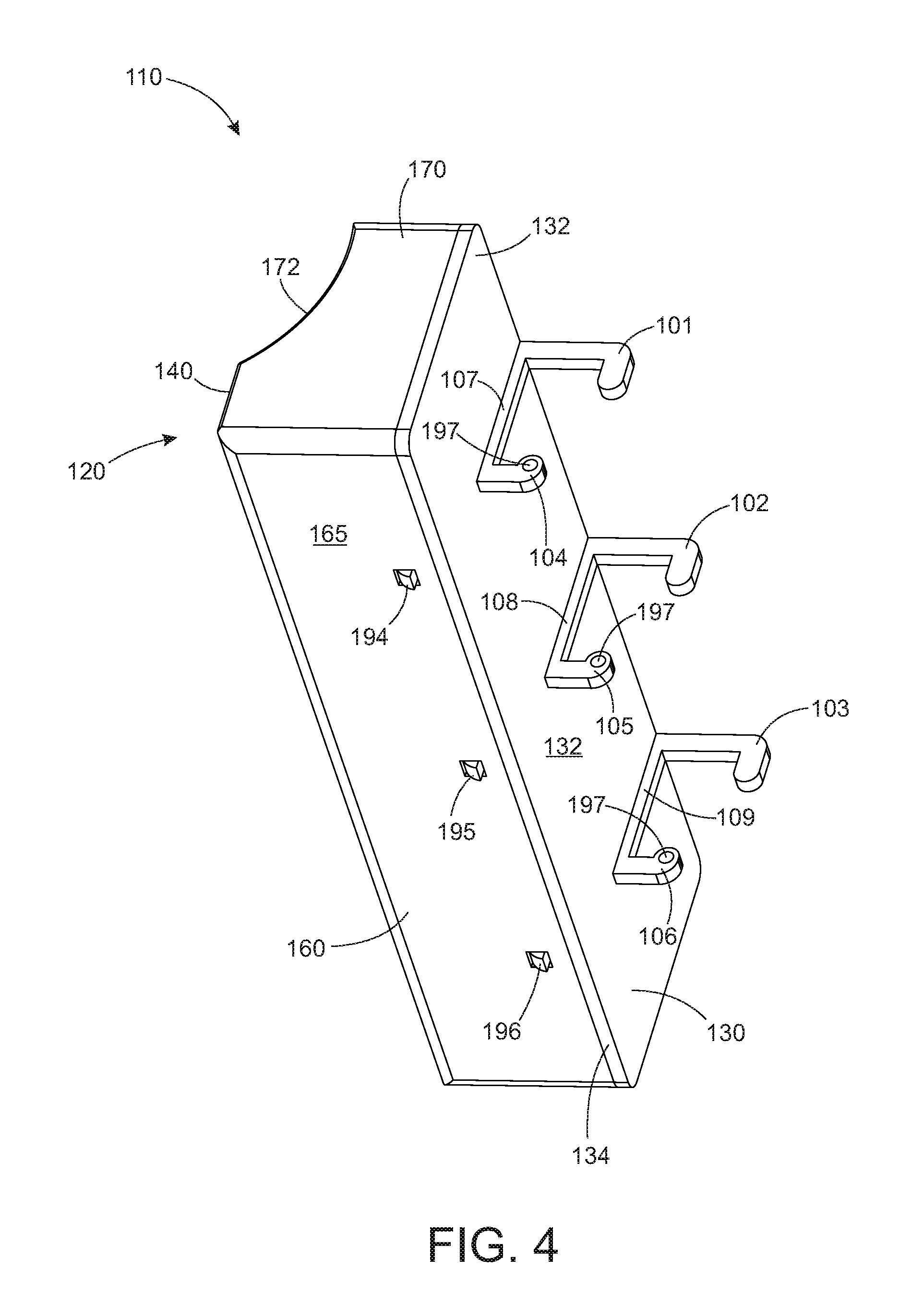
FIG. 4 shows a rear perspective view of the shopping cart bagging station of FIG. 2;
FIG. 5 shows a side view of the shopping cart bagging station of FIG. 2;
FIG. 6 shows a front perspective view of a box front portion;
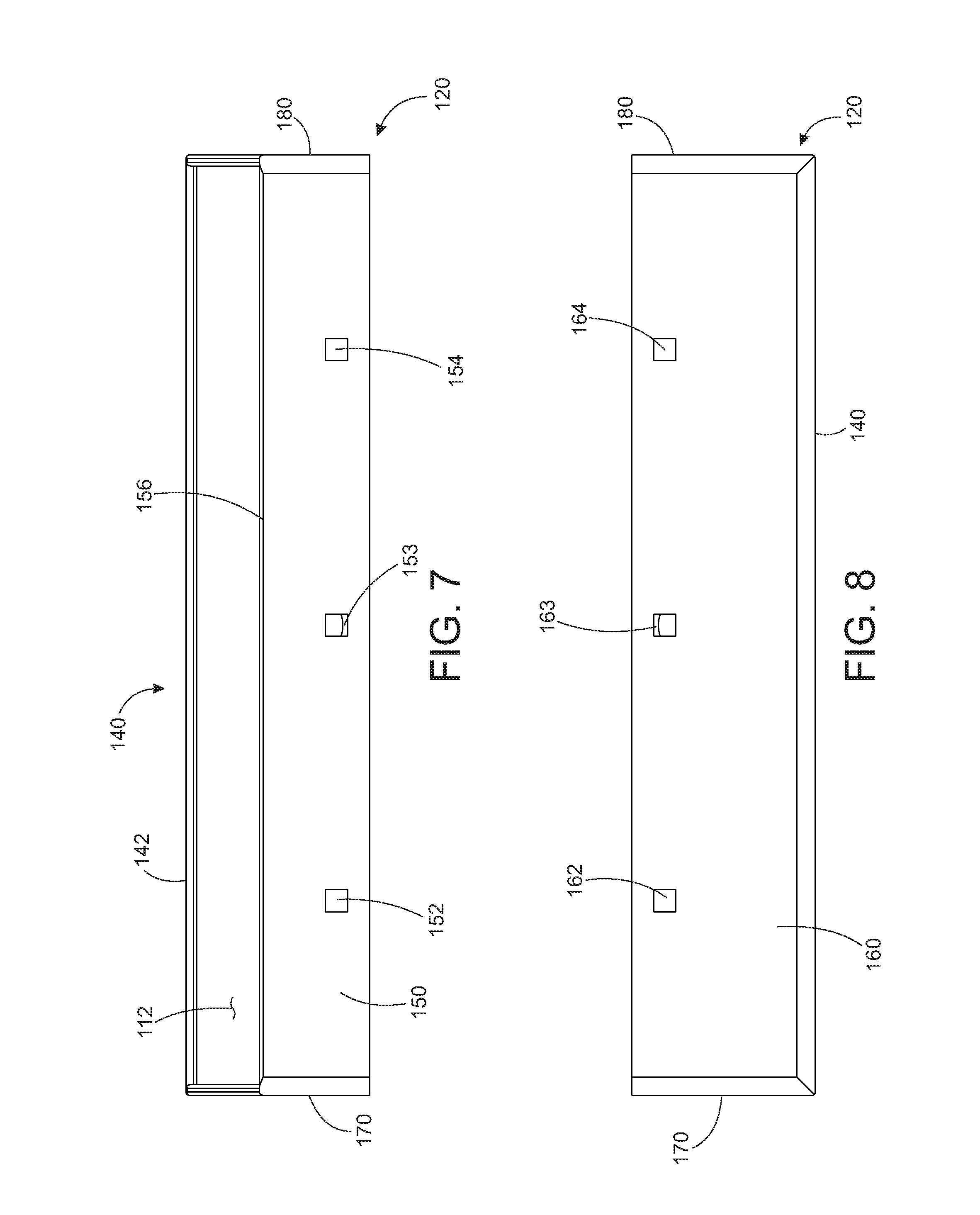
FIG. 7 shows a top view of the box front portion of FIG. 6;
FIG. 8 shows a bottom view of the box front portion of FIG. 6;
FIG. 9 shows a front perspective view of a further embodiment of a box front portion;
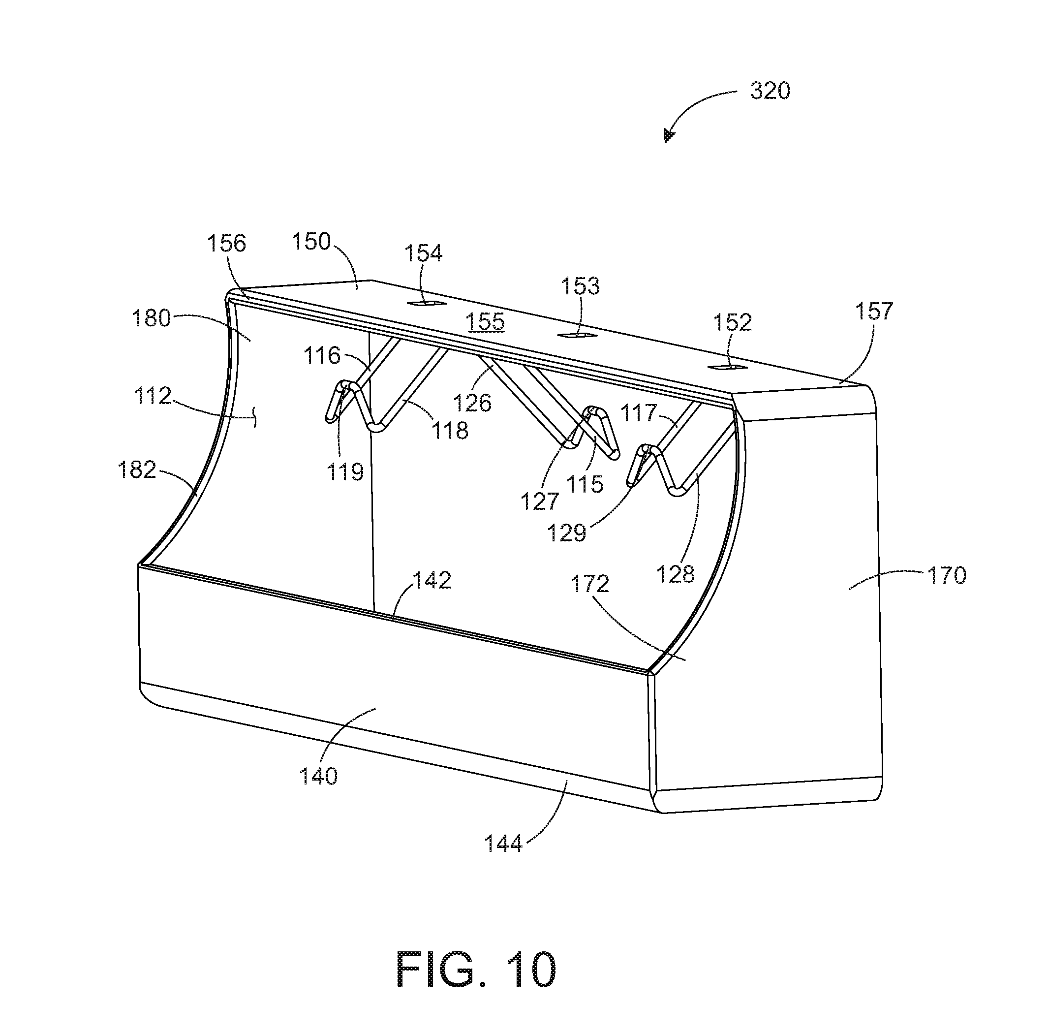
FIG. 10 shows a front perspective view of an additional embodiment of a box front portion;
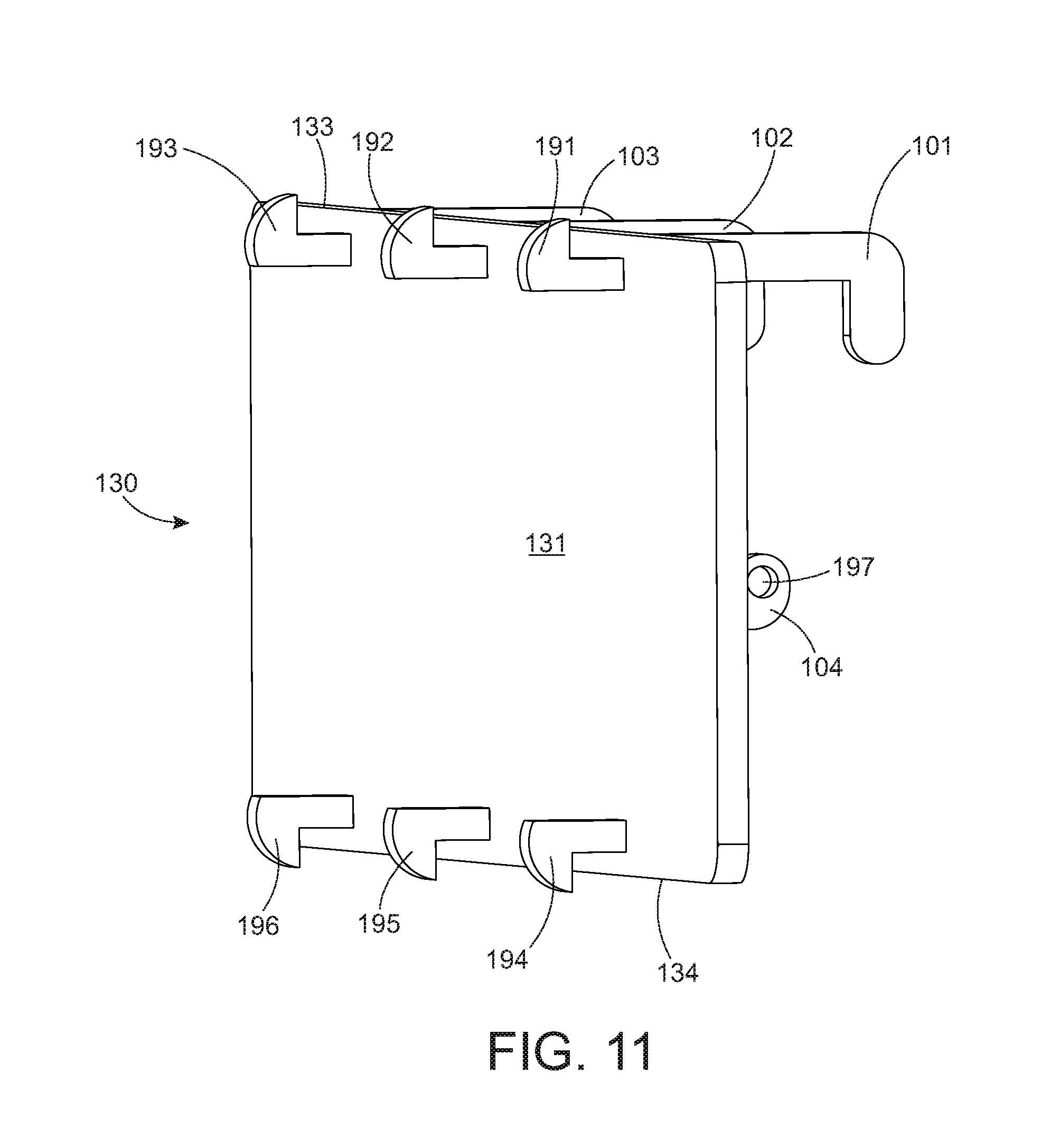
FIG. 11 shows a front perspective view of a back plate;
FIG. 12 shows a rear perspective view of the back plate of FIG. 11; and
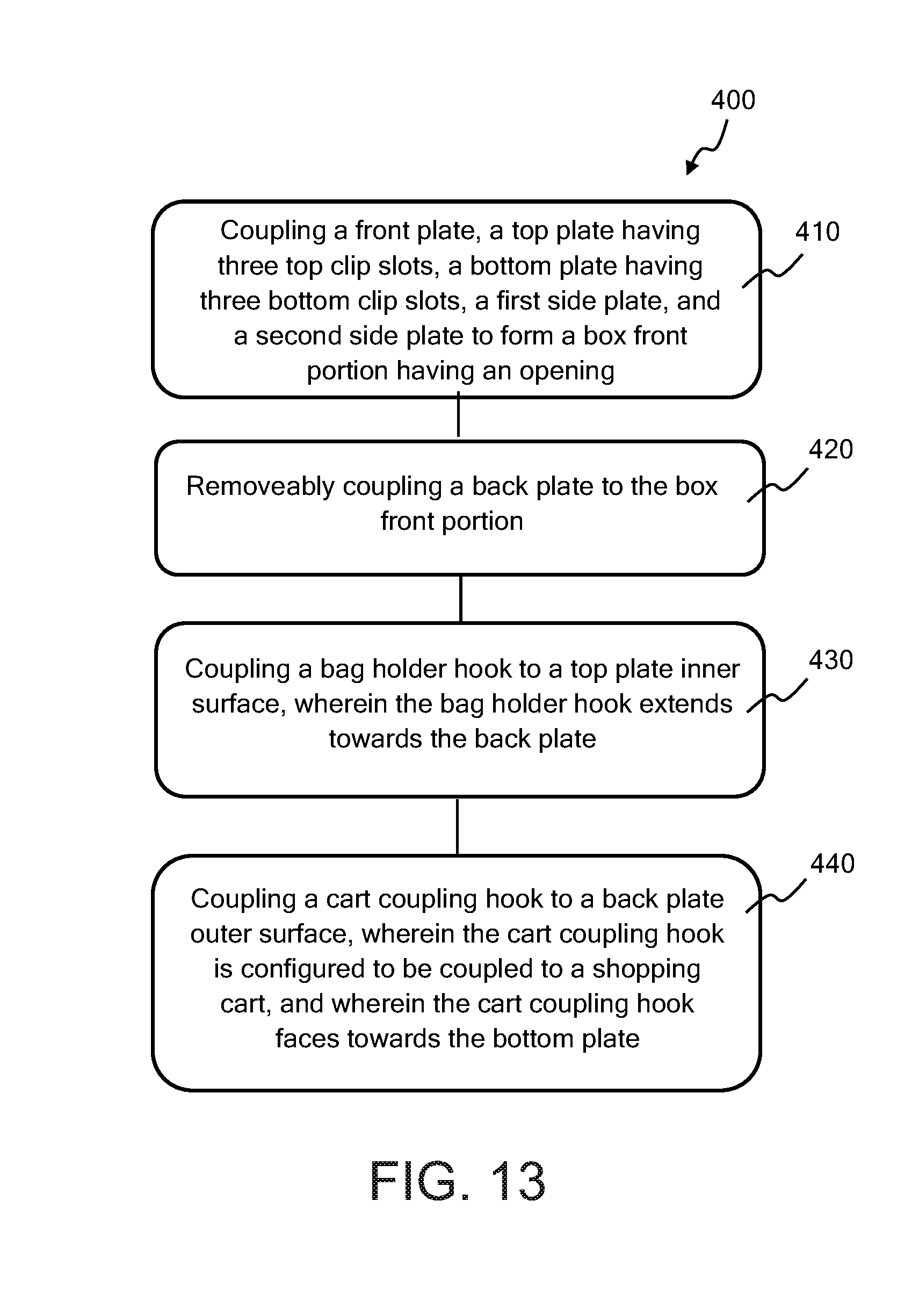
FIG. 13 illustrates a method of assembling a shopping cart bagging station.
DETAILED DESCRIPTION OF EMBODIMENTS OF THE INVENTION
Disclosed herein are embodiments of an invention related to retail store fixtures, and, more specifically, to a bagging station that couples to a shopping cart. The disclosed shopping cart bagging station can be used by customers to bag their purchases as they shop. The disclosed shopping cart bagging station includes a box front portion and a back plate that couple together to form a rectangular enclosure for shopping bags. The box front portion has at least one bag holder hook inside the enclosure that shopping bags are hung from. An opening in the box front portion is used to access the shopping bags hanging from the bag holder hook in the enclosure. At least one cart coupling hook is coupled to the back plate to couple the shopping cart bagging station to a shopping cart.
A bagging station holds and dispenses shopping bags. Bagging stations are often located at checkout counters in retail stores so that items that have been purchased can be bagged. Bags are opened one at a time and filled with one or more items that have been purchased. When one bag is full, it is removed from the bagging station and the next bag is opened and filled if needed. The disclosed shopping cart bagging station is hung from a shopping cart so that customers can bag their purchased items as they shop. A customer using electronic checkout no longer needs to visit the checkout counter to pay for items. Using the shopping cart bagging station provides the customer the means to bag their items while they shop. The disclosed shopping cart bagging station has a box-type enclosure that keeps the unfilled bags from interfering with products or filled bags in the shopping cart.
FIG. 1 shows a perspective view of one embodiment of a shopping cart bagging station 110 hung from a shopping cart 113. Shopping cart bagging station 110 is hung from a side 111 of shopping cart 113 using cart coupling hooks 101, 102, and 103. Shopping cart bagging station 110 holds one or more than one shopping bag 122 (FIG. 1 and FIG. 2). Shopping bag 122 is hung from a bag holder hook 114 inside of shopping cart bagging station 110. A customer using shopping cart 113 can use shopping cart bagging station 110 to hold and dispense shopping bags as they shop. When the customer wishes to fill shopping bag 122, shopping bag 122 is accessed through an opening 112 (FIG. 2) to open and fill shopping bag 122. Shopping bag 122 is opened and filled while hanging from bag holder hook 114, or, shopping bag 122 can be removed from bag holder hook 114 to be filled. Shopping cart bagging station 110 has a box front portion 120 that partially encloses shopping bag 122 so that shopping bag 122 does not interfere with other items in shopping cart 113. FIG. 1 shows shopping cart bagging station 110 coupled to a side 111 of shopping cart 113, but this is not meant to be limiting. Shopping cart bagging station 110 can be coupled to the front, sides, back, interior, or exterior of shopping cart 113. Shopping cart bagging station 110 can be coupled to many different forms of shopping carts.
FIG. 2 through FIG. 5 show details of shopping cart bagging station 110 of FIG. 1. FIG. 2 shows a front perspective view of shopping cart bagging station 110 holding at least one shopping bag 122. Shopping bag 122 can be one shopping bag or a stack of shopping bags. FIG. 3 shows a front perspective view of shopping cart bagging station 110 with no shopping bags. FIG. 4 shows a rear perspective view of shopping cart bagging station 110, and FIG. 5 shows a side view of shopping cart bagging station 110.
Shopping cart bagging station 110 includes a box front portion 120, a back plate 130, a bag holder hook 114, cart coupling hooks 101, 102, and 103, and an opening 112 in box front portion 120. Back plate 130 is removeably coupled to box front portion 120 to form an enclosure for shopping bag 122. Shopping bag 122 hangs from bag holder hook 114. Opening 112 provides access to shopping bag 122. Cart coupling hooks 101, 102, and 103 couple shopping cart bagging station 110 to shopping cart 113.
Box front portion 120 is generally in the shape of a rectangular enclosure with an open back, in this embodiment. FIG. 6 through FIG. 8 shows details of box front portion 120 and bag holder hook 114. FIG. 6 shows a front perspective view of box front portion 120. FIG. 7 and FIG. 8 shows bottom and top views, respectively, of box front portion 120.
Box front portion 120 includes a front plate 140, a top plate 150, a bottom plate 160, a first side plate 170, and a second side plate 180, as shown in FIG. 1 through FIG. 8. Front plate 140, top plate 150, bottom plate 160, first side plate 170, and second side plate 180 are coupled together to form a rectangular enclosure with no back and with opening 112 in box front portion 120. In this embodiment, front plate 140, top plate 150, bottom plate 160, first side plate 170, and second side plate 180 are formed as an integral structure, but this is not meant to be limiting. In some embodiments, front plate 140, top plate 150, bottom plate 160, first side plate 170, and second side plate 180 are separate plates or elements that are coupled together. Back plate 130 is coupled to box front portion 120 to form a rectangular enclosure with opening 112. Box front portion 120 with back plate 130 coupled to box front portion 120 form an enclosure around shopping bag 122 hanging from bag holder hook 114.
Top plate 150 is a flat rectangular plate of rigid material in this embodiment, best seen in FIG. 7. Top plate 150 has a top plate front edge 156 that is a defining (or bounding) edge of opening 112. Top plate 150 includes three top clip slots 152, 153, and 154. Top clip slots 152, 153, and 154 are rectangular holes through top plate 150 that are used to couple back plate 130 to top plate 140, see FIG. 2, FIG. 3, and FIG. 5. Top clip slots 152, 153, and 154 do not extend to (or open to) an edge of top plate 150, in this embodiment.
Bag holder hook 114 is coupled to an inner surface 151 of top plate 150 (FIG. 5). Bag holder hook 114 holds shopping bag 122 and extends towards back plate 130 (FIG. 5). Bag holder hook 114 is an elongate member formed of a rigid material. In this embodiment, bag holder hook 114 is formed of two metal or plastic rods extending side-by side and coupled together at a bag holder hook second end 125, but this is not meant to be limiting. Bag holder hook 114 has a bag holder hook first end 123 and a bag holder hook second end 125 opposing bag holder hook first end 123, best seen in FIG. 5. Bag holder hook 114 has a bag holder hook first bend 124 that divides bag holder hook 114 into a straight hook top section 135 and a straight hook bottom section 136. Hook top section 135 is coupled to and extends from inner surface 151 of top plate 150. In this embodiment, hook top section 135 is perpendicular to top plate 150. Hook top section 150 extends from bag holder hook first end 123 to bag holder bend 124. Bag holder hook first end 123 is coupled to inner surface 151. Hook bottom section 136 extends from bag holder bend 124 to bag holder hook second end 125. Bag holder hook bend 124 forms an angle 137 between hook top section 135 and hook bottom section 136. Angle 137 is about 135 degrees in this embodiment. In some embodiments, angle 137 is between 115 and 155 degrees. Angle 137 with values in the range of 115 to 155 degrees provide for a bag holder hook 114 that holds shopping bag 122 but does not make it difficult to add or remove shopping bag 122 from bag holder hook 114. Hook top section 135 and hook bottom section 136 are straight in this embodiment, but this is not meant to be limiting (see bag holder hook 115 shown in FIG. 9 and FIG. 10 and described herein, for example). In this embodiment, bag holder hook 114 extends towards back plate 130. Bag holder hook 114 extending towards back plate 130 means that bag holder hook bend 124 bends bag holder hook 114 towards back plate 130, and away from front plate 140. Having bag holder hook 114 extending towards back plate 130 allows shopping bag 122 to be hung from bag holder hook 114, but tends to keep shopping bag 122 from sliding off of bag holder hook 114 and out of shopping cart bagging station 110. When shopping bag 122 is removed from bag holder hook 114, shopping bag 122 is not slid off of bag holder hook 114, but torn off. This is how a shopping bag hanger hole of each shopping bag 122 is designed to work--the hanger hole is torn when opening shopping bag 122 and when removing shopping bag 122 from bag holder hook 114. Since shopping bag 122 does not have to be removed from bag holder hook 114 with the hanger hole intact, it is preferable to have bag holder hook 114 extend towards back plate 130. It is easier to tear the hole and remove shopping bag 122 when bag holder hook 114 extends towards back plate 130.
Bottom plate 160 is a rectangular shaped flat plate formed of rigid material in this embodiment, best seen in FIG. 8. Bottom plate 160 is larger than top plate 150 because opening 112 extends through a portion of top plate 150, see FIG. 3, FIG. 5 and FIG. 7. Bottom plate 160 has three bottom clip slots 162, 163, and 164, as shown in FIG. 8. Bottom clip slots 162, 163, and 164 are each rectangular holes through bottom plate 160. Bottom clip slots 162, 163, and 164 are used to couple back plate 130 to bottom plate 160, see FIG. 4 and FIG. 5. Bottom clip slots 162, 163, and 164 do not open to an edge of bottom plate 160, in this embodiment.
Front plate 140 is rectangular in this embodiment, with a front plate top edge 142 that is an edge of opening 112. Front plate 140 is smaller than opening 112, best seen in FIG. 2 and FIG. 3. Front plate 140 being smaller than opening 112 means that front plate 140 has a front plate area that is smaller than an opening area of opening 112.
First side plate 170 is a flat plate of rigid material with five edges. First side plate 170 has four straight edges and one curved cutout along a first side curved edge 172 where opening 112 extends to first side plate 170, see FIG. 2, FIG. 3, and FIG. 6. Similarly, second side plate 180 is a flat five-edged plate of rigid material, with four straight edges and a curved cutout along a second side curved edge 182 where opening 112 extends to second side plate 180.
Opening 112 is configured to allow shopping bag 122 to be inserted into and removed from shopping cart bagging station 110. Shopping bag 122, which can be one shopping bag or a stack of shopping bags, is hung on bag holder hook 114 by putting shopping bag 122 into box front portion 120 through opening 112, and hanging shopping bag 122, or the whole stack of shopping bags, on bag holder hook 114 by extending bag holder hook 114 through the hanger hole in shopping bag 122. In this embodiment, there are no hooks for hanging the handles of shopping bag 122 from, but this is not meant to be limiting. In some embodiments, shopping cart bagging station 110 includes hooks for hanging the handles of shopping bag 122 from (see, for example FIG. 9 and FIG. 10 and the accompanying description). When it is desired to open shopping bag 122, shopping bag 122 is opened by tearing the front side of shopping bag 122 off of bag holder hook 114 and filling shopping bag 122. Shopping bag 122 can be filled while it is inside of shopping cart bagging station 110 or while it hangs partially inside and partially outside of shopping cart bagging station 110. Once shopping bag 122 is filled, the back side of shopping bag 122 is torn off of bag holder hook 114, and shopping bag 122 is removed from shopping cart bagging station 110 through opening 112. If it is desired to fill another shopping bag, the next shopping bag hanging from bag holder hook 114 can be similarly opened and filled. Shopping cart bagging station 110 is smaller than many shopping bags, so the shopping bags can be rolled or folded up in the bottom of shopping cart bagging station 110. Having shopping cart bagging station 110 be smaller than the shopping bags helps keep shopping cart bagging station 110 small and helps keep shopping bag 122 that is hanging inside of shopping cart bagging station 110 from interfering with or getting tangled with other items or bags that are inside of shopping cart 113.
Opening 112 is through a portion of front plate 140, top plate 150, first side plate 170, and second side plate 180. Top plate 150 is smaller than bottom plate 160 (FIG. 3, FIG. 5, FIG. 7, and FIG. 8), because opening 112 extends through a portion of top plate 150. Opening 112 is larger than front plate 140, see FIG. 3 and FIG. 6.
Opening 112 extends through a portion of first side plate 170 and second side plate 180, see FIG. 3. First side plate 170 has a first side curved edge 172 that extends from a top plate front edge 156 to a front plate top edge 142. First side curved edge 172 defines an edge of opening 112. Second side plate 180 has a second side curved edge 182 that extends from top plate front edge 156 to front plate top edge 142. Second side curved edge 182 defines another edge of opening 112. Opening 112 is defined or bounded by top plate front edge 156, first side curved edge 172, front plate top edge 142, and second side plate curved edge 182, as shown in the figures. Opening 112 is fairly large so that hands can easily reach into shopping cart bagging station 110 to hang shopping bag 122, fill shopping bag 122, and remove shopping bag 122.
In the embodiment shown in FIG. 1 through FIG. 8, shopping cart bagging station 110 has one bag holder hook 114, but this is not meant to be limiting. In some embodiments, shopping cart bagging station 110 includes more than one bag holder hook 114. In some embodiments, shopping cart bagging station 110 includes one or more handle holder hooks. FIG. 9 shows an embodiment of a box front portion 220. Box front portion 220 can be used in place of box front portion 120 of shopping cart bagging station 110. FIG. 10 shows an embodiment of a box front portion 320. Box front portion 320 can be used in place of box front portion 120 of shopping cart bagging station 110.
Box front portion 220 shown in FIG. 9 is the same as box front portion 120 except that box front portion 220 includes two handle holder hooks 116 and 117, and bag holder hook 114 is replaced with bag holder hook 115. Bag holder hook 115 is similar to bag holder hook 114 and used for the same purpose. Bag holder hook 115 is used in place of bag holder hook 114 in box front portion 220. The difference between bag holder hook 114 and bag holder hook 115 is that bag holder hook 115 is a J-hook, meaning bag holder hook 115 has a bag holder hook second end 127 that is upturned like the letter J. Bag holder hook 115 has a bag holder hook first end 126 coupled to top plate 150, and bag holder hook second end 127 that opposes bag holder hook first end 126. Bag holder hook 115 extends towards the back of box front portion 220, towards back plate 130 when box front portion 220 is coupled to back plate 130. Bag holder hook second end 127 is upturned towards top plate 150 to more easily catch and hold one or more shopping bags.
Box front portion 220 also includes a first handle holder hook 116 and a second handle holder hook 117. First and second handle holder hooks 116 and 117 are coupled to top plate inner surface 151 of top plate 150 on either side of bag holder hook 115, as shown in FIG. 9. First and second handle holder hooks 116 and 117 are used to hang shopping bag handles on. One or more shopping bags are hung by the hanger hole on bag holder hook 115. One handle for the one or more shopping bags are hung from first handle holder hook 116, and the other handle for the one or more shopping bags is hung from second handle holder hook 117. First and second handle holder hooks 116 and 117 are each J-hooks similar to bag holder hook 115.
First handle holder hook 116 has a first handle holder hook first end 118 coupled to top plate 150, and a first handle holder hook second end 119 opposing first handle holder hook first end 118. First handle holder hook second end 119 is upturned to make first handle holder hook 116 into a J shape.
Second handle holder hook 117 has a second handle holder hook first end 128 coupled to top plate 150, and a second handle holder hook second end 129 opposing second handle holder hook first end 128. Second handle holder hook second end 129 is upturned to make second handle holder hook 117 into a J shape. In the embodiment of box front portion 220 shown in FIG. 9, bag holder hook 115 and first and second handle holder hooks 116 and 117 all face the back side of box front portion 220. When box front portion 220 is coupled to back plate 130, bag holder hook 115 and first and second handle holder hooks 116 and 117 all face back plate 130.
Box front portion 320 shown in FIG. 10 is the same as box from portion 220 except that first and second handle holder hooks 116 and 117 face front plate 140. First and second handle holder hooks 116 and 117 facing front plate 140 means that first and second handle holder hooks 116 and 117 extend towards front plate 140. Having first and second handle holder hooks 116 and 117 extend towards front plate 140 can be desired in some situations where the customer does not wish to tear the handle of the shopping bags when the handles are removed from first and second handle holder hooks 116 and 117.
Other configurations of bag holder hook 115 and first and second handle holder hooks 116 and 117 can be used for different uses of shopping cart bagging station 110. In some embodiments, bag holder hook 115 and first and second handle holder hooks 116 and 117 all face front plate 140. In some embodiments, bag holder hook 115 faces front plate 140 and first and second handle holder hooks 116 and 117 face back plate 130. In some embodiments, bag holder hook 115 and first and second handle holder hooks 116 and 117 are coupled to top plate 150 such that they can be rotated by the customer to face the direction the customer desires.
Referring back to FIG. 1 through FIG. 8 and FIG. 11 and FIG. 12, back plate 130 is removeably coupled to box front portion 120 (or box front portion 220 or box front portion 320). Back plate 130 includes at least one locking clip that removeably couples back plate 130 to box front portion 120, as shown in FIG. 2 through FIG. 5. FIG. 11 and FIG. 12 show details of back plate 130. FIG. 11 shows a front perspective view of back plate 130. FIG. 12 shows a rear perspective view of back plate 130. In the embodiment shown in the figures, back plate 130 includes six locking clips, three back plate top locking clips 191, 192, and 193, and three back plate bottom locking clips 194, 195, and 196, as best seen in FIG. 11. Back plate 130 is rectangular in shape in this embodiment, and removeably couples to box front portion 120 as shown in FIG. 1 through FIG. 5. With back plate 130 coupled to box front portion 120, an enclosure for bag holder hook 114 is formed by the combination of box front portion 120 and back plate 130.
Back plate 130 has an inner surface 131 (FIG. 11), an outer surface 132 (FIG. 12), a back plate top edge 133, and a back plate bottom edge 134. Three top locking clips 191, 192, and 193 extend from, and are coupled to, back plate inner surface 131 adjacent back plate top edge 133, as shown in FIG. 11. Three bottom locking clips 194, 195, and 196 extend from, and are coupled to, back plate inner surface 131 of back plate 130 adjacent back plate bottom edge 134. Top locking clips 191, 192, and 193 are each hook-shaped structures that engage with one of top clip slots 152, 153, and 154 of top plate 150 to removeably couple back plate 130 to top plate 150. Top locking clips 191, 192, and 193 each have a shaft that is perpendicular to back plate 130. Top locking clip 191 couples to top clip slot 152 to couple back plate 130 to top plate 150. Top locking clip 191 extends through top clip slot 152 of top plate 150 from top plate inner surface 151 to a top plate outer surface 155, as shown in FIG. 5. Top locking clip 191 extending through top clip slot 152 of top plate 150 from top plate inner surface 151 to top plate outer surface 155 means that top locking clip 191 is extended through top clip slot 152 starting from top plate inner surface 151. Top locking clip 191 extends all the way through top clip slot 152 and extends out of top clip slot 152, sticking out top plate outer surface 155. Top locking clip 192 couples to top clip slot 153 to couple back plate 130 to top plate 150. Top locking clip 192 extends through top clip slot 153 of top plate 150 from top plate inner surface 151 to top plate outer surface 155. Top locking clip 193 couples to top clip slot 154 to couple back plate 130 to top plate 150. Top locking clip 193 extends through top clip slot 154 of top plate 150 from top plate inner surface 151 to top plate outer surface 155.
Similarly, bottom locking clips 194, 195, and 196 are each hook-shaped structures that engage with one of bottom clip slots 162, 163, and 164 of bottom plate 160 to removeably couple back plate 130 to bottom plate 150. Bottom locking clips 194, 195, and 196 each have a shaft that is perpendicular to back plate 130. Bottom locking clip 194 couples to bottom clip slot 162 to couple back plate 130 to bottom plate 160. Bottom locking clip 194 extends through bottom clip slot 162 of bottom plate 160 from a bottom plate inner surface 161 to a bottom plate outer surface 165, as shown in FIG. 5. Bottom locking clip 195 couples to bottom clip slot 163 to couple back plate 130 to bottom plate 160. Bottom locking clip 195 extends through bottom clip slot 163 of bottom plate 160 from bottom plate inner surface 161 to bottom plate outer surface 165. Bottom locking clip 196 couples to bottom clip slot 164 to couple back plate 130 to bottom plate 160. Bottom locking clip 196 extends through bottom clip slot 164 of bottom plate 160 from bottom plate inner surface 161 to bottom plate outer surface 165.
Top locking clips 191, 192, and 193, and bottom locking clips 194, 195, and 196 are flexible enough to bend slightly when back plate 130 is pressed against box front portion 120. Top locking clips 191, 192, and 193, and bottom locking clips 194, 195, and 196 give slightly and then engage with their respective top clip slots 152, 153, or 154, or bottom clip slots 162, 163, or 164 to removeably couple back plate 130 to box front portion 120.
Shopping cart bagging station 110 includes at least one cart coupling hook that couples shopping cart bagging station 110 to shopping cart 113. Shopping cart bagging station 110, in the embodiment shown in the figures, includes three cart coupling hooks, first cart coupling hook 101, second cart coupling hook 102, and third cart coupling hook 103, see FIG. 2, FIG. 3, FIG. 4, and FIG. 12. Each one of first cart coupling hook 101, second cart coupling hook 102, and third cart coupling hook 103 are configured to be coupled to shopping cart 113. Each one of first cart coupling hook 101, second cart coupling hook 102, and third cart coupling hook 103 are coupled to and extend from back plate outer surface 132 adjacent back plate top edge 133, see FIG. 12. Each one of first cart coupling hook 101, second cart coupling hook 102, and third cart coupling hook 103 are hook shaped and hook onto or hang from a rod of shopping cart 113 to couple shopping cart bagging station 110 to shopping cart 113. Each one of first cart coupling hook 101, second cart coupling hook 102, and third cart coupling hook 103 face towards bottom plate 160 because cart coupling hooks 101, 102, and 103 are meant to hang from shopping cart 113, not to have items hang from themselves. Having each one of first cart coupling hook 101, second cart coupling hook 102, and third cart coupling hook 103 face bottom plate 160 means the hook opening of each of hooks 101, 102, and 103 face bottom plate 160 and back plate bottom edge 134.
First cart coupling hook 101 includes a hook shaft 174 and a hook end 175. Hook shaft 174 is an elongate rod or bar of rigid material having a hook shaft first end 176 and a hook shaft second end 177 opposing hook shaft first end 176. Hook shaft first end 176 is coupled to back plate outer surface 132. Hook shaft 174 is perpendicular to back plate 130. Hook end 175 is coupled to hook shaft second end 177. Hook end 175 is perpendicular to hook shaft 174 in this embodiment, but this is not meant to be limiting. Hook end 175 forms the hook that grabs shopping cart 113. Hook end 175 extends from hook shaft second end 177 in a direction towards back plate bottom edge 134. Second and third cart coupling hooks 102 and 103 are similarly shaped.
Shopping cart bagging station 110 also includes three stabilizer bars 104, 105, and 106 coupled to and extending from back plate outer surface 132, see FIG. 4 and FIG. 12. First stabilizer bar 104 is coupled to and extends from back plate outer surface 132 of back plate 130. First stabilizer bar 104 is an elongate rod or bar with a stabilizer bar first end 183 and a stabilizer bar second end 184 opposing stabilizer bar first end 183. Stabilizer bar first end 183 is coupled to back plate outer surface 132. Stabilizer bar second end 184 has a stabilizer bar hole 197 through stabilizer bar second end 184, see FIG. 12. First stabilizer bar 104 extends from back plate 130 in a direction perpendicular to back plate 130. A connecting bar 107 extends along back plate outer surface 132 between first cart coupling hook 101 and first stabilizer bar 104. First connecting bar 107 is an elongate member of rigid material coupled to and extending flush with back plate outer surface 134, see FIG. 12. First connecting bar 107 has a connecting bar first end 185 coupled to hook shaft first end 176. First connecting bar 107 has a connecting bar second end 186 opposing connecting bar first end 185. Connecting bar second end 186 is coupled to first stabilizer bar first end 183
When shopping cart bagging station 110 is hung from shopping cart 113, first stabilizer bar 104 extends through side 111 of shopping cart 113 to stabilize shopping cart bagging station 110, keeping shopping cart bagging station 110 from rocking on shopping cart 113. First stabilizer bar 104 has stabilizer bar hole 197 stabilizer bar second end 184. Stabilizer bar hole 197 can be used to hang items from or to tie or couple shopping cart bagging station 110 to shopping cart 113 or another item. Connecting bar 107 extends along back plate outer surface 132 between first cart coupling hook 101 and first stabilizer bar 104, which adds strength and stability to cart coupling hook 101, first stabilizer bar 104, and back plate 130.
Similarly, second stabilizer bar 105 and third stabilizer bar 106 are coupled to and extend from back plate outer surface 132 of back plate 130. Second and third stabilizer bars 105 and 106 extend from back plate 130 in a direction perpendicular to back plate 130. A connecting bar 108 extends along back plate outer surface 132 between second cart coupling hook 102 and second stabilizer bar 105. A connecting bar 109 extends along back plate outer surface 132 between third cart coupling hook 103 and third stabilizer bar 106. Second and third stabilizer bars 105 and 106 extend through side 111 of shopping cart 113 to stabilize shopping cart bagging station 110, keeping shopping cart bagging station 110 from rocking on shopping cart 113.
Second and third stabilizer bars 105 and 106 each have a stabilizer bar hole 197 in their respective distal ends (the end away from back plate 130). Stabilizer bar hole 197 can be used to hang items from or to tie or couple shopping cart bagging station 110 to shopping cart 113 or another item. Connecting bar 108 extends along back plate outer surface 132 between second cart coupling hook 102 and second stabilizer bar 105, adding strength and stability to cart coupling hook 102, second stabilizer bar 105, and back plate 130. Connecting bar 109 extends along back plate outer surface 132 between third cart coupling hook 103 and third stabilizer bar 106, adding strength and stability to cart coupling hook 103, third stabilizer bar 106, and back plate 130.
FIG. 13 illustrates a method 400 of assembling a shopping cart bagging station. Method 400 includes an act 410 of coupling a front plate, a top plate having three top clip slots, a bottom plate having three bottom clip slots, a first side plate, and a second side plate together to form a box front portion having an opening. The opening extends through part of the front plate the top plate and first and second side plates. In some embodiments, the top plate is smaller than the bottom plate. In some embodiments, the first side plate has a first side curved edge. In some embodiments, the second side plate has a second side curved edge.
Method 400 includes an act 420 of removeably coupling a back plate to the box front portion. The back plate includes three top locking clips that extend through the three top clip slots. The back plate also includes three bottom locking clips that extend through the three bottom clip slots. The three top locking clips and the three bottom locking clips couple the back plate to the box front portion.
Method 400 includes an act 430 of coupling a bag holder hook to a top plate inner surface. The bag holder hook extends towards the back plate. The bag holder hook holds at least one shopping bag by putting the bag holder hook through the shopping bag hanger hole. The at least one shopping bag hangs from the bag holder hook.
Method 400 also includes and act 440 of coupling a cart coupling hook to a back plate outer surface. The cart coupling hook is configured to be coupled to a shopping cart, and the cart coupling hook faces towards the bottom plate.
Method 400 can include many other acts. In some embodiments, method 400 includes coupling a first and a second handle holder hook to the top plate inner surface on either side of the bag holder hook. In some embodiments, the bag holder hook, the first and the second handle holder hook all face towards the back plate. In some embodiments, the bag holder hook faces toward the back plate, and the first and the second handle holder hook face toward the front plate. In some embodiment, method 400 includes coupling at least one stabilizer bar having a stabilizer bar hole to the back plate outer surface.
A shopping cart bagging station has been shown and described that provides a bagging station for retail store customers to use to bag their purchases while they shop. The shopping cart bagging station includes an enclosure formed of a box front portion with a removable back plate. A bag holder hook and, in some embodiments, one or more handle holder hook, is hung from an inner surface of the top plate. The bag holder hook holds and dispenses shopping bags. Shopping bags hung from the bag holder hook are partially enclosed by the box front portion and the back plate. The handle holder hooks can be used to hang shopping bag handles from. The box front portion has an opening for reaching into the box front portion to load shopping bags onto the bag holder hook or to retrieve shopping bags from the bag holder hook. The shopping cart bagging station has one or more cart coupling hook that couple the shopping cart bagging station to a shopping cart. The shopping cart bagging station, with at least one shopping bag hung from the bag holder hook, can be used by a customer to dispense shopping bags while the customer shops. The shopping cart bagging station allows customers to bag their purchased items themselves instead of having to visit a checkout station.
The embodiments and examples set forth herein were presented in order to best explain the present invention and its practical application and to thereby enable those of ordinary skill in the art to make and use the invention. However, those of ordinary skill in the art will recognize that the foregoing description and examples have been presented for the purposes of illustration and example only. The description as set forth is not intended to be exhaustive or to limit the invention to the precise form disclosed. Many modifications and variations are possible in light of the teachings above.
* * * * *
D00000
D00001
D00002
D00003
D00004
D00005
D00006
D00007
D00008
D00009
D00010
D00011
D00012
XML
uspto.report is an independent third-party trademark research tool that is not affiliated, endorsed, or sponsored by the United States Patent and Trademark Office (USPTO) or any other governmental organization. The information provided by uspto.report is based on publicly available data at the time of writing and is intended for informational purposes only.
While we strive to provide accurate and up-to-date information, we do not guarantee the accuracy, completeness, reliability, or suitability of the information displayed on this site. The use of this site is at your own risk. Any reliance you place on such information is therefore strictly at your own risk.
All official trademark data, including owner information, should be verified by visiting the official USPTO website at www.uspto.gov. This site is not intended to replace professional legal advice and should not be used as a substitute for consulting with a legal professional who is knowledgeable about trademark law.