Pair of safe pet nail clippers
Zhu , et al. J
U.S. patent number 10,173,332 [Application Number 15/893,765] was granted by the patent office on 2019-01-08 for pair of safe pet nail clippers. This patent grant is currently assigned to SUZHOU PETMATE INDUSTRY & TRADE CO., LTD.. The grantee listed for this patent is Suzhou Petmate Industry & Trade Co., Ltd.. Invention is credited to Xinggen Huang, Haiyuan Zhu.


View All Diagrams
| United States Patent | 10,173,332 |
| Zhu , et al. | January 8, 2019 |
Pair of safe pet nail clippers
Abstract
A pair of safe pet nail clippers includes a first handle and a second handle correspondingly disposed and pivotedly connected to each other. The first and second handles respectively include a blade portion and a handle portion. Blades of the blade portions of the first and second handles are provided in a concave shape. When the handle portions of the first and second handles are relatively opened to the maximum extent, an initial trimming hole is formed between the concave blades of the first and second handles. The first and second handles are provided therebetween with an adjustment mechanism for adjusting the relative opening of the handle portions of the first and second handles and the caliber of the initial trimming hole.
| Inventors: | Zhu; Haiyuan (Suzhou, CN), Huang; Xinggen (Suzhou, CN) | ||||||||||
|---|---|---|---|---|---|---|---|---|---|---|---|
| Applicant: |
|
||||||||||
| Assignee: | SUZHOU PETMATE INDUSTRY & TRADE
CO., LTD. (Suzhou, CN) |
||||||||||
| Family ID: | 59883332 | ||||||||||
| Appl. No.: | 15/893,765 | ||||||||||
| Filed: | February 12, 2018 |
Foreign Application Priority Data
| Jul 10, 2017 [CN] | 2017 1 0555963 | |||
| Current U.S. Class: | 1/1 |
| Current CPC Class: | A01K 13/00 (20130101); B26B 13/16 (20130101); A01K 17/00 (20130101); B26B 13/22 (20130101); B26B 13/08 (20130101) |
| Current International Class: | B26B 13/08 (20060101); A01K 17/00 (20060101); B26B 13/22 (20060101); A01K 13/00 (20060101) |
| Field of Search: | ;30/28,29,119,120,234,233,254-262,271 |
References Cited [Referenced By]
U.S. Patent Documents
| 10972 | May 1854 | Brown |
| 73205 | January 1868 | Sloat |
| 83293 | October 1868 | Lytle |
| 103386 | May 1870 | Stow |
| 106705 | August 1870 | Marsters |
| 137745 | April 1873 | Whitney |
| 139983 | June 1873 | Van Hoosen |
| 149556 | April 1874 | Wolff |
| 156619 | November 1874 | Wolff |
| 203272 | May 1878 | Hill |
| 226358 | April 1880 | Schaffer |
| 247766 | October 1881 | Korn |
| 257982 | May 1882 | Schmidt |
| 280047 | June 1883 | Kully |
| 284968 | September 1883 | Lindsey |
| 332597 | December 1885 | Donovan |
| 340053 | April 1886 | Lytle |
| 365333 | June 1887 | Dickenson |
| 384653 | June 1888 | Vrooman |
| 388957 | September 1888 | De Arment |
| 389925 | September 1888 | Griscom |
| 398509 | February 1889 | Henckels |
| 414528 | November 1889 | Halbehann |
| 419489 | January 1890 | Badger |
| 427245 | May 1890 | Toof |
| 442005 | December 1890 | Bartholomew |
| 471950 | March 1892 | Carmody |
| 492452 | February 1893 | Wright |
| 547101 | October 1895 | Williams |
| 559383 | May 1896 | Honaker |
| 568242 | September 1896 | Fay |
| 598031 | January 1898 | Steen |
| 667914 | February 1901 | Klever, Jr. |
| 673014 | April 1901 | Broadbooks |
| 681327 | August 1901 | Klever, Jr. |
| 690925 | January 1902 | Capewell |
| 726156 | April 1903 | Goldsmith |
| 863111 | August 1907 | Smohl |
| 879618 | February 1908 | Flyberg |
| 881890 | March 1908 | Barr |
| 980861 | January 1911 | Blake |
| 1006936 | October 1911 | Guzman |
| 1011053 | December 1911 | Grizzle |
| 1034947 | August 1912 | Alvord et al. |
| 1062829 | May 1913 | Karsitz |
| 1065741 | June 1913 | Sparks |
| 1080145 | December 1913 | Friederick |
| 1107210 | August 1914 | Adams |
| 1168051 | January 1916 | Bernard |
| RE14169 | July 1916 | Aaron |
| 1205999 | November 1916 | Kirmsee |
| 1227678 | May 1917 | Scott |
| 1252727 | January 1918 | Sedlin |
| 1296660 | March 1919 | Hayden |
| 1331851 | February 1920 | Ouzoun-Boghossian |
| 1349563 | August 1920 | Day |
| 1552495 | September 1925 | Mohr |
| 1592142 | July 1926 | Laubscher |
| 1602451 | October 1926 | Reardon |
| 1648498 | November 1927 | Morgan |
| 1822591 | September 1931 | Hickok |
| 1880951 | October 1932 | Eyre |
| 1904399 | April 1933 | Balthaser |
| 1956588 | May 1934 | Parker et al. |
| 2181056 | November 1939 | Irvine |
| 2480797 | August 1949 | Weber |
| 2491712 | December 1949 | Campbell |
| 2532359 | December 1950 | Drmic |
| 2624114 | January 1953 | Althausen |
| 2650423 | September 1953 | Phillips |
| 2708311 | May 1955 | McCloud |
| 2760390 | August 1956 | Ayer |
| 2801467 | August 1957 | Casanovas |
| 2885781 | May 1959 | Bauer |
| 2910900 | November 1959 | Klein |
| 2929141 | March 1960 | Vosbikian et al. |
| 2932224 | April 1960 | Peed, Jr. et al. |
| 3096581 | July 1963 | Aapro |
| 3371416 | March 1968 | Horton |
| 3559286 | February 1971 | Pfaffenbach |
| 3832771 | September 1974 | Morgan |
| 3834022 | September 1974 | Students |
| 3854202 | December 1974 | Cortese |
| 3972333 | August 1976 | Leveen |
| 4584770 | April 1986 | Sabol |
| 4744147 | May 1988 | Modin |
| 4910870 | March 1990 | Chang |
| 5220856 | June 1993 | Eggert |
| D337247 | July 1993 | Dart |
| 5319854 | June 1994 | Pracht |
| 5498095 | March 1996 | Krivec |
| 5499454 | March 1996 | Compton |
| 5701672 | December 1997 | Wachtel |
| 5749147 | May 1998 | Hasegawa |
| 5890295 | April 1999 | Wachtel |
| 6408523 | June 2002 | Schmidt |
| D472127 | March 2003 | Willinger |
| 6827038 | December 2004 | Dunn |
| 6829828 | December 2004 | Cech |
| 6915575 | July 2005 | Cerutti |
| 7000321 | February 2006 | Rodgers |
| 7124669 | October 2006 | Rodgers |
| 7263775 | September 2007 | Moulton, III |
| 7621011 | November 2009 | Smith |
| D615254 | May 2010 | Manheimer, III |
| 8051572 | November 2011 | Zhang |
| 8074361 | December 2011 | Bohlman |
| 8793883 | August 2014 | Romero |
| 9003667 | April 2015 | Huang |
| 9913457 | March 2018 | Kim |
| 2003/0024543 | February 2003 | Wolf |
| 2006/0158871 | July 2006 | Hopkins |
| 2007/0137041 | June 2007 | Manheimer |
| 2007/0277378 | December 2007 | Kabella |
| 2008/0271324 | November 2008 | Fryer |
| 2009/0078278 | March 2009 | Tran |
| 2009/0241342 | October 2009 | Habib |
| 2011/0005537 | January 2011 | Hsu |
| 2013/0219722 | August 2013 | Cordoba Sanchez |
| 2014/0014042 | January 2014 | Bihlmaier |
| 2014/0101944 | April 2014 | Moultrie |
| 2014/0338201 | November 2014 | Romero |
| 2015/0000139 | January 2015 | Boldt |
| 2015/0101194 | April 2015 | Jui-Tsang |
| 2016/0059427 | March 2016 | Stanley |
| 2016/0066542 | March 2016 | Kearns |
| 2017/0013806 | January 2017 | Bihlmaier |
| 2017/0245469 | August 2017 | Contreras |
| 3701005 | Apr 1988 | DE | |||
Attorney, Agent or Firm: SZDC Law P.C.
Claims
What is claimed is:
1. A pair of safe pet nail clippers, comprising a first member (1) and a second member (2) correspondingly disposed and pivotally connected to each other by a pivot mechanism (8), the first and second members (1, 2) respectively comprising a blade portion (3) and a handle portion (4), characterized in that: with blades (3-1) of the blade portions (3) of the first and second members (1, 2) provided in a concave shape, when the handle portions (4) of the first and second members (1, 2) are relatively opened by the pivot mechanism (8), an initial trimming hole (5) is formed between the concave blades (3-1) of the first and second members (1, 2), with the first and second members (1, 2) provided therebetween with an adjustment mechanism (6) for adjusting the relative opening of the handle portions (4) of the first and second members (1, 2) and a caliber of the initial trimming hole (5), wherein the first and second members (1, 2) are provided therebetween with a reset mechanism (7) for keeping the concave blades (3-1) of the first and second members (1, 2) in the position of the initial trimming hole (5), and the reset mechanism (7) comprises a first spring (7-1) and a second spring (7-2), wherein the first spring (7-1) is sleeved on the first screw (6-2), with one end thereof abutting on the handle portion (4) of the first member (1) and the other end thereof abutting on a first side of the turntable (6-1), and the second spring (7-2) is sleeved on the second screw (6-3), with one end thereof abutting on the handle portion (4) of the second member (2) and the other end thereof abutting on a second side of the turntable (6-1); and wherein the adjustment mechanism (6) comprises a turntable (6-1), a first screw (6-2) located on the first side of the turntable (6-1) and driven to rotate by the turntable (6-1), a second screw (6-3) located on the second side of the turntable (6-1) and driven to rotate by the turntable (6-1), a first limit block (6-4) screwed on the first screw (6-2), and a second limit block (6-5) screwed on the second screw (6-3), wherein the handle portions (4) of the first and second members (1, 2) are provided oppositely with a first mounting slot (6-6) and a second mounting slot (6-7), respectively, into which the first and second screws (6-2, 6-3) are inserted, with the threads on the two screws (6-2, 6-3) arranged in the reverse direction; the first and second limit blocks (6-4, 6-5) are respectively located in the first and second mounting slots (6-6, 6-7) and can move laterally relative to them, with notches of the first and second mounting slots (6-6, 6-7) smaller than the first and second limit blocks (6-4, 6-5); when the turntable (6-1) is rotated, the turntable (6-1) simultaneously drives the first and second screws (6-2, 6-3) to rotate, and the first and second limit blocks (6-4, 6-5) are moved axially close to or away from each other so as to adjust the distance between the first and second limit blocks (6-4, 6-5), thus adjusting the relative opening of the handle portions (4) of the first and second members (1, 2) and the caliber of the initial trimming hole (5).
2. The pair of safe pet nail clippers according to claim 1, characterized in that: the first and second springs (7-1, 7-2) are conical springs, the larger ends thereof respectively abutting on the handle portions (4) of the first and second members (1, 2), the smaller ends thereof respectively abutting on the first and second sides of the turntable (6-1).
3. The pair of safe pet nail clippers according to claim 1, characterized in that: the handle portion (4) of the first member (1) is provided with a first limit lug (1-1) and a first limit groove (1-2) for mounting the blade portion (3), and the handle portion (4) of the second member (2) is provided with a second limit lug and a second limit groove for mounting the blade portion (3), wherein the first limit lug (1-1) is embedded in the second limit groove and can slide relative to the second limit groove, and the second limit lug is embedded in the first limit groove (1-2) and can slide relative to the first limit groove.
4. The pair of safe pet nail clippers according to claim 1, characterized in that: the blade portion (3) of the first member (1), provided with a screw hole (3-2), and the blade portion (3) of the second member (2), provided with a through hole (3-3), are pivoted by the pivot mechanism (8), which comprises a pin (8-1), a nut (8-2) and a corrugated gasket (8-3), with the pin (8-1) passing through the inner hole of the gasket (8-3), the through hole (3-3) and the screw hole (3-2) to pivot the first and second members (1, 2) and get them tightened with the nut (8-2).
5. The pair of safe pet nail clippers according to claim 1, characterized in that: a receiving groove (9), provided at a bottom of the handle portion (4) of the first member (1) or the second member (2), is provided inside with an abrasive rod (10) capable of being pulled out relative to the receiving groove (9).
Description
CROSS-REFERENCE TO RELATED PATENT APPLICATIONS
This application claims the priority benefit of China Patent Application No. 201710555963.1, filed on Jul. 10, 2017, which is incorporated by reference in its entirety.
TECHNICAL FIELD
The present invention relates to a pair of pet nail clippers.
BACKGROUND
With the improvement of people's living standard, pets have entered millions of households. The daily trimming of pets' nails is for not only beauty but also health of pets. Untrimmed nails may cause a variety of health problems. For example, long nails may break, ache and bleed. In extreme cases, nails may curl and grow into the pets' paws. Nails of pets, such as dogs or cats, grow quickly and have to be trimmed once or twice a month.
However, trimming pets' nails also bring some hidden dangers. With the root of a pet's nails rich in blood capillaries, it is generally not easy to judge how long to cut while trimming the pet's nails, and often only until the pet issues a cry or bleeds is the pet found to have been hurt. Besides, since a pair of pet nail clippers is different from that for human's nails and tends to be larger in size and more complicated in structure, a user may not be able to see parts of a pet's nails to be trimmed while trimming the pet's nails due to the blade or other structural portions of the pair of pet nail clippers blocking the line of sight of the user, which makes the pet more vulnerable.
SUMMARY
A purpose of the present invention is to provide a pair of safe pet nail clippers with a higher safety factor, in which the caliber of the initial trimming hole can be adjusted and controlled within a certain range by an adjustment mechanism according to the size of a pet's nails, so as to prevent the pet from being hurt due to excessive trimming and thus be safer to use.
A technical solution of the present invention is as follows: A pair of safe pet nail clippers is provided, comprising a first member and a second member correspondingly disposed and pivotedly connected to each other, the first and second members respectively comprising a blade portion and a handle portion; with blades of the blade portions of the first and second members provided in a concave shape, when the handle portions of the first and second members are relatively opened to the maximum extent, an initial trimming hole is formed between the concave blades of the first and second members, with the first and second members provided therebetween with an adjustment mechanism for adjusting the relative opening of the handle portions of the first and second members and the caliber of the initial trimming hole.
Preferably, the first and second members are provided therebetween with a reset mechanism for keeping the concave blades of the first and second members in the position of the initial trimming hole.
A further technical solution of the present invention is as follows: The adjustment mechanism comprises a turntable, a first screw located on the left side of the turntable and driven to rotate by the turntable, a second screw located on the right side of the turntable and driven to rotate by the turntable, a first limit block screwed on the first screw, and a second limit block screwed on the second screw, wherein the handle portions of the first and second members are provided oppositely with a first mounting slot and a second mounting slot, into which the first and second screws are inserted, with the threads on the two screws arranged in the reverse direction; the first and second limit blocks are respectively located in the first and second mounting slots and can move laterally relative to them, with notches of the first and second mounting slots smaller than the first and second limit blocks; when the turntable is rotated, it simultaneously drives the first and second screws to rotate, and the first and second limit blocks are moved axially close to or away from each other so as to adjust the distance between the first and second limit blocks, thus adjusting the relative opening of the handle portions of the first and second members and the caliber of the initial trimming hole.
The reset mechanism comprises a first spring and a second spring, wherein the first spring is sleeved on the first screw, with one end thereof abutting on the handle portion of the first member and the other end thereof abutting on the left side of the turntable, and the second spring is sleeved on the second screw, with one end thereof abutting on the handle portion of the second member and the other end thereof abutting on the right side of the turntable. Wherein the first and second springs are preferably conical springs, the larger ends thereof abutting on the handle portion of the first or second member, the smaller ends thereof abutting on the left or right side of the turntable. The reset mechanism may also be a reset member disposed between the handle portions of the first and second members. Wherein the reset member may be a spring or an elastic sheet.
Another further technical solution of the present invention is as follows: The adjustment mechanism comprises an adjustment sheet, which is rotatably connected to the first member and provided with multi-level tooth grooves; the second member is provided with a convex tooth portion matched with the tooth grooves; through engagement of the convex tooth portion of the second member with the different tooth grooves of the adjustment sheet, the relative opening of the handle portions of the first and second members and the caliber of the initial trimming hole are adjusted.
The reset mechanism is a reset member disposed between the handle portions of the first and second members. Wherein the reset member may be a spring or an elastic sheet.
Preferably, the handle portion of the first member is provided with a first limit lug and a first limit groove at a connection portion thereof for mounting the blade portion, and the handle portion of the second member is provided with a second limit lug and a second limit groove at a connection portion thereof for mounting the blade portion, wherein the first limit lug is embedded in the second limit groove and can slide relative to the same, and the second limit lug is embedded in the first limit groove and can slide relative to the same.
Preferably, the blade portion of the first member, provided with a screw hole, and the blade portion of the second member, provided with a through hole, are pivoted by a pivot mechanism, which comprises a pin, a nut and a corrugated gasket, with the pin passing through the inner hole of the gasket, the through hole and the screw hole to pivot the first and second members and get them tightened with the nut.
Preferably, a receiving groove, provided at the bottom of the handle portion of the first member or the second member, is provided inside with an abrasive rod capable of being pulled out relative to the same.
Preferably, the concave blade is a concave blade, a U-shaped blade or a V-shaped blade.
The present invention has the following advantages:
1. When the present invention is used, the caliber of the initial trimming hole can be adjusted and controlled within a certain range by an adjustment mechanism according to the size of a pet's nails, so as to prevent the pet from being hurt due to excessive trimming and thus be safer to use.
2. A receiving groove, provided at the bottom of the handle portion of the first or second member of the present invention, is provided inside with an abrasive rod capable of being pulled out relative to the same, so that after a pet's nails are trimmed, the abrasive rod can be pulled out to wear the nails to prevent the pet from hurting a person or damaging an item by scratching since the nails are trimmed too sharp.
BRIEF DESCRIPTION OF DRAWINGS
The present invention will be further described below with reference to drawings and examples.
FIG. 1 is a schematic structural view of Example 1 of the present invention in the initial state;
FIG. 2 is a schematic structural view of FIG. 1 when the blades are closed under an external force;
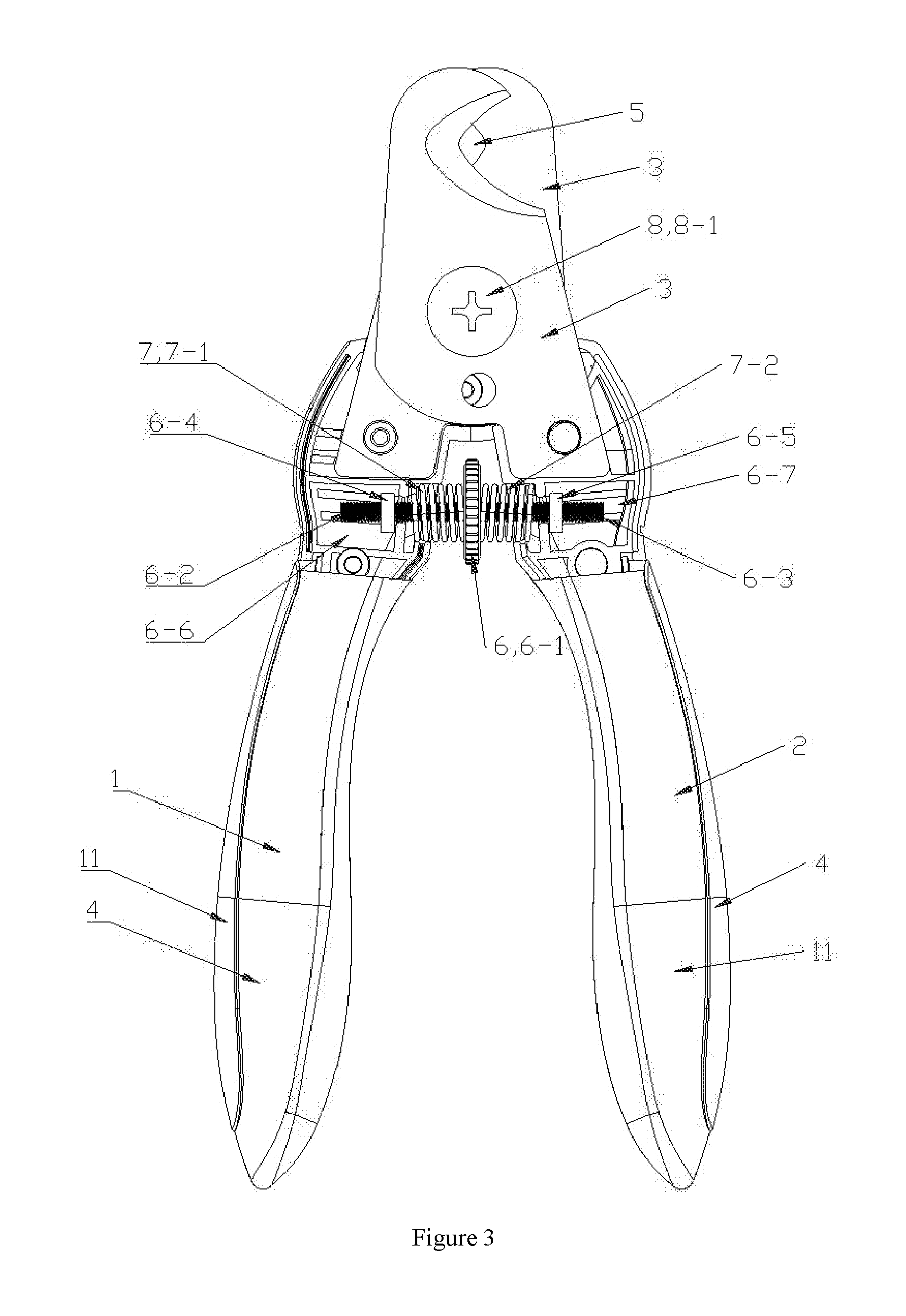
FIG. 3 is a schematic structural view of FIG. 1 after the turntable is rotated for adjustment;
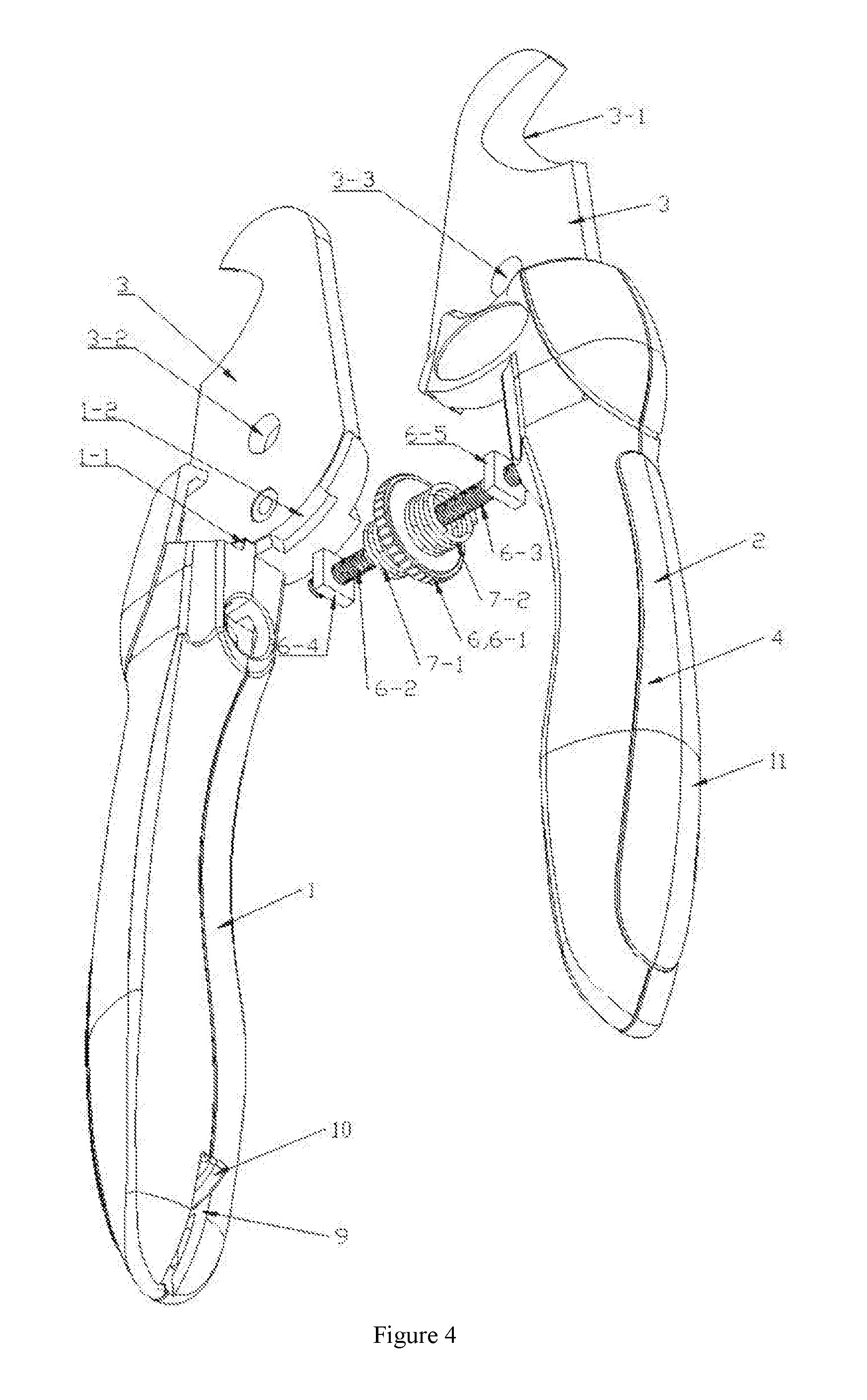
FIG. 4 is a schematic structural view of the assembly of FIG. 1;
FIG. 5 is a schematic side view of the half-cut structure of FIG. 2;
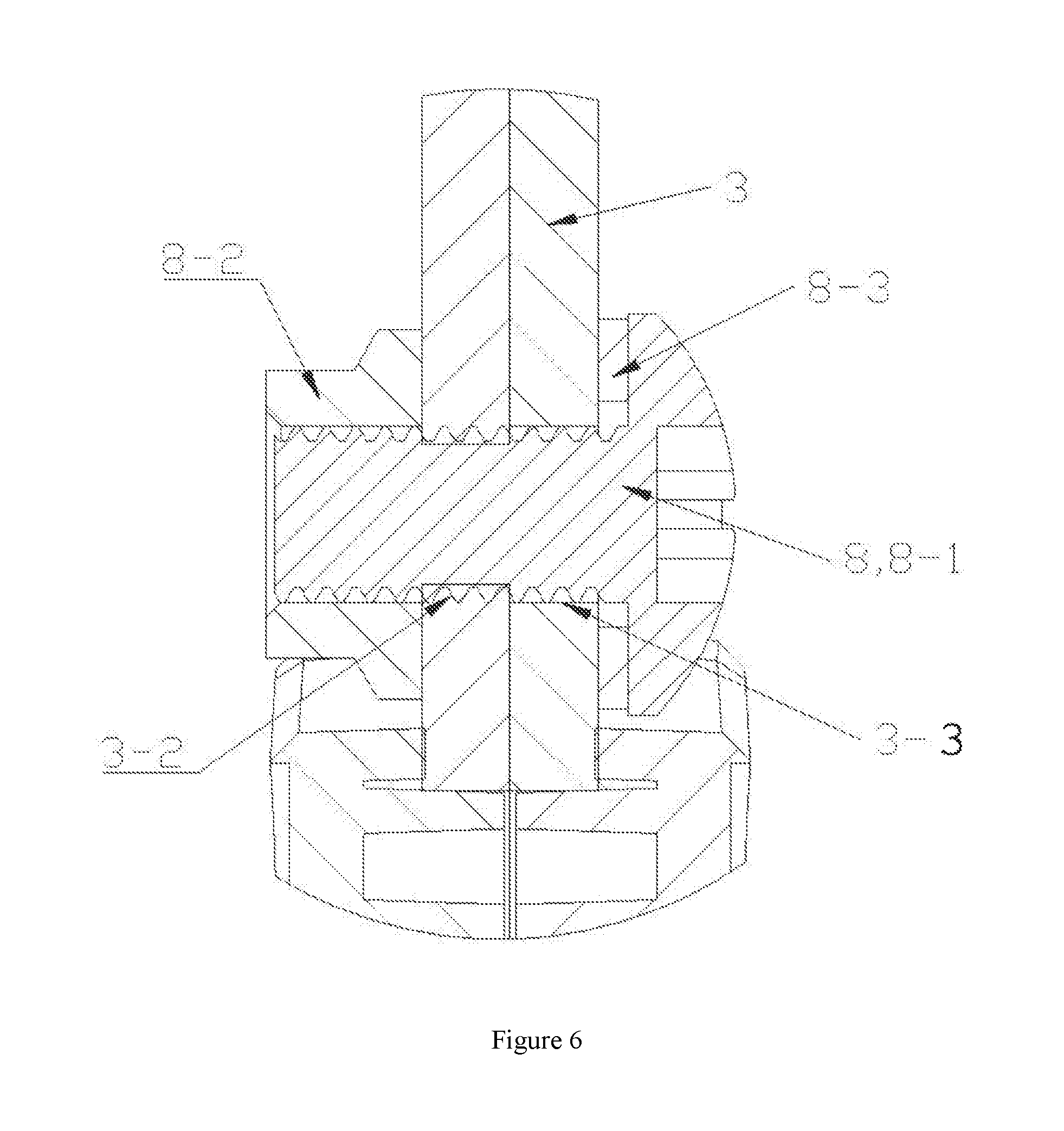
FIG. 6 is a schematic partial enlarged view of FIG. 5;
FIG. 7 is a schematic structural view of the front-and-rear partial assembly of FIG. 1;
FIG. 8 is a schematic structural view of Example 1 of the present invention when the first and second springs are a conical spring;
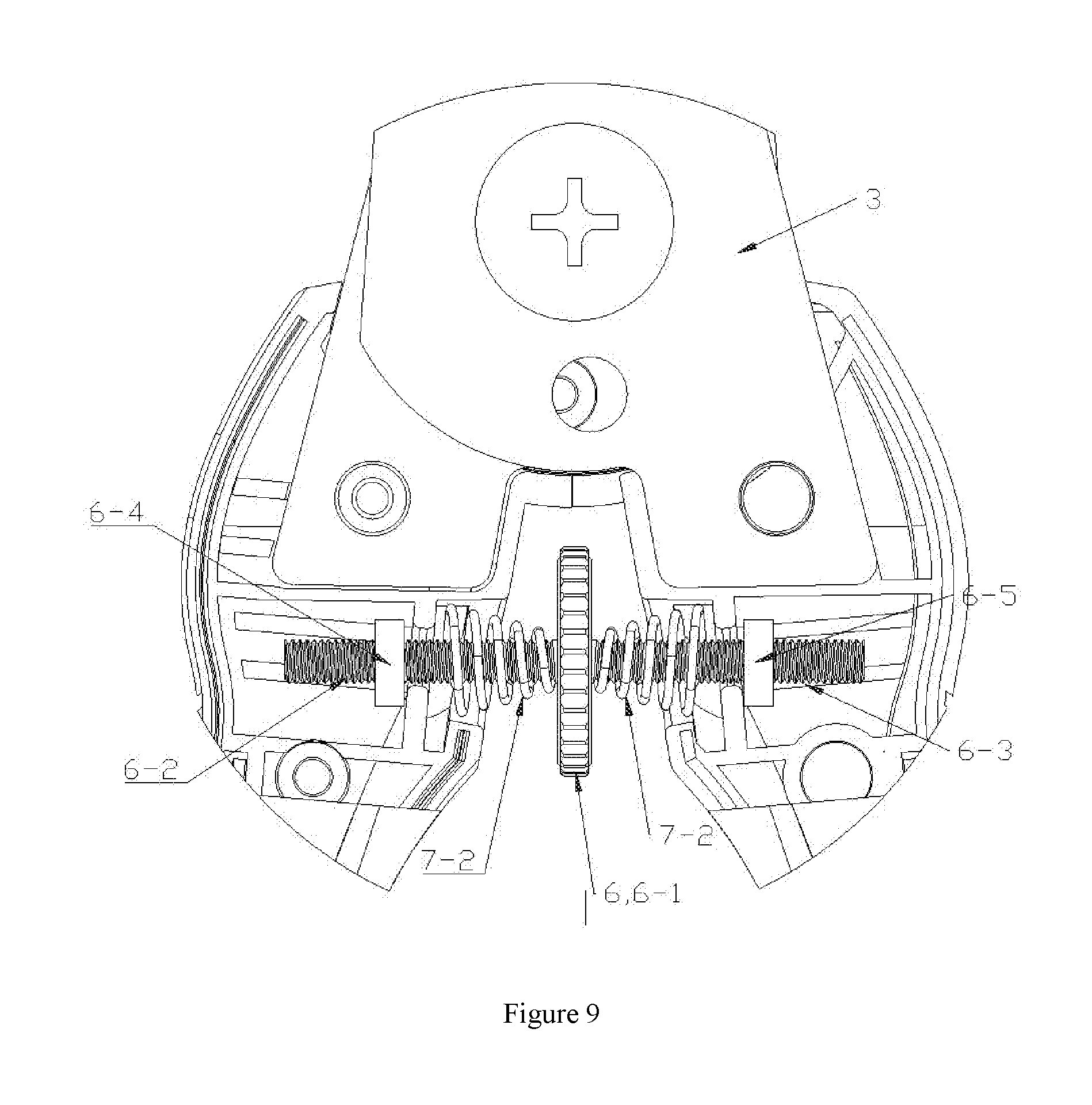
FIG. 9 is a schematic partial enlarged view of FIG. 8;
FIG. 10 is a schematic structural view of Example 2 of the present invention in the initial state;
FIGS. 11 and 12 are schematic structural views of the adjustment sheet in FIG. 10 when in adjustment; and
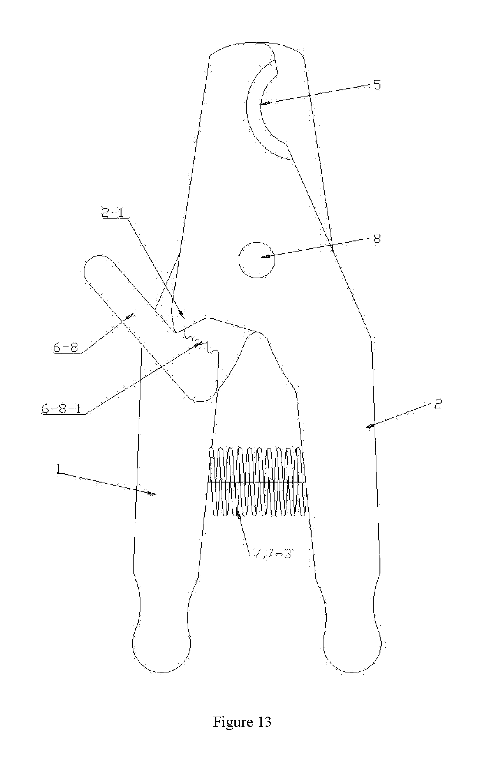
FIG. 13 is a schematic structural view of FIG. 10 when the blades are closed under an external force.
LIST OF REFERENCE NUMBERS
1. A first member; 1-1. a first limit lug; 1-2. a first limit groove;
2. a second member;
3. a blade portion; 3-1. a blade; 3-2. a screw hole; 3-3. a through hole;
4. a handle portion;
5. an initial trimming hole;
6. an adjustment mechanism; 6-1. a turntable; 6-2. a first screw; 6-3. a second screw; 6-4. a first limit block; 6-5. a second limit block; 6-6. a first mounting slot; 6-7. a second mounting slot; 6-8. an adjustment sheet; 6-8-1. a tooth groove;
7. a reset mechanism; 7-1. a first spring; 7-2. a second spring; 7-3. a reset member;
8. a pivot mechanism; 8-1. a pin; 8-2. a nut; 8-3. a gasket;
9. a receiving groove;
10. an abrasive rod; and
11. a flexible handpiece.
DETAILED DESCRIPTION OF PREFERRED EMBODIMENTS
Example 1
As shown in FIGS. 1-9, a pair of safe pet nail clippers is provided, comprising a first member 1 and a second member 2 correspondingly disposed and pivotally connected to each other, the first and second members 1, 2 respectively comprising a blade portion 3 and a handle portion 4; with blades 3-1 of the blade portions 3 of the first and second members 1, 2 provided in a concave shape, when the handle portions 4 of the first and second members 1, 2 are relatively opened to the maximum extent, an initial trimming hole 5 is formed between the concave blades 3-1 of the first and second members 1, 2, with the first and second members 1, 2 provided therebetween with an adjustment mechanism 6 for adjusting the relative opening of the handle portions 4 of the first and second members 1, 2 and the caliber of the initial trimming hole 5.
In this example, a specific structure of the adjustment mechanism 6 is as follows: The adjustment mechanism 6 comprises a turntable 6-1, a first screw 6-2 located on the left side of the turntable 6-1 and driven to rotate by the turntable 6-1, a second screw 6-3 located on the right side of the turntable 6-1 and driven to rotate by the turntable 6-1, a first limit block 6-4 screwed on the first screw 6-2, and a second limit block 6-5 screwed on the second screw 6-3, wherein the handle portions 4 of the first and second members 1, 2 are provided oppositely with a first mounting slot 6-6 and a second mounting slot 6-7, into which the first and second screws 6-2, 6-3 are inserted, with the threads on the two screws 6-2, 6-3 arranged in the reverse direction; the first and second limit blocks 6-4, 6-5 are respectively located in the first and second mounting slots 6-6, 6-7 and can move laterally relative to them, with notches of the first and second mounting slots 6-6, 6-7 smaller than the first and second limit blocks 6-4, 6-5; in order to prevent the first and second limit blocks 6-4 6-5 from being off the first and second screws 6-2, 6-3 due to over rotation, the first and second screws 6-2, 6-3 can be provided at the outer end with a stopper.
When the turntable 6-1 is rotated, it simultaneously drives the first and second screws 6-2, 6-3 to rotate, and the first and second limit blocks 6-4, 6-5 move axially close to or away from each other, so as to adjust the distance between the first and second limit blocks 6-4, 6-5, thus adjusting the relative opening of the handle portions 4 of the first and second members 1, 2 and the caliber of the initial trimming hole 5.
In this example, the first and second members 1, 2 are provided therebetween with a reset mechanism 7 for keeping the concave blades 3-1 of the first and second members 1, 2 in the position of the initial trimming hole 5.
A specific structure of the reset mechanism 7 is as follows: The reset mechanism 7 comprises a first spring 7-1 and a second spring 7-2, wherein the first spring 7-1 is sleeved on the first screw 6-2, with one end thereof abutting on the handle portion 4 of the first member 1 and the other end thereof abutting on the left side of the turntable 6-1, and the second spring 7-2 is sleeved on the second screw 6-3, with one end thereof abutting on the handle portion 4 of the second member 2 and the other end thereof abutting on the right side of the turntable 6-1. Wherein the first and second springs 7-1, 7-2 are preferably conical springs, the larger ends thereof respectively abutting on the handle portions 4 of the first and second members 1, 2, the smaller ends thereof respectively abutting on the left and right sides of the turntable 6-1. This conical spring can greatly reduce the damping generated during its cooperation with rotation of the turntable.
Another specific structure of the reset mechanism 7 is as follows: The reset mechanism 7 is a reset member 7-3 disposed between the handle portions 4 of the first and second members 1, 2. The reset member 7-3 may be a spring or an elastic sheet.
Example 2
As shown in FIGS. 10-13, a pair of safe pet nail clippers is provided, comprising a first member 1 and a second member 2 correspondingly disposed and pivotally connected to each other, the first and second members 1, 2 respectively comprising a blade portion 3 and a handle portion 4; with blades 3-1 of the blade portions 3 of the first and second members 1, 2 provided in a concave shape, when the handle portions 4 of the first and second members 1, 2 are relatively opened to the maximum extent, an initial trimming hole 5 is formed between the concave blades 3-1 of the first and second members 1, 2, with the first and second members 1, 2 provided therebetween with an adjustment mechanism 6 for adjusting the relative opening of the handle portions 4 of the first and second members 1, 2 and the caliber of the initial trimming hole 5.
In this example, a specific structure of the adjustment mechanism 6 is as follows: The adjustment mechanism 6 comprises an adjustment sheet 6-8, which is rotatably connected to the first member 1 and provided with multi-level tooth grooves 6-8-1; the second member 2 is provided with a convex tooth portion 2-1 matched with the tooth grooves 6-8-1; through engagement of the convex tooth portion 2-1 of the second member 2 with the different tooth grooves 6-8-1 of the adjustment sheet 6-8, the relative opening of the handle portions 4 of the first and second members 1, 2 and the caliber of the initial trimming hole 5 are adjusted.
In this example, the first and second members 1, 2 are provided therebetween with a reset mechanism 7 for keeping the concave blades 3-1 of the first and second members 1, 2 in the position of the initial trimming hole 5.
In this example, a specific structure of the reset mechanism 7 is as follows: The reset mechanism 7 is a reset member 7-3 disposed between the handle portions 4 of the first and second members 1, 2. The reset member 7-3 may be a spring or an elastic sheet.
In the above two examples, as shown in FIG. 4, the handle portion 4 of the first member 1 is provided with a first limit lug 1-1 and a first limit groove 1-2 at a connection portion thereof for mounting the blade portion 3, and the handle portion 4 of the second member 2 is provided with a second limit lug and a second limit groove at a connection portion thereof for mounting the blade portion 3, wherein the first limit lug 1-1 is embedded in the second limit groove and can slide relative to the same, and the second limit lug is embedded in the first limit groove 1-2 and can slide relative to the same.
In the above two examples, as shown in FIGS. 5 and 6, the blade portion 3 of the first member 1, provided with a screw hole 3-2, and the blade portion 3 of the second member 2, provided with a through hole 3-3, are pivoted by a pivot mechanism 8, which comprises a pin 8-1, a nut 8-2 and a corrugated gasket 8-3, with the pin 8-1 passing through the inner hole of the gasket 8-3, the through hole 3-3 and the screw hole 3-2 to pivot the first and second members 1, 2 and get them tightened with the nut 8-2. The above gasket 8-3 is arranged to make the blade portions 3 of the first and second members 1, 2 fit each other more tightly. The hole through which the bolt 8-1 is inserted is provided as the screw hole 3-2 on the blade portion 3 of the first member 1, so that the bolt 8-1 is respectively engaged with the screw hole 3-2 of the first member 1 and the nut 8-2, which makes the assembly more stable.
In the above two examples, as shown in FIGS. 2 and 4, a receiving groove 9, provided at the bottom of the handle portion 4 of the first member 1 or the second member 2, is provided inside with an abrasive rod 10 capable of being pulled out relative to the same, so that after a pet's nails are trimmed, the abrasive rod can be pulled out to wear the nails to prevent the pet from hurting a person or damaging an item by scratching since the nails are trimmed too sharp.
In the above two examples, the concave blade 3-1 is a concave blade, a U-shaped blade or a V-shaped blade.
In the above two examples, as shown in FIGS. 1-8, in order to improve the hand-held comfort of the pair of nail clippers, an elastic handpiece 11 is disposed on the outer sidewall of the handles 4 of the first and second members 1, 2.
When the present invention is used, the caliber of the initial trimming hole can be adjusted and controlled within a certain range by an adjustment mechanism according to the size of a pet's nails, so as to prevent the pet from being hurt due to excessive trimming and thus be safer to use.
What is mentioned above is only an embodiment of the present invention, and cannot limit the scope of protection of the present invention. In addition to the above examples, the present invention can also have other embodiments. Any technical solution based on equal substitution or equivalent alteration all falls within the scope of protection claimed by the present invention.
* * * * *
D00000
D00001
D00002
D00003
D00004
D00005
D00006
D00007
D00008
D00009
D00010
D00011
D00012

D00013
XML
uspto.report is an independent third-party trademark research tool that is not affiliated, endorsed, or sponsored by the United States Patent and Trademark Office (USPTO) or any other governmental organization. The information provided by uspto.report is based on publicly available data at the time of writing and is intended for informational purposes only.
While we strive to provide accurate and up-to-date information, we do not guarantee the accuracy, completeness, reliability, or suitability of the information displayed on this site. The use of this site is at your own risk. Any reliance you place on such information is therefore strictly at your own risk.
All official trademark data, including owner information, should be verified by visiting the official USPTO website at www.uspto.gov. This site is not intended to replace professional legal advice and should not be used as a substitute for consulting with a legal professional who is knowledgeable about trademark law.