Integrated gas sparger for an immersed membrane
Cumin , et al. J
U.S. patent number 10,173,175 [Application Number 15/156,532] was granted by the patent office on 2019-01-08 for integrated gas sparger for an immersed membrane. This patent grant is currently assigned to BL TECHNOLOGIES, INC.. The grantee listed for this patent is BL TECHNOLOGIES, INC.. Invention is credited to Reid Allyn Bayly, Jeffrey Ronald Cumin, Yongseck Hong.


| United States Patent | 10,173,175 |
| Cumin , et al. | January 8, 2019 |
Integrated gas sparger for an immersed membrane
Abstract
A gas sparger produces an intermittent flow of bubbles even if provided with a continuous gas flow. The sparger has a housing to collect a pocket of gas and a conduit to release some of the gas from the pocket when the pocket reaches a sufficient size. The housing is integrated with the potting head of a module. The conduit passes through the potting head.
| Inventors: | Cumin; Jeffrey Ronald (Hamilton, CA), Bayly; Reid Allyn (East York, CA), Hong; Yongseck (Burlington, CA) | ||||||||||
|---|---|---|---|---|---|---|---|---|---|---|---|
| Applicant: |
|
||||||||||
| Assignee: | BL TECHNOLOGIES, INC.
(Minnetonka, MN) |
||||||||||
| Family ID: | 45933441 | ||||||||||
| Appl. No.: | 15/156,532 | ||||||||||
| Filed: | May 17, 2016 |
Prior Publication Data
| Document Identifier | Publication Date | |
|---|---|---|
| US 20160256831 A1 | Sep 8, 2016 | |
Related U.S. Patent Documents
| Application Number | Filing Date | Patent Number | Issue Date | ||
|---|---|---|---|---|---|
| 12905701 | Oct 15, 2010 | 9364805 | |||
| Current U.S. Class: | 1/1 |
| Current CPC Class: | B01D 65/08 (20130101); B01F 15/024 (20130101); B01F 3/04241 (20130101); B01F 13/0255 (20130101); B01D 63/043 (20130101); B01D 61/18 (20130101); B01D 2313/21 (20130101); B01D 2321/185 (20130101); B01D 65/02 (20130101); B01D 2313/26 (20130101) |
| Current International Class: | B01D 63/02 (20060101); B01D 65/08 (20060101); B01D 61/18 (20060101); B01F 13/02 (20060101); B01F 3/04 (20060101); B01D 63/04 (20060101); B01D 65/02 (20060101) |
References Cited [Referenced By]
U.S. Patent Documents
| 1574783 | March 1926 | Beth |
| 3068655 | December 1962 | Murray et al. |
| 3246761 | April 1966 | Bryan et al. |
| 3592450 | July 1971 | Rippon |
| 3628775 | December 1971 | Mcconnell et al. |
| 3847508 | November 1974 | Mowen |
| 3898018 | August 1975 | Weis |
| 4169873 | October 1979 | Lipert |
| 4187263 | February 1980 | Lipert |
| 4356131 | October 1982 | Lipert |
| 4439316 | March 1984 | Kozima et al. |
| 4478211 | October 1984 | Haines et al. |
| 4569804 | February 1986 | Murphy |
| 4676225 | June 1987 | Bartera |
| 4752421 | June 1988 | Makino |
| 4789503 | December 1988 | Murphy |
| 4828696 | May 1989 | Makino et al. |
| 4906363 | March 1990 | Makino et al. |
| 4911838 | March 1990 | Tanaka |
| 4923614 | May 1990 | Engelbart |
| 5169781 | December 1992 | Nojima et al. |
| 5605653 | February 1997 | Devos |
| 5618431 | April 1997 | Kondo et al. |
| 5620891 | April 1997 | Drummond et al. |
| 5639373 | June 1997 | Mahendran et al. |
| 5783083 | July 1998 | Henshaw et al. |
| 5805653 | September 1998 | Hettiarachchi et al. |
| 6162020 | December 2000 | Kondo |
| 6245239 | June 2001 | Cote et al. |
| 6899812 | May 2005 | Cote et al. |
| 7017557 | March 2006 | Rumpf |
| 7022231 | April 2006 | Mahendran et al. |
| 7294255 | November 2007 | Kondo |
| 7867395 | January 2011 | Ekholm et al. |
| 7879229 | February 2011 | Phagoo et al. |
| 9358505 | June 2016 | Cumin |
| 9364805 | June 2016 | Cumin |
| 9433903 | September 2016 | Cumin |
| 2003/0178369 | September 2003 | Eguchi et al. |
| 2005/0006308 | January 2005 | Cote et al. |
| 2006/0201876 | September 2006 | Jordan et al. |
| 2007/0039888 | February 2007 | Ginzburg et al. |
| 2007/0166171 | July 2007 | Kondo |
| 2009/0194477 | August 2009 | Hashimoto |
| 2009/0215142 | August 2009 | Tsai et al. |
| 2009/0236280 | September 2009 | Morita et al. |
| 2009/0255872 | October 2009 | Busnot et al. |
| 2010/0300968 | December 2010 | Liu et al. |
| 2011/0100907 | May 2011 | Zha et al. |
| 1931419 | Mar 2007 | CN | |||
| 101448562 | Jun 2009 | CN | |||
| 0937494 | Aug 1999 | EP | |||
| 1119522 | Apr 2004 | EP | |||
| 1652572 | May 2006 | EP | |||
| 1897857 | Mar 2008 | EP | |||
| 996195 | Jun 1965 | GB | |||
| 5643438 | Oct 1981 | JP | |||
| S5643438 | Oct 1981 | JP | |||
| S62262185 | Nov 1987 | JP | |||
| S62268838 | Nov 1987 | JP | |||
| 638472 | Mar 1988 | JP | |||
| H01104396 | Apr 1989 | JP | |||
| H01111494 | Apr 1989 | JP | |||
| H04265128 | Sep 1992 | JP | |||
| H07185270 | Jul 1995 | JP | |||
| H07185271 | Jul 1995 | JP | |||
| H0810589 | Jan 1996 | JP | |||
| H08141566 | Jun 1996 | JP | |||
| 08257372 | Oct 1996 | JP | |||
| H08312161 | Nov 1996 | JP | |||
| H0938470 | Feb 1997 | JP | |||
| H09220569 | Aug 1997 | JP | |||
| 2003340250 | Dec 2003 | JP | |||
| 2004322100 | Nov 2004 | JP | |||
| 2006081979 | Mar 2006 | JP | |||
| 20010112874 | Dec 2001 | KR | |||
| 9706880 | Feb 1997 | WO | |||
| 9828066 | Jul 1998 | WO | |||
| 0021890 | Apr 2000 | WO | |||
| 2004050221 | Jun 2004 | WO | |||
| 2004056458 | Jul 2004 | WO | |||
| 2005105275 | Nov 2005 | WO | |||
| 2006029465 | Mar 2006 | WO | |||
| 2006066319 | Jun 2006 | WO | |||
| 2008001730 | Jan 2008 | WO | |||
| 2008144826 | Dec 2008 | WO | |||
| 2008153818 | Dec 2008 | WO | |||
| 2011028341 | Mar 2011 | WO | |||
Other References
|
Unofficial English Translation of Japanese Office Action issued in connection with Related JP Application No. 2015217626 dated Dec. 20, 2016. cited by applicant . Aintetsuku, English Abstract of JP 08312161 published Nov. 26, 1996. cited by applicant . Asahi Kasei Chemicals, English Abstract of JP2006081979 published Mar. 30, 2006. cited by applicant . Australian Patent Application No. 2011313970, Notice of Acceptance dated Jun. 23, 2016. cited by applicant . China Petrochemical Corp., English Abstract of CN1931419 published Mar. 21, 2007. cited by applicant . Chinese Patent Application No. 201180049733.9, Office Action dated May 26, 2014--Unofficial English Translation Available. cited by applicant . Cumin et al., U.S. Appl. No. 12/905,701, filed Oct. 15, 2010. cited by applicant . Hitachi Ltd., English Abstract of JP09-038470 published Feb. 10, 1997. cited by applicant . Infilco Degremont, "Cannon Mixer," obtained before Sep. 3, 2009. cited by applicant . Infilco Degremont, Infilco Cannon Mixer--Enhanced Sludge Mixing Technology, [online], [retrieved on Oct. 1, 2012]. Retrieved from Internet. cited by applicant . International Patent Application No. PCT/US2010/043926, International Preliminary Report on Patentability dated Mar. 6, 2012. cited by applicant . International Patent Application No. PCT/US2010/043926, International Search Report and Written Opinion dated Oct. 21, 2010. cited by applicant . International Patent Application No. PCT/US2011/054530, International Search Report and Written Opinion dated Apr. 27, 2012. cited by applicant . Kubota Copr, English Abstract of JP08141566 published Jun. 4, 1996. cited by applicant . Kubota Copr, English Abstract of JP09220569 published Aug. 26, 1997. cited by applicant . Kurita Water Ind Ltd, English Abstract of JP07185270 published Jul. 25, 1995. cited by applicant . Kurita Water Ind Ltd, English Abstract of JP07185271 published Jul. 25, 1995. cited by applicant . Kurita Water Ind Ltd, English Abstract of JP2004322100 published Nov. 18, 2004. cited by applicant . Mini-Ject Above-Grade Ejector Lift Station, [online], printed Jan. 28, 2009. Retrieved from the Internet. cited by applicant . Shinko Pfaudler Co Ltd, English Abstract of JP 01104396 published Apr. 21, 1989. cited by applicant . Shinko Pfaudler Co Ltd, English Abstract of JP01111494 published Apr. 28, 1989. cited by applicant . U.S. Appl. No. 12/905,701, Final Office Action dated Oct. 25, 2012. cited by applicant . U.S. Appl. No. 12/905,701, Non Final Rejection dated Jul. 8, 2014. cited by applicant . U.S. Appl. No. 12/905,701, Non-Final Office Action dated Jan. 23, 2015. cited by applicant . U.S. Appl. No. 12/905,701, Non-Final Office Action dated May 8, 2012. cited by applicant . U.S. Appl. No. 12/905,701, Notice of Allowance dated Feb. 16, 2016. cited by applicant . U.S. Appl. No. 12/905,701, Notice of Allowance dated Jul. 31, 2015. cited by applicant . U.S. Appl. No. 13/394,104, Non-Final Office Action dated Dec. 3, 2015. cited by applicant . U.S. Appl. No. 15/156,957, Non-Final Office Action dated Jul. 3, 2018. cited by applicant . Korean Patent Application No. 10-2017-7009907, Office Action dated Nov. 21, 2017--English Translation Available. cited by applicant . U.S. Appl. No. 15/156,957, Restriction Requirement dated Jan. 29, 2018. cited by applicant . Canadian Patent Application No. 2,773,180, Office Action dated Sep. 26, 2017. cited by applicant . Korean Patent Appln. No. 10-2017-7011198, Office Action dated Jan. 29, 2018. cited by applicant . Korean Patent Application No. 10-2018-7020343, Office Action dated Aug. 31, 2018--English Translation Available. cited by applicant. |
Primary Examiner: Zalasky; Katherine
Parent Case Text
RELATED APPLICATIONS
This application is a continuation of U.S. application Ser. No. 12/905,701 filed Oct. 15, 2010, which is incorporated herein by reference.
Claims
We claim:
1. A combination of a membrane module and an apparatus for providing gas bubbles in a liquid comprising, a) a housing defining a chamber and having an opening below the chamber allowing communication between the inside of the chamber and the outside of the chamber; and, b) a conduit extending from a first opening to a second opening, wherein the first opening is inside of the chamber and the second opening is outside of and above the chamber, the conduit having a first portion that extends downwards from the first opening to a low point of the conduit and a second portion that extends upwards from the low point of the conduit to the second opening in a direction from the first opening to the second opening, wherein, c) the chamber is adapted to hold a pocket of the gas above an interface between the gas pocket and the liquid, the interface having a variable elevation ranging from at least a lower boundary of the first opening in the conduit to an upper boundary of the low point of the conduit; d) the membrane module comprises a permeate cavity below a potting head of the membrane module; e) the second portion of the conduit passes through the potting head and the permeate cavity; f) the conduit having no third opening or tube in communication with the liquid outside of the chamber below the interface; and, g) wherein the potting head is a block of hardened resin into which membranes of the membrane module are potted.
2. The combination of claim 1, wherein the second opening of the conduit is at or above the top of the potting head.
3. The combination of claim 1 further comprising a gas supply conduit extending horizontally below the chamber and having an outlet to discharge gas into the chamber.
4. The combination of claim 1 further comprising a cap or diffuser above the potting head and over the second opening of the conduit.
5. The combination of claim 1 wherein the second opening has an area of 1-10 square cm.
6. The combination of claim 1 wherein the cross-sectional area of the second opening of the conduit is less than the horizontal cross-sectional area of the chamber by a factor of at least 10.
7. The combination of claim 1 having only one second opening.
8. The combination of claim 1 having a plurality of the potting heads, each with an associated housing and conduit, and further comprising a gas supply conduit extending horizontally below the chambers of the housings and having an outlet to discharge gas into each chamber.
Description
FIELD
This specification relates to a gas sparger and to gas scouring to inhibit fouling of a filtering membrane.
BACKGROUND
The following background discussion is not an admission that anything discussed below is citable as prior art or common general knowledge.
International PCT publication WO/2000/021890 describes an aeration system for a submerged membrane module that has a set of aerators connected to an air blower, valves and a controller adapted to alternately provide a higher rate of air flow and a lower rate of air flow in repeated cycles to individual aerators. In an embodiment, the air blower, valves and controller, simultaneously provide alternating air flows to two or more sets of aerators such that while the total system air flow is constant, allowing the blower to be operated at a constant speed, each aerator receives a flow of air that varies over time. In some embodiments, the flow of air to an aerator occurs in repeated cycles of short duration. Transient flow conditions result in the tank water which helps avoid dead spaces and assists in agitating the membranes. WO/2000/021890 is incorporated herein in its entirety by this reference to it.
INTRODUCTION
The following discussion is intended to introduce the reader to the more detailed discussion to follow, and not to limit or define any claim.
The air cycling process described in WO/2000/021890 has proven to be very effective at reducing the amount of air or other gas, and therefore energy, required to operate an immersed membrane system. It was noted in WO/2000/021890 that rapid valve movements result in very large bubbles being created for a brief period of time, and that these very large bubbles might help inhibit membrane fouling. However, it was also noted in WO/2000/021890 that creating these large bubbles required producing undesirable pressure spikes in the aeration system.
A burst of large bubbles can be used to break up a fouling film, gel or cake formed on a membrane, or accumulated around the membrane. Once the fouling structure is ruptured, less intense aeration at the end of a burst, or provided by other aerators between bursts, can continue to remove the foulants. The instantaneous gas flow rate during a burst may be 1.25 to 10 times that of conventional gas sparging. The duration of the burst of gas may be between 1 and 10 seconds. The frequency of the bursts may be from once every 2 seconds to once every 24 hours. Bursts may be created by temporarily increasing the gas pressure or flow of an existing aeration system, by a secondary gas sparging system or, as will be described below, by accumulating gas in a device configured to periodically release the accumulated gas.
A gas sparger, alternately called an aerator, will be described below that produces an intermittent flow of bubbles even when provided with a continuous gas flow. The flow of bubbles can be in the form of short bursts of very large bubbles. One or more gas spargers may be integrated or combined with a membrane module. Bubbles can be released in bursts within or at the sides, or both, of a bundle of hollow fiber membranes.
A potting head, or a permeate collector or gas conduit below a potting head, provides the top of a housing to collect a pocket of gas. A conduit passing through the potting head releases at least some of the gas from the pocket when the pocket reaches a sufficient size. Optionally, a cover or diffuser above the potting head and over an outlet from the conduit may direct the released gas or break up the released gas into smaller (though still large) bubbles or both. Even if fed with a continuous supply of gas, the sparger produces discrete periods of bubble flow, typically in the form of short bursts of large bubbles.
BRIEF DESCRIPTION OF THE FIGURES
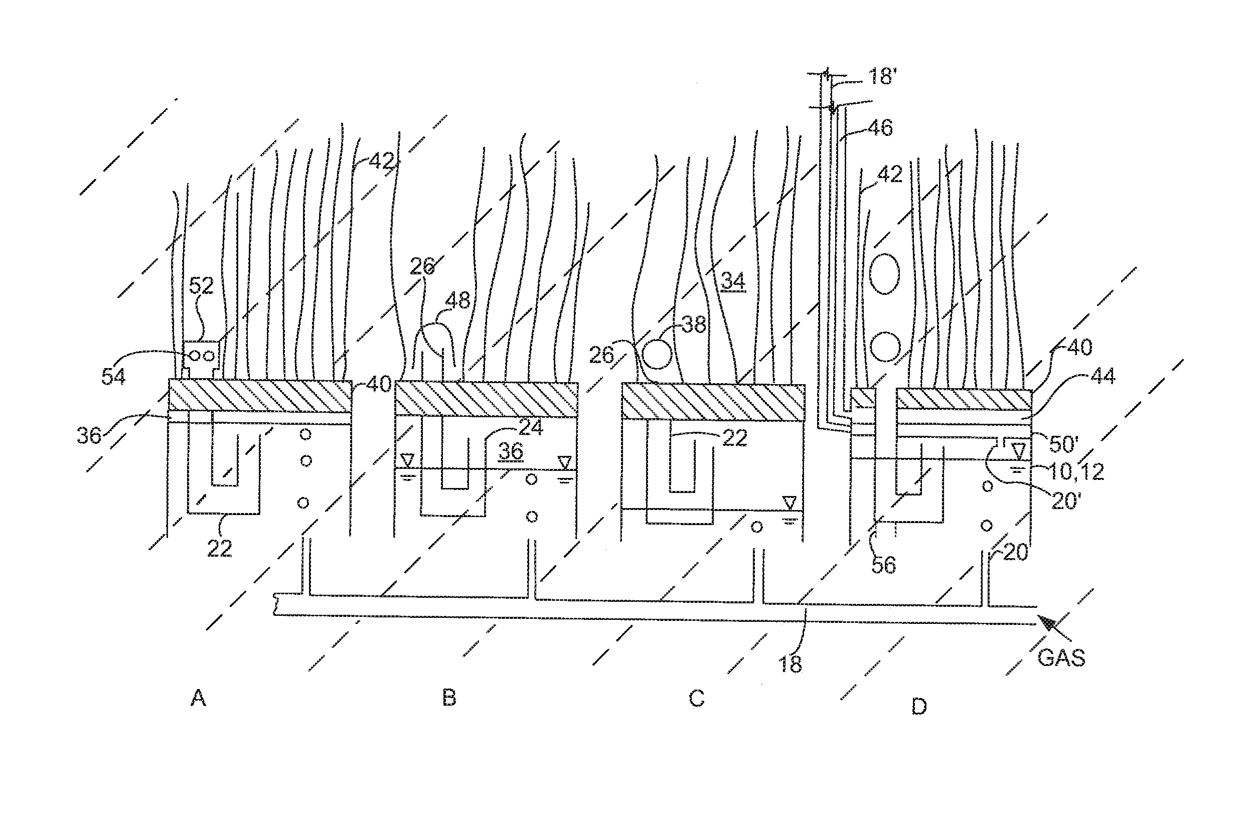
FIG. 1 shows a schematic side view of four spargers immersed in a liquid at various stages in an aeration process.
FIG. 2 shows an isometric view of an alternate conduit as in a sparger of FIG. 1.
DETAILED DESCRIPTION
FIG. 1 shows four spargers 10 integrated with the potting heads 40 of four membrane modules A, B, C and D. A potting head 40 may alternately be called a header. Each potting head 40 is typically a block of a potting material such as a hardened resin. The ends of a plurality of hollow fiber membranes 42 are potted into the potting head. In the case of modules A, B and C, the ends of the membranes 42 are plugged in the potting head 40. A second potting head (not shown) is provided at the other ends of the membranes 42 to withdraw permeate from the lumens of the membranes 42, for example by way of a suction applied to a permeate cavity in communication with the lumens of the membranes 42. In module D, the ends of the membranes 42 are open to a permeate cavity 44 which is in turn connected to a permeate withdrawal pipe 46. The upper ends of the membranes 42 in module D may be individually plugged and loose (not held in a potting head), plugged collectively into one or more upper potting heads, or potted in a second permeating potting head. The bottom of the potting head 40, or a mold for the potting head 40, or the bottom of the permeate cavity 44, or the bottom of a gas distribution conduit (not shown) below the permeate cavity 44, defines the top of a housing 12 below the potting head 40. The housing 12 also has walls extending below the potting head 40 to define an open bottomed plenum below the potting head 40.
A sparger 10 receives a flow of a gas, typically air, from a gas distribution pipe 18. The gas is discharged below or directly into the sparger 10 through one or more gas outlets 20 in communication with the distribution pipe 18. The distribution pipe 18 may be located near the bottom of sparger 10 as shown or at other elevations. For example, an alternative distribution pipe 18' may be connected to a gas conduit 50 formed by placing a horizontal wall below and parallel to the bottom of the potting head 40 or the bottom of the permeate cavity 44 as shown for module D. In the case of module D, the gas conduit 50 and permeate cavity 44 may each be connected to one or more adjacent modules such that the gas pipe 18 and permeate pipe 46 serve multiple modules without being directly connected to all of them. The gas distribution pipe 18 may also be located above the module, with a gas line dropping down to the sparger 10.
A sparger 10 has a discharge conduit 22 passing through the potting head 40. The discharge conduit has a first outlet 24 in communication with an area inside and near the top of the housing 12, and a second outlet 26 open to the outside of the housing 12 above the potting head 40. At least a portion of the conduit 22 extends downwards between the first opening 24 and the second opening 26. Another portion of conduit 22 extends upwards again before reaching the second opening 26. Gas leaving the housing 12 through the conduit 22 must pass through a low point in the conduit 22 between the first opening 24 and the second opening 26, as in the generally J or U shaped conduits 22 shown. Second opening 26 may have an area of 1 to 10 square cm or 3 to 6 square cm. The cross-sectional area of a pocket of gas in communication with a conduit 22 is preferably larger than the area of the second opening 26 by a factor of 10 or more, for example by a factor in the range of 20 to 35. If the cross-sectional area of a pocket of gas is small relative to the area of the second opening 26, then the low point of the conduit 22 and the walls of the housing 12 may be made lower to increase the volume of air in a pocket of gas in communication with the conduit 22.
A cap 48 or diffuser 52 may optionally be provided over the potting head 40 in communication with the second opening 26. The diffuser 52 may be, for example, a chamber with a plurality of holes 54 to cause a flow of air from the conduit 22 to break up into smaller bubbles. The cap 48 directs the flow of gas from the conduit downwards to the upper face of the potting head 40 or across the potting head 44 and may also cause gas flowing from the conduit 22 to break up into smaller bubbles. A solid cap 48 extending below the second opening 26 as shown may tend to trap a pocket of gas below the cap 48, which may interfere with the re-flooding of the conduit 22. If this occurs, holes may be provided in the cap 48 above the second opening, the lower edge of the cap 48 may be scalloped to provide horizontal openings near or above the height of the second opening 26, or the second opening may be lowered relative to the bottom of the cap 48, or the cap 48 may be raised relative to the second opening 26.
The operation of a sparger 10 immersed in a liquid 34 is illustrated schematically in FIG. 1 in that parts A, B, C and D each show a sparger 10 at four different points in a sequence that occurs in a single sparger 10 as a gas is fed into it. The sequence progresses from the conditions shown for A to B to C to D and then returns to condition A, and repeats for as long as a supply of a gas is provided to a sparger 10. In Part A of FIG. 5, a conduit 22 is flooded with liquid 34, although a pocket of gas 36 may be trapped in the housing 12. In Part B, the pocket of gas 36 grows in size as gas from distribution pipe 18 is collected in housing 12 and displaces liquid 34. Liquid 34 leaves the housing 12 through an opening to the bottom of the housing 12 and through conduit 22. In Part C, after the expanding pocket of gas 36 extends below the upper bound of a low point in conduit 12, a path is created for gas to flow from the pocket 36 and through the conduit 22, and gas is discharged outside of the housing 12, for example in bubbles 38. In Part D, gas continues to flow through the conduit 22, liquid 34 re-enters the housing 12 and the pocket 36 becomes smaller. Returning to Part A, the liquid 34 inside of the housing 12 eventually reaches the conduit 22, the conduit 22 floods, and gas flow through the conduit 22 stops. The process then repeats, producing discrete periods of gas discharge even when gas is supplied continuously.
Optionally, the conduit 22 may have a third opening, or an open tube 56 pointing downwards. Such an opening or tube 56 may help the conduit flood between the stages of Parts D and E but is typically not necessary. A third opening may also allow for an air-lift to be created in the part of the conduit from the third opening to the second outlet 26 to create a two phase gas-liquid discharge from the conduit 22. This may be useful if, for example, a module has a problem with liquid circulation near the top of the potting head 40. However, the inventors believe that creating a two phase flow also reduces the cleaning effect of the bubbles and so prefer a discharge that consists essentially of gas and any liquid that must be initially forced out of the conduit 22 to allow the gas to flow through the conduit.
The features of modules A, B, C and D, and the additional optional features described below, may be selected, mixed or combined together into any possible permutation or combination. The potting heads 40 may be round, square or rectangular in plan view for example. A second opening 26 may be located in the center, in plan view, of a round potting head, either as the only second opening 26 or in combination with a ring of additional second openings 26. A large module may have a large potting head that supports multiple spargers 10, for example as if the modules A, B, C and D were merged together to have a common potting head 44 but multiple spargers 10. A large potting head 44 with a plurality of conduits 22 may have the conduits distributed along the length of the potting head 44, across the width of the potting head 44, or both. A single conduit 22 may have two or more second openings 26, for example an opening on each side of a module or an opening in the middle and at each side of a module. FIG. 2 shows a further alternate conduit 22 having multiple second openings 26.
* * * * *
D00000
D00001
D00002
XML
uspto.report is an independent third-party trademark research tool that is not affiliated, endorsed, or sponsored by the United States Patent and Trademark Office (USPTO) or any other governmental organization. The information provided by uspto.report is based on publicly available data at the time of writing and is intended for informational purposes only.
While we strive to provide accurate and up-to-date information, we do not guarantee the accuracy, completeness, reliability, or suitability of the information displayed on this site. The use of this site is at your own risk. Any reliance you place on such information is therefore strictly at your own risk.
All official trademark data, including owner information, should be verified by visiting the official USPTO website at www.uspto.gov. This site is not intended to replace professional legal advice and should not be used as a substitute for consulting with a legal professional who is knowledgeable about trademark law.