Intraocular lens inserter
Auld , et al. J
U.S. patent number 10,172,706 [Application Number 15/072,023] was granted by the patent office on 2019-01-08 for intraocular lens inserter. This patent grant is currently assigned to Novartis AG. The grantee listed for this patent is NOVARTIS AG. Invention is credited to Jack Robert Auld, Matthew Braden Flowers, John Christopher Huculak, James Lescoulie, Matthew Douglas McCawley.


View All Diagrams
| United States Patent | 10,172,706 |
| Auld , et al. | January 8, 2019 |
Intraocular lens inserter
Abstract
Intraocular lens inserters and methods of use are disclosed. An example intraocular lens inserter may include an interior assembly having a movable member disposed therein. The movable member is movable in response to a pressure of a compressed gas. In response to the pressure of the compressed gas, the moveable member pressurizes a substantially incompressible fluid. The pressurized substantially incompressible fluid is used to advance a plunger. The plunger advances an intraocular lens through a lumen for insertion into an eye.
| Inventors: | Auld; Jack Robert (Laguna Niguel, CA), Huculak; John Christopher (Mission Viejo, CA), McCawley; Matthew Douglas (San Clemente, CA), Flowers; Matthew Braden (Aliso Viejo, CA), Lescoulie; James (Lake Forest, CA) | ||||||||||
|---|---|---|---|---|---|---|---|---|---|---|---|
| Applicant: |
|
||||||||||
| Assignee: | Novartis AG (Basel,
CH) |
||||||||||
| Family ID: | 56800314 | ||||||||||
| Appl. No.: | 15/072,023 | ||||||||||
| Filed: | March 16, 2016 |
Prior Publication Data
| Document Identifier | Publication Date | |
|---|---|---|
| US 20170119522 A1 | May 4, 2017 | |
Related U.S. Patent Documents
| Application Number | Filing Date | Patent Number | Issue Date | ||
|---|---|---|---|---|---|
| 62249185 | Oct 31, 2015 | ||||
| Current U.S. Class: | 1/1 |
| Current CPC Class: | A61F 2/167 (20130101); A61F 2/1672 (20130101) |
| Current International Class: | A61F 2/16 (20060101) |
| Field of Search: | ;623/6.12 |
References Cited [Referenced By]
U.S. Patent Documents
| 2547099 | April 1951 | Smoot |
| 4429421 | February 1984 | Levy |
| 4573998 | March 1986 | Mazzocco |
| 4615703 | October 1986 | Callahan et al. |
| 4619256 | October 1986 | Horn |
| 4634423 | January 1987 | Bailey et al. |
| 4699140 | October 1987 | Holmes et al. |
| 4715373 | December 1987 | Mazzocco et al. |
| 4726367 | February 1988 | Shoemaker |
| 4747404 | May 1988 | Jampel et al. |
| 4763650 | August 1988 | Hauser |
| 4765329 | August 1988 | Cumming et al. |
| 4822360 | April 1989 | Deacon |
| 4844065 | July 1989 | Faulkner |
| 4844093 | July 1989 | Jampel et al. |
| 4852566 | August 1989 | Callahan et al. |
| 4862885 | September 1989 | Cumming |
| 4880000 | November 1989 | Holmes et al. |
| 4906247 | March 1990 | Fritch |
| 4919130 | April 1990 | Stoy et al. |
| 4934363 | June 1990 | Smith et al. |
| 5007913 | April 1991 | Dulebohn et al. |
| 5064413 | November 1991 | McKinnon et al. |
| 5066297 | November 1991 | Cumming |
| 5098439 | March 1992 | Hill et al. |
| 5123905 | June 1992 | Kelman |
| 5190552 | March 1993 | Kelman |
| 5222972 | June 1993 | Hill et al. |
| 5304182 | April 1994 | Rheinish et al. |
| 5354333 | October 1994 | Kammann et al. |
| 5496328 | March 1996 | Nakajima et al. |
| 5562676 | October 1996 | Brady et al. |
| 5582613 | December 1996 | Brady et al. |
| 5582614 | December 1996 | Feingold |
| 5607433 | March 1997 | Polla et al. |
| 5616148 | April 1997 | Eagles et al. |
| 5629577 | May 1997 | Polla et al. |
| 5630821 | May 1997 | Klaas |
| 5643275 | July 1997 | Blake |
| 5643276 | July 1997 | Zaleski |
| 5693057 | December 1997 | Dusek |
| 5716364 | February 1998 | Makker et al. |
| 5772666 | June 1998 | Feingold et al. |
| 5772667 | June 1998 | Blake |
| 5776138 | July 1998 | Vidal et al. |
| 5800441 | September 1998 | Polla et al. |
| 5803925 | September 1998 | Yang et al. |
| 5807400 | September 1998 | Chambers et al. |
| 5810833 | September 1998 | Brady et al. |
| 5860984 | January 1999 | Chambers et al. |
| 5868751 | February 1999 | Feingold |
| 5873879 | February 1999 | Figueroa et al. |
| 5876406 | March 1999 | Wolf et al. |
| 5876407 | March 1999 | Makker et al. |
| 5876440 | March 1999 | Feingold |
| 5921989 | July 1999 | Deacon et al. |
| 5944725 | August 1999 | Cicenas et al. |
| 5947975 | September 1999 | Kikuchi et al. |
| 5947976 | September 1999 | Van Noy et al. |
| 6042587 | March 2000 | Polla et al. |
| 6162230 | December 2000 | Polla et al. |
| 6299618 | October 2001 | Sugiura |
| 6312433 | November 2001 | Butts et al. |
| 6334862 | January 2002 | Vidal et al. |
| 6336932 | January 2002 | Figueroa et al. |
| 6342058 | January 2002 | Portney |
| 6371960 | April 2002 | Heyman |
| 6387101 | May 2002 | Butts et al. |
| 6398789 | June 2002 | Capetan |
| 6428545 | August 2002 | Portney |
| 6468282 | October 2002 | Kikuchi et al. |
| 6491697 | December 2002 | Clark |
| 6500181 | December 2002 | Portney |
| 6500239 | December 2002 | Castellano |
| 6503275 | January 2003 | Cumming |
| 6506195 | January 2003 | Chambers et al. |
| 6537281 | March 2003 | Portney |
| 6537283 | March 2003 | Van Noy |
| 6540754 | April 2003 | Brady |
| 6554839 | April 2003 | Brady |
| 6558395 | May 2003 | Hjertman et al. |
| 6592591 | July 2003 | Polla et al. |
| 6607537 | August 2003 | Binder |
| 6629979 | October 2003 | Feingold |
| 6666871 | December 2003 | Kikuchi et al. |
| 6679891 | January 2004 | Makker |
| 6685740 | February 2004 | Figueroa et al. |
| 6712848 | March 2004 | Wolf et al. |
| 6723104 | April 2004 | Ott |
| 6733507 | May 2004 | McNicholas |
| 6858033 | February 2005 | Kobayashi |
| 6921405 | July 2005 | Feingold |
| 6923815 | August 2005 | Brady |
| 6976989 | December 2005 | Vincent |
| 7025782 | April 2006 | Kobayashi et al. |
| 7033366 | April 2006 | Brady |
| 7037312 | May 2006 | Kikuchi et al. |
| 7037328 | May 2006 | Vincent |
| 7131976 | November 2006 | Kobayashi |
| 7137994 | November 2006 | De Juan, Jr. |
| 7156854 | January 2007 | Brown et al. |
| 7156855 | January 2007 | Oda |
| 7276071 | October 2007 | Lin |
| 7279006 | October 2007 | Vincent |
| 7335209 | February 2008 | Meyer |
| RE40185 | March 2008 | Kikuchi et al. |
| 7348038 | March 2008 | Makker |
| 7422604 | September 2008 | Vaquero et al. |
| 7429263 | September 2008 | Vaquero et al. |
| 7458976 | December 2008 | Peterson |
| 7476229 | January 2009 | Meyer |
| 7476230 | January 2009 | Ohno et al. |
| 7645300 | January 2010 | Tsai |
| 7687097 | March 2010 | Makker |
| 7704258 | April 2010 | Feingold |
| 7717879 | May 2010 | Mansouri |
| 7740607 | June 2010 | Willis et al. |
| 7740636 | June 2010 | Lee |
| 7744603 | June 2010 | Zadno Azizi |
| 7867240 | January 2011 | Peterson |
| 7892283 | February 2011 | Shepherd |
| 7901414 | March 2011 | Tourrette |
| 7947049 | May 2011 | Vaquero |
| 7988701 | August 2011 | Vaquero et al. |
| 8021423 | September 2011 | Tanaka |
| 8048085 | November 2011 | Peterson |
| 8062360 | November 2011 | Pollock |
| 8080017 | December 2011 | Tanaka |
| 8114095 | February 2012 | Rathert |
| 8123719 | February 2012 | Edwards |
| 8123804 | February 2012 | Tanaka |
| 8142498 | March 2012 | Tsai |
| 8152817 | April 2012 | Tanaka |
| 8216629 | July 2012 | Mentak |
| 8225643 | July 2012 | Abboud et al. |
| 8246631 | August 2012 | Pynson |
| 8252053 | August 2012 | Pynson |
| 8308736 | November 2012 | Boukhny et al. |
| 8308799 | November 2012 | Chen |
| 8500681 | August 2013 | Gonnelli |
| 8574196 | November 2013 | Stammen et al. |
| 8579969 | November 2013 | Zacharias |
| 8617099 | December 2013 | Williamson |
| 8657835 | February 2014 | Boukhny et al. |
| 8668734 | March 2014 | Hildebrand et al. |
| 8721702 | May 2014 | Ramada et al. |
| 8758433 | June 2014 | Cole et al. |
| 8956408 | February 2015 | Smiley et al. |
| 8968396 | March 2015 | Matthews et al. |
| 8998983 | April 2015 | Auld |
| 9228273 | January 2016 | Keszler et al. |
| 9255665 | February 2016 | Brouillette et al. |
| 2001/0007075 | July 2001 | Hjertman et al. |
| 2001/0007942 | July 2001 | Kikuchi et al. |
| 2001/0015593 | August 2001 | Polla et al. |
| 2002/0193803 | December 2002 | Portney |
| 2003/0187455 | October 2003 | Kobayashi et al. |
| 2003/0212406 | November 2003 | Kobayashi et al. |
| 2003/0212407 | November 2003 | Kikuchi et al. |
| 2003/0216745 | November 2003 | Brady et al. |
| 2004/0059343 | March 2004 | Shearer et al. |
| 2004/0127911 | July 2004 | Figueroa et al. |
| 2004/0215207 | October 2004 | Cumming |
| 2004/0267359 | December 2004 | Makker |
| 2005/0033308 | February 2005 | Callahan |
| 2005/0171555 | August 2005 | Tran et al. |
| 2005/0222577 | October 2005 | Vaquero |
| 2005/0267403 | December 2005 | Landau et al. |
| 2005/0283162 | December 2005 | Stratas |
| 2005/0283163 | December 2005 | Portney |
| 2005/0283164 | December 2005 | Wu et al. |
| 2006/0085013 | April 2006 | Dusek |
| 2006/0129125 | June 2006 | Copa et al. |
| 2006/0142780 | June 2006 | Pynson et al. |
| 2006/0142781 | June 2006 | Pynson et al. |
| 2006/0167466 | July 2006 | Dusek |
| 2006/0184181 | August 2006 | Cole |
| 2006/0264971 | November 2006 | Akahoshi |
| 2006/0271063 | November 2006 | Sunada et al. |
| 2006/0287655 | December 2006 | Khuray et al. |
| 2006/0293694 | December 2006 | Futamura |
| 2007/0060925 | March 2007 | Pynson |
| 2007/0112355 | May 2007 | Salahieh et al. |
| 2007/0203502 | August 2007 | Makker |
| 2007/0270881 | November 2007 | Hishinuma et al. |
| 2007/0270945 | November 2007 | Kobayashi |
| 2008/0004610 | January 2008 | Miller et al. |
| 2008/0027460 | January 2008 | Kobayashi |
| 2008/0027461 | January 2008 | Vaquero et al. |
| 2008/0033449 | February 2008 | Cole et al. |
| 2008/0039862 | February 2008 | Tran |
| 2008/0058830 | March 2008 | Cole et al. |
| 2008/0086146 | April 2008 | Ishii |
| 2008/0097459 | April 2008 | Kammerlander |
| 2008/0097460 | April 2008 | Boukhny et al. |
| 2008/0097461 | April 2008 | Boukhny et al. |
| 2008/0114203 | May 2008 | Crank |
| 2008/0119783 | May 2008 | Green |
| 2008/0147080 | June 2008 | Pynson |
| 2008/0147081 | June 2008 | Pynson |
| 2008/0147082 | June 2008 | Pynson |
| 2008/0154361 | June 2008 | Pynson et al. |
| 2008/0171968 | July 2008 | Stout |
| 2008/0208176 | August 2008 | Loh |
| 2008/0255579 | October 2008 | Wollenhaupt |
| 2008/0269770 | October 2008 | Pynson et al. |
| 2009/0005788 | January 2009 | Rathert |
| 2009/0018548 | January 2009 | Charles |
| 2009/0024136 | January 2009 | Martin et al. |
| 2009/0030425 | January 2009 | Smiley et al. |
| 2009/0036898 | February 2009 | Ichinohe et al. |
| 2009/0043313 | February 2009 | Ichinohe et al. |
| 2009/0112222 | April 2009 | Barrows |
| 2009/0198247 | August 2009 | Ben Nun |
| 2009/0204122 | August 2009 | Ichinohe et al. |
| 2009/0234366 | September 2009 | Tsai et al. |
| 2009/0248031 | October 2009 | Ichinohe et al. |
| 2009/0270876 | October 2009 | Hoffmann et al. |
| 2009/0292293 | November 2009 | Bogaert et al. |
| 2009/0318933 | December 2009 | Anderson |
| 2010/0010498 | January 2010 | Biddle et al. |
| 2010/0057095 | March 2010 | Khuray et al. |
| 2010/0076450 | March 2010 | Yoshida |
| 2010/0082037 | April 2010 | Kobayashi et al. |
| 2010/0087832 | April 2010 | Seyboth |
| 2010/0094309 | April 2010 | Boukhny et al. |
| 2010/0106160 | April 2010 | Tsai |
| 2010/0121340 | May 2010 | Downer |
| 2010/0125278 | May 2010 | Wagner |
| 2010/0125279 | May 2010 | Karakelle |
| 2010/0160926 | June 2010 | Artsyukhovich |
| 2010/0161049 | June 2010 | Inoue |
| 2010/0185206 | July 2010 | Ichinohe et al. |
| 2010/0204704 | August 2010 | Davies et al. |
| 2010/0204705 | August 2010 | Brown et al. |
| 2010/0217273 | August 2010 | Someya et al. |
| 2010/0217274 | August 2010 | Lee et al. |
| 2010/0228260 | September 2010 | Callahan et al. |
| 2010/0228261 | September 2010 | Feingold et al. |
| 2010/0256651 | October 2010 | Jani et al. |
| 2010/0280521 | November 2010 | Vaquero et al. |
| 2010/0286704 | November 2010 | Ichinohe et al. |
| 2010/0305577 | December 2010 | Muchhala |
| 2010/0312254 | December 2010 | Downer et al. |
| 2011/0046633 | February 2011 | Pankin |
| 2011/0046634 | February 2011 | Rathert |
| 2011/0046635 | February 2011 | Pankin |
| 2011/0082463 | April 2011 | Inoue |
| 2011/0098717 | April 2011 | Inoue |
| 2011/0144653 | June 2011 | Pankin |
| 2011/0152872 | June 2011 | Seyboth et al. |
| 2011/0152873 | June 2011 | Shepherd |
| 2011/0172676 | July 2011 | Chen |
| 2011/0190777 | August 2011 | Hohl |
| 2011/0213380 | September 2011 | Han |
| 2011/0224677 | September 2011 | Niwa et al. |
| 2011/0245840 | October 2011 | Seyboth et al. |
| 2011/0264101 | October 2011 | Inoue |
| 2011/0264102 | October 2011 | Cole et al. |
| 2011/0264103 | October 2011 | Cole et al. |
| 2011/0270264 | November 2011 | Shoji et al. |
| 2011/0288557 | November 2011 | Kudo et al. |
| 2011/0295264 | December 2011 | Cole et al. |
| 2011/0313425 | December 2011 | Han |
| 2012/0016374 | January 2012 | Han |
| 2012/0016375 | January 2012 | Peterson |
| 2012/0022547 | January 2012 | Hilderbrand et al. |
| 2012/0022548 | January 2012 | Zacharias |
| 2012/0071888 | March 2012 | Putallaz et al. |
| 2012/0130390 | May 2012 | Davies |
| 2012/0158007 | June 2012 | Brown et al. |
| 2012/0165824 | June 2012 | Tsai |
| 2012/0245591 | September 2012 | Matthews |
| 2012/0253356 | October 2012 | Niwa et al. |
| 2012/0289969 | November 2012 | Seyboth et al. |
| 2012/0289970 | November 2012 | Pynson |
| 2012/0296264 | November 2012 | Boukhny et al. |
| 2013/0012956 | January 2013 | Mirlay |
| 2013/0035939 | February 2013 | Gilbert |
| 2013/0041382 | February 2013 | Ben Nun |
| 2013/0197531 | August 2013 | Boukhny et al. |
| 2013/0197532 | August 2013 | Boukhny et al. |
| 2013/0281927 | October 2013 | Jennings et al. |
| 2014/0200590 | July 2014 | Chen |
| 2015/0088149 | March 2015 | Auld |
| 2015/0282928 | October 2015 | Auld et al. |
| 2015/0342726 | December 2015 | Deacon et al. |
| 2016/0015511 | January 2016 | Auld et al. |
| 2858485 | Jun 2013 | CA | |||
| 0174129 | Mar 1986 | EP | |||
| 0477466 | Apr 1992 | EP | |||
| 0937466 | Aug 1999 | EP | |||
| 1175187 | Jan 2002 | EP | |||
| 1344503 | Sep 2003 | EP | |||
| 1481652 | Dec 2004 | EP | |||
| 1144031 | Oct 2005 | EP | |||
| 1736118 | Dec 2006 | EP | |||
| 1857075 | Nov 2007 | EP | |||
| 2074962 | Jul 2009 | EP | |||
| 2324797 | May 2011 | EP | |||
| 2368526 | Sep 2011 | EP | |||
| 2491902 | Aug 2012 | EP | |||
| 2502603 | Sep 2012 | EP | |||
| 1539065 | Dec 2012 | EP | |||
| 1748811 | Dec 2012 | EP | |||
| 2178464 | Aug 2013 | EP | |||
| 2560578 | Jun 2016 | EP | |||
| 3075353 | Oct 2016 | EP | |||
| 3122286 | Feb 2017 | EP | |||
| 3207374 | Sep 1991 | JP | |||
| 2004261263 | Sep 2004 | JP | |||
| 2007215990 | Aug 2007 | JP | |||
| 2008500876 | Jan 2008 | JP | |||
| 2016049321 | Apr 2016 | JP | |||
| 2386423 | Apr 2010 | RU | |||
| 199637152 | Nov 1996 | WO | |||
| 200164147 | Sep 2001 | WO | |||
| 2007098622 | Sep 2007 | WO | |||
| 2007112130 | Oct 2007 | WO | |||
| 2010028873 | Mar 2010 | WO | |||
| 2011133823 | Oct 2011 | WO | |||
| 2012006616 | Jan 2012 | WO | |||
| 12086797 | Jun 2012 | WO | |||
| 13076067 | May 2013 | WO | |||
| 2013086612 | Jun 2013 | WO | |||
| 2015154049 | Dec 2013 | WO | |||
| 2013184727 | Feb 2014 | WO | |||
| 2014149459 | Sep 2014 | WO | |||
| 15144890 | Oct 2015 | WO | |||
| 2015144870 | Oct 2015 | WO | |||
| 2015144890 | Oct 2015 | WO | |||
| 2015154049 | Oct 2015 | WO | |||
| 2014089250 | Jun 2016 | WO | |||
| 2016208725 | Dec 2016 | WO | |||
| 17047715 | Mar 2017 | WO | |||
Other References
|
EP0477466, Dated Apr. 1, 1992, Adatomed Pharmazeutische, Abstract only. cited by applicant . RU2386423 with English translation. cited by applicant . 2016049321 JP Abstract translation only. cited by applicant . WO2012086797 Abstract translation only. cited by applicant . WO2017047715 Abstract translation only. cited by applicant. |
Primary Examiner: Tyson; Melanie
Parent Case Text
CROSS-REFERENCE TO RELATED APPLICATION
This application claims the benefit of U.S. Provisional Application No. 62/249,185, filed Oct. 31, 2015, the entire contents of which are incorporated herein by reference.
Claims
What is claimed is:
1. An intraocular lens inserter comprising: an inserter body defining a first interior cavity; a compressed gas container coupled to the inserter body; an assembly disposed within the first interior cavity and moveable within the first interior cavity relative to the inserter body, the assembly comprising: a housing; a second interior cavity formed within the housing; and a moveable member disposed within the second interior cavity and moveable therein relative to the housing, the moveable member dividing the second interior cavity into a first portion adapted to receive a compressed gas from the compressed gas container and a second portion configured to contain a substantially incompressible fluid, the moveable member configured to impart a pressure from the compressed gas to the substantially incompressible fluid; and a plunger, the plunger movable in response to pressure imparted by the substantially incompressible fluid.
2. The intraocular lens inserter of claim 1, further comprising an actuator moveable between an unactuated position and an actuated position, the actuator operable to displace the assembly between an initial position and a displaced position relative to the compressed gas container in response to movement of the actuator to the actuated position.
3. The intraocular lens inserter of claim 2, further comprising a resilient member disposed between the housing and the compressed gas container, the resilient member configured to apply a biasing force that urges the assembly towards the initial position when the actuator is moved into the actuated position.
4. The intraocular lens inserter of claim 1, wherein the assembly further comprises a piercing member configured to pierce the compressed gas container.
5. The intraocular lens inserter of claim 4, wherein the piercing member is configured to pierce the compressed gas container in response to displacement of the assembly relative to the compressed gas container.
6. The intraocular lens inserter of claim 1, further comprising an orifice, wherein the assembly further comprises a valve body comprising: an aperture; and a needle valve receivable into the orifice.
7. The intraocular lens inserter of claim 6, wherein displacement of the assembly within the inserter body displaces the needle valve relative to the orifice resulting in fluid communication between the second portion of the second interior cavity and the orifice via the aperture.
8. The intraocular lens inserter of claim 7, further comprising a plunger housing, the plunger housing forming a third interior cavity configured to receive the plunger, wherein the third interior cavity is in fluid communication with the orifice, and wherein the substantially incompressible fluid is flowable through the aperture and the orifice to apply pressure to the plunger to displace the plunger within the third interior cavity in response to displacement of the assembly within the inserter body.
9. The intraocular lens inserter of claim 6, wherein the needle valve comprises a tapered surface, and wherein displacement of the needle valve within the orifice forms a gap between the tapered surface of the needle valve and the orifice that varies with an amount by which the needle valve is moved relative to the orifice.
10. An intraocular lens inserter comprising: an inserter body defining a first interior cavity; a pressurized gas canister disposed in the first interior cavity; an assembly disposed in the first interior cavity and moveable therein relative to the inserter body, the assembly comprising: a first housing defining a second interior cavity; a valve body disposed at a first end of the first housing; a moveable member disposed in the second interior cavity and movable relative to the first housing; and a piercing member disposed at a second end of the first housing, opposite the first end; an actuator pivotably coupled to the inserter body, the actuator comprising a lever arm that engages the assembly, the actuator operable to displace the assembly within the inserter body when the actuator is pivoted relative to the inserter body.
11. The intraocular lens inserter of claim 10, wherein the piercing member is configured to pierce the pressurized gas canister when the assembly is displaced within the inserter body.
12. The intraocular lens inserter of claim 11, wherein the assembly further comprises a passage operable to communicate pressurized gas released from the pressurized gas canister into the second interior cavity.
13. The intraocular lens inserter of claim 10, wherein the moveable member is displaceable within the second interior cavity in response to pressurized gas released from the pressurized gas canister.
14. The intraocular lens inserter of claim 13, wherein the assembly further comprises a passage between the first portion and the pressurized gas canister, and wherein pressurized gas released from the pressurized gas canister is communicated to the first portion via the passage.
15. The intraocular lens inserter of claim 10, wherein the moveable member divides the second interior cavity into a first portion and a second portion, and wherein a substantially incompressible fluid is disposed in the second portion.
16. The intraocular lens inserter of claim 15, further comprising: a plunger housing; a plunger received into a chamber formed in the plunger housing; and an orifice formed in the plunger housing, the orifice in fluid communication with the chamber formed in the plunger housing; wherein the valve body comprises a needle valve removably received into the orifice, the needle valve displaceable from the orifice in response to a displacement of the assembly within the inserter body, wherein displacement of the needle valve from the orifice provides fluid communication between a substantially incompressible fluid contained within the second portion of the second interior cavity and the chamber formed in the plunger housing.
17. The intraocular lens inserter of claim 16, wherein the assembly is moveable between a first position in which the needle valve is seated within the orifice and a second position in which the needle valve is unseated from the orifice and the piercing member penetrates the pressurized gas container canister to release the pressurized gas into the first portion in response to articulation of the actuator from a third position to a fourth position.
18. The intraocular lens inserter of claim 17, wherein the movable member is displaceable within the second interior cavity and operable to transmit the pressure of the pressurized gas within the first portion to the substantially incompressible fluid contained in the second portion in response to the pressure of the pressurized gas, wherein the substantially incompressible fluid is flowable into the chamber via the orifice in response to displacement of the moveable member, and wherein the plunger is movable within the chamber in response to pressure transmitted thereto by the substantially incompressible fluid.
19. The intraocular lens inserter of claim 17, further comprising a biasing member disposed between the assembly and the pressurized gas canister, and wherein the biasing member applies a biasing force when the assembly is displaced from the first position that urges the assembly back into the first position.
20. The intraocular lens inserter of claim 16, wherein the needle valve comprises a tapered surface, wherein a gap is formed between the tapered surface of the needle valve and the orifice when the needle valve is unseated from the orifice, and wherein a size of the gap is altered by the amount by which the needle valve is displaced relative to the orifice.
21. The intraocular lens inserter of claim 20, wherein the size of the gap is altered in response to an amount by which the actuator is pivoted relative to the inserter body.
Description
TECHNICAL FIELD
The present disclosure relates to systems, devices, and methods for inserting an intraocular lens into an eye and, particularly, to utilizing a compressed fluid to insert an intraocular lens into an eye.
SUMMARY
A first aspect of the present disclosure may include an intraocular lens inserter having an inserter body defining a first interior cavity, a compressed gas container coupled to the inserter body, an assembly disposed within the cavity and moveable within the first interior cavity relative to the inserter body, and a plunger. The assembly may include a housing, a second interior cavity formed within the housing, and a moveable member disposed within the second interior cavity and moveable therein relative to the housing. The moveable member may divide the second interior cavity into a first portion adapted to receive a compressed gas from the compressed gas container and a second portion configured to contain a substantially incompressible fluid. The moveable member may be configured to impart a pressure from the pressurized gas to the substantially incompressible fluid contained. The plunger may be movable in response to pressure imparted by the substantially incompressible fluid.
According to another aspect, the disclosure describes an intraocular lens inserter that may include an inserter body defining a first interior cavity, a pressurized gas canister disposed in the first interior cavity, an assembly disposed in the first interior cavity and moveable therein relative to the inserter body, and an actuator pivotably coupled to the inserter body. The assembly may include a first housing defining a second interior cavity, a valve body disposed at a first end of the first housing, a moveable member disposed in the second interior cavity and movable relative to the first housing, and a piercing member disposed at a second end of the first housing that is opposite the first end. The actuator may include a lever arm that engages the assembly. The actuator may be operable to displace the assembly within the inserter body when the actuator is pivoted relative to the inserter body.
The various aspects may include one or more of the following features. An actuator may be moveable between an unactuated position and an actuated position. The actuator may be operable to displace the interior assembly between an initial position and a displaced position relative to the compressed gas canister in response to movement of the actuator to the actuated position. A resilient member may be disposed between the housing and the compressed gas canister. The resilient member may be configured to apply a biasing force that urges the assembly towards the initial position when the actuator is moved into the actuated position. The assembly may include a piercing member configured to pierce the compressed gas container. The piercing member may be configured to pierce the compressed gas container in response to displacement of the assembly relative to the gas canister. The intraocular lens inserter may include an orifice, and the assembly may include a valve body. The valve body may include an aperture and a needle valve receivable into the orifice. Displacement of assembly within the inserter body may displace the needle valve relative to the orifice to provide in fluid communication between the second portion of the second interior cavity and the orifice via the aperture.
The various aspects may also include one or more of the following features. a plunger housing may also be included. The plunger housing may form a third interior cavity configured to receive the plunger. The third interior cavity may be in fluid communication with the orifice, and the substantially incompressible fluid may flow through the aperture and the orifice to apply pressure to the plunger to displace the plunger within the third interior cavity in response to displacement of the assembly within the inserter body. The needle valve may include a tapered surface, and displacement of the needle valve within the orifice may form a gap between the tapered surface of the needle valve and the orifice that varies with an amount by which the needle valve is moved relative to the orifice.
The various aspects may further include one or more of the following features. The piercing member may be configured to pierce the pressurized gas canister when the assembly is displaced within the inserter body. The assembly may include a passage operable to communicate compressed gas released from the compressed gas canister into the second interior cavity. The moveable member may be displaceable within the second interior cavity in response to pressurized gas released from the pressurized gas canister. The moveable member may divide the interior cavity into a first portion and a second portion, and a substantially incompressible fluid may be disposed in the second portion. The assembly may include a passage between the first portion and the compressed gas canister, and wherein compressed gas released from the compressed gas canister may be communicated to the first portion via the passageway.
The various aspects may include one or more of the following features. An intraocular lens inserter may also include a plunger housing, a plunger received into a chamber formed in the plunger housing, and an orifice formed in the plunger housing. The orifice may be in fluid communication with the chamber formed in the plunger housing. The valve body may include a needle valve removably received into the orifice. The needle valve may be displaceable from the orifice in response to a displacement of the assembly within the inserter body. Displacement of the needle valve from the orifice may provide fluid communication between a substantially incompressible fluid contained within the second portion of the second interior cavity and the chamber formed in the plunger housing. The assembly may be moveable between a first position in which the needle valve is seated within the orifice and a second position in which the needle valve is unseated from the orifice and the piercing member penetrates the gas canister to release the compressed gas into the first portion in response to articulation of the actuator from a third position to a fourth position. The movable member may be displaceable within the second interior cavity and operable to transmit the pressure of the compressed gas within the first portion to the substantially incompressible fluid contained in the second portion in response to the pressure of the compressed gas. The substantially incompressible fluid may be flowable into the chamber via the orifice in response to displacement of the moveable member, and the plunger may be movable within the chamber in response to pressure transmitted thereto by the substantially incompressible fluid. A biasing member may be disposed between the assembly and the compressed gas canister. The biasing member may apply a biasing force when the assembly is displaced from the first position that urges the assembly back into the first position. The needle valve may include a tapered surface, and a gap may be formed between the tapered surface of the needle valve and the orifice when the needle valve is unseated from the orifice. A size of the gap may be altered by the amount by which the needle valve is displaced relative to the orifice. The size of the gap may be altered in response to an amount by which the actuator is pivoted relative to the inserter body.
It is to be understood that both the foregoing general description and the following detailed description are exemplary and explanatory in nature and are intended to provide an understanding of the present disclosure without limiting the scope of the present disclosure. In that regard, additional aspects, features, and advantages of the present disclosure will be apparent to one skilled in the art from the following detailed description.
BRIEF DESCRIPTION OF THE DRAWINGS
FIG. 1 is an example intraocular lens inserter.
FIG. 2 shows a top vie of the example intraocular lens inserter of FIG. 1.
FIG. 3 shows a side view of the example intraocular lens inserter shown in FIG. 1.
FIG. 4 is a cross-sectional view of the example intraocular lens inserter shown in FIG. 1.
FIG. 5A is a partial cross-sectional view of an example intraocular lens inserter that includes a valve body, an interior assembly of the example intraocular lens inserter being in an initial, unarticulated position.
FIG. 5B also shows a partial cross-sectional view of an example intraocular lens inserter that includes a bulkhead, an interior assembly of the example intraocular lens inserter being in an initial, unarticulated position.
FIGS. 6A and 6B are detail views of the partial cross-sectional view of the example intraocular lens inserter of FIG. 5 with the interior assembly in an articulated position.
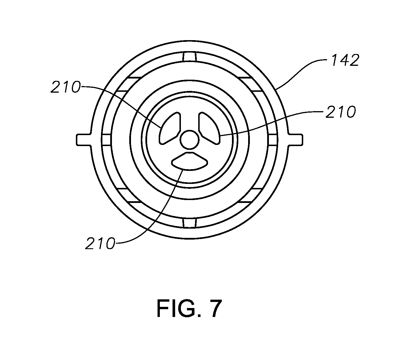
FIG. 7 is a back view of an example valve body.
FIG. 8 is a perspective view of an example intraocular lens inserter with a portion of thereof removed.
FIG. 9 is a perspective view of an example lever lock.
FIG. 10 is a perspective view of an example intraocular lens inserter with a lever lock installed thereonto.
FIG. 11 shows a side detail view of a portion of the lever and valve body.
DETAILED DESCRIPTION
For the purposes of promoting an understanding of the principles of the present disclosure, reference will now be made to the implementations illustrated in the drawings, and specific language will be used to describe the same. It will nevertheless be understood that no limitation of the scope of the disclosure is intended. Any alterations and further modifications to the described devices, instruments, methods, and any further application of the principles of the present disclosure are fully contemplated as would normally occur to one skilled in the art to which the disclosure relates. In particular, it is fully contemplated that the features, components, and/or steps described with respect to one implementation may be combined with the features, components, and/or steps described with respect to other implementations of the present disclosure.
The present disclosure relates to systems, methods, and devices for inserting an intraocular lens ("IOL") into an eye. Particularly, the present disclosure describes methods, devices, and systems that utilize a compressed fluid to insert an intraocular lens into an eye.
FIG. 1 shows a perspective view of an example IOL inserter 100 having a body 102, a lever 104 that is pivotably coupled to the body 102, and a nozzle 106 connected to a distal end 108 of the body 102. The body 102 defines a cavity 103, as shown in greater detail below in relation to FIG. 4. In some instances, the nozzle 106 may be integrally connected to the body 102. In other instances, the nozzle 106 may be separate from the body 102 and may be coupled to the body 102 via an interlocking relationship. In some instances, the body 102 may have a slender, elongated shape. In some instances, the body 102 may have a first half 110 and a second half 112. The first half 110 may include a plurality of apertures 114. The second half 112 may include a plurality of tabs 116 that are received into the apertures 114 to join the first half 110 and the second half 112. The tabs 116 may form an interlocking fit with the apertures 114. However, the construction of the body 102 is not so limited. Rather, in some instances, the body 102 may be a single unitary piece. In some instances, the body 102 may include one or more cylindrical pieces. Moreover, the body 102 may be constructed in any desirable manner from any number of components.
Referring to FIGS. 1-3, the body 102 may also include reliefs 118, 119, and 120. The reliefs 118, 119, and 120 are shallow recesses formed in the body to accommodate, for example, one or more fingers of a user. One or more of the reliefs 118, 119, and 120 may include a textured surface 122 that may provide a user with an improved grip of and control over the IOL inserter 100. As shown in FIGS. 1-2, the reliefs 118 and 119 include texture surfaces 122. However, the scope is not so limited. Rather any, all, or none of the reliefs 118, 119, and 120 may include a textured surface. Similarly, the lever 104 is shown as including a textured surface 124. However, in some instances, the lever 104 may not include a textured surface.
The nozzle 106 includes a distal tip 126 that defines an opening 128, shown in greater detail in FIG. 4. The nozzle 106 may also include a flared portion or wound guard 130. The distal tip 118 is adapted to be inserted into a wound formed in an eye in order to deliver an IOL thereinto. The wound guard 130 includes an end surface 132 that is operable to contact an exterior surface of an eye in order to limit the depth to which the distal tip 118 may penetrate the eye. In some instance, though, the wound guard 130 may be omitted.
In some implementations, the IOL inserter 100 may be preloaded. That is, when provided to an end-user, the IOL inserter 100 may have an IOL already present therewithin and ready to deliver. Having the IOL inserter 100 preloaded with an IOL reduces the number of steps a user is required to accomplish before delivering the IOL into a patient. With a reduced number of steps, error and risk associated with delivery of an IOL into a patient may be reduced. Further, an amount of time required to deliver an IOL may also be reduced.
Referring to FIGS. 1 and 4, the nozzle 106 includes a chamber 134 into which an IOL in received. A lumen 135 extends from the chamber 134 to the opening 128. The lumen 135 is configured to fold an IOL as the IOL passes through the lumen 135. The IOL may be inserted into the chamber 134 via an opening 136 formed in a first side 138 of the nozzle 106. The opening 136 may be enclosed by a door 140. In some instances, the door 140 may be pivotably connected to the nozzle 106 via a hinge 141. In some instances, the door 140 may be integrally formed with the nozzle 106. In other instances, the door 140 may be fully removable from the nozzle 106.
Referring to FIGS. 4, 5A, and 5B, the IOL inserter 100 includes a valve body 142, a moveable member or piston 144, a bulkhead 146, a canister 148, and an inner housing 150. The inner housing 150 defines a cavity 151. At least a portion of the valve body 142, the piston 144, and the bulkhead 146 may be disposed within the cavity 151 of the inner housing 150. Further, the valve body 142 and the bulkhead 146 may be fixedly attached to the inner housing 150. For example, the inner housing 150 may include tabs 152 that are received into an annular recess 154 formed in the valve body 142. A proximal end 156 of the inner housing 150 may be contoured to conform to the proximal end 158 of the bulkhead 146, and the inner housing 150 may include a protruding portion 160 that engages a lip 162 formed on the bulkhead 146, securing the bulkhead 146 relative to the inner housing 150 to maintain a position of the bulkhead relative to the inner housing 150. However, the valve body 142 and the bulkhead 146 may be fixedly coupled to the inner housing 150 in any desired or suitable manner. As a consequence, the inner housing 150, the valve body 142, the piston 144, and the bulkhead 146 define an assembly 161 and are moveable together within the body 102.
The bulkhead 146 includes a piercing member 147, such as a puncture pin, and the canister 148 may include a lid 149. The canister 148 confines a compressed gas. In some instances, the canister 148 confines carbon dioxide (CO.sub.2). In some instances, the CO.sub.2 within the canister 148 is in liquid form. In still other instances, the CO.sub.2 within the canister 148 may be in a two-phase form. That is, a portion of the CO.sub.2 within the canister may be in a gaseous form while another portion of the CO.sub.2 may be in a liquid form. As explained in more detail below, the piercing member 147 is adapted to pierce the lid 149. Upon puncture of the lid 149, the CO.sub.2 escapes the canister 148 in the form of gaseous CO.sub.2. However, a portion of the CO.sub.2 remaining within the canister 148 may remain in liquid form. The portion of CO.sub.2 remaining in liquid form provides for a constant gas pressure released into the cavity 151. The CO.sub.2 remaining in liquid form operates to provide a constant gas force as the IOL inserter 100 operates to fold and deliver an IOL. As discussed in more detail below, upon puncture of the lid 149, the gaseous CO.sub.2 escapes the canister 148 and displaces the piston 144. Displacement of the piston increases a volume occupied by the gaseous CO.sub.2. However, because liquid CO.sub.2 is present, the gas pressure is not diminished notwithstanding the increase in volume. Rather, a portion of the liquid CO.sub.2 changes phases forming a gas so that the CO.sub.2 gas pressure remains constant. In some implementations, the amount of liquid CO.sub.2 remaining is selected so that the gas pressure and, hence, driving force of the IOL inserter 100 remains constant throughout the entire stroke of plunger 182. In other words, the amount of CO.sub.2 may be selected so that the force applied to engage, fold, and expel an IOL out of the IOL inserter remains constant.
While CO.sub.2 may be used in some implementations, any gas may be used. Still further, in some instances, the canister 148 may not include a lid, and the piercing member 147 may puncture the canister 148 at any desired or suitable location.
The piston 144 is slideable within the cavity 151 and relative to the inner housing 150. The piston 144 divides the cavity 151 into a first portion 153 and a second portion 155. The piston 144 may include a seals 164 that engage an inner surface 166 of the inner housing 150. The seals 164 are adapted to provide a fluid-tight or substantially fluid-tight seal between the inner housing 150 and the piston 144. In some implementations, the each of the seals 164 may be disposed in corresponding annular grooves 168 formed in the piston 144. In some instances, the seals 164 may be O-rings. However, the seals 164 may be any desired or suitable material or device operable to provide a fluid-tight or substantially-fluid tight seal between the inner housing 150 and the piston 144. Further, in some instances, the seals 164 may be coupled to the piston 144 in any desired or suitable manner. For example, the seals 164 may be bonded to the piston 146, such as with an adhesive, ultrasonic weld, or any other type of bonding manner.
The valve body 142 may also include seals 170 that engage the inner surface 166 of the inner housing 150. The seals 170 may be similar to the seals 164. For example, the seals 170 may be O-rings disposed in the annular groove 172. However, in other instances, the seals 170 may be any desired or suitable sealing material attached or fitted to the valve body 142 in any desired or suitable manner.
The canister 148 may have a fixed position relative to the housing 102. The canister 148 may include a neck portion 174 that is received into an opening 176 formed in the proximal end 156 of the inner housing 150. A seal 178 is disposed circumferentially between a portion of the neck portion 174 and inner surface 166 of the inner housing 150. In some instances, the seal 178 may be an O-ring. Further, the seal 178 may be contained within a compartment 180 formed at the proximal end 156 of the inner housing 150. The seal 178 is adapted to provide a fluid-tight or substantially fluid-tight seal between the inner housing 150 and the canister 148. As also shown in FIG. 4, a biasing member 181 may be disposed between canister 148 and the inner housing 150. In some instances, the biasing member 181 may be a spring. Particularly, in some instances, the biasing member 181 may be a coil spring, a tapered coil spring, or any other type of device operable to apply a biasing force.
Referring to FIGS. 5A, 5B, 6A, and 6B, the IOL inserter 100 may also include a plunger 182 and a plunger housing 184. FIG. 5 illustrates a portion of the IOL inserter 100 with the assembly 161 in an initial, unactuated position. In this position, the needle valve 206 is seated within an orifice 190, particularly an enlarged portion 193 of the orifice 190. The orifice 190 also includes a reduced portion 197. The reduced portion 197 may extend distally from the enlarged portion 193. FIG. 6 illustrates the portion of the IOL inserter 100 shown in FIG. 5 with the assembly 161 in an articulated position. In the articulated position, the piercing member 147 has pierced and extends into the canister 148 and the needle valve 206 is unseated from the orifice 190.
While FIGS. 5A, 5B, 6A, and 6B show the orifice 190 as including an enlarged portion 193 and a reduced portion 197, the scope of the disclosure is not so limited. Rather, in some implementations, the orifice 190 may omit the enlarged portion 193. For example, in some implementations, the orifice 190 may form a passage having a uniform cross-sectional shape. In such instances, a valve, such as a needle valve similar to needle valve 206, may include a valve body that extends into an end of the orifice to control fluid flow through the orifice.
In other instances, the valve body may abut a valve seat formed at an end of the orifice to control fluid flow through the orifice. For example, the valve seat may be a portion of an end surface of an insert, which may be similar to insert 192, through which the orifice is formed. The portion of the end surface forming the valve seat may surround the orifice opening formed in the end surface. When the valve body is in contact with the valve seat, fluid flow through the orifice is prevented. When the valve body is displaced from the valve seat, fluid is permitted to flow through the orifice. An orifice and valve body configuration of this type may form an on/off valve such that, when the valve body engages the valve seat, the valve is in an "off" configuration preventing fluid flow. When the valve body is displaced from the valve seat, the valve is in an "on" configuration permitting fluid flow. Further, once the valve is placed in the "on" configuration, the fluid flow rate through the orifice is substantially constant and unchanging notwithstanding the amount by which the valve body is separated from the valve seat.
Continuing with reference to FIGS. 5A, 5B, 6A, and 6B, the plunger 182 is disposed within a cavity 186 formed in the plunger housing 184, and a portion of the plunger housing 184 is received in a cavity 188 formed in the valve body 142. The plunger 182 is slideable within the cavity 186. The orifice 190 is formed within a passage 195 of the plunger housing 184. The passage 195 and the cavity 186 are in fluid communication with each other. The orifice 190 may be formed by an insert 192 that is disposed within the passage 195. As indicated above, the enlarged portion 193 of the orifice 190 is adapted to receive a needle valve 206, which is discussed in more detail below. In some instances, the orifice 190 may have a size of 0.10 mm to 1.0 mm. In other instances, the size of the orifice 190 may be larger or smaller than the indicated range. For example, in some instances, the orifice 190 may have a size of 0.005 mm to 0.05 mm. More generally, the size of the orifice 190 may be any desired size. In other instances, the orifice 190 may be integrally formed within the plunger housing 184, e.g., within the passage 195 of the plunger housing 184.
One or more seals 194 may be disposed between an inner surface 196 of the passage 188 and plunger housing 184. In some instances, the seals 194 may be disposed in annular grooves 198 formed in the proximal end 200 of the plunger housing 184. Similar to seals 164 and 170, described above, the one or more seals 194 may be one or more O-rings or any other desired or suitable sealing device or material adapted to provide a fluid-tight or substantially fluid-tight seal between the plunger housing 184 and the valve body 142.
The plunger 182 may also include a sealing member 202 disposed between an inner surface 204 of the cavity 186 and the plunger 182. The sealing member 202 may be formed from any desired or suitable material and is adapted to provide a fluid-tight or substantially fluid-tight seal between the plunger housing 184 and the plunger 182.
The valve body 142 also includes a needle valve 206 at a proximal end 208 thereof. One or more apertures 210 may be formed in the proximal end 208 of the valve body 142. The one or more apertures 210 provide fluid communication between the cavity 151 and cavity 188. The needle valve 206 extends into the enlarged portion 193 of the orifice 190. When the assembly 161 is in an unactuated position, the needle valve 206 may be seated within the orifice 190, sealing off the cavity 151 from the cavity 186.
In some instances, the needle valve 206 may have a tapered shape. For example, the needle valve 206 may taper from a proximal end 212 to a distal tip 214. In some instances, the enlarged portion 193 of the orifice 190 may have a constant cross-sectional size. However, the scope of the disclosure is not so limited. Rather, in some instances, the needle valve 206 may have a constant cross-sectional shape, and the enlarged portion 193 of the orifice 190 may be flared. In still other instances, the needle valve 206 may have a tapered shape and the enlarged portion 193 of the orifice 190 may be flared. In still other implementations, the needle valve 206 and the enlarged portion 193 of the orifice 190 may have constant cross-sectional shapes. As discussed in more detail below, the needle valve 206 is moveable relative to the orifice 190.
FIG. 7 shows a proximal end view of the valve body 142. In this example, the valve body 142 includes three apertures 210. However, the valve body 142 may include one, two, or any number of apertures 210.
A fluid may be disposed in the second portion 155 of the cavity 151 between the piston 144 and the valve body 142. In some instances, the fluid may be a substantially incompressible fluid, such as a liquid. Example liquids include an oil (such as a silicone oil), propylene glycol, glycerin, water, saline, or any other substantially incompressible fluid. The seals 164 and 170 retain the fluid between the piston 144 and the valve body 142.
Referring to FIG. 8, the lever 104 includes protrusions 216. One of the protrusions 216 is shown, while the other is provided on a side of the lever 104 opposite the side shown in FIG. 8. The protrusions 216 may be integrally formed in the lever 104, or, in other instances, the protrusions 216 may be separate components added to the lever 104. Each of the protrusions 216 is received into mating receptacles formed in the body 102. The protrusions 216 and mating receptacles define a pivoting axis 218 of the lever 102. Thus, when the lever is depressed, the lever 104 pivots about this pivoting axis 218.
Referring to FIGS. 8 and 11, the lever 104 includes lever arms or legs 220 that are received into recesses 222 formed in the valve body 142. The legs 220 are operable to displace the valve body 142, piston 144, and bulkhead 146 proximally when the lever 104 is depressed. For example, when the lever 104 is depressed, a corner edge 221 of the leg 220 contacts a surface 223 of the recess 222. As the lever 104 continues to be depressed, the legs 220 swing proximally, resulting in displacement of the valve body 142 (and, consequently, the assembly 161) in the proximal direction.
The biasing member 181 may provide a dual function. FIG. 5 shows the inner housing 150 in an unactuated position. The biasing member 181 may provide a biasing force to maintain the inner housing 150 in the unactuated position. This may be desirable during shipping and/or handling of the IOL inserter 100 prior to use. Thus, in this condition, the biasing member 181 aids in preventing unintended operation of the IOL inserter 100. The biasing member 181 also provides a return force during actuation of the IOL inserter 100 and the associated displacement of the inner housing 150, as shown in FIGS. 6A and 6B.
In operation, a user grasps the body 102 of the IOL injector 100 and inserts the distal tip 126 into a wound formed in an eye. In some instances, the distal tip 126 may be advanced through the wound until the end surface 132 of the wound guard 130 contacts an outer surface of the eye. The lever 104 may then be depressed. As explained above, depressing the lever 104 moves the assembly 161 proximally as a result of the interaction between the legs 220 of the lever 104 and the recesses 222 formed in the valve body 142. As the valve body 142, piston 144, inner housing 150, and bulkhead 146 are moved proximally, the piercing member 147 pierces the lid 149 of the canister 148. In addition, the needle valve 206 is moved distally, unseating the needle valve 206 from the orifice 190, such as the enlarged portion 193 of the orifice 190. As a result, fluid communication between cavity 188 and the passage 204 is provided. Additionally, the biasing member 181 is compressed between the inner housing 150 and the canister 148. Thus, as the lever 104 is depressed, the lid 149 of the canister 148 is punctured and the needle valve 206 is unseated simultaneously.
Puncture of the lid 149 releases the compressed gas contained therein. The released gas passes through a passage 224 formed through the bulkhead 146 and impinges upon the proximal end 226 of the piston 144. The gas pressure applied to the piston 144 moves the piston 144 distally within the cavity 151 of the inner housing 150. As mentioned above, in some instances, a portion of the material contained within the canister 148 remains in liquid form. This liquid provides an additional volume of gas to fill a portion of the cavity 151 between the bulkhead 146 and the piston 144 that results as the piston moves distally. The portion of liquid within the canister 148 is available to vaporize and fill this increasing volume, thereby maintaining a substantially constant gas pressure on the piston 144 during operation of the IOL inserter 100.
As the piston 144 travels distally within the inner housing 150, the piston 144 forces the liquid contained within the second portion 155 of the cavity 151 into the orifice 190. The liquid passes through the orifice 190 and impinges upon the proximal end of the plunger 202 and displaces the plunger 202 distally. While the lever 104 remains depressed, the plunger 202 will continue to be displaced distally. As the plunger 202 moves distally, the plunger tip 228 engages the IOL disposed in the chamber 134 and displaces the IOL distally, folding the IOL in the process. As the lever 104 remains depressed, the displacement of the plunger 202 continues, causing the folded IOL to emerge from the opening 128 and, ultimately, to be fully expelled from the IOL inserter 100.
In some instances, the rate at which the plunger 202 may be made to move may be varied by the amount by which the lever 104 is depressed. For example, if a user desires a low rate of advancement, the user may depress the lever 104 only a small amount. If a user desires a larger rate of advancement, the lever 104 may be depress a larger amount. A change in the rate of advancement of the plunger 202 caused by a variation in the amount by which the lever 104 is depressed may be, for example, the result of a tapered shape of the needle valve 206. As the amount by which the needle valve 206 is withdrawn from the enlarged portion 193 of the orifice 190, an annular space formed between the proximal end of the enlarged portion 193 and the needle valve 206 increases due to the tapered shape of the needle valve 206. As this annular space increases, the fluid flow resistance of liquid decreases, thereby resulting in a higher hydraulic flow being exerted against the plunger 202. As a result, the rate of movement of the plunger 202 increases. As the amount by which the needle valve 206 is further withdrawn, the cross sectional area of the annular gap increases to exceed the cross sectional area of the orifice 190, thereby imparting a throttling limit to the flow exerted against the plunger 202. As a result, the rate of movement of the plunger 202 is controlled to an upper limit defined by the orifice 190 and the viscosity of the liquid.
As movement of the plunger 202 continues, such as distal movement through the cavity 186 formed in the plunger housing 184, a distal tip of the plunger 202 contacts an intraocular lens housed within the chamber 134 and displaces the intraocular lens distally within the chamber 134 and lumen 135. As the intraocular lens is advanced by the plunger 202, the intraocular lens is folded and ultimately expelled from the IOL inserter 100 via the opening 128.
The rate at which the plunge 202 may be advanced may be varied by the amount by which the lever 104 is depressed. In some instances, the relationship between the rate at which the plunger 202 is advanced and an amount by which the lever 104 is depressed may be a linear relationship. In other instances, this relationship may be nonlinear. Further, in some instances, when the lever 104 is released, the lever 104 returns to an initial position, such as due to the biasing force provided by the biasing member 181, urging the assembly 161 distally and returning the assembly 161 to its initial position. As a result, the needle valve 206 reseats within the orifice 190, sealing the orifice 190 and preventing the fluid within the second portion 155 of the cavity 151 from acting on the plunger 202. Consequently, advancement of the plunger 202 ceases.
Various aspects of the IOL inserter 100 may affect a speed at which the plunger 202 may be made to advance, and these aspects may be varied in order to establish a desired rate of advancement. Some of these aspects may include the viscosity of liquid contained within the second portion 155 of the cavity 151, a pressure within the canister 148, a size of the orifice 190, an amount by which the needle valve 206 has been withdrawn from the orifice 190, an amount by which the needle valve 206 and/or the enlarged portion 193 of the orifice tapers, and/or a material of the IOL. One or more of these aspects may be varied in order to achieve a desired rate of advancement of the plunger 202.
FIG. 9 shows an example lever lock 900. The lever lock 900 may be coupled to the IOL inserter 100 and a portion of the lever lock 90 may be interposed between the body 102 and the lever 104. The lever lock 900 may be coupled to the IOL inserter 100 prior to use (for example, prior to shipping and during shipping) in order to prevent inadvertent actuation of the lever 104.
The lever lock 900 may include a first portion 902 and a second portion 904. The first portion 902 and the second portion 904 may be connected with hinged connection. A proximal end 908 of the second portion 904 may form a bore therethrough, and a distal end 910 of the first portion 902 may also define a bore. The bore defined by the proximal end 906 of the second portion 904 may align with the bore defined formed in the distal end 910 of the first portion 902 to define a passage 912. A hinge pin 914 may be received into the passage 912. In some instances, a first end of the hinge pin 914 may have a flanged portion 915 that is larger than a size of the passage 912. A second end of the hinge pin 914 may include flexible members 920 separated by a gap 922. The flexible members 920 include an enlarged portion 924 at their respective ends.
The hinge pin 914 may be received into the passage 912. As the flexible members 920 are passed through the passage 912, the flexible members 920 may flex towards each other. When the flexible members 920 exits the passage 912, the flexible members 920 return to their at-rest position, causing retention of the hinge pin 914 within the passage 912. The flanged portion 915 and the enlarged portions 924 cooperate to keep the hinge pin 914 retained within the passage 912 and the first and second portions 902, 904 pivotably connected.
As shown in FIGS. 8 and 10, the first portion 902 may be interposed between the body 102 and the lever 104, preventing depression of the lever 104. One or more protrusions protruding from surface 926 may be received into corresponding receptacles 928 formed in the body 102. In some implementations, the first portion 902 may include additional protrusions located proximate to the proximal end of body 102 are may be received into corresponding openings formed in body 102. The second portion 904 may be received into a recess 930 formed in the door 140. A first aperture 932 may also be formed into the door 140. The first aperture 932 provides fluid communication between the exterior of the IOL inserter 100 and the chamber 134. A protrusion 933 formed on the second portion 904 of the lever lock 900 is received into the first aperture 932. The protrusion 933 acts as a barrier that prevents advancement of the IOL within the chamber 134. In some instances, the protrusion 933 may reside between a distal haptic and an optic of the IOL.
A second aperture 935 may also be formed in the door 140. The aperture 935 may be utilized to introduce a lubricant (such as a viscoelastic material) to reduce friction between the nozzle 106 as an intraocular lens is pushed through the lumen 135. As shown in FIGS. 9-10, the second portion 904 of the lever lock 900 may include an aperture 934 that aligns with the aperture 932 when the second portion 904 is properly seated in the recess 930. This permits introduction of a lubricant into the chamber 134 while the lever lock 900 remains coupled to the body 102.
A user, such as a physician or other medical professional, may remove the lever lock 900 by grasping a protrusion 936 and pivoting the second portion 902 about the hinge pin 914 away from the body 102 so as to unseat the second portion 902 from the recess 930 and remove the protrusion 933 from the aperture 932. The user may then pull the second portion 902 distally to remove the first portion 902 and, consequently, the entire lever lock 900 from the IOL inserter 100. In some instances, the lever lock 900 may be discarded thereafter.
Although the disclosure provides numerous examples, the scope of the present disclosure is not so limited. Rather, a wide range of modification, change, and substitution is contemplated in the foregoing disclosure. It is understood that such variations may be made to the foregoing without departing from the scope of the present disclosure.
* * * * *
D00000
D00001
D00002
D00003
D00004
D00005
D00006
D00007
D00008
D00009
D00010
D00011
XML
uspto.report is an independent third-party trademark research tool that is not affiliated, endorsed, or sponsored by the United States Patent and Trademark Office (USPTO) or any other governmental organization. The information provided by uspto.report is based on publicly available data at the time of writing and is intended for informational purposes only.
While we strive to provide accurate and up-to-date information, we do not guarantee the accuracy, completeness, reliability, or suitability of the information displayed on this site. The use of this site is at your own risk. Any reliance you place on such information is therefore strictly at your own risk.
All official trademark data, including owner information, should be verified by visiting the official USPTO website at www.uspto.gov. This site is not intended to replace professional legal advice and should not be used as a substitute for consulting with a legal professional who is knowledgeable about trademark law.