Internal upper seatback support for driving and sleeper seats
Line , et al. J
U.S. patent number 10,166,900 [Application Number 15/428,923] was granted by the patent office on 2019-01-01 for internal upper seatback support for driving and sleeper seats. This patent grant is currently assigned to Ford Global Technologies, LLC. The grantee listed for this patent is Ford Global Technologies, LLC. Invention is credited to Robert Damerow, Daniel Ferretti, Paul Iacoban, Marcos Silva Kondrad, Johnathan Andrew Line.
| United States Patent | 10,166,900 |
| Line , et al. | January 1, 2019 |
Internal upper seatback support for driving and sleeper seats
Abstract
A vehicle seating assembly includes a frame having first and second side members. A seatback and a head restraint are supported on the frame. A paddle includes a lower pivot rod pivotally coupled between the first and second side members of the frame. The paddle is disposed proximate a top portion of the seatback, below the head restraint. A bladder is disposed between the paddle and the frame and is operable between an inflated condition, wherein the paddle is pivoted forward to support one of the upper back and neck of an occupant, and a deflated condition, wherein the paddle is pivoted rearward into the seatback.
| Inventors: | Line; Johnathan Andrew (Northville, MI), Kondrad; Marcos Silva (Macomb, MI), Damerow; Robert (Garden City, MI), Iacoban; Paul (Dearborn, MI), Ferretti; Daniel (Commerce Township, MI) | ||||||||||
|---|---|---|---|---|---|---|---|---|---|---|---|
| Applicant: |
|
||||||||||
| Assignee: | Ford Global Technologies, LLC
(Dearborn, MI) |
||||||||||
| Family ID: | 62909973 | ||||||||||
| Appl. No.: | 15/428,923 | ||||||||||
| Filed: | February 9, 2017 |
Prior Publication Data
| Document Identifier | Publication Date | |
|---|---|---|
| US 20180222362 A1 | Aug 9, 2018 | |
| Current U.S. Class: | 1/1 |
| Current CPC Class: | B60N 2/34 (20130101); B60N 2/643 (20130101); B60N 2/914 (20180201) |
| Current International Class: | B60N 2/42 (20060101); B60N 2/34 (20060101); B60N 2/90 (20180101); B60N 2/64 (20060101) |
| Field of Search: | ;297/284.1,284.3,284.6,284.8 |
References Cited [Referenced By]
U.S. Patent Documents
| 2576343 | November 1951 | Hibbard et al. |
| 2797739 | July 1957 | Orsini |
| 3451261 | June 1969 | Olsen |
| 4106081 | August 1978 | Turturici |
| 4272119 | June 1981 | Adams |
| 4506317 | March 1985 | Duddy |
| 4626028 | December 1986 | Hatsutta et al. |
| 4709961 | December 1987 | Hill |
| 4720146 | January 1988 | Mawbey |
| 4809897 | March 1989 | Wright, Jr. |
| 4832400 | May 1989 | Aoki et al. |
| 4955571 | September 1990 | Lorence et al. |
| 4977973 | December 1990 | Takizawa |
| 5011225 | April 1991 | Nemoto |
| 5011226 | April 1991 | Ikeda et al. |
| 5046433 | September 1991 | Kramer et al. |
| 5058953 | October 1991 | Takagi et al. |
| 5082326 | January 1992 | Sekido |
| 5092507 | March 1992 | Szablak et al. |
| 5145233 | September 1992 | Nagashima |
| 5297010 | March 1994 | Camarota et al. |
| 5364164 | November 1994 | Kuranami |
| 5370035 | December 1994 | Madden, Jr. |
| 5511842 | April 1996 | Dillon |
| 5521806 | May 1996 | Hutzel et al. |
| 5567011 | October 1996 | Sessini |
| 5732994 | March 1998 | Stancu et al. |
| 5836648 | November 1998 | Karschin et al. |
| 5845965 | December 1998 | Heath et al. |
| 5860699 | January 1999 | Weeks |
| 5868466 | February 1999 | Massara |
| 5884968 | March 1999 | Massara |
| 6015198 | January 2000 | Stair |
| 6032587 | March 2000 | Salenbauch et al. |
| 6079776 | June 2000 | Breitner |
| 6090148 | July 2000 | Weber et al. |
| 6096086 | August 2000 | Weber et al. |
| 6110216 | August 2000 | Weber et al. |
| 6123377 | September 2000 | Lecher et al. |
| 6135558 | October 2000 | Behrens et al. |
| 6135561 | October 2000 | Kruger et al. |
| 6183033 | February 2001 | Arai et al. |
| 6213549 | April 2001 | Wieclawski |
| 6220660 | April 2001 | Bedro et al. |
| 6273511 | August 2001 | Wieclawski |
| 6347590 | February 2002 | D'Annunzio et al. |
| 6419314 | July 2002 | Scheerhorn |
| 6439636 | August 2002 | Kuo |
| 6478373 | November 2002 | Hake et al. |
| 6547323 | April 2003 | Aitken et al. |
| 6565150 | May 2003 | Fischer et al. |
| 6565153 | May 2003 | Hensel et al. |
| 6601901 | August 2003 | Schambre |
| 6666517 | December 2003 | Clough |
| 6719343 | April 2004 | Emerling et al. |
| 6719367 | April 2004 | Mic et al. |
| 6719368 | April 2004 | Neale |
| 6746065 | June 2004 | Chan |
| 6761388 | July 2004 | Lein et al. |
| 6848817 | February 2005 | Bos et al. |
| 7021694 | April 2006 | Roberts et al. |
| 7025420 | April 2006 | Guinea Pena et al. |
| 7040705 | May 2006 | Clough |
| 7055904 | June 2006 | Skelly et al. |
| 7077472 | July 2006 | Steffens, Jr. |
| 7080865 | July 2006 | Bergeron et al. |
| 7114755 | October 2006 | Sturt et al. |
| 7192070 | March 2007 | Radu et al. |
| 7270452 | September 2007 | Wang |
| 7278681 | October 2007 | Lilov et al. |
| 7293507 | November 2007 | Depue et al. |
| 7296839 | November 2007 | Scheerhorn |
| 7322646 | January 2008 | Jammalamadaka et al. |
| 7328818 | February 2008 | Prabucki |
| 7364231 | April 2008 | Park et al. |
| 7364239 | April 2008 | Clough |
| 7393052 | July 2008 | Humer et al. |
| 7431365 | October 2008 | Sturt et al. |
| 7441838 | October 2008 | Patwardhan |
| 7455016 | November 2008 | Perin |
| 7520552 | April 2009 | Nakamura et al. |
| 7523888 | April 2009 | Ferry et al. |
| 7537364 | May 2009 | Misawa et al. |
| 7641252 | January 2010 | Sturt et al. |
| 7644982 | January 2010 | Paluch |
| 7748762 | July 2010 | Mayne, Jr. |
| 7770953 | August 2010 | Koarai |
| 7793597 | September 2010 | Bart et al. |
| 7798072 | September 2010 | Becker et al. |
| 7834750 | November 2010 | Hertz et al. |
| 7845729 | December 2010 | Yamada et al. |
| 7857381 | December 2010 | Humer et al. |
| 7934762 | May 2011 | Hollenbeck et al. |
| 8002323 | August 2011 | Jones et al. |
| 8033610 | October 2011 | Graber |
| 8052194 | November 2011 | Sayama |
| 8104836 | January 2012 | Little |
| 8109565 | February 2012 | Waters et al. |
| 8141930 | March 2012 | Sayama |
| 8167366 | May 2012 | Charpentier et al. |
| 8177281 | May 2012 | Sayama |
| 8201890 | June 2012 | Nagoaka Mihara |
| 8262164 | September 2012 | Ito et al. |
| 8287024 | October 2012 | Sayama |
| 8287037 | October 2012 | Sayama |
| 8336955 | December 2012 | Sayama |
| 8388054 | March 2013 | Sayama |
| 8397963 | March 2013 | Singh |
| 8421407 | April 2013 | Johnson |
| 8496295 | July 2013 | Chen |
| 8528978 | September 2013 | Purpura et al. |
| 8534750 | September 2013 | Sayama |
| 8540308 | September 2013 | Aoki et al. |
| 8899683 | December 2014 | Ito |
| 8998327 | April 2015 | Cooney |
| 9105809 | August 2015 | Lofy |
| 9150152 | October 2015 | Sura et al. |
| 9168850 | October 2015 | Meszaros et al. |
| 9187019 | November 2015 | Dry et al. |
| 9205774 | December 2015 | Kennemer et al. |
| 9399418 | July 2016 | Line et al. |
| 9421894 | August 2016 | Line et al. |
| 9452838 | September 2016 | Meister et al. |
| 9566888 | February 2017 | Kolich et al. |
| 9573502 | February 2017 | Seki et al. |
| 9596940 | March 2017 | Petzel et al. |
| 9610872 | April 2017 | Dry et al. |
| 9649962 | May 2017 | Line et al. |
| 9707870 | July 2017 | Line |
| 9889773 | February 2018 | Line |
| 2004/0012234 | January 2004 | Yamaguchi et al. |
| 2004/0070240 | April 2004 | Haland et al. |
| 2005/0120477 | June 2005 | Kennan |
| 2005/0225145 | October 2005 | Furtado et al. |
| 2005/0280296 | December 2005 | Ohchi et al. |
| 2006/0006709 | January 2006 | Uno et al. |
| 2006/0071517 | April 2006 | Humer et al. |
| 2006/0100764 | May 2006 | Adams et al. |
| 2006/0202524 | September 2006 | Yamaguchi |
| 2006/0202525 | September 2006 | Yamaguchi |
| 2006/0208517 | September 2006 | Nakamura et al. |
| 2007/0170281 | July 2007 | Cooper et al. |
| 2007/0205622 | September 2007 | Whitens et al. |
| 2008/0012402 | January 2008 | Sekida |
| 2008/0073950 | March 2008 | Ko |
| 2008/0084098 | April 2008 | Humer et al. |
| 2008/0088158 | April 2008 | Yokota et al. |
| 2008/0110931 | May 2008 | Prabucki |
| 2008/0129093 | June 2008 | Kim |
| 2008/0191532 | August 2008 | Wain |
| 2008/0231067 | September 2008 | Nagle |
| 2009/0167066 | July 2009 | Mori et al. |
| 2009/0174206 | July 2009 | Vander Sluis et al. |
| 2009/0218859 | September 2009 | Lawall |
| 2009/0309398 | December 2009 | Niitsuma et al. |
| 2010/0026060 | February 2010 | Niitsuma et al. |
| 2010/0066135 | March 2010 | Humer et al. |
| 2010/0066136 | March 2010 | D'Agostini |
| 2010/0090505 | April 2010 | Tarusawa et al. |
| 2010/0127540 | May 2010 | Park et al. |
| 2010/0148545 | June 2010 | Omori |
| 2010/0187875 | July 2010 | Sasaki et al. |
| 2010/0201167 | August 2010 | Wieclawski |
| 2010/0207414 | August 2010 | Tsuda et al. |
| 2010/0244478 | September 2010 | Depue |
| 2010/0264704 | October 2010 | Yasuda et al. |
| 2010/0270834 | October 2010 | Niitsuma |
| 2010/0270835 | October 2010 | Nitsuma |
| 2010/0295348 | November 2010 | Takayasu et al. |
| 2010/0308629 | December 2010 | Lee et al. |
| 2011/0187167 | August 2011 | Takayasu et al. |
| 2011/0272978 | November 2011 | Nitsuma |
| 2012/0068517 | March 2012 | Yetukuri et al. |
| 2012/0198616 | August 2012 | Makansi et al. |
| 2012/0212016 | August 2012 | Kanda |
| 2013/0153055 | June 2013 | Gaffoglio |
| 2014/0203615 | July 2014 | Little |
| 2014/0368015 | December 2014 | Basters et al. |
| 2015/0272333 | October 2015 | Zouzal |
| 2016/0355114 | December 2016 | Line et al. |
| 2018/0022246 | January 2018 | Patrick |
| 19901072 | Mar 2000 | DE | |||
| 102005023602 | Nov 2006 | DE | |||
| 2769904 | Aug 2014 | EP | |||
| 2833220 | Oct 1938 | FR | |||
| 2698594 | Jun 1994 | FR | |||
| H0775608 | Mar 1995 | JP | |||
| 2006067460 | Jun 2006 | WO | |||
| 2010144420 | Dec 2010 | WO | |||
| 2016070052 | May 2016 | WO | |||
Attorney, Agent or Firm: Chea; Vichit Price Heneveld LLP
Claims
What is claimed is:
1. A vehicle seating assembly comprising: a frame having first and second side members; a seatback and a head restraint supported on the frame; a paddle having a lower pivot rod pivotally coupled between the first and second side members of the frame, the paddle being disposed proximate a top portion of the seatback, below the head restraint; and a bladder disposed between the paddle and the frame and operable between: an inflated condition wherein the paddle is pivoted forward to support one of the upper back and neck of an occupant; and a deflated condition wherein the paddle is pivoted rearward into the seatback.
2. The vehicle seating assembly of claim 1, further comprising: first and second upper support flanges extending upwardly from the seatback.
3. The vehicle seating assembly of claim 2, further comprising: first and second slots configured to align with the first and second upper support flanges.
4. The vehicle seating assembly of claim 1, further comprising: a cushion assembly disposed on the paddle.
5. The vehicle seating assembly of claim 1, further comprising: a hub disposed on each end of the lower pivot rod and including an overtravel tab configured to prevent over rotation of the paddle.
6. The vehicle seating assembly of claim 5, further comprising: apertures defined in the first and second side members, the apertures configured to receive the hubs of the lower pivot rod in a snap-fitting engagement.
7. The vehicle seating assembly of claim 1, further comprising: spring tabs disposed below the lower pivot rod, the spring tabs being configured to rotate the paddle rearward upon deflation of the bladder.
8. A seating assembly comprising: a frame having first and second side members; a seatback supported on the frame; a paddle having a lower pivot rod pivotally coupled between the first and second side members of the frame; a bladder disposed between the paddle and the frame and operable between an inflated condition corresponding to a forward position of the paddle and a deflated position corresponding to a rearward position of the paddle, and a hub disposed on each end of the lower pivot rod and including an overtravel tab configured to prevent over rotation of the paddle.
9. The seating assembly of claim 8, further comprising: first and second upper support flanges extending upwardly from the seatback.
10. The seating assembly of claim 9, further comprising: first and second slots configured to align with the first and second upper support flanges.
11. The seating assembly of claim 8, further comprising: a cushion assembly disposed on the paddle.
12. The seating assembly of claim 8, further comprising: apertures defined in the first and second side members, the apertures configured to receive the hubs of the lower pivot rod in a snap-fitting engagement.
13. The seating assembly of claim 8, further comprising: spring tabs disposed below the lower pivot rod, the spring tabs being configured to rotate the paddle rearward upon deflation of the bladder.
14. A vehicle seating assembly comprising: a frame; a seatback supported on the frame; a paddle pivotally coupled with an upper portion of the frame; a bladder disposed between the paddle and the frame and configured to inflate to pivot the paddle between forward and rearward positions relative to the frame; and springs tabs disposed below a lower pivot rod, the spring tabs being configured to rotate the paddle rearward upopn deflation of the bladder.
15. The vehicle seating assembly of claim 14, further comprising: first and second upper support flanges extending upwardly from the seatback.
16. The vehicle seating assembly of claim 15, further comprising: first and second slots configured to align with the first and second upper support flanges.
17. The vehicle seating assembly of claim 14, further comprising: a cushion assembly disposed on the paddle.
18. The vehicle seating assembly of claim 14, further comprising: a hub disposed on each end of the lower pivot rod and including an overtravel tab configured to prevent over rotation of the paddle.
Description
FIELD OF THE DISCLOSURE
The present disclosure generally relates to a seatback support for a vehicle seating assembly, and more particularly to an internal upper seatback support for driving and sleeper seats for a vehicle seating assembly.
BACKGROUND OF THE DISCLOSURE
Seating assemblies and the flexible nature of those seating assemblies is becoming more important in today's world. The value of having an adjustable seating assembly provides increased worktime and increased comfort to an individual. Some seating assemblies include upper thoracic support that is adjustable between forward and rearward positions. Providing an aesthetically pleasing upper back support that is consistent with and generally seamless with the remainder of the seat provides value to the consumer.
SUMMARY OF THE DISCLOSURE
According to one aspect of the present disclosure, a vehicle seating assembly includes a frame having first and second side members. A seatback and a head restraint are supported on the frame. A paddle includes a lower pivot rod pivotally coupled between the first and second side members of the frame. The paddle is disposed proximate a top portion of the seatback, below the head restraint. A bladder is disposed between the paddle and the frame and is operable between an inflated condition, wherein the paddle is pivoted forward to support one of the upper back and neck of an occupant, and a deflated condition, wherein the paddle is pivoted rearward into the seatback.
According to another aspect of the present disclosure, a seating assembly includes a frame having first and second side members. A seatback is supported on the frame. A paddle includes a lower pivot rod pivotally coupled between the first and second side members of the frame. A bladder is disposed between the paddle and the frame and is operable between an inflated condition corresponding to a forward position of the paddle and a deflated position corresponding to a rearward position of the paddle.
According to yet another aspect of the present disclosure, a vehicle seating assembly includes a frame. A seatback is supported on the frame. A paddle is pivotally coupled with an upper portion of the frame. A bladder is disposed between the paddle and the frame and is configured to inflate to pivot the paddle between forward and rearward positions relative to the frame.
These and other aspects, objects, and features of the present disclosure will be understood and appreciated by those skilled in the art upon studying the following specification, claims, and appended drawings.
BRIEF DESCRIPTION OF THE DRAWINGS
In the drawings:
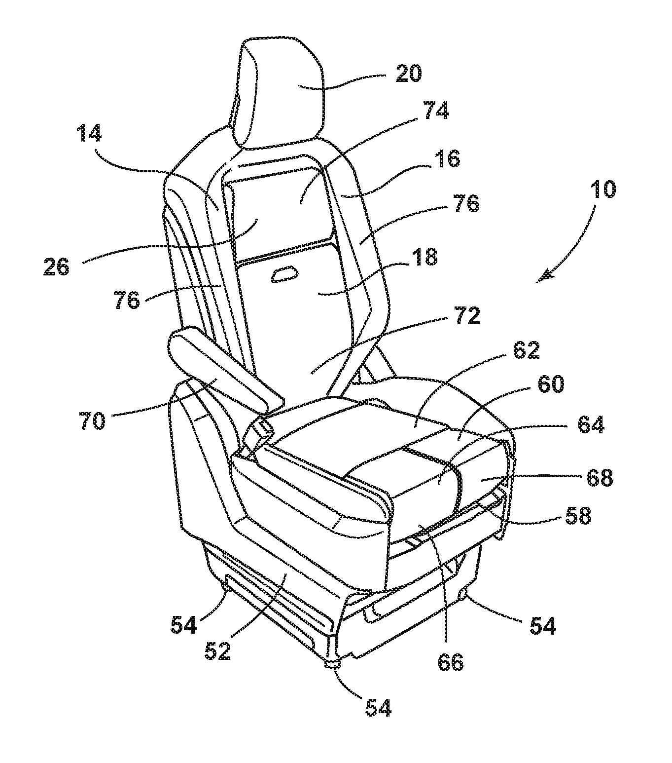
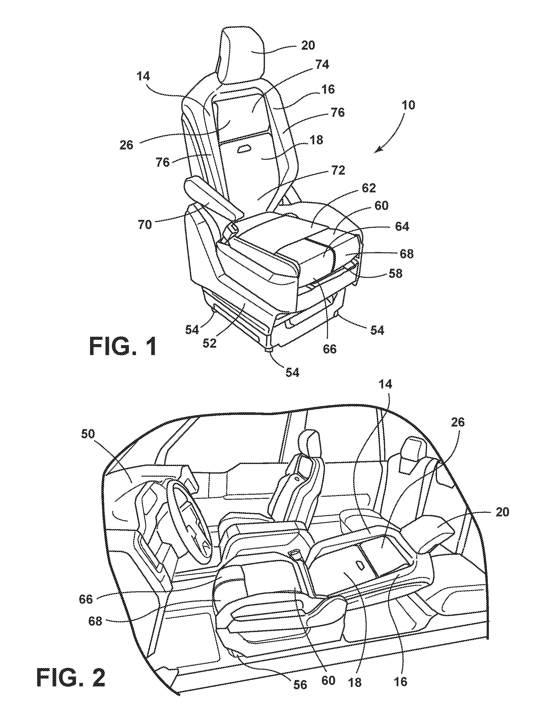
FIG. 1 is a top perspective view of one embodiment of a seating assembly of the present disclosure;
FIG. 2 is a front perspective view of a seating assembly of the present disclosure disposed in a vehicle;
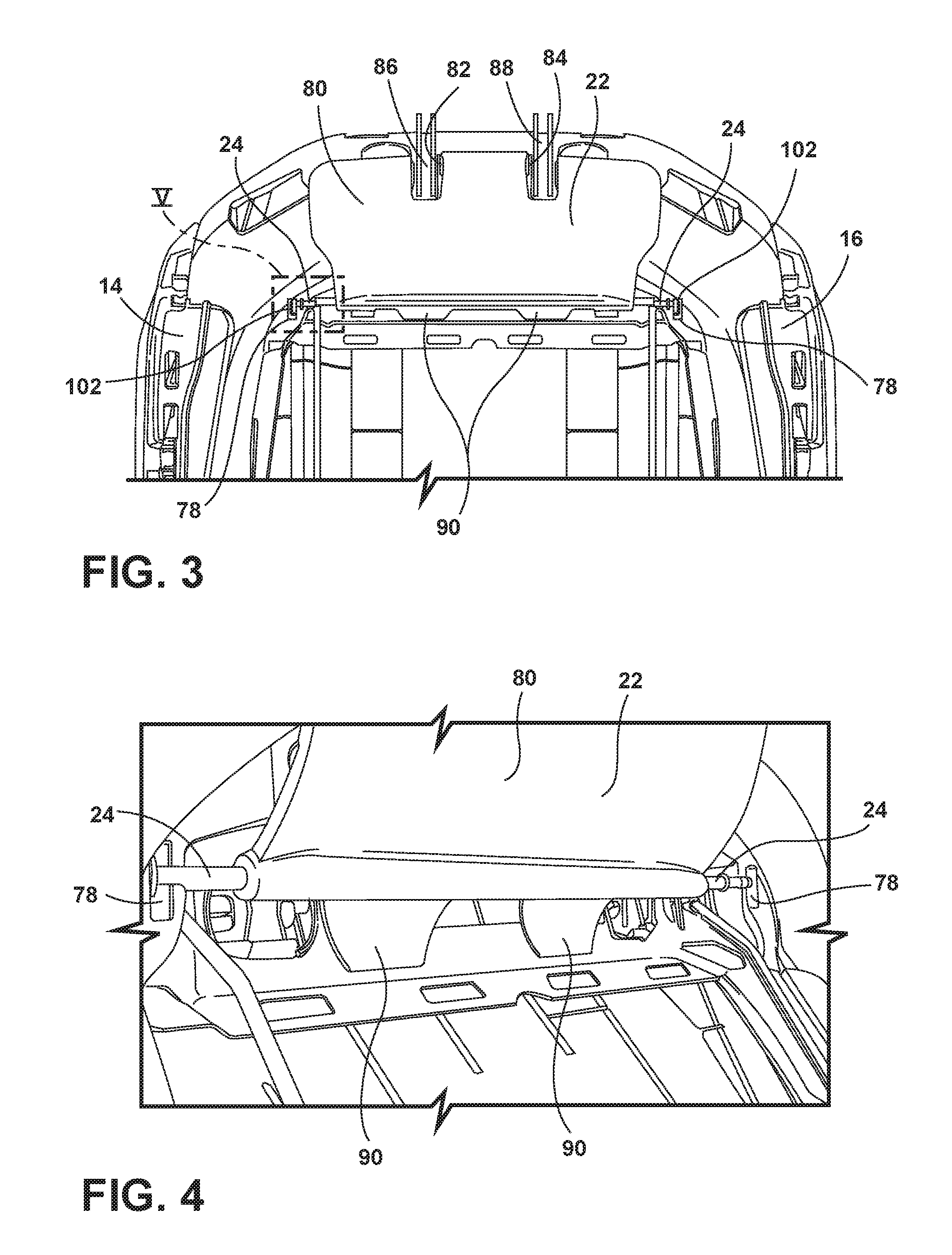
FIG. 3 is a partial front elevational view of a seating assembly of the present disclosure;
FIG. 4 is a partial perspective view of a lower pivot rod for use with a seating assembly of the present disclosure;
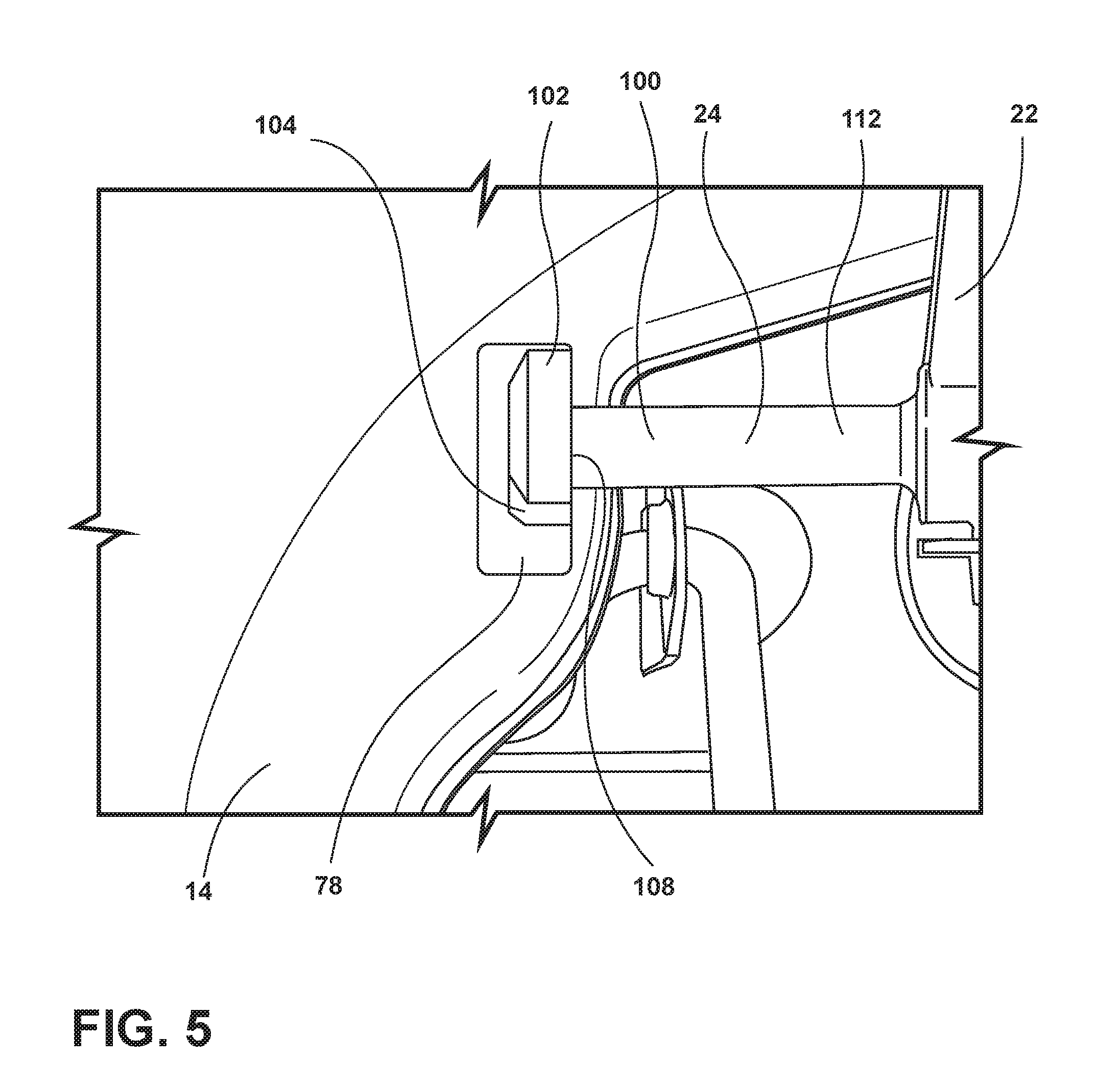
FIG. 5 is a partial front elevational view of a rod cap that is rotatably coupled with a seat frame of a seating assembly of the present disclosure;
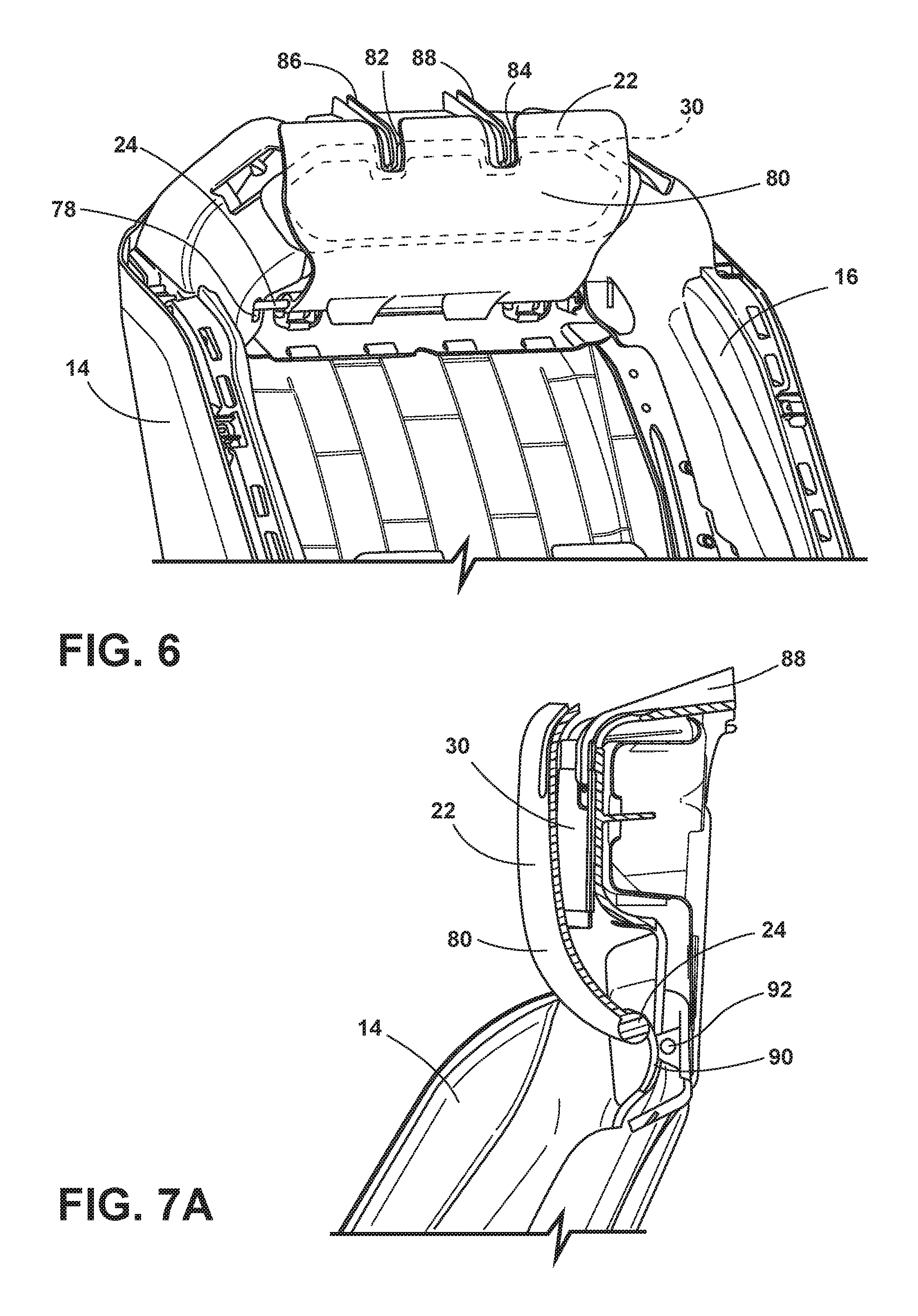
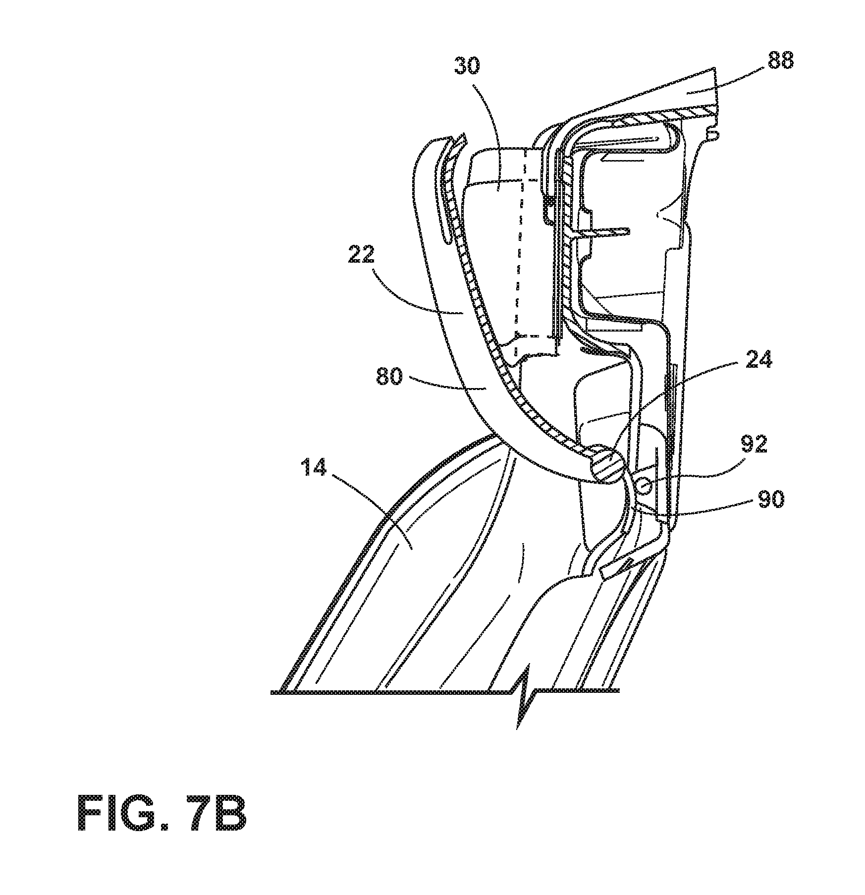
FIG. 6 is a front perspective view of a paddle for use with a seating assembly of the present disclosure;
FIG. 7A is a side cross-sectional view of a paddle operably coupled with a seating assembly of the present disclosure and in a retracted position;
FIG. 7B is a side elevational cross-sectional view of the seating assembly of FIG. 7A with the paddle in an extended position;
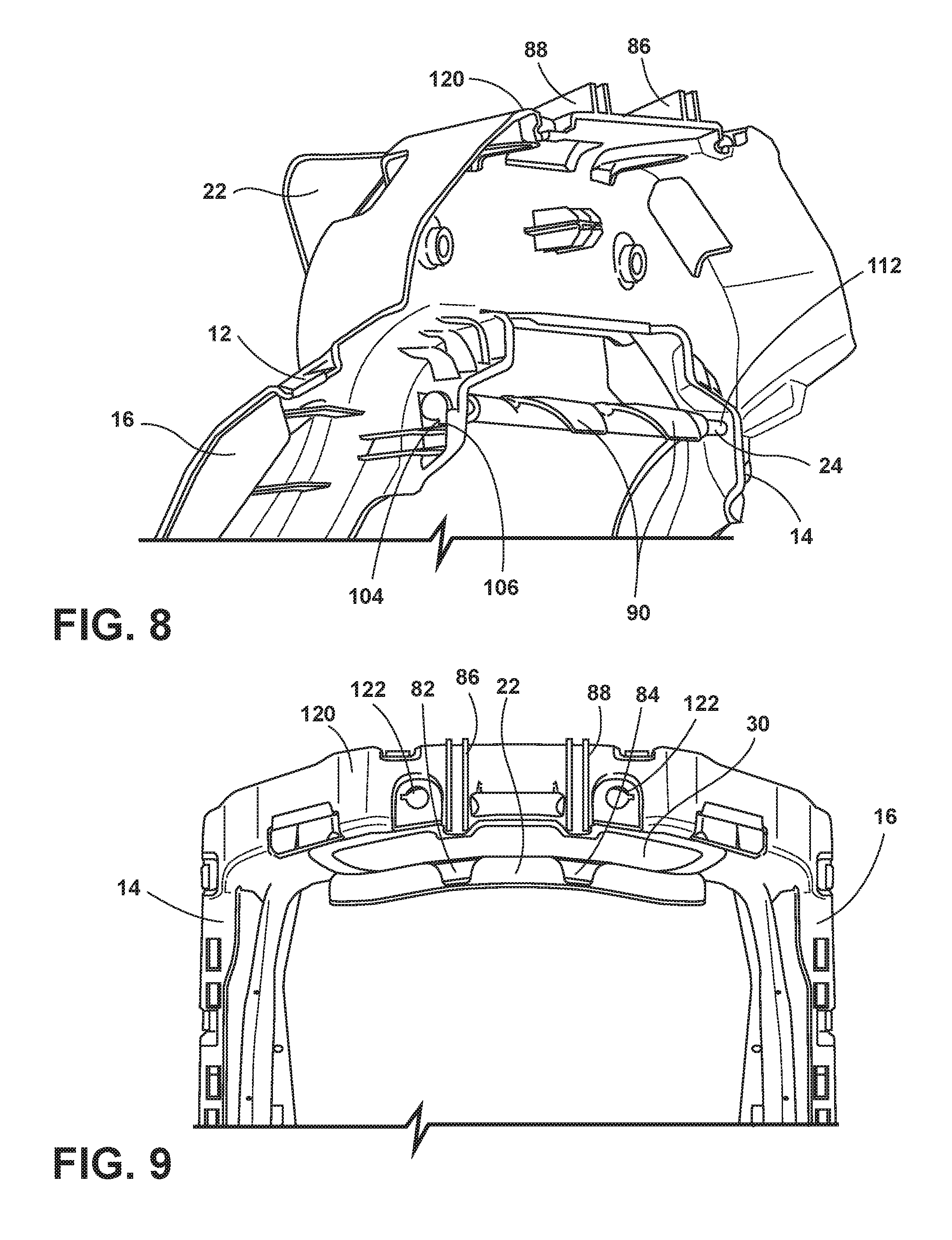
FIG. 8 is a rear perspective view of a seat frame of a seating assembly of the present disclosure;
FIG. 9 is a top plan view of a seating assembly of the present disclosure;
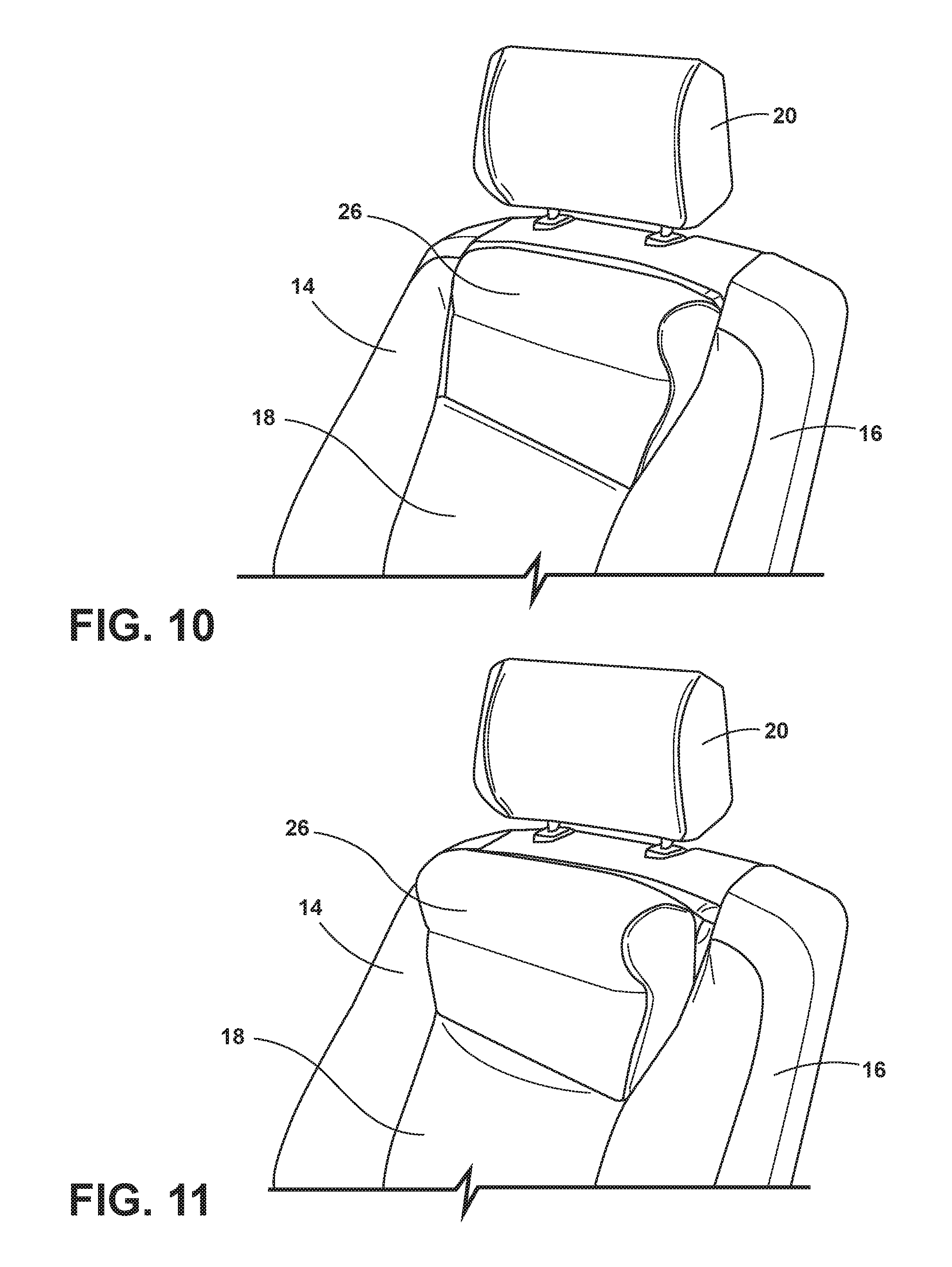
FIG. 10 is a side perspective view of an upper thoracic cushion support for a seating assembly of the present disclosure in a retracted position;
FIG. 11 is a side perspective view of an upper thoracic cushion support for a seating assembly of the present disclosure in an extended position; and
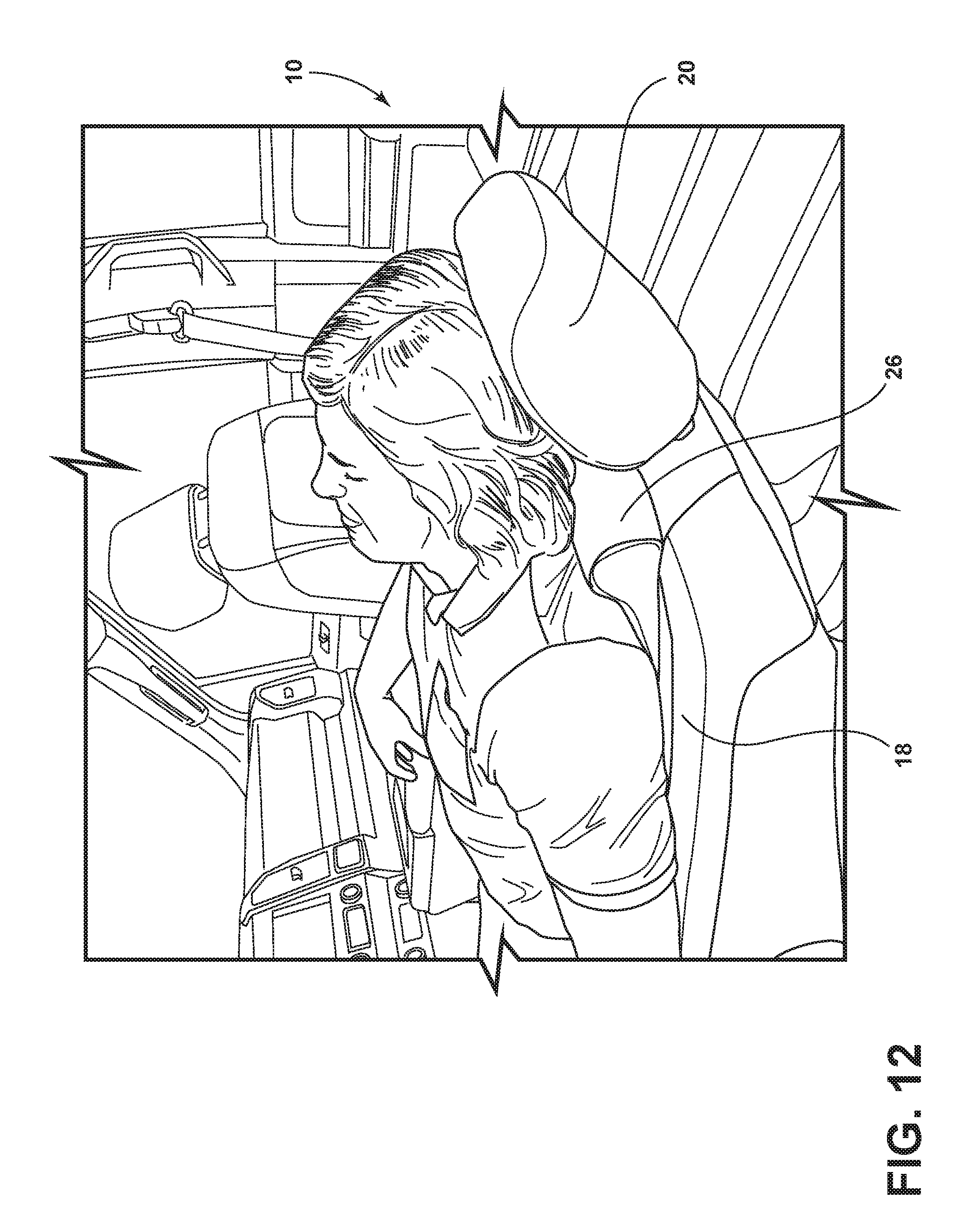
FIG. 12 is a rear perspective view of an occupant utilizing the upper thoracic support of a seating assembly of the present disclosure.
DETAILED DESCRIPTION OF THE EMBODIMENTS
For purposes of description herein, the terms "upper," "lower," "right," "left," "rear," "front," "vertical," "horizontal," and derivatives thereof shall relate to the disclosure as oriented in FIG. 1. However, it is to be understood that the disclosure may assume various alternative orientations, except where expressly specified to the contrary. It is also to be understood that the specific devices and processes illustrated in the attached drawings, and described in the following specification are simply exemplary embodiments of the inventive concepts defined in the appended claims. Hence, specific dimensions and other physical characteristics relating to the embodiments disclosed herein are not to be considered as limiting, unless the claims expressly state otherwise.
In this document, relational terms, such as first and second, top and bottom, and the like, are used solely to distinguish one entity or action from another entity or action, without necessarily requiring or implying any actual such relationship or order between such entities or actions. The terms "comprises," "comprising," or any other variation thereof, are intended to cover a non-exclusive inclusion, such that a process, method, article, or apparatus that comprises a list of elements does not include only those elements but may include other elements not expressly listed or inherent to such process, method, article, or apparatus. An element proceeded by "comprises . . . a" does not, without more constraints, preclude the existence of additional identical elements in the process, method, article, or apparatus that comprises the element.
Referring to the embodiment generally illustrated in FIGS. 1-12, reference numeral 10 generally designates a seating assembly that includes a frame 12 (FIG. 2) having first and second side members 14, 16. A seatback 18 and a head restraint 20 are supported on the frame 12. A paddle 22 includes a lower pivot rod 24 pivotally coupled between the first and second side members 14, 16 of the frame 12. The paddle 22 is disposed proximate a top portion 26 of the seatback 18, below the head restraint 20. A bladder 30 is disposed between the paddle 22 and the frame 12 and is operable between an inflated condition (FIG. 7B), wherein the paddle 22 is pivoted forward to support at least one of the upper back and neck of an occupant, and a deflated condition (FIG. 7A), wherein the paddle 22 is pivoted rearward into the seatback 18.
With reference to FIG. 1, the seating assembly 10 is generally constructed for use in a variety of environments, including residential or commercial applications, as well as in vehicles 50. The seating assembly 10 generally includes a seat base 52 supported on feet 54. The feet 54 may be operably coupled with a floor 56 of the vehicle 50. It will be understood that the feet 54 may be slidably coupled with the floor 56 or may maintain a stationary position relative to the floor 56 of the vehicle 50. The seat base 52 extends upwardly from the feet 54 and is configured to support a suspension assembly 58 and a seat 60. The seat 60 includes a cushion assembly configured to provide comfort to an occupant. In addition, the seat 60 includes a rear portion 62 and a forward portion 64. The forward portion 64 may include independent thigh supports 66, 68 configured to independently support each leg of an occupant. The seatback 18 is operably coupled with the seat 60 and is configured to pivot relative to the seat 60. In addition, the seatback 18 may include one or more seatback arms 70 pivotally coupled with the seatback 18. The seatback arms 70 provide support to the arms of an occupant. The seatback 18 includes a lower lumbar cushion 72 and an upper thoracic cushion 74. The upper thoracic cushion 74 is disposed proximate the paddle 22 and configured to rotate relative to the seatback 18. The seatback 18 also includes side bolsters 76 configured to cradle the sides of an occupant. The head restraint 20 is disposed on the seatback 18 and is operable between a plurality of vertical positions relative to the seatback 18.
Referring again to FIGS. 1 and 2, the seating assembly 10 is generally configured to provide sleeping accommodations to an occupant. Accordingly, the seatback 18 is configured to pivot rearward relative to the seat 60, such that the seat 60 and the seatback 18 are aligned or nearly aligned (FIG. 2). In this configuration, the seating assembly 10 can provide comfort to an occupant that wishes to rest or sleep for a period of time without leaving the safety of the vehicle 50. In an effort to provide increased comfort and support to the upper back of an occupant, the paddle 22 can rotate upward into abutting contact with an upper portion of the back of an occupant. This additional support lessens strain on the head and neck of the occupant.
With reference now to FIGS. 3 and 4, the paddle 22 is illustrated in further detail. The paddle 22 includes an arcuate body 80 that extends across an upper portion of the seatback 18. The paddle 22 is rotatable about an axis defined by the lower pivot rod 24. The lower pivot rod 24 is configured to extend through apertures 78 defined in each of the first and second side members 14, 16, of the frame 12. The lower pivot rod 24 may be operably coupled with, or may be integrally formed as part of, the paddle 22. The arcuate body 80 generally follows the contours of the upper back of an occupant. In addition, the paddle 22 includes first and second upper slots 82, 84 configured to align with first and second alignment features 86, 88, in the form of upper support flanges, disposed on a top portion of the frame 12 of the seating assembly 10. As the paddle 22 moves to a retracted position, the first and second upper slots 82, 84 receive the first and second alignment features 86, 88 of the frame 12.
With reference again to FIG. 4, the paddle 22 includes lower spring tabs 90 that rotate the paddle 22 to the retracted position when the bladder 30 is in the deflated condition. The lower spring tabs 90 act against a cross-member 92 that extends laterally between the first and second side members 14, 16. The spring tabs 90 may be formed as part of the paddle 22 or may be features operably coupled with the paddle 22. The paddle 22 may include a single spring tab 90 or several spring tabs 90. Regardless, the spring tabs 90 deflect against the cross-member 92 as the bladder 30 inflates and rotates the paddle 22 forward. As the bladder 30 deflates, the spring tabs 90 force rotation of the paddle 22 back to the retracted position.
With reference now to FIG. 5, distal ends 100 of the lower pivot rod 24 include a hub in the form of rod caps 102 that have a generally circular configuration. Each rod cap 102 includes a tab 104 that prevents overtravel of the paddle 22 when the paddle 22 moves to an extended position. The rod caps 102 may be snap-fittingly engaged with the first and second side members 14, 16. Stops 106 (FIG. 8) on a back portion of the first and second side members 14, 16 are configured to abut the tabs 104 on the rod caps 102 of the lower pivot rod 24. Overtravel tabs may also be positioned on the rod caps 102 to prevent the paddle 22 from moving too far rearward when the bladder 30 moves to the deflated condition and the paddle 22 moves to the retracted position. In the illustrated embodiment of FIG. 5, an outer portion 108 of the lower pivot rod 24 extends through and rotates within the receiving aperture 78 in each of the first and second side members 14, 16. An inner portion 112 of the lower pivot rod 24 proximate the paddle 22 may be exposed or may be coated with a plastic or other polymeric material. It will be understood that the paddle 22 may be constructed from a variety of materials, including plastic, metal, etc. Regardless of the material choice, the paddle 22 will have at least some limited ability to deflect under the weight of an occupant, yet provide sufficient support to the upper back of an occupant.
With reference now to FIG. 6, the distal ends 100 of the lower pivot rod 24 extend into the receiving aperture 78, but are hidden behind a front side of the first and second side members 14, 16. The bladder 30 is disposed behind the paddle 22. The bladder 30 may be operably coupled with a rear portion of the frame 12 via fasteners, adhesive, hook-and-loop attachments, etc. A forward portion of the bladder 30 is slidably coupled with a rear portion of the paddle 22. Accordingly, as the bladder 30 inflates, the paddle 22 rotates forward sliding against the paddle 22. It will be understood that the bladder 30 may also be operably coupled with a back side of the paddle 22 and slidably coupled with the top portion of the frame 12. In this instance, as the bladder 30 inflates, the bladder 30 would slide along the top portion of the frame 12. Regardless, the bladder 30 is operable between the inflated and deflated conditions to move the paddle 22 between the extended position and the retracted position, respectively. Further, it will be understood that the paddle 22 is hidden below the upper thoracic cushion 74 of the seatback 18. Accordingly, the paddle 22 is not exposed to the occupant.
With reference now to FIGS. 7A and 7B, movement of the paddle 22 from the retracted position to the extended position is illustrated. Movement of the paddle 22 from the retracted position to the extended position is made possible by the bladder 30, which is operable between the deflated condition (FIG. 7A) and the inflated condition (FIG. 7B). As previously noted, the tabs 104 on the rod caps 102 are configured to engage the stops 106 on the first and second side members 14, 16 of the frame 12 to prevent overtravel of the paddle 22.
With reference now to FIGS. 8 and 9, the seating assembly 10 is illustrated in more detail with portions of the seating assembly 10 removed to show the inner workings of the paddle 22 and movement of the 22 relative to the seatback 18. Notably, the paddle 22 is disposed in the top portion of the seatback 18 behind the upper thoracic cushion 74. An upper cross-member 120 of the frame 12 includes post receiving apertures 122 configured to receive posts of the head restraint 20. It is generally contemplated that the paddle 22 and the upper thoracic cushion 74 are designed to act in concert with the head restraint 20 to provide a uniform support interface to the upper back, neck, and head of an occupant. As noted herein, it will also be understood that the degrees of support between the upper thoracic cushion 74 and the head restraint 20 may vary, depending on occupant preferences, as well as the size and shape of the head, neck, and upper back of varying occupants.
With reference now to FIGS. 10-12, movement of the upper thoracic cushion 74 is illustrated. The upper thoracic cushion 74 is operable between the retracted position (FIG. 10) and the extended position (FIG. 11) as a result of the paddle 22 behind the upper thoracic cushion 74 rotating forward and rearward about the lower pivot rod 24. It will be understood that the paddle 22 may be adjusted via a manual operation of an actuator that activates a fluid pump (e.g., an air pump) in fluid communication with the bladder 30 and which inflates or deflates the bladder 30. It will also be understood that the bladder 30 may be part of an autonomous comfort system that inflates and deflates based on user preferences, or based on the relative rotation of the seatback 18 relative to the seat 60. For example, the seatback 18 may rotate relative to the seat 60 to align the seatback 18 with the seat (so an occupant can rest or sleep), and in so doing, the bladder 30 may inflate incrementally as the seatback 18 lowers. In addition, the bladder 30 may be conditioned to deflate as the seatback 18 returns to a more vertical position (typically used for commuting). The volume of fluid (most likely air) provided to the bladder 30 may be dictated by a control circuit operably coupled with the fluid pump. The control circuit may also be operable to receive instructions to allow for manual inflation and deflation of the bladder 30, resulting in a desired condition of the upper thoracic cushion 74 between extended and retracted positions.
It will be understood by one having ordinary skill in the art that construction of the described disclosure and other components is not limited to any specific material. Other exemplary embodiments of the disclosure disclosed herein may be formed from a wide variety of materials, unless described otherwise herein.
For purposes of this disclosure, the term "coupled" (in all of its forms, couple, coupling, coupled, etc.) generally means the joining of two components (electrical or mechanical) directly or indirectly to one another. Such joining may be stationary in nature or moveable in nature. Such joining may be achieved with the two components (electrical or mechanical) and any additional intermediate members being integrally formed as a single unitary body with one another or with the two components. Such joining may be permanent in nature or may be removable or releasable in nature unless otherwise stated.
It is also important to note that the construction and arrangement of the elements of the disclosure as shown in the exemplary embodiments is illustrative only. Although only a few embodiments of the present innovations have been described in detail in this disclosure, those skilled in the art who review this disclosure will readily appreciate that many modifications are possible (e.g., variations in sizes, dimensions, structures, shapes and proportions of the various elements, values of parameters, mounting arrangements, use of materials, colors, orientations, etc.) without materially departing from the novel teachings and advantages of the subject matter recited. For example, elements shown as integrally formed may be constructed of multiple parts or elements shown as multiple parts may be integrally formed, the operation of the interfaces may be reversed or otherwise varied, the length or width of the structures and/or members or connector or other elements of the system may be varied, the nature or number of adjustment positions provided between the elements may be varied. It should be noted that the elements and/or assemblies of the system may be constructed from any of a wide variety of materials that provide sufficient strength or durability, in any of a wide variety of colors, textures, and combinations. Accordingly, all such modifications are intended to be included within the scope of the present innovations. Other substitutions, modifications, changes, and omissions may be made in the design, operating conditions, and arrangement of the desired and other exemplary embodiments without departing from the spirit of the present innovations.
It will be understood that any described processes or steps within described processes may be combined with other disclosed processes or steps to form structures within the scope of the present disclosure. The exemplary structures and processes disclosed herein are for illustrative purposes and are not to be construed as limiting.
It is also to be understood that variations and modifications can be made on the aforementioned structures and methods without departing from the concepts of the present disclosure, and further it is to be understood that such concepts are intended to be covered by the following claims unless these claims by their language expressly state otherwise.
* * * * *
D00000
D00001
D00002
D00003
D00004
D00005
D00006
D00007
D00008
XML
uspto.report is an independent third-party trademark research tool that is not affiliated, endorsed, or sponsored by the United States Patent and Trademark Office (USPTO) or any other governmental organization. The information provided by uspto.report is based on publicly available data at the time of writing and is intended for informational purposes only.
While we strive to provide accurate and up-to-date information, we do not guarantee the accuracy, completeness, reliability, or suitability of the information displayed on this site. The use of this site is at your own risk. Any reliance you place on such information is therefore strictly at your own risk.
All official trademark data, including owner information, should be verified by visiting the official USPTO website at www.uspto.gov. This site is not intended to replace professional legal advice and should not be used as a substitute for consulting with a legal professional who is knowledgeable about trademark law.