Log wall construction
Ross April 20, 2
U.S. patent number 10,982,436 [Application Number 16/734,068] was granted by the patent office on 2021-04-20 for log wall construction. The grantee listed for this patent is John P. Ross. Invention is credited to John P. Ross.
| United States Patent | 10,982,436 |
| Ross | April 20, 2021 |
Log wall construction
Abstract
A log wall construction including a plurality of log blocks, each having a substantially same height-dimension and laid next to each other to form a log block row having a log block row length. Log blocks next to each other have at least one pair of adjacent curved surfaces for each pair of log blocks next to each other. A second log block row of the plurality of log blocks laid next to each other to form the second log block row having a second log block row length and being located on top of the first log block row. A stringer located between the log block row and the second log block row and separating each log block row from each other log block row. The stringer extends substantially an entire distance equivalent to both the log block row length and the second log block row length.
| Inventors: | Ross; John P. (Neenah, WI) | ||||||||||
|---|---|---|---|---|---|---|---|---|---|---|---|
| Applicant: |
|
||||||||||
| Family ID: | 1000004576598 | ||||||||||
| Appl. No.: | 16/734,068 | ||||||||||
| Filed: | January 3, 2020 |
| Current U.S. Class: | 1/1 |
| Current CPC Class: | E04B 2/702 (20130101) |
| Current International Class: | E04B 2/70 (20060101) |
| Field of Search: | ;52/233 |
References Cited [Referenced By]
U.S. Patent Documents
| 1566228 | December 1925 | Ryan |
| 1601106 | September 1926 | Carver |
| 1887777 | November 1932 | Morris |
| 1941436 | December 1933 | Haupt |
| 2073673 | March 1937 | Blake |
| 2074813 | March 1937 | Sill |
| 2112861 | April 1938 | O'Hagen |
| 2142404 | January 1939 | Mueller |
| 2183620 | December 1939 | Myers |
| 2192366 | March 1940 | Poroma |
| 2320466 | June 1943 | Presley |
| 2550883 | May 1951 | St Vincent |
| 2826906 | March 1958 | Rice |
| 3343328 | September 1967 | Rolle |
| 3618279 | November 1971 | Sease |
| 3863409 | February 1975 | Fell |
| 4021983 | May 1977 | Kirk, Jr. |
| 4047350 | September 1977 | Chisum |
| 4823528 | April 1989 | Faw |
| 4946632 | August 1990 | Pollina |
| 4996813 | March 1991 | Kliethermes, Jr. |
| 5003746 | April 1991 | Wilston |
| 5119587 | June 1992 | Waltz |
| 5154032 | October 1992 | Ritter |
| 5181362 | January 1993 | Benitez |
| 5265390 | November 1993 | Tanner |
| 5337527 | August 1994 | Wagenaar |
| 5421135 | June 1995 | Stevens |
| 5537796 | July 1996 | Kliethermes, Jr. |
| 5577357 | November 1996 | Civelli |
| 5651642 | July 1997 | Kelley, Jr. |
| 6023895 | February 2000 | Anderson |
| 6053661 | April 2000 | Lewis |
| 6363672 | April 2002 | Baker |
| 6385929 | May 2002 | Englehart |
| 6455113 | September 2002 | Bilodeau |
| 6907705 | June 2005 | Dean |
| 7387472 | June 2008 | Abella |
| 7413081 | August 2008 | Rogers |
| 8701364 | April 2014 | Wrightman |
| 2002/0026763 | March 2002 | Schmitz |
| 2003/0029123 | February 2003 | Pignataro |
| 2003/0233799 | December 2003 | Chavez |
| 2004/0182029 | September 2004 | Berg |
| 2004/0187411 | September 2004 | Clegg |
| 2005/0091940 | May 2005 | Whitson |
| 2006/0059824 | March 2006 | Barbisch |
| 2006/0242914 | November 2006 | Stephansky |
| 2006/0248816 | November 2006 | Williams |
| 2007/0056235 | March 2007 | Kohler |
| 2007/0130852 | June 2007 | Sieber |
| 2007/0130860 | June 2007 | Paquette |
| 2007/0137128 | June 2007 | Viau |
| 2007/0163203 | July 2007 | Price |
| 2007/0251182 | November 2007 | Van Steinburg |
| 2007/0261365 | November 2007 | Keene |
| 2008/0298902 | December 2008 | Knudson |
| 2009/0133345 | May 2009 | Wrightman |
| 2010/0043323 | February 2010 | Wrightman |
| 2010/0218447 | September 2010 | Gehring |
| 2011/0146171 | June 2011 | Flatland |
| 2011/0203197 | August 2011 | Najafi |
| 2011/0289877 | December 2011 | Correia |
| 2012/0096793 | April 2012 | Riccobene |
| 2012/0174511 | July 2012 | Harding |
| 2013/0008107 | January 2013 | Herman |
| 2013/0305646 | November 2013 | Mann |
| 2014/0041331 | February 2014 | Buoni |
| 2015/0286752 | October 2015 | Karau |
| 2016/0222655 | August 2016 | Lin |
| 2016/0244936 | August 2016 | MacDonald |
| 2020/0011065 | January 2020 | Saniepey |
| 2020/0024850 | January 2020 | Fox |
| 2020/0048906 | February 2020 | Honkala |
| 101053198 | Aug 2011 | KR | |||
| 101602764 | Mar 2016 | KR | |||
| 2580670 | Apr 2016 | RU | |||
Other References
|
Rob Roy, Youtube video at this link: https://www.youtube.com/watch?v=IBekqHymLfo, dated at least as early as Sep. 19, 2019, with relevant screen shots attached as pp. 1-5, and viewed in the United States on the internet. cited by applicant . Goggle Images, file name "Log Home Joinery--Comfort System 5", dated at least as early as Sep. 19, 2019, 1 page, and viewed in the United States on the internet. cited by applicant . Goggle Images, file name "Cordwood Construction dot org", dated at least as early as Sep. 19, 2019, 1 page, and viewed in the United States on the internet. cited by applicant . Goggle Images, file name "Poleshed example", dated at least as early as Sep. 19, 2019, 1 page, and viewed in the United States on the internet. cited by applicant . Goggle Images, file name "Sojourn cabin", dated at least as early as Sep. 19, 2019, 3 pages, and viewed in the United States on the internet. cited by applicant . Google Images, file name "partial building corewood", dated at least as early as Sep. 19, 2019, 1 page, and viewed in the United States on the internet. cited by applicant . Google Images, file name "another example corewood build", dated at least as early as Sep. 19, 2019, 1 page, and viewed in the United States on the internet. cited by applicant . Google Images, file name "still another example corewood build", dated at least as early as Sep. 19, 2019, 1 page, and viewed in the United States on the internet. cited by applicant . Google Images, file name "motar and insulation fill", dated at least as early as Sep. 19, 2019, 1 page, and viewed in the United States on the internet. cited by applicant. |
Primary Examiner: Walraed-Sullivan; Kyle J.
Attorney, Agent or Firm: Epiphany Law, LLC
Claims
What is claimed is:
1. A log wall construction comprising: a dwelling formed with a plurality of log blocks, each of the plurality of log blocks having a substantially same height-dimension; the plurality of log blocks laid next to each other to form a log block row having a log block row length, each log block having a top flat surface, a bottom flat surface, a front flat surface, a back flat surface, a right curved vertically sloped convex surface and a left curved vertically sloped convex surface, and where log blocks next to each other have at least one pair of adjacent curved vertically sloped convex surfaces for each pair of log blocks next to each other; a second log block row of the plurality of log blocks each having a second substantially same height-dimension and laid next to each other to form the second log block row having a second log block row length and being located on top of the log block row; and, a stringer located between the log block row and the second log block row and separating the flat top surface of each log block in the log block row from the flat bottom surface of each log block in the second log block row wherever log blocks of the log block row are adjacent to log blocks of the second log block row, the stringer extending substantially an entire distance that is equivalent to both the log block row length and the second log block row length.
2. The log wall construction of claim 1, wherein at least some of the log blocks are a full-sized log block.
3. The log wall construction of claim 1, wherein at least some of the log blocks are a half-sized log block.
4. The log wall construction of claim 3, wherein the half-sized log block has a width-dimension that is at least two times as long as a height-dimension.
5. The log wall construction of claim 1, wherein at least two log blocks next to each other have at least a portion of each log block touching each other at adjacent curved vertically sloped convex surfaces.
6. The log wall construction of claim 5, wherein substantially all log blocks next to each other have at least a portion of each log block touching each other at adjacent curved vertically sloped convex surfaces.
7. The log wall construction of claim 1, wherein the stringer has a front runner with a front stringer edge that is adjacent to the front flat surface of the log blocks and the stringer has a back runner with a back stringer edge that is adjacent to the back flat surface of the log blocks.
8. The log wall construction of claim 7, wherein the front runner is separated from the back runner.
9. The log wall construction of claim 8, wherein the front runner is distinct from and completely separated from the back runner.
10. The log wall construction of claim 7, wherein the stringer has a width-dimension that is at least two times as long as a height-dimension.
11. The log wall construction of claim 10, wherein the height-dimension of the stringer is between about 0.5 inches and about 1.5 inches.
12. The log wall construction of claim 10, wherein the width-dimension of the stringer is between about 1 inch and about 3 inches.
13. The log wall construction of claim 1, wherein a mechanical fastener secures the log block row to the second log block row.
14. The log wall construction of claim 13, wherein the mechanical fastener extends in and between at least a portion of the log block row and at least a portion of the second log block row.
15. The log wall construction of claim 1, comprising at least three log block rows.
16. The log wall construction of claim 15, comprising a room formed of log block rows.
17. A log wall construction comprising: a dwelling formed with a plurality of log blocks, each of the plurality of log blocks having a substantially same height-dimension; the plurality of log blocks laid next to each other to form a log block row having a log block row length, each log block having a top flat surface, a bottom flat surface, a front flat surface, a back flat surface, a right curved vertically sloped convex surface and a left curved vertically sloped convex surface, and where log blocks next to each other have at least one pair of adjacent curved vertically sloped convex surfaces for each pair of log blocks next to each other; a second log block row of the plurality of log blocks each having a second substantially same height-dimension and laid next to each other to form the second log block row having a second log block row length and being located on top of the first log block row; a stringer located between the log block row and the second log block row and separating the flat top surface of each log block in the log block row from the flat bottom surface of each log block in the second log block row wherever log blocks of the log block row are adjacent to log blocks of the second log block row, the stringer extending substantially an entire distance that is equivalent to both the log block row length and the second log block row length, and the stringer has a front runner with a front stringer edge that is adjacent to the front surface of the log blocks and the stringer has a back runner with a back stringer edge that is adjacent to the back surface of the log blocks; and wherein at least two log blocks next to each other have at least a portion of each log block touching each other at adjacent curved vertically sloped convex surfaces and each log block row has a same sized log block in that log block row.
18. The log wall construction of claim 17, wherein the front runner is distinct from and completely separated from the back runner.
19. The log wall construction of claim 17, wherein a log wall has substantially only the same sized log blocks in each log block row of the log wall.
20. The log wall construction of claim 17, wherein substantially all log blocks next to each other have at least a portion of each log block touching each other at adjacent curved vertically sloped convex surfaces.
Description
TECHNICAL FIELD
This invention relates to the use of logs to make dwellings and other buildings, and more particularly, is directed to log blocks of uniform thickness which can be laid in courses to easily build a log wall and thereby a dwelling.
BACKGROUND
Log cabins have been known and used as dwellings for hundreds of years. The current methods of building a log cabin include construction of a cabin by hand from logs in their natural shape, and construction of a cabin from interchangeable prefabricated logs produced in a manufacturing environment. In either method, logs are stacked horizontally crosswise to form a multi-walled structure.
The construction of a house or dwelling in the form of a log cabin has notable advantages, particularly in the strength and rigidity of the structure and in the thermal insulation provided by the thick wood logs. However, because of the difficulty of providing full logs, properly fitted so as to seal against the weather and maintenance of the same, the construction of houses by the uses of sawed lumber advanced while the construction of log cabins terminated. However, there are certain advantages in the use of a log cabin for style and comfort, but also in the fact that in many wilderness areas where industry requires the attendance of a number of people, it is difficult to provide the kind of saw mill required to cut logs to the proper lumber size for conventional housing construction.
Another common facet of conventional log building techniques is that the length or width of the home is dependent on the length of the logs. Having long logs has at least two major disadvantages. First, the price for logs exponentially increases in relation to the length needed, drastically driving up the cost of larger houses. Second, portions of many of these long logs are wasted, because most exterior walls are constructed as solid walls, with the logs extending the entire length of the wall. First, the log is cut to the desired length, creating wasted material. Openings for any doors or windows are cut out from the solid wall and the material removed from the openings is discarded. The home owner is paying for log material not utilized in the final house.
Traditional log buildings include full round logs and squared logs several feet in length stacked horizontally. Another method uses short cord wood pieces stacked into a wall made stable by the use of mortar as a construction component. However, the use of full logs is also cumbersome due to their size and weight which requires a crane or lift to work and place the logs. Narrow sections of log walls where two logs meet do not provide significant insulating value and require maintenance of the chinking. Cord wood logs laid with mortar can be very time consuming to construct and over time, unstable. And, because of the significant surface variations, modern interior and exterior finishing materials like siding, drywall, and plywood cannot be used.
The common techniques for log home construction have many non-desirable aspects, concerns, and maintenance problems associated with the dwelling. Accordingly, there is a need for more easily handled building materials which can (i) be laid in courses to build a log wall and dwelling and/or (ii) used with no special equipment or machinery to do the construction. Also, better insulating value than a traditional log wall can provide, is desired. These concerns, those of maintenance problems and high expenses, are drawbacks to any currently available log building.
SUMMARY
The log wall construction of the present invention minimizes, or may eliminate, one or more of the above-discussed concerns and problems. As such, there is provided a log wall construction. The wall construction includes a plurality of log blocks each having a substantially same height-dimension and laid next to each other to form a log block row. Each row has a log block row length. Each log block has a top flat surface, a bottom flat surface, a front flat surface, a back flat surface, a right curved surface and a left curved surface. Log blocks next to each other have at least one pair of adjacent curved surfaces for each pair of log blocks next to each other. The construction also includes a second log block row of the plurality of log blocks each having a second substantially same height-dimension and laid next to each other to form the second log block row. This row has a second log block row length and is located on top of the first log block row. And, the construction further includes a stringer located between the log block row and the second log block row and separating the flat top surface of each log block in the log block row from the flat bottom surface of each log block in the second log block row wherever log blocks of the log block row are adjacent to log blocks of the second log block row. The stringer extends substantially an entire distance that is equivalent to both the log block row length and the second log block row length.
In another aspect of the invention, there is provided a log wall construction. The construction includes a plurality of log blocks each having a substantially same height-dimension and laid next to each other to form a log block row having a log block row length. Each log block has a top flat surface, a bottom flat surface, a front flat surface, a back flat surface, a right curved surface and a left curved surface. Log blocks next to each other have at least one pair of adjacent curved surfaces for each pair of log blocks next to each other. Also includes is a second log block row of the plurality of log blocks each having a second substantially same height-dimension and laid next to each other to form the second log block row having a second log block row length and being located on top of the first log block row. Further, is included a stringer located between the log block row and the second log block row and separating the flat top surface of each log block in the log block row from the flat bottom surface of each log block in the second log block row wherever log blocks of the log block row are adjacent to log blocks of the second log block row. The stringer extends substantially an entire distance that is equivalent to both the log block row length and the second log block row length. The stringer has a front runner with a front stringer edge that is adjacent to the front surface of the log blocks and the stringer has a back runner with a back stringer edge that is adjacent to the back surface of the log blocks. Yet further, at least two log blocks next to each other have at least a portion of each block touching each other at their respective adjacent curved surfaces and each log block row has the same sized log block in that log block row.
Other aspects of the invention are directed to the configuration and features of the log blocks themselves and relative to each other, the configuration and features of the stringer, and the configuration and features of the log block rows.
BRIEF DESCRIPTION OF THE DRAWINGS
The invention may be more completely understood in consideration of the following detailed description of various embodiments of the invention in connection with the accompanying drawings, in which:
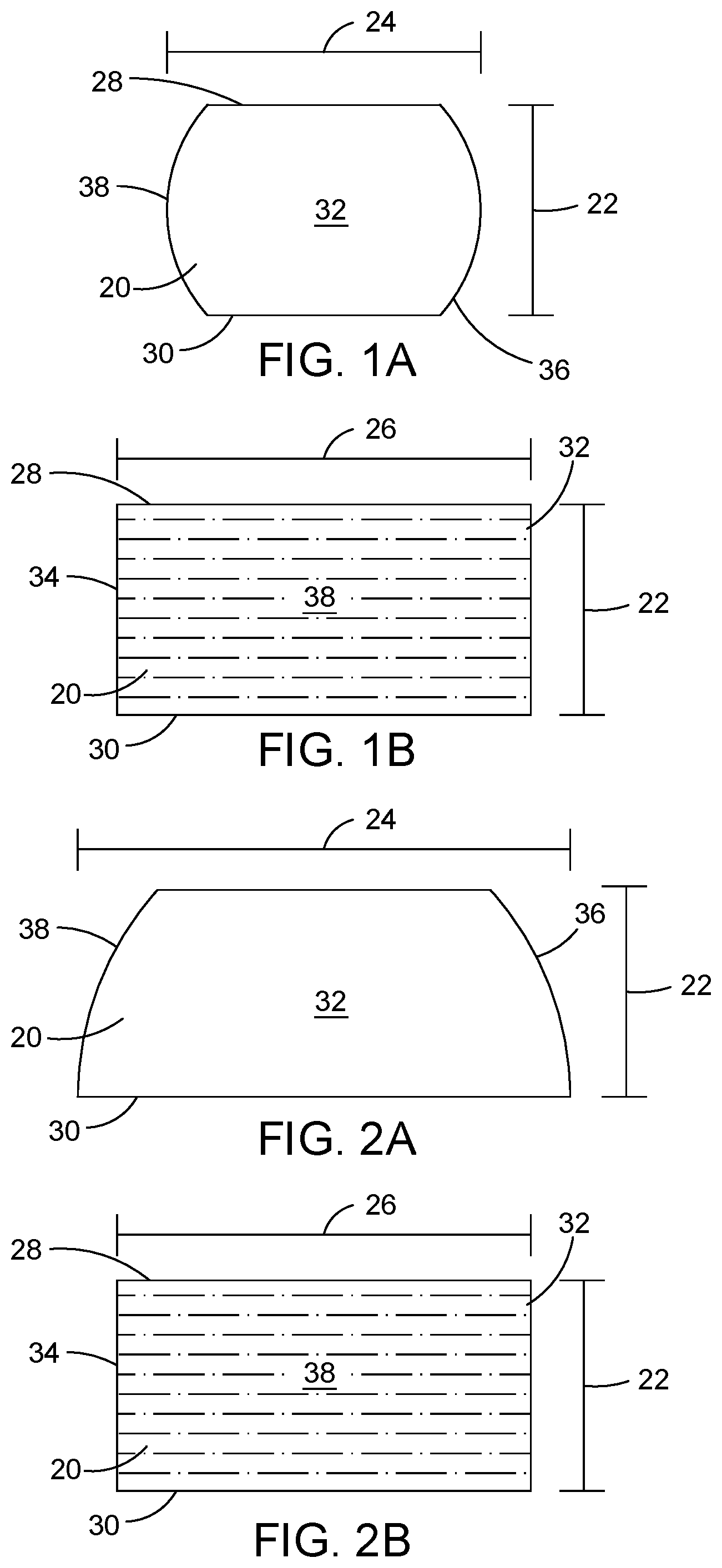
FIG. 1A is a front view of a log block of the invention;
FIG. 1B is a side view of that in FIG. 1A;
FIG. 2A is a front view of an alternate embodiment of a log block of the invention;
FIG. 2B is a side view of that in FIG. 2A;
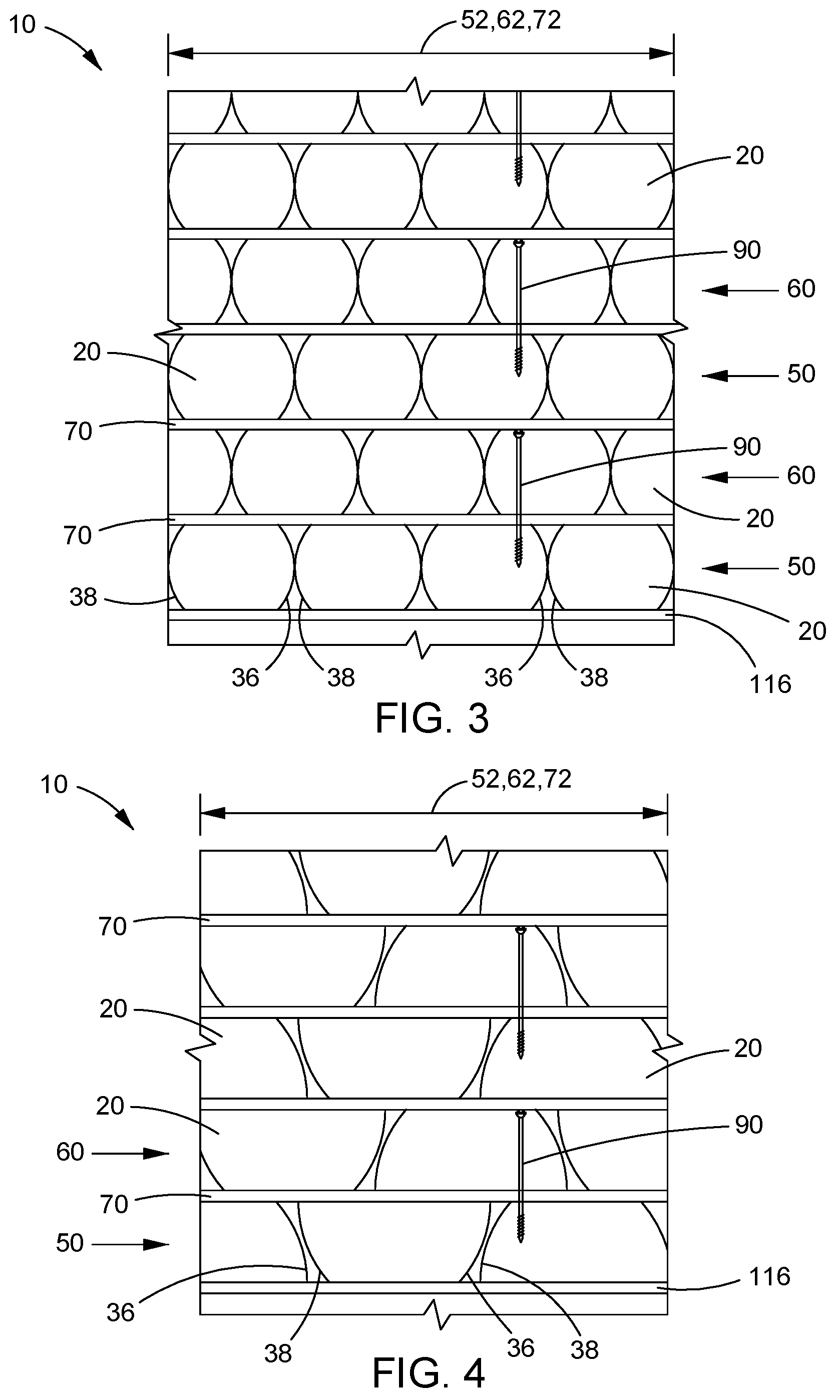
FIG. 3 is a front view of a log wall construction using the log block of FIG. 1A;
FIG. 4 is a front view of an alternate log wall construction using the log block of FIG. 2A;
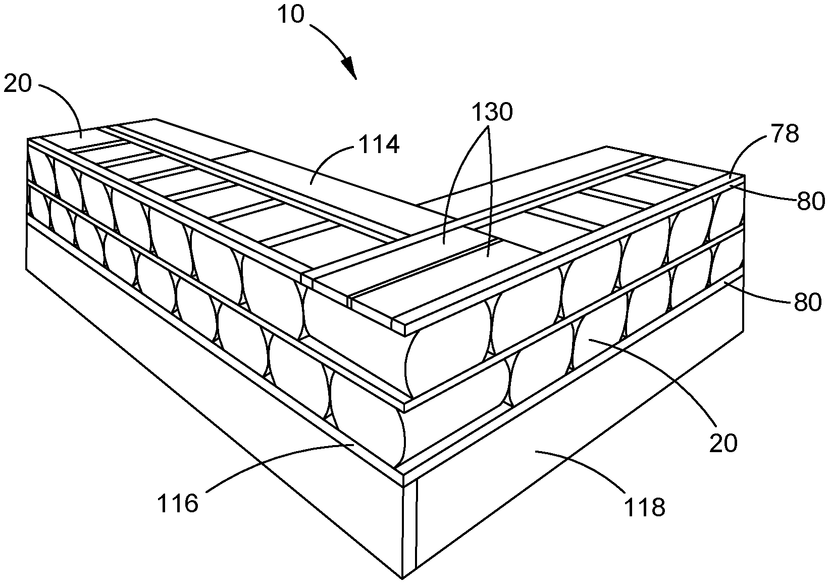
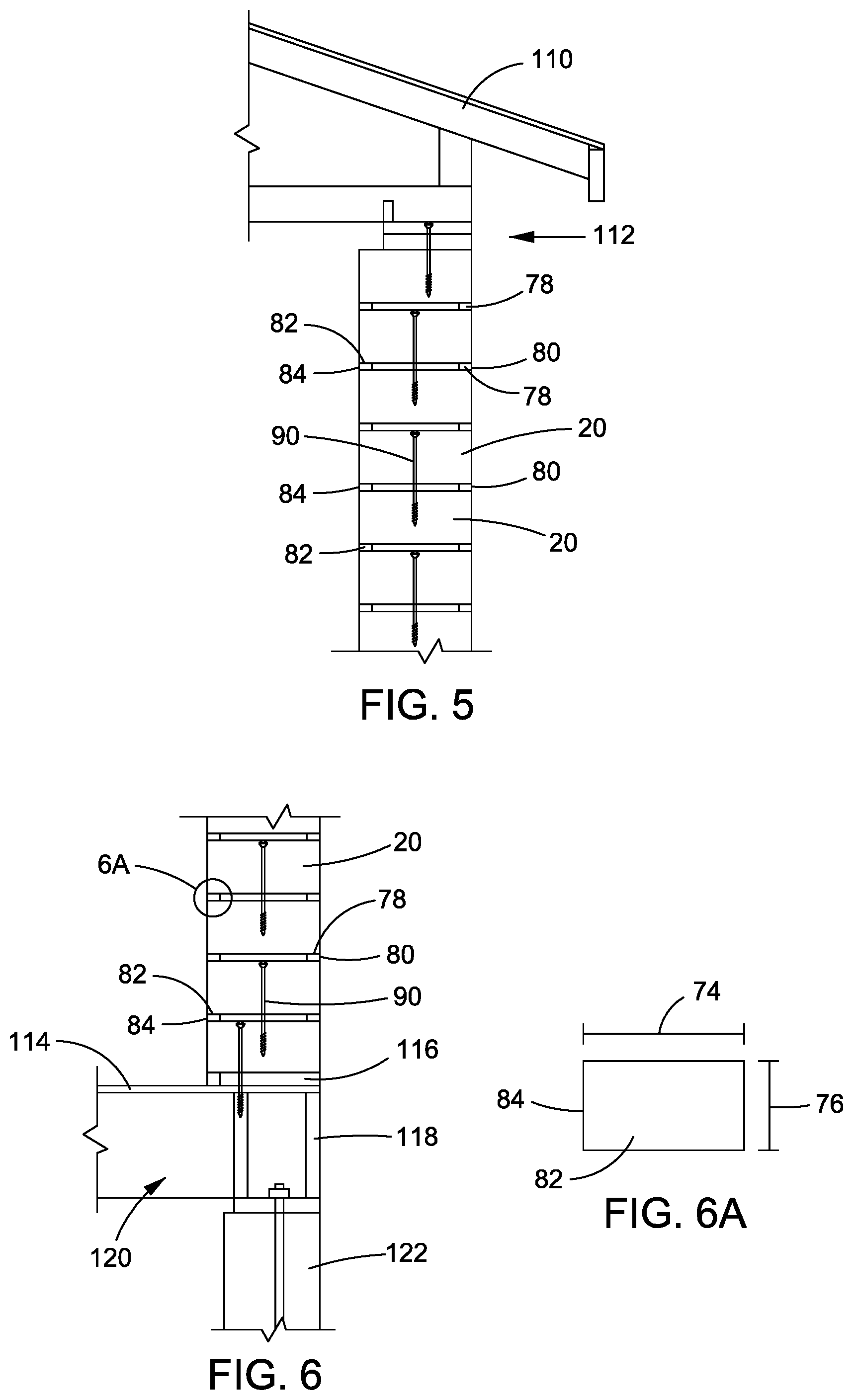
FIG. 5 is a cut-away end view of a log wall construction as a portion of a dwelling;
FIG. 6 is a cut-away end view of a log wall construction as a different portion of a dwelling;
FIG. 6A is an enlarged, focused view of the stringer seen in portion 6A of FIG. 6;
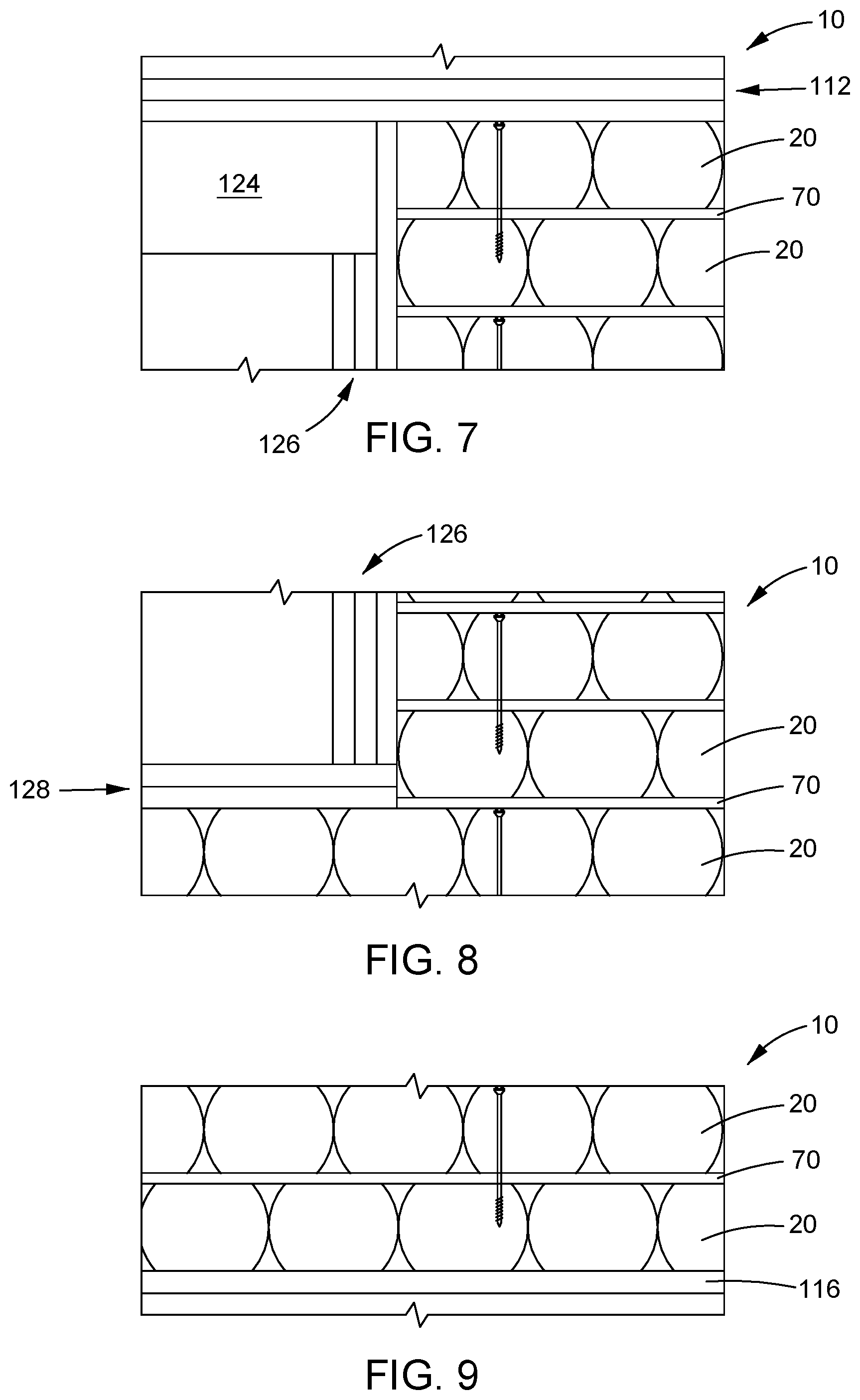
FIG. 7 is a front view of a log wall construction as a door portion of a dwelling;
FIG. 8 is a front view of a log wall construction as a window portion of a dwelling;
FIG. 9 is a front view of a log wall construction as a floor portion of a dwelling;
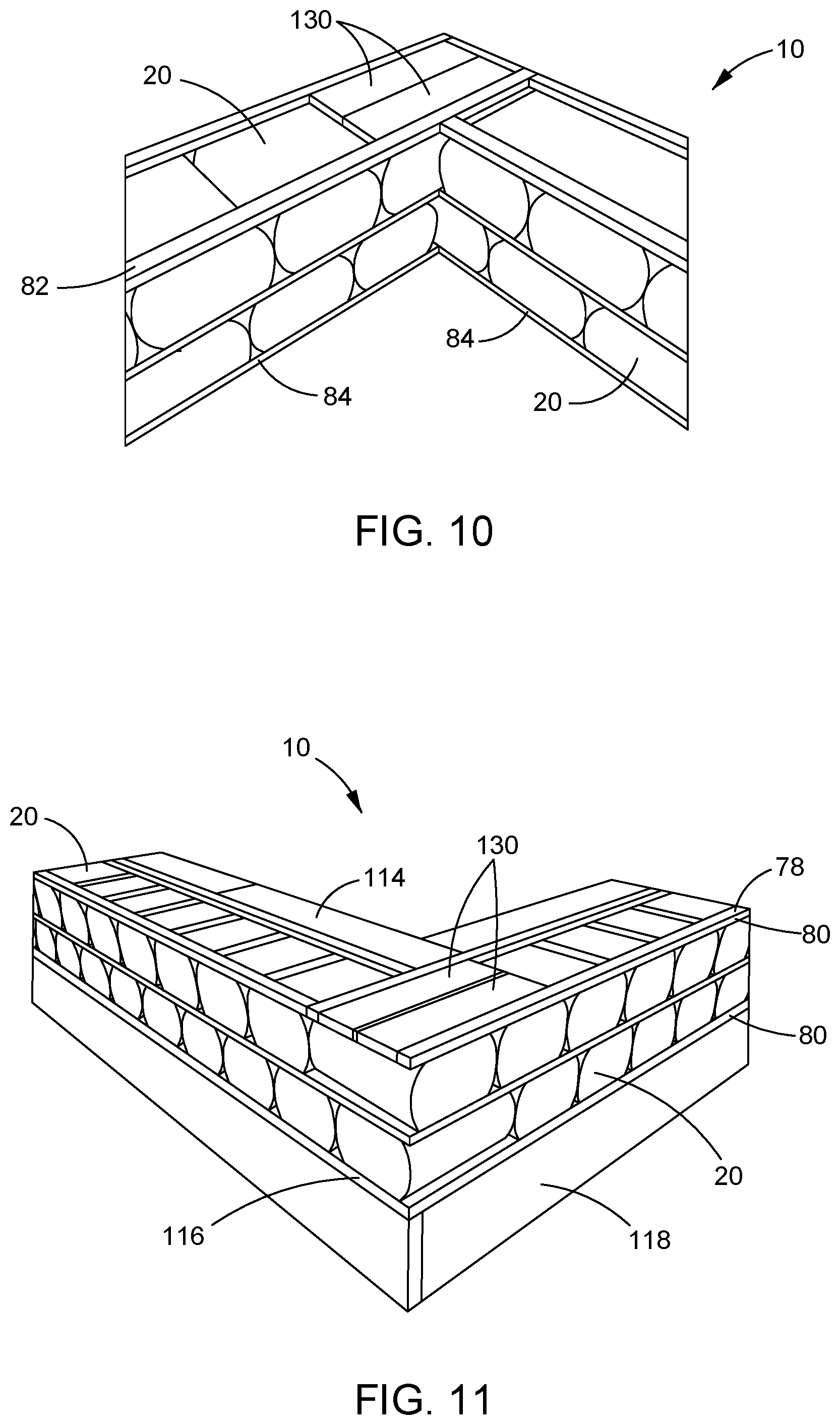
FIG. 10 is an isometric view of an interior portion of a log wall construction corner as a portion of a dwelling;
FIG. 11 is an isometric view of an exterior portion of a log wall construction corner as a portion of a dwelling;
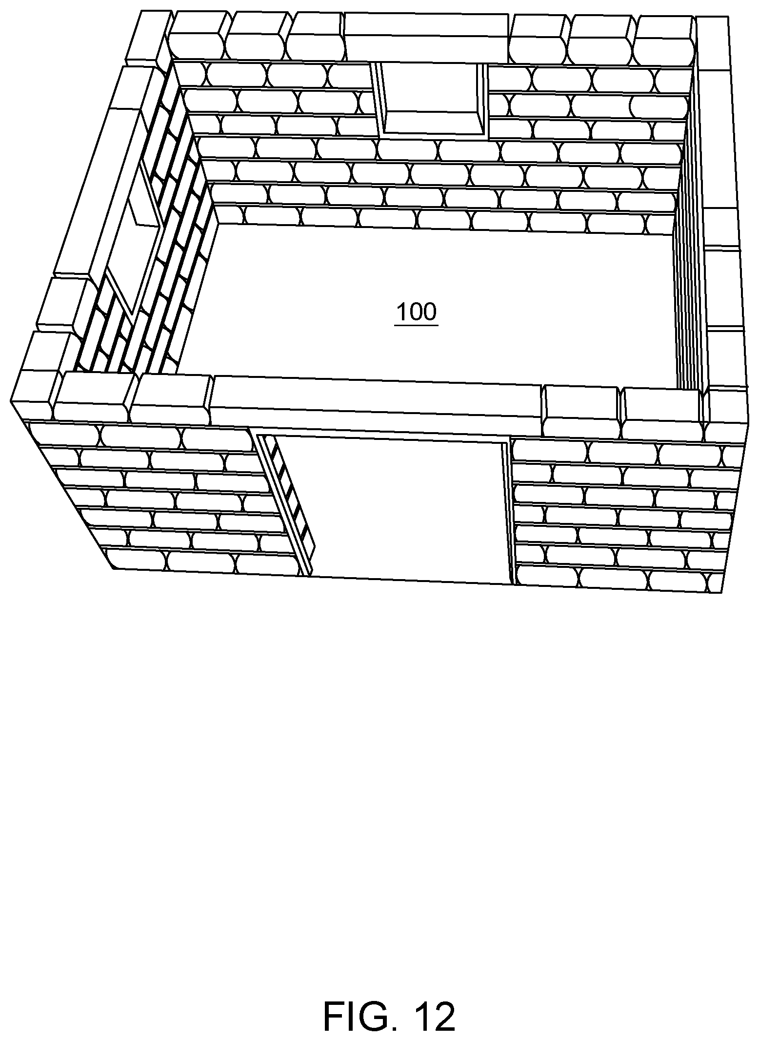
FIG. 12 is a perspective view of a log wall construction as a dwelling with a room formed by log block rows;
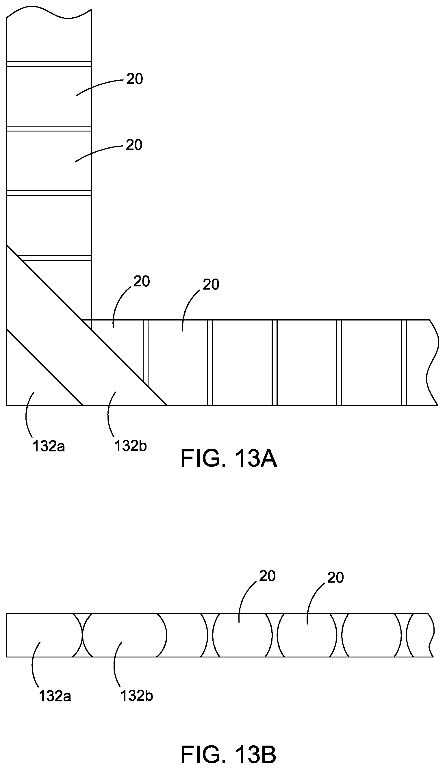
FIG. 13A is a top view of a log block row for an alternate log wall construction for a corner portion of a dwelling;
FIG. 13B is a side view of the alternate log wall construction for a corner portion of a dwelling seen in FIG. 13A;
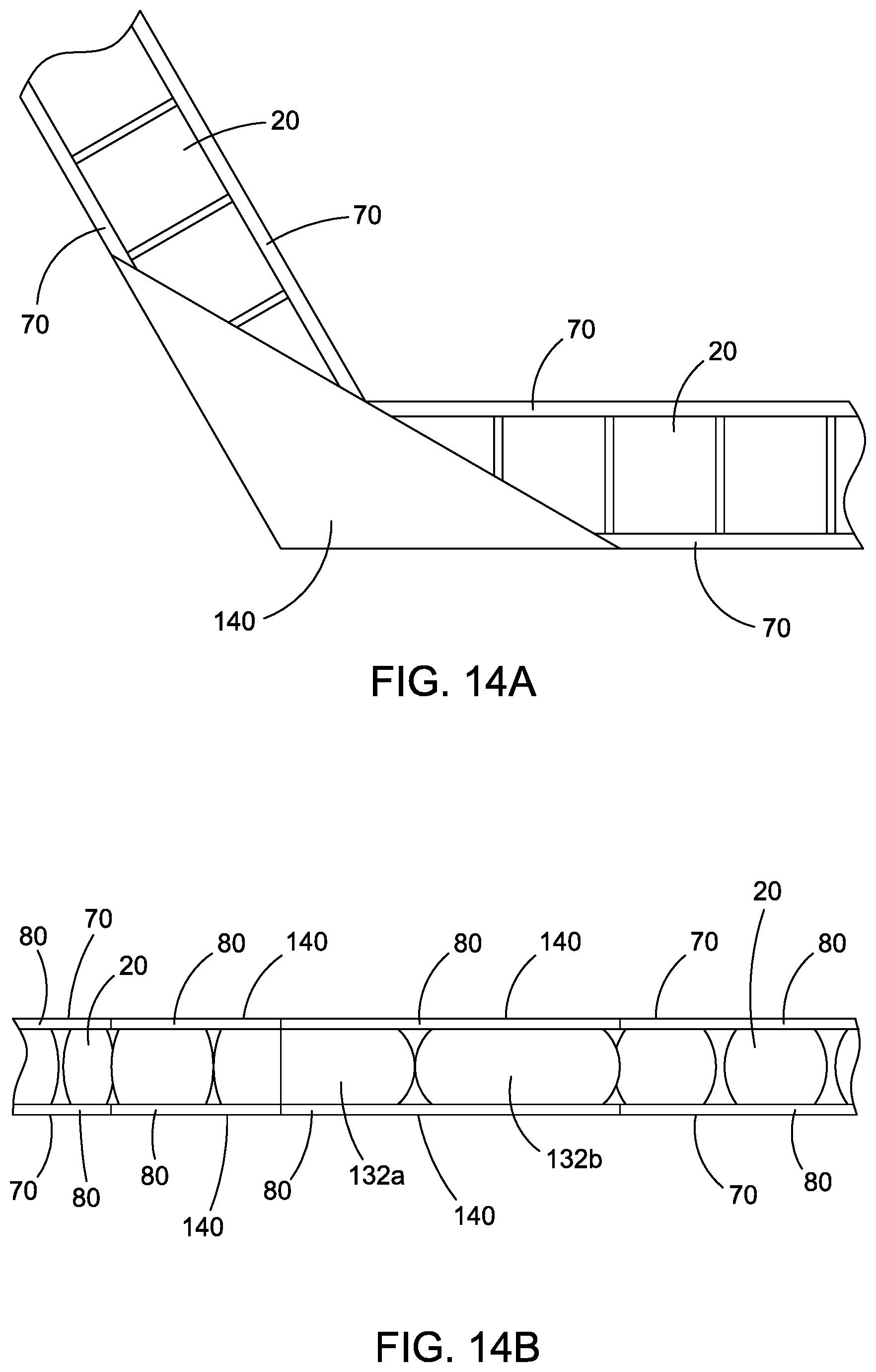
FIG. 14A is a top view of a log block row for an alternate log wall construction for a corner portion of a dwelling; and,
FIG. 14B is a side view of the alternate log wall construction for a corner portion of a dwelling seen in FIG. 14A.
The drawings show some but not all embodiments. The elements depicted in the drawings are illustrative and not necessarily to scale, and the same (or similar) reference numbers denote the same (or similar) features throughout the drawings.
DETAILED DESCRIPTION
In accordance with the practice of at least one embodiment of the invention, as seen in FIGS. 3-6 for example, there is a log wall construction 10. Construction 10 includes a plurality of log blocks 20 (seen in detail in FIGS. 1A, 1B, 2A and 2B) each having a substantially same height-dimension 22 and laid next to each other to form a log block row 50 having a log block row length 52. Each log block 20 has a top flat surface 28, a bottom flat surface 30, a front flat surface 32, a back flat surface 34, a right curved surface 36 and a left curved surface 38. Preferably, flat top and bottom surfaces 28, 30 are substantially parallel to parallel to one another. Log blocks next to each other have at least one pair of adjacent curved surfaces (36, 38) for each pair of log blocks next to each other. Construction 10 further includes a second log block row 60 of the plurality of log blocks 20 each having a second substantially same height-dimension 22 and laid next to each other to form the second log block row having a second log block row length 62 and being located on top of the first log block row 50. Still further, construction 10 includes a stringer 70 located between the log block row 50 and the second log block row 60 and separating the flat top surface 28 of each log block 20 in the log block row 50 from the flat bottom surface 30 of each log block 20 in the second log block row 60 wherever log blocks of the log block row 50 are adjacent to log blocks of the second log block row 60. The stringer extends substantially an entire distance 72 that is equivalent to both the log block row length 52 and the second log block row length 62. The stringer serves to both tie together the log blocks in a row, as well as provide a consistent spacing between log blocks in adjacent rows. Stringer height-dimension may be the same from row to row, or variations between different rows may be used, as desired.
Without being limited to a theory of understanding, surprisingly it was found this new combination of elements including the configuration and shape of the log blocks, especially as compared to full logs used to build dwellings, makes building a log wall possible unlike before. Additionally, the invention enables more easily handling building materials with no special equipment or machinery needed to do the construction. Further the log wall construction can be laid in courses to build a log wall and dwelling. Yet further, the construction 10 enables a better insulating value than a traditional log wall can provide.
Other features the invention may include are directed to the log blocks themselves, as seen in detail in FIGS. 1 and 2 collectively. For example, at least some of the log blocks may be full-sized log blocks as seen in FIGS. 1A, 1B, 3, 7-9. Alternately, at least some of the log blocks may be half-sized log blocks as seen in, for example, FIGS. 2A, 2B and 4. For such half-sized log blocks, they may have a width-dimension 24 that is at least two times as long as a height-dimension 22. The primary difference between full-sized log blocks and half-sized log blocks is their height-dimension 22, such that the half-sized log blocks right and left curved surfaces are only about a quarter of the circumference of the log used before it is cut to have flat top and bottom surfaces, or stated in corollary, the right and left curved surfaces are one-half of the log's fully curved side surfaces after the log is cut to have flat top and bottom surfaces but before it is cut in half along its width-dimension 24. Differently, for a full-sized log block it has fully curved right and left curved surfaces after the log is cut to have flat top and bottom surfaces and it has its width-dimension 24. Half-sized log blocks are generally formed from larger diameter logs and made first into full-sized log blocks that are then cut again along their center diameter to form two half-sized log blocks. While various sizes are possible, half-sized log blocks can be, for example, 4 to 10 inches in width-dimension 24, 4 to 8 inches in height-dimension 22, and 6 to 24 inches in length-dimension 26. And, while various sizes are possible, full-sized log blocks can be, for example, 6 to 20 inches in width-dimension 24, 4 to 10 inches in height-dimension 22, and 6 to 24 inches in length-dimension 26.
Another feature is directed to the material used to seal the space between adjacent log blocks. For example, at least two, preferably many, and even more preferably in some embodiments substantially all, log blocks next to each other could have at least a portion of each log block touching each other at their respective adjacent curved surfaces. Alternately or additionally, the seal between the log blocks could be: nothing (other than touching log blocks as shown), spray foam, insulation (e.g., fiberglass) stuffed or blown in, caulk, or other conventional suitable materials as would be known to one of ordinary skill in the art of building construction in conjunction with the teaching here.
In regards to securing one log block row to another log block row, and with reference to FIGS. 3-6 for example, a variety of options exist. Mere gravity may be sufficient. Alternately or additionally, one or more mechanical fastener may secure the log block row to the second log block row, for example, glue or other bonding material joined to each adjacent component of the wall and in particular at least the log blocks to stringers and stringers to log blocks. Alternately or additionally, the mechanical fastener could be like element 90 and extend in and between at least a portion of the log block row and at least a portion of the second log block row, for example, a bolt, lag screw or similar boring and securing device.
Turning to additional features the stringer may include, reference is made to FIGS. 3-6 and 10-11. The stringer can have, and preferably has, a front runner 78 with a front stringer edge 80 that is adjacent to the front surface 32 of the log blocks. The stringer may also have a back runner 82 with a back stringer edge 84 that is adjacent to the back surface 34 of the log blocks. Further, and more preferably, the front runner is separated from the back runner (as seen in most Figures, except not in FIGS. 10, 11, 14A and 14B which have a more solid stringer structure from front runner to back runner). Still more preferably, the front runner is distinct from and completely separated from the back runner. In other aspects, the stringer can have a width-dimension 74 that is at least two times as long as a height-dimension 76, see FIG. 6A for better clarity. Further, the height-dimension of the stringer may be between about 0.5 inches and about 1.5 inches, and more preferably is between about 0.75 inches and about 1.25 inches, and even more preferably is between about 0.9 inches and about 1.1 inches. Yet further, additionally or alternately, the width-dimension of the stringer may be between about 1 inch and about 3 inches, and more preferably is between about 1.5 inches and about 2.5 inches, and even more preferably is between about 1.75 inches and about 2.25 inches. The stringer may be made of wood, wire, metal sheet, plastic webbing, plastic wood or other conventional suitable materials as would be known to one of ordinary skill in the art of building construction in conjunction with the teaching here.
Considering other features of the invention, attention is directed to FIGS. 3-9 and how a wall 10 can include at least three log block rows. Further a room 100 may be formed of log block rows, as seen in FIG. 12. Also including FIGS. 10 and 11, there is seen the log wall construction of the invention as a door portion of a dwelling, a window portion of a dwelling and a floor portion of a dwelling. All this helps show how the invention can be tied into conventional structures of a dwelling as would be known to one of ordinary skill in the art of building construction in conjunction with the teaching here. For example, in the Figures and here focusing on FIGS. 5 and 6, generally starting at the roof and work our way down to the ground, there is a roof 110, tied to a top plate 112 and all this tied to wall construction 10, which sits on base plate 116 adjacent to the subfloor 114, over floor framing 120 and bounded by rim board 118. Next is foundation 122. Referring specifically to FIGS. 7 and 8 for their door and window perspective, there is seen header 124, which may be a double header like the top plate and/or other plates, over the cripples 126 (which also may be multiple layers), and both over the sill plate 128.
Referring to FIGS. 10, 11, 13A, 13B, 14A and 14B, some corner construction options are seen. The corners could have interlocking blocks 130 formed to each other as in FIGS. 10 and 11. Alternately, from a structural standpoint use of the stringers with an interlocking pattern of 45 degree angle cut log blocks 132a and 132b (and could be additional 45 degree cut blocks if needed) as seen in FIGS. 13A and 13B would add another way to ensure a stable log block row, and thereby whole wall stability, if desired. Alternatively, and referring to FIGS. 14A and 14B that show a sample 60 degree angle corner, the corner can be made structurally sound for other than 90 degree corners with the use of plywood as the stringer 140 for the corner at the substantially full to full width of the wall thickness (and could be used for 90 degrees too, if desired).
Each and every document cited in this present application, including any cross referenced or related patent or application, is incorporated in this present application in its entirety by this reference, unless expressly excluded or otherwise limited. The citation of any document is not an admission that it is prior art with respect to any embodiment disclosed in this present application or that it alone, or in any combination with any other reference or references, teaches, suggests, or discloses any such embodiment. Further, to the extent that any meaning or definition of a term in this present application conflicts with any meaning or definition of the same term in a document incorporated by reference, the meaning or definition assigned to that term in this present application governs.
The present invention includes the description, examples, embodiments, and drawings disclosed; but it is not limited to such description, examples, embodiments, or drawings. As briefly described above, the reader should assume that features of one disclosed embodiment can also be applied to all other disclosed embodiments, unless expressly indicated to the contrary. Unless expressly indicated to the contrary, the numerical parameters set forth in the present application are approximations that can vary depending on the desired properties sought to be obtained by a person of ordinary skill in the art without undue experimentation using the teachings disclosed in the present application. Modifications and other embodiments will be apparent to a person of ordinary skill in the packaging arts, and all such modifications and other embodiments are intended and deemed to be within the scope of the present invention.
* * * * *
References
D00000
D00001
D00002
D00003
D00004
D00005
D00006
D00007
D00008
XML
uspto.report is an independent third-party trademark research tool that is not affiliated, endorsed, or sponsored by the United States Patent and Trademark Office (USPTO) or any other governmental organization. The information provided by uspto.report is based on publicly available data at the time of writing and is intended for informational purposes only.
While we strive to provide accurate and up-to-date information, we do not guarantee the accuracy, completeness, reliability, or suitability of the information displayed on this site. The use of this site is at your own risk. Any reliance you place on such information is therefore strictly at your own risk.
All official trademark data, including owner information, should be verified by visiting the official USPTO website at www.uspto.gov. This site is not intended to replace professional legal advice and should not be used as a substitute for consulting with a legal professional who is knowledgeable about trademark law.