Decorative Masonry System
Fox; Daniel W.
U.S. patent application number 16/515116 was filed with the patent office on 2020-01-23 for decorative masonry system. This patent application is currently assigned to Quarry Ridge Stone, Inc.. The applicant listed for this patent is Quarry Ridge Stone, Inc.. Invention is credited to Daniel W. Fox.
| Application Number | 20200024850 16/515116 |
| Document ID | / |
| Family ID | 69160986 |
| Filed Date | 2020-01-23 |
| United States Patent Application | 20200024850 |
| Kind Code | A1 |
| Fox; Daniel W. | January 23, 2020 |
DECORATIVE MASONRY SYSTEM
Abstract
A decorative masonry system includes a first block having a first body portion and a first plurality of edges and a second block having a second body portion and a second plurality of edges. A first gutter is defined by a portion of the first plurality of edges, and a second gutter is defined by a portion of the second plurality of edges. The decorative masonry system further includes mastic configured to operably couple the first and second blocks to a substrate.
| Inventors: | Fox; Daniel W.; (Grand Rapids, MI) | ||||||||||
| Applicant: |
|
||||||||||
|---|---|---|---|---|---|---|---|---|---|---|---|
| Assignee: | Quarry Ridge Stone, Inc. Byron Center MI |
||||||||||
| Family ID: | 69160986 | ||||||||||
| Appl. No.: | 16/515116 | ||||||||||
| Filed: | July 18, 2019 |
Related U.S. Patent Documents
| Application Number | Filing Date | Patent Number | ||
|---|---|---|---|---|
| 62700549 | Jul 19, 2018 | |||
| Current U.S. Class: | 1/1 |
| Current CPC Class: | E04F 13/0873 20130101; E04F 13/0885 20130101 |
| International Class: | E04F 13/08 20060101 E04F013/08 |
Claims
1. A decorative masonry system comprising: a first block having a first body portion and a first plurality of edges, wherein the first block includes a first engagement feature; a second block having a second body portion and a second plurality of edges, wherein the second block includes a second engagement feature; a first gutter defined by a portion of the first plurality of edges; a second gutter defined by a portion of the second plurality of edges; and mastic configured to operably couple the first and second blocks to a substrate, wherein the first and second gutters are configured to receive a portion of the mastic to allow the first block to engage the second block in a surface-to-surface engagement.
2. The decorative masonry system of claim 1, wherein the first and second engagement features are integrally formed with one of the first and second body portions, respectively.
3. The decorative masonry system of claim 2, wherein the first engagement feature of the first block is configured to matingly couple with the second engagement feature of the second block.
4. The decorative masonry system of claim 1, wherein each of the first and second plurality of edges includes an edge surface positioned perpendicular to a front surface of the respective block of the first and second blocks.
5. The decorative masonry system of claim 4, wherein the edge surface of the first block is configured to align with the edge surface of the second block to form a seam that defines the surface-to-surface engagement.
6. The decorative masonry system of claim 4, wherein each of the first and second plurality of edges further includes an angled surface extending rearward of the respective edge surface.
7. The decorative masonry system of claim 6, wherein the angled surface at least partially defines the respective gutter of the first and second gutters.
8. The decorative masonry system of claim 6, wherein the angled surface is positioned at an angle from about 5.degree. to about 85.degree. measured from the edge surface.
9. The decorative masonry system of claim 1, wherein the first gutter is aligned with the second gutter to form a channel that is configured to receive a portion of the mastic.
10. A decorative masonry system comprising: a block having a body portion and a plurality of edges, wherein the body portion includes a front surface and each edge of the plurality of edges includes an edge surface and a portion of the plurality of edges includes an angled surface; a gutter defined by each angled surface of the plurality of edges; and mastic configured to operably couple a rear surface of the block to a substrate, wherein at least portion of the mastic is configured to flow into the gutter.
11. The decorative masonry system of claim 10, wherein the block includes an engagement feature integrally formed with the body portion and is surrounded by the plurality of edges.
12. The decorative masonry system of claim 10, wherein a plurality of protrusions extends from the front surface of the block, and further wherein the plurality of protrusions are configured to resemble masonry materials.
13. The decorative masonry system of claim 10, wherein the edge surface of each edge of the plurality of edges is positioned perpendicular to the front surface of the block.
14. The decorative masonry system of claim 10, wherein the angled surface of each edge of the plurality of edges is positioned at an angle from about 5.degree. to about 85.degree. measured from the respective edge surface.
15. The decorative masonry system of claim 10, wherein the angled surface of each edge of the plurality of edges is positioned at an angle from about 30.degree. to about 75.degree. measured from the respective edge surface.
16. The decorative masonry system of claim 10, wherein the edges of the plurality of edges define a continuous gutter extending about a perimeter of the block.
17. The decorative masonry system of claim 10, wherein the edge surface of the block, when positioned at a lower edge of the substrate, is configured to form a seam with a base substrate.
18. A method for making a decorative masonry system, comprising steps of: providing a mold configured to shape a decorative masonry block, the decorative masonry block having a body portion and an engagement feature, wherein a plurality of edges of the decorative masonry block define a gutter; forming a first block and a second block from a formable material using the mold; applying mastic to a rear surface of each of the first block and the second block; placing the first block on a substrate so that the mastic is positioned between the rear surface of the first block and substrate; and displacing the mastic along the plurality of edges of the body portion and the engagement feature of the first block, wherein the gutter is configured to receive displaced mastic to prevent the displaced mastic from engaging a surface-to-surface seam defined between the first and second blocks.
19. The method for making a decorative masonry system of claim 18, further comprising the steps of: placing the second block on the substrate so that the mastic is positioned between the rear surface of the second block and the substrate and the second block is aligned with the first block; and aligning one of the plurality of edges of the second block is engaged with one of the plurality of edges of the first block to define the surface-to-surface seam.
20. The method for making a decorative masonry system of claim 18, wherein the step of displacing the mastic along the plurality of edges of the body portion and the engagement feature of the first block includes applying pressure to a front surface of the first block.
Description
CROSS-REFERENCE TO RELATED APPLICATIONS
[0001] This patent application claims priority under 35 U.S.C. .sctn. 119(e) to U.S. Provisional Patent Application No. 62/700,549, entitled "DECORATIVE MASONRY SYSTEM," filed Jul. 19, 2018, the entire disclosure of which is incorporated herein by reference.
FIELD OF THE DISCLOSURE
[0002] The present disclosure generally relates to a decorative masonry system, and more specifically to a tight-seam decorative masonry system.
BACKGROUND OF THE DISCLOSURE
[0003] Currently, decorative masonry systems including faux stones require application of a mastic to the rear surface of each block in the system. When the block is pressed against a wall or surface, the mastic overflows around the edges of the stone, requiring the installer to remove the excess mastic by hand.
SUMMARY OF THE DISCLOSURE
[0004] According to some aspects of the present disclosure, a decorative masonry system includes a first block having a first body portion and a first plurality of edges. The first block includes a first engagement feature. A second block has a second body portion and a second plurality of edges. The second block includes a second engagement feature. A first gutter is defined by a portion of the first plurality of edges, and a second gutter is defined by a portion of the second plurality of edges. The decorative masonry system further includes mastic configured to operably couple the first and second blocks to a substrate. The first and second gutters are configured to receive a portion of the mastic to allow the first block to engage the second block in a surface-to-surface engagement.
[0005] According to some aspects of the present disclosure, a decorative masonry system includes a block having a body portion and a plurality of edges. The body portion includes a front surface. Each edge of the plurality of edges includes an edge surface. A portion of the plurality of edges includes an angled surface. A gutter is defined by each angled surface of the plurality of edges. The decorative masonry system further includes mastic configured to operably couple a rear surface of the block to a substrate. At least a portion of the mastic is configured to flow into the gutter.
[0006] According to some aspects of the present disclosure, a method for making a decorative masonry system includes a step of providing a mold configured to shape a decorative masonry block. The decorative masonry block has a body portion and an engagement feature. A plurality of edges of the decorative masonry block define a gutter. The method may further include a step of forming a first block and a second block from a formable material using the mold. The method may further include a step of applying mastic to a rear surface of each of the first block and the second block. The method includes a step of placing the first block on a substrate so that the mastic is positioned between the rear surface of the first block and the substrate. The method may further include a step of displacing the mastic along the plurality of edges of the body portion and the engagement feature of the first block. The gutter is configured to receive displaced mastic to prevent the displaced mastic from engaging a surface-to-surface seam defined between the first and second blocks.
[0007] These and other features, advantages, and objects of the present disclosure will be further understood and appreciated by those skilled in the art by reference to the following specification, claims, and appended drawings.
BRIEF DESCRIPTION OF THE DRAWINGS
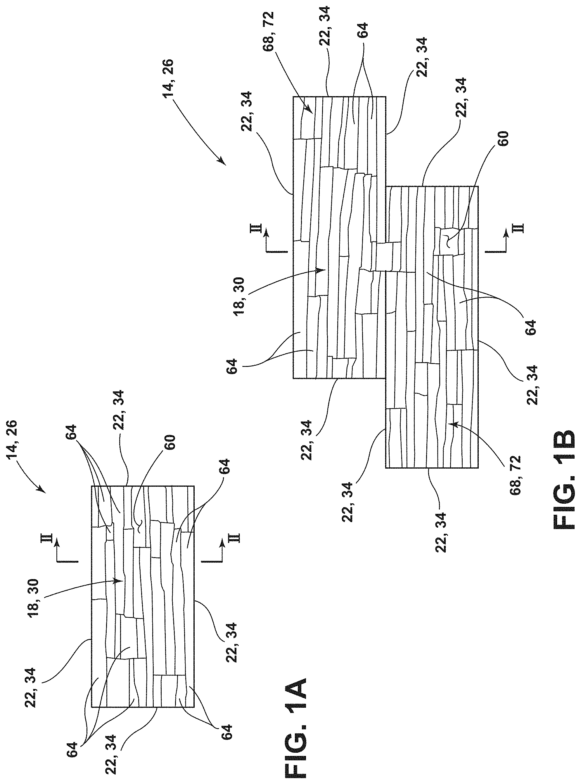
[0008] FIG. 1A is a front elevation view of a decorative masonry block, according to an aspect of the device;
[0009] FIG. 1B is a front elevation view of a decorative masonry block having an engagement feature, according to an aspect of the device;
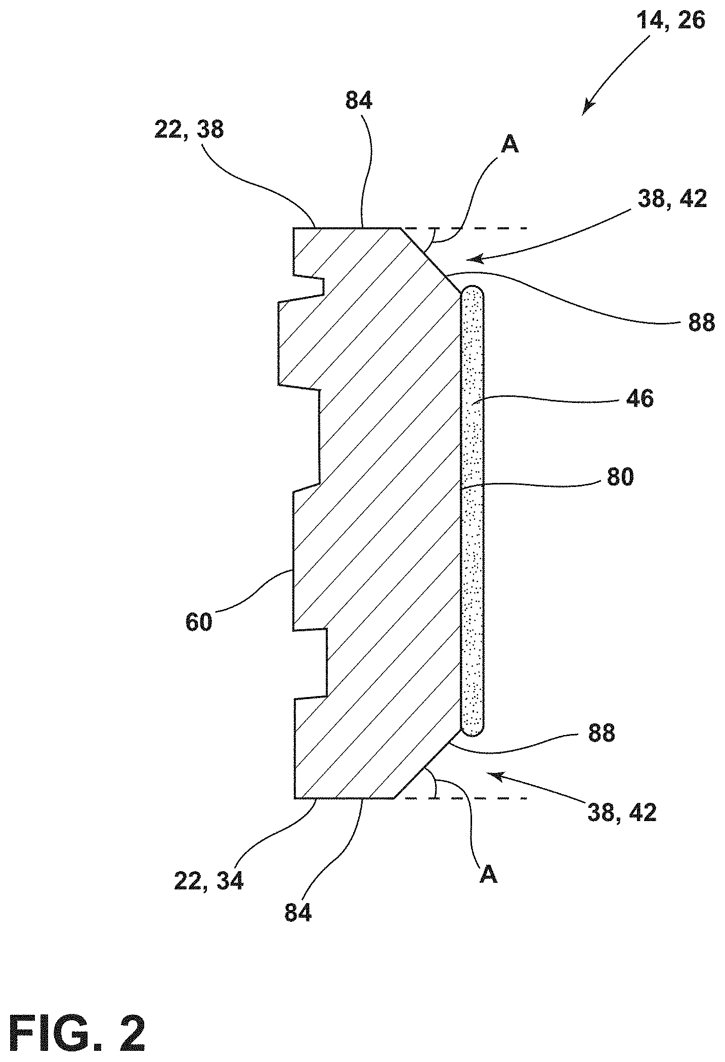
[0010] FIG. 2 is a cross-sectional view of the decorative masonry block of FIG. 1B taken along line II-II;
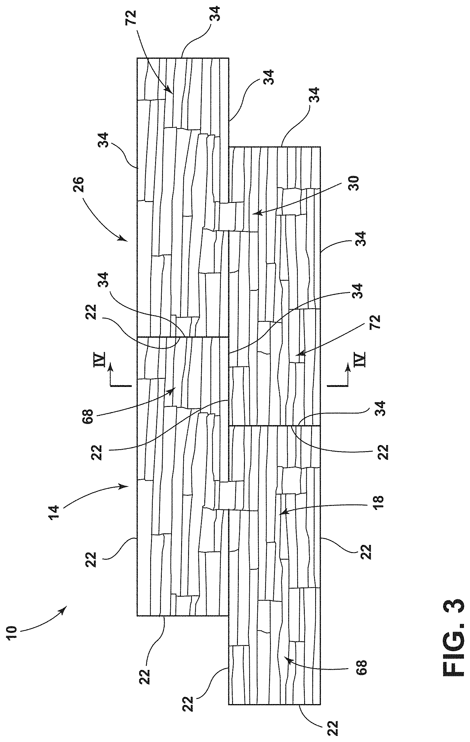
[0011] FIG. 3 is a front elevation view of a decorative masonry system comprising the decorative masonry blocks of FIG. 1B;
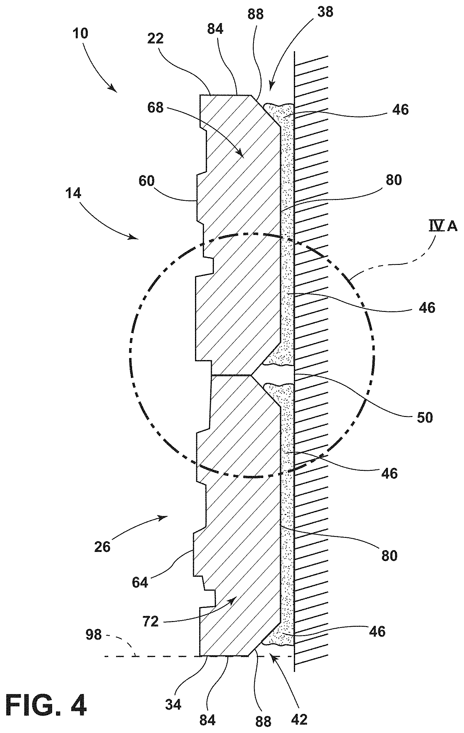
[0012] FIG. 4 is a cross-sectional view of the decorative masonry system of FIG. 3 taken along line IV-IV;
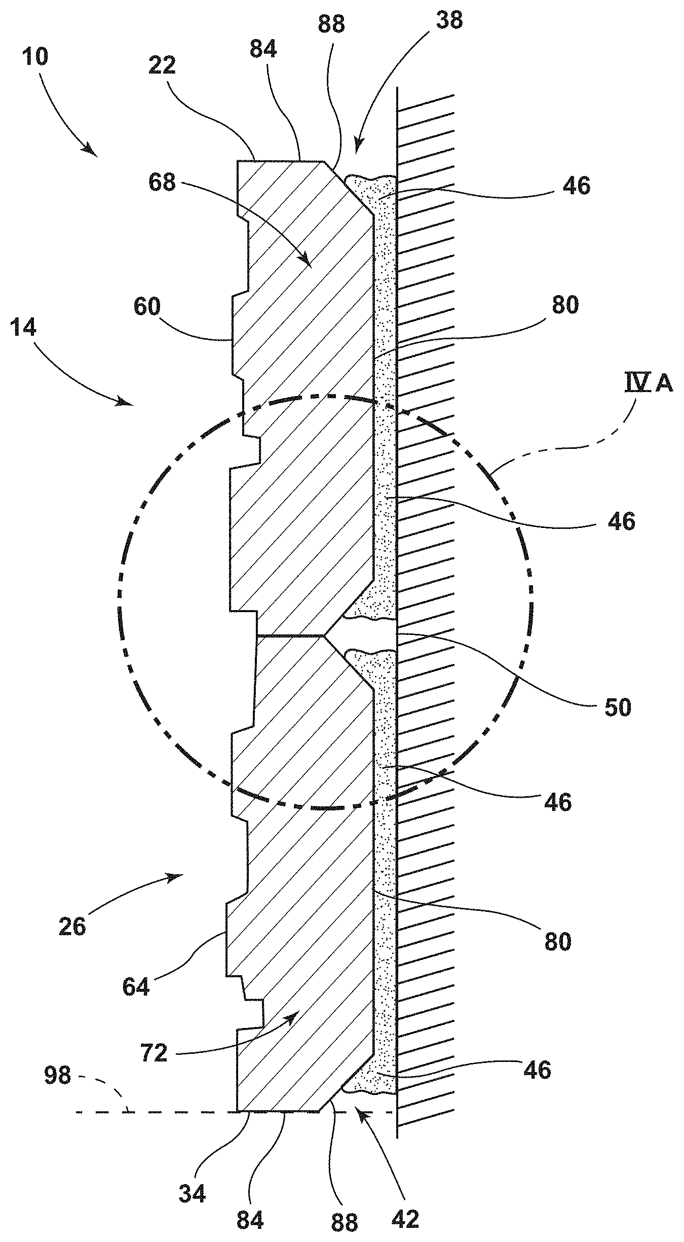
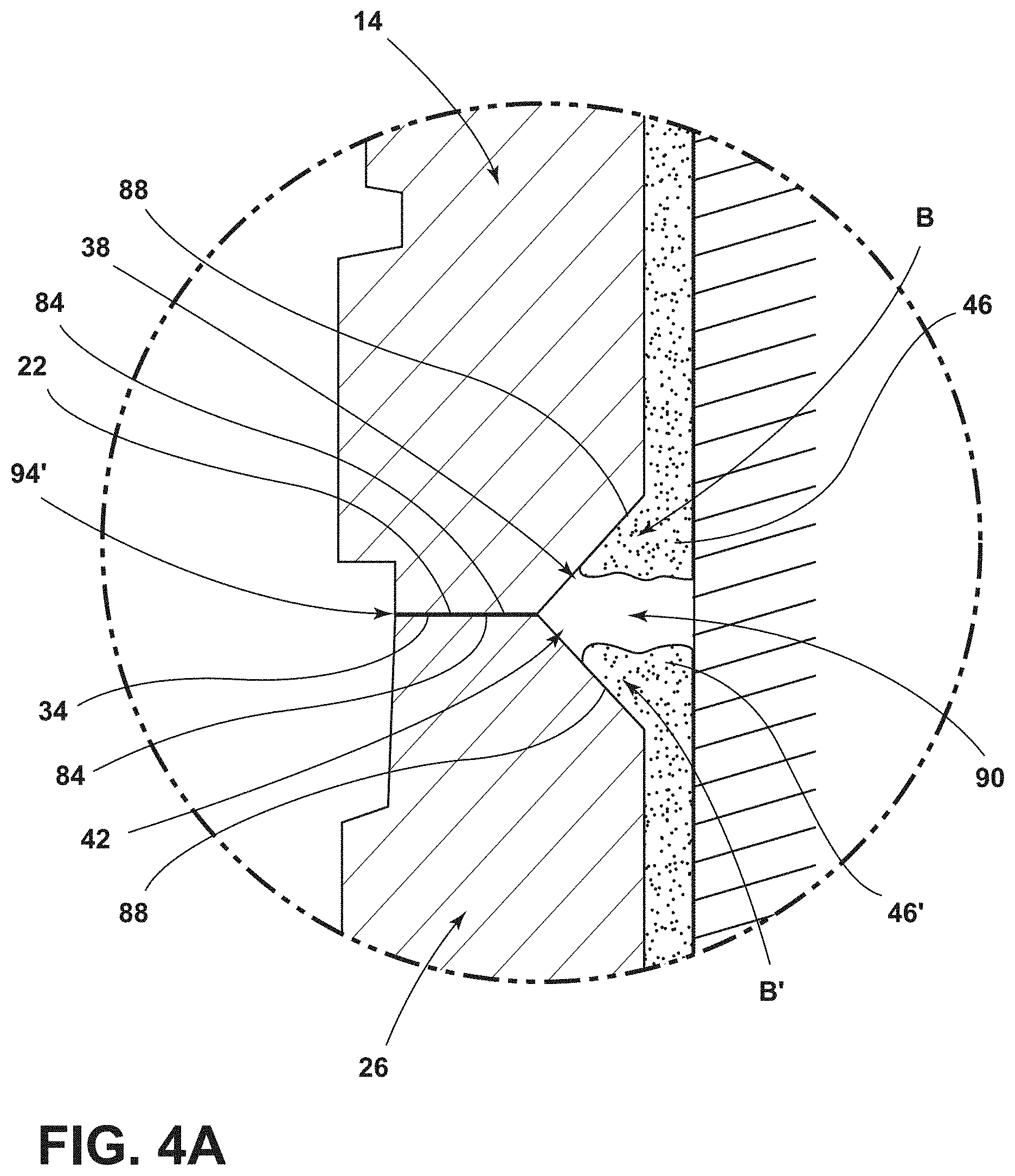
[0013] FIG. 4A is a zoomed-in view of FIG. 4 as indicated by area IVA; and
[0014] FIG. 5 is a flow diagram illustrating a method for making and assembling a decorative masonry system.
DETAILED DESCRIPTION
[0015] For purposes of description herein, the terms "upper," "lower," "right," "left," "rear," "front," "vertical," "horizontal," and derivatives thereof shall relate to the disclosure as oriented in FIGS. 1A and 1B. However, it is to be understood that the disclosure may assume various alternative orientations, except where expressly specified to the contrary. It is also to be understood that the specific devices and processes illustrated in the attached drawings, and described in the following specification are simply exemplary examples of the inventive concepts defined in the appended claims. Hence, specific dimensions and other physical characteristics relating to the examples disclosed herein are not to be considered as limiting, unless the claims expressly state otherwise.
[0016] As required, detailed examples of the present disclosure are disclosed herein. However, it is to be understood that the disclosed examples are merely exemplary of the disclosure that may be embodied in various and alternative forms. The figures are not necessarily to a detailed design and some schematics may be exaggerated or minimized to show function overview. Therefore, specific structural and functional details disclosed herein are not to be interpreted as limiting, but merely as a representative basis for teaching one skilled in the art to variously employ the present disclosure.
[0017] In this document, relational terms, such as first and second, top and bottom, and the like, are used solely to distinguish one entity or action from another entity or action, without necessarily requiring or implying any actual such relationship or order between such entities or actions. The terms "comprises," "comprising," or any other variation thereof, are intended to cover a non-exclusive inclusion, such that a process, method, article, or apparatus that comprises a list of elements does not include only those elements but may include other elements not expressly listed or inherent to such process, method, article, or apparatus. An element preceded by "comprises" does not, without more constraints, preclude the existence of additional identical elements in the process, method, article, or apparatus that comprises the element.
[0018] As used herein, the term "and/or," when used in a list of two or more items, means that any one of the listed items can be employed by itself, or any combination of two or more of the listed items can be employed. For example, if a composition is described as containing components A, B, and/or C, the composition can contain A alone; B alone; C alone; A and B in combination; A and C in combination; B and C in combination; or A, B, and C in combination.
[0019] Referring to FIGS. 1A-4A, reference numeral 10 generally relates to a decorative masonry system including a first block 14 having a first body portion 18 and a first plurality of edges 22 and a second block 26 having a second body portion 30 and a second plurality of edges 34. A first gutter 38 is defined by a portion of the first plurality of edges 22, and a second gutter 42 is defined by a portion of the second plurality of edges 34. The decorative masonry system 10 further includes mastic 46 configured to operably couple the first and second blocks 14, 26 to a substrate 50.
[0020] Referring now to FIG. 1A, according to some examples of the device, one of the first and second blocks 14, 26 is illustrated having the respective body portion 18, 30. While FIGS. 1A and 1B illustrate a single member of the decorative masonry system 10, this illustrated member is indicative of the first and second blocks 14, 26, which are substantially similar. In these FIGS. 1A and 1B, pairs of reference numbers are used to indicate some corresponding features that are present on each of the first and second blocks 14, 26. Each body portion 18, 30 includes a front surface 60 having various protrusions 64 configured to resemble various types of stone masonry. The protrusions 64 may be arranged in any pattern across the front surface 60. The body portion 18, 30 further includes the plurality of edges 22, 34 forming the perimeter of the block 14, 26. In some examples, each of the edges 22, 34 may be generally linear and positioned to form right angles (e.g., angles measuring about 90.degree.). In other examples, the edges 22, 34 may be positioned to form any other angle (rectilinear or tessellated polygons, etc.) configured to allow the block 14, 26, in a surface-to-surface engagement, to sit flush with another block 14, 26 when installed (see FIG. 3).
[0021] Referring now to FIG. 1B, according to some examples, one of the first and second blocks 14, 26 is illustrated having the respective body portion 18, 30 and one of a first and second plurality of engagement features 68, 72, respectively. These engagement features 68, 72 extend from the body portion 18, 30 and cause the first and second block 14, 26 to have a non-rectangular shape. In some examples, it is contemplated that the block 14, 26 may have only one engagement feature 68, 72. Similar to the block 14, 26 shown in FIG. 1A, the body portion 18, 30 and the plurality of engagement features 68, 72 includes the front surface 60 having the protrusions 64 configured to resemble stone masonry. The protrusions 64 may be arranged in any pattern across the front surface 60. The body portion 18, 30 and the plurality of engagement features 68, 72 further include the plurality of edges 22, 34 forming the perimeter of the block 14, 26. In some examples, each of the edges 22, 34 may be generally linear and positioned to form right angles (e.g., angles measuring about 90.degree.). In other examples, the edges 22, 34 may be positioned to form any other angle configured to allow the block 14, 26 to sit flush with another block 14, 26 when installed (see FIG. 3).
[0022] Referring now to FIG. 2, a cross-sectional view of one of the first and second blocks 14, 26 is shown having the front surface 60 and a rear surface 80. The plurality of edges 22, 34 includes an edge surface 84 and an angled surface 88. The edge surface 84 extends substantially perpendicular to the front surface 60 and is integrally formed with the angled surface 88. The angled surface 88 extends away from the edge surface 84 at a predetermined angle A towards the rear surface 80. In other words, the angled surface 84 may extend rearward of the front surface 60 toward the rear surface 80 of each of the respective blocks 14, 26. The angle A may be within a range of from about 5.degree. to about 85.degree. measured from the edge surface 84. For example, the angle A may be about 5.degree., about 10.degree., about 15.degree., about 20.degree., about 25.degree., about 30.degree., about 35.degree., about 40.degree., about 45.degree., about 50.degree., about 55.degree., about 60.degree., about 65.degree., about 70.degree., about 75.degree., about 80.degree., or about 85.degree. or any value or range of values therebetween. The angle A may be from about 30.degree. to about 75.degree., from about 50.degree. to about 65.degree., or from about 55.degree. to about 60.degree.. The angled surface 88 may be included on each edge of the plurality of edges 22, 34 in some examples, partially forming a continuous first or second gutter 38, 42 around the perimeter of the block 14, 26. In other examples, the angled surface 88 may be included on only a portion of edges of the plurality of edges 22, 34, partially forming a discontinuous first or second gutter 38, 42. Where the gutter 38, 42 is discontinuous, the angled surfaces 88 are positioned so that at least one gutter 38, 42 is present between engaging first and second blocks 14, 26. Accordingly, each seam, or engagement, 94 of the decorative masonry system 10 will typically include at least one angled surface 88 that corresponds to a gutter 38, 42. The gutter 38, 42 is configured to catch overflowing mastic 46 from the rear surface 80 without allowing the mastic 46 to reach the edge surface 84, as shown in FIG. 4. By retaining the mastic 46 in the gutters 38, 42, the mastic 46 is prevented from reaching and extending between the edge surface 84 of the first and second blocks 14, 26. In this manner, the mastic 46 does not interfere with the surface-to-surface engagement of the edge surface 84 of the first and second blocks 14, 26.
[0023] Referring now to FIG. 3, the first block 14 and the second block 26 may be positioned together so that one of the first engagement features 68 of the first block 14 is aligned with one of the second engagement features 72 of the second block 26. When the blocks 14, 26 are positioned together, the first plurality of edges 22 is flush with, and is substantially in a surface-to-surface engagement with, the second plurality of edges 34 where the blocks 14, 26 touch. This creates a seamless interface to match the seamless aesthetic of the protrusions 64 of the blocks 14, 26. It is contemplated that any number of blocks 14, 26 may be used to form the decorative masonry system 10 without departing from the scope of the present disclosure.
[0024] Referring to FIGS. 4 and 4A, a cross-sectional view of the first and second blocks 14, 26 positioned together in the decorative masonry system 10 is illustrated having the front surfaces 60 aligned. The mastic 46 is applied to the rear surface 80 of the first and second blocks 14, 26 and is trapped between the rear surfaces 80 and the substrate 50. The first engagement feature 68 of the first block 14 is coupled with the second engagement feature 72 of the second block 26 so that at least one of the first plurality of edges 22 is substantially flush with one of the second plurality of edges 34. When one of the first plurality of edges 22 is positioned flush with one of the second plurality of edges 34, the angled surfaces 88 of the respective edges 22, 34 are aligned so that the first gutter 38 is in communication with the second gutter 42 to form a channel 90. The channel 90 is configured to receive mastic 46 that leaks or is displaced from the application of the blocks 14, 26 to the substrate 50. Further, when one of the first plurality of edges 22 is positioned flush with one of the second plurality of edges 34, the edge surfaces 84 of the respective edges 22, 34 are positioned to form a tight and close fitting engagement 94, providing a tight and close fitting relationship between the blocks 14, 26 with surface-to-surface engagement. In various examples, the edge surfaces 84 of one of the blocks 14, 26 may be positioned to form a tight and close fitting engagement 94 with a second, or base, substrate 98 such as, for example, a top surface of a horizontal foundation wall. This engagement may service to hide, conceal, or otherwise obscure the location of the seam 94 between the first and second blocks 14, 26. It will be understood that the tight and close fitting engagement 94 may be in any location along the engagement 94 around the blocks 14, 26 in order to form the desired design with the blocks 14, 26 for the decorative masonry system 10.
[0025] To assemble the decorative masonry system 10, mastic 46 is applied to the rear surface 80 of each of the first and second blocks 14, 26. The first and second blocks 14, 26 are placed against the substrate 50, trapping the mastic 46 between the rear surface 80 and the substrate 50. When pressure is applied to the respective front surfaces 60 to secure the first and second blocks 14, 26 to the substrate 50, the mastic 46 overflows along arrows B into the respective first or second gutter 38, 42. The gutters 38, 42 trap the mastic 46 overflowing without damaging the surface-to-surface engagement of the decorative masonry system 10.
[0026] When assembling conventional masonry systems, mastic overflows when the blocks are applied to the substrate. The mastic then collects on the edges of the blocks and must be manually removed. The inaccuracy of the removal may cause gaps between the blocks, causing seams to show and ruining the illusion of an authentic stone facade. The removal is also labor intensive and costly to do properly to achieve the seamless look.
[0027] With the proposed decorative masonry system 10, the blocks 14, 26 can be molded for any type of stone facade (e.g., brick, flagstone, etc.) to provide a seamless appearance. The relief pattern of the blocks 14, 26 further increases the seamless aesthetic, creating an illusion of individual stacked pieces of stone masonry.
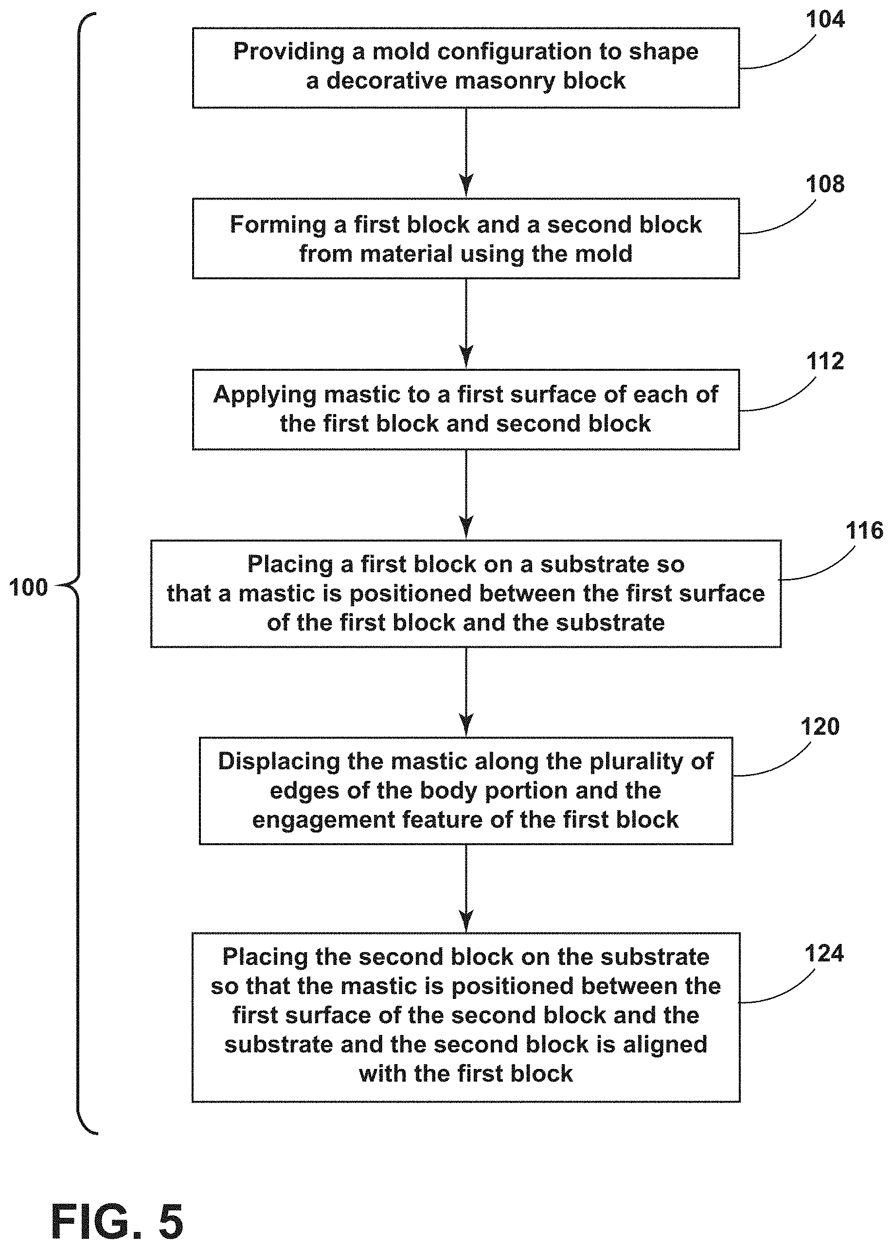
[0028] Referring now to FIG. 5, with continued reference to FIGS. 1A-4A, a method 100 for making a decorative masonry system 10 is provided that comprises a step 104 of providing a mold configured to shape a decorative masonry block 14, 26. The decorative masonry block 14, 26 has a body portion 18, 30 and an engagement feature 68, 72. A plurality of edges 22, 34 of the decorative masonry block 14, 26 defines a gutter 38, 42. The method 100 may further include a step 108 of forming a first block 14 and a second block 26 from material using the mold. Next is a step 112 of applying mastic 46 to rear surface 80 of each of the first block 14 and the second block 26. The method 100 may further include a step 116 of placing the first block 14 on a substrate 50 so that the mastic 46 is positioned between the rear surface 80 of the first block 14 and substrate 50. By pressing the first and second blocks 14, 26 against the substrate 50, the mastic 46 is displaced around portions of the first and second blocks 14, 26 and toward or into the gutters 38, 42 defined by the edges 22 (step 120). Next is a step 124 of placing the second block 26 on the substrate 50 so that the mastic 46 is positioned between the rear surface 80 of the second block 26 and the substrate 50 and the second block 26 is aligned with the first block 14. One of the plurality of edges 34 of the second block 26 is engaged with one of the plurality of edges 22 of the first block 14 in surface-to-surface contact. It is contemplated that, although the steps are listed in a particular order, they may be performed in any order or with two or more steps being performed concurrently without departing from the scope of the present disclosure.
[0029] The decorative masonry system 10 disclosed herein provides a smaller rear surface 80 so to provide for the angled surface 88 to form the gutters 38, 42, and, in turn, the channel 90 for accumulating excess mastic 46. This mastic 46 can spread when the first and second blocks 14, 26 are pressed against the substrate 50. By accumulating this excess mastic 46 in the channel 90, the seam 94 between the first and second blocks 14, 26 remains a surface-to-surface engagement 94 that conceals, hides, and obscures the presence of the location of the engagement 94 for the decorative masonry system 10.
[0030] For purposes of this disclosure, the term "coupled" (in all of its forms, couple, coupling, coupled, etc.) generally means the joining of two components (electrical or mechanical) directly or indirectly to one another. Such joining may be stationary in nature or movable in nature. Such joining may be achieved with the two components (electrical or mechanical) and any additional intermediate members being integrally formed as a single unitary body with one another or with the two components. Such joining may be permanent in nature or may be removable or releasable in nature unless otherwise stated.
[0031] Furthermore, any arrangement of components to achieve the same functionality is effectively "associated" such that the desired functionality is achieved. Hence, any two components herein combined to achieve a particular functionality can be seen as "associated with" each other such that the desired functionality is achieved, irrespective of architectures or intermedial components. Likewise, any two components so associated can also be viewed as being "operably connected" or "operably coupled" to each other to achieve the desired functionality, and any two components capable of being so associated can also be viewed as being "operably coupleable" to each other to achieve the desired functionality. Some examples of operably coupleable include, but are not limited to, physically mateable and/or physically interacting components and/or wirelessly interactable and/or wirelessly interacting components and/or logically interacting and/or logically interactable components. Furthermore, it will be understood that a component preceding the term "of the" may be disposed at any practicable location (e.g., on, within, and/or externally disposed from the vehicle) such that the component may function in any manner described herein.
[0032] As used herein, the term "about" means that amounts, sizes, formulations, parameters, and other quantities and characteristics are not and need not be exact, but may be approximate and/or larger or smaller, as desired, reflecting tolerances, conversion factors, rounding off, measurement error and the like, and other factors known to those of skill in the art. When the term "about" is used in describing a value or an end-point of a range, the disclosure should be understood to include the specific value or end-point referred to. Whether or not a numerical value or end-point of a range in the specification recites "about," the numerical value or end-point of a range is intended to include two embodiments: one modified by "about," and one not modified by "about." It will be further understood that the end-points of each of the ranges are significant both in relation to the other end-point, and independently of the other end-point.
[0033] It is also important to note that the construction and arrangement of the elements of the disclosure as shown in the exemplary examples is illustrative only. Although only a few examples of the present innovations have been described in detail in this disclosure, those skilled in the art who review this disclosure will readily appreciate that many modifications are possible (e.g., variations in sizes, dimensions, structures, shapes and proportions of the various elements, values of parameters, mounting arrangements, use of materials, colors, orientations, etc.) without materially departing from the novel teachings and advantages of the subject matter recited. For example, elements shown as integrally formed may be constructed of multiple parts or elements shown as multiple parts may be integrally formed, the operation of the interfaces may be reversed or otherwise varied, the length or width of the structures and/or members or connectors or other elements of the system may be varied, the nature or number of adjustment positions provided between the elements may be varied. It should be noted that the elements and/or assemblies of the system might be constructed from any of a wide variety of materials that provide sufficient strength or durability, in any of a wide variety of colors, textures, and combinations. Accordingly, all such modifications are intended to be included within the scope of the present innovations. Other substitutions, modifications, changes, and omissions may be made in the design, operating conditions, and arrangement of the desired and other exemplary examples without departing from the spirit of the present innovations.
* * * * *
D00000
D00001
D00002
D00003
D00004
D00005
D00006
XML
uspto.report is an independent third-party trademark research tool that is not affiliated, endorsed, or sponsored by the United States Patent and Trademark Office (USPTO) or any other governmental organization. The information provided by uspto.report is based on publicly available data at the time of writing and is intended for informational purposes only.
While we strive to provide accurate and up-to-date information, we do not guarantee the accuracy, completeness, reliability, or suitability of the information displayed on this site. The use of this site is at your own risk. Any reliance you place on such information is therefore strictly at your own risk.
All official trademark data, including owner information, should be verified by visiting the official USPTO website at www.uspto.gov. This site is not intended to replace professional legal advice and should not be used as a substitute for consulting with a legal professional who is knowledgeable about trademark law.