Theft detection and prevention in a power generation system
Sella , et al. April 6, 2
U.S. patent number 10,969,412 [Application Number 15/834,929] was granted by the patent office on 2021-04-06 for theft detection and prevention in a power generation system. This patent grant is currently assigned to Solaredge Technologies Ltd.. The grantee listed for this patent is Solaredge Technologies Ltd.. Invention is credited to Meir Adest, Yaron Binder, Amir Fishelov, Yoav Galin, Meir Gazit, Lior Handelsman, Guy Sella, Ilan Yoscovich.


View All Diagrams
| United States Patent | 10,969,412 |
| Sella , et al. | April 6, 2021 |
Theft detection and prevention in a power generation system
Abstract
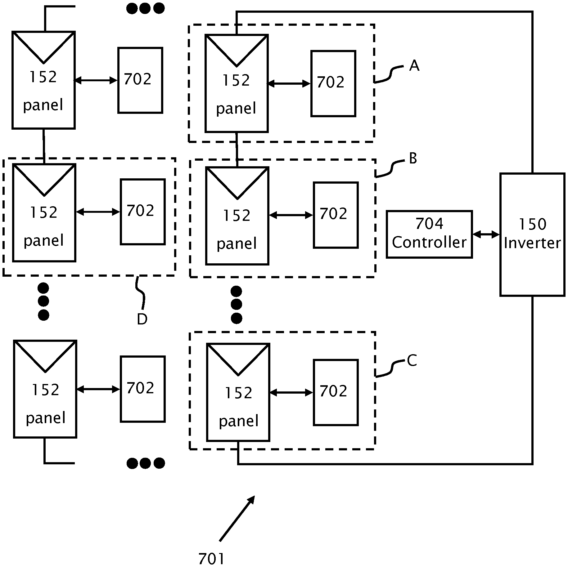
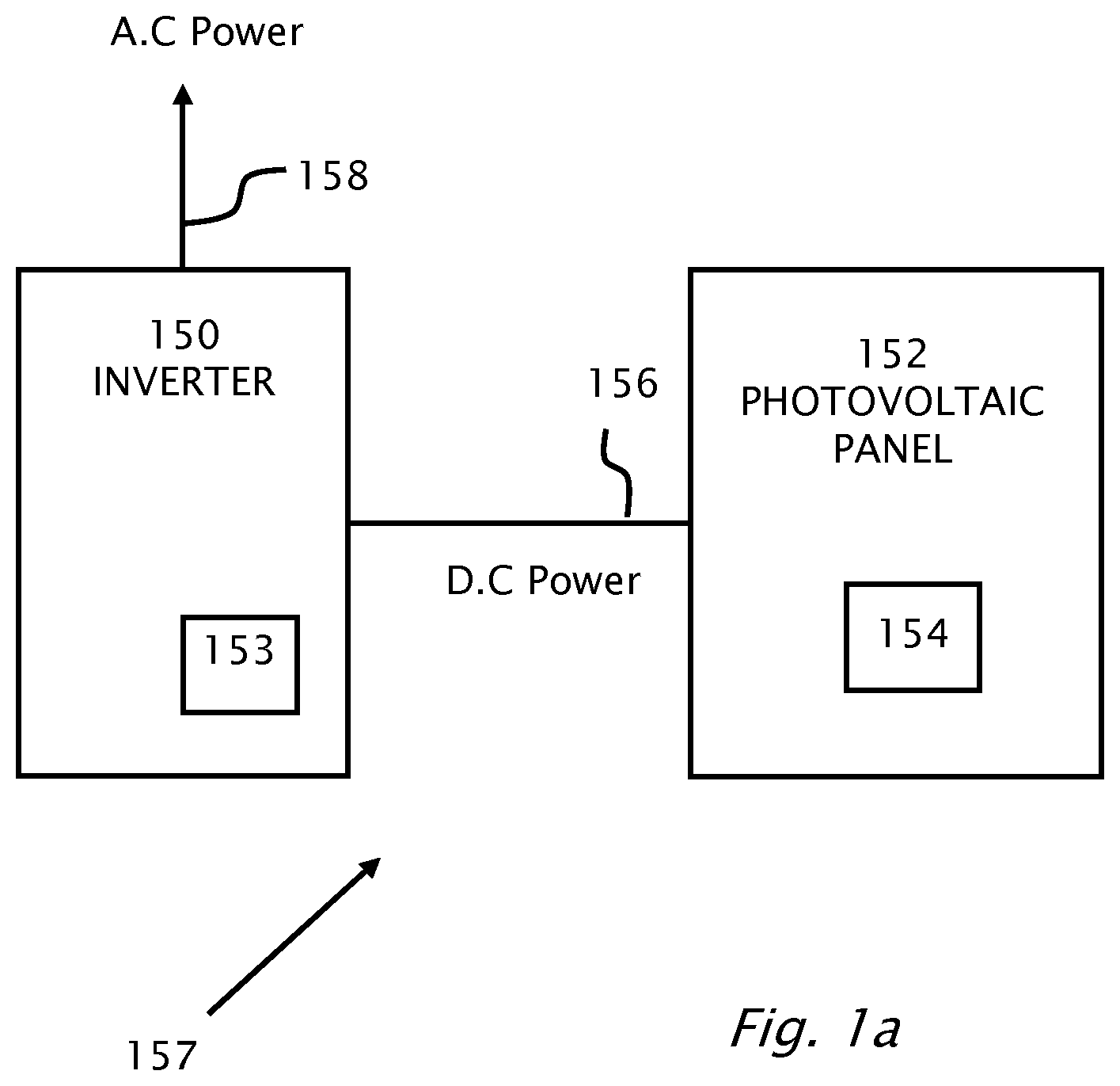
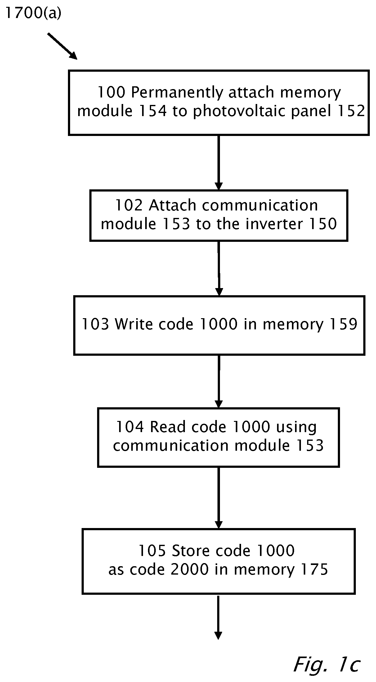
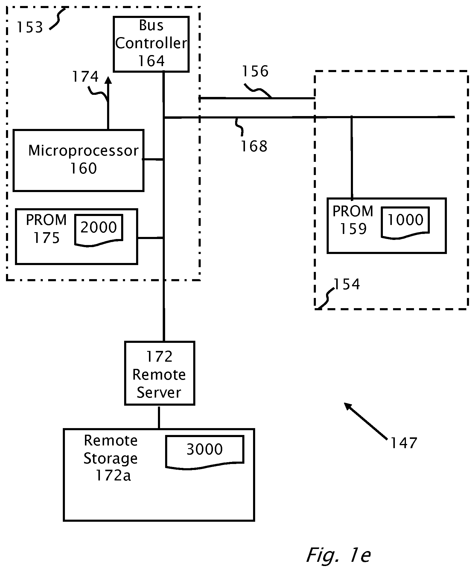
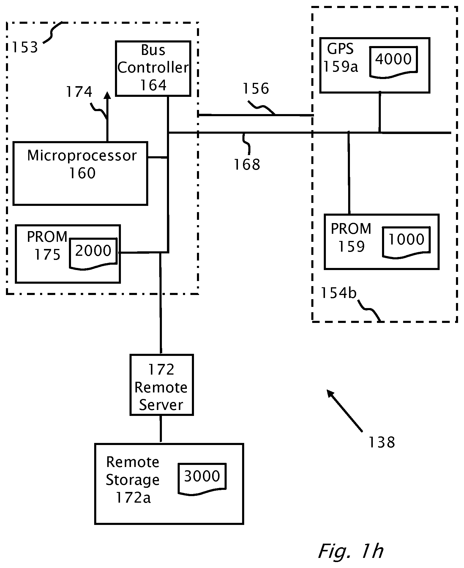
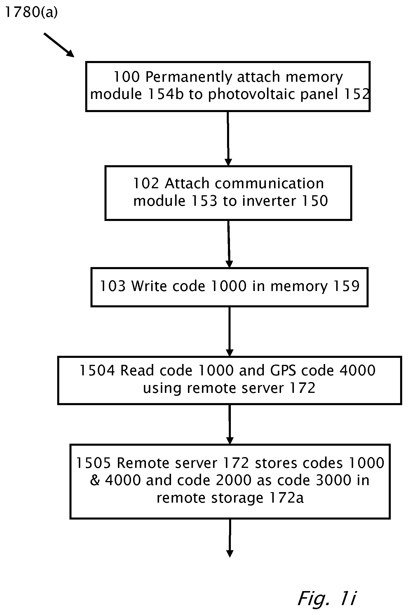
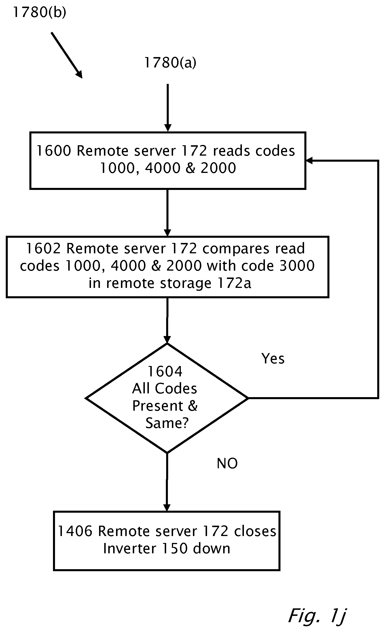
A system for generation of electrical power including an inverter connected to a photovoltaic source including a theft prevention and detection feature. A first memory is permanently attached to the photovoltaic source. The first memory is configured to store a first code. A second memory is attached to the inverter. The second memory configured to store a second code. During manufacture or installation of the system, the first code is stored in the first memory attached to the photovoltaic source. The second code based on the first code is stored in the second memory. Prior to operation of the inverter, the first code is compared to the second code and based on the comparison; the generation of the electrical power is enabled or disabled.
| Inventors: | Sella; Guy (Bitan Aharon, IL), Adest; Meir (Raanana, IL), Gazit; Meir (Ashkelon, IL), Handelsman; Lior (Givatayim, IL), Yoscovich; Ilan (Ramat-Gan, IL), Fishelov; Amir (Tel Aviv, IL), Binder; Yaron (Shoham, IL), Galin; Yoav (Raanana, IL) | ||||||||||
|---|---|---|---|---|---|---|---|---|---|---|---|
| Applicant: |
|
||||||||||
| Assignee: | Solaredge Technologies Ltd.
(Herzeliya, IL) |
||||||||||
| Family ID: | 1000005469460 | ||||||||||
| Appl. No.: | 15/834,929 | ||||||||||
| Filed: | December 7, 2017 |
Prior Publication Data
| Document Identifier | Publication Date | |
|---|---|---|
| US 20180210016 A1 | Jul 26, 2018 | |
Related U.S. Patent Documents
| Application Number | Filing Date | Patent Number | Issue Date | ||
|---|---|---|---|---|---|
| 14582363 | Dec 24, 2014 | 9869701 | |||
| 12788066 | Feb 3, 2015 | 8947194 | |||
| 61180940 | May 26, 2009 | ||||
| Current U.S. Class: | 1/1 |
| Current CPC Class: | G01R 17/02 (20130101); G01R 27/26 (20130101); G08B 13/1409 (20130101) |
| Current International Class: | G01R 17/02 (20060101); G08B 13/14 (20060101); G01R 27/26 (20060101) |
| Field of Search: | ;340/539.1,571.2,568.1,568.2,531,533,3.1 ;136/244,243 |
References Cited [Referenced By]
U.S. Patent Documents
| 2367925 | January 1945 | Brown |
| 2586804 | February 1952 | Fluke |
| 2758219 | August 1956 | Miller |
| 2852721 | September 1958 | Harders et al. |
| 2958171 | November 1960 | Deckers |
| 3369210 | February 1968 | Manickella |
| 3392326 | July 1968 | Lamberton |
| 3496029 | February 1970 | King et al. |
| 3566143 | February 1971 | Paine et al. |
| 3643564 | February 1972 | Uchiyama |
| 3696286 | October 1972 | Ule |
| 3740652 | June 1973 | Burgener |
| 3958136 | May 1976 | Schroeder |
| 4060757 | November 1977 | McMurray |
| 4101816 | July 1978 | Shepter |
| 4104687 | August 1978 | Zulaski |
| 4127797 | November 1978 | Perper |
| 4129788 | December 1978 | Chavannes |
| 4129823 | December 1978 | van der Pool et al. |
| 4146785 | March 1979 | Neale |
| 4161771 | July 1979 | Bates |
| 4171861 | October 1979 | Hohorst |
| 4183079 | January 1980 | Wachi |
| 4257087 | March 1981 | Cuk |
| 4296461 | October 1981 | Mallory et al. |
| 4321581 | March 1982 | Tappeiner et al. |
| 4324225 | April 1982 | Trihey |
| 4327318 | April 1982 | Kwon et al. |
| 4346341 | August 1982 | Blackburn et al. |
| 4363040 | December 1982 | Inose |
| 4367557 | January 1983 | Stern et al. |
| 4375662 | March 1983 | Baker |
| 4384321 | May 1983 | Rippel |
| 4404472 | September 1983 | Steigerwald |
| 4412142 | October 1983 | Ragonese et al. |
| 4452867 | June 1984 | Conforti |
| 4453207 | June 1984 | Paul |
| 4460232 | July 1984 | Sotolongo |
| 4470213 | September 1984 | Thompson |
| 4479175 | October 1984 | Gille et al. |
| 4481654 | November 1984 | Daniels et al. |
| 4488136 | December 1984 | Hansen et al. |
| 4526553 | July 1985 | Guerrero |
| 4533986 | August 1985 | Jones |
| 4545997 | October 1985 | Wong et al. |
| 4549254 | October 1985 | Kissel |
| 4554502 | November 1985 | Rohatyn |
| 4554515 | November 1985 | Burson et al. |
| 4580090 | April 1986 | Bailey et al. |
| 4591965 | May 1986 | Dickerson |
| 4598330 | July 1986 | Woodworth |
| 4602322 | July 1986 | Merrick |
| 4604567 | August 1986 | Chetty |
| 4611090 | September 1986 | Catella et al. |
| 4623753 | November 1986 | Feldman et al. |
| 4626983 | December 1986 | Harada et al. |
| 4631565 | December 1986 | Tihanyi |
| 4637677 | January 1987 | Barkus |
| 4639844 | January 1987 | Gallios et al. |
| 4641042 | February 1987 | Miyazawa |
| 4641079 | February 1987 | Kato et al. |
| 4644458 | February 1987 | Harafuji et al. |
| 4649334 | March 1987 | Nakajima |
| 4652770 | March 1987 | Kumano |
| 4683529 | July 1987 | Bucher, II |
| 4685040 | August 1987 | Steigerwald et al. |
| 4686617 | August 1987 | Colton |
| 4706181 | November 1987 | Mercer |
| 4719553 | January 1988 | Hinckley |
| 4720667 | January 1988 | Lee et al. |
| 4720668 | January 1988 | Lee et al. |
| 4736151 | April 1988 | Dishner |
| 4746879 | May 1988 | Ma et al. |
| 4772994 | September 1988 | Harada et al. |
| 4783728 | November 1988 | Hoffman |
| 4797803 | January 1989 | Carroll |
| 4819121 | April 1989 | Saito et al. |
| RE33057 | September 1989 | Clegg et al. |
| 4864213 | September 1989 | Kido |
| 4868379 | September 1989 | West |
| 4873480 | October 1989 | Lafferty |
| 4888063 | December 1989 | Powell |
| 4888702 | December 1989 | Gerken et al. |
| 4899246 | February 1990 | Tripodi |
| 4899269 | February 1990 | Rouzies |
| 4903851 | February 1990 | Slough |
| 4906859 | March 1990 | Kobayashi et al. |
| 4910518 | March 1990 | Kim et al. |
| 4951117 | August 1990 | Kasai |
| 4978870 | December 1990 | Chen et al. |
| 4987360 | January 1991 | Thompson |
| 5001415 | March 1991 | Watkinson |
| 5027051 | June 1991 | Lafferty |
| 5027059 | June 1991 | de Montgolfier et al. |
| 5045988 | September 1991 | Gritter et al. |
| 5081558 | January 1992 | Mahler |
| 5097196 | March 1992 | Schoneman |
| 5138422 | August 1992 | Fujii et al. |
| 5143556 | September 1992 | Matlin |
| 5144222 | September 1992 | Herbert |
| 5155670 | October 1992 | Brian |
| 5191519 | March 1993 | Kawakami |
| 5196781 | March 1993 | Jamieson et al. |
| 5210519 | May 1993 | Moore |
| 5235266 | August 1993 | Schaffrin |
| 5237194 | August 1993 | Takahashi |
| 5268832 | December 1993 | Kandatsu |
| 5280133 | January 1994 | Nath |
| 5280232 | January 1994 | Kohl et al. |
| 5287261 | February 1994 | Ehsani |
| 5289361 | February 1994 | Vinciarelli |
| 5289998 | March 1994 | Bingley et al. |
| 5327071 | July 1994 | Frederick et al. |
| 5329222 | July 1994 | Gyugyi et al. |
| 5345375 | September 1994 | Mohan |
| 5379209 | January 1995 | Goff |
| 5381327 | January 1995 | Yan |
| 5391235 | February 1995 | Inoue |
| 5402060 | March 1995 | Erisman |
| 5404059 | April 1995 | Loffler |
| 5412558 | May 1995 | Sakurai et al. |
| 5413313 | May 1995 | Mutterlein et al. |
| 5428286 | June 1995 | Kha |
| 5446645 | August 1995 | Shirahama et al. |
| 5460546 | October 1995 | Kunishi et al. |
| 5472614 | December 1995 | Rossi |
| 5477091 | December 1995 | Fiorina et al. |
| 5493154 | February 1996 | Smith et al. |
| 5497289 | March 1996 | Sugishima et al. |
| 5501083 | March 1996 | Kim |
| 5504415 | April 1996 | Podrazhansky et al. |
| 5504418 | April 1996 | Ashley |
| 5504449 | April 1996 | Prentice |
| 5513075 | April 1996 | Capper et al. |
| 5517378 | May 1996 | Asplund et al. |
| 5530335 | June 1996 | Decker et al. |
| 5539238 | July 1996 | Malhi |
| 5548504 | August 1996 | Takehara |
| 5563780 | October 1996 | Goad |
| 5565855 | October 1996 | Knibbe |
| 5566022 | October 1996 | Segev |
| 5576941 | November 1996 | Nguyen et al. |
| 5580395 | December 1996 | Yoshioka et al. |
| 5585749 | December 1996 | Pace et al. |
| 5604430 | February 1997 | Decker et al. |
| 5616913 | April 1997 | Litterst |
| 5631534 | May 1997 | Lewis |
| 5636107 | June 1997 | Lu et al. |
| 5644212 | July 1997 | Takahashi |
| 5644219 | July 1997 | Kurokawa |
| 5646501 | July 1997 | Fishman et al. |
| 5648731 | July 1997 | Decker et al. |
| 5654740 | August 1997 | Schulha |
| 5659465 | August 1997 | Flack et al. |
| 5677833 | October 1997 | Bingley |
| 5684385 | November 1997 | Guyonneau et al. |
| 5686766 | November 1997 | Tamechika |
| 5696439 | December 1997 | Presti et al. |
| 5703390 | December 1997 | Itoh |
| 5708576 | January 1998 | Jones et al. |
| 5719758 | February 1998 | Nakata et al. |
| 5722057 | February 1998 | Wu |
| 5726505 | March 1998 | Yamada et al. |
| 5726615 | March 1998 | Bloom |
| 5731603 | March 1998 | Nakagawa et al. |
| 5734258 | March 1998 | Esser |
| 5734259 | March 1998 | Sisson et al. |
| 5734565 | March 1998 | Mueller et al. |
| 5747967 | May 1998 | Muljadi et al. |
| 5751120 | May 1998 | Zeitler et al. |
| 5773963 | June 1998 | Blanc et al. |
| 5777515 | July 1998 | Kimura |
| 5777858 | July 1998 | Rodulfo |
| 5780092 | July 1998 | Agbo et al. |
| 5793184 | August 1998 | O'Connor |
| 5798631 | August 1998 | Spee et al. |
| 5801519 | September 1998 | Midya et al. |
| 5804894 | September 1998 | Leeson et al. |
| 5812045 | September 1998 | Ishikawa et al. |
| 5814970 | September 1998 | Schmidt |
| 5821734 | October 1998 | Faulk |
| 5822186 | October 1998 | Bull et al. |
| 5838148 | November 1998 | Kurokami et al. |
| 5847549 | December 1998 | Dodson, III |
| 5859772 | January 1999 | Hilbert |
| 5869956 | February 1999 | Nagao et al. |
| 5873738 | February 1999 | Shimada et al. |
| 5886882 | March 1999 | Rodulfo |
| 5886890 | March 1999 | Ishida et al. |
| 5892354 | April 1999 | Nagao et al. |
| 5898585 | April 1999 | Sirichote et al. |
| 5903138 | May 1999 | Hwang et al. |
| 5905645 | May 1999 | Cross |
| 5917722 | June 1999 | Singh |
| 5919314 | July 1999 | Kim |
| 5923100 | July 1999 | Lukens et al. |
| 5923158 | July 1999 | Kurokami et al. |
| 5929614 | July 1999 | Copple |
| 5930128 | July 1999 | Dent |
| 5930131 | July 1999 | Feng |
| 5932994 | August 1999 | Jo et al. |
| 5933327 | August 1999 | Leighton et al. |
| 5945806 | August 1999 | Faulk |
| 5946206 | August 1999 | Shimizu et al. |
| 5949668 | September 1999 | Schweighofer |
| 5955885 | September 1999 | Kurokami et al. |
| 5959438 | September 1999 | Jovanovic et al. |
| 5961739 | October 1999 | Osborne |
| 5963010 | October 1999 | Hayashi et al. |
| 5963078 | October 1999 | Wallace |
| 5982253 | November 1999 | Perrin et al. |
| 5986909 | November 1999 | Hammond et al. |
| 5990659 | November 1999 | Frannhagen |
| 6002290 | December 1999 | Avery et al. |
| 6002603 | December 1999 | Carver |
| 6008971 | December 1999 | Duba et al. |
| 6021052 | February 2000 | Unger et al. |
| 6031736 | February 2000 | Takehara et al. |
| 6037720 | March 2000 | Wong et al. |
| 6038148 | March 2000 | Farrington et al. |
| 6046470 | April 2000 | Williams et al. |
| 6046919 | April 2000 | Madenokouji et al. |
| 6050779 | April 2000 | Nagao et al. |
| 6058035 | May 2000 | Madenokouji et al. |
| 6064086 | May 2000 | Nakagawa et al. |
| 6078511 | June 2000 | Fasullo et al. |
| 6081104 | June 2000 | Kern |
| 6082122 | July 2000 | Madenokouji et al. |
| 6087738 | July 2000 | Hammond |
| 6091329 | July 2000 | Newman |
| 6093885 | July 2000 | Takehara et al. |
| 6094129 | July 2000 | Baiatu |
| 6101073 | August 2000 | Takehara |
| 6105317 | August 2000 | Tomiuchi et al. |
| 6111188 | August 2000 | Kurokami et al. |
| 6111391 | August 2000 | Cullen |
| 6111767 | August 2000 | Handleman |
| 6130458 | October 2000 | Takagi et al. |
| 6150739 | November 2000 | Baumgartl et al. |
| 6151234 | November 2000 | Oldenkamp |
| 6163086 | December 2000 | Choo |
| 6166455 | December 2000 | Li |
| 6166527 | December 2000 | Dwelley et al. |
| 6169678 | January 2001 | Kondo et al. |
| 6175219 | January 2001 | Imamura et al. |
| 6175512 | January 2001 | Hagihara et al. |
| 6191456 | February 2001 | Stoisiek et al. |
| 6219623 | April 2001 | Wills |
| 6225793 | May 2001 | Dickmann |
| 6255360 | July 2001 | Domschke et al. |
| 6255804 | July 2001 | Herniter et al. |
| 6256234 | July 2001 | Keeth et al. |
| 6259234 | July 2001 | Perol |
| 6262558 | July 2001 | Weinberg |
| 6268559 | July 2001 | Yamawaki |
| 6274804 | August 2001 | Psyk et al. |
| 6275016 | August 2001 | Ivanov |
| 6281485 | August 2001 | Siri |
| 6285572 | September 2001 | Onizuka et al. |
| 6292379 | September 2001 | Edevold et al. |
| 6297621 | October 2001 | Hui et al. |
| 6301128 | October 2001 | Jang et al. |
| 6304065 | October 2001 | Wittenbreder |
| 6307749 | October 2001 | Daanen et al. |
| 6311137 | October 2001 | Kurokami et al. |
| 6316716 | November 2001 | Hilgrath |
| 6320769 | November 2001 | Kurokami et al. |
| 6329808 | December 2001 | Enguent |
| 6331670 | December 2001 | Takehara et al. |
| 6339538 | January 2002 | Handleman |
| 6344612 | February 2002 | Kuwahara et al. |
| 6346451 | February 2002 | Simpson et al. |
| 6348781 | February 2002 | Midya et al. |
| 6350944 | February 2002 | Sherif et al. |
| 6351130 | February 2002 | Preiser et al. |
| 6369461 | April 2002 | Jungreis et al. |
| 6369462 | April 2002 | Siri |
| 6380719 | April 2002 | Underwood et al. |
| 6396170 | May 2002 | Laufenberg et al. |
| 6396239 | May 2002 | Benn et al. |
| 6400579 | June 2002 | Cuk |
| 6425248 | July 2002 | Tonomura et al. |
| 6429546 | August 2002 | Ropp et al. |
| 6429621 | August 2002 | Arai |
| 6433522 | August 2002 | Siri |
| 6433978 | August 2002 | Neiger et al. |
| 6441597 | August 2002 | Lethellier |
| 6445599 | September 2002 | Nguyen |
| 6448489 | September 2002 | Kimura et al. |
| 6452814 | September 2002 | Wittenbreder |
| 6465910 | October 2002 | Young et al. |
| 6465931 | October 2002 | Knowles et al. |
| 6469919 | October 2002 | Bennett |
| 6472254 | October 2002 | Cantarini et al. |
| 6483203 | November 2002 | McCormack |
| 6493246 | December 2002 | Suzui et al. |
| 6501362 | December 2002 | Hoffman et al. |
| 6507176 | January 2003 | Wittenbreder, Jr. |
| 6509712 | January 2003 | Landis |
| 6512444 | January 2003 | Morris, Jr. et al. |
| 6515215 | February 2003 | Mimura |
| 6519165 | February 2003 | Koike |
| 6528977 | March 2003 | Arakawa |
| 6531848 | March 2003 | Chitsazan et al. |
| 6545211 | April 2003 | Mimura |
| 6548205 | April 2003 | Leung et al. |
| 6560131 | May 2003 | vonBrethorst |
| 6587051 | July 2003 | Takehara et al. |
| 6590793 | July 2003 | Nagao et al. |
| 6590794 | July 2003 | Carter |
| 6593520 | July 2003 | Kondo et al. |
| 6593521 | July 2003 | Kobayashi |
| 6600100 | July 2003 | Ho et al. |
| 6603672 | August 2003 | Deng et al. |
| 6608468 | August 2003 | Nagase |
| 6611130 | August 2003 | Chang |
| 6611441 | August 2003 | Kurokami et al. |
| 6628011 | September 2003 | Droppo et al. |
| 6633824 | October 2003 | Dollar, II |
| 6636431 | October 2003 | Seki et al. |
| 6650031 | November 2003 | Goldack |
| 6650560 | November 2003 | MacDonald et al. |
| 6653549 | November 2003 | Matsushita et al. |
| 6655987 | December 2003 | Higashikozono et al. |
| 6657419 | December 2003 | Renyolds |
| 6664762 | December 2003 | Kutkut |
| 6672018 | January 2004 | Shingleton |
| 6678174 | January 2004 | Suzui et al. |
| 6690590 | February 2004 | Stamenic et al. |
| 6693327 | February 2004 | Priefert et al. |
| 6693781 | February 2004 | Kroker |
| 6709291 | March 2004 | Wallace et al. |
| 6724593 | April 2004 | Smith |
| 6731136 | May 2004 | Knee |
| 6738692 | May 2004 | Schienbein et al. |
| 6744643 | June 2004 | Luo et al. |
| 6750391 | June 2004 | Bower et al. |
| 6765315 | July 2004 | Hammerstrom et al. |
| 6768047 | July 2004 | Chang et al. |
| 6768180 | July 2004 | Salama et al. |
| 6788033 | September 2004 | Vinciarelli |
| 6788146 | September 2004 | Forejt et al. |
| 6795318 | September 2004 | Haas et al. |
| 6800964 | October 2004 | Beck |
| 6801442 | October 2004 | Suzui et al. |
| 6807069 | October 2004 | Nieminen et al. |
| 6809942 | October 2004 | Madenokouji et al. |
| 6810339 | October 2004 | Wills |
| 6812396 | November 2004 | Makita et al. |
| 6828503 | December 2004 | Yoshikawa et al. |
| 6828901 | December 2004 | Birchfield et al. |
| 6837739 | January 2005 | Gorringe et al. |
| 6838611 | January 2005 | Kondo et al. |
| 6838856 | January 2005 | Raichle |
| 6842354 | January 2005 | Tallam et al. |
| 6844739 | January 2005 | Kasai et al. |
| 6850074 | February 2005 | Adams et al. |
| 6856102 | February 2005 | Lin et al. |
| 6882131 | April 2005 | Takada et al. |
| 6888728 | May 2005 | Takagi et al. |
| 6894911 | May 2005 | Telefus et al. |
| 6897370 | May 2005 | Kondo et al. |
| 6914418 | July 2005 | Sung |
| 6919714 | July 2005 | Delepaut |
| 6927955 | August 2005 | Suzui et al. |
| 6933627 | August 2005 | Wilhelm |
| 6933714 | August 2005 | Fasshauer et al. |
| 6936995 | August 2005 | Kapsokavathis et al. |
| 6940735 | September 2005 | Deng et al. |
| 6949843 | September 2005 | Dubovsky |
| 6950323 | September 2005 | Achleitner et al. |
| 6963147 | November 2005 | Kurokami et al. |
| 6966184 | November 2005 | Toyomura et al. |
| 6970365 | November 2005 | Turchi |
| 6980783 | December 2005 | Liu et al. |
| 6984967 | January 2006 | Notman |
| 6984970 | January 2006 | Capel |
| 6987444 | January 2006 | Bub et al. |
| 6996741 | February 2006 | Pittelkow et al. |
| 7030597 | April 2006 | Bruno et al. |
| 7031176 | April 2006 | Kotsopoulos et al. |
| 7038430 | May 2006 | Itabashi et al. |
| 7042195 | May 2006 | Tsunetsugu et al. |
| 7045991 | May 2006 | Nakamura et al. |
| 7046531 | May 2006 | Zocchi et al. |
| 7053506 | May 2006 | Alonso et al. |
| 7061211 | June 2006 | Satoh et al. |
| 7061214 | June 2006 | Mayega et al. |
| 7064967 | June 2006 | Ichinose et al. |
| 7068017 | June 2006 | Willner et al. |
| 7072194 | July 2006 | Nayar et al. |
| 7078883 | July 2006 | Chapman et al. |
| 7079406 | July 2006 | Kurokami et al. |
| 7087332 | August 2006 | Harris |
| 7088595 | August 2006 | Nino |
| 7090509 | August 2006 | Gilliland et al. |
| 7091707 | August 2006 | Cutler |
| 7097516 | August 2006 | Werner et al. |
| 7099169 | August 2006 | West et al. |
| 7126053 | October 2006 | Kurokami et al. |
| 7126294 | October 2006 | Minami et al. |
| 7138786 | November 2006 | Ishigaki et al. |
| 7142997 | November 2006 | Widner |
| 7148669 | December 2006 | Maksimovic et al. |
| 7150938 | December 2006 | Munshi et al. |
| 7158359 | January 2007 | Bertele et al. |
| 7158395 | January 2007 | Deng et al. |
| 7161082 | January 2007 | Matsushita et al. |
| 7174973 | February 2007 | Lysaght |
| 7183667 | February 2007 | Colby et al. |
| 7193872 | March 2007 | Siri |
| 7202653 | April 2007 | Pai |
| 7208674 | April 2007 | Aylaian |
| 7218541 | May 2007 | Price et al. |
| 7248946 | July 2007 | Bashaw et al. |
| 7256566 | August 2007 | Bhavaraju et al. |
| 7259474 | August 2007 | Blanc |
| 7262979 | August 2007 | Wai et al. |
| 7276886 | October 2007 | Kinder et al. |
| 7277304 | October 2007 | Stancu et al. |
| 7281141 | October 2007 | Elkayam et al. |
| 7282814 | October 2007 | Jacobs |
| 7282924 | October 2007 | Wittner |
| 7291036 | November 2007 | Daily et al. |
| RE39976 | January 2008 | Schiff et al. |
| 7315052 | January 2008 | Alter |
| 7319313 | January 2008 | Dickerson et al. |
| 7324361 | January 2008 | Siri |
| 7336004 | February 2008 | Lai |
| 7336056 | February 2008 | Dening |
| 7339287 | March 2008 | Jepsen et al. |
| 7348802 | March 2008 | Kasanyal et al. |
| 7352154 | April 2008 | Cook |
| 7361952 | April 2008 | Miura et al. |
| 7371963 | May 2008 | Suenaga et al. |
| 7372712 | May 2008 | Stancu et al. |
| 7385380 | June 2008 | Ishigaki et al. |
| 7385833 | June 2008 | Keung |
| 7388348 | June 2008 | Mattichak |
| 7394237 | July 2008 | Chou et al. |
| 7405117 | July 2008 | Zuniga et al. |
| 7414870 | August 2008 | Rottger et al. |
| 7420354 | September 2008 | Cutler |
| 7420815 | September 2008 | Love |
| 7432691 | October 2008 | Cutler |
| 7435134 | October 2008 | Lenox |
| 7435897 | October 2008 | Russell |
| 7443052 | October 2008 | Wendt et al. |
| 7443152 | October 2008 | Utsunomiya |
| 7450401 | November 2008 | Iida |
| 7456510 | November 2008 | Ito et al. |
| 7456523 | November 2008 | Kobayashi |
| 7463500 | December 2008 | West |
| 7466566 | December 2008 | Fukumoto |
| 7471014 | December 2008 | Lum et al. |
| 7471524 | December 2008 | Batarseh et al. |
| 7479774 | January 2009 | Wai et al. |
| 7482238 | January 2009 | Sung |
| 7485987 | February 2009 | Mori et al. |
| 7495419 | February 2009 | Ju |
| 7504811 | March 2009 | Watanabe et al. |
| 7518346 | April 2009 | Prexl et al. |
| 7538451 | May 2009 | Nomoto |
| 7560915 | July 2009 | Ito et al. |
| 7589437 | September 2009 | Henne et al. |
| 7595616 | September 2009 | Prexl et al. |
| 7596008 | September 2009 | Iwata et al. |
| 7599200 | October 2009 | Tomonaga |
| 7600349 | October 2009 | Liebendorfer |
| 7602080 | October 2009 | Hadar et al. |
| 7602626 | October 2009 | Iwata et al. |
| 7605498 | October 2009 | Ledenev et al. |
| 7612283 | November 2009 | Toyomura et al. |
| 7615981 | November 2009 | Wong et al. |
| 7626834 | December 2009 | Chisenga et al. |
| 7646116 | January 2010 | Batarseh et al. |
| 7649434 | January 2010 | Xu et al. |
| 7701083 | April 2010 | Savage |
| 7709727 | May 2010 | Roehrig et al. |
| 7719140 | May 2010 | Ledenev et al. |
| 7723865 | May 2010 | Kitanaka |
| 7733069 | June 2010 | Toyomura et al. |
| 7748175 | July 2010 | Liebendorfer |
| 7759575 | July 2010 | Jones et al. |
| 7763807 | July 2010 | Richter |
| 7772716 | August 2010 | Shaver, II et al. |
| 7780472 | August 2010 | Lenox |
| 7782031 | August 2010 | Qiu et al. |
| 7783389 | August 2010 | Yamada et al. |
| 7787273 | August 2010 | Lu et al. |
| 7804282 | September 2010 | Bertele |
| 7807919 | October 2010 | Powell et al. |
| 7808125 | October 2010 | Sachdeva et al. |
| 7812592 | October 2010 | Prior et al. |
| 7812701 | October 2010 | Lee et al. |
| 7821225 | October 2010 | Chou et al. |
| 7824189 | November 2010 | Lauermann et al. |
| 7839022 | November 2010 | Wolfs |
| 7843085 | November 2010 | Ledenev et al. |
| 7864497 | January 2011 | Quardt et al. |
| 7868599 | January 2011 | Rahman et al. |
| 7880334 | February 2011 | Evans et al. |
| 7883808 | February 2011 | Norimatsu et al. |
| 7884278 | February 2011 | Powell et al. |
| 7893346 | February 2011 | Nachamkin et al. |
| 7898112 | March 2011 | Powell et al. |
| 7900361 | March 2011 | Adest et al. |
| 7906007 | March 2011 | Gibson et al. |
| 7906870 | March 2011 | Ohm |
| 7919952 | April 2011 | Fahrenbruch |
| 7919953 | April 2011 | Porter et al. |
| 7925552 | April 2011 | Tarbell et al. |
| 7944191 | May 2011 | Xu |
| 7945413 | May 2011 | Krein |
| 7948221 | May 2011 | Watanabe et al. |
| 7952897 | May 2011 | Nocentini et al. |
| 7960650 | June 2011 | Richter et al. |
| 7960950 | June 2011 | Glovinsky |
| 7969133 | June 2011 | Zhang et al. |
| 7977810 | July 2011 | Choi et al. |
| 8003885 | August 2011 | Richter et al. |
| 8004113 | August 2011 | Sander et al. |
| 8004116 | August 2011 | Ledenev et al. |
| 8004117 | August 2011 | Adest et al. |
| 8004866 | August 2011 | Bucella et al. |
| 8013472 | September 2011 | Adest et al. |
| 8018748 | September 2011 | Leonard |
| 8035249 | October 2011 | Shaver, II et al. |
| 8039730 | October 2011 | Hadar et al. |
| 8049363 | November 2011 | McLean et al. |
| 8050804 | November 2011 | Kernahan |
| 8058747 | November 2011 | Avrutsky et al. |
| 8058752 | November 2011 | Erickson, Jr. et al. |
| 8067855 | November 2011 | Mumtaz et al. |
| 8077437 | December 2011 | Mumtaz et al. |
| 8080986 | December 2011 | Lai et al. |
| 8089780 | January 2012 | Mochikawa et al. |
| 8089785 | January 2012 | Rodriguez |
| 8090548 | January 2012 | Abdennadher et al. |
| 8093756 | January 2012 | Porter et al. |
| 8093757 | January 2012 | Wolfs |
| 8097818 | January 2012 | Gerull et al. |
| 8098055 | January 2012 | Avrutsky et al. |
| 8102074 | January 2012 | Hadar et al. |
| 8102144 | January 2012 | Capp et al. |
| 8111052 | February 2012 | Glovinsky |
| 8116103 | February 2012 | Zacharias et al. |
| 8138631 | March 2012 | Allen et al. |
| 8138914 | March 2012 | Wong et al. |
| 8139335 | March 2012 | Quardt et al. |
| 8139382 | March 2012 | Zhang et al. |
| 8148849 | April 2012 | Zanarini et al. |
| 8158877 | April 2012 | Klein et al. |
| 8169252 | May 2012 | Fahrenbruch et al. |
| 8179147 | May 2012 | Dargatz et al. |
| 8184460 | May 2012 | O'Brien et al. |
| 8188610 | May 2012 | Scholte-Wassink |
| 8204709 | June 2012 | Presher, Jr. |
| 8212408 | July 2012 | Fishman |
| 8212409 | July 2012 | Bettenwort et al. |
| 8248804 | August 2012 | Han et al. |
| 8271599 | September 2012 | Eizips et al. |
| 8274172 | September 2012 | Hadar et al. |
| 8279644 | October 2012 | Zhang et al. |
| 8284574 | October 2012 | Chapman et al. |
| 8289183 | October 2012 | Foss |
| 8289742 | October 2012 | Adest et al. |
| 8294451 | October 2012 | Hasenfus |
| 8299773 | October 2012 | Jang et al. |
| 8304932 | November 2012 | Ledenev et al. |
| 8310101 | November 2012 | Amaratunga et al. |
| 8310102 | November 2012 | Raju |
| 8314375 | November 2012 | Arditi et al. |
| 8324921 | December 2012 | Adest et al. |
| 8325059 | December 2012 | Rozenboim |
| 8344548 | January 2013 | Stern |
| 8369113 | February 2013 | Rodriguez |
| 8378656 | February 2013 | de Rooij et al. |
| 8379418 | February 2013 | Falk |
| 8391031 | March 2013 | Garrity |
| 8391032 | March 2013 | Garrity et al. |
| 8395366 | March 2013 | Uno |
| 8405248 | March 2013 | Mumtaz et al. |
| 8405349 | March 2013 | Kikinis et al. |
| 8405367 | March 2013 | Chisenga et al. |
| 8410359 | April 2013 | Richter |
| 8410889 | April 2013 | Garrity et al. |
| 8410950 | April 2013 | Takehara et al. |
| 8415552 | April 2013 | Hadar et al. |
| 8415937 | April 2013 | Hester |
| 8427009 | April 2013 | Shaver, II et al. |
| 8436592 | May 2013 | Saitoh |
| 8461809 | June 2013 | Rodriguez |
| 8466789 | June 2013 | Muhlberger et al. |
| 8472220 | June 2013 | Garrity et al. |
| 8473250 | June 2013 | Adest et al. |
| 8509032 | August 2013 | Rakib |
| 8526205 | September 2013 | Garrity |
| 8531055 | September 2013 | Adest et al. |
| 8542512 | September 2013 | Garrity |
| 8570017 | October 2013 | Perichon et al. |
| 8581441 | November 2013 | Rotzoll et al. |
| 8587151 | November 2013 | Adest et al. |
| 8618692 | December 2013 | Adest et al. |
| 8624443 | January 2014 | Mumtaz |
| 8653689 | February 2014 | Rozenboim |
| 8669675 | March 2014 | Capp et al. |
| 8670255 | March 2014 | Gong et al. |
| 8674548 | March 2014 | Mumtaz |
| 8674668 | March 2014 | Chisenga et al. |
| 8686333 | April 2014 | Arditi et al. |
| 8710351 | April 2014 | Robbins |
| 8751053 | June 2014 | Hadar et al. |
| 8773236 | July 2014 | Makhota et al. |
| 8791598 | July 2014 | Jain |
| 8809699 | August 2014 | Funk |
| 8811047 | August 2014 | Rodriguez |
| 8816535 | August 2014 | Adest et al. |
| 8823212 | September 2014 | Garrity et al. |
| 8823218 | September 2014 | Hadar et al. |
| 8823342 | September 2014 | Williams |
| 8835748 | September 2014 | Frolov et al. |
| 8841916 | September 2014 | Avrutsky |
| 8853886 | October 2014 | Avrutsky et al. |
| 8854193 | October 2014 | Makhota et al. |
| 8859884 | October 2014 | Dunton et al. |
| 8860241 | October 2014 | Hadar et al. |
| 8860246 | October 2014 | Hadar et al. |
| 8878563 | November 2014 | Robbins |
| 8917156 | December 2014 | Garrity et al. |
| 8922061 | December 2014 | Arditi |
| 8933321 | January 2015 | Hadar et al. |
| 8934269 | January 2015 | Garrity |
| 8963375 | February 2015 | DeGraaff |
| 8963378 | February 2015 | Fornage et al. |
| 8972765 | March 2015 | Krolak et al. |
| 9130401 | September 2015 | Adest et al. |
| 9257848 | February 2016 | Coccia et al. |
| 9291696 | March 2016 | Adest et al. |
| 9397497 | July 2016 | Ledenev |
| 9401664 | July 2016 | Perreault et al. |
| 9407161 | August 2016 | Adest et al. |
| 9466737 | October 2016 | Ledenev |
| 9660527 | May 2017 | Glovinski |
| 9673630 | June 2017 | Ledenev et al. |
| 9819178 | November 2017 | Gazit et al. |
| 9831916 | November 2017 | Behrends |
| 9843193 | December 2017 | Getsla |
| 9923516 | March 2018 | Har-Shai et al. |
| 9991717 | June 2018 | Rowe et al. |
| 10032939 | July 2018 | Ledenev et al. |
| 2001/0000957 | May 2001 | Birchfield et al. |
| 2001/0023703 | September 2001 | Kondo et al. |
| 2001/0032664 | October 2001 | Takehara et al. |
| 2001/0034982 | November 2001 | Nagao et al. |
| 2001/0035180 | November 2001 | Kimura et al. |
| 2001/0048605 | December 2001 | Kurokami et al. |
| 2001/0050102 | December 2001 | Matsumi et al. |
| 2001/0054881 | December 2001 | Watanabe |
| 2002/0002040 | January 2002 | Kline et al. |
| 2002/0014262 | February 2002 | Matsushita et al. |
| 2002/0017900 | February 2002 | Takeda et al. |
| 2002/0034083 | March 2002 | Ayyanar et al. |
| 2002/0038667 | April 2002 | Kondo et al. |
| 2002/0041505 | April 2002 | Suzui et al. |
| 2002/0044473 | April 2002 | Toyomura et al. |
| 2002/0047309 | April 2002 | Droppo et al. |
| 2002/0047693 | April 2002 | Chang |
| 2002/0056089 | May 2002 | Houston |
| 2002/0063552 | May 2002 | Arakawa |
| 2002/0063625 | May 2002 | Takehara et al. |
| 2002/0078991 | June 2002 | Nagao et al. |
| 2002/0080027 | June 2002 | Conley |
| 2002/0085397 | July 2002 | Suzui et al. |
| 2002/0113689 | August 2002 | Gehlot et al. |
| 2002/0118559 | August 2002 | Kurokami et al. |
| 2002/0127980 | September 2002 | Amanullah et al. |
| 2002/0134567 | September 2002 | Rasmussen et al. |
| 2002/0148497 | October 2002 | Sasaoka et al. |
| 2002/0149950 | October 2002 | Takebayashi |
| 2002/0162585 | November 2002 | Sugawara et al. |
| 2002/0165458 | November 2002 | Carter et al. |
| 2002/0177401 | November 2002 | Judd et al. |
| 2002/0179140 | December 2002 | Toyomura |
| 2002/0180408 | December 2002 | McDaniel et al. |
| 2002/0190696 | December 2002 | Darshan |
| 2003/0002303 | January 2003 | Riggio et al. |
| 2003/0025594 | February 2003 | Akiyama et al. |
| 2003/0038615 | February 2003 | Elbanhawy |
| 2003/0047207 | March 2003 | Aylaian |
| 2003/0058593 | March 2003 | Bertele et al. |
| 2003/0058662 | March 2003 | Baudelot et al. |
| 2003/0066076 | April 2003 | Minahan |
| 2003/0066555 | April 2003 | Hui et al. |
| 2003/0075211 | April 2003 | Makita et al. |
| 2003/0080741 | May 2003 | LeRow et al. |
| 2003/0085621 | May 2003 | Potega |
| 2003/0090233 | May 2003 | Browe |
| 2003/0090246 | May 2003 | Shenai et al. |
| 2003/0094931 | May 2003 | Renyolds |
| 2003/0107352 | June 2003 | Downer et al. |
| 2003/0111103 | June 2003 | Bower et al. |
| 2003/0116154 | June 2003 | Butler et al. |
| 2003/0121514 | July 2003 | Davenport et al. |
| 2003/0140960 | July 2003 | Baum et al. |
| 2003/0156439 | August 2003 | Ohmichi et al. |
| 2003/0164695 | September 2003 | Fasshauer et al. |
| 2003/0185026 | October 2003 | Matsuda et al. |
| 2003/0193821 | October 2003 | Krieger et al. |
| 2003/0201674 | October 2003 | Droppo et al. |
| 2003/0214274 | November 2003 | Lethellier |
| 2003/0223257 | December 2003 | Onoe |
| 2004/0004402 | January 2004 | Kippley |
| 2004/0027112 | February 2004 | Kondo et al. |
| 2004/0041548 | March 2004 | Perry |
| 2004/0056642 | March 2004 | Nebrigic et al. |
| 2004/0056768 | March 2004 | Matsushita et al. |
| 2004/0061527 | April 2004 | Knee |
| 2004/0076028 | April 2004 | Achleitner et al. |
| 2004/0117676 | June 2004 | Kobayashi et al. |
| 2004/0118446 | June 2004 | Toyomura |
| 2004/0123894 | July 2004 | Erban |
| 2004/0124816 | July 2004 | DeLepaut |
| 2004/0125618 | July 2004 | De Rooij et al. |
| 2004/0140719 | July 2004 | Vulih et al. |
| 2004/0141345 | July 2004 | Cheng et al. |
| 2004/0144043 | July 2004 | Stevenson et al. |
| 2004/0150410 | August 2004 | Schoepf et al. |
| 2004/0164718 | August 2004 | McDaniel et al. |
| 2004/0165408 | August 2004 | West et al. |
| 2004/0167676 | August 2004 | Mizumaki |
| 2004/0169499 | September 2004 | Huang et al. |
| 2004/0170038 | September 2004 | Ichinose et al. |
| 2004/0189090 | September 2004 | Yanagida et al. |
| 2004/0189432 | September 2004 | Yan et al. |
| 2004/0201279 | October 2004 | Templeton |
| 2004/0201933 | October 2004 | Blanc |
| 2004/0207366 | October 2004 | Sung |
| 2004/0211458 | October 2004 | Gui et al. |
| 2004/0213169 | October 2004 | Allard et al. |
| 2004/0223351 | November 2004 | Kurokami et al. |
| 2004/0230343 | November 2004 | Zalesski |
| 2004/0233685 | November 2004 | Matsuo et al. |
| 2004/0246226 | December 2004 | Moon |
| 2004/0255999 | December 2004 | Matsushita et al. |
| 2004/0258141 | December 2004 | Tustison et al. |
| 2004/0262998 | December 2004 | Kunow et al. |
| 2004/0263183 | December 2004 | Naidu et al. |
| 2004/0264225 | December 2004 | Bhavaraju et al. |
| 2005/0002214 | January 2005 | Deng et al. |
| 2005/0005785 | January 2005 | Poss et al. |
| 2005/0006958 | January 2005 | Dubovsky |
| 2005/0017697 | January 2005 | Capel |
| 2005/0017701 | January 2005 | Hsu |
| 2005/0030772 | February 2005 | Phadke |
| 2005/0040800 | February 2005 | Sutardja |
| 2005/0041442 | February 2005 | Balakrishnan |
| 2005/0057214 | March 2005 | Matan |
| 2005/0057215 | March 2005 | Matan |
| 2005/0068012 | March 2005 | Cutler |
| 2005/0068820 | March 2005 | Radosevich et al. |
| 2005/0077879 | April 2005 | Near |
| 2005/0099138 | May 2005 | Wilhelm |
| 2005/0103376 | May 2005 | Matsushita et al. |
| 2005/0105224 | May 2005 | Nishi |
| 2005/0105306 | May 2005 | Deng et al. |
| 2005/0109386 | May 2005 | Marshall |
| 2005/0110454 | May 2005 | Tsai et al. |
| 2005/0121067 | June 2005 | Toyomura et al. |
| 2005/0135031 | June 2005 | Colby et al. |
| 2005/0139258 | June 2005 | Liu et al. |
| 2005/0140335 | June 2005 | Lee et al. |
| 2005/0162018 | July 2005 | Realmuto et al. |
| 2005/0163063 | July 2005 | Kuchler et al. |
| 2005/0172995 | August 2005 | Rohrig et al. |
| 2005/0179420 | August 2005 | Satoh et al. |
| 2005/0194937 | September 2005 | Jacobs |
| 2005/0201397 | September 2005 | Petite |
| 2005/0213272 | September 2005 | Kobayashi |
| 2005/0218876 | October 2005 | Nino |
| 2005/0225090 | October 2005 | Wobben |
| 2005/0226017 | October 2005 | Kotsopoulos et al. |
| 2005/0242795 | November 2005 | Al-Kuran et al. |
| 2005/0257827 | November 2005 | Gaudiana et al. |
| 2005/0269988 | December 2005 | Thrap |
| 2005/0275386 | December 2005 | Jepsen et al. |
| 2005/0275527 | December 2005 | Kates |
| 2005/0275979 | December 2005 | Xu |
| 2005/0281064 | December 2005 | Olsen et al. |
| 2005/0287402 | December 2005 | Maly et al. |
| 2006/0001406 | January 2006 | Matan |
| 2006/0017327 | January 2006 | Siri et al. |
| 2006/0034106 | February 2006 | Johnson |
| 2006/0038692 | February 2006 | Schnetker |
| 2006/0043792 | March 2006 | Hjort et al. |
| 2006/0043942 | March 2006 | Cohen |
| 2006/0053447 | March 2006 | Krzyzanowski et al. |
| 2006/0066349 | March 2006 | Murakami |
| 2006/0068239 | March 2006 | Norimatsu et al. |
| 2006/0077046 | April 2006 | Endo |
| 2006/0103360 | May 2006 | Cutler |
| 2006/0108979 | May 2006 | Daniel et al. |
| 2006/0109009 | May 2006 | Banke et al. |
| 2006/0113843 | June 2006 | Beveridge |
| 2006/0113979 | June 2006 | Ishigaki et al. |
| 2006/0116968 | June 2006 | Arisawa |
| 2006/0118162 | June 2006 | Saelzer et al. |
| 2006/0125449 | June 2006 | Unger |
| 2006/0132102 | June 2006 | Harvey |
| 2006/0149396 | July 2006 | Templeton |
| 2006/0152085 | July 2006 | Flett et al. |
| 2006/0162772 | July 2006 | Presher et al. |
| 2006/0163946 | July 2006 | Henne et al. |
| 2006/0164065 | July 2006 | Hoouk et al. |
| 2006/0171182 | August 2006 | Siri et al. |
| 2006/0174939 | August 2006 | Matan |
| 2006/0176029 | August 2006 | McGinty et al. |
| 2006/0176031 | August 2006 | Forman et al. |
| 2006/0176036 | August 2006 | Flatness et al. |
| 2006/0176716 | August 2006 | Balakrishnan et al. |
| 2006/0185727 | August 2006 | Matan |
| 2006/0192540 | August 2006 | Balakrishnan et al. |
| 2006/0208660 | September 2006 | Shinmura et al. |
| 2006/0222916 | October 2006 | Norimatsu et al. |
| 2006/0225781 | October 2006 | Locher |
| 2006/0227577 | October 2006 | Horiuchi et al. |
| 2006/0227578 | October 2006 | Datta et al. |
| 2006/0231132 | October 2006 | Neussner |
| 2006/0232220 | October 2006 | Melis |
| 2006/0235717 | October 2006 | Sharma et al. |
| 2006/0237058 | October 2006 | McClintock et al. |
| 2006/0238750 | October 2006 | Shimotomai |
| 2006/0261751 | November 2006 | Okabe et al. |
| 2006/0266408 | November 2006 | Horne et al. |
| 2006/0267515 | November 2006 | Burke et al. |
| 2006/0290317 | December 2006 | McNulty et al. |
| 2007/0001653 | January 2007 | Xu |
| 2007/0013349 | January 2007 | Bassett |
| 2007/0019613 | January 2007 | Frezzolini |
| 2007/0024257 | February 2007 | Boldo |
| 2007/0027644 | February 2007 | Bettenwort et al. |
| 2007/0029636 | February 2007 | Kanemaru et al. |
| 2007/0030068 | February 2007 | Motonobu et al. |
| 2007/0035975 | February 2007 | Dickerson et al. |
| 2007/0040540 | February 2007 | Cutler |
| 2007/0044837 | March 2007 | Simburger et al. |
| 2007/0075689 | April 2007 | Kinder et al. |
| 2007/0075711 | April 2007 | Blanc et al. |
| 2007/0081364 | April 2007 | Andreycak |
| 2007/0085523 | April 2007 | Scoones et al. |
| 2007/0089778 | April 2007 | Horne et al. |
| 2007/0103108 | May 2007 | Capp et al. |
| 2007/0107767 | May 2007 | Hayden et al. |
| 2007/0115635 | May 2007 | Low et al. |
| 2007/0119718 | May 2007 | Gibson et al. |
| 2007/0121648 | May 2007 | Hahn |
| 2007/0133241 | June 2007 | Mumtaz et al. |
| 2007/0133421 | June 2007 | Young |
| 2007/0147075 | June 2007 | Bang |
| 2007/0158185 | July 2007 | Andelman et al. |
| 2007/0159866 | July 2007 | Siri |
| 2007/0164612 | July 2007 | Wendt et al. |
| 2007/0164750 | July 2007 | Chen et al. |
| 2007/0165347 | July 2007 | Wendt et al. |
| 2007/0205778 | September 2007 | Fabbro et al. |
| 2007/0209656 | September 2007 | Lee |
| 2007/0211888 | September 2007 | Corcoran et al. |
| 2007/0223165 | September 2007 | Itri et al. |
| 2007/0227574 | October 2007 | Cart |
| 2007/0235071 | October 2007 | Work et al. |
| 2007/0236187 | October 2007 | Wai et al. |
| 2007/0241720 | October 2007 | Sakamoto et al. |
| 2007/0246546 | October 2007 | Yoshida |
| 2007/0247135 | October 2007 | Koga |
| 2007/0247877 | October 2007 | Kwon et al. |
| 2007/0271006 | November 2007 | Golden et al. |
| 2007/0273339 | November 2007 | Haines |
| 2007/0273342 | November 2007 | Kataoka et al. |
| 2007/0273351 | November 2007 | Matan |
| 2007/0284451 | December 2007 | Uramoto |
| 2007/0290636 | December 2007 | Beck et al. |
| 2007/0290656 | December 2007 | Lee Tai Keung |
| 2008/0021707 | January 2008 | Bou-Ghazale et al. |
| 2008/0023061 | January 2008 | Clemens et al. |
| 2008/0024098 | January 2008 | Hojo |
| 2008/0036440 | February 2008 | Garmer |
| 2008/0055941 | March 2008 | Victor et al. |
| 2008/0080177 | April 2008 | Chang |
| 2008/0088184 | April 2008 | Tung et al. |
| 2008/0089277 | April 2008 | Alexander et al. |
| 2008/0097655 | April 2008 | Hadar et al. |
| 2008/0106250 | May 2008 | Prior et al. |
| 2008/0111529 | May 2008 | Shah et al. |
| 2008/0115823 | May 2008 | Kinsey |
| 2008/0121272 | May 2008 | Besser et al. |
| 2008/0122449 | May 2008 | Besser et al. |
| 2008/0122518 | May 2008 | Besser et al. |
| 2008/0136367 | June 2008 | Adest et al. |
| 2008/0142071 | June 2008 | Dorn et al. |
| 2008/0143188 | June 2008 | Adest et al. |
| 2008/0143462 | June 2008 | Belisle et al. |
| 2008/0144294 | June 2008 | Adest et al. |
| 2008/0147335 | June 2008 | Adest et al. |
| 2008/0149167 | June 2008 | Liu |
| 2008/0150366 | June 2008 | Adest et al. |
| 2008/0150484 | June 2008 | Kimball et al. |
| 2008/0164766 | July 2008 | Adest et al. |
| 2008/0179949 | July 2008 | Besser et al. |
| 2008/0186004 | August 2008 | Williams |
| 2008/0191560 | August 2008 | Besser et al. |
| 2008/0191675 | August 2008 | Besser et al. |
| 2008/0192519 | August 2008 | Iwata et al. |
| 2008/0198523 | August 2008 | Schmidt et al. |
| 2008/0205096 | August 2008 | Lai et al. |
| 2008/0218152 | September 2008 | Bo |
| 2008/0224652 | September 2008 | Zhu et al. |
| 2008/0236647 | October 2008 | Gibson et al. |
| 2008/0236648 | October 2008 | Klein et al. |
| 2008/0238195 | October 2008 | Shaver et al. |
| 2008/0238372 | October 2008 | Cintra et al. |
| 2008/0246460 | October 2008 | Smith |
| 2008/0246463 | October 2008 | Sinton et al. |
| 2008/0252273 | October 2008 | Woo et al. |
| 2008/0264470 | October 2008 | Masuda et al. |
| 2008/0266913 | October 2008 | Brotto et al. |
| 2008/0266919 | October 2008 | Mallwitz |
| 2008/0283118 | November 2008 | Rotzoll et al. |
| 2008/0291707 | November 2008 | Fang |
| 2008/0294472 | November 2008 | Yamada |
| 2008/0297963 | December 2008 | Lee et al. |
| 2008/0298608 | December 2008 | Wilcox |
| 2008/0303503 | December 2008 | Wolfs |
| 2008/0304296 | December 2008 | NadimpalliRaju et al. |
| 2008/0304298 | December 2008 | Toba et al. |
| 2009/0012917 | January 2009 | Thompson et al. |
| 2009/0014050 | January 2009 | Haaf |
| 2009/0014057 | January 2009 | Croft et al. |
| 2009/0014058 | January 2009 | Croft et al. |
| 2009/0015071 | January 2009 | Iwata et al. |
| 2009/0020151 | January 2009 | Fornage |
| 2009/0021877 | January 2009 | Fornage et al. |
| 2009/0039852 | February 2009 | Fishelov et al. |
| 2009/0064252 | March 2009 | Howarter et al. |
| 2009/0066357 | March 2009 | Fornage |
| 2009/0066399 | March 2009 | Chen et al. |
| 2009/0069950 | March 2009 | Kurokami et al. |
| 2009/0073726 | March 2009 | Babcock |
| 2009/0078300 | March 2009 | Ang et al. |
| 2009/0080226 | March 2009 | Fornage |
| 2009/0084570 | April 2009 | Gherardini et al. |
| 2009/0097172 | April 2009 | Bremicker et al. |
| 2009/0101191 | April 2009 | Beck et al. |
| 2009/0102440 | April 2009 | Coles |
| 2009/0114263 | May 2009 | Powell et al. |
| 2009/0120485 | May 2009 | Kikinis |
| 2009/0121549 | May 2009 | Leonard |
| 2009/0133736 | May 2009 | Powell et al. |
| 2009/0140715 | June 2009 | Adest et al. |
| 2009/0141522 | June 2009 | Adest et al. |
| 2009/0145480 | June 2009 | Adest et al. |
| 2009/0146667 | June 2009 | Adest et al. |
| 2009/0146671 | June 2009 | Gazit |
| 2009/0147554 | June 2009 | Adest et al. |
| 2009/0150005 | June 2009 | Hadar et al. |
| 2009/0160258 | June 2009 | Allen et al. |
| 2009/0179500 | July 2009 | Ragonese et al. |
| 2009/0179662 | July 2009 | Moulton et al. |
| 2009/0182532 | July 2009 | Stoeber et al. |
| 2009/0184746 | July 2009 | Fahrenbruch |
| 2009/0189456 | July 2009 | Skutt |
| 2009/0190275 | July 2009 | Gilmore et al. |
| 2009/0195081 | August 2009 | Quardt et al. |
| 2009/0206666 | August 2009 | Sella et al. |
| 2009/0207543 | August 2009 | Boniface et al. |
| 2009/0217965 | September 2009 | Dougal et al. |
| 2009/0224817 | September 2009 | Nakamura et al. |
| 2009/0234692 | September 2009 | Powell et al. |
| 2009/0237042 | September 2009 | Glovinski |
| 2009/0237043 | September 2009 | Glovinsky |
| 2009/0242011 | October 2009 | Proisy et al. |
| 2009/0243547 | October 2009 | Andelfinger |
| 2009/0273241 | November 2009 | Gazit et al. |
| 2009/0278496 | November 2009 | Nakao et al. |
| 2009/0282755 | November 2009 | Abbott et al. |
| 2009/0283129 | November 2009 | Foss |
| 2009/0283130 | November 2009 | Gilmore et al. |
| 2009/0284232 | November 2009 | Zhang et al. |
| 2009/0284240 | November 2009 | Zhang et al. |
| 2009/0284998 | November 2009 | Zhang et al. |
| 2009/0295225 | December 2009 | Asplund et al. |
| 2009/0296434 | December 2009 | De Rooij et al. |
| 2009/0322494 | December 2009 | Lee |
| 2009/0325003 | December 2009 | Aberle et al. |
| 2010/0001587 | January 2010 | Casey et al. |
| 2010/0002349 | January 2010 | La Scala et al. |
| 2010/0013452 | January 2010 | Tang et al. |
| 2010/0020576 | January 2010 | Falk |
| 2010/0026097 | February 2010 | Avrutsky et al. |
| 2010/0026736 | February 2010 | Plut |
| 2010/0038907 | February 2010 | Hunt et al. |
| 2010/0052735 | March 2010 | Burkland et al. |
| 2010/0057267 | March 2010 | Liu et al. |
| 2010/0060000 | March 2010 | Scholte-Wassink |
| 2010/0071742 | March 2010 | de Rooij et al. |
| 2010/0085670 | April 2010 | Palaniswami et al. |
| 2010/0115093 | May 2010 | Rice |
| 2010/0124027 | May 2010 | Handelsman et al. |
| 2010/0124087 | May 2010 | Falk |
| 2010/0126550 | May 2010 | Foss |
| 2010/0127570 | May 2010 | Hadar et al. |
| 2010/0127571 | May 2010 | Hadar et al. |
| 2010/0131108 | May 2010 | Meyer |
| 2010/0132757 | June 2010 | He et al. |
| 2010/0132758 | June 2010 | Gilmore |
| 2010/0132761 | June 2010 | Echizenya et al. |
| 2010/0133911 | June 2010 | Williams et al. |
| 2010/0139734 | June 2010 | Hadar et al. |
| 2010/0139743 | June 2010 | Hadar et al. |
| 2010/0141041 | June 2010 | Bose et al. |
| 2010/0141153 | June 2010 | Recker et al. |
| 2010/0147362 | June 2010 | King et al. |
| 2010/0154858 | June 2010 | Jain |
| 2010/0176773 | July 2010 | Capel |
| 2010/0181957 | July 2010 | Goeltner |
| 2010/0191383 | July 2010 | Gaul |
| 2010/0195357 | August 2010 | Fornage et al. |
| 2010/0195361 | August 2010 | Stern |
| 2010/0206378 | August 2010 | Erickson, Jr. et al. |
| 2010/0207764 | August 2010 | Muhlberger et al. |
| 2010/0207770 | August 2010 | Thiemann |
| 2010/0208501 | August 2010 | Matan et al. |
| 2010/0213897 | August 2010 | Tse |
| 2010/0214808 | August 2010 | Rodriguez |
| 2010/0217551 | August 2010 | Goff et al. |
| 2010/0229915 | September 2010 | Ledenev et al. |
| 2010/0241375 | September 2010 | Kumar et al. |
| 2010/0244575 | September 2010 | Coccia et al. |
| 2010/0246223 | September 2010 | Xuan |
| 2010/0264736 | October 2010 | Mumtaz et al. |
| 2010/0269430 | October 2010 | Haddock |
| 2010/0277001 | November 2010 | Wagoner |
| 2010/0282290 | November 2010 | Schwarze et al. |
| 2010/0286836 | November 2010 | Shaver, II et al. |
| 2010/0288327 | November 2010 | Lisi et al. |
| 2010/0289337 | November 2010 | Stauth et al. |
| 2010/0294528 | November 2010 | Sella et al. |
| 2010/0294903 | November 2010 | Shmukler et al. |
| 2010/0295680 | November 2010 | Dumps |
| 2010/0297860 | November 2010 | Shmukler et al. |
| 2010/0301991 | December 2010 | Sella et al. |
| 2010/0308662 | December 2010 | Schatz et al. |
| 2010/0309692 | December 2010 | Chisenga et al. |
| 2010/0321148 | December 2010 | Gevorkian |
| 2010/0326809 | December 2010 | Lang et al. |
| 2010/0327657 | December 2010 | Kuran |
| 2010/0327659 | December 2010 | Lisi et al. |
| 2010/0332047 | December 2010 | Arditi et al. |
| 2011/0006743 | January 2011 | Fabbro |
| 2011/0012430 | January 2011 | Cheng et al. |
| 2011/0025130 | February 2011 | Hadar et al. |
| 2011/0031816 | February 2011 | Buthker et al. |
| 2011/0031946 | February 2011 | Egan et al. |
| 2011/0037600 | February 2011 | Takehara et al. |
| 2011/0043172 | February 2011 | Dearn |
| 2011/0045802 | February 2011 | Bland et al. |
| 2011/0049990 | March 2011 | Amaratunga et al. |
| 2011/0050002 | March 2011 | De Luca |
| 2011/0050190 | March 2011 | Avrutsky |
| 2011/0056533 | March 2011 | Kuan |
| 2011/0061705 | March 2011 | Croft et al. |
| 2011/0061713 | March 2011 | Powell et al. |
| 2011/0062784 | March 2011 | Wolfs |
| 2011/0068633 | March 2011 | Quardt et al. |
| 2011/0079263 | April 2011 | Avrutsky |
| 2011/0080147 | April 2011 | Schoenlinner et al. |
| 2011/0083733 | April 2011 | Marroquin et al. |
| 2011/0084553 | April 2011 | Adest et al. |
| 2011/0088741 | April 2011 | Dunton et al. |
| 2011/0108087 | May 2011 | Croft et al. |
| 2011/0114154 | May 2011 | Lichy et al. |
| 2011/0115295 | May 2011 | Moon et al. |
| 2011/0121652 | May 2011 | Sella et al. |
| 2011/0125431 | May 2011 | Adest et al. |
| 2011/0132424 | June 2011 | Rakib |
| 2011/0133552 | June 2011 | Binder et al. |
| 2011/0139213 | June 2011 | Lee |
| 2011/0140536 | June 2011 | Adest et al. |
| 2011/0161722 | June 2011 | Makhota et al. |
| 2011/0172842 | July 2011 | Makhota et al. |
| 2011/0173276 | July 2011 | Eizips et al. |
| 2011/0181251 | July 2011 | Porter et al. |
| 2011/0181340 | July 2011 | Gazit |
| 2011/0198935 | August 2011 | Hinman et al. |
| 2011/0210610 | September 2011 | Mitsuoka et al. |
| 2011/0210611 | September 2011 | Ledenev et al. |
| 2011/0210612 | September 2011 | Leutwein |
| 2011/0218687 | September 2011 | Hadar et al. |
| 2011/0227411 | September 2011 | Arditi |
| 2011/0232714 | September 2011 | Bhavaraju et al. |
| 2011/0240100 | October 2011 | Lu et al. |
| 2011/0245989 | October 2011 | Makhota et al. |
| 2011/0246338 | October 2011 | Eich |
| 2011/0254372 | October 2011 | Haines et al. |
| 2011/0260866 | October 2011 | Avrutsky et al. |
| 2011/0267721 | November 2011 | Chaintreuil et al. |
| 2011/0267859 | November 2011 | Chapman |
| 2011/0271611 | November 2011 | Maracci et al. |
| 2011/0273015 | November 2011 | Adest et al. |
| 2011/0273016 | November 2011 | Adest et al. |
| 2011/0273017 | November 2011 | Borup et al. |
| 2011/0273302 | November 2011 | Fornage et al. |
| 2011/0278955 | November 2011 | Signorelli et al. |
| 2011/0285205 | November 2011 | Ledenev et al. |
| 2011/0285375 | November 2011 | Deboy |
| 2011/0290317 | December 2011 | Naumovitz et al. |
| 2011/0291486 | December 2011 | Adest et al. |
| 2011/0298288 | December 2011 | Cho et al. |
| 2011/0301772 | December 2011 | Zuercher et al. |
| 2011/0304204 | December 2011 | Avrutsky et al. |
| 2011/0304213 | December 2011 | Avrutsky et al. |
| 2011/0304215 | December 2011 | Avrutsky et al. |
| 2011/0316346 | December 2011 | Porter et al. |
| 2012/0007434 | January 2012 | Perreault et al. |
| 2012/0007613 | January 2012 | Gazit |
| 2012/0019966 | January 2012 | DeBoer |
| 2012/0026763 | February 2012 | Humphrey et al. |
| 2012/0026769 | February 2012 | Schroeder et al. |
| 2012/0032515 | February 2012 | Ledenev et al. |
| 2012/0033392 | February 2012 | Golubovic et al. |
| 2012/0033463 | February 2012 | Rodriguez |
| 2012/0039099 | February 2012 | Rodriguez |
| 2012/0042588 | February 2012 | Erickson, Jr. |
| 2012/0043818 | February 2012 | Stratakos et al. |
| 2012/0044014 | February 2012 | Stratakos et al. |
| 2012/0044717 | February 2012 | Suntio et al. |
| 2012/0048325 | March 2012 | Matsuo et al. |
| 2012/0049627 | March 2012 | Matsu et al. |
| 2012/0049801 | March 2012 | Chang |
| 2012/0056483 | March 2012 | Capp et al. |
| 2012/0063177 | March 2012 | Garrity |
| 2012/0080943 | April 2012 | Phadke |
| 2012/0081009 | April 2012 | Shteynberg et al. |
| 2012/0081933 | April 2012 | Garrity |
| 2012/0081934 | April 2012 | Garrity et al. |
| 2012/0081937 | April 2012 | Phadke |
| 2012/0087159 | April 2012 | Chapman et al. |
| 2012/0091810 | April 2012 | Aiello et al. |
| 2012/0091817 | April 2012 | Seymour et al. |
| 2012/0098344 | April 2012 | Bergveld et al. |
| 2012/0104863 | May 2012 | Yuan |
| 2012/0113554 | May 2012 | Paoletti et al. |
| 2012/0119584 | May 2012 | Hadar et al. |
| 2012/0127764 | May 2012 | Phadke et al. |
| 2012/0133372 | May 2012 | Tsai et al. |
| 2012/0138123 | June 2012 | Newdoll et al. |
| 2012/0139343 | June 2012 | Adest et al. |
| 2012/0146420 | June 2012 | Wolfs |
| 2012/0146583 | June 2012 | Gaul et al. |
| 2012/0161526 | June 2012 | Huang et al. |
| 2012/0161528 | June 2012 | Mumtaz et al. |
| 2012/0169124 | July 2012 | Nakashima et al. |
| 2012/0174961 | July 2012 | Larson et al. |
| 2012/0175961 | July 2012 | Har-Shai et al. |
| 2012/0175963 | July 2012 | Adest et al. |
| 2012/0187769 | July 2012 | Spannhake et al. |
| 2012/0194003 | August 2012 | Schmidt et al. |
| 2012/0199172 | August 2012 | Avrutsky |
| 2012/0212066 | August 2012 | Adest et al. |
| 2012/0215367 | August 2012 | Eizips et al. |
| 2012/0217973 | August 2012 | Avrutsky |
| 2012/0240490 | September 2012 | Gangemi |
| 2012/0253533 | October 2012 | Eizips et al. |
| 2012/0253541 | October 2012 | Arditi et al. |
| 2012/0255591 | October 2012 | Arditi et al. |
| 2012/0268969 | October 2012 | Cuk |
| 2012/0271576 | October 2012 | Kamel et al. |
| 2012/0274145 | November 2012 | Taddeo |
| 2012/0274264 | November 2012 | Mun et al. |
| 2012/0280571 | November 2012 | Hargis |
| 2012/0299380 | November 2012 | Haupt |
| 2012/0318320 | December 2012 | Robbins |
| 2013/0002335 | January 2013 | DeGraaff |
| 2013/0026839 | January 2013 | Grana |
| 2013/0026840 | January 2013 | Arditi et al. |
| 2013/0026842 | January 2013 | Arditi et al. |
| 2013/0026843 | January 2013 | Arditi et al. |
| 2013/0038124 | February 2013 | Newdoll et al. |
| 2013/0039028 | February 2013 | Korman et al. |
| 2013/0049710 | February 2013 | Kraft et al. |
| 2013/0062958 | March 2013 | Erickson, Jr. et al. |
| 2013/0063119 | March 2013 | Lubomirsky |
| 2013/0082724 | April 2013 | Noda et al. |
| 2013/0094112 | April 2013 | Burghardt et al. |
| 2013/0094262 | April 2013 | Avrutsky |
| 2013/0134790 | May 2013 | Amaratunga et al. |
| 2013/0181533 | July 2013 | Capp et al. |
| 2013/0192657 | August 2013 | Hadar et al. |
| 2013/0193765 | August 2013 | Yoscovich |
| 2013/0194706 | August 2013 | Har-Shai et al. |
| 2013/0214607 | August 2013 | Harrison |
| 2013/0222144 | August 2013 | Hadar et al. |
| 2013/0229834 | September 2013 | Garrity et al. |
| 2013/0229842 | September 2013 | Garrity |
| 2013/0234518 | September 2013 | Mumtaz et al. |
| 2013/0235637 | September 2013 | Rodriguez |
| 2013/0269181 | October 2013 | McBride et al. |
| 2013/0279210 | October 2013 | Chisenga et al. |
| 2013/0294126 | November 2013 | Garrity et al. |
| 2013/0307556 | November 2013 | Ledenev et al. |
| 2013/0313909 | November 2013 | Storbeck et al. |
| 2013/0320778 | December 2013 | Hopf |
| 2013/0321013 | December 2013 | Pisklak et al. |
| 2013/0332093 | December 2013 | Adest et al. |
| 2013/0335861 | December 2013 | Laschinski et al. |
| 2014/0062206 | March 2014 | Bryson |
| 2014/0077756 | March 2014 | Kataoka et al. |
| 2014/0097808 | April 2014 | Clark et al. |
| 2014/0119076 | May 2014 | Chang et al. |
| 2014/0167715 | June 2014 | Wu et al. |
| 2014/0169053 | June 2014 | Ilic et al. |
| 2014/0191583 | July 2014 | Chisenga et al. |
| 2014/0233136 | August 2014 | Heerdt |
| 2014/0246915 | September 2014 | Mumtaz |
| 2014/0246927 | September 2014 | Mumtaz |
| 2014/0252859 | September 2014 | Chisenga et al. |
| 2014/0265551 | September 2014 | Willis |
| 2014/0265579 | September 2014 | Mumtaz |
| 2014/0265629 | September 2014 | Gazit et al. |
| 2014/0265638 | September 2014 | Orr et al. |
| 2014/0293491 | October 2014 | Robbins |
| 2014/0306543 | October 2014 | Garrity et al. |
| 2014/0327313 | November 2014 | Arditi et al. |
| 2014/0327995 | November 2014 | Panjwani et al. |
| 2014/0354245 | December 2014 | Batikoff et al. |
| 2015/0022006 | January 2015 | Garrity et al. |
| 2015/0028683 | January 2015 | Hadar et al. |
| 2015/0028692 | January 2015 | Makhota et al. |
| 2015/0061409 | March 2015 | Dunton et al. |
| 2015/0131187 | May 2015 | Krein et al. |
| 2015/0188415 | July 2015 | Abido et al. |
| 2015/0263609 | September 2015 | Weida et al. |
| 2015/0318410 | November 2015 | Higuma |
| 2015/0364918 | December 2015 | Singh et al. |
| 2015/0372490 | December 2015 | Bakas et al. |
| 2015/0381108 | December 2015 | Hoft et al. |
| 2015/0381111 | December 2015 | Nicolescu et al. |
| 2016/0006392 | January 2016 | Hoft |
| 2016/0036235 | February 2016 | Getsla |
| 2016/0126367 | May 2016 | Dunton et al. |
| 2016/0172900 | June 2016 | Welch, Jr. |
| 2016/0181802 | June 2016 | Jacobson et al. |
| 2016/0211841 | July 2016 | Harrison |
| 2016/0226252 | August 2016 | Kravtiz et al. |
| 2016/0226257 | August 2016 | Porter et al. |
| 2016/0241039 | August 2016 | Cheng et al. |
| 2016/0268809 | September 2016 | Ledenev et al. |
| 2016/0276820 | September 2016 | Olivas et al. |
| 2016/0329715 | November 2016 | Orr et al. |
| 2016/0336899 | November 2016 | Ledenev et al. |
| 2016/0380436 | December 2016 | Porter et al. |
| 2017/0104413 | April 2017 | Busch et al. |
| 2017/0179876 | June 2017 | Freeman et al. |
| 2017/0184343 | June 2017 | Freer et al. |
| 2017/0211190 | July 2017 | Glasscock et al. |
| 2017/0271879 | September 2017 | Ledenev et al. |
| 2017/0278375 | September 2017 | Galin et al. |
| 2017/0288384 | October 2017 | Loewenstern et al. |
| 2017/0331325 | November 2017 | Ristau |
| 2018/0145593 | May 2018 | Xi et al. |
| 2018/0191292 | July 2018 | Ehlmann |
| 2019/0379279 | December 2019 | Adest et al. |
| 2073800 | Sep 2000 | AU | |||
| 2005262278 | Jan 2006 | AU | |||
| 2012225199 | Oct 2013 | AU | |||
| 1183574 | Mar 1985 | CA | |||
| 2063243 | Dec 1991 | CA | |||
| 2301657 | Mar 1999 | CA | |||
| 2394761 | Jun 2001 | CA | |||
| 2658087 | Jun 2001 | CA | |||
| 2443450 | Mar 2005 | CA | |||
| 2572452 | Jan 2006 | CA | |||
| 2613038 | Jan 2007 | CA | |||
| 2704605 | May 2009 | CA | |||
| 2702392 | Sep 2015 | CA | |||
| 2071396 | Feb 1991 | CN | |||
| 1106523 | Aug 1995 | CN | |||
| 2284479 | Jun 1998 | CN | |||
| 1188453 | Jul 1998 | CN | |||
| 2305016 | Jan 1999 | CN | |||
| 1236213 | Nov 1999 | CN | |||
| 1244745 | Feb 2000 | CN | |||
| 1262552 | Aug 2000 | CN | |||
| 1064487 | Apr 2001 | CN | |||
| 1309451 | Aug 2001 | CN | |||
| 1362655 | Aug 2002 | CN | |||
| 2514538 | Oct 2002 | CN | |||
| 1122905 | Oct 2003 | CN | |||
| 2579063 | Oct 2003 | CN | |||
| 1474492 | Feb 2004 | CN | |||
| 1523726 | Aug 2004 | CN | |||
| 1551377 | Dec 2004 | CN | |||
| 1185782 | Jan 2005 | CN | |||
| 2672938 | Jan 2005 | CN | |||
| 1588773 | Mar 2005 | CN | |||
| 1201157 | May 2005 | CN | |||
| 1614854 | May 2005 | CN | |||
| 2706955 | Jun 2005 | CN | |||
| 1245795 | Mar 2006 | CN | |||
| 1787717 | Jun 2006 | CN | |||
| 1794537 | Jun 2006 | CN | |||
| 1838191 | Sep 2006 | CN | |||
| 1841254 | Oct 2006 | CN | |||
| 1841823 | Oct 2006 | CN | |||
| 1892239 | Jan 2007 | CN | |||
| 1902809 | Jan 2007 | CN | |||
| 1929276 | Mar 2007 | CN | |||
| 1930925 | Mar 2007 | CN | |||
| 1933315 | Mar 2007 | CN | |||
| 2891438 | Apr 2007 | CN | |||
| 101030752 | Sep 2007 | CN | |||
| 101050770 | Oct 2007 | CN | |||
| 101107712 | Jan 2008 | CN | |||
| 100371843 | Feb 2008 | CN | |||
| 101128974 | Feb 2008 | CN | |||
| 101136129 | Mar 2008 | CN | |||
| 101180781 | May 2008 | CN | |||
| 101257221 | Sep 2008 | CN | |||
| 100426175 | Oct 2008 | CN | |||
| 201167381 | Dec 2008 | CN | |||
| 201203438 | Mar 2009 | CN | |||
| 101488271 | Jul 2009 | CN | |||
| 101521459 | Sep 2009 | CN | |||
| 101523230 | Sep 2009 | CN | |||
| 101647172 | Feb 2010 | CN | |||
| 101672252 | Mar 2010 | CN | |||
| 101697462 | Apr 2010 | CN | |||
| 101779291 | Jul 2010 | CN | |||
| 101847939 | Sep 2010 | CN | |||
| 201601477 | Oct 2010 | CN | |||
| 201623478 | Nov 2010 | CN | |||
| 101902051 | Dec 2010 | CN | |||
| 101904015 | Dec 2010 | CN | |||
| 201663167 | Dec 2010 | CN | |||
| 101939660 | Jan 2011 | CN | |||
| 101951011 | Jan 2011 | CN | |||
| 101951190 | Jan 2011 | CN | |||
| 101953051 | Jan 2011 | CN | |||
| 101953060 | Jan 2011 | CN | |||
| 101976855 | Feb 2011 | CN | |||
| 101976952 | Feb 2011 | CN | |||
| 101980409 | Feb 2011 | CN | |||
| 102084584 | Jun 2011 | CN | |||
| 102089883 | Jun 2011 | CN | |||
| 102117815 | Jul 2011 | CN | |||
| 102148584 | Aug 2011 | CN | |||
| 201926948 | Aug 2011 | CN | |||
| 201956938 | Aug 2011 | CN | |||
| 202034903 | Nov 2011 | CN | |||
| 102273039 | Dec 2011 | CN | |||
| 202103601 | Jan 2012 | CN | |||
| 102362550 | Feb 2012 | CN | |||
| 102386259 | Mar 2012 | CN | |||
| 202178274 | Mar 2012 | CN | |||
| 102474112 | May 2012 | CN | |||
| 102771017 | Nov 2012 | CN | |||
| 202871823 | Apr 2013 | CN | |||
| 203367304 | Dec 2013 | CN | |||
| 104685785 | Jun 2015 | CN | |||
| 105075046 | Nov 2015 | CN | |||
| 105164915 | Dec 2015 | CN | |||
| 1161639 | Jan 1964 | DE | |||
| 3236071 | Jan 1984 | DE | |||
| 3525630 | Jan 1987 | DE | |||
| 3729000 | Mar 1989 | DE | |||
| 4019710 | Jan 1992 | DE | |||
| 4032569 | Apr 1992 | DE | |||
| 4041672 | Jun 1992 | DE | |||
| 9312710 | Oct 1993 | DE | |||
| 4232356 | Mar 1994 | DE | |||
| 4325436 | Feb 1995 | DE | |||
| 4328511 | Mar 1995 | DE | |||
| 19515786 | Nov 1995 | DE | |||
| 19502762 | Aug 1996 | DE | |||
| 19614861 | Jul 1997 | DE | |||
| 19609189 | Sep 1997 | DE | |||
| 19618882 | Nov 1997 | DE | |||
| 19701897 | Jul 1998 | DE | |||
| 19718046 | Nov 1998 | DE | |||
| 19732218 | Mar 1999 | DE | |||
| 19737286 | Mar 1999 | DE | |||
| 19838230 | Feb 2000 | DE | |||
| 19846818 | Apr 2000 | DE | |||
| 19859732 | Jun 2000 | DE | |||
| 19904561 | Aug 2000 | DE | |||
| 19928809 | Jan 2001 | DE | |||
| 019937410 | Feb 2001 | DE | |||
| 19961705 | Jul 2001 | DE | |||
| 10064039 | Dec 2001 | DE | |||
| 10060108 | Jun 2002 | DE | |||
| 10103431 | Aug 2002 | DE | |||
| 10136147 | Feb 2003 | DE | |||
| 10219956 | Apr 2003 | DE | |||
| 10222621 | Nov 2003 | DE | |||
| 202004001246 | Apr 2004 | DE | |||
| 10345302 | Apr 2005 | DE | |||
| 102004043478 | Apr 2005 | DE | |||
| 102004053942 | May 2006 | DE | |||
| 102004037446 | Jun 2006 | DE | |||
| 69734495 | Jul 2006 | DE | |||
| 69735169 | Aug 2006 | DE | |||
| 102005012213 | Aug 2006 | DE | |||
| 102005018173 | Oct 2006 | DE | |||
| 20 2005 020161 | Nov 2006 | DE | |||
| 102005036153 | Dec 2006 | DE | |||
| 102005030907 | Jan 2007 | DE | |||
| 102005032864 | Jan 2007 | DE | |||
| 102006023563 | Nov 2007 | DE | |||
| 102006026073 | Dec 2007 | DE | |||
| 202007002077 | Apr 2008 | DE | |||
| 102006060815 | Jun 2008 | DE | |||
| 602004011201 | Dec 2008 | DE | |||
| 102007051134 | Mar 2009 | DE | |||
| 202008012345 | Mar 2009 | DE | |||
| 102007037130 | Apr 2009 | DE | |||
| 102007050031 | Apr 2009 | DE | |||
| 202009007318 | Aug 2009 | DE | |||
| 102008042199 | Apr 2010 | DE | |||
| 102008057874 | May 2010 | DE | |||
| 102009051186 | May 2010 | DE | |||
| 102009022569 | Dec 2010 | DE | |||
| 102010023549 | Dec 2011 | DE | |||
| 102013101314 | Aug 2014 | DE | |||
| 102013106255 | Dec 2014 | DE | |||
| 102013106808 | Dec 2014 | DE | |||
| 0027405 | Apr 1981 | EP | |||
| 169673 | Jan 1986 | EP | |||
| 0178757 | Apr 1986 | EP | |||
| 0206253 | Dec 1986 | EP | |||
| 0231211 | Aug 1987 | EP | |||
| 0293219 | Nov 1988 | EP | |||
| 0340006 | Nov 1989 | EP | |||
| 0418612 | Mar 1991 | EP | |||
| 419093 | Mar 1991 | EP | |||
| 420295 | Apr 1991 | EP | |||
| 0521467 | Jan 1993 | EP | |||
| 0576271 | Dec 1993 | EP | |||
| 0577334 | Jan 1994 | EP | |||
| 604777 | Jul 1994 | EP | |||
| 0628901 | Dec 1994 | EP | |||
| 0642199 | Mar 1995 | EP | |||
| 653692 | May 1995 | EP | |||
| 0670915 | Sep 1995 | EP | |||
| 677749 | Oct 1995 | EP | |||
| 0677749 | Jan 1996 | EP | |||
| 756178 | Jan 1997 | EP | |||
| 0756372 | Jan 1997 | EP | |||
| 0780750 | Jun 1997 | EP | |||
| 0809293 | Nov 1997 | EP | |||
| 824273 | Feb 1998 | EP | |||
| 827254 | Mar 1998 | EP | |||
| 0895146 | Feb 1999 | EP | |||
| 0906660 | Apr 1999 | EP | |||
| 0947905 | Oct 1999 | EP | |||
| 964415 | Dec 1999 | EP | |||
| 964457 | Dec 1999 | EP | |||
| 0978884 | Mar 2000 | EP | |||
| 1012886 | Jun 2000 | EP | |||
| 1024575 | Aug 2000 | EP | |||
| 1034465 | Sep 2000 | EP | |||
| 1035640 | Sep 2000 | EP | |||
| 1039361 | Sep 2000 | EP | |||
| 1039620 | Sep 2000 | EP | |||
| 1039621 | Sep 2000 | EP | |||
| 1047179 | Oct 2000 | EP | |||
| 1130770 | Sep 2001 | EP | |||
| 1143594 | Oct 2001 | EP | |||
| 1187291 | Mar 2002 | EP | |||
| 1235339 | Aug 2002 | EP | |||
| 1239573 | Sep 2002 | EP | |||
| 1239576 | Sep 2002 | EP | |||
| 1254505 | Nov 2002 | EP | |||
| 1271742 | Jan 2003 | EP | |||
| 1291997 | Mar 2003 | EP | |||
| 1330009 | Jul 2003 | EP | |||
| 1339153 | Aug 2003 | EP | |||
| 1369983 | Dec 2003 | EP | |||
| 1376706 | Jan 2004 | EP | |||
| 1388774 | Feb 2004 | EP | |||
| 1400988 | Mar 2004 | EP | |||
| 1407534 | Apr 2004 | EP | |||
| 1120895 | May 2004 | EP | |||
| 1418482 | May 2004 | EP | |||
| 1429393 | Jun 2004 | EP | |||
| 1442473 | Aug 2004 | EP | |||
| 1447561 | Aug 2004 | EP | |||
| 1457857 | Sep 2004 | EP | |||
| 1463188 | Sep 2004 | EP | |||
| 1475882 | Nov 2004 | EP | |||
| 1503490 | Feb 2005 | EP | |||
| 1521345 | Apr 2005 | EP | |||
| 1526633 | Apr 2005 | EP | |||
| 1531542 | May 2005 | EP | |||
| 1531545 | May 2005 | EP | |||
| 1532727 | May 2005 | EP | |||
| 1552563 | Jul 2005 | EP | |||
| 1562281 | Aug 2005 | EP | |||
| 1580862 | Sep 2005 | EP | |||
| 1603212 | Dec 2005 | EP | |||
| 1610571 | Dec 2005 | EP | |||
| 1623495 | Feb 2006 | EP | |||
| 1642355 | Apr 2006 | EP | |||
| 0964457 | May 2006 | EP | |||
| 1657557 | May 2006 | EP | |||
| 1657797 | May 2006 | EP | |||
| 1691246 | Aug 2006 | EP | |||
| 1706937 | Oct 2006 | EP | |||
| 1708070 | Oct 2006 | EP | |||
| 1716272 | Nov 2006 | EP | |||
| 1728413 | Dec 2006 | EP | |||
| 1734373 | Dec 2006 | EP | |||
| 1750193 | Feb 2007 | EP | |||
| 1766490 | Mar 2007 | EP | |||
| 1782146 | May 2007 | EP | |||
| 1785800 | May 2007 | EP | |||
| 1837985 | Sep 2007 | EP | |||
| 1842121 | Oct 2007 | EP | |||
| 1609250 | Jan 2008 | EP | |||
| 1887675 | Feb 2008 | EP | |||
| 1901419 | Mar 2008 | EP | |||
| 1902349 | Mar 2008 | EP | |||
| 1911101 | Apr 2008 | EP | |||
| 1914857 | Apr 2008 | EP | |||
| 2048679 | Apr 2009 | EP | |||
| 2054944 | May 2009 | EP | |||
| 2061088 | May 2009 | EP | |||
| 2092625 | Aug 2009 | EP | |||
| 2092631 | Aug 2009 | EP | |||
| 2130286 | Dec 2009 | EP | |||
| 2135296 | Dec 2009 | EP | |||
| 2135348 | Dec 2009 | EP | |||
| 2144133 | Jan 2010 | EP | |||
| 2179451 | Apr 2010 | EP | |||
| 2206159 | Jul 2010 | EP | |||
| 2232690 | Sep 2010 | EP | |||
| 2234237 | Sep 2010 | EP | |||
| 2249457 | Nov 2010 | EP | |||
| 2256819 | Dec 2010 | EP | |||
| 2315328 | Apr 2011 | EP | |||
| 2355268 | Aug 2011 | EP | |||
| 2374190 | Oct 2011 | EP | |||
| 2386122 | Nov 2011 | EP | |||
| 2393178 | Dec 2011 | EP | |||
| 2395648 | Dec 2011 | EP | |||
| 2495766 | Sep 2012 | EP | |||
| 2515424 | Oct 2012 | EP | |||
| 2533299 | Dec 2012 | EP | |||
| 2549635 | Jan 2013 | EP | |||
| 2561596 | Feb 2013 | EP | |||
| 2615644 | Jul 2013 | EP | |||
| 2621045 | Jul 2013 | EP | |||
| 2666222 | Nov 2013 | EP | |||
| 2722979 | Apr 2014 | EP | |||
| 2779251 | Sep 2014 | EP | |||
| 3176933 | Jun 2017 | EP | |||
| 2139104 | Oct 2017 | EP | |||
| 2249147 | Mar 2006 | ES | |||
| 2249149 | Mar 2006 | ES | |||
| 2796216 | Jan 2001 | FR | |||
| 2819653 | Jul 2002 | FR | |||
| 2894401 | Jun 2007 | FR | |||
| 310362 | Sep 1929 | GB | |||
| 612859 | Nov 1948 | GB | |||
| 1211885 | Nov 1970 | GB | |||
| 1231961 | May 1971 | GB | |||
| 1261838 | Jan 1972 | GB | |||
| 1571681 | Jul 1980 | GB | |||
| 1597508 | Sep 1981 | GB | |||
| 2128017 | Apr 1984 | GB | |||
| 2327208 | Jan 1999 | GB | |||
| 2339465 | Jan 2000 | GB | |||
| 2376801 | Dec 2002 | GB | |||
| 2399463 | Sep 2004 | GB | |||
| 2399465 | Sep 2004 | GB | |||
| 2415841 | Jan 2006 | GB | |||
| 2419968 | May 2006 | GB | |||
| 2421847 | Jul 2006 | GB | |||
| 2434490 | Jul 2007 | GB | |||
| 2476508 | Jun 2011 | GB | |||
| 2480015 | Nov 2011 | GB | |||
| 2480015 | Dec 2011 | GB | |||
| 2482653 | Feb 2012 | GB | |||
| 2483317 | Mar 2012 | GB | |||
| 2485527 | May 2012 | GB | |||
| 2486408 | Jun 2012 | GB | |||
| 2487368 | Jul 2012 | GB | |||
| 2497275 | Jun 2013 | GB | |||
| 2498365 | Jul 2013 | GB | |||
| 2498790 | Jul 2013 | GB | |||
| 2498791 | Jul 2013 | GB | |||
| 2499991 | Sep 2013 | GB | |||
| S56042365 | Apr 1981 | JP | |||
| S60027964 | Feb 1985 | JP | |||
| S60148172 | Aug 1985 | JP | |||
| 61065320 | Apr 1986 | JP | |||
| S62154121 | Jul 1987 | JP | |||
| S62154122 | Jul 1987 | JP | |||
| H01311874 | Dec 1989 | JP | |||
| H04219982 | Aug 1992 | JP | |||
| H04364378 | Dec 1992 | JP | |||
| H05003678 | Jan 1993 | JP | |||
| H06035555 | Feb 1994 | JP | |||
| H06141261 | May 1994 | JP | |||
| H07026849 | Jan 1995 | JP | |||
| H07058843 | Mar 1995 | JP | |||
| H07-222436 | Aug 1995 | JP | |||
| 8009557 | Jan 1996 | JP | |||
| H08033347 | Feb 1996 | JP | |||
| H08066050 | Mar 1996 | JP | |||
| H0897460 | Apr 1996 | JP | |||
| H08116628 | May 1996 | JP | |||
| H08181343 | Jul 1996 | JP | |||
| H08185235 | Jul 1996 | JP | |||
| H08204220 | Aug 1996 | JP | |||
| H08227324 | Sep 1996 | JP | |||
| H08316517 | Nov 1996 | JP | |||
| H08317664 | Nov 1996 | JP | |||
| H094692 | Jan 1997 | JP | |||
| H09097918 | Apr 1997 | JP | |||
| H09148611 | Jun 1997 | JP | |||
| H09148613 | Jun 1997 | JP | |||
| H09275644 | Oct 1997 | JP | |||
| 2676789 | Nov 1997 | JP | |||
| H1017445 | Jan 1998 | JP | |||
| H1075580 | Mar 1998 | JP | |||
| H10201086 | Jul 1998 | JP | |||
| H10201105 | Jul 1998 | JP | |||
| H10308523 | Nov 1998 | JP | |||
| 11041832 | Feb 1999 | JP | |||
| H1146457 | Feb 1999 | JP | |||
| 11103538 | Apr 1999 | JP | |||
| 2892183 | May 1999 | JP | |||
| 11206038 | Jul 1999 | JP | |||
| H11266545 | Sep 1999 | JP | |||
| 11289891 | Oct 1999 | JP | |||
| 11318042 | Nov 1999 | JP | |||
| 2000020150 | Jan 2000 | JP | |||
| 3015512 | Mar 2000 | JP | |||
| 2000-112545 | Apr 2000 | JP | |||
| 2000-116010 | Apr 2000 | JP | |||
| 2000160789 | Jun 2000 | JP | |||
| 2000166097 | Jun 2000 | JP | |||
| 2000174307 | Jun 2000 | JP | |||
| 2000232791 | Aug 2000 | JP | |||
| 2000232793 | Aug 2000 | JP | |||
| 2000316282 | Nov 2000 | JP | |||
| 2000324852 | Nov 2000 | JP | |||
| 2000339044 | Dec 2000 | JP | |||
| 2000341974 | Dec 2000 | JP | |||
| 2000347753 | Dec 2000 | JP | |||
| 2000358330 | Dec 2000 | JP | |||
| 2001060120 | Mar 2001 | JP | |||
| 2001075662 | Mar 2001 | JP | |||
| 2001086765 | Mar 2001 | JP | |||
| 2001178145 | Jun 2001 | JP | |||
| 2001189476 | Jul 2001 | JP | |||
| 2001224142 | Aug 2001 | JP | |||
| 2001238466 | Aug 2001 | JP | |||
| 2001250964 | Sep 2001 | JP | |||
| 2002073184 | Mar 2002 | JP | |||
| 2002231578 | Aug 2002 | JP | |||
| 2002238246 | Aug 2002 | JP | |||
| 2002-262461 | Sep 2002 | JP | |||
| 2002270876 | Sep 2002 | JP | |||
| 2002300735 | Oct 2002 | JP | |||
| 2002339591 | Nov 2002 | JP | |||
| 2002354677 | Dec 2002 | JP | |||
| 2003102134A | Apr 2003 | JP | |||
| 2003124492 | Apr 2003 | JP | |||
| 2003134661 | May 2003 | JP | |||
| 2003134667 | May 2003 | JP | |||
| 2003282916 | Oct 2003 | JP | |||
| 2003289674 | Oct 2003 | JP | |||
| 3499941 | Feb 2004 | JP | |||
| 2004055603 | Feb 2004 | JP | |||
| 2004-096090 | Mar 2004 | JP | |||
| 2004111754 | Apr 2004 | JP | |||
| 2004-147465 | May 2004 | JP | |||
| 2004194500 | Jul 2004 | JP | |||
| 2004260944 | Sep 2004 | JP | |||
| 2004312994 | Nov 2004 | JP | |||
| 2004334704 | Nov 2004 | JP | |||
| 2005-151662 | Jun 2005 | JP | |||
| 3656531 | Jun 2005 | JP | |||
| 2005192314 | Jul 2005 | JP | |||
| 2005-235082 | Sep 2005 | JP | |||
| 2005251039 | Sep 2005 | JP | |||
| 2005-276942 | Oct 2005 | JP | |||
| 2005-312287 | Nov 2005 | JP | |||
| 2006041440 | Feb 2006 | JP | |||
| 2006262619 | Sep 2006 | JP | |||
| 2006278755 | Oct 2006 | JP | |||
| 2007058845 | Mar 2007 | JP | |||
| 2007104872 | Apr 2007 | JP | |||
| 2007225625 | Sep 2007 | JP | |||
| 4174227H | Oct 2008 | JP | |||
| 2010-146047 | Jul 2010 | JP | |||
| 2010245532 | Oct 2010 | JP | |||
| 2011-249790 | Dec 2011 | JP | |||
| 2012-60714 | Mar 2012 | JP | |||
| 2012511299 | May 2012 | JP | |||
| 2012178535 | Sep 2012 | JP | |||
| 20010044490 | Jun 2001 | KR | |||
| 20040086088 | Oct 2004 | KR | |||
| 100468127 | Jan 2005 | KR | |||
| 200402282 | Nov 2005 | KR | |||
| 20060060825 | Jun 2006 | KR | |||
| 20070036528 | Apr 2007 | KR | |||
| 100725755 | May 2007 | KR | |||
| 20080092747 | Oct 2008 | KR | |||
| 100912892 | Aug 2009 | KR | |||
| 101073143 | Oct 2011 | KR | |||
| 1011483 | Sep 2000 | NL | |||
| 2004100344 | Nov 2004 | NO | |||
| 2008121266 | Oct 2008 | NO | |||
| 497326 | Aug 2002 | TW | |||
| 200913291 | Mar 2009 | TW | |||
| 8202134 | Jun 1982 | WO | |||
| 1982002134 | Jun 1982 | WO | |||
| 1984003402 | Aug 1984 | WO | |||
| 1988004801 | Jun 1988 | WO | |||
| 9003680 | Apr 1990 | WO | |||
| 1992007418 | Apr 1992 | WO | |||
| 1993013587 | Jul 1993 | WO | |||
| 95/25374 | Sep 1995 | WO | |||
| 95/34121 | Dec 1995 | WO | |||
| 1996007130 | Mar 1996 | WO | |||
| 1996013093 | May 1996 | WO | |||
| 1998023021 | May 1998 | WO | |||
| 1999028801 | Jun 1999 | WO | |||
| 00/00839 | Jan 2000 | WO | |||
| 00/21178 | Apr 2000 | WO | |||
| 0042689 | Jul 2000 | WO | |||
| 0075947 | Dec 2000 | WO | |||
| 0077522 | Dec 2000 | WO | |||
| 01/13502 | Feb 2001 | WO | |||
| 01047095 | Jun 2001 | WO | |||
| 02/17469 | Feb 2002 | WO | |||
| 0231517 | Apr 2002 | WO | |||
| 02056126 | Jul 2002 | WO | |||
| 2002073785 | Sep 2002 | WO | |||
| 0278164 | Oct 2002 | WO | |||
| 02078164 | Oct 2002 | WO | |||
| 02093655 | Nov 2002 | WO | |||
| 03012569 | Feb 2003 | WO | |||
| 2003012569 | Feb 2003 | WO | |||
| 03/026114 | Mar 2003 | WO | |||
| 2003036688 | May 2003 | WO | |||
| 2003050938 | Jun 2003 | WO | |||
| 2003071655 | Aug 2003 | WO | |||
| 03084041 | Oct 2003 | WO | |||
| 2003098703 | Nov 2003 | WO | |||
| 2004001942 | Dec 2003 | WO | |||
| 2004006342 | Jan 2004 | WO | |||
| 2004008619 | Jan 2004 | WO | |||
| 2004023278 | Mar 2004 | WO | |||
| 2004053993 | Jun 2004 | WO | |||
| 2004090993 | Oct 2004 | WO | |||
| 2004098261 | Nov 2004 | WO | |||
| 2004100348 | Nov 2004 | WO | |||
| 2004107543 | Dec 2004 | WO | |||
| 2005015584 | Feb 2005 | WO | |||
| 2005027300 | Mar 2005 | WO | |||
| 2005036725 | Apr 2005 | WO | |||
| 2005053189 | Jun 2005 | WO | |||
| 2005069096 | Jul 2005 | WO | |||
| 2005076444 | Aug 2005 | WO | |||
| 2005076445 | Aug 2005 | WO | |||
| 2005089030 | Sep 2005 | WO | |||
| 2005112551 | Dec 2005 | WO | |||
| 2005119278 | Dec 2005 | WO | |||
| 2005119609 | Dec 2005 | WO | |||
| 2005124498 | Dec 2005 | WO | |||
| 2006002380 | Jan 2006 | WO | |||
| 2006005125 | Jan 2006 | WO | |||
| 2006007198 | Jan 2006 | WO | |||
| 2006011071 | Feb 2006 | WO | |||
| 2006011359 | Feb 2006 | WO | |||
| 2006013600 | Feb 2006 | WO | |||
| 2006033143 | Mar 2006 | WO | |||
| 2006/013600 | May 2006 | WO | |||
| 2006048688 | May 2006 | WO | |||
| 2006048689 | May 2006 | WO | |||
| 2006/074561 | Jul 2006 | WO | |||
| 2006071436 | Jul 2006 | WO | |||
| 2006078685 | Jul 2006 | WO | |||
| 2006079503 | Aug 2006 | WO | |||
| 2006089778 | Aug 2006 | WO | |||
| 2006110613 | Oct 2006 | WO | |||
| 2006/125664 | Nov 2006 | WO | |||
| 2006117551 | Nov 2006 | WO | |||
| 2006130520 | Dec 2006 | WO | |||
| 2006137948 | Dec 2006 | WO | |||
| 2007006564 | Jan 2007 | WO | |||
| 2007007360 | Jan 2007 | WO | |||
| 2007010326 | Jan 2007 | WO | |||
| 2007/020419 | Feb 2007 | WO | |||
| 2007048421 | May 2007 | WO | |||
| 2007072517 | Jun 2007 | WO | |||
| 2007073951 | Jul 2007 | WO | |||
| 2007080429 | Jul 2007 | WO | |||
| 2007084196 | Jul 2007 | WO | |||
| 2007090476 | Aug 2007 | WO | |||
| 2007113358 | Oct 2007 | WO | |||
| 2007124518 | Nov 2007 | WO | |||
| 2007129808 | Nov 2007 | WO | |||
| 2007142693 | Dec 2007 | WO | |||
| 2008008528 | Jan 2008 | WO | |||
| 2008026207 | Mar 2008 | WO | |||
| 2008/046370 | Apr 2008 | WO | |||
| 2008077473 | Jul 2008 | WO | |||
| 2008069926 | Aug 2008 | WO | |||
| 2008097591 | Aug 2008 | WO | |||
| 2008119034 | Oct 2008 | WO | |||
| 2008125915 | Oct 2008 | WO | |||
| 2008132551 | Nov 2008 | WO | |||
| 2008132553 | Nov 2008 | WO | |||
| 2008142480 | Nov 2008 | WO | |||
| 2009003680 | Jan 2009 | WO | |||
| 2009006879 | Jan 2009 | WO | |||
| 2009007782 | Jan 2009 | WO | |||
| 2009011780 | Jan 2009 | WO | |||
| 2009020917 | Feb 2009 | WO | |||
| 2009/026602 | Mar 2009 | WO | |||
| 2009007782 | Mar 2009 | WO | |||
| 2009046533 | Apr 2009 | WO | |||
| 2009051221 | Apr 2009 | WO | |||
| 2009051222 | Apr 2009 | WO | |||
| 2009051853 | Apr 2009 | WO | |||
| 2009051854 | Apr 2009 | WO | |||
| 2009051870 | Apr 2009 | WO | |||
| 2009055474 | Apr 2009 | WO | |||
| 2009/059877 | May 2009 | WO | |||
| 2009056957 | May 2009 | WO | |||
| 2009059028 | May 2009 | WO | |||
| 2009064683 | May 2009 | WO | |||
| 2009/072075 | Jun 2009 | WO | |||
| 2009/073867 | Jun 2009 | WO | |||
| 2009072076 | Jun 2009 | WO | |||
| 2009072077 | Jun 2009 | WO | |||
| 2009073868 | Jun 2009 | WO | |||
| 2009073995 | Jun 2009 | WO | |||
| 2009075985 | Jun 2009 | WO | |||
| 2009/075985 | Jul 2009 | WO | |||
| 2009114341 | Sep 2009 | WO | |||
| 2009118682 | Oct 2009 | WO | |||
| 2009118683 | Oct 2009 | WO | |||
| 2009118683 | Nov 2009 | WO | |||
| 2009136358 | Nov 2009 | WO | |||
| 2009140536 | Nov 2009 | WO | |||
| 2009140539 | Nov 2009 | WO | |||
| 2009140543 | Nov 2009 | WO | |||
| 2009140551 | Nov 2009 | WO | |||
| 2009118682 | Dec 2009 | WO | |||
| 2009155392 | Dec 2009 | WO | |||
| 2010/002960 | Jan 2010 | WO | |||
| 2010/003941 | Jan 2010 | WO | |||
| 2009136358 | Jan 2010 | WO | |||
| 2009/140536 | Feb 2010 | WO | |||
| 2009/140543 | Feb 2010 | WO | |||
| 2009/140551 | Feb 2010 | WO | |||
| 2010014116 | Feb 2010 | WO | |||
| 2010020385 | Feb 2010 | WO | |||
| 2010/042124 | Apr 2010 | WO | |||
| 2010037393 | Apr 2010 | WO | |||
| 2010056777 | May 2010 | WO | |||
| 2010/071855 | Jun 2010 | WO | |||
| 2010062410 | Jun 2010 | WO | |||
| 2010062662 | Jun 2010 | WO | |||
| 2010065043 | Jun 2010 | WO | |||
| 2010065388 | Jun 2010 | WO | |||
| 2010072717 | Jul 2010 | WO | |||
| 2010078303 | Jul 2010 | WO | |||
| 2010080672 | Jul 2010 | WO | |||
| 2010091025 | Aug 2010 | WO | |||
| 2010094012 | Aug 2010 | WO | |||
| 2010118503 | Oct 2010 | WO | |||
| 2010120315 | Oct 2010 | WO | |||
| 2010/132369 | Nov 2010 | WO | |||
| 2010134057 | Nov 2010 | WO | |||
| 20100134057 | Nov 2010 | WO | |||
| 2011005339 | Jan 2011 | WO | |||
| 2011011711 | Jan 2011 | WO | |||
| 2011014275 | Feb 2011 | WO | |||
| 2011017721 | Feb 2011 | WO | |||
| 2011019936 | Feb 2011 | WO | |||
| 2011023732 | Mar 2011 | WO | |||
| 2011028456 | Mar 2011 | WO | |||
| 2011028457 | Mar 2011 | WO | |||
| 2011044641 | Apr 2011 | WO | |||
| 2011049985 | Apr 2011 | WO | |||
| 2011059067 | May 2011 | WO | |||
| 2011074025 | Jun 2011 | WO | |||
| 2011076707 | Jun 2011 | WO | |||
| 2011085259 | Jul 2011 | WO | |||
| 2011089607 | Jul 2011 | WO | |||
| 2011109746 | Sep 2011 | WO | |||
| 2011119587 | Sep 2011 | WO | |||
| 2011133843 | Oct 2011 | WO | |||
| 2011133928 | Oct 2011 | WO | |||
| 2011151672 | Dec 2011 | WO | |||
| 2012024538 | May 2012 | WO | |||
| 2012100263 | Jul 2012 | WO | |||
| 2013015921 | Jan 2013 | WO | |||
| 2013019899 | Feb 2013 | WO | |||
| 2013130563 | Sep 2013 | WO | |||
| 2014143021 | Sep 2014 | WO | |||
| 2017/125375 | Jul 2017 | WO | |||
| 2018122835 | Jul 2018 | WO | |||
Other References
|
Storfer, Lior, "Enhancing Cable Modem TCP Performance," Texas Instruments Inc. white paper, Jul. 2003. cited by applicant . Philips Semiconductors, Data Sheet PSMN005-55B; PSMN005-55P N-channel logic trenchMOS transistor, Oct. 1999, Product specification, pp. 1-11. cited by applicant . International Preliminary Report on Patentability Issued in corresponding international application No. PCT/US04/16668, filed May 27, 2004. cited by applicant . International Application No. PCT/US13/27965, International Preliminary Examination Report, dated Sep. 2, 2014. cited by applicant . International Patent Application PCT/US13/027965, International Search Report and Written Opinion, dated Jun. 2, 2013. cited by applicant . International Application No. PCT/US12/44045, International Preliminary Examination Report, dated Jan. 28, 2014. cited by applicant . International Patent Application No. PCT/US2012/044045, International Search Report and Written Opinion, dated Jan. 2, 2013. cited by applicant . International Patent Application No. PCT/US2009/047734, International Search Report and Written Opinion, dated May 4, 2010. cited by applicant . Linares, Leonor et al., "Improved Energy Capture in Series String Photovoltaics via Smart Distributed Power Electronics," 24th Annual IEEE Applied Power Electronics Conference and Exposition, pp. 904-910, Feb. 15, 2009. cited by applicant . International Patent Application No. PCT/US2010/029929, International Search Report and Written Opinion, dated Oct. 27, 2010. cited by applicant . Lowe, Electronics Basis: What is a Latch Circuit, http://www.dummies.com/how-to/content/electronics-basics-what-is-a-latch-- circuit.html, from Electronics All-in-One for Dummies, Feb. 2012, downloaded Jul. 13, 2014. cited by applicant . International Patent Application No. PCT/US2011/020591, International Search Report and Written Opinion, dated Aug. 8, 2011. cited by applicant . International Patent Application No. PCT/US2011/033544, International Search Report and Written Opinion, dated Nov. 24, 2011. cited by applicant . J. Keller and B. Kroposki, titled, "Understanding Fault Characteristics of Inverter-Based Distributed Energy Resources", in a Technical Report NREL/TP-550-46698, published Jan. 2010, pp. 1 through 48. cited by applicant . International Patent Application No. PCT/US2008/081827, International Search Report and Written Opinion, dated Jun. 24, 2009. cited by applicant . International Patent Application No. PCT/US2010/046274 International Search Report and Written Opinion, dated Apr. 22, 2011. cited by applicant . International Patent Application No. PCT/US2011/033658, International Search Report and Written Opinion, dated Jan. 13, 2012. cited by applicant . International Patent Application No. PCT/US2011/029392, International Search Report and Written Opinion, dated Oct. 24, 2011. cited by applicant . European Patent Application No. 09829487.9, Extended Search Report, dated Apr. 21, 2011. cited by applicant . International Patent Application No. PCT/US2009/062536, International Search Report and Written Opinion, dated Jun. 17, 2010. cited by applicant . International Patent Application No. PCT/US2010/022915, International Search Report and Written Opinion, dated Aug. 23, 2010. cited by applicant . International Patent Application No. PCT/US2010/046272, International Search Report and Written Opinion, dated Mar. 31, 2011. cited by applicant . Exell et al., "The Design and Development of a Solar Powered Refrigerator", [retrieved on Feb. 13, 2013], Retrieved from the Internet <URL: http://www.appropedia.org/The_Design_and_Development_of a_Solar Powered_Refrigerator>, pp. 1-64. cited by applicant . "Development of Water-Lithium Bromide Low-Temperature Absorption Refridgerating Machine", 2002 Energy & Environment on Database on Noteworthy contributions for Science and Technology (Japan), Research Data (No. 1748) [online], [retrieved on Aug. 29, 2012]. Retrieved from the Internet: <URL: http://dbnstl.nii.ac.jp/english/detail/1748>, pp. 1-4. cited by applicant . Dictionary.com, "air conditioning" [online], [retrieved on Aug. 28, 2012]. Retrieved from the Internet: <URL: http://dictionary.reference.com/browse/air+conditioning?s=t>, pp. 1-3. cited by applicant . International Patent Application No. PCT/US2010/029936, International Search Report and Written Opinion, dated Nov. 12, 2010. cited by applicant . International Patent Application No. PCT/US08/75127, International Search Report and Written Opinion, dated Apr. 28, 2009. cited by applicant . International Patent Application No. PCT/US09/35890, International Search Report and Written Opinion, dated Oct. 1, 2009. cited by applicant . European Patent Application No. 08845104.2, Extended Search Report, dated Jul. 31, 2014. cited by applicant . European Patent Application No. 11772811.3, Extended Search Report, dated Dec. 15, 2014. cited by applicant . International Patent Application No. PCT/US2008/082935, International Search Report and Written Opinion, dated Jun. 25, 2009. cited by applicant . Bhatnagar et al., Silicon Carbide High Voltage (400 V) Shottky Barrier Diodes, IEEE Electron Device Letters, vol. 13 (10) p. 501-503 Oct. 10, 1992. cited by applicant . Jun. 6-10, 2004--Rodriguez, C., and G. A. J. Amaratunga. "Dynamic stability of grid-connected photovoltaic systems." Power Engineering Society General Meeting, 2004. IEEE, pp. 2194-2200. cited by applicant . Nov. 3, 1999--Dec. 29--Kikuchi, Naoto, et al. "Single phase amplitude modulation inverter for utility interaction photovoltaic system." Industrial Electronics Society, 1999. IECON'99 Proceedings. The 25th Annual Conference of the IEEE. vol. 1. IEEE, 1999. cited by applicant . Oct. 7-12, 1990--Nonaka, Sakutaro, et al. "Interconnection system with single phase IGBT PWM CSI between photovoltaic arrays and the utility line." Industry Applications Society Annual Meeting, 1990., Conference Record of the 1990 IEEE. cited by applicant . Jun. 23-27, 2002--Calais, Martina, et al. "Inverters for single-phase grid connected photovoltaic systems-an overview." Power Electronics Specialists Conference, 2002. pesc 02. 2002 IEEE 33rd Annual. vol. 4. IEEE, 2002. cited by applicant . Jul. 1999--Marra, Enes Goncalves, and Jose Antenor Pomilio. "Self-excited induction generator controlled by a VS-PWM bidirectional converter for rural applications." Industry Applications, IEEE Transactions on 35.4 (1999): 877-883. cited by applicant . Apr. 2-5, 2002--Xiaofeng Sun, Weiyang Wu, Xin Li, Qinglin Zhao: A Research on Photovoltaic Energy Controlling System with Maximum Power Point Tracking:; Proceedings of the Power Conversion Conference--Osaka 2002 (Cat. No. 02TH8579) IEEE--Piscataway, NJ, USA, ISBN 0-7803-7156-9, vol. 2, p. 822-826, XP010590259: the whole document. cited by applicant . International Search Report for corresponding PCT/GB2005/050198 completed Jun. 28, 2006 by C. Wirner of the EPO. cited by applicant . Brunello, Gustavo, et al., "Shunt Capacitor Bank Fundamentals and Protection," 2003 Conference for Protective Relay Engineers, Apr. 8-10, 2003, pp. 1-17, Texas A&M University, College Station, TX, USA. cited by applicant . Cordonnier, Charles-Edouard, et al., "Application Considerations for Sensefet Power Devices," PCI Proceedings, May 11, 1987, pp. 47-65. cited by applicant . Jun. 9-11, 2003--Kotsopoulos, Andrew, et al., "Predictive DC Voltage Control of Single-Phase PV Inverters with Small DC Link Capacitance," IEEE International Symposium, Month Unknown, 2003, pp. 793-797. cited by applicant . Meinhardt, Mike, et al., "Multi-String-Converter with Reduced Specific Costs and Enhanced Functionality," Solar Energy, May 21, 2001, pp. 217-227, vol. 69, Elsevier Science Ltd. cited by applicant . Mar. 6-10, 2005--Kimball, et al.: "Analysis and Design of Switched Capacitor Converters"; Grainger Center for Electric Machinery and Electromechanics, University of Illinois at Urbana-Champaign, 1406 W. Green St, Urbana, IL 61801 USA, .COPYRGT. 2005 IEEE; pp. 1473-1477. cited by applicant . Martins, et al.: "Interconnection of a Photovoltaic Panels Array to a Single-Phase Utility Line From a Static Conversion System"; Power Electronics Specialists Conference, 2000. PESC 00. 2000 IEEE 31st Annual; Jun. 18, 2000-Jun. 23, 2000; ISSN: 0275-9306; pp. 1207-1211, vol. 3. cited by applicant . International Search Report for corresponding PCT/GB2005/050197, completed Dec. 20, 2005 by K-R Zettler of the EPO. cited by applicant . Kjaer, Soeren Baekhoej, et al., "Design Optimization of a Single Phase Inverter for Photovoltaic Applications," IEEE 34th Annual Power Electronics Specialist Conference, Jun. 15-19, 2003, pp. 1183-1190, vol. 3, IEEE. cited by applicant . Jun. 23-27, 2002--Shimizu, Toshihisa, et al., "A Flyback-type Single Phase Utility Interactive Inverter with Low-frequency Ripple Current Reduction on the DC Input for an AC Photovoltaic Module System," IEEE 33rd Annual Power Electronics Specialist Conference 2002, pp. 1483-1488, vol. 3, IEEE. cited by applicant . Written Opinion of PCT/GB2005/050197, dated Feb. 14, 2006, Enecsys Limited. cited by applicant . Jun. 17-21, 2001--Yatsuki, Satoshi, et al., "A Novel AC Photovoltaic Module System based on the Impedance-Admittance Conversion Theory," IEEE 32nd Annual Power Electronics Specialists Conference, Month Unknown, 2001, pp. 2191-2196, vol. 4, IEEE. cited by applicant . Aug. 9, 2010, Hong, Wei, et al., "Charge Equalization of Battery POwer Modules in Series" The 2010 International Power Electronics Conference, IEEE, p. 1568-1572. cited by applicant . Chinese Office Action--CN Appl. 201310035221.8--dated Aug. 11, 2016. cited by applicant . Zhou, Wilson and Theo Phillips--"Industry's First 4-Switch Buck-Boost Controller Achieves Highest Efficiency Using a Single Inducutor--Design Note 369"--Linear Technology Corporation--www.linear.com--2005. cited by applicant . "Micropower Synchronous Buck-Boost DC/DC Converter"--Linear Technology Corporation--www.linear.com/LTC3440--2001. cited by applicant . Mar. 5-9, 1995--Caricchi, F. et al--20 kW Water-Cooled Prototype of a Buck-Boost Bidirectional DC-DC Converter Topology for Electrical Vehicle Motor Drives--University of Rome--IEEE 1995--pp. 887-892. cited by applicant . Roy, Arunanshu et al--"Battery Charger using Bicycle"--EE318 Electronic Design Lab Project Report, EE Dept, IIT Bombay, Apr. 2006. cited by applicant . Jun. 20-25, 2004--Viswanathan, K. et al--Dual-Mode Control of Cascade Buck-Boost PFC Converter--35th Annual IEEE Power Electronics Specialists Conference--Aachen, Germany, 2004. cited by applicant . Zhang, Pei et al.--"Hardware Design Experiences in ZebraNet"--Department of Electrical Engineering, Princeton University--SenSys '04, Nov. 3-5, 2004. cited by applicant . "High Efficiency, Synchronous, 4-Switch Buck-Boost Controller"--Linear Technology Corporation--www.linear.com/LTC3780--2005. cited by applicant . May 19-24, 2002--Chomsuwan, Komkrit et al. "Photovoltaic Grid-Connected Inverter Using Two-Switch Buck-Boost Converter"--Department of Electrical Engineering, King Mongkut's Institute of Technology Ladkrabang, Thailand, National Science and Technology Development Agency, Thailand--IEEE--2002. cited by applicant . Midya, Pallab et al.--"Buck or Boost Tracking Power Converter"--IEEE Power Electronics Letters, vol. 2, No. 4--Dec. 2004. cited by applicant . Chinese Office Action--CN Appl. 201510111948.9--dated Sep. 14, 2016. cited by applicant . Chinese Office Action--CN Appl. 201310066888.4--dated Nov. 2, 2016. cited by applicant . "Power-Switching Converters--the Principle, Simulation and Design of the Switching Power (the Second Edition)", Ang, Oliva, et al., translated by Xu Dehong, et al., China Machine Press, Aug. 2010, earlier publication 2005. cited by applicant . European Notice of Opposition--EP Patent 2092625--dated Nov. 29, 2016. cited by applicant . Mar. 8, 2003--Vishay Siliconix "Si 7884DP--n-Channel 40-V (D-S) MOSFET" (2003). cited by applicant . Chinese Office Action--CN 201510423458.2--dated Jan. 3, 2017 (english translation provided). cited by applicant . Chinese Office Action--CN 201410098154.9--dated Mar. 3, 2017 (enligsh translation provided). cited by applicant . European Search Report--EP Appl. 13150911.9--dated Apr. 7, 2017. cited by applicant . Howard et al, "Relaxation on a Mesh: a Formalism for Generalized Localization." Proceedings of the IEEE/RSJ International Conference on Intelligent Robots and Systems (IROS 2001). Wailea, Hawaii, Oct. 2001. cited by applicant . Chinese Office Action and Search Report--CN 201510578586.4--dated Apr. 19, 2017. cited by applicant . Jul. 13, 2017--Chinese Office Action--CN201210007491.3. cited by applicant . Jul. 31, 2014--Huimin Zhou et al.--"PV Balancers: Concept, Architectures, and Realization"--IEEE Transactions on Power Electronics, vol. 30, No. 7, pp. 3479-3487. cited by applicant . Sep. 15, 2012--Huimin Zhou et. al--"PV balancers: Concept, architectures, and realization"--Energy Conversion Congress and Exposition (ECCE), 2012 IEEE, IEEE pp. 3749-3755. cited by applicant . Jul. 17, 2017--International Search Report--PCT/US2017/031571. cited by applicant . Aug. 4, 2017--European Search Report--EP 17165027. cited by applicant . Jul. 19, 2016--Notice of Opposition--EP2374190--EP App No. 08878650.4. cited by applicant . Sep. 28, 2017--European Office Action--EP 08857835.6. cited by applicant . Nov. 2, 2017--EP Search Report App No. 13157876.7. cited by applicant . Nov. 11, 2017--EP Search Report--App No. 17171489.2. cited by applicant . Dec. 14, 2017--EP Search Report App No. 17188362.2. cited by applicant . Dec. 15, 2017--EP Search Report App No. 17188365.5. cited by applicant . 2000; Bascope, G.V.T. Barbi, I; "Generation of Family of Non-isolated DC-DC PWM Converters Using New Three-state Switching Cells"; 2000 IEEE 31st Annual Power Electronics Specialists Conference in Galway, Ireland; vol. 2. cited by applicant . Jan. 20, 2005; Duncan, Joseph, A Global Maximum Power Point Tracking DC-DC Converter, Massachussetts Institute of Technology, Dept. of Electrical Engineering and Computer Science Dissertation; 8 pages. cited by applicant . 2005; Edelmoser, K.H. et al.; High Efficiency DC-to-AC Power Inverter with Special DC Interface; Professional Paper, ISSN 0005-1144, Automatika 46 (2005) 3-4, 143-148, 6 pages. cited by applicant . 2006; Esmaili, Gholamreza; "Application of Advanced Power Electornics in Renewable Energy Sources and Hygrid Generating Systems" Ohio State Univerty, Graduate Program in Electrical and Computer Engineering, Dissertation. 169 pages. cited by applicant . Nov. 13, 2007; Gomez, M; "Consulting in the Solar Power Age," IEEE-CNSV: Consultants' Network of Scilion Valley; 30 pages. cited by applicant . Jul. 25, 1995-Jun. 30, 1998; Kern, G; "SunSine (TM)300: Manufacture of an AC Photovoltaic Module," Final Report, Phases I & II; National Renewable Energy Laboratory, Mar. 1999; NREL-SR-520-26085; 33 pages. cited by applicant . May 1, 2000; Kroposki, H. Thomas and Witt, B & C; "Progress in Photovoltaic Components and Systems," National Renewable Energy Laboratory; NREL-CP-520-27460; 7 pages. cited by applicant . Jan. 22-23, 1998 Oldenkamp, H. et al; "AC Modules: Past, Present and Future" Workshop Installing the Solar Solution; Hatfield, UK; 6 pages. cited by applicant . Linear Technology Specification Sheet, LTC3443--"High Current Micropower 600kHz Synchronous Buck-Boost DC/DC Converter"--2004. cited by applicant . Linear Technology Specification Sheet, LTC3780--"High Efficiency Synchronous, 4-Switch Buck-Boost Controller"--2005. cited by applicant . Apr. 22, 22004--Micrel--MIC2182 High Efficiency Synchronous Buck Controller. cited by applicant . Apr. 1972--Methods for Utilizing Maximum Power From a Solar Array--Decker, DK. cited by applicant . 2000--Evaluating MPPT converter topologies using a MATLAB PV model--Walker, Geoffrey. cited by applicant . Jun. 30, 2008--Wang, Ucilia; Greentechmedia; "National Semi Casts Solarmagic"; www.greentechmedia.com; 3 pages; accessed Oct. 24, 2017. cited by applicant . Sep. 2004; Yuvarajan, S; Dchuan Yu; Shanguang, Xu; "A Novel Power Converter for PHotovoltaic Applications," Journal of Power Sources; vol. 135, No. 1-2, pp. 327-331. cited by applicant . Jun. 1998--Stern M., et al., "Development of a Low-Cost Integrated 20-kW-AC Solar Tracking Subarray for Grid-Connected PV Power System Applications--Final Technical Report"--National Renewable Energy Laboratory; 41 pages. cited by applicant . 1997; Verhoeve, C.W.G., et al., "Recent Test Results of AC_Module inverters," Netherlands Energy Research Foundation ECN, 1997; 3 pages. cited by applicant . 2004--Nobuyoshi, M. et al., "A Controlling Method for Charging Photovoltaic Generation Power Obtained by a MPPT Control Method to Series Connected Ultra-Electric Double Layer Capacitors"--Industry Application Conference, 2004. 39th IAS Annual Meeting. Conference Record of the 2004 IEEE. cited by applicant . Feb. 23-27, 1992--Miwa, Brett et al., "High Efficiency Power Factor Correction Using Interleaving Techniques"--Applied Power Electronics Conference and Exposition, 1992. APEC '92. Conference Proceedings 1992., Seventh Annual. cited by applicant . QT Technical Application Papers, "ABB Circuit-Breakers for Direct current Applications", ABB SACE S.p.A., An ABB Group Company, L.V. Breakers, Via Baioni, 35, 24123 Bergamo-Italy, Tel.: .revreaction.035.395.111--Telefax: .revreaction.335.395.306-433, Sep. 2007. cited by applicant . Woyte, et al., "Mains Monitoring and Protection in a European Context", 17th European Photovoltaic Solar Energy Conference and Exhibition, Munich, Germany, Oct. 22-26, 2001, ACHIM, WOYTE, et al., pp. 1-4. cited by applicant . "Implementation and testing of Anti-Islanding Algorithms for IEEE 929-2000 Compliance of Single Phase Photovoltaic Inverters", Raymond M. Hudson, Photovoltaic Specialists Conference, 2002. Conference Record of the Twenty-Ninth IEEE, May 19-24, 2002. cited by applicant . Fairchild Semiconductor, Application Note 9016, IGBT Basics 1, by K.S. OH Feb. 1, 2001. cited by applicant . "Disconnect Switches inPhotovoltaic Applications", ABB, Inc., Low Voltage Control Products & Systems, 1206 Hatton Road, Wichita Falls, TX 86302, Phone 888-385-1221, 940-397-7000, Fax: 940-397-7085, 1SXU301197B0201, Nov. 2009. cited by applicant . Walker, "A DC Circuit Breaker for an Electric Vehicle Battery Pack", Australasian Universities Power Engineering Conference and IEAust Electric Energy Conference, Sep. 26-29, 1999. cited by applicant . Combined Search and Examination Report for GB1018872.0 dated Apr. 15, 2011, 2 pages. cited by applicant . International Search Report and Opinion of International Patent Application PCT/2009/051221, dated Oct. 19, 2009. cited by applicant . International Search Report and Opinion of International Patent Application PCT/2009/051222, dated Oct. 7, 2009. cited by applicant . Communication in EP07874025.5 dated Aug. 17, 2011. cited by applicant . IPRP for PCT/IB2008/055095 dated Jun. 8, 2010, with Written Opinion. cited by applicant . ISR for PCT/IB2008/055095 dated Apr. 30, 2009. cited by applicant . ISR for PCT/IL07/01064 dated Mar. 25, 2008. cited by applicant . IPRP for PCT/IB2007/004584 dated Jun. 10, 2009, with Written Opinion. cited by applicant . IPRP for PCT/IB2007/004591 dated Jul. 13, 2010, with Written Opinion. cited by applicant . IPRP for PCT/IB2007/004643 dated Jun. 10, 2009, with Written Opinion. cited by applicant . Written Opinion for PCT/IB2008/055092 submitted with IPRP dated Jun. 8, 2010. cited by applicant . IPRP for PCT/US2008/085754 dated Jun. 8, 2010, with Written Opinion dated Jan. 21, 2009. cited by applicant . IPRP for PCT/US2008/085755 dated Jun. 8, 2010, with Written Opinion dated Jan. 20, 2009. cited by applicant . IPRP for PCT/IB2009/051221 dated Sep. 28, 2010, with Written Opinion. cited by applicant . IPRP for PCT/IB2009/051222 dated Sep. 28, 2010, with Written Opinion. cited by applicant . IPRP for PCT/IB2009/051831 dated Nov. 9, 2010, with Written Opinion. cited by applicant . IPRP for PCT/US2008/085736 dated Jun. 7, 2011, with Written Opinion. cited by applicant . IPRP for PCT/IB2010/052287 dated Nov. 22, 2011, with Written Opinion. cited by applicant . ISR for PCT/IB2010/052413 dated Sep. 7, 2010. cited by applicant . UK Intellectual Property Office, Application No. GB1109618.7, Patents Act 1977, Examination Report 18(3), dated Sep. 16, 2011. cited by applicant . UK Intellectual Property Office, Patents Act 1977: Patents Rules Notification of Grant: Patent Serial No. GB2480015, dated Nov. 29, 2011. cited by applicant . Walker, et al. "PV String Per-Module Maximum Power Point Enabling Converters", School of Information Technology and Electrical Engineering The University of Queensland, Sep. 28, 2003. cited by applicant . Walker, "Cascaded DC-DC Converter Connection of Photovoltaic Modules", 33rd Annual IEEE Power Electronics Specialists Conference. PESC 2002. Conference Proceedings. CAIRNS, Queensland, Australia, Jun. 23-27, 2002; Annual Power Electronics Specialists Conference], New York, NY: IEEE US, vol. 1, Jun. 23, 2002, pp. 24-29, XP010596060 ISBN: 978-0-7803-7262-7, figure 1. cited by applicant . Baggio, "Quasi-ZVS Activity Auxiliary Commutation Circuit for Two Switches Forward Converter", 32nd Annual IEEE Power Electronics Specialists Conference. PESC 2001. Conference Proceedings. Vancouver, Canada, Jun. 17-21, 2001; [Annual Power Electronics Specialists Conference] New York, NY: IEEE, US. cited by applicant . Ilic, "Interleaved Zero-Current-Transition Buck Converter", IEEE Transactions on Industry Applications, IEEE Service Center, Piscataway, NJ, US, vol. 43, No. 6, Nov. 1, 2007, pp. 1619-1627, XP011197477 ISSN: 0093-9994, pp. 1619-1922. cited by applicant . Lee: "Novel Zero-Voltage-Transition and Zero-Current-Transition Pulse-Width-Modulation Converters", Power Electronics Specialists Conference, 1997, PESC '97, Record, 28th Annual IEEE St. Louis, MO, USA, Jun. 22-27, 1997, New York, NY, USA IEEE, US, vol. 1, Jun. 22, 1997, pp. 233-239, XP010241553, ISBN: 978-0-7803-3840-1, pp. 233-236. cited by applicant . Sakamoto, "Switched Snubber for High-Frequency Switching Converters", Electronics & Communications in Japan, Part 1--Communications, Wiley, Hoboken, NJ, US, vol. 76, No. 2, Feb. 1, 1993, pp. 30-38, XP000403018 ISSN: 8756-6621, pp. 30-35. cited by applicant . Duarte, "A Family of ZVX-PWM Active-Clamping DC-to-DC Converters: Synthesis, Analysis and Experimentation", Telecommunications Energy Conference, 1995, INTELEC '95, 17th International The Hague, Netherlands, Oct. 29-Nov. 1, 1995, New York, NY, US, IEEE, US, Oct. 29, 1995, pp. 502-509, XP010161283 ISBN: 978-0-7803-2750-4 p. 503-504. cited by applicant . IPRP for PCT/IL2007/001064 dated Mar. 17, 2009, with Written Opinion dated Mar. 25, 2008. cited by applicant . IPRP for PCT/IB2007/004586 dated Jun. 10, 2009, with Written Opinion. cited by applicant . Gao, et al., "Parallel-Connected Solar PV System to Address Partial and Rapidly Fluctuating Shadow Conditions", IEEE Transactions on Industrial Electronics, vol. 56, No. 5, May 2009, pp. 1548-1556. cited by applicant . IPRP PCT/IB2007/004610--dated Jun. 10, 2009. cited by applicant . Extended European Search Report--EP12176089.6--dated Nov. 8, 2012. cited by applicant . Gwon-Jong Yu et al: "Maximum power point tracking with temperature compensation of photovoltaic for air aonditioning system with fuzzy controller", May 13, 1996; May 13, 1996-May 17, 1996, May 13, 1996 (May 13, 1996), pp. 1429-1432, XP010208423. cited by applicant . Extended European Search Report--EP12177067.1--dated Dec. 7, 2012. cited by applicant . GB Combined Search and Examination Report--GB1200423.0--dated Apr. 30, 2012. cited by applicant . GB Combined Search and Examination Report--GB1201499.9--dated May 28, 2012. cited by applicant . GB Combined Search and Examination Report--GB1201506.1--dated May 22, 2012. cited by applicant . "Study of Energy Storage Capacitor Reduction for Single Phase PWM Rectifier", Ruxi Wang et al., Virginia Polytechnic Institute and State University, Feb. 2009. cited by applicant . "Multilevel Inverters: A Survey of Topologies, Controls, and Applications", Jose Rodriguez et al., IEEE Transactions on Industrial Electronics, vol. 49, No. 4, Aug. 2002. cited by applicant . Extended European Search Report--EP08878650.4--dated Mar. 28, 2013. cited by applicant . Satcon Solstice--Satcon Solstice 100 kW System Solution Sheet--2010. cited by applicant . John Xue, "PV Module Series String Balancing Converters", University of Queensland--School of Information Technology & Electrical Engineering, Nov. 6, 2002. cited by applicant . Robert W. Erickson, "Future of Power Electronics for Photovoltaics", IEEE Applied Power Electronics Conference, Feb. 2009. cited by applicant . Mar. 4-8, 2001--Andersen Gert, et al.,--Aalborg University, Institute of Energy Technology, Denmark--"Currect Programmed Control of a Single Phase Two-Switch Buck-Boost Power Factor Correction Circut"--Applied Power Electronics Conference and Exposition, 2001. APEC 2001. Sixteenth Annual IEEE. cited by applicant . Feb. 22-26, 2004--Andersen, Gert et al.,--"Utilizing the free running Current Programmed Control as a Power Factor Correction Technique for the two switch Buck-Boost converter"--Applied Power Electronic Conference and Exposition, 2004. APEC '04. Nineteenth Annual IEEE. cited by applicant . Mar. 3-7, 1996--Caricchi F et al.,--"Prototype of Innovative Wheel Direct Drive With Water-Cooled Exial-Flux Motor for Electric Vehicle Applications"--Applied Power Electronics Conference and Expositions, 1996. APEC '96. Conference Proceedings 1996., Eleventh Annual IEEE. cited by applicant . Feb. 15-19, 1998--Caricchi, F. et al.,--"Study of Bi-Directional Buck-Boost Converter Topologies for Application in Electrical Vehicle Motor Drives"--Applied Power Electronics Conference and Exposition, 1998, APEC '98. COnference Proeedings 1998., Thirteenth Annual IEEE. cited by applicant . Nov. 27-30, 1990--Ensling, JHR--"Maximum Power Point Tracking: A Cost Saving Necessity in Solar Energy Systems"--Industrial Electornics Society, 1990. IECON '90., 16th Annual Conference of IEEE. cited by applicant . Feb. 22-26, 2004--Gaboriault, Mark et al.,--"A High Efficiency, Non-Inverting, Buck-Boost DC-DC Converter"--Applied Power Electronics Conference and Exposition, 2004. APEC '04. Nineteenth Annual IEEE. cited by applicant . Feb. 15-19, 1998--Hua, et al.,--"Comparative Study of Peak Power Tracking Techniques for Solar Storage System"--Applied POwer Electronics Conference and Exposition, 1998. APEC'98. Conferenced Proceedings 1998., Thirteenth Annual IEEE. cited by applicant . Jun. 20-24, 1993--Sullivan, et al., "A High-Efficiency Maximum Power Point Tracker for Photovoltaic Arrays in a Solar-Powered Race Vehicle"--University of California, Berkeley, Department of Electrical Engineering and OCmputer Sciences--Power Electronics Specialists Conference, 1993. PESC '93 Record., 24th Annual IEEE. cited by applicant . May 19-24, 2002--Bower et at.,--"Certification of Photovoltaic Inverters: The Initial Step Toward PV System Certification"--Photovoltaic Specialists Conferences, 2002. Conference Record of the Twenty-Ninth IEEE. cited by applicant . Jun. 17-21, 2001--Tse et al., "A Novel Maximum Power Point Tracking Technique for PV Panels"--Power Electronics Specialists Conferences, 2001. PESC. 2001 IEEE 32nd Annual. cited by applicant . May 12-18, 2008--Cuadras et al., "Smart Interfaces for Low Power Energy Harvesting Systems"--Instrumentation and Measurement Technology Conferences Proceedings, 2008. IMTC 2008. IEEE. cited by applicant . Dec. 5-9, 1994--Haan, et al., "Test Results of a 130 W AC Module; a modular solar as power station"--Photovoltaic Energy Conversion 1994. Conference Record of the Twenty Fourth. IEEE Phtovoltaic Specialists Conference--1994. cited by applicant . Sep. 1-3, 1998--Jung, et al., "Soft Switching Boost Converter for Photovoltaic Power Generation System"--Power Electronics and Motion Control Conference, 2008. EPE-PEMC 2008. cited by applicant . Jun. 3-5, 2008--Duan, et al., "A Novel High-Efficiency Inverter for Stand Alone and Grid-Connected Systems"--Industrial Electronics and Applications, 2008. ICIEA 2008. cited by applicant . Nov. 7, 2002--Ertl, et al., "A Novel Multicell DC-AC Converter for Applicaiton in Renewable Energy Systems"--IEEE Transactions on Industrial Electronics (vol. 49, Issue 5, Oct. 2002). cited by applicant . Oct. 8-12, 2000--Hashimoto, et al., "A Novel High Peforamance Utility Interactive Photovoltain Inverter System"--Industry Applications Conference, 2000. Conference Record of the 2000 IEEE. cited by applicant . Feb. 22-26, 2004--Ho, et al., "An Integrated Inverter with Maximum Poer Tracking for Grid-Connected PV Systems"--Applied Power Electronics Conference and Exposition, 2004. APEC '04. Nineteenth Annual IEEE. cited by applicant . Nov. 14, 1997 Hua et al., "Control of DC/DC Converters for Solar Energy System with Maximum Power Tracking"--Industrial Electronics, Control and Instrumentation, 1997. IECON 97. 23rd International Conference on Industrial Electronics, Control and Instrumentation vol. 4 of 4. cited by applicant . Sep. 1-3, 2008 Lee et al., "Soft Switching Mutli-Phase Boost Converter for Photovoltaic System"--Power Electronics and Motnion Control Conference, 2008. EPE-PEMC 2008. cited by applicant . Jul. 5, 2005 Yao et al., "Tapped-Inductor Buck Converter for High-Step-Down DC-DC Conversion" IEEE Transactions on Power Electronics (vol. 20, Issue 4, Jul. 2005). cited by applicant . Sep. 21-23, 1998 Kretschmar, et al., "An AC Converter with a Small DC Link Capacitor for a 15KW Permanent Magnet Synchronous Integral Motor"--Power Electronics and Variable Speed Drives, 1998. Sevent International Converterest (Conf. Publ. No. 456). cited by applicant . May 25, 2000--Hong Lim, et al., "Simple Maximum Power Point Tracker for Photovoltaic Arrays"--Electronics Letters (vol. 36, Issue 11, May 25, 2000). cited by applicant . Aug. 14-16, 2004 Nishida et al., "A Novel Type of Utility-Interactive Inverter for Phtovoltaic System"--Power Electronics and Mtion Control Conference, 2004. IPEMC 2004. cited by applicant . May 30-Jun. 3, 2011 Jung, et al., "DC-Link Ripple Reduction of Series-connected Module Integrated Converter for Photovoltaic Systems."--Power Electronics and ECCE Asia (ICPE & ECCE). cited by applicant . Jan. 8, 2007 Li et al., "An Analysis of ZVS Two-Inductor Boost Converter under Variable Frequency Operation"--IEEE Transactions on Power Electronics (vol. 22, Issue 1, Jan. 2007). cited by applicant . Sep. 17, 2007 Rodriguez et al., "Analytic Solution to the Photovoltaic Maximum Power Point Problem"--IEEE Transactions on Circuits and Systems I: Regular Papers (vol. 54, Issue 9, Sep. 2007). cited by applicant . Jun. 27, 1997 Reimann et al., "A Novel Control Principle of Bi-Directional DC-DC Power Conversion"--Powre Electronics Specialists Conference 1997. PESC '97 Record. cited by applicant . Sep. 15-22, 2000 Russell et al., "The Massachusetts Electric Solar Project: A Pilot Project to Commercialize Residential PV Systems"--Photovoltaic Specialists Conference, 2000, Conference Record of the Twenty-Eighth IEEE Photovoltaic Specialists Conference--2000. cited by applicant . May 2001, Shimizu et al., "Generation Control Circuit for Photvoltaic Modules"--IEEE Transactions of Power Electronics (vol. 16, Issue 3, May 2001). cited by applicant . Feb. 6-10, 2000 Siri, Kasemsan "Study of System Instability in Current-Mode Converter Power Systems Operating in Solar Array Voltage Regulation Mode"--Applied Power Electronics Conference and Exposition, 2000. APEC 2000. Fiftheenth Annual IEEE. cited by applicant . Aug. 13-16, 1990--Rajan, Anita "A Maximum Power Point Tracker Optimized for Solar Powered Cars"--Future Transportation Technology Conference and Expostion. cited by applicant . Jul. 10, 1995--"Battery I.D. chip from Dallas Semiconductor monitors and reports battery pack temperature"--Business Wire. cited by applicant . Nov. 3, 1999--Takahashi et al., "Development of a Long-Life Three-Phase Flywheel UPS Using an Electrolytic Capacitorless Converter/Inverter"--Electrical Engineering in Japan, vol. 127. cited by applicant . Jan. 2001--Walker, Geoffrey "Evaluating MPPT Converter Topologies Using a Matlab PV Model"--"Journal of Electrical and Electronics Engineering, Australia". cited by applicant . Feb. 13, 2007--Roman et al., "Experimental Results of Controlled PV Module for Building Integrated PV Systems"--Solar Energy 82 (2008) 471-480. cited by applicant . 2006--Bower et al., "Innovative PV Micro-Inverter Topology Eliminates Electrolytic Capacitors for Longer Lifetime"--IEEE 1-4244-0016-3/06/ pp. 2038-2041. cited by applicant . Aug. 23-27, 1993--Case et al., "A Minimum Component Photovoltaic Array Maximum Power Point Tracker"--European Space Power Conference vol. 1 . Power Systems, Power Electronics. cited by applicant . Jun. 4, 1997--Maranda et al., "Optimization of the Master-Slave Inverter System for Grid-Connected Photovoltaic Plants"--Energy Convers. Mgmt. vol. 39, No. 12 pp. 1239-1246. cited by applicant . 2005--Kang et al., "Photovoltaic Power Interface Circuit Incorporated with a Buck-Boost Converter and a Full-Bridge Inverter"--Applied Energy 82, pp. 266-283. cited by applicant . Nov. 21, 1997--Feuermann et al., "Reversable Low Soalr Heat Gain Windows for Energy Savings"--Solar Energy vol. 62, No. 3 pp. 169-175. cited by applicant . May 16, 2005--Enrique et al., "Theoretical assessment of the maximum power point tracking efficiency of photovoltaic facilities with different converter topologies"--Solar Energy 81 (2007) p. 31-38. cited by applicant . Dehbonei, Hooman "Power Conditioning for Distrbuted Renewable Energy Generation"--Curtin University of Technology, School of Electrical and Computer Engineering, 2003 568 pages Dissertation: Thesis. Abstract, 1 page--retrieved on Nov. 13, 2017 on https://books.google.com/books/about/Power_Conditioning_for_Distributed_R- enew.html?id=3wVXuAAACAAJ. cited by applicant . Korean Patent Application No. 102005-7008700, filed May 13, 2015. Applicant: Exar Corporation. cited by applicant . Jan. 23, 2018--EP Search Report, EP App No. 17187230.2. cited by applicant . Apr. 16, 2018--EP Examination Report 12707899.6. cited by applicant . U.S. Appl. No. 13/308,517, Distributed Power Harvesting Systems Using DC Power Sources, filed Nov. 30, 2011. cited by applicant . U.S. Appl. No. 13/015,219, Testing of a Photovoltaic Panel, filed Jan. 27, 2011. cited by applicant . U.S. Appl. No. 13/238,041, Current Sensing on a Mosfet, filed Sep. 21, 2011. cited by applicant . U.S. Appl. No. 13/430,388, Safety Mechanisms, Wake Up and Shutdown Methods in Distributed Power Installations, filed Mar. 26, 2012. cited by applicant . U.S. Appl. No. 13/440,378, Safety Mechanisms, Wake Up and Shutdown Methods in Distributed Power Installations, filed Apr. 5, 2012. cited by applicant . U.S. Appl. No. 13/738,533, Photovoltaic Module, filed Jan. 10, 2013. cited by applicant . U.S. Appl. No. 14/033,781, Direct Current Link Circuit, filed Sep. 23, 2013. cited by applicant . U.S. Appl. No. 14/215,130, Bypass Mechanism, filed Mar. 17, 2014. cited by applicant . U.S. Appl. No. 14/323,531, System and Method for Protection During Inverter Shutdown in Distributed Power Installations, filed Jul. 3, 2014. cited by applicant . U.S. Appl. No. 14/631,227, Photovoltaic Panel Circuitry, filed Feb. 25, 2015. cited by applicant . U.S. Appl. No. 14/693,264, Battery Power Delivery Module, filed Apr. 22, 2015. cited by applicant . U.S. Appl. No. 14/743,018, Pairing of Components in a Direct Current Distributed Power Generation System, filed Jun. 18, 2015. cited by applicant . U.S. Appl. No. 14/809,511, Distributed Power Harvesting Systems Using DC Power Sources, filed Jul. 27, 2015. cited by applicant . U.S. Appl. No. 15/045,740, Photovoltaic System Power Tracking Method, filed Feb. 17, 2016. cited by applicant . U.S. Appl. No. 15/132,419, Direct Current Power Combiner, filed Apr. 19, 2016. cited by applicant . U.S. Appl. No. 15/369,881, Safety Mechanisms, Wake Up and Shutdown Methods in Distributed Power Installations, filed Dec. 5, 2016. cited by applicant . U.S. Appl. No. 15/184,040, Parallel Connected Inverters, filed Jun. 16, 2016. cited by applicant . U.S. Appl. No. 15/250,068, Safety Switch for Photovoltaic Systems, filed Aug. 29, 2016. cited by applicant . U.S. Appl. No. 15/407,881, Arc Detection and Prevention in a Power Generation System, filed Jan. 17, 2017. cited by applicant . U.S. Appl. No. 15/357,442, Testing of a Photovoltaic Panel, filed Nov. 21, 2016. cited by applicant . U.S. Appl. No. 15/365,084, Distributed Power Harvesting Systems Using DC Power Sources, filed Nov. 30, 2016. cited by applicant . U.S. Appl. No. 15/383,518, Method and Apparatus for Storing and Depleting Energy, filed Dec. 19, 2016. cited by applicant . U.S. Appl. No. 15/730,470, Distributed Power Harvesting Systems Using DC Power Sources, filed Oct. 11, 2017. cited by applicant . U.S. Appl. No. 15/653,049, Distributed Power System Using Direct Current Power Sources, filed Jul. 18, 2017. cited by applicant . U.S. Appl. No. 15/480,574, Monitoring of Distributed Power Harvesting Systems Using DC Power Sources, filed Apr. 6, 2017. cited by applicant . U.S. Appl. No. 15/464,850, Direct Current Link Circuit, filed Mar. 21, 2017. cited by applicant . U.S. Appl. No. 15/478,526, Optimizer Garland, filed Apr. 4, 2017. cited by applicant . U.S. Appl. No. 15/479,530, Arc Detection and Prevention in a Power Generation System, filed Apr. 5, 2017. cited by applicant . U.S. Appl. No. 15/627,037, System and Method for Protection During Inverter Shutdown in Distributed Power Installations, filed Jun. 19, 2017. cited by applicant . U.S. Appl. No. 15/495,301, Digital Average Input Current Control in Power Converter, filed Apr. 24, 2017. cited by applicant . U.S. Appl. No. 15/593,761, Photovoltaic Power Device and Wiring, filed May 12, 2017. cited by applicant . U.S. Appl. No. 15/593,942, Method for Distributed Power Harvesting Using DC Power Sources, filed May 12, 2017. cited by applicant . U.S. Appl. No. 15/641,535, Distributed Power Harvesting Systems Using DC Power Sources, filed Jul. 5, 2017. cited by applicant . U.S. Appl. No. 15/720,919, Maximizing Power in a Photovoltaic Distributed Power System, filed Sep. 29, 2017. cited by applicant . U.S. Appl. No. 15/819,903, Arc Detection and Prevention in a Power Generation System, filed Nov. 21, 2017. cited by applicant . U.S. Appl. No. 15/819,720, Maximizing Power in a Photovoltaic Distributed Power System, filed Nov. 21, 2017. cited by applicant . U.S. Appl. No. 15/838,805, Photovoltaic Panel Circuitry, filed Dec. 12, 2017. cited by applicant . U.S. Appl. No. 15/893,006, System and Method for Protection During Inverter Shutdown in Distributed Power Installations, filed Feb. 9, 2018. cited by applicant . U.S. Appl. No. 15/944,299, Battery Power Delivery Module, filed Apr. 3, 2018. cited by applicant . U.S. Appl. No. 15/952,037, Distributed Power Harvesting Systems Using DC Power Sources, filed Apr. 12, 2018. cited by applicant . GB Combined Search and Examination Report--GB1203763.6--dated Jun. 25, 2012. cited by applicant . Mohammad Reza Amini et al., "Quasi Resonant DC Link Inverter with a Simple Auxiliary Circuit", Journal of Power Electronics, vol. 11, No. 1, Jan. 2011. cited by applicant . Khairy Fathy et al., "A Novel Quasi-Resonant Snubber-Assisted ZCS-PWM DC-DC Converter with High Frequency Link", Journal of Power Electronics, vol. 7, No. 2, Apr. 2007. cited by applicant . May 22, 1998--Cheng K.W.E., "New Generation of Switched Capacitor Converters", Department of Electrical Engineering, The Hong Kong Polytechnic University, Hung Hom, Hong Kong, Power Electronics Conference, PESC 98. cited by applicant . 1999--Per Karlsson, "Quasi Resonant DC Link Converters--Analysis and Design for a Battery Charger Application", Universitetstryckeriet, Lund University, 1999, ISBN 91-88934-14-4; Added to Lund University Publications on Jun. 4, 2012. cited by applicant . Hsiao Sung-Hsin et al., "ZCS Switched-Capacitor Bidirectional Converters with Secondary Output Power Amplifier for Biomedical Applications", Power Electronics Conference (IPEC) Jun. 21, 2010. cited by applicant . Nov. 27-30, 2007--Yuang-Shung Lee et al.,"A Novel QR ZCS Switched-Capacitor Bidirectional Converter", IEEE, 2007. cited by applicant . Antti Tolvanen et al., "Seminar on Solar Simulation Standards and Measurement Principles", May 9, 2006 Hawaii. cited by applicant . J.A. Eikelboom and M.J. Jansen, "Characterisation of PV Modules of New Generations--Results of tests and simulations", Jun. 2000. cited by applicant . Yeong-Chau Kuo et al., "Novel Maximum-Power-Point-Tracking Controller for Photovoltaic Energy Conversion System", IEEE Transactions on Industrial Electronics, vol. 48, No. 3, Jun. 2001. cited by applicant . C. Liu et al., "Advanced Algorithm for MPPT Control of Photovoltaic Systems", Canadian Solar Buildings Conference, Montreal, Aug. 20-24, 2004. cited by applicant . May 22, 1998--Chihchiang Hua and Chihming Shen, "Study of Maximum Power Tracking Techniques and Control of DC/DC Converters for Photovoltaic Power System", IEEE. cited by applicant . Tore Skjellnes et al., "Load sharing for parallel inverters without communication", Nordic Workshop in Power and Industrial Electronics, Aug. 12-14, 2002. cited by applicant . Jun. 23, 2000--Giorgio Spiazzi at el., "A New Family of Zero-Current-Switching Variable Frequency dc-dc Converters", IEEE. cited by applicant . Nayar, C.V., M. Ashari and W.W.L Keerthiphala, "A Grid Interactive Photovoltaic Uninterruptible Power Supply System Using Battery Storage and a Back up Diesel Generator", IEEE Transactions on Energy Conversion, vol. 15, No. 3, Sep. 2000, pp. 348?353. cited by applicant . Ph. Strauss et al., "AC coupled PV Hybrid systems and Micro Grids--state of the art and future trends", 3rd World Conference on Photovoltaic Energy Conversion, Osaka, Japan May 11-18, 2003. cited by applicant . Jul. 16-20, 2000--Nayar, C.V., abstract, Power Engineering Society Summer Meeting, 2000. IEEE, 2000, pp. 1280-1282 vol. 2. cited by applicant . Mar. 15, 2004--D. C. Martins et al., "Analysis of Utility Interactive Photovoltaic Generation System using a Single Power Static Inverter", Asian I Energy Environ., vol. 5, Issue 2, (2004), pp. 115-137. cited by applicant . Rafael C. Beltrame et al., "Decentralized Multi String PV System With Integrated ZVT Cell", Congresso Brasileiro de Automatica / Sep. 12-16, 2010, Bonito-MS. cited by applicant . Sergio Busquets-Monge et al., "Multilevel Diode-clamped Converter for Photovoltaic Generators With Independent Voltage Control of Each Solar Array", IEEE Transactions on Industrial Electronics, vol. 55, No. 7, Jul. 2008. cited by applicant . Soeren Baekhoej Kjaer et al., "A Review of Single-Phase Grid-Connected Inverters for Photovoltaic Modules", IEEE Transactions on Industry Applications, vol. 41, No. 5, Sep./Oct. 2005. cited by applicant . Office Action--JP 2011-539491--dated Mar. 26, 2013. cited by applicant . Supplementary European Search Report--EP08857456--dated Dec. 6, 2013. cited by applicant . Extended European Search Report--EP14151651.8--dated Feb. 25, 2014. cited by applicant . Iyomori H et al: "Three-phase bridge power block module type auxiliary resonant AC link snubber-assisted soft switching inverter for distributed AC power supply", INTELEC 2003. 25th. International Telecommunications Energy Conference. Yokohama, Japan, Oct. 19-23, 2003; Tokyo, IEICE, JP, Oct. 23, 2003 (Oct. 23, 2003), pp. 650-656, XP031895550, ISBN: 978-4-88552-196-6. cited by applicant . Yuqing Tang: "High Power Inverter EMI characterization and Improvement Using Auxiliary Resonant Snubber Inverter", Dec. 17, 1998 (Dec. 17, 1998), XP055055241, Blacksburg, Virginia Retrieved from the Internet: URL:http: jscholar.lib.vt.edu/theses/available/etd-012299-165108/unrestri- cted/THESIS.PDF, [retrieved on Mar. 5, 2013]. cited by applicant . Yoshida M et al: "Actual efficiency and electromagnetic noises evaluations of a single inductor resonant AC link snubber-assisted three-phase soft-switching inverter", INTELEC 2003. 25th. International Telecommunications Energy Conference Yokohama, Japan, Oct. 19-23, 2003; Tokyo, IEICE, JP, Oct. 23, 2003 (Oct. 23, 2003), pp. 721-726, XP031895560, ISBN: 978-4-88552-196-6. cited by applicant . Third party observation--EP07874025.5--Mailing date: Aug. 6, 2011. cited by applicant . Extended European Search Report--EP 13152967.9--dated Aug. 28, 2014. cited by applicant . Extended European Search Report--EP 14159696--dated Jun. 20, 2014. cited by applicant . Gow Ja A et al: "A Modular DC-DC Converter and Maximum Power Tracking Controller for Medium to Large Scale Photovoltaic Generating Plant"8<SUP>th </SUP> European Conference on Power Electronics and Applications. Lausaane, CH, Sep. 7-9, 1999, EPE. European Conference on Power Electronics and Applications, Brussls: EPE Association, BE, vol. Conf. 8, Sep. 7, 1999, pp. 1-8, XP000883026. cited by applicant . Chihchiang Hua et al: "Comparative Study of Peak Power Tracking Techniques for Solar Storage System" Applied Power Electronics Conference and Exposition, 1998. APEC '98. Conference Proceedings 1998, Thirteenth Annual Anaheim, CA USA Feb. 15-19, 1998, New York, NY, USA, IEEE, US, Feb. 15, 1998, pp. 679-685, XP010263666. cited by applicant . Matsuo H et al: "Novel Solar Cell Power Supply System Using the Multiple-input DC-DC Converter" 20<SUP>th</SUP> International telecommunications Energy Conference. Intelec '98 San Francisco, CA, Oct. 4-8, 1998, Intelec International Telecommunications Energy Conference, New York, NY: IEEE, US, Oct. 4, 1998, pp. 797-802, XP000896384. cited by applicant . Chihchiang Hua et al: "DSP-based controller application in battery storage of photovoltaic system" Industrial Electronics, Control, and Instrumentation, 1996, Proceedings of the 1996 IEEE IECON 22<SUP>nd</SUP>International Conference on Taipei, Taiwan Aug. 5-10, 1996, New York, NY, USA, IEEE, US, Aug. 5, 1996, pp. 1705-1710, XP010203239. cited by applicant . Hua C et al: "Implementation of a DSP-Controlled Photovoltaic System with Peak Power Tracking"IEEE Transactions on industrial Electronics, IEEE, Inc. New York, US, vol. 45, No. 1, Feb. 1, 1998, pp. 99-107, XP000735209. cited by applicant . I. Weiss et al.: "A new PV system technology--the development of a magnetic power transmission from the PV module to the power bus" 16th European Photovoltaic Solar Energy Conference, vol. III, May 1-5, 2000, pp. 2096-2099, XP002193468 Glasgow,UK. cited by applicant . Basso, Tim, "IEEE Standard for Interconnecting Distributed Resources With the Electric Power System," IEEE PES Meeting, Jun. 9, 2004. cited by applicant . Feb. 11, 2003--Boostbuck.com, "The Four Boostbuck Topologies," located at http://www.boostbuck.com/TheFourTopologies.html. cited by applicant . Apr. 2002--Gautam, Nalin K. et al., "An Efficient Algorithm to Simulate the Electrical Performance of Solar Photovoltaic Arrays," Energy, vol. 27, No. 4, pp. 347-361, 2002. cited by applicant . Nordmann, T. et al., "Performance of PV Systems Under Real Conditions," European Workshop on Life Cycle Analysis and Recycling of Solar Modules, The "Waste" Challenge, Brussels, Belgium, Mar. 18-19, 2004. cited by applicant . Wiles, John, "Photovoltaic Power Systems and the National Electrical Code: Suggested Practices," Sandia National Laboratories, document No. SAND2001-0674, Mar. 2001. cited by applicant . Hewes, J. "Relays," located at http://web.archive.org/web/20030816010159/www.kpsec.freeuk.com/components- /relay.htm, Aug. 16, 2003. cited by applicant . Jan. 1, 1993--Definition of "remove" from Webster's Third New International Dictionary, Unabridged, 1993. cited by applicant . Jan. 1 1993--Definition of "removable" from Webster's Third New International Dictionary, Unabridged, 1993. cited by applicant . Advanced Energy Group, "The Basics of Solar Power Systems," located at http://web.archive.org/web/20010331044156/http://www.solar4power.com/sola- r-power-basics.html, Mar. 31, 2001. cited by applicant . International Patent Application No. PCT/AU2005/001017, International Search Report and Written Opinion, dated Aug. 18, 2005. cited by applicant . Baek, Ju-Won et al., "High Boost Converter using Voltage Multiplier," 2005 IEEE Conference, IECON 05, pp. 567-572, Nov. 2005. cited by applicant . Wikimedia Foundation, Inc., "Electric Power Transmission," located at http://web.archive.org/web/20041210095723/en.wikipedia.org/wiki/Electric-- power-transmission, Nov. 17, 2004. cited by applicant . Jacobsen, K.S., "Synchronized Discrete Multi-Tone (SDMT) Modulation for Cable Modems: Making the Most of the Scarce Reverse Channel Bandwidth," Conference Proceedings of Wescon/97, pp. 374-380, Nov. 4, 1997. cited by applicant . Loyola, L. et al., "A Multi-Channel Infrastructure based on DCF Access Mechanism for Wireless LAN Mesh Networks Compliant with IEEE 802.11," 2005 Asia-Pacific Conference on Communications, pp. 497-501, Oct. 5, 2005. cited by applicant . Ciobotaru, et al., Control of single-stage single-phase PV inverter, Aug. 7, 2006. cited by applicant . International Search Report and Written Opinion for PCT/IB2007/004591 dated Jul. 5, 2010. cited by applicant . European Communication for EP07873361.5 dated Jul. 12, 2010. cited by applicant . European Communication for EP07874022.2 dated Oct. 18, 2010. cited by applicant . European Communication for EP07875148.4 dated Oct. 18, 2010. cited by applicant . Chen, et al., "A New Low-Stress Buck-Boost Converter for Universal-Input PFC Applications", IEEE Applied Power Electronics Conference, Feb. 2001, Colorado Power Electronics Center Publications. cited by applicant . Chen, et al., "Buck-Boost PWM Converters Having Two Independently Controlled Switches", IEEE Power Electronics Specialists Conference, Jun. 2001, Colorado Power Electronics Center Publications. cited by applicant . Esram, et al., "Comparison of Photovoltaic Array Maximum Power Point Tracking Techniques", IEEE Transactions on Energy Conversion, vol. 22, No. 2, Jun. 2007, pp. 439-449. cited by applicant . Walker, et al., "Photovoltaic DC-DC Module Integrated Converter for Novel Cascaded and Bypass Grid Connection Topologies--Design and Optimisation", 37th IEEE Power Electronics Specialists Conference, Jun. 18-22, 2006, Jeju, Korea. cited by applicant . Geoffrey R. Walker Affidavit re: U.S. Appl. No. 11/950,307, submitted in an IDS for U.S. Appl. No. 11/950,271 on Mar. 9, 2010. cited by applicant . Geoffrey R. Walker Affidavit re: U.S. Appl. No. 11/950,271, submitted in an IDS for U.S. Appl. No. 11/950,271 on Mar. 9, 2010. cited by applicant . International Search Report for PCT/IB2007/004610 dated Feb. 23, 2009. cited by applicant . International Search Report for PCT/IB2007/004584 dated Jan. 28, 2009. cited by applicant . International Search Report for PCT/IB2007/004586 dated Mar. 5, 2009. cited by applicant . International Search Report for PCT/IB2007/004643 dated Jan. 30, 2009. cited by applicant . International Search Report for PCT/US2008/085736 dated Jan. 28, 2009. cited by applicant . International Search Report for PCT/US2008/085754 dated Feb. 9, 2009. cited by applicant . International Search Report for PCT/US2008/085755 dated Feb. 3, 2009. cited by applicant . Kajihara, et al., "Model of Photovoltaic Cell Circuits Under Partial Shading", 2005 IEEE, pp. 866-870. cited by applicant . Knaupp, et al., "Operation of a 10 KW PV Facade with 100 W AC Photovoltaic Modules", 1996 IEEE, 25th PVSC, May 13-17, 1996, pp. 1235-1238, Washington, DC. cited by applicant . Alonso, et al., "Cascaded H-Bridge Multilevel Converter for Grid Connected Photovoltaic Generators with Independent Maximum Power Point Tracking of Each Solar Array", 2003 IEEE 34th, Annual Power Electronics Specialists Conference, Acapulco, Mexico, Jun. 15-19, 2003, pp. 731-735, vol. 2. cited by applicant . Myrzik, et al., "String and Module Integrated Inverters for Single-Phase Grid Connected Photovoltaic Systems--A Review", Power Tech Conference Proceedings, 2003 IEEE Bologna, Jun. 23-26, 2003, p. 8, vol. 2. cited by applicant . Chen, et al., "Predictive Digital Current Programmed Control", IEEE Transactions on Power Electronics, vol. 18, Issue 1, Jan. 2003. cited by applicant . Wallace, et al., "DSP Controlled Buck/Boost Power Factor Correction for Telephony Rectifiers", Telecommunications Energy Conference 2001, INTELEC 2001, Twenty-Third International, Oct. 18, 2001, pp. 132-138. cited by applicant . Alonso, "A New Distributed Converter Interface for PV Panels", 20th European Photovoltaic Solar Energy Conference, Jun. 6-10, 2005, Barcelona, Spain, pp. 2288-2291. cited by applicant . Alonso, "Experimental Results of Intelligent PV Module for Grid-Connected PV Systems", 21st European Photovoltaic Solar Energy Conference, Sep. 4-8, 2006, Dresden, Germany, pp. 2297-2300. cited by applicant . Enslin, "Integrated Photovoltaic Maximum Power Point Tracking Converter", IEEE Transactions on Industrial Electronics, vol. 44, No. 6, Dec. 1997, pp. 769-773. cited by applicant . Sep. 7-9, 1999--Lindgren, "Topology for Decentralised Solar Energy Inverters with a Low Voltage AC-Bus", Chalmers University of Technology, Department of Electrical Power Engineering, EPE '99--Lausanne. cited by applicant . Jun. 20-25, 2004--Nikraz, "Digital Control of a Voltage Source Inverter in a Photovoltaic Applications", 2004 35th Annual IEEE Power Electronics Specialists Conference, Aachen, Germany, 2004, pp. 3266-3271. cited by applicant . Orduz, "Evaluation Test Results of a New Distributed MPPT Converter", 22nd European Photovoltaic Solar Energy Conference, Sep. 3-7, 2007, Milan, Italy. cited by applicant . Jun. 17-21, 2007--Palma, "A Modular Fuel Cell, Modular DC-DC Converter Concept for High Performance and Enhanced Reliability", IEEE 2007, pp. 2633-2638. cited by applicant . Sep. 16-19, 1996--Quaschning, "Cost Effectiveness of Shadow Tolerant Photovoltaic Systems", Berlin University of Technology, Institute of Electrical Energy Technology, Renewable Energy Section. EuroSun '96, pp. 819-824. cited by applicant . Roman, "Intelligent PV Module for Grid-Connected PV Systems", IEEE Transactions on Industrial Electronics, vol. 52, No. 4, Aug. 2006, pp. 1066-1073. cited by applicant . Roman, "Power Line Communications in Modular PV Systems", 20th European Photovoltaic Solar Energy Conference, 6-10, Jun. 2005, Barcelona, Spain, pp. 2249-2252. cited by applicant . Uriarte, "Energy Integrated Management System for PV Applications", 20th European Photovoltaic Solar Energy Conference, Jun. 6-10, 2005, Barcelona, Spain, pp. 2292-2295. cited by applicant . Walker, "Cascaded DC-DC Converter Connection of Photovoltaic Modules", IEEE Transactions on Power Electronics, vol. 19, No. 4, Jul. 2004, pp. 1130-1139. cited by applicant . Oct. 3-7, 1999--Matsui, et al., "A New Maximum Photovoltaic Power Tracking Control Scheme Based on Power Equilibrium at DC Link", IEEE, 1999, pp. 804-809. cited by applicant . Hou, et al., Application of Adaptive Algorithm of Solar Cell Battery Charger, Apr. 2004. cited by applicant . Sep. 15-22, 2000--Stamenic, et al., "Maximum Power Point Tracking for Building Integrated Photovoltaic Ventilation Systems". cited by applicant . International Preliminary Report on Patentability for PCT/IB2008/055092 dated Jun. 8, 2010. cited by applicant . International Search Report for PCT/IB2008/055092 dated Sep. 8, 2009. cited by applicant . International Search Report and Opinion of International Patent Application WO2009136358 (PCT/IB2009/051831), dated Sep. 16, 2009. cited by applicant . Informal Comments to the International Search Report dated Dec. 3, 2009. cited by applicant . PCT/IB2010/052287 International Search Report and Written Opinion dated Sep. 2, 2010. cited by applicant . UK Intellectual Property office, Combined Search and Examination Report for GB1100450.4 under Sections 17 and 18(3), dated Jul. 14, 2011. cited by applicant . Jain, et al., "A Single-Stage Grid Connected Inverter Topology for Solar PV Systems with Maximum Power Point Tracking", IEEE Transactions on Power Electronics, vol. 22, No. 5, Sep. 2007, pp. 1928-1940. cited by applicant . Lynch, et al., "Flexible DER Utility Interface System: Final Report", Sep. 2004-May 2006, Northern Power Systems, Inc., Waitsfield, Vermont B. Kroposki, et al., National Renewable Energy Laboratory Golden, Colorado Technical Report NREL/TP-560-39876, Aug. 2006. cited by applicant . Schimpf, et al., "Grid Connected Converters for Photovoltaic, State of the Art, Ideas for improvement of Transformerless Inverters", NORPIE/2008, Nordic Workshop on Power and Industrial Electronics, Jun. 9-11, 2008. cited by applicant . Sandia Report SAND96-2797 I UC-1290 Unlimited Release, Printed Dec. 1996, "Photovoltaic Power Systems and the National Electrical Code: Suggested Practices", by John Wiles, Southwest Technology Development Institute New Mexico State University Las Cruces, NM. cited by applicant . United Kingdom Intellectual Property Office, Combined Search and Examination Report Under Sections 17 and 18(3), GB1020862.7, dated Jun. 16, 2011. cited by applicant . International Search Report for corresponding PCT/GB2004/001965, completed Aug. 16, 2004 by A. Roider. cited by applicant . Mar. 5-9, 1995--Naik et al., A Novel Grid Interface for Photovoltaic, Wind-Electric, and Fuel-Cell Systems With a Controllable Power Factor or Operation, IEEE, 1995, pp. 995-998. cited by applicant . Petkanchin, Processes following changes of phase angle between current and voltage in electric circuits, Aug. 1999, Power Engineering Review, IEEE vol. 19, Issue 8, pp. 59-60. cited by applicant . Mumtaz, Asim, et al., "Grid Connected PV Inverter Using a Commercially Available Power IC," PV in Europe Conference, Oct. 2002, 3 pages, Rome, Italy. cited by applicant . Koutroulis, Eftichios, et al., "Development of a Microcontroller-Based, Photovoltaic Maximum Power Point Tracking Control System," IEEE Transactions on Power Electronics, Jan. 2001, pp. 46-54, vol. 16, No. 1, IEEE. cited by applicant . European Search Report--EP App. 14159457.2--dated Jun. 12, 2015. cited by applicant . European Search Report and Written Opinion--EP Appl. 12150819.6--dated Jul. 6, 2015. cited by applicant . Alonso, O. et al. "Cascaded H-Bridge Multilevel Converter for Grid Connected Photovoltaic Generators With Independent Maximum Power Point Tracking of Each Solar Array." IEEE 34th Annual Power Electronics Specialists Conference. vol. 2, Jun. 15, 2003. cited by applicant . Alonso, et al., "Cascaded H-Bridge Multilevel Converter for Grid Connected Photovoltaic Generators with Independent Maximum Power Point Tracking of Each Solor Array", 2003 IEEE 34th, Annual Power Electronics Specialists Conference, Acapulco, Mexico, Jun. 15-19, 2003, pp. 731-735, vol. 2. cited by applicant . Chinese Office Action--CN Appl. 201280006369.2--dated Aug. 4, 2015. cited by applicant . Chinese Office Action--CN Appl. 201210253614.1--dated Aug. 18, 2015. cited by applicant . Extended European Search Report, EP Application 04753488.8, dated Apr. 29, 2015. cited by applicant . International Search Report from PCT/US04/16668, form PCT/ISA/220, filing date May 27, 2004. cited by applicant . Office Action U.S. Appl. No. 13/785,857, dated Jun. 6, 2013. cited by applicant . Partial Extended European Search Report, EP Application 04753488.8, dated Feb. 2, 2015. cited by applicant . The International Search Report (Form PCT /ISA/220) Issued in corresponding international application No. PCT/US04/16668, filed May 27, 2004. cited by applicant . International Search Report--PCT/US2004/016668, form PCT/ISA/220--filing date May 27, 2004--dated Jan. 19, 2005. cited by applicant . Written Opinion of the International Searching Authority--PCT/US2004/016668, form PCT/ISA/220--filing date May 27, 2004--dated Jan. 19, 2005. cited by applicant . Extended European Search Report--EP Appl. 04753488.8--dated Apr. 29, 2015. cited by applicant . Supplementary Partial European Search Report--EP Appl. 04753488.8--dated Feb. 2, 2015. cited by applicant . U.S. Office Action--U.S. Appl. No. 13/785,857--dated Jun. 6, 2013. cited by applicant . European Office Action--EP Appl. 09725443.7--dated Aug. 18, 2015. cited by applicant . Definition of Isomorphism by Merriam-Webster, <http://www.merriaum-webster.com/dictionary/isomorphism, dated Oct. 20, 2015. cited by applicant . Definition of Isomorphic by Merriam-Webster, <http://www.merriam-webster.com/dictionary/isomorphic, dated Oct. 20, 2015. cited by applicant . Chinese Office Action--CN Appl. 201110349734.7--dated Oct. 13, 2015. cited by applicant . Chinese Office Action--Cn Appl. 201210007491.3--dated Nov. 23, 2015. cited by applicant . European Office Action--EP Appl. 12176089.6--dated Dec. 16, 2015. cited by applicant . Chinese Office Action--CN Appl. 201310035223.7--dated Dec. 29, 2015. cited by applicant . Chinese Office Action--CN Application 201210334311.2--dated Jan. 20, 2016. cited by applicant . European Search Report--EP Appl. 13800859.4--dated Feb. 15, 2016. cited by applicant . Chinese Office Action--CN App. 201310035221.8--dated Mar. 1, 2016. cited by applicant . PCT/2008/058473 International Preliminary Report, 6 pages, dated Nov. 2, 2009. cited by applicant . International Search Report and Written Opinion, WO 2010080672, dated Aug. 19, 2010. cited by applicant . PCT/US2010/045352 International Search Report and Written Opinion; 12 pages; dated Oct. 26, 2010. cited by applicant . International Search Report and Written Opinion dated Feb. 6, 2009,. In counteprart PCT/US2008/008451, 13 pages. cited by applicant . European Search Report: dated Jan. 10, 2013 in corresponding EP application No. 09838022.3, 7 pages. cited by applicant . D. Ton and W. Bower; Summary Report of the DOE High-Tech Inverter Workshop; Jan. 2005. cited by applicant . First Action Interview Pre-Interview Communication from U.S. Appl. No. 13/174,495 dated Jun. 18, 2014, 7 pgs. cited by applicant . Johnson et al., "Arc-fault detector algorithm evaluation method utilizing prerecorded arcing signatures", Photovoltaic Specialists Conference (PVSC), Jun. 2012. cited by applicant . Aug. 6, 2007--Philippe Welter, et al. "Electricity at 32 kHz," Photon International, The Photovoltaic Magazine, Http://www.photon-magazine.com/archiv/articles.aspx?criteria=4&HeftNr=080- 7&Title=Elec . . . printed May 27, 2011). cited by applicant . PCT/US2009/069582 Int. Search Report--dated Aug. 19, 2010. cited by applicant . Chinese Office Action--CN Appl. 201210007491.3--dated Apr. 25, 2016. cited by applicant . CN Office Action--CN Appl. 201310004123.8--dated May 5, 2016. cited by applicant . Law et al, "Design and Analysis of Switched-Capacitor-Based Step-Up Resonant Converters," IEEE Transactions on Circuits and Systems, vol. 52, No. 5, published May 2005. cited by applicant . CN Office Action--CN Appl. 201310066888.4--dated May 30, 2016. cited by applicant . European Search Report--EP Appl. 13152966.1--dated Jul. 21, 2016. cited by applicant . European Search Report--EP Appl. 12183811.4--dated Aug. 4, 2016. cited by applicant . European Notice of Opposition--EP Patent 2374190--dated Jul. 19, 2016. cited by applicant . "Es werde Dunkelheit. Freischaltung von Solarmodulen im Brandfall"--"Let there be Darkness: Quality control of Solar Modules in Case of Fire"; Photon, May 2005, 75-77, ISSN 1430-5348, English translation provided. cited by applicant . Chinese Office Action--CN Appl. 201380029450.7--dated Jul. 28, 2016. cited by applicant . Jun. 6, 2018--EP Search Report EP App No. 18151594.1. cited by applicant . Jun. 29, 2018--EP Search Report--Ep App No. 18175980.4. cited by applicant . Sep. 4, 2019--Extended European Search Report--EP 19181247.8. cited by applicant . Aug. 6, 2019--Notice of Opposition of European Patent 2232663--Fronius International GmbH. cited by applicant . Sep. 5, 2019--Notice of Opposition of European Patent 2549635--Huawei Technologies Co. cited by applicant . Sep. 5, 2019--Notice of Opposition of European Patent 2549635--Fronius International GmbH. cited by applicant . Solide Arbeit, Heinz Neuenstein, Dec. 2007. cited by applicant . Spitzenwirkungsgrad mit drei Spitzen, Heinz Neuenstien and Andreas Schlumberger, Jan. 2007. cited by applicant . Technical Information, Temperature Derating for Sunny Boy, Sunny Mini Central, Sunny Tripower, Aug. 9, 2019. cited by applicant . Prinout from Energy Matters online Forum, Jul. 2011. cited by applicant . Wayback Machine Query for Energy Matters Online Forum Jul. 2011. cited by applicant . Jul. 12, 2019--European Search Report--EP 19170538.3. cited by applicant . May 10, 2019--Extended European Search Report--EP 18204177.2. cited by applicant . Apr. 20, 2020--European Search Report--EP 20151729.9. cited by applicant . Apr. 23, 2020--European Search Report--EP 19217486.0. cited by applicant . Nov. 27, 2019--European Search Report--3567562. cited by applicant . Baocheng, DC to AC Inverter with Improved One Cycle Control, 2003. cited by applicant . Brekken, Utility-Connected Power Converter for Maximizing Power Transfer From a Photovoltaic Source While Drawing Ripple-Free Current, 2002. cited by applicant . Cramer, Modulorientierter Stromrichter Geht In Serienfertigung , SPVSE, 1994. cited by applicant . Cramer, Modulorientierter Stromrichter, Juelich, Dec. 31, 1995. cited by applicant . Cramer, String-Wechselrichter Machen Solarstrom Billiger, Elektronik, Sep. 1996. cited by applicant . Dehbonei, A Combined Voltage Controlled and Current Controlled "Dual Converter" for a Weak Grid Connected Photovoltaic System with Battery Energy Storage, 2002. cited by applicant . Engler, Begleitende Untersuchungen zur Entwicklung eines Multi-String-Wechselrichters, SPVSE, Mar. 2002. cited by applicant . Geipel, Untersuchungen zur Entwicklung modulorientierter Stromrichter Modulorientierter Stromrichter fur netzgekoppelte Photovoltaik-Anlagen, SPVSE, 1995. cited by applicant . Hoor, DSP-Based Stable Control Loops Design for a Single Stage Inverter, 2006. cited by applicant . Isoda, Battery Charging Characteristics in Small Scaled Photovoltaic System Using Resonant DC-DC Converter With Electric Isolation, 1990. cited by applicant . Jones, Communication Over Aircraft Power lines, Dec. 2006/Jan. 2007. cited by applicant . Kalaivani, A Novel Control Strategy for the Boost DC-AC Inverter, 2006. cited by applicant . Lee, Powering the Dream, IET Computing & Control Engineering, Dec. 2006/Jan. 2007. cited by applicant . Lee, A Novel Topology for Photovoltaic Series Connected DC/DC Converter with High Efficiency Under Wide Load Range, Jun. 2007. cited by applicant . Lin, LLC DC/DC Resonant Converter with PLL Control Scheme, 2007. cited by applicant . Niebauer, Solarenergie Optimal Nutzen, Stromversorgung, Elektronik, 1996. cited by applicant . Rodrigues, Experimental Study of Switched Modular Series Connected DC-DC Converters, 2001. cited by applicant . Sanchis, Buck-Boost DC-AC Inverter: Proposal for a New Control Strategy, 2004. cited by applicant . Sen, A New DC-To-AC Inverter With Dynamic Robust Performance, 1998. cited by applicant . Shaojun, Research on a Novel Inverter Based on DC/DC Converter Topology, 2003. cited by applicant . Siri, Sequentially Controlled Distributed Solar-Array Power System with Maximum Power Tracking, 2004. cited by applicant . Walko, Poised for Power, IEE Power Engineer, Feb./Mar. 2005. cited by applicant . White, Electrical Isolation Requirements in Power-Over-Ethernet (PoE) Power Sourcing Equipment (PSE), 2006. cited by applicant . Yu, Power Conversion and Control Methods for Renewable Energy Sources, May 2005. cited by applicant . Zacharias, Modularisierung in der PV-Systemtechnik-Schnittstellen zur Standardisierung der Komponenten, Institut fur Solare Energieversorgungstechnik (ISET), 1996. cited by applicant . Dec. 24, 2019--CN Office Action--CN Application 201610946835.5. cited by applicant . Jan. 30, 2020--EP Office Action--EP 18204177.2. cited by applicant . Feb. 3, 2020--Chinese Office Action--201710749388.9. cited by applicant . Mar. 24--Non-Final Rejection--U.S. Appl. No. 15/593,761. cited by applicant . Jul. 8, 2020--CN Office Action--CN 201710362679.2. cited by applicant . May 12, 2020--Extended European Search Report--EP 20161381.7. cited by applicant. |
Primary Examiner: Nguyen; Nam V
Attorney, Agent or Firm: Banner & Witcoff, Ltd.
Parent Case Text
CROSS REFERENCE TO RELATED APPLICATIONS
The present application is a continuation of and claims priority to U.S. patent application Ser. No. 14/582,363 filed Dec. 24, 2014, now U.S. Pat. No. 9,869,701, which is a continuation of U.S. patent application Ser. No. 12/788,066 filed May 26, 2010, now U.S. Pat. No. 8,947,194, and entitled "THEFT DETECTION AND PREVENTION IN A POWER GENERATION SYSTEM," which claims priority to U.S. patent application No. 61/180,940 filed May 26, 2009, the disclosure of which is incorporated by reference herein in its entirety.
Claims
The invention claimed is:
1. A method comprising: receiving a plurality of values, wherein a first value of the plurality of values corresponds to a measurement of an impedance of a photovoltaic direct current (DC) power source; retrieving a second value from a memory of a device associated with a load; comparing the first value with the second value to produce a comparison result; and alerting, by the device, a potential theft corresponding to the photovoltaic DC power source based on one of (i) the comparison result or (ii) determining that at least one value of the plurality of values does not correspond to an impedance measurement.
2. The method according to claim 1, wherein said second value comprises a hash of said first value.
3. The method according to claim 1, further comprising: determining that the first value corresponds to the second value; and enabling power conversion of an inverter of the load based on the determination that the first value corresponds to the second value.
4. The method according to claim 1, wherein the first value or the second value is generated by a global positioning system module which bases at least a portion of one of the first value or the second value on global coordinates of the photovoltaic DC power source or an inverter of the load.
5. The method according to claim 1, further comprising: receiving a third value from a server associated with the load; and comparing the third value with the second value to produce the comparison result.
6. The method according to claim 1, wherein at least a portion of the first value or the second value is based on global coordinates of at least one of the photovoltaic DC power source or the load.
7. The method according to claim 1, further comprising determining that the first value corresponds to the second value; transferring, based on the determining that the first value corresponds to the second value, via a DC power line, electrical power output from the photovoltaic DC power source to the load; and enabling electrical power output of the load.
8. The method according to claim 1, further comprising disabling, based on the comparison result, electrical power conversion of an inverter of the load.
9. The method according to claim 1, further comprising determining that the first value does not correspond to the second value; and disabling, based on the determining that the first value does not correspond to the second value, electrical power output of the load.
10. A system comprising: a photovoltaic direct current (DC) power source configured to generate DC power and comprising: a processor configured to calculate a plurality of values, wherein a first value of the plurality of values corresponds to a measurement of an impedance of the photovoltaic DC power source; a first memory configured to store the first value; a load coupled to the photovoltaic DC power source via a DC power line; a second memory associated with the load, the second memory configured to store a second value; and a processor configured to receive the plurality of values from the photovoltaic DC power source, compare the first value of the plurality of values with the second value to produce a comparison result, and to alert a potential theft corresponding to the photovoltaic DC power source based on one of (i) the comparison result or (ii) a determination, by the processor, that at least one value of the plurality of values does not correspond to a measurement of an impedance.
11. The system according to claim 10, further comprising a global position module located at a location of the load or a location of the photovoltaic DC power source, wherein at least a portion of one of the first value or the second value is based on global coordinates generated by the global position module.
12. The system according to claim 10, wherein said second value comprises a hash of said first value.
13. The system according to claim 10, wherein the processor is configured to determine that the first value corresponds to the second value and to enable, based on a determination that the first value corresponds to the second value, power conversion of an inverter of the load.
14. The system according to claim 10, wherein the first value or the second value is generated by a global positioning system module which bases at least a portion of the first value or the second value on global coordinates of the photovoltaic DC power source or an inverter of the load.
15. The system according to claim 10, wherein the processor is configured to enable, based on a determination that the first value corresponds to the second value, electrical power output of the load.
16. The system according to claim 10, further comprising: a server comprising a third memory configured to store a third value, wherein the processor is further configured to compare at least one of the first value and the second value to the third value to generate the comparison result.
17. The system according to claim 10, wherein the photovoltaic DC power source comprises a second processor configured to: receive the second value; compare the second value with the first value to produce a second comparison result; and alert a potential theft corresponding to the photovoltaic DC power source based on the second comparison result.
18. The system according to claim 17, wherein the photovoltaic DC power source comprises a bypass, and wherein the second processor is configured to control the bypass to switch, based on the second comparison result, power generation by the photovoltaic DC power source from being disabled to being enabled or from being enabled to being disabled.
19. An apparatus comprising: one or more processors; and memory storing instructions that, when executed by the one or more processors, cause the apparatus to: receive a plurality of values from a photovoltaic direct current (DC) power source; calculate a first value of the plurality of values, wherein the first value corresponds to a measurement of an impedance of the photovoltaic DC power source; retrieve a second value from the memory, wherein the memory is associated with a load; compare the first value with the second value to produce a comparison result; and alert a potential theft corresponding to the photovoltaic DC power source based on one of (i) the comparison result or (ii) a determination, by the apparatus, that at least one value of the plurality of values does not correspond to a measurement of an impedance.
20. The apparatus according to claim 19, wherein the instructions, when executed by the one or more processors, cause the apparatus to: receive a third value from a server associated with the load; and compare the third value with the second value to produce the comparison result.
21. The apparatus according to claim 19, wherein, the instructions, when executed by the one or more processors, cause the apparatus to: determine that the first value corresponds to the second value; and enable power conversion of an inverter of the load based on the determination that the first value corresponds to the second value.
Description
FIELD AND BACKGROUND
1. Field
The present invention is related to power generation systems, and specifically to theft detection and prevention of components of photovoltaic power generation systems.
2. Related Art
A photovoltaic power generation system incorporates one or more photovoltaic panels typically mounted on a roof of a building. An inverter located inside the building connects to the photovoltaic panels. The power output from the photovoltaic panels is direct current (DC) power. The inverter converts the direct current power to alternating current (AC) power.
The use of photovoltaic panel based power generation systems are attractive from an environmental point of view. However, the cost of photovoltaic panels and their relative ease of theft, might limit their adoption for use in power generation systems. There is therefore a need for methods and systems for theft detection and prevention of photovoltaic panels.
The term "memory" as used herein refers to one or more of read only memory (PROM), erasable programmable read only memory (EPROM), electrically erasable programmable read only memory (EEPROM), FLASH memory, optical memory, e.g. compact disk, switches, random access memory (RAM), magnetic memory such as a hard disk or other memory types known in the art of
A hash function is a transformation that takes an input and returns a fixed-size string or a numeric value, which is called the hash value. The term "hash" as used herein refers to the hash value output of the transformation.
The term "pairing or paired" as used herein refers to at least two power generation system components such as an inverter, photovoltaic panels and/or electronic modules for example which are "paired" or associated with each other. "Pairing" establishes a unique association between for example an inverter (as opposed to other inverters in a power generation system) and a particular set of photovoltaic panels and/or electronic modules. The "pairing" between power generation components such as an inverter, photovoltaic panel and/or electronic module is typically performed via assignment codes/re-hash of codes, signals or permanently attaching additional hardware to each power generation component and each power generation component being aware of the codes/re-hash of codes, signals or permanently attached additional hardware of other power generation components as part and parcel of a "pairing" process. The "pairing" process may take place at the time manufacture of power generation system components, during installation of a power generation system and/or during the operation of the power generation system. The codes/re-hash of codes, signals or permanently attached additional hardware assigned to power generation system components, typically establishes the electrical connections, topographic location, continued presence/absence, numbers, types of power generation system components within a power generation system.
The terms "sensing" and "measuring" as used herein are used interchangeably.
The term "direct current (DC) power source" as used herein refers to (DC) power source such as batteries, DC motor generator; switch mode power supply (SMPS), photovoltaic panels and/or photovoltaic panels operatively attached to a converter module such as a DC to DC converter.
The term "photovoltaic source" as used herein refers to a photovoltaic panel and/or a photovoltaic panel operatively attached to a converter module such as a DC to DC converter.
The term "central unit" as used herein refers to a load such as an inverter or an element such as a control circuit attached directly to the load or in the immediate vicinity of the load.
BRIEF SUMMARY
According to an aspect of the present invention there is provided a method for preventing theft of components from a system for generating electrical power. The system includes an inverter connected to a photovoltaic source. A first memory is permanently attached to the photovoltaic source. A microprocessor and a second memory are attached to the inverter. A first code is written in the first memory and a second code is stored in the second memory based on the first code. The second code is preferably either a copy or a hash of the first code. The writing of the first code and/or the storing of the second code is preferably performed during installation of the system. The writing of the first code and/or the storing of the second code is optionally performed by a remote server attached to the system. After the first code is read and stored in the first memory, and the second code is read and stored in the second memory during the electrical power generation, the first code is compared with the second code or its hash. Power conversion and/or inversion is initialized or continued based on the comparison of the first code with the second code. The reading of the first and second codes and the comparison are preferably performed by the microprocessor. Alternatively, a remote server operatively attached to the microprocessor receives the first code and the second code. The remote server stores in remote storage attached to the remote server either copies of the first code and the second code or a hash based on the first code and the second code. Prior to initializing/continuing power conversion operation of the inverter, the remote server receives the first and second codes. The remote server compares the first and second codes to the copies/hash previously stored. If the comparison is correct, (for instance the codes correspond) then power conversion by the inverter is allowed. Optionally, the first code or the second code or portion thereof is generated by a global positioning system module which bases the first code or the second code on the global coordinates of the photovoltaic source or the inverter.
According to another aspect of the present invention there is provided a method for preventing theft of a system for generating electrical power. The system includes an inverter connected to a photovoltaic source. A first memory is permanently attached to the photovoltaic source. A second memory is attached to the inverter. A first code is written in the first memory and a second code is stored in the second memory based on the first code. The second code is preferably either a copy or a hash of the first code.
The writing of the first code and/or the storing of the second code is preferably performed during installation of the system. The first code and the second code are compared preferably during or prior to the electrical power generation. The comparison may be performed by a processor either a first processor attached to the photovoltaic source and configured to address the first memory, a second processor attached to the inverter configured to address the second memory and/or a remote server attached to either the first processor or the second processor over a wide area network. Based on the comparison, either the power conversion of the inverter is disabled or the electrical power output of the photovoltaic source to the inverter is disabled. The first code or the second code of respective portions thereof may be based on global coordinates.
According to another aspect of the present invention there is provided a system for generation of electrical power including an inverter connected to a photovoltaic source having a theft prevention and detection feature. A first memory is permanently attached to the photovoltaic source. The first memory is configured to store a first code. A second memory is attached to the inverter. The second memory configured to store a second code. During manufacture or installation of the system, the first code is stored in the first memory attached to the photovoltaic source. The second code based on the first code is stored in the second memory. Prior to operation of the inverter, the first code is compared to the second code and based on the comparison. The generation of the electrical power may be enabled or disabled. The comparison is performed by a processor: a first processor attached to the photovoltaic source addressing the first memory, a second processor attached to the inverter addressing the second memory and/or a remote server attached to selectably either the first processor or the second processor over a wide area network. The system optionally includes a global position module located at the site of the inverter or the site of the panel The first code or the second code is based on global coordinates generated by the global position module.
According to another aspect of the present invention there is provided a theft detection device in a system for generating electrical power, the system including a direct current (DC) power source and a load connectable to the DC power source with a DC power line. The theft prevention device has an alternating current (AC) source operatively attached between the load and the DC power source. The AC source is preferably adapted for superimposing an AC current onto the DC power line. A receiver located in vicinity of the alternating current (AC) source. An impedance probe operatively attached to the DC power line. The impedance probe is adapted for sensing impedance responsive to the AC current. A rectifier may be adapted to rectify the AC current to supply power to the impedance probe. A reactive component a capacitor and/or an inductor may be configured to increase impedance sensed by the impedance probe. The impedance probe may include a voltage probe and a current probe, an energy storage device, a memory adapted to store an impedance datum and/or a transmitter which is adapted to transmit the impedance datum. A potential theft of a component of the system is alerted which is responsive to a change in the impedance greater than a previously determined threshold.
According to the present invention there is provided a method for theft detection in a system for generation of electrical power, the system including a DC power line. An alternating current (AC) is applied to the DC power line from an alternating current (AC) source and an impedance component of the system is sensed. The impedance is responsive to the applied alternating current (AC). An impedance datum proportional to the impedance is stored with the impedance datum transmitted to a receiver. Electrical charge is stored to power the sensing when the system is not generating electrical power. The sensing includes measuring voltage and current of the alternating current (AC) source. A potential theft of a component of the system is alerted which is responsive to a change in the impedance greater than a previously determined threshold or upon not receiving an expected transmission of the impedance datum.
According to another aspect of the present invention there is provided a theft detection device in a system for generating electrical power. The system includes a direct current (DC) power source with DC outputs. The DC outputs are connectable to a load with a DC power line. The theft prevention device has an impedance probe connectable to the DC outputs and the DC power line. The impedance probe includes a transmitter configured to transmit a probe signal. A receiver module is operatively attached to the direct current (DC) power source and said load. The receiver module includes a receiver configured to receive the probe signal. The probe signal may include data encoded using power line communications. A module is operatively attached to the direct current (DC) power source and the load. The module includes a receiver configured to receive the probe signal and/or the data. The impedance probe may include a voltage probe and a current probe, energy storage device and/or memory adapted to store an impedance datum.
According to another aspect of the present invention there is provided a method for theft detection in a system for generation of electrical power. The system includes a direct current (DC) power source. An impedance of the DC power source is measured from which an impedance datum is stored which is proportional to the impedance. The impedance datum is transmitted and received. The impedance datum is compared with a previously stored datum and a potential theft of DC power source responsive to the comparison is alerted. The measured impedance may include measured voltage and current of the DC power source. Electrical energy may be stored for supplying power for the measuring of impedance and for supplying power for the receiving of impedance datum. According to another aspect of the present invention there is provided a theft detection device in a distributed electrical power generation system including a direct current (DC) power source connected to an electronic module with DC outputs. The DC outputs are connectable to a load with a DC power line. A central impedance probe is connectable to the DC power line. The central impedance probe includes a impedance sensing module adapted for sensing impedance of the DC power source. An electronic module may include a bypass switch adapted to present impedance of said photovoltaic panel to said central impedance probe.
According to another aspect of the present invention there is provided a theft detection method of theft protection in a distributed electrical power generation system including a direct current (DC) power source with DC outputs. The DC outputs are connectable to a load with a DC power line. A central impedance unit is connected to the DC power line. A probe signal is transmitted on the DC power line and impedance is sensed responsive to said probe signal. The sensed impedance is compared to a previously stored impedance value of the direct current (DC) power source, and an alert may be performed based on the comparison of impedance values. The probe signal may be an AC power feed, a power line communication signal or a dedicated signal for the impedance measurement. The electronic module may be bypassed to present impedance of the power source, e.g. photovoltaic panel, to the central impedance probe.
According to another aspect of the present invention there is provided a theft detection device in a photovoltaic system for generating electrical power. The theft detection device has an electronic module attached to a photovoltaic source. An image sensor is preferably adapted for capturing images of the photovoltaic source. A central controller is adapted to provide a signal to the electronic module. A thermal property of the photovoltaic source changes which is responsive to the signal. A load is preferably connected to the electronic module and the load is typically an inverter. The image sensor is a thermal image sensor. The electronic module may include a receiver, direct current (DC) to DC converter or a DC to alternating current (AC) converter.
According to another aspect of the present invention there is provided a method for theft detection in a system for generation electrical power, the system including an electronic module attached to a photovoltaic source. The electronic module is signaled whereupon after receiving the signaling, the photovoltaic source is reverse biased, thereby causing increased heat dissipation in the photovoltaic source. Image frames are captured of the photovoltaic source and the image frames are analyzed for thermal changes responsive to the signaling. The presence of the photovoltaic source is ascertained based on the analyzing of the image frames and potential theft is alerted of the photovoltaic source based on the ascertaining. The signaling typically causes the electronic module to reverse bias the photovoltaic source.
According to another aspect of the present invention there is provided a theft detection device in a system for generating electrical power, the system including an inverter connected to a photovoltaic source, the theft detection device has a transmitter attached to the photovoltaic source. The transmitter adapted for transmitting a signal and a receiver is adapted for receiving the signal. The transmitter may be adapted to store electrical charge.
According to another aspect of the present invention there is provided a method for theft detection in a system for generation electrical power, the system including an inverter connected to and receiving power from a photovoltaic source, a transmitter operatively attached to the photovoltaic source and a receiver. A signal is transmitted from the transmitter. The signal is monitored and upon an absence of the signal being sensed a potential theft of the photovoltaic source is alerted or alarmed.
According to another aspect of the present invention there is provided a theft detection device in a system for generating electrical power, the system including an inverter connected to a photovoltaic source. The theft prevention device has a transmitter attached to the photovoltaic source and the transmitter is adapted for transmitting a signal. A receiver attached to the photovoltaic source is adapted for receiving the signal and a controller is operatively attached to the receiver and the transmitter.
According to another aspect of the present invention there is provided a method for theft detection in a system for generating electrical power, the system including an inverter connected to a photovoltaic source, a transmitter and receiver attached to the photovoltaic source. The signal strength of the transmitter is measured using the receiver and an object in vicinity of the photovoltaic source is detected by virtue of change in the measuring. A potential theft of the photovoltaic source is alerted based on the detecting;
According to another aspect of the present invention there is provided a theft detection device in a system for generating electrical power, the system including an inverter connected to a photovoltaic source, the theft detection device has a sensor measuring electric field strength of the photovoltaic source and a controller operatively attached to the sensor.
According to another aspect of the present invention there is provided a method for theft detection in a system for generating electrical power, the system including an inverter connected to a photovoltaic source, a sensor operatively attached to the photovoltaic source and a controller operatively attached to the sensor. The electric field of the photovoltaic source is measured using the sensor. The measuring is adapted to indicate a change in threshold of the electric field. An object in vicinity of the photovoltaic source is detected by virtue of change in threshold of the electric field. Potential theft of the photovoltaic source is alerted using the controller.
According to another aspect of the present invention there is provided a theft detection device in a system for generating electrical power, the system including a photovoltaic string and a load connectable to the photovoltaic string with a DC power line, the theft prevention device has a central control unit operatively attached between the load and the photovoltaic string. The central control unit is adapted for superimposing a control signal and a test signal onto the DC power line. A switch unit operatively attached to the photovoltaic string. The switch unit is adapted for receiving the control signal and the test signal.
According to another aspect of the present invention there is provided a method for theft detection in a system for generation electrical power, the system including a photovoltaic source and a load connectable to the photovoltaic source with a DC power line, a central control unit operatively attached between the load and the photovoltaic source and a switch unit with a resonant circuit, the switch unit operatively attached to the photovoltaic source. A first control signal from the central control unit is superimposed onto the DC line. The resonant circuit is connected to the photovoltaic source. The resonant circuit is responsive to the control signal. A second control signal from the central control unit is superimposed onto the DC line. A reflected signal responsive to the second superimposing is sensed. The test signal is a time domain reflectometry (TDR) signal or a frequency domain reflectometry (FDR) signal. The sensing may be in terms of sensing phase shift of the reflected signal, sensing frequency shift of the reflected signal and/or sensing amplitude change of the reflected signal.
According to another aspect of the present invention there is provided a theft detection device in a system for generating electrical power. The device includes multiple electronic modules attached to multiple photovoltaic sources. At least one of the electronic modules is adapted for constructing a confirmation signal. A central control unit is operatively attached to at least one of the electronic modules. The central control unit is adapted for sending a signal to the at least one electronic module and for receiving the confirmation signal. The confirmation signal typically includes information that the at least one electronic module collects from other electronic modules in the immediate vicinity of the at least one electronic module. The central control unit may alert of potential theft based on the confirmation signal.
According to another aspect of the present invention there is provided a method of theft detection in a system for generation electrical power. The system includes multiple photovoltaic sources, and multiple electronic modules attached to the photovoltaic sources and a central control unit. The central control unit is operatively attached to the electronic modules. A signal is sent from the central control unit to at least one of the electronic modules. The at least one electronic module is adapted for constructing a confirmation signal which is sent to the central controller in response. The constructed confirmation signal typically includes information that the at least one electronic module collects from other electronic modules in the immediate vicinity of the at least one electronic module. The confirmation signal is based on or includes data collected from the electronic modules connected in a mesh network. The data is received at the central control unit. The confirmation signal may be decoded and the decoded data are compared with a look up table stored at the central control unit. Potential theft of one of the photovoltaic sources may be alerted by the central control unit.
The foregoing and/or other aspects will become apparent from the following detailed description when considered in conjunction with the accompanying drawing figures.
BRIEF DESCRIPTION OF THE DRAWINGS
The invention is herein described, by way of example only, with reference to the accompanying drawings, wherein:
FIG. 1a illustrates an electrical power generation system including a theft prevention feature according to an embodiment of the present invention;
FIG. 1b illustrates in more detail a communications module and a memory of the power generation system of FIG. 1a;
FIGS. 1c and 1d illustrate a process flow of a method for theft prevention, according to embodiments of the present invention;
FIG. 1e illustrates an electrical power generation system with a theft prevention feature, according to another embodiment of the present invention;
FIGS. 1f and 1g illustrate a process flow of a method for theft prevention of in the system of FIG. 1e;
FIG. 1h illustrates an electrical power generation system, according to yet another embodiment of the present invention;
FIGS. 1i and 1j illustrate a process flow of a method for theft prevention of the electrical power generation system of FIG. 1h;
FIG. 1k illustrates an electrical power generation system with a theft prevention feature, according to still another embodiment of the present invention.
FIGS. 1l and 1m illustrate a process flow of a method for theft prevention of the electrical power generation system of FIG. 1k;
FIG. 2a shows a power generation system including a theft prevention feature according to an embodiment of the present invention;
FIG. 2b shows further details of receiver/current source unit and impedance unit connected as shown in FIG. 2a according to an embodiment of the present invention.
FIG. 2c shows a method for theft detection of a power generation system, according to an aspect of the present invention;
FIG. 2d shows an alternative embodiment of the impedance unit shown in FIG. 2b;
FIG. 2e shows a power generation system including a theft prevention feature according to an embodiment of the present invention;
FIG. 2f shows a method for theft detection according to an embodiment of the present invention using the power generation system shown in FIG. 2e;
FIG. 2g shows a power generation system including a theft prevention feature according to an embodiment of the present invention;
FIG. 2h which shows a method of theft protection in a distributed electrical power generation system according to an embodiment of the present invention;
FIG. 3a shows a power generation system including a theft prevention feature according to an embodiment of the present invention;
FIG. 3b shows a typical topography of the power generation system (shown in FIG. 3a) including a theft prevention feature according to an embodiment of the present invention;
FIG. 3c shows a method for theft detection according to an embodiment of the present invention using the system of FIG. 3a with topography shown in FIG. 3b;
FIG. 4a shows a power generation system including a theft prevention feature according to an embodiment of the present invention;
FIG. 4b shows a method for theft prevention using the system shown in FIG. 4a, according to an embodiment of the present invention;
FIG. 4c shows a power generation system including a theft prevention feature according to an embodiment of the present invention;
FIG. 4d shows a method of theft detection/prevention according to an embodiment of the present invention;
FIG. 5a shows a power generation system including a theft prevention feature according to an embodiment of the present invention;
FIG. 5b shows a typical cross section of photovoltaic panel according to an embodiment of the present invention;
FIG. 5c shows a plan view photovoltaic panel according to an embodiment of the present invention;
FIG. 5d shows an equivalent capacitor representing a photovoltaic panel according to an embodiment of the present invention;
FIG. 5e shows a method for theft detection/prevention according to an embodiment of the present invention;
FIG. 6a shows a power generation system including a theft prevention feature according to an embodiment of the present invention;
FIG. 6b shows further details of photovoltaic module according to an embodiment of the present invention;
FIG. 6c shows a method for theft detection/prevention using the system shown in FIG. 6a according to an embodiment of the present invention;
FIG. 7a which shows a power generation system including a theft prevention feature according to an embodiment of the present invention; and
FIG. 7b which shows a method for theft detection/prevention according to an embodiment of the present invention.
DETAILED DESCRIPTION
Reference will now be made in detail to embodiments of the present invention, examples of which are illustrated in the accompanying drawings, wherein like reference numerals refer to the like elements throughout. The embodiments are described below to explain the present invention by referring to the figures.
Code Storage
Referring now to the drawings, FIG. 1a illustrates an electrical power generation system 157 including a theft prevention feature according to an embodiment of the present invention. System 157 includes one or more photovoltaic panels 152 connected to an inverter 150 by a direct current (DC) power cable 156. During operation of electrical power generation system 157, DC power is produced by photovoltaic panel 152 and transferred to the input of inverter 150 via DC cable 156. Inverter 150 converts the DC power at its input to AC power at inverter 150 output 158. A memory module 154 is permanently attached to photovoltaic panel 152. A communication module 153 is attached to inverter 150. The term "permanently attached" as used herein refers to a method or device for attachment such that physical removal or attempt thereof, e.g. of memory module 154 from photovoltaic panel 152, would likely result in damage, e.g. to module 154 and/or panel 152. Typically, during manufacture of the photovoltaic (PV) panel 152 and/or inverter 150, modules 154, 153 are "permanently attached" respectively to photovoltaic panel 152 and/or inverter 150. For example, when module 154 is permanently attached to the photovoltaic panel 152, the operation of photovoltaic panel 152 ceases or connections thereof are broken on attempting to remove module 154 from photovoltaic panel 152. Any mechanism known in the art for "permanently attaching" may be applied in different embodiments of the present invention. One such mechanism for permanently attaching uses a thermoset adhesive, e.g. epoxy based resin, and hardener.
Reference is now also made to FIG. 1b, which illustrates in more detail 137 communications module 153 and memory module 154 of system 157. A communications cable 168 connects memory module 154 to communications module 153. Power cable 156 which transfers DC power from photovoltaic panel 152 to the input of inverter 150, is optionally a multi-core cable 156/168. At least two wires of the multi-core cable 156/168 preferably are used for communication cable 168. If a long distance, separates inverter 150 from photovoltaic panel 154 communication cable 168 is preferably a twisted pair cable. Alternatively, communications are superimposed on DC power line 156, i.e. power line communications. Alternatively, radio frequency wireless communication may be used either centrally from inverter to power sources or a mesh network may be used. Communication module 153 attached to inverter 150 preferably includes a bus controller 164 (e.g. Cyclone.TM.1C3, i.sup.2c bus controller, Altera, 101 San Jose Calif. 95134) which controls communications over cable 168. Bus controller 164 is preferably connected to a microprocessor 160. A memory 175, is preferably connected to both bus controller 164 and microprocessor 160. Microprocessor 160 preferably outputs a signal 174, which is used to allow/disallow the operation of inverter 150 for converting DC power to AC power. Memory module 154 which is permanently attached to photovoltaic panel 152 includes a memory 159. Memory 159 is connected to bus controller 164 in communication module 153 by communication cable 168. Memory 159 stores a code 1000. Memory 175 stores a code 2000.
Reference is now also made to FIGS. 1c and 1d which show a process flow of a method 1700 for theft prevention which illustrates pairing in electrical power generation system 157, according to an embodiment of the present invention. Typically, during manufacture, memory module 154 is permanently attached (step 100) to photovoltaic panel 152. In step 102, communication module 153 is attached to inverter 150. Although steps 100 and 102 are typically performed during manufacture/assembly of photovoltaic panel 152 and/or inverter 150, steps 100 and 102 may be performed as a retrofit or during installation. In step 103, code 1000 is written in memory 159 during manufacture of photovoltaic panel 152 or during installation of photovoltaic panel 152. Communication module 153 reads (step 104) code 1000 using bus controller 164 and microprocessor 160. Microprocessor 160 stores (step 105) a copy or hash of code 1000 read in step 104 into code 2000 in memory 175. Although, method steps 103, 104 and 105 are typically performed during installation of photovoltaic panel 152 and inverter 150, steps 103, 104 and 105 may be performed during manufacture/assembly of photovoltaic panel 152 and/or of inverter 150. Method 1700 continues in FIG. 1d as sub-process 1700(b) performed typical during power generation operation of system 157. Microprocessor 160 reads (step 1200) code 1000 in memory module 154. In step 1202, microprocessor 160 compares code 1000 with code 2000 previously stored in communication module 153 and memory module 175. In decision box, 1204 if codes 1000 and 2000 are the same or otherwise correctly compare then output 174 is set by microprocessor 160 to allow the power conversion of DC to AC of inverter 150 and anti-theft process 1700 continues at step 1200. Otherwise power conversion DC/AC of inverter 150 is disabled (step 1206) by microprocessor 160 using output 174.
Reference is made to FIG. 1e which illustrates another embodiment of the present invention, photovoltaic system 147 with a theft prevention feature. Memory module 154 is permanently attached to photovoltaic panel 152 (not shown in FIG. 1e). Memory module 154 includes memory 159 for storing code 1000. Memory 159 is connected to bus controller 164 in communication module 153 by communication cable 168. Communication module 153 is attached to inverter 150 (not shown in FIG. 1e). Bus controller 164 is connected to microprocessor 160 and memory 175 for storing code 2000. A remote server 172 is connected to microprocessor 160 by bus 168 or by a dedicated WAN interface (not shown). Remote server 172 is connected to a remote storage 172a. Remote storage 172a preferably stores copies or hashes of codes 1000 and 2000. Microprocessor 160 has output signal 174, which is activated by remote server 172 to allow the operation of inverter 150 to convert DC Power to AC power.
Reference is now also made to FIGS. 1f and 1g which illustrate process flow of a method 7150 for theft prevention of electrical power generation system 147 (of FIG. 1e) according to an embodiment of the present invention using. In step 100, memory module 154 is permanently attached to photovoltaic panel 152. In step 102 communication module 153 is attached to inverter 150. In step 103, code 1000 is written in memory 159 during manufacture of photovoltaic panel 152 or during installation of photovoltaic panel 152. Remote server 172 reads (step 1304) code 1000 preferably using bus controller 164. Remote server 172 stores (step 1305) copies or hashes of code 1000 and code 2000 as code 3000 at remote storage 172a. Method steps 103, 1304 and 1305 are typically performed during installation of photovoltaic panel 152 and inverter 150. Method 7150 continues in FIG. 1g as sub-process 7150(b) during which steps 1400, 1402, 1404 and 1406 are performed during the power generation operation of system 147. To protect against theft during operation, remote server 172 reads codes 1000 and 2000 (step 1400). In step 1402, remote server 172 compares the code reads in step 1400 with code 3000 in remote storage 172a. In step 1404 if codes (1000, 2000) and 3000 are the same or when code 3000 is a hash of codes 1000 and 2000, and code 3000 compares correctly with codes 1000 and 2000, then output 174 of microprocessor 160 activated via remote server 172, allows the power conversion of DC to AC of inverter 150 and operation continues at step 1400. Otherwise, remote server 172 does not allow inverter 150 to convert DC power to AC power (step 1406).
Reference is made to FIG. 1h of a system 138, according to another embodiment of the present invention for theft prevention of photovoltaic system 157. Communication module 153 is attached to inverter 150 (not shown) and contains bus controller 164 connected to a microprocessor 160 and memory 175 having a code 2000. Connected to bus controller 164 is remote server 172. Remote server 172 is connected to remote storage 172a. Microprocessor 160 has output signal 174, which is activated by remote server 172 to allow the operation of inverter 150 to convert DC Power to AC power. Memory module 154b permanently attached to photovoltaic panel 154b includes memory 159 (e.g. EPROM, EEPROM or FLASH), having a code 1000 and a Global Position System (GPS) module 159a having a code 4000. Code 4000 is based on global coordinates of photovoltaic panel 152 during installation of panel 152. Memory 159 and GPS module 159a are preferably connected to microprocessor 160 by bus controller 164 in communication module 153 by communication cable 168.
Reference is now also made to FIGS. 1i and 1j which illustrate a process flow of a method 1780 for theft prevention of electrical power generation system 138 (FIG. 1h) according to an embodiment of the present invention. In step 100, typically performed during manufacture of electrical power generation system 138, memory module 154b is permanently attached to photovoltaic panel 152. In step 102, communication module 153 is attached to inverter 150. In step 103, code 1000 is written in memory 159 during manufacture of photovoltaic panel 152 or at installation of photovoltaic panel 152. Remote server 172 reads (step 1504) code 1000 and code 4000 of GPS module 159a using bus controller 164. Remote server 172 stores a copy/hash of codes 1000 and 4000 read in step 1504 into code 2000 in memory 175 and in code 3000 of remote storage 172a (step 1505). Method steps 103, 1504 and 1505 are typically performed during installation of photovoltaic panel 152 and inverter 150. Method 1780 continues in FIG. 1j as sub-process 1780(b) performed during power conversion operation of system 138. To protect against theft, remote server 172 reads (step 1600) codes 1000, 2000 and 4000. In step 1602, remote server 172 compares codes (1000, 2000 and 4000) read in step 1600 with code 3000 in remote storage 172a. At step 1604, if codes (1000, 2000, 4000) and 3000 are the same or otherwise compare correctly, output 174 of microprocessor 160 via remote server 172, allows the power conversion of DC to AC of inverter 150 and operation continues at step 1600. Otherwise remote server 172 does not allow inverter 150 to convert DC power to AC power (step 1406).
Reference is made to FIG. 1k of photovoltaic system 139, another embodiment of the present invention for theft prevention. Communication module 153 attached to inverter 150 contains a bus controller 164 connected to microprocessor 160 and memory 175, having code 2000. Microprocessor 160 has an output signal 174, which is used to allow the operation of inverter 150 to convert DC Power to AC power. Memory module 154c permanently attached to photovoltaic panel 152 contains memory 159, having a code 1000 and microprocessor 177 with output 176. Memory 159 and microprocessor 177 are connected to bus controller 164 in communication module 153 by communication cable 168.
Reference is now made to FIG. 1l which illustrates sub-processes 1700(b) and 1800(b) being performed in parallel during power conversion operation after manufacturing/installation is performed according to sub-process 1700(a). Sub-processes 1700(b) and 1800(b) work together in parallel and at the same time to achieve theft detection and prevention of electrical power generation system 139, according to an embodiment of the present invention. Sub-process 1700(b) illustrates the use of microprocessor 160 for theft detection and prevention of electrical power generation system 139. Sub-process 1800(b) illustrates the use of microprocessor 177 for theft detection and prevention of electrical power generation system 139.
Referring to FIG. 1m, sub-process 1800(b) in step 1200b microprocessor 177 reads code 2000 in communication module 153 by signaling over communications bus 168. In step 1202b, microprocessor 177 compares code 2000 with code 1000. If in decision box 1204b, codes 1000 and 2000 are not the same, output 176 of microprocessor 177 is used to shut down photovoltaic panel 152 (step 1206b). Photovoltaic panel 152 may be shut down by several mechanisms, by simple bypass using a bypass diode in parallel with photovoltaic panel 152 or by turning off a DC/DC conversion circuit if present in module 154.
A supervisory mechanism is typically provided to remove the pairing in order to perform re-pairing using different inverters 150 and modules 154.
Impedance Measurement
Reference is now made to FIG. 2a which shows a power generation system 201 including a theft prevention feature according to an embodiment of the present invention. Power generation system 201 has at least one string 218 of photovoltaic panels 152, an impedance unit 210, a unit 212, capacitor C.sub.3, DC power line 216 and load 150. Load 150 is preferably an inverter. Impedance unit 210 has an impedance probe 200 which is connected serially via direct current (DC) line 216 between the positive output of string 218 and unit 212. When more than one string 218 is present each string 218 typically includes its own impedance probe 200. Unit 210 maybe optionally incorporated in load 150. Impedance unit 210 senses impedance of panels 152 with an output connected to a transmitter 202. During daytime operation, impedance unit 210 may be powered by the current in string 218 or by attaching the probe to a single photovoltaic panel and receiving power from the photovoltaic panel in parallel with the string. Impedance unit 210 and/or unit 212 may have a charge storage element such as a battery or capacitor for nighttime operation with the charge storage element being charged during daytime operation. Transmitter 202 periodically transmits a signal proportional to the measured impedance by impedance probe 200. Unit 212 has receiver 204 and an alternating current (AC) source module 206. Unit 212 is connected serially between unit 210 and negative output of string 218. Unit 210 may be incorporated in a panel 152 or in an electronic module 302 (not shown) which is operatively attached/permanently attached to a photovoltaic panel 152. Load 150 has a DC input which is serially connected between receiver 204 and alternating current source module 206 at nodes A and B respectively. Current source module 206 is optional and may be not needed if unit 210 includes a charge storage. A capacitor C.sub.3 connects between nodes A and B. Receiver 204 is serially connected between the positive output of string 218 and node A. Alternating current source module 206 is serially connected between node B and the negative output of string 218. AC source module 206 is connected to string of panels 152 and superimposes an AC signal on DC power lines 216. Impedance probe 200 attached to the string of panels 152 measures impedance preferably by independently measuring AC current and AC voltage along the string of panels.
Reference is now made to FIG. 2b which shows further details of unit 212 and impedance unit 210 connected as shown in FIG. 2a according to an embodiment of the present invention. Load 150 connected at nodes A and B is not shown. Unit 212 has a receiver 204 and AC source module 206. AC source module 206 includes an AC current source 220 which operates at a frequency typically of 100 KHz. The AC current of source 220 is superimposed on to DC line 216 via transformer T.sub.2 or any other AC coupling device. One side of transformer T.sub.2 coil is connected in shunt to a capacitor C.sub.2 and resistor R.sub.1 connected in parallel. One end of R.sub.1 is connected to the output of current source 220. The other end of R.sub.1 is connected to the other output of current source 220 via a DC blocking capacitor C.sub.b. The other side of transformer coil T.sub.2 is connected in series between node B and panels 152 via DC line 216. Receiver 204 receives an input of AC present on DC line 216 via one coil of transformer T.sub.1 connected in series between node A and impedance unit 210 via DC line 216. The other coil of transformer T.sub.1 is connected at one end to the input of a differential amplifier A.sub.1 and the other end of the coil to the other input of amplifier A.sub.1 via a blocking capacitor C.sub.b. The output of amplifier A.sub.1 connects into the input of a band pass filter (BPF) 224. The output of band pass filter (BPF) 224 connects into the input of an analogue to digital (A/D) converter 222. The output of analogue to digital (A/D) converter 222 operatively attached to processor 226 (with memory).
Impedance unit 210 is connected in series between panels 152 and receiver 204 via DC line 216. The positive DC output of panels 152 is connected to one end of an inductor L.sub.1 and one end of a DC blocking capacitor C.sub.b. The other end of DC blocking capacitor C.sub.b connects to the input of transmitter 202 as well as to the input of amplifier A.sub.2. The other input of amplifier A.sub.2 connects to one end of capacitor C.sub.1, the anode of a diode D.sub.1 and the other end of inductor L.sub.1. Capacitor C.sub.1 may serve as a charge storage device to provide power to impedance unit 210 during night-time operation. The cathode of D.sub.1 connects the anode of diode D.sub.2. The cathode of D.sub.2 connects to the other end of capacitor C.sub.1. The node where the cathode of D.sub.1 connects the anode of diode D.sub.2 provides the connection to DC line 216. Amplifier A.sub.3 has an input which connects across diode D.sub.1. The output of amplifier A.sub.2 may be connected to the input of an analogue to digital (A/D) converter (not shown) with an output connected to a memory storage device (not shown). The output of amplifier A.sub.3 may be connected to the input of an analogue to digital (A/D) converter (not shown) with an output connected to a memory storage device (not shown).
Reference is now also made to FIG. 2c which shows a method 203 for theft detection of a power generation system 201 which illustrates pairing in system 201, according to an aspect of the present invention. An alternating current of typically 100 KHz is superimposed or applied (step 205) onto DC line 216 for example via unit 212 and transformer T.sub.2. Optionally, the coil of transformer T.sub.2 connected in parallel with C.sub.2 and R.sub.1 have values selected to operate at a resonance with the series inductance of DC line 216 and inductor L.sub.1 located in impedance unit 210. During daylight operation of system 201 direct current flows out from panels 152 through L.sub.1 and D.sub.1 in impedance unit 210, through receiver 104, inverter 150, source 260 and back to the other end of panels 152. A measure of the impedance of panels 152 is achieved by sensing (step 207) the current through inductor L.sub.1 via amplifier A.sub.2 and the voltage across diode D.sub.1 via amplifier A.sub.3. A measure of the impedance of panels 152 is achieved by dividing the magnitude of the voltage across diode D.sub.1 by the magnitude of the current through inductor L.sub.1 during sensing (step 207). The measure of the impedance of panels 152 by sensing (step 207) may be stored (step 209) as an impedance datum in a memory (not shown) attached to amplifier A.sub.2 and A.sub.3 via analogue to digital (A/D) converters (not shown). The stored impedance datum derived by sensing (step 207) may also be transmitted (step 211) by transmitter 202 onto power lines 216. Typically during night-time transmitter 202 transmits every 3 minutes. Receiver 204 receives the transmissions of the impedance datum from transmitter 202 via one side of transformer T.sub.1. The other side of transformer T.sub.1 is applied to the input of amplifier A.sub.1. The output of amplifier A.sub.1 is fed into the input of band-pass filter 224 which extracts the impedance data sent by transmitter 202. The output of band-pass filter 224 is then converted to a digital value via analogue to digital (A/D) converter 222 which is optionally stored in processor 226 (with memory) operatively attached to the output of analogue to digital (A/D) converter 222. Comparisons (step 213) of stored impedance datum (step 209) and transmitted impedance datum (step 211) are preferably made by processor 226. During daylight operation of capacitor C.sub.1 serves as a charge storage device (step 215) to optionally provide power to impedance unit 210 during night-time operation. A potential theft of a component of system 201 is alerted (step 217) which is responsive to a change in the sensed impedance datum comparisons (step 213) according to previously determined thresholds. A potential theft is alerted once there is no report from impedance unit 210 since transmitter 202 may transmit once in 3 minutes and if a transmission is not received then the cable may have been cut, when power line communication is used.
Reference is now made to FIG. 2d which shows impedance unit 210a, impedance unit 210a is an alternative embodiment of impedance unit 210 shown in FIG. 2b. Impedance unit 210a includes a high impedance inductor L, possibly using resonance to increase impedance and an impedance meter Z. Inductor L is connected in series with impedance meter Z. Impedance meter Z may have a charge storage element 2100a such as a battery or capacitor for nighttime operation which is charged during daytime operation. Alternatively, impedance meter Z may be powered by the method of AC feed. The AC signal that is imposed on the inductor L is rectified when unit 212 includes an AC source used for the purpose of feeding power to probes 200 and for impedance measurement. Impedance meter Z is typically adapted to transmit impedance/voltage/current datum via power line communications or via a wireless connection.
Reference is now made to FIG. 2e which shows a power generation system 201a including a theft prevention feature which illustrates pairing in system 201a according to an embodiment of the present invention. Power generation system 201a has a string 218a of photovoltaic panels 152, impedance units 210a, a module 262 and load 150. Load 150 may be a direct current (DC) to alternating current (AC) inverter with an output which connects to a grid voltage (V.sub.grid). Impedance units 210a are connected serially with panels 152 or may be incorporated as a part of a panel 152 to form string 218a. Module 262 typically includes a receiver 2102 to receive datum transmitted from units 210a.
During daytime operation module 262 may be powered by the voltage of string 218a, by the grid voltage (V.sub.grid) during nighttime operation or module 262 may have a charge storage element 2100b such as a battery or capacitor for nighttime operation which is charged during daytime operation. During nighttime operation, impedance units 210a may be powered by module 262 (providing a typical 12 volts DC current to module 210a) which is powered by the grid voltage (V.sub.grid) and/or a charge storage device 2100b. During daytime operation, impedance units 210a may be powered by the current in string 218a or by taking power from a single panel. Impedance units 210a may have a charge storage element 2100a such as a battery or capacitor for nighttime operation which is charged during daytime operation.
String 218a is connected serially to the DC input of load 150 via direct current (DC) lines 216. Module 262 may be incorporated as a part of the circuitry of load 150 or operatively attached to load 150. Impedance units 210a may sense the impedance of panels 152, the current flowing in string 218a or the voltage at a certain point within string 218a depending where impedance unit 210a is connected in string 218a. Impedance unit 210a periodically transmits a datum corresponding to the measured impedance/DC or AC current/DC or AC voltage datum over power line communications or via a wireless connection to module 262. Module 262 alerts a potential theft of a component of system 201a which is responsive to a change in the sensed impedance/current/voltage datum provided by impedance units 210a. Not receiving a report is a potential theft on its own.
Reference is now made to FIG. 2f which shows a method 219 for theft detection according to an embodiment of the present invention using system 201a (shown in FIG. 2e). Impedance units 210a preferably measures impedance, DC current or DC voltage at various points in string 218a (step 230). Impedance units 210a preferably have memories to store measured impedance, DC current or DC voltage as datum (step 232). During daytime operation, impedance units 210a may be powered by the current in string 218b. Impedance units 210a and/or module 262 may have a charge storage element (2100a and 2100b respectively) such as a battery or capacitor for nighttime operation. The charge storage elements (2100a and 2100b respectively) are used to store charge during daytime operation (step 233). Impedance units 210a transmit (step 234) stored measurement datum (step 232) by power line communications or via a wireless connection to module 262. Module 262 receives the transmitted measurement datum with receiver 2102 and compares (step 238) the transmitted datum with datum that has been stored previously in a look table in module 262 as part of a pairing process between module 262 and impedance units 210a. If the comparison between stored datum (step 232) and received datum (step 236) is above a certain pre-defined threshold level, then module 262 may alert a potential theft of a component of system 201a (step 242), otherwise measurement of the impedance, DC current or DC voltage at various points in string 218a (step 230) continues. Not receiving a report in the central unit is a potential theft.
Reference is now made to FIG. 2g which shows a power generation system 201b including a theft prevention feature according to an embodiment of the present invention. Power generation system 201b has a string 218b, photovoltaic panels 152, impedance units 210a, electronic modules 264, a module 262 and load 150. Load 150 is preferably a direct current (DC) to alternating current (AC) inverter with an output which connects to a grid voltage (V.sub.grid). The outputs impedance units 210a are connected serially to form a string 218b. The inputs of impedance units 210a are connected to the outputs of electronic modules 264 either in parallel or in series. Impedance unit 210a may be incorporated as a part of an electronic module 264. The inputs of electronic modules 264 are connected to the outputs of panels 152. Module 262 typically includes a receiver 2102 to receive datum transmitted from units 210a. Electronic module 264 additionally may include a bypass 264a which is connected serially between the input and output of module 264. Bypass 264a is typically a single pole switch which is energized to be open circuit when module 264 is receiving power from panel 152 or is a capacitor or a series capacitor and inductor.
During daytime operation module 262 may be powered by the voltage of string 218b, by the grid voltage (V.sub.grid) during nighttime operation or module 262 may have a charge storage element 2100b such as a battery or capacitor for nighttime operation which is charged during daytime operation. During nighttime operation impedance units 210a may be powered by module 262 (providing a typical 12 volts DC current) which is being powered by the grid voltage (V.sub.grid) and/or a charge storage device 2100b. During daytime operation, impedance units 210a may be powered by the voltage of module 264 or impedance units 210a may have a charge storage element 2100a such as a battery or capacitor for nighttime operation which is charged during daytime operation. There is an additional option for day and/or night operation for 210a where module 262 sends an AC signal that is rectified by 210a on some impedance (e.g. inductor in resonance) to produce DC.
String 218b is connected serially to the DC input of load 150 via direct current (DC) lines 216. Module 262 maybe optionally incorporated as a part of the circuitry of load 150 or operatively attached to load 150. Impedance units 210a preferably measures the impedance of modules 264, the current flowing in string 218b or the voltage at a certain point within string 218b depending where an impedance unit 210a is connected in string 218b or the voltage output of a module 264. Impedance unit 210a periodically transmits datum corresponding to the measured impedance/DC current/DC voltage over power line communications or via a wireless connection to module 262. Module 262 includes a receiver 2102 to receive datum from module 210a. Module 262 alerts a potential theft of a component of system 201a which is responsive to a change in the sensed impedance/current/voltage datum provided by impedance units 210a. Again, theft can be detected by not getting a report from the impedance unit 210a whether or not impedance unit 210a is incorporated within modules 264.
Impedance measurement may be performed by impedance unit 210a alone or by using central impedance probe 210b located in external AC source 262, the latter method being appropriate for the case of simple panels with or without DC module 264. Impedance probe is attached to microprocessor 21 which has ports for analogue to digital/digital to analogue conversion an on board memory.
The impedance that is measured by impedance unit 210a is actually the sum of impedances reflected by all other impedance units 210a. Reference is now made to to FIG. 2d as an example of a circuit which may be included in impedance unit 210a. Impedance unit 210a may be part of DC module 264 and has the output capacitance of the DC module 264 and a series inductor (a regular inductor L or in resonance in order to increase its impedance. Another example is that impedance unit 210a behaves as a capacitor (either as part of DC module 264 or separately) and the impedance measured is the impedance of the capacitor.
According to a feature of the present invention is the ability to sense that photovoltaic panel 152 is no longer connected to DC module 264, in case that only photovoltaic panel 152 is being stolen. During the day it is straightforward to detect a DC input from panel 152. During the night, when panel 152 does not output DC, DC module 264 can measure the panel capacitance or try to impose a voltage and sense whether panel 152 draws current at some point (which is its diode voltage).
According to another feature of the present invention, where a panel 152 is attached to a module 264 and a panel 152 is stolen at night for instance by detaching from DC module 264; it is possible to configure module 264 to passively present the impedance of panel 152 by use of bypass 264a so that such a theft may be detected.
Reference is now made FIG. 2h which shows a method 261c of theft protection in a distributed electrical power generation system 201b, according to an aspects of the present invention. Central impedance probe 210b is connected to DC line 216 (step 263). Probe 210b then transmits (step 265) a probe signal onto DC line 216, the probe signal may be an AC feed or a DC power line communication signal. Transmit step 265 is controlled and performed using microprocessor 21. Probe 210b then senses (step 267) the impedance of string 218b as a result of applying the probe signal. The sensed impedance in step 267 may then be compared (step 269) with a previously stored impedance value stored in the memory of microprocessor 21. The comparison may be to subtract the sensed impedance in step 267 from the previously stored impedance value stored in the memory of microprocessor 21 to produce a difference value. In decision box 271, the difference value may then may be above or below a certain threshold value, in which case an alert of theft is made (step 273), otherwise transmitting of the probe signal continues with step 265.
When bypass 264a is a single pole switch (magnetic reed relay for example); during the night, when panel 152 does not output DC, the single pole switch is normally closed and the panel 152 impedance is bypassed from the input of module 264 to the output of module 264. Typically if module 264 is a power converter circuit, the main switches in the power converter circuit are open circuit at night, so that the shunt impedance of the output and input of module 264 does not affect the measurement (step 267) of the panel 152 impedance by probe 210b (via bypass 264a). During daytime operation the single pole switch 264a is activated to be open circuit. Another preferable implementation for bypass 264a, is to make bypass 264a a fixed bypass between the input and output of the module 264, were the fixed bypass 264a reflects panel 152 impedance to the output of module 264 but will not interfere with the way module 264 works. The fixed bypass 264a may be a series capacitor between the input and output of module 264 or a series capacitor and inductor between the input and output of module 264 which may be operated at resonance.
According to an aspect of the present invention there is provided a method which relies on impedance measurement performed by a central unit (load/inverter) by sending a signal and measuring voltage/current. In one example, the signal is a dedicated measurement signal. In this case, impedance/capacitance of panels 152 without any additional circuitry may be sensed. In another example, the signal is an AC feed for power modules 264 (during the night or day). In another example, the signal is a power-line-communication that may be used for other purposes (such as command and control, monitoring etc.). The additional circuitry, e.g. power modules 264 may reflect an impedance or output capacitance to measure. Alternatively, the impedance of a series inductor (e.g. regular, resonance, switched resonance) of DC module 264 is measured by command and control from the central unit).
Reference is now made again to FIG. 2f which shows a method 219 for theft detection according to an embodiment of the present invention using system 201b shown in FIG. 2g. Impedance units 210a preferably measures impedance, DC current or DC voltage at various points in string 218b (step 230). Impedance units 210a preferably have memories to store measured impedance, DC or AC current or DC or AC voltage as datum (step 232). During daytime operation, impedance units 210a may be powered by the output voltages of modules 264 or impedance units 210a and module 262 may optionally have a charge storage element 2100b such as a battery or capacitor which is used during nighttime operation. The charge storage elements (2100a and 2100b) are used to store charge during daytime operation (step 233). Impedance units 210a transmit the measurement datum (step 234) by power line communications or via a wireless connection to module 262. Module 262 receives the transmitted measurement datum with receiver 2102 and compares (step 238) the transmitted datum with datum that has been stored previously in a look table in module 262 as part of a process between module 262 and impedance units 210a. If the comparison of datum is above a certain pre-defined level module 262 alerts a potential theft of a component of system 201a (step 242), otherwise measurement of the impedance, DC current or DC voltage at various points in string 218a (step 230) continues.
Thermal Camera
Infrared (IR) radiation or heat radiation is herein defined as electromagnetic radiation whose wavelength is longer than that of visible light (400-700 nm), but shorter than that of terahertz radiation (100 .mu.m-1 mm) and microwaves.
Reference is now made to FIG. 3a which shows a power generation system 301 including a theft prevention feature according to an embodiment of the present invention. An electronic module 302 is operatively attached to a photovoltaic panel 152. Electronic module 302 may perform direct current to direct current (DC/DC) conversion or DC to alternating current (AC) inverter and according to an embodiment of the present invention is capable of reverse biasing a panel 152. Multiple panels 152 are connected in series to form a string 304. Load 150 may be a direct current (DC) to alternating current (AC) inverter. A central control unit 300 preferably located in the vicinity of load 150 is operatively connected to load 150 and electronic module 302. Central control unit 300 optionally provides a signal to electronic module 302 as well as being connected to a camera 306 (not shown). The signal from central controller 300 to electronic module 302 may be conveyed over the power lines connecting load 150 to string 304 or via a wireless connection between controller 300 and module 302.
Reference is now made to FIG. 3b which shows a typical topography 310 of power generation system 301 (shown in FIG. 3a) including a theft prevention feature according to an embodiment of the present invention. Topography 310 includes multiple panels 152 with modules 302 (not shown) which are connected to load 150 and controller 300. A camera 306 is located in the vicinity of controller 300 and load 150 which are located in a building 308. Camera 306 is preferably a thermal imaging camera. The field of view of camera 306 preferably captures images of panels 152. The captured images of panels 152 by camera 306 are preferably sent to controller 300 for analysis via power/signal line 309 or via wireless communications.
Reference is now also made to FIG. 3c which shows a method 311 for theft detection according to an embodiment of the present invention using system 301 with topography 310. During theft detection a signal is sent from central unit 300 to an electronic module 302 (step 303). The signal from unit 300 to electronic module 302 may be conveyed over the power lines connecting load 150 to string 304 or via a wireless connection between unit 300 and module 302. Typically the signal sent from unit 300 reverse biases panel 152 via module 302 (step 305) for a period of time which causes a noticeable rise in panel 152 temperature. After reverse biasing panels 152 (step 305) using module 302, image frames of panels 152 are captured using camera 306 (step 307). Unit 300 then analyzes (step 309) the image frames of panels 152 captured by camera 306 (step 307). Analyzing the captured image frames preferably means monitoring the effects of reverse biasing panels 152 or alternatively monitoring the thermal effects of normal current flow produced during daylight operation of panels 152 without the use of the signal sent from unit 300. Reverse biasing panels using the signal from unit 300 has the effect of heating up panels 152 thereby altering the infrared radiation/heat radiation of panels 152. The presence of panels 152 is ascertained (step 311) by virtue of the infrared radiation change analyzed by unit 300 in captured image frames, after a signal from unit 300 is applied to a panel 152 via module 302. The alerting of a potential theft (step 313) is therefore achieved by the absence of panel 152 not providing a thermal change as a result of applying a signal to a panel 152 via module 302.
Wireless Communications
Reference is now made to FIG. 4a which shows a power generation system 401 including a theft prevention feature according to an embodiment of the present invention. Photovoltaic panels 152 have transmitters 402 operatively attached thereto. Transmitter 402 preferably has a charge storage device 406 used to power transmitter 402 during the nighttime. The charge storage device 406 of transmitter 402 is charged during normal daylight by electricity generated by irradiation of panels 152. Multiple panels 152 are connected in series to a load 150. Load 150 is preferably a direct current (DC) to alternating current (AC) inverter. Attached to and in the vicinity of load 150 is a receiver 404. Receiver 404 receives signals from transmitters 402. Receiver 401 may be composed of an array of receivers/repeaters spread in the solar field installations which eventually send all received information to inverter 150.
Reference is now also made to FIG. 4b which shows a method 403 for theft prevention using system 401, the method 403 is according to an embodiment of the present invention. Transmitters 402 operatively attached to panels 152 transmit signals (step 405). The transmitted signals of transmitters 402 are preferably transmitted each on different frequencies. The different frequencies that transmitters 402 transmit allow for the unique identification of a particular panel 152. The transmitted signals of transmitters 402 are monitored (step 407) by receiver 404. The monitoring (step 407) by receiver 404 preferably allows for differentiation and identification of which transmitter 402 is transmitting. The absence of a signal from a transmitter is preferably sensed (step 409) by receiver 404. Receiver 404 preferably alerts the situation a theft by virtue of an absence of a received signal or signals from transmitters 402.
In an additional method, transmitter 402 sends a signal only upon theft (detected by either specific sensors like accelerometers or by disconnection from the cable which cuts off signaling or DC feeding from inverter 150.
In an additional implementation, transmitter 402 is passive and contains only a resonance circuit (in series/parallel) and an antenna. Inverter 150 sends an AC signal via the cable that is transmitted passively by the antenna of 402 and is amplified by the resonance circuit of 402. An advantage is that there is no need to feed anything during the night, besides sending a signal on the cable.
Another variant of this method is where photovoltaic panels include a module with a resonance circuit in a different frequency band such that load 150 sends all the relevant frequencies (e.g. a frequency sweep) and receiver 402 senses occurrence of frequency dips, a dip is a specific indication of a stolen module. It gives both identification and additional accuracy (since the received strength signal is not summed over all modules).
Reference is now made to FIG. 4c which shows a power generation system 405 including a theft prevention feature according to an embodiment of the present invention. Multiple photovoltaic panels 152 are connected in series to form a string. The string of photovoltaic panels 152 are connected across a load 150. Load 150 is preferably a direct current (DC) to alternating current (AC) inverter. Attached to each panel 152 are a transmitter 402 and a receiver 408. The transmitter 402 and receiver 408 may share common components and may be unified into a transceiver. A central control unit 410 is operatively attached to a transmitter 402 and a receiver 408 via load 150. Control unit 706 may be operatively attached to transmitter 402 and a receiver 408 via power line communications or via a wireless connection. Receiver 408 optionally receives a signal from transmitter 402.
Reference is now made to FIG. 4d which shows a method 421 for theft detection/prevention according to an embodiment of the present invention. Receiver 408 measures the signal strength (step 423) of transmitters 402 within in the immediate vicinity of panel 152. A change in signal strength measured in the immediate vicinity of panel 152 according to a predetermined threshold (step 425) is used to detect (step 427) an object in the immediate vicinity of panel 152. The change in signal strength detected by receiver 408 is conveyed to central controller 410 which provides an alert of a potential theft of panel 152 (step 429). If there is no significant change in threshold signal strength (step 425) receiver 408 continues to measures the signal strength (step 423) of transmitters 402 within in the immediate vicinity of panel 152.
Electric Field Strength Measurement
The term "electric field" as used herein refers to the electric flux present in the space surrounding an electric charge or the electric flux present in the space of a time-varying magnetic field. The space surrounding an electric charge or the space in the presence of a time-varying magnetic field may be air and/or a dielectric material. The electric field exerts a force on other electrically charged objects with the magnitude of the force dependant on the inverse square relationship of the distance between electrically charged objects.
Reference is now made to FIG. 5a which shows a power generation system 501 including a theft prevention feature according to an embodiment of the present invention. Multiple photovoltaic panels 152 are connected in series to form a string. The string of photovoltaic panels 152 are connected across a load 150. Load 150 is preferably a direct current (DC) to alternating current (AC) inverter. Operatively attached to each panel 152 is a field sensor 502. Field sensor 502 typically measures the electric field within panel 152 or in the electric field in the immediate vicinity of panel 152. Attached to sensors 502 is a controller 504 which is also attached to load 150.
Reference is now made to FIG. 5b which shows a typical cross section 590 of photovoltaic panel 152. Cross section 590 shows typical parts 520a, 520b, 522, 524a, 534b, 526 and 528 which may be included in a photovoltaic panel 152. Parts 522, 524a, 534b, 526 and 528 are located in a casing 520 formed by parts 520a (typically a metal alloy) and 520b (typically a metal alloy or a plastic type of material) is used to house an insulating sheet 522. Next to insulating sheet 522 is a reactive encapsulant sheet 524a which is typically made from ethylene vinyl acetate polymer. Next to reactive encapsulant sheet 524a is photovoltaic substrate 526 followed by another reactive encapsulant sheet 524b. Finally after reactive encapsulant sheet 524b is a sheet typically of low iron flat glass 528. The side of photovoltaic substrate 526 adjacent to reactive encapsulant sheet 524b is where the metal tracks 550 (not shown) are which connect electrically the photovoltaic cells 552 (not shown) of photovoltaic substrate 526. Sensor 502 may be placed between photovoltaic substrate 526 and reactive encapsulant sheet 524a or in area A.
Reference is now made to FIG. 5c which shows a plan view photovoltaic panel 152. The plan view shows casing 520 and photovoltaic cells 552 with tracks 550 showing through transparent glass 528 and sheet 524b.
Reference is now also made to FIG. 5d which shows an equivalent capacitor 505 representing photovoltaic panel 152. Plate 530 and node D equivalently represent the casing 520 of panel 152. Dielectric 534 represents collectively; insulating sheet 522, reactive encapsulant sheets 524b/524a, photovoltaic substrate 526, low iron flat glass 528 and the air space shown by area A in FIG. 5b. Plates 532 with node E represent the metal track deposit 550 which connects electrically the photovoltaic cells 552 shown in FIG. 5c of photovoltaic substrate 526. The capacitance (C) in farads of capacitor 505 is given by equation Eq. 1:
.times..times..times. ##EQU00001## with .epsilon..sub.o=permittivity of free space=8.85.times.10.sup.-12 farads per meter, .epsilon..sub.r=relative permittivity or dielectric constant of dielectric 534, X=the area of plates 530 and 532 and d=the distance between plates 530 and 532. An object in the vicinity of area A causes the dielectric constant (.epsilon..sub.r) to vary since the air space shown by area A in FIG. 5b makes up part of the dielectric constant (.epsilon..sub.r), hence the capacitance (C) varies and hence the electric field (E) varies in capacitor 505.
Reference is now also made to FIG. 5e which shows a method 511 for theft detection/prevention according to an embodiment of the present invention using equivalent capacitor 505. Sensor 502 measures the electric field strength (step 503) within panel 152 or in the electric field in the immediate vicinity of panel 152 i.e. area A. A change in the electric field strength measured field in the immediate vicinity of panel 152 or in panel 152 according to a predetermined threshold (step 505) is used to detect (step 507) an object in the immediate vicinity of panel 152. The change in electric field strength detected by sensor 502 is conveyed to central controller 504 which provides an alert of a potential theft of panel 152 (step 509). If there is no significant change in threshold of electric field strength (step 505) sensor 502 continues to measures the electric field strength (step 503).
Reflectometry from within a String
Reference is now made to FIG. 6a which shows a power generation system 601 including a theft prevention feature according to an embodiment of the present invention. Multiple photovoltaic modules 606 are connected in series to form a photovoltaic string 608. Photovoltaic string 608 is connected across a load 150 via direct current (DC) power lines 610. Load 150 is preferably a direct current (DC) to alternating current (AC) inverter. Photovoltaic modules 606 have a photovoltaic panel 152 which is operatively attached to switch unit 602. A central control unit 604 is operatively attached to load 150 and typically provides a control signal and a test signal which are superimposed onto power lines 610 via load 150. Switch unit 602 optionally receives the control signal from unit 604 and in response to the control signal from unit 604; switch unit 602 typically reconfigures the connection of panel 152 to load 150 by adding a resonant circuit in either series or parallel with panel 152.
Reference is now made to FIG. 6b which shows further details of photovoltaic module 606 according to an embodiment of the present invention. Photovoltaic module 606 typically has switch unit 602 connected across in parallel with a panel 152, in series with a string of panels or switch unit 602 may be connected across a string of panels 152. Multiple switch units may be activated independently. Switch unit 602 is operatively attached to controller 604 and when switch unit 602 connected in parallel with module 606, switch unit 602 preferably has a switch S.sub.1 connected in series with a capacitor C.sub.s and inductor L.sub.s. Switch S.sub.1 is activated by actuator 612 with actuator 612 deriving power from connection across panel 152 as well as the control signal from central control unit 604 to close switch S.sub.1. The power that actuator 612 derives from panel 152 additionally charges a storage device such as a battery located in actuator 612 to allow for nighttime operation of switch unit 602. Multiple switch units 602 may be activated/de-activated independently.
FIG. 6b shows that the resonant circuit is connected in parallel to panel 152. Alternatively, the resonant circuit may be in series to panel 152 (with the resonance circuit being a parallel LC instead of a series LC).
The need for switching the resonance circuit is not mandatory and might be not available if actuator 612 does not have power for doing so. Reflectometry may be measured even if the resonance circuit is always connected (either in series or in parallel). However, the reason for adding this resonance switching is in order to command each string to either activate or not activate the resonance. That way, we can control (via central unit, e.g load 150 in this case) which strings participate in the reflectometry measurement. Specifically, we would prefer to have only one string participating at a time which will enable us to get good accuracy for the measurement (meaning that all the other strings will have their resonance switched off).
Reference is now made to FIG. 6c which shows a method 611 for theft detection/prevention using system 601 according to an embodiment of the present invention. A control signal is superimposed onto power lines 610 by controller 604 (step 603). The control signal superimposed onto power lines 610 by controller 604 causes switch S.sub.1 to close in switch unit 602. Switch S.sub.1 in closing switch unit 602 cause series resonant circuit capacitor C.sub.s and inductor L.sub.s to be connected across panel 152 (step 605). Typically switch S.sub.1 closes for a predetermined time period. With S.sub.1 closed a test signal is superimposed onto power lines 610 by controller 604 (step 607). The test signal controller 604 superimposes onto power lines 610 may be a time division reflectometry (TDR) signal or a frequency division reflectometry signal (FDR). The test signal preferably resonates with series capacitor C.sub.s and inductor L.sub.s. Series capacitor C.sub.s and inductor L.sub.s have values chosen to give a narrow band circuit of typically 15-25 MHz. Controller 604 then senses (step 609) the reflected TDR or FDR signal on power lines 610. If a change in sense threshold of reflected test signal is detected (step 611) an alerting of potential theft may be made (step 613) otherwise theft detection continues again with step 603.
Mesh Network
Reference is now made to FIG. 7a which shows a power generation system 701 including a theft prevention feature according to an embodiment of the present invention. Multiple photovoltaic panels 152 are connected in series to form a string. The string of photovoltaic panels 152 are connected across a load 150. Multiple strings are then also connected in parallel. Load 150 is preferably a direct current (DC) to alternating current (AC) inverter. Attached to each panel 152 is an electronic module 702. Module 702 typically receives a data signal from controller 704 via wireless or power line communications. For example, the data signal that panel module B receives from controller 704 typically requests panel module B to provide details of other panel modules in the immediate vicinity of panel module B. The panel modules in the immediate vicinity of panel B are panel modules A, C and D. A panel module typically collects data of other panel modules in the immediate vicinity and sends a data signal back to controller 704 via wireless communication or through the power lines connecting panels 152 to load 150.
Reference is now made to FIG. 7b which shows a method 731 for theft detection/prevention according to an embodiment of the present invention. Typically at the installation or upgrade of power generation system 701, details of system 701 in terms of electrical connection and/or topological layout of panels 152 in system 701 is programmed in a look up table in controller 704. Using panel module B as an exemplary embodiment of the present invention, controller 704 typically sends (step 703) a signal to panel module B via wireless communication or through the power lines connecting panels 152 to load 150. The signal sent from controller 704 to panel module B causes panel module B to construct a confirmation signal based on the signal sent from controller 704 (step 705). The constructed confirmation typically includes information about panel module B and according to a feature of the present invention, information that panel module B collects from panel modules A, C and D which are in the immediate vicinity of panel module B. Panel module B transmits the confirmation signal via wireless communication or through the power lines connecting panels 152 to load 150 where the confirmation signal is received by controller 704 (step 707). Controller 704 then compares the received confirmation signal with the look up table stored in controller 704 (step 709). If the comparison is good (step 711), theft detection continues by sending a signal from central controller 704 (step 703) otherwise a potential alert of theft of a panel and/or panels 152 is made (step 713).
Alternatively, probe signal (step 703) and confirmation signal (step 705) may not be required. Instead, each module 702 may be programmed to send a message periodically towards its neighbors, every three minutes for instance. The message when received is first of all a message that says transmitting module 702 is alive and can also measure data, e.g impedance and transmit data. The transmitted message is received by neighboring modules 702 and the transmission propagates along the mesh network until the transmission reaches controller 704 typically at the site of the load/inverter/main-receiver.
It is to be understood that although there are described herein different embodiments, the features of the various embodiments could be combined together, in any combination preferred by the skilled person. So doing can, for instance, provide a system with two or more theft prevention/detection devices and/or methods.
The definite articles "a", "an" is used herein, such as "a converter", "a switch" have the meaning of "one or more" that is "one or more converters" or "one or more switches".
Examples of various features/aspects/components/operations have been provided to facilitate understanding of the disclosed embodiments of the present invention. In addition, various preferences have been discussed to facilitate understanding of the disclosed embodiments of the present invention. It is to be understood that all examples and preferences disclosed herein are intended to be non-limiting.
Although selected embodiments of the present invention have been shown and described individually, it is to be understood that at least aspects of the described embodiments may be combined.
Also although selected embodiments of the present invention have been shown and described, it is to be understood the present invention is not limited to the described embodiments. Instead, it is to be appreciated that changes may be made to these embodiments without departing from the principles and spirit of the invention, the scope of which is defined by the claims and the equivalents thereof.
* * * * *
References
-
dummies.com/how-to/content/electronics-basics-what-is-a-latch-circuit.html
-
appropedia.org/The_Design_and_Development_ofa_SolarPowered_Refrigerator
-
dbnstl.nii.ac.jp/english/detail/1748
-
dictionary.reference.com/browse/air+conditioning?s=t
-
greentechmedia.com
-
books.google.com/books/about/Power_Conditioning_for_Distributed_Renew.html?id=3wVXuAAACAAJ
-
boostbuck.com/TheFourTopologies.html
-
kpsec.freeuk.com/components/relay.htm
-
solar4power.com/solar-power-basics.html
-
en.wikipedia.org/wiki/Electric-power-transmission
-
merriaum-webster.com/dictionary/isomorphism
-
merriam-webster.com/dictionary/isomorphic
D00000
D00001
D00002
D00003
D00004
D00005
D00006
D00007
D00008
D00009
D00010
D00011
D00012

D00013
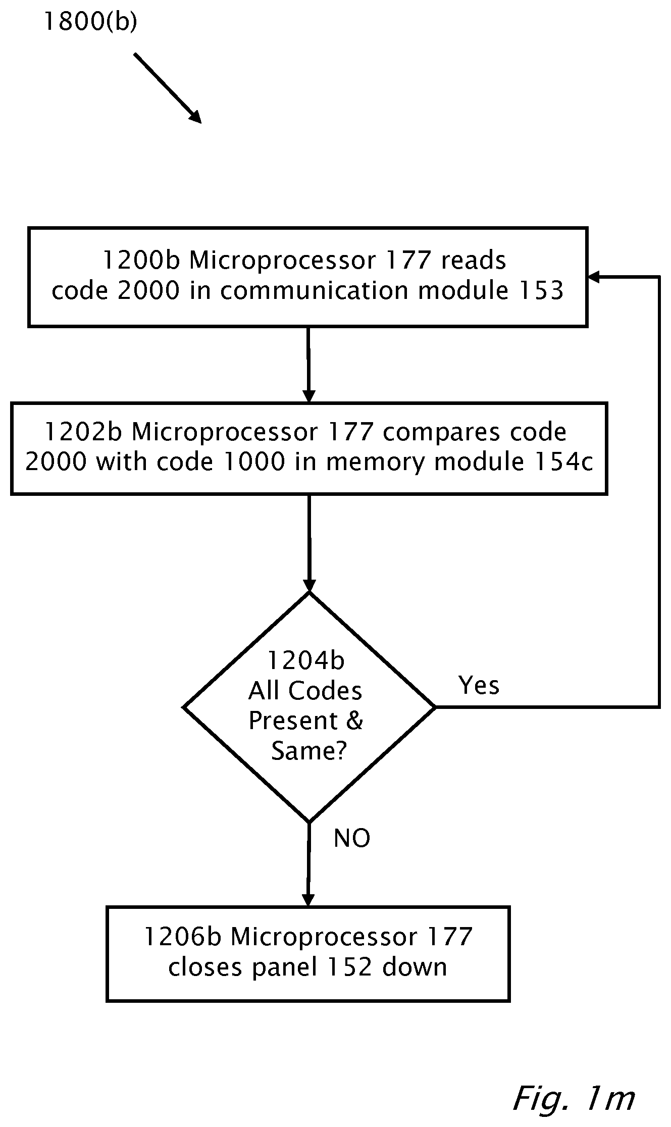
D00014

D00015
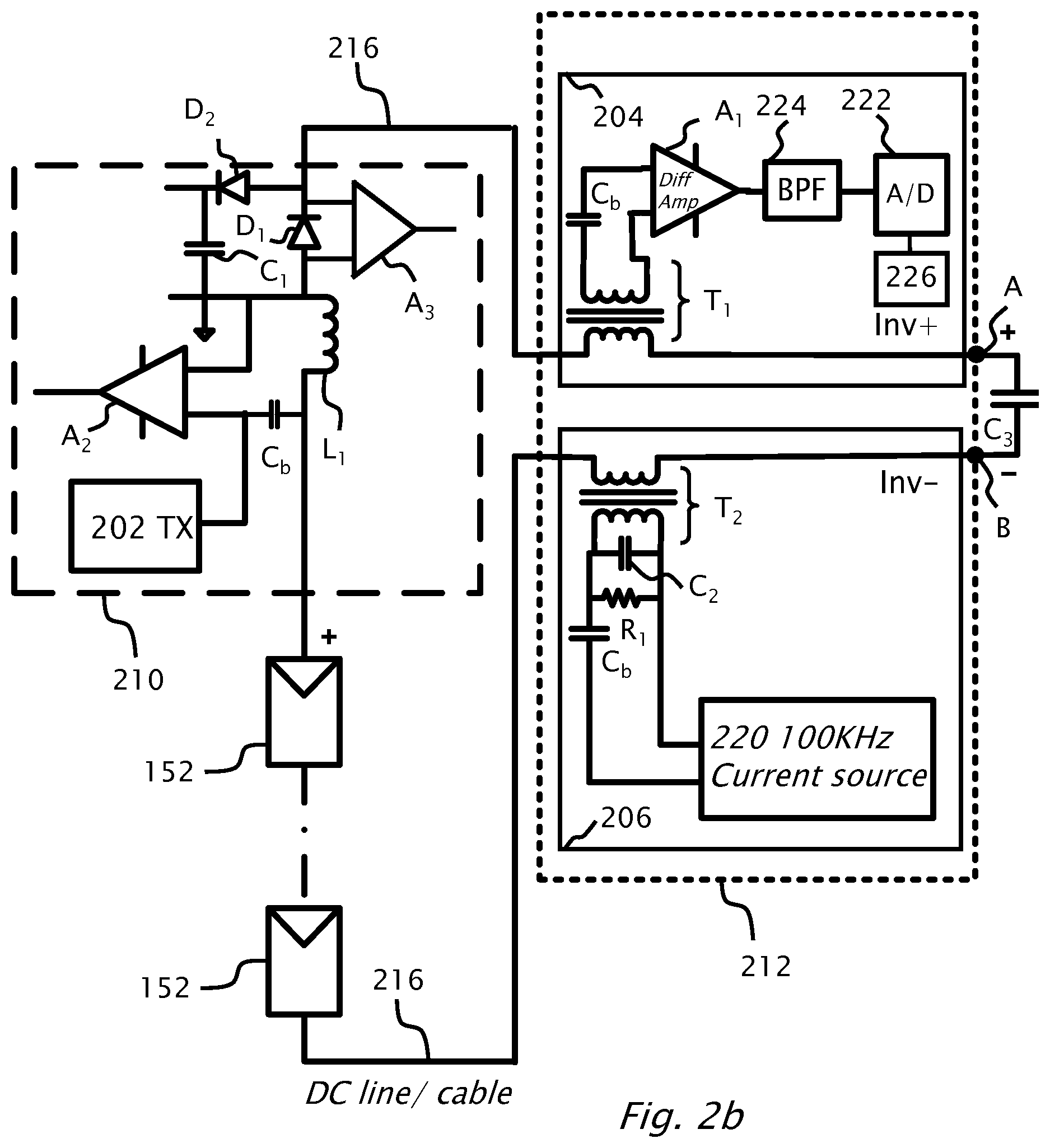
D00016
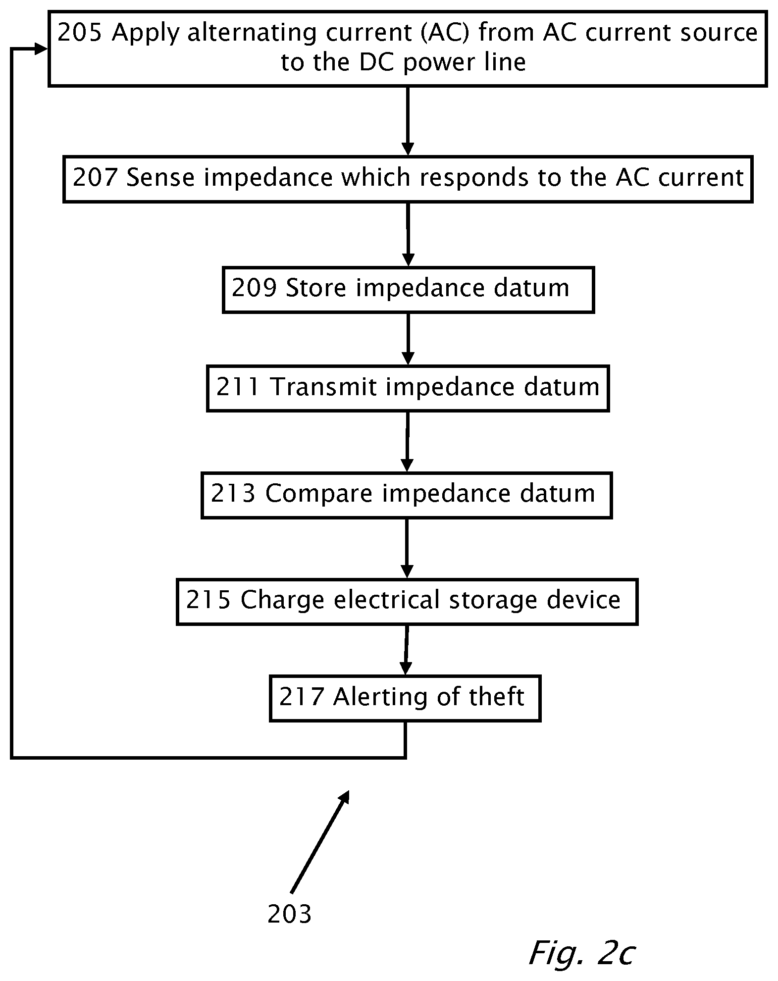
D00017

D00018
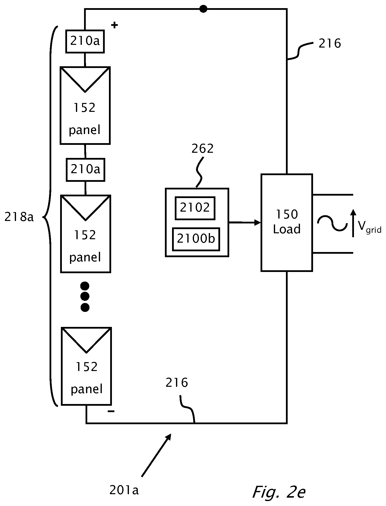
D00019
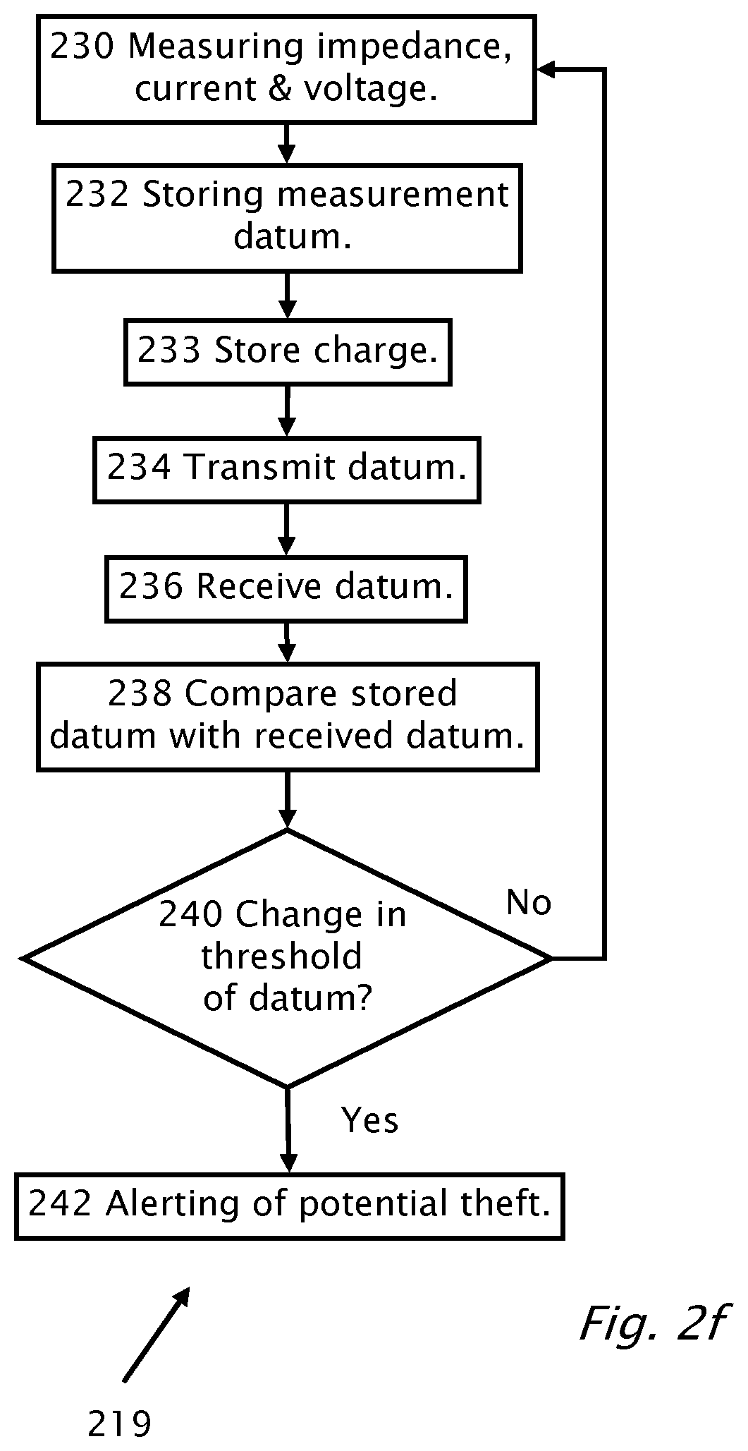
D00020

D00021
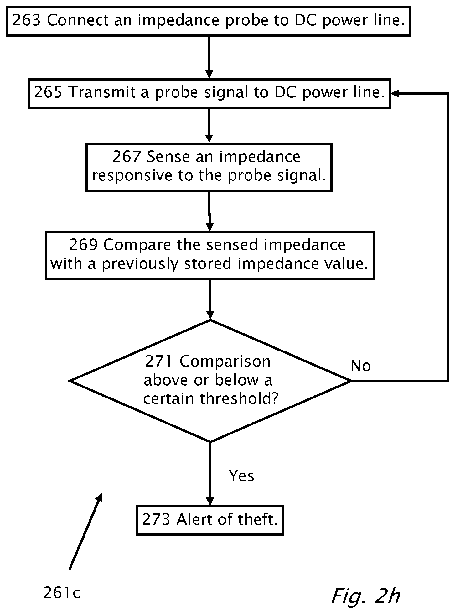
D00022

D00023
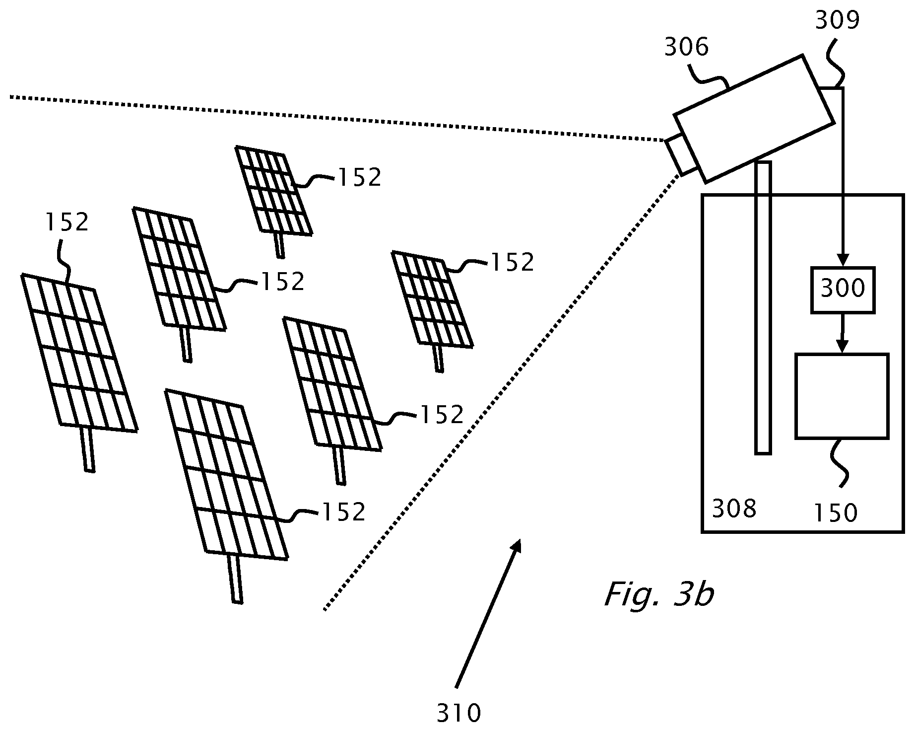
D00024

D00025

D00026

D00027

D00028

D00029
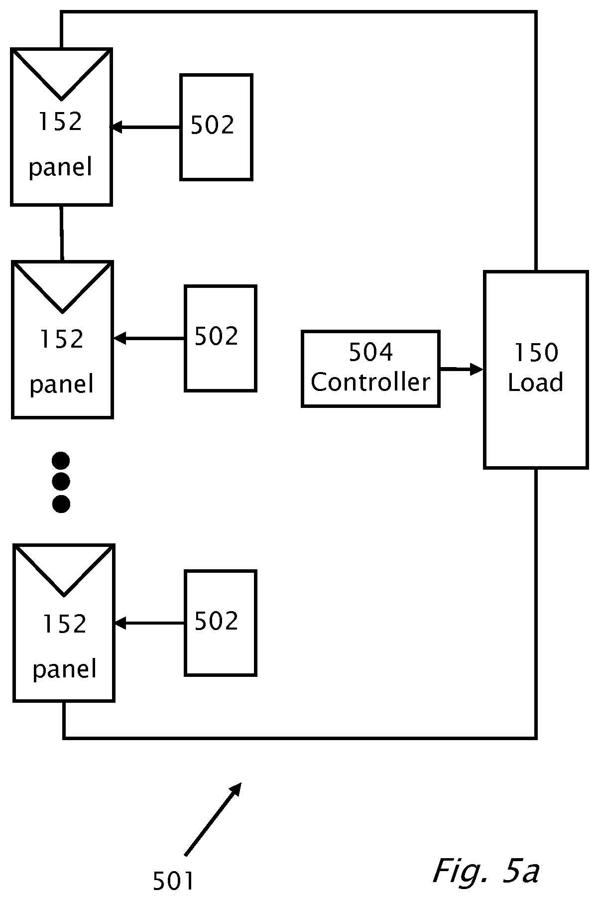
D00030

D00031
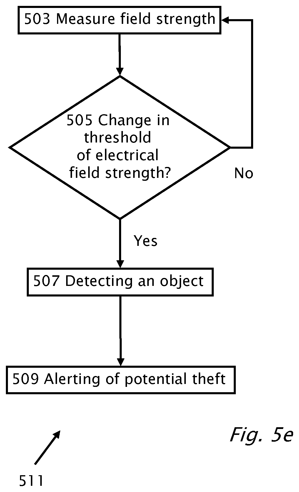
D00032
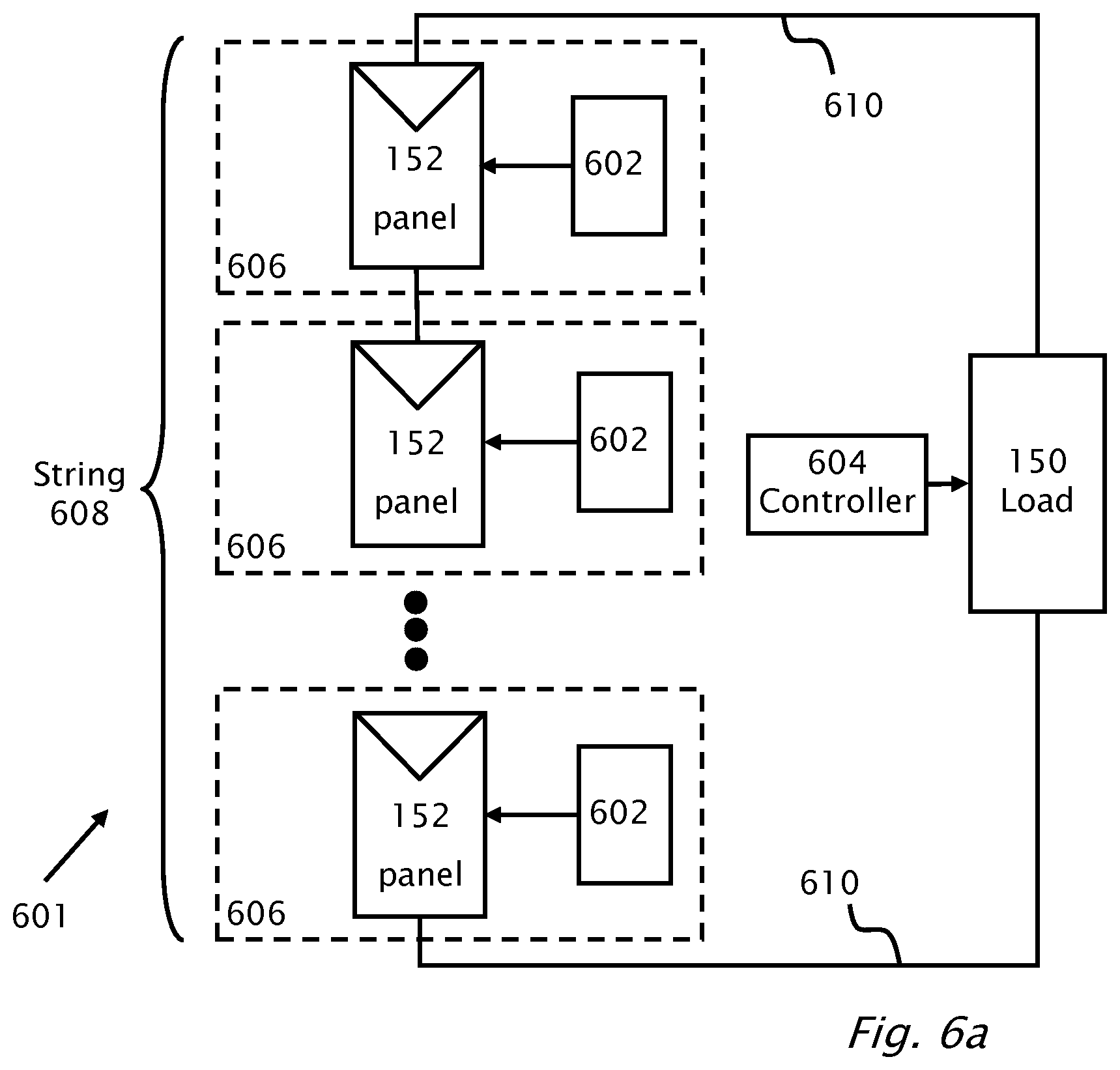
D00033

D00034
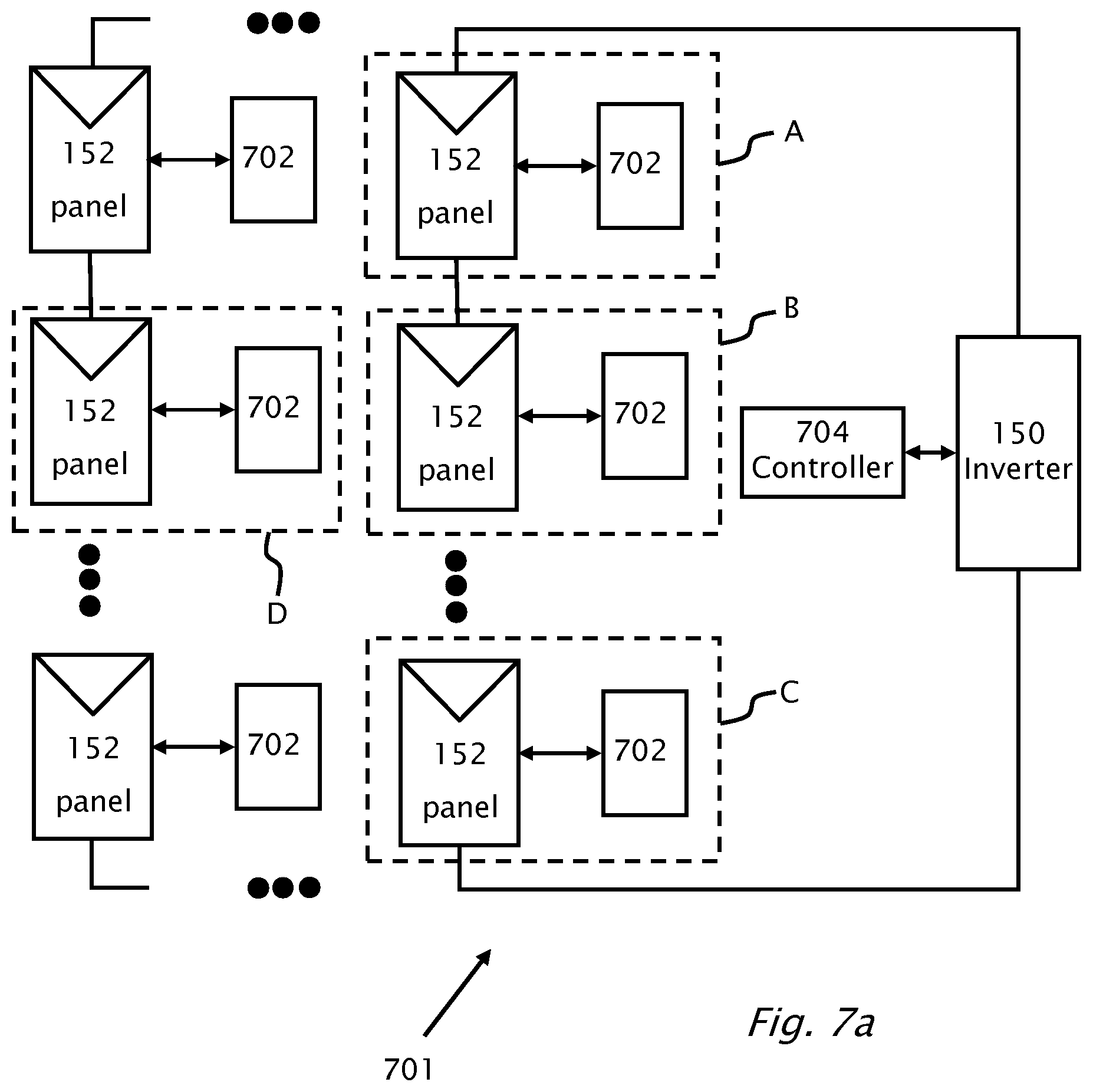
D00035
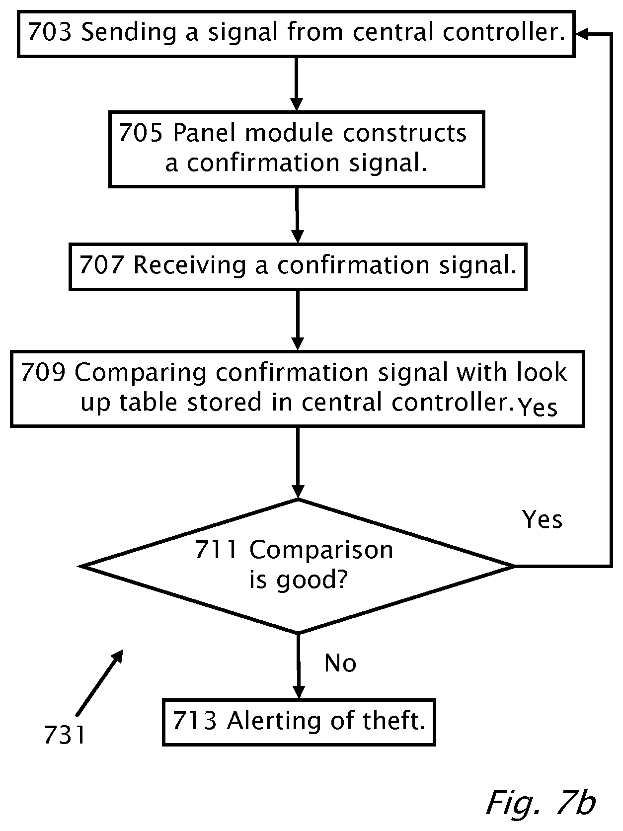
M00001

XML
uspto.report is an independent third-party trademark research tool that is not affiliated, endorsed, or sponsored by the United States Patent and Trademark Office (USPTO) or any other governmental organization. The information provided by uspto.report is based on publicly available data at the time of writing and is intended for informational purposes only.
While we strive to provide accurate and up-to-date information, we do not guarantee the accuracy, completeness, reliability, or suitability of the information displayed on this site. The use of this site is at your own risk. Any reliance you place on such information is therefore strictly at your own risk.
All official trademark data, including owner information, should be verified by visiting the official USPTO website at www.uspto.gov. This site is not intended to replace professional legal advice and should not be used as a substitute for consulting with a legal professional who is knowledgeable about trademark law.