Wi-Fi hotspot repeater
Hinman , et al. March 23, 2
U.S. patent number 10,958,332 [Application Number 14/848,202] was granted by the patent office on 2021-03-23 for wi-fi hotspot repeater. This patent grant is currently assigned to Mimosa Networks, Inc.. The grantee listed for this patent is Mimosa Networks, Inc.. Invention is credited to Jaime Fink, Brian L. Hinman, Mustafa Rangwala.


| United States Patent | 10,958,332 |
| Hinman , et al. | March 23, 2021 |
Wi-Fi hotspot repeater
Abstract
WiFi repeater devices described provided herein. An example device includes an enclosure that is configured to be mounted to a window that divides an outdoor area from an indoor area. The enclosure houses a 5 GHz WiFi client radio coupled with a high order MIMO (multiple input, multiple output) antenna, the high order MIMO antenna transmitting and receiving data from a 5 GHz access point located in the outdoor area, and a 2.4 GHz WiFi access point radio coupled with a MIMO (multiple input, multiple output) antenna, the MIMO antenna transmitting and receiving data from 2.4 GHz UEs located in the indoor area.
| Inventors: | Hinman; Brian L. (Los Gatos, CA), Rangwala; Mustafa (Sunnyvale, CA), Fink; Jaime (San Francisco, CA) | ||||||||||
|---|---|---|---|---|---|---|---|---|---|---|---|
| Applicant: |
|
||||||||||
| Assignee: | Mimosa Networks, Inc. (Santa
Clara, CA) |
||||||||||
| Family ID: | 1000005441951 | ||||||||||
| Appl. No.: | 14/848,202 | ||||||||||
| Filed: | September 8, 2015 |
Prior Publication Data
| Document Identifier | Publication Date | |
|---|---|---|
| US 20160149635 A1 | May 26, 2016 | |
Related U.S. Patent Documents
| Application Number | Filing Date | Patent Number | Issue Date | ||
|---|---|---|---|---|---|
| 62047640 | Sep 8, 2014 | ||||
| Current U.S. Class: | 1/1 |
| Current CPC Class: | H04B 7/026 (20130101); H04B 7/0413 (20130101); H04B 7/15507 (20130101) |
| Current International Class: | H04B 7/155 (20060101); H04B 7/04 (20170101); H04B 7/0413 (20170101); H04B 7/026 (20170101) |
References Cited [Referenced By]
U.S. Patent Documents
| 2735993 | February 1956 | Humphrey |
| 3182129 | May 1965 | Clark et al. |
| D227476 | June 1973 | Kennedy |
| 4188633 | February 1980 | Frazita |
| 4402566 | September 1983 | Powell et al. |
| D273111 | March 1984 | Hirata et al. |
| 4543579 | September 1985 | Teshirogi |
| 4562416 | December 1985 | Sedivec |
| 4626863 | December 1986 | Knop et al. |
| 4835538 | May 1989 | McKenna et al. |
| 4866451 | September 1989 | Chen |
| 4893288 | January 1990 | Maier et al. |
| 4903033 | February 1990 | Tsao et al. |
| 4986764 | January 1991 | Eaby et al. |
| 5015195 | May 1991 | Piriz |
| 5087920 | February 1992 | Tsurumaru et al. |
| 5226837 | July 1993 | Cinibulk et al. |
| 5231406 | July 1993 | Sreenivas |
| D346598 | May 1994 | McCay et al. |
| D355416 | February 1995 | McCay et al. |
| 5389941 | February 1995 | Yu |
| 5491833 | February 1996 | Hamabe |
| 5513380 | April 1996 | Ivanov et al. |
| 5539361 | July 1996 | Davidovitz |
| 5561434 | October 1996 | Yamazaki |
| D375501 | November 1996 | Lee et al. |
| 5580264 | December 1996 | Aoyama et al. |
| 5684495 | November 1997 | Dyott et al. |
| D389575 | January 1998 | Grasfield et al. |
| 5724666 | March 1998 | Dent |
| 5742911 | April 1998 | Dumbrill et al. |
| 5746611 | May 1998 | Brown et al. |
| 5764696 | June 1998 | Barnes et al. |
| 5797083 | August 1998 | Anderson |
| 5831582 | November 1998 | Muhlhauser et al. |
| 5966102 | October 1999 | Runyon |
| 5995063 | November 1999 | Somoza et al. |
| 6014372 | January 2000 | Kent et al. |
| 6067053 | May 2000 | Runyon et al. |
| 6137449 | October 2000 | Kildal |
| 6140962 | October 2000 | Groenenboom |
| 6176739 | January 2001 | Denlinger et al. |
| 6216266 | April 2001 | Eastman et al. |
| 6271802 | August 2001 | Clark et al. |
| 6304762 | October 2001 | Myers et al. |
| D455735 | April 2002 | Winslow |
| 6421538 | July 2002 | Byrne |
| 6716063 | April 2004 | Bryant et al. |
| 6754511 | June 2004 | Halford et al. |
| 6847653 | January 2005 | Smiroldo |
| D501848 | February 2005 | Uehara et al. |
| 6853336 | February 2005 | Asano et al. |
| 6864837 | March 2005 | Runyon et al. |
| 6877277 | April 2005 | Kussel et al. |
| 6962445 | November 2005 | Zimmel et al. |
| 7075492 | July 2006 | Chen et al. |
| D533899 | December 2006 | Ohashi et al. |
| 7173570 | February 2007 | Wensink et al. |
| 7187328 | March 2007 | Tanaka et al. |
| 7193562 | March 2007 | Shtrom et al. |
| 7212162 | May 2007 | Jung et al. |
| 7212163 | May 2007 | Huang et al. |
| 7245265 | July 2007 | Kienzle et al. |
| 7253783 | August 2007 | Chiang et al. |
| 7264494 | September 2007 | Kennedy et al. |
| 7281856 | October 2007 | Grzegorzewska et al. |
| 7292198 | November 2007 | Shtrom et al. |
| 7306485 | December 2007 | Masuzaki |
| 7316583 | January 2008 | Mistarz |
| 7324057 | January 2008 | Argaman et al. |
| D566698 | April 2008 | Choi et al. |
| 7362236 | April 2008 | Hoiness |
| 7369095 | May 2008 | Hirtzlin et al. |
| 7380984 | June 2008 | Wuester |
| 7431602 | October 2008 | Corona |
| 7436373 | October 2008 | Lopes et al. |
| 7498896 | March 2009 | Shi |
| 7498996 | March 2009 | Shtrom et al. |
| 7507105 | March 2009 | Peters et al. |
| 7522095 | April 2009 | Wasiewicz et al. |
| 7542717 | June 2009 | Green, Sr. et al. |
| 7581976 | September 2009 | Liepold et al. |
| 7586891 | September 2009 | Masciulli |
| 7616959 | November 2009 | Spenik et al. |
| 7646343 | January 2010 | Shtrom et al. |
| 7675473 | March 2010 | Kienzle et al. |
| 7675474 | March 2010 | Shtrom et al. |
| 7726997 | June 2010 | Kennedy et al. |
| 7778226 | August 2010 | Rayzman et al. |
| 7857523 | December 2010 | Masuzaki |
| 7929914 | April 2011 | Tegreene |
| RE42522 | July 2011 | Zimmel et al. |
| 8009646 | August 2011 | Lastinger et al. |
| 8069465 | November 2011 | Bartholomay et al. |
| 8111678 | February 2012 | Lastinger et al. |
| 8254844 | August 2012 | Kuffner et al. |
| 8270383 | September 2012 | Lastinger et al. |
| 8275265 | September 2012 | Kobyakov et al. |
| 8325695 | December 2012 | Lastinger et al. |
| D674787 | January 2013 | Tsuda et al. |
| 8345651 | January 2013 | Lastinger et al. |
| 8385305 | February 2013 | Negus et al. |
| 8425260 | April 2013 | Seefried et al. |
| 8482478 | July 2013 | Hartenstein |
| 8515434 | August 2013 | Narendran et al. |
| 8515495 | August 2013 | Shang et al. |
| D694740 | December 2013 | Apostolakis |
| 8777660 | July 2014 | Chiarelli et al. |
| 8792759 | July 2014 | Benton et al. |
| 8827729 | September 2014 | Gunreben et al. |
| 8836601 | September 2014 | Sanford et al. |
| 8848389 | September 2014 | Kawamura et al. |
| 8870069 | October 2014 | Bellows |
| 8935122 | January 2015 | Stisser |
| 9001689 | April 2015 | Hinman et al. |
| 9019874 | April 2015 | Choudhury et al. |
| 9077071 | July 2015 | Shtrom et al. |
| 9107134 | August 2015 | Belser et al. |
| 9130305 | September 2015 | Ramos et al. |
| 9161387 | October 2015 | Fink et al. |
| 9179336 | November 2015 | Fink et al. |
| 9191081 | November 2015 | Hinman et al. |
| D752566 | March 2016 | Hinman et al. |
| 9295103 | March 2016 | Fink et al. |
| 9362629 | June 2016 | Hinman et al. |
| 9391375 | July 2016 | Bales et al. |
| 9407012 | August 2016 | Shtrom et al. |
| 9431702 | August 2016 | Hartenstein |
| 9504049 | November 2016 | Hinman et al. |
| 9531114 | December 2016 | Ramos et al. |
| 9537204 | January 2017 | Cheng et al. |
| 9577340 | February 2017 | Fakharzadeh et al. |
| 9693388 | June 2017 | Fink et al. |
| 9780892 | October 2017 | Hinman et al. |
| 9843940 | December 2017 | Hinman et al. |
| 9871302 | January 2018 | Hinman et al. |
| 9888485 | February 2018 | Hinman et al. |
| 9930592 | March 2018 | Hinman |
| 9949147 | April 2018 | Hinman et al. |
| 9986565 | May 2018 | Fink et al. |
| 9998246 | June 2018 | Hinman et al. |
| 10028154 | July 2018 | Elson |
| 10090943 | October 2018 | Hinman et al. |
| 10096933 | October 2018 | Ramos et al. |
| 10117114 | October 2018 | Hinman et al. |
| 10186786 | January 2019 | Hinman et al. |
| 10200925 | February 2019 | Hinman |
| 10257722 | April 2019 | Hinman et al. |
| 10425944 | September 2019 | Fink et al. |
| 10447417 | October 2019 | Hinman et al. |
| 10511074 | December 2019 | Eberhardt et al. |
| 10595253 | March 2020 | Hinman |
| 10616903 | April 2020 | Hinman et al. |
| 10714805 | July 2020 | Eberhardt et al. |
| 10742275 | August 2020 | Hinman |
| 10785608 | September 2020 | Fink et al. |
| 10790613 | September 2020 | Ramos et al. |
| 10812994 | October 2020 | Hinman et al. |
| 10863507 | December 2020 | Fink et al. |
| 2001/0033600 | October 2001 | Yang et al. |
| 2002/0102948 | August 2002 | Stanwood et al. |
| 2002/0159434 | October 2002 | Gosior et al. |
| 2003/0013452 | January 2003 | Hunt et al. |
| 2003/0027577 | February 2003 | Brown et al. |
| 2003/0169763 | September 2003 | Choi et al. |
| 2003/0222831 | December 2003 | Dunlap |
| 2003/0224741 | December 2003 | Sugar et al. |
| 2004/0002357 | January 2004 | Benveniste |
| 2004/0029549 | February 2004 | Fikart |
| 2004/0110469 | June 2004 | Judd |
| 2004/0120277 | June 2004 | Holur et al. |
| 2004/0155819 | August 2004 | Martin et al. |
| 2004/0196812 | October 2004 | Barber |
| 2004/0196813 | October 2004 | Ofek et al. |
| 2004/0240376 | December 2004 | Wang et al. |
| 2004/0242274 | December 2004 | Corbett et al. |
| 2005/0012665 | January 2005 | Runyon et al. |
| 2005/0032479 | February 2005 | Miller et al. |
| 2005/0058111 | March 2005 | Hung et al. |
| 2005/0124294 | June 2005 | Wentink |
| 2005/0143014 | June 2005 | Li et al. |
| 2005/0152323 | July 2005 | Bonnassieux |
| 2005/0195758 | September 2005 | Chitrapu |
| 2005/0227625 | October 2005 | Diener |
| 2005/0254442 | November 2005 | Proctor, Jr. |
| 2005/0271056 | December 2005 | Kaneko |
| 2005/0275527 | December 2005 | Kates |
| 2006/0025072 | February 2006 | Pan |
| 2006/0072518 | April 2006 | Pan et al. |
| 2006/0098592 | May 2006 | Proctor, Jr. |
| 2006/0099940 | May 2006 | Pfleging et al. |
| 2006/0132359 | June 2006 | Chang et al. |
| 2006/0132602 | June 2006 | Muto et al. |
| 2006/0172578 | August 2006 | Parsons |
| 2006/0187952 | August 2006 | Kappes et al. |
| 2006/0211430 | September 2006 | Persico |
| 2006/0276073 | December 2006 | McMurray et al. |
| 2007/0001910 | January 2007 | Yamanaka et al. |
| 2007/0019664 | January 2007 | Benveniste |
| 2007/0035463 | February 2007 | Hirabayashi |
| 2007/0060158 | March 2007 | Medepalli et al. |
| 2007/0132643 | June 2007 | Durham et al. |
| 2007/0173199 | July 2007 | Sinha |
| 2007/0173260 | July 2007 | Love et al. |
| 2007/0202809 | August 2007 | Lastinger et al. |
| 2007/0210974 | September 2007 | Chiang |
| 2007/0223701 | September 2007 | Emeott et al. |
| 2007/0238482 | October 2007 | Rayzman et al. |
| 2007/0255797 | November 2007 | Dunn et al. |
| 2007/0268848 | November 2007 | Khandekar et al. |
| 2008/0109051 | May 2008 | Splinter et al. |
| 2008/0112380 | May 2008 | Fischer |
| 2008/0192707 | August 2008 | Xhafa et al. |
| 2008/0218418 | September 2008 | Gillette |
| 2008/0231541 | September 2008 | Teshirogi et al. |
| 2008/0242342 | October 2008 | Rofougaran |
| 2009/0046673 | February 2009 | Kaidar |
| 2009/0051597 | February 2009 | Wen et al. |
| 2009/0052362 | February 2009 | Meier et al. |
| 2009/0059794 | March 2009 | Frei |
| 2009/0075606 | March 2009 | Shtrom et al. |
| 2009/0096699 | April 2009 | Chiu et al. |
| 2009/0232026 | September 2009 | Lu |
| 2009/0233475 | September 2009 | Mildon et al. |
| 2009/0291690 | November 2009 | Guvenc et al. |
| 2009/0315792 | December 2009 | Miyashita et al. |
| 2010/0029282 | February 2010 | Stamoulis et al. |
| 2010/0034191 | February 2010 | Schulz |
| 2010/0039340 | February 2010 | Brown |
| 2010/0046650 | February 2010 | Jongren et al. |
| 2010/0067505 | March 2010 | Fein et al. |
| 2010/0085950 | April 2010 | Sekiya et al. |
| 2010/0091818 | April 2010 | Sen et al. |
| 2010/0103065 | April 2010 | Shtrom et al. |
| 2010/0103066 | April 2010 | Shtrom et al. |
| 2010/0119002 | May 2010 | Hartenstein |
| 2010/0136978 | June 2010 | Cho et al. |
| 2010/0151877 | June 2010 | Lee et al. |
| 2010/0167719 | July 2010 | Sun |
| 2010/0171665 | July 2010 | Nogami |
| 2010/0171675 | July 2010 | Borja et al. |
| 2010/0177660 | July 2010 | Essinger |
| 2010/0189005 | July 2010 | Bertani et al. |
| 2010/0202613 | August 2010 | Ray et al. |
| 2010/0210147 | August 2010 | Hauser |
| 2010/0216412 | August 2010 | Rofougaran |
| 2010/0225529 | September 2010 | Landreth et al. |
| 2010/0238083 | September 2010 | Malasani |
| 2010/0304680 | December 2010 | Kuffner et al. |
| 2010/0311321 | December 2010 | Morin |
| 2010/0315307 | December 2010 | Syed et al. |
| 2010/0329919 | December 2010 | Fischer et al. |
| 2011/0006956 | January 2011 | McCown |
| 2011/0028097 | February 2011 | Memik et al. |
| 2011/0032159 | February 2011 | Wu et al. |
| 2011/0044186 | February 2011 | Jung et al. |
| 2011/0090129 | April 2011 | Weily et al. |
| 2011/0103309 | May 2011 | Wang et al. |
| 2011/0111715 | May 2011 | Buer et al. |
| 2011/0112717 | May 2011 | Resner |
| 2011/0133996 | June 2011 | Alapuranen |
| 2011/0170424 | July 2011 | Safavi |
| 2011/0172916 | July 2011 | Pakzad et al. |
| 2011/0182260 | July 2011 | Sivakumar et al. |
| 2011/0182277 | July 2011 | Shapira |
| 2011/0194644 | August 2011 | Liu et al. |
| 2011/0206012 | August 2011 | Youn et al. |
| 2011/0241969 | October 2011 | Zhang et al. |
| 2011/0243291 | October 2011 | McAllister et al. |
| 2011/0256874 | October 2011 | Hayama et al. |
| 2011/0291914 | December 2011 | Lewry et al. |
| 2012/0008542 | January 2012 | Koleszar et al. |
| 2012/0040700 | February 2012 | Gomes et al. |
| 2012/0057533 | March 2012 | Junell et al. |
| 2012/0093091 | April 2012 | Kang et al. |
| 2012/0115487 | May 2012 | Josso |
| 2012/0134280 | May 2012 | Rotvold et al. |
| 2012/0140651 | June 2012 | Nicoara et al. |
| 2012/0200449 | August 2012 | Bielas |
| 2012/0238201 | September 2012 | Du et al. |
| 2012/0263145 | October 2012 | Marinier et al. |
| 2012/0282868 | November 2012 | Hahn |
| 2012/0299789 | November 2012 | Orban et al. |
| 2012/0314634 | December 2012 | Sekhar |
| 2013/0003645 | January 2013 | Shapira |
| 2013/0005350 | January 2013 | Campos et al. |
| 2013/0023216 | January 2013 | Moscibroda et al. |
| 2013/0044028 | February 2013 | Lea et al. |
| 2013/0064161 | March 2013 | Hedayat et al. |
| 2013/0082899 | April 2013 | Gomi |
| 2013/0095747 | April 2013 | Moshfeghi |
| 2013/0128858 | May 2013 | Zou et al. |
| 2013/0176902 | July 2013 | Wentink et al. |
| 2013/0182652 | July 2013 | Tong et al. |
| 2013/0195081 | August 2013 | Merlin et al. |
| 2013/0210457 | August 2013 | Kummetz |
| 2013/0223398 | August 2013 | Li |
| 2013/0234898 | September 2013 | Leung et al. |
| 2013/0271319 | October 2013 | Trerise |
| 2013/0286950 | October 2013 | Pu |
| 2013/0286959 | October 2013 | Lou et al. |
| 2013/0288735 | October 2013 | Guo |
| 2013/0301438 | November 2013 | Li et al. |
| 2013/0322276 | December 2013 | Pelletier et al. |
| 2013/0322413 | December 2013 | Pelletier et al. |
| 2014/0024328 | January 2014 | Balbien et al. |
| 2014/0051357 | February 2014 | Steer et al. |
| 2014/0098748 | April 2014 | Chan et al. |
| 2014/0113676 | April 2014 | Hamalainen |
| 2014/0145890 | May 2014 | Ramberg et al. |
| 2014/0154895 | June 2014 | Poulsen et al. |
| 2014/0185494 | July 2014 | Yang et al. |
| 2014/0191918 | July 2014 | Cheng et al. |
| 2014/0198867 | July 2014 | Sturkovich et al. |
| 2014/0206322 | July 2014 | Dimou et al. |
| 2014/0225788 | August 2014 | Schulz et al. |
| 2014/0233613 | August 2014 | Fink et al. |
| 2014/0235244 | August 2014 | Hinman |
| 2014/0253378 | September 2014 | Hinman |
| 2014/0253402 | September 2014 | Hinman et al. |
| 2014/0254700 | September 2014 | Hinman et al. |
| 2014/0256166 | September 2014 | Ramos et al. |
| 2014/0320306 | October 2014 | Winter |
| 2014/0320377 | October 2014 | Cheng et al. |
| 2014/0328238 | November 2014 | Seok et al. |
| 2014/0341013 | November 2014 | Kumar |
| 2014/0355578 | December 2014 | Fink et al. |
| 2014/0355584 | December 2014 | Fink et al. |
| 2015/0002335 | January 2015 | Hinman et al. |
| 2015/0002354 | January 2015 | Knowles |
| 2015/0015435 | January 2015 | Shen et al. |
| 2015/0116177 | April 2015 | Powell et al. |
| 2015/0156642 | June 2015 | Sobczak et al. |
| 2015/0215952 | July 2015 | Hinman et al. |
| 2015/0256213 | September 2015 | Jan et al. |
| 2015/0256275 | September 2015 | Hinman et al. |
| 2015/0263816 | September 2015 | Hinman et al. |
| 2015/0319584 | November 2015 | Fink et al. |
| 2015/0321017 | November 2015 | Perryman et al. |
| 2015/0325945 | November 2015 | Ramos et al. |
| 2015/0327272 | November 2015 | Fink et al. |
| 2015/0365866 | December 2015 | Hinman et al. |
| 2016/0119018 | April 2016 | Lindgren |
| 2016/0149634 | May 2016 | Kalkunte et al. |
| 2016/0211583 | July 2016 | Lee et al. |
| 2016/0338076 | November 2016 | Hinman et al. |
| 2016/0365666 | December 2016 | Ramos et al. |
| 2016/0366601 | December 2016 | Hinman et al. |
| 2017/0048647 | February 2017 | Jung et al. |
| 2017/0201028 | July 2017 | Eberhardt et al. |
| 2017/0238151 | August 2017 | Fink et al. |
| 2017/0294975 | October 2017 | Hinman et al. |
| 2017/0353245 | December 2017 | Vardarajan |
| 2018/0034166 | February 2018 | Hinman |
| 2018/0035317 | February 2018 | Hinman et al. |
| 2018/0083365 | March 2018 | Hinman et al. |
| 2018/0084563 | March 2018 | Hinman et al. |
| 2018/0160353 | June 2018 | Hinman |
| 2018/0167105 | June 2018 | Vannucci et al. |
| 2018/0192305 | July 2018 | Hinman et al. |
| 2018/0199345 | July 2018 | Fink et al. |
| 2018/0241491 | August 2018 | Hinman et al. |
| 2019/0006789 | January 2019 | Ramos et al. |
| 2019/0182686 | June 2019 | Hinman et al. |
| 2019/0214699 | July 2019 | Eberhardt et al. |
| 2019/0215745 | July 2019 | Hinman |
| 2019/0273326 | September 2019 | Sanford et al. |
| 2020/0015231 | January 2020 | Fink et al. |
| 2020/0036465 | January 2020 | Hinman et al. |
| 2020/0067164 | February 2020 | Eberhardt et al. |
| 2020/0083614 | March 2020 | Sanford et al. |
| 104335654 | Feb 2015 | CN | |||
| 303453662 | Nov 2015 | CN | |||
| 105191204 | Dec 2015 | CN | |||
| 105191204 | May 2019 | CN | |||
| 1384285 | Jun 2007 | EP | |||
| 002640177 | Feb 2015 | EP | |||
| 3491697 | Jun 2019 | EP | |||
| WO2014137370 | Sep 2014 | WO | |||
| WO2014138292 | Sep 2014 | WO | |||
| WO2014193394 | Dec 2014 | WO | |||
| WO2015112627 | Jul 2015 | WO | |||
| WO2017123558 | Jul 2017 | WO | |||
| WO2018022526 | Feb 2018 | WO | |||
| WO2019136257 | Jul 2019 | WO | |||
| WO2019168800 | Sep 2019 | WO | |||
Other References
|
Weisstein, Eric "Electric Polarization", Retrieved from the Internet [retrieved Mar. 23, 2007] available at <http://scienceworld.wolfram.com/physics/ElectricPolarization.html>- , 1 page. cited by applicant . Liu, Lingjia et al., "Downlink MIMO in LTE-Advanced: SU-MIMO vs. MU-MIMO," IEEE Communications Magazine, Feb. 2012, pp. 140-147. cited by applicant . International Search Report and "Written Opinion of the International Searching Authority," Patent Cooperation Treaty Application No. PCT/US2017/012884, dated Apr. 6, 2017, 9 pages. cited by applicant . International Search Report and Written Opinion of the International Search Authority dated Nov. 26, 2013 in Patent Cooperation Treaty Application No. PCT/US2013/047406, filed Jun. 24, 2013. cited by applicant . International Search Report and Written Opinion of the International Search Authority dated Aug. 9, 2013 in Patent Cooperation Treaty Application No. PCT/US2013/043436, filed May 30, 2013. cited by applicant . International Search Report and Written Opinion of the International Search Authority dated Jul. 1, 2014 in Patent Cooperation Treaty Application No. PCT/US2014/020880, filed Mar. 5, 2014. cited by applicant . International Search Report and Written Opinion of the International Search Authority dated Jun. 29, 2015 in Patent Cooperation Treaty Application No. PCT/US2015/012285, filed Jan. 21, 2015. cited by applicant . Hinman et al., U.S. Appl. No. 61/774,632, filed Mar. 7, 2013. cited by applicant . First Official Notification dated Jun. 15, 2015 in Chinese Design Patent Application 201530058063.8, filed Mar. 11, 2015. cited by applicant . Notice of Allowance dated Sep. 8, 2015 in Chinese Design Patent Application 201530058063.8, filed Mar. 11, 2015. cited by applicant . Final Office Action, dated Sep. 21, 2017, U.S. Appl. No. 15/246,118, filed Aug. 24, 2016. cited by applicant . Notice of Allowance, dated Sep. 29, 2017, U.S. Appl. No. 15/139,225, filed Apr. 26, 2016. cited by applicant . Notice of Allowance, dated Oct. 10, 2017, U.S. Appl. No. 15/224,412, filed Jul. 29, 2016. cited by applicant . Final Office Ation, dated Oct. 24, 2017, U.S. Appl. No. 14/316,537, filed Jun. 26, 2014. cited by applicant . Final Office Action, dated Nov. 14, 2017, U.S. Appl. No. 14/198,473, filed Mar. 5, 2014. cited by applicant . Non-Final Office Action, dated Nov. 16, 2017, U.S. Appl. No. 15/625,984, filed Jun. 16, 2017. cited by applicant . "Office Action," Chinese Patent Application No. 201580000078.6, dated Nov. 3, 2017, 5 pages [10 pages including translation]. cited by applicant . "International Search Report" and "Written Opinion of the International Searching Authority," Patent Cooperation Treaty Application No. PCT/US2017/043560, dated Nov. 16, 2017, 11 pages. cited by applicant . "Office Action," Chinese Patent Application No. 201580000078.6, dated Oct. 31, 2018, 3 pages. cited by applicant . "International Search Report" and "Written Opinion of the International Search Authority," dated May 23, 2019 in Patent Cooperation Treaty Application No. PCT/US2019/019462, filed Feb. 25, 2019, 8 pages. cited by applicant . Teshirogi, Tasuku et al., "Wideband Circularly Polarized Array Antenna with Sequential Rotations and Phase Shift of Elements," Proceedings of the International Symposium on Antennas and Propagation, 1985, pp. 117-120. cited by applicant . "Office Action," Chinese Patent Application No. 201580000078.6, dated Jul. 30, 2018, 5 pages [11 pages including translation]. cited by applicant . "Office Action," Chinese Patent Application No. 201580000078.6, dated Oct. 31, 2018, 3 pages [6 pages including translation]. cited by applicant . "Notice of Allowance," Chinese Patent Application No. 201580000078.6, dated Feb. 11, 2019, 2 pages. cited by applicant . "International Search Report" and "Written Opinion of the International Search Authority," dated Mar. 22, 2019 in Patent Cooperation Treaty Application No. PCT/US2019/012358, filed Jan. 4, 2019, 9 pages. cited by applicant . FCC Regulations, 47 CFR .sctn. 15.407, 63 FR 40836, Jul. 31, 1998, as amended at 69 FR 2687, Jan. 20, 2004; 69 FR 54036, Sep. 7, 2004; pp. 843-846. cited by applicant . "Sector Antennas," Radiowaves.com, [online], [retrieved Oct. 10, 2019], Retrieved from the Internet: <URL:https://www.radiowaves.com/en/products/sector-antennas>, 4 pages. cited by applicant . KP Performance Antennas Search Results for Antennas, Sector, Single, [online], KPPerformance.com [retrieved Oct. 10, 2019], Retrieved from the Internet: <URL:https://www.kpperformance.com/search?Category=Antennas&- Rfpsan99design=Sector&Rfpsan99option=Single&view_type=grid>, 6 pages. cited by applicant . "Partial Supplemental European Search Report," European Patent Application No. 17835073.2, dated Feb. 13, 2020, 17 pages. cited by applicant . "Wireless Access Point," Wikipedia.org, Jan. 6, 2020 [retrieved on Feb. 3, 2020], Retrieved from the Internet: <https://en.wikipedia.org/wiki/Wireless_access_point>, 5 pages. cited by applicant . "Extended European Search Report", European Patent Application No. 17835073.2, dated Jun. 30, 2020, 15 pages. cited by applicant . Haupt, R.T., "Antenna Arrays: A Computational Approach", Chapter 5: Non-Planar Arrays; Wiley-IEEE Press (2010), pp. 287-338. cited by applicant . Dowla, Farid et al., "RF and Wireless Technologies: Know It All", Netherlands, Elsevier Science, 2008, p. 314. cited by applicant. |
Primary Examiner: Harper; Kevin C.
Assistant Examiner: Rose; Derrick V
Attorney, Agent or Firm: Carr & Ferrell LLP
Parent Case Text
CROSS REFERENCE TO RELATED APPLICATIONS
This application claims the priority benefit of U.S. Provisional Patent Application Ser. No. 62/047,640, filed on Sep. 8, 2014, titled "Wi-Fi Hotspot Repeater", which is hereby incorporated by reference herein in its entirety, including all references cited therein.
Claims
What is claimed is:
1. A repeater device, comprising: an enclosure that is configured to be mounted to a window that divides an outdoor area from an indoor area, the enclosure comprising an indoor oriented surface and an outdoor oriented surface, the enclosure having disposed therein: a 5 GHz WiFi client radio coupled with a high order MIMO (multiple input, multiple output) antenna, the high order MIMO antenna being at least 4.times.4, the high order MIMO antenna transmitting and receiving data from a 5 GHz access point located in the outdoor area, wherein the high order MIMO antenna is oriented towards an outdoor facing surface of the enclosure and transmitting the data through the outdoor oriented surface of the enclosure and receives data from the 5 GHz access point on a first channel, the 5 GHz WiFi client radio communicating with 5 GHz (User Equipments) UEs in the indoor area; a 2.4 GHz WiFi access point radio coupled with a 2.times.2 MIMO (multiple input, multiple output) antenna, the 2.times.2 MIMO antenna transmitting and receiving data from 2.4 GHz UEs located in the indoor area, wherein the 2.times.2 MIMO antenna is oriented towards an indoor facing surface of the enclosure and transmitting the data through the indoor oriented surface of the enclosure; a microprocessor controlling both the 5 GHz WiFi client radio and the 2.4 GHz WiFi access point radio, the microprocessor configured to: receive a channel change signal transmitted to the 5 GHz WiFi client radio by the 5 GHz outdoor access point; request a change of the first channel used by the 5 GHz WiFi client radio and the access point radio to a second channel; transmit a signal change signal to the 5 GHz UEs informing the 5 GHz UEs of the change to the second channel; convert 5 GHz data received by the 5 GHz WiFi client radio into 2.4 GHz data; convert 2.4 GHz data received by the 2.4 GHz WiFi access point radio into 5 GHz data, the microprocessor disposed within the enclosure and coupled with both the 5 GHz WiFi client radio and the 2.4 GHz WiFi access point radio; and beam form a beam of the high order MIMO antenna to maximize a signal strength of an output directed towards the 5 GHz access point in a direction that is parallel and relative to a beam-forming plane that is normal to the window; and a wireless interface for coupling with a wireless router, the wireless router transmitting converted data to the 5 GHz UEs and the 2.4 GHz UEs located in the indoor area, the wireless interface being disposed within a wall adapter that can electrically couple with an electrical outlet.
2. A repeater device, comprising: an enclosure that is configured to be mounted to a window that divides an outdoor area from an indoor area, the enclosure housing: a first radio operating on a first frequency, the first radio coupled with a first antenna which is at least a 4.times.4, high-order Multiple Input Multiple Output (MIMO) antenna, the first antenna transmitting and receiving data from an outdoor access point located in the outdoor area, wherein the first antenna is oriented towards an outdoor facing surface of the enclosure and the first radio receives the data on a first channel from the outdoor access point and communicates with UEs (User Equipments) in the indoor area; an access point radio coupled with a second antenna that is a 2.times.2 MIMO antenna, the second antenna transmitting to and receiving data from UEs located in the indoor area using a second frequency, wherein the second antenna is oriented towards an indoor facing surface of the enclosure; and a microprocessor that is configured to convert data having the first frequency received by the first radio into data having the second frequency and convert data having the second frequency received by the access point radio into data having the first frequency, the microprocessor disposed within the enclosure and coupled with both the first radio and the access point radio, the microprocessor controlling both the first radio and the access point radio, the microprocessor being further configured to: receive a channel change signal from the first radio transmitted by the outdoor access point; request a change of the first channel used by the first radio and the access point radio to a second channel; transmit a signal change signal to the UEs informing the UEs of the change to the second channel; and provide beam forming a beam of the first antenna to maximize a signal strength of an output of the first radio directed towards the outdoor access point in a direction that is parallel and relative to a beam-forming plane that is normal to the window.
3. The repeater device according to claim 2, wherein the first frequency and the second frequency are different from one another.
4. The repeater device according to claim 3, wherein the first frequency is 5 GHz and the second frequency is 2.4 GHz.
5. The repeater device according to claim 2, further comprising a data cable coupled to the repeater device and a wall adapter.
6. The repeater device according to claim 2, wherein the first antenna is disposed proximate the window and the second antenna is disposed away from the window.
7. The repeater device according to claim 2, wherein the first antenna uses beam-forming which allows a maximum gain for radiation produced by the first antenna to be steered in a direction that is advantageous for communicating with the outdoor access point.
8. The repeater device according to claim 2, wherein the microprocessor is configured to implement firewall policies to secure a private network created by the repeater device for the UEs located in the indoor area.
9. The repeater device according to claim 2, further comprising a wall adapter that comprises a power over Ethernet adapter that electrically and communicatively couples a wireless interface with the microprocessor and first radio using a power over Ethernet connection.
10. A repeater device, comprising: an enclosure that is configured to be mounted to a window that divides an outdoor area from an indoor area, the enclosure housing: a first radio operating on a first frequency, the first radio coupled with a first antenna which is a 4.times.4, high-order MIMO (multiple input, multiple output) antenna, the first antenna receiving data from an outdoor access point located in the outdoor area, wherein the first antenna is oriented towards an outdoor facing surface of the enclosure that is against the window, the first radio receiving the data on a first channel from the outdoor access point, the first radio communicating with UEs (User Equipments) in the indoor area; a microprocessor that converts the data from the first frequency to a second frequency and data from the second frequency to the first frequency, the microprocessor disposed within the enclosure and coupled with both the first radio and a second radio, the microprocessor controlling both the first radio and the second radio, the microprocessor being further configured to: receive a channel change signal from the first radio transmitted by the outdoor access point; request a change of the first channel used by the first radio and the access point radio to a second channel; transmit a signal change signal to the UEs informing the UEs of the change to the second channel; and provide beam forming a beam of the first antenna to maximize a signal strength of an output of the first radio directed towards the outdoor access point in a direction that is parallel and relative to a beam-forming plane that is normal to the window; and a wireless interface for coupling with a wireless router, the wireless router transmitting the converted data to UEs located in the indoor area using the second frequency.
11. The repeater device according to claim 10, wherein the first frequency and the second frequency are different from one another.
12. The repeater device according to claim 11, wherein the first frequency is 5 GHz and the second frequency is 2.4 GHz.
13. The repeater device according to claim 10, wherein the first antenna is disposed proximate the window.
14. The repeater device according to claim 10, further comprising a data cable coupled to the repeater device and a wall adapter.
15. The repeater device according to claim 14, wherein the wall adapter comprises a power over Ethernet adapter that electrically and communicatively couples the wireless interface with the microprocessor and first radio using a power over Ethernet connection.
16. The repeater device according to claim 1, further comprising a second 5 GHz WiFi access point radio disposed in the wall adapter, the 5 GHz WiFi client radio propagating the channel change signal to the second 5 GHz WiFi access point radio.
Description
FIELD OF THE INVENTION
The present technology is generally related to a wireless networking, and more specifically, but not by way of limitation to a wireless repeater that is configured to be positioned on a window. The wireless repeater provides an access point/interface between outdoor hotspots that broadcast in 5 GHz frequency and indoor clients that use 2.4 GHz frequency.
SUMMARY
According to some embodiments, the present technology is directed to a repeater device, comprising: (a) an enclosure that is configured to be mounted to a window that divides an outdoor area from an indoor area, the enclosure housing: (b) a 5 GHz WiFi client radio coupled with a high order MIMO (multiple input, multiple output) antenna, the high order MIMO antenna transmitting and receiving data from a 5 GHz access point located in the outdoor area; and (c) a 2.4 GHz WiFi access point radio coupled with a MIMO (multiple input, multiple output) antenna, the MIMO antenna transmitting and receiving data from 2.4 GHz UEs (User Equipment) located in the indoor area.
According to other embodiments, the present technology is directed to a repeater device, comprising: (a) an enclosure that is configured to be mounted to a window that divides an outdoor area from an indoor area, the enclosure housing: (b) a first radio operating on a first frequency, the radio coupled with a first antenna, the first antenna transmitting and receiving data from an outdoor access point located in the outdoor area; and (c) an access point radio coupled with a second antenna, the second antenna transmitting to and receiving data from UEs located in the indoor area using a second frequency.
According to other embodiments, the present technology is directed to a repeater device, comprising: (a) an enclosure that is configured to be mounted to a window that divides an outdoor area from an indoor area, the enclosure housing: (b) a first radio operating on a first frequency, the radio coupled with a first antenna, the first antenna receiving data from an outdoor access point located in the outdoor area; (c) a microprocessor that converts the data from the first frequency to a second frequency and data from the second frequency to the first frequency; (d) an interface for coupling with a wireless router, the wireless router transmitting the converted data to UEs located in the indoor area using the second frequency.
BRIEF DESCRIPTION OF THE DRAWINGS
Certain embodiments of the present technology are illustrated by the accompanying figures. It will be understood that the figures are not necessarily to scale and that details not necessary for an understanding of the technology or that render other details difficult to perceive may be omitted. It will be understood that the technology is not necessarily limited to the particular embodiments illustrated herein.
FIG. 1 is a perspective view of a repeater device of the present technology, as well as an outdoor access point and indoor UEs.
FIG. 2 is a side view of the repeater device of FIG. 1 mounted on a window.
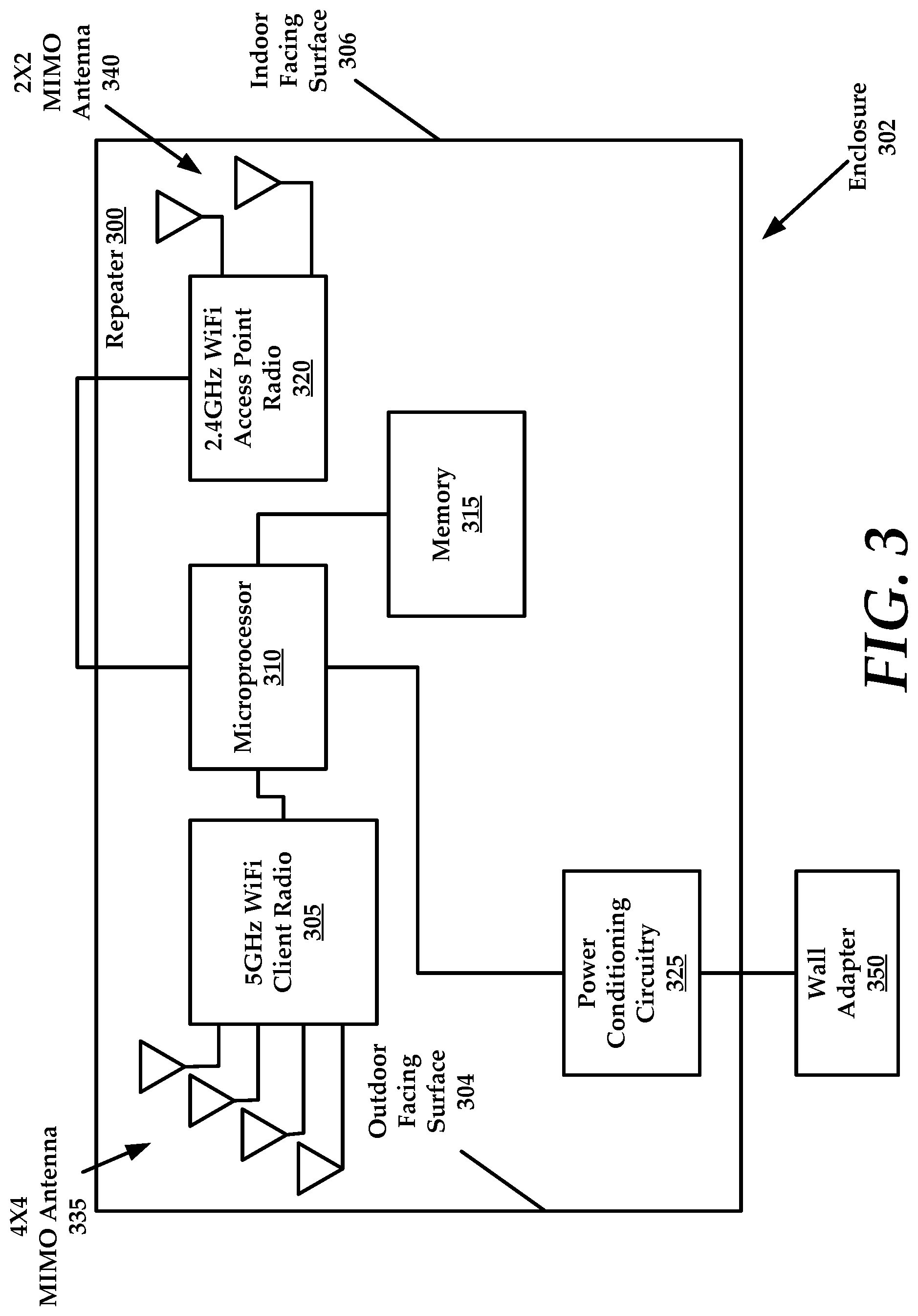
FIG. 3 is a schematic diagram of an example repeater device, constructed in accordance with the present technology.
FIG. 4 is a schematic diagram of an example repeater device that couples with an indoor wireless router.
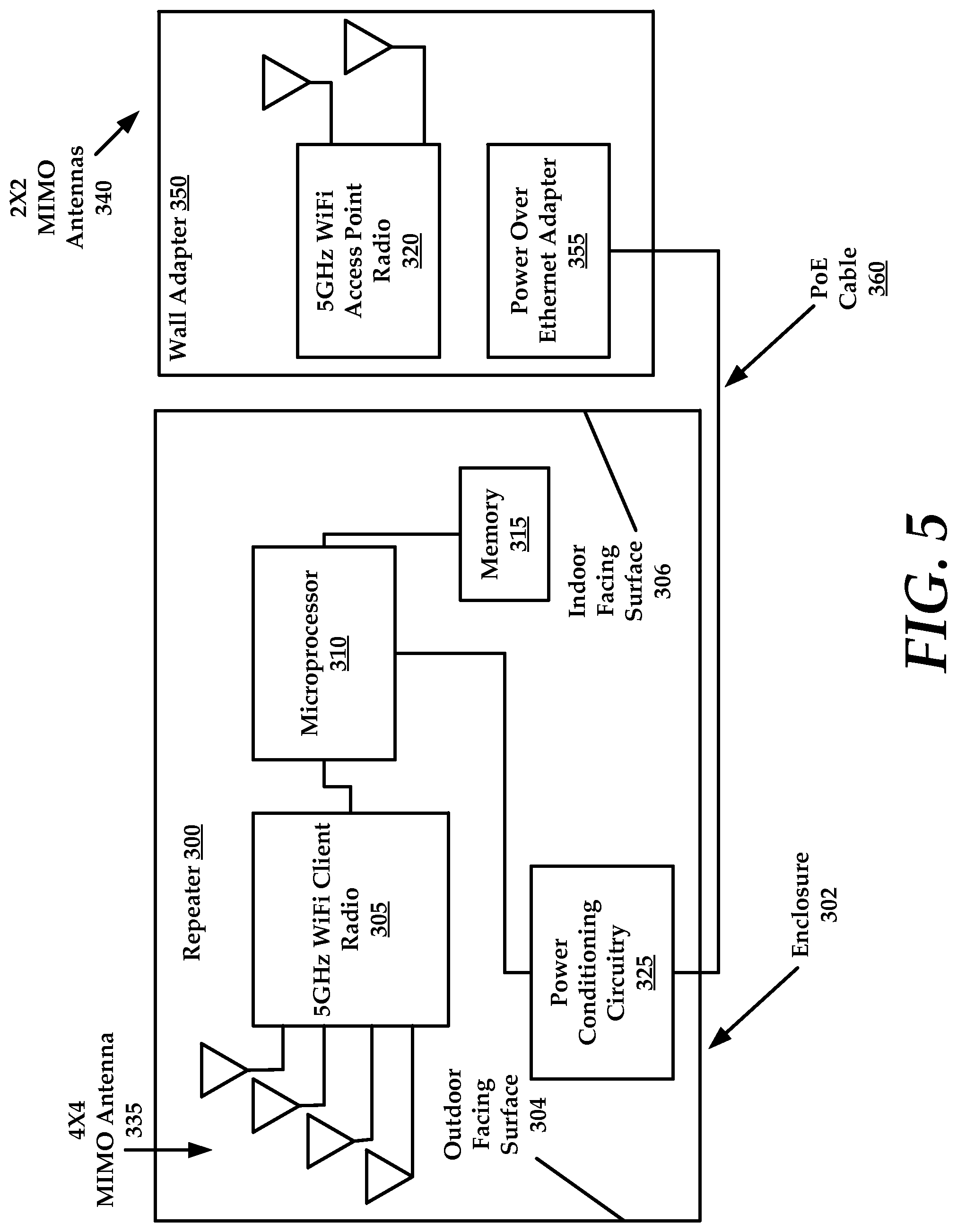
FIG. 5 is a schematic diagram of another example repeater device that couples with an indoor wireless router.
DETAILED DESCRIPTION
In the following description, for purposes of explanation, numerous specific details are set forth in order to provide a thorough understanding of the disclosure. It will be apparent, however, to one skilled in the art, that the disclosure may be practiced without these specific details. In other instances, structures and devices are shown in block diagram form only in order to avoid obscuring the disclosure.
In general, the present technology is directed to a repeater device that functions as a communications gateway between outdoor hotspots, which operate at 5 GHz, and indoor UEs that utilize 2.4 GHz frequency for communication. Broadly, the present technology functions as a WiFi-to-home network gateway.
This repeater device provides a communications gateway that comprises a first radio that operates a first frequency and a second radio that operates on a second frequency. The repeater device includes a microprocessor that is configured to receive and convert data packets having the first frequency into data packets having the second frequency. The repeater device then transmits the converted packets to 2.4 GHz UEs in an indoor area.
Broadly, the microprocessor is configured to convert data packets from 5 GHz to 2.4 GHz and from 2.4 GHz to 5 GHz as needed. For example, data packets received from the 5 GHz WiFi hotspot are converted into 2.4 GHz data packets that are transmitted to UEs in the indoor area.
Similarly, data packets received from the UEs in 2.4 GHz frequency are converted into 5 GHz data packets that are transmitted to the 5 GHz WiFi hotspot. Again, the 5 GHz and 2.4 GHz frequencies are merely example frequencies that can be used. The repeater device can be configured to convert data packets between any two different frequencies and facilitate transmission of the converted data packets between outdoor hotspots and indoor UEs.
With increasing deployment of Metro Wi-Fi hotspots in outdoor settings, it is desirable to leverage that infrastructure for indoor use. In the past, attempts to connect from indoor clients to outdoor access points have been marginally successful. This lack of success is due, in part, to low power clients having low gain antennas that have difficulty coupling with outdoor Wi-Fi hotspots. These connectivity issues are compounded when the path between the indoor client and the outdoor access point is obstructed. For example, obstructions can cause a SNR (signal to noise) in the wireless that is marginal, resulting in a slow transmission speed and high latency due to excessive packet re-transmission. That is, when the SNR is marginal to low, packets transmitted between the indoor clients and outdoor access points are lost and must be re-transmitted.
Referring now to FIGS. 1-3 collectively, the present technology, in one embodiment, comprises a window-mounted Wi-Fi repeater 300 (also referred to herein as the "repeater" or the "repeater device") that is configured to leverage outdoor hotspots for indoor use.
In one embodiment, the repeater 300 comprises a 5 GHz Wi-Fi client (e.g., node) radio 305, a microprocessor 310, memory 315, a 2.4 GHz Wi-Fi access point radio 320, power conditioning circuitry 325, a 4.times.4 MIMO (multiple input, multiple output) antenna 335, and a 2.times.2 MIMO antenna 340.
The 5 GHz Wi-Fi client radio 305 comprises a directional antenna that is positioned toward the outside of the window to pick-up the signal from the 5 GHz access point. A high-order MIMO radio, such as the 4.times.4 MIMO antenna 335 is desirable in the 5 GHz WiFi client radio 305, as antenna beam-forming provided by a high order MIMO radio allows the maximum gain to be steered in a direction that is advantageous for the 5 GHz access point to which the repeater 300 is coupled. The maximum gain point need not be fixed necessarily normal to the window plane.
FIG. 2 illustrates antenna beam-forming relative to a beam-forming plane that is normal N to the window 205. The radiation of the MIMO antenna 335 can be translated upwardly and/or downwardly (as well as side-to side) to direct the antenna radiation as needed. In one instance, the 5 GHz access point is not to be located in a direction that is perfectly linear to the repeater 300. For example, the 5 GHz access point can be position above, below, and/or to the side of the repeater 300. Beam-forming steers the antenna radiation towards the 5 GHz access point so as to maximize signal strength.
Data packets received by the 5 GHz WiFi client radio 305 are processed through a microprocessor 310, and then relayed to a 2.4 GHz Wi-Fi access point radio 320.
With antenna gain toward the inside of the home or office, the 2.4 GHz Wi-Fi access point radio 320 re-transmits the data packets to wireless devices, such as 2.4 GHz User Equipment (UE) that have 2.4 GHz client radios. In the reverse direction, upstream packets from the 2.4 GHz UEs are received by the 2.4 GHz Wi-Fi access point radio 320 of the repeater, over the 2.4 GHz wireless link, processed through the microprocessor 310, and re-transmitted to the 5 GHz access point over the 5 GHz wireless link.
Logic for converting the 5 GHz data packets to 2.4 GHz data packets, and vice-versa is stored in memory 315, as well as beam-forming logic. The microprocessor 310 executes the logic stored in memory 315 to accomplish functions such as beam-forming and data packet conversion, as needed.
In one embodiment, the repeater 300 is enclosed in a plastic enclosure 302 that allows the 2.4 GHz signals (2.4 GHz WiFi Access Point Antenna Pattern 210) and 5 GHz signals (5 GHz WiFi Client Radio Antenna Pattern 215) to reach the respective radios with minimal loss. It is mounted to a window using double-sided adhesive tape 220, allowing it to be removed later, but providing adequate strength for reliable attachment. Other suitable methods for attaching the repeater 300 to a window or other portion of a structure are also likewise contemplated for use in accordance with the present technology.
In one embodiment, the window separates an outdoor area 225 from an indoor area 230. The 5 GHz access point is position in the outdoor area and the 2.4 GHz UEs are positioned in the indoor area. The 4.times.4 MIMO antenna 335 transmits and receives data from a 5 GHz access point located in the outdoor area, while the 2.times.2 MIMO antenna 340 transmits and receives data from a 2.4 GHz UEs located in the indoor area. In one embodiment, the repeater 300 is positioned on the inside of the window within the indoor area. For example, the 5 GHz access point is located in an outside area such as a street lamp, an antenna tower, a building top or other common outdoor location/structure.
The 4.times.4 MIMO antenna 335 is disposed proximate an outdoor facing surface 304 of the enclosure of the repeater 300. Also, the 2.times.2 MIMO antenna 340 is disposed proximate an indoor facing surface 306 of the enclosure of the repeater 300.
As illustrated in FIG. 3, the 5 GHz WiFi client radio 305 transmits and receives data packets through an outdoor oriented surface of the enclosure. The outdoor oriented surface of the enclosure is positioned proximate to and facing the window. The 2.4 GHz WiFi access point radio 320 transmits and receives data packets through an indoor oriented surface of the enclosure. The indoor oriented surface is positioned opposite the outdoor oriented surface.
A data cable such as CAT5E is used to connect the repeater 300 to a power-over-Ethernet wall adapter, such as wall adapter 350, which adapts AC power to low-voltage DC power to operate one or more radios. The data cable coupling the repeater with the wall adapter can comprise a PoE (power over Ethernet) cable. For context, PoE uses an 8-conductor cable that carries both power and Ethernet over four twisted pairs.
The data cable from the repeater 300 could alternatively be a simple two-conductor version and the wall adapter can be a simple AC power converter such as those used for other DC-powered devices. The repeater 300 can use the power conditioning circuitry 325 to adapt the AC power to DC power.
Referring now to FIG. 4, in one embodiment, the repeater 300 can be communicatively coupled with a wireless router 380 that functions as an indoor access point for 2.4 GHz devices located indoors, such as in a home, office, or other building. Thus, the repeater 300 may not require the 2.4 GHz Wi-Fi access point radio 320, but may use a 2.4 GHz Wi-Fi access point radio of the wireless router 380. The repeater 300 can couple with the wireless router also using another data cable 385 that extends from the wall adapter 350. In another embodiment, rather than using a physical data cable 385, the repeater 300 can communicate with the wireless router 380 using the 2.4 GHz Wi-Fi access point radio 320 such that the repeater can be coupled with an existing wireless router 380 in a building. The wireless router 380 will then transmit and receive data from 2.4 GHz UEs 390 in the building.
In some embodiments, the repeater can couple with a dual-band wireless router (e.g., both 2.4 GHz and 5 GHz). The distance between the repeater and the wireless router allows a 5 GHz client and a 5 GHz access point to coexist, without synchronization, provided they are on different channels and far enough apart. This would not be feasible when the client and access point are within the same enclosure though.
In some embodiments, the repeater device 300 (and more specifically the microprocessor) can be configured to provide firewall or other similar security features. That is, the repeater device 300 provides the ability to create a private network within the indoor area using the 2.4 GHz Wi-Fi access point radio 320. Indeed, there may be numerous 2.4 GHz UEs that are joined to the private network created by the repeater device 300. Thus, the repeater device 300 employs network security features to prevent access to the private network from other users that may be using the 5 GHz access point. Similarly, the repeater device 300 can selectively prevent network traffic created on the private network from being transmitted over the 5 GHz network of the 5 GHz access point. Therefore, the repeater device 300 is advantageously capable of providing network address translation functionality to bridge communications between the 5 GHz network of the 5 GHz access point and the private network created for the UEs.
FIG. 5 illustrates another embodiment of a repeater 300 where portions are divided between an enclosure 302 and a wall adapter 350. For example, the enclosure 302 can include the microprocessor 310 and 5 GHz Wi-Fi client radio 305, as well as power conditioning circuitry 325 and memory 315. A second 5 GHz Wi-Fi access point radio 320 and power over Ethernet adapter 355 are positioned in a wall adapter 350. In some embodiments, the second 5 GHz Wi-Fi access point radio 320 can include a dual band radio that utilizes both 2.4 GHz and 5 GHz frequencies.
The second 5 GHz Wi-Fi access point radio 320 can therefore electrically and communicatively couple with the components positioned within the enclosure 302, such as the microprocessor 310 using a power over Ethernet cable 360, or other similar physical power and data connection that would be known to one of ordinary skill in the art. The wall adapter 350 that comprises the second 5 GHz Wi-Fi access point radio 320 and power over Ethernet adapter 355 can be referred to as a PoE gateway.
According to some embodiments, the repeaters described herein can be configured to reduce or eliminate interference on 5 GHz channels. For example, the repeaters can implement a PoE gateway as described above which coordinates with the 5 GHz outdoor access point on a roof of a house, to coordinate 5 GHz channels so as to not cause interference. For example, the microprocessor of the repeater can be configured to pick a new channel when instructed by the 5 GHz access point and dynamically maintaining this function as the outdoor access point may change channels over time.
This methodology is distinguished from clear channel selection methods where an AP or other wireless networking device will scan for an optimal clear channel upon boot up or initialization and/or periodically.
In one embodiment, the 5 GHz Wi-Fi client radio 305 receives data from the 5 GHz access point on a first channel. The microprocessor 310 will utilize the first channel and instruct the second 5 GHz Wi-Fi access point radio 320 to utilize the first channel until instructed to change channels.
According to some embodiments, the 5 GHz access point may determine to select a new channel. For example, if another outdoor access point or other wireless AP in the area begins to utilize portions of the frequency spectrum currently utilized by the 5 GHz outdoor access point, the outdoor access point may selectively change the portion of the spectrum that it utilizes by selecting a new or updated channel.
The outdoor access point transmits a channel change signal that is received by the repeater 300. The repeater 300 receives the channel change signal using the 5 GHz Wi-Fi client radio 305. The microprocessor 310 detects the channel change request and then transmits a request to change of the first channel used by the first radio (5 GHz Wi-Fi client radio 305) and the second 5 GHz Wi-Fi access point radio 320 (also referred to as an access point radio) to a second channel. The UEs communicating with the second 5 GHz Wi-Fi access point radio 320 will detect the channel change and adjust their communication procedures as necessary. In sum, the channel change process includes propagation of a channel change request from the outdoor access point to the window mounted repeater that includes the 5 GHz WiFi client radio 305. The 5 GHz Wi-Fi client radio propagates the channel change request to the second 5 GHz Wi-Fi access point radio 320 disposed in a wall adapter. The channel change request is then propagated out to the UEs that are communicatively coupled with the second 5 GHz WiFi access point radio 320.
To be sure, the 5 GHz Wi-Fi Client Radio 305 can be collocated in the same enclosure with the second 5 GHz Wi-Fi access point radio 320, such as in enclosure 302 as in embodiments disclosed above. In other embodiments, the 5 GHz Wi-Fi Client Radio 305 can be disposed with the enclosure 302 while the second 5 GHz Wi-Fi access point radio 320 is disposed within the wall adapter 350.
In another example embodiment, the wall adapter 350 of FIG. 5 could comprise a 2.4 GHz Wi-Fi access point radio, rather than the second 5 GHz Wi-Fi access point radio 320. The microprocessor 310 can be utilized to control the 2.4 GHz Wi-Fi access point radio 320 as required.
In the following description, for purposes of explanation and not limitation, specific details are set forth, such as particular embodiments, procedures, techniques, etc. in order to provide a thorough understanding of the present invention. However, it will be apparent to one skilled in the art that the present invention may be practiced in other embodiments that depart from these specific details.
Reference throughout this specification to "one embodiment" or "an embodiment" means that a particular feature, structure, or characteristic described in connection with the embodiment is included in at least one embodiment of the present invention. Thus, the appearances of the phrases "in one embodiment" or "in an embodiment" or "according to one embodiment" (or other phrases having similar import) at various places throughout this specification are not necessarily all referring to the same embodiment. Furthermore, the particular features, structures, or characteristics may be combined in any suitable manner in one or more embodiments. Furthermore, depending on the context of discussion herein, a singular term may include its plural forms and a plural term may include its singular form. Similarly, a hyphenated term (e.g., "on-demand") may be occasionally interchangeably used with its non-hyphenated version (e.g., "on demand"), a capitalized entry (e.g., "Software") may be interchangeably used with its non-capitalized version (e.g., "software"), a plural term may be indicated with or without an apostrophe (e.g., PE's or PEs), and an italicized term (e.g., "N+1") may be interchangeably used with its non-italicized version (e.g., "N+1"). Such occasional interchangeable uses shall not be considered inconsistent with each other.
Also, some embodiments may be described in terms of "means for" performing a task or set of tasks. It will be understood that a "means for" may be expressed herein in terms of a structure, such as a processor, a memory, an I/O device such as a camera, or combinations thereof. Alternatively, the "means for" may include an algorithm that is descriptive of a function or method step, while in yet other embodiments the "means for" is expressed in terms of a mathematical formula, prose, or as a flow chart or signal diagram.
The terminology used herein is for the purpose of describing particular embodiments only and is not intended to be limiting of the invention. As used herein, the singular forms "a", "an" and "the" are intended to include the plural forms as well, unless the context clearly indicates otherwise. It will be further understood that the terms "comprises" and/or "comprising," when used in this specification, specify the presence of stated features, integers, steps, operations, elements, and/or components, but do not preclude the presence or addition of one or more other features, integers, steps, operations, elements, components, and/or groups thereof.
It is noted at the outset that the terms "coupled," "connected", "connecting," "electrically connected," etc., are used interchangeably herein to generally refer to the condition of being electrically/electronically connected. Similarly, a first entity is considered to be in "communication" with a second entity (or entities) when the first entity electrically sends and/or receives (whether through wireline or wireless means) information signals (whether containing data information or non-data/control information) to the second entity regardless of the type (analog or digital) of those signals. It is further noted that various figures (including component diagrams) shown and discussed herein are for illustrative purpose only, and are not drawn to scale.
While various embodiments have been described above, it should be understood that they have been presented by way of example only, and not limitation. The descriptions are not intended to limit the scope of the invention to the particular forms set forth herein. To the contrary, the present descriptions are intended to cover such alternatives, modifications, and equivalents as may be included within the spirit and scope of the invention as defined by the appended claims and otherwise appreciated by one of ordinary skill in the art. Thus, the breadth and scope of a preferred embodiment should not be limited by any of the above-described exemplary embodiments.
* * * * *
References
D00000
D00001
D00002
D00003
D00004
D00005
XML
uspto.report is an independent third-party trademark research tool that is not affiliated, endorsed, or sponsored by the United States Patent and Trademark Office (USPTO) or any other governmental organization. The information provided by uspto.report is based on publicly available data at the time of writing and is intended for informational purposes only.
While we strive to provide accurate and up-to-date information, we do not guarantee the accuracy, completeness, reliability, or suitability of the information displayed on this site. The use of this site is at your own risk. Any reliance you place on such information is therefore strictly at your own risk.
All official trademark data, including owner information, should be verified by visiting the official USPTO website at www.uspto.gov. This site is not intended to replace professional legal advice and should not be used as a substitute for consulting with a legal professional who is knowledgeable about trademark law.