Non-pneumatic tire and other annular devices
Thompson March 23, 2
U.S. patent number 10,953,696 [Application Number 15/549,024] was granted by the patent office on 2021-03-23 for non-pneumatic tire and other annular devices. This patent grant is currently assigned to CAMSO INC. The grantee listed for this patent is CAMSO INC.. Invention is credited to Ronald H. Thompson.


View All Diagrams
| United States Patent | 10,953,696 |
| Thompson | March 23, 2021 |
Non-pneumatic tire and other annular devices
Abstract
A non-pneumatic tire for a vehicle or other machine. The non-pneumatic tire may include an annular beam. The annular beam may include a plurality of layers of different elastomeric materials. The annular beam may be free of a substantially inextensible reinforcing layer running in a circumferential direction of the non-pneumatic tire. The annular beam may include a plurality of openings distributed in the circumferential direction of the non-pneumatic tire. Such an annular beam may be part of other annular devices.
| Inventors: | Thompson; Ronald H. (Greenville, SC) | ||||||||||
|---|---|---|---|---|---|---|---|---|---|---|---|
| Applicant: |
|
||||||||||
| Assignee: | CAMSO INC (Magog,
CA) |
||||||||||
| Family ID: | 1000005437873 | ||||||||||
| Appl. No.: | 15/549,024 | ||||||||||
| Filed: | February 4, 2016 | ||||||||||
| PCT Filed: | February 04, 2016 | ||||||||||
| PCT No.: | PCT/US2016/016630 | ||||||||||
| 371(c)(1),(2),(4) Date: | August 04, 2017 | ||||||||||
| PCT Pub. No.: | WO2016/126983 | ||||||||||
| PCT Pub. Date: | August 11, 2016 |
Prior Publication Data
| Document Identifier | Publication Date | |
|---|---|---|
| US 20180029422 A1 | Feb 1, 2018 | |
Related U.S. Patent Documents
| Application Number | Filing Date | Patent Number | Issue Date | ||
|---|---|---|---|---|---|
| 62111872 | Feb 4, 2015 | ||||
| Current U.S. Class: | 1/1 |
| Current CPC Class: | B60C 11/0311 (20130101); B60C 9/1807 (20130101); B60C 9/18 (20130101); B60C 11/0041 (20130101); B60C 7/10 (20130101); B60C 7/18 (20130101); B60C 2007/146 (20130101); B60C 2011/0025 (20130101); B60C 2011/0388 (20130101) |
| Current International Class: | B60C 7/00 (20060101); B60C 11/03 (20060101); B60C 9/18 (20060101); B60C 11/00 (20060101); B60C 7/10 (20060101); B60C 7/18 (20060101); B60C 7/14 (20060101) |
References Cited [Referenced By]
U.S. Patent Documents
| 2704102 | March 1955 | Starr et al. |
| 3494402 | February 1970 | Goldberger |
| 3804144 | April 1974 | Sand, Sr. |
| 3814158 | June 1974 | Ryder |
| 3827792 | August 1974 | Hollins |
| 3901300 | August 1975 | Toplis |
| 3907370 | September 1975 | Bard |
| 3957101 | May 1976 | Ippen et al. |
| 4044811 | August 1977 | Dudek |
| 4164251 | August 1979 | Chung |
| 4169494 | October 1979 | Kubica et al. |
| 4201744 | May 1980 | Makinson |
| 4226273 | October 1980 | Long et al. |
| 4235270 | November 1980 | Kahaner et al. |
| 4244413 | January 1981 | Takahashi et al. |
| 4253893 | March 1981 | Clinefelter |
| 4262724 | April 1981 | Sarkissian |
| 4273176 | June 1981 | Wyman et al. |
| 4281700 | August 1981 | Ross |
| 4287927 | September 1981 | Caravito et al. |
| 4310042 | January 1982 | Wyman et al. |
| 4345633 | August 1982 | Gilmore |
| 4350196 | September 1982 | Hampshire |
| 4387071 | June 1983 | Kirkhuff |
| 4446903 | May 1984 | Clinefelter et al. |
| 4471827 | July 1984 | Czapar |
| 4558727 | December 1985 | Golata et al. |
| 4580610 | April 1986 | Jackson |
| 4705087 | November 1987 | Markow |
| 4739810 | April 1988 | Markow |
| 4773461 | September 1988 | Landers et al. |
| 4784201 | November 1988 | Palinkas et al. |
| 4832098 | May 1989 | Palinkas et al. |
| 4867217 | September 1989 | Laurent |
| 4917162 | April 1990 | De Longcamp |
| 4921029 | May 1990 | Palinkas et al. |
| 4934425 | June 1990 | Gajewski et al. |
| 4945962 | August 1990 | Pajtas |
| 4966212 | October 1990 | Hill |
| 5023040 | June 1991 | Gajewski et al. |
| 5024028 | June 1991 | Pierce et al. |
| 5042544 | August 1991 | Dehasse |
| 5050656 | September 1991 | Ho |
| 5086815 | February 1992 | Panaroni et al. |
| 5090464 | February 1992 | Kauzlarich et al. |
| 5139066 | August 1992 | Jarman |
| 5168910 | December 1992 | Zhang et al. |
| 5174634 | December 1992 | Blanck et al. |
| 5223599 | June 1993 | Gajewski |
| 5236027 | August 1993 | Lu |
| 5265659 | November 1993 | Pajtas et al. |
| 5313994 | May 1994 | Hill, III et al. |
| 5343916 | September 1994 | Duddey et al. |
| 5353853 | October 1994 | Hansson |
| 5460213 | October 1995 | Pajtas |
| 5494090 | February 1996 | Kejha |
| 5520232 | May 1996 | Fukutake et al. |
| 5676900 | October 1997 | Pajtas |
| 5743316 | April 1998 | Chrobak |
| 5879482 | March 1999 | Rooney et al. |
| 6068353 | May 2000 | Juncker et al. |
| 6095216 | August 2000 | Cenni et al. |
| 6167931 | January 2001 | Hsiao |
| 6170544 | January 2001 | Hottebart |
| 6279630 | August 2001 | Herbert Ims |
| 6298891 | October 2001 | Harris |
| 6364424 | January 2002 | Lashlee et al. |
| 6431235 | August 2002 | Steinke |
| 6450222 | September 2002 | Fleming |
| 6530404 | March 2003 | Rooney |
| 6615885 | September 2003 | Ohm |
| 6617383 | September 2003 | Ikawa et al. |
| 6640859 | November 2003 | Laurent et al. |
| 6640861 | November 2003 | Pereira et al. |
| 6681822 | January 2004 | Adams et al. |
| 6698480 | March 2004 | Cornellier |
| 6767495 | July 2004 | Aperce et al. |
| 6769465 | August 2004 | Rhyne et al. |
| 6769746 | August 2004 | Rodgers et al. |
| 6820942 | November 2004 | Knack |
| 6983776 | January 2006 | Thompson et al. |
| 6994134 | February 2006 | Grah |
| 6994135 | February 2006 | Delfino et al. |
| 7013939 | March 2006 | Rhyne et al. |
| 7032634 | April 2006 | Laurent et al. |
| 7032637 | April 2006 | Meraldi |
| 7044180 | May 2006 | Rhyne et al. |
| 7066225 | June 2006 | Rhyne et al. |
| 7128479 | October 2006 | Veas |
| 7128794 | October 2006 | Veas |
| 7159632 | January 2007 | Fukui |
| 7201194 | April 2007 | Rhyne et al. |
| 7231948 | June 2007 | Forney, III et al. |
| 7281558 | October 2007 | Merino Lopez |
| 7329325 | February 2008 | Prost |
| 7418988 | September 2008 | Cron et al. |
| 7473472 | January 2009 | Chenaux et al. |
| 7506878 | March 2009 | Feick |
| 7546862 | June 2009 | Moon et al. |
| 7604029 | October 2009 | Myatt |
| 7650919 | January 2010 | Rhyne et al. |
| 7743806 | June 2010 | Abe |
| 7832263 | November 2010 | Rensel et al. |
| 7950428 | May 2011 | Hanada et al. |
| 7950429 | May 2011 | Re Fiorentin et al. |
| 8056593 | November 2011 | Palinkas et al. |
| 8061398 | November 2011 | Palinkas et al. |
| 8091596 | January 2012 | Louden |
| 8104524 | January 2012 | Manesh et al. |
| 8109308 | February 2012 | Manesh et al. |
| 8113253 | February 2012 | Arakawa et al. |
| 8141606 | March 2012 | Benzing, II et al. |
| 8166809 | May 2012 | Weston |
| 8176957 | May 2012 | Manesh et al. |
| 8215351 | May 2012 | Thompson |
| 8276628 | October 2012 | Hanada et al. |
| 8277590 | October 2012 | Delfino et al. |
| 8419408 | April 2013 | Wang |
| 8476808 | July 2013 | Weston et al. |
| 8491981 | July 2013 | Delfino et al. |
| 8517068 | August 2013 | Delfino et al. |
| 8544515 | October 2013 | Ma et al. |
| 8555941 | October 2013 | Chadwick et al. |
| 8567461 | October 2013 | Williams et al. |
| 8578607 | November 2013 | Kim |
| 8585947 | November 2013 | Meraldi et al. |
| 8609220 | December 2013 | Summers et al. |
| 8623169 | January 2014 | Delfino et al. |
| 8631844 | January 2014 | Anderfaas et al. |
| 8636490 | January 2014 | Martin et al. |
| 8646497 | February 2014 | Cron |
| 8651156 | February 2014 | Fadel et al. |
| 8662122 | March 2014 | Benzing, II |
| 8672006 | March 2014 | Moon |
| 8688421 | April 2014 | Summers et al. |
| 8714217 | May 2014 | Chon et al. |
| 8720504 | May 2014 | Benzing, II et al. |
| 8720505 | May 2014 | Fiorentin et al. |
| 8742265 | June 2014 | Weston et al. |
| 8746302 | June 2014 | Sachdev et al. |
| 8751270 | June 2014 | Hanson et al. |
| 8783310 | July 2014 | Abe |
| D711815 | August 2014 | Abe et al. |
| 8813797 | August 2014 | Anderson et al. |
| 8827383 | September 2014 | Simula |
| 8851131 | October 2014 | Luchini et al. |
| 8863798 | October 2014 | Re Fiorentin et al. |
| 8883283 | November 2014 | Delfino et al. |
| 8919404 | December 2014 | Schweitzer et al. |
| 8931531 | January 2015 | Kubeck et al. |
| 8950451 | February 2015 | Abe |
| 8960248 | February 2015 | Cron et al. |
| 8962120 | February 2015 | Delfino et al. |
| 8944125 | March 2015 | Manesh et al. |
| 8978723 | March 2015 | McCulley |
| 8991455 | March 2015 | Cron |
| 8999480 | April 2015 | Summers et al. |
| 9004127 | April 2015 | Manesh et al. |
| 9004901 | April 2015 | Wilson |
| 9016336 | April 2015 | Benzing, II et al. |
| 9027615 | May 2015 | Dermience et al. |
| D731958 | June 2015 | Kiwaki |
| 9090121 | July 2015 | Korus et al. |
| 9108470 | August 2015 | Tercha et al. |
| 9120351 | September 2015 | Mun et al. |
| 9139045 | September 2015 | Palinkas et al. |
| 9144946 | September 2015 | Creasap et al. |
| 9149994 | October 2015 | Martin et al. |
| 9156313 | October 2015 | Thompson |
| 9162407 | October 2015 | Martin et al. |
| 9180732 | November 2015 | Endicott |
| 9180737 | November 2015 | Amstutz et al. |
| 9186934 | November 2015 | Korus |
| 9205706 | December 2015 | Kline et al. |
| 9242509 | January 2016 | Chang |
| 9242510 | January 2016 | Korus |
| 9248697 | February 2016 | Iwamura |
| 9254716 | February 2016 | Cron et al. |
| 9266388 | February 2016 | Schaedler et al. |
| 9266506 | February 2016 | Korus et al. |
| 9272576 | March 2016 | Dotson et al. |
| 9278494 | March 2016 | Anderson et al. |
| 9283806 | March 2016 | Korus et al. |
| 9283810 | March 2016 | Korus et al. |
| 9283811 | March 2016 | Kim |
| 9290045 | March 2016 | Cron |
| 9290053 | March 2016 | Choi et al. |
| 9290054 | March 2016 | Pfrenger et al. |
| 9290059 | March 2016 | Fredenburg et al. |
| 9302539 | April 2016 | Korus et al. |
| 9321312 | April 2016 | Asper |
| 9333799 | May 2016 | Choi et al. |
| 9346317 | May 2016 | Dotson et al. |
| 9346499 | May 2016 | Rudakevych et al. |
| 9352617 | May 2016 | Zhang |
| 9358704 | June 2016 | Kagota et al. |
| 9381773 | July 2016 | Seljan |
| 9387637 | July 2016 | Martin et al. |
| 9387726 | July 2016 | Choi et al. |
| 9393835 | July 2016 | Dotson et al. |
| D763785 | August 2016 | Abe et al. |
| 9421820 | August 2016 | Wilson et al. |
| 9440404 | September 2016 | Martin |
| 9440494 | September 2016 | Asper |
| 9463603 | October 2016 | Chadwick et al. |
| 9463668 | October 2016 | Fredenburg et al. |
| 9475244 | October 2016 | Williams et al. |
| 9475379 | October 2016 | Imamiya et al. |
| 9481208 | November 2016 | Matsuda et al. |
| 9487046 | November 2016 | Amstutz et al. |
| 9487052 | November 2016 | Asper |
| 9487892 | November 2016 | Abad |
| 9493045 | November 2016 | Cron et al. |
| 9511625 | December 2016 | Nishida et al. |
| 9511631 | December 2016 | Fudemoto et al. |
| 9511632 | December 2016 | Fudemoto et al. |
| 9550393 | January 2017 | Abe et al. |
| 9573422 | February 2017 | Gass et al. |
| 9573622 | February 2017 | Fujita et al. |
| 9604497 | March 2017 | Korus et al. |
| 9616703 | April 2017 | Nishida et al. |
| 9616713 | April 2017 | Lettieri et al. |
| 9623702 | April 2017 | Fudemoto et al. |
| 9643453 | May 2017 | Dotson et al. |
| 9662936 | May 2017 | Slanker et al. |
| 9662939 | May 2017 | Manesh et al. |
| 9713940 | July 2017 | Nishida et al. |
| 9718306 | August 2017 | Korus et al. |
| 9731556 | August 2017 | Martin et al. |
| 9751270 | September 2017 | Thompson |
| 9758002 | September 2017 | Carter et al. |
| 9776454 | October 2017 | Chen |
| 9821601 | November 2017 | Korus et al. |
| 9834040 | December 2017 | Benzing, II et al. |
| 9939835 | April 2018 | Watanabe |
| 10166732 | January 2019 | Thompson |
| 2003/0201043 | October 2003 | Adams et al. |
| 2004/0007300 | January 2004 | Foucher |
| 2004/0012246 | January 2004 | Rhyne et al. |
| 2004/0112491 | June 2004 | Grah |
| 2006/0005903 | January 2006 | Fry et al. |
| 2006/0040077 | February 2006 | Wilson et al. |
| 2006/0060280 | March 2006 | Ladouce et al. |
| 2006/0102264 | May 2006 | Nicolas |
| 2006/0113016 | June 2006 | Cron et al. |
| 2006/0169797 | August 2006 | Kaltenheuser |
| 2006/0201597 | September 2006 | Lacour |
| 2006/0249235 | November 2006 | Lacour |
| 2007/0119531 | May 2007 | Steinke et al. |
| 2007/0200265 | August 2007 | Forney, III et al. |
| 2007/0267116 | November 2007 | Rhyne et al. |
| 2008/0029215 | February 2008 | Delfino et al. |
| 2008/0257463 | October 2008 | Re Fiorentin et al. |
| 2009/0107596 | April 2009 | Palinkas et al. |
| 2009/0183810 | July 2009 | Vannan et al. |
| 2009/0211677 | August 2009 | Palinkas et al. |
| 2009/0211681 | August 2009 | Palinkas et al. |
| 2009/0250149 | October 2009 | Sebe |
| 2009/0294000 | December 2009 | Cron |
| 2009/0301625 | December 2009 | Moon et al. |
| 2010/0071819 | March 2010 | McCulley |
| 2010/0078111 | April 2010 | Anderson et al. |
| 2010/0132858 | June 2010 | Arakawa et al. |
| 2010/0132865 | June 2010 | Iwase et al. |
| 2010/0154948 | June 2010 | Dahlberg et al. |
| 2010/0193097 | August 2010 | McNier et al. |
| 2010/0200131 | August 2010 | Iwase et al. |
| 2011/0017377 | January 2011 | Albert et al. |
| 2011/0079336 | April 2011 | Thenault et al. |
| 2011/0104428 | May 2011 | Delfino et al. |
| 2011/0146872 | June 2011 | Tercha et al. |
| 2011/0180194 | July 2011 | Anderson et al. |
| 2011/0240193 | October 2011 | Matsuda et al. |
| 2011/0253281 | October 2011 | Christenbury |
| 2011/0265926 | November 2011 | De Staercke |
| 2011/0278911 | November 2011 | Funaki |
| 2012/0038206 | February 2012 | Chadwick et al. |
| 2012/0038207 | February 2012 | Williams et al. |
| 2012/0193004 | August 2012 | Anderson et al. |
| 2012/0216932 | August 2012 | Cron et al. |
| 2012/0234444 | September 2012 | Palinkas et al. |
| 2012/0234445 | September 2012 | Manesh et al. |
| 2012/0241531 | September 2012 | Werner |
| 2012/0247635 | October 2012 | Manesh et al. |
| 2012/0318421 | December 2012 | Matsuda et al. |
| 2013/0048171 | February 2013 | Sandstrom et al. |
| 2013/0048174 | February 2013 | Cron |
| 2013/0150516 | June 2013 | Lettow |
| 2013/0167990 | July 2013 | Bae |
| 2013/0233458 | September 2013 | Meraldi et al. |
| 2013/0240097 | September 2013 | Cron et al. |
| 2013/0248067 | September 2013 | Delfino et al. |
| 2013/0276968 | October 2013 | Moore |
| 2013/0278045 | October 2013 | Dotson |
| 2013/0284329 | October 2013 | Wilson et al. |
| 2013/0340902 | December 2013 | Kemeny |
| 2014/0062168 | March 2014 | Martin et al. |
| 2014/0062169 | March 2014 | Martin et al. |
| 2014/0062170 | March 2014 | Martin et al. |
| 2014/0062171 | March 2014 | Martin et al. |
| 2014/0062172 | March 2014 | Martin et al. |
| 2014/0070460 | March 2014 | Martin et al. |
| 2014/0083581 | March 2014 | Schaedler et al. |
| 2014/0110028 | April 2014 | Benzing, II |
| 2014/0159280 | June 2014 | Martin et al. |
| 2014/0191564 | July 2014 | Gebeau |
| 2014/0191565 | July 2014 | Gebeau |
| 2014/0205836 | July 2014 | Hidrot et al. |
| 2014/0238561 | August 2014 | Choi et al. |
| 2014/0246135 | September 2014 | Andrews |
| 2014/0251518 | September 2014 | Abe et al. |
| 2014/0326374 | November 2014 | Cron et al. |
| 2014/0367007 | December 2014 | Thompson |
| 2015/0007926 | January 2015 | Sandstrom et al. |
| 2015/0013871 | January 2015 | McEwen et al. |
| 2015/0034222 | February 2015 | Martin et al. |
| 2015/0034225 | February 2015 | Martin |
| 2015/0048547 | February 2015 | Benzing, II |
| 2015/0083296 | March 2015 | Asper |
| 2015/0096654 | April 2015 | Sandstrom et al. |
| 2015/0122385 | May 2015 | Cron et al. |
| 2015/0158337 | June 2015 | Korus et al. |
| 2015/0174953 | June 2015 | Cron et al. |
| 2015/0191157 | July 2015 | Korus et al. |
| 2015/0210025 | July 2015 | Martin |
| 2015/0246577 | September 2015 | Fudemoto et al. |
| 2015/0251493 | September 2015 | Ma |
| 2015/0273945 | October 2015 | Fudemoto et al. |
| 2015/0273946 | October 2015 | Abe et al. |
| 2015/0283852 | October 2015 | Chen et al. |
| 2015/0283856 | October 2015 | Pfrenger et al. |
| 2015/0343840 | December 2015 | Kinney et al. |
| 2015/0343845 | December 2015 | Kinney et al. |
| 2016/0016426 | January 2016 | Endicott |
| 2016/0046091 | February 2016 | Kinney et al. |
| 2016/0046092 | February 2016 | Kinney et al. |
| 2016/0046153 | February 2016 | Yoo |
| 2016/0046154 | February 2016 | Kim |
| 2016/0096400 | April 2016 | Nomura et al. |
| 2016/0107402 | April 2016 | Cron et al. |
| 2016/0121656 | May 2016 | Sugiya et al. |
| 2016/0128266 | May 2016 | Phely et al. |
| 2016/0152078 | June 2016 | Korus et al. |
| 2016/0159150 | June 2016 | Pfrenger et al. |
| 2016/0159152 | June 2016 | Delfino et al. |
| 2016/0167434 | June 2016 | Nishida et al. |
| 2016/0193876 | July 2016 | Kyo et al. |
| 2016/0193877 | July 2016 | Jang et al. |
| 2016/0200144 | July 2016 | Iwamura et al. |
| 2016/0214435 | July 2016 | Schaedler |
| 2016/0221284 | August 2016 | Andrews et al. |
| 2016/0236514 | August 2016 | Abe |
| 2016/0250893 | September 2016 | Shoji et al. |
| 2016/0257170 | September 2016 | Sugiya et al. |
| 2016/0272006 | September 2016 | Abe |
| 2016/0280005 | September 2016 | Cron et al. |
| 2016/0288569 | October 2016 | Parrondry et al. |
| 2016/0297244 | October 2016 | Abe |
| 2016/0303812 | October 2016 | LePretre et al. |
| 2016/0311479 | October 2016 | Rudakevych |
| 2016/0312014 | October 2016 | Lemerle et al. |
| 2016/0318342 | November 2016 | Deltino |
| 2016/0319111 | November 2016 | Chouvel et al. |
| 2016/0347119 | December 2016 | Quiroz |
| 2017/0001470 | January 2017 | Merino Lopez |
| 2017/0008338 | January 2017 | Merino Lopez |
| 2017/0008341 | January 2017 | Martin |
| 2017/0008342 | January 2017 | Martin et al. |
| 2017/0015134 | January 2017 | Ma |
| 2017/0015141 | January 2017 | Shoji et al. |
| 2017/0057288 | March 2017 | Sugiya et al. |
| 2017/0057289 | March 2017 | Pratt |
| 2017/0057294 | March 2017 | Iwamura et al. |
| 2017/0072746 | March 2017 | Iwamura et al. |
| 2017/0080756 | March 2017 | Van Riper et al. |
| 2017/0087930 | March 2017 | McMaster et al. |
| 2017/0087931 | March 2017 | Gaylo et al. |
| 2017/0087937 | March 2017 | Korus et al. |
| 2017/0096032 | April 2017 | Iwamura et al. |
| 2017/0106699 | April 2017 | Iwamura et al. |
| 2017/0113484 | April 2017 | Iwamura et al. |
| 2017/0113488 | April 2017 | Iwamura et al. |
| 2017/0113490 | April 2017 | Iwamura et al. |
| 2017/0113491 | April 2017 | Iwamura et al. |
| 2017/0120671 | May 2017 | Miles et al. |
| 2017/0120680 | May 2017 | Takahashi et al. |
| 2017/0120681 | May 2017 | Toyosawa |
| 2017/0129285 | May 2017 | Toyosawa |
| 2017/0136814 | May 2017 | Abe et al. |
| 2017/0157983 | June 2017 | Siegel |
| 2017/0157984 | June 2017 | Van Riper et al. |
| 2017/0166002 | June 2017 | Benzing, II et al. |
| 2017/0174002 | June 2017 | Downing |
| 2017/0174003 | June 2017 | Benzing, II et al. |
| 2017/0174004 | June 2017 | Benzing, II |
| 2017/0174005 | June 2017 | Van Riper et al. |
| 2017/0197467 | July 2017 | Iwamura et al. |
| 2017/0232787 | August 2017 | Hasegawa et al. |
| 2017/0239994 | August 2017 | Raulerson et al. |
| 2017/0253084 | September 2017 | Takahashi et al. |
| 2017/0267028 | September 2017 | Pfrenger et al. |
| 2017/0291453 | October 2017 | Sugiya et al. |
| 2017/0297370 | October 2017 | Korus et al. |
| 2017/0297371 | October 2017 | Sportelli |
| 2017/0297372 | October 2017 | Talbot et al. |
| 2017/0297373 | October 2017 | Sportelli |
| 2017/0297374 | October 2017 | Sportelli |
| 2017/0305192 | October 2017 | Yokoyama |
| 2017/0305195 | October 2017 | Takahashi et al. |
| 2017/0326915 | November 2017 | Son et al. |
| 2017/0334245 | November 2017 | Laskowitz |
| 2017/0368775 | December 2017 | Thompson |
| 2018/0001699 | January 2018 | Shoji |
| 2019/0111645 | April 2019 | Thompson |
| 2020/0009916 | January 2020 | Thompson et al. |
| 2458002 | Aug 2010 | CA | |||
| 2651523 | Feb 2012 | CA | |||
| 2915483 | Dec 2014 | CA | |||
| 2976055 | Aug 2016 | CA | |||
| 3006801 | Jun 2017 | CA | |||
| 3008828 | Jun 2017 | CA | |||
| 3008846 | Jun 2017 | CA | |||
| 0502353 | Sep 1992 | EP | |||
| 0334522 | Nov 1994 | EP | |||
| 1378377 | Jan 2004 | EP | |||
| 0353006 | Jan 2009 | EP | |||
| 3923073 | May 2007 | JP | |||
| 2011-219009 | Nov 2011 | JP | |||
| 2002956 | Dec 2010 | NL | |||
| 96/05917 | Feb 1996 | WO | |||
| 2000018592 | Apr 2000 | WO | |||
| 2000037269 | Jun 2000 | WO | |||
| 2006022788 | Mar 2006 | WO | |||
| 2008/045098 | Apr 2008 | WO | |||
| 2008118983 | Oct 2008 | WO | |||
| 2009005945 | Jan 2009 | WO | |||
| 2009005946 | Jan 2009 | WO | |||
| 2009042460 | Apr 2009 | WO | |||
| 2010138150 | Dec 2010 | WO | |||
| 2011011419 | Jan 2011 | WO | |||
| 2013095499 | Jun 2013 | WO | |||
| 2014036415 | Mar 2014 | WO | |||
| 2014039814 | Mar 2014 | WO | |||
| 2014093135 | Jun 2014 | WO | |||
| 2014172095 | Oct 2014 | WO | |||
| 2015013036 | Jan 2015 | WO | |||
| 2015017100 | Feb 2015 | WO | |||
| 2015017133 | Feb 2015 | WO | |||
| 2015023969 | Feb 2015 | WO | |||
| 2015052987 | Apr 2015 | WO | |||
| 2015072222 | May 2015 | WO | |||
| 2015100080 | Jul 2015 | WO | |||
| 2015112417 | Jul 2015 | WO | |||
| 2015112720 | Jul 2015 | WO | |||
| 2015141579 | Sep 2015 | WO | |||
| 2015165777 | Nov 2015 | WO | |||
| 2015175002 | Nov 2015 | WO | |||
| 2015175003 | Nov 2015 | WO | |||
| 2015187394 | Dec 2015 | WO | |||
| 2015194087 | Dec 2015 | WO | |||
| 2015194088 | Dec 2015 | WO | |||
| 2015194277 | Dec 2015 | WO | |||
| 2015198387 | Dec 2015 | WO | |||
| 2015198637 | Dec 2015 | WO | |||
| 2016021300 | Feb 2016 | WO | |||
| 2016056444 | Apr 2016 | WO | |||
| 2016072181 | May 2016 | WO | |||
| 2016084512 | Jun 2016 | WO | |||
| 2016089480 | Jun 2016 | WO | |||
| 2016098477 | Jun 2016 | WO | |||
| 2016100004 | Jun 2016 | WO | |||
| 2016100005 | Jun 2016 | WO | |||
| 2016100006 | Jun 2016 | WO | |||
| 2016105654 | Jun 2016 | WO | |||
| 2016109557 | Jul 2016 | WO | |||
| 2016109648 | Jul 2016 | WO | |||
| 2016109702 | Jul 2016 | WO | |||
| 2016114167 | Jul 2016 | WO | |||
| 2016114168 | Jul 2016 | WO | |||
| 2016116457 | Jul 2016 | WO | |||
| 2016/126983 | Aug 2016 | WO | |||
| 2016123180 | Aug 2016 | WO | |||
| 2016148295 | Sep 2016 | WO | |||
| 2016152887 | Sep 2016 | WO | |||
| 2016189126 | Dec 2016 | WO | |||
| 2016189209 | Dec 2016 | WO | |||
| 2016203098 | Dec 2016 | WO | |||
| 2017024366 | Feb 2017 | WO | |||
| 2017035630 | Mar 2017 | WO | |||
| 2017039451 | Mar 2017 | WO | |||
| 2017039604 | Mar 2017 | WO | |||
| 2017040390 | Mar 2017 | WO | |||
| 2017052010 | Mar 2017 | WO | |||
| 2017061405 | Apr 2017 | WO | |||
| 2017067869 | Apr 2017 | WO | |||
| 2017072560 | May 2017 | WO | |||
| 2017072562 | May 2017 | WO | |||
| 2017086993 | May 2017 | WO | |||
| 2017087853 | May 2017 | WO | |||
| 2017/106704 | Jun 2017 | WO | |||
| 2017/106723 | Jun 2017 | WO | |||
| 2017110769 | Jun 2017 | WO | |||
| 2017111944 | Jun 2017 | WO | |||
| 2017112130 | Jun 2017 | WO | |||
| 2017116384 | Jul 2017 | WO | |||
| 2017116385 | Jul 2017 | WO | |||
| 2017116386 | Jul 2017 | WO | |||
| 2017116389 | Jul 2017 | WO | |||
| 2017116390 | Jul 2017 | WO | |||
| 2017116454 | Jul 2017 | WO | |||
| 2017116463 | Jul 2017 | WO | |||
| 2017116472 | Jul 2017 | WO | |||
| 2017116475 | Jul 2017 | WO | |||
| 2017116478 | Jul 2017 | WO | |||
| 2017116481 | Jul 2017 | WO | |||
| 2017116556 | Jul 2017 | WO | |||
| 2017116557 | Jul 2017 | WO | |||
| 2017116561 | Jul 2017 | WO | |||
| 2017116565 | Jul 2017 | WO | |||
| 2017116804 | Jul 2017 | WO | |||
| 2017117365 | Jul 2017 | WO | |||
| 2017117368 | Jul 2017 | WO | |||
| 2017117587 | Jul 2017 | WO | |||
| 2017117598 | Jul 2017 | WO | |||
| 2017117599 | Jul 2017 | WO | |||
| 2017117605 | Jul 2017 | WO | |||
| 2017117606 | Jul 2017 | WO | |||
| 2017131742 | Aug 2017 | WO | |||
| 2017159899 | Sep 2017 | WO | |||
| 2017200645 | Nov 2017 | WO | |||
| 2018/111339 | Jun 2018 | WO | |||
| 2018/112650 | Jun 2018 | WO | |||
| 2018/227276 | Dec 2018 | WO | |||
| 2019/119155 | Jun 2019 | WO | |||
Other References
|
https://en.wikipedia.org/wiki/Shear_modulus, no date. cited by examiner . https://en.wikipedia.org/wiki/Poisson%27s_ratio, no date. cited by examiner . Aug. 16, 2018 Search Report issued in European Patent Application No. 16747290.1. cited by applicant . May 24, 2019 Search Report issued in European Patent Application No. 16876817.4. cited by applicant . Mar. 7, 2019 International Preliminary Report on Patentability issued in International Patent Application No. PCT/US2017/035008. cited by applicant . Jul. 25, 2018 International Search Report issued in PCT Patent Application No. PCT/CA2018/050534. cited by applicant . Mar. 28, 2019 International Search Report issued in connection with International PCT Application No. PCT/CA2018/051658. cited by applicant . May 1, 2019 Office Action issued in U.S. Appl. No. 16/208,916. cited by applicant . Jul. 19, 2017 Notice of Allowance issued in U.S. Appl. No. 14/304,217. cited by applicant . Sep. 27, 2018 Notice of Allowance issued in U.S. Appl. No. 15/677,391. cited by applicant . Jul. 25, 2018 Written Opinion issued in PCT Patent Application No. PCT/CA2018/050534. cited by applicant . Mar. 28, 2019 Written Opinion issued in International PCT application No. PCT/CA2018/051658. cited by applicant . Michelin North America, "The Michelin X Tweel Turf", Targeted News Services, Apr. 3, 2015, 2 pages. cited by applicant . Tweel et al., "The Airless Radial Tire.TM. & wheel assembly. Designed for use on skid steer loaders. v no maintenance v no compromise v no downtime Now available in two models : All Tterrain for use on a wide range of surfaces, and Hard Surface for maximum tread life on pavement"., Jun. 16, 2015, 2. cited by applicant . Powell, Robert, "Relationships between lane change performance and open-loop handling metrics", Clemson University Tigerprints, Jan. 1, 2009, 182 pages. cited by applicant . Anonymous, "Michelin's Tweel Airless" Tires Available for Skid Steers, Mowers-Real Agriculture, Jun. 17, 2015, 2 pages. cited by applicant . A.M. Aboul-Yazid et al., "Ellet of spokes structures on characteristics performance of non-pneumatic tires", International Journal of Automotive and Mechanical Engineering, vol. 11, Jun. 30, 2015, 12 pages. cited by applicant . Feb. 19, 2018 International Search Report issued in International Patent Application No. PCT/CA2017/051577. cited by applicant . Feb. 19, 2018 Written Opinion issued in International Patent Application No. PCT/CA2017/051577. cited by applicant . Taheri; "Center for Tire Research (CenTiRe);" presentation at Virginia Tech; Nov. 8, 2017; (emphasis on slide 34). cited by applicant . International Search Report issued in connection with PCT/2017/035008 dated Oct. 30, 2017, 4 pages. cited by applicant . Written Opinion issued in connection with PCT/2017/035008 dated Oct. 30, 2017, 15 pages. cited by applicant . Office Action issued in connection with U.S. Appl. No. 14/304,217 dated Dec. 15, 2015, 15 pages. cited by applicant . Final Office Action issued in connection with U.S. Appl. No. 14/304,217 dated May 19, 2016, 10 pages. cited by applicant . Notice of Allowance issued in connection with U.S. Appl. No. 14/304,217 dated Nov. 3, 2016, 9 pages. cited by applicant . International Preliminary Report on Patentability issued in International Patent Application No. PCT/US2016/016630 dated Mar. 2, 2017, 40 pages. cited by applicant . International Preliminary Report on Patentability issued in connection with International Patent Application No. PCT/US2014/042327 dated Dec. 23, 2015, 6 pages. cited by applicant . International Search Report issued in connection with International Application No. PCT/US2014/042327 dated Nov. 3, 2014, 2 pages. cited by applicant . Written Opinion issued in connection with International Applicatrion No. PCT/US2014/042327 dated Nov. 3, 2014, 5 pages. cited by applicant . Supplementary European Search Report issued in connection with European Patent Application No. 14811289.9 dated Feb. 1, 2017, 1 page. cited by applicant . Muvdi, B.B. et al. "Shear and Bending Moment in Beams", Engineering Mechanics of Materials; Macmillan Publishing Co., Inc.; New York, NY; pp. 23-31. cited by applicant . Muvdi, B.B. et al. "Deflections of Beams", Engineering Mechanics of Materials; Macmillan Publishing Co., Inc.; New York, NY; pp. 266-333. cited by applicant . Rhyne, T. B. and Cron, S. M., "Development of a Non-Pneumatic Wheel," Tire Science and Technology, TSTCA, vol. 34, No. 3, Jul.-Sep. 2006, pp. 150-169. cited by applicant . Mar. 27, 2018 Office Action issued in U.S. Appl. No. 15/677,391. cited by applicant . Nov. 13, 2018 Examiner's Report issued in European Patent Application No. 14811289.9. cited by applicant . Feb. 16, 2017 International Preliminary Report on Patentability issued in International Patent Application No. PCT/US2016/016630. cited by applicant . Apr. 13, 2016 Written Opinion issued in International Patent Application No. PCT/US2016/016630. cited by applicant . Apr. 13, 2016 Search Report issued in International Patent Application No. PCT/US2016/016630. cited by applicant . Aug. 12, 2019 Final Office Action issued in U.S. Appl. No. 16/208,916. cited by applicant . Jun. 19, 2019 Summons to attend oral proceedings pursuant to Rule 115(1) EPC issued European Patent Application No. 14811289.9. cited by applicant . Aug. 20, 2019 International Search Report and Written Opinion issued in International PCT application No. PCT/CA2019/050722. cited by applicant . Dec. 10, 2019 International Search Report issued in International PCT application No. PCT/CA2019/051303. cited by applicant . Dec. 10, 2019 Written Opinion issued in International PCT application No. PCT/CA2019/051303. cited by applicant . Nov. 11, 2019 Communication 94(3) from the Examining Division (EPO) issued in European application No. 16747290.1. cited by applicant . Jan. 27, 2020 International Search Report issued in International PCT application No. PCT/CA2019/051514. cited by applicant . Jan. 27, 2020 Written Opinion issued in International PCT application No. PCT/CA2019/051514. cited by applicant . Timothy B. Rhyne, Steven M. Cron, "Development of a Non-Pneumatic Wheel," submitted for presentation at the 2005 Tire Society meeting, and for consideration for publication in the journal Tire science and Technology, 34 pages. cited by applicant . C.W. Lim, et al.--"Timoshenko curved beam bending solution in terms of Euler-Bernoulli solutions" Archive of Applied Mechanics 67 (1997)--179-190 Springer--Verlag 1997. cited by applicant . Amir Gasmi et al. "Closed form of a shear deformable, extensional ring in contact between two rigid surfaces" International Journal of Solids and Structures 48 (2011) 843-853. cited by applicant . Amir Gasmi et al. "Development of a two-bidimensional model of a compliant non pneumatic tire" International Journal of Solids and Structures 49 (2012) 1723-1740. cited by applicant . Jan. 27, 2020 Decision to Refuse a European Patent Application, issued in connection with European Patent Application 1411289.9. cited by applicant . Jaehyung Ju et al. "Rolling Resistance of a Nonpneumatic Tire Having a Porous Elastomer Composite Shear Band" Tire Science and Technology 41(3); pp. 154-173' Jul. 2013. cited by applicant. |
Primary Examiner: Fischer; Justin R
Attorney, Agent or Firm: Oliff PLC Drozd; R. Brian
Claims
The invention claimed is:
1. A wheel component comprising: a non-pneumatic tire comprising: a tread; an annular beam disposed radially inwardly of the tread, configured to deflect more by shearing than by bending at a contact patch of the non-pneumatic tire, and comprising a plurality of layers of different elastomeric materials; and a tension-based annular support disposed radially inwardly of the annular beam and resiliently deformable such that, when the non-pneumatic tire is loaded, an upper portion of the tension-based annular support above an axis of rotation of the non-pneumatic tire is in tension; and a hub disposed radially inwardly of the tension-based annular support; wherein: a ratio of the transverse deflection of the annular beam due to shear over a transverse deflection of the annular beam due to shear over a transverse deflection of the annular beam due to bending at a center of a design contact length is at least 1.2 when an outermost radial extent of the annular beam is loaded against a substantially flat surface over the design contact length; and the non-pneumatic tire is unreinforced between the tread and the tension-based annular support.
2. The wheel component of claim 1, wherein a modulus of elasticity of a first one of the different elastomeric materials is different from a modulus of elasticity of a second one of the different elastomeric materials.
3. The wheel component of claim 2, wherein a ratio of the modulus of elasticity of the first one of the different elastomeric materials over the modulus of elasticity of the second one of the different elastomeric materials is at least 2.
4. The wheel component of claim 3, wherein the ratio of the modulus of elasticity of the first one of the different elastomeric materials over the modulus of elasticity of the second one of the different elastomeric materials is at least 3.
5. The wheel component of claim 2, wherein the modulus of elasticity of the first one of the different elastomeric materials is at least 150 MPa and the modulus of elasticity of the second one of the different elastomeric materials is no more than 50 MPa.
6. The wheel component of claim 5, wherein the modulus of elasticity of the first one of the different elastomeric materials is at least 200 MPa and the modulus of elasticity of the second one of the different elastomeric materials is no more than 30 MPa.
7. The wheel component of claim 1, wherein: a first one of the layers of the annular beam is made of a first one of the different elastomeric materials; and a second one of the layers of the annular beam is disposed radially inwardly of the first one of the layers of the annular beam and is made of a second one of the different elastomeric materials that is less stiff than the first one of the different elastomeric materials.
8. The wheel component of claim 1, wherein: a first one of the layers of the annular beam is made of a first one of the different elastomeric materials; a second one of the layers of the annular beam is made of a second one of the different elastomeric materials; a third one of the layers of the annular beam is made of the first one of the different elastomeric materials; and the second one of the layers of the annular beam is disposed radially between the first one of the layers of the annular beam and the third one of the layers of the annular beam.
9. The wheel component of claim 8, wherein the first one of the different elastomeric materials is stiffer than the second one of the different elastomeric materials.
10. The wheel component of claim 1, wherein a radially-outermost one of the layers of the annular beam and a radially-innermost one of the layers of the annular beam are made of a first one of the different elastomeric materials; and an intermediate one of the layers of the annular beam is disposed radially between the radially-outermost one of the layers of the annular beam and the radially-innermost one of the layers of the annular beam and is made of a second one of the different elastomeric materials.
11. The wheel component of claim 10, wherein the first one of the different elastomeric materials is stiffer than the second one of the different elastomeric materials.
12. The wheel component of claim 1, wherein the layers of the annular beam are arranged such that the different elastomeric materials alternate in a radial direction of the non-pneumatic tire.
13. The wheel component of claim 1, wherein the ratio of the transverse deflection of the annular beam due to shear over the transverse deflection of the annular beam due to bending at the center of the contact patch is at least 2.
14. The wheel component of claim 1, wherein a contact pressure at the contact patch of the non-pneumatic tire is substantially constant over the contact patch.
15. The wheel component of claim 1, wherein the ratio of the transverse deflection of the annular beam due to shear over the transverse deflection of the annular beam due to bending at the center of the design contact length is determined as: .times..times. ##EQU00010## where: z.sub.s is the transverse deflection of the annular beam due to shear; z.sub.b is the transverse deflection of the annular beam due to bending; L is the design contact length; A is a cross-sectional area of the annular beam; EI is an effective product of a modulus of elasticity E and a moment of inertia I of the annular beam that is determined as .SIGMA.E.sub.iI.sub.i which is a sum of products of a modulus of elasticity E.sub.i and a moment of inertia I.sub.i of each of the layers of the annular beam; and G is an effective shear modulus of the annular beam that is determined as 1/.SIGMA.(v.sub.fi/G.sub.i) where v.sub.fi is a volume fraction and G.sub.i is a shear modulus of each of the layers of the annular beam.
16. The wheel component of claim 1, wherein a contact pressure produced by the annular beam against the substantially flat surface is substantially constant over the design contact length.
17. The wheel component of claim 1, comprising a plurality of spokes disposed radially inwardly of the annular beam and resiliently deformable such that, when the non-pneumatic tire is loaded, upper ones of the spokes above an axis of rotation of the non-pneumatic tire are in tension.
18. A wheel component comprising: a non-pneumatic tire comprising: a tread; an annular beam disposed radially inwardly of the tread, configured to deflect more by shearing than by bending at a contact patch of the non-pneumatic tire, and comprising a plurality of layers of different elastomeric materials; and a plurality of spokes disposed radially inwardly of the annular beam and resiliently deformable such that, when the non-pneumatic tire is loaded, upper ones of the spokes above an axis of rotation of the non-pneumatic tire are in tension; and a hub disposed radially inwardly of the spokes; wherein the non-pneumatic tire is unreinforced between the tread and the tension-based annular support.
19. The wheel component of claim 18, wherein: a ratio of a transverse deflection of the annular beam due to shear over a transverse deflection of the annular beam due to bending at a center of a design contact length is at least 1.2 when an outermost radial extent of the annular beam is loaded against a substantially flat surface over the design contact length.
20. The wheel component of claim 18, wherein a ratio of a modulus of elasticity of a first one of the different elastomeric materials over a modulus of elasticity of a second one of the different elastomeric materials is at least 2.
21. The wheel component of claim 18, wherein a ratio of a modulus of elasticity of a first one of the different elastomeric materials over a modulus of elasticity of a second one of the different elastomeric materials is at least 3.
22. The wheel component of claim 18, wherein a modulus of elasticity of a first one of the different elastomeric materials is at least 150 MPa and a modulus of elasticity of a second one of the different elastomeric materials is no more than 50 MPa.
23. The wheel component of claim 18, wherein: a first one of the layers of the annular beam is made of a first one of the different elastomeric materials; and a second one of the layers of the annular beam is disposed radially inwardly of the first one of the layers of the annular beam and is made of a second one of the different elastomeric materials that is less stiff than the first one of the different elastomeric materials.
24. The wheel component of claim 18, wherein: a first one of the layers of the annular beam is made of a first one of the different elastomeric materials; a second one of the layers of the annular beam is made of a second one of the different elastomeric materials; a third one of the layers of the annular beam is made of the first one of the different elastomeric materials; and the second one of the layers of the annular beam is disposed radially between the first one of the layers of the annular beam and the third one of the layers of the annular beam.
25. The wheel component of claim 18, wherein the layers of the annular beam are arranged such that the different elastomeric materials alternate in a radial direction of the non-pneumatic tire.
Description
FIELD
The invention generally relates to non-pneumatic tires (NPTs), such as for vehicles (e.g., industrial vehicles such as construction vehicles; all-terrain vehicles (ATVs); agricultural vehicles; automobiles and other road vehicles; etc.) and/or other machines, and to other annular devices.
BACKGROUND
Wheels for vehicles and other machines may comprise non-pneumatic tires (sometimes referred to as NPTs) instead of pneumatic tires.
Pneumatic tires are market leaders across a wide variety of size, speed, and load requirements. For example, radial pneumatic tires are found on automotive tires of 0.6 meter diameter that carry 0.5 metric tons, and also on tires used in mining operations of 4 meter diameter that carry 50 metric tons. Pneumatic tires are thus scalable.
Pneumatic tires offer high load capacity per unit mass, along with a large contact area and relatively low vertical stiffness. High contact area results in the ability to both efficiently generate high tangential forces and obtain excellent wear characteristics. However, pneumatic tires are also prone to flats.
Non-pneumatic tires offer flat-free operation, yet generally contain some compromise. For various reasons, non-pneumatic tires do not have a predominant market share in various industries because they tend to be expensive, heavy, have a poor ride quality, have limited speed capability under heavy load, and/or have lower traction potential, compared to pneumatic tires. For example, in construction and other field with large tires, in the common dimension 20.5 inch.times.25 inch (20.5 inches wide, 25 inch diameter wheel), currently available non-pneumatic tires weighs around 2000 lbs., whereas a pneumatic tire and steel wheel only weigh around 650 lbs.
Non-pneumatic tires in this size are usually solid, with the addition of circular cutouts in the tire sidewall to reduce the compressive stiffness of the structure. Because of this solid construction, heat build-up is problematic. Elastomers are generally good insulators, and therefore such structures tend to retain heat. This reduces their utility in practical use in some cases.
Other annular devices, such as, for instance, tracks for vehicles and/or conveyor belts, may in some cases be affected by similar considerations.
For these and other reasons, there is a need to improve non-pneumatic tires and other annular devices.
SUMMARY
According to an aspect of the invention, there is provided a non-pneumatic tire comprising an annular beam. The annular beam comprises a plurality of layers of different elastomeric materials. The annular beam is free of a substantially inextensible reinforcing layer running in a circumferential direction of the non-pneumatic tire.
According to another aspect of the invention, there is provided a wheel comprising a hub and a non-pneumatic tire. The non-pneumatic tire comprises an annular beam. The annular beam comprises a plurality of layers of different elastomeric materials. The annular beam is free of a substantially inextensible reinforcing layer running in a circumferential direction of the non-pneumatic tire.
According to another aspect of the invention, there is provided an annular beam comprising a plurality of layers of different elastomeric materials. The annular beam is free of a substantially inextensible reinforcing layer running in a circumferential direction of the annular beam.
According to another aspect of the invention, there is provided a method of making a non-pneumatic tire. The method comprises providing a plurality of different elastomeric materials and forming an annular beam of the non-pneumatic tire such that the annular beam comprises a plurality of layers of the different elastomeric materials and is free of a substantially inextensible reinforcing layer running in a circumferential direction of the non-pneumatic tire.
According to another aspect of the invention, there is provided a method of making an annular beam. The method comprises providing a plurality of different elastomeric materials and forming the annular beam such that the annular beam comprises a plurality of layers of the different elastomeric materials and is free of a substantially inextensible reinforcing layer running in a circumferential direction of the annular beam.
According to another aspect of the invention, there is provided a non-pneumatic tire comprising an annular beam. The annular beam comprises a plurality of layers of different elastomeric materials. The annular beam comprises a plurality of openings distributed in a circumferential direction of the non-pneumatic tire.
According to another aspect of the invention, there is provided a wheel comprising a hub and a non-pneumatic tire. The non-pneumatic tire comprises an annular beam. The annular beam comprises a plurality of layers of different elastomeric materials. The annular beam comprises a plurality of openings distributed in a circumferential direction of the non-pneumatic tire.
According to another aspect of the invention, there is provided an annular beam. The annular beam comprises a plurality of layers of different elastomeric materials. The annular beam comprises a plurality of openings distributed in a circumferential direction of the annular beam.
According to another aspect of the invention, there is provided a method of making a non-pneumatic tire. The method comprises providing a plurality of different elastomeric materials and forming an annular beam of the non-pneumatic tire such that the annular beam comprises a plurality of layers of the different elastomeric materials and a plurality of openings distributed in a circumferential direction of the non-pneumatic tire.
According to another aspect of the invention, there is provided a method of making an annular beam. The method comprises providing a plurality of different elastomeric materials and forming the annular beam such that the annular beam comprises a plurality of layers of the different elastomeric materials and a plurality of openings distributed in a circumferential direction of the annular beam.
According to another aspect of the invention, there is provided a wheel comprising a hub and a non-pneumatic tire. A ratio of a width of the non-pneumatic tire over an outer diameter of the non-pneumatic tire is no more than 0.1 and a ratio of a diameter of the hub over the outer diameter of the non-pneumatic tire is no more than 0.5.
According to another aspect of the invention, there is provided a wheel comprising a hub and a non-pneumatic tire. A ratio of a length of a contact patch of the non-pneumatic tire at a design load over an outer radius of the non-pneumatic tire is at least 0.4
According to another aspect of the invention, there is provided a non-pneumatic tire comprising an annular beam and a tread. The annular beam is free of a substantially inextensible reinforcing layer running in a circumferential direction of the non-pneumatic tire. The tread comprises elastomeric material and a reinforcing layer disposed within the elastomeric material and extending in the circumferential direction of the non-pneumatic tire.
These and other aspects of the invention will now become apparent to those of ordinary skill in the art upon review of the following description of embodiments of the invention in conjunction with the accompanying drawings.
BRIEF DESCRIPTION OF THE DRAWINGS
A detailed description of embodiments is provided below, by way of example only, with reference to the accompanying drawings, in which:
FIG. 1 shows an example of a vehicle comprising wheels that comprises non-pneumatic tires in accordance with an embodiment of the invention;
FIG. 2 shows a perspective view of a wheel comprising a non-pneumatic tire;
FIG. 3 shows a side-elevation view of the wheel and a contact patch of the wheel;
FIG. 4 shows a perspective view of an annular beam of the non-pneumatic tire;
FIG. 5 shows a cross section of the annular beam;
FIGS. 6 to 9 show a side-elevation view of various embodiments of an annular support of the non-pneumatic tire;
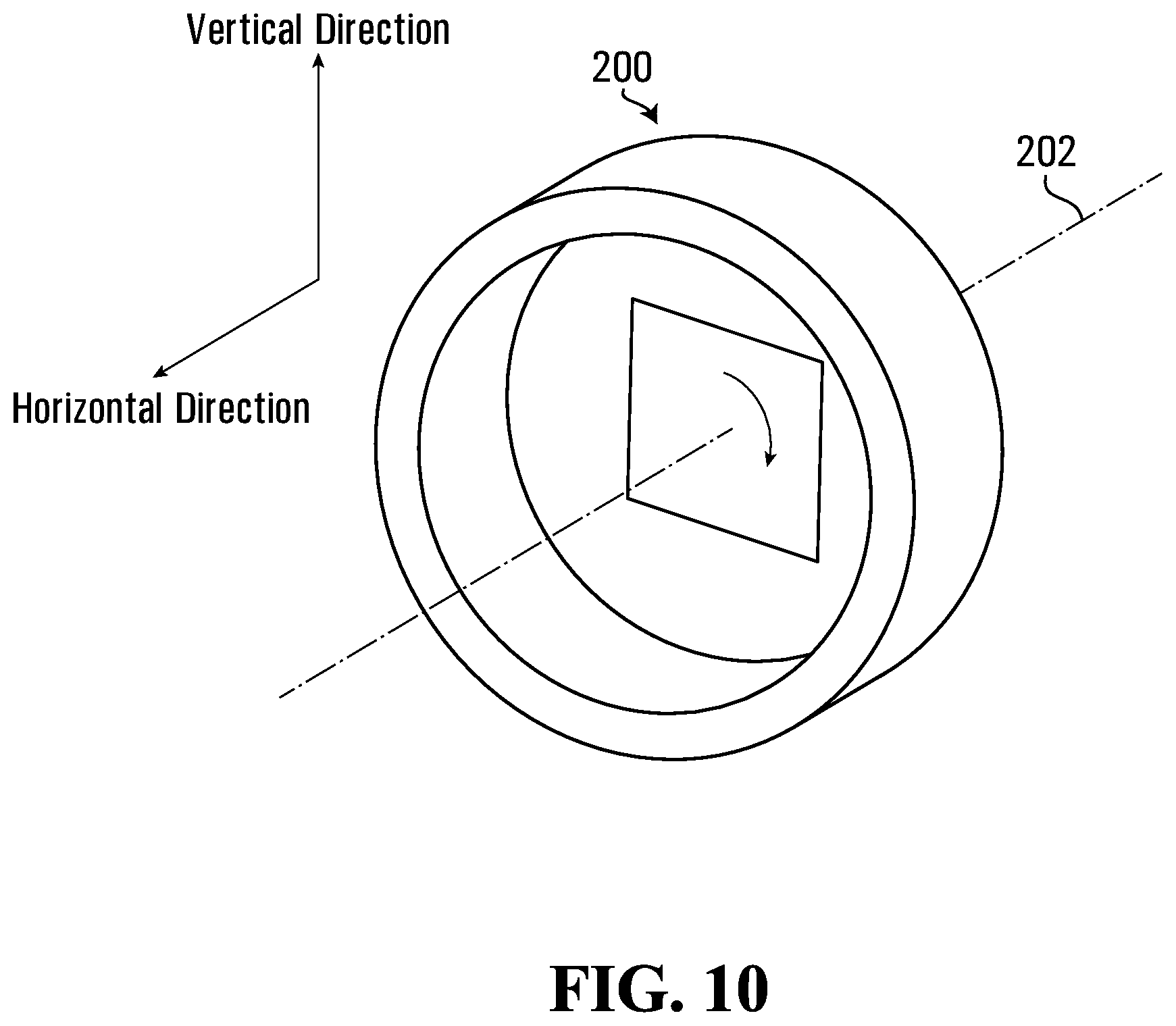
FIG. 10 shows an example of a spin casting process that may be used to make the non-pneumatic tire;
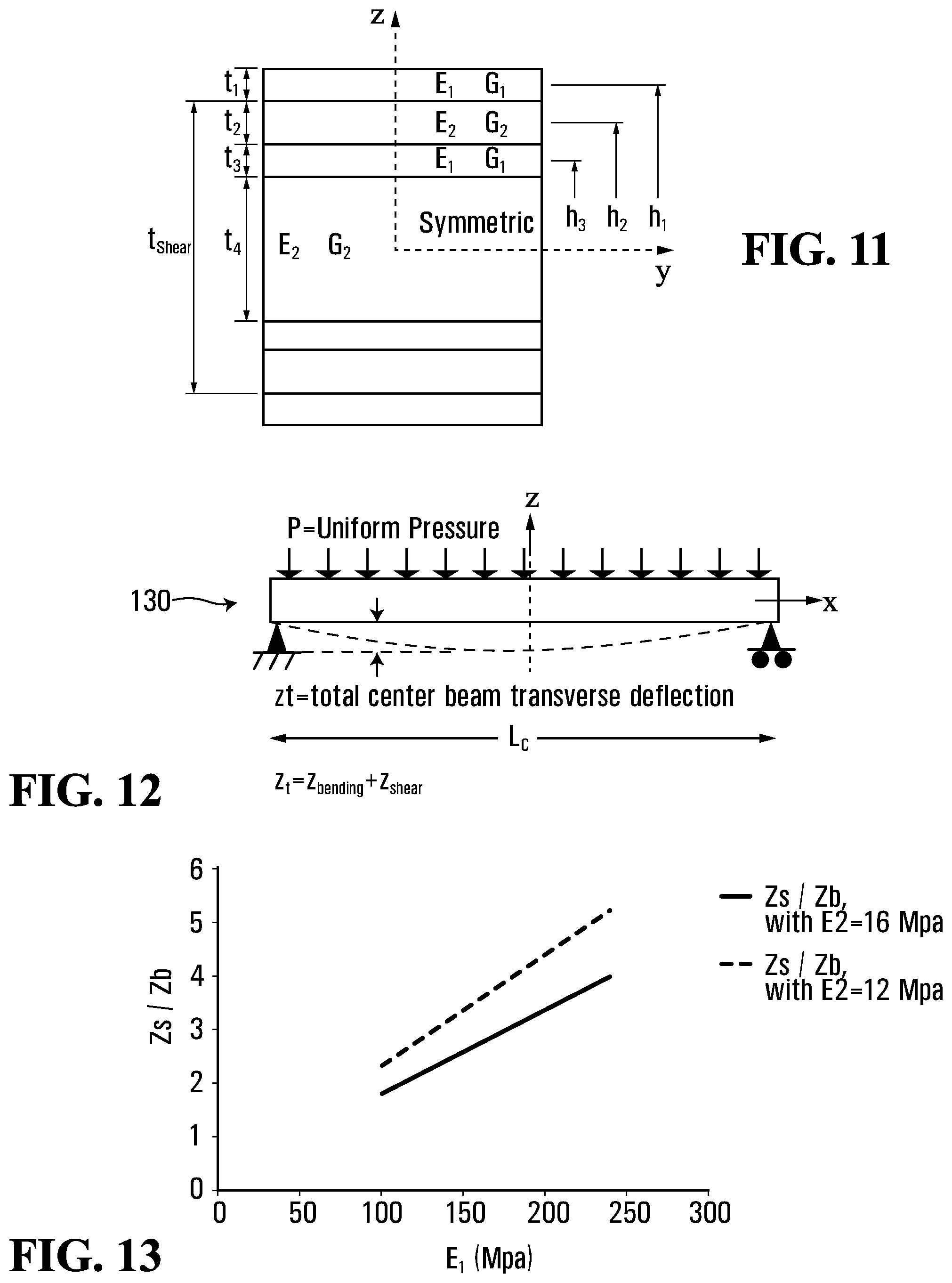
FIG. 11 shows a cross section view of an example of a straight beam that comprises a laminate configuration of elastomer materials;
FIG. 12 shows a side elevation view of the straight beam of FIG. 11 when simply supported by two parallel contact surfaces and subjected to a constant pressure P;
FIG. 13 shows a graph showing an example of a relationship between a ratio of beam deflections due to shear and due to bending and a modulus of elasticity of an elastomeric material;
FIG. 14 shows a finite-element model of an embodiment of the annular beam loaded between two parallel contact surfaces;
FIG. 15 shows analytical solutions of a contact pressure distribution along a contact length of a contact patch of an embodiment of the annular beam comprising the laminate configuration and an embodiment of an annular beam made of an isotropic elastomer;
FIG. 16 shows a finite-element model of an embodiment of the non-pneumatic tire comprising the annular beam of FIG. 14 and subjected to a vertical load on a rigid contact surface;
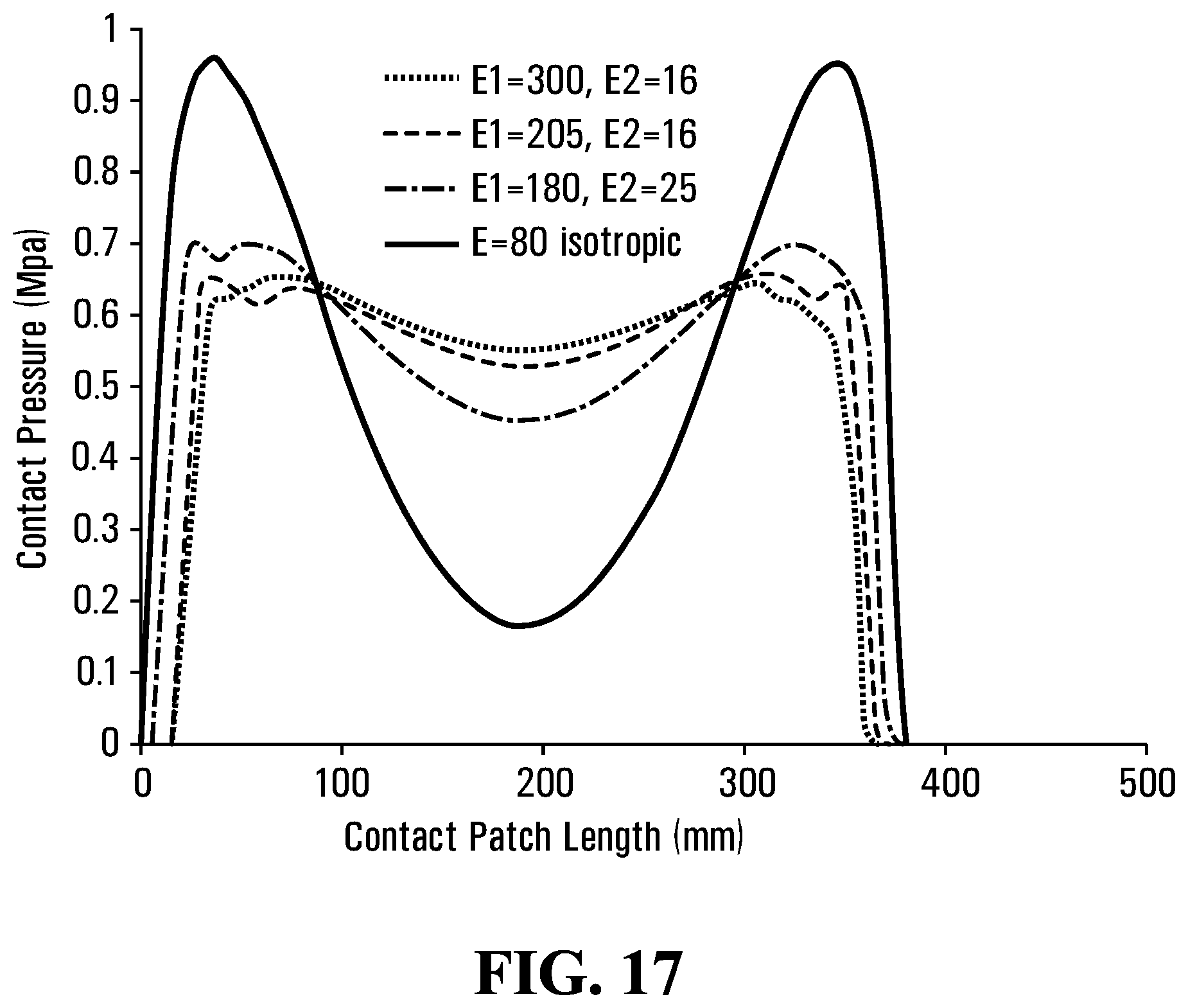
FIG. 17 shows analytical solutions of a contact pressure distribution along the contact length of the contact patch of an embodiment of the annular beam of the non-pneumatic tire of FIG. 16 comprising different laminate configurations and an embodiment of an annular beam comprising an isotropic elastomer;
FIG. 18 shows an example of a thermoplastic polyurethane exhibiting non-linear stress vs. strain characteristics;
FIG. 19 shows a perspective view of the wheel comprising the non-pneumatic tire in accordance with another embodiment of the invention;
FIG. 20 shows a finite-element model of the non-pneumatic tire of FIG. 19 subjected to a vertical load on a deformable contact surface;
FIG. 21 shows analytical solutions of a contact pressure distribution along a contact length of the contact patch of the non-pneumatic tire of FIG. 20;
FIG. 22 shows a finite-element model of the non-pneumatic tire of FIG. 20;
FIG. 23 shows a partial cross-sectional view of the non-pneumatic tire that comprises a tread comprising a reinforcing layer in accordance with another embodiment of the invention;
FIGS. 24 and 25 show an example of another vehicle comprising wheels that comprise non-pneumatic tires in accordance with another embodiment of the invention; and
FIG. 26 shows an example of another vehicle comprising wheels that comprises non-pneumatic tires in accordance with another embodiment of the invention.
DETAILED DESCRIPTION OF EMBODIMENTS
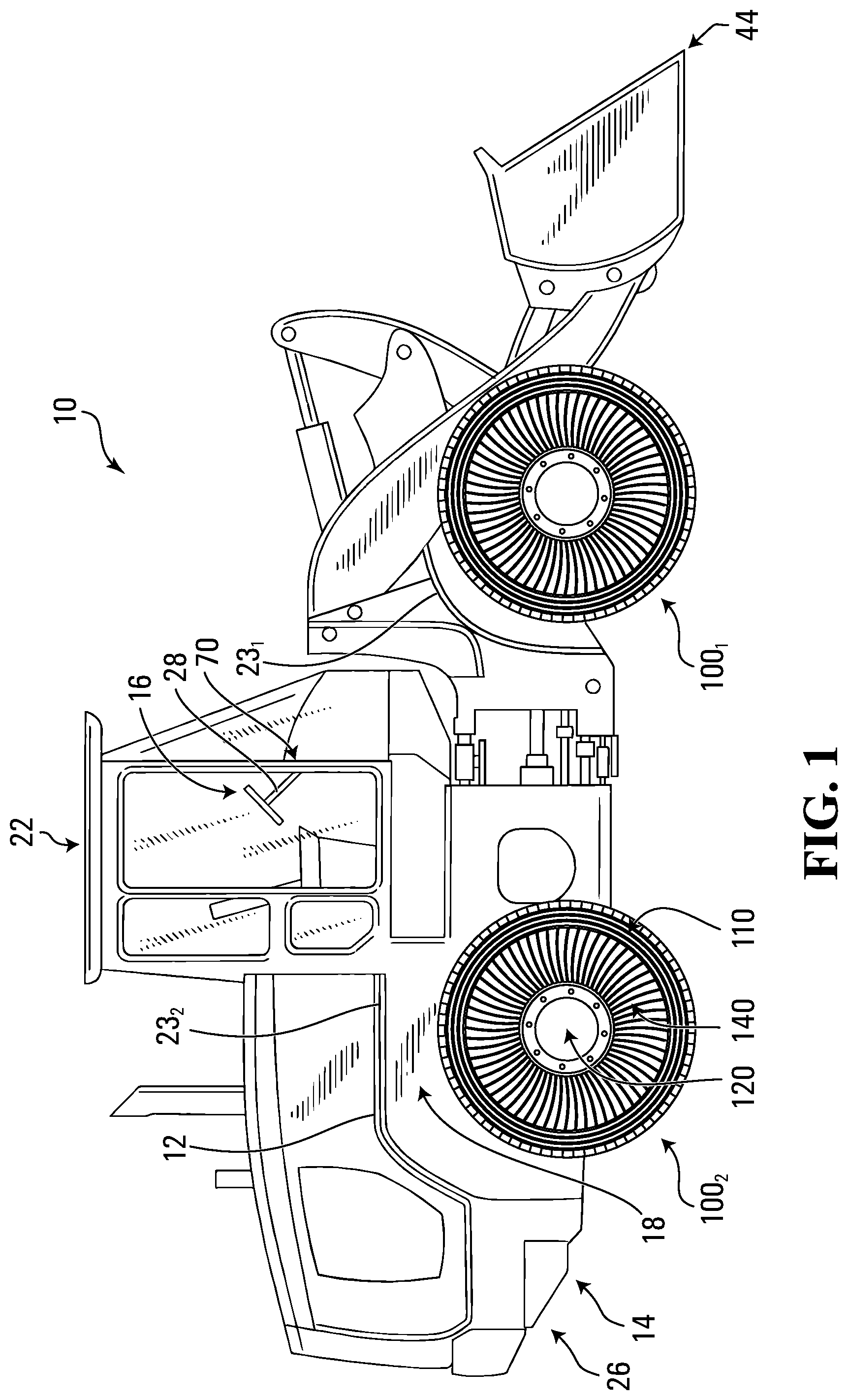
FIG. 1 shows an example of a vehicle 10 comprising a plurality of wheels 100.sub.1-100.sub.4 in accordance with an embodiment of the invention. In this embodiment, the vehicle 10 is an industrial vehicle. The industrial vehicle 10 is a heavy-duty vehicle designed to travel off-road to perform industrial work using a work implement 44. In this embodiment, the industrial vehicle 10 is a construction vehicle for performing construction work using the work implement 44. More particularly, in this embodiment, the construction vehicle 10 is a loader (e.g., a skid-steer loader). The construction vehicle 10 may be a bulldozer, a backhoe loader, an excavator, a dump truck, or any other type of construction vehicle in other embodiments. In this example, the construction vehicle 10 comprises a frame 12, a powertrain 14, a steering system 16, a suspension 18, the wheels 100.sub.1-100.sub.4, and an operator cabin 22, which enable a user, i.e., an operator, of the construction vehicle 10 to move the vehicle 10 on the ground and perform work using the work implement 44. The construction vehicle 10 has a longitudinal direction, a widthwise direction, and a height direction.
In this embodiment, as further discussed later, the wheels 100.sub.1-100.sub.4 are non-pneumatic (i.e., airless) and may be designed to enhance their use and performance and/or use and performance of the construction vehicle 10, including, for example, by having a high load-carrying capacity while being relatively lightweight.
The powertrain 14 is configured for generating motive power and transmitting motive power to respective ones of the wheels 100.sub.1-100.sub.4 to propel the construction vehicle 10 on the ground. To that end, the powertrain 14 comprises a prime mover 26, which is a source of motive power that comprises one or more motors. For example, in this embodiment, the prime mover 26 comprises an internal combustion engine. In other embodiments, the prime mover 26 may comprise another type of motor (e.g., an electric motor) or a combination of different types of motor (e.g., an internal combustion engine and an electric motor). The prime mover 26 is in a driving relationship with one or more of the wheels 100.sub.1-100.sub.4. That is, the powertrain 14 transmits motive power generated by the prime mover 26 to one or more of the wheels 100.sub.1-100.sub.4 (e.g., via a transmission and/or a differential) in order to drive (i.e., impart motion to) these one or more of the wheels 100.sub.1-100.sub.4.
The steering system 16 is configured to enable the operator to steer the construction vehicle 10 on the ground. To that end, the steering system 16 comprises a steering device 28 that is operable by the operator to direct the construction vehicle 10 along a desired course on the ground. The steering device 28 may comprise a steering wheel or any other steering component (e.g., a joystick) that can be operated by the operator to steer the construction vehicle 10. The steering system 16 responds to the operator interacting with the steering device 28 by turning respective ones of the wheels 100.sub.1-100.sub.4 to change their orientation relative to part of the frame 12 of the construction vehicle 10 in order to cause the vehicle 10 to move in a desired direction. In this example, a front frame member 23.sub.1 carrying front ones of the wheels 100.sub.1-100.sub.4 is turnable in response to input of the operator at the steering device 28 to change its orientation and thus the orientation of the front ones of the wheels 100.sub.1-100.sub.4 relative to a rear frame member 23.sub.2 of the construction vehicle 10 in order to steer the construction vehicle 10 on the ground.
The suspension 18 is connected between the frame 12 and the wheels 100.sub.1-100.sub.4 to allow relative motion between the frame 12 and the wheels 100.sub.1-100.sub.4 as the construction vehicle 10 travels on the ground. For example, the suspension 18 may enhance handling of the construction vehicle 10 on the ground by absorbing shocks and helping to maintain traction between the wheels 100.sub.1-100.sub.4 and the ground. The suspension 18 may comprise an arrangement of springs and dampers. A spring may be a coil spring, a leaf spring, a gas spring (e.g., an air spring), or any other elastic object used to store mechanical energy. A damper (also sometimes referred to as a "shock absorber") may be a fluidic damper (e.g., a pneumatic damper, a hydraulic damper, etc.), a magnetic damper, or any other object which absorbs or dissipates kinetic energy to decrease oscillations. In some cases, a single device may itself constitute both a spring and a damper (e.g., a hydropneumatic, hydrolastic, or hydragas suspension device).
The operator cabin 22 is where the operator sits and controls the construction vehicle 10. More particularly, the operator cabin 22 comprises a user interface 70 including a set of controls that allow the operator to steer the construction vehicle 10 on the ground and operate the work implement 44. The user interface 70 also comprises an instrument panel (e.g., a dashboard) which provides indicators (e.g., a speedometer indicator, a tachometer indicator, etc.) to convey information to the operator.
The wheels 100.sub.1-100.sub.4 engage the ground to provide traction to the construction vehicle 10. More particularly, in this example, the front ones of the wheels 100.sub.1-100.sub.4 provide front traction to the construction vehicle 10 while the rear ones of the wheels 100.sub.1-100.sub.4 provide rear traction to the construction vehicle 10.
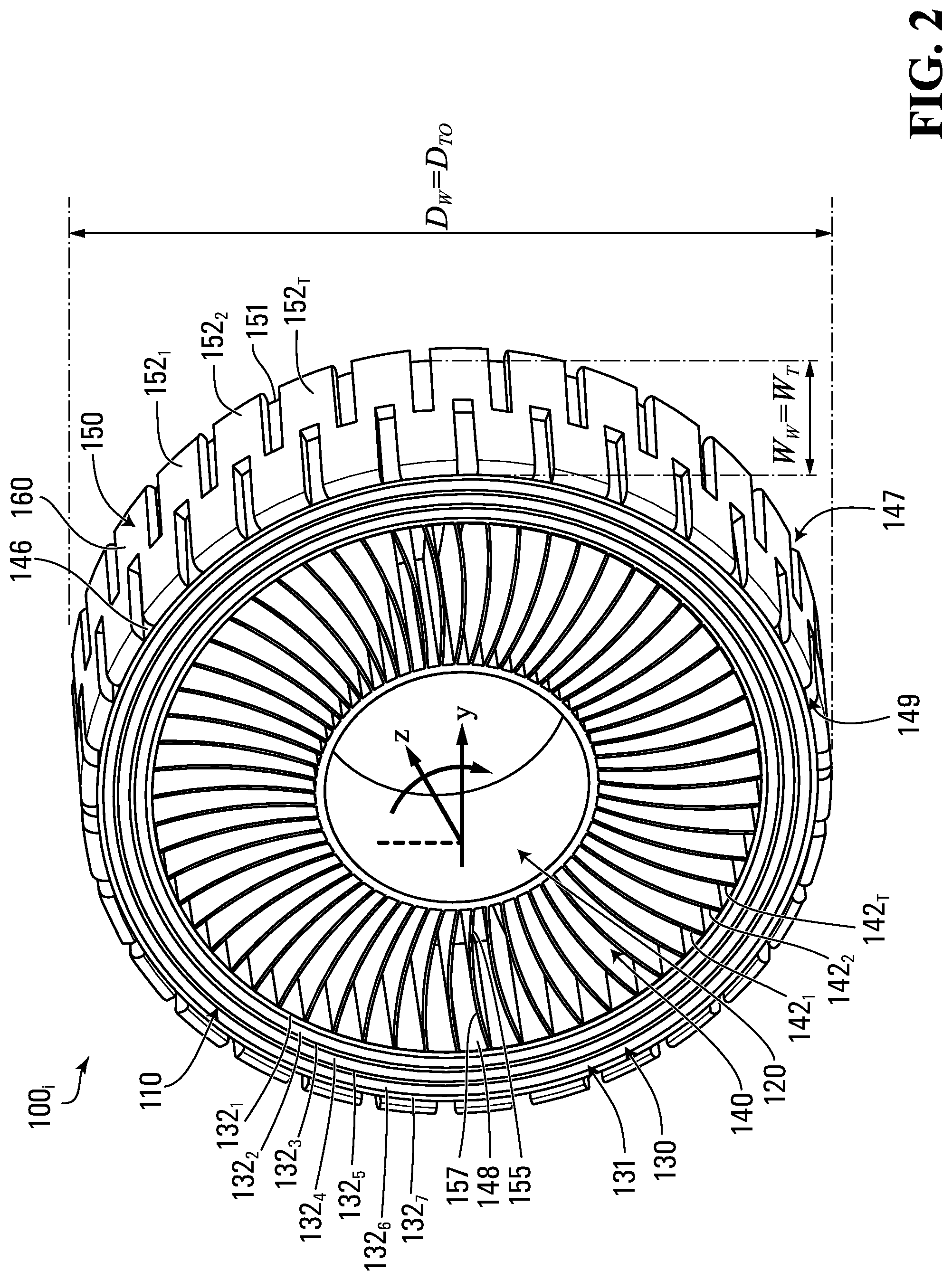
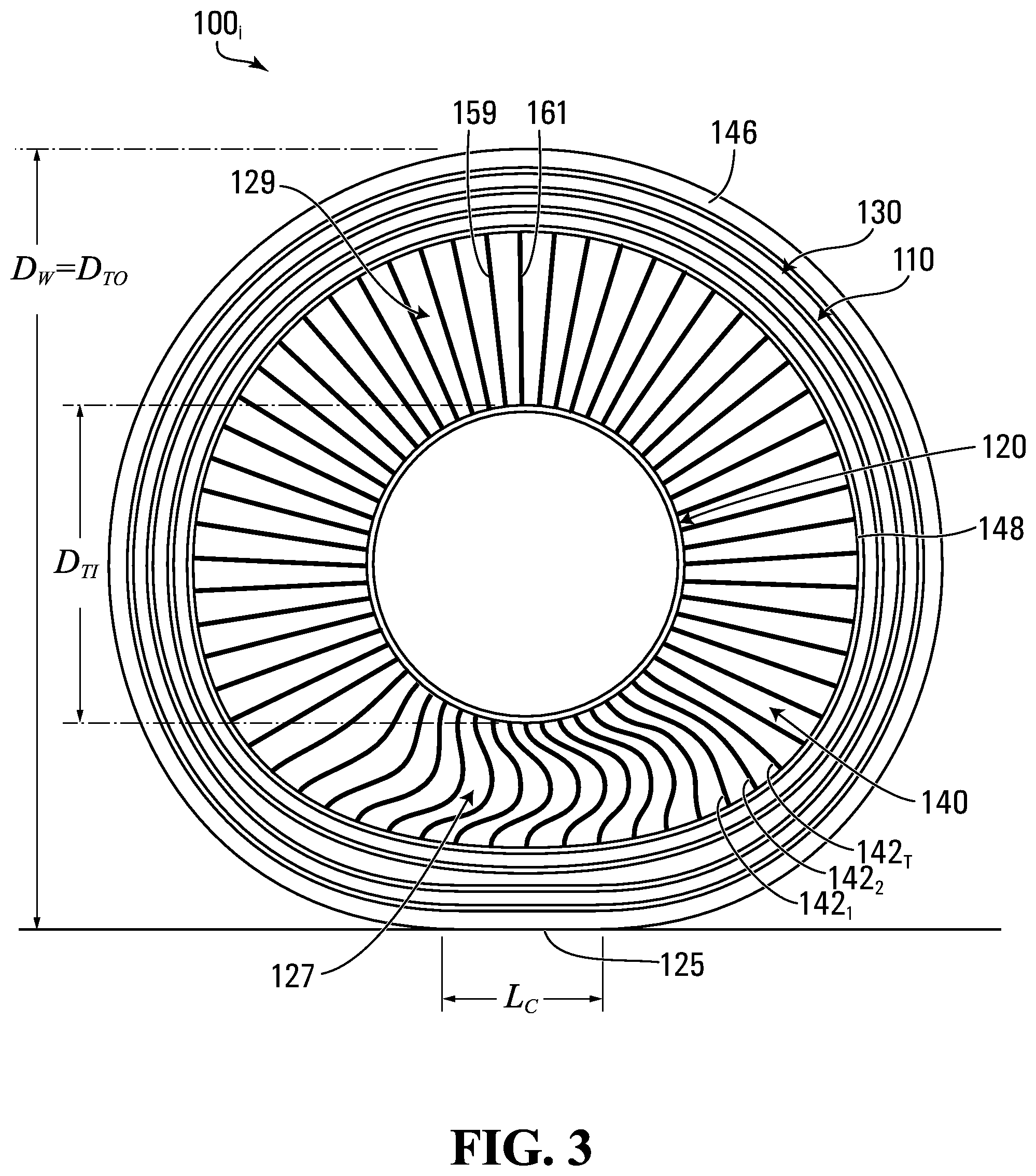
Each wheel 100.sub.i comprises a non-pneumatic tire 110 for contacting the ground and a hub 120 for connecting the wheel 100.sub.i to an axle of the vehicle 10. The non-pneumatic tire 110 is a compliant wheel structure that is not supported by gas (e.g., air) pressure and that is resiliently deformable (i.e., changeable in configuration) as the wheel 100.sub.i contacts the ground. With additional reference to FIG. 2, the wheel 100.sub.i has an axial direction defined by an axis of rotation 180 of the wheel 100.sub.i (also referred to as a "Y" direction), a radial direction (also referred to as a "Z" direction), and a circumferential direction (also referred to as a "X" direction). These axial, radial and circumferential directions also apply to components of the wheel 100.sub.i, including the non-pneumatic tire 110. The wheel's equatorial plane is that plane defined by the x-z axes, while the wheel's cross section is that plane defined by the y-z axes. The wheel 100.sub.i has an outer diameter D.sub.W and a width W.sub.W. It comprises an inboard lateral side 147 for facing a center of the vehicle in the widthwise direction of the vehicle and an outboard lateral side 149 opposite the inboard lateral side 147. As shown in FIG. 3, when it is in contact with the ground, the wheel 100.sub.i has an area of contact 125 with the ground, which may be referred to as a "contact patch" of the wheel 100.sub.i with the ground. The contact patch 125 of the wheel 100.sub.i, which is a contact interface between the non-pneumatic tire 110 and the ground, has a length L.sub.C in the circumferential direction of the wheel 100.sub.i and a width W.sub.C in the axial direction of the wheel 100.sub.i.
The non-pneumatic tire 110 comprises an annular beam 130 and an annular support 140 that is disposed between the annular beam 130 and the hub 120 of the wheel 100.sub.i and configured to support loading on the wheel 100.sub.i as the wheel 100.sub.i engages the ground. In this embodiment, the non-pneumatic tire 110 is tension-based such that the annular support 140 is configured to support the loading on the wheel 100.sub.i by tension. That is, under the loading on the wheel 100.sub.i, the annular support 140 is resiliently deformable such that a lower portion 127 of the annular support 140 between the axis of rotation 180 of the wheel 100.sub.i and the contact patch 125 of the wheel 100.sub.i is compressed and an upper portion 129 of the annular support 140 above the axis of rotation 180 of the wheel 100.sub.i is in tension to support the loading.
The annular beam 130 of the non-pneumatic tire 110 is configured to deflect under the loading on the wheel 100.sub.i at the contact patch 125 of the wheel 100.sub.i with the ground. In this embodiment, the annular beam 130 is configured to deflect such that it applies a homogeneous contact pressure along the length L.sub.C of the contact patch 125 of the wheel 100.sub.i with the ground.
More particularly, in this embodiment, the annular beam 130 comprises a shear band 131 configured to deflect predominantly by shearing at the contact patch 125 under the loading on the wheel 100.sub.i. That is, under the loading on the wheel 100.sub.i, the shear band 131 deflects significantly more by shearing than by bending at the contact patch 125. The shear band 131 is thus configured such that, at a center of the contact patch 125 of the wheel 100.sub.i in the circumferential direction of the wheel 100.sub.i, a shear deflection of the annular beam 130 is significantly greater than a bending deflection of the annular beam 130. For example, in some embodiments, at the center of the contact patch 125 of the wheel 100.sub.i in the circumferential direction of the wheel 100.sub.i, a ratio of the shear deflection of the annular beam 130 over the bending deflection of the annular beam 130 may be at least 1.2, in some cases at least 1.5, in some cases at least 2, in some cases at least 3, in some cases at least 5, in some cases at least 7, and in some cases even more. For instance, in some embodiments, the annular beam 130 may be designed based on principles discussed in U.S. Patent Application Publication 2014/0367007, which is hereby incorporated by reference herein, in order to achieve the homogeneous contact pressure along the length L.sub.C of the contact patch 125 of the wheel 100.sub.i with the ground.
In this embodiment, the shear band 131 of the annular beam 130 comprises a plurality of layers 132.sub.1-132.sub.N of different elastomeric materials M.sub.1-M.sub.E. The layers 132.sub.1-132.sub.N of the different elastomeric materials M.sub.1-M.sub.E extend in the circumferential direction of the wheel 100.sub.i and are disposed relative to one another in the radial direction of the wheel 100.sub.i. As further discussed later, in some embodiments, this laminate construction of the different elastomeric materials M.sub.1-M.sub.E may enhance performance of the wheel 100.sub.i, including behavior of its contact patch 125 and may also help the annular beam 130 to have a high load to mass ratio, yet keep the simplicity of an elastomer structure, with no need for inextensible membranes or other composites or reinforcing elements. In this example, the layers 132.sub.1-132.sub.N of the different elastomeric materials M.sub.1-M.sub.E are seven layers, namely the layers 132.sub.1-132.sub.7 and the different elastomeric materials M.sub.1-M.sub.E are two different elastomeric materials, namely the elastomeric materials M.sub.1, M.sub.2. The layers 132.sub.1-132.sub.N and/or the elastomeric materials M.sub.1-M.sub.E may be present in any other suitable numbers in other examples.
More particularly, in this embodiment, the layers 132.sub.1, 132.sub.3, 132.sub.5 and 132.sub.7 are made of the elastomeric material M.sub.1 while the layers 132.sub.2, 132.sub.4 and 132.sub.6 are made of the elastomeric material M.sub.2 and are disposed between respective ones of the layers 132.sub.1, 132.sub.3, 132.sub.5 and 132.sub.7 made of the elastomeric material M.sub.1. The layers 132.sub.1-132.sub.7 of the annular beam 130 are thus arranged such that the different elastomeric materials M1, M2 alternate in the radial direction of the wheel 100.sub.i.
For instance, in this embodiment, the shear band 131 comprises the layer 132.sub.1, composed of elastomeric material M.sub.1, lying on a radially inward extent of the shear band 131. The shear band 131 comprises the layer 132.sub.2, composed of elastomeric material M.sub.2, lying on a radially outward extent of the layer 132.sub.1. The shear band 131 comprises the layer 132.sub.3, composed of elastomeric material M.sub.1, lying on a radially outward extent of the layer 132.sub.2. In this embodiment, a laminate configuration of the elastomeric material of the shear band 131 is M.sub.1/M.sub.2/M.sub.1. In other embodiments, the laminate configuration of the elastomeric material of the shear band 131 may be repeated any number of times. For example, in FIGS. 4 and 5, the laminate configuration of the elastomeric material of the shear band 131 from an inward to an outward extent of the shear band 131 is M.sub.1/M.sub.2/M.sub.1/M.sub.2/M.sub.1/M.sub.2/M.sub.1. Each one of the layers 132.sub.1-132.sub.7 is composed of a homogeneous elastomer in this example.
The different elastomeric materials M.sub.1 and M.sub.2 may differ in any suitable way. For example, in some embodiments, a stiffness of the elastomeric material M.sub.1 may be different from a stiffness of the elastomeric material M.sub.2. That is, the elastomeric material M.sub.1 may be stiffer or less stiff than the elastomeric material M.sub.2. For instance, a modulus of elasticity E.sub.1 (i.e., Young's modulus) of the elastomeric material M.sub.1 may be different from a modulus of elasticity E.sub.2 of the elastomeric material M.sub.2. A modulus of elasticity herein is Young's tensile modulus of elasticity measured per ISO 527-1/-2, and "Young's Modulus," "tensile modulus," and "modulus" may be used interchangeably herein. For example, in some embodiments, the modulus of elasticity E.sub.1 of the elastomeric material M.sub.1 may be greater than the modulus of elasticity E.sub.2 of the elastomeric material M.sub.2. For instance, in some embodiments, a ratio E.sub.1/E.sub.2 of the modulus of elasticity E.sub.1 of the elastomeric material M.sub.1 over the modulus of elasticity E.sub.2 of the elastomeric material M.sub.2 may be at least 2, in some cases at least 3, in some cases at least 4, in some cases at least 5, in some cases at least 6, in some cases at least 7, in some cases at least 8, and in some cases even more.
For example, in some embodiments, the modulus of elasticity E.sub.1 of the elastomeric material M.sub.1 may be at least 150 MPa, and in some cases at least 200 MPa or even more, while the modulus of elasticity E.sub.2 of the elastomeric material M.sub.2 may be no more than 50 MPa, and in some cases no more than 30 MPa or even less. As will be disclosed, such a modulus definition can be engineered to give a beam particular bending and shear properties that are favorable for use in the non-pneumatic tire 110.
FIG. 5 shows a cross section AA of the shear band 131 of the annular beam 130 where the layers 132.sub.1-132.sub.7 of the annular beam 131 are shown. In some embodiments, such as the embodiment of FIGS. 4 and 5, the innermost layer 132.sub.1 and the outermost layer 132.sub.7 of the shear band 131 may be composed of the elastomeric material M.sub.1 with the modulus of elasticity E.sub.1 higher than the modulus of elasticity E.sub.2 of the elastomeric material M.sub.2. That is, in this embodiment, the elastomeric material with the higher modulus of elasticity may be used at the inner and outer radial extents of the shear band 131 of the annular beam 130.
In other embodiments, other repeating or non-repeating laminate configurations of the elastomeric material of the shear band 131 comprising the elastomeric material with the higher modulus of elasticity at the inner and outer radial extents of the shear band 131 may be used. That is, in these embodiments, multiple layers composed of multiple elastomeric materials may be used with or without symmetry of the laminate configuration of the elastomeric material of the shear band 131 and the shear band 131 may comprise at least three elastomeric materials in a laminate configuration. For example, the laminate configuration of the elastomeric material of the shear band 131 from an inward to an outward extent of the shear band 131 may be of the type M.sub.1/M.sub.2/M.sub.3/M.sub.2/M.sub.1 or M.sub.1/M.sub.2/M.sub.3/M.sub.1 or any other combination thereof, where M.sub.3 is an elastomeric material having a modulus of elasticity E.sub.3 different from the modulus of elasticity E.sub.1 of the elastomeric material M.sub.1 and different from the modulus of elasticity E.sub.2 of the elastomeric material M.sub.2.
In some embodiments, and with further reference to FIGS. 4 and 5, each one of the layers 132.sub.1-132.sub.7 of the shear band 131 extends from the inboard lateral side 147 to the outboard lateral side 149 of the non-pneumatic tire 110. That is, each one of the layers 132.sub.1-132.sub.7 of the shear band 131 extends laterally through the shear band 131 in the axial direction of the wheel 100.
The different elastomeric materials M.sub.1-M.sub.E may include any other suitable elastomers in various embodiments. For example, in some embodiments, suitable elastomeric materials include thermoplastic and thermoset polyurethane and thermoplastic and thermoset rubbers.
In this embodiment, the annular beam 130 is free of (i.e., without) a substantially inextensible reinforcing layer running in the circumferential direction of the wheel 100.sub.i (e.g., a layer of metal, composite (e.g., carbon fibers, other fibers), and/or another material that is substantially inextensible running in the circumferential direction of the wheel 100.sub.i). In that sense, the annular beam 130 may be said to be "unreinforced". Thus, in this embodiment, useful behavior of the wheel 100.sub.i, including deflection and behavior of its contact patch 125, may be achieved without any substantially inextensible reinforcing layer running in the circumferential direction of the wheel 100.sub.i, which may help to reduce the weight and cost of the wheel 100.sub.i.
In this embodiment, the non-pneumatic tire 110 comprises a tread 150 for enhancing traction between the non-pneumatic tire 110 and the ground. The tread 150 is disposed about an outer peripheral extent 146 of the annular beam 130, in this case about the outermost layer 132.sub.7 of the shear band 131 composed of the elastomeric material M.sub.1. More particularly, in this example the tread 150 comprises a tread base 151 that is at the outer peripheral extent 146 of the annular beam 130 and a plurality of tread projections 152.sub.1-152.sub.T that project from the tread base 151. The tread 150 may be implemented in any other suitable way in other embodiments (e.g., may comprise a plurality of tread recesses, etc.).
The annular support 140 is configured to support the loading on the wheel 100.sub.i as the wheel 100.sub.i engages the ground. As mentioned above, in this embodiment, the annular support 140 is configured to support the loading on the wheel 100.sub.i by tension. More particularly, in this embodiment, the annular support 140 comprises a plurality of support members 142.sub.1-142.sub.T that are distributed around the non-pneumatic tire 110 and resiliently deformable such that, under the loading on the wheel 100.sub.i, lower ones of the support members 142.sub.1-142.sub.T in the lower portion 127 of the annular support 140 (between the axis of rotation 180 of the wheel 100.sub.i and the contact patch 125 of the wheel 100.sub.i) are compressed and bend while upper ones of the support members 142.sub.1-142.sub.T in the upper portion 129 of the annular support 140 (above the axis of rotation 180 of the wheel 100.sub.i) are tensioned to support the loading. As they support load by tension when in the upper portion 129 of the annular support 140, the support members 142.sub.1-142.sub.T may be referred to as "tensile" members.
In this embodiment, the support members 142.sub.1-142.sub.T are elongated and extend from the annular beam 130 towards the hub 120 generally in the radial direction of the wheel 100.sub.i. In that sense, the support members 142.sub.1-142.sub.T may be referred to as "spokes" and the annular support 140 may be referred to as a "spoked" support.
More particularly, in this embodiment, each spoke 142.sub.i extends from an inner peripheral surface 148 of the annular beam 130 towards the hub 120 generally in the radial direction of the wheel 100.sub.i and from a first lateral end 155 to a second lateral end 157 in the axial direction of the wheel 100.sub.i. In this case, the spoke 142.sub.i extends in the axial direction of the wheel 100.sub.i for at least a majority of a width W.sub.T of the non-pneumatic tire 110, which in this case corresponds to the width W.sub.W of the wheel 100.sub.i. For instance, in some embodiments, the spoke 142.sub.i may extend in the axial direction of the wheel 100.sub.i for more than half, in some cases at least 60%, in some cases at least 80%, and in some cases an entirety of the width W.sub.T of the non-pneumatic tire 110. Moreover, the spoke 142.sub.i has a thickness T.sub.S measured between a first surface face 159 and a second surface face 161 of the spoke 142.sub.i that is significantly less than a length and width of the spoke 142.sub.i.
When the wheel 100.sub.i is in contact with the ground and bears a load (e.g., part of a weight of the vehicle), respective ones of the spokes 142.sub.1-142.sub.T that are disposed in the upper portion 129 of the spoked support 140 (i.e., above the axis of rotation 180 of the wheel 100.sub.i) are placed in tension while respective ones of the spokes 142.sub.1-142.sub.T that are disposed in the lower portion 127 of the spoked support 140 (i.e., adjacent the contact patch 125) are placed in compression. The spokes 142.sub.1-142.sub.T in the lower portion 127 of the spoked support 140 which are in compression bend in response to the load. Conversely, the spokes 142.sub.1-142.sub.T in the upper portion 129 of the spoked support 140 which are placed in tension support the load by tension.
The spokes 142.sub.1-142.sub.T may be implemented in any other suitable way in other embodiments. For example, FIGS. 6 to 9 show various embodiments of the design of the spokes 142.sub.1-142.sub.T. In the embodiment of FIG. 6, each spoke 142.sub.i extends generally along a straight line in the radial direction of the wheel 100.sub.i. In the embodiment of FIG. 7, each spoke 142.sub.i extends generally along a straight line in the radial direction of the wheel 100.sub.i, a spoke connector 143 being located between every other pair of successive spokes 142.sub.i and connecting two successive spokes 142.sub.i. The spoke connector 143 is substantially perpendicular to the radial direction of the wheel 100.sub.i and may be positioned at any distance from the hub 120. along the radial direction of the wheel 100.sub.i. In some embodiment, the spoke connector 143 extends in the axial direction of the wheel 100.sub.i for at least a majority of the width W.sub.T of the non-pneumatic tire 110, which in this case corresponds to the width W.sub.W of the wheel 100.sub.i. For instance, in some embodiments, the spoke connector 143 may extend in the axial direction of the wheel 100.sub.i for more than half, in some cases at least 60%, in some cases at least 80%, and in some cases an entirety of the width W.sub.T of the non-pneumatic tire 110. Moreover, the spoke connector 143 has a thickness T.sub.SC measured between a first surface face 163 and a second surface face 165 of the spoke connector 143 that is significantly less than a length and width of the spoke connector 143. In other embodiments, the spoke connector 143 may not be substantially perpendicular to the radial direction of the wheel 100.sub.i. In other embodiments, there may be a plurality of spoke connectors 143 connecting two spokes 142.sub.i. In the embodiment of FIG. 8, each spoke 142.sub.i extends generally along a straight line at an angle .alpha. or -.alpha. in the radial direction of the wheel 100.sub.i such that two successive spokes 142.sub.i do not extend generally along a straight line at the same angle in the radial direction of the wheel 100.sub.i. In the embodiment of FIG. 9, each spoke 142.sub.i extends generally as a curved line along the radial direction of the wheel 100.sub.i. Other designs may be possible in other embodiments.
The non-pneumatic tire 110 has an inner diameter D.sub.TI and an outer diameter D.sub.TO, which in this case corresponds to the outer diameter D.sub.W of the wheel 100. A sectional height H.sub.T of the non-pneumatic tire 110 is half of a difference between the outer diameter D.sub.TO and the inner diameter D.sub.TI of the non-pneumatic tire 110. The sectional height HT of the non-pneumatic tire may be significant in relation to the width W.sub.T of the non-pneumatic tire 110. In other words, an aspect ratio AR of the non-pneumatic tire 110 corresponding to the sectional height H.sub.T over the width W.sub.T of the non-pneumatic tire 110 may be relatively high. For instance, in some embodiments, the aspect ratio AR of the non-pneumatic tire 110 may be at least 70%, in some cases at least 90%, in some cases at least 110%, and in some cases even more. Also, the inner diameter D.sub.TI of the non-pneumatic tire 110 may be significantly less than the outer diameter D.sub.TO of the non-pneumatic tire 110 as this may help for compliance of the wheel 100.sub.i. For example, in some embodiments, the inner diameter D.sub.TI of the non-pneumatic tire 110 may be no more than half of the outer diameter D.sub.TO of the non-pneumatic tire 110, in some cases less than half of the outer diameter D.sub.TO of the non-pneumatic tire 110, in some cases no more than 40% of the outer diameter D.sub.TO of the non-pneumatic tire 110, and in some cases even a smaller fraction of the outer diameter D.sub.TO of the non-pneumatic tire 110.
In this embodiment, the non-pneumatic tire 110 therefore comprises different tire materials that make up the tire 110, including the elastomeric materials M.sub.1-M.sub.E of the shear band 131 of the annular beam 130 and a spoke material 145 that makes up at least a substantial part (i.e., a substantial part or an entirety) of the spokes 142.sub.1-142.sub.T. The hub 120 comprises a hub material 172 that makes up at least a substantial part of the hub 120. In some embodiments, the hub material 172 may be the same as one of the tire materials, namely one of the elastomeric materials M.sub.1-M.sub.E of the shear band 131 of the annular beam 130 and the spoke material 145. In other embodiments, the hub material 172 may be different from any of the tire materials, i.e., different from any of the elastomeric materials M.sub.1-M.sub.E of the shear band 131 of the annular beam 130 and the spoke material 145. For instance, in some embodiments, the spoke material 145 and the hub material 172 may be any one of the elastomeric material M.sub.1, M.sub.2, M.sub.3 or any other elastomeric material that may be comprised in the shear band 131 of the annular beam 130.
In this embodiment, any given material of the wheel 100.sub.i, such as any given one of the tire materials (i.e., the elastomeric materials M.sub.1-M.sub.E of the shear band 131 of the annular beam 130 and the spoke material 145) and/or the hub material 172 may exhibit a non-linear stress vs. strain behavior. For instance, the spoke material 145 may have a secant modulus that decreases with increasing strain of the spoke material 145. A secant modulus herein is defined as a tensile stress divided by a tensile strain for any given point on a tensile stress vs. tensile strain curve measured per ISO 527-1/-2. The spoke material 145 may have a high Young's modulus that is significantly greater than the secant modulus at 100% strain (a.k.a. "the 100% modulus"). Such a non-linear behavior of the spoke material 145 may provide efficient load carrying during normal operation and enable impact loading and large local deflections without generating high stresses. For instance, the spoke material 145 may allow the non-pneumatic tire 110 to operate at a low strain rate (e.g., 2% to 5%) during normal operation yet simultaneously allow large strains (e.g., when the wheel 100.sub.i engages obstacles) without generating high stresses. This in turn may be helpful to minimize vehicle shock loading and enhance durability of the non-pneumatic tire 110.
The non-pneumatic tire 110 may comprise any other arrangement of materials in other embodiments (e.g., different parts of the annular beam 130, different parts of the tread 150, and/or different parts of the spokes 142.sub.1-142.sub.T may be made of different materials). For example, in some embodiments, different parts of the tread 150, and/or different parts of the spokes 142.sub.1-142.sub.T may be made of different elastomers.
In this embodiment, the hub material 172 constitutes at least part of the hub 120. More particularly, in this embodiment, the hub material 172 constitutes at least a majority (e.g., a majority or an entirety) of the hub 120. In this example of implementation, the hub material 172 makes up an entirety of the hub 120.
In this example of implementation, the hub material 172 is polymeric. More particularly, in this example of implementation, the hub material 172 is elastomeric. For example, in this embodiment, the hub material 172 comprises a polyurethane (PU) elastomer. For instance, in some cases, the PU elastomer may be PET-95A commercially available from COIM, cured with MCDEA.
The hub material 172 may be any other suitable material in other embodiments. For example, in other embodiments, the hub material 172 may comprise a stiffer polyurethane material, such as COIM's PET75D cured with MOCA. In some embodiments, the hub material 172 may not be polymeric. For instance, in some embodiments, the hub material 172 may be metallic (e.g., steel, aluminum, etc.).
The hub 120 may comprise one or more additional materials in addition to the hub material 172 in other embodiments (e.g., different parts of the hub 120 may be made of different materials).
For example, in some embodiments, for the spoked support 140 and the hub 120, various cast polyurethanes of either ether or ester systems may be used when appropriate (e.g. with alternative cure systems such as MOCA). In some examples, a shore hardness in the range of 90 A to 75 D and/or a Young's modulus between 40 MPA to 2000 MPa may be appropriate.
In some embodiments, the spoked support 140 and the hub 120 may comprise different materials. For example, the spoked support 140 may comprise a softer material (e.g., with a Young's modulus between 40 MPA to 100 MPA) and the hub 120 may comprise a harder material (e.g., with modulus between 300 to 2000 MPA).
The tread 150 may comprise an elastomeric material 160. In some examples of implementation, the elastomeric material 160 of the tread 150 may be different from the elastomeric materials M.sub.1-M.sub.E of the annular beam 130. For example, in some embodiments, the elastomeric material 160 of the tread 150 may be rubber. In other embodiments, the elastomeric material 160 of the tread 150 may be polyurethane or another elastomer. For instance, in some embodiments, the tread 150 may comprise rubber, cast polyurethane or any other suitable elastomer, and may have a Shore hardness of between 60 A to 85 A, with a Young's modulus between 3 MPa and 20 MPa. The tread 150 may be provided in any suitable way, such as by molding and/or adhesively bonding the elastomeric material 160 of the tread 150 about the annular beam 130.
The wheel 100.sub.i may be manufactured in any suitable way. For example, in some embodiments, the non-pneumatic tire 110 and/or the hub 120 may be manufactured via centrifugal casting, a.k.a. spin casting, which involves pouring one or more materials of the wheel 100.sub.i into a mold 200 that rotates about an axis 202 as shown in FIG. 10. The material(s) is(are) distributed within the mold 200 via a centrifugal force generated by the mold's rotation. In some cases, vertical spin casting, in which the mold's axis of rotation 202 is generally vertical, may be used. In other cases, as shown in FIG. 10, horizontal spin casting, in which the mold's axis of rotation 202 is generally horizontal, may be used. In some embodiments, horizontal spin casting may be useful for casting the layers 132.sub.1-132.sub.N of the different elastomeric materials M.sub.1-M.sub.E of the annular beam 130 in a more controlled manner. The wheel 100 may be manufactured using any other suitable manufacturing processes in other embodiments.
The wheel 100.sub.i may be lightweight. That is, a mass M.sub.W of the wheel 100.sub.i may be relatively small. For example, in some embodiments, a ratio M.sub.normalized of the mass M.sub.W of the wheel 100.sub.i in kilograms over the outer diameter D.sub.W of the wheel 100.sub.i normalized by the width W.sub.W of the wheel 100.sub.i,
##EQU00001## may be no more than 0.00035 kg/mm.sup.2, in some cases no more than 0.00030 kg/mm.sup.2, in some cases no more than 0.00025 kg/mm.sup.2, in some cases no more than 0.00020 kg/mm.sup.2, in some cases no more than 0.00015 kg/mm.sup.2, in some cases no more than 0.00013 kg/mm.sup.2, in some cases no more than 0.00011 kg/mm.sup.2, and in some cases even less (e.g., no more than 0.0001 kg/mm.sup.2).
For instance, in some embodiments, the outer diameter of the wheel 100.sub.i may be 1.5 m, the width of the wheel 100.sub.i may be about 0.5 m, and the mass M.sub.W of the wheel 100 may be about 336 kg. The load capacity of the wheel 100.sub.i may be about 10,000 kg at 15 kph. The wheel 100.sub.i may be a replacement for a 20.5''.times.25'' pneumatic tire.
The wheel 100.sub.i, including the non-pneumatic tire 110 and the hub 120, may thus be designed to enhance its use and performance. Notably, in some embodiments, the structure of the shear band 131 of the annular beam 130 comprising the different elastomeric materials M.sub.1-M.sub.E in a laminate configuration may be related to the deflection properties of the annular beam 130 so as to enhance behavior of the contact patch 125 of the wheel 100.sub.i. When connected to the hub 120 via the spokes 142.sub.1-142.sub.T, the annular beam 130 has a high load to mass ratio, yet keeps the simplicity of an elastomer structure, with no need for inextensible membranes or other composites or reinforcing elements.
For example, in some embodiments, a tire contact pressure may be substantially constant along the length L.sub.C of the contact patch 125. To achieve this, the annular beam 130 having a radius of curvature R may be designed such that it develops a relatively constant pressure along the length L.sub.C of the contact patch 125 when the annular beam 130 is deformed to a flat surface. With reference to FIGS. 11 and 12, this is analogous to designing a straight beam which deforms to a circular arc of radius R when subjected to a constant pressure which is equal to the contact pressure of the annular beam 130 along the length L.sub.C of the contact patch 125. The inventor has found that a homogeneous beam of solid cross section does not behave like this. To create this desired performance, beam bending stiffness and beam shear stiffness can be designed using a laminate of elastomer materials, such that the beam deforms primarily in shear. An example of a method for doing so will now be discussed, using standard nomenclature (e.g. see for example Muvdi, B. B., McNabb, J. W., (1980). Engineering Mechanics of Materials, Macmillan Publishing Co., Inc., New York, N.Y., "Shear and Bending Moment in Beams," pp 23-31, and "Deflections of Beams", pp 266-333, which is hereby incorporated by reference herein).
Without wishing to be bound by any theory, it may be useful to consider certain aspects of the physics of elastomers. The relationship of shear force variation to an applied distributed load on a differential beam element can be expressed as follows:
##EQU00002## Where: V=transverse shear force W=Constant distributed load per unit length x=beam length coordinate
The deflection of the differential beam element due to shear deformation alone can be estimated by combining Equation 1 with other known relationships. Adding relations between shear force, shear stress, shear modulus, and cross-sectional area, Equation 2 can be derived:
.times..times. ##EQU00003## Where: G=beam shear modulus A=effective beam cross sectional area z=transverse beam deflection
Shear modulus means the shear modulus of elasticity and is calculated according to Equation 10 below. For small deflections,
.times..times. ##EQU00004## is equal to the inverse of the deformed beam radius of curvature. Making this substitution and considering a beam of unit depth, one obtains Equation 3:
##EQU00005## Where: G=beam shear modulus R=deformed beam radius of curvature A=effective beam cross sectional area, with unit depth P=Constant distributed pressure, with unit depth
According to equation 3, a straight beam of shear modulus G and effective cross sectional area A, such as the straight beam of FIG. 11, will deform into the shape of an arc of radius R when subjected to homogeneous pressure P, provided shear deflection predominates.
Similarly, the annular beam 130 having radius of curvature R, designed such that shear deformation predominates, will develop a homogeneous contact pressure P along the contact patch 125 having the length L.sub.C when deflected against a flat contact surface.
A constant pressure along the contact patch 125 having the length L.sub.C may be a highly desired performance attribute. It may be particularly useful when embodied in the non-pneumatic tire 110 of FIGS. 1 to 3. With further reference to FIG. 3, when a design load is applied at the hub 120, for instance when the wheel 100.sub.i supports the weight of the vehicle 10, the annular beam 130 deforms over the contact patch 125 having the length L.sub.C and develops a homogeneous contact pressure over the length L.sub.C of the contact patch 125. The design load is a usual and expected operating load of the non-pneumatic tire 110. Lower ones of the support members 142.sub.1-142.sub.T in the lower portion 127 of the annular support 140 (between the axis of rotation 180 of the wheel 100 and the contact patch 125 of the wheel 100) are compressed and bend while upper ones of the support members 142.sub.1-142.sub.T in the upper portion 129 of the annular support 140 (above the axis of rotation 180 of the wheel 100) are tensioned to support the loading, such that the annular beam 130 passes the load to the central hub 120 via tension in annular support 140.
In some embodiments, a homogeneous contact pressure over the length L.sub.C of the contact patch 125 may be achieved through an appropriate laminate configuration of the shear band 131 of the annular beam 130 that comprises elastomers, such as the layers 132.sub.1-132.sub.N of the different elastomeric materials M.sub.1-M.sub.E. The material properties of the laminate configuration of the shear band 131 may be designed such that shear deflection can be larger than bending deflection at a center of the contact patch 125.
Analysis of a straight beam may be less cumbersome than the analysis of an annular beam such as the annular beam 130; therefore a first part of an example of a design process may employ a straight beam geometry such as the one shown in FIG. 12 subjected to a constant pressure, in order to design the laminate configuration of the annular beam 130 and the thickness of each one of the layers 132.sub.1-132.sub.N of the different elastomeric materials M.sub.1-M.sub.E in the laminate configuration of the annular beam 130. Final design verification may then include a complete tire model, as will be discussed. Accordingly, in this example, the first step in developing a design process is to calculate the deflection due to bending and the deflection due to shear of a simply supported straight beam subjected to a constant pressure, as shown in FIG. 12. Equation 4 gives the center deflection due to bending; Equation 5 gives the center deflection due to shear; Equation 6 solves for shear deflection divided by bending deflection:
.times..times..times..times. ##EQU00006## Where: z.sub.b=beam center deflection due to bending z.sub.s=beam center deflection due to shear L=beam length, which is about equal to the length L.sub.c of the contact patch 125 E=beam tensile modulus I=beam moment of inertia
The result of Equation (6) is a dimensionless geometrical term that, for homogeneous materials, is independent of modulus. As z.sub.s/z.sub.b becomes larger, shear deflection predominates. As shear deflection predominates, Equation (3) becomes valid and the desired performance of a constant pressure through the length L.sub.C of the contact patch 125 is achieved.
In usual engineering calculation of transverse deflection of beams, shear deflection may be assumed to be small compared to bending deflection, and shear deflection may be neglected. Consequently, the result of Equation (6) may not be commonly considered. Beam bending stiffness must be relatively high, and beam shear stiffness must be relatively low in order to have z.sub.s/z.sub.b be high enough so that Equation (3) becomes approximately valid.
The next step of the design process in this example is to define the procedure to relate the design of the elastomer laminate structure to the terms of Equation 6. Analytical solutions for the terms are provided below.
FIG. 11 uses a laminate configuration equivalent to the laminate configuration of the shear band 131 of the annular beam 130 as shown in FIGS. 4 and 5. For illustrative purposes, this cross section definition will be used to demonstrate an example of a design methodology. Using the same technique, any general laminate elastomer cross section can be analyzed to determine the quantities for Equation 6.
With reference to FIG. 11 an effective beam shear modulus for this cross-section may be estimated to be used as G in Equation 6. This is calculated using Equation 7:
.times..times..times..times..times..times..times..times..times..times..ti- mes..times..times..times. ##EQU00007## Where Vf1=volume fraction of elastomer 1 across beam radial thickness t shear. Vf2=volume fraction of elastomer 2 across beam radial thickness t shear. G1=shear modulus of elastomer 1 G2=shear modulus of elastomer 2
The effective shear modulus calculation is used as the shear modulus G in Equation (5) to calculate z.sub.s, the beam center deflection due to shear. For a unit depth assumption the effective beam cross sectional area A for shear deformation calculation equals the beam shear thickness t.sub.shear. Thus: A=t.sub.shear (8)
Physically, this can be visualized as the shear deflection across the web of an "I" beam; the outer bands of the high modulus elastomer act like the flanges of the "I" beam. These flanges add moment of inertia for high bending stiffness, and are very high in shear modulus as well. This forces the shear strain to occur across the thickness t.sub.shear. This shear strain is the value used to calculate the transverse beam deflection due to shear.
For homogeneous, isotropic materials, the shear modulus and tensile modulus are related by Poisson's ratio, as given in Equation (10):
.times..upsilon. ##EQU00008## Where: .upsilon.=Poisson's ratio E=Young's tensile modulus G=shear modulus
For elastomeric materials like cast polyurethane, Poisson's ratio is generally close to 0.45. Therefore, given Young's tensile modulus, shear modulus can be calculated, and vice versa.
The "G" and the "A" for Equation 6 are now defined. The product of the beam moment of inertia "I" and Young's modulus "E" can be estimated as follows, using variables shown in FIG. 11:
.times..times..times..times..times..times..times..times..times..times..fu- nction..times..times..function..times..times..function..times..times..time- s..times..times. ##EQU00009##
Equations (7) and (10) explicitly calculate G and EI for the laminate elastomer beam of FIG. 11. However, using engineering principles of area moment of inertia and the rule of mixtures in series, any laminate beam can be calculated in a similar manner. For instance, in some cases, for any number of different elastomers of the annular beam: EI may be determined as .SIGMA.E.sub.iI.sub.i which is a sum of products of the modulus of elasticity E.sub.i and the moment of inertia I.sub.i of each of the layers of the annular beam; and G may be determined as 1/.SIGMA.(v.sub.fi/G.sub.i) where v.sub.fi is the volume fraction and G.sub.i is the shear modulus of each of the layers of the annular beam.
With EI known from Equation (10) and GA known from Equations (7) and (8), the only unknown in Equation (6) is the length L.sub.C of the contact patch 125. This is a design parameter which relates to a rated load of the non-pneumatic tire being designed. The length L.sub.C of the contact patch 125 times a width of the contact patch 125 times a contact pressure P along the contact patch 125 will approximately equal the design load of the tire.
When the straight beam parameters E, I, G, and A are known and related to the design parameters of the laminate structure of the straight beam of FIG. 11, the simply supported beam with boundary conditions shown in FIG. 12 can be evaluated using Equations (4) and (5). An example of the results of such calculations is shown in FIG. 13. Using the laminate configuration of FIG. 11, with geometric values of t1, t2, t3, and t4 that are commensurate with a total tire thickness in the radial (z) direction of 100 mm, FIG. 13 shows that the ratio z.sub.s/z.sub.b increases as the difference between E1 and E2 increases.
Additional work by the inventor has shown that a homogeneous contact pressure distribution can be obtained along the length L.sub.C of the contact patch 125 of the non-pneumatic tire 110 provided z.sub.s/z.sub.b is sufficiently high. For example, in some embodiments, when z.sub.s/z.sub.b is at least about 1.2, in some cases at least about 1.5, in some cases at least 2, in some cases at least 3, and in some cases even more (e.g., 4 or more), the contact pressure will be substantially uniform.
FIG. 14 shows an example of a finite-element model of an embodiment of the annular beam 130 comprising the shear band 131 loaded between two parallel surfaces and producing the contact patch 125 having the length L.sub.C.
FIG. 15 shows the contact pressure through the length L.sub.C of the contact patch 125 for the laminate configuration or for an isotropic configuration of the shear band 131 of the annular beam 130 of FIG. 14. With an isotropic elastomer cross section of E=80 MPa, the contact pressure is very non-uniform. The contact pressure peaks occur at the entrance and exit of the contact patch 125, and the contact pressure is at a minimum in the center of the contact patch 125. With a laminate configuration like that of FIG. 11, with E1=205 MPa and E2=16 MPa, the pressure distribution is substantially uniform.
The annular beam 130 comprising the shear band 131 of FIG. 14 can be connected to the hub 120 via support members 142.sub.1-142.sub.T (i.e., spokes) to create the non-pneumatic tire 110. An example of a corresponding finite-element model of an embodiment of the non-pneumatic tire 110 comprising the annular beam 130 including the shear band 131 of FIG. 14, the spokes 142.sub.1-142.sub.T and the hub 120 is shown in FIG. 16. In this example, the non-pneumatic tire 110 has dimensions 20.5.times.25--a size used in the construction industry, with the outer diameter D.sub.TO of around 1.5 meters. The contact patch 125 has the length L.sub.C=370 nm when loaded to a design load of 11 metric tons. FIG. 17 provides the principle strains in the annular beam 130 comprising the shear band 131 of FIG. 16. Maximum elastomer strains are about 0.09 (9%) which is well within the allowable cyclic strain capabilities of thermoset polyurethanes.
FIG. 17 further shows the contact pressure profile through the length L.sub.C of the contact patch 125 of the non-pneumatic tire of FIG. 16 for various laminate configurations and for an isotropic configuration of the shear band 131 of the annular beam 130. As with the beam analysis of FIGS. 14 and 15, the results show that the isotropic case gives pressure peaks at the entrance and exit of the contact patch 125. In this case, pressure peaks of almost 1 MPa (=10 bar=150 psi) occur. When laminate configurations are used, the pressure profile becomes more uniform. As the difference between E1 and E2 increases, the pressure becomes progressively more uniform.
In some embodiments, certain elastomeric materials may exhibit favorable non-linear stress vs. strain characteristics. For example, in some embodiments, a choice may be made of a material having a very non-linear material behavior, for which the secant modulus decreases with increasing strain. The "modulus" is the initial slope of the stress vs. strain curve, often termed "Young's modulus" or "tensile modulus." In some embodiments, materials can be used that have a high Young's modulus that is much greater than their secant modulus at 100% strain, which is often termed "the 100% modulus." The "secant modulus" is the tensile stress divided by the tensile strain for any given point on the tensile stress vs. tensile strain curve measured per ISO 527-1/-2. This nonlinear behavior provides efficient load carrying during normal operation, yet enables impact loading and large local deflections without generating high stresses.
Some thermoset and thermoplastic polyurethanes have this material behavior. An example of such a favorable material is shown in FIG. 18. The measured stress vs. strain curve of COIM's PET-95A, with curative MCDEA, has a Young's modulus of 205 MPa. However, the secant modulus at 100% strain is only 19 MPa. This may be a favorable attribute in some embodiments; when following the design principles earlier disclosed, the tire normally operates in the 5 to 9% strain region. In this region, the material is moderately stiff and the slope of the stress vs. strain curve is fairly constant. However, if local deformation occurs due to road hazards or impacts, the material is capable of large strains, without generation of high stresses. This minimizes vehicle shock loading, and enhances tire durability.
Elastomers are often used in areas of high imposed strains. As such, in some application, testing protocol typically focuses on the performance at high strains, such as 100%, 200%, or more. Mechanical designs that carry load in tension and bending typically do not use one homogeneous elastomer--they employ reinforcements as well. Some embodiments of the annular beam 130 opens this new design space by leveraging this material non-linearity with a favorable mechanical design.
The wheel 100.sub.i, including its annular beam 130, may be implemented in various other ways in other embodiments.
For example, in some embodiments, the annular beam 130 may be designed based on principles discussed in U.S. Patent Application Publication 2014/0367007, which is hereby incorporated by reference herein, in order to achieve the homogeneous contact pressure along the length L.sub.C of the contact patch 125 of the wheel 100.sub.i with the ground. The use of multiple elastomers can be combined with a more complex geometry such that the resulting performance is superior to that which could be obtained by using either technology by itself.
In this embodiment, and with reference to FIGS. 19 and 20, the shear band 130 comprises an outer rim 133, an inner rim 135, and a plurality of openings 156.sub.1-156.sub.N between the outer rim 133 and the inner rim 133 in addition to including the layers 132.sub.1-132.sub.N of the different elastomeric materials M.sub.1-M.sub.E. The shear band 131 comprises a plurality of interconnecting members 137.sub.1-137.sub.P that extend between the outer rim 133 and the inner rim 135 and are disposed between respective ones of the openings 156.sub.1-156.sub.N. The interconnecting members 137.sub.1-137.sub.P may be referred to as "webs" such that the shear band 131 may be viewed as being "web-like" or "webbing". In this embodiment, the shear band 131 comprises intermediate rims 151, 153 between the outer rim 133 and the inner rim 135 such that the openings 156.sub.1-156.sub.N and the interconnecting members 137.sub.1-137.sub.P are arranged into three circumferential rows between adjacent ones of the rims 133, 151, 153, 135. The shear band 131, including the openings 156.sub.1-156.sub.N and the interconnecting members 137.sub.1-137.sub.P, may be arranged in any other suitable way in other embodiments.
The openings 156.sub.1-156.sub.N of the shear band 131 help the shear band 131 to deflect predominantly by shearing at the contact patch 125 under the loading on the wheel 100.sub.i. In this embodiment, the openings 156.sub.1-156.sub.N extend from the inboard lateral side 147 to the outboard lateral side 149 of the non-pneumatic tire 110. That is, the openings 156.sub.1-156.sub.N extend laterally though the shear band 131 in the axial direction of the wheel 100.sub.i. The openings 156.sub.1-156.sub.N may extend laterally without reaching the inboard lateral side 147 and/or the outboard lateral side 149 of the non-pneumatic tire 110 in other embodiments. The openings 156.sub.1-156.sub.N may have any suitable shape. In this example, a cross-section of each of the openings 156.sub.1-156.sub.N is circular. The cross-section of each of the openings 156.sub.1-156.sub.N may be shaped differently in other examples (e.g., polygonal, partly curved and partly straight, etc.). In some cases, different ones of the openings 156.sub.1-156.sub.N may have different shapes. In some cases, the cross-section of each of the openings 156.sub.1-156.sub.N may vary in the axial direction of the wheel 100.sub.i. For instance, in some embodiments, the openings 156.sub.1-156.sub.N may be tapered in the axial direction of the wheel 100.sub.i such that their cross-section decreases inwardly axially (e.g., to help minimize debris accumulation within the openings 156.sub.1-156.sub.N).
Therefore, in this embodiment, the shear band 131 of the annular beam 130 comprises both (1) the openings 156.sub.1-156.sub.N and (2) the layers 132.sub.1-132.sub.N of the different elastomeric materials M.sub.1-M.sub.E. By using both geometry and material effects, further optimization is possible. For example, while thermoset polyurethanes and thermoplastic polyurethanes have a wide processing and optimization window (e.g., modulus values between 10 MPa and 300 MPa being readily assessable), in some embodiments, the physics may demand a very large bending stiffness and a very low shear stiffness, if a long contact patch of low, homogenous pressure is desired, and combining the openings 156.sub.1-156.sub.N and the layers 132.sub.1-132.sub.N of the different elastomeric materials M.sub.1-M.sub.E may allow to achieve desired effects.
FIG. 20 shows a finite-element model of an embodiment of the non-pneumatic tire 110 having these combined technologies. In this non-limiting example, a webbing geometry and laminate configuration have been designed to give about a 0.1 MPa contact pressure, through a length of 600 mm. The length L.sub.C of the contact patch 125 of the embodiment of FIG. 20 represents a large percentage of the radius of the tire, which is 750 mm.
The contact pressure profile through the length L.sub.C of the contact patch 125 of the non-pneumatic tire of FIG. 20 is shown in FIG. 21. In this non-limiting example, the inventor has used a deformable ground, corresponding to the stiffness of clay. This more fully represents the actual usage of such a tire in an off-road condition. The pressure distribution is fairly uniform, equal to about 0.105+/-0.05 MPa (=1.05 bar=16 psi). This level of contact pressure may be particularly appropriate in an agricultural tire usage.
In some embodiments, the wheel 100.sub.i, including its non-pneumatic tire 110, may enable a design space that may not be readily possible with pneumatic tires. Notably, in some embodiments, the wheel 100.sub.i may be designed to be relatively narrow yet have a high load carrying capacity and a long contact patch.
For example, in some embodiments, the wheel 100.sub.i may be such that (1) a ratio W.sub.T/D.sub.TO of the width W.sub.T of the non-pneumatic tire 110 over the outer diameter D.sub.TO of the non-pneumatic tire 110 is no more than 0.1 and (2) a ratio D.sub.H/D.sub.TO of the diameter of the hub 120 over the outer diameter D.sub.TO of the non-pneumatic tire 110 is no more than 0.5, namely: W.sub.T/D.sub.TO.ltoreq.0.15 (15%) D.sub.H/D.sub.TO.ltoreq.0.50 (50%)
For instance, in some embodiments, the ratio W.sub.T/D.sub.TO of the width W.sub.T of the non-pneumatic tire 110 over the outer diameter D.sub.TO of the non-pneumatic tire 110 may be less than 0.1, in some cases no more than 0.08, in some cases no more than 0.06, and in some cases no more than 0.04, and/or the ratio D.sub.H/D.sub.TO of the diameter of the hub 120 over the outer diameter D.sub.TO of the non-pneumatic tire 110 may be less than 0.5, in some cases no more than 0.4, and in some cases no more than 0.3.
As another example, in some embodiments, the wheel 100.sub.i may be such that a ratio L.sub.c/R.sub.TO of the length L.sub.c of the contact patch 125 of the non-pneumatic tire 110 at the design load over an outer radius R.sub.TO of the non-pneumatic tire 110 (i.e., half of the outer diameter D.sub.TO of the non-pneumatic tire 110) is at least 0.4, in some cases at least 0.5, in some cases at least 0.6, in some cases at least 0.7, in some cases at least 0.8, in some cases at least 0.9, and in some cases even more (e.g., 1 or more).
FIG. 22 shows an example of a finite-element model of the non-pneumatic tire 110 of FIG. 20, having the width W.sub.T=120 mm, and the outer diameter D.sub.TO=1500 mm. For inflated tires, a small width and a large outer diameter result in the need for a relatively large mounting rim. The equilibrium curve mechanics of both radial and bias tires are such that a width of 120 mm would result in a maximum sidewall height of only about 120 mm. This limits the contact patch length as well as the ability of the tire to absorb energy when traversing uneven terrain.
In this example, the length L.sub.C of the contact patch 125 may approach or be larger than the outer radius of the non-pneumatic tire 110 and there is a larger distance between the tire outer diameter D.sub.TO and the hub 120. As a result, in this example, the load carrying capacity of the non-pneumatic tire 110 can be quite large. With W.sub.T=120 mm and D.sub.TO=1500 mm, the design load can be about 750 kg, with sustained speeds of 30 kph or more permitted, with a ground contact pressure at the contact patch 125 of about 1 bar.
The non-pneumatic tire 110 may comprise other components in other embodiments. For example, in some embodiments, as shown in FIG. 23, the tread 150 may comprise a reinforcing layer 170 disposed within its elastomeric material 160 (e.g., rubber) and extending in the circumferential direction of the wheel 100.sub.i.
For example, in some embodiments, the reinforcing layer 170 may comprise a layer of reinforcing cables that are adjacent to one another and extend generally in the circumferential direction of the wheel 100.sub.i. For instance, in some cases, each of the reinforcing cables may be a cord including a plurality of strands (e.g., textile fibers or metallic wires). In other cases, each of the reinforcing cables may be another type of cable and may be made of any material suitably flexible along the cable's longitudinal axis (e.g., fibers or wires of metal, plastic or composite material).
As another example, in some embodiments, the reinforcing layer 170 may comprise a layer of reinforcing fabric. The reinforcing fabric comprises thin pliable material made usually by weaving, felting, knitting, interlacing, or otherwise crossing natural or synthetic elongated fabric elements, such as fibers, filaments, strands and/or others, such that some elongated fabric elements extend transversally to the circumferential direction of the wheel 100.sub.i to have a reinforcing effect in that direction. For instance, in some cases, the reinforcing fabric may comprise a ply of reinforcing woven fibers (e.g., nylon fibers or other synthetic fibers).
In some cases, the reinforcing layer 170 of the tread 150 may be substantially inextensible in the circumferential direction of the wheel 100.sub.i. The non-pneumatic tire 110 may thus be such that its annular beam 130 is free of any substantially inextensible reinforcing layer running in its circumferential direction while its tread 150 includes the reinforcing layer 170 that may be substantially inextensible in its circumferential direction.
The tread 150 including the reinforcing layer 170 may be provided in any suitable way. For example, in some embodiments, the tread 150 may be manufactured separately from the annular beam 130 and then affixed to the annular beam 130. For instance, in some embodiments, the tread 150 may be manufactured by arranging one or more layers of its elastomeric material 160 (e.g., rubber) and its reinforcing layer 170 into a mold and molding them (e.g., compression molding them) into an annular configuration of the tread 150. The tread 150 may then be affixed to the annular beam 130 in any suitable way. For instance, in some embodiments, the tread 150 may be expanded to fit about the annular beam 130 and then contracted to become attached to the annular beam 130. In some examples, this may be achieved by a coefficient of thermal expansion of the reinforcing layer 170 of the tread 150 allowing the reinforcing layer 170 to expand for stretching the elastomeric material 160 of the tread 150 in order to fit the tread 150 around the annular beam 130 and then to contract for attaching the tread 150 to the annular beam 130. The tread 150 may be affixed to the annular beam 130 in any other suitable manner in other examples (e.g., including by using an adhesive to adhesively bond the tread 150 and the annular beam 130).
While in embodiments considered above the wheel 100.sub.i is part of the construction vehicle 10, a wheel constructed according to principles discussed herein may be used as part of other vehicles or other machines in other embodiments.
For example, with additional reference to FIGS. 24 and 25, in some embodiments, an all-terrain vehicle (ATV) 210 may comprise wheels 220.sub.1-220.sub.4 constructed according to principles discussed herein in respect of the wheel 100.sub.i. The ATV 210 is a small open vehicle designed to travel off-road on a variety of terrains, including roadless rugged terrain, for recreational, utility and/or other purposes. In this example, the ATV 210 comprises a frame 212, a powertrain 214, a steering system 216, a suspension 218, the wheels 220.sub.1-220.sub.4, a seat 222, and a user interface 224, which enable a user of the ATV 210 to ride the ATV 210 on the ground.
The steering system 216 is configured to enable the user to steer the ATV 210 on the ground. To that end, the steering system 216 comprises a steering device 228 that is operable by the user to direct the ATV 210 along a desired course on the ground. In this embodiment, the steering device 228 comprises handlebars. The steering device 228 may comprise a steering wheel or any other steering component that can be operated by the user to steer the ATV 210 in other embodiments. The steering system 216 responds to the user interacting with the steering device 228 by turning respective ones of the wheels 220.sub.1-220.sub.4 to change their orientation relative to the frame 212 of the ATV 210 in order to cause the ATV 210 to move in a desired direction. In this example, front ones of the wheels 220.sub.1-220.sub.4 are turnable in response to input of the user at the steering device 228 to change their orientation relative to the frame 212 of the ATV 210 in order to steer the ATV 210 on the ground. More particularly, in this example, each of the front ones of the wheels 220.sub.1-220.sub.4 is pivotable about a steering axis 230 of the ATV 210 in response to input of the user at the steering device 228 in order to steer the ATV 210 on the ground. Rear ones of the wheels 220.sub.1-220.sub.4 are not turned relative to the frame 212 of the ATV 210 by the steering system 216.
The suspension 218 is connected between the frame 212 and the wheels 220.sub.1-220.sub.4 to allow relative motion between the frame 122 and the wheels 220.sub.1-220.sub.4 as the ATV 210 travels on the ground. For example, the suspension 218 enhances handling of the ATV 210 on the ground by absorbing shocks and helping to maintain traction between the wheels 20.sub.1-20.sub.4 and the ground. The suspension 218 may comprise an arrangement of springs and dampers. A spring may be a coil spring, a leaf spring, a gas spring (e.g., an air spring), or any other elastic object used to store mechanical energy. A damper (also sometimes referred to as a "shock absorber") may be a fluidic damper (e.g., a pneumatic damper, a hydraulic damper, etc.), a magnetic damper, or any other object which absorbs or dissipates kinetic energy to decrease oscillations. In some cases, a single device may itself constitute both a spring and a damper (e.g., a hydropneumatic, hydrolastic, or hydragas suspension device).
In this embodiment, the seat 222 is a straddle seat and the ATV 210 is usable by a single person such that the seat 222 accommodates only that person driving the ATV 210. In other embodiments, the seat 222 may be another type of seat, and/or the ATV 210 may be usable by two individuals, namely one person driving the ATV 210 and a passenger, such that the seat 222 may accommodate both of these individuals (e.g., behind one another or side-by-side) or the ATV 210 may comprise an additional seat for the passenger. For example, in other embodiments, the ATV 210 may be a side-by-side ATV, sometimes referred to as a "utility terrain vehicle" or "utility task vehicle" (UTV).
The wheels 220.sub.1-220.sub.4 engage the ground to provide traction to the ATV 210. More particularly, in this example, the front ones of the wheels 220.sub.1-220.sub.4 provide front traction to the ATV 10 while the rear ones of the wheels 220.sub.1-220.sub.4 provide rear traction to the ATV 10.
Each wheel 220.sub.i of the ATV 210 may be constructed according to principles described herein in respect of the wheel 100.sub.i, notably by comprising a non-pneumatic tire 234 and a hub 232 that may be constructed according to principles described herein in respect of the non-pneumatic tire 110 and the hub 120. The non-pneumatic tire 234 comprises an annular beam 236 and an annular support 241 that may be constructed according principles described herein in respect of the annular beam 130 and the annular support 140. For instance, the annular beam 236 comprises a shear band 239 comprising a plurality of layers 232.sub.1-232.sub.N of different elastomeric materials M.sub.1-M.sub.E and the annular support 241 comprises spokes 242.sub.1-242.sub.J that may be constructed according to principles described herein in respect of the shear band 131 and the spokes 142.sub.1-142.sub.T. As another example, in some embodiments, with additional reference to FIG. 26, a motorcycle 410 may comprise a front wheel 4201 and a rear wheel 4202 constructed according to principles discussed herein in respect of the wheel 100.sub.i.
As another example, in some embodiments, a wheel constructed according to principles discussed herein in respect of the wheel 100.sub.i may be used as part of an agricultural vehicle (e.g., a tractor, a harvester, etc.), a material-handling vehicle, a forestry vehicle, or a military vehicle.
As another example, in some embodiments, a wheel constructed according to principles discussed herein in respect of the wheel 100.sub.i may be used as part of a road vehicle such as an automobile or a truck.
As another example, in some embodiments, a wheel constructed according to principles discussed herein in respect of the wheel 100.sub.i may be used as part of a lawnmower (e.g., a riding lawnmower or a walk-behind lawnmower).
Although embodiments considered above pertain to a non-pneumatic tire, in other embodiments, other annular devices, such as, for instance, tracks for vehicles and/or conveyor belts, may comprise an annular beam constructed according to principles discussed herein in respect of the annular beam 130.
Certain additional elements that may be needed for operation of some embodiments have not been described or illustrated as they are assumed to be within the purview of those of ordinary skill in the art. Moreover, certain embodiments may be free of, may lack and/or may function without any element that is not specifically disclosed herein.
Any feature of any embodiment discussed herein may be combined with any feature of any other embodiment discussed herein in some examples of implementation.
In case of any discrepancy, inconsistency, or other difference between terms used herein and terms used in any document incorporated by reference herein, meanings of the terms used herein are to prevail and be used.
Although various embodiments and examples have been presented, this was for the purpose of describing, but not limiting, the invention. Various modifications and enhancements will become apparent to those of ordinary skill in the art and are within the scope of the invention, which is defined by the appended claims.
* * * * *
References
D00000
D00001
D00002
D00003
D00004
D00005
D00006
D00007
D00008
D00009
D00010
D00011
D00012

D00013
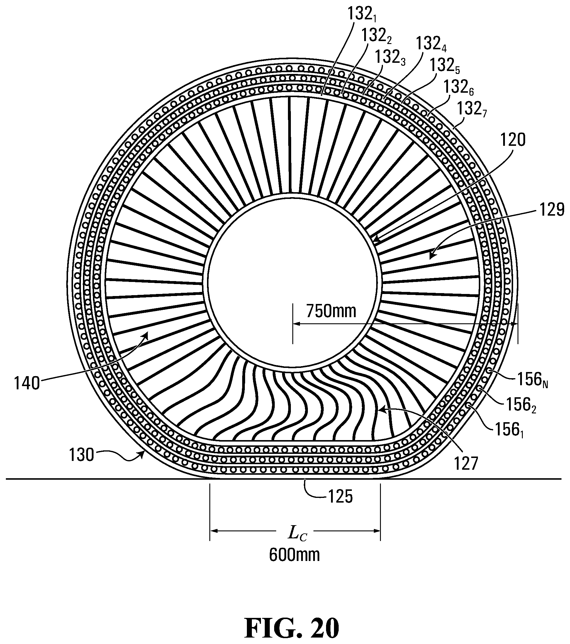
D00014

D00015
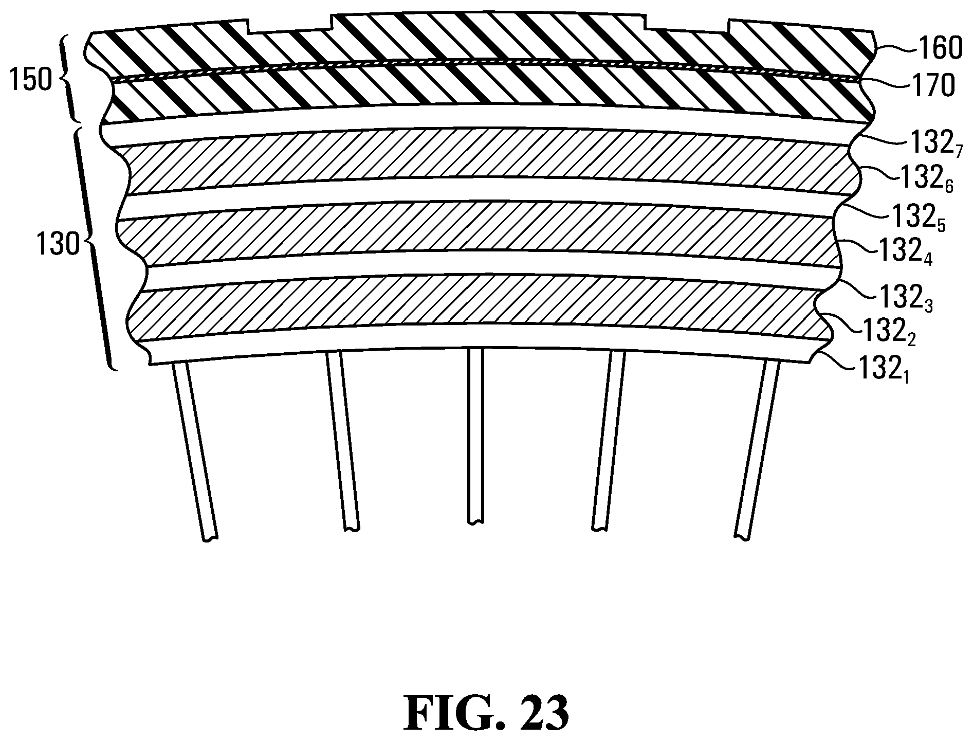
D00016
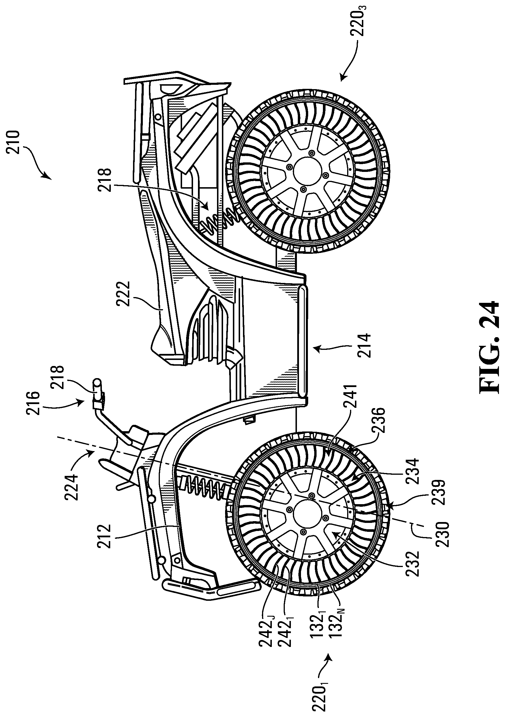
D00017
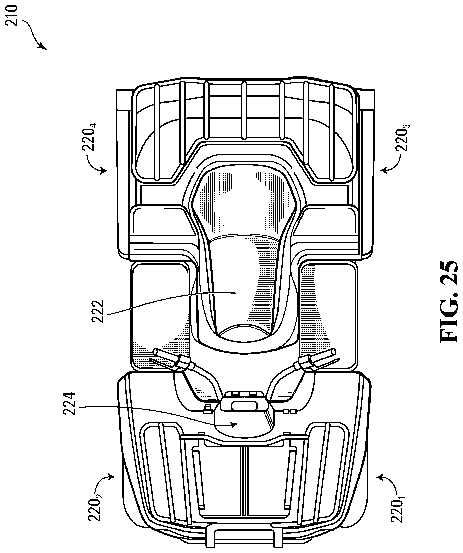
D00018
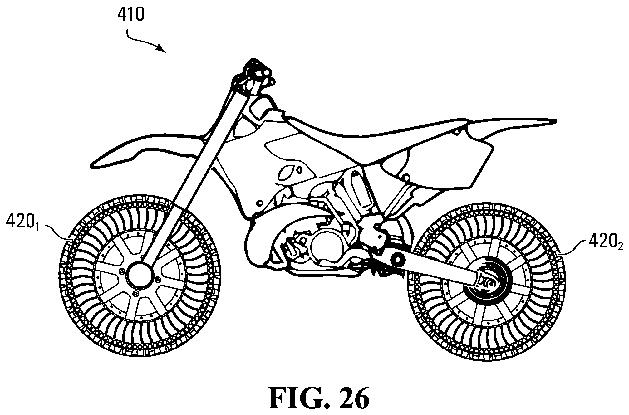
M00001

M00002

M00003

M00004

M00005

M00006

M00007

M00008

M00009
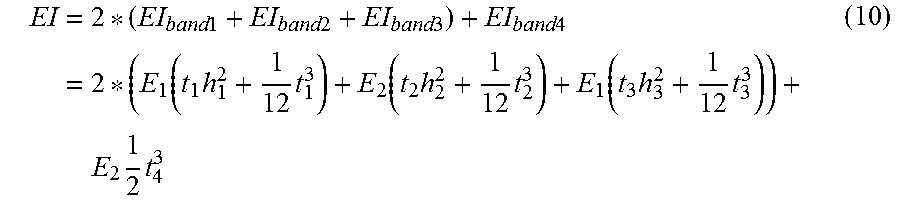
M00010

XML
uspto.report is an independent third-party trademark research tool that is not affiliated, endorsed, or sponsored by the United States Patent and Trademark Office (USPTO) or any other governmental organization. The information provided by uspto.report is based on publicly available data at the time of writing and is intended for informational purposes only.
While we strive to provide accurate and up-to-date information, we do not guarantee the accuracy, completeness, reliability, or suitability of the information displayed on this site. The use of this site is at your own risk. Any reliance you place on such information is therefore strictly at your own risk.
All official trademark data, including owner information, should be verified by visiting the official USPTO website at www.uspto.gov. This site is not intended to replace professional legal advice and should not be used as a substitute for consulting with a legal professional who is knowledgeable about trademark law.