Replacement heart valve commissure assembly
Adamek-Bowers , et al. March 9, 2
U.S. patent number 10,939,996 [Application Number 15/998,833] was granted by the patent office on 2021-03-09 for replacement heart valve commissure assembly. This patent grant is currently assigned to Boston Scientific Scimed, Inc.. The grantee listed for this patent is BOSTON SCIENTIFIC SCIMED, INC.. Invention is credited to Jasper Ellington Adamek-Bowers, Andrew James Harlan Backus, Brian D. Brandt, Michael P. Calomeni, Mimi Trinh Fitterer, Takashi H. Ino, Anh Thu Pham, Ali Salahieh, Jarad S. Waisblatt.


View All Diagrams
| United States Patent | 10,939,996 |
| Adamek-Bowers , et al. | March 9, 2021 |
Replacement heart valve commissure assembly
Abstract
A replacement heart valve commissure assembly may include a locking mechanism including a first locking portion spaced apart from a second locking portion in a delivery configuration and configured to engage with the second locking portion in a deployed configuration, wherein the first locking portion is longitudinally actuatable relative to the second locking portion between the delivery and deployed configurations. The commissure assembly may include a first valve leaflet and a second valve leaflet each secured to the first locking portion. A first sleeve portion of the first valve leaflet may be fixedly attached to a first fabric sleeve wrapped around a first leg of the first locking portion by a first filament, and a second sleeve portion of the second valve leaflet may be fixedly attached to a second fabric sleeve wrapped around a second leg of the first locking portion by a second filament.
| Inventors: | Adamek-Bowers; Jasper Ellington (San Francisco, CA), Salahieh; Ali (Saratoga, CA), Ino; Takashi H. (San Jose, CA), Backus; Andrew James Harlan (San Francisco, CA), Pham; Anh Thu (San Jose, CA), Brandt; Brian D. (Morgan Hill, CA), Fitterer; Mimi Trinh (Belmomt, CA), Calomeni; Michael P. (San Jose, CA), Waisblatt; Jarad S. (San Jose, CA) | ||||||||||
|---|---|---|---|---|---|---|---|---|---|---|---|
| Applicant: |
|
||||||||||
| Assignee: | Boston Scientific Scimed, Inc.
(Maple Grove, MN) |
||||||||||
| Family ID: | 1000005408037 | ||||||||||
| Appl. No.: | 15/998,833 | ||||||||||
| Filed: | August 16, 2018 |
Prior Publication Data
| Document Identifier | Publication Date | |
|---|---|---|
| US 20190053896 A1 | Feb 21, 2019 | |
Related U.S. Patent Documents
| Application Number | Filing Date | Patent Number | Issue Date | ||
|---|---|---|---|---|---|
| 62546194 | Aug 16, 2017 | ||||
| Current U.S. Class: | 1/1 |
| Current CPC Class: | A61F 2/2403 (20130101); A61F 2/2439 (20130101); A61F 2/2418 (20130101); A61F 2/2415 (20130101); A61F 2210/0014 (20130101); A61F 2210/0076 (20130101); A61F 2002/9534 (20130101); A61F 2220/0033 (20130101); A61F 2220/0066 (20130101); A61F 2/2427 (20130101); A61F 2220/0025 (20130101); A61F 2220/0008 (20130101); A61F 2220/0075 (20130101); A61F 2230/0052 (20130101); A61F 2002/9528 (20130101) |
| Current International Class: | A61F 2/24 (20060101); A61F 2/95 (20130101) |
References Cited [Referenced By]
U.S. Patent Documents
| 15192 | June 1856 | Peale |
| 2682057 | June 1954 | Lord |
| 2701559 | February 1955 | Cooper |
| 2832078 | April 1958 | Williams |
| 3029819 | April 1962 | Starks |
| 3099016 | July 1963 | Lowell |
| 3113586 | December 1963 | Edmark |
| 3130418 | April 1964 | Head et al. |
| 3143742 | August 1964 | Cromie |
| 3221006 | November 1965 | Moore et al. |
| 3334629 | August 1967 | Cohn |
| 3365728 | January 1968 | Edwards et al. |
| 3367364 | February 1968 | Cruz et al. |
| 3409013 | November 1968 | Henry |
| 3445916 | May 1969 | Schulte |
| 3540431 | November 1970 | Mobin-Uddin |
| 3548417 | December 1970 | Kischer et al. |
| 3570014 | March 1971 | Hancock |
| 3587115 | June 1971 | Shiley |
| 3592184 | July 1971 | Watkins et al. |
| 3628535 | December 1971 | Ostrowsky et al. |
| 3642004 | February 1972 | Osthagen et al. |
| 3657744 | April 1972 | Ersek |
| 3671979 | June 1972 | Moulopoulos |
| 3714671 | February 1973 | Goodenough et al. |
| 3725961 | April 1973 | Magovern et al. |
| 3755823 | September 1973 | Hancock |
| 3795246 | March 1974 | Sturgeon |
| 3839741 | October 1974 | Haller |
| 3868956 | March 1975 | Alfidi et al. |
| 3874388 | April 1975 | King et al. |
| 3983581 | October 1976 | Angell et al. |
| 3997923 | December 1976 | Possis |
| 4035849 | July 1977 | Angell et al. |
| 4056854 | November 1977 | Boretos et al. |
| 4084268 | April 1978 | Ionescu et al. |
| 4106129 | August 1978 | Carpentier et al. |
| 4222126 | September 1980 | Boretos et al. |
| 4233690 | November 1980 | Akins |
| 4265694 | May 1981 | Boretos et al. |
| 4291420 | September 1981 | Reul |
| 4297749 | November 1981 | Davis et al. |
| 4323358 | April 1982 | Lentz et al. |
| 4326306 | April 1982 | Poler |
| 4339831 | July 1982 | Johnson |
| 4343048 | August 1982 | Ross et al. |
| 4345340 | August 1982 | Rosen |
| 4373216 | February 1983 | Klawitter |
| 4406022 | September 1983 | Roy |
| 4423809 | January 1984 | Mazzocco |
| 4425908 | January 1984 | Simon |
| 4470157 | September 1984 | Love |
| 4484579 | November 1984 | Meno et al. |
| 4501030 | February 1985 | Lane |
| 4531943 | July 1985 | Tassel et al. |
| 4535483 | August 1985 | Klawitter et al. |
| 4574803 | March 1986 | Storz |
| 4580568 | April 1986 | Gianturco |
| 4592340 | June 1986 | Boyles |
| 4602911 | July 1986 | Ahmadi et al. |
| 4605407 | August 1986 | Black et al. |
| 4610688 | September 1986 | Silvestrini et al. |
| 4612011 | September 1986 | Kautzky |
| 4617932 | October 1986 | Kornberg |
| 4643732 | February 1987 | Pietsch et al. |
| 4647283 | March 1987 | Carpentier et al. |
| 4648881 | March 1987 | Carpentier et al. |
| 4655218 | April 1987 | Kulik et al. |
| 4655771 | April 1987 | Wallsten et al. |
| 4662885 | May 1987 | DiPisa |
| 4665906 | May 1987 | Jervis |
| 4680031 | July 1987 | Alonso |
| 4692164 | September 1987 | Dzemeshkevich et al. |
| 4705516 | November 1987 | Barone et al. |
| 4710192 | December 1987 | Liotta et al. |
| 4733665 | March 1988 | Palmaz et al. |
| 4755181 | July 1988 | Igoe |
| 4759758 | July 1988 | Gabbay |
| 4777951 | October 1988 | Cribier et al. |
| 4787899 | November 1988 | Lazarus |
| 4787901 | November 1988 | Baykut |
| 4796629 | January 1989 | Grayzel |
| 4819751 | April 1989 | Shimada et al. |
| 4829990 | May 1989 | Thuroff et al. |
| 4834755 | May 1989 | Silvestrini et al. |
| 4851001 | July 1989 | Taheri |
| 4856516 | August 1989 | Hillstead |
| 4865600 | September 1989 | Carpentier et al. |
| 4872874 | October 1989 | Taheri |
| 4873978 | October 1989 | Ginsburg |
| 4878495 | November 1989 | Grayzel |
| 4878906 | November 1989 | Lindemann et al. |
| 4883458 | November 1989 | Shiber |
| 4885005 | December 1989 | Nashef et al. |
| 4909252 | March 1990 | Goldberger |
| 4917102 | April 1990 | Miller et al. |
| 4922905 | May 1990 | Strecker |
| 4927426 | May 1990 | Dretler |
| 4954126 | September 1990 | Wallsten |
| 4966604 | October 1990 | Reiss |
| 4969890 | November 1990 | Sugita et al. |
| 4979939 | December 1990 | Shiber |
| 4986830 | January 1991 | Owens et al. |
| 4994077 | February 1991 | Dobben |
| 5002556 | March 1991 | Ishida et al. |
| 5002559 | March 1991 | Tower |
| 5007896 | April 1991 | Shiber |
| 5026366 | June 1991 | Leckrone |
| 5032128 | July 1991 | Alonso |
| 5037434 | August 1991 | Lane |
| 5047041 | September 1991 | Samuels |
| 5064435 | November 1991 | Porter |
| 5080668 | January 1992 | Bolz et al. |
| 5085635 | February 1992 | Cragg |
| 5089015 | February 1992 | Ross |
| 5122154 | June 1992 | Rhodes |
| 5132473 | July 1992 | Furutaka et al. |
| 5141494 | August 1992 | Danforth et al. |
| 5152771 | October 1992 | Sabbaghian et al. |
| 5159937 | November 1992 | Tremulis |
| 5161547 | November 1992 | Tower |
| 5163953 | November 1992 | Vince |
| 5167628 | December 1992 | Boyles |
| 5209741 | May 1993 | Spaeth |
| 5215541 | June 1993 | Nashef et al. |
| 5217481 | June 1993 | Barbara |
| 5217483 | June 1993 | Tower |
| 5238004 | August 1993 | Sahatjian et al. |
| 5258023 | November 1993 | Reger |
| 5258042 | November 1993 | Mehta |
| 5282847 | February 1994 | Trescony et al. |
| 5295958 | March 1994 | Shturman |
| 5332402 | July 1994 | Teitelbaum |
| 5336258 | August 1994 | Quintero et al. |
| 5350398 | September 1994 | Pavcnik et al. |
| 5360444 | November 1994 | Kusuhara |
| 5370685 | December 1994 | Stevens |
| 5389106 | February 1995 | Tower |
| 5397351 | March 1995 | Pavcnik et al. |
| 5409019 | April 1995 | Wilk |
| 5411552 | May 1995 | Andersen et al. |
| 5425739 | June 1995 | Jessen |
| 5425762 | June 1995 | Muller |
| 5431676 | July 1995 | Dubrul et al. |
| 5443446 | August 1995 | Shturman |
| 5443449 | August 1995 | Buelna |
| 5443477 | August 1995 | Marin et al. |
| 5443495 | August 1995 | Buscemi et al. |
| 5443499 | August 1995 | Schmitt |
| 5469868 | November 1995 | Reger |
| 5476506 | December 1995 | Lunn |
| 5476510 | December 1995 | Eberhardt et al. |
| 5480423 | January 1996 | Ravenscroft et al. |
| 5480424 | January 1996 | Cox |
| 5489297 | February 1996 | Duran |
| 5500014 | March 1996 | Quijano et al. |
| 5507767 | April 1996 | Maeda et al. |
| 5522881 | June 1996 | Lentz |
| 5534007 | July 1996 | Germain et al. |
| 5545133 | August 1996 | Burns et al. |
| 5545209 | August 1996 | Roberts et al. |
| 5545211 | August 1996 | An et al. |
| 5545214 | August 1996 | Stevens |
| 5549665 | August 1996 | Vesely et al. |
| 5554185 | September 1996 | Block et al. |
| 5571175 | November 1996 | Vanney et al. |
| 5571215 | November 1996 | Sterman et al. |
| 5573520 | November 1996 | Schwartz et al. |
| 5575818 | November 1996 | Pinchuk |
| 5591185 | January 1997 | Kilmer et al. |
| 5591195 | January 1997 | Taheri et al. |
| 5607464 | March 1997 | Trescony et al. |
| 5609626 | March 1997 | Quijano et al. |
| 5628784 | May 1997 | Strecker |
| 5645559 | July 1997 | Hachtman et al. |
| 5653745 | August 1997 | Trescony et al. |
| 5662671 | September 1997 | Barbut et al. |
| 5667523 | September 1997 | Bynon et al. |
| 5674277 | October 1997 | Freitag |
| 5681345 | October 1997 | Euteneuer |
| 5693083 | December 1997 | Baker et al. |
| 5693088 | December 1997 | Lazarus |
| 5693310 | December 1997 | Gries et al. |
| 5695498 | December 1997 | Tower |
| 5709713 | January 1998 | Evans et al. |
| 5713951 | February 1998 | Garrison et al. |
| 5713953 | February 1998 | Vallana et al. |
| 5716370 | February 1998 | Williamson et al. |
| 5716417 | February 1998 | Girard et al. |
| 5720391 | February 1998 | Dohm et al. |
| 5725549 | March 1998 | Lam |
| 5728068 | March 1998 | Leone et al. |
| 5733325 | March 1998 | Robinson et al. |
| 5735842 | April 1998 | Krueger et al. |
| 5749890 | May 1998 | Shaknovich |
| 5755783 | May 1998 | Stobie et al. |
| 5756476 | May 1998 | Epstein et al. |
| 5769812 | June 1998 | Stevens et al. |
| 5769882 | June 1998 | Fogarty et al. |
| 5772609 | June 1998 | Nguyen et al. |
| 5776188 | July 1998 | Shepherd et al. |
| 5782904 | July 1998 | White et al. |
| 5800456 | September 1998 | Maeda et al. |
| 5800531 | September 1998 | Cosgrove et al. |
| 5807405 | September 1998 | Vanney et al. |
| 5817126 | October 1998 | Imran |
| 5824037 | October 1998 | Fogarty et al. |
| 5824041 | October 1998 | Lenker et al. |
| 5824043 | October 1998 | Cottone |
| 5824053 | October 1998 | Khosravi et al. |
| 5824055 | October 1998 | Spiridigliozzi et al. |
| 5824056 | October 1998 | Rosenberg |
| 5824064 | October 1998 | Taheri |
| 5840081 | November 1998 | Andersen et al. |
| 5843158 | December 1998 | Lenker et al. |
| 5843161 | December 1998 | Solovay |
| 5855597 | January 1999 | Jayaraman |
| 5855601 | January 1999 | Bessler et al. |
| 5855602 | January 1999 | Angell |
| 5860966 | January 1999 | Tower |
| 5860996 | January 1999 | Urban et al. |
| 5861024 | January 1999 | Rashidi |
| 5861028 | January 1999 | Angell |
| 5868783 | February 1999 | Tower |
| 5876419 | March 1999 | Carpenter et al. |
| 5876448 | March 1999 | Thompson et al. |
| 5885228 | March 1999 | Rosenman et al. |
| 5888201 | March 1999 | Stinson et al. |
| 5891191 | April 1999 | Stinson |
| 5895399 | April 1999 | Barbut et al. |
| 5906619 | May 1999 | Olson et al. |
| 5907893 | June 1999 | Zadno-Azizi et al. |
| 5910154 | June 1999 | Tsugita et al. |
| 5911734 | June 1999 | Tsugita et al. |
| 5925063 | July 1999 | Khosravi |
| 5944738 | August 1999 | Amplatz et al. |
| 5954766 | September 1999 | Zadno-Azizi et al. |
| 5957949 | September 1999 | Leonhardt et al. |
| 5968070 | October 1999 | Bley et al. |
| 5984957 | November 1999 | Laptewicz et al. |
| 5984959 | November 1999 | Robertson et al. |
| 5993469 | November 1999 | McKenzie et al. |
| 5997557 | December 1999 | Barbut et al. |
| 6010522 | January 2000 | Barbut et al. |
| 6015431 | January 2000 | Thornton et al. |
| 6022370 | February 2000 | Tower |
| 6027520 | February 2000 | Tsugita et al. |
| 6027525 | February 2000 | Suh et al. |
| 6042598 | March 2000 | Tsugita et al. |
| 6042607 | March 2000 | Williamson et al. |
| 6051014 | April 2000 | Jang |
| 6059827 | May 2000 | Fenton |
| 6074418 | June 2000 | Buchanan et al. |
| 6093203 | July 2000 | Uflacker |
| 6096074 | August 2000 | Pedros |
| 6110198 | August 2000 | Fogarty et al. |
| 6123723 | September 2000 | Konya et al. |
| 6132473 | October 2000 | Williams et al. |
| 6139510 | October 2000 | Palermo |
| 6142987 | November 2000 | Tsugita |
| 6146366 | November 2000 | Schachar |
| 6162245 | December 2000 | Jayaraman |
| 6165200 | December 2000 | Tsugita et al. |
| 6165209 | December 2000 | Patterson et al. |
| 6168579 | January 2001 | Tsugita |
| 6168614 | January 2001 | Andersen et al. |
| 6171327 | January 2001 | Daniel et al. |
| 6171335 | January 2001 | Wheatley et al. |
| 6179859 | January 2001 | Bates et al. |
| 6187016 | February 2001 | Hedges et al. |
| 6197053 | March 2001 | Cosgrove et al. |
| 6200336 | March 2001 | Pavcnik et al. |
| 6206911 | March 2001 | Milo |
| 6214036 | April 2001 | Letendre et al. |
| 6221006 | April 2001 | Dubrul et al. |
| 6221091 | April 2001 | Khosravi |
| 6221096 | April 2001 | Alba et al. |
| 6221100 | April 2001 | Strecker |
| 6231544 | May 2001 | Tsugita et al. |
| 6231551 | May 2001 | Barbut |
| 6241757 | June 2001 | An et al. |
| 6245102 | June 2001 | Jayaraman |
| 6251135 | June 2001 | Stinson et al. |
| 6258114 | July 2001 | Konya et al. |
| 6258115 | July 2001 | Dubrul |
| 6258120 | July 2001 | McKenzie et al. |
| 6258129 | July 2001 | Dybdal et al. |
| 6267783 | July 2001 | Letendre et al. |
| 6270513 | August 2001 | Tsugita et al. |
| 6277555 | August 2001 | Duran et al. |
| 6299637 | October 2001 | Shaolian et al. |
| 6302906 | October 2001 | Goicoechea et al. |
| 6306164 | October 2001 | Kujawski |
| 6309417 | October 2001 | Spence et al. |
| 6312465 | November 2001 | Griffin et al. |
| 6319281 | November 2001 | Patel |
| 6327772 | December 2001 | Zadno-Azizi et al. |
| 6336934 | January 2002 | Gilson et al. |
| 6336937 | January 2002 | Vonesh et al. |
| 6338735 | January 2002 | Stevens |
| 6346116 | February 2002 | Brooks et al. |
| 6348063 | February 2002 | Yassour et al. |
| 6352554 | March 2002 | Paulis |
| 6352708 | March 2002 | Duran et al. |
| 6361545 | March 2002 | Macoviak et al. |
| 6363938 | April 2002 | Saadat et al. |
| 6364895 | April 2002 | Greenhalgh |
| 6371970 | April 2002 | Khosravi et al. |
| 6371983 | April 2002 | Lane |
| 6379383 | April 2002 | Palmaz et al. |
| 6387122 | May 2002 | Cragg |
| 6398807 | June 2002 | Chouinard et al. |
| 6402736 | June 2002 | Brown et al. |
| 6409750 | June 2002 | Hyodoh et al. |
| 6416510 | July 2002 | Altman et al. |
| 6425916 | July 2002 | Garrison et al. |
| 6440164 | August 2002 | DiMatteo et al. |
| 6454799 | September 2002 | Schreck |
| 6458153 | October 2002 | Bailey et al. |
| 6461382 | October 2002 | Cao |
| 6468303 | October 2002 | Amplatz et al. |
| 6468660 | October 2002 | Ogle et al. |
| 6475239 | November 2002 | Campbell et al. |
| 6482228 | November 2002 | Norred |
| 6485501 | November 2002 | Green |
| 6485502 | November 2002 | Michael et al. |
| 6488704 | December 2002 | Connelly et al. |
| 6494909 | December 2002 | Greenhalgh |
| 6503272 | January 2003 | Duerig et al. |
| 6508803 | January 2003 | Horikawa et al. |
| 6508833 | January 2003 | Pavcnik et al. |
| 6527800 | March 2003 | McGuckin et al. |
| 6530949 | March 2003 | Konya et al. |
| 6530952 | March 2003 | Vesely |
| 6537297 | March 2003 | Tsugita et al. |
| 6540768 | April 2003 | Diaz et al. |
| 6540782 | April 2003 | Snyders |
| 6562058 | May 2003 | Seguin et al. |
| 6569196 | May 2003 | Vesely |
| 6572643 | June 2003 | Gharibadeh |
| 6585766 | July 2003 | Huynh et al. |
| 6592546 | July 2003 | Barbut et al. |
| 6592614 | July 2003 | Lenker et al. |
| 6605112 | August 2003 | Moll et al. |
| 6610077 | August 2003 | Hancock et al. |
| 6616682 | September 2003 | Joergensen et al. |
| 6622604 | September 2003 | Chouinard et al. |
| 6623518 | September 2003 | Thompson et al. |
| 6623521 | September 2003 | Steinke et al. |
| 6626938 | September 2003 | Butaric et al. |
| 6632243 | October 2003 | Zadno-Azizi et al. |
| 6635068 | October 2003 | Dubrul et al. |
| 6635079 | October 2003 | Unsworth et al. |
| 6635080 | October 2003 | Lauterjung et al. |
| 6652571 | November 2003 | White et al. |
| 6652578 | November 2003 | Bailey et al. |
| 6663588 | December 2003 | DuBois et al. |
| 6663663 | December 2003 | Kim et al. |
| 6663667 | December 2003 | Dehdashtian et al. |
| 6669724 | December 2003 | Park et al. |
| 6673089 | January 2004 | Yassour et al. |
| 6673109 | January 2004 | Cox |
| 6676668 | January 2004 | Mercereau et al. |
| 6676692 | January 2004 | Rabkin et al. |
| 6676698 | January 2004 | McGuckin et al. |
| 6682543 | January 2004 | Barbut et al. |
| 6682558 | January 2004 | Tu et al. |
| 6682559 | January 2004 | Myers et al. |
| 6685739 | February 2004 | DiMatteo et al. |
| 6689144 | February 2004 | Gerberding |
| 6689164 | February 2004 | Seguin |
| 6692512 | February 2004 | Jang |
| 6695864 | February 2004 | Macoviak et al. |
| 6695865 | February 2004 | Boyle et al. |
| 6702851 | March 2004 | Chinn et al. |
| 6712842 | March 2004 | Gifford et al. |
| 6712843 | March 2004 | Elliott |
| 6714842 | March 2004 | Ito |
| 6719789 | April 2004 | Cox |
| 6723116 | April 2004 | Taheri |
| 6729356 | May 2004 | Baker et al. |
| 6730118 | May 2004 | Spenser et al. |
| 6730377 | May 2004 | Wang |
| 6733525 | May 2004 | Yang et al. |
| 6736846 | May 2004 | Cox |
| 6752828 | June 2004 | Thornton |
| 6755854 | June 2004 | Gillick et al. |
| 6758855 | July 2004 | Fulton et al. |
| 6764503 | July 2004 | Ishimaru |
| 6764509 | July 2004 | Chinn et al. |
| 6767345 | July 2004 | Germain et al. |
| 6769434 | August 2004 | Liddicoat et al. |
| 6773454 | August 2004 | Wholey et al. |
| 6773456 | August 2004 | Gordon et al. |
| 6776791 | August 2004 | Stallings et al. |
| 6786925 | September 2004 | Schoon et al. |
| 6790229 | September 2004 | Berreklouw |
| 6790230 | September 2004 | Beyersdorf et al. |
| 6790237 | September 2004 | Stinson |
| 6792979 | September 2004 | Konya et al. |
| 6797002 | September 2004 | Spence et al. |
| 6814746 | November 2004 | Thompson et al. |
| 6814754 | November 2004 | Greenhalgh |
| 6821297 | November 2004 | Snyders |
| 6824041 | November 2004 | Grieder et al. |
| 6830585 | December 2004 | Artof et al. |
| 6837901 | January 2005 | Rabkin et al. |
| 6840957 | January 2005 | DiMatteo et al. |
| 6843802 | January 2005 | Villalobos et al. |
| 6849085 | February 2005 | Marton |
| 6863668 | March 2005 | Gillespie et al. |
| 6863688 | March 2005 | Ralph et al. |
| 6866650 | March 2005 | Stevens et al. |
| 6866669 | March 2005 | Buzzard et al. |
| 6872223 | March 2005 | Roberts et al. |
| 6872226 | March 2005 | Cali et al. |
| 6875231 | April 2005 | Anduiza et al. |
| 6881220 | April 2005 | Edwin et al. |
| 6887266 | May 2005 | Williams et al. |
| 6890340 | May 2005 | Duane |
| 6893459 | May 2005 | Macoviak |
| 6893460 | May 2005 | Spenser et al. |
| 6896690 | May 2005 | Lambrecht et al. |
| 6905743 | June 2005 | Chen et al. |
| 6908481 | June 2005 | Cribier |
| 6911036 | June 2005 | Douk et al. |
| 6911040 | June 2005 | Johnson et al. |
| 6911043 | June 2005 | Myers et al. |
| 6936058 | August 2005 | Forde et al. |
| 6936067 | August 2005 | Buchanan |
| 6939352 | September 2005 | Buzzard et al. |
| 6951571 | October 2005 | Srivastava |
| 6953332 | October 2005 | Kurk et al. |
| 6964673 | November 2005 | Tsugita et al. |
| 6969395 | November 2005 | Eskuri |
| 6972025 | December 2005 | WasDyke |
| 6974464 | December 2005 | Quijano et al. |
| 6974474 | December 2005 | Pavcnik et al. |
| 6974476 | December 2005 | McGuckin et al. |
| 6979350 | December 2005 | Moll et al. |
| 6984242 | January 2006 | Campbell et al. |
| 6989027 | January 2006 | Allen et al. |
| 7004176 | February 2006 | Lau |
| 7011681 | March 2006 | Vesely |
| 7018406 | March 2006 | Seguin et al. |
| 7025791 | April 2006 | Levine et al. |
| 7037331 | May 2006 | Mitelberg et al. |
| 7041132 | May 2006 | Quijano et al. |
| 7044966 | May 2006 | Svanidze et al. |
| 7097658 | August 2006 | Oktay |
| 7108715 | September 2006 | Lawrence-Brown et al. |
| 7122020 | October 2006 | Mogul |
| 7125418 | October 2006 | Duran et al. |
| 7141063 | November 2006 | White et al. |
| 7147663 | December 2006 | Berg et al. |
| 7166097 | January 2007 | Barbut |
| 7175652 | February 2007 | Cook et al. |
| 7175653 | February 2007 | Gaber |
| 7175654 | February 2007 | Bonsignore et al. |
| 7175656 | February 2007 | Khairkhahan |
| 7189258 | March 2007 | Johnson et al. |
| 7191018 | March 2007 | Gielen et al. |
| 7201772 | April 2007 | Schwammenthal et al. |
| 7235093 | June 2007 | Gregorich |
| 7252682 | August 2007 | Seguin |
| 7258696 | August 2007 | Rabkin et al. |
| 7261732 | August 2007 | Justino |
| 7264632 | September 2007 | Wright et al. |
| 7267686 | September 2007 | DiMatteo et al. |
| 7276078 | October 2007 | Spenser et al. |
| 7322932 | January 2008 | Xie et al. |
| 7326236 | February 2008 | Andreas et al. |
| 7329279 | February 2008 | Haug et al. |
| 7331993 | February 2008 | White |
| 7374560 | May 2008 | Ressemann et al. |
| 7381219 | June 2008 | Salahieh et al. |
| 7381220 | June 2008 | Macoviak et al. |
| 7399315 | July 2008 | Iobbi |
| 7445631 | November 2008 | Salahieh et al. |
| 7470285 | December 2008 | Nugent et al. |
| 7491232 | February 2009 | Bolduc et al. |
| 7510574 | March 2009 | L et al. |
| 7524330 | April 2009 | Berreklouw |
| 7530995 | May 2009 | Quijano et al. |
| 7544206 | June 2009 | Cohn |
| 7622276 | November 2009 | Cunanan et al. |
| 7628803 | December 2009 | Pavcnik et al. |
| 7632298 | December 2009 | Hijlkema et al. |
| 7641687 | January 2010 | Chinn et al. |
| 7674282 | March 2010 | Wu et al. |
| 7712606 | May 2010 | Salahieh et al. |
| 7722638 | May 2010 | Deyette et al. |
| 7722662 | May 2010 | Steinke et al. |
| 7722666 | May 2010 | Lafontaine |
| 7731742 | June 2010 | Schlick et al. |
| 7736388 | June 2010 | Goldfarb et al. |
| 7748389 | July 2010 | Salahieh et al. |
| 7758625 | July 2010 | Wu et al. |
| 7780725 | August 2010 | Haug et al. |
| 7799065 | September 2010 | Pappas |
| 7803185 | September 2010 | Gabbay |
| 7824442 | November 2010 | Salahieh et al. |
| 7824443 | November 2010 | Salahieh et al. |
| 7833262 | November 2010 | McGuckin et al. |
| 7846204 | December 2010 | Letac et al. |
| 7857845 | December 2010 | Stacchino et al. |
| 7892292 | February 2011 | Stack et al. |
| 7918880 | April 2011 | Austin |
| 7938851 | May 2011 | Olson et al. |
| 7959666 | June 2011 | Salahieh et al. |
| 7959672 | June 2011 | Salahieh et al. |
| 7988724 | August 2011 | Salahieh et al. |
| 8048153 | November 2011 | Salahieh et al. |
| 8052749 | November 2011 | Salahieh et al. |
| 8136659 | March 2012 | Salahieh et al. |
| 8157853 | April 2012 | Laske et al. |
| 8172896 | May 2012 | McNamara et al. |
| 8182528 | May 2012 | Salahieh et al. |
| 8192351 | June 2012 | Fishler et al. |
| 8226710 | July 2012 | Nguyen et al. |
| 8231670 | July 2012 | Salahieh et al. |
| 8236049 | August 2012 | Rowe et al. |
| 8246678 | August 2012 | Salahieh et al. |
| 8252051 | August 2012 | Chau et al. |
| 8252052 | August 2012 | Salahieh et al. |
| 8287584 | October 2012 | Salahieh et al. |
| 8308798 | November 2012 | Pintor et al. |
| 8317858 | November 2012 | Straubinger et al. |
| 8323335 | December 2012 | Rowe et al. |
| 8328868 | December 2012 | Paul et al. |
| 8343213 | January 2013 | Salahieh et al. |
| 8376865 | February 2013 | Forster et al. |
| 8377117 | February 2013 | Keidar et al. |
| 8398708 | March 2013 | Meiri et al. |
| 8403983 | March 2013 | Quadri et al. |
| 8414644 | April 2013 | Quadri et al. |
| 8579962 | November 2013 | Salahieh et al. |
| 8603160 | December 2013 | Salahieh et al. |
| 8617236 | December 2013 | Paul et al. |
| 8623074 | January 2014 | Ryan |
| 8623076 | January 2014 | Salahieh et al. |
| 8623078 | January 2014 | Salahieh et al. |
| 8668733 | March 2014 | Haug et al. |
| 8673000 | March 2014 | Tabor et al. |
| 8696743 | April 2014 | Holecek et al. |
| 8828078 | September 2014 | Salahieh et al. |
| 8840662 | September 2014 | Salahieh et al. |
| 8840663 | September 2014 | Salahieh et al. |
| 8858620 | October 2014 | Salahieh et al. |
| 8894703 | November 2014 | Salahieh et al. |
| 8951299 | February 2015 | Paul et al. |
| 8992608 | March 2015 | Haug et al. |
| 9005273 | April 2015 | Salahieh et al. |
| 9011521 | April 2015 | Haug et al. |
| 9168131 | October 2015 | Yohanan et al. |
| 2001/0002445 | May 2001 | Vesely |
| 2001/0007956 | July 2001 | Letac et al. |
| 2001/0010017 | July 2001 | Letac et al. |
| 2001/0021872 | September 2001 | Bailey et al. |
| 2001/0025196 | September 2001 | Chinn et al. |
| 2001/0027338 | October 2001 | Greenberg |
| 2001/0032013 | October 2001 | Marton |
| 2001/0039450 | November 2001 | Pavcnik et al. |
| 2001/0041928 | November 2001 | Pavcnik et al. |
| 2001/0041930 | November 2001 | Globerman et al. |
| 2001/0044634 | November 2001 | Michael et al. |
| 2001/0044652 | November 2001 | Moore |
| 2001/0044656 | November 2001 | Williamson et al. |
| 2002/0002396 | January 2002 | Fulkerson |
| 2002/0010489 | January 2002 | Grayzel et al. |
| 2002/0026233 | February 2002 | Shaknovich |
| 2002/0029014 | March 2002 | Jayaraman |
| 2002/0029981 | March 2002 | Nigam |
| 2002/0032480 | March 2002 | Spence et al. |
| 2002/0032481 | March 2002 | Gabbay |
| 2002/0042651 | April 2002 | Liddicoat et al. |
| 2002/0052651 | May 2002 | Myers et al. |
| 2002/0055767 | May 2002 | Forde et al. |
| 2002/0055769 | May 2002 | Wang |
| 2002/0055774 | May 2002 | Liddicoat |
| 2002/0058987 | May 2002 | Butaric et al. |
| 2002/0058995 | May 2002 | Stevens |
| 2002/0077696 | June 2002 | Zadno-Azizi et al. |
| 2002/0082609 | June 2002 | Green |
| 2002/0095173 | July 2002 | Mazzocchi et al. |
| 2002/0095209 | July 2002 | Zadno-Azizi et al. |
| 2002/0111674 | August 2002 | Chouinard et al. |
| 2002/0120328 | August 2002 | Pathak et al. |
| 2002/0123802 | September 2002 | Snyders |
| 2002/0138138 | September 2002 | Yang |
| 2002/0151970 | October 2002 | Garrison et al. |
| 2002/0156522 | October 2002 | Ivancev et al. |
| 2002/0161390 | October 2002 | Mouw |
| 2002/0161392 | October 2002 | Dubrul |
| 2002/0161394 | October 2002 | Macoviak et al. |
| 2002/0165576 | November 2002 | Boyle et al. |
| 2002/0177766 | November 2002 | Mogul |
| 2002/0183781 | December 2002 | Casey et al. |
| 2002/0188341 | December 2002 | Elliott |
| 2002/0188344 | December 2002 | Bolea et al. |
| 2002/0193871 | December 2002 | Beyersdorf et al. |
| 2003/0014104 | January 2003 | Cribier |
| 2003/0023303 | January 2003 | Palmaz et al. |
| 2003/0028247 | February 2003 | Cali |
| 2003/0036791 | February 2003 | Philipp et al. |
| 2003/0040736 | February 2003 | Stevens et al. |
| 2003/0040771 | February 2003 | Hyodoh et al. |
| 2003/0040772 | February 2003 | Hyodoh et al. |
| 2003/0040791 | February 2003 | Oktay |
| 2003/0040792 | February 2003 | Gabbay |
| 2003/0050694 | March 2003 | Yang et al. |
| 2003/0055495 | March 2003 | Pease et al. |
| 2003/0057156 | March 2003 | Peterson et al. |
| 2003/0060844 | March 2003 | Borillo et al. |
| 2003/0069492 | April 2003 | Abrams et al. |
| 2003/0069646 | April 2003 | Stinson |
| 2003/0070944 | April 2003 | Nigam |
| 2003/0074058 | April 2003 | Sherry |
| 2003/0093145 | May 2003 | Lawrence-Brown et al. |
| 2003/0100918 | May 2003 | Duane |
| 2003/0100919 | May 2003 | Hopkins et al. |
| 2003/0109924 | June 2003 | Cribier |
| 2003/0109930 | June 2003 | Bluni et al. |
| 2003/0114912 | June 2003 | Sequin et al. |
| 2003/0114913 | June 2003 | Spenser et al. |
| 2003/0125795 | July 2003 | Pavcnik et al. |
| 2003/0130729 | July 2003 | Paniagua et al. |
| 2003/0135257 | July 2003 | Taheri |
| 2003/0144732 | July 2003 | Cosgrove et al. |
| 2003/0149475 | August 2003 | Hyodoh et al. |
| 2003/0149476 | August 2003 | Damm et al. |
| 2003/0149478 | August 2003 | Figulla et al. |
| 2003/0153974 | August 2003 | Spenser et al. |
| 2003/0165352 | September 2003 | Ibrahim et al. |
| 2003/0171803 | September 2003 | Shimon |
| 2003/0176884 | September 2003 | Berrada et al. |
| 2003/0181850 | September 2003 | Diamond et al. |
| 2003/0187495 | October 2003 | Cully et al. |
| 2003/0191516 | October 2003 | Weldon et al. |
| 2003/0195609 | October 2003 | Berenstein et al. |
| 2003/0199759 | October 2003 | Richard |
| 2003/0199913 | October 2003 | Dubrul et al. |
| 2003/0199971 | October 2003 | Tower et al. |
| 2003/0199972 | October 2003 | Zadno-Azizi et al. |
| 2003/0204249 | October 2003 | Letort |
| 2003/0208224 | November 2003 | Broome |
| 2003/0212429 | November 2003 | Keegan et al. |
| 2003/0212452 | November 2003 | Zadno-Azizi et al. |
| 2003/0212454 | November 2003 | Scott et al. |
| 2003/0216774 | November 2003 | Larson |
| 2003/0225445 | December 2003 | Derus et al. |
| 2003/0229390 | December 2003 | Ashton et al. |
| 2003/0233117 | December 2003 | Adams et al. |
| 2003/0236567 | December 2003 | Elliot |
| 2004/0019374 | January 2004 | Hojeibane et al. |
| 2004/0033364 | February 2004 | Spiridigliozzi et al. |
| 2004/0034411 | February 2004 | Quijano et al. |
| 2004/0039436 | February 2004 | Spenser et al. |
| 2004/0049224 | March 2004 | Buehlmann et al. |
| 2004/0049226 | March 2004 | Keegan et al. |
| 2004/0049262 | March 2004 | Obermiller et al. |
| 2004/0049266 | March 2004 | Anduiza et al. |
| 2004/0059409 | March 2004 | Stenzel |
| 2004/0073198 | April 2004 | Gilson et al. |
| 2004/0082904 | April 2004 | Houde et al. |
| 2004/0082967 | April 2004 | Broome et al. |
| 2004/0082989 | April 2004 | Cook et al. |
| 2004/0087982 | May 2004 | Eskuri |
| 2004/0088045 | May 2004 | Cox |
| 2004/0093016 | May 2004 | Root et al. |
| 2004/0093060 | May 2004 | Seguin et al. |
| 2004/0097788 | May 2004 | Mourlas et al. |
| 2004/0098022 | May 2004 | Barone |
| 2004/0098098 | May 2004 | McGuckin et al. |
| 2004/0098099 | May 2004 | McCullagh et al. |
| 2004/0098112 | May 2004 | DiMatteo et al. |
| 2004/0107004 | June 2004 | Levine et al. |
| 2004/0111096 | June 2004 | Tu et al. |
| 2004/0116951 | June 2004 | Rosengart |
| 2004/0116999 | June 2004 | Ledergerber |
| 2004/0117004 | June 2004 | Osborne et al. |
| 2004/0117009 | June 2004 | Cali et al. |
| 2004/0122468 | June 2004 | Yodfat et al. |
| 2004/0122516 | June 2004 | Fogarty et al. |
| 2004/0127936 | July 2004 | Salahieh et al. |
| 2004/0127979 | July 2004 | Wilson et al. |
| 2004/0133274 | July 2004 | Webler et al. |
| 2004/0138694 | July 2004 | Tran et al. |
| 2004/0138742 | July 2004 | Myers et al. |
| 2004/0138743 | July 2004 | Myers et al. |
| 2004/0148018 | July 2004 | Carpentier et al. |
| 2004/0148021 | July 2004 | Cartledge et al. |
| 2004/0153094 | August 2004 | Dunfee et al. |
| 2004/0158277 | August 2004 | Lowe et al. |
| 2004/0167565 | August 2004 | Beulke et al. |
| 2004/0167620 | August 2004 | Ortiz et al. |
| 2004/0181140 | September 2004 | Falwell et al. |
| 2004/0186558 | September 2004 | Pavcnik et al. |
| 2004/0186563 | September 2004 | Lobbi |
| 2004/0193261 | September 2004 | Berreklouw |
| 2004/0197695 | October 2004 | Aono |
| 2004/0199245 | October 2004 | Lauterjung |
| 2004/0204755 | October 2004 | Robin |
| 2004/0210304 | October 2004 | Seguin et al. |
| 2004/0210306 | October 2004 | Quijano et al. |
| 2004/0210307 | October 2004 | Khairkhahan |
| 2004/0215331 | October 2004 | Chew et al. |
| 2004/0215333 | October 2004 | Duran et al. |
| 2004/0215339 | October 2004 | Drasler et al. |
| 2004/0220655 | November 2004 | Swanson et al. |
| 2004/0225321 | November 2004 | Krolik et al. |
| 2004/0225353 | November 2004 | McGuckin et al. |
| 2004/0225354 | November 2004 | Allen et al. |
| 2004/0225355 | November 2004 | Stevens |
| 2004/0243221 | December 2004 | Fawzi et al. |
| 2004/0254636 | December 2004 | Flagle et al. |
| 2004/0260390 | December 2004 | Sarac et al. |
| 2005/0010287 | January 2005 | Macoviak et al. |
| 2005/0021136 | January 2005 | Xie et al. |
| 2005/0033398 | February 2005 | Seguin |
| 2005/0033402 | February 2005 | Cully et al. |
| 2005/0043711 | February 2005 | Corcoran et al. |
| 2005/0043757 | February 2005 | Arad et al. |
| 2005/0043790 | February 2005 | Seguin |
| 2005/0049692 | March 2005 | Numamoto et al. |
| 2005/0049696 | March 2005 | Siess et al. |
| 2005/0055088 | March 2005 | Liddicoat et al. |
| 2005/0060016 | March 2005 | Wu et al. |
| 2005/0060029 | March 2005 | Le et al. |
| 2005/0065594 | March 2005 | DiMatteo et al. |
| 2005/0075584 | April 2005 | Cali |
| 2005/0075662 | April 2005 | Pedersen et al. |
| 2005/0075712 | April 2005 | Biancucci et al. |
| 2005/0075717 | April 2005 | Nguyen et al. |
| 2005/0075719 | April 2005 | Bergheim |
| 2005/0075724 | April 2005 | Svanidze et al. |
| 2005/0075730 | April 2005 | Myers et al. |
| 2005/0075731 | April 2005 | Artof et al. |
| 2005/0085841 | April 2005 | Eversull et al. |
| 2005/0085842 | April 2005 | Eversull et al. |
| 2005/0085843 | April 2005 | Opolski et al. |
| 2005/0085890 | April 2005 | Rasmussen et al. |
| 2005/0090846 | April 2005 | Pedersen et al. |
| 2005/0090890 | April 2005 | Wu et al. |
| 2005/0096692 | May 2005 | Linder et al. |
| 2005/0096734 | May 2005 | Majercak et al. |
| 2005/0096735 | May 2005 | Hojeibane et al. |
| 2005/0096736 | May 2005 | Osse et al. |
| 2005/0096738 | May 2005 | Cali et al. |
| 2005/0100580 | May 2005 | Osborne et al. |
| 2005/0107822 | May 2005 | WasDyke |
| 2005/0113910 | May 2005 | Paniagua et al. |
| 2005/0131438 | June 2005 | Cohn |
| 2005/0137683 | June 2005 | Hezi-Yamit et al. |
| 2005/0137686 | June 2005 | Salahieh et al. |
| 2005/0137687 | June 2005 | Salahieh et al. |
| 2005/0137688 | June 2005 | Salahieh et al. |
| 2005/0137689 | June 2005 | Salahieh et al. |
| 2005/0137690 | June 2005 | Salahieh et al. |
| 2005/0137691 | June 2005 | Salahieh et al. |
| 2005/0137692 | June 2005 | Haug et al. |
| 2005/0137693 | June 2005 | Haug et al. |
| 2005/0137694 | June 2005 | Haug et al. |
| 2005/0137695 | June 2005 | Salahieh et al. |
| 2005/0137696 | June 2005 | Salahieh et al. |
| 2005/0137697 | June 2005 | Salahieh et al. |
| 2005/0137698 | June 2005 | Salahieh et al. |
| 2005/0137699 | June 2005 | Salahieh et al. |
| 2005/0137701 | June 2005 | Salahieh et al. |
| 2005/0137702 | June 2005 | Haug et al. |
| 2005/0138689 | June 2005 | Aukerman |
| 2005/0143807 | June 2005 | Pavcnik et al. |
| 2005/0143809 | June 2005 | Salahieh et al. |
| 2005/0149159 | July 2005 | Andreas et al. |
| 2005/0165352 | July 2005 | Henry et al. |
| 2005/0165477 | July 2005 | Anduiza et al. |
| 2005/0165479 | July 2005 | Drews et al. |
| 2005/0182486 | August 2005 | Gabbay |
| 2005/0197694 | September 2005 | Pai et al. |
| 2005/0197695 | September 2005 | Stacchino et al. |
| 2005/0203549 | September 2005 | Realyvasquez |
| 2005/0203614 | September 2005 | Forster et al. |
| 2005/0203615 | September 2005 | Forster et al. |
| 2005/0203616 | September 2005 | Cribier |
| 2005/0203617 | September 2005 | Forster et al. |
| 2005/0203618 | September 2005 | Sharkawy et al. |
| 2005/0203818 | September 2005 | Rotman et al. |
| 2005/0209580 | September 2005 | Freyman |
| 2005/0228472 | October 2005 | Case et al. |
| 2005/0228495 | October 2005 | Macoviak |
| 2005/0234546 | October 2005 | Nugent et al. |
| 2005/0240200 | October 2005 | Bergheim |
| 2005/0240262 | October 2005 | White |
| 2005/0251250 | November 2005 | Verhoeven et al. |
| 2005/0251251 | November 2005 | Cribier |
| 2005/0261759 | November 2005 | Lambrecht et al. |
| 2005/0267560 | December 2005 | Bates |
| 2005/0283231 | December 2005 | Haug et al. |
| 2005/0283962 | December 2005 | Boudjemline |
| 2006/0004439 | January 2006 | Spenser et al. |
| 2006/0004442 | January 2006 | Spenser et al. |
| 2006/0015168 | January 2006 | Gunderson |
| 2006/0025857 | February 2006 | Bergheim et al. |
| 2006/0058872 | March 2006 | Salahieh et al. |
| 2006/0149360 | July 2006 | Schwammenthal et al. |
| 2006/0155312 | July 2006 | Levine et al. |
| 2006/0161249 | July 2006 | Realyvasquez et al. |
| 2006/0173524 | August 2006 | Salahieh et al. |
| 2006/0195183 | August 2006 | Navia et al. |
| 2006/0253191 | November 2006 | Salahieh et al. |
| 2006/0259134 | November 2006 | Schwammenthal et al. |
| 2006/0271166 | November 2006 | Thill et al. |
| 2006/0287668 | December 2006 | Fawzi et al. |
| 2006/0287717 | December 2006 | Rowe et al. |
| 2007/0010876 | January 2007 | Salahieh et al. |
| 2007/0010877 | January 2007 | Salahieh et al. |
| 2007/0016286 | January 2007 | Herrmann et al. |
| 2007/0055340 | March 2007 | Pryor |
| 2007/0061008 | March 2007 | Salahieh et al. |
| 2007/0112355 | May 2007 | Salahieh et al. |
| 2007/0118214 | May 2007 | Salahieh et al. |
| 2007/0162107 | July 2007 | Haug et al. |
| 2007/0173918 | July 2007 | Dreher et al. |
| 2007/0203503 | August 2007 | Salahieh et al. |
| 2007/0244552 | October 2007 | Salahieh et al. |
| 2007/0288089 | December 2007 | Gurskis et al. |
| 2008/0009940 | January 2008 | Cribier |
| 2008/0033541 | February 2008 | Gelbart et al. |
| 2008/0071363 | March 2008 | Tuval et al. |
| 2008/0082165 | April 2008 | Wilson et al. |
| 2008/0125859 | May 2008 | Salahieh et al. |
| 2008/0188928 | August 2008 | Salahieh et al. |
| 2008/0208328 | August 2008 | Antocci et al. |
| 2008/0208332 | August 2008 | Lamphere et al. |
| 2008/0221672 | September 2008 | Lamphere et al. |
| 2008/0234814 | September 2008 | Salahieh et al. |
| 2008/0255661 | October 2008 | Straubinger et al. |
| 2008/0269878 | October 2008 | Iobbi |
| 2008/0288054 | November 2008 | Pulnev et al. |
| 2009/0005863 | January 2009 | Goetz et al. |
| 2009/0030512 | January 2009 | Thielen et al. |
| 2009/0054969 | February 2009 | Salahieh et al. |
| 2009/0076598 | March 2009 | Salahieh et al. |
| 2009/0093877 | April 2009 | Keidar et al. |
| 2009/0157175 | June 2009 | Benichou |
| 2009/0171456 | July 2009 | Kveen et al. |
| 2009/0216312 | August 2009 | Straubinger et al. |
| 2009/0222076 | September 2009 | Figulla et al. |
| 2009/0264759 | October 2009 | Byrd |
| 2009/0264997 | October 2009 | Salahieh et al. |
| 2009/0299462 | December 2009 | Fawzi et al. |
| 2010/0036479 | February 2010 | Hill et al. |
| 2010/0049313 | February 2010 | Alon et al. |
| 2010/0082089 | April 2010 | Quadri et al. |
| 2010/0094399 | April 2010 | Dorn et al. |
| 2010/0121434 | May 2010 | Paul et al. |
| 2010/0161045 | June 2010 | Righini |
| 2010/0185275 | July 2010 | Richter et al. |
| 2010/0191320 | July 2010 | Straubinger et al. |
| 2010/0191326 | July 2010 | Alkhatib |
| 2010/0219092 | September 2010 | Salahieh et al. |
| 2010/0249908 | September 2010 | Chau et al. |
| 2010/0280495 | November 2010 | Paul et al. |
| 2010/0298931 | November 2010 | Quadri et al. |
| 2011/0257735 | October 2011 | Salahieh et al. |
| 2011/0264196 | October 2011 | Savage et al. |
| 2011/0276129 | November 2011 | Salahieh et al. |
| 2011/0288634 | November 2011 | Tuval et al. |
| 2011/0295363 | December 2011 | Girard et al. |
| 2012/0016469 | January 2012 | Salahieh et al. |
| 2012/0016471 | January 2012 | Salahieh et al. |
| 2012/0022642 | January 2012 | Haug et al. |
| 2012/0029627 | February 2012 | Salahieh et al. |
| 2012/0041549 | February 2012 | Salahieh et al. |
| 2012/0041550 | February 2012 | Salahieh et al. |
| 2012/0046740 | February 2012 | Paul et al. |
| 2012/0053683 | March 2012 | Salahieh et al. |
| 2012/0089224 | April 2012 | Haug et al. |
| 2012/0132547 | May 2012 | Salahieh et al. |
| 2012/0179244 | July 2012 | Schankereli et al. |
| 2012/0197379 | August 2012 | Laske et al. |
| 2012/0303113 | November 2012 | Benichou et al. |
| 2012/0303116 | November 2012 | Gorman et al. |
| 2012/0330409 | December 2012 | Haug et al. |
| 2013/0013057 | January 2013 | Salahieh et al. |
| 2013/0018457 | January 2013 | Gregg et al. |
| 2013/0030520 | January 2013 | Lee et al. |
| 2013/0079867 | March 2013 | Hoffman et al. |
| 2013/0079869 | March 2013 | Straubinger et al. |
| 2013/0096664 | April 2013 | Goetz et al. |
| 2013/0123796 | May 2013 | Sutton et al. |
| 2013/0138207 | May 2013 | Quadri et al. |
| 2013/0158656 | June 2013 | Sutton et al. |
| 2013/0184813 | July 2013 | Quadri et al. |
| 2013/0190865 | July 2013 | Anderson |
| 2013/0304199 | November 2013 | Sutton et al. |
| 2014/0018911 | January 2014 | Zhou et al. |
| 2014/0094904 | April 2014 | Salahieh et al. |
| 2014/0114405 | April 2014 | Paul et al. |
| 2014/0114406 | April 2014 | Salahieh et al. |
| 2014/0121766 | May 2014 | Salahieh et al. |
| 2014/0135912 | May 2014 | Salahieh et al. |
| 2014/0243967 | August 2014 | Salahieh et al. |
| 2014/0277418 | September 2014 | Miller |
| 2014/0364943 | December 2014 | Conklin |
| 2015/0012085 | January 2015 | Salahieh et al. |
| 2015/0073540 | March 2015 | Salahieh et al. |
| 2015/0073541 | March 2015 | Salahieh et al. |
| 2015/0127094 | May 2015 | Salahieh et al. |
| 2015/0265401 | September 2015 | Braido et al. |
| 2016/0045307 | February 2016 | Yohanan et al. |
| 2016/0067040 | March 2016 | Agrawal et al. |
| 2016/0143731 | May 2016 | Backus et al. |
| 2016/0199184 | July 2016 | Ma et al. |
| 2016/0220359 | August 2016 | Backus et al. |
| 2016/0220365 | August 2016 | Backus et al. |
| 2016/0256271 | September 2016 | Backus |
| 2016/0354203 | December 2016 | Tuval et al. |
| 2016/0374802 | December 2016 | Levi et al. |
| 2017/0056167 | March 2017 | Tuval |
| 2002329324 | Jul 2007 | AU | |||
| 1338951 | Mar 2002 | CN | |||
| 19532846 | Mar 1997 | DE | |||
| 19546692 | Jun 1997 | DE | |||
| 19857887 | Jul 2000 | DE | |||
| 19907646 | Aug 2000 | DE | |||
| 10049812 | Apr 2002 | DE | |||
| 10049813 | Apr 2002 | DE | |||
| 10049814 | Apr 2002 | DE | |||
| 10049815 | Apr 2002 | DE | |||
| 0103546 | May 1988 | EP | |||
| 0144167 | Nov 1989 | EP | |||
| 579523 | Jan 1994 | EP | |||
| 0409929 | Apr 1997 | EP | |||
| 0850607 | Jul 1998 | EP | |||
| 0597967 | Dec 1999 | EP | |||
| 1000590 | May 2000 | EP | |||
| 1057459 | Dec 2000 | EP | |||
| 1057460 | Dec 2000 | EP | |||
| 1078610 | Feb 2001 | EP | |||
| 1088529 | Apr 2001 | EP | |||
| 0937439 | Sep 2003 | EP | |||
| 1340473 | Sep 2003 | EP | |||
| 1356793 | Mar 2004 | EP | |||
| 1042045 | May 2004 | EP | |||
| 0819013 | Jun 2004 | EP | |||
| 1430853 | Jun 2004 | EP | |||
| 1435879 | Jul 2004 | EP | |||
| 1439800 | Jul 2004 | EP | |||
| 1469797 | Oct 2004 | EP | |||
| 1472996 | Nov 2004 | EP | |||
| 1229864 | Apr 2005 | EP | |||
| 1059894 | Jul 2005 | EP | |||
| 1551274 | Jul 2005 | EP | |||
| 1551336 | Jul 2005 | EP | |||
| 1562515 | Aug 2005 | EP | |||
| 1570809 | Sep 2005 | EP | |||
| 1576937 | Sep 2005 | EP | |||
| 1582178 | Oct 2005 | EP | |||
| 1582179 | Oct 2005 | EP | |||
| 1589902 | Nov 2005 | EP | |||
| 1600121 | Nov 2005 | EP | |||
| 1156757 | Dec 2005 | EP | |||
| 1616531 | Jan 2006 | EP | |||
| 1605871 | Jul 2008 | EP | |||
| 2749254 | Jun 2015 | EP | |||
| 2926766 | Oct 2015 | EP | |||
| 2788217 | Jul 2000 | FR | |||
| 2056023 | Mar 1981 | GB | |||
| 2398245 | Aug 2004 | GB | |||
| 1271508 | Nov 1986 | SU | |||
| 1371700 | Feb 1988 | SU | |||
| 9117720 | Nov 1991 | WO | |||
| 9217118 | Oct 1992 | WO | |||
| 9301768 | Feb 1993 | WO | |||
| 9315693 | Aug 1993 | WO | |||
| 9504556 | Feb 1995 | WO | |||
| 9529640 | Nov 1995 | WO | |||
| 9614032 | May 1996 | WO | |||
| 9624306 | Aug 1996 | WO | |||
| 9640012 | Dec 1996 | WO | |||
| 9748350 | Dec 1997 | WO | |||
| 9829057 | Jul 1998 | WO | |||
| 9836790 | Aug 1998 | WO | |||
| 9850103 | Nov 1998 | WO | |||
| 9855047 | Dec 1998 | WO | |||
| 9857599 | Dec 1998 | WO | |||
| 9933414 | Jul 1999 | WO | |||
| 9940964 | Aug 1999 | WO | |||
| 9944542 | Sep 1999 | WO | |||
| 9947075 | Sep 1999 | WO | |||
| 9951165 | Oct 1999 | WO | |||
| 0009059 | Feb 2000 | WO | |||
| 2000009059 | Feb 2000 | WO | |||
| 0041652 | Jul 2000 | WO | |||
| 0044308 | Aug 2000 | WO | |||
| 0044311 | Aug 2000 | WO | |||
| 0044313 | Aug 2000 | WO | |||
| 0045874 | Aug 2000 | WO | |||
| 0047139 | Aug 2000 | WO | |||
| 0049970 | Aug 2000 | WO | |||
| 0067661 | Nov 2000 | WO | |||
| 0105331 | Jan 2001 | WO | |||
| 0106959 | Feb 2001 | WO | |||
| 0108596 | Feb 2001 | WO | |||
| 0110320 | Feb 2001 | WO | |||
| 0110343 | Feb 2001 | WO | |||
| 0135870 | May 2001 | WO | |||
| 0149213 | Jul 2001 | WO | |||
| 0154625 | Aug 2001 | WO | |||
| 0162189 | Aug 2001 | WO | |||
| 2001054625 | Aug 2001 | WO | |||
| 0164137 | Sep 2001 | WO | |||
| 0176510 | Oct 2001 | WO | |||
| 0197715 | Dec 2001 | WO | |||
| 0236048 | May 2002 | WO | |||
| 0241789 | May 2002 | WO | |||
| 0243620 | Jun 2002 | WO | |||
| 0247575 | Jun 2002 | WO | |||
| 02056955 | Jul 2002 | WO | |||
| 02069842 | Sep 2002 | WO | |||
| 02100297 | Dec 2002 | WO | |||
| 03003943 | Jan 2003 | WO | |||
| 03003949 | Jan 2003 | WO | |||
| 03011195 | Feb 2003 | WO | |||
| 03015851 | Feb 2003 | WO | |||
| 03028592 | Apr 2003 | WO | |||
| 03030776 | Apr 2003 | WO | |||
| 03032869 | Apr 2003 | WO | |||
| 03037222 | May 2003 | WO | |||
| 03037227 | May 2003 | WO | |||
| 03047468 | Jun 2003 | WO | |||
| 03047648 | Jun 2003 | WO | |||
| 03088873 | Oct 2003 | WO | |||
| 03094793 | Nov 2003 | WO | |||
| 03094797 | Nov 2003 | WO | |||
| 03096932 | Nov 2003 | WO | |||
| 2004006803 | Jan 2004 | WO | |||
| 2004006804 | Jan 2004 | WO | |||
| 2004014256 | Feb 2004 | WO | |||
| 2004019817 | Mar 2004 | WO | |||
| 2004021922 | Mar 2004 | WO | |||
| 2004023980 | Mar 2004 | WO | |||
| 2004019811 | Apr 2004 | WO | |||
| 2004026117 | Apr 2004 | WO | |||
| 2004041126 | May 2004 | WO | |||
| 2004043293 | May 2004 | WO | |||
| 2004047681 | Jun 2004 | WO | |||
| 2004058106 | Aug 2004 | WO | |||
| 2004066876 | Aug 2004 | WO | |||
| 2004082536 | Sep 2004 | WO | |||
| 2004089250 | Oct 2004 | WO | |||
| 2004089253 | Oct 2004 | WO | |||
| 2004093728 | Nov 2004 | WO | |||
| 2004105651 | Dec 2004 | WO | |||
| 2005002466 | Jan 2005 | WO | |||
| 2005004753 | Jan 2005 | WO | |||
| 2005009285 | Feb 2005 | WO | |||
| 2005011534 | Feb 2005 | WO | |||
| 2005011535 | Feb 2005 | WO | |||
| 2005023155 | Mar 2005 | WO | |||
| 2005027790 | Mar 2005 | WO | |||
| 2005046528 | May 2005 | WO | |||
| 2005046529 | May 2005 | WO | |||
| 2005048883 | Jun 2005 | WO | |||
| 2005065585 | Jul 2005 | WO | |||
| 2005084595 | Sep 2005 | WO | |||
| 2005087140 | Sep 2005 | WO | |||
| 2005096993 | Oct 2005 | WO | |||
| 2006005015 | Jan 2006 | WO | |||
| 2006009690 | Jan 2006 | WO | |||
| 2006027499 | Mar 2006 | WO | |||
| 2005062980 | May 2006 | WO | |||
| 2007035471 | Mar 2007 | WO | |||
| 2005102015 | Apr 2007 | WO | |||
| 2006138391 | Apr 2007 | WO | |||
| 2007044285 | Apr 2007 | WO | |||
| 2007058847 | May 2007 | WO | |||
| 2007092354 | Aug 2007 | WO | |||
| 2007097983 | Aug 2007 | WO | |||
| 2007053243 | Sep 2007 | WO | |||
| 2007033093 | Jan 2008 | WO | |||
| 2010042950 | Apr 2010 | WO | |||
| 2010098857 | Sep 2010 | WO | |||
| 2012116368 | Aug 2012 | WO | |||
| 2012162228 | Nov 2012 | WO | |||
| 2013009975 | Jan 2013 | WO | |||
| 2013028387 | Feb 2013 | WO | |||
| 2013074671 | May 2013 | WO | |||
| 2013096545 | Jun 2013 | WO | |||
| 2016126511 | Aug 2016 | WO | |||
Other References
|
US 8,062,356 B2, 11/2011, Salahieh et al. (withdrawn) cited by applicant . US 8,062,357 B2, 11/2011, Salahieh et al. (withdrawn) cited by applicant . US 8,075,614 B2, 12/2011, Salahieh et al. (withdrawn) cited by applicant . US 8,133,271 B2, 03/2012, Salahieh et al. (withdrawn) cited by applicant . US 8,211,170 B2, 07/2012, Paul et al. (withdrawn) cited by applicant . Knudsen et al., "Catheter-implanted prosthetic heart valves." Int'l J. of Art. Organs, 16(5): 253-262, May 1993. cited by applicant . Kort et al., "Minimally Invasive Aortic Valve Replacement: Echocardiographic and Clinical Results." Am. Heart J., 142(3): 476-481, Sep. 2001. cited by applicant . Lawrence et al., "Percutaneous Endovascular Graft: Experimental Evaluation," Radiology, 163(2): 357-60 (May 1987). cited by applicant . Levi et al., Future of Interventional Cardiology in Pediactrics: Current Opinion in Cardiol., 18:79-90 (2003). cited by applicant . Levy, "Mycobacterium chelonei Infection of Porcine Heart Valves." The New England Journal of Medicine, Washington DC, 297(12), Sep. 22, 1977. cited by applicant . Love et al., The Autogenous Tissue Heart Valve: Current Status. Journal of Cardiac Surgery, 6(4): 499-507, Mar. 1991. cited by applicant . Lutter et al., "Percutaneous Aortic Valve Replacement: An Experimental Study. I. Studies on Implantation." J. of Thoracic and Cardio. Surg., 123(4): 768-776, Apr. 2002. cited by applicant . Magovern et al., "Twenty-five-Year Review of the Magovern-Cromie Sutureless Aortic Valve." Ann. Thorac. Surg., 48: S33-4 (1989). cited by applicant . Maraj et al., Evaluation of Hemolysis in Patients with Prosthetic Heart Valves, Clin. Cardiol. 21, 387-392 (1998). cited by applicant . Mckay et al., "The Mansfield Scientific Aortic Valvuloplasty Registry: Overview of Acute Hemodynamic Results and Procedural Complications." J. Am. Coll. Cardiol. 17(2): 485-91 (Feb. 1991). cited by applicant . Mirich et al., "Percutaneously Placed Endovascular Grafts for Aortic Aneurysms: Feasibility Study." Radiology, 170: 1033-1037 (1989). cited by applicant . Moazami et al., "Transluminal Aortic Valve Placement: A Feasibility Study With a Newly Designed Collapsiable Aortic Valve," ASAIO J. vol. 42:5, pp. M383-M385 (Sep./Oct. 1996). cited by applicant . Moulopoulos et al., "Catheter-Mounted Aortic Valves." Annals of Thoracic Surg., 11(5): 423-430, May 1971. cited by applicant . Paniagua et al., "Heart Watch." Texas Heart Institute. Edition: 8 pages, Spring, 2004. cited by applicant . Paniagua et al., "Percutaneous Heart Valve in the Chronic in Vitro Testing Model." Circulation, 106: e51-e52, Sep. 17, 2002. cited by applicant . Parodi et al., "Transfemoral Intraluminal Graft Implantation for Abdominal Aortic Aneurysms." Ann. Vasc. Surg, 5(6):491-9 (1991). cited by applicant . Pavcnik et al., "Percutaneous Bioprosthetic Venous Valve: A Long-term Study in Sheep." J. of Vascular Surg., 35(3):598-603, Mar. 2002. cited by applicant . Pavcnik et al., "Development and Initial Experimental Evaluation of a Prosthetic Aortic Valve for Transcatheter Placement." Radiology 183:151-54 (1992). cited by applicant . Pavcnik, et al., "Aortic and venous valve for percutaneous insertion," Min. Invas. Ther. & Allied Technol. 9(3/4) 287-292 (2000). cited by applicant . Phillips et al., "A Temporary Catheter-Tip Aortic Valve: Hemodynamic Effects on Experimental Acute Aortic Insufficiency." Annals of Thoracic Surg., 21(2): 134-136, Feb. 1976. cited by applicant . Printz, et al., "Let the Blood Circulate." Sulzer Tech. Rev. Apr. 1999. cited by applicant . U.S. Appl. No. 60/553,945 to White. cited by applicant . Raillat et al., "Treatment of Iliac Artery Stenosis with the Wallstent Endoprosthesis." AJR 154(3):613-6 (Mar. 1990). cited by applicant . Remadi et al., "Preliminary results of 130 aortic valve replacements with a new mechanical bileaflet prosthesis: the Edwards MIRA valve" Interactive Cardiovasc. and Thorac. Surg. 2, 80-83 (2003). cited by applicant . Rosch et al., "Gianturco-Rosch Expandable Z-Stents in the Treatment of Superior Vena Cava Syndrome." Cardiovasc. Intervent. Radiol. 15: 319-327 (1992). cited by applicant . Schurink et al,. "Stent Attachment Site-related Endoleakage after Stent Graft Treatment: An in vitro study of the effects of graft size, stent type, and atherosclerotic wall changes." J. Vasc. Surg., 30(4):658-67 (Oct. 1999). cited by applicant . Seminars in Interventional Cardiology, ed. P.W. Surreys, vol. 5 (2000). cited by applicant . Sochman et al., "Percutaneous Transcatheter Aortic Disc Valve Prosthesis Implantation: A Feasibility Study." Cardiovasc. Intervent. Radiol., 23: 384-388, Sep. 2000. cited by applicant . Southern Lights Biomaterials Homepage, http://www.slv.co.nz/, Jan. 7, 2011. cited by applicant . Stanley et al., "Evaluation of Patient Selection Guidelines for Endoluminal AAA Repair With the Zenith Stent Graft: The Australasian Experience." J. Endovasc. Ther. 8:457-464 (2001). cited by applicant . Stassano, "Mid-term Results of the Valve-on-Valve Technique for Bioprosthetic Failure." European Journal of Cardiothoracic Surgery: vol. 18, 453-457, Oct. 2000. cited by applicant . Steinhoff et al., "Tissue Engineering of Pulmonary Heart Valves on Allogenic Acellular Matrix Conduits." Circulation, 102 [suppl. III]: III-50-III-55 (2000). cited by applicant . Stuart, "In Heart Valves, A Brave, New Non-Surgical World." Start-Up. Feb. 9-17, 2004. cited by applicant . Supplemental Search Report from EP Patent Office, EP Application No. 04815634.3, dated Aug. 19, 2011. cited by applicant . Supplemental Search Report from EP Patent Office, EP Application No. 05758878.2, dated Oct. 24, 2011. cited by applicant . Textbook of Interventional Cardiology, 2d Ed., Chapter 75: Percutaneous Expandable Prosthetic Valves (1994). cited by applicant . Thompson et al., "Endoluminal stent grafting of the thoracic aorta: Initial experience with the Gore Excluder," Journal of Vascular Surgery, 1163-70 (Jun. 2002). cited by applicant . USPTO Case IPR 2017-0006, U.S. Pat. No. 8,992,608 B2, "Final Written Decision" dated Mar. 23, 2018. cited by applicant . Fluency Vascular Stent Graft Instructions for Use (2003). cited by applicant . International Search Report and Written Opinion dated Nov. 22, 2018PST, for International Application No. PCT/US2018/000241. cited by applicant . Cribier et al., "Percutaneous Transluminal Valvuloplasty of Acquired Aortic Stenosis in Elderly Patients: An Alternative to Valve Replacement?" The Lancet, 63-7 (Jan. 11, 1986). cited by applicant . Supplemental Search Report from EP Patent Office, EP Application No. 04813777.2, dated Aug. 19, 2011. cited by applicant . Laborde et al., "Percutaneous Implantation of the Corevalve Aortic Valve Prosthesis for Patients Presenting High Risk for Surgical Valve Replacement." EuroIntervention: 472-474, Feb. 2006. cited by applicant . "A Matter of Size." Triennial Review of the National Nanotechnology Initiative, The National Academies Press, Washington DC, v-13, http://www.nap.edu/catalog/11752/a-matter-of-size-triennial-review-of-the- -national-nanotechnology, 2006. cited by applicant . "Heart Valve Materials--Bovine (cow)." Equine & Porcine Pericardium, Maverick Biosciences Pty. Lt, http://maverickbio.com/biological-medical-device-materials.php?htm. 2009. cited by applicant . "Pericardial Heart Valves." Edwards Lifesciences, Cardiovascular Surgery FAQ, http://www.edwards.com/products/cardiovascularsurgeryfaq.htm, Nov. 14, 2010. cited by applicant . Allen et al., "What are the characteristics of the ideal endovascular graft for abdominal aortic aneurysm exclusion?" J. Endovasc. Surg., 4(2):195-202 (May 1997). cited by applicant . Andersen et al. "Transluminal catheter implantation of a new expandable artificial cardiac valve (the stent--valve) in the aorta and the beating heart of closed chest pigs (Abstract)." Eur. Heart J., 11 (Suppl.): 224a (1990). cited by applicant . Andersen et al., "Transluminal implantation of artificial heart valves. Description of a new expandable aortic valve and initial results with implantation by catheter technique in closed chest pigs." Euro. Heart J., 13:704-708, May 1992. cited by applicant . Atwood et al., "Insertion of Heart Valves by Catheterization." Project Supervised by Prof. S. Muftu of Northeastern University 2001-2002: 36-40, May 30, 2002. cited by applicant . Atwood et al., "Insertion of Heart Valves by Catheterization." The Capstone Design Course Report. MIME 1501-1502. Technical Design Report Northeastern University, pp. 1-93, Nov. 5, 2007. cited by applicant . Bailey, "Percutaneous Expandable Prosthetic Valves, Textbook of Interventional Cardiology." vol. 2, 2d ed. Eric J. Topol, W.B. Saunders Co. (1994). cited by applicant . Blum et al., "Endoluminal Stent--Grafts for Intrarenal Abdominal Aortic Aneurysms." New Engl. J. Med., 336:13-20 (1997). cited by applicant . Bodnar et al., "Replacement Cardiac Valves R Chapter 13: Extinct Cardiac Valve Prostheses." Pergamon Publishing Corporation. New York, 307-322, 1991. cited by applicant . Bonhoeffer et al., "Percutaneous Insertion of the Pulmonary Valve." J. Am. Coll. Cardiol., 39:1664-9 (2002). cited by applicant . Bonhoeffer et al., "Transcatheter Implantation of a Bovine Valve in Pulmonary Position: A Lamb Study." Circulation, 102: 813-16 (2000). cited by applicant . Bonhoeffer, et al., "Percutaneous replacement of pulmonary valve in a right ventricle to pulmonary-artery prosthetic conduit with valve dysfunction." The Lancet, vol. 356, 1403-05 (Oct. 21, 2000). cited by applicant . Boudjemline et al., "Percutaneous Implantation of a Biological Valve in the Aorta to Treat Aortic Valve Insufficiency--A Sheep Study." Med Sci. Monit., vol. 8, No. 4: BR113-116, Apr. 12, 2002. cited by applicant . Boudjemline et al., "Percutaneous Implantation of a Valve in the Descending Aorta in Lambs." Euro. Heart J., 23: 1045-1049, Jul. 2002. cited by applicant . Boudjemline et al., "Percutaneous Pulmonary Valve Replacement in a Large Right Ventricular Outflow Tract: An Experimental Study." Journal of the American College of Cardiology, vol. 43(6): 1082-1087, Mar. 17, 2004. cited by applicant . Boudjemline et al., "Percutaneous Valve Insertion: A New Approach?" J. of Thoracic and Cardio. Surg, 125(3): 741-743, Mar. 2003. cited by applicant . Boudjemline et al., "Steps Toward Percutaneous Aortic Valve Replacement." Circulation, 105: 775-778, Feb. 12, 2002. cited by applicant . Couper, "Surgical Aspects of Prosthetic Valve Selection," Overview of Cardiac Surgery for the Cardiologist, Springer-Verlag New York, Inc., 131-145 (1994). cited by applicant . Cribier et al., "Early Experience with Percutaneous Transcatheter Implantation of Heart Valve Prosthesis for the Treatment of End-Stage Inoperable Patients with Calcific Aortic Stenosis." J. of Am. Coll. of Cardio, 43(4): 698-703, Feb. 18, 2004. cited by applicant . Cribier et al., "Percutaneous Transcatheter Implantation of an Aortic Valve Prosthesis for Calcific Aortic Stenosis: First Human Case." Percutaneous Valve Technologies, Inc., 16 pages, Apr. 16, 2002. cited by applicant . Cribier et al., "Percutaneous Transcatheter Implementation of an Aortic Valve Prosthesis for Calcific Aortic Stenosis: First Human Case Description." Circulation, 106: 3006-3008, Dec. 10, 2002. cited by applicant . Cribier et al., "Trans-Cathether Implantation of Balloon-Expandable Prosthetic Heart Valves: Early Results in an Animal Model." Circulation [suppl. II] 104(17) II-552 (Oct. 23, 2001). cited by applicant . Cunanan et al., "Tissue Characterization and Calcification Potential of Commercial Bioprosthetic Heart Valves." Ann. Thorac. Surg., S417-421, May 15, 2001. cited by applicant . Cunliffe et al., "Glutaraldehyde Inactivation of Exotic Animal Viruses in Swine Heart Tissue." Applied and Environmental Microbiology, Greenport, New York, 37(5): 1044-1046, May 1979. cited by applicant . Dake et al., "Transluminal Placement of Endovascular Stent-Grafts for the Treatment of Descending Thoracic Aortic Aneurysms." New Engl. J. of Med., 331(26):1729-34 (1994). cited by applicant . Dalby et al., "Non-Surgical Aortic Valve Replacement" Br. J. Cardiol., 10:450-2 (2003). cited by applicant . Dhasmana, et al., "Factors Associated With Periprosthetic Leakage Following Primary Mitral Valve Replacement: With Special Consideration of Suture Technique." Annals of Thorac. Surg. 35(2), 170-8 (Feb. 1983). cited by applicant . Diethrich, AAA Stent Grafts: Current Developments, J. Invasive Cardiol. 13(5) (2001). cited by applicant . Dolmatch et al., Stent Grafts: Current Clinical Practice (2000)--EVT Endograft and Talent Endoprosthesis. cited by applicant . Dotter, "Transluminally-Placed Coilspring Endarterial Tube Grafts," Investigative Radiology, pp. 329-332 (1969). cited by applicant . Emery et al., "Replacement of the Aortic Valve in Patients Under 50 Years of Age: Long-Term Follow-Up of the St. Jude Medical Prosthesis." Ann. Thorac. Surg., 75:1815-9 (2003). cited by applicant . EP Search Report for EP Application No. 06824992.9, dated Aug. 10, 2011. cited by applicant . Examiner's First Report on AU Patent Application No. 2011202667, dated May 17, 2012. cited by applicant . Ferrari et al., "Percutaneous Transvascular Aortic Valve Replacement with Self-Expanding Stent-Valve Device." Poster from the presentation given at SMIT 2000, 12th International Conference. Sep. 5, 2000. cited by applicant . Greenberg, "Abdominal Aortic Endografting: Fixation and Sealing." J. Am. Coll. Surg. 194:1:S79-S87 (2002). cited by applicant . Grossi, "Impact of Minimally Invasive Valvular Heart Surgery: A Case-Control Study." Ann. Thorac. Surg., 71:807-10 (2001). cited by applicant . Helmus, "Mechanical and Bioprosthetic Heart Valves in Biomaterials for Artificial Organs." Woodhead Publishing Limited: 114-162, 2011. cited by applicant . Hijazi, "Transcatheter Valve Replacement: A New Era of Percutaneous Cardiac Intervention Begins." J. of Am. College of Cardio., 43(6): 1088-1089, Mar. 17, 2004. cited by applicant . Hourihan et al., "Transcatheter Umbrella Closure of Valvular and Paravalvular Leaks." JACC, Boston, Massachusetts, 20(6): 1371-1377, Nov. 15, 1992. cited by applicant . Huber et al., "Do Valved Stents Compromise Coronary Flow?" European Journal of Cardio-thoracic Surgery, vol. 25: 754-759, Jan. 23, 2004. cited by applicant . Ing, "Stents: What's Available to the Pediatric Interventional Cardiologist?" Catheterization and Cardiovascular Interventions 57:274-386 (2002). cited by applicant . Jonescu, et al., "Prevalence and Clinical Significance of Incidental Paraprosthetic Valvar Regurgitation: A prospective study using transesophageal echocardiography." Heart, 89:1316-21 (2003). cited by applicant . Kaiser, et al., "Surgery for Left Ventricle Outflow Obstruction: Aortic Valve Replacement and Myomectomy," Overview of Cardiac Surgery for the Cardiologist. Springer-Verlag New York, Inc., 40-45 (1994). cited by applicant . Kato et al., "Traumatic Thoracic Aortic Aneurysm: Treatment with Endovascular Stent-Grafts." Radiol., 205: 657-662 (1997). cited by applicant . Khonsari et al., "Cardiac Surgery: Safeguards and Pitfalls in Operative Technique." 3d ed., 45-74 (2003). cited by applicant . Carpentier-Edwards Perimount Bioprosthesis (2003). cited by applicant . Topol, "Percutaneous Expandable Prosthetic Valves." Textbook of Interventional Cardiology, W.B. Saunders Company, 2: 1268-1276, 1994. cited by applicant . Vahanian et al., "Percutaneous Approaches to Valvular Disease." Circulation, 109: 1572-1579, Apr. 6, 2004. cited by applicant . Van Herwerden et al., "Percutaneous Valve Implantation: Back to the Future?" Euro. Heart J., 23(18): 1415-1416, Sep. 2002. cited by applicant . VentureBeatProfiles, Claudio Argento, Jan. 7, 2010, http://venturebeatprofiles.com/person/profile/claudio-argento. cited by applicant . Vossoughi et al., Stent Graft Update (2000)--Kononov, Volodos, and Parodi and Palmaz Stents; Hemobahn Stent Graft. cited by applicant . White et al., "Endoleak as a Complication of Endoluminal Grafting of Abdominal Aortic Aneurysms: Classification, Incidence, Diagnosis, and Management." J. Endovac. Surg., 4:152-168 (1997). cited by applicant . Yoshioka et al., "Self-Expanding Endovascular Graft: An Experimental Study in Dogs." AJR 151: 673-76 (Oct. 1988). cited by applicant . USPTO Case IPR2017-01293, U.S. Pat. No. 8,992,608 B, Oct. 13, 2017. cited by applicant . Zhou et al., "Self-expandable Valved Stent of Large Size: Off-Bypass Implantation in Pulmonary Position." Eur. J. Cardiothorac, 24: 212-216, Aug. 2003. cited by applicant . Gore Excluder Instructions for Use (2002). cited by applicant. |
Primary Examiner: Schall; Matthew W
Attorney, Agent or Firm: Seager, Tufte & Wickhem LLP
Parent Case Text
CROSS-REFERENCE TO RELATED APPLICATIONS
This application claims the benefit of priority under 35 U.S.C. .sctn. 119 to U.S. Provisional Application Ser. No. 62/546,194, filed Aug. 16, 2017, the entirety of which is incorporated herein by reference.
Claims
What is claimed is:
1. A replacement heart valve commissure assembly, comprising: a locking mechanism including a first locking portion spaced apart from a second locking portion in a delivery configuration, wherein the first locking portion is configured to engage with the second locking portion in a deployed configuration, and the first locking portion is longitudinally actuatable relative to the second locking portion between the delivery configuration and the deployed configuration; a first valve leaflet secured to the first locking portion; and a second valve leaflet secured to the first locking portion; wherein a first sleeve portion of the first valve leaflet is fixedly attached to a first fabric sleeve wrapped around a first leg of the first locking portion by a first filament, and a second sleeve portion of the second valve leaflet is fixedly attached to a second fabric sleeve wrapped around a second leg of the first locking portion by a second filament.
2. The replacement heart valve commissure assembly of claim 1, wherein the first leg of the first locking portion and the second leg of the first locking portion define a longitudinally-oriented tissue slot extending through first locking portion.
3. The replacement heart valve commissure assembly of claim 2, wherein the first sleeve portion of the first valve leaflet and the second sleeve portion of the second valve leaflet both pass through the tissue slot of the first locking portion.
4. The replacement heart valve commissure assembly of claim 1, wherein the first sleeve portion of the first valve leaflet is fixedly attached to the first fabric sleeve with one or more stitches of the first filament oriented generally parallel to the first leg of the first locking portion.
5. The replacement heart valve commissure assembly of claim 1, wherein the second sleeve portion of the second valve leaflet is fixedly attached to the second fabric sleeve with one or more stitches of the second filament oriented generally parallel to the second leg of the first locking portion.
6. The replacement heart valve commissure assembly of claim 1, wherein the first locking portion includes a transverse distal portion extending between a distal end of the first leg and a distal end of the second leg.
7. The replacement heart valve commissure assembly of claim 6, wherein the transverse distal portion of the first locking portion includes an aperture extending through the transverse distal portion of the first locking portion.
8. The replacement heart valve commissure assembly of claim 7, wherein the first filament includes a first distal section passing through the aperture extending through the transverse distal portion of the first locking portion, and the second filament includes a second distal section passing through the aperture extending through the transverse distal portion of the first locking portion.
9. The replacement heart valve commissure assembly of claim 1, wherein the first filament includes a first proximal section wrapped around the first leg proximal of the first fabric sleeve, and the second filament includes a second proximal section wrapped around the second leg proximal of the second fabric sleeve.
10. The replacement heart valve commissure assembly of claim 9, wherein at least a portion of the first proximal section of the first filament is positioned within a first lateral recess formed within the first leg proximal of the first fabric sleeve, and at least a portion of the second proximal section of the second filament is positioned within a second lateral recess formed within the second leg proximal of the second fabric sleeve.
11. A replacement heart valve implant, comprising: an expandable anchor member actuatable between a delivery configuration and a deployed configuration; and a replacement heart valve commissure assembly comprising: a locking mechanism including a first locking portion spaced apart from a second locking portion in a delivery configuration, wherein the first locking portion is configured to engage with the second locking portion in a deployed configuration, and the first locking portion is longitudinally actuatable relative to the second locking portion between the delivery configuration and the deployed configuration; a first valve leaflet secured to the first locking portion; and a second valve leaflet secured to the first locking portion; wherein a first sleeve portion of the first valve leaflet is fixedly attached to a first fabric sleeve wrapped around a first leg of the first locking portion by a first filament, and a second sleeve portion of the second valve leaflet is fixedly attached to a second fabric sleeve wrapped around a second leg of the first locking portion by a second filament wherein the locking mechanism is configured to lock the expandable anchor member in the deployed configuration.
12. The replacement heart valve implant of claim 11, further comprising a polymeric seal member disposed on an outer surface of the expandable anchor member and attached to a distal end of the expandable anchor member.
13. The replacement heart valve implant of claim 11, wherein the first filament does not pass through the first leg of the first locking portion, and the second filament does not pass through the second leg of the first locking portion.
14. The replacement heart valve implant of claim 11, wherein the first fabric sleeve and the second fabric sleeve are each formed from a woven material.
15. The replacement heart valve implant of claim 11, wherein the first fabric sleeve and the second fabric sleeve are each formed from a polymeric material.
Description
TECHNICAL FIELD
The present disclosure pertains to medical devices, and methods for manufacturing and/or using medical devices. More particularly, the present disclosure pertains to commissure assemblies for a replacement heart valve implant.
BACKGROUND
A wide variety of intracorporeal medical devices have been developed for medical use, for example, intravascular use. Some of these devices include guidewires, catheters, medical device delivery systems (e.g., for stents, grafts, replacement valves, etc.), and the like. These devices are manufactured by any one of a variety of different manufacturing methods and may be used according to any one of a variety of methods. Of the known medical devices and methods, each has certain advantages and disadvantages. There is an ongoing need to provide alternative medical devices as well as alternative methods for manufacturing and using medical devices.
SUMMARY
In a first aspect, a replacement heart valve commissure assembly may comprise a locking mechanism including a first locking portion spaced apart from a second locking portion in a delivery configuration, wherein the first locking portion may be configured to engage with the second locking portion in a deployed configuration, and the first locking portion may be longitudinally actuatable relative to the second locking portion between the delivery configuration and the deployed configuration; a first valve leaflet secured to the first locking portion; and a second valve leaflet secured to the first locking portion. A first sleeve portion of the first valve leaflet may be fixedly attached to a first fabric sleeve wrapped around a first leg of the first locking portion by a first filament, and a second sleeve portion of the second valve leaflet may be fixedly attached to a second fabric sleeve wrapped around a second leg of the first locking portion by a second filament.
In addition or alternatively, and in a second aspect, the first leg of the first locking portion and the second leg of the first locking portion define a longitudinally-oriented tissue slot extending through first locking portion.
In addition or alternatively, and in a third aspect, the first sleeve portion of the first valve leaflet and the second sleeve portion of the second valve leaflet both pass through the tissue slot of the first locking portion.
In addition or alternatively, and in a fourth aspect, the first sleeve portion of the first valve leaflet may be fixedly attached to the first fabric sleeve with one or more stitches of the first filament oriented generally parallel to the first leg of the first locking portion.
In addition or alternatively, and in a fifth aspect, the second sleeve portion of the second valve leaflet may be fixedly attached to the second fabric sleeve with one or more stitches of the second filament oriented generally parallel to the second leg of the first locking portion.
In addition or alternatively, and in a sixth aspect, the first locking portion includes a transverse distal portion extending between a distal end of the first leg and a distal end of the second leg.
In addition or alternatively, and in a seventh aspect, the transverse distal portion of the first locking portion includes an aperture extending through the transverse distal portion of the first locking portion.
In addition or alternatively, and in an eighth aspect, the first filament includes a first distal section passing through the aperture extending through the transverse distal portion of the first locking portion, and the second filament includes a second distal section passing through the aperture extending through the transverse distal portion of the first locking portion.
In addition or alternatively, and in a ninth aspect, the first filament includes a first proximal section wrapped around the first leg proximal of the first fabric sleeve, and the second filament includes a second proximal section wrapped around the second leg proximal of the second fabric sleeve.
In addition or alternatively, and in a tenth aspect, at least a portion of the first proximal section of the first filament may be positioned within a first lateral recess formed within the first leg proximal of the first fabric sleeve, and at least a portion of the second proximal section of the second filament may be positioned within a second lateral recess formed within the second leg proximal of the second fabric sleeve.
In addition or alternatively, and in an eleventh aspect, a replacement heart valve implant may comprise an expandable anchor member actuatable between a delivery configuration and a deployed configuration; and a replacement heart valve commissure assembly comprising: a locking mechanism including a first locking portion spaced apart from a second locking portion in a delivery configuration, wherein the first locking portion is configured to engage with the second locking portion in a deployed configuration, and the first locking portion is longitudinally actuatable relative to the second locking portion between the delivery configuration and the deployed configuration; a first valve leaflet secured to the first locking portion; and a second valve leaflet secured to the first locking portion. A first sleeve portion of the first valve leaflet may be fixedly attached to a first fabric sleeve wrapped around a first leg of the first locking portion by a first filament, and a second sleeve portion of the second valve leaflet may be fixedly attached to a second fabric sleeve wrapped around a second leg of the first locking portion by a second filament. The locking mechanism may be configured to lock the expandable anchor member in the deployed configuration.
In addition or alternatively, and in a twelfth aspect, the replacement heart valve implant may further comprise a polymeric seal member disposed on an outer surface of the expandable anchor member and attached to a distal end of the expandable anchor member.
In addition or alternatively, and in a thirteenth aspect, the first filament does not pass through the first leg of the first locking portion, and the second filament does not pass through the second leg of the first locking portion.
In addition or alternatively, and in a fourteenth aspect, the first fabric sleeve and the second fabric sleeve are each formed from a woven material.
In addition or alternatively, and in a fifteenth aspect, the first fabric sleeve and the second fabric sleeve are each formed from a polymeric material.
In addition or alternatively, and in a sixteenth aspect, a method of assembling a replacement heart valve commissure assembly for use in a replacement heart valve implant may comprise the steps of:
inserting a first sleeve portion of a first valve leaflet and a second sleeve portion of a second valve leaflet through a longitudinally-oriented tissue slot of a first locking portion of a locking mechanism, the locking mechanism comprising the first locking portion and a second locking portion, wherein the first locking portion is longitudinally actuatable relative to the second locking portion to selectively engage the first locking portion with the second locking portion;
inserting a first fabric sleeve through the longitudinally-oriented tissue slot between the first sleeve portion of the first valve leaflet and a first leg of the first locking portion, and inserting a second fabric sleeve through the longitudinally-oriented tissue slot between the second sleeve portion of the second valve leaflet and a second leg of the first locking portion;
wrapping the first fabric sleeve around the first leg of the first locking portion such that the first fabric sleeve overlaps itself adjacent the first sleeve portion of the first valve leaflet to form a first overlapped portion, and wrapping the second fabric sleeve around the second leg of the first locking portion such that the second fabric sleeve overlaps itself adjacent the second sleeve portion of the second valve leaflet to form a second overlapped portion; and
fixedly attaching the first overlapped portion of the first fabric sleeve to the first sleeve portion of the first valve leaflet, and fixedly attaching the second overlapped portion of the second fabric sleeve to the second sleeve portion of the second valve leaflet.
In addition or alternatively, and in a seventeenth aspect, the method may further comprise, prior to wrapping:
aligning a profile of the first sleeve portion of the first valve leaflet with a profile of the first fabric sleeve, and aligning a profile of the second sleeve portion of the second valve leaflet with a profile of the second fabric sleeve.
In addition or alternatively, and in an eighteenth aspect, the method may further comprise, prior to fixedly attaching:
clamping the first overlapped portion of the first fabric sleeve to the first sleeve portion of the first valve leaflet, and clamping the second overlapped portion of the second fabric sleeve to the second sleeve portion of the second valve leaflet.
In addition or alternatively, and in a nineteenth aspect, the first overlapped portion of the first fabric sleeve may be fixedly attached to the first sleeve portion of the first valve leaflet using a linear joining pattern, and the second overlapped portion of the second fabric sleeve may be fixedly attached to the second sleeve portion of the second valve leaflet using a linear joining pattern.
In addition or alternatively, and in a twentieth aspect, the first fabric sleeve, the first sleeve portion of the first valve leaflet, the second sleeve portion of the second valve leaflet, and the second fabric sleeve may be disposed in compression between the first leg of the first locking portion and the second leg of the first locking portion.
The above summary of some embodiments, aspects, and/or examples is not intended to describe each embodiment or every implementation of the present disclosure. The figures and the detailed description which follows more particularly exemplify these embodiments.
BRIEF DESCRIPTION OF THE DRAWINGS
The disclosure may be more completely understood in consideration of the following detailed description of various embodiments in connection with the accompanying drawings, in which:
FIG. 1 illustrates an example medical device system;
FIG. 2 is a perspective view of an example replacement heart valve implant in a deployed configuration;
FIG. 3 illustrates an example post member;
FIG. 4 illustrates an example buckle member;
FIG. 5 illustrates selected components of an example replacement heart valve implant associated with an example medical device system in a delivery configuration;
FIG. 6 illustrates selected components of an example replacement heart valve implant associated with an example medical device system in a released configuration;
FIG. 7 illustrates an example valve leaflet;
FIG. 8 is a front perspective view illustrating selected components of a replacement heart valve commissure assembly;
FIG. 8A is a section view of the selected components of FIG. 8 taken along the line 8A-8A.
FIG. 9 a rear perspective view illustrating the selected components of the replacement heart valve commissure assembly of FIG. 8;
FIGS. 10-14 illustrate aspects of a method of assembling selected components of the replacement heart valve commissure assembly of FIG. 8; and
FIG. 15 is a top view of selected components of the example replacement heart valve implant of FIG. 2.
While aspects of the disclosure are amenable to various modifications and alternative forms, specifics thereof have been shown by way of example in the drawings and will be described in detail. It should be understood, however, that the intention is not to limit aspects of the disclosure to the particular embodiments described. On the contrary, the intention is to cover all modifications, equivalents, and alternatives falling within the spirit and scope of the disclosure.
DETAILED DESCRIPTION
The following description should be read with reference to the drawings, which are not necessarily to scale, wherein like reference numerals indicate like elements throughout the several views. The detailed description and drawings are intended to illustrate but not limit the claimed invention. Those skilled in the art will recognize that the various elements described and/or shown may be arranged in various combinations and configurations without departing from the scope of the disclosure. The detailed description and drawings illustrate example embodiments of the claimed invention.
For the following defined terms, these definitions shall be applied, unless a different definition is given in the claims or elsewhere in this specification.
All numeric values are herein assumed to be modified by the term "about," whether or not explicitly indicated. The term "about", in the context of numeric values, generally refers to a range of numbers that one of skill in the art would consider equivalent to the recited value (e.g., having the same function or result). In many instances, the term "about" may include numbers that are rounded to the nearest significant figure. Other uses of the term "about" (e.g., in a context other than numeric values) may be assumed to have their ordinary and customary definition(s), as understood from and consistent with the context of the specification, unless otherwise specified.
The recitation of numerical ranges by endpoints includes all numbers within that range, including the endpoints (e.g., 1 to 5 includes 1, 1.5, 2, 2.75, 3, 3.80, 4, and 5).
Although some suitable dimensions, ranges, and/or values pertaining to various components, features and/or specifications are disclosed, one of skill in the art, incited by the present disclosure, would understand desired dimensions, ranges, and/or values may deviate from those expressly disclosed.
As used in this specification and the appended claims, the singular forms "a", "an", and "the" include plural referents unless the content clearly dictates otherwise. As used in this specification and the appended claims, the term "or" is generally employed in its sense including "and/or" unless the content clearly dictates otherwise. It is to be noted that in order to facilitate understanding, certain features of the disclosure may be described in the singular, even though those features may be plural or recurring within the disclosed embodiment(s). Each instance of the features may include and/or be encompassed by the singular disclosure(s), unless expressly stated to the contrary. For simplicity and clarity purposes, not all elements of the disclosed invention are necessarily shown in each figure or discussed in detail below. However, it will be understood that the following discussion may apply equally to any and/or all of the components for which there are more than one, unless explicitly stated to the contrary. Additionally, not all instances of some elements or features may be shown in each figure for clarity.
Relative terms such as "proximal", "distal", "advance", "retract", variants thereof, and the like, may be generally considered with respect to the positioning, direction, and/or operation of various elements relative to a user/operator/manipulator of the device, wherein "proximal" and "retract" indicate or refer to closer to or toward the user and "distal" and "advance" indicate or refer to farther from or away from the user. In some instances, the terms "proximal" and "distal" may be arbitrarily assigned in an effort to facilitate understanding of the disclosure, and such instances will be readily apparent to the skilled artisan. Other relative terms, such as "upstream", "downstream", "inflow", and "outflow" refer to a direction of fluid flow within a lumen, such as a body lumen, a blood vessel, or within a device. Still other relative terms, such as "axial", "circumferential", "longitudinal", "lateral", "radial", etc. and/or variants thereof generally refer to direction and/or orientation relative to a central longitudinal axis of the disclosed structure or device.
The term "extent" may be understood to mean a greatest measurement of a stated or identified dimension. For example, "outer extent" may be understood to mean a maximum outer dimension, "radial extent" may be understood to mean a maximum radial dimension, "longitudinal extent" may be understood to mean a maximum longitudinal dimension, etc. Each instance of an "extent" may be different (e.g., axial, longitudinal, lateral, radial, circumferential, etc.) and will be apparent to the skilled person from the context of the individual usage. Generally, an "extent" may be considered a greatest possible dimension measured according to the intended usage. In some instances, an "extent" may generally be measured orthogonally within a plane and/or cross-section, but may be, as will be apparent from the particular context, measured differently--such as, but not limited to, angularly, radially, circumferentially (e.g., along an arc), etc.
It is noted that references in the specification to "an embodiment", "some embodiments", "other embodiments", etc., indicate that the embodiment(s) described may include a particular feature, structure, or characteristic, but every embodiment may not necessarily include the particular feature, structure, or characteristic. Moreover, such phrases are not necessarily referring to the same embodiment. Further, when a particular feature, structure, or characteristic is described in connection with an embodiment, it would be within the knowledge of one skilled in the art to effect the particular feature, structure, or characteristic in connection with other embodiments, whether or not explicitly described, unless clearly stated to the contrary. That is, the various individual elements described below, even if not explicitly shown in a particular combination, are nevertheless contemplated as being combinable or arrangeable with each other to form other additional embodiments or to complement and/or enrich the described embodiment(s), as would be understood by one of ordinary skill in the art.
For the purpose of clarity, certain identifying numerical nomenclature (e.g., first, second, third, fourth, etc.) may be used throughout the description and/or claims to name and/or differentiate between various described and/or claimed features. It is to be understood that the numerical nomenclature is not intended to be limiting and is exemplary only. In some embodiments, alterations of and deviations from previously-used numerical nomenclature may be made in the interest of brevity and clarity. That is, a feature identified as a "first" element may later be referred to as a "second" element, a "third" element, etc. or may be omitted entirely, and/or a different feature may be referred to as the "first" element. The meaning and/or designation in each instance will be apparent to the skilled practitioner.
Diseases and/or medical conditions that impact the cardiovascular system are prevalent throughout the world. Traditionally, treatment of the cardiovascular system was often conducted by directly accessing the impacted part of the system. For example, treatment of a blockage in one or more of the coronary arteries was traditionally treated using coronary artery bypass surgery. As can be readily appreciated, such therapies are rather invasive to the patient and require significant recovery times and/or treatments. More recently, less invasive therapies have been developed, for example, where a blocked coronary artery could be accessed and treated via a percutaneous catheter (e.g., angioplasty). Such therapies have gained wide acceptance among patients and clinicians.
Some relatively common medical conditions may include or be the result of inefficiency, ineffectiveness, or complete failure of one or more of the valves within the heart. For example, failure of the aortic valve or the mitral valve can have a serious effect on a human and could lead to serious health condition and/or death if not dealt with properly. Treatment of defective heart valves poses other challenges in that the treatment often requires the repair or outright replacement of the defective valve. Such therapies may be highly invasive to the patient. Disclosed herein are medical devices that may be used for delivering a medical device to a portion of the cardiovascular system in order to diagnose, treat, and/or repair the system. At least some of the medical devices disclosed herein may be used to deliver and implant a replacement heart valve (e.g., a replacement aortic valve, replacement mitral valve, etc.). In addition, the devices disclosed herein may deliver the replacement heart valve percutaneously and, thus, may be much less invasive to the patient. The devices disclosed herein may also provide other desirable features and/or benefits as described below.
The figures illustrate selected components and/or arrangements of a medical device system 10, shown schematically in FIG. 1 for example. It should be noted that in any given figure, some features of the medical device system 10 may not be shown, or may be shown schematically, for simplicity. Additional details regarding some of the components of the medical device system 10 may be illustrated in other figures in greater detail. A medical device system 10 may be used to deliver and/or deploy a variety of medical devices and/or implants to one or more locations within the anatomy. In at least some embodiments, the medical device system 10 may include a replacement heart valve delivery system (e.g., a replacement aortic valve delivery system) that can be used for percutaneous delivery of a replacement heart valve implant 16 (e.g. a replacement mitral valve, a replacement aortic valve, etc.) to an area of interest in the anatomy, such as a native heart valve. This, however, is not intended to be limiting as the medical device system 10 may also be used for other interventions including valve repair, valvuloplasty, and the like, or other similar interventions.
FIG. 1 illustrates the medical device system 10 including the replacement heart valve implant 16 configured to be disposed within the area of interest, such as a native heart valve (e.g., a mitral valve, an aortic valve, etc.), wherein the replacement heart valve implant 16 may be disposed within a lumen of the medical device system 10 in a delivery configuration for delivery to the area of interest, where the replacement heart valve implant 16 may be shifted to a deployed configuration. In some embodiments, the medical device system 10 may include an outer sheath 12 having a lumen extending from a proximal portion and/or proximal end of the outer sheath 12 to a distal end of the outer sheath 12. The replacement heart valve implant 16 may be disposed within the lumen of the outer sheath 12 proximate the distal end of the outer sheath 12 in the delivery configuration. In some embodiments, the medical device system 10 may include a handle 18 disposed proximate and/or at the proximal end of the outer sheath 12.
The medical device system 10 may include an inner sheath or catheter 14 disposed within the lumen of the outer sheath 12 and/or slidable with respect to the outer sheath 12 within the lumen of the outer sheath 12. In some embodiments, the handle 18 may be disposed proximate and/or at a proximal end of the inner sheath or catheter 14. In some embodiments, the inner sheath or catheter 14 may be a tubular structure having one or more lumens extending therethrough, the inner sheath or catheter 14 may be a solid shaft, or the inner sheath or catheter 14 may be a combination thereof. In some embodiments, the medical device system 10 may include an actuator element 15 releasably connecting the replacement heart valve implant 16 to the handle 18. For example, the actuator element 15 may extend from the handle 18 to the replacement heart valve implant 16, the replacement heart valve implant 16 being disposed at a distal end of the lumen of the outer sheath 12. The actuator element 15 may extend distally from the inner sheath or catheter 14 to the replacement heart valve implant 16. In some embodiments, the actuator element 15 may be slidably disposed within and/or may extend slidably through the inner sheath or catheter 14.
The handle 18 and/or the actuator element 15 may be configured to manipulate the position of the outer sheath 12 relative to the inner sheath or catheter 14 and/or aid in the deployment of the replacement heart valve implant 16. For example, the inner sheath or catheter 14 and/or the actuator element 15 may be used to move the replacement heart valve implant 16 with respect to the outer sheath 12 of the medical device system 10. In some embodiments, the inner sheath or catheter 14 and/or the actuator element 15 may be advanced distally within the lumen of the outer sheath 12 to push the replacement heart valve implant 16 out the distal end of the outer sheath 12 and/or the medical device system 10 to deploy the replacement heart valve implant 16 within the area of interest (e.g., the native heart valve, etc.). Alternatively, the inner sheath or catheter 14 and/or the actuator element 15 may be held in a fixed position relative to the replacement heart valve implant 16 and the outer sheath 12 may be withdrawn proximally relative to the inner sheath or catheter 14, the actuator element 15, and/or the replacement heart valve implant 16 to deploy the replacement heart valve implant 16 within the area of interest (e.g., the native heart valve, etc.). Some examples of suitable but non-limiting materials for the medical device system 10, the outer sheath 12, the inner sheath or catheter 14, the actuator element 15, the handle 18, and/or components or elements thereof, are described below.
In some embodiments, the medical device system 10 may include a nose cone disposed at a distal end of a guidewire extension tube, wherein the guidewire extension tube may extend distally from the inner sheath or catheter 14 and/or the outer sheath 12. In at least some embodiments, the nose cone may be designed to have an atraumatic shape and/or may include a ridge or ledge that is configured to abut a distal end of the outer sheath 12 during delivery of the replacement heart valve implant 16.
In use, the medical device system 10 may be advanced percutaneously through the vasculature to the area of interest. For example, the medical device system 10 may be advanced through the vasculature and across the aortic arch to a defective heart valve (e.g., aortic valve, mitral valve, etc.). Alternative approaches to treat a defective heart valve are also contemplated with the medical device system 10. During delivery, the replacement heart valve implant 16 may be generally disposed in an elongated and low profile "delivery" configuration within the lumen of the outer sheath 12. Once positioned, the outer sheath 12 may be retracted relative to the replacement heart valve implant 16 to expose the replacement heart valve implant 16. In at least some embodiments, the replacement heart valve implant 16 may be disposed in an "everted" configuration or a partially-everted configuration while disposed within the lumen of the outer sheath 12 and/or immediately upon exposure after retracting the outer sheath 12. In some embodiments, the replacement heart valve implant 16 may be everted in the "delivery" configuration. The "everted" configuration may involve at least a portion of the valve leaflets (discussed below) of the replacement heart valve implant 16 being disposed outside of the expandable anchor member (discussed below) of the replacement heart valve implant 16 during delivery, thereby permitting a smaller radial profile of the replacement heart valve implant 16 and the use of a smaller overall profile of the outer sheath 12 and/or the medical device system 10. In some embodiments, the "delivery" configuration and the "everted" configuration may be substantially similar and/or may be used interchangeably herein.
The replacement heart valve implant 16 may be actuated using the handle 18 and/or the actuator element 15 in order to translate the replacement heart valve implant 16 into a radially expanded and larger profile "deployed" configuration suitable for implantation within the anatomy at the area of interest or the target location. When the replacement heart valve implant 16 is suitably deployed within the anatomy, the outer sheath 12 and/or the medical device system 10 can be removed from the vasculature, leaving the replacement heart valve implant 16 in place in a "released" configuration to function as, for example, a suitable replacement for the native heart valve. In at least some interventions, the replacement heart valve implant 16 may be deployed within the native heart valve (e.g., the native heart valve is left in place and not excised). Alternatively, the native heart valve may be removed and the replacement heart valve implant 16 may be deployed in its place as a replacement.
Disposed within a first lumen of the inner sheath or catheter 14 may be the actuator element 15, which may be used to actuate and/or translate (e.g., expand and/or elongate) the replacement heart valve implant 16 between the "delivery" configuration and the "deployed" configuration. In some embodiments, the actuator element 15 may include or comprise a plurality of actuator elements 15, two actuator elements 15, three actuator elements 15, four actuator elements 15, or another suitable or desired number of actuator elements 15. In some embodiments, each actuator element 15 may be disposed within a separate lumen of the inner sheath or catheter 14. For the purpose of illustration only, the medical device system 10 and the replacement heart valve implant 16 are shown with three actuator elements 15. In such an example, the three actuator elements 15 may be disposed within three separate lumens (e.g., a first lumen, a second lumen, and a third lumen) of the inner sheath or catheter 14, although such a configuration is not required.
It is to be noted that in order to facilitate understanding, certain features of the disclosure may be described in the singular, even though those features may be plural or recurring within the disclosed embodiment(s). Each instance of the features may include and/or be encompassed by the singular disclosure(s), unless expressly stated to the contrary. For example, a reference to "the actuator element" may be equally referred to all instances and quantities beyond one of "the at least one actuator element" or "the plurality of actuator elements".
FIG. 2 illustrates some selected components of the medical device system 10 and/or the replacement heart valve implant 16, shown in the "deployed" configuration. The replacement heart valve implant 16 may include an expandable anchor member 17 that is reversibly actuatable between the elongated "delivery" configuration and the radially expanded and/or axially shortened "deployed" configuration. In some embodiments, the expandable anchor member 17 may be tubular and defines a lumen extending coaxially along a central longitudinal axis from a distal or inflow end of the expandable anchor member 17 and/or the replacement heart valve implant 16 to a proximal or outflow end of the expandable anchor member 17 and/or the replacement heart valve implant 16.
In some embodiments, the expandable anchor member 17 may comprise an expandable stent structure and/or framework. In some embodiments, the expandable anchor member 17 may comprise a self-expanding braided and/or woven mesh structure made up of one or more filaments disposed and/or interwoven circumferentially about the lumen of the expandable anchor member 17 and/or the replacement heart valve implant 16. Non-self-expanding, mechanically-expandable, and/or assisted self-expanding expandable anchor members are also contemplated. In at least some embodiments, the expandable anchor member 17 may be formed as a unitary structure (e.g., formed from a single filament or strand of wire, cut from a single tubular member, etc.). In some embodiments, the expandable anchor member 17 may define a generally cylindrical outer surface in the deployed configuration. Other configurations are also possible--a cross-section defining a generally elliptical outer surface, for example. Some examples of suitable but non-limiting materials for the replacement heart valve implant 16, the expandable anchor member 17, and/or components or elements thereof, are described below.
Also shown in FIG. 2, but omitted from several other figures in the interest of clarity, the replacement heart valve implant 16 may include a plurality of valve leaflets 22 disposed within the lumen of the replacement heart valve implant 16 and/or the expandable anchor member 17. In some embodiments, the plurality of valve leaflets 22 may be attached and/or secured to the expandable anchor member 17 at a plurality of locations within the lumen of the replacement heart valve implant 16 and/or the expandable anchor member 17. In some embodiments, the plurality of valve leaflets 22 may be attached and/or secured to the expandable anchor member 17 using sutures, adhesives, or other suitable means.
In some embodiments, the plurality of valve leaflets 22 may include or comprise two leaflets, three leaflets, four leaflets, etc. as desired. For example, the plurality of valve leaflets 22 may comprise a first valve leaflet 24, a second valve leaflet 30, a third valve leaflet 36, etc. (e.g., FIGS. 7 and 15), and may be referred to collectively as the plurality of valve leaflets 22 (e.g., FIG. 2). The plurality of valve leaflets 22 of the replacement heart valve implant 16 may be configured to move between an open configuration permitting antegrade fluid flow through the replacement heart valve implant 16 and/or the lumen of the replacement heart valve implant 16 and/or the expandable anchor member 17, and a closed configuration preventing retrograde fluid flow through the replacement heart valve implant 16 and/or the lumen of the replacement heart valve implant 16 and/or the expandable anchor member 17. The plurality of valve leaflets 22 may each have a free edge, wherein the free edges of the plurality of valve leaflets 22 coapt within the replacement heart valve implant 16, the expandable anchor member 17, and/or the lumen extending through the replacement heart valve implant 16 and/or the expandable anchor member 17 in the closed configuration. Additional details regarding the plurality of valve leaflets 22 is provided below.
The replacement heart valve implant 16 may include a replacement heart valve commissure assembly disposed within the lumen of the replacement heart valve implant 16 and/or the expandable anchor member 17. In some embodiments, the replacement heart valve implant 16 may include more than one replacement heart valve commissure assembly. For example, each adjacent pair of valve leaflets 22 may form and/or define one replacement heart valve commissure assembly. Therefore, the number of replacement heart valve commissure assemblies may be directly related to the number of valve leaflets 22 (e.g., three valve leaflets form and/or define three replacement heart valve commissure assemblies, two valve leaflets form and/or define two replacement heart valve commissure assemblies, etc.).
In some embodiments, the replacement heart valve implant 16 and/or the replacement heart valve commissure assembly may include a locking mechanism 48 configured to lock the expandable anchor member 17 in the "deployed" configuration. In some embodiments, the replacement heart valve implant 16 may include or comprise a plurality of locking mechanisms 48, two locking mechanisms 48, three locking mechanisms 48, etc. In some embodiments, each replacement heart valve commissure assembly may correspond to and/or include one corresponding locking mechanism 48. Each locking mechanism 48 may include a first locking portion or a post member 60 secured to the expandable anchor member 17 and configured to engage with a second locking portion or a buckle member 50 secured to the expandable anchor member 17, as will be described in more detail below.
In some embodiments, the actuator element 15 may be configured to releasably engage the locking mechanism 48 and/or reversibly actuate the expandable anchor member 17 and/or the replacement heart valve implant 16 between the "delivery" configuration and the "deployed" configuration and/or the "released" configuration while the actuator element 15 is engaged with the locking mechanism 48. In some embodiments, one actuator element 15 may correspond to, engage with, and/or actuate one locking mechanism 48. In some embodiments, one actuator element 15 may correspond to, engage with, and/or actuate more than one locking mechanism 48. Other configurations are also contemplated.
In some embodiments, the actuator element 15 may include a proximal end and a distal end. In use, the proximal end may be operatively connected to the handle 18, and/or manipulated or otherwise actuated by a user using the handle 18, to reversibly shift the replacement heart valve implant 16 between the "delivery" configuration and the "deployed" configuration. In some embodiments, the actuator element 15 may be axially translatable relative to the first locking portion or post member 60 and/or the second locking portion or buckle member 50 of the replacement heart valve implant 16.
In some embodiments, the actuator element 15 (e.g., each actuator element 15, etc.) includes an elongated rod having a flattened distal portion and a ramp extending longitudinally and/or radially outward from the actuator element 15 such that the ramp has a greater outer extent than the elongated rod. The ramp may be positioned proximate to and/or at a proximal end of the flattened distal portion of the actuator element 15.
In some embodiments, the flattened distal portion of the actuator element 15 may be aligned with and/or releasably coupled to the first locking portion or post member 60. In some embodiments, the flattened distal portion may be slidably received within a longitudinally-oriented passageway of the first locking portion or post member 60, as discussed below. The handle 18 may be configured to actuate and/or translate the actuator element 15 (e.g., each actuator element 15, etc.) relative to the outer sheath 12, the replacement heart valve implant 16, the corresponding locking mechanism(s) 48 (e.g., the plurality of locking mechanisms 48, etc.), and/or the first locking portion or post member 60 in the "delivery" and/or "deployed" configuration.
In some embodiments, the proximal end of the actuator element 15 (each actuator element 15, etc.) may be operatively connected to a central shaft extending distally from the handle 18 within the inner sheath or catheter 14. The central shaft may be actuated and/or translated by the handle 18 and/or a mechanism disposed within the handle 18. In some embodiments, the actuator element 15 (each actuator element 15, etc.) may extend distally from the handle 18 within the inner sheath or catheter 14.
In some embodiments, the actuator element 15 and/or the elongated rod may be generally round, oblong, ovoid, rectangular, polygonal (i.e., two-sided, three-sided, four-sided, five-sided, six-sided, etc.) and/or combinations thereof in shape. Other shapes, both regular and irregular, are also contemplated. In some embodiments, the actuator element 15 may be formed from a single piece of wire, round stock, or other suitable material, as discussed herein. In some embodiments, the actuator element 15 may be formed by further processing the single piece of wire, round stock, or other suitable material, such as by machining, stamping, laser cutting, etc. Some suitable but non-limiting materials for the actuator element 15, the elongated rod, the flattened distal portion, and/or the ramp, for example metallic materials or polymeric materials, are described below.
In some embodiments, the replacement heart valve implant 16 may include a seal member 20 (shown partially cutaway) disposed on and/or around at least a portion of the outer surface of the expandable anchor member 17. In some embodiments, the seal member 20 may be attached and/or secured to the distal or inflow end of the expandable anchor member 17 and/or the replacement heart valve implant 16, and/or the seal member 20 may be attached and/or secured to the plurality of valve leaflets 22 proximate the distal or inflow end of the expandable anchor member 17 and/or the replacement heart valve implant 16. The seal member 20 may be sufficiently flexible and/or pliable to conform to and/or around native valve leaflets and/or the native heart valve in the deployed configuration, thereby sealing an exterior of the replacement heart valve implant 16 and/or the expandable anchor member 17 within and/or against the native heart valve and/or the native valve leaflets and preventing leakage around the replacement heart valve implant 16 and/or the expandable anchor member 17.
In some embodiments, the seal member 20 may include a plurality of layers of polymeric material. Some suitable polymeric materials may include, but are not necessarily limited to, polycarbonate, polyurethane, polyamide, polyether block amide, polyethylene, polyethylene terephthalate, polypropylene, polyvinylchloride, polytetrafluoroethylene, polysulfone, and copolymers, blends, mixtures or combinations thereof. Other suitable polymeric materials are also contemplated, some of which are discussed below.
A pin release assembly 86 may be a linking structure that releasably couples the first locking portion or post member 60 and the actuator element 15. The pin release assembly 86 may include a plurality of release pins 88 that may be joined together via a coiled connection and held to a pin release mandrel 87, for example with a ferrule, a weld, or other attachment means.
During delivery, the replacement heart valve implant 16 and/or the expandable anchor member 17 may be secured at the distal end of the inner sheath or catheter 14 by a plurality of fingers 79 of a coupler 78 coupled with a projecting portion at a proximal end of the second locking portion or buckle member 50 (and being held in place with a slidable collar 80 disposed over the connection) and by the plurality of release pins 88, each release pin 88 securing together the actuator element 15 and the first locking portion or post member 60. The flattened distal portion of the actuator element 15 may include an opening or aperture that can be aligned with an aperture 68 of a transverse distal portion of the first locking portion or post member 60 (described in more detail below). When so aligned, the plurality of release pins 88 can be looped through a coupling aperture extending through the first locking portion or post member 60 proximate the elongated proximal portion 62 and the opening or aperture of the actuator element 15. This releasably secures the actuator element 15 to the first locking portion or post member 60, thereby limiting relative axial movement between the actuator element 15 and the first locking portion or post member 60 and forms a configuration of these structures that can be utilized during delivery of the replacement heart valve implant 16. A guide 82 may be disposed over each of the plurality of fingers 79 proximal of the slidable collar 80 and may serve to keep the plurality of fingers 79 of the coupler 78 associated with their respective actuator element 15 extending adjacent to (and axially slidable relative to) the plurality of fingers 79 of the coupler 78.
After the replacement heart valve implant 16 and/or the expandable anchor member 17 is advanced within the anatomy to the area of interest, the actuator element 15 can be used to actuate the replacement heart valve implant 16 and/or the expandable anchor member 17 to the "deployed" configuration by proximally retracting the actuator element 15 relative to the second locking portion or buckle member 50 and/or the expandable anchor member 17, thereby pulling the first locking portion or post member 60 into engagement with the second locking portion or buckle member 50, as discussed below. Finally, the plurality of release pins 88 can be removed by retracting the pin release mandrel 87 and/or the pin release assembly 86 using the handle 18, thereby uncoupling the actuator element 15 from the first locking portion or post member 60, which allows the replacement heart valve implant 16 to be released from the medical device system 10 in the "released" configuration.
In some embodiments, the first locking portion or post member 60 and the second locking portion or buckle member 50 may be longitudinally movable relative to each other along an inner surface of the expandable anchor member 17 in the "delivery" configuration and/or the "deployed" configuration. In some embodiments, the first locking portion or post member 60 may be non-releasably secured to a distal portion and/or proximate the distal or upstream end of the expandable anchor member 17 along the inner surface of the expandable anchor member 17. In some embodiments, the second locking portion or buckle member 50 may be fixedly secured to a proximal portion and/or proximate the proximal or downstream end of the expandable anchor member 17 against the inner surface of the expandable anchor member 17. The second locking portion or buckle member 50 may be configured to slidably receive at least a portion of the first locking portion or post member 60 therein. Additional discussion regarding the relative motion of these elements is provided below.
FIG. 3 illustrates an example first locking portion or post member 60. In at least some embodiments, the first locking portion or post member 60 may include an elongated proximal portion 62, a first leg 64 fixedly attached to and extending distally from the elongated proximal portion 62, and a second leg 66 fixedly attached to and extending distally from the elongated proximal portion 62. The first locking portion or post member 60 may include a transverse distal portion fixedly attached to and extending laterally and/or circumferentially between a distal end of the first leg 64 and a distal end of the second leg 66. In some embodiments, the first locking portion or post member 60 may be formed as a single unitary structure, wherein the elongated proximal portion 62, the first leg 64, the second leg 66, and the transverse distal portion are integrally formed with each other and/or from a single piece of material. In some embodiments, the transverse distal portion of the first locking portion or post member 60 may include an aperture 68 extending through the transverse distal portion of the first locking portion or post member 60 in a radial direction relative to the central longitudinal axis of the replacement heart valve implant 16 and/or the expandable anchor member 17.
In some embodiments, the elongated proximal portion 62 of the first locking portion or post member 60 may include a longitudinally-oriented passageway 61 extending at least partially through the elongated proximal portion 62 of the first locking portion or post member 60, wherein the flattened distal portion of the actuator element 15 is configured to slidably engage the longitudinally-oriented passageway 61 of the elongated proximal portion 62 of the first locking portion or post member 60. In some embodiments, the longitudinally-oriented passageway 61 may extend completely through the elongated proximal portion 62 of the first locking portion or post member 60. In some embodiments, a longitudinal axis of the longitudinally-oriented passageway 61 and/or the elongated proximal portion 62 of the first locking portion or post member 60 may be arranged generally parallel to the central longitudinal axis of the expandable anchor member 17 and/or the replacement heart valve implant 16.
The longitudinally-oriented passageway 61 may be configured to slidably receive the flattened distal portion of the actuator element 15. The longitudinally-oriented passageway 61 may include an internal cross-sectional shape or profile corresponding to an external cross-sectional shape or profile of the flattened distal portion of the actuator element 15. In some embodiments, the flattened distal portion of the actuator element 15 may be slidably disposed within the longitudinally-oriented passageway 61 and/or may be releasably coupled to the first locking portion or post member 60 by the release pin 88, for example. In some embodiments, at least a portion of the flattened distal portion of the actuator element 15 may extend into the longitudinally-oriented passageway 61 when the flattened distal portion of the actuator element 15 is engaged with the longitudinally-oriented passageway 61 of the elongated proximal portion 62 of the first locking portion or post member 60, for example in the elongated "delivery" configuration and/or the "everted" configuration.
In some embodiments, the first locking portion or post member 60 may be disposed within the lumen of the replacement heart valve implant 16 and/or the expandable anchor member 17 proximate the distal or inflow end of the replacement heart valve implant 16 and/or the expandable anchor member 17 when the expandable anchor member 17 is in the elongated "delivery" configuration and/or the "everted" configuration. In some embodiments, at least a portion of the first locking portion or post member 60 may be disposed distal of the expandable anchor member 17 when the expandable anchor member 17 is in the elongated "delivery" configuration and/or the "everted" configuration.
In some embodiments, the first leg 64 of the first locking portion or post member 60 and the second leg 66 of the first locking portion or post member 60 may be laterally and/or circumferentially spaced apart from each other to define a longitudinally-oriented tissue slot 67 extending through the first locking portion or post member 60 in a radial direction relative to the central longitudinal axis of the replacement heart valve implant 16 and/or the expandable anchor member 17. In some embodiments, a length of the longitudinally-oriented tissue slot 67 may extend and/or may be oriented generally parallel with the central longitudinal axis of the expandable anchor member 17 and/or the replacement heart valve implant 16. The first leg 64 of the first locking portion or post member 60 may include a first lateral recess 63 formed within the first leg 64 proximate a proximal end of the longitudinally-oriented tissue slot 67. The first lateral recess 63 may be formed and/or extend laterally and/or circumferentially into an outer surface of the first leg 64 toward the longitudinally-oriented tissue slot 67. The second leg 66 of the first locking portion or post member 60 may include a second lateral recess 65 formed within the second leg 66 proximate a proximal end of the longitudinally-oriented tissue slot 67. The second lateral recess 65 may be formed and/or extend laterally and/or circumferentially into an outer surface of the second leg 66 toward the longitudinally-oriented tissue slot 67. In at least some embodiments, the first lateral recess 63 and the second lateral recess 65 may face in opposite lateral or circumferential directions.
In some embodiments, the elongated proximal portion 62 of the first locking portion or post member 60 may include a transversely-oriented depression and/or ridge proximate a proximal end of the elongated proximal portion 62. As will be explained further below, the transversely-oriented depression and/or ridge of the elongated proximal portion 62 may be configured to engage a transversely-oriented ridge of the second locking portion or buckle member 50 to lock the replacement heart valve implant 16 and/or the expandable anchor member 17 in the "deployed" configuration.
In some embodiments, the elongated proximal portion 62 of the first locking portion or post member 60 may include a keying or orienting shape formed in and/or extending longitudinally along a length and/or an outer surface of the elongated proximal portion 62 of the first locking portion or post member 60. In some embodiments, the keying or orienting shape may extend along an entire length of the elongated proximal portion 62 of the first locking portion or post member 60. As will become apparent, the keying or orienting shape may serve as an alignment and/or anti-rotation feature with respect to the second locking portion or buckle member 50. For example, the keying or orienting shape may prevent relative rotation between the first locking portion or post member 60 and the second locking portion or buckle member 50 when the elongated proximal portion 62 of the first locking portion or post member 60 is engaged with the second locking portion or buckle member 50. Some suitable but non-limiting materials for the first locking portion or post member 60, for example metallic materials or polymeric materials, are described below.
FIG. 4 illustrates an example second locking portion or buckle member 50. The second locking portion or buckle member 50 may include a base portion 51 having a longitudinal axis extending between a proximal end and a distal end of the second locking portion or buckle member 50. The second locking portion or buckle member 50 may include a body portion 52 fixedly attached to and/or integrally formed with the base portion 51, the body portion 52 defining a longitudinal channel 56 extending through the body portion 52 of the second locking portion or buckle member 50. In at least some embodiments, the longitudinal channel 56 may be oriented substantially parallel with the longitudinal axis of the base portion 51. In some embodiments, at least a part of the body portion 52 may extend away from a distal portion of a top surface of the base portion 51. For example, the body portion 52 may extend radially inward from the base portion 51 relative to the central longitudinal axis of the replacement heart valve implant 16 and/or the expandable anchor member 17.
In some embodiments, the body portion 52 of the second locking portion or buckle member 50 may include a flap portion 53 extending proximally and/or toward the proximal end of the base portion 51 from the body portion 52. In some embodiments, the flap portion 53 may include a transversely-oriented ridge 54 extending toward the base portion 51 and laterally across the base portion 51, such that when the second locking portion or buckle member 50 is viewed along the longitudinal axis of the base portion 51, the transversely-oriented ridge 54 obstructs at least a portion of the longitudinal channel 56. In some embodiments, the body portion 52 and/or the flap portion 53 of the second locking portion or buckle member 50 may include at least one hole or aperture formed therein for attaching a radiopaque marker to the second locking portion or buckle member 50 to aid in visualization of the second locking portion or buckle member 50.
The flap portion 53 may be configured to deflect radially relative to the central longitudinal axis of the expandable anchor member 17 and/or the replacement heart valve implant 16. As will become more evident from the discussion below, the ramp of the actuator element 15 may be configured to deflect the flap portion 53 of the second locking portion or buckle member 50 radially inward as the ramp (and the first locking portion or post member 60 engaged thereto) is longitudinally translated through the longitudinal channel 56 of the body portion 52 of the second locking portion or buckle member 50. In some embodiments, the flap portion 53 may be biased or self-biased toward a neutral position aligned with the body portion 52 and/or may be biased or self-biased into the longitudinal channel 56 and/or toward the base portion 51 of the second locking portion or buckle member 50.
In some embodiments, the second locking portion or buckle member 50 may include a projecting portion 55 at a proximal end of the base portion 51 of the second locking portion or buckle member 50, the projecting portion 55 being configured to releasably attach the replacement heart valve implant 16 to the medical device system 10 and/or the inner sheath or catheter 14. In at least some embodiments, the longitudinal channel 56 may have a keyed, directional, or non-round cross-sectional profile or shape configured to slidably receive the first locking portion or post member 60. The first locking portion or post member 60 may have an external cross-sectional profile or shape corresponding to the keyed, directional, or non-round internal cross-sectional profile or shape of the longitudinal channel 56. For example, the longitudinal channel 56 and/or the projecting portion 55 may include a flat surface corresponding to a flat side of the first locking portion or post member 60. Other corresponding surfaces and/or profiles are also contemplated. As such, the first locking portion or post member 60 may be non-rotatable relative to the second locking portion or buckle member 50 when the elongated proximal portion 62 of the first locking portion or post member 60 is engaged with and/or at least partially disposed within the longitudinal channel 56 of the second locking portion or buckle member 50 and/or when the flat side of the first locking portion or post member 60 is aligned with and/or in facing engagement with the flat surface of the second locking portion or buckle member 50. Some suitable but non-limiting materials for the second locking portion or buckle member 50, for example metallic materials or polymeric materials, are described below.
Briefly returning to FIG. 2, in some embodiments, attachment between the replacement heart valve implant 16 and the inner sheath or catheter 14 may be effected through the use of a coupler 78. The coupler 78 may generally include a base (not shown) that may be attached to a distal end of the inner sheath or catheter 14. Projecting distally from the base is a plurality of fingers 79 (e.g., two fingers, three fingers, four fingers, etc.) that are each configured to engage with the replacement heart valve implant 16 at the projecting portion 55 of the second locking portion or buckle member 50 of the locking mechanism 48. In some embodiments, each of the plurality of fingers 79 may extend from the base and/or the distal end of the inner sheath or catheter 14 to the replacement heart valve implant 16. In some embodiments, each finger 79 may include a collar 80 slidably disposed about its respective finger 79 and the projecting portion 55 of its respective second locking portion or buckle member 50.
During delivery, the replacement heart valve implant 16 may be secured at the distal end of the coupler 78 and/or the inner sheath or catheter 14 by two elongated tines of the finger 79 of the coupler 78 being matingly coupled with the projecting portion 55 of the second locking portion or buckle member 50 by the collar 80, and by the actuator element 15 being coupled to its corresponding first locking portion or post member 60, for example by the release pin 88. When the replacement heart valve implant 16 is advanced within the anatomy to the area of interest, the outer sheath 12 may be translated and/or actuated proximally to expose the replacement heart valve implant 16. Then, the actuator element 15 can be actuated (e.g., proximally retracted) to axially shorten and/or radially expand the replacement heart valve implant 16 and/or the expandable anchor member 17 from the "delivery" configuration toward the "deployed" configuration by proximally retracting and/or translating the actuator element 15 to pull the first locking portion or post member 60 into engagement with the second locking portion or buckle member 50, using the handle 18 for example. After verifying satisfactory placement of the replacement heart valve implant 16, such as by an appropriate imaging technique, the actuator element 15 may each be rotated relative to and decoupled from the first locking portion or post member 60, which allows the distal portion of the actuator element 15 to be pulled proximally out of the second locking portion or buckle member 50, where the ramp subsequently engages the collar 80 and thereby retracts the collar 80 from the two elongated tines and the projecting portion 55. Once the collar 80 has been retracted, the two elongated tines decouple from the projecting portion 55, and the finger 79 of the coupler 78 may be withdrawn from the replacement heart valve implant 16 thereby leaving the replacement heart valve implant 16 (and/or the expandable anchor member 17) in the anatomy at the area of interest in a "released" configuration.
FIGS. 5-6 illustrate selected components of the locking mechanism 48 configured to reversibly lock the replacement heart valve implant 16 (and/or the expandable anchor member 17) in the "deployed" configuration and/or the "released" configuration, and the general operation of those components. For simplicity and clarity purposes, only one of each actuator element 15, first locking portion or post member 60, second locking portion or buckle member 50, etc. is shown and discussed (the whole replacement heart valve implant 16 is not shown to facilitate understanding of the locking mechanism(s) 48). However, it will be understood that the following discussion may apply equally to any and/or all of the components for which there are more than one within the replacement heart valve implant 16 (i.e., the actuator element 15, the second locking portion or buckle member 50, the first locking portion or post member 60, etc.) and/or the medical device system 10, unless explicitly stated to the contrary.
As seen in FIG. 5, each actuator element 15 extends through a guide 82 adjacent to and surrounding the finger 79 of the coupler 78, through the collar 80, through the second locking portion or buckle member 50, and into engagement with the first locking portion or post member 60. For example, the actuator element 15 (e.g., the plurality of actuator elements 15, etc.) corresponding to each locking mechanism 48 (e.g., the plurality of locking mechanisms 48, etc.) extends longitudinally through the second locking portion or buckle member 50 of its respective locking mechanism 48 in the "delivery" configuration.
The actuator element 15 may be axially and/or slidably translatable through and/or relative to the guide 82, the collar 80, and/or the second locking portion or buckle member 50. The actuator element 15 may be slidable within the longitudinally-oriented passageway 61 of the first locking portion or post member 60. As discussed above, the flattened distal portion of the actuator element 15 may be configured to slidably engage and/or extend into the longitudinally-oriented passageway 61 of the first locking portion or post member 60.
The release pin 88 may extend through the coupling aperture extending through the first locking portion or post member 60 proximate the elongated proximal portion 62, and the opening or aperture through the flattened distal portion of the actuator element 15 to releasably couple the flattened distal portion of the actuator element 15 to the first locking portion or post member 60 in the "delivery" configuration. As can be appreciated, a proximal end of the first locking portion or post member 60 and a distal end of the second locking portion or buckle member 50 may be longitudinally separated and/or spaced apart in the "delivery" configuration (as seen in FIG. 5, for example). In at least some embodiments, the first locking portion or post member 60 may be longitudinally actuatable and/or translatable relative to the second locking portion or buckle member 50 in the "delivery" configuration, and/or between the "delivery" configuration and the "deployed" configuration.
When the replacement heart valve implant 16 reaches the area of interest within the anatomy, a clinician can actuate (e.g., proximally retract) the actuator element 15, for example using the handle 18, thereby moving and/or translating the proximal end of the first locking portion or post member 60 toward the distal end of the second locking portion or buckle member 50 and into the longitudinal channel 56 of the second locking portion or buckle member 50 in order to axially shorten and/or radially expand the expandable anchor member 17 and/or the replacement heart valve implant 16 towards the "deployed" configuration. Ultimately, the actuator element 15 can be retracted sufficiently far enough to translate the actuator element 15 past the flap portion 53 of the second locking portion or buckle member 50 as the ramp passes through the longitudinal channel 56 of the second locking portion or buckle member 50, thereby permitting the ramp of the actuator element 15 to deflect the flap portion 53 of the second locking portion or buckle member 50 radially inward as the ramp (and the first locking portion or post member 60 engaged thereto) is longitudinally translated through the longitudinal channel 56 of the body portion 52 of the second locking portion or buckle member 50. In at least some embodiments, the first locking portion or post member 60 may be longitudinally actuatable and/or translatable relative to the second locking portion or buckle member 50 between the "delivery" configuration and the "deployed" configuration.
As the first locking portion or post member 60 is actuated and/or translated proximally through and/or relative to the second locking portion or buckle member 50, the transversely-oriented depression and/or ridge proximate the proximal end of the elongated proximal portion 62 engages the transversely-oriented ridge 54 of the second locking portion or buckle member 50 to lock the expandable anchor member 17 and/or the replacement heart valve implant 16 into the "deployed" configuration. Engagement of the transversely-oriented depression and/or ridge proximate the proximal end of the elongated proximal portion 62 and the transversely-oriented ridge 54 of the second locking portion or buckle member 50 limit or prevent distal movement and/or axial translation of the first locking portion or post member 60 relative to the second locking portion or buckle member 50 in the "deployed" configuration after the actuator element 15 has been disengaged from the locking mechanism 48 and/or the first locking portion or post member 60. Following locking of the expandable anchor member 17 and/or the replacement heart valve implant 16 in the "deployed" configuration, positioning of the replacement heart valve implant 16 may be verified using a suitable imaging technique.
In some embodiments and/or some procedures, it may be desirable to remove and/or reposition the replacement heart valve implant 16 and/or expandable anchor member 17. To do so, a clinician may urge and/or translate the actuator element 15 in a second (e.g., distal) direction to extend and/or elongate the expandable anchor member 17 back towards the "delivery" configuration. Axial translation of the actuator element 15 in the second (e.g., distal) direction relative to the locking mechanism 48 (e.g., the first locking portion or post member 60 and/or the second locking portion or buckle member 50) may slidably engage the ramp of the actuator element 15 with the flap portion 53 and/or the transversely-oriented ridge 54 the second locking portion or buckle member 50, thereby deflecting the flap portion 53 of the second locking portion or buckle member 50 away from the longitudinal channel 56 of the second locking portion or buckle member 50 and/or the actuator element 15 and/or radially inward relative to the central longitudinal axis of the expandable anchor member 17, and permitting the first locking portion or post member 60 to pass back through and/or out of the longitudinal channel 56 of the second locking portion or buckle member 50.
Upon verification of proper positioning at the area of interest, the release pin(s) 88 may be withdrawn from the coupling aperture extending through the first locking portion or post member 60 proximate the elongated proximal portion 62, and the opening or aperture through the flattened distal portion of the actuator element 15. Once the actuator element 15 has been disengaged and/or detached from the first locking portion or post member 60, and the ramp has been axially translated away from the locking mechanism 48 (e.g., the first locking portion or post member 60 and/or the second locking portion or buckle member 50), and the replacement heart valve implant 16 and/or the expandable anchor member 17 in the "deployed" configuration, further actuation and/or retraction of the actuator element 15 may cause the ramp of the actuator element 15 to engage the collar 80 and pull/slide the collar 80 proximally along the finger 79 while further withdrawing the actuator element 15 from the first locking portion or post member 60. In doing so, the two elongated tines of the finger 79 may be exposed and decoupled from the projecting portion 55 of the second locking portion or buckle member 50, as seen in FIG. 6. Withdrawal of the actuator element 15 completely from the longitudinally-oriented passageway 61 of the first locking portion or post member 60 releases the expandable anchor member 17 and/or the replacement heart valve implant 16 and leaves the replacement heart valve implant 16 disposed at the area of interest in the "released" configuration.
FIG. 7 illustrates an example valve leaflet (e.g., a first valve leaflet 24, a second valve leaflet 30, a third valve leaflet 36) of the plurality of valve leaflets 22. In some embodiments, the first valve leaflet 24, the second valve leaflet 30, and/or the third valve leaflet 36 may each include a body portion 29/35/41 (respectively), a first sleeve portion 25/31/37 (respectively), a second sleeve portion 26/32/38 (respectively) opposite the first sleeve portion 25/31/37 (respectively) relative to the body portion 29/35/41 (respectively), and a free edge 27/33/39 (respectively) extending between the first sleeve portion 25/31/37 (respectively) and the second sleeve portion 26/32/38 (respectively). The free edges 27/33/29 may coapt with each other in the closed configuration to prevent retrograde fluid flow through the replacement heart valve implant 16, and may move radially outwardly relative to the central longitudinal axis and/or the expandable anchor member 17 in the open configuration to permit antegrade fluid flow through the replacement heart valve implant 16.
The first valve leaflet 24, the second valve leaflet 30, and/or the third valve leaflet 36 may each further include a front surface, a back surface, and side edges 28/34/40 (respectively). In some embodiments, the front surface may have a different texture than the back surface. In at least some embodiments, the front surface of the first valve leaflet 24, the front surface of the second valve leaflet 30, and the front surface of the third valve leaflet 36 may each face radially inwardly toward the central longitudinal axis. In some embodiments, the first valve leaflet 24, the second valve leaflet 30, and/or the third valve leaflet 36 may each define notches along the side edges 28/34/40 (respectively) adjacent to the first sleeve portion 25/31/37 (respectively) and the second sleeve portion 26/32/38 (respectively). Some examples of suitable but non-limiting materials for the plurality of valve leaflets 22 (e.g., the first valve leaflet 24, the second valve leaflet 30, the third valve leaflet 36, etc.) may include bovine pericardial, polymeric materials, or other suitably flexible biocompatible materials.
FIGS. 8, 8A, and 9 illustrate different views of selected elements of the replacement heart valve commissure assembly of the disclosure. In some embodiments, the replacement heart valve commissure assembly includes the first valve leaflet 24 secured to the first locking portion or post member 60 and the second valve leaflet 30 secured to the first locking portion or post member 60. As above, the description herein is written using these exemplary features, but the numerical identifiers (e.g., first, second, etc.) may be changed as necessary for other/additional instances of this or similar features, as will be apparent to the skilled practitioner.
In some embodiments, the first sleeve portion 25 of the first valve leaflet 24 and the second sleeve portion 32 of the second valve leaflet 30 may both pass through the longitudinally-oriented tissue slot 67 extending through the first locking portion or post member 60 between the first leg 64 of the first locking portion or post member 60 and the second leg 66 of the first locking portion or post member 60. To improve clarity, portions of the first valve leaflet 24 and the second valve leaflet 30 (e.g., the body portion 29/35/41, the side edges 28/34/40, etc.) are not shown. The first sleeve portion 25 of the first valve leaflet 24 may be fixedly attached to a first fabric sleeve 70 wrapped around the first leg 64 of the first locking portion or post member 60 by a first filament 90. The second sleeve portion 32 of the second valve leaflet 30 may be fixedly attached to a second fabric sleeve 72 wrapped around the second leg 66 of the first locking portion or post member 60 by a second filament 94. In some embodiments, the first sleeve portion 25 of the first valve leaflet 24 may be fixedly attached to the first fabric sleeve 70 with one or more stitches of the first filament 90 oriented generally parallel to the first leg 64 of the first locking portion or post member 60. In some embodiments, the second sleeve portion 32 of the second valve leaflet 30 may be fixedly attached to the second fabric sleeve 72 with one or more stitches of the second filament 94 oriented generally parallel to the second leg 66 of the first locking portion or post member 60. Other configurations, including quantity of filaments and/or orientation of filaments are also contemplated. Additionally, other joining means (e.g., staples, rivets, adhesives, etc.), and varying quantities thereof, for fixedly attaching the first sleeve portion 25 to the first fabric sleeve 70 and/or fixedly attaching the second sleeve portion 32 to the second fabric sleeve 72 are also contemplated.
In some embodiments, the first filament 90 includes a first distal section 91 passing through the aperture 68 extending through the transverse distal portion of the first locking portion or post member 60, and the second filament 94 includes a second distal section 95 passing through the aperture 68 extending through the transverse distal portion of the first locking portion or post member 60. In some embodiments, the first filament 90 includes a first proximal section 92 wrapped around the first leg 64 of the first locking portion or post member 60 proximal of the first fabric sleeve 70, and the second filament 94 includes a second proximal section 96 wrapped around the second leg 66 of the first locking portion or post member 60 proximal of the second fabric sleeve 72. In some embodiments, at least a portion of the first proximal section 92 of the first filament 90 is positioned within the first lateral recess 63 formed within the first leg 64 proximal of the first fabric sleeve 70. In some embodiments, at least a portion of the second proximal section 96 of the second filament 94 is positioned within the second lateral recess 65 formed within the second leg 66 proximal of the second fabric sleeve 72. In at least some embodiments, the first filament 90 does not pass through the first leg 64 of the first locking portion or post member 60. In at least some embodiments, the second filament 94 does not pass through the second leg 66 of the first locking portion or post member 60. For example, the first leg 64 and/or the second leg 66 of the first locking portion or post member 60 may lack holes or apertures extending therethrough, thus reducing the processing and/or manufacturing time and cost of the first locking portion or post member 60.
In some embodiments, the first fabric sleeve 70, the first sleeve portion 25 of the first valve leaflet 24, the second sleeve portion 32 of the second valve leaflet 30, and the second fabric sleeve 72 may be disposed in compression between the first leg 64 of the first locking portion or post member 60 and the second leg 66 of the first locking portion or post member 60. For example, a combined thickness of the first fabric sleeve 70, the first sleeve portion 25 of the first valve leaflet 24, the second sleeve portion 32 of the second valve leaflet 30, and the second fabric sleeve 72 may be greater than a width of the longitudinally-oriented tissue slot 67 defined by the first leg 64 of the first locking portion or post member 60 and the second leg 66 of the first locking portion or post member 60.
In some embodiments, the first fabric sleeve 70 and/or the second fabric sleeve 72 may each be formed from a woven material. In some embodiments, the first fabric sleeve 70 and/or the second fabric sleeve 72 may each be formed from a polymeric material. In some embodiments, the first fabric sleeve 70 and/or the second fabric sleeve 72 may each be formed from a metallic material. In some embodiments, the first fabric sleeve 70 and/or the second fabric sleeve 72 may each be formed from other materials and/or combinations of materials providing sufficient flexibility, strength, and tear resistance. Some examples of suitable but non-limiting materials for the first fabric sleeve 70, the second fabric sleeve 72, the first filament 90, the second filament 94, etc., for example metallic materials, polymeric materials, and/or woven materials are described below.
FIGS. 10-14 illustrate selected elements in an example method of assembling of a replacement heart valve commissure assembly for use in the replacement heart valve implant 16. As shown in FIG. 10, the method may include inserting the first sleeve portion 25 of the first valve leaflet 24 and the second sleeve portion 32 of the second valve leaflet 30 through the longitudinally-oriented tissue slot 67 of the first locking portion or post member 60 of the locking mechanism 48, the locking mechanism 48 comprising the first locking portion or post member 60 and the second locking portion or buckle member 50.
As seen in FIG. 11, the method may include inserting the first fabric sleeve 70 through the longitudinally-oriented tissue slot 67 between the first sleeve portion 25 of the first valve leaflet 24 and the first leg 64 of the first locking portion or post member 60, and inserting the second fabric sleeve 72 through the longitudinally-oriented tissue slot 67 between the second sleeve portion 32 of the second valve leaflet 30 and the second leg 66 of the first locking portion or post member 60.
In some embodiments, the method may include aligning a profile (e.g., an outer perimeter, an outer edge, etc.) of the first sleeve portion 25 of the first valve leaflet 24 with a profile of the first fabric sleeve 70 and/or a profile of the first overlapped portion 71 of the first fabric sleeve, and aligning a profile of the second sleeve portion 32 of the second valve leaflet 30 with a profile of the second fabric sleeve 72 and/or a profile of the second overlapped portion 73 of the second fabric sleeve 72.
As seen in FIG. 12, the method may include wrapping the first fabric sleeve 70 around the first leg 64 of the first locking portion or post member 60 such that the first fabric sleeve 70 overlaps itself adjacent the first sleeve portion 25 of the first valve leaflet 24 to form a first overlapped portion 71 of the first fabric sleeve 70, and wrapping the second fabric sleeve 72 around the second leg 66 of the first locking portion or post member 60 such that the second fabric sleeve 72 overlaps itself adjacent the second sleeve portion 32 of the second valve leaflet 30 to form a second overlapped portion 73 of the second fabric sleeve 72.
As seen in FIG. 13, the method may include clamping the first overlapped portion 71 of the first fabric sleeve 70 to the first sleeve portion 25 of the first valve leaflet 24 using a first clamping element 98, and clamping the second overlapped portion 73 of the second fabric sleeve 72 to the second sleeve portion 32 of the second valve leaflet 30 using a second clamping element 99. In some embodiments, the first clamping element 98 and the second clamping element 99 may be independent and/or separate structures. In some embodiments, the first clamping element 98 and the second clamping element 99 may be joined together, may be joined to a common fixture, and/or may be a single structure. Other configurations are also contemplated.
As shown in FIG. 14, the method may include fixedly attaching the first overlapped portion 71 of the first fabric sleeve 70 to the first sleeve portion 25 of the first valve leaflet 24 using the first filament 90, as described above, and fixedly attaching the second overlapped portion 73 of the second fabric sleeve 72 to the second sleeve portion 32 of the second valve leaflet 30 using the second filament 94, as described above. In some embodiments, the first overlapped portion 71 of the first fabric sleeve 70 is fixedly attached to the first sleeve portion 25 of the first valve leaflet 24 using a linear joining pattern and/or linearly-aligned stitches of the first filament 90, and the second overlapped portion 73 of the second fabric sleeve 72 is fixedly attached to the second sleeve portion 32 of the second valve leaflet 30 using a linear joining pattern and/or linearly-aligned stitches of the second filament 94.
As mentioned above, there may be multiple instances of certain singularly-described features present in the disclosed device(s) and/or apparatus. Merely as an example to improve understanding of certain features, FIG. 15 illustrates a top view of selected elements of the replacement heart valve implant 16. As may be seen in FIG. 15, the replacement heart valve implant 16 may include an expandable anchor member 17, a first locking mechanism including a first locking portion or post member 60, a second locking mechanism including a first locking portion or post member 60, and a third locking mechanism including a first locking portion or post member 60. Each locking mechanism and/or first locking portion or post member 60 may be identical to the others, or there may be differences between them depending upon the requirements of the replacement heart valve implant 16. The replacement heart valve implant 16 may include a first valve leaflet 24 having a first sleeve portion 25 and an opposing second sleeve portion 26, a second valve leaflet 30 having a first sleeve portion 31 and an opposing second sleeve portion 32, and a third valve leaflet 36 having a first sleeve portion 37 and an opposing second sleeve portion 38.
The first sleeve portion 25 of the first valve leaflet 24 and the second sleeve portion 32 of the second valve leaflet 30 may pass though the longitudinally-oriented tissue slot of the first locking portion or post member 60 of the first locking mechanism, as described above. The first sleeve portion 31 of the second valve leaflet 30 and the second sleeve portion 38 of the third valve leaflet 36 may pass though the longitudinally-oriented tissue slot of the first locking portion or post member 60 of the second locking mechanism. The first sleeve portion 37 of the third valve leaflet 36 and the second sleeve portion 26 of the first valve leaflet 24 may pass though the longitudinally-oriented tissue slot of the first locking portion or post member 60 of the third locking mechanism.
The materials that can be used for the various components of the medical device system 10, the outer sheath 12, the inner sheath or catheter 14, the replacement heart valve implant 16, the handle 18, etc. (and/or other systems disclosed herein) and the various elements thereof disclosed herein may include those commonly associated with medical devices. For simplicity purposes, the following discussion makes reference to the medical device system 10, the outer sheath 12, the inner sheath or catheter 14, the replacement heart valve implant 16, the handle 18, etc. However, this is not intended to limit the devices and methods described herein, as the discussion may be applied to other elements, members, components, or devices disclosed herein, such as, but not limited to, the actuator element(s) 15, the seal member 20, the plurality of valve leaflets 22, the expandable anchor member 17, the second locking portion or buckle members 50, the first locking portion or post member 60, the first fabric sleeve 70, the second fabric sleeve 72, the collars 80, the guides 82, the first filament 90, the second filament 94, etc., and/or elements or components thereof.
In some embodiments, the medical device system 10, the outer sheath 12, the inner sheath or catheter 14, the replacement heart valve implant 16, the handle 18, etc., and/or components thereof (such as, but not limited to, the actuator element(s) 15, the seal member 20, the plurality of valve leaflets 22, the expandable anchor member 17, the second locking portion or buckle members 50, the first locking portion or post member 60, the first fabric sleeve 70, the second fabric sleeve 72, the collars 80, the guides 82, the first filament 90, the second filament 94, etc.), may be made from a metal, metal alloy, polymer (some examples of which are disclosed below), a metal-polymer composite, ceramics, combinations thereof, and the like, or other suitable material. Some examples of suitable metals and metal alloys include stainless steel, such as 444V, 444L, and 314LV stainless steel; mild steel; nickel-titanium alloy such as linear-elastic and/or super-elastic nitinol; other nickel alloys such as nickel-chromium-molybdenum alloys (e.g., UNS: N06625 such as INCONEL.RTM. 625, UNS: N06022 such as HASTELLOY.RTM. C-22.RTM., UNS: N10276 such as HASTELLOY.RTM. C276.RTM., other HASTELLOY.RTM. alloys, and the like), nickel-copper alloys (e.g., UNS: N04400 such as MONEL.RTM. 400, NICKELVAC.RTM. 400, NICORROS.RTM. 400, and the like), nickel-cobalt-chromium-molybdenum alloys (e.g., UNS: R44035 such as MP35-N.RTM. and the like), nickel-molybdenum alloys (e.g., UNS: N10665 such as HASTELLOY.RTM. ALLOY B2.RTM.), other nickel-chromium alloys, other nickel-molybdenum alloys, other nickel-cobalt alloys, other nickel-iron alloys, other nickel-copper alloys, other nickel-tungsten or tungsten alloys, and the like; cobalt-chromium alloys; cobalt-chromium-molybdenum alloys (e.g., UNS: R44003 such as ELGILOY.RTM., PHYNOX.RTM., and the like); platinum enriched stainless steel; titanium; platinum; palladium; gold; combinations thereof; and the like; or any other suitable material.
As alluded to herein, within the family of commercially available nickel-titanium or nitinol alloys, is a category designated "linear elastic" or "non-super-elastic" which, although may be similar in chemistry to conventional shape memory and super elastic varieties, may exhibit distinct and useful mechanical properties. Linear elastic and/or non-super-elastic nitinol may be distinguished from super elastic nitinol in that the linear elastic and/or non-super-elastic nitinol does not display a substantial "superelastic plateau" or "flag region" in its stress/strain curve like super elastic nitinol does. Instead, in the linear elastic and/or non-super-elastic nitinol, as recoverable strain increases, the stress continues to increase in a substantially linear, or a somewhat, but not necessarily entirely linear relationship until plastic deformation begins or at least in a relationship that is more linear than the super elastic plateau and/or flag region that may be seen with super elastic nitinol. Thus, for the purposes of this disclosure linear elastic and/or non-super-elastic nitinol may also be termed "substantially" linear elastic and/or non-super-elastic nitinol.
In some cases, linear elastic and/or non-super-elastic nitinol may also be distinguishable from super elastic nitinol in that linear elastic and/or non-super-elastic nitinol may accept up to about 2-5% strain while remaining substantially elastic (e.g., before plastically deforming) whereas super elastic nitinol may accept up to about 8% strain before plastically deforming. Both of these materials can be distinguished from other linear elastic materials such as stainless steel (that can also be distinguished based on its composition), which may accept only about 0.2 to 0.44 percent strain before plastically deforming.
In some embodiments, the linear elastic and/or non-super-elastic nickel-titanium alloy is an alloy that does not show any martensite/austenite phase changes that are detectable by differential scanning calorimetry (DSC) and dynamic metal thermal analysis (DMTA) analysis over a large temperature range. For example, in some embodiments, there may be no martensite/austenite phase changes detectable by DSC and DMTA analysis in the range of about -60 degrees Celsius (.degree. C.) to about 120.degree. C. in the linear elastic and/or non-super-elastic nickel-titanium alloy. The mechanical bending properties of such material may therefore be generally inert to the effect of temperature over this very broad range of temperature. In some embodiments, the mechanical bending properties of the linear elastic and/or non-super-elastic nickel-titanium alloy at ambient or room temperature are substantially the same as the mechanical properties at body temperature, for example, in that they do not display a super-elastic plateau and/or flag region. In other words, across a broad temperature range, the linear elastic and/or non-super-elastic nickel-titanium alloy maintains its linear elastic and/or non-super-elastic characteristics and/or properties.
In some embodiments, the linear elastic and/or non-super-elastic nickel-titanium alloy may be in the range of about 50 to about 60 weight percent nickel, with the remainder being essentially titanium. In some embodiments, the composition is in the range of about 54 to about 57 weight percent nickel. One example of a suitable nickel-titanium alloy is FHP-NT alloy commercially available from Furukawa Techno Material Co. of Kanagawa, Japan. Other suitable materials may include ULTANIUM.TM. (available from Neo-Metrics) and GUM METAL.TM. (available from Toyota). In some other embodiments, a superelastic alloy, for example a superelastic nitinol can be used to achieve desired properties.
In at least some embodiments, portions or all of the medical device system 10, the outer sheath 12, the inner sheath or catheter 14, the replacement heart valve implant 16, the handle 18, etc., and/or components thereof, may also be doped with, made of, or otherwise include a radiopaque material. Radiopaque materials are understood to be materials capable of producing a relatively bright image on a fluoroscopy screen or another imaging technique during a medical procedure. This relatively bright image aids a user in determining the location of the medical device system 10, the outer sheath 12, the inner sheath or catheter 14, the replacement heart valve implant 16, the handle 18, etc. Some examples of radiopaque materials can include, but are not limited to, gold, platinum, palladium, tantalum, tungsten alloy, polymer material loaded with a radiopaque filler, and the like. Additionally, other radiopaque marker bands and/or coils may also be incorporated into the design of the medical device system 10, the outer sheath 12, the inner sheath or catheter 14, the replacement heart valve implant 16, the handle 18, etc. to achieve the same result.
In some embodiments, a degree of Magnetic Resonance Imaging (MRI) compatibility is imparted into the medical device system 10, the outer sheath 12, the inner sheath or catheter 14, the replacement heart valve implant 16, the handle 18, etc. For example, the medical device system 10, the outer sheath 12, the inner sheath or catheter 14, the replacement heart valve implant 16, the handle 18, etc., and/or components or portions thereof, may be made of a material that does not substantially distort the image and create substantial artifacts (e.g., gaps in the image). Certain ferromagnetic materials, for example, may not be suitable because they may create artifacts in an MRI image. The medical device system 10, the outer sheath 12, the inner sheath or catheter 14, the replacement heart valve implant 16, the handle 18, etc., or portions thereof, may also be made from a material that the MRI machine can image. Some materials that exhibit these characteristics include, for example, tungsten, cobalt-chromium-molybdenum alloys (e.g., UNS: R44003 such as ELGILOY.RTM., PHYNOX.RTM., and the like), nickel-cobalt-chromium-molybdenum alloys (e.g., UNS: R44035 such as MP35-N.RTM. and the like), nitinol, and the like, and others.
In some embodiments, the medical device system 10, the outer sheath 12, the inner sheath or catheter 14, the replacement heart valve implant 16, the handle 18, etc., and/or portions thereof, may be made from or include a polymer or other suitable material. Some examples of suitable polymers may include polytetrafluoroethylene (PTFE), ethylene tetrafluoroethylene (ETFE), fluorinated ethylene propylene (FEP), polyoxymethylene (POM, for example, DELRIN.RTM. available from DuPont), polyether block ester, polyurethane (for example, Polyurethane 85A), polypropylene (PP), polyvinylchloride (PVC), polyether-ester (for example, ARNITEL.RTM. available from DSM Engineering Plastics), ether or ester based copolymers (for example, butylene/poly(alkylene ether) phthalate and/or other polyester elastomers such as HYTREL.RTM. available from DuPont), polyamide (for example, DURETHAN.RTM. available from Bayer or CRISTAMID.RTM. available from Elf Atochem), elastomeric polyamides, block polyamide/ethers, polyether block amide (PEBA, for example available under the trade name PEBAX.RTM.), ethylene vinyl acetate copolymers (EVA), silicones, polyethylene (PE), Marlex high-density polyethylene, Marlex low-density polyethylene, linear low density polyethylene (for example REXELL.RTM.), polyester, polybutylene terephthalate (PBT), polyethylene terephthalate (PET), polytrimethylene terephthalate, polyethylene naphthalate (PEN), polyetheretherketone (PEEK), polyimide (PI), polyetherimide (PEI), polyphenylene sulfide (PPS), polyphenylene oxide (PPO), poly paraphenylene terephthalamide (for example, KEVLAR.RTM.), polysulfone, nylon, nylon-12 (such as GRILAMID.RTM. available from EMS American Grilon), perfluoro(propyl vinyl ether) (PFA), ethylene vinyl alcohol, polyolefin, polystyrene, epoxy, polyvinylidene chloride (PVdC), poly(styrene-b-isobutylene-b-styrene) (for example, SIBS and/or SIBS 50A), polycarbonates, ionomers, polyurethane silicone copolymers (for example, ElastEon.RTM. from Aortech Biomaterials or ChronoSil.RTM. from AdvanSource Biomaterials), biocompatible polymers, other suitable materials, or mixtures, combinations, copolymers thereof, polymer/metal composites, and the like. In some embodiments the sheath can be blended with a liquid crystal polymer (LCP). For example, the mixture can contain up to about 6 percent LCP.
In some embodiments, the medical device system 10, the outer sheath 12, the inner sheath or catheter 14, the replacement heart valve implant 16, the handle 18, the first fabric sleeve 70, the second fabric sleeve 72, etc. and/or other elements disclosed herein may include a fabric material disposed over or within the structure. The fabric material may be composed of a biocompatible material, such a polymeric material or biomaterial, adapted to promote tissue ingrowth. In some embodiments, the fabric material may include a bioabsorbable material. Some examples of suitable fabric materials include, but are not limited to, polyethylene glycol (PEG), nylon, polytetrafluoroethylene (PTFE, ePTFE), a polyolefinic material such as a polyethylene, a polypropylene, polyester, polyurethane, and/or blends or combinations thereof.
In some embodiments, the medical device system 10, the outer sheath 12, the inner sheath or catheter 14, the replacement heart valve implant 16, the handle 18, the first fabric sleeve 70, the second fabric sleeve 72, the first filament 90, the second filament 94, etc. may include and/or be formed from a textile material. Some examples of suitable textile materials may include synthetic yarns that may be flat, shaped, twisted, textured, pre-shrunk or un-shrunk. Synthetic biocompatible yarns suitable for use in the present invention include, but are not limited to, polyesters, including polyethylene terephthalate (PET) polyesters, polypropylenes, polyethylenes, polyurethanes, polyolefins, polyvinyls, polymethylacetates, polyamides, naphthalene dicarboxylene derivatives, natural silk, and polytetrafluoroethylenes. Moreover, at least one of the synthetic yarns may be a metallic yarn or a glass or ceramic yarn or fiber. Useful metallic yarns include those yarns made from or containing stainless steel, platinum, gold, titanium, tantalum or a Ni--Co--Cr-based alloy. The yarns may further include carbon, glass or ceramic fibers. Desirably, the yarns are made from thermoplastic materials including, but not limited to, polyesters, polypropylenes, polyethylenes, polyurethanes, polynaphthalenes, polytetrafluoroethylenes, and the like. The yarns may be of the multifilament, monofilament, or spun-types. The type and denier of the yarn chosen may be selected in a manner which forms a biocompatible and implantable prosthesis and, more particularly, a vascular structure having desirable properties.
In some embodiments, the medical device system 10, the outer sheath 12, the inner sheath or catheter 14, the replacement heart valve implant 16, the handle 18, etc. may include and/or be treated with a suitable therapeutic agent. Some examples of suitable therapeutic agents may include anti-thrombogenic agents (such as heparin, heparin derivatives, urokinase, and PPack (dextrophenylalanine proline arginine chloromethylketone)); anti-proliferative agents (such as enoxaparin, angiopeptin, monoclonal antibodies capable of blocking smooth muscle cell proliferation, hirudin, and acetylsalicylic acid); anti-inflammatory agents (such as dexamethasone, prednisolone, corticosterone, budesonide, estrogen, sulfasalazine, and mesalamine); antineoplastic/antiproliferative/anti-mitotic agents (such as paclitaxel, 5-fluorouracil, cisplatin, vinblastine, vincristine, epothilones, endostatin, angiostatin and thymidine kinase inhibitors); anesthetic agents (such as lidocaine, bupivacaine, and ropivacaine); anti-coagulants (such as D-Phe-Pro-Arg chloromethyl keton, an RGD peptide-containing compound, heparin, anti-thrombin compounds, platelet receptor antagonists, anti-thrombin antibodies, anti-platelet receptor antibodies, aspirin, prostaglandin inhibitors, platelet inhibitors, and tick antiplatelet peptides); vascular cell growth promoters (such as growth factor inhibitors, growth factor receptor antagonists, transcriptional activators, and translational promoters); vascular cell growth inhibitors (such as growth factor inhibitors, growth factor receptor antagonists, transcriptional repressors, translational repressors, replication inhibitors, inhibitory antibodies, antibodies directed against growth factors, bifunctional molecules consisting of a growth factor and a cytotoxin, bifunctional molecules consisting of an antibody and a cytotoxin); cholesterol-lowering agents; vasodilating agents; and agents which interfere with endogenous vascoactive mechanisms.
It should be understood that this disclosure is, in many respects, only illustrative. Changes may be made to details, particularly in matters of shape, size, and arrangement of steps, without exceeding the scope of the invention. This may include, to the extent that it is appropriate, the use of any of the features of one example embodiment being used in other embodiments. The invention's scope is, of course, defined in the language in which the appended claims are expressed.
* * * * *
References
D00000
D00001
D00002
D00003
D00004
D00005
D00006
D00007
D00008
D00009
D00010
D00011
D00012

D00013

D00014

D00015
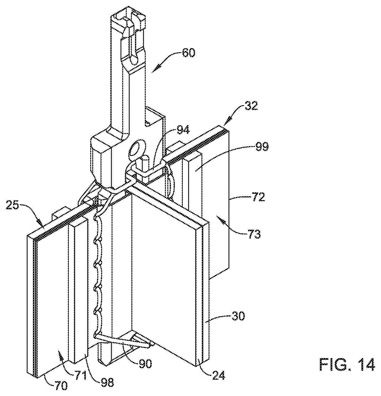
D00016

XML
uspto.report is an independent third-party trademark research tool that is not affiliated, endorsed, or sponsored by the United States Patent and Trademark Office (USPTO) or any other governmental organization. The information provided by uspto.report is based on publicly available data at the time of writing and is intended for informational purposes only.
While we strive to provide accurate and up-to-date information, we do not guarantee the accuracy, completeness, reliability, or suitability of the information displayed on this site. The use of this site is at your own risk. Any reliance you place on such information is therefore strictly at your own risk.
All official trademark data, including owner information, should be verified by visiting the official USPTO website at www.uspto.gov. This site is not intended to replace professional legal advice and should not be used as a substitute for consulting with a legal professional who is knowledgeable about trademark law.