Circular needle applier with articulating and rotating shaft
Zeiner , et al. March 9, 2
U.S. patent number 10,939,909 [Application Number 15/984,476] was granted by the patent office on 2021-03-09 for circular needle applier with articulating and rotating shaft. This patent grant is currently assigned to Ethicon LLC. The grantee listed for this patent is Ethicon LLC. Invention is credited to Wells D. Haberstich, David T. Martin, James A. Woodard, Jr., Mark S. Zeiner.


View All Diagrams
| United States Patent | 10,939,909 |
| Zeiner , et al. | March 9, 2021 |
Circular needle applier with articulating and rotating shaft
Abstract
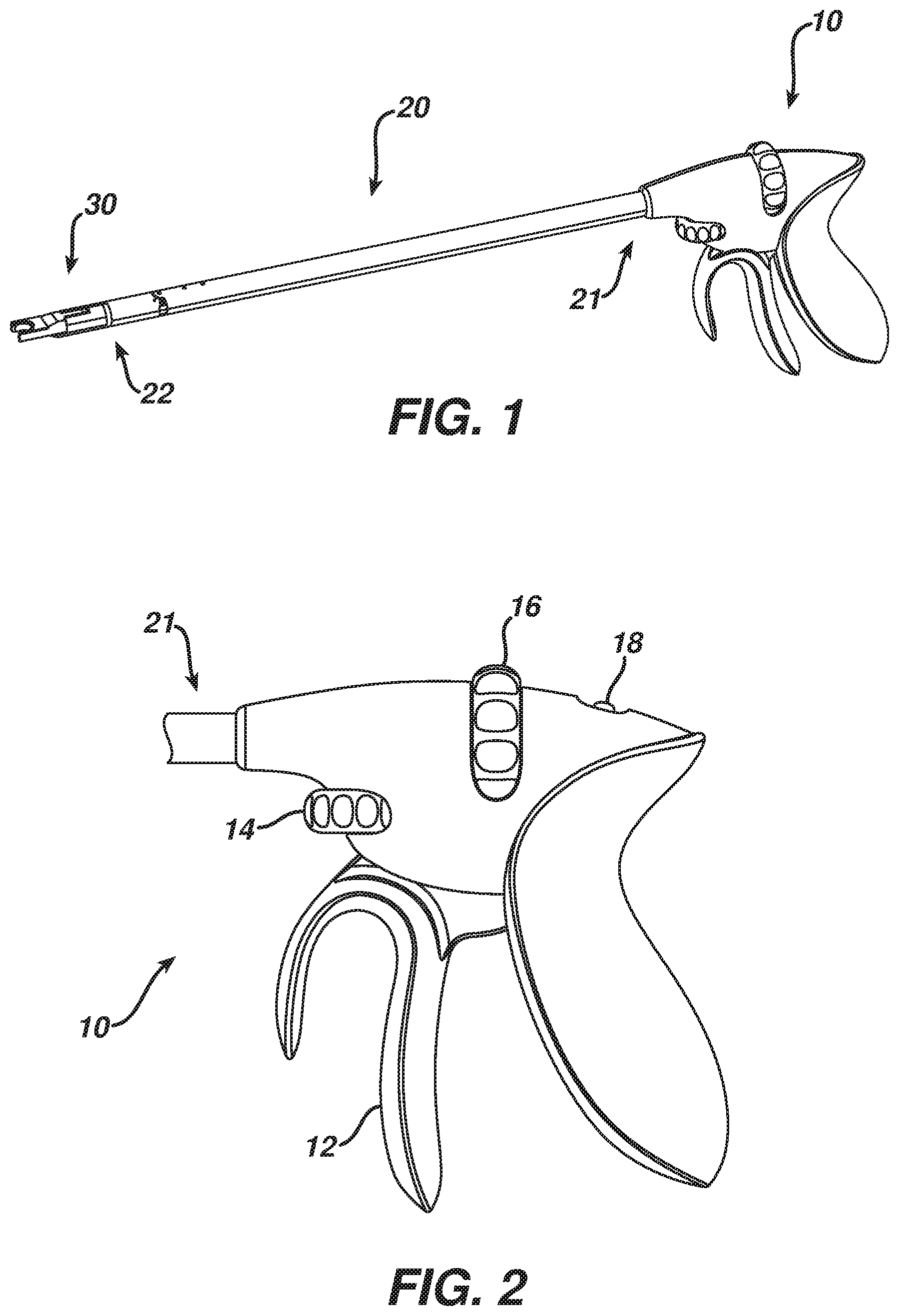
A surgical suturing device has an elongate shaft has a proximal end, a distal end, and a longitudinal axis between the proximal and distal ends. An actuator is connected to the proximal end of the elongate shaft. A circular needle applier is on the distal end of the elongate shaft. The circular needle applier has an arced needle and a needle driver operatively connected to the actuator to rotate the arced needle in a circular path. A joint is positioned between the proximal and distal ends of the elongate shaft. The joint is operatively connected to the actuator to selectively articulate the shaft. A bearing is on the shaft positioned distally of the joint. The bearing is operatively connected to the actuator to selectively rotate the circular needle applier about the longitudinal axis.
| Inventors: | Zeiner; Mark S. (Mason, OH), Haberstich; Wells D. (Loveland, OH), Martin; David T. (Milford, OH), Woodard, Jr.; James A. (Apex, NC) | ||||||||||
|---|---|---|---|---|---|---|---|---|---|---|---|
| Applicant: |
|
||||||||||
| Assignee: | Ethicon LLC (Guaynabo,
PR) |
||||||||||
| Family ID: | 1000005407958 | ||||||||||
| Appl. No.: | 15/984,476 | ||||||||||
| Filed: | May 21, 2018 |
Prior Publication Data
| Document Identifier | Publication Date | |
|---|---|---|
| US 20180263620 A1 | Sep 20, 2018 | |
Related U.S. Patent Documents
| Application Number | Filing Date | Patent Number | Issue Date | ||
|---|---|---|---|---|---|
| 15222385 | Jul 28, 2016 | 9986998 | |||
| 13832709 | Nov 12, 2016 | 9498207 | |||
| 61736682 | Dec 13, 2012 | ||||
| 61736696 | Dec 13, 2012 | ||||
| 61736678 | Dec 13, 2012 | ||||
| 61736690 | Dec 13, 2012 | ||||
| Current U.S. Class: | 1/1 |
| Current CPC Class: | A61B 17/0469 (20130101); A61B 17/0483 (20130101); A61B 17/06133 (20130101); A61B 17/0625 (20130101); A61B 17/06114 (20130101); A61B 17/0491 (20130101); A61B 17/0482 (20130101); A61B 2017/06028 (20130101); F04C 2270/0421 (20130101); A61B 2017/00473 (20130101); A61B 2017/0608 (20130101); A61B 2017/2927 (20130101); A61B 2017/0023 (20130101); A61B 17/06123 (20130101); A61B 2017/07271 (20130101) |
| Current International Class: | A61B 17/06 (20060101); A61B 17/04 (20060101); A61B 17/062 (20060101); A61B 17/00 (20060101); A61B 17/072 (20060101); A61B 17/29 (20060101) |
References Cited [Referenced By]
U.S. Patent Documents
| 919152 | April 1909 | Charles |
| 1203244 | October 1916 | Thomas |
| 1579379 | April 1926 | Marbel |
| 1822330 | September 1931 | Ainslie |
| 1884149 | October 1932 | Nullmeyer |
| 2291181 | July 1942 | Alderman |
| 3043309 | July 1962 | McCarthy |
| 3160157 | December 1964 | Chisman |
| 3168097 | February 1965 | Dormia |
| 3358676 | December 1967 | Frei et al. |
| 3598281 | August 1971 | Michael |
| 3710399 | January 1973 | Hurst |
| 3749238 | July 1973 | Taylor |
| 3815843 | June 1974 | Fortune |
| 3893448 | July 1975 | Brantigan |
| 3901244 | August 1975 | Schweizer |
| 3906217 | September 1975 | Lackore |
| 3988535 | October 1976 | Hickman et al. |
| 4027608 | June 1977 | Arbuckle |
| 4047136 | September 1977 | Satto |
| 4063561 | December 1977 | McKenna |
| 4084692 | April 1978 | Bilweis |
| 4099192 | July 1978 | Aizawa et al. |
| 4123982 | November 1978 | Bess, Jr. et al. |
| 4196836 | April 1980 | Becht |
| 4203430 | May 1980 | Takahashi |
| 4235177 | November 1980 | Arbuckle |
| 4239308 | December 1980 | Bradley |
| 4278077 | July 1981 | Mizumoto |
| 4384584 | May 1983 | Chen |
| 4406237 | September 1983 | Eguchi et al. |
| 4417532 | November 1983 | Yasukata |
| 4440171 | April 1984 | Nomoto et al. |
| 4557265 | December 1985 | Andersson |
| 4585282 | April 1986 | Bosley |
| 4597390 | July 1986 | Mulhollan et al. |
| 4624254 | November 1986 | McGarry et al. |
| 4655746 | April 1987 | Daniels et al. |
| 4880015 | November 1989 | Nierman |
| 4890614 | January 1990 | Kawada et al. |
| 4890615 | January 1990 | Caspari et al. |
| 4899746 | February 1990 | Brunk |
| 4942866 | July 1990 | Usami |
| 5020514 | June 1991 | Heckele |
| 5052402 | October 1991 | Bencini et al. |
| 5053043 | October 1991 | Gottesman et al. |
| 5131534 | July 1992 | Brown et al. |
| 5133723 | July 1992 | Li et al. |
| 5201743 | April 1993 | Haber et al. |
| 5209747 | May 1993 | Knoepfler |
| 5282806 | February 1994 | Haber et al. |
| 5286255 | February 1994 | Weber |
| 5289963 | March 1994 | McGarry et al. |
| 5306281 | April 1994 | Beurrier |
| 5308353 | May 1994 | Beurrier |
| 5308357 | May 1994 | Lichtman |
| 5312023 | May 1994 | Green et al. |
| 5314424 | May 1994 | Nicholas |
| 5318578 | June 1994 | Hasson |
| 5330502 | July 1994 | Hassler et al. |
| 5344061 | September 1994 | Crainich |
| 5351518 | October 1994 | Bogart et al. |
| 5352219 | October 1994 | Reddy |
| 5383888 | January 1995 | Zvenyatsky et al. |
| 5389103 | February 1995 | Melzer et al. |
| 5392917 | February 1995 | Alpern et al. |
| 5403347 | April 1995 | Roby et al. |
| 5403354 | April 1995 | Adams et al. |
| 5411613 | May 1995 | Rizk et al. |
| 5417203 | May 1995 | Tovey et al. |
| 5437681 | August 1995 | Meade et al. |
| 5441059 | August 1995 | Dannan |
| 5454823 | October 1995 | Richardson et al. |
| 5458609 | October 1995 | Gordon et al. |
| 5468250 | November 1995 | Paraschac et al. |
| 5470338 | November 1995 | Whitfield et al. |
| 5478344 | December 1995 | Stone et al. |
| 5478345 | December 1995 | Stone et al. |
| 5480406 | January 1996 | Nolan et al. |
| 5502698 | March 1996 | Mochizuki |
| 5507297 | April 1996 | Slater et al. |
| 5507774 | April 1996 | Holmes et al. |
| 5527321 | June 1996 | Hinchliffe |
| 5540648 | July 1996 | Yoon |
| 5540704 | July 1996 | Gordon et al. |
| 5540705 | July 1996 | Meade et al. |
| 5540706 | July 1996 | Aust et al. |
| 5549542 | August 1996 | Kovalcheck |
| 5553477 | September 1996 | Eisensmith et al. |
| 5554170 | September 1996 | Roby et al. |
| 5560532 | October 1996 | Defonzo et al. |
| 5562655 | October 1996 | Mittelstadt et al. |
| 5569301 | October 1996 | Granger et al. |
| 5571090 | November 1996 | Sherts |
| 5578052 | November 1996 | Koros et al. |
| 5591181 | January 1997 | Stone et al. |
| 5593402 | January 1997 | Patrick |
| 5593421 | January 1997 | Bauer |
| 5607450 | March 1997 | Zvenyatsky et al. |
| 5610653 | March 1997 | Abecassis |
| 5613937 | March 1997 | Garrison et al. |
| 5617952 | April 1997 | Kranendonk |
| 5618303 | April 1997 | Marlow et al. |
| 5630825 | May 1997 | De et al. |
| 5632432 | May 1997 | Schulze et al. |
| 5632746 | May 1997 | Middleman et al. |
| 5632764 | May 1997 | Beideman et al. |
| 5643295 | July 1997 | Yoon |
| 5645552 | July 1997 | Sherts |
| 5649961 | July 1997 | McGregor et al. |
| 5665096 | September 1997 | Yoon |
| 5665109 | September 1997 | Yoon |
| 5669490 | September 1997 | Colligan et al. |
| 5674229 | October 1997 | Tovey et al. |
| 5674230 | October 1997 | Tovey et al. |
| 5693071 | December 1997 | Gorecki et al. |
| 5702408 | December 1997 | Wales et al. |
| 5707379 | January 1998 | Fleenor et al. |
| 5709693 | January 1998 | Taylor |
| 5713910 | February 1998 | Gordon et al. |
| 5716326 | February 1998 | Dannan |
| 5718714 | February 1998 | Livneh |
| 5722988 | March 1998 | Weisshaupt |
| 5728107 | March 1998 | Zlock et al. |
| 5728108 | March 1998 | Griffiths et al. |
| 5728109 | March 1998 | Schulze et al. |
| 5733293 | March 1998 | Scirica et al. |
| 5741277 | April 1998 | Gordon et al. |
| 5755729 | May 1998 | De et al. |
| 5759188 | June 1998 | Yoon |
| 5762255 | June 1998 | Chrisman et al. |
| 5766186 | June 1998 | Faraz et al. |
| 5766196 | June 1998 | Griffiths |
| 5776130 | July 1998 | Buysse et al. |
| 5776186 | July 1998 | Uflacker |
| 5782748 | July 1998 | Palmer et al. |
| 5792135 | August 1998 | Madhani et al. |
| 5792151 | August 1998 | Heck et al. |
| 5792165 | August 1998 | Klieman et al. |
| 5797927 | August 1998 | Yoon |
| 5810865 | September 1998 | Koscher et al. |
| 5810877 | September 1998 | Roth et al. |
| 5814054 | September 1998 | Kortenbach et al. |
| 5814069 | September 1998 | Schulze et al. |
| 5817084 | October 1998 | Jensen |
| 5830221 | November 1998 | Stein et al. |
| 5846254 | December 1998 | Schulze et al. |
| 5860992 | January 1999 | Daniel et al. |
| 5865836 | February 1999 | Miller |
| 5871488 | February 1999 | Tovey et al. |
| 5878193 | March 1999 | Wang et al. |
| 5881615 | March 1999 | Dahl et al. |
| 5888192 | March 1999 | Heimberger |
| 5893875 | April 1999 | O'Connor et al. |
| 5897563 | April 1999 | Yoon et al. |
| 5904667 | May 1999 | Falwell |
| 5908428 | June 1999 | Scirica et al. |
| 5911727 | June 1999 | Taylor |
| 5911829 | June 1999 | Maksudian et al. |
| 5921956 | July 1999 | Grinberg et al. |
| 5928263 | July 1999 | Hoogeboom |
| 5935138 | August 1999 | McJames, II et al. |
| 5938668 | August 1999 | Scirica et al. |
| 5941430 | August 1999 | Kuwabara |
| 5944724 | August 1999 | Lizardi |
| 5947982 | September 1999 | Duran |
| 5954731 | September 1999 | Yoon |
| 5954733 | September 1999 | Yoon |
| 5976074 | November 1999 | Moriyama |
| 5980455 | November 1999 | Daniel et al. |
| 5993381 | November 1999 | Ito |
| 5993466 | November 1999 | Yoon |
| 6016905 | January 2000 | Gemma et al. |
| 6024748 | February 2000 | Manzo et al. |
| 6053908 | April 2000 | Crainich et al. |
| 6056771 | May 2000 | Proto |
| 6059719 | May 2000 | Yamamoto et al. |
| 6071289 | June 2000 | Stefanchik et al. |
| 6086601 | July 2000 | Yoon |
| 6096051 | August 2000 | Kortenbach et al. |
| 6099537 | August 2000 | Sugai et al. |
| 6126359 | October 2000 | Dittrich et al. |
| 6126666 | October 2000 | Trapp et al. |
| 6129741 | October 2000 | Wurster et al. |
| 6135385 | October 2000 | Martinez De Lahidalga |
| 6136010 | October 2000 | Modesitt et al. |
| 6138440 | October 2000 | Gemma |
| 6152934 | November 2000 | Harper et al. |
| 6159200 | December 2000 | Verdura et al. |
| 6162208 | December 2000 | Hipps |
| 6214030 | April 2001 | Matsutani et al. |
| 6231565 | May 2001 | Tovey et al. |
| 6273882 | August 2001 | Whittier et al. |
| 6309397 | October 2001 | Julian et al. |
| 6315789 | November 2001 | Cragg |
| 6322581 | November 2001 | Fukuda et al. |
| 6332888 | December 2001 | Levy et al. |
| 6332889 | December 2001 | Sancoff et al. |
| 6364888 | April 2002 | Niemeyer et al. |
| 6419688 | July 2002 | Bacher et al. |
| 6443962 | September 2002 | Gaber |
| 6454778 | September 2002 | Kortenbach |
| 6467612 | October 2002 | Rosenfeld |
| 6471172 | October 2002 | Lemke et al. |
| 6481568 | November 2002 | Cerwin et al. |
| 6533112 | March 2003 | Warnecke |
| 6589211 | July 2003 | MacLeod |
| 6595984 | July 2003 | Deguillebon |
| 6626824 | September 2003 | Ruegg et al. |
| 6635071 | October 2003 | Boche et al. |
| 6663641 | December 2003 | Kovac et al. |
| 6666875 | December 2003 | Sakurai et al. |
| 6719763 | April 2004 | Chee et al. |
| 6719764 | April 2004 | Gellman et al. |
| 6723043 | April 2004 | Kleeman et al. |
| 6743239 | June 2004 | Kuehn et al. |
| 6755843 | June 2004 | Chung et al. |
| 6770081 | August 2004 | Cooper et al. |
| 6776165 | August 2004 | Jin |
| 6783524 | August 2004 | Anderson et al. |
| 6783537 | August 2004 | Kuhr et al. |
| D496997 | October 2004 | Dycus et al. |
| 6814742 | November 2004 | Kimura et al. |
| 6827712 | December 2004 | Tovey et al. |
| 6860878 | March 2005 | Brock |
| 6869395 | March 2005 | Page et al. |
| 6884213 | April 2005 | Raz et al. |
| 6923819 | August 2005 | Meade et al. |
| 6936003 | August 2005 | Iddan |
| 6936054 | August 2005 | Chu et al. |
| 6939358 | September 2005 | Palacios et al. |
| 6942674 | September 2005 | Belef et al. |
| 6955643 | October 2005 | Gellman et al. |
| 6986738 | January 2006 | Glukhovsky et al. |
| 6994708 | February 2006 | Manzo |
| 7004951 | February 2006 | Gibbens et al. |
| 7022085 | April 2006 | Cooke et al. |
| 7039453 | May 2006 | Mullick et al. |
| 7041111 | May 2006 | Chu et al. |
| 7042184 | May 2006 | Oleynikov et al. |
| 7066879 | June 2006 | Fowler et al. |
| 7083579 | August 2006 | Yokoi et al. |
| 7122028 | October 2006 | Looper et al. |
| 7125403 | October 2006 | Julian et al. |
| 7131979 | November 2006 | DiCarlo et al. |
| 7144401 | December 2006 | Yamamoto et al. |
| 7166116 | January 2007 | Lizardi et al. |
| 7169104 | January 2007 | Ueda et al. |
| 7199545 | April 2007 | Oleynikov et al. |
| 7211094 | May 2007 | Gannoe et al. |
| 7232447 | June 2007 | Gellman et al. |
| 7235087 | June 2007 | Modesitt et al. |
| 7241290 | July 2007 | Doyle et al. |
| 7278563 | October 2007 | Green |
| 7297142 | November 2007 | Brock |
| 7331967 | February 2008 | Lee et al. |
| 7338504 | March 2008 | Gibbens et al. |
| 7429259 | September 2008 | Cadeddu et al. |
| 7442198 | October 2008 | Gellman et al. |
| 7448993 | November 2008 | Yokoi et al. |
| 7491166 | February 2009 | Ueno et al. |
| 7520382 | April 2009 | Kennedy et al. |
| 7524320 | April 2009 | Tierney et al. |
| 7527418 | May 2009 | Lin et al. |
| D594983 | June 2009 | Price et al. |
| 7559887 | July 2009 | Dannan |
| 7566331 | July 2009 | Looper et al. |
| 7582096 | September 2009 | Gellman et al. |
| 7588583 | September 2009 | Hamilton et al. |
| 7604611 | October 2009 | Falwell et al. |
| 7604642 | October 2009 | Brock |
| 7615060 | November 2009 | Stokes et al. |
| 7628796 | December 2009 | Shelton, IV et al. |
| 7637369 | December 2009 | Kennedy et al. |
| 7651471 | January 2010 | Yokoi et al. |
| 7666181 | February 2010 | Abou |
| 7666194 | February 2010 | Field et al. |
| 7678043 | March 2010 | Gilad |
| 7686831 | March 2010 | Stokes et al. |
| 7691095 | April 2010 | Bednarek et al. |
| 7691098 | April 2010 | Wallace et al. |
| 7691103 | April 2010 | Fernandez et al. |
| 7691126 | April 2010 | Bacher |
| 7699835 | April 2010 | Lee et al. |
| 7699860 | April 2010 | Huitema et al. |
| 7703653 | April 2010 | Shah et al. |
| 7722599 | May 2010 | Julian et al. |
| D618797 | June 2010 | Price et al. |
| 7763036 | July 2010 | Stokes et al. |
| 7766925 | August 2010 | Stokes et al. |
| 7770365 | August 2010 | Enriquez, III et al. |
| 7806891 | October 2010 | Nowlin et al. |
| 7815654 | October 2010 | Chu et al. |
| 7824401 | November 2010 | Manzo et al. |
| 7828812 | November 2010 | Stokes et al. |
| 7833235 | November 2010 | Chu et al. |
| 7833236 | November 2010 | Stokes et al. |
| 7842048 | November 2010 | Ma |
| 7846169 | December 2010 | Shelton, IV et al. |
| 7857812 | December 2010 | Dycus et al. |
| 7862553 | January 2011 | Ewaschuk |
| 7862572 | January 2011 | Meade |
| 7862575 | January 2011 | Tal |
| 7862582 | January 2011 | Ortiz et al. |
| D631965 | February 2011 | Price et al. |
| 7887554 | February 2011 | Stokes et al. |
| 7891485 | February 2011 | Prescott |
| 7894561 | February 2011 | Buchanan |
| 7894882 | February 2011 | Mullick et al. |
| 7896890 | March 2011 | Ortiz et al. |
| 7901398 | March 2011 | Stanczak et al. |
| 7909220 | March 2011 | Viola |
| 7922063 | April 2011 | Zemlok et al. |
| 7935128 | May 2011 | Rioux et al. |
| 7942886 | May 2011 | Alvarado |
| 7947052 | May 2011 | Baxter et al. |
| 7976553 | July 2011 | Shelton, IV et al. |
| 7976555 | July 2011 | Meade et al. |
| 7993354 | August 2011 | Brecher |
| 8012154 | September 2011 | Livneh |
| 8012161 | September 2011 | Primavera et al. |
| 8016840 | September 2011 | Takemoto et al. |
| 8021358 | September 2011 | Doyle et al. |
| 8021375 | September 2011 | Aldrich et al. |
| 8038612 | October 2011 | Paz |
| 8048092 | November 2011 | Modesitt et al. |
| 8052636 | November 2011 | Moll et al. |
| 8057386 | November 2011 | Aznoian et al. |
| 8057502 | November 2011 | Maliglowka et al. |
| 8066737 | November 2011 | Meade et al. |
| 8070759 | December 2011 | Stefanchik |
| 8088062 | January 2012 | Zwolinski |
| 8100922 | January 2012 | Griffith |
| 8114098 | February 2012 | Kimura et al. |
| 8118820 | February 2012 | Stokes et al. |
| 8123762 | February 2012 | Chu et al. |
| 8123764 | February 2012 | Meade |
| 8128643 | March 2012 | Aranyi |
| 8133254 | March 2012 | Dumbauld et al. |
| 8136656 | March 2012 | Kennedy et al. |
| 8172858 | May 2012 | Park et al. |
| 8182414 | May 2012 | Handa et al. |
| 8187166 | May 2012 | Kuth et al. |
| 8187288 | May 2012 | Chu et al. |
| D661801 | June 2012 | Price et al. |
| D661802 | June 2012 | Price et al. |
| D661803 | June 2012 | Price et al. |
| D661804 | June 2012 | Price et al. |
| 8196739 | June 2012 | Kirsch |
| 8201721 | June 2012 | Zemlok et al. |
| 8206284 | June 2012 | Aznoian et al. |
| 8211143 | July 2012 | Stefanchik et al. |
| 8236010 | August 2012 | Ortiz et al. |
| 8236013 | August 2012 | Chu |
| 8241320 | August 2012 | Lyons et al. |
| 8246637 | August 2012 | Viola et al. |
| 8252008 | August 2012 | Ma |
| 8256613 | September 2012 | Kirsch et al. |
| 8257369 | September 2012 | Gellman et al. |
| 8257371 | September 2012 | Hamilton et al. |
| 8292067 | October 2012 | Chowaniec et al. |
| 8292906 | October 2012 | Taylor et al. |
| 8293094 | October 2012 | Iyengar et al. |
| 8307978 | November 2012 | Kirsch et al. |
| 8328822 | December 2012 | Huitema et al. |
| 8333776 | December 2012 | Cheng et al. |
| 8353897 | January 2013 | Doyle et al. |
| 8361072 | January 2013 | Dumbauld et al. |
| 8361089 | January 2013 | Chu |
| 8366725 | February 2013 | Chu et al. |
| 8372090 | February 2013 | Wingardner et al. |
| 8377044 | February 2013 | Coe et al. |
| 8397335 | March 2013 | Gordin et al. |
| 8398544 | March 2013 | Altamirano |
| 8398660 | March 2013 | Chu et al. |
| 8409076 | April 2013 | Pang et al. |
| 8460320 | June 2013 | Hirzel |
| 8469973 | June 2013 | Meade et al. |
| D685907 | July 2013 | Park et al. |
| 8474522 | July 2013 | Lynde et al. |
| 8475361 | July 2013 | Barlow et al. |
| 8490713 | July 2013 | Furnish et al. |
| D687549 | August 2013 | Johnson et al. |
| 8500756 | August 2013 | Papa et al. |
| 8512243 | August 2013 | Stafford et al. |
| 8518024 | August 2013 | Williams et al. |
| 8518058 | August 2013 | Gellman et al. |
| 8545519 | October 2013 | Aguirre et al. |
| 8551122 | October 2013 | Lau |
| 8556069 | October 2013 | Kirsch |
| 8562630 | October 2013 | Campbell |
| 8568428 | October 2013 | Mcclurg et al. |
| 8579918 | November 2013 | Whitfield et al. |
| 8603089 | December 2013 | Viola |
| 8616431 | December 2013 | Timm et al. |
| 8623027 | January 2014 | Price et al. |
| 8623048 | January 2014 | Meade et al. |
| 8627816 | January 2014 | Edwards et al. |
| 8636648 | January 2014 | Gazdzinski |
| 8641728 | February 2014 | Stokes et al. |
| D700699 | March 2014 | O'Leary et al. |
| 8663253 | March 2014 | Saliman |
| 8679136 | March 2014 | Mitelberg |
| 8696687 | April 2014 | Gellman et al. |
| 8702729 | April 2014 | Chu |
| 8702732 | April 2014 | Woodard, Jr. et al. |
| 8709021 | April 2014 | Chu et al. |
| 8721539 | May 2014 | Shohat et al. |
| 8746445 | June 2014 | Kennedy et al. |
| 8747304 | June 2014 | Zeiner |
| 8758391 | June 2014 | Swayze et al. |
| D709194 | July 2014 | Miller et al. |
| 8764735 | July 2014 | Coe et al. |
| 8771295 | July 2014 | Chu |
| 8821518 | September 2014 | Saliman |
| 8821519 | September 2014 | Meade |
| 8833549 | September 2014 | Kirsch |
| 8845661 | September 2014 | D'Arcangelo et al. |
| 8858572 | October 2014 | Klundt et al. |
| D716945 | November 2014 | Miller et al. |
| 8906041 | December 2014 | Chu et al. |
| 8906043 | December 2014 | Woodard, Jr. et al. |
| 8910846 | December 2014 | Viola |
| 8920440 | December 2014 | Mcclurg et al. |
| 8920441 | December 2014 | Saliman |
| 8925783 | January 2015 | Zemlok et al. |
| 8939997 | January 2015 | Martinez et al. |
| 8968337 | March 2015 | Whitfield et al. |
| 8968340 | March 2015 | Chowaniec et al. |
| 8979891 | March 2015 | Mclawhorn et al. |
| 9060769 | June 2015 | Coleman et al. |
| 9072535 | July 2015 | Shelton, IV et al. |
| 9078649 | July 2015 | Gellman et al. |
| 9113861 | August 2015 | Martin et al. |
| 9113876 | August 2015 | Zemlok et al. |
| 9125644 | September 2015 | Lane et al. |
| 9125645 | September 2015 | Martin et al. |
| 9125646 | September 2015 | Woodard, Jr. et al. |
| 9144483 | September 2015 | Chu et al. |
| 9168037 | October 2015 | Woodard, Jr. et al. |
| 9173655 | November 2015 | Martin |
| D745146 | December 2015 | Hess et al. |
| 9220496 | December 2015 | Martin et al. |
| 9241712 | January 2016 | Zemlok et al. |
| 9247938 | February 2016 | Martin et al. |
| 9271749 | March 2016 | Kiapour et al. |
| 9277916 | March 2016 | Martin et al. |
| 9289206 | March 2016 | Hess et al. |
| D754856 | April 2016 | Martin et al. |
| 9314292 | April 2016 | Trees et al. |
| 9351754 | May 2016 | Vakharia et al. |
| 9357998 | June 2016 | Martin et al. |
| 9370354 | June 2016 | Martin et al. |
| 9375212 | June 2016 | White et al. |
| 9398905 | July 2016 | Martin et al. |
| 9402626 | August 2016 | Ortiz et al. |
| 9427226 | August 2016 | Martin et al. |
| 9427227 | August 2016 | Martin et al. |
| 9427228 | August 2016 | Hart et al. |
| 9451937 | September 2016 | Parihar et al. |
| 9451946 | September 2016 | Woodard, Jr. et al. |
| 9474522 | October 2016 | Deck et al. |
| D771811 | November 2016 | Reyhan et al. |
| 9486126 | November 2016 | West et al. |
| 9486209 | November 2016 | Martin et al. |
| 9498207 | November 2016 | Martin et al. |
| 9526495 | December 2016 | Martin et al. |
| 9545191 | January 2017 | Stokes et al. |
| 9554793 | January 2017 | Lane et al. |
| 9585655 | March 2017 | Woodard, Jr. et al. |
| 9675340 | June 2017 | Sniffin et al. |
| 9724087 | August 2017 | Berry et al. |
| 9833232 | December 2017 | Woodard, Jr. et al. |
| 9839419 | December 2017 | Deck et al. |
| 9888914 | February 2018 | Martin et al. |
| 2001/0025134 | September 2001 | Bon et al. |
| 2001/0027312 | October 2001 | Bacher et al. |
| 2002/0128645 | September 2002 | Messerly |
| 2002/0138084 | September 2002 | Weber |
| 2002/0177843 | November 2002 | Anderson et al. |
| 2002/0193809 | December 2002 | Meade |
| 2003/0083674 | May 2003 | Gibbens et al. |
| 2003/0114731 | June 2003 | Cadeddu et al. |
| 2003/0120272 | June 2003 | Schneider et al. |
| 2003/0204195 | October 2003 | Keane et al. |
| 2003/0208100 | November 2003 | Levy |
| 2003/0233104 | December 2003 | Gellman et al. |
| 2004/0015177 | January 2004 | Chu et al. |
| 2004/0050721 | March 2004 | Roby et al. |
| 2004/0093039 | May 2004 | Schumert |
| 2004/0097830 | May 2004 | Cooke et al. |
| 2004/0122472 | June 2004 | Collier et al. |
| 2004/0152941 | August 2004 | Asmus et al. |
| 2004/0172047 | September 2004 | Gellman et al. |
| 2004/0260314 | December 2004 | Lizardi et al. |
| 2004/0267254 | December 2004 | Manzo et al. |
| 2005/0015101 | January 2005 | Gibbens et al. |
| 2005/0033354 | February 2005 | Montalvo et al. |
| 2005/0085851 | April 2005 | Fiehler et al. |
| 2005/0119640 | June 2005 | Sverduk et al. |
| 2005/0131457 | June 2005 | Douglas et al. |
| 2005/0216038 | September 2005 | Meade et al. |
| 2005/0250984 | November 2005 | Lam et al. |
| 2005/0272972 | December 2005 | Iddan |
| 2005/0272974 | December 2005 | Iddan |
| 2005/0273139 | December 2005 | Krauss et al. |
| 2005/0288555 | December 2005 | Binmoeller |
| 2006/0036232 | February 2006 | Primavera et al. |
| 2006/0047309 | March 2006 | Cichocki, Jr. |
| 2006/0069396 | March 2006 | Meade |
| 2006/0079933 | April 2006 | Hushka et al. |
| 2006/0111732 | May 2006 | Gibbens et al. |
| 2006/0173491 | August 2006 | Meade et al. |
| 2006/0184161 | August 2006 | Maahs et al. |
| 2006/0190035 | August 2006 | Hushka et al. |
| 2006/0258905 | November 2006 | Kaji et al. |
| 2006/0259073 | November 2006 | Miyamoto et al. |
| 2006/0281970 | December 2006 | Stokes et al. |
| 2006/0282090 | December 2006 | Stokes et al. |
| 2006/0282091 | December 2006 | Shelton, IV et al. |
| 2006/0282092 | December 2006 | Stokes et al. |
| 2006/0282093 | December 2006 | Shelton, IV et al. |
| 2006/0282094 | December 2006 | Stokes et al. |
| 2006/0282095 | December 2006 | Stokes et al. |
| 2006/0282096 | December 2006 | Papa et al. |
| 2006/0282097 | December 2006 | Ortiz et al. |
| 2006/0282098 | December 2006 | Shelton, IV |
| 2006/0282099 | December 2006 | Stokes et al. |
| 2007/0010709 | January 2007 | Reinschke |
| 2007/0049966 | March 2007 | Bonadio et al. |
| 2007/0073247 | March 2007 | Ewaschuk |
| 2007/0088372 | April 2007 | Gellman et al. |
| 2007/0123748 | May 2007 | Meglan |
| 2007/0162052 | July 2007 | Hashimoto et al. |
| 2007/0173864 | July 2007 | Chu et al. |
| 2007/0239176 | October 2007 | Stokes et al. |
| 2007/0239177 | October 2007 | Stokes et al. |
| 2007/0250113 | October 2007 | Hegeman et al. |
| 2007/0256945 | November 2007 | Kennedy et al. |
| 2007/0265502 | November 2007 | Minosawa et al. |
| 2007/0270651 | November 2007 | Gilad et al. |
| 2008/0004656 | January 2008 | Livneh |
| 2008/0015413 | January 2008 | Barlow et al. |
| 2008/0045003 | February 2008 | Lee et al. |
| 2008/0071296 | March 2008 | Klundt et al. |
| 2008/0091220 | April 2008 | Chu |
| 2008/0103357 | May 2008 | Zeiner et al. |
| 2008/0109015 | May 2008 | Chu et al. |
| 2008/0132919 | June 2008 | Chui et al. |
| 2008/0142005 | June 2008 | Schnell |
| 2008/0154299 | June 2008 | Livneh |
| 2008/0177134 | July 2008 | Miyamoto et al. |
| 2008/0208246 | August 2008 | Livneh |
| 2008/0228204 | September 2008 | Hamilton et al. |
| 2008/0242939 | October 2008 | Johnston |
| 2008/0243106 | October 2008 | Coe et al. |
| 2008/0243146 | October 2008 | Sloan et al. |
| 2008/0255590 | October 2008 | Meade et al. |
| 2009/0005638 | January 2009 | Zwolinski |
| 2009/0024145 | January 2009 | Meade et al. |
| 2009/0084826 | April 2009 | Shah et al. |
| 2009/0088792 | April 2009 | Hoell, Jr. et al. |
| 2009/0105750 | April 2009 | Price et al. |
| 2009/0108048 | April 2009 | Zemlok et al. |
| 2009/0138029 | May 2009 | Saliman et al. |
| 2009/0171147 | July 2009 | Lee et al. |
| 2009/0205987 | August 2009 | Kennedy et al. |
| 2009/0209946 | August 2009 | Swayze et al. |
| 2009/0209980 | August 2009 | Harris |
| 2009/0210006 | August 2009 | Cohen et al. |
| 2009/0248041 | October 2009 | Williams et al. |
| 2009/0259092 | October 2009 | Ogdahl et al. |
| 2009/0264904 | October 2009 | Aldrich et al. |
| 2009/0287226 | November 2009 | Gellman et al. |
| 2009/0312772 | December 2009 | Chu |
| 2010/0010512 | January 2010 | Taylor et al. |
| 2010/0016866 | January 2010 | Meade et al. |
| 2010/0016870 | January 2010 | Campbell |
| 2010/0023024 | January 2010 | Zeiner et al. |
| 2010/0036415 | February 2010 | Cabezas |
| 2010/0042116 | February 2010 | Chui et al. |
| 2010/0063519 | March 2010 | Park et al. |
| 2010/0078335 | April 2010 | Iyengar et al. |
| 2010/0078336 | April 2010 | Reyhan et al. |
| 2010/0100125 | April 2010 | Mahadevan |
| 2010/0152751 | June 2010 | Meade |
| 2010/0198248 | August 2010 | Vakharia |
| 2010/0230300 | September 2010 | Hunter et al. |
| 2010/0242116 | September 2010 | Choo et al. |
| 2010/0249700 | September 2010 | Spivey |
| 2010/0274265 | October 2010 | Wingardner et al. |
| 2010/0307934 | December 2010 | Chowaniec et al. |
| 2011/0028999 | February 2011 | Chu et al. |
| 2011/0040308 | February 2011 | Cabrera et al. |
| 2011/0040322 | February 2011 | Major |
| 2011/0042244 | February 2011 | Kirsch |
| 2011/0042245 | February 2011 | Mcclurg et al. |
| 2011/0046642 | February 2011 | Mcclurg et al. |
| 2011/0046645 | February 2011 | Mcclurg et al. |
| 2011/0046667 | February 2011 | Culligan et al. |
| 2011/0060349 | March 2011 | Cheng et al. |
| 2011/0060352 | March 2011 | Chu et al. |
| 2011/0082476 | April 2011 | Furnish et al. |
| 2011/0087224 | April 2011 | Cadeddu et al. |
| 2011/0087265 | April 2011 | Nobis et al. |
| 2011/0087266 | April 2011 | Conlon et al. |
| 2011/0087267 | April 2011 | Spivey et al. |
| 2011/0208007 | August 2011 | Shohat et al. |
| 2011/0218557 | September 2011 | Saliman |
| 2011/0230869 | September 2011 | Altamirano et al. |
| 2011/0278344 | November 2011 | Zemlok et al. |
| 2011/0288560 | November 2011 | Shohat et al. |
| 2011/0288582 | November 2011 | Meade et al. |
| 2011/0295278 | December 2011 | Meade et al. |
| 2011/0313433 | December 2011 | Woodard, Jr. et al. |
| 2012/0004672 | January 2012 | Giap et al. |
| 2012/0016391 | January 2012 | Aguirre et al. |
| 2012/0029534 | February 2012 | Whitfield |
| 2012/0035626 | February 2012 | Chu |
| 2012/0041456 | February 2012 | Gellman et al. |
| 2012/0055828 | March 2012 | Kennedy et al. |
| 2012/0059396 | March 2012 | Harris et al. |
| 2012/0078243 | March 2012 | Worrell et al. |
| 2012/0078290 | March 2012 | Nobis et al. |
| 2012/0078291 | March 2012 | Nobis et al. |
| 2012/0083778 | April 2012 | Mcgaffigan et al. |
| 2012/0083826 | April 2012 | Chao et al. |
| 2012/0109160 | May 2012 | Martinez et al. |
| 2012/0109163 | May 2012 | Chu et al. |
| 2012/0123471 | May 2012 | Woodard, Jr. et al. |
| 2012/0130404 | May 2012 | Meade et al. |
| 2012/0143223 | June 2012 | Woodard, Jr. et al. |
| 2012/0143248 | June 2012 | Brecher |
| 2012/0150199 | June 2012 | Woodard, Jr. et al. |
| 2012/0165837 | June 2012 | Belman |
| 2012/0165838 | June 2012 | Kobylewski et al. |
| 2012/0165863 | June 2012 | Mclawhorn et al. |
| 2012/0172897 | July 2012 | Mcclurg et al. |
| 2012/0184946 | July 2012 | Price et al. |
| 2012/0215234 | August 2012 | Chowaniec et al. |
| 2012/0217184 | August 2012 | Edwards et al. |
| 2012/0220832 | August 2012 | Nakade et al. |
| 2012/0220989 | August 2012 | Zemlok et al. |
| 2012/0226292 | September 2012 | Hirzel |
| 2012/0228163 | September 2012 | Kirsch |
| 2012/0232567 | September 2012 | Fairneny |
| 2012/0239062 | September 2012 | Saliman |
| 2012/0259325 | October 2012 | Houser et al. |
| 2012/0283748 | November 2012 | Ortiz et al. |
| 2012/0283750 | November 2012 | Saliman et al. |
| 2012/0283755 | November 2012 | Gellman et al. |
| 2012/0289773 | November 2012 | Joshi et al. |
| 2012/0289975 | November 2012 | Martin et al. |
| 2012/0290005 | November 2012 | Martin et al. |
| 2012/0316575 | December 2012 | Farin et al. |
| 2013/0023924 | January 2013 | Mueller |
| 2013/0035631 | February 2013 | Spilgies et al. |
| 2013/0041388 | February 2013 | Lane |
| 2013/0085337 | April 2013 | Hess et al. |
| 2013/0123782 | May 2013 | Trees et al. |
| 2013/0158593 | June 2013 | Kiapour et al. |
| 2013/0211196 | August 2013 | Belson et al. |
| 2013/0245647 | September 2013 | Martin et al. |
| 2013/0245648 | September 2013 | Martin et al. |
| 2013/0282027 | October 2013 | Woodard, Jr. et al. |
| 2013/0282031 | October 2013 | Woodard, Jr. et al. |
| 2013/0296889 | November 2013 | Tong et al. |
| 2013/0331866 | December 2013 | Gellman et al. |
| 2014/0005474 | January 2014 | Farin et al. |
| 2014/0005681 | January 2014 | Gee et al. |
| 2014/0005704 | January 2014 | Vakharia et al. |
| 2014/0039527 | February 2014 | Avelar et al. |
| 2014/0052159 | February 2014 | Teague et al. |
| 2014/0066711 | March 2014 | Farin et al. |
| 2014/0088569 | March 2014 | Parihar et al. |
| 2014/0088621 | March 2014 | Krieger |
| 2014/0088637 | March 2014 | Parihar et al. |
| 2014/0088638 | March 2014 | Parihar |
| 2014/0131249 | May 2014 | Hart et al. |
| 2014/0166514 | June 2014 | Martin et al. |
| 2014/0171970 | June 2014 | Martin et al. |
| 2014/0171971 | June 2014 | Martin et al. |
| 2014/0171972 | June 2014 | Martin et al. |
| 2014/0171975 | June 2014 | Martin et al. |
| 2014/0171976 | June 2014 | Martin et al. |
| 2014/0171977 | June 2014 | Martin et al. |
| 2014/0171978 | June 2014 | Martin |
| 2014/0171979 | June 2014 | Martin et al. |
| 2014/0172015 | June 2014 | Martin |
| 2014/0228865 | August 2014 | Weisel et al. |
| 2014/0276989 | September 2014 | Lane et al. |
| 2014/0305988 | October 2014 | Boudreaux et al. |
| 2015/0090764 | April 2015 | Zemlok et al. |
| 2015/0090765 | April 2015 | Hess et al. |
| 2015/0127024 | May 2015 | Berry et al. |
| 2015/0133967 | May 2015 | Martin |
| 2015/0142018 | May 2015 | Sniffin et al. |
| 2015/0142020 | May 2015 | Woodard, Jr. et al. |
| 2015/0327857 | November 2015 | Zemlok et al. |
| 2015/0351744 | December 2015 | Deck et al. |
| 2015/0351745 | December 2015 | Mumaw et al. |
| 2015/0351746 | December 2015 | Martin et al. |
| 2015/0351747 | December 2015 | Martin et al. |
| 2015/0351748 | December 2015 | White et al. |
| 2015/0351749 | December 2015 | Martin et al. |
| 2015/0351756 | December 2015 | Martin et al. |
| 2016/0120740 | May 2016 | Rawls-Meehan |
| 2016/0249945 | September 2016 | Shelton, IV et al. |
| 2016/0331374 | November 2016 | Martin et al. |
| 2016/0345958 | December 2016 | Martin et al. |
| 2016/0346827 | December 2016 | Martin et al. |
| 2016/0361055 | December 2016 | Martin et al. |
| 2016/0367238 | December 2016 | Deck et al. |
| 2016/0367240 | December 2016 | Shelton, IV et al. |
| 2016/0367243 | December 2016 | Martin et al. |
| 2017/0112487 | April 2017 | Martin et al. |
| 2017/0112489 | April 2017 | Shelton, IV et al. |
| 101243985 | Aug 2008 | CN | |||
| 101264027 | Sep 2008 | CN | |||
| 201899530 | Jul 2011 | CN | |||
| 102551825 | Jul 2012 | CN | |||
| 202426582 | Sep 2012 | CN | |||
| 4310315 | Oct 1993 | DE | |||
| 4300307 | Jul 1994 | DE | |||
| 10149421 | Apr 2003 | DE | |||
| 0674875 | Oct 1995 | EP | |||
| 0724861 | Aug 1996 | EP | |||
| 0739184 | Sep 1998 | EP | |||
| 1707128 | Oct 2006 | EP | |||
| 1791476 | Jun 2007 | EP | |||
| 1839591 | Oct 2007 | EP | |||
| 2055243 | May 2009 | EP | |||
| 2292157 | Mar 2011 | EP | |||
| 2308391 | Apr 2011 | EP | |||
| 2792308 | Oct 2014 | EP | |||
| 2540377 | Aug 1984 | FR | |||
| 190818602 | Sep 1909 | GB | |||
| 2389313 | Dec 2003 | GB | |||
| S55151956 | Nov 1980 | JP | |||
| 2005261734 | Sep 2005 | JP | |||
| 2013146613 | Aug 2013 | JP | |||
| WO-9519149 | Jul 1995 | WO | |||
| WO-9722300 | Jun 1997 | WO | |||
| WO-9727807 | Aug 1997 | WO | |||
| WO-9729694 | Aug 1997 | WO | |||
| WO-9912482 | Mar 1999 | WO | |||
| WO-9940850 | Aug 1999 | WO | |||
| WO-9947050 | Sep 1999 | WO | |||
| WO-0112084 | Feb 2001 | WO | |||
| WO-02102226 | Dec 2002 | WO | |||
| WO-03028541 | Apr 2003 | WO | |||
| WO-03063712 | Aug 2003 | WO | |||
| WO-2004012606 | Feb 2004 | WO | |||
| WO-2004021894 | Mar 2004 | WO | |||
| WO-2004086986 | Oct 2004 | WO | |||
| WO-2006034209 | Mar 2006 | WO | |||
| WO-2007089603 | Aug 2007 | WO | |||
| WO-2008045333 | Apr 2008 | WO | |||
| WO-2008045376 | Apr 2008 | WO | |||
| WO-2008081474 | Jul 2008 | WO | |||
| WO-2008147555 | Dec 2008 | WO | |||
| WO-2008150773 | Dec 2008 | WO | |||
| WO-2010031064 | Mar 2010 | WO | |||
| WO-2010062380 | Jun 2010 | WO | |||
| WO-2010114634 | Oct 2010 | WO | |||
| WO-2010127274 | Nov 2010 | WO | |||
| WO-2011044353 | Apr 2011 | WO | |||
| WO-2011089565 | Jul 2011 | WO | |||
| WO-2011156733 | Dec 2011 | WO | |||
| WO-2012029689 | Mar 2012 | WO | |||
| WO-2012040183 | Mar 2012 | WO | |||
| WO-2012044998 | Apr 2012 | WO | |||
| WO-2012068002 | May 2012 | WO | |||
| WO-2012088232 | Jun 2012 | WO | |||
| WO-2012112622 | Aug 2012 | WO | |||
| WO-2012112622 | Nov 2012 | WO | |||
| WO-2013007764 | Jan 2013 | WO | |||
| WO-2013048963 | Apr 2013 | WO | |||
| WO-2013142487 | Sep 2013 | WO | |||
| WO-2013158622 | Oct 2013 | WO | |||
| WO-2013167885 | Nov 2013 | WO | |||
| WO-2014052177 | Apr 2014 | WO | |||
| WO-2014147619 | Sep 2014 | WO | |||
| WO-2014162434 | Oct 2014 | WO | |||
Other References
|
Co-Pending U.S. Appl. No. 12/413,479, filed Mar. 27, 2009. cited by applicant . Co-Pending U.S. Appl. No. 12/576,514, filed Oct. 9, 2009, (Now Issued U.S. Pat. No. 8,623,011). cited by applicant . Co-Pending U.S. Appl. No. 12/576,529, filed Oct. 9, 2009. cited by applicant . Co-Pending U.S. Appl. No. 12/576,546, filed Oct. 9, 2009. cited by applicant . Co-Pending U.S. Appl. No. 12/576,565, filed Oct. 9, 2009. cited by applicant . Co-Pending U.S. Appl. No. 12/576,578, filed Oct. 9, 2009. cited by applicant . Co-Pending U.S. Appl. No. 12/617,998, filed Nov. 13, 2009 (Now US 2011/0115891). cited by applicant . Co-Pending U.S. Appl. No. 12/873,829, filed Sep. 1, 2010. cited by applicant . Co-Pending U.S. Appl. No. 12/873,845, filed Sep. 1, 2010. cited by applicant . Co-Pending U.S. Appl. No. 12/879,310, filed Sep 10, 2010, (Now 2012/0065627). cited by applicant . Co-Pending U.S. Appl. No. 12/889,454, filed Sep. 24, 2010. cited by applicant . Co-Pending U.S. Appl. No. 12/889,458, filed Sep. 24, 2010. cited by applicant . Co-Pending U.S. Appl. No. 12/900,132, filed Oct. 7, 2010, (Now US 2012/0089093). cited by applicant . Co-Pending U.S. Appl. No. 12/902,531, filed Oct. 12, 2010, (Now US 2012/0088965). cited by applicant . Co-Pending U.S. Appl. No. 12/904,280, filed Oct. 14, 2010, (Now US 2012/0095298). cited by applicant . Co-Pending U.S. Appl. No. 13/249,790, filed Sep. 30, 2011. cited by applicant . Co-Pending U.S. Appl. No. 13/627,177, filed Sep. 26, 2012. cited by applicant . Co-Pending U.S. Appl. No. 13/627,192, filed Sep. 26, 2012. cited by applicant . Co-Pending U.S. Appl. No. 13/627,211, filed Sep. 26, 2012. cited by applicant . Co-Pending U.S. Appl. No. 13/779,211, filed Feb. 27, 2013. cited by applicant . Co-Pending U.S. Appl. No. 13/779,235, filed Feb. 27, 2013. cited by applicant . Co-Pending U.S. Appl. No. 13/779,254, filed Feb. 27, 2013. cited by applicant . Co-Pending U.S. Appl. No. 13/832,496, filed Mar. 15, 2013. cited by applicant . Co-Pending U.S. Appl. No. 14/302,734, filed Jun. 12, 2014. cited by applicant . Co-Pending U.S. Appl. No. 14/557,588, filed Dec. 2, 2014. cited by applicant . Co-Pending U.S. Appl. No. 14/840,779, filed Aug. 31, 2015. cited by applicant . Co-pending U.S. Appl. No. 13/449,494, filed Apr. 18, 2012 on behalf of Ethicon Endo-Surgery. cited by applicant . Co-pending U.S. Appl. No. 13/792,947, filed Mar. 11, 2013 on behalf of Ethicon Endo-Surgery, Inc., 64 pages. cited by applicant . Co-pending U.S. Appl. No. 13/792,976, filed Mar. 11, 2013 on behalf of Ethicon Endo-Surgery, Inc., 58 pages. cited by applicant . Co-pending U.S. Appl. No. 13/793,048, filed Mar. 11, 2013 on behalf of Ethicon Endo-Surgery, Inc., 62 pages. cited by applicant . Co-pending U.S. Appl. No. 13/832,595, filed Mar. 15, 2013 on behalf of Ethicon Endo-Surgery, Inc., 62 pages. cited by applicant . Co-pending U.S. Appl. No. 13/832,660, filed Mar. 15, 2013 on behalf of Ethicon Endo-Surgery, 63 pages. cited by applicant . Co-pending U.S. Appl. No. 13/832,709, filed Mar. 15, 2013 on behalf of Ethicon Endo-Surgery, LLC, 63 pages. cited by applicant . Co-pending U.S. Appl. No. 13/832,786, filed Mar. 15, 2013 on behalf of Ethicon Endo-Surgery, Inc., 62 pages. cited by applicant . Co-pending U.S. Appl. No. 13/832,816, filed Mar. 15, 2013 on behalf of Ethicon Endo-Surgery, LLC , 62 pages. cited by applicant . Co-pending U.S. Appl. No. 13/832,867, filed Mar. 15, 2013 on behalf of Ethicon Endo-Surgery, Inc., 62 pages. cited by applicant . Co-pending U.S. Appl. No. 13/832,897, filed Mar. 15, 2013 on behalf of Ethicon Endo-Surgery, Inc., 63 pages. cited by applicant . Co-pending U.S. Appl. No. 13/832,986, filed Mar. 15, 2013 on behalf of Ethicon Endo-Surgery, Inc., 62 pages. cited by applicant . Co-pending U.S. Appl. No. 13/833,042, filed Mar. 15, 2013 on behalf of Ethicon Endo-Surgery, Inc., 62 pages. cited by applicant . Co-pending U.S. Appl. No. 13/833,121, filed Mar. 15, 2013 on behalf of Ethicon Endo-Surgery, Inc., 62 pages. cited by applicant . Co-pending U.S. Appl. No. 14/297,993, filed Jun. 6, 2014 on behalf of Ethicon Endo-Surgery, Inc., 33 pages. cited by applicant . Co-pending U.S. Appl. No. 14/298,005, filed Jun. 6, 2014 on behalf of Ethicon Endo-Surgery, Inc., 33 pages. cited by applicant . Co-pending U.S. Appl. No. 14/298,015, filed Jun. 6, 2014 on behalf of Ethicon Endo-Surgery, Inc., 32 pages. cited by applicant . Co-pending U.S. Appl. No. 14/298,028, filed Jun. 6, 2014 on behalf of Ethicon Endo-Surgery, Inc., 33 pages. cited by applicant . Co-pending U.S. Appl. No. 14/298,038, filed Jun. 6, 2014 on behalf of Ethicon Endo-Surgery, Inc., 27 pages. cited by applicant . Co-pending U.S. Appl. No. 14/298,056, filed Jun. 6, 2014 on behalf of Ethicon Endo-Surgery, Inc., 26 pages. cited by applicant . Co-pending U.S. Appl. No. 14/298,072, filed Jun. 6, 2014 on behalf of Ethicon Endo-Surgery, Inc., 27 pages. cited by applicant . Co-pending U.S. Appl. No. 14/298,083, filed Jun. 6, 2014 on behalf of Ethicon Endo-Surgery. cited by applicant . Co-pending U.S. Appl. No. 14/600,486, filed Jan. 20, 2015 on behalf of Ethicon Endo-Surgery. cited by applicant . Co-pending U.S. Appl. No. 14/688,497, filed Apr. 16, 2015 on behalf of Ethicon Endo-Surgery. cited by applicant . Co-pending U.S. Appl. No. 14/721,244, filed May 26, 2015 on behalf of Ethicon Endo-Surgery. cited by applicant . Co-pending U.S. Appl. No. 14/721,251, filed May 26, 2015 on behalf of Ethicon Endo-Surgery. cited by applicant . Co-pending U.S. Appl. No. 14/741,849, filed Jun. 17, 2015 on behalf of Ethicon Endo-Surgery. cited by applicant . Co-pending U.S. Appl. No. 14/918,802, filed Oct. 21, 2015 on behalf of Ethicon Endo-Surgery, LLC., 64 pages. cited by applicant . Co-pending U.S. Appl. No. 14/918,841, filed Oct. 21, 2015 on behalf of Ethicon Endo-Surgery, 64 pages. cited by applicant . Co-pending U.S. Appl. No. 29/493,229, filed Jun. 6, 2014 on behalf of Ethicon Endo-Surgery, Inc., 4 pages. cited by applicant . Co-pending U.S. Appl. No. 29/493,231, filed Jun. 6, 2014 on behalf of Ethicon Endo-Surgery, Inc., 5 pages. cited by applicant . Co-pending U.S. Appl. No. 29/493,233, filed Jun. 6, 2014 on behalf of Ethicon Endo-Surgery. cited by applicant . Co-pending U.S. Appl. No. 29/530,605, filed Jun. 18, 2015 on behalf of Ethicon Endo-Surgery. cited by applicant . Co-pending U.S. Appl. No. 61/355,832, filed Jun. 17, 2010 on behalf of Ethicon Endo-Surgery. cited by applicant . Co-pending U.S. Appl. No. 61/413,680, filed Nov. 15, 2010 on behalf of Ethicon Endo-Surgery. cited by applicant . Covidien, Endo Stitch (Features and Benefits), "Suturing Made Easy", 2008, 4 Pages. cited by applicant . Endoevolution LLC, Endo 360, Laparoscopic & Minimally Invasive Suturing Devices Catalog, 2013, 10 pages. cited by applicant . Endoevolution, LLC, Endo 360, Laparoscopic & Minimally Invasive Suturing Devices Catalog, 2011, 2 pages. cited by applicant . European Search Report for Application No. 15176924.7, dated Dec. 4, 2015, 6 pages. cited by applicant . Extended European Search Report for Application No. 15176774.6, dated Nov. 30, 2015, 7 pages. cited by applicant . Extended European Search Report for Application No. 15176794.4, dated Feb. 3, 2016, 7 pages. cited by applicant . Extended European Search Report for Application No. 15176796.9, dated Dec. 7, 2015, 8 pages. cited by applicant . Extended European Search Report for Application No. 15176924.7, dated Dec. 4, 2015, 7 pages. cited by applicant . Final Office Action dated Jul. 2, 2015 for U.S. Appl. No. 13/793,048, filed Mar. 11, 2013. cited by applicant . Final Office Action dated Jun. 2, 2017 for U.S. Appl. No. 14/298,072, filed Jun. 6, 2014. cited by applicant . Final Office Action dated Jun. 8, 2017 for U.S. Appl. No. 15/222,385, filed Jul. 28, 2016. cited by applicant . Final Office Action dated Feb. 9, 2017 for U.S. Appl. No. 13/792,976, filed Mar. 11, 2013. cited by applicant . Final Office Action dated Sep. 11, 2015 for U.S. Appl. No. 13/832,595, filed Mar. 15, 2013, 8 pages. cited by applicant . Final Office Action dated Jun. 12, 2015 for U.S. Appl. No. 13/832,867, filed Mar. 15, 2013. cited by applicant . Final Office Action dated Apr. 14, 2016 for U.S. Appl. No. 14/298,038, filed Jun. 6, 2014. cited by applicant . Final Office Action dated Dec. 15, 2015 for U.S. Appl. No. 13/792,976, filed Mar. 11, 2013. cited by applicant . Final Office Action dated Oct. 15, 2015 for U.S. Appl. No. 13/832,786, filed Mar. 15, 2013. cited by applicant . Final Office Action dated Jul. 17, 2015 for U.S. Appl. No. 13/832,986, filed Mar. 15, 2013. cited by applicant . Final Office Action dated Jan. 2, 2015 for U.S. Appl. No. 13/792,947, filed Mar. 11, 2013. cited by applicant . Final Office Action dated Sep. 22, 2016 for U.S. Appl. No. 14/298,072, filed Jun. 6, 2014. cited by applicant . Final Office Action dated Jul. 27, 2015 for U.S. Appl. No. 13/832,816, filed Mar. 15, 2013. cited by applicant . International Preliminary Report dated Apr. 1, 2014; International Application No. PCT/US2012/056900. cited by applicant . International Preliminary Report dated Apr. 11, 2012; International Application No. PCT/US2010/051812. cited by applicant . International Preliminary Report dated Mar. 26, 2013; International Application No. PCT/US2011/052327. cited by applicant . International Preliminary Report dated Mar. 31, 2015; International Application No. PCT/US2013/060803. cited by applicant . International Preliminary Report dated Mar. 5, 2013; International Application No. PCT/US2011/050198. cited by applicant . International Preliminary Report dated Sep. 1, 2015; International Application No. PCT/US2014/015738. cited by applicant . International Preliminary Report on Patentability for Application No. PCT/US2013/074866, dated Jun. 25, 2015, 10 pages. cited by applicant . International Preliminary Report on Patentability for Application No. PCT/US2015/031883, dated Dec. 6, 2016, 14 pages. cited by applicant . International Preliminary Report on Patentability for Application No. PCT/US2015/031911, dated Dec. 15, 2016, 11 pages. cited by applicant . International Preliminary Report on Patentability for Application No. PCT/US2016/033782, dated Nov. 28, 2017, 9 pages. cited by applicant . International Preliminary Report on Patentability for Application No. PCT/US2016/035390, dated Dec. 19, 2017, 8 pages. cited by applicant . International Preliminary Report on Patentability for Application No. PCT/US2016/037348, dated Dec. 19, 2017, 11 pages. cited by applicant . International Preliminary Report on Patentability for Application No. PCT/US2016/037350, dated Dec. 19, 2017, 10 pages. cited by applicant . International Preliminary Report on Patentability for Application No. PCT/US2016/037557, dated Dec. 19, 2017, 11 pages. cited by applicant . International Search Report dated May 28, 2014; International Application No. PCT/US2014/015738. cited by applicant . International Search Report for Application No. PCT/US2013/074866, dated May 6, 2014, 6 pages. cited by applicant . International Search Report for Application No. PCT/US2015/031883, dated Sep. 15, 2015, 8 pages. cited by applicant . International Search Report for Application No. PCT/US2015/031911, dated Sep. 28, 2015, 7 pages. cited by applicant . International Search Report for Application No. PCT/US2016/033782, dated Aug. 8, 2016, 5 pages. cited by applicant . International Search Report for Application No. PCT/US2016/035390, dated Jul. 29, 2016, 8 pages. cited by applicant . International Search Report for Application No. PCT/US2016/037348, dated Nov. 14, 2016, 8 pages. cited by applicant . International Search Report for Application No. PCT/US2016/037350, dated Nov. 14, 2016, 8 pages. cited by applicant . International Search Report for Application No. PCT/US2016/037557, dated Oct. 24, 2016, 8 pages. cited by applicant . International Search Report, International Application No. PCT/US2010/051812, dated Mar. 21, 2011. cited by applicant . International Search Report, International Application No. PCT/US2011/050198, dated Mar. 2, 2012. cited by applicant . International Search Report, International Application No. PCT/US2011/052327, dated Dec. 12, 2011. cited by applicant . International Search Report, International Application No. PCT/US2012/056900, dated Apr. 3, 2013. cited by applicant . International Search Report, International Application No. PCT/US2013/060803, dated Feb. 1, 2014. cited by applicant . Non-Final Office Action dated Apr. 1, 2016 for U.S. Appl. No. 13/832,816, filed Mar. 15, 2013. cited by applicant . Non-Final Office Action dated Apr. 2, 2015 for U.S. Appl. No. 13/832,786, filed Mar. 15, 2013. cited by applicant . Non-Final Office Action dated Dec. 3, 2014 for U.S. Appl. No. 13/832,986, filed Mar. 15, 2013. cited by applicant . Non-Final Office Action dated Feb. 3, 2016 for U.S. Appl. No. 13/832,660, filed Mar. 15, 2013. cited by applicant . Non-Final Office Action dated Mar. 3, 2016 for U.S. Appl. No. 13/832,709, filed Mar. 15, 2013. cited by applicant . Non-Final Office Action dated Apr. 7, 2016 for U.S. Appl. No. 14/297,993, filed Jun. 6, 2014. cited by applicant . Non-Final Office Action dated Feb. 8, 2017 for U.S. Appl. No. 15/222,385, filed Jul. 28, 2016. cited by applicant . Non-Final Office Action dated Jan. 9, 2017 for U.S. Appl. No. 14/298,056, filed Jun. 6, 2014. cited by applicant . Non-Final Office Action dated May 9, 2017 for U.S. Appl. No. 14/2980053, filed Jun. 6, 2014. cited by applicant . Non-Final Office Action dated Sep. 10, 2015 for U.S. Appl. No. 14/810,740, filed Jul. 28, 2015. cited by applicant . Non-Final Office Action dated Jan. 12, 2017 for U.S. Appl. No. 14/298,015, filed Jun. 6, 2014. cited by applicant . Non-Final Office Action dated May 14, 2015 for U.S. Appl. No. 13/792,976, filed Mar. 11, 2013. cited by applicant . Non-Final Office Action dated Dec. 16, 2016 for U.S. Appl. No. 14/298,072, filed Jun. 6, 2014. cited by applicant . Non-Final Office Action dated Jul. 16, 2015 for U.S. Appl. No. 13/833,121, filed Mar. 15, 2013. cited by applicant . Non-Final Office Action dated Jul. 17, 2014 for U.S. Appl. No. 13/792,947, filed Mar. 11, 2013. cited by applicant . Non-Final Office Action dated Nov. 18, 2016 for U.S. Appl. No. 29/548,114, filed Dec. 10, 2015, 6 pages. cited by applicant . Non-Final Office Action dated Nov. 20, 2014 for U.S. Appl. No. 13/793,048, filed Mar. 11, 2013. cited by applicant . Non-Final Office Action dated Nov. 21, 2014 for U.S. Appl. No. 13/832,816, filed Mar. 15, 2013. cited by applicant . Non-Final Office Action dated Jul. 22, 2015 for U.S. Appl. No. 13/832,709, filed Mar. 15, 2013. cited by applicant . Non-Final Office Action dated Dec. 23, 2016 for U.S. Appl. No. 29/559,505, filed Mar. 29, 2016, 6 pages. cited by applicant . Non-Final Office Action dated Feb. 23, 2015 for U.S. Appl. No. 13/832,867, filed Mar. 15, 2013. cited by applicant . Non-Final Office Action dated Feb. 23, 2015 for U.S. Appl. No. 13/832,897, filed Mar. 15, 2013. cited by applicant . Non-Final Office Action dated Mar. 23, 2017 for U.S. Appl. No. 14/721,244, filed May 26, 2015. cited by applicant . Non-Final Office Action dated Dec. 24, 2015 for U.S. Appl. No. 14/298,038, filed Jun. 6, 2014. cited by applicant . Non-Final Office Action dated Dec. 24, 2015 for U.S. Appl. No. 14/600,486, filed Jan. 20, 2015. cited by applicant . Non-Final Office Action dated Feb. 24, 2017 for U.S. Appl. No. 14/740,724, filed Jun. 16, 2015, 10 pages. cited by applicant . Non-Final Office Action dated Mar. 25, 2015 for U.S. Appl. No. 13/833,042, filed Mar. 15, 2013. cited by applicant . Non-Final Office Action dated Mar. 25, 2016 for U.S. Appl. No. 14/298,072, filed Jun. 6, 2014. cited by applicant . Non-Final Office Action dated May 25, 2016 for U.S. Appl. No. 14/298,028, filed Jun. 6, 2014. cited by applicant . Non-Final Office Action dated Jun. 29, 2016 for U.S. Appl. No. 13/792,976, filed Mar. 11, 2013. cited by applicant . Notice of Allowance dated Apr. 29, 2015 for U.S. Appl. No. 13/792,947, filed Mar. 11, 2013. cited by applicant . Pages from http://www.endoevolution.com. Printed on Jun. 3, 2014, but publication date unknown. Please treat as prior art until applicant establishes otherwise. 46 pages. cited by applicant . Restriction Requirement dated Aug. 5, 2014 for U.S. Appl. No. 13/793,048, filed Mar. 11, 2013. cited by applicant . Restriction Requirement dated Feb. 9, 2017 for U.S. Appl. No. 14/739,235, filed Jun. 15, 2015, 9 pages. cited by applicant . Restriction requirement dated Feb. 9, 2017 for U.S. Appl. No. 14/741,635, filed Jun. 17, 2015, 9 pages. cited by applicant . Restriction Requirement dated Nov. 18, 2014 for U.S. Appl. No. 13/792,976, filed Mar. 11, 2013. cited by applicant . Written Opinion for Application No. PCT/US2016/037557, dated Oct. 24, 2016, 9 pages. cited by applicant . Written Opinion for Application No. PCT/US2013/074866, dated May 6, 2014, 8 pages. cited by applicant . Written Opinion for Application No. PCT/US2015/031883, dated Sep. 15, 2015, 12 pages. cited by applicant . Written Opinion for Application No. PCT/US2015/031911, dated Sep. 28, 2015, 9 pages. cited by applicant . Written Opinion for Application No. PCT/US2016/033782, dated Aug. 8, 2016, 7 pages. cited by applicant . Written Opinion for Application No. PCT/US2016/035390, dated Jul. 29, 2016, 7 pages. cited by applicant . Written Opinion for Application No. PCT/US2016/037348, dated Nov. 14, 2016, 10 pages. cited by applicant . Written Opinion for Application No. PCT/US2016/037350, dated Nov. 14, 2016, 9 pages. cited by applicant. |
Primary Examiner: Dang; Phong Son H
Parent Case Text
RELATED APPLICATIONS
This application is a continuation of application Ser. No. 15/222,385 filed on 28 Jul. 2016, which is a continuation of application Ser. No. 13/832,709 filed on 15 Mar. 2013, and claims the benefit of provisional application 61/736,678 filed 13 Dec. 2012, provisional application 61/736,682 filed 13 Dec. 2012, provisional application 61/736,690 filed 13 Dec. 2012, and provisional application 61/736,696 filed 13 Dec. 2012, the contents of which are incorporated herein by reference.
Claims
The invention claimed is:
1. A surgical suturing device, comprising: an elongate shaft comprising a proximal end, a distal end, and a longitudinal axis between the proximal and distal ends; a circular needle applier on the distal end of the elongate shaft, the circular needle applier comprising an arced needle and a needle driver configured to rotate the arced needle in a circular path; a joint positioned between the proximal and distal ends of the elongate shaft, the joint being configured to selectively articulate the elongate shaft; a bearing on the elongate shaft positioned distally of the joint, the bearing being configured to selectively rotate the circular needle applier about the longitudinal axis; an actuator connected to the proximal end of the elongate shaft, the actuator comprising a first input configured to selectively actuate the needle driver, a second input configured to selectively articulate the elongate shaft, and a third input configured to selectively rotate the circular needle applier about the bearing; and an elongate torsion member extending along the elongate shaft and through the joint, the elongate torsion member being operably connected to the third input such that actuation of the third input rotates the torsion member thereby rotating the circular needle applier at the bearing about the longitudinal axis.
2. The surgical suturing device of claim 1, wherein the elongate shaft articulates about the joint.
3. The surgical suturing device of claim 1, wherein the circular needle applier rotates about the bearing.
4. The surgical suturing device of claim 1, wherein the elongate torsion member comprises an outer sheath and an inner member.
5. The surgical suturing device of claim 4, wherein the outer sheath is operably connected to the third input such that actuation of the third input rotates the outer sheath thereby rotating the circular needle applier at the bearing about the longitudinal axis.
6. The surgical suturing device of claim 4, wherein the inner member is operably connected to the first input such that actuation of the first input provides axial loads on the inner member thereby actuating the needle driver.
7. The surgical suturing device of claim 1, wherein the elongate torsion member is operably connected to the first input such that actuation of the first input provides axial loads on the elongate torsion member thereby actuating the needle driver.
8. A surgical suturing device, comprising: an elongate shaft comprising a proximal end, a distal end, and a longitudinal axis between the proximal and distal ends; a circular needle applier on the distal end of the elongate shaft, the circular needle applier comprising an arced needle positioned in a circular needle path and a needle driver; an articulation joint positioned between the proximal and distal ends of the elongate shaft; a rotational bearing on the elongate shaft positioned distally of the joint; an actuator connected to the proximal end of the elongate shaft, the actuator comprising a needle driver actuation input, articulation joint actuation input, and rotational actuation input; and an elongate actuation member extending along the elongate shaft and through the joint, the elongate actuation member connecting the rotational bearing with the rotational actuation input, wherein actuation of the rotational actuation input rotates the elongate actuation member thereby rotating the circular needle applier at the rotational bearing about the longitudinal axis.
9. The surgical suturing device of claim 8, wherein the elongate actuation member comprises an outer sheath and an inner member.
10. The surgical suturing device of claim 9, wherein the outer sheath is operably connected to the rotational actuation input such that actuation of the rotational actuation input rotates the outer sheath thereby rotating the circular needle applier at the rotational bearing about the longitudinal axis.
11. The surgical suturing device of claim 9, wherein the inner member is operably connected to the needle driver actuation input, wherein actuation of the needle driver actuation input provides axial loads on the inner member thereby actuating the needle driver.
12. The surgical suturing device of claim 8, wherein the elongate actuation member is operably connected to the needle driver actuation input, wherein actuation of the needle driver actuation input provides axial loads on the elongate actuation member thereby actuating the needle driver.
Description
BACKGROUND
The present invention relates in general to surgical devices and procedures, and more particularly to surgical suturing.
Sutures are often used in a wide variety of surgical procedures. Manual suturing is typically accomplished by the surgeon using a fine pair of pliers to grab and hold a suture needle, pierce the tissue with the needle, let go of the needle, and regrasp the needle to pull the needle and accompanying suture thread through the tissues to be sutured. Such needles are typically curved with the suture attached to the trailing end of the needle. A variety of automated suturing devices have been attempted to speed the process of suturing and to facilitate fine suturing or suturing during endoscopic, laparoscopic or arthroscopic surgeries. While automated suturing devices are generally known, no one has previously made or used a surgical suturing device in accordance with the present invention.
BRIEF DESCRIPTION OF DRAWINGS
While the specification concludes with claims which particularly point out and distinctly claim the invention, it is believed the invention will be better understood from the following description taken in conjunction with the accompanying drawings illustrating some non-limiting examples of the invention. Unless otherwise indicated, the figures are not necessarily drawn to scale, but rather to illustrate the principles of the invention.
FIG. 1 depicts a perspective view of a surgical suturing device;
FIG. 2 depicts a side view of an actuator for a surgical suturing device;
FIG. 3A depicts a perspective view of a shaft in a straight configuration;
FIG. 3B depicts a perspective view of a shaft in an articulate configuration;
FIG. 3C depicts a perspective view of a shaft in an articulated and rotated configuration;
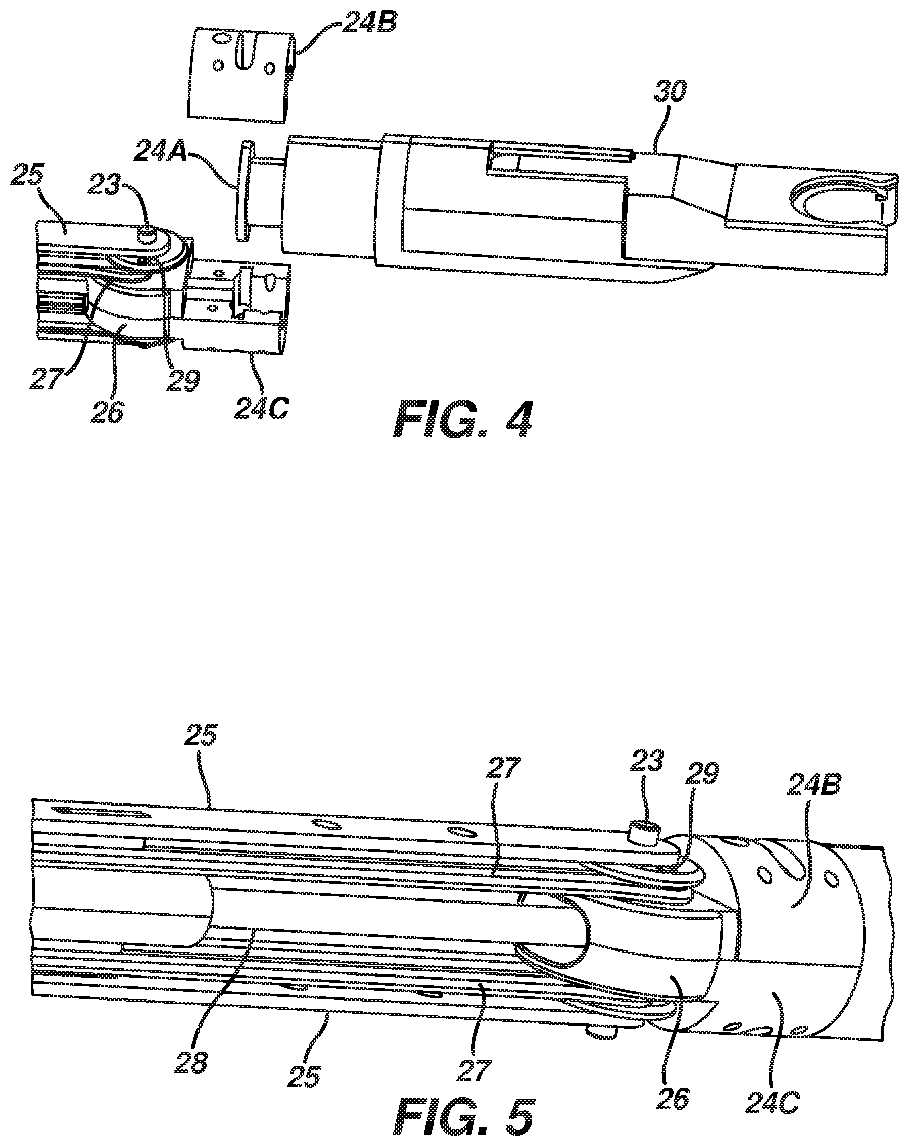
FIG. 4 depicts an exploded view of a shaft bearing;
FIG. 5 depicts a partial cut-away view showing the linkages in a shaft;
FIG. 6 depicts a perspective view of a cartridge receiver;
FIG. 7 depicts a perspective view of a rotary drive;
FIG. 8 depicts a perspective view of a cartridge disassembled from a receiver;
FIG. 9 depicts a perspective view of a cartridge disassembled from a receiver;
FIG. 10A depicts a perspective view of a transmission for driving a needle at one end of its stroke;
FIG. 10B depicts a perspective view of a transmission for driving a needle at mid-stroke;
FIG. 10C depicts a perspective view of a transmission for driving a needle at the other end of its stroke;
FIG. 11 depicts a perspective view of a needle driver in a carrier track;
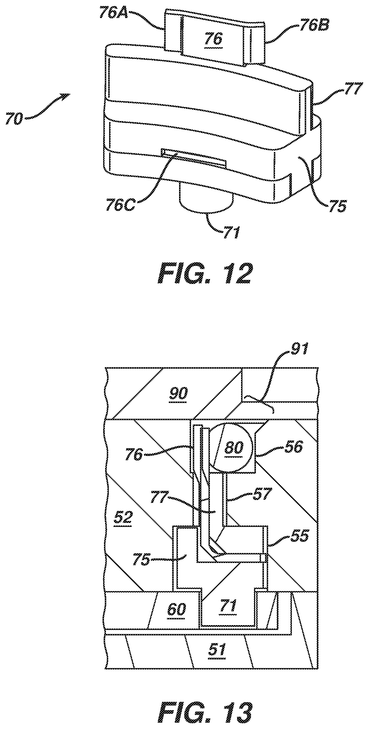
FIG. 12 depicts a perspective view of a needle driver;
FIG. 13 depicts a cross-sectional view of the needle driver in a carrier track and a needle in a needle track;
FIG. 14A depicts a plan view of arced needle;
FIG. 14B depicts a perspective view of arced needle;
FIG. 15A depicts a plan view of arced needle;
FIG. 15B depicts a perspective view of arced needle;
FIG. 16A depicts a plan view of a needle applier with a needle in its retracted position and the needle driver in its returned position;
FIG. 16B depicts a plan view of a needle applier with a needle in its extended position and the needle driver in its driven position;
FIG. 16C depicts a plan view of a needle applier with a needle in its extended position and the needle driver in its returned position;
FIG. 16D depicts a plan view of a needle applier with a needle in its retracted position and the needle driver in its driven position;
FIG. 17 depicts a perspective view of a cartridge receiver;
FIG. 18 depicts a perspective view of a rotary drive;
FIG. 19 depicts a perspective view of a latch;
FIG. 20 depicts a perspective view of a cartridge disassembled from a receiver;
FIG. 21 depicts a perspective view of a cartridge disassembled from a receiver;
FIG. 22A depicts a perspective view of a transmission for driving a needle at one end of its stroke;
FIG. 22B depicts a perspective view of a transmission for driving a needle at mid-stroke;
FIG. 22C depicts a perspective view of a transmission for driving a needle at the other end of its stroke;
FIG. 23A depicts a perspective view of a needle driver;
FIG. 23B depicts a perspective view of a needle driver;
FIG. 24 depicts a cross-sectional view of a needle driver in a carrier track and a needle in a needle track;
FIG. 25A depicts a plan view of arced needle;
FIG. 25B depicts a perspective view of arced needle;
FIG. 26A depicts a plan view of arced needle;
FIG. 26B depicts a perspective view of arced needle;
FIG. 27A depicts a plan view of a needle applier with a needle in its retracted position and the needle driver in its returned position;
FIG. 27B depicts a plan view of a needle applier with a needle in its extended position and the needle driver in its driven position;
FIG. 27C depicts a plan view of a needle applier with a needle in its extended position and the needle driver in its returned position;
FIG. 27D depicts a plan view of a needle applier with a needle in its retracted position and the needle driver in its driven position;
FIG. 28 depicts a plan view of a needle applier with a needle in its retracted position and the needle driver in its driven position;
FIG. 29A depicts a plan view of a needle applier with a needle in its retracted position and the needle driver in its returned position;
FIG. 29B depicts a plan view of a needle applier with a needle in its extended position and the needle driver in its driven position;
FIG. 29C depicts a perspective view of a pawl mechanism;
FIG. 29D depicts a plan view of a needle applier with a needle in its extended position and the needle driver in its returned position;
FIG. 30A depicts a plan view of a needle applier with a needle in its extended position and the needle driver in its driven position;
FIG. 30B depicts a perspective view of a pawl mechanism;
FIG. 31A depicts a plan view of a needle applier with a needle in its retracted position and the needle driver in its returned position;
FIG. 31B depicts a perspective view of a pawl mechanism;
FIG. 31C depicts a cross-sectional view of a pawl mechanism;
FIG. 32 depicts a perspective view of a cartridge disassembled from a receiver;
FIG. 33 depicts a perspective view of a cartridge disassembled from a receiver.
FIG. 34 depicts an exploded view of a cartridge packaging;
FIG. 35 depicts a perspective view of a cartridge being attached to a suturing device shaft; and
FIG. 36 depicts a perspective view of a cartridge packaging.
SUMMARY
In one embodiment, a surgical suturing device has an elongate shaft having a proximal end, a distal end, and a longitudinal axis between the proximal and distal ends. An actuator is connected to the proximal end of the elongate shaft. A circular needle applier is connected to the distal end of the elongate shaft. The elongate shaft articulates proximal of the circular needle applier and the circular needle applier rotates about the longitudinal axis.
The actuator may comprise a manual handle. The handle may comprise a first input to selectively actuate the circular needle applier. The surgical device may further comprise a second input to selectively articulate the shaft. The surgical device may further comprise a third input to selectively rotate the circular needle applier about the longitudinal axis. The elongate shaft may articulate about a joint. The circular needle applier may rotate about a bearing.
In another embodiment, a surgical suturing device has an elongate shaft has a proximal end, a distal end, and a longitudinal axis between the proximal and distal ends. An actuator is connected to the proximal end of the elongate shaft. A circular needle applier is on the distal end of the elongate shaft. The circular needle applier has an arced needle and a needle driver operatively connected to the actuator to rotate the arced needle in a circular path. A joint is positioned between the proximal and distal ends of the elongate shaft. The joint is operatively connected to the actuator to selectively articulate the shaft. A bearing is on the shaft positioned distally of the joint. The bearing is operatively connected to the actuator to selectively rotate the circular needle applier about the longitudinal axis.
In another embodiment, a surgical suturing device comprises an elongate shaft having a proximal end, a distal end, and a longitudinal axis between the proximal and distal ends. An actuator is connected to the proximal end of the elongate shaft. A circular needle applier is connected to the distal end of the elongate shaft. A means articulates the elongate shaft, and a means rotates the circular needle applier about the longitudinal axis. The surgical suturing device may further comprise a means to actuate the circular needle applier.
In another embodiment, a surgical suturing system comprises a reusable shaft and actuator. A disposable cartridge comprises a surgical needle, a length of suture connected to the surgical needle, and a needle driver operative to engage and move the needle relative the cartridge. The disposable cartridge may further comprise a transmission operatively connected to the needle driver. The reusable shaft and actuator may be autoclavable. The reusable shaft and actuator is reusable for at least 50 operations. The reusable shaft and actuator is reusable for at least 150 operations. The reusable shaft and actuator is reusable for at least 200 operations.
In another embodiment, a surgical suturing system comprises a reusable shaft having a proximal end and a distal end, the distal end has a receiver and a rotary drive. A reusable actuator is connected to the proximal end of the shaft. A disposable cartridge is adapted to be attached to and detached from the receiver. The cartridge comprises an arced track, an arced needle positioned in the track having a leading end and a trailing end, a length of suture connected to the trailing end, a reciprocating needle driver operative to engage and move the needle in the arced circular track, and a transmission operatively connected to the needle driver having a rotary input adapted to couple to the rotary drive. The reusable shaft and actuator may be autoclavable.
In another embodiment, a disposable surgical needle cartridge is adapted to be attached to and detached from a surgical suturing device. The disposable cartridge comprises an arced needle track, an arced needle positioned in the needle track having a leading end and a trailing end, a length of suture connected to the needle, a reciprocating needle driver operative to engage and move the needle in the needle track, a transmission operatively connected to the needle driver, and a torsional interface adapted to couple the transmission to a rotary drive in the surgical suturing device. The reciprocating needle driver and transmission are completely encased in the cartridge. The surgical suturing device may be reusable. The surgical suturing device may comprise an elongate shaft with a proximal end, a distal end, and a receiver adapted to interface with the cartridge. The disposable surgical needle cartridge may further comprise a surgical suturing device.
In another embodiment, a surgical suturing system comprises a shaft having a proximal end, a distal end, a longitudinal axis between the proximal and distal ends, and receiver on the distal end with a rotary drive. A cartridge is selectively attachable to and detachable from the receiver. The cartridge has a surgical needle, a length of suture connected to the needle, a needle driver operative to engage and move the needle relative the cartridge, a transmission operatively connected to the needle driver, and a torsional interface rotationally coupling the rotary drive to the transmission.
The rotary drive may deliver a torque to the transmission through the torsional interface about an axis transverse to the longitudinal axis of the shaft. The rotary drive may deliver a torque through the torsional interface about an axis perpendicular to the longitudinal axis of the shaft. The rotary drive may comprise a rack and pinion. The receiver may comprise a distally extending arm axially off-set from the longitudinal axis of the shaft. The arm may comprise a medially facing deck. The rotary drive may be positioned at least partially in the arm.
The surgical suturing system may further comprise a second distally extending arm axially off-set from the longitudinal axis of the shaft, the arms defining a space dimensioned and adapted to receive the cartridge. The surgical suturing system may further comprise a latch operable to lock and unlock the cartridge to the receiver. The cartridge may be attached to and detached from the receiver by longitudinally sliding the cartridge relative to the receiver.
In another embodiment, a surgical suturing system comprises a shaft having a proximal end, a distal end, and a longitudinal axis between the proximal and distal ends. A receiver is on the distal end of the shaft. The receiver has a pair of distally extending arms defining a space. A cartridge is selectively attachable to and detachable from the receiver by longitudinally sliding the cartridge in the space. The cartridge has a surgical needle, a length of suture connected to the needle, a needle driver operative to engage and move the needle relative the cartridge. A latch selectively locks and unlocks the cartridge in the receiver.
The surgical suturing system may further comprise a rotary drive positioned at least partially in one of the arms. The surgical suturing system may further comprise a transmission in the cartridge operatively connected to the needle driver, and a torsional interface rotationally coupling the rotary drive to the transmission.
In another embodiment, a surgical suturing system comprises a shaft having a proximal end, a distal end, a longitudinal axis between the proximal and distal ends, and receiver on the distal end with a rotary drive. A cartridge is selectively attachable to and detachable from the receiver. The cartridge has a surgical needle, a length of suture connected to the needle, a needle driver operative to engage and move the needle relative the cartridge, and a transmission operatively connected to the needle driver. A means rotationally couples the rotary drive to the transmission. The surgical suturing system may further comprise a means for attaching and detaching the cartridge to the receiver. The surgical suturing system may further comprise a means for locking and unlocking the cartridge in the receiver.
In another embodiment, a surgical suturing device comprises an arced needle track. An arced needle is positioned in the needle track, the needle having a leading end, a trailing end, a medial face, and a lateral face. A length of suture is connected to the needle. An arced carrier track is spaced from the needle track. A reciprocating needle driver has a carrier positioned in the carrier track and a driver positioned in the needle track and is operative to engage and move the needle in the needle track. A transmission is operative to reciprocate the carrier in the carrier track.
The surgical suturing device may further comprise a wall separating the carrier track from the needle track. The surgical suturing device may further comprise a slotted opening through the wall, the slot communicating between the carrier track and the needle track. The needle driver may extend through the slotted opening and into the needle track. The slotted opening may be adjacent the medial edge of the arced needle track. The slotted opening may be adjacent the lateral edge of the arced needle track. The arced needle track and arced carrier track may be co-axial. The needle track and carrier track may be off-set along the shared axis from one another. The needle track and carrier track may be co-radial. The needle may further comprise steps dimensioned and adapted to be engaged by the driver. The steps may be on the medial face of the needle. The steps may be on the lateral face of the needle.
In another embodiment, a surgical suturing device comprises an arced needle track. An arced needle is positioned in the needle track. The needle has a leading end, a trailing end, a medial face, and a lateral face. A length of suture is connected to the needle. An arced carrier track is off-set along a shared axis with the arced needle track. A wall separates the arced needle track from the arced carrier track. The wall has a slotted opening communicating between the arced carrier track and the arced needle track. A reciprocating needle driver has a carrier positioned in the arced carrier track and a driver positioned in the arced needle track operative to engage and move the needle in the needle track. A transmission is operative to reciprocate the carrier in the carrier track.
In another embodiment, a surgical suturing device comprises an arced needle track, an arced needle positioned in the needle track, and a length of suture connected to needle. A reciprocating needle driver is operative to engage and move the needle in the needle track. A rotary input rotates about an axis. A link has a proximal end connected to the rotary input and a distal end connected to the needle driver. Rotation of the rotary input in a first angular direction translates the needle driver in a second angular direction opposite of the first angular direction.
The link may further comprise a longitudinal slot interposed between the proximal and distal ends, the longitudinal slot receiving a pin about which the link both longitudinally translated and pivots. The distal end may be pivotally connected to the needle driver. The connection between the needle driver and link distal end may translate in an arced path having a first radius. The proximal end of the link may connect to the rotary input at a second radius from the torsion drive axis, and the first radius may be greater than the second radius. The rotary input, link, and needle driver may have no indeterminate point. The rotary input may comprise a radial slot receiving a pin connected to the proximal end of the link. The surgical suturing device of may further comprise an elongate shaft having a proximal end and a distal end, an actuator connected to the shaft proximal end, a rotary drive operably connected to the actuator, and a torsional interface rotationally coupling the rotary driver to the rotary input. The rotary drive may comprise a rack and pinion. The rotary input may have a reciprocating rotational motion. The needle driver may reciprocate at least 180 degrees in an arced track. The needle driver may rotate the needle in a circular path at least partially defined by the needle track. The rotary input and needle may rotate in parallel planes.
In another embodiment, a surgical suturing device comprises a needle having a leading end, a trailing end, and an arced body between the leading and trailing ends. A length of suture is connected to the needle. A needle driver is adapted to engage and rotate the needle in a circular path in a first rotational direction. A pawl is adapted to engage the trailing end of the needle to prevent the needle from rotating in a second rotational direction opposite of the first rotational direction.
The needle may be rotated in a plane, and the pawl may resiliently deflect at an angle transverse to the plane. The pawl may resiliently deflect substantially perpendicular to the plane. The needle may be rotated in a plane, and the pawl may resiliently deflect substantially in the plane. The pawl may be positioned laterally from the needle. The pawl may be positioned medially from the needle. The pawl may have a first end about which the pawl pivots, and a second end having an edge that engages the trailing end of the needle. The surgical suturing device may further comprise a second pawl adapted to engage the trailing end of the needle to prevent the needle from rotating in a second rotational direction opposite of the first rotational direction. The pawls may be antipodal to one another along the circular path. The trailing end may comprise a barrel receiving the suture, the barrel having a trailing face circumscribing the suture and the pawl may engage the trailing face to prevent the needle from rotating in a second rotational direction opposite of the first rotational direction. The pawl may translates along a path perpendicular to the needle path, and the pawl may further comprise a spring biasing the pawl in the needle path. The pawl may further comprise a ramp adapted to be engaged by the needle to deflect the pawl out of the needle path and allow the needle to pass the pawl. The pawl may translate along a path transverse a plane defined by the circular needle path.
In another embodiment, a surgical suturing device comprises a needle having a leading end, a trailing end, an arced body between the leading and trailing ends, and two steps located at antipodal positions on the body. A length of suture is connected to the needle. A needle driver reciprocates at least 180 degrees between a driven position and a returned position. The needle driver is adapted to engage the needle steps to rotate the needle in a circular path in first rotational direction. A pawl is positioned adjacent the driven position of the needle driver. The pawl is adapted to engage the needle steps to prevent the needle from rotating in a second rotational direction opposite of the first rotational direction.
The surgical device may further comprise a spring biasing the pawl in the needle path. The pawl may further comprise a ramp adapted to be engaged by the needle and the needle driver to deflect the pawl out of the needle path and allow the needle and needle driver to pass the pawl. The pawl may deflect in a plane defined by the circular needle path. The pawl may have a first end about which the pawl pivots, a second end having an edge that engages the needle steps, and a spring biasing the second end into the needle path. In the driven position the needle driver may be interposed between the pawl and the needle. The surgical device may further comprise a second a pawl positioned adjacent the returned position of the needle driver, the second pawl adapted to engage the needle steps to prevent the needle from rotating in a second rotational direction opposite of the first rotational direction.
In another embodiment, a surgical suturing device comprises a needle having a leading end, a trailing end, an arced body between the leading and trailing ends, and two steps located at antipodal positions on the body. A length of suture is connected to the needle. A needle driver reciprocates at least 180 degrees between a driven position and a returned position. The needle driver is adapted to engage the needle steps to rotate the needle in a circular path in first rotational direction. A pawl is positioned adjacent the returned position of the needle driver. The pawl is adapted to engage the needle steps to prevent the needle from rotating in a second rotational direction opposite of the first rotational direction.
The surgical device may further comprise a spring biasing the pawl in the needle path. The pawl may further comprise a proximal ramp adapted to be engaged by the needle and the needle driver to deflect the pawl out of the needle path and allow the needle and needle driver to pass the pawl. The pawl may further comprise a distal ramp adapted to be engaged by the needle driver to deflect the pawl out of the needle path and allow the needle driver to pass the pawl. The distal ramp may be positioned below the needle path. The pawl may deflect in a plane defined by the circular needle path.
In another embodiment, a surgical suturing device comprises a needle having a leading end, a trailing end, an arced body between the leading and trailing ends, and two steps located at antipodal positions on the body. A length of suture connected to the needle. A needle driver reciprocates at least 180 degrees between a driven position and a returned position. The needle driver is adapted to engage the needle steps to rotate the needle in a circular path in first rotational direction. A means engages the needle steps to prevent the needle from rotating in a second rotational direction opposite of the first rotational direction. The means may comprise a pawl. The means may comprise a leaf spring.
In another embodiment, a surgical needle for use in a circular needle applier comprises a leading end, a trailing end, and an arced body between the leading and trailing ends. The body has a medial face and a lateral face. A plurality of steps on the body are adapted to be engaged by a circular needle applier. The steps are formed by plastically deforming the body without removing material. A length of suture is connected to the trailing end.
The steps may be on the medial face. The steps may be on the lateral face. The steps may be formed by a pressing operation. The steps may be formed by a rolling operation. The plurality of steps may comprise two antipodal steps. The body may have an angular span of at least 180 degrees. The arced body may comprise a substantially constant nominal radius about an origin.
In another embodiment, a surgical needle for use in a circular needle applier comprises a leading end has a taper, a trailing end has a barrel, and an arced body extending between the taper and barrel. The body has a medial face, a lateral face, and plurality of steps adapted to be engaged by a circular needle applier. The body has a substantially constant cross sectional area between the taper and barrel. A length of suture is connected in the barrel.
The steps may be on the medial face. The plurality of steps may consist of two antipodal steps on the medial face. The steps may be on the lateral face. The plurality of steps may consist of two antipodal steps on the lateral face. The steps may be formed without removing material from the body. The steps may be formed by a pressing operation. The steps may be formed by a rolling operation. The plurality of steps may comprise two antipodal steps. The body may have an angular span of at least 180 degrees.
In another embodiment, a surgical needle for use in a circular needle applier comprises a distal leading end, a proximal trailing end, and an arced body between the leading and trailing ends. The body has a medial face and a lateral face. A first step on the body is adapted to be engaged by a circular needle applier. The first step is positioned distally from the leading end. A longitudinal flat extends proximally from the first step. The flat defines a generally D-shaped cross sectional shape in the body. A second step on the body is adapted to be engaged by a circular needle applier. The second step is positioned about 180 degrees from the first step. A length of suture is connected to the trailing end.
The needle may have an angular span from the leading end to the trailing end between about 210 degrees and about 270 degrees. The first and second steps may be located on the medial face. The first and second steps may be located on the lateral face. The arced body may comprise a substantially constant nominal radius about an origin. The nominal radius may be between about 0.170 inches to about 0.210 inches. The flat may extend proximally from the first step between about 20 degrees and about 40 degrees. The flat may extend proximally from the first step between about 100 degrees and about 150 degrees. The body may further comprise a ramped portion on the proximal end of the flat such that the cross sectional shape in the body transitions from a generally D-shape to a generally circular shape. The body may further comprise a second longitudinal flat extending proximally from the second step, the second flat defining a generally D-shaped cross sectional shape in the body. The second flat may extend proximally from the second step between about 8 degrees and about 30 degrees. The body may further comprise a ramped portion on the proximal end of the second flat such that the sectional shape in the body transitions from a generally D-shape to a generally circular shape. The leading end may comprise a taper and the trailing end may have a barrel, and the body may have a substantially constant cross sectional area between the taper and barrel.
In another embodiment, packaging for a surgical needle comprises a cartridge having a surgical needle and a needle driver operative to engage and move the needle relative the cartridge. The packaging has a bobbin, and a length of suture connected to the needle and wound around the bobbin. The packaging may further comprise an outer shell enclosing the cartridge, bobbin, and suture. The outer shell may comprise a sheet of material folded over the cartridge and bobbin. The packaging may further comprise a platform resiliently holding the cartridge. The bobbin may be a rotating spool. The cartridge may comprise a pair of arms defining a generally U-shaped distal end, and the packaging may have a block interposed between the arms. The packaging may further comprise a housing and a top sheet enclosing the enclosing the cartridge, bobbin, and suture.
In another embodiment, packaging for a surgical needle a housing and a cartridge releasably held in the housing. The cartridge has a surgical needle and a needle driver operative to engage and move the needle relative the cartridge. A bobbin is in the housing. A length of suture is connected to the needle and wound around the bobbin. The cartridge, bobbin, and suture may be enclosed within the housing. The cartridge may comprise a pair of arms defining a generally U-shaped distal end, and the packaging may further comprise a block attached to the housing and extending between the arms. The housing may define a gap and the cartridge may be positioned at least partially in the gap.
In another embodiment, packaging for a surgical needle comprises a housing having a gap. A cartridge is releasably held in the housing and extends into the gap. The cartridge has a surgical needle, a needle driver operative to engage and move the needle relative the cartridge, and a pair of arms defining a generally U-shaped distal end. A block is attached to the housing and extends between the arms. A rotary spool is in the housing. A length of suture is connected to the needle and wound around the spool. The cartridge, bobbin, and suture are enclosed within the housing.
DETAILED DESCRIPTION
FIG. 1 illustrates an embodiment of a surgical suturing device. An elongate shaft (20) has a proximal end (21), a distal end (22), and a longitudinal axis extending there between. An actuator (10) is connected to the proximal end (21) of the shaft (20). In this embodiment the actuator (10) is a manual pistol grip handle; however, a variety of other manual actuators could also be used, including a scissor grip handle, a syringe grip handle, endoscopic rotary knobs, and the like. The actuator (10) could also take the form of a robotic interface, such as an DAVINCI puck, a housing comprising gears or pulleys, servomechanisms, and the like.
A circular needle applier (30) is connected to the distal end (22) of the shaft (20). The circular needle applier (30) rotates an arced needle in a circular path enabling a surgeon to selectively apply sutures. The circular needle applier (30) may be integral with the shaft (20) and actuator (10) as a unitary disposable instrument intended for a single surgical procedure. The circular needle applier (30) may also be integral with the shaft (20) and actuator (10) as a reusable instrument. Optionally, the circular needle applier (30) may be embodied in a disposable cartridge, and the shaft (20) and actuator (10) may also be disposable. In another variation, the circular needle applier (30) may be embodied in a disposable cartridge, and the shaft (20) and actuator (10) may be reusable. Embodiments with reusable components are intended to be cleaned, sterilized, and reused for a multiple surgical procedures. The preferable life cycle of a reusable instrument is at least 50 operations, more preferably at least 150 operations, and most preferably at least 200 operations. Reusable components may be built using materials that can withstand autoclave sterilization temperatures of at least 135 degrees Celsius, although low temperature materials can also used with low temperature sterilization techniques known in the art.
FIG. 2 illustrates one embodiment of a manual actuator (10). A first input (12), shown here as a trigger that pivots between an opened and closed position, may be used to selectively actuate the circular needle applier (30). The trigger may be spring biased to return the trigger to its open position. A second input (14), shown here as a rotary knob, may be used to selectively articulate the shaft (20). A third input (16), shown here as a rotary knob, may be used to selectively rotate the circular needle applier (30) about the shaft (20). A fourth input (18), shown here as a switch, may be used to selectively attach and detach a circular needle applier (30) to the shaft (20). Naturally, the number, type, configuration, and operation of the inputs (12, 14, 16, and 18) may vary.
FIGS. 3A-B illustrate the shaft (20) articulating in response actuation of the second input (14). In this embodiment, the shaft (20) has an articulation joint (23) to facilitate articulation. The shaft (20) includes a bearing (24) positioned distal to the joint (23). FIGS. 3B-C illustrate the circular needle applier (30) rotating at the bearing (24) in response to actuation of the third input (16), even when the shaft (20) is articulated.
FIGS. 4-5 illustrate one example of a suitable articulation joint (23) and rotation bearing (24). The bearing (24) includes a circumferential flange (24A) fixed to the circular needle applier (30). The flange (24A) is captured between the bearing supports (24B, 24C) such that the flange (24A) can rotate but prevent axial motion. A flexible co-axial torsion tube (28) passes through the joint (23). The torsion tube (28) has an outer sheath and an inner cable. The outer sheath of the torsion tube (28) is fixed to the flange (24A) and operatively connected to the third input (16). Actuation of the third input (16) will rotate the sheath and in turn rotate circular needle applier (30). The inner cable of the co-axial torsion tube (28) passes through the circumferential flange (24A) and is operatively connected to the first input (12) to provide axial push and pull loads to actuate the circular needle applier (30). Lateral struts (25) support the joint (23) in the shaft (20). A pin (29) connects the rods (27) to the knuckle (26) at a position off-set from the axis of the joint (23). The rods (27) are operatively connected to the second input (14) to push and pull the rods (27) relative the struts (25), which will in turn articulate the shaft (20) about the joint (23).
FIG. 6 illustrates one example of a receiver (40) located on the distal end (22) of the shaft (20). The receiver (40) is dimensioned and adapted to receive and hold a disposable cartridge containing a circular needle applier (30). The cartridge may contain a surgical needle, a length of suture connected to the surgical needle, a needle driver operative to engage and move the needle relative the cartridge, and a transmission operatively connected to the needle driver. An axially off-set arm (41) extends distally from the shaft (20). The arm (41) has a medially facing deck (49) with a pair of longitudinal slots (44) located below and on either side of the deck (49). A spring loaded latch (43) is adapted to selectively lock and unlock the cartridge to the receiver (40). Optionally, latch (43) may be operatively coupled to the fourth input (18).
FIG. 7 illustrates a rotary drive having a rack (45) and pinion (47) is positioned partially in the arm (41) and below the deck (49). The inner cable of the co-axial torsion tube (28) is connected to the proximal end (46) of the rack (45) such that closing the trigger of the first input (12) will pull the rack (45) proximally, and opening the trigger of the first input (12), which may be by virtue of a spring return, will push the rack (45) distally. Thus, actuating the first input (12) will rotationally reciprocate the pinion (47). The key (48) translates the reciprocating rotation to the transmission in the cartridge.
FIGS. 8-9 illustrate one example of a disposable cartridge (50) adapted to be attached to the receiver (40). The cartridge (50) may be slid proximally onto the receiver (40) so the two decks (49, 59) are parallel and facing one another until the latch (43) engages the recess (53). The cartridge (50) in encased by a lower housing (51), an upper housing (52), and a needle cover (90). The lower housing (51) has a pair of longitudinal slots (54) dimensioned to interface and mate with the slots (44). The slot (58) is dimensioned to receive the key (48) while the cartridge (50) is being slid onto the receiver (40). When the cartridge (50) is fully seated into the receiver (40), the pinion (47) is axially aligned with rotary input (67), which forms part of the transmission in the cartridge (50), and the key (48) is positioned in the slot (68) thereby providing a torsional interface that rotationally couples the pinion (47) and rotary input (67).
Thus, the rotary drive in the shaft (20) delivers an operational torque to the transmission in the cartridge (50) about an axis perpendicular to the longitudinal axis of the shaft (20). The operational torque could also be delivered along an axis parallel or in line with the longitudinal axis of the shaft (20), or at another transverse angle relative the longitudinal axis of the shaft (20). Further, other torsional interfaces known in the art other than the key (48) and slot (68) embodiment may be used, such as a cross, star, square, spline, and the like.
FIGS. 10A-C illustrate one example of a transmission in the cartridge (50) for driving a needle in a circular path. A needle driver (70) reciprocates in the arced carrier track (55) and is operative to engage and rotate an arced needle. A link (60) connects the rotary input (67) to the needle driver (70). The pin (71) pivotally connects the distal end of the link (60) to the needle driver (70). The rotary input (67) has a slot (68) that mates with the key (48) so as to receive the reciprocating rotation from the rotary drive. The rotary input (67) has a radially extending arm (65) with a radial slot (66). The pin (64) is positioned in the slot (66) connecting the proximal end of the link (60) to the rotary input (67). The slot (66) rotationally constrains the pin (64) to the arm (65) while accommodating some relative radial movement. The link (60) has a longitudinal slot (61) receiving the fixed pin (62) about which the link (60) both longitudinally translates and pivots. The pins (71, 62) are co-planar, but pin (66) lies in an off-set plane. The link (60) includes a bent section (63) to accommodate the off-set. Other than the torsional interface, which in this embodiment comprises the face of the rotary input (67) with the slot (68), the entire transmission is completely encased within cartridge (50).
FIG. 10A illustrates the needle driver (70) positioned at one end of its stroke in the carrier track (55). As shown in FIG. 10B, counterclockwise rotation of the rotary input (67) will translate the needle driver (70) clockwise along the carrier track (55). The radius of rotation of the pin (71) is greater than the radius of rotation of the pin (64). As shown in FIG. 10C, continued counterclockwise rotation of the rotary input (67) will continue to translate the needle driver (70) clockwise until it reaches the other end of its stroke in the carrier track (55). The rotary input (67), link (60), and needle driver (70) have no indeterminate point, so rotation of the rotary input (67) will cause the needle driver (70) to translate in the opposite rotational direction throughout the stroke without binding.
The sequence can be reversed by rotating the rotary input (67) clockwise, which will translate the needle driver (70) counterclockwise in the carrier track (55). Thus, actuation of the first input (12) will cause the needle driver (70) to reciprocate back and forth along the carrier track (55).
FIGS. 11-13 illustrate one example of a needle driver (70) and its operation. The upper housing (52) has an arced needle track (56) and an arced carrier track (55). In this embodiment, the needle track (56) and carrier track (55) each have a nominal radius of curvature originating from a common axis. Therefore, the needle track (56) and carrier track (55) are co-axial. Also in this embodiment, the tracks (55, 56) at least partially overlap one another in the radial dimension, so they are also co-radial. The tracks (55, 56) are off-set along the shared axis from one another with a wall separating the tracks (55, 56). A slot (57) opens through the wall and provides communication between the carrier track (55) and the needle track (56). In this embodiment the slot (57) opens adjacent the lateral edge of the needle track (56).
The needle driver (70) has a carrier (75) dimensioned to slideably fit in the carrier track (55). In this embodiment, the carrier (75) has a curved body matching the arc of the carrier track (55). The pin (71) extends from the carrier (75) to engage the link (60). The needle driver (70) extends through the slot (57) and into the needle track (56). The carrier (75) has a flange (77) dimensioned to fit in the slot (57). A driver (76) is attached to the carrier (75) and is positioned in the needle track and operative to engage and move the needle (80) in the needle track (56). The driver (76) is an L-shaped metal blade with one leg (76C) sandwiched between two pieces that form the carrier (75). The driver (76) may deflect as a cantilevered leaf spring laterally from the flange (77), and may also resiliently bias to engage the lateral face of the needle (80). In this embodiment the driver (76) has a drive face (76A) and a return face (76B). The drive face (76A) has an edge that is operative to engage steps on the needle (80) during the drive stroke. When so engaged, the needle (80) will slide in the needle track (56) in unison with the driver (70). The return face (76B) is ramped to facilitate the driver (76) sliding over the needle (80) on the return stroke.
The lower housing (51) constrains the link (60) to engage the pin (71) and also constrains the carrier (75) in the carrier track (55). The needle cover (90) constrains the needle (80) in the needle track (56). The needle cover (90) also defines a window (91) along the length of the needle track (56). The window (91) is dimensioned to receive the suture. As the needle (80) is rotated in the needle track (56), the suture may extend out through the window (91). However, the window (91) is dimensioned smaller than the needle (80) so as to constrain the needle (80) in the needle track (56).
FIGS. 14A-B illustrates one embodiment of a needle (80) having a distal leading end (81) with a sharp tapered tip (83). A variety of geometries could be employed at the leading end (81), including conical, bladed, blunt, cutting tips, taper-cut tips, and the like. The proximal trailing end (82) has a tubular barrel (84) that fixedly receives a length of suture (89). A trailing face (88) circumscribes the suture (89). A variety of different types of suture (89) may be employed, including braided, monofilament, and barbed suture using a variety of materials, including polyglactin (e.g., VICRYL), poliglecprone (e.g., MONOCRYL), polydioxanone (e.g., PDS), surgical gut, polyester (e.g., ETHIBOND), silk (e.g. PERMA-HAND), polypropylene (e.g., PROLENE), other absorbable or non-absorbable materials, and the like.
The angular span between the leading end (81) and trailing end (82) may be between about 210 degrees and about 270 degrees. An arced body (85) extends between the tapered tip (83) and the barrel (84). The body (85) may arc at a substantially constant radius of curvature. The nominal radius of curvature may be between about 0.170 inches to about 0.210 inches, preferably between about 0.180 inches to about 0.205 inches, and more preferably between about 0.190 inches to about 0.200 inches; however, other dimensions are also possible.
A distal step (86A) is positioned on the lateral face of the body (85). The distal step (86A) may be located between about 20 degrees and about 30 degrees from the leading end (81). A proximal step (87A) is positioned on the lateral face of the body (85). The proximal step (87A) is about 180 degrees from the distal step (86A). Therefore, the steps (86A, 87A) are located at antipodal locations on the needle (80). The steps (86A, 87A) are adapted to be engaged by the driver (76) of the needle driver (70). The height of the steps (86A, 87A) are preferably between about 0.003 inches and about 0.010 inches, but other dimensions are also possible. Flats (86B, 87B) extend distally from the steps (86A, 87A) and define a generally D-shaped cross sectional shape in the body (85). The distal flat (86B) has an angular span between about 20 degrees and about 40 degrees from the distal step (86A). The proximal flat (87B) has an angular span between about 8 degrees and about 30 degrees from the distal step (87A). The flats (86B, 87B) may facilitate reducing the dimensional interference between the needle (80) and driver (76) during the return stroke of the needle driver (70). Ramps (86C, 87C) are located adjacent the proximal ends the flats (86B, 87B) such that the cross-sectional shape of the body (85) transitions from a generally D-shape to a generally circular shape. The ramps (86C, 87C) reduce the likelihood of the driver (76) snagging on the needle (80) during the return stroke of the needle driver (70).
The step, flat, and ramp features (86A, 87A, 86B, 87B, 86C, 87C) may be made by plastically deforming the body (85). For instance, a die can be used in a pressing or rolling operation on a straight wire stock to form the features on the body (85). Then the straight stock can be bent to its arced shape. While the cross-sectional shape of the body (85) will change along its length, the cross-sectional area between the taper (83) and the barrel (84) will remain substantially constant. This is advantageous over notched needle designs where material is being removed to create notches, such as in a cutting or grinding operation, resulting in a weaker needle. Furthermore, plastically forming features in the body (85) is more reliable and reproducible, and capable of faster production.
FIGS. 15A-B illustrates another embodiment of needle (80) substantially the same as in FIGS. 14A-B; however, the distal flat (86B) has an angular span between about 100 degrees and about 150 degrees from the distal step (86A).
FIGS. 16A-D illustrate one embodiment of a circular needle applier (30) rotating an arced needle (80) in a circular path. The suture has been hidden in the figures to better illustrate device operation. A pair of arms (94, 95) define a generally U-shaped distal end on the circular needle applier (30). The needle track (56) has an exit port (92) in arm (94) and an entrance port (93) in arm (95). The leaf springs (96, 97) allow the needle (80) to rotate counterclockwise, but prevent the needle (80) from rotating clockwise. Leaf spring (97) extends into the needle track (56) and resiliently deflects laterally when engaging the lateral face of the needle (80), thus allowing counterclockwise motion. Leaf spring (96) extends into the needle track (56) and resiliently deflects medially when engaging the medial face of the needle (80), thus allowing counterclockwise motion. But when the needle (180) passes one of the leaf springs (96, 97), it will deflect into the path to interfere and engage the trailing face (88), thus preventing the needle (80) from rotating clockwise.
FIG. 16A shows the device in its initial position. The needle (80) is in its retracted position and completely contained in the needle track (56). The needle driver (70) has a reciprocating stroke between a returned position and a driven position. In this figure, the driver (76) is in its returned position in arm (95). The driver (76) is adjacent the proximal step (87A). Leaf spring (96) resiliently engages the needle (80), while leaf spring (97) is adjacent the trailing face (88) preventing the needle (80) from rotating clockwise.
When the first input (12) is depressed closing the trigger, the needle driver (70) will be actuated through its drive stroke where it is rotated at least about 180 degrees counterclockwise to the driven position as shown in FIG. 16B. During the drive stroke, the driver (76) engages the proximal step (87A) and will in unison rotate the needle (80) about 180 degrees to its extended position. The needle (80) will span across the arms (94, 95) between the exit port (92) and the entrance port (93). Tissue interposed between the arms (94, 95) will be pieced by the leading end (81) of the needle (80).
When the first input (12) is released and the spring return opens the trigger, the needle driver (70) reciprocates through its return stroke where it is rotated about 180 degrees clockwise back to the return position shown in FIG. 16C. During the return stroke the driver (76) slides over the needle (80) and the leaf spring (96) engages the trailing face (88) preventing the needle (80) from rotating clockwise. The driver (76) is adjacent the distal step (86A).
When the first input (12) is depressed again closing the trigger, the needle driver (70) will again be actuated through its drive stroke where it is rotated about 180 degrees counterclockwise to the driven position as shown in FIG. 16D. During the drive stroke, the driver (76) engages the distal step (86A) and will in unison rotate the needle (80) about 180 degrees back to its retracted position. The suture will follow the needle (80) and be threaded through the pieced tissue.
When the first input (12) is again released and the spring return opens the trigger, the needle driver (70) again reciprocates through its return stroke where it is rotated about 180 degrees clockwise back to its returned position as shown in FIG. 16A. During the return stroke the driver (76) slides over the needle (80) and the leaf spring (97) engages the trailing face (88) preventing the needle (80) from rotating clockwise. Thus, the needle (80) is driven in a complete circular path. The sequence may be repeated as needed by the surgeon to achieve the desired suturing task.
FIGS. 17-21 illustrate another embodiment of a receiver (140) located on the distal end (22) of the shaft (20). The receiver has an axially off-set lower arm (141) and an axially off-set upper arm (142), each having a longitudinal slot (144). A spring loaded latch (143) is adapted to selectively lock and unlock the cartridge (150) in the receiver (140). A rack (145) and pinion (147) rotary drive is positioned in the lower arm (141). The inner cable of the co-axial torsion tube (28) is connected to the proximal end (146) of the rack (145). The rack (145) is bent to accommodate the axial off-set of the lower arm (141). The key (148) mates with the slot (168) to translate the reciprocating rotation of the pinion (147) to the rotary input (168) in the cartridge (150).
The disposable cartridge (150) is adapted to be attached to the receiver (140). The cartridge (150) may be slid proximally between the arms (141, 142) of the receiver (140) until the latch (143) engages the step (152). The step (154) mates with the longitudinal slot (144) in the lower arm (141), and the step (152) mates with the longitudinal slot (144) in the upper arm (142). The slot (158) is dimensioned to receive the key (148) while the cartridge (150) is being slid onto the receiver (140). When the cartridge (50) is fully seated into the receiver (140), the pinion (147) is axially aligned with rotary input (167) and the key (148) is positioned in the slot (168) thereby rotationally coupling the rotary drive to the rotary input (167).
FIGS. 22A-C illustrate one example of a transmission in the cartridge (150) for driving a needle in a circular path. A needle driver (170) reciprocates in the arced carrier track (155). A straight link (160) connects the rotary input (167) to the needle driver (170). The pin (171) pivotally connects the distal end of the link (160) to the needle driver (170). The rotary input (167) a radial slot (166). The pin (164), hidden from view below the link (160), is positioned in the slot (166) to connect the proximal end of the link (160) to the rotary input (167). The slot (166) rotationally constrains the pin (164) while accommodating some relative radial movement. The link (160) has a longitudinal slot (161) receiving the fixed pin (162) about which the link (160) both longitudinally translates and pivots. The needle driver (170) and rotary input (167) are co-planar. A tooth (165) engages stops in the cartridge to limit the rotational stoke of the rotary input (167).
FIG. 22A illustrates the needle driver (170) positioned at one end of it stroke in the carrier track (155). As shown in FIG. 22B, clockwise rotation of the rotary input (167) will translate the needle driver (170) counterclockwise along the carrier track (155). As shown in FIG. 22C, continued clockwise rotation of the rotary input (167) will continue translate the needle driver (170) counterclockwise until it reaches the other end of its stroke in the carrier track (155). The rotary input (167), link (160), and needle driver (170) have no indeterminate point, so rotation of the rotary input (167) will cause the needle driver (170) to translate in the opposite rotational direction throughout the stroke without binding. The sequence can be reversed by rotating the rotary input (167) counterclockwise, which will translate the needle driver (170) clockwise in the carrier track (55).
FIG. 23A illustrates one embodiment of a needle driver (170). A carrier (175) is dimensioned to slideably fit in the carrier track (155). The carrier (175) may be a monolithic component with an arced shaped. The pin (171) extends from the carrier (175). The driver (176) extends from the carrier (175) through the slot (157) and into the needle track (156). The driver (176) is an L-shaped metal blade with one leg (176C) having a hole that fits over the pin (171) and is seated against the carrier (175). The driver (176) has a drive face (176A) and a return face (176B). In this embodiment, the drive face (176A) and return face (176B) are generally co-planar and symmetrical. FIG. 23B shows another embodiment where the drive face (176A) is bent toward the needle (180).
As shown in FIG. 24, the needle track (156) and carrier track (155) are co-axial and co-radial. The tracks (155, 156) are off-set along the shared axis from one another with a wall separating the tracks (155, 156). A slot (157) opens through the wall and provides communication between the carrier track (155) and the needle track (156). In this embodiment the slot (157) opens adjacent the medial edge of the needle track (156). The needle (180) slideably fits in the needle track (156) and the carrier (175) slideably fits in the carrier track (155). The driver (176) extends through the slot (157) and into the needle track (156). The driver (176) is arranged as a cantilever leaf spring resiliently engaging the medial face of the needle (180). As the needle (180) is rotated in the needle track (156), the suture may extend out through the window (191).
FIGS. 25A-B illustrates an embodiment of a needle (180) having a distal leading end (181) with a sharp tapered tip (183). The proximal trailing end (182) has a tubular barrel (184) that fixedly receives a length of suture (189). A trailing face (188) circumscribes the suture (189). An arced body (185) extends between the tapered tip (183) and barrel (184). A distal step (186A) is positioned on the medial face of the body (185). The distal step (186A) may be located between about 20 degrees and about 30 degrees from the leading end (181). A proximal step (187A) is positioned on the medial face of the body (185) about 180 degrees from the distal step (186A). The steps (186A, 187A) are adapted to be engaged by the driver (176) of the needle driver (170). Flats (186B, 187B) extend distally from the steps (186A, 187A) and define a generally D-shaped cross sectional shape in the body (185). The distal flat (186B) has an angular span between about 20 degrees and about 40 degrees from the distal step (186A). The proximal flat (187B) has an angular span between about 8 degrees and about 20 degrees from the distal step (187A). Ramps (186C, 187C) are located adjacent the proximal ends the flats (186B, 187B) such that the cross-sectional shape of the body (185) transitions from a generally D-shape to a generally circular shape. The steps (186A, 187A), flats (186B, 187B), and ramps (186C, 187C) may be made by plastically deforming the body (185). In addition to the advantages discussed above, the process of plastically forming the distal step (186A) may partially bend the tapered tip (183) medially, which facilitates locating the leading end (181) along the desired radius of curvature when the straight stock is bent to its arced shape.
FIGS. 26A-B illustrates another embodiment of needle (180) substantially the same as in FIGS. 25A-B; however, the distal flat (186B) has an angular span between about 120 degrees and about 150 degrees from the distal step (186A).
FIGS. 27A-D illustrate one embodiment of a circular needle applier (30) rotating an arced needle (180) in a circular path. The suture has been hidden in the figures to better illustrate device operation. A pair of arms (194, 195) define a generally U-shaped distal end on the circular needle applier (30). The needle track (156) has an exit port (192) in arm (194) and an entrance port (193) in arm (195). The leaf springs (196, 197) allow the needle (180) to rotate counterclockwise, but prevent the needle (180) from rotating clockwise. Leaf spring (197) extends into the needle track (156) and resiliently deflects laterally when engaging the lateral face of the needle (180). Leaf spring (196) extends into the needle track (156) and resiliently deflects laterally when engaging the lateral face of the needle (180). The leaf springs (196, 197) are spaced about 180 degrees from one another.
FIG. 27A shows the device in its initial position. The needle (180) is in its retracted position and completely contained in the needle track (156). The needle driver (170) is in its returned position in arm (195). The driver (176) is adjacent the proximal step (187A). Leaf spring (197) is adjacent the trailing face (188) preventing the needle (180) from rotating clockwise.
When the needle driver (170) is actuated through its drive stroke, it is rotated about 180 degrees counterclockwise to the driven position as shown in FIG. 27B. During the drive stroke, the driver (176) engages the proximal step (187A) and will in unison rotate the needle (180) about 180 degrees to its extended position. The needle (180) will span across the arms (194, 195) between the exit port (192) and the entrance port (193). Tissue interposed between the arms (194, 195) will be pieced by the leading end (181) of the needle (180).
When the needle driver (170) reciprocates through its return stroke, it is rotated about 180 degrees clockwise back to the return position shown in FIG. 27C. During the return stroke the driver (176) slides over the needle (180) and the leaf spring (196) engages the trailing face (188) preventing the needle (180) from rotating clockwise.
When the needle driver (170) is actuated through its drive stroke, it is rotated about 180 degrees counterclockwise to the driven position as shown in FIG. 27D. During the drive stroke, the driver (176) engages the distal step (186A) and will in unison rotate the needle (180) about 180 degrees back to its retracted position. The suture will follow the needle (180) and be threaded through the pierced tissue.
When the needle driver (170) reciprocates through its return stroke, it is rotated about 180 degrees clockwise back to its returned position as shown in FIG. 27A. During the return stroke the driver (176) slides over the needle (180) and the leaf spring (197) engages the trailing face (188) preventing the needle (80) from rotating clockwise. Thus, the needle (180) is driven in a complete circular cycle.
FIG. 28 illustrates a variation using pawls (206, 207) to allow the needle (180) to rotate counterclockwise, but prevent the needle (180) from rotating clockwise. Each pawl (206, 207) is generally "tear-drop" shaped having a rounded end and a pointed end with an edge. The pawls (206, 207) pivot around the rounded end in the same plane as the needle (180) such that the pointed end can rotate in and out of the needle track (156). Spring (206B, 207B) bias the pointed ends medially into the needle track (156). The pointed ends extend into the needle track (156) and resiliently deflect laterally when engaging the lateral face of the needle (180), thus allowing counterclockwise motion. But when the needle (180) passes one of the pawls (206, 207), the pointed ends will deflect medially into the path to interfere and engage the trailing face (188), thus preventing the needle (180) from rotating clockwise.
FIGS. 29A-D illustrate another embodiment of a circular needle applier (30). Pawls (216, 217) allow the needle (180) to rotate counterclockwise in the needle track (156), but prevent the needle (180) from rotating clockwise. In this embodiment, pawls (216, 217) engage and act on the same features of the needle (180) as the needle driver (170). While illustrated with two pawls (216, 217), it will be appreciated that their function is redundant and the device can operate with only one of the pawls (216, 217) present.
Pawl (216) is generally aligned with the driven position of the driver (176). Pawl (216) translates transverse to the needle (180) path and in the plane of the needle (180). A spring (216B) biases the pawl (216) laterally into the needle track (156). As the needle (180) rotates counterclockwise, the needle (180) or driver (176) will engage the ramp (216A) to deflect the pawl (216) medially, thus allowing counterclockwise motion. Pawl (217) is generally aligned with the returned position of the driver (176). Pawl (217) can translate radially in the plane of the needle (180). A spring (217B) biases the pawl (217) laterally into the needle track (156). As the needle (180) rotates counterclockwise, the needle (180) or driver (176) engages the ramp (217A) to deflect the pawl (217) medially, thus allowing counterclockwise motion.
FIG. 29A shows the device in its initial position. The needle (180) is in its retracted position and the needle driver (170) is in its returned position. Pawl (216) is adjacent the distal step (186A) and pawl (217) is adjacent the proximal step (187A), both preventing clockwise rotation.
When the needle driver (170) is actuated through its drive stroke, it is rotated about 180 degrees counterclockwise to the driven position as shown in FIG. 29B. During the drive stroke, the driver (176) engages the proximal ramp (217A) and medially displace the pawl (217), then engages the proximal step (187A), and then in unison rotates the needle (180) about 180 degrees to its extended position. In the extended position, the pawl (217) is adjacent the distal step (186A) preventing the needle (180) from rotating clockwise. As the driver (176) approaches the driven position, the driver (176) will engage the ramp (216A) and medially displace the pawl (216). In the driven position, the driver (176) will remain interposed between the pawl (216) and the needle (180).
When the needle driver (170) reciprocates through its return stroke, it is rotated about 180 degrees clockwise back to the return position shown in FIG. 29D. As the driver (176) passes, the pawl (216) deflects adjacent the proximal step (187A) preventing the needle (180) from rotating clockwise. As illustrated in the FIG. 29C, the pawl (217) has a distal ramp (217C) positioned below needle steps (186A, 187A). For instance, the distal ramp (217C) may be positioned in the slot (157) while the proximal ramp (217A) is positioned in the needle track (156). During the return stroke, the driver (176) engages the proximal ramp (216C) and medially displaces the pawl (216). As the driver (176) passes, the pawl (217) deflects adjacent the distal step (186A) preventing the needle (180) from rotating clockwise.
The sequence can then be repeated to drive the needle (180) about 180 degrees to is retracted position.
FIGS. 30A-B illustrate a variation of pawls (226, 227) that engage and act on the same features of the needle (180) as the needle driver (170). While illustrated with two pawls (226, 227), it will be appreciated that their function is redundant and the device can operate with only one of the pawls (226, 227) present.
Pawl (226) is generally aligned with the driven position of the driver (176). Pawl (226) is generally "tear-drop" shaped and functions similar to the pawls (206, 207). A torsional spring (226B) biases the pointed end laterally into the needle track (156). As the driver (176) approaches the driven position, the driver (176) will engage and medially displace the pointed end of the pawl (226). In the driven position, the driver (176) will remain interposed between the pawl (226) and the needle (180). When the needle driver (170) reciprocates through its return stroke, the driver (176) passes and the pawl (226) deflects adjacent the proximal step (187A) preventing the needle (180) from rotating clockwise. Pawl (226) may be substituted for a leaf spring similar in construction as leaf springs (96, 97) that would engage and act on the same features of the needle (180) as the needle driver (170).
Pawl (227) is biased laterally into the needle track (156) and functions similar to the pawl (217) in its sequence of engagement between the driver (176) and needle (180). The proximal ramp (227A) is positioned in the needle track (156) and allows the needle (180) and driver (176) to pass as they rotate counterclockwise. The distal ramp (227C) is positioned in the slot (157) so that during the return stroke, the driver (176) engages the proximal ramp (216C) and medially displaces the pawl (216).
FIGS. 31A-C illustrate another embodiment of pawls (236, 237) that allow the needle (180) to rotate counterclockwise, but prevent the needle (180) from rotating clockwise. Pawl (236) is generally oval shaped with one end partially angled to an edge. The pawl (236) pivots around the rounded end in the same plane as the needle (180) such that the edge can rotate in and out of the needle track (156). A torsional spring biases the edge medially into the needle track (156). The pawl (236) functions similar to the pawl (206) in its sequence of engagement needle (180) and the trailing face (188).
Pawl (237) is located in the arm (195) adjacent the entrance port (193). The pawl (237) is positioned below the needle track (156) and translates at an angle transverse, and optionally perpendicular, to the plane of the needle (180). A spring (237B) biases the pawl (237) upward into the needle track (156). As the needle (180) rotates counterclockwise, the needle (180) engages the ramp (237A) to deflect the pawl (237) downward, thus allowing counterclockwise motion. But when the needle (180) passes the pawl (237), it will deflect into the path to interfere and engage the trailing face (188), thus preventing the needle (180) from rotating clockwise.
FIG. 32 illustrates another embodiment of a cartridge (250) and receiver (240). The cartridge (250) may be similar to any of the prior described cartridges, and contains a surgical needle, a length of suture connected to the surgical needle, a needle driver operative to engage and move the needle relative the cartridge, and a transmission operatively connected to the needle driver. The receiver (240) has an axially off-set lower arm (141) and an axially off-set upper arm (142). The lower arm (242) extends more distally than the upper arm (241). The lower arm (242) has a longitudinal ridge (244) that mates with a corresponding groove (not shown) on the cartridge (250). A rotary drive mechanism is located in the lower arm (242). A pair of barbed prongs (253) extend from the cartridge (250). The cartridge (250) is attached to the receiver (240) by longitudinally sliding the cartridge (250) between the arms (241, 242) until the prongs (253) seat in the holes (243), thus locking the cartridge (250) in the receiver (240). The cartridge (250) can be unlocked and removed by squeezing the grips (254), which will medially deflect the prongs (253) until they disengage from the holes (243), at which point the cartridge (250) can be pulled from the receiver (240).
FIG. 33 illustrates another embodiment of a cartridge (350) and receiver (340). The cartridge (350) may be similar to any of the prior described cartridges, and contains a surgical needle, a length of suture connected to the surgical needle, a needle driver operative to engage and move the needle relative the cartridge, and a transmission operatively connected to the needle driver. The receiver (340) has a longitudinal deck through which a key (348) translates the reciprocating rotation of a rotary drive to the transmission in the cartridge (350). A pair of spaced apart flanges (341) are adjacent the distal end of the deck (349). Each flange (341) has a pin hole (342). The cartridge (350) is attached to the receiver (340) by snapping the pins (353) into the pin holes (342). The cartridge (350) is then rotated about the pins (353) until it engages the deck (349). A detent mechanism (343) engages a matching recess in the cartridge (350) to lock the cartridge (350) in the receiver (340). The cartridge (350) can be unlocked and removed by reversing the sequence.
FIG. 34 illustrates an embodiment of packaging (400) for a cartridge (450). The cartridge (450) may be similar to any of the prior described cartridges, and contains a surgical needle, a length of suture (489) connected to the surgical needle, a needle driver operative to engage and move the needle relative the cartridge, and a transmission operatively connected to the needle driver. The packaging (400) has an outer shell comprising a housing (402) and a top sheet (401). The needle in the cartridge (450) is in its retracted position. The cartridge (450) is releasably held by arms (405). The block (406) is positioned in the U-shaped distal end on the cartridge (450) and prevents the needle from exiting the cartridge (450). The cartridge (450) extends into the gap (404). The suture (489) extends from the cartridge (450) and is coiled around the bobbin (408), shown here as a dynamic spool that can rotate about the axle (407). The bobbin (408) can take alternatively take the form of a static bobbin, such as pegs or a track, around which the suture (489) can be coiled.
As shown in FIG. 35, the packaging (400) facilitates assembly of the cartridge (400) onto a suturing device (420). The packaging (400) provides an ergonomically friendly format to handle, align, and assembly the cartridge (400) onto the shaft (420) of a suturing device, while keeping the needle safely isolated from the user. Once assembled and attached, withdrawing the shaft (420) will pull the cartridge (400) from packaging (400) and the suture (489) will reel out from the bobbin (408) and be ready for use.
FIG. 36 illustrates another embodiment of packaging (500) for a cartridge (550). The cartridge (550) may be similar to any of the prior described cartridges, and contains a surgical needle, a length of suture (589) connected to the surgical needle, a needle driver operative to engage and move the needle relative the cartridge, and a transmission operatively connected to the needle driver. The cartridge (550) is releasably held on the platform (503) between the arms (505) with the block (506) inserted into the U-shaped distal end on the cartridge (550). The suture (589) extends from the cartridge (550) and is coiled around the bobbin (508). The packaging (500) has an outer shell (501) in the form of plastic or paper sheet. The small flap (502) is folded over the bobbin (508) and cartridge (550), large flap (503) is folded over the small flap (502), thus enclosing the cartridge (550), bobbin (508), and suture (589).
Having shown and described various embodiments and examples of the present invention, further adaptations of the methods and devices described herein can be accomplished by appropriate modifications by one of ordinary skill in the art without departing from the scope of the present invention. Several of such potential modifications have been mentioned, and others will be apparent to those skilled in the art. For instance, the specific materials, dimensions, and the scale of drawings will be understood to be non-limiting examples. Accordingly, the scope of the present invention should be considered in terms of the following claims and is understood not to be limited to the details of structure, materials, or acts shown and described in the specification and drawings.
* * * * *
References
D00000
D00001
D00002
D00003
D00004
D00005
D00006
D00007
D00008
D00009
D00010
D00011
D00012

D00013

D00014
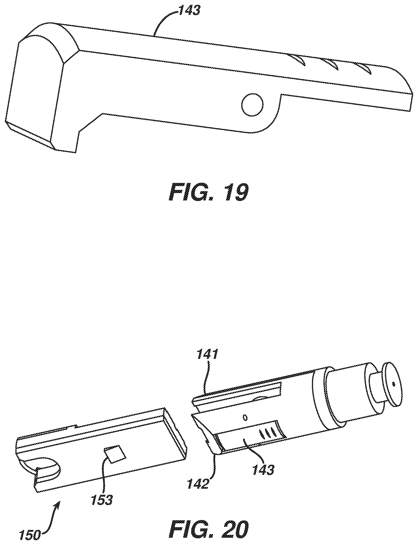
D00015

D00016

D00017

D00018
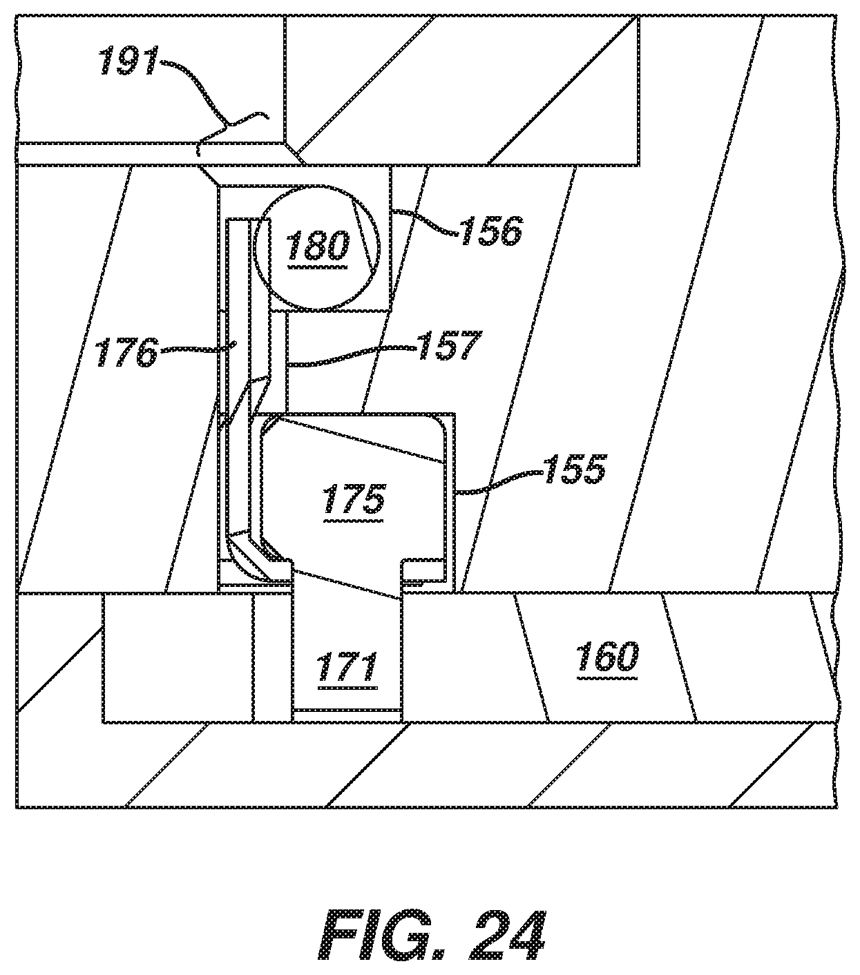
D00019

D00020

D00021

D00022
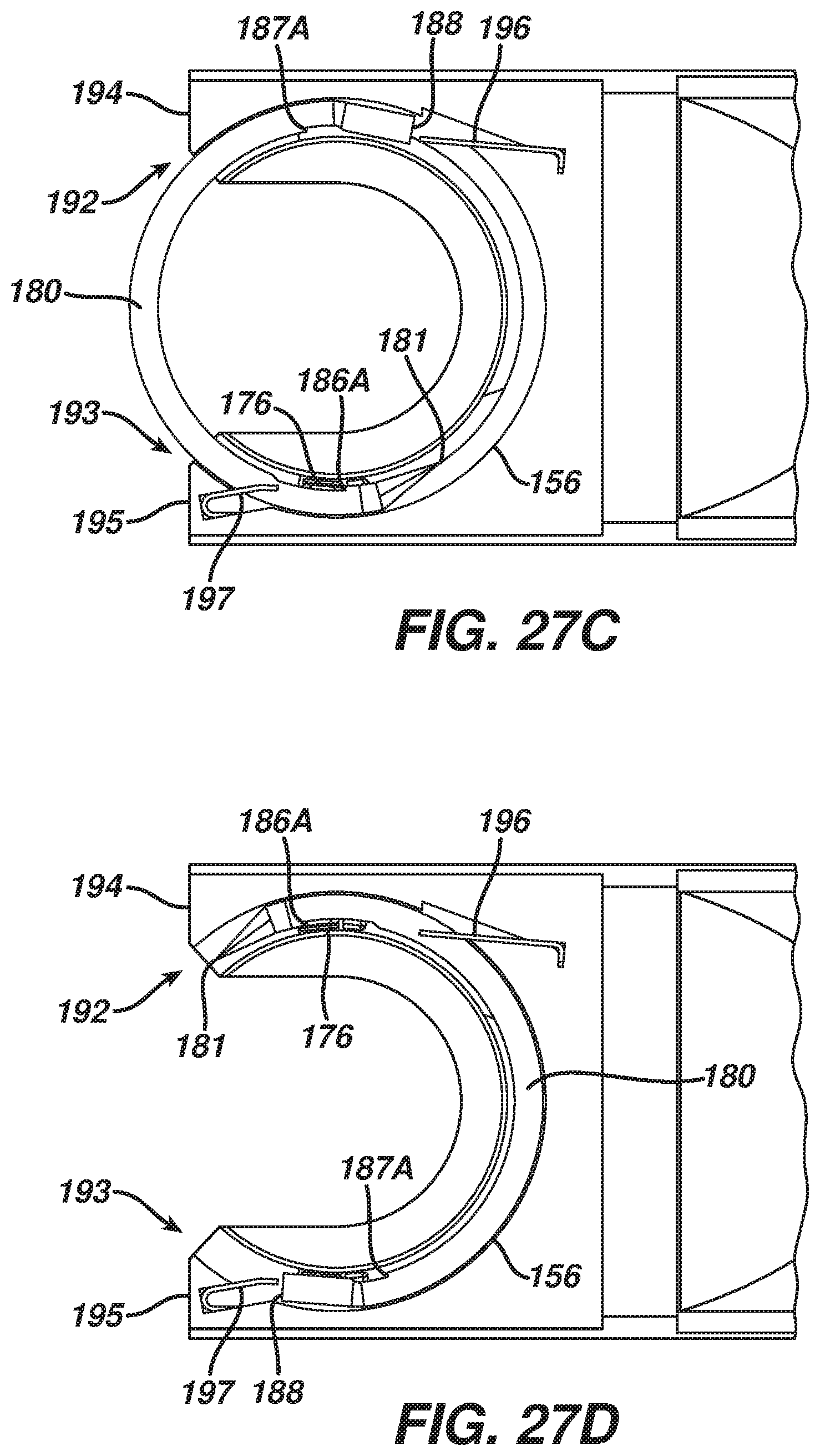
D00023

D00024

D00025

D00026

D00027

D00028

D00029

D00030

XML
uspto.report is an independent third-party trademark research tool that is not affiliated, endorsed, or sponsored by the United States Patent and Trademark Office (USPTO) or any other governmental organization. The information provided by uspto.report is based on publicly available data at the time of writing and is intended for informational purposes only.
While we strive to provide accurate and up-to-date information, we do not guarantee the accuracy, completeness, reliability, or suitability of the information displayed on this site. The use of this site is at your own risk. Any reliance you place on such information is therefore strictly at your own risk.
All official trademark data, including owner information, should be verified by visiting the official USPTO website at www.uspto.gov. This site is not intended to replace professional legal advice and should not be used as a substitute for consulting with a legal professional who is knowledgeable about trademark law.