Heat pump with dehumidification
Taras , et al. March 2, 2
U.S. patent number 10,935,260 [Application Number 16/213,338] was granted by the patent office on 2021-03-02 for heat pump with dehumidification. This patent grant is currently assigned to Climate Master, Inc.. The grantee listed for this patent is Climate Master, Inc.. Invention is credited to Puya Javidmand, Michael F. Taras.


| United States Patent | 10,935,260 |
| Taras , et al. | March 2, 2021 |
Heat pump with dehumidification
Abstract
Various embodiments of a heat pump system are disclosed to provide improved and flexible heat pump operation when dehumidification of the conditioned space is required. In one embodiment, a heat pump system includes a heat pump loop comprising a refrigerant circuit that fluidly interconnects (1) a compressor; (2) a source heat exchanger; (3) a source heat exchanger bypass circuit comprising a bypass valve; (4) a space heat exchanger; (5) a reversing valve positioned on the discharge side of the compressor; (6) a reheat circuit comprising a reheat heat exchanger; (7) first and second expansion devices; and (8) first and second expansion device bypass circuits configured to allow refrigerant to bypass the first and second expansion devices, respectively, where the first and second bypass circuits include first and second check valves, respectively; and (9) a 3-way valve configured to selectively direct refrigerant flow to the first expansion device, the reheat circuit, and the second expansion device.
| Inventors: | Taras; Michael F. (Oklahoma City, OK), Javidmand; Puya (Oklahoma City, OK) | ||||||||||
|---|---|---|---|---|---|---|---|---|---|---|---|
| Applicant: |
|
||||||||||
| Assignee: | Climate Master, Inc. (Oklahoma
City, OK) |
||||||||||
| Family ID: | 1000005397889 | ||||||||||
| Appl. No.: | 16/213,338 | ||||||||||
| Filed: | December 7, 2018 |
Prior Publication Data
| Document Identifier | Publication Date | |
|---|---|---|
| US 20190178509 A1 | Jun 13, 2019 | |
Related U.S. Patent Documents
| Application Number | Filing Date | Patent Number | Issue Date | ||
|---|---|---|---|---|---|
| 62597719 | Dec 12, 2017 | ||||
| Current U.S. Class: | 1/1 |
| Current CPC Class: | F24F 11/0008 (20130101); F24F 3/1405 (20130101); F24F 3/153 (20130101); F25B 41/20 (20210101); F25B 30/02 (20130101); F25B 41/31 (20210101); F25B 41/26 (20210101); F25B 13/00 (20130101); F25B 6/04 (20130101); F25B 40/02 (20130101); F25B 2313/005 (20130101); F24F 2003/1446 (20130101); F24F 2003/1452 (20130101); F25B 2313/0292 (20130101); F25B 2313/0212 (20130101); F25B 2400/0411 (20130101); F25B 2400/0403 (20130101) |
| Current International Class: | F24F 3/14 (20060101); F25B 6/04 (20060101); F25B 30/02 (20060101); F24F 11/00 (20180101); F25B 40/02 (20060101); F24F 3/153 (20060101); F25B 13/00 (20060101) |
References Cited [Referenced By]
U.S. Patent Documents
| 3460353 | August 1969 | Ogata |
| 3916638 | November 1975 | Schmidt |
| 3938352 | February 1976 | Schmidt |
| 4072187 | February 1978 | Lodge |
| 4173865 | November 1979 | Sawyer |
| 4179894 | December 1979 | Hughes |
| 4299098 | November 1981 | Derosier |
| 4399664 | August 1983 | Derosier |
| 4441901 | April 1984 | Endoh |
| 4493193 | January 1985 | Fisher |
| 4528822 | July 1985 | Glamm |
| 4538418 | September 1985 | Lawrence et al. |
| 4575001 | March 1986 | Oskarsson et al. |
| 4592206 | June 1986 | Yamazaki et al. |
| 4598557 | July 1986 | Robinson et al. |
| 4645908 | February 1987 | Jones |
| 4646538 | March 1987 | Blackshaw et al. |
| 4693089 | September 1987 | Bourne et al. |
| 4727727 | March 1988 | Reedy |
| 4766734 | August 1988 | Dudley |
| 4776180 | October 1988 | Patton et al. |
| 4796437 | January 1989 | James |
| 4798059 | January 1989 | Morita |
| 4835976 | June 1989 | Torrence |
| 4856578 | August 1989 | McCahill |
| 4893476 | January 1990 | Bos et al. |
| 4920757 | May 1990 | Gazes et al. |
| 4924681 | May 1990 | De Vit et al. |
| 4938032 | July 1990 | Mudford |
| 5038580 | August 1991 | Hart |
| 5044425 | September 1991 | Tatsumi |
| 5081848 | January 1992 | Rawlings et al. |
| 5088296 | February 1992 | Hamaoka |
| 5099651 | March 1992 | Fischer |
| 5136855 | August 1992 | Lenarduzzi |
| 5172564 | December 1992 | Reedy |
| 5187944 | February 1993 | Jarosch |
| 5224357 | July 1993 | Galiyano et al. |
| 5305822 | April 1994 | Kogetsu |
| 5309732 | May 1994 | Sami |
| 5323844 | June 1994 | Sumitani et al. |
| 5339890 | August 1994 | Rawlings |
| 5355688 | October 1994 | Rafalovich et al. |
| 5372016 | December 1994 | Rawlings |
| 5438846 | August 1995 | Datta |
| 5461876 | October 1995 | Dressler |
| 5465588 | November 1995 | McCahill et al. |
| 5477914 | December 1995 | Rawlings |
| 5497629 | March 1996 | Rafalovich et al. |
| 5507337 | April 1996 | Rafalovich et al. |
| 5533355 | July 1996 | Rawlings |
| 5564282 | October 1996 | Kaye |
| 5613372 | March 1997 | Beal et al. |
| 5619864 | April 1997 | Reedy |
| 5628200 | May 1997 | Pendergrass |
| 5651265 | July 1997 | Grenier |
| 5669224 | September 1997 | Lenarduzzi |
| 5689966 | November 1997 | Zess et al. |
| 5729985 | March 1998 | Yoshihara et al. |
| 5758514 | June 1998 | Genung et al. |
| 5802864 | September 1998 | Yarbrough et al. |
| 5927088 | July 1999 | Shaw |
| 6032472 | March 2000 | Heinrichs et al. |
| 6070423 | June 2000 | Hebert |
| 6082125 | July 2000 | Savtchenko |
| 6123147 | September 2000 | Pittman |
| 6149066 | November 2000 | Perry et al. |
| 6167715 | January 2001 | Hebert |
| 6227003 | May 2001 | Smolinsky |
| 6253564 | July 2001 | Yarbrough et al. |
| 6347527 | February 2002 | Bailey et al. |
| 6385983 | May 2002 | Sakki et al. |
| 6418745 | July 2002 | Ratliff |
| 6434960 | August 2002 | Rousseau |
| 6474087 | November 2002 | Lifson |
| 6536221 | March 2003 | James |
| 6655164 | December 2003 | Rogstam |
| 6662864 | December 2003 | Burk et al. |
| 6694750 | February 2004 | Lifson et al. |
| 6729151 | May 2004 | Thompson |
| 6751972 | June 2004 | Jungwirth |
| 6804975 | October 2004 | Park |
| 6817205 | November 2004 | Lifson et al. |
| 6826921 | December 2004 | Uselton |
| 6857285 | February 2005 | Hebert |
| 6892553 | May 2005 | Lifson et al. |
| 6915656 | July 2005 | Ratliff |
| 6931879 | August 2005 | Wiggs |
| 6938438 | September 2005 | Lifson et al. |
| 6941770 | September 2005 | Taras et al. |
| 7000423 | February 2006 | Lifson et al. |
| 7059151 | June 2006 | Taras et al. |
| 7114349 | October 2006 | Lifson et al. |
| 7150160 | December 2006 | Herbert |
| 7155922 | January 2007 | Harmon et al. |
| 7185505 | March 2007 | Kamimura |
| RE39597 | May 2007 | Rousseau |
| 7210303 | May 2007 | Zhang et al. |
| 7228707 | June 2007 | Lifson et al. |
| 7234311 | June 2007 | Lifson et al. |
| 7254955 | August 2007 | Otake et al. |
| 7263848 | September 2007 | Bhatti |
| 7272948 | September 2007 | Taras et al. |
| 7275385 | October 2007 | Abel et al. |
| 7325414 | February 2008 | Taras et al. |
| 7484374 | February 2009 | Pham et al. |
| 7617697 | November 2009 | McCaughan |
| 7654104 | February 2010 | Groll et al. |
| 7716943 | May 2010 | Seefeldt |
| 7770405 | August 2010 | Dillon |
| 7823404 | November 2010 | Hanson |
| 7845190 | December 2010 | Pearson |
| 7854137 | December 2010 | Lifson et al. |
| 7856834 | December 2010 | Haley |
| 7913501 | March 2011 | Ellis et al. |
| 7937960 | May 2011 | Matsui |
| 7958737 | June 2011 | Lifson et al. |
| 7975495 | July 2011 | Voorhis |
| 7975506 | July 2011 | James et al. |
| 7997092 | August 2011 | Lifson et al. |
| 8037713 | October 2011 | Haley et al. |
| 8074459 | December 2011 | Murakami et al. |
| 8079228 | December 2011 | Lifson et al. |
| 8079229 | December 2011 | Lifson et al. |
| 8082751 | December 2011 | Wiggs |
| 8136364 | March 2012 | Lifson et al. |
| 8191376 | June 2012 | Fox et al. |
| 8220531 | July 2012 | Murakami et al. |
| 8418482 | April 2013 | Bush et al. |
| 8418486 | April 2013 | Taras et al. |
| 8424326 | April 2013 | Mitra et al. |
| 8459052 | June 2013 | Bush et al. |
| 8528359 | September 2013 | Lifson et al. |
| 8561425 | October 2013 | Mitra et al. |
| 8650893 | February 2014 | Hanson |
| 8733429 | May 2014 | Harrison et al. |
| 8756943 | June 2014 | Chen et al. |
| 8769982 | July 2014 | Ignatiev et al. |
| 8984903 | March 2015 | Itoh |
| 9052125 | June 2015 | Dostal |
| 9562700 | February 2017 | Watanabe |
| 10072856 | September 2018 | Akin et al. |
| 10118462 | November 2018 | Kohigashi |
| 10119738 | November 2018 | Hammond et al. |
| 10345004 | July 2019 | Hern et al. |
| 2003/0221445 | December 2003 | Smolinsky |
| 2006/0010908 | January 2006 | Taras et al. |
| 2006/0218949 | October 2006 | Ellis et al. |
| 2006/0225445 | October 2006 | Lifson et al. |
| 2007/0074536 | April 2007 | Bai |
| 2007/0289319 | December 2007 | Kim et al. |
| 2007/0295477 | December 2007 | Mueller et al. |
| 2008/0016895 | January 2008 | Kim et al. |
| 2008/0041072 | February 2008 | Seefeldt |
| 2008/0173034 | July 2008 | Shaw |
| 2008/0196418 | August 2008 | Lifson et al. |
| 2008/0197206 | August 2008 | Murakami et al. |
| 2008/0209930 | September 2008 | Taras et al. |
| 2008/0256975 | October 2008 | Lifson et al. |
| 2008/0282718 | November 2008 | Beagle |
| 2008/0296396 | December 2008 | Corroy et al. |
| 2008/0302113 | December 2008 | Yin et al. |
| 2008/0302118 | December 2008 | Chen et al. |
| 2008/0302129 | December 2008 | Mosemann et al. |
| 2008/0307813 | December 2008 | Lifson et al. |
| 2009/0107656 | April 2009 | Marois |
| 2009/0208331 | August 2009 | Haley et al. |
| 2009/0294097 | December 2009 | Rini et al. |
| 2009/0314014 | December 2009 | Ericsson |
| 2010/0005831 | January 2010 | Vaisman et al. |
| 2010/0024470 | February 2010 | Lifson et al. |
| 2010/0058781 | March 2010 | Lifson et al. |
| 2010/0064710 | March 2010 | Slaughter |
| 2010/0064722 | March 2010 | Taras |
| 2010/0077788 | April 2010 | Lewis |
| 2010/0114384 | May 2010 | Maxwell |
| 2010/0132399 | June 2010 | Mitra et al. |
| 2010/0199715 | August 2010 | Lifson et al. |
| 2010/0251750 | October 2010 | Lifson et al. |
| 2010/0281894 | November 2010 | Huff |
| 2010/0287969 | November 2010 | Ueda et al. |
| 2010/0326100 | December 2010 | Taras et al. |
| 2011/0023515 | February 2011 | Kopko et al. |
| 2011/0036119 | February 2011 | Fujimoto et al. |
| 2011/0041523 | February 2011 | Taras et al. |
| 2011/0061413 | March 2011 | Setoguchi |
| 2011/0079032 | April 2011 | Taras |
| 2011/0088426 | April 2011 | Lochtefeld |
| 2011/0094248 | April 2011 | Taras et al. |
| 2011/0094259 | April 2011 | Lifson et al. |
| 2011/0132007 | June 2011 | Weyna et al. |
| 2011/0174014 | July 2011 | Scarcella et al. |
| 2011/0203299 | August 2011 | Jing et al. |
| 2011/0209490 | September 2011 | Mijanovic et al. |
| 2011/0259025 | October 2011 | Noh et al. |
| 2011/0289950 | December 2011 | Kim et al. |
| 2011/0289952 | December 2011 | Kim et al. |
| 2012/0011866 | January 2012 | Scarcella et al. |
| 2012/0067965 | March 2012 | Rajasekaran et al. |
| 2012/0103005 | May 2012 | Kopko et al. |
| 2012/0198867 | August 2012 | Ng et al. |
| 2012/0205077 | August 2012 | Zinger et al. |
| 2012/0247134 | October 2012 | Gurin |
| 2012/0291460 | November 2012 | Aoyagi |
| 2013/0014451 | January 2013 | Russell et al. |
| 2013/0031934 | February 2013 | Huff et al. |
| 2013/0098085 | April 2013 | Judge et al. |
| 2013/0104574 | May 2013 | Dempsey et al. |
| 2013/0180266 | July 2013 | Bois |
| 2013/0269378 | October 2013 | Wong |
| 2013/0305756 | November 2013 | Gomes et al. |
| 2014/0013782 | January 2014 | Kopko et al. |
| 2014/0013788 | January 2014 | Kopko et al. |
| 2014/0033753 | February 2014 | Lu et al. |
| 2014/0033755 | February 2014 | Wong |
| 2014/0053585 | February 2014 | Huff |
| 2014/0060101 | March 2014 | Styles et al. |
| 2014/0123689 | May 2014 | Ellis et al. |
| 2014/0245770 | September 2014 | Chen et al. |
| 2014/0260392 | September 2014 | Hawkins et al. |
| 2015/0052937 | February 2015 | Hung |
| 2015/0059373 | March 2015 | Maiello et al. |
| 2015/0204586 | July 2015 | Burg et al. |
| 2017/0010029 | January 2017 | Reytblat et al. |
| 2017/0227250 | August 2017 | Karamanos |
| 2018/0010829 | January 2018 | Taras et al. |
| 2018/0128506 | May 2018 | Taras et al. |
| 2018/0313555 | November 2018 | Henderson |
| 1178268 | Nov 1984 | CA | |||
| 1987397 | Jun 2007 | CN | |||
| 201944952 | Aug 2011 | CN | |||
| 102353126 | Feb 2012 | CN | |||
| 203231582 | Oct 2013 | CN | |||
| 103471275 | Dec 2013 | CN | |||
| 203396155 | Jan 2014 | CN | |||
| 203432025 | Feb 2014 | CN | |||
| 134015 | Mar 1985 | EP | |||
| 1983275 | Oct 2008 | EP | |||
| 2000016417 | Feb 2000 | JP | |||
| 2000274786 | Oct 2000 | JP | |||
| 2000314563 | Nov 2000 | JP | |||
| 2001248931 | Sep 2001 | JP | |||
| 100963221 | Jun 2010 | KR | |||
| 9600370 | Jan 1996 | WO | |||
| 2001/90663 | Nov 2001 | WO | |||
| 2006/033782 | Mar 2006 | WO | |||
| 2008/045086 | Apr 2008 | WO | |||
| 2008/048252 | Apr 2008 | WO | |||
| 2010/005918 | Jan 2010 | WO | |||
| 2010/054498 | May 2010 | WO | |||
| 2010/104709 | Sep 2010 | WO | |||
| 2013/142760 | Sep 2013 | WO | |||
| 2014/031559 | Feb 2014 | WO | |||
| 2014/031708 | Feb 2014 | WO | |||
Other References
|
"Heat pumps in residential and commercial buildings" http://www.heatpumpcentre.org/en/aboutheatpumps/heatpumpsinresidential/Si- dor/default.aspx (Accessed Apr. 20, 2011) (2 pages). cited by applicant . "Heat Pump Mechanics" http://www.geo4va.vt.edu/A3/A3.htm#A3sec3c (Accessed Apr. 20, 2011) (19pages). cited by applicant . Murphy et al., "Air-Source Integrated Heat Pump for Net-Zero-Energy Houses Technology Status Report," Oak Ridge National Laboratory, ORNL-TM-2007-112 (Jul. 2007) (93 pages). cited by applicant . Murphy et al., "Ground-Source Integrated Heat Pump for Net-Zero-Energy Houses Technology Status Report," Oak Ridge National Laboratory, ORNL-TM-2007-177 (Dec. 2007) (78 pages). cited by applicant . Korean Intellectual Property Office, International Search Report in International Application No. PCT/US2009/049734 (dated Jan. 20, 2010) (2 pages). cited by applicant . Korean Intellectual Property Office, International Search Report in International Application No. PCT/US2010/026010 (dated Sep. 28, 2010) (2 pages). cited by applicant . "134-XS and 134-S Series Compressors ECOnomizer (EA-12-03-E)," 134-XS and 134-S series--Application and Maintenance Manual, Technical report EA1203E, RefComp Refrigerant Compressors, undated but believed to be publicly available at least as early as Mar. 2014 (4 pages). cited by applicant . B.P. Rasmussen et al., "Model-Driven System Identification of Transcritical Vapor Compression Systems," IEEE Transactions on Control Systems Technology, May 2005, pp. 444-451, vol. 13 (8 pages). cited by applicant . "Economized Vapor Injection (EVI) Compressors," Emerson Climate Technologies Application Engineering Bulletin AE4-1327 R2, Revised Sep. 2006 (9 pages). cited by applicant . Ekaterina VI Nogradova, "Economizers in Chiller Systems," Bachelors Thesis, Mikkelin Ammattikorkeakoulu, Nov. 2012 (50 pages). cited by applicant . "Enhanced Vapour Injection (EVI) for ZH*KVE Scroll Compressors," Emerson Climate Technologies--Technical Information, C7.4.3/1107-0512/E, May 2012 (10 pages). cited by applicant . Haraldsson et al., "Measurement of Performance and Evaluation of a Heat Pump--with Scroll Compressor EVI and Economizer," Lunds Institute of Technology, 2006 (4 pages). cited by applicant . John P. Elson et al., "Scroll Technology: An Overview of Past, Present and Future Developments," International Compressor Engineering Conference, 2008, Paper 1871 (9 pages). cited by applicant . Lund et al., "Geothermal (Ground-Source Heat Pumps--A World Overview," GHC Bulletin, Sep. 2004 (edited and updated version of the article from Renewal Energy World, (Jul.-Aug. 2003), vol. 6 No. 4) (10 pages). cited by applicant . Tolga N. Aynur, "Variable Refrigerant Flow Systems: A Review, Energy and Buildings," Jan. 2010, pp. 1106-1112, vol. 42 (7 pages). cited by applicant . Wei Yang et al., "The Design Method of U-Bend Geothermal Heat Exchanger of DX-GCHP in Cooling Model," IEEE, 2011, pp. 3635-3637 (English Abstract) (3 pages). cited by applicant . International Search Report and Written Opinion issued in International Application No. PCT/US2013/033433 dated Aug. 9, 2013 (11 Pages). cited by applicant . International Preliminary Report on Patentability issued in International Application No. PCT/US2013/033433 dated Sep. 23, 2014 (7 Pages). cited by applicant . Third Party Submission dated Nov. 10, 2014 filed in U.S. Appl. No. 13/848,342 (13 Pages). cited by applicant . Honeywell, VFF1, VFF2, VFF3, VFF6 Resilient Seat Butterfly Valves with Flanged Connections Jan. 2013, p. 1, 1st column, last paragraph. (Year: 2013) (20 pages). cited by applicant . Taras, Michael F., "Reheat Which Concept is Best," ASHRAE Journal: 35-40 (Dec. 2004) (7 pages). cited by applicant. |
Primary Examiner: Nieves; Nelson J
Attorney, Agent or Firm: Neal, Gerber & Eisenberg LLP Williams; Thomas E.
Parent Case Text
CROSS REFERENCE TO RELATED APPLICATIONS
This application claims the benefit of U.S. Provisional Patent Application Ser. No. 62/597,719, filed Dec. 12, 2017, which is incorporated by reference herein in its entirety.
Claims
The invention claimed is:
1. A heat pump system for conditioning air in a space, comprising: a heat pump loop comprising a refrigerant circuit that fluidly interconnects: a variable speed compressor having a discharge outlet port and an inlet suction port; a refrigerant-to-liquid source heat exchanger operable as either a condenser or an evaporator for exchanging heat with a source liquid; a source heat exchanger bypass circuit comprising a bi-directional bypass valve to modulate refrigerant flow through the source heat exchanger; a refrigerant-to-air space heat exchanger operable as either an evaporator or a condenser for cooling or heating the air in the space; a reversing valve positioned on the discharge side of the compressor and configured to alternately direct refrigerant flow from the discharge outlet port of the compressor to one of the source heat exchanger and the space heat exchanger and to alternately return flow from the other of the source heat exchanger and the space heat exchanger to the suction inlet port of the compressor; a reheat circuit comprising a reheat heat exchanger to reheat the air when the system is in a dehumidification mode, and operable to act as an auxiliary condenser when the system is in a heating mode, wherein the space heat exchanger and the reheat heat exchanger are positioned in an air flow path for conditioning the air in the space; first and second electronic bi-directional expansion devices; first and second expansion device bypass circuits configured to allow refrigerant to bypass the first and second expansion devices, respectively, the first and second bypass circuits comprising first and second check valves, respectively, to control a direction of refrigerant flow in the first and second bypass circuits; and a 3-way valve configured to selectively direct refrigerant flow (i) to the first expansion device from the reheat circuit, (ii) to the reheat circuit from the first expansion device bypass circuit, and (iii) to the second expansion device from the first expansion device bypass circuit, wherein the first expansion device is positioned between the source heat exchanger and the 3-way valve, the second expansion device is positioned between the reheat circuit and the space heat exchanger, and the reheat circuit includes a bi-directional reheat bypass valve that loins an upstream leg and a downstream leg of the reheat heat exchanger and is positioned between the second expansion device and the 3-way valve to modulate refrigerant flow through the reheat heat exchanger.
2. The heat pump system of claim 1, including a liquid pump associated with the source heat exchanger and the pump is a variable capacity pump.
3. The heat pump system of claim 1, including a fan associated with the space heat exchanger and the fan is a variable airflow fan.
4. The heat pump system of claim 1, including a controller comprising a processor and memory on which one or more software programs are stored, the controller configured to control operation of the reversing valve, the bypass valve, the 3-way valve, the first and second expansion devices, the compressor, a liquid pump for circulating water or brine solution through the source heat exchanger, and a fan for flowing air over the space heat exchanger and the reheat heat exchanger.
5. The heat pump system of claim 4, wherein to operate the system in a cooling mode, the controller is configured to: close the bypass valve to cause refrigerant flow through the source heat exchanger; close the first expansion device to cause refrigerant flow through the first expansion device bypass circuit and the first check valve; control the 3-way valve to inactivate the reheat circuit and to cause refrigerant flow to the second expansion device; control an opening of the second expansion device to cause refrigerant flow through the second expansion device, and thereafter, the space heat exchanger, wherein an orientation of the second check valve prohibits flow of refrigerant through the second expansion device bypass circuit; and control the reversing valve to cause refrigerant flow from the discharge outlet port of the compressor to the source heat exchanger and to return flow from the space heat exchanger to the suction inlet port of the compressor.
6. The heat pump system of claim 4, wherein to operate the system in the dehumidification mode, the controller is configured to: control an opening of the bypass valve to modulate refrigerant flow through the source heat exchanger and through the source heat exchanger bypass circuit; close the first expansion device to cause refrigerant flow through the first expansion device bypass circuit and the first check valve; control the 3-way valve to cause refrigerant flow from the first expansion device bypass circuit to the reheat circuit, and thereafter, to the second expansion device; control an opening of the second expansion device to cause refrigerant flow through the second expansion device, and thereafter, the space heat exchanger, wherein an orientation of the second check valve prohibits flow of refrigerant through the second expansion device bypass circuit; and control the reversing valve to cause refrigerant flow from the discharge outlet port of the compressor to the source heat exchanger and to return flow from the space heat exchanger to the suction inlet port of the compressor.
7. The heat pump system of claim 6, wherein the controller is configured to control an opening of a reheat bypass valve positioned along the reheat circuit to modulate refrigerant flow through the reheat heat exchanger.
8. The heat pump system of claim 4, wherein to operate the system in the heating mode, the controller is configured to: control the reversing valve to cause refrigerant flow from the discharge outlet port of the compressor to the space heat exchanger and to return flow from the source heat exchanger to the suction inlet port of the compressor; close the second expansion device to cause refrigerant flow through the second expansion device bypass circuit and the second check valve, and thereafter, the reheat heat exchanger; control the 3-way valve to cause refrigerant flow in the reheat circuit, and thereafter, to the first expansion device; control an opening of the first expansion device to cause refrigerant flow through the first expansion device, wherein an orientation of the first check valve prohibits flow of refrigerant through the first expansion device bypass circuit; and close the bypass valve to cause refrigerant flow through the source heat exchanger.
9. The heat pump system of claim 8, wherein the controller is configured to control an opening of a reheat bypass valve positioned along the reheat circuit to modulate refrigerant flow through the reheat heat exchanger.
10. A heat pump system for conditioning air in a space, comprising: a heat pump loop comprising a refrigerant circuit that fluidly interconnects: a compressor having a discharge outlet port and an inlet suction port; a source heat exchanger operable as either a condenser or an evaporator for exchanging heat with a source liquid; a source heat exchanger bypass circuit comprising a bypass valve to modulate refrigerant flow through the source heat exchanger; a space heat exchanger operable as either an evaporator or a condenser for cooling or heating the air in the space; a reversing valve positioned on the discharge side of the compressor and configured to alternately direct refrigerant flow from the discharge outlet port of the compressor to one of the source heat exchanger and the space heat exchanger and to alternately return flow from the other of the source heat exchanger and the space heat exchanger to the suction inlet port of the compressor; a reheat circuit comprising a reheat heat exchanger to reheat the air when the system is in a dehumidification mode, and operable to act as an auxiliary condenser when the system is in a heating mode, wherein the space heat exchanger and the reheat heat exchanger are positioned in an air flow path for conditioning the air in the space; first and second electronic bi-directional expansion devices; first and second expansion device bypass circuits configured to allow refrigerant to bypass the first and second expansion devices, respectively, the first and second bypass circuits comprising first and second check valves, respectively, to control a direction of refrigerant flow in the first and second bypass circuits; and a 3-way valve configured to selectively direct refrigerant flow (i) to the first expansion device from the reheat circuit when the heat pump loop is in a heating mode, (ii) to the reheat circuit from the first expansion device bypass circuit when the heat pump loop is in a dehumidification mode, and (iii) to the second expansion device from the first expansion device bypass circuit when the heat pump loop is in a cooling mode, wherein the reheat circuit includes a bi-directional reheat bypass valve that joins an upstream leg to a downstream leg of the reheat heat exchanger and is positioned between the second expansion device and the 3-way valve to modulate refrigerant flow through the reheat heat exchanger.
11. The heat pump system of claim 10, wherein the compressor is a variable speed compressor.
12. The heat pump system of claim 10, including a liquid pump associated with the source heat exchanger and the pump is a variable capacity pump.
13. The heat pump system of claim 10, including a variable airflow fan configured to blow air across the space heat exchanger.
14. The heat pump system of claim 10, wherein the bypass valve is bi-directional.
Description
BACKGROUND
The instant disclosure relates generally to heating, ventilation, and air conditioning systems and methods and, more particularly but without limitation, to heat pump systems.
SUMMARY
Disclosed are various embodiments of heat pump systems and methods of operating the heat pump systems for conditioning air in a space.
In one embodiment, a heat pump system for conditioning air in a space includes a heat pump loop comprising a refrigerant circuit that fluidly interconnects: (1) a compressor having a discharge outlet port and an inlet suction port; (2) a source heat exchanger operable as either a condenser or an evaporator; (3) a source heat exchanger bypass circuit comprising a bypass valve to modulate refrigerant flow through the source heat exchanger; (4) a space heat exchanger operable as either an evaporator or a condenser for cooling or heating the air in the space; (5) a reversing valve positioned on the discharge side of the compressor and configured to alternately direct refrigerant flow from the discharge outlet port of the compressor to one of the source heat exchanger and the space heat exchanger and to alternately return flow from the other of the source heat exchanger and the space heat exchanger to the suction inlet port of the compressor; (6) a reheat circuit comprising a reheat heat exchanger to reheat the air when the system is in a dehumidification mode, and operable to act as an auxiliary condenser when the system is in a heating mode, where the space heat exchanger and the reheat heat exchanger are positioned in an air flow path for conditioning the air in the space; (7) first and second expansion devices; and (8) first and second expansion device bypass circuits configured to allow refrigerant to bypass the first and second expansion devices, respectively, the first and second bypass circuits comprising first and second check valves, respectively, to control a direction of refrigerant flow in the first and second bypass circuits; and (9) a 3-way valve configured to selectively direct refrigerant flow to the first expansion device, the reheat circuit, and the second expansion device.
The compressor may be a variable capacity compressor. The heat pump system may include a liquid pump associated with the source heat exchanger and the pump may be a variable capacity pump. The heat pump system may include a fan associated with the space heat exchanger and the fan may be a variable airflow fan. The bypass valve may be bi-directional. The first and second expansion devices may be fixed orifice devices, mechanical valves, or electronic valves. The first expansion device may be positioned between the source heat exchanger and the 3-way valve. The second expansion device may be positioned between the reheat circuit and the space heat exchanger. The reheat circuit may include a reheat bypass valve to modulate refrigerant flow through the reheat heat exchanger.
The heat pump system may include a controller comprising a processor and memory on which one or more software programs are stored, the controller configured to control operation of the reversing valve, the bypass valve, the 3-way valve, and the first and second expansion devices, the compressor, the liquid pump for circulating water or brine solution through the source heat exchanger, and the fan for flowing air over the space heat exchanger and the reheat heat exchanger.
To operate the system in a cooling mode, the controller may be configured to: (a) close the bypass valve to cause refrigerant flow through the source heat exchanger; (b) close the first expansion device to cause refrigerant flow through the first expansion device bypass circuit and the first check valve; (c) control the 3-way valve to inactivate the reheat circuit and to cause refrigerant flow to the second expansion device; (d) control an opening of the second expansion device to cause refrigerant flow through the second expansion device, and thereafter, the space heat exchanger, wherein an orientation of the second check valve prohibits flow of refrigerant through the second expansion device bypass circuit; and (e) control the reversing valve to cause refrigerant flow from the discharge outlet port of the compressor to the source heat exchanger and to return flow from the space heat exchanger to the suction inlet port of the compressor.
To operate the system in the dehumidification mode, the controller may be configured to: (a) control an opening of the bypass valve to modulate refrigerant flow through the source heat exchanger and through the source heat exchanger bypass circuit; (b) close the first expansion device to cause refrigerant flow through the first expansion device bypass circuit and the first check valve; (c) control the 3-way valve to cause refrigerant flow from the first expansion device bypass circuit to the reheat circuit, and thereafter, to the second expansion device; (d) control an opening of the second expansion device to cause refrigerant flow through the second expansion device, and thereafter, the space heat exchanger, wherein an orientation of the second check valve prohibits flow of refrigerant through the second expansion device bypass circuit; and (e) control the reversing valve to cause refrigerant flow from the discharge outlet port of the compressor to the source heat exchanger and to return flow from the space heat exchanger to the suction inlet port of the compressor. The controller may be configured to control an opening of a reheat bypass valve positioned along the reheat circuit to modulate refrigerant flow through the reheat heat exchanger.
To operate the system in the heating mode, the controller may be configured to: (a) control the reversing valve to cause refrigerant flow from the discharge outlet port of the compressor to the space heat exchanger and to return flow from the source heat exchanger to the suction inlet port of the compressor; (b) close the second expansion device to cause refrigerant flow through the second expansion device bypass circuit and the second check valve, and thereafter, the reheat heat exchanger; (c) control the 3-way valve to cause refrigerant flow in the reheat circuit, and thereafter, to the first expansion device; (d) control an opening of the first expansion device to cause refrigerant flow through the first expansion device, wherein an orientation of the first check valve prohibits flow of refrigerant through the first expansion device bypass circuit; and (e) close the bypass valve to cause refrigerant flow through the source heat exchanger. The controller may be configured to control an opening of a reheat bypass valve positioned along the reheat circuit to modulate refrigerant flow through the reheat heat exchanger.
In one embodiment, a method of conditioning air in a space is disclosed, comprising the steps of: (1) providing a heat pump loop comprising a refrigerant circuit that fluidly interconnects (a) a compressor having a discharge outlet port and an inlet suction port; (b) a source heat exchanger operable as either a condenser or an evaporator; (c) a source heat exchanger bypass circuit comprising a bypass valve to modulate refrigerant flow through the source heat exchanger; (d) a space heat exchanger operable as either an evaporator or a condenser for cooling or heating the air in the space; (e) a reversing valve positioned on the discharge side of the compressor and configured to alternately direct refrigerant flow from the discharge outlet port of the compressor to one of the source heat exchanger and the space heat exchanger and to alternately return flow from the other of the source heat exchanger and the space heat exchanger to the suction inlet port of the compressor; (f) a reheat circuit comprising a reheat heat exchanger to reheat the air when the system is in a dehumidification mode, and operable to act as an auxiliary condenser when the system is in a heating mode, wherein the space heat exchanger and the reheat heat exchanger are positioned in an air flow path for conditioning the air in the space; (g) first and second expansion devices; (h) first and second expansion device bypass circuits configured to allow refrigerant to bypass the first and second expansion devices, respectively, the first and second bypass circuits comprising first and second check valves, respectively, to control a direction of refrigerant flow in the first and second bypass circuits; (i) a 3-way valve configured to selectively direct refrigerant flow to the first expansion device, the reheat circuit, and the second expansion device; and (2) operating a control system configured to operate the heat pump loop in a plurality of modes in response to air conditioning demands in the space, wherein the plurality of modes includes a cooling mode, the heating mode, and the dehumidification mode.
In connection with the foregoing method, the compressor may be a variable capacity compressor; the bypass valve may be bi-directional; the heat pump system may include a liquid pump associated with the source heat exchanger and the pump may be a variable capacity pump; the heat pump system may include a fan associated with the space heat exchanger and the fan may be a variable airflow fan; the first and second expansion devices may be fixed orifice devices, mechanical valves, or electronic valves; the first expansion device may be positioned between the source heat exchanger and the 3-way valve; the second expansion device may be positioned between the reheat circuit and the space heat exchanger; the reheat circuit may include a reheat bypass valve to modulate refrigerant flow through the reheat heat exchanger; and the reheat circuit may include a reheat bypass valve to modulate refrigerant flow through the reheat heat exchanger.
The control system may include a controller comprising a processor and memory on which one or more software programs are stored, the controller configured to control operation of the reversing valve, the bypass valve, the 3-way valve, and the first and second expansion devices, the compressor, the liquid pump for circulating water or brine solution through the source heat exchanger, and the fan for flowing air over the space heat exchanger and the reheat heat exchanger.
Operating the controller in the cooling mode may include the steps of: (i) closing the bypass valve to cause refrigerant flow through the source heat exchanger; (ii) closing the first expansion device to cause refrigerant flow through the first expansion device bypass circuit and the first check valve; (iii) controlling respective openings in the 3-way valve to inactivate the reheat circuit and to cause refrigerant flow to the second expansion device; (iv) controlling an opening of the second expansion device to cause refrigerant flow through the second expansion device, and thereafter, the space heat exchanger, wherein an orientation of the second check valve prohibits flow of refrigerant through the second expansion device bypass circuit; and (v) controlling the reversing valve to cause refrigerant flow from the discharge outlet port of the compressor to the source heat exchanger and to return flow from the space heat exchanger to the suction inlet port of the compressor.
Operating the controller in the dehumidification mode may include the steps of: (i) controlling an opening of the bypass valve to modulate refrigerant flow through the source heat exchanger and through the source heat exchanger bypass circuit; (ii) closing the first expansion device to cause refrigerant flow through the first expansion device bypass circuit and the first check valve; (iii) controlling respective openings in the 3-way valve to cause refrigerant flow from the second expansion device bypass circuit to the reheat circuit, and thereafter, to the second expansion device; (iv) controlling an opening of the second expansion device to cause refrigerant flow through the second expansion device, and thereafter, the space heat exchanger, wherein an orientation of the second check valve prohibits flow of refrigerant through the second expansion device bypass circuit; and (v) controlling the reversing valve to cause refrigerant flow from the discharge outlet port of the compressor to the source heat exchanger and to return flow from the space heat exchanger to the suction inlet port of the compressor. The method may include the step of controlling an opening of a reheat bypass valve positioned along the reheat circuit to modulate refrigerant flow through the reheat heat exchanger.
Operating the controller in the heating mode may include the steps of: (i) controlling the reversing valve to cause refrigerant flow from the discharge outlet port of the compressor to the space heat exchanger and to return flow from the source heat exchanger to the suction inlet port of the compressor; (ii) closing the second expansion device to cause refrigerant flow through the second expansion device bypass circuit and the second check valve, and thereafter, the reheat heat exchanger; (iii) controlling respective openings in the 3-way valve to cause refrigerant flow in the reheat circuit, and thereafter, to the first expansion device; (iv) controlling an opening of the first expansion device to cause refrigerant flow through the first expansion device, wherein an orientation of the first check valve prohibits flow of refrigerant through the first expansion device bypass circuit; and (v) closing the bypass valve to cause refrigerant flow through the source heat exchanger. The method may include the step of controlling an opening of a reheat bypass valve positioned along the reheat circuit to modulate refrigerant flow through the reheat heat exchanger.
In another embodiment, a heat pump system for conditioning air in a space is disclosed, comprising a heat pump loop comprising a refrigerant circuit that fluidly interconnects: (1) a compressor having a discharge outlet port and an inlet suction port; (2) a source heat exchanger operable as either a condenser or an evaporator; (3) a space heat exchanger operable as either an evaporator or a condenser for cooling or heating the air in the space; (4) an expansion device positioned between the source heat exchanger and the space heat exchanger; (5) a reheat circuit comprising a reheat heat exchanger to reheat the air when the system is in a dehumidification mode, and operable to act as an auxiliary condenser when the system is in a heating mode, wherein the space heat exchanger and the reheat heat exchanger are positioned in an air flow path for conditioning the air in the space; (6) a reversing valve to alternately direct refrigerant flow to one of the source heat exchanger and the space heat exchanger and to alternately return flow from the other of the source heat exchanger and the space heat exchanger to the suction inlet port of the compressor; and (7) a 3-way valve positioned downstream of the compressor and configured to selectively direct refrigerant flow to the reversing valve and the reheat heat exchanger.
The compressor may be a variable capacity compressor. The heat pump system may include a liquid pump associated with the source heat exchanger and the pump may be a variable capacity pump. The heat pump system may include a fan associated with the space heat exchanger and the fan may be a variable airflow fan. The expansion device may be a fixed orifice device, a mechanical valve, or an electronic valve. The reheat circuit may include a reheat bypass valve to modulate refrigerant flow through the reheat heat exchanger. The reheat bypass valve may be bi-directional. The reheat circuit may include a shutoff valve positioned downstream of the reheat heat exchanger and upstream of the reversing valve.
The heat pump system may include a controller comprising a processor and memory on which one or more software programs are stored. The controller may be configured to control operation of the reversing valve, the 3-way valve, the shutoff valve, the expansion device, the compressor, the liquid pump for circulating water or brine solution through the source heat exchanger, and the fan for flowing air over the space heat exchanger and the reheat heat exchanger.
To operate the system in a cooling mode, the controller may be configured to: (a) control the 3-way valve and the shutoff valve to inactivate the reheat circuit and to cause refrigerant flow from the discharge port of the compressor to the 3-way valve, thereafter the reversing valve, and thereafter the source heat exchanger; (b) control an opening of the expansion device to cause refrigerant flow from the source heat exchanger to the expansion device, and thereafter the space heat exchanger; and (c) control the reversing valve to cause refrigerant flow from the 3-way valve to the source heat exchanger and to return flow from the space heat exchanger to the suction inlet port of the compressor.
To operate the system in the dehumidification mode, the controller may be configured to: (a) control the 3-way valve and the shutoff valve to activate the reheat circuit and to cause refrigerant flow from the discharge port of the compressor to the 3-way valve, thereafter the reheat heat exchanger, thereafter the shutoff valve, thereafter, the reversing valve, and thereafter, the source heat exchanger; (b) control an opening of the expansion device to cause refrigerant flow from the source heat exchanger to the expansion device, and thereafter the space heat exchanger; and (c) control the reversing valve to cause refrigerant flow from the reheat circuit to the source heat exchanger and to return flow from the space heat exchanger to the suction inlet port of the compressor. The controller may be configured to control an opening of a reheat bypass valve positioned along the reheat circuit to modulate refrigerant flow through the reheat heat exchanger
To operate the system in the heating mode, the controller may be configured to: (a) control the 3-way valve and the shutoff valve to activate the reheat circuit and to cause refrigerant flow from the discharge port of the compressor to the 3-way valve, thereafter the reheat heat exchanger, thereafter the shutoff valve, thereafter, the reversing valve, and thereafter, the space heat exchanger; (b) control an opening of the expansion device to cause refrigerant flow from the space heat exchanger to the expansion device, and thereafter the source heat exchanger; and (c) control the reversing valve to cause refrigerant flow from the reheat circuit to the space heat exchanger and to return flow from the source heat exchanger to the suction inlet port of the compressor. The controller may be configured to control an opening of a reheat bypass valve positioned along the reheat circuit to modulate refrigerant flow through the reheat heat exchanger.
In another embodiment, a heat pump system for conditioning air in a space is disclosed comprising a heat pump loop comprising a refrigerant circuit that fluidly interconnects: (1) a compressor having a discharge outlet port and an inlet suction port; (2) a source heat exchanger operable as either a condenser or an evaporator; (3) a source heat exchanger bypass circuit comprising a source heat exchanger bypass valve to modulate refrigerant flow through the source heat exchanger; (4) a space heat exchanger operable as either an evaporator or a condenser for cooling or heating the air in the space; (5) a reversing valve positioned on the discharge side of the compressor and configured to alternately direct refrigerant flow from the discharge outlet port of the compressor to one of the source heat exchanger and the space heat exchanger and to alternately return flow from the other of the source heat exchanger and the space heat exchanger to the suction inlet port of the compressor; (6) a reheat heat exchanger to reheat the air when the system is in a dehumidification mode, and operable to act as an auxiliary condenser when the system is in a heating mode and as an auxiliary evaporator when the system is in a cooling mode, wherein the space heat exchanger and the reheat heat exchanger are positioned in an air flow path for conditioning the air in the space; (7) first and second expansion devices; and (8) first and second expansion device bypass circuits configured to allow refrigerant to bypass the first and second expansion devices, respectively, the first and second expansion device bypass circuits comprising first and second expansion device bypass valves, respectively, where the first expansion device is positioned between the source heat exchanger and the reheat heat exchanger and the second expansion device is positioned between the reheat heat exchanger and the space heat exchanger.
The compressor may be a variable capacity compressor. The heat pump system may include a liquid pump associated with the source heat exchanger and the pump is a variable capacity pump. The heat pump system may include a fan associated with the space heat exchanger and the fan may be a variable airflow fan. The second expansion device bypass valve may be bi-directional. The second expansion device bypass circuit may be positioned between the reheat heat exchanger and the space heat exchanger. The first and second expansion devices may be fixed orifice devices, mechanical valves, or electronic valves.
The heat pump system may include a controller comprising a processor and memory on which one or more software programs are stored. The controller may be configured to control operation of the reversing valve, the source heat exchanger bypass valve, the first and second expansion devices, the first and second expansion device bypass valves, the compressor, the liquid pump for circulating water or brine solution through the source heat exchanger, and the fan for flowing air over the space heat exchanger and the reheat heat exchanger.
To operate the system in a cooling mode, the controller may be configured to: (a) close the source heat exchanger bypass valve to cause refrigerant flow through the source heat exchanger; (b) close the first expansion device bypass valve to cause refrigerant flow through the first expansion device and then through the reheat heat exchanger; (c) close the second expansion device to cause refrigerant flow through the second expansion device bypass circuit and then through the space heat exchanger; and (d) control the reversing valve to cause refrigerant flow from the discharge outlet port of the compressor to the source heat exchanger and to return flow from the space heat exchanger to the suction inlet port of the compressor.
To operate the system in the dehumidification mode, the controller may be configured to: (a) control an opening of the source heat exchanger bypass valve to modulate refrigerant flow through the source heat exchanger and through the source heat exchanger bypass circuit; (b) close the first expansion device to cause refrigerant flow through the first expansion device bypass circuit and then through the reheat heat exchanger; (c) close the second expansion device bypass valve to cause refrigerant flow through the second expansion device; (d) control an opening of the second expansion device to modulate refrigerant flow from the reheat heat exchanger through the second expansion device, and thereafter, the space heat exchanger; and (e) control the reversing valve to cause refrigerant flow from the discharge outlet port of the compressor to the source heat exchanger and to return flow from the space heat exchanger to the suction inlet port of the compressor.
To operate the system in the heating mode, the controller may be configured to: (a) close the source heat exchanger bypass valve to cause refrigerant flow through the source heat exchanger; (b) close the first expansion device bypass valve to cause refrigerant flow through the first expansion device and then through the source heat exchanger; (c) close the second expansion device to cause refrigerant flow through the second expansion device bypass circuit and then through the reheat heat exchanger; and (d) control the reversing valve to cause refrigerant flow from the discharge outlet port of the compressor to the space heat exchanger and to return flow from the source heat exchanger to the suction inlet port of the compressor. The controller may be also configured to control an opening of the second expansion device bypass valve to modulate flow through the space heat exchanger and the reheat heat exchanger.
BRIEF DESCRIPTION OF THE DRAWINGS
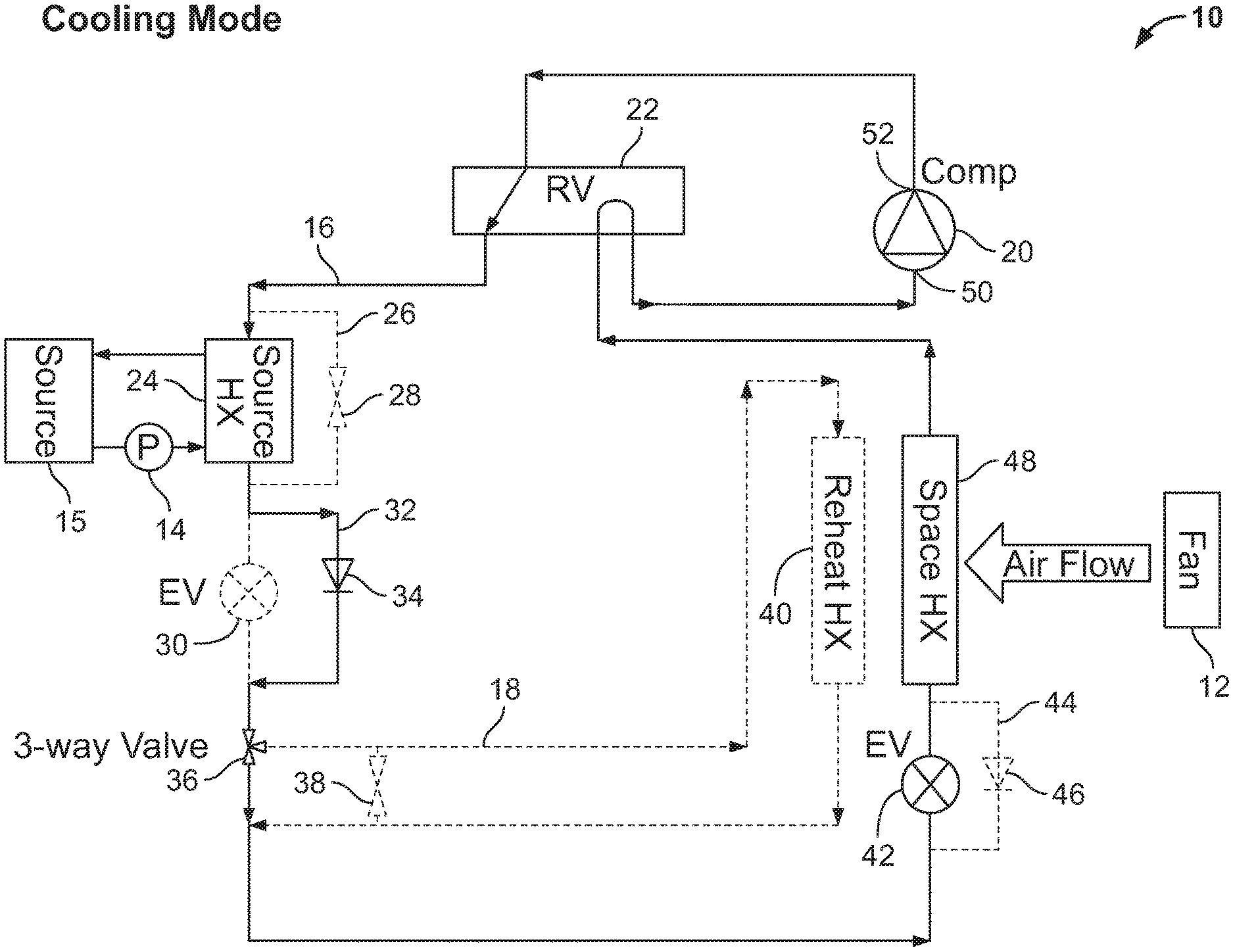
FIG. 1 is a schematic showing an embodiment of a heat pump system of the instant disclosure in a cooling mode.
FIG. 2 is a schematic showing the embodiment of FIG. 1 in a dehumidification mode.
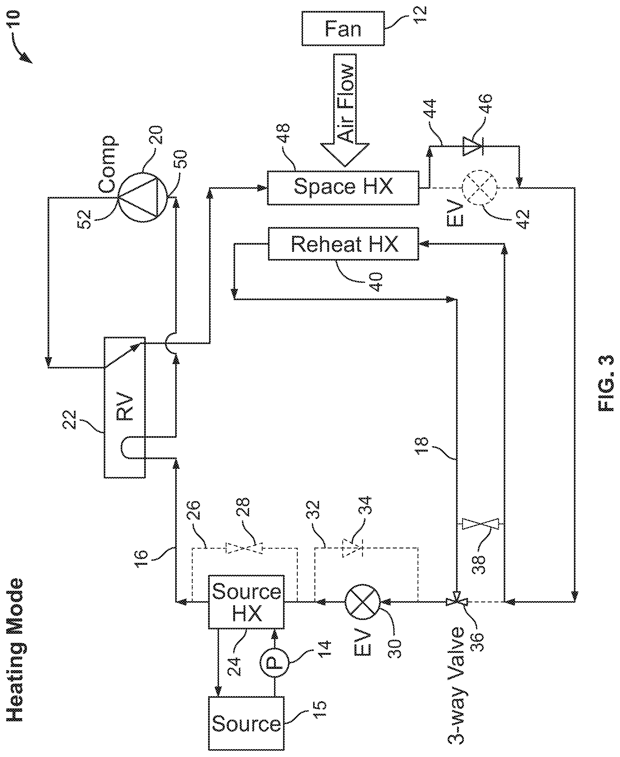
FIG. 3 is a schematic showing the embodiment of FIG. 1 in a heating mode.
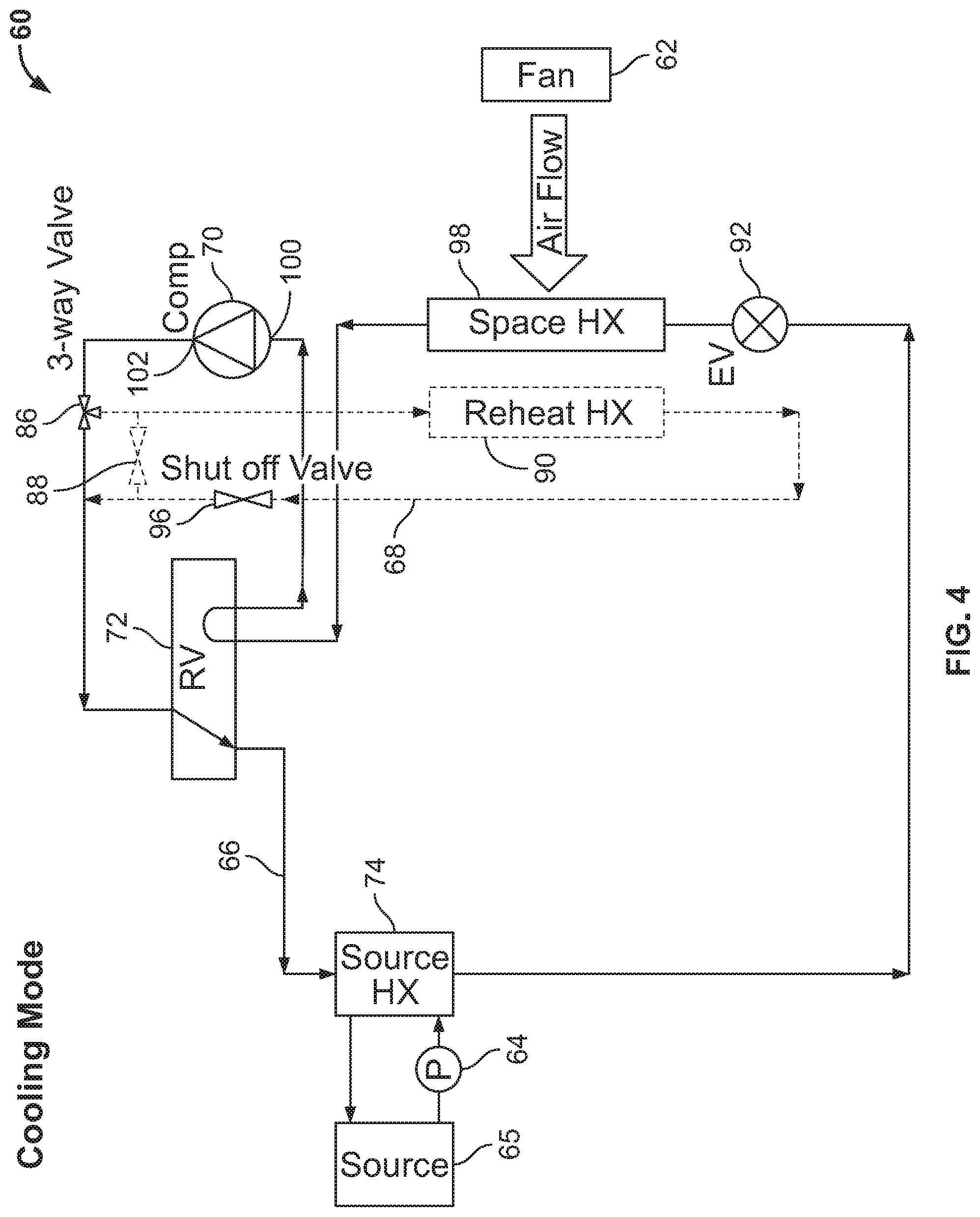
FIG. 4 is a schematic showing another embodiment of a heat pump system of the instant disclosure in a cooling mode.
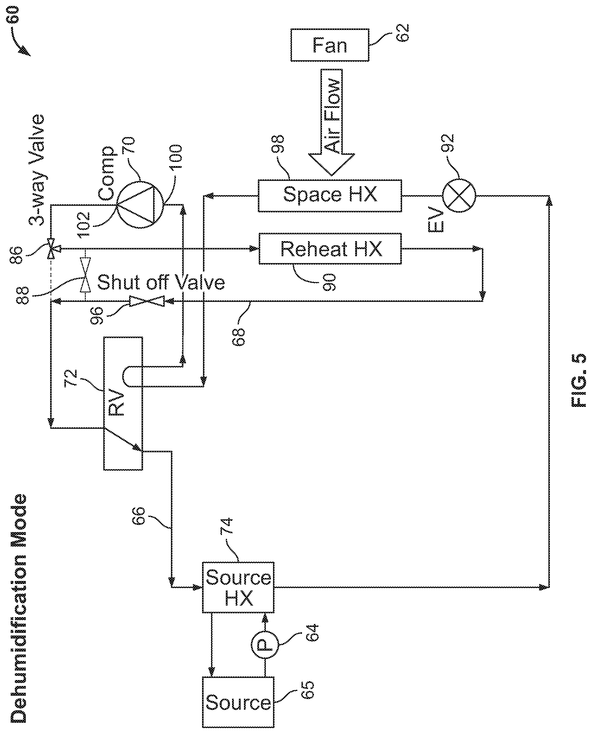
FIG. 5 is a schematic showing the embodiment of FIG. 4 in a dehumidification mode.
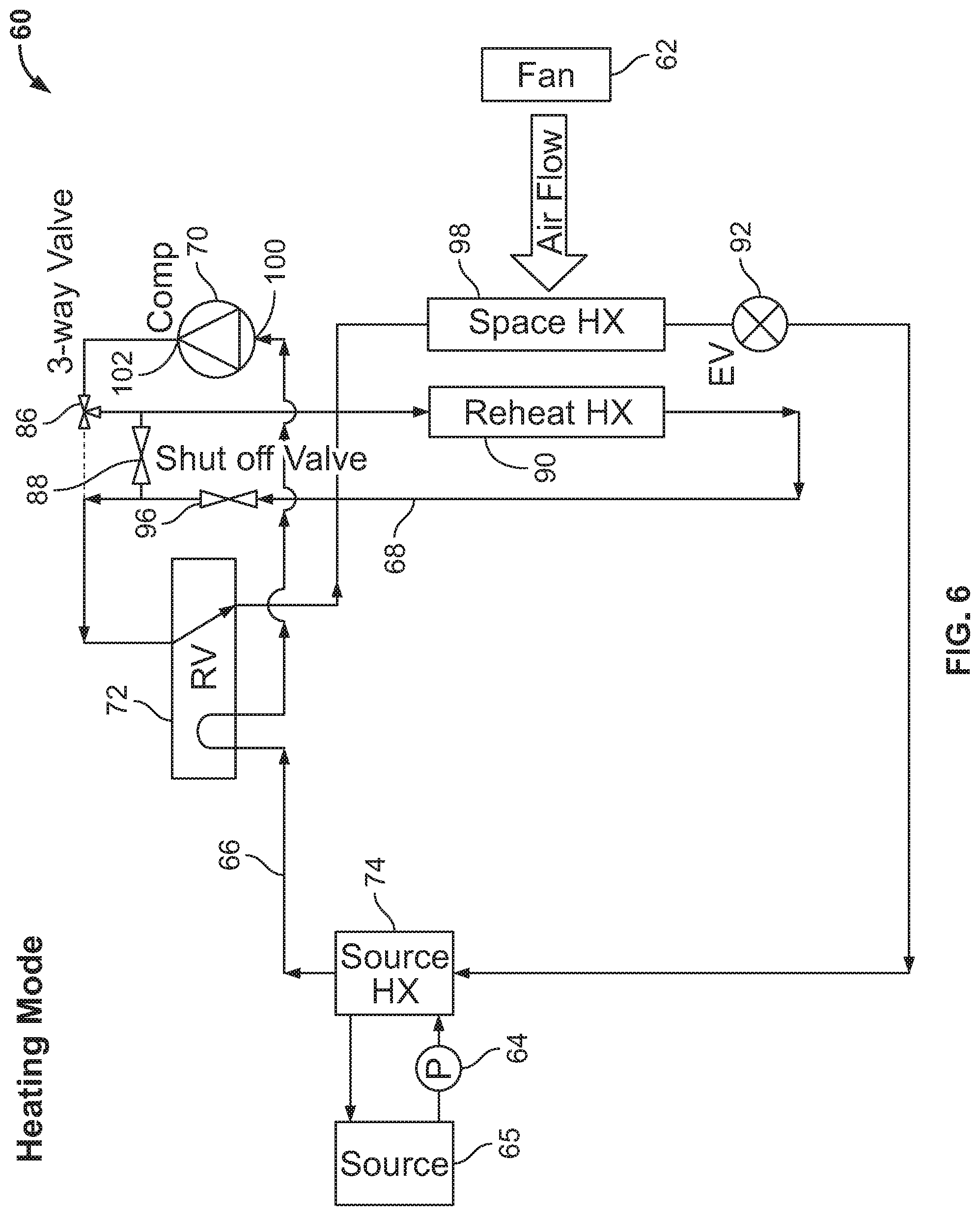
FIG. 6 is a schematic showing the embodiment of FIG. 4 in a heating mode.
FIG. 7 is a schematic showing another embodiment of a heat pump system of the instant disclosure in a cooling mode.
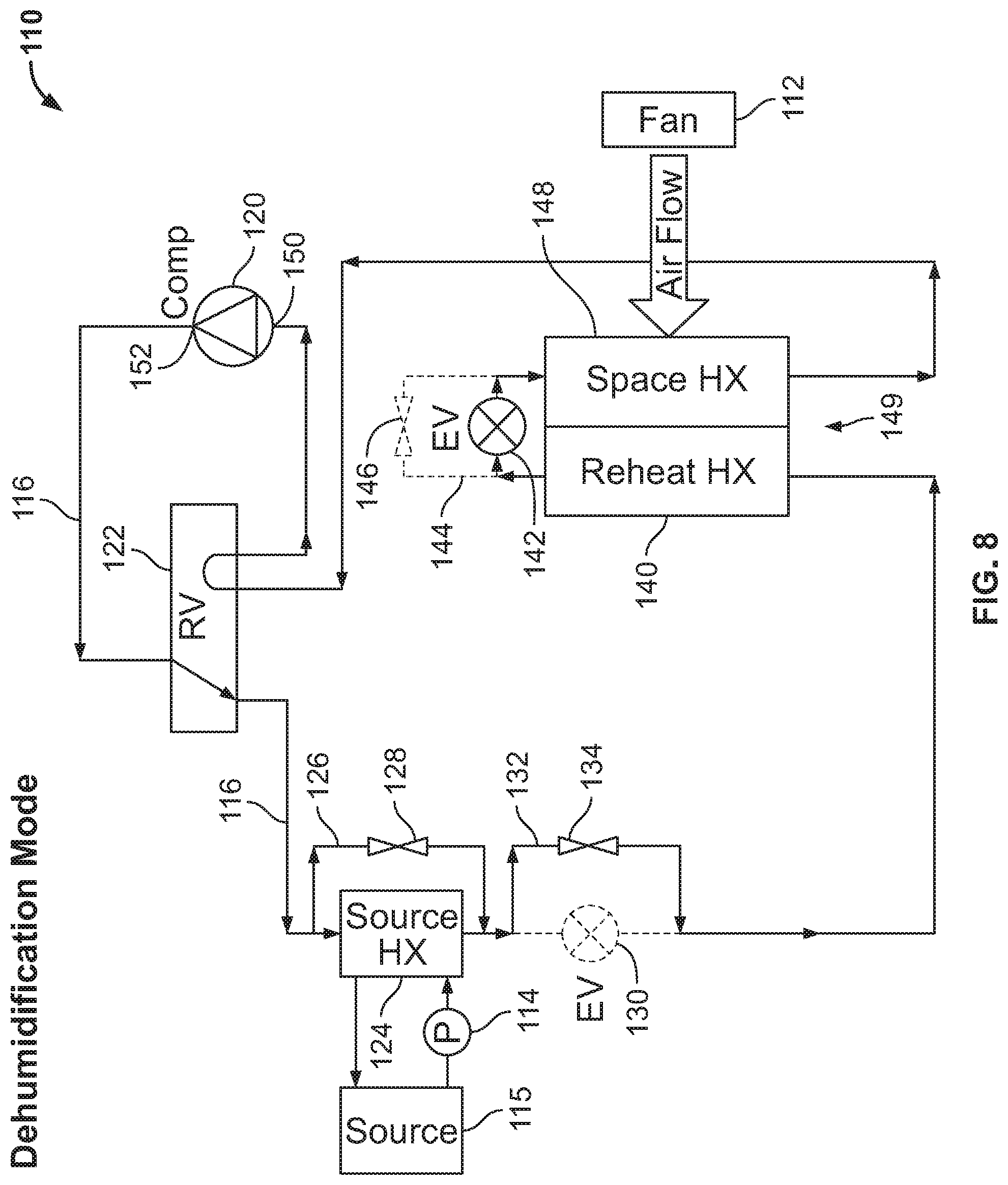
FIG. 8 is a schematic showing the embodiment of FIG. 7 in a dehumidification mode.
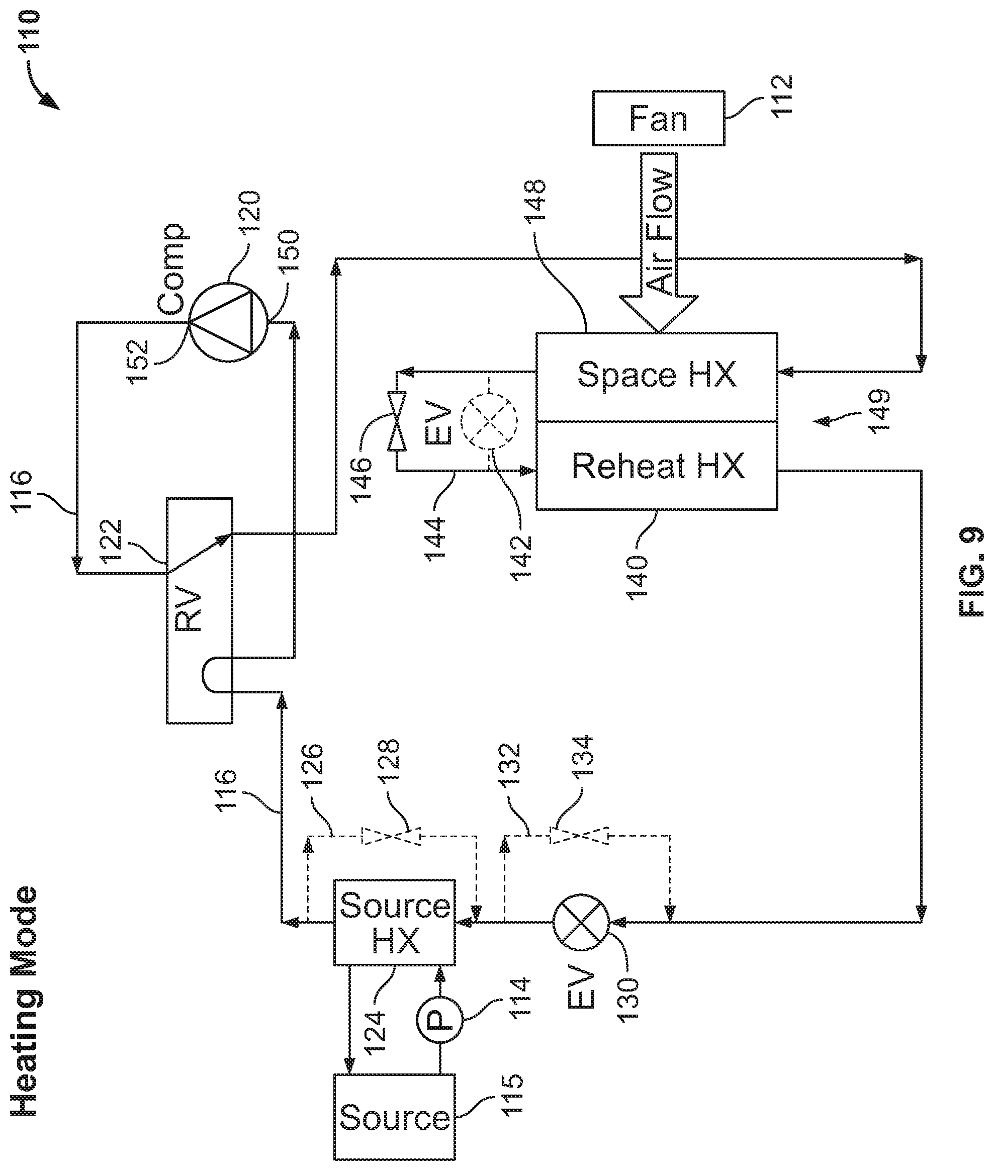
FIG. 9 is a schematic showing the embodiment of FIG. 7 in a heating mode.
FIG. 10 is a schematic showing a controller and exemplary heat pump components that may be controlled by the controller.
DETAILED DESCRIPTION
Although the figures and the instant disclosure describe one or more embodiments of a heat pump system, one of ordinary skill in the art would appreciate that the teachings of the instant disclosure would not be limited to these embodiments. It should be appreciated that any of the features of an embodiment discussed with reference to the figures herein may be combined with or substituted for features discussed in connection with other embodiments in this disclosure.
The instant disclosure provides improved and flexible heat pump operation when dehumidification of a conditioned space is required. In one embodiment of a vapor compression circuit, a reheat heat exchanger is positioned upstream of a 3-way valve with respect to the refrigerant flow. In another embodiment, a reheat heat exchanger is positioned downstream of the 3-way valve but upstream of a source heat exchanger with respect to the refrigerant flow. In yet another embodiment, a reheat heat exchanger is positioned downstream of a source heat exchanger with respect to the refrigerant flow.
All three of the foregoing embodiments provide operational flexibility via a modulating, pulse width modulating (PWM) or rapid cycle solenoid valve diverting at least a portion of the refrigerant around the reheat heat exchanger in the dehumidification mode of operation. Alternatively or additionally, an ON-OFF 3-way valve and a bypass valve may be replaced by the modulating, PWM or rapid cycle solenoid 3-way valve. A controller comprising a processor coupled to memory on which one or more software algorithms are stored may process and issue commands to open, partially open, or close any of the valves disclosed herein. Open or closed feedback loops may be employed to determine current and desired valve positions.
All three of the embodiments may employ variable speed or multi-speed refrigerant and/or source fluid pumps, fan and/or blower motor, and compressor to control dehumidification capability and head pressure. The controller may be configured to operate any or all of these devices to provide the desired system performance. In the heating mode, the reheat heat exchanger may act as an auxiliary condenser or evaporator to enhance system performance and avoid the "cold blow" effect. Any of the expansion valves disclosed herein may be any type of expansion device, including a thermostatic expansion valve, and can be electronic, mechanical, electromechanical, or fixed orifice type. The charge migration or condensation of refrigerant in the reheat heat exchanger can be controlled by a charge compensator or a shutoff valve. The potential oil accumulation in the reheat heat exchanger when the reheat refrigeration circuit is inactive can be controlled by periodically activating the reheat circuit for a short period of time. In at least one of the embodiments described herein, a portion of the existing space heat exchanger may act as a reheat heat exchanger during the dehumidification mode of operation. All of the embodiments described herein provide improved comfort level, system performance, and system reliability.
Turning now to the drawings and to FIGS. 1-9 in particular, there are shown various embodiments of a heat pump system configured to provide dehumidification of a conditioned space when required. For example, FIGS. 1-3 show heat pump system 10 configured in a cooling mode, a dehumidification mode, and a heating mode, respectively. FIGS. 4-6 show heat pump system 60 configured in a cooling mode, a dehumidification mode, and a heating mode, respectively. FIGS. 7-9 show heat pump system 110 configured in a cooling mode, a dehumidification mode, and a heating mode, respectively. Systems 10, 60, 110 are designed for conditioning the air in a predetermined space. As used herein, "air conditioning" and related terms related to heating, cooling, or dehumidifying the air, and to any combination of these.
In the embodiment of FIGS. 1-3, heat pump system 10 includes a heat pump loop 16 comprising a reheat circuit 18. Heat pump system 10 includes compressor 20; reversing valve 22; source heat exchanger 24; source heat exchanger bypass circuit 26 comprising bypass valve 28; expansion valve 30; expansion valve bypass circuit 32 comprising check valve 34; three-way valve 36; reheat circuit 18 comprising reheat bypass valve 38 and reheat heat exchanger 40; expansion valve 42; expansion valve bypass circuit 44 comprising check valve 46; and space heat exchanger 48. Compressor 20 includes a suction inlet port 50 and a discharge outlet port 52. The heat pump system 10 may include a fan 12 associated with the space heat exchanger 48 and the fan 12 may be a variable airflow fan.
Referring to FIG. 1, heat pump system 10 is shown in a cooling mode with reheat circuit 18 inactive. Compressed gaseous refrigerant exiting the compressor 20 at discharge outlet port 52 is conveyed to the reversing valve 22 where the refrigerant is then conveyed to the source heat exchanger 24 acting as a condenser. In cooling mode, bypass valve 28 is closed, which causes source heat exchanger bypass circuit 26 to be inactive. The capacity (e.g. speed) of the liquid pump 14 circulating the fluid through heat exchanger 24 may be adjusted to control heat rejected by the heat exchanger 24 and system discharge pressure. Likewise, with expansion valve 30 being closed, and with the orientation of check valve 34 permitting flow therethrough, the expansion valve bypass circuit 32 is configured to be active. Thus, all of the refrigerant from the compressor discharge conduit passes through the source heat exchanger 24 and the expansion valve bypass circuit 32, after which the refrigerant is conveyed to three-way valve 36.
Three-way valve 36 is configured to direct the refrigerant to expansion valve 42 rather than entering the reheat circuit 18. Wth expansion valve bypass circuit 44 inactive due to the opposite flow orientation of check valve 46, the refrigerant is directed to the expansion valve 42 where the refrigerant is metered, expanded and cooled before entering the space heat exchanger 48. Refrigerant conveyed in the coil of the space heat exchanger 48, which acts as an evaporator when system 10 is in cooling mode, absorbs heat from air flowing over the coil of the space heat exchanger 48 thereby cooling the air for conditioning a space. Refrigerant exiting the space heat exchanger 48 is then conveyed to the reversing valve 22, which directs the refrigerant back to the compressor 20 to start the cycle over again. It should be noted that the coil in the reheat heat exchanger 40 may be filled with subcooled liquid refrigerant.
Referring to FIG. 2, system 10 is shown configured in a dehumidification mode. In this mode, the flow of refrigerant through heat pump loop 16 is the same as shown in FIG. 1 except the source heat exchanger bypass circuit 26 may be active (i.e., bypass valve 28 may be fully opened, partially opened, or fully closed to obtain optimum refrigerant conditions at the inlet of the reheat heat exchanger 40), the expansion valve bypass circuit 32 is active (i.e., expansion valve 30 is closed), and the expansion valve bypass circuit 44 is inactive (due to the opposite flow orientation of check valve 46). In addition, rather than three-way valve 36 directing refrigerant to expansion valve 42, three-way valve 36 instead directs the refrigerant to reheat heat exchanger 40, which is positioned downstream of the space heat exchanger 48 relative to air flowing over the respective coils. Thus, air flowing over the coil of the space heat exchanger 48 is cooled and dehumidified by the space heat exchanger 48 and then the air is directed to flow over the reheat heat exchanger 40 to add heat to the air to avoid overcooling the air. Bypass valve 28 may be automatically controlled to be fully opened, partially opened, or fully closed as needed to control the refrigerant inlet condition(s) to reheat heat exchanger 40. Bypass valve 28 may be automatically cycled open and closed and/or controlled on and off with a PWM signal to modulate the amount of refrigerant flowing through the source heat exchanger 24. The capacity (e.g. speed) of the liquid pump 14 circulating the fluid through heat exchanger 24 may be adjusted to control heat rejected by the heat exchanger 24 and system discharge pressure.
If the three-way valve 36 is configured to be adjustable, the three-way valve 36 may control the refrigerant mass flow rate flowing through reheat circuit 18 to provide adjustable outlet air temperature exiting from the coils of the space heat exchanger 48 and reheat heat exchanger 40 for distribution to the air-conditioned space. If the three-way valve 36 is not adjustable, reheat bypass valve 38 may be configured to cause some of the refrigerant flow to bypass the reheat heat exchanger 40 to reduce the mass flow rate entering the reheat heat exchanger 40. The reheat bypass valve 38 may be automatically cycled opened and closed and/or controlled on and off with a PWM signal to modulate the amount of refrigerant flowing through the reheat heat exchanger 40.
Referring to FIG. 3, system 10 is shown configured in a heating mode with added capacity for heating the conditioned air using the reheat heat exchanger 40. In this mode, hot gaseous refrigerant exiting the compressor 20 at discharge outlet port 52 is directed to reversing valve 22, which directs the refrigerant to the space heat exchanger 48. Space heat exchanger 48 acts as a condenser when system 10 is in heating mode. Wth a closed expansion valve 42, refrigerant exiting the space heat exchanger 48 is directed to the active expansion valve bypass circuit 44 and through check valve 46. The refrigerant is then conveyed to the reheat heat exchanger 40. To heat a space, air flowing over space heat exchanger 48 picks up heat from the space heat exchanger 48 before the air is directed to flow over the reheat heat exchanger 40 to pick up additional heat. Reheat heat exchanger 40 therefore acts as an auxiliary condenser in this heating mode.
Refrigerant exiting the reheat heat exchanger is then directed to three-way valve 36, which directs the flow to expansion valve 30 while expansion valve bypass circuit 32 is inactive. The expansion valve 30 expands the refrigerant thereby cooling the refrigerant before entering the source heat exchanger 24 while source heat exchanger bypass circuit 26 is inactive (i.e., bypass valve 28 is closed). The source heat exchanger 24 acts as an evaporator to fully evaporate the refrigerant before the refrigerant is directed to the reversing valve 22, which directs the refrigerant to the suction inlet port 50 of the compressor 20 to continue the cycle. With the reheat heat exchanger 40 acting as an auxiliary condenser, system 10 may improve the subcooling and consequently the capacity and efficiency of system 10 while in this heating mode, as well as increase supply air temperature preventing the "cold blow" effect. In cold climates, reheat heat exchanger 40 provides additional heating capacity to avoid auxiliary (e.g. electric) heaters.
Referring to FIGS. 4-6, there is shown another embodiment of a heat pump system configured in a cooling mode, a dehumidification mode, and a heating mode, respectively. Heat pump system 60 includes heat pump loop 66 comprising reheat circuit 68. Heat pump loop 66 includes compressor 70, reversing valve 72, source heat exchanger 74, expansion valve 92, space heat exchanger 98, and three-way valve 86. Reheat circuit 68 of heat pump loop 66 includes reheat heat exchanger 90, reheat bypass valve 88, and shutoff valve 96. Compressor 70 includes suction inlet port 100 and discharge outlet port 102. Three-way valve 86 is positioned downstream of the compressor discharge outlet port 102 of compressor 70 and upstream of reversing valve 72. The heat pump system 60 may include a fan 62 associated with the space heat exchanger 98 and the fan 62 may be a variable airflow fan.
Unlike heat pump system 10, heat pump system 60 does not require expansion valve bypass circuits. And although the reheat heat exchanger is positioned downstream of the space heat exchanger in terms of the direction of air flowing over the coils of these two heat exchangers, the refrigerant connection conduits for the reheat circuit 68 connect with the heat pump loop 66 downstream of the compressor 70 and upstream of the reversing valve 72. Similarly to the previous embodiment, the bypass around source heat exchanger 74 may be applied, but not shown for simplicity.
Referring FIG. 4, heat pump system 60 is shown configured in a cooling mode with the reheat circuit 68 inactive. Hot gaseous refrigerant exiting the discharge outlet port 102 of compressor 70 is directed by a conduit to the three-way valve 86, which directs the gas to reversing valve 72, which in turn directs the gas to source heat exchanger 74. Refrigerant exiting source heat exchanger 74 acting as a condenser is directed to expansion valve 92. Refrigerant exiting the expansion valve 92 is directed to space heat exchanger 98. Refrigerant exiting space heat exchanger 98 acting as an evaporator is directed to the reversing valve 72, which in turn directs the gas back to the suction inlet port 100 of compressor 70. Shutoff valve 96 in combination with proper control of three-way valve 86 insures that hot gas from the compressor 70 does not enter reheat circuit 68 when heat pump system 10 is operating in cooling mode. Refrigerant conveyed in the coil of the space heat exchanger 98 absorbs heat from air flowing over the space heat exchanger 98 thereby cooling the air for conditioning a space.
Referring to FIG. 5, heat pump system 60 is shown configured in a dehumidification mode. In this mode, reheat circuit 68 is active. Hot gaseous refrigerant exiting compressor 70 at discharge outlet port 102 is directed to three-way valve 86, which in turn directs the refrigerant to reheat heat exchanger 90 positioned downstream of space heat exchanger 98 such that air cooled after flowing across the space heat exchanger 98 is then caused to flow over the reheat heat exchanger 90 to pick up an heat, thereby preventing overcooling the air distributed to the air-conditioned space.
Refrigerant exiting reheat heat exchanger 90 is directed to open shutoff valve 96. The refrigerant is then directed to reversing valve 72, which directs the refrigerant to source heat exchanger 74 to exchange heat with the source fluid. The refrigerant is then conveyed to the expansion valve 92, which expands and therefore causes the pressure and temperature reduction of the refrigerant, before refrigerant enters space heat exchanger 98. Refrigerant exiting the space heat exchanger 98 acting as an evaporator is then directed to the reversing valve 72, which in turn directs the refrigerant back to the suction inlet port 100 of compressor 70. Thus, air flowing over the space heat exchanger 98 is cooled by the space heat exchanger 98 and then the air is directed to flow over the reheat heat exchanger 98 to add heat to the air to prevent overcooling the air.
The three-way valve 86 may be adjustable as described above to adjust the refrigerant mass flow rate provided to the reheat circuit 68 for optimum supply air temperature that is distributed to the air-conditioned space. Alternatively, as described above, the three-way valve may not be adjustable. In that case, reheat bypass valve 88 may be configured as a simple on-off valve. As described above, reheat bypass valve 88, may be controlled via a PWM algorithm that controls the mass flow rate of refrigerant entering reheat heat exchanger 90 by cycling reheat bypass valve 88 open and closed according to the algorithm. The capacity (e.g. speed) of the liquid pump 64 circulating the fluid through heat exchanger 74 may be adjusted to control heat rejected by the heat exchanger 74 and system discharge pressure.
Referring to FIG. 6, heat pump system 60 is shown configured in a heating mode. In this mode, reheat circuit 68 is active (i.e., reheat bypass valve 88 is closed) and the reheat heat exchanger 90 acts as an additional condenser to supplement the air heating capacity of space heat exchanger 98 to heat air flowing across the space heat exchanger 98 and reheat heat exchanger 90.
In this mode, hot gaseous refrigerant exiting the discharge outlet port 102 of compressor 70 is directed to three-way valve 86, which in turn directs the refrigerant to reheat heat exchanger 90. The refrigerant is then directed to open shutoff valve 96, after which the refrigerant is directed to reversing valve 72. The refrigerant is then conveyed to space heat exchanger 98, after which the refrigerant is conveyed to the expansion valve 92. The expanded refrigerant of reduced pressure and temperature after passing through the expansion valve 92 is then conveyed to the source heat exchanger 74, which acts as an evaporator. The refrigerant discharged from the source heat exchanger 74 is conveyed to the reversing valve 72, which directs the refrigerant back to the suction inlet port 100 of compressor 70.
To heat a space, air flowing over the space heat exchanger 98 picks up heat from the space heat exchanger 98 before the air is directed to flow over the reheat heat exchanger 90 to pick up additional heat. Reheat heat exchanger 90 therefore acts as an auxiliary condenser in this heating mode. The extra condenser provided by reheat heat exchanger 90 helps to increase the heat transfer to the air, increase the subcooling of the refrigerant, and increase the capacity and efficiency of heat pump system 60, as well as increase temperature of the air supplied to a conditioned space therefore avoiding a "cold blow" effect. The capacity (e.g. speed) of the liquid pump 64 circulating the fluid through heat exchanger 74 may be adjusted to control heat rejected by the heat exchanger 74 and system discharge pressure.
FIG. 7-9 shows another embodiment of a heat pump system. As shown in the figures, heat pump system 110 includes compressor 120 comprising suction inlet port 150 and discharge outlet port 152, reversing valve 122, source heat exchanger 124, source heat exchanger bypass circuit 126 comprising bypass valve 128, expansion valve 130, expansion valve bypass circuit 132 comprising bypass valve 134, reheat heat exchanger 140, expansion valve 142, expansion valve bypass circuit 144 comprising bypass valve 146, and space heat exchanger 148. The heat pump system 110 may include a fan 112 associated with the space heat exchanger 148 and the fan 112 may be a variable airflow fan.
Heat pump system 110 is schematically similar to heat pump system 10, but instead of employing two different air coils, a larger space coil is employed. In this embodiment, expansion valve bypass circuit 144 and expansion valve 142 of heat pump system 110 are positioned between reheat heat exchanger 140 and space heat exchanger 148 and therefore divide the larger space coil into two parts. One part may be used as a reheat coil and the other part may be used as a main space heating/cooling coil.
Referring to FIG. 7, heat pump system 110 is shown in a cooling mode. Hot gaseous refrigerant exiting the discharge outlet port 152 of compressor 120 is directed by a conduit to the reversing valve 122, which in turn directs the refrigerant gas to source heat exchanger 124. Refrigerant exiting source heat exchanger 124 acting as a condenser is directed to expansion valve 130, which is configured to meter, expand and cool the refrigerant before the refrigerant enters reheat heat exchanger 140, which is the first stage of the two-stage space heat exchanger 149. Upon exiting the reheat heat exchanger 140 acting as an evaporator, the refrigerant bypasses a closed expansion valve 142. The refrigerant instead is conveyed through expansion valve bypass circuit 144 and bypass valve 146 to then flow through the space heat exchanger 148, which is the second stage of the two-stage space heat exchanger 149. In cooling mode, space heat exchanger 148 acts as an extension of the evaporator provided by reheat heat exchanger 140 to increase the size of the evaporator. Thus, refrigerant conveyed in the space heat exchanger 148 and the reheat heat exchanger 140 absorbs heat from air flowing over these coils to cool the air for conditioning a space.
For control purposes, bypass valve 146 may be automatically cycled open and closed and/or controlled on and off with a PWM signal. Refrigerant exiting the space heat exchanger 148 is conveyed to reversing valve 122, which directs the refrigerant to suction inlet port 150 of compressor 120.
Referring to FIG. 8, heat pump system 110 is shown in a dehumidification mode. In this mode, hot gaseous refrigerant exiting the discharge outlet port 152 of compressor 120 is directed to the reversing valve 122, which in turn directs the refrigerant to source heat exchanger 124 acting as a condenser. As shown in the figure, source heat exchanger bypass circuit 126 is active via bypass valve 128, and the expansion valve bypass circuit 132 is active via bypass valve 134. Consequently, some, none, or all of the heated refrigerant may be permitted to flow through the source heat exchanger 124, and some, none, or all of the refrigerant may be permitted to flow through the source heat exchanger bypass circuit 126 to obtain optimum refrigerant conditions at the inlet of reheat heat exchanger 140. Bypass valve 128 controls the amount of refrigerant mass flow that traverses through the source heat exchanger bypass circuit 126, which affects the amount of refrigerant mass flow traversing through the source heat exchanger 124. Bypass valve 128 may be automatically cycled open and closed and/or controlled on and off with a PWM signal to modulate the amount of refrigerant flowing through the source heat exchanger bypass circuit 126. The capacity (e.g. speed) of the liquid pump 114 circulating the fluid through heat exchanger 124 may be adjusted to control heat rejected by the heat exchanger 124 and system discharge pressure.
Refrigerant exiting the source heat exchanger 124 acting as a condenser and source heat exchanger bypass circuit 126 are combined and then directed to expansion valve bypass circuit 132. In dehumidification mode, none of the refrigerant enters the expansion valve 130.
Refrigerant exiting the expansion bypass circuit 132 is directed to reheat heat exchanger 140. Upon exiting reheat heat exchanger 140 and with bypass valve 146 being closed, subcooled refrigerant is directed to expansion valve 142, which meters, expands and cools the refrigerant before the refrigerant enters space heat exchanger 148 acting as an evaporator. Upon leaving space heat exchanger 148, the refrigerant is directed to the reversing valve 122, which then directs the flow back to the suction inlet port 150 of compressor 120. Thus, air flowing over the space heat exchanger 148 is cooled by the space heat exchanger 148 and then the air is directed to flow over the reheat heat exchanger 140 to add heat to prevent overcooling the air.
Referring to FIG. 9, heat pump system 110 is configured in a heating mode. For example, hot gaseous refrigerant leaving the discharge outlet port 152 of compressor 120 is directed to reversing valve 122, which directs the refrigerant to space heat exchanger 148 acting as a condenser. Refrigerant exiting space heat exchanger 148 is directed to bypass valve 146, which in turn directs the refrigerant to reheat heat exchanger 140. The expansion valve 142 is not needed for heating mode. To heat a space, air flowing over the coil of space heat exchanger 148 picks up heat from the space heat exchanger 148 before the air is directed to flow over the reheat heat exchanger 140 to pick up additional heat. Reheat heat exchanger 140 therefore acts as an auxiliary condenser in this heating mode.
Refrigerant leaving reheat heat exchanger 140 is directed to expansion valve 130. Expansion valve bypass circuit 132 and source heat exchanger bypass circuit 126 are not active (i.e., bypass valves 128, 134 are closed) when heat pump system 110 is configured in the heating mode. Refrigerant leaving the expansion valve 130 is directed to source heat exchanger 124 acting as an evaporator to exchange heat with the source fluid. Refrigerant leaving source heat exchanger 124 is then directed the reversing valve 122, which directs the refrigerant back to the suction inlet port 150 of compressor 120. The extra condenser provided by reheat heat exchanger 140 helps to increase the heat transfer to the air, increase the subcooling of the refrigerant, and increase the capacity and efficiency of heat pump system 110, as well as increase temperature of the air supplied to a conditioned space therefore avoiding a "cold blow" effect. The capacity (e.g. speed) of the liquid pump 114 circulating the fluid through heat exchanger 124 may be adjusted to control heat rejected by the heat exchanger 124 and system discharge pressure.
Heat pump loops 16, 66, 116 include a conduit through which refrigerant flows and which fluidly connects the components of heat pump systems 10, 60, 110 to one another. Compressors 20, 70, 120 may each be a variable capacity compressor, such as a variable speed compressor, a compressor with an integral pulse-width modulation option, or a compressor incorporating various unloading options. These types of compressors allow for better control of the operating conditions and management of the thermal load on the heat pump loops 16, 66, 116.
Reversing valves 22, 72, 122 are positioned along the conduit on the discharge side of compressors 20, 70, 120 and are configured to selectively operate the heat pump loops 16, 66, 116 in a cooling mode, a dehumidification mode, and a heating mode by controlling the direction of refrigerant flowing in the heat pump loops 16, 66, 116.
Source heat exchangers 24, 74, 124 may each be a refrigerant-to-water, refrigerant-to-brine, or refrigerant-to-air heat exchanger and is not limited to any particular heat exchanger type or configuration. Source heat exchangers 24, 74, 124 are fluidly connected to a source 15, 65, 115, and the fluid, usually but not necessarily water, is circulated by pumps 14, 64, 114. Pumps 14, 64, 114 may be a variable capacity pump (e.g. a variable speed pump, a pump controlled by PWM signal, a cycling ON/OFF pump, a pump with a bypass circuit or other means of unloading) for a more efficient operation and better system control. Similarly, space heat exchangers 48, 98, 148 are not limited to any particular heat exchanger type or configuration.
Expansion valves 30, 42, 92, 130, 142 may each be an electronic expansion valve, a mechanical expansion valve, a fixed-orifice/capillary tube/accurator, or any combination of the these. These valves may have bi-directional functionality or may be replaced by a pair of uni-directional expansion devices coupled with the associated bypass check valves to provide refrigerant rerouting when the flow changes direction throughout the refrigerant cycle between cooling and heating modes of operation.
Valves 28, 38, 88, 96, 128, 146 may each be electronically controllable, mechanically and/or electromechanically actuated valves, and may have bi-directional flow functionality.
Referring to FIG. 10, heat pump systems 10, 60, 110 may include controller 78 comprising processor 80 and memory 82 on which one or more software programs are stored. The controller 78 may be configured to control operation of the check valves 34, 46, the shut off valve 96, the reversing valves 22, 72, 122, the bypass valves 28, 38, 88, 128, 134, 146, the 3-way valves 36, 86, the first and second expansion devices 30, 42, 92, 130, 142, the compressors 20, 70, 120, the liquid pumps 14, 64, 114 for circulating water or brine solution through the source heat exchangers 24, 74, 124, the fans 12, 62, 112 for flowing air over the space heat exchangers 48, 98, 148, and the reheat heat exchangers 40, 90, 140.
While specific embodiments have been described in detail, it will be appreciated by those skilled in the art that various modifications and alternatives to those details could be developed in light of the overall teachings of the disclosure. Accordingly, the disclosure herein is meant to be illustrative only and not limiting as to its scope and should be given the full breadth of the appended claims and any equivalents thereof.
* * * * *
References
D00000
D00001
D00002
D00003
D00004
D00005
D00006
D00007
D00008
D00009
D00010
XML
uspto.report is an independent third-party trademark research tool that is not affiliated, endorsed, or sponsored by the United States Patent and Trademark Office (USPTO) or any other governmental organization. The information provided by uspto.report is based on publicly available data at the time of writing and is intended for informational purposes only.
While we strive to provide accurate and up-to-date information, we do not guarantee the accuracy, completeness, reliability, or suitability of the information displayed on this site. The use of this site is at your own risk. Any reliance you place on such information is therefore strictly at your own risk.
All official trademark data, including owner information, should be verified by visiting the official USPTO website at www.uspto.gov. This site is not intended to replace professional legal advice and should not be used as a substitute for consulting with a legal professional who is knowledgeable about trademark law.