Patient-specific humeral guide designs
Kehres , et al. February 23, 2
U.S. patent number 10,925,622 [Application Number 16/257,967] was granted by the patent office on 2021-02-23 for patient-specific humeral guide designs. This patent grant is currently assigned to Biomet Manufacturing, LLC. The grantee listed for this patent is Biomet Manufacturing, LLC. Invention is credited to Jason M. Hurst, Benjamin Isaiah Joseph, Clinton E. Kehres, Nathan A. Winslow.


View All Diagrams
| United States Patent | 10,925,622 |
| Kehres , et al. | February 23, 2021 |
Patient-specific humeral guide designs
Abstract
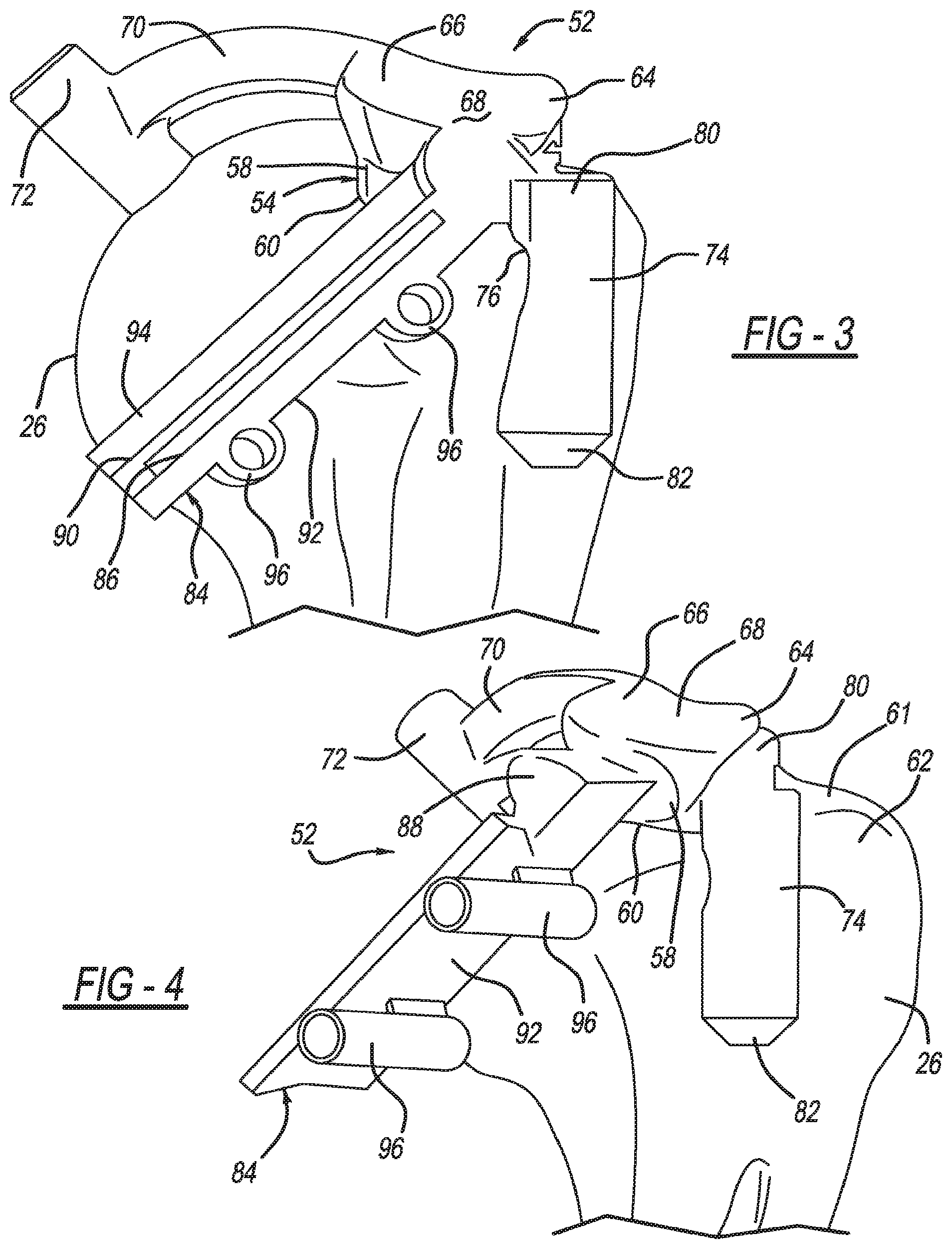
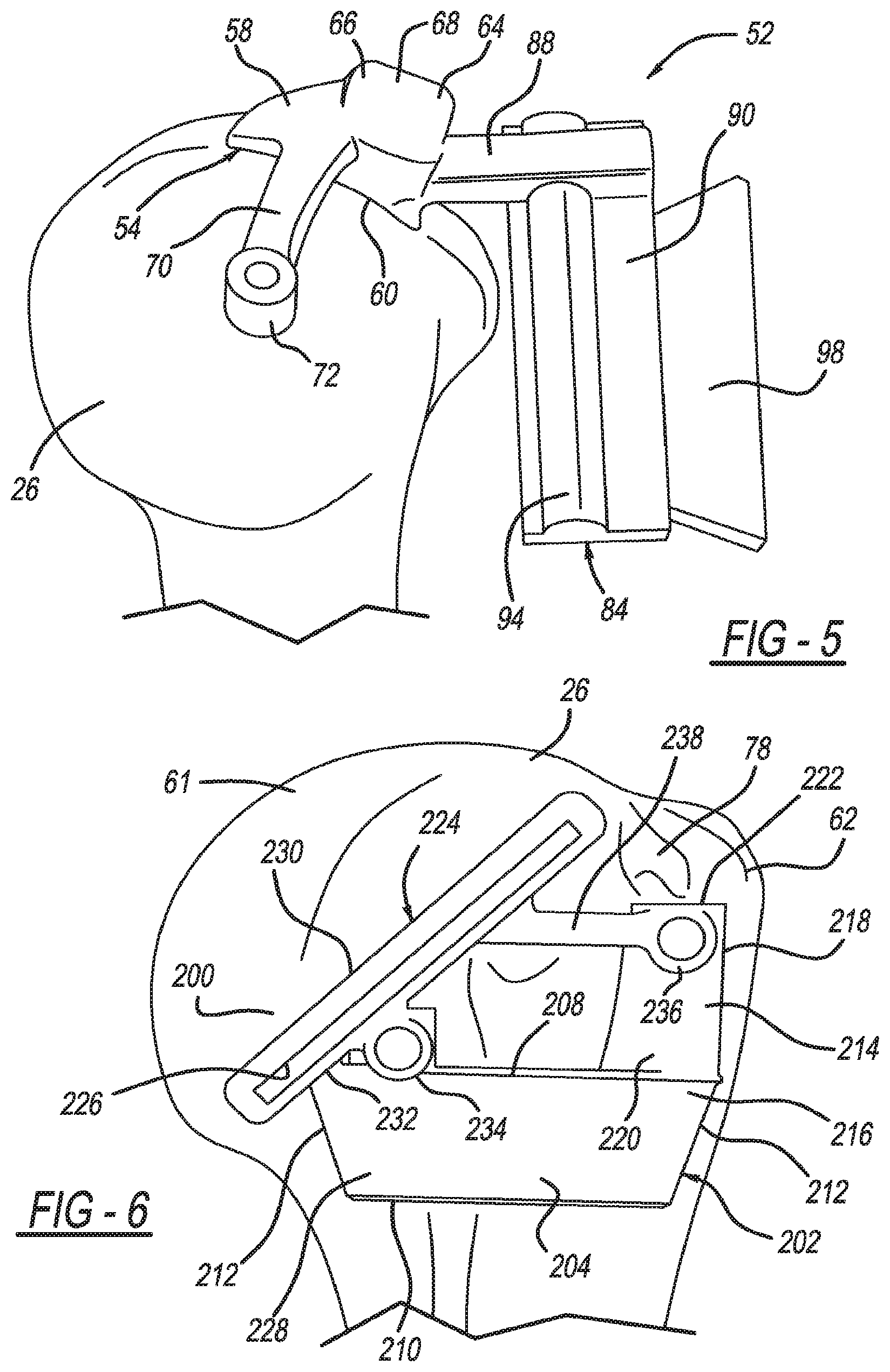
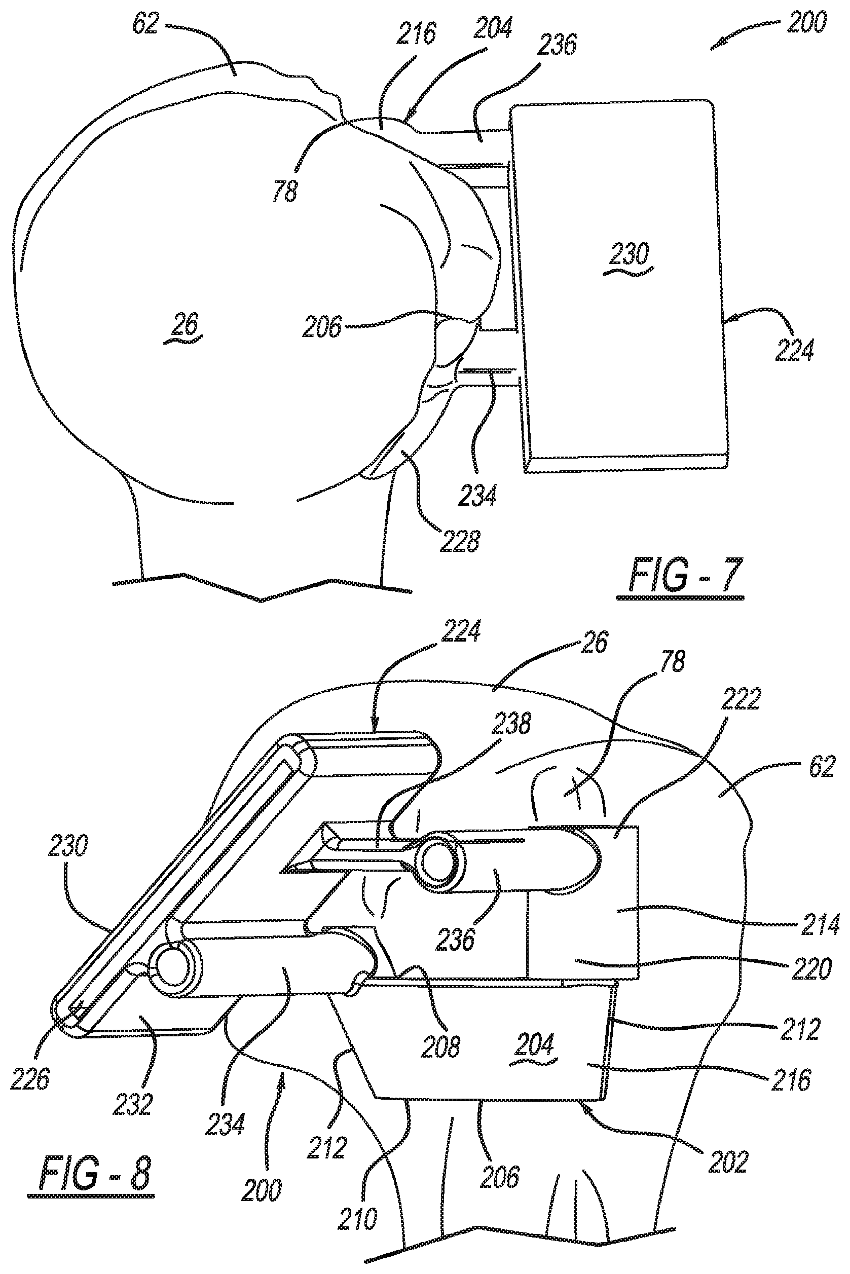
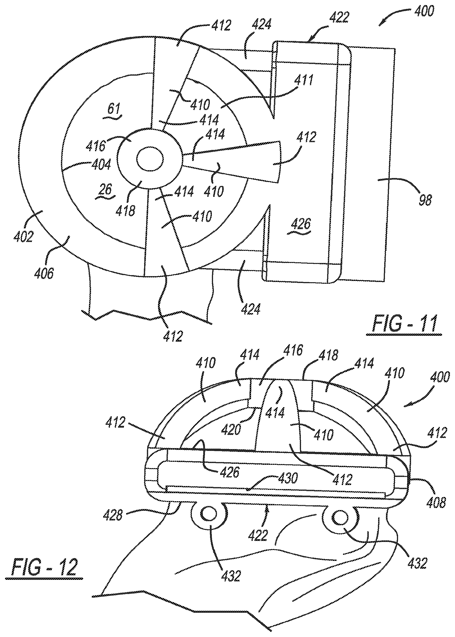
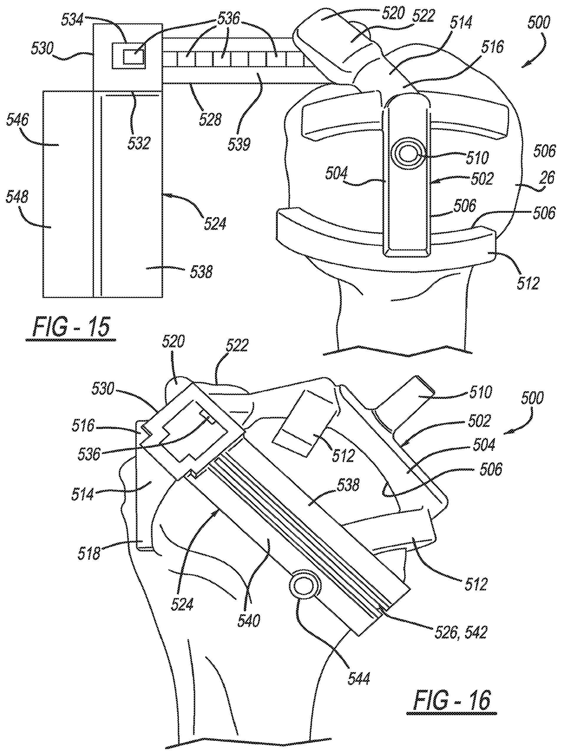
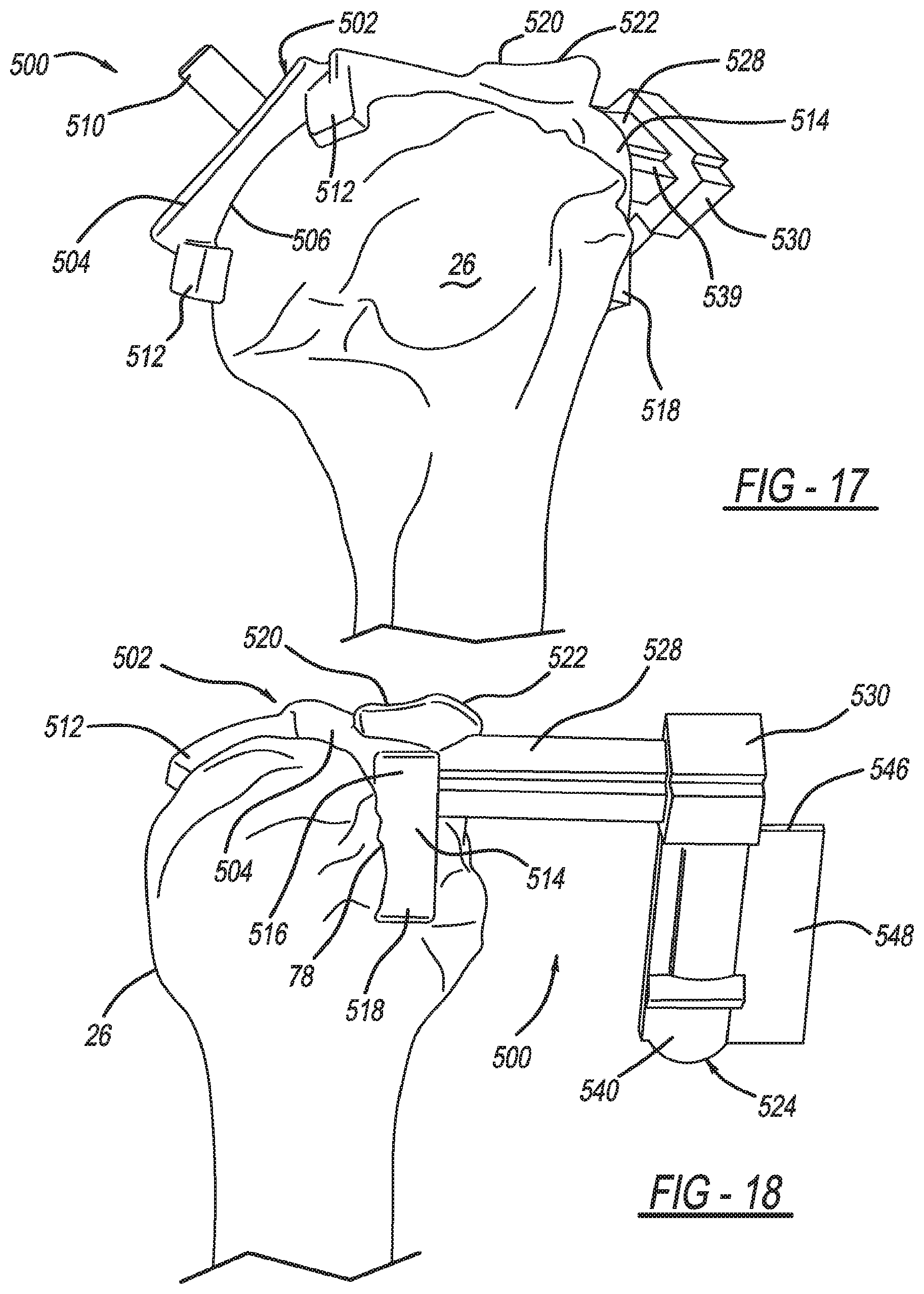
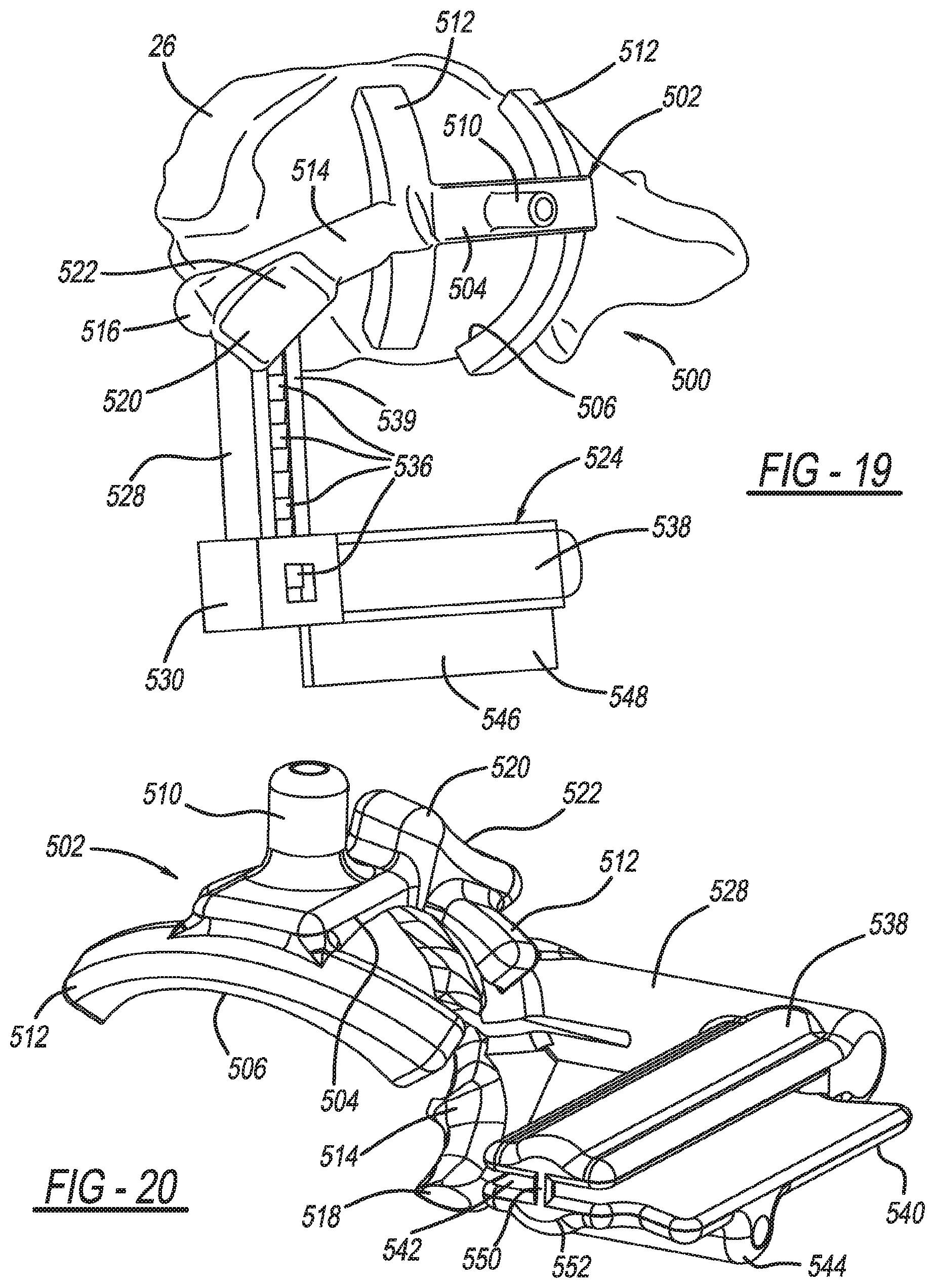
A humeral cut guide member for resectioning or resurfacing a humeral head, including a bone-engagement member including a first patient-specific bone-engagement surface that is complementary and made to substantially mate and nest in only one position on a specific patient's humeral head; a registration member connected to the bone-engagement member including a second patient-specific bone engagement surface that is sized and made to substantially mate and nest in only one position with the specific patient's bicipital groove; and a cut guide plate connected to the bone-engagement member and defining an elongated slot.
| Inventors: | Kehres; Clinton E. (Warsaw, IN), Joseph; Benjamin Isaiah (Ft. Wayne, IN), Winslow; Nathan A. (Warsaw, IN), Hurst; Jason M. (New Albany, OH) | ||||||||||
|---|---|---|---|---|---|---|---|---|---|---|---|
| Applicant: |
|
||||||||||
| Assignee: | Biomet Manufacturing, LLC
(Warsaw, IN) |
||||||||||
| Family ID: | 1000005374906 | ||||||||||
| Appl. No.: | 16/257,967 | ||||||||||
| Filed: | January 25, 2019 |
Prior Publication Data
| Document Identifier | Publication Date | |
|---|---|---|
| US 20190150958 A1 | May 23, 2019 | |
Related U.S. Patent Documents
| Application Number | Filing Date | Patent Number | Issue Date | ||
|---|---|---|---|---|---|
| 14750325 | Jun 25, 2015 | 10226262 | |||
| Current U.S. Class: | 1/1 |
| Current CPC Class: | A61B 17/1778 (20161101); A61B 17/15 (20130101); A61B 2034/108 (20160201) |
| Current International Class: | A61B 17/15 (20060101); A61B 17/17 (20060101); A61B 34/10 (20160101) |
References Cited [Referenced By]
U.S. Patent Documents
| 1480285 | January 1924 | Moore |
| 2181746 | November 1939 | Siebrandt |
| 2407845 | September 1946 | Orisan |
| 2416228 | February 1947 | Sheppard |
| 2618913 | November 1952 | Plancon |
| 2910978 | November 1959 | Urist |
| 3330611 | July 1967 | Heifetz |
| 3840904 | October 1974 | Tronzo |
| 3975858 | August 1976 | Much |
| 4246895 | January 1981 | Rehder |
| 4306866 | December 1981 | Weissman |
| 4324006 | April 1982 | Charnley |
| 4421112 | December 1983 | Mains et al. |
| 4436684 | March 1984 | White |
| 4457306 | July 1984 | Borzone |
| 4475549 | October 1984 | Oh |
| 4506393 | March 1985 | Murphy |
| 4524766 | June 1985 | Petersen |
| 4528980 | July 1985 | Kenna |
| 4565191 | January 1986 | Slocum |
| 4619658 | October 1986 | Pappas et al. |
| 4621630 | November 1986 | Kenna |
| 4632111 | December 1986 | Roche |
| 4633862 | January 1987 | Petersen |
| 4663720 | May 1987 | Duret et al. |
| 4689984 | September 1987 | Kellner |
| 4695283 | September 1987 | Aldinger |
| 4696292 | September 1987 | Heiple |
| 4703751 | November 1987 | Pohl |
| 4704686 | November 1987 | Aldinger |
| 4706660 | November 1987 | Petersen |
| 4719907 | January 1988 | Banko et al. |
| 4721104 | January 1988 | Kaufman et al. |
| 4722330 | February 1988 | Russell et al. |
| 4759350 | July 1988 | Dunn et al. |
| 4778474 | October 1988 | Homsy |
| 4800874 | January 1989 | David et al. |
| 4821213 | April 1989 | Cline et al. |
| 4822365 | April 1989 | Walker et al. |
| 4841975 | June 1989 | Woolson |
| 4846161 | July 1989 | Roger |
| 4871975 | October 1989 | Nawata et al. |
| 4892545 | January 1990 | Day et al. |
| 4893619 | January 1990 | Dale et al. |
| 4896663 | January 1990 | Vandewalls |
| 4907577 | March 1990 | Wu |
| 4927422 | May 1990 | Engelhardt |
| 4936862 | June 1990 | Walker et al. |
| 4952213 | August 1990 | Bowman et al. |
| 4959066 | September 1990 | Dunn et al. |
| 4976737 | December 1990 | Leake |
| 4979949 | December 1990 | Matsen, III et al. |
| 4985037 | January 1991 | Petersen |
| 5002579 | March 1991 | Copf et al. |
| 5006121 | April 1991 | Hafeli |
| 5007936 | April 1991 | Woolson |
| 5030219 | July 1991 | Matsen et al. |
| 5030221 | July 1991 | Buechel et al. |
| 5041117 | August 1991 | Engelhardt |
| 5053037 | October 1991 | Lackey et al. |
| 5053039 | October 1991 | Hofmann et al. |
| 5056351 | October 1991 | Stiver et al. |
| 5086401 | February 1992 | Glassman et al. |
| 5098383 | March 1992 | Hemmy et al. |
| 5098436 | March 1992 | Ferrante et al. |
| 5108425 | April 1992 | Hwang |
| 5122144 | June 1992 | Bert et al. |
| 5123927 | June 1992 | Duncan et al. |
| 5129908 | July 1992 | Petersen |
| 5129909 | July 1992 | Sutherland |
| 5133760 | July 1992 | Petersen et al. |
| 5140777 | August 1992 | Ushiyama et al. |
| 5150304 | September 1992 | Berchem et al. |
| 5176684 | January 1993 | Ferrante et al. |
| 5194066 | March 1993 | Van Zile |
| 5234433 | August 1993 | Bert et al. |
| 5246444 | September 1993 | Schreiber |
| 5253506 | October 1993 | Davis et al. |
| 5258032 | November 1993 | Bertin |
| 5261915 | November 1993 | Durlacher et al. |
| 5274565 | December 1993 | Reuben |
| 5282802 | February 1994 | Mahony, III |
| 5299288 | March 1994 | Glassman et al. |
| 5300077 | April 1994 | Howell |
| 5320529 | June 1994 | Pompa |
| 5320625 | June 1994 | Bertin |
| 5323697 | June 1994 | Schrock |
| 5342366 | August 1994 | Whiteside et al. |
| 5344423 | September 1994 | Dietz et al. |
| 5360446 | November 1994 | Kennedy |
| 5364402 | November 1994 | Mumme et al. |
| 5368858 | November 1994 | Hunziker |
| 5370692 | December 1994 | Fink et al. |
| 5370699 | December 1994 | Hood et al. |
| 5405395 | April 1995 | Coates |
| 5408409 | April 1995 | Glassman et al. |
| 5411521 | May 1995 | Putnam et al. |
| 5415662 | May 1995 | Ferrante et al. |
| 5417694 | May 1995 | Marik et al. |
| 5438263 | August 1995 | Dworkin et al. |
| 5440496 | August 1995 | Andersson et al. |
| 5448489 | September 1995 | Reuben |
| 5449360 | September 1995 | Schreiber |
| 5452407 | September 1995 | Crook |
| 5454816 | October 1995 | Ashby |
| 5462550 | October 1995 | Dietz et al. |
| 5472415 | December 1995 | King et al. |
| 5474559 | December 1995 | Bertin et al. |
| 5490854 | February 1996 | Fisher et al. |
| 5496324 | March 1996 | Barnes |
| 5507833 | April 1996 | Bohn |
| 5514519 | May 1996 | Neckers |
| 5520695 | May 1996 | Luckman |
| 5527317 | June 1996 | Ashby et al. |
| 5539649 | July 1996 | Walsh et al. |
| 5540695 | July 1996 | Levy |
| 5545222 | August 1996 | Bonutti |
| 5549688 | August 1996 | Ries et al. |
| 5554190 | September 1996 | Draenert |
| 5560096 | October 1996 | Stephens |
| 5571110 | November 1996 | Matsen, III et al. |
| 5578037 | November 1996 | Sanders et al. |
| 5593411 | January 1997 | Stalcup et al. |
| 5595703 | January 1997 | Swaelens et al. |
| 5601565 | February 1997 | Huebner |
| 5607431 | March 1997 | Dudasik et al. |
| 5611802 | March 1997 | Samuelson et al. |
| 5613969 | March 1997 | Jenkins, Jr. |
| 5620448 | April 1997 | Puddu |
| 5634927 | June 1997 | Houston et al. |
| 5641323 | June 1997 | Caldarise |
| 5653714 | August 1997 | Dietz et al. |
| 5658294 | August 1997 | Sederholm |
| 5662656 | September 1997 | White |
| 5662710 | September 1997 | Bonutti |
| 5671018 | September 1997 | Ohara et al. |
| 5676668 | October 1997 | McCue et al. |
| 5677107 | October 1997 | Neckers |
| 5681354 | October 1997 | Eckhoff |
| 5682886 | November 1997 | Delp et al. |
| 5683469 | November 1997 | Johnson et al. |
| 5690635 | November 1997 | Matsen, III et al. |
| 5697933 | December 1997 | Gundlapalli et al. |
| 5702460 | December 1997 | Carls et al. |
| 5702464 | December 1997 | Lackey et al. |
| 5704941 | January 1998 | Jacober et al. |
| 5709689 | January 1998 | Ferrante et al. |
| 5720752 | February 1998 | Elliott et al. |
| 5722978 | March 1998 | Jenkins, Jr. |
| 5725376 | March 1998 | Poirier |
| 5725593 | March 1998 | Caracciolo |
| 5735277 | April 1998 | Schuster |
| 5745834 | April 1998 | Bampton et al. |
| 5748767 | May 1998 | Raab |
| 5749875 | May 1998 | Puddu |
| 5749876 | May 1998 | Duvillier et al. |
| 5762125 | June 1998 | Mastrorio |
| 5766251 | June 1998 | Koshino |
| 5768134 | June 1998 | Swaelens et al. |
| 5769092 | June 1998 | Williamson, Jr. |
| 5776200 | July 1998 | Johnson et al. |
| 5786217 | July 1998 | Tubo et al. |
| 5792143 | August 1998 | Samuelson et al. |
| 5798924 | August 1998 | Eufinger et al. |
| 5799055 | August 1998 | Peshkin et al. |
| 5835619 | November 1998 | Morimoto et al. |
| 5860980 | January 1999 | Axelson, Jr. et al. |
| 5860981 | January 1999 | Bertin et al. |
| 5871018 | February 1999 | Delp et al. |
| 5876456 | March 1999 | Sederholm et al. |
| 5879398 | March 1999 | Swarts et al. |
| 5879402 | March 1999 | Lawes et al. |
| 5880976 | March 1999 | DiGioia III et al. |
| 5885297 | March 1999 | Matsen |
| 5885298 | March 1999 | Herrington et al. |
| 5888219 | March 1999 | Bonutti |
| 5895389 | April 1999 | Schenk et al. |
| 5899907 | May 1999 | Johnson |
| 5901060 | May 1999 | Schall et al. |
| 5911724 | June 1999 | Wehrli |
| 5921988 | July 1999 | Legrand |
| 5925049 | July 1999 | Gustilo et al. |
| 5942370 | August 1999 | Neckers |
| 5967777 | October 1999 | Klein et al. |
| 5976149 | November 1999 | Masini |
| 5980526 | November 1999 | Johnson et al. |
| 6008433 | December 1999 | Stone |
| 6019767 | February 2000 | Howell |
| 6033415 | March 2000 | Mittelstadt et al. |
| 6042612 | March 2000 | Voydeville |
| 6056754 | May 2000 | Haines et al. |
| 6059789 | May 2000 | Dinger |
| 6059833 | May 2000 | Doets |
| 6066175 | May 2000 | Henderson et al. |
| 6086593 | July 2000 | Bonutti |
| 6120510 | September 2000 | Albrektsson et al. |
| 6120544 | September 2000 | Grundei et al. |
| 6126690 | October 2000 | Ateshian et al. |
| 6126692 | October 2000 | Robie et al. |
| 6136033 | October 2000 | Suemer |
| 6156069 | December 2000 | Amstutz |
| 6159217 | December 2000 | Robie et al. |
| 6161080 | December 2000 | Aouni-Ateshian et al. |
| 6162257 | December 2000 | Gustilo et al. |
| 6165223 | December 2000 | Metzger et al. |
| 6187010 | February 2001 | Masini |
| 6195615 | February 2001 | Lysen |
| 6203546 | March 2001 | Macmahon |
| 6205411 | March 2001 | Digioia, III et al. |
| 6206927 | March 2001 | Fell et al. |
| 6210445 | April 2001 | Zawadzki |
| 6238435 | May 2001 | Meulink et al. |
| 6254604 | July 2001 | Howell |
| 6258097 | July 2001 | Cook et al. |
| 6264698 | July 2001 | Lawes et al. |
| 6270529 | August 2001 | Terrill-Grisoni et al. |
| 6273891 | August 2001 | Masini |
| 6290727 | September 2001 | Otto et al. |
| 6293971 | September 2001 | Nelson et al. |
| 6302913 | October 2001 | Ripamonti et al. |
| 6310269 | October 2001 | Friese et al. |
| 6312258 | November 2001 | Ashman |
| 6312473 | November 2001 | Oshida |
| 6319285 | November 2001 | Chamier et al. |
| 6322728 | November 2001 | Brodkin et al. |
| 6325829 | December 2001 | Schmotzer |
| 6327491 | December 2001 | Franklin et al. |
| 6338738 | January 2002 | Bellotti et al. |
| 6343987 | February 2002 | Hayama et al. |
| 6354011 | March 2002 | Albrecht |
| 6361563 | March 2002 | Terrill-Grisoni et al. |
| 6379299 | April 2002 | Borodulin et al. |
| 6379388 | April 2002 | Ensign et al. |
| 6383228 | May 2002 | Schmotzer |
| 6391251 | May 2002 | Keicher et al. |
| 6395005 | May 2002 | Lovell |
| 6413279 | July 2002 | Metzger et al. |
| 6424332 | July 2002 | Powell |
| 6427698 | August 2002 | Yoon et al. |
| 6459948 | October 2002 | Ateshian et al. |
| 6463351 | October 2002 | Clynch |
| 6475243 | November 2002 | Sheldon et al. |
| 6482236 | November 2002 | Habecker |
| 6488715 | December 2002 | Pope et al. |
| 6503255 | January 2003 | Albrektsson et al. |
| 6508980 | January 2003 | Sachs et al. |
| 6510334 | January 2003 | Schuster et al. |
| 6514259 | February 2003 | Picard et al. |
| 6517583 | February 2003 | Pope et al. |
| 6519998 | February 2003 | Ertl et al. |
| 6520964 | February 2003 | Tallarida et al. |
| 6533737 | March 2003 | Brosseau et al. |
| 6547823 | April 2003 | Scarborough et al. |
| 6551325 | April 2003 | Neubauer et al. |
| 6554837 | April 2003 | Hauri et al. |
| 6556008 | April 2003 | Thesen |
| 6558391 | May 2003 | Axelson, Jr. et al. |
| 6558428 | May 2003 | Park |
| 6562073 | May 2003 | Foley |
| 6564085 | May 2003 | Meaney et al. |
| 6567681 | May 2003 | Lindequist |
| 6575980 | June 2003 | Robie et al. |
| 6575982 | June 2003 | Bonutti |
| 6589283 | July 2003 | Metzger et al. |
| 6591581 | July 2003 | Schmieding |
| 6605293 | August 2003 | Giordano et al. |
| 6610067 | August 2003 | Tallarida et al. |
| 6622567 | September 2003 | Hamel et al. |
| 6629999 | October 2003 | Serafin, Jr. |
| 6641617 | November 2003 | Merrill et al. |
| 6676892 | January 2004 | Das et al. |
| 6682566 | January 2004 | Draenert et al. |
| 6696073 | February 2004 | Boyce et al. |
| 6697664 | February 2004 | Kienzle, III et al. |
| 6701174 | March 2004 | Krause et al. |
| 6709462 | March 2004 | Hanssen |
| 6711431 | March 2004 | Sarin et al. |
| 6711432 | March 2004 | Krause et al. |
| 6712856 | March 2004 | Carignan et al. |
| 6716249 | April 2004 | Hyde |
| 6725077 | April 2004 | Balloni et al. |
| 6738657 | May 2004 | Franklin et al. |
| 6740092 | May 2004 | Lombardo et al. |
| 6749638 | June 2004 | Saladino |
| 6750653 | June 2004 | Zou et al. |
| 6772026 | August 2004 | Bradbury et al. |
| 6780190 | August 2004 | Maroney |
| 6786930 | September 2004 | Biscup |
| 6799066 | September 2004 | Steines et al. |
| 6823871 | November 2004 | Schmieding |
| 6827723 | December 2004 | Carson |
| 6887247 | May 2005 | Couture et al. |
| 6905514 | June 2005 | Carignan et al. |
| 6916324 | July 2005 | Sanford |
| 6923817 | August 2005 | Carson et al. |
| 6923831 | August 2005 | Fell et al. |
| 6932842 | August 2005 | Litschko et al. |
| 6942475 | September 2005 | Ensign et al. |
| 6944518 | September 2005 | Roose |
| 6945976 | September 2005 | Ball et al. |
| 6953480 | October 2005 | Mears et al. |
| 6960216 | November 2005 | Kolb et al. |
| 6975755 | December 2005 | Baumberg |
| 6990220 | January 2006 | Ellis et al. |
| 6993406 | January 2006 | Cesarano, III et al. |
| 7001385 | February 2006 | Bonutti |
| 7029479 | April 2006 | Tallarida et al. |
| 7042222 | May 2006 | Zheng et al. |
| 7048741 | May 2006 | Swanson |
| 7050877 | May 2006 | Iseki et al. |
| 7060074 | June 2006 | Rosa et al. |
| 7074241 | July 2006 | McKinnon |
| RE39301 | September 2006 | Bertin |
| 7104997 | September 2006 | Lionberger et al. |
| 7105026 | September 2006 | Johnson et al. |
| 7115131 | October 2006 | Engh et al. |
| 7121832 | October 2006 | Hsieh et al. |
| 7141053 | November 2006 | Rosa et al. |
| D533664 | December 2006 | Buttler et al. |
| 7169185 | January 2007 | Sidebotham |
| 7174282 | February 2007 | Hollister et al. |
| 7176466 | February 2007 | Rousso et al. |
| 7184814 | February 2007 | Lang et al. |
| 7198628 | April 2007 | Ondrla et al. |
| 7218232 | May 2007 | Disilvestro et al. |
| 7239908 | July 2007 | Alexander et al. |
| 7241315 | July 2007 | Evans |
| 7255702 | August 2007 | Serra et al. |
| 7258701 | August 2007 | Aram et al. |
| 7275218 | September 2007 | Petrella et al. |
| 7282054 | October 2007 | Steffensmeier et al. |
| 7291177 | November 2007 | Gibbs |
| 7294133 | November 2007 | Zink et al. |
| 7297164 | November 2007 | Johnson et al. |
| 7309339 | December 2007 | Cusick et al. |
| 7333013 | February 2008 | Berger |
| 7335231 | February 2008 | McLean |
| 7371260 | May 2008 | Malinin |
| 7383164 | June 2008 | Aram et al. |
| 7385498 | June 2008 | Dobosz |
| 7388972 | June 2008 | Kitson |
| 7390327 | June 2008 | Collazo et al. |
| 7392076 | June 2008 | Moctezuma de La Barrera |
| 7427200 | September 2008 | Noble et al. |
| 7427272 | September 2008 | Richard et al. |
| 7465320 | December 2008 | Kito et al. |
| 7468075 | December 2008 | Lang et al. |
| 7474223 | January 2009 | Nycz et al. |
| 7488325 | February 2009 | Qian et al. |
| 7494510 | February 2009 | Zweymuller |
| 7517365 | April 2009 | Carignan et al. |
| 7519540 | April 2009 | Mayaud |
| 7527631 | May 2009 | Maroney et al. |
| 7534263 | May 2009 | Burdulis, Jr. et al. |
| 7537664 | May 2009 | O'Neill et al. |
| 7542791 | June 2009 | Mire et al. |
| 7559931 | July 2009 | Stone |
| 7575602 | August 2009 | Amirouche et al. |
| 7578851 | August 2009 | Dong et al. |
| 7582091 | September 2009 | Duncan et al. |
| 7591821 | September 2009 | Kleman |
| 7601155 | October 2009 | Petersen |
| 7603192 | October 2009 | Martin et al. |
| 7604639 | October 2009 | Swanson |
| 7611516 | November 2009 | Maroney |
| 7618451 | November 2009 | Berez et al. |
| 7621915 | November 2009 | Frederick et al. |
| 7625409 | December 2009 | Saltzman et al. |
| 7646161 | January 2010 | Albu-schaffer et al. |
| 7651501 | January 2010 | Penenberg et al. |
| 7670345 | March 2010 | Plassky et al. |
| 7674100 | March 2010 | Hayes-pankhurst et al. |
| 7682398 | March 2010 | Croxton et al. |
| 7695477 | April 2010 | Creger et al. |
| 7695521 | April 2010 | Ely et al. |
| 7699847 | April 2010 | Sheldon et al. |
| 7704253 | April 2010 | Bastian et al. |
| 7723395 | May 2010 | Ringeisen et al. |
| 7747305 | June 2010 | Dean et al. |
| D622854 | August 2010 | Otto et al. |
| 7780672 | August 2010 | Metzger et al. |
| 7780740 | August 2010 | Steinberg |
| 7789885 | September 2010 | Metzger |
| 7794466 | September 2010 | Merchant et al. |
| 7794467 | September 2010 | McGinley et al. |
| 7794504 | September 2010 | Case |
| 7806896 | October 2010 | Bonutti |
| 7809184 | October 2010 | Neubauer et al. |
| 7819925 | October 2010 | King et al. |
| 7828806 | November 2010 | Graf et al. |
| 7833245 | November 2010 | Kaes et al. |
| 7837040 | November 2010 | Ward et al. |
| 7837690 | November 2010 | Metzger |
| 7846382 | December 2010 | Strand |
| 7850698 | December 2010 | Straszheim-Morley et al. |
| 7879109 | February 2011 | Borden et al. |
| 7892261 | February 2011 | Bonutti |
| 7896921 | March 2011 | Smith et al. |
| 7926363 | April 2011 | Miller et al. |
| 7935119 | May 2011 | Ammann et al. |
| 7935150 | May 2011 | Carignan et al. |
| 7938861 | May 2011 | King et al. |
| 7959637 | June 2011 | Fox et al. |
| 7962196 | June 2011 | Tuma |
| 7963968 | June 2011 | Dees, Jr. |
| 7967823 | June 2011 | Ammann et al. |
| 7967868 | June 2011 | White et al. |
| 7974677 | July 2011 | Mire et al. |
| 7981158 | July 2011 | Fitz et al. |
| 7988736 | August 2011 | May et al. |
| 7993353 | August 2011 | Ro.beta.ner et al. |
| 8062301 | November 2011 | Ammann et al. |
| 8066708 | November 2011 | Lang et al. |
| 8070752 | December 2011 | Metzger et al. |
| 8083745 | December 2011 | Lang et al. |
| 8083746 | December 2011 | Novak |
| 8083749 | December 2011 | Taber |
| 8086336 | December 2011 | Christensen |
| 8092465 | January 2012 | Metzger et al. |
| 8105330 | January 2012 | Fitz et al. |
| 8122582 | February 2012 | Burdulis, Jr. et al. |
| 8133230 | March 2012 | Stevens et al. |
| 8133234 | March 2012 | Meridew et al. |
| 8137406 | March 2012 | Novak et al. |
| 8147861 | April 2012 | Jones et al. |
| 8160345 | April 2012 | Pavlovskaia et al. |
| 8167951 | May 2012 | Ammann et al. |
| 8170641 | May 2012 | Belcher |
| 8182489 | May 2012 | Horacek |
| 8192441 | June 2012 | Collazo |
| 8192495 | June 2012 | Simpson et al. |
| 8200355 | June 2012 | Lee et al. |
| 8211112 | July 2012 | Novak et al. |
| 8221430 | July 2012 | Park et al. |
| 8241292 | August 2012 | Collazo |
| 8241293 | August 2012 | Stone et al. |
| 8246680 | August 2012 | Betz et al. |
| 8260589 | September 2012 | Kumar |
| 8265790 | September 2012 | Amiot et al. |
| 8268099 | September 2012 | O'Neill et al. |
| 8268100 | September 2012 | O'Neill et al. |
| D669176 | October 2012 | Frey |
| 8282646 | October 2012 | Schoenefeld et al. |
| 8298237 | October 2012 | Schoenefeld et al. |
| 8303596 | November 2012 | Pla.beta.ky et al. |
| 8313491 | November 2012 | Green, II et al. |
| D672038 | December 2012 | Frey |
| 8333772 | December 2012 | Fox et al. |
| 8337503 | December 2012 | Lian |
| 8355773 | January 2013 | Leitner et al. |
| 8372078 | February 2013 | Collazo |
| 8377066 | February 2013 | Katrana et al. |
| 8388690 | March 2013 | Singhatat et al. |
| 8398646 | March 2013 | Metzger et al. |
| 8407067 | March 2013 | Uthgenannt et al. |
| 8414594 | April 2013 | Berger et al. |
| 8419741 | April 2013 | Carignan et al. |
| 8425522 | April 2013 | Bonutti |
| 8430882 | April 2013 | Lowry et al. |
| 8430931 | April 2013 | Acker et al. |
| 8439675 | May 2013 | De Moyer |
| 8439925 | May 2013 | Marino et al. |
| 8444564 | May 2013 | Mahfouz et al. |
| 8444651 | May 2013 | Kunz et al. |
| 8457930 | June 2013 | Schroeder |
| 8460302 | June 2013 | Park et al. |
| 8469961 | June 2013 | Alleyne et al. |
| 8473305 | June 2013 | Belcher et al. |
| 8486150 | July 2013 | White et al. |
| 8500740 | August 2013 | Bojarski et al. |
| 8532361 | September 2013 | Pavlovskaia et al. |
| 8532806 | September 2013 | Masson |
| 8532807 | September 2013 | Metzger |
| 8535387 | September 2013 | Meridew et al. |
| 8543234 | September 2013 | Gao |
| 8545508 | October 2013 | Collazo |
| 8568487 | October 2013 | Witt et al. |
| 8591516 | November 2013 | Metzger et al. |
| 8597365 | December 2013 | Meridew |
| 8603180 | December 2013 | White et al. |
| 8608748 | December 2013 | Metzger et al. |
| 8608749 | December 2013 | Meridew et al. |
| 8617170 | December 2013 | Ashby et al. |
| 8617174 | December 2013 | Axelson, Jr. et al. |
| 8617175 | December 2013 | Park et al. |
| 8632547 | January 2014 | Maxson et al. |
| 8652142 | February 2014 | Geissler |
| 8668700 | March 2014 | Catanzarite et al. |
| 8702712 | April 2014 | Jordan et al. |
| 8702715 | April 2014 | Ammann et al. |
| 8706285 | April 2014 | Narainasamy et al. |
| 8715289 | May 2014 | Smith |
| 8728387 | May 2014 | Jones et al. |
| 8735773 | May 2014 | Lang |
| 8764760 | July 2014 | Metzger et al. |
| 8775133 | July 2014 | Schroeder |
| 8777875 | July 2014 | Park |
| 8828016 | September 2014 | Major et al. |
| 8828087 | September 2014 | Stone et al. |
| 8828089 | September 2014 | Perez et al. |
| 8834568 | September 2014 | Shapiro |
| 8858561 | October 2014 | White et al. |
| 8864769 | October 2014 | Stone et al. |
| 8900244 | December 2014 | Meridew et al. |
| 8903530 | December 2014 | Metzger |
| 8956364 | February 2015 | Catanzarite |
| 8979936 | March 2015 | White et al. |
| 9005297 | April 2015 | Katrana et al. |
| 10226262 | March 2019 | Kehres et al. |
| 10568647 | February 2020 | Kehres et al. |
| 2001/0005797 | June 2001 | Barlow et al. |
| 2001/0011190 | August 2001 | Park |
| 2001/0021876 | September 2001 | Terrill-Grisoni et al. |
| 2001/0054478 | December 2001 | Watanabe et al. |
| 2002/0007294 | January 2002 | Bradbury et al. |
| 2002/0029045 | March 2002 | Bonutti |
| 2002/0052606 | May 2002 | Bonutti |
| 2002/0059049 | May 2002 | Bradbury et al. |
| 2002/0082741 | June 2002 | Mazumder et al. |
| 2002/0087274 | July 2002 | Alexander et al. |
| 2002/0092532 | July 2002 | Yoon |
| 2002/0107522 | August 2002 | Picard et al. |
| 2002/0128872 | September 2002 | Giammattei |
| 2002/0147415 | October 2002 | Martelli |
| 2002/0186818 | December 2002 | Arnaud et al. |
| 2002/0193797 | December 2002 | Johnson et al. |
| 2002/0198528 | December 2002 | Engh et al. |
| 2002/0198531 | December 2002 | Millard et al. |
| 2003/0009171 | January 2003 | Tornier |
| 2003/0009234 | January 2003 | Treacy et al. |
| 2003/0011624 | January 2003 | Ellis |
| 2003/0018338 | January 2003 | Axelson, Jr. et al. |
| 2003/0039676 | February 2003 | Boyce et al. |
| 2003/0055502 | March 2003 | Lang et al. |
| 2003/0105526 | June 2003 | Bryant et al. |
| 2003/0109784 | June 2003 | Loh et al. |
| 2003/0120276 | June 2003 | Tallarida et al. |
| 2003/0130741 | July 2003 | McMinn |
| 2003/0139817 | July 2003 | Tuke et al. |
| 2003/0158606 | August 2003 | Coon et al. |
| 2003/0171757 | September 2003 | Coon et al. |
| 2003/0216669 | November 2003 | Lang et al. |
| 2004/0018144 | January 2004 | Briscoe |
| 2004/0030245 | February 2004 | Noble et al. |
| 2004/0054372 | March 2004 | Corden et al. |
| 2004/0054416 | March 2004 | Wyss et al. |
| 2004/0068187 | April 2004 | Krause et al. |
| 2004/0092932 | May 2004 | Aubin et al. |
| 2004/0098133 | May 2004 | Carignan et al. |
| 2004/0102852 | May 2004 | Johnson et al. |
| 2004/0102866 | May 2004 | Harris et al. |
| 2004/0106926 | June 2004 | Leitner et al. |
| 2004/0115586 | June 2004 | Andreiko et al. |
| 2004/0122436 | June 2004 | Grimm |
| 2004/0122439 | June 2004 | Dwyer et al. |
| 2004/0128026 | July 2004 | Harris et al. |
| 2004/0133276 | July 2004 | Lang et al. |
| 2004/0138754 | July 2004 | Lang et al. |
| 2004/0143336 | July 2004 | Burkinshaw |
| 2004/0147927 | July 2004 | Tsougarakis et al. |
| 2004/0148026 | July 2004 | Bonutti |
| 2004/0153079 | August 2004 | Tsougarakis et al. |
| 2004/0153087 | August 2004 | Sanford et al. |
| 2004/0158254 | August 2004 | Eisermann |
| 2004/0162619 | August 2004 | Blaylock et al. |
| 2004/0167390 | August 2004 | Alexander et al. |
| 2004/0171924 | September 2004 | Mire et al. |
| 2004/0172137 | September 2004 | Blaylock et al. |
| 2004/0181144 | September 2004 | Cinquin et al. |
| 2004/0193169 | September 2004 | Schon et al. |
| 2004/0204644 | October 2004 | Tsougarakis et al. |
| 2004/0204760 | October 2004 | Fitz et al. |
| 2004/0212586 | October 2004 | Trueman, III |
| 2004/0220583 | November 2004 | Pieczynski, II et al. |
| 2004/0236341 | November 2004 | Petersen |
| 2004/0236424 | November 2004 | Berez et al. |
| 2004/0243481 | December 2004 | Bradbury et al. |
| 2004/0254584 | December 2004 | Sarin et al. |
| 2004/0260301 | December 2004 | Lionberger et al. |
| 2005/0008887 | January 2005 | Haymann et al. |
| 2005/0010227 | January 2005 | Paul |
| 2005/0010300 | January 2005 | Disilvestro et al. |
| 2005/0015022 | January 2005 | Richard et al. |
| 2005/0019664 | January 2005 | Matsumoto |
| 2005/0027303 | February 2005 | Lionberger et al. |
| 2005/0027361 | February 2005 | Reiley |
| 2005/0043806 | February 2005 | Cook et al. |
| 2005/0043837 | February 2005 | Rubbert et al. |
| 2005/0049524 | March 2005 | Lefevre et al. |
| 2005/0049603 | March 2005 | Calton et al. |
| 2005/0059873 | March 2005 | Glozman et al. |
| 2005/0060040 | March 2005 | Auxepaules et al. |
| 2005/0065628 | March 2005 | Roose |
| 2005/0070897 | March 2005 | Petersen |
| 2005/0071015 | March 2005 | Sekel |
| 2005/0075641 | April 2005 | Singhatat et al. |
| 2005/0096535 | May 2005 | De La Barrera |
| 2005/0113841 | May 2005 | Sheldon et al. |
| 2005/0113846 | May 2005 | Carson |
| 2005/0119664 | June 2005 | Carignan et al. |
| 2005/0131662 | June 2005 | Ascenzi et al. |
| 2005/0137708 | June 2005 | Clark |
| 2005/0148843 | July 2005 | Roose |
| 2005/0149042 | July 2005 | Metzger |
| 2005/0171545 | August 2005 | Walsh et al. |
| 2005/0177245 | August 2005 | Leatherbury et al. |
| 2005/0203536 | September 2005 | Laffargue et al. |
| 2005/0203540 | September 2005 | Broyles |
| 2005/0209605 | September 2005 | Grimm et al. |
| 2005/0216305 | September 2005 | Funderud |
| 2005/0222571 | October 2005 | Ryan |
| 2005/0222573 | October 2005 | Branch et al. |
| 2005/0228393 | October 2005 | Williams, III et al. |
| 2005/0234461 | October 2005 | Burdulis, Jr. et al. |
| 2005/0234465 | October 2005 | McCombs et al. |
| 2005/0234468 | October 2005 | Carson |
| 2005/0240195 | October 2005 | Axelson, Jr. et al. |
| 2005/0240267 | October 2005 | Randall et al. |
| 2005/0244239 | November 2005 | Shimp |
| 2005/0245934 | November 2005 | Tuke et al. |
| 2005/0245936 | November 2005 | Tuke et al. |
| 2005/0251147 | November 2005 | Novak |
| 2005/0267353 | December 2005 | Marquart et al. |
| 2005/0267485 | December 2005 | Cordes et al. |
| 2005/0267584 | December 2005 | Burdulis, Jr. et al. |
| 2005/0273114 | December 2005 | Novak |
| 2005/0283252 | December 2005 | Coon et al. |
| 2005/0283253 | December 2005 | Coon et al. |
| 2006/0004284 | January 2006 | Grunschlager et al. |
| 2006/0015120 | January 2006 | Richard et al. |
| 2006/0030853 | February 2006 | Haines |
| 2006/0038520 | February 2006 | Negoro |
| 2006/0052725 | March 2006 | Santilli |
| 2006/0058803 | March 2006 | Cuckler et al. |
| 2006/0058884 | March 2006 | Aram et al. |
| 2006/0058886 | March 2006 | Wozencroft |
| 2006/0089621 | April 2006 | Fard |
| 2006/0093988 | May 2006 | Swaelens et al. |
| 2006/0094951 | May 2006 | Dean et al. |
| 2006/0095044 | May 2006 | Grady, Jr. et al. |
| 2006/0100832 | May 2006 | Bowman |
| 2006/0105011 | May 2006 | Sun et al. |
| 2006/0111722 | May 2006 | Bouadi |
| 2006/0122616 | June 2006 | Bennett et al. |
| 2006/0122618 | June 2006 | Claypool et al. |
| 2006/0136058 | June 2006 | Pietrzak |
| 2006/0142657 | June 2006 | Quaid et al. |
| 2006/0147332 | July 2006 | Jones et al. |
| 2006/0149283 | July 2006 | May et al. |
| 2006/0155380 | July 2006 | Clemow et al. |
| 2006/0161165 | July 2006 | Swanson et al. |
| 2006/0161167 | July 2006 | Myers et al. |
| 2006/0172263 | August 2006 | Quadling et al. |
| 2006/0178497 | August 2006 | Gevaert et al. |
| 2006/0184177 | August 2006 | Echeverri |
| 2006/0184250 | August 2006 | Bandoh et al. |
| 2006/0190086 | August 2006 | Clemow et al. |
| 2006/0192319 | August 2006 | Solar |
| 2006/0195111 | August 2006 | Couture |
| 2006/0195194 | August 2006 | Gunther |
| 2006/0195198 | August 2006 | James |
| 2006/0200158 | September 2006 | Farling et al. |
| 2006/0204932 | September 2006 | Haymann et al. |
| 2006/0210644 | September 2006 | Levin |
| 2006/0217808 | September 2006 | Novak |
| 2006/0235421 | October 2006 | Rosa et al. |
| 2006/0241635 | October 2006 | Stumpo et al. |
| 2006/0241636 | October 2006 | Novak et al. |
| 2006/0271058 | November 2006 | Ashton et al. |
| 2006/0276796 | December 2006 | Creger et al. |
| 2006/0276797 | December 2006 | Botimer |
| 2006/0287733 | December 2006 | Bonutti |
| 2006/0287891 | December 2006 | Grasso et al. |
| 2006/0293681 | December 2006 | Claypool et al. |
| 2007/0015995 | January 2007 | Lang et al. |
| 2007/0016008 | January 2007 | Schoenefeld |
| 2007/0016209 | January 2007 | Ammann et al. |
| 2007/0027680 | February 2007 | Ashley et al. |
| 2007/0039205 | February 2007 | Erb et al. |
| 2007/0043582 | February 2007 | Peveto et al. |
| 2007/0066917 | March 2007 | Hodorek et al. |
| 2007/0073133 | March 2007 | Schoenefeld |
| 2007/0073136 | March 2007 | Metzger |
| 2007/0073137 | March 2007 | Schoenefeld |
| 2007/0083214 | April 2007 | Duncan et al. |
| 2007/0083266 | April 2007 | Lang |
| 2007/0100258 | May 2007 | Shoham et al. |
| 2007/0100450 | May 2007 | Hodorek |
| 2007/0100462 | May 2007 | Lang et al. |
| 2007/0106299 | May 2007 | Manspeizer |
| 2007/0118055 | May 2007 | McCombs |
| 2007/0118138 | May 2007 | Seo et al. |
| 2007/0118243 | May 2007 | Schroeder et al. |
| 2007/0129809 | June 2007 | Meridew et al. |
| 2007/0142914 | June 2007 | Jones et al. |
| 2007/0150068 | June 2007 | Dong et al. |
| 2007/0156066 | July 2007 | McGinley et al. |
| 2007/0156171 | July 2007 | Lang et al. |
| 2007/0162038 | July 2007 | Tuke |
| 2007/0162039 | July 2007 | Wozencroft |
| 2007/0173946 | July 2007 | Bonutti |
| 2007/0173948 | July 2007 | Meridew et al. |
| 2007/0185498 | August 2007 | Lavallee |
| 2007/0191962 | August 2007 | Jones |
| 2007/0198022 | August 2007 | Lang et al. |
| 2007/0203430 | August 2007 | Lang et al. |
| 2007/0203605 | August 2007 | Melton et al. |
| 2007/0219639 | September 2007 | Otto et al. |
| 2007/0219640 | September 2007 | Steinberg |
| 2007/0224238 | September 2007 | Mansmann et al. |
| 2007/0226986 | October 2007 | Park et al. |
| 2007/0233121 | October 2007 | Carson et al. |
| 2007/0233136 | October 2007 | Wozencroft |
| 2007/0233140 | October 2007 | Metzger et al. |
| 2007/0233141 | October 2007 | Park et al. |
| 2007/0233269 | October 2007 | Steines et al. |
| 2007/0233272 | October 2007 | Boyce et al. |
| 2007/0238069 | October 2007 | Lovald et al. |
| 2007/0239282 | October 2007 | Caylor, III et al. |
| 2007/0239481 | October 2007 | Disilvestro et al. |
| 2007/0244487 | October 2007 | Ammann et al. |
| 2007/0250169 | October 2007 | Lang |
| 2007/0253617 | November 2007 | Arata et al. |
| 2007/0255288 | November 2007 | Mahfouz et al. |
| 2007/0255412 | November 2007 | Hajaj et al. |
| 2007/0262867 | November 2007 | Westrick et al. |
| 2007/0272747 | November 2007 | Woods et al. |
| 2007/0276224 | November 2007 | Lang et al. |
| 2007/0276400 | November 2007 | Moore et al. |
| 2007/0276501 | November 2007 | Betz et al. |
| 2007/0288029 | December 2007 | Justin et al. |
| 2007/0288030 | December 2007 | Metzger et al. |
| 2008/0009952 | January 2008 | Hodge |
| 2008/0015599 | January 2008 | D'alessio et al. |
| 2008/0015603 | January 2008 | Collazo |
| 2008/0015604 | January 2008 | Collazo |
| 2008/0015605 | January 2008 | Collazo |
| 2008/0021299 | January 2008 | Meulink |
| 2008/0021494 | January 2008 | Schmelzeisen-Redeker et al. |
| 2008/0021567 | January 2008 | Meulink et al. |
| 2008/0027563 | January 2008 | Johnson et al. |
| 2008/0033442 | February 2008 | Amiot et al. |
| 2008/0039850 | February 2008 | Rowley et al. |
| 2008/0051799 | February 2008 | Bonutti et al. |
| 2008/0051910 | February 2008 | Kammerzell et al. |
| 2008/0058945 | March 2008 | Hajaj et al. |
| 2008/0058947 | March 2008 | Earl et al. |
| 2008/0062183 | March 2008 | Swaelens |
| 2008/0065225 | March 2008 | Wasielewski et al. |
| 2008/0094396 | April 2008 | Sabczynsdi et al. |
| 2008/0097451 | April 2008 | Chen et al. |
| 2008/0114370 | May 2008 | Schoenefeld |
| 2008/0133022 | June 2008 | Caylor |
| 2008/0140081 | June 2008 | Heavener et al. |
| 2008/0140209 | June 2008 | Iannotti et al. |
| 2008/0140213 | June 2008 | Ammann et al. |
| 2008/0146969 | June 2008 | Kurtz |
| 2008/0147072 | June 2008 | Park et al. |
| 2008/0147073 | June 2008 | Ammann et al. |
| 2008/0147074 | June 2008 | Ammann et al. |
| 2008/0161815 | July 2008 | Schoenefeld et al. |
| 2008/0161816 | July 2008 | Stevens et al. |
| 2008/0172125 | July 2008 | Ek |
| 2008/0195099 | August 2008 | Minas |
| 2008/0195107 | August 2008 | Cuckler et al. |
| 2008/0195108 | August 2008 | Bhatnagar et al. |
| 2008/0195109 | August 2008 | Hunter et al. |
| 2008/0195216 | August 2008 | Philipp |
| 2008/0200926 | August 2008 | Verard et al. |
| 2008/0208200 | August 2008 | Crofford |
| 2008/0208353 | August 2008 | Kumar et al. |
| 2008/0215059 | September 2008 | Carignan et al. |
| 2008/0230422 | September 2008 | Pleil et al. |
| 2008/0234664 | September 2008 | May et al. |
| 2008/0234683 | September 2008 | May |
| 2008/0234685 | September 2008 | Gjerde |
| 2008/0234833 | September 2008 | Bandoh et al. |
| 2008/0243127 | October 2008 | Lang et al. |
| 2008/0255674 | October 2008 | Rahaman et al. |
| 2008/0257363 | October 2008 | Schoenefeld et al. |
| 2008/0262500 | October 2008 | Collazo |
| 2008/0262624 | October 2008 | White et al. |
| 2008/0269596 | October 2008 | Revie et al. |
| 2008/0269906 | October 2008 | Iannotti et al. |
| 2008/0275452 | November 2008 | Lang et al. |
| 2008/0281328 | November 2008 | Lang et al. |
| 2008/0281329 | November 2008 | Fitz et al. |
| 2008/0281426 | November 2008 | Fitz et al. |
| 2008/0287926 | November 2008 | Abou El Kheir |
| 2008/0287954 | November 2008 | Kunz et al. |
| 2008/0294170 | November 2008 | O'Brien |
| 2008/0294266 | November 2008 | Steinberg |
| 2008/0300600 | December 2008 | Guelat et al. |
| 2008/0306485 | December 2008 | Coon et al. |
| 2008/0306558 | December 2008 | Hakki |
| 2008/0312659 | December 2008 | Metzger et al. |
| 2008/0319448 | December 2008 | Lavallee et al. |
| 2009/0012526 | January 2009 | Fletcher |
| 2009/0018546 | January 2009 | Daley |
| 2009/0018666 | January 2009 | Grundei et al. |
| 2009/0024131 | January 2009 | Metzger et al. |
| 2009/0024169 | January 2009 | Triplett et al. |
| 2009/0043556 | February 2009 | Axelson et al. |
| 2009/0048618 | February 2009 | Harrison et al. |
| 2009/0066936 | March 2009 | Huang et al. |
| 2009/0076371 | March 2009 | Lang et al. |
| 2009/0076512 | March 2009 | Ammann et al. |
| 2009/0076520 | March 2009 | Choi |
| 2009/0076555 | March 2009 | Lowry et al. |
| 2009/0082770 | March 2009 | Worner et al. |
| 2009/0082774 | March 2009 | Oti et al. |
| 2009/0087276 | April 2009 | Rose |
| 2009/0088674 | April 2009 | Caillouette et al. |
| 2009/0088753 | April 2009 | Aram et al. |
| 2009/0088754 | April 2009 | Aker et al. |
| 2009/0088755 | April 2009 | Aker et al. |
| 2009/0088758 | April 2009 | Bennett |
| 2009/0088759 | April 2009 | Aram et al. |
| 2009/0088760 | April 2009 | Aram et al. |
| 2009/0088761 | April 2009 | Roose et al. |
| 2009/0088763 | April 2009 | Aram et al. |
| 2009/0088865 | April 2009 | Brehm |
| 2009/0088866 | April 2009 | Case |
| 2009/0089034 | April 2009 | Penney et al. |
| 2009/0089081 | April 2009 | Haddad |
| 2009/0093815 | April 2009 | Fletcher et al. |
| 2009/0093816 | April 2009 | Roose et al. |
| 2009/0096613 | April 2009 | Westrick |
| 2009/0099567 | April 2009 | Zajac |
| 2009/0105837 | April 2009 | Lafosse et al. |
| 2009/0116621 | May 2009 | Yuan et al. |
| 2009/0118736 | May 2009 | Kreuzer |
| 2009/0118769 | May 2009 | Sixto, Jr. et al. |
| 2009/0131941 | May 2009 | Park et al. |
| 2009/0131942 | May 2009 | Aker et al. |
| 2009/0138020 | May 2009 | Park et al. |
| 2009/0149964 | June 2009 | May et al. |
| 2009/0149965 | June 2009 | Quaid |
| 2009/0149977 | June 2009 | Schendel |
| 2009/0151736 | June 2009 | Belcher et al. |
| 2009/0157083 | June 2009 | Park et al. |
| 2009/0163922 | June 2009 | Meridew et al. |
| 2009/0163923 | June 2009 | Flett et al. |
| 2009/0164024 | June 2009 | Rudan et al. |
| 2009/0177282 | July 2009 | Bureau et al. |
| 2009/0187193 | July 2009 | Maroney et al. |
| 2009/0209884 | August 2009 | Van Vorhis et al. |
| 2009/0209961 | August 2009 | Ferrante et al. |
| 2009/0222014 | September 2009 | Bojarski et al. |
| 2009/0222015 | September 2009 | Park et al. |
| 2009/0222016 | September 2009 | Park et al. |
| 2009/0222103 | September 2009 | Fitz et al. |
| 2009/0226068 | September 2009 | Fitz et al. |
| 2009/0228016 | September 2009 | Alvarez |
| 2009/0234360 | September 2009 | Alexander |
| 2009/0248044 | October 2009 | Amiot et al. |
| 2009/0250413 | October 2009 | Hoeppner |
| 2009/0254093 | October 2009 | White et al. |
| 2009/0254367 | October 2009 | Belcher et al. |
| 2009/0259312 | October 2009 | Shterling et al. |
| 2009/0264889 | October 2009 | Long et al. |
| 2009/0270868 | October 2009 | Park et al. |
| 2009/0274350 | November 2009 | Pavlovskaia et al. |
| 2009/0287217 | November 2009 | Ammann et al. |
| 2009/0287309 | November 2009 | Walch et al. |
| 2009/0306676 | December 2009 | Lang et al. |
| 2009/0307893 | December 2009 | Burdulis, Jr. et al. |
| 2009/0318836 | December 2009 | Stone et al. |
| 2009/0318921 | December 2009 | White et al. |
| 2010/0010493 | January 2010 | Dower |
| 2010/0016984 | January 2010 | Trabish |
| 2010/0016986 | January 2010 | Trabish |
| 2010/0023015 | January 2010 | Park |
| 2010/0030231 | February 2010 | Revie et al. |
| 2010/0036404 | February 2010 | Yi et al. |
| 2010/0042105 | February 2010 | Park et al. |
| 2010/0049195 | February 2010 | Park et al. |
| 2010/0057088 | March 2010 | Shah |
| 2010/0076439 | March 2010 | Hatch |
| 2010/0076505 | March 2010 | Borja |
| 2010/0076563 | March 2010 | Otto et al. |
| 2010/0076571 | March 2010 | Hatch |
| 2010/0082034 | April 2010 | Remia |
| 2010/0082035 | April 2010 | Keefer |
| 2010/0082067 | April 2010 | Kondrashov |
| 2010/0087829 | April 2010 | Metzger |
| 2010/0094295 | April 2010 | Schnieders et al. |
| 2010/0105011 | April 2010 | Karkar et al. |
| 2010/0121334 | May 2010 | Couture et al. |
| 2010/0121335 | May 2010 | Penenberg et al. |
| 2010/0137869 | June 2010 | Borja et al. |
| 2010/0137924 | June 2010 | Tuke et al. |
| 2010/0139377 | June 2010 | Huang et al. |
| 2010/0145343 | June 2010 | Johnson et al. |
| 2010/0145344 | June 2010 | Jordan et al. |
| 2010/0152782 | June 2010 | Stone et al. |
| 2010/0160917 | June 2010 | Fitz et al. |
| 2010/0160919 | June 2010 | Axelson, Jr. et al. |
| 2010/0168752 | July 2010 | Edwards |
| 2010/0168754 | July 2010 | Fitz et al. |
| 2010/0168857 | July 2010 | Hatch |
| 2010/0168866 | July 2010 | Shih |
| 2010/0179663 | July 2010 | Steinberg |
| 2010/0185202 | July 2010 | Lester et al. |
| 2010/0191244 | July 2010 | White et al. |
| 2010/0198067 | August 2010 | Mahfouz et al. |
| 2010/0198224 | August 2010 | Metzger et al. |
| 2010/0212138 | August 2010 | Carroll et al. |
| 2010/0217109 | August 2010 | Belcher |
| 2010/0217270 | August 2010 | Polinski et al. |
| 2010/0217336 | August 2010 | Crawford et al. |
| 2010/0217338 | August 2010 | Carroll et al. |
| 2010/0217399 | August 2010 | Groh |
| 2010/0228257 | September 2010 | Bonutti |
| 2010/0249657 | September 2010 | Nycz et al. |
| 2010/0249796 | September 2010 | Nycz |
| 2010/0256649 | October 2010 | Capsal et al. |
| 2010/0262150 | October 2010 | Lian |
| 2010/0274253 | October 2010 | Ure |
| 2010/0281678 | November 2010 | Burdulis, Jr. et al. |
| 2010/0286700 | November 2010 | Snider et al. |
| 2010/0291401 | November 2010 | Medina et al. |
| 2010/0292743 | November 2010 | Singhal et al. |
| 2010/0298894 | November 2010 | Bojarski et al. |
| 2010/0305574 | December 2010 | Fitz et al. |
| 2010/0318088 | December 2010 | Warne et al. |
| 2010/0324692 | December 2010 | Uthgenannt et al. |
| 2011/0004317 | January 2011 | Hacking et al. |
| 2011/0008754 | January 2011 | Bassett et al. |
| 2011/0009869 | January 2011 | Marino et al. |
| 2011/0014081 | January 2011 | Jones et al. |
| 2011/0015636 | January 2011 | Katrana et al. |
| 2011/0015639 | January 2011 | Metzger et al. |
| 2011/0015752 | January 2011 | Meridew |
| 2011/0016690 | January 2011 | Narainasamy et al. |
| 2011/0022049 | January 2011 | Huebner et al. |
| 2011/0022174 | January 2011 | Holdstein et al. |
| 2011/0029088 | February 2011 | Rauscher et al. |
| 2011/0029091 | February 2011 | Bojarski et al. |
| 2011/0029093 | February 2011 | Bojarski |
| 2011/0029116 | February 2011 | Jordan et al. |
| 2011/0035012 | February 2011 | Linares |
| 2011/0040303 | February 2011 | Iannotti et al. |
| 2011/0040334 | February 2011 | Kaes et al. |
| 2011/0046735 | February 2011 | Metzger et al. |
| 2011/0054478 | March 2011 | Vanasse et al. |
| 2011/0066193 | March 2011 | Lang et al. |
| 2011/0066245 | March 2011 | Lang et al. |
| 2011/0071528 | March 2011 | Carson |
| 2011/0071529 | March 2011 | Carson |
| 2011/0071530 | March 2011 | Carson |
| 2011/0071532 | March 2011 | Carson |
| 2011/0071533 | March 2011 | Metzger et al. |
| 2011/0071581 | March 2011 | Lang et al. |
| 2011/0071802 | March 2011 | Bojarski et al. |
| 2011/0087332 | April 2011 | Bojarski et al. |
| 2011/0092804 | April 2011 | Schoenefeld et al. |
| 2011/0093086 | April 2011 | Witt et al. |
| 2011/0106093 | May 2011 | Romano et al. |
| 2011/0106254 | May 2011 | Abel et al. |
| 2011/0125264 | May 2011 | Bagga et al. |
| 2011/0125284 | May 2011 | Gabbrielli et al. |
| 2011/0130795 | June 2011 | Ball |
| 2011/0151027 | June 2011 | Clineff et al. |
| 2011/0151259 | June 2011 | Jarman-Smith et al. |
| 2011/0153025 | June 2011 | McMinn |
| 2011/0160736 | June 2011 | Meridew et al. |
| 2011/0160867 | June 2011 | Meridew et al. |
| 2011/0166578 | July 2011 | Stone et al. |
| 2011/0172672 | July 2011 | Dubeau et al. |
| 2011/0177590 | July 2011 | Clyne et al. |
| 2011/0184419 | July 2011 | Meridew et al. |
| 2011/0184526 | July 2011 | White et al. |
| 2011/0190899 | August 2011 | Pierce et al. |
| 2011/0190901 | August 2011 | Weissberg et al. |
| 2011/0213376 | September 2011 | Maxson et al. |
| 2011/0214279 | September 2011 | Park et al. |
| 2011/0218545 | September 2011 | Catanzarite et al. |
| 2011/0224674 | September 2011 | White et al. |
| 2011/0238071 | September 2011 | Fernandez-Scoma |
| 2011/0245835 | October 2011 | Dodds et al. |
| 2011/0251617 | October 2011 | Ammann et al. |
| 2011/0257657 | October 2011 | Turner et al. |
| 2011/0269100 | November 2011 | Furrer et al. |
| 2011/0275032 | November 2011 | Tardieu et al. |
| 2011/0276145 | November 2011 | Carignan et al. |
| 2011/0282473 | November 2011 | Pavlovskaia et al. |
| 2011/0295887 | December 2011 | Palmese et al. |
| 2011/0313424 | December 2011 | Bono et al. |
| 2011/0319745 | December 2011 | Frey |
| 2012/0010619 | January 2012 | Barsoum |
| 2012/0010710 | January 2012 | Frigg |
| 2012/0010711 | January 2012 | Antonyshyn et al. |
| 2012/0029345 | February 2012 | Mahfouz et al. |
| 2012/0029520 | February 2012 | Lang et al. |
| 2012/0041445 | February 2012 | Roose et al. |
| 2012/0041446 | February 2012 | Wong et al. |
| 2012/0041564 | February 2012 | Landon |
| 2012/0065640 | March 2012 | Metzger et al. |
| 2012/0078254 | March 2012 | Ashby et al. |
| 2012/0078258 | March 2012 | Lo et al. |
| 2012/0078259 | March 2012 | Meridew |
| 2012/0089595 | April 2012 | Jaecksch et al. |
| 2012/0101586 | April 2012 | Carson |
| 2012/0109137 | May 2012 | Iannotti et al. |
| 2012/0109138 | May 2012 | Meridew et al. |
| 2012/0109226 | May 2012 | Iannotti et al. |
| 2012/0116203 | May 2012 | Vancraen et al. |
| 2012/0123422 | May 2012 | Agnihotri et al. |
| 2012/0130382 | May 2012 | Iannotti et al. |
| 2012/0136365 | May 2012 | Iannotti et al. |
| 2012/0141034 | June 2012 | Iannotti et al. |
| 2012/0143197 | June 2012 | Lang et al. |
| 2012/0143267 | June 2012 | Iannotti et al. |
| 2012/0150242 | June 2012 | Mannion |
| 2012/0158002 | June 2012 | Carignan et al. |
| 2012/0165954 | June 2012 | Nimal |
| 2012/0192401 | August 2012 | Pavlovskaia et al. |
| 2012/0196314 | August 2012 | Nawaz et al. |
| 2012/0209276 | August 2012 | Schuster |
| 2012/0215225 | August 2012 | Philippon et al. |
| 2012/0215310 | August 2012 | Sharp et al. |
| 2012/0221017 | August 2012 | Bonutti |
| 2012/0226283 | September 2012 | Meridew et al. |
| 2012/0232596 | September 2012 | Ribeiro |
| 2012/0245587 | September 2012 | Fang et al. |
| 2012/0259335 | October 2012 | Scifert et al. |
| 2012/0265208 | October 2012 | Smith |
| 2012/0271131 | October 2012 | Kling et al. |
| 2012/0271314 | October 2012 | Stemniski et al. |
| 2012/0271366 | October 2012 | Katrana et al. |
| 2012/0276509 | November 2012 | Iannotti et al. |
| 2012/0277751 | November 2012 | Catanzarite et al. |
| 2012/0289965 | November 2012 | Gelaude et al. |
| 2012/0296339 | November 2012 | Iannotti et al. |
| 2012/0303004 | November 2012 | Uthgenannt et al. |
| 2012/0303033 | November 2012 | Weiner et al. |
| 2012/0310364 | December 2012 | Li et al. |
| 2012/0310399 | December 2012 | Metzger |
| 2012/0316564 | December 2012 | Serbousek et al. |
| 2012/0323246 | December 2012 | Catanzarite et al. |
| 2012/0323282 | December 2012 | Brianza et al. |
| 2012/0323323 | December 2012 | Vargas et al. |
| 2013/0001121 | January 2013 | Metzger |
| 2013/0006250 | January 2013 | Metzger et al. |
| 2013/0018483 | January 2013 | Li et al. |
| 2013/0035766 | February 2013 | Meridew |
| 2013/0046310 | February 2013 | Ranawat et al. |
| 2013/0053854 | February 2013 | Schoenefeld et al. |
| 2013/0056912 | March 2013 | O'Neill et al. |
| 2013/0060253 | March 2013 | Couture et al. |
| 2013/0072940 | March 2013 | Dawood et al. |
| 2013/0085500 | April 2013 | Meridew et al. |
| 2013/0085590 | April 2013 | Bryan et al. |
| 2013/0119579 | May 2013 | Iannotti et al. |
| 2013/0123850 | May 2013 | Schoenefeld et al. |
| 2013/0131681 | May 2013 | Katrana et al. |
| 2013/0144392 | June 2013 | Hughes |
| 2013/0197528 | August 2013 | Zakaria et al. |
| 2013/0197529 | August 2013 | Metzger |
| 2013/0197687 | August 2013 | Pavlovskaia et al. |
| 2013/0218163 | August 2013 | Frey |
| 2013/0245631 | September 2013 | Bettenga |
| 2013/0245801 | September 2013 | Schroeder |
| 2013/0261503 | October 2013 | Sherman |
| 2013/0264749 | October 2013 | Jones et al. |
| 2013/0268085 | October 2013 | Dong |
| 2013/0289730 | October 2013 | Gabriel et al. |
| 2013/0317510 | November 2013 | Couture et al. |
| 2013/0317511 | November 2013 | Bojarski et al. |
| 2013/0326878 | December 2013 | Boehm et al. |
| 2013/0338673 | December 2013 | Keppler |
| 2014/0005672 | January 2014 | Edwards et al. |
| 2014/0012266 | January 2014 | Bonin, Jr. et al. |
| 2014/0052270 | February 2014 | Witt et al. |
| 2014/0066937 | March 2014 | Wiebe, III et al. |
| 2014/0081659 | March 2014 | Nawana et al. |
| 2014/0088724 | March 2014 | Meridew |
| 2014/0094816 | April 2014 | White et al. |
| 2014/0100578 | April 2014 | Metzger et al. |
| 2014/0107651 | April 2014 | Meridew et al. |
| 2014/0107654 | April 2014 | Kehres et al. |
| 2014/0107715 | April 2014 | Heilman et al. |
| 2014/0081275 | May 2014 | Metzger et al. |
| 2014/0127211 | May 2014 | Geles et al. |
| 2014/0135775 | May 2014 | Maxson et al. |
| 2014/0163564 | June 2014 | Bollinger |
| 2014/0163565 | June 2014 | Bollinger |
| 2014/0172116 | June 2014 | Maxson |
| 2014/0180295 | June 2014 | Buza et al. |
| 2014/0188119 | July 2014 | Catanzarite et al. |
| 2014/0222157 | August 2014 | Al Hares et al. |
| 2014/0243833 | August 2014 | Smith |
| 2014/0257304 | September 2014 | Eash |
| 2014/0257508 | September 2014 | Bojarski et al. |
| 2014/0276854 | September 2014 | Schoenefeld et al. |
| 2014/0276856 | September 2014 | Schoenefeld |
| 2014/0276870 | September 2014 | Eash |
| 2014/0276873 | September 2014 | Meridew et al. |
| 2014/0296859 | October 2014 | Claypool et al. |
| 2014/0303938 | October 2014 | Schoenefeld et al. |
| 2014/0303990 | October 2014 | Schoenefeld et al. |
| 2014/0309644 | October 2014 | Metzger et al. |
| 2014/0324058 | October 2014 | Metzger et al. |
| 2014/0378979 | December 2014 | Stone et al. |
| 2015/0088293 | March 2015 | Metzger |
| 2015/0112348 | April 2015 | Schoenefeld et al. |
| 2015/0112349 | April 2015 | Schoenefeld |
| 2015/0320430 | November 2015 | Kehres et al. |
| 2016/0374696 | December 2016 | Kehres et al. |
| 2016/0374697 | December 2016 | Kehres et al. |
| 2447694 | Dec 2002 | CA | |||
| 2501041 | Apr 2004 | CA | |||
| 2505371 | May 2004 | CA | |||
| 2505419 | Jun 2004 | CA | |||
| 2506849 | Jun 2004 | CA | |||
| 2546958 | Jun 2005 | CA | |||
| 2546965 | Jun 2005 | CA | |||
| 2588907 | Jun 2006 | CA | |||
| 2590534 | Jun 2006 | CA | |||
| 1630495 | Jun 2005 | CN | |||
| 1728976 | Feb 2006 | CN | |||
| 1729483 | Feb 2006 | CN | |||
| 1729484 | Feb 2006 | CN | |||
| 1913844 | Feb 2007 | CN | |||
| 101111197 | Jan 2008 | CN | |||
| 101790353 | Jul 2010 | CN | |||
| 102038553 | May 2011 | CN | |||
| 102335742 | Feb 2012 | CN | |||
| 102802543 | Nov 2012 | CN | |||
| 103945780 | Jul 2014 | CN | |||
| 108124422 | Jun 2018 | CN | |||
| 3447365 | Jul 1986 | DE | |||
| 04219939 | Dec 1993 | DE | |||
| 4421153 | Dec 1995 | DE | |||
| 10341187 | Mar 2005 | DE | |||
| 102009028503 | Feb 2011 | DE | |||
| 102011082902 | Mar 2012 | DE | |||
| 102012205820 | Oct 2012 | DE | |||
| 112010003901 | Nov 2012 | DE | |||
| 0114505 | Aug 1984 | EP | |||
| 0255797 | Feb 1988 | EP | |||
| 0326768 | Aug 1989 | EP | |||
| 0579868 | Jan 1994 | EP | |||
| 0591985 | Apr 1994 | EP | |||
| 0645984 | Apr 1995 | EP | |||
| 0650706 | May 1995 | EP | |||
| 0916324 | May 1999 | EP | |||
| 1321107 | Jun 2003 | EP | |||
| 1327424 | Jul 2003 | EP | |||
| 1437102 | Jul 2004 | EP | |||
| 01486900 | Dec 2004 | EP | |||
| 1634551 | Mar 2006 | EP | |||
| 1832239 | Sep 2007 | EP | |||
| 1852072 | Nov 2007 | EP | |||
| 2029061 | Mar 2009 | EP | |||
| 2168507 | Mar 2010 | EP | |||
| 2303146 | Apr 2011 | EP | |||
| 2303192 | Apr 2011 | EP | |||
| 2352445 | Aug 2011 | EP | |||
| 2396741 | Dec 2011 | EP | |||
| 2398381 | Dec 2011 | EP | |||
| 2403437 | Jan 2012 | EP | |||
| 2491873 | Aug 2012 | EP | |||
| 2502582 | Sep 2012 | EP | |||
| 2709568 | Mar 2014 | EP | |||
| 2659226 | Sep 1991 | FR | |||
| 2721195 | Dec 1995 | FR | |||
| 2768916 | Apr 1999 | FR | |||
| 2979817 | Mar 2013 | FR | |||
| 2094590 | Sep 1982 | GB | |||
| 2197790 | Jun 1988 | GB | |||
| 2442441 | Apr 2008 | GB | |||
| 2447702 | Sep 2008 | GB | |||
| 2483980 | Mar 2012 | GB | |||
| 2486390 | Jun 2012 | GB | |||
| 2490220 | Oct 2012 | GB | |||
| 2491526 | Dec 2012 | GB | |||
| 59157715 | Sep 1984 | JP | |||
| 60231208 | Nov 1985 | JP | |||
| 6233790 | Aug 1994 | JP | |||
| 2000245758 | Sep 2000 | JP | |||
| 2005218861 | Aug 2005 | JP | |||
| 2009514612 | Apr 2009 | JP | |||
| 2011505080 | Feb 2011 | JP | |||
| 2011527885 | Nov 2011 | JP | |||
| 2014521384 | Aug 2014 | JP | |||
| 5710014 | Apr 2015 | JP | |||
| 2015516220 | Jun 2015 | JP | |||
| 2018520769 | Aug 2018 | JP | |||
| 20050072500 | Jul 2005 | KR | |||
| 20050084024 | Aug 2005 | KR | |||
| 2083179 | Jul 1997 | RU | |||
| 2113182 | Jun 1998 | RU | |||
| 2125835 | Feb 1999 | RU | |||
| 2138223 | Sep 1999 | RU | |||
| 2175534 | Nov 2001 | RU | |||
| 2187975 | Aug 2002 | RU | |||
| 2218242 | Dec 2003 | RU | |||
| 231755 | May 2005 | TW | |||
| 201114409 | May 2011 | TW | |||
| WO-8807840 | Oct 1988 | WO | |||
| WO-9107139 | May 1991 | WO | |||
| WO-9325157 | Dec 1993 | WO | |||
| WO-9528688 | Oct 1995 | WO | |||
| WO-9952473 | Oct 1999 | WO | |||
| WO-9959106 | Nov 1999 | WO | |||
| WO-0170142 | Sep 2001 | WO | |||
| WO-0184479 | Nov 2001 | WO | |||
| WO-0217821 | Mar 2002 | WO | |||
| WO-2002026145 | Apr 2002 | WO | |||
| WO-0236024 | May 2002 | WO | |||
| WO-02096268 | Dec 2002 | WO | |||
| WO-03051210 | Jun 2003 | WO | |||
| WO-03051211 | Jun 2003 | WO | |||
| WO-2004032806 | Apr 2004 | WO | |||
| WO-2004049981 | Jun 2004 | WO | |||
| WO-2004051301 | Jun 2004 | WO | |||
| WO-2004078069 | Sep 2004 | WO | |||
| WO-2005051233 | Jun 2005 | WO | |||
| WO-2005051239 | Jun 2005 | WO | |||
| WO-2005051240 | Jun 2005 | WO | |||
| WO-2005077039 | Aug 2005 | WO | |||
| WO-06060795 | Jun 2006 | WO | |||
| WO-2006058057 | Jun 2006 | WO | |||
| WO-2006092600 | Sep 2006 | WO | |||
| WO-2006127486 | Nov 2006 | WO | |||
| WO-2006134345 | Dec 2006 | WO | |||
| WO-2006136955 | Dec 2006 | WO | |||
| WO-07041375 | Apr 2007 | WO | |||
| WO-2007053572 | May 2007 | WO | |||
| WO-2007062079 | May 2007 | WO | |||
| WO-2007092841 | Aug 2007 | WO | |||
| WO-2007137327 | Dec 2007 | WO | |||
| WO-2007145937 | Dec 2007 | WO | |||
| WO-2008014618 | Feb 2008 | WO | |||
| WO-2008021494 | Feb 2008 | WO | |||
| WO-2008040961 | Apr 2008 | WO | |||
| WO-2008044055 | Apr 2008 | WO | |||
| WO-2008091358 | Jul 2008 | WO | |||
| WO-2008101090 | Aug 2008 | WO | |||
| WO-2008109751 | Sep 2008 | WO | |||
| WO-2008112996 | Sep 2008 | WO | |||
| WO-2008140748 | Nov 2008 | WO | |||
| WO-2009001083 | Dec 2008 | WO | |||
| WO-2009001109 | Dec 2008 | WO | |||
| WO-2009025783 | Feb 2009 | WO | |||
| WO-2009073781 | Jun 2009 | WO | |||
| WO-2009129063 | Oct 2009 | WO | |||
| WO-2009129067 | Oct 2009 | WO | |||
| WO-2010033431 | Mar 2010 | WO | |||
| WO-2010093902 | Aug 2010 | WO | |||
| WO-2010096553 | Aug 2010 | WO | |||
| WO-2010096557 | Aug 2010 | WO | |||
| WO-2010124164 | Oct 2010 | WO | |||
| WO-2010129870 | Nov 2010 | WO | |||
| WO-2010144705 | Dec 2010 | WO | |||
| WO-2010148103 | Dec 2010 | WO | |||
| WO-2010150223 | Dec 2010 | WO | |||
| WO-2011018458 | Feb 2011 | WO | |||
| WO-2011019797 | Feb 2011 | WO | |||
| WO-2011041398 | Apr 2011 | WO | |||
| WO-2011060536 | May 2011 | WO | |||
| WO-2011080260 | Jul 2011 | WO | |||
| WO-2011106711 | Sep 2011 | WO | |||
| WO-2011109260 | Sep 2011 | WO | |||
| WO-2011110374 | Sep 2011 | WO | |||
| WO-2011117644 | Sep 2011 | WO | |||
| WO-2012006444 | Jan 2012 | WO | |||
| WO-2012033821 | Mar 2012 | WO | |||
| WO-2012058344 | May 2012 | WO | |||
| WO-2012058349 | May 2012 | WO | |||
| WO-2012058353 | May 2012 | WO | |||
| WO-2012058355 | May 2012 | WO | |||
| WO-2012061042 | May 2012 | WO | |||
| WO-2012116206 | Aug 2012 | WO | |||
| WO-2012141790 | Oct 2012 | WO | |||
| WO-2012158917 | Nov 2012 | WO | |||
| WO-2012173929 | Dec 2012 | WO | |||
| WO-2012174008 | Dec 2012 | WO | |||
| WO-2013170872 | Nov 2013 | WO | |||
| WO-2014019712 | Feb 2014 | WO | |||
| 2014035991 | Mar 2014 | WO | |||
| WO-2014070889 | May 2014 | WO | |||
| WO-2015084831 | Jun 2015 | WO | |||
| WO-2016209585 | Dec 2016 | WO | |||
Other References
|
"U.S. Appl. No. 15/073,223, Non Final Office Action dated Mar. 20, 2019", 13 pages. cited by applicant . "U.S. Appl. No. 15/073,223, Response filed Jun. 20, 2019 to Non Final Office Action dated Mar. 20, 2019", 14 pages. cited by applicant . "U.S. Appl. No. 15/073,223, Final Office Action dated Jul. 25, 2019", 12 pages. cited by applicant . "U.S. Appl. No. 15/073,223, Response filed Sep. 25, 2019 to Final Office Action dated Jul. 25, 2019", 14 pages. cited by applicant . "U.S. Appl. No. 15/073,223, Examiner Interview Summary dated Sep. 27, 2019", 3 pages. cited by applicant . "U.S. Appl. No. 15/073,223, Notice of Allowance dated Oct. 16, 2019", 7 pages. cited by applicant . "Chinese Application Serial No. 201680037982.9, Office Action dated Mar. 18, 2020", with English translation, 21 pages. cited by applicant . "Japanese Application Serial No. 2017-566749, Notification of Reasons for Rejection dated Mar. 24, 2020", with English translation, 5 pages. cited by applicant . Australian Application No. 2016283530, First Examination Report dated Apr. 16 2020, 3 pages. cited by applicant . "3D-Implantatplanung and Stereolithographielmplantatbohrschablonen", Stomatologie 101.3, (2004), 55-59. cited by applicant . "Amazing Precision. Beautiful Results. The next evolution of MAKOplasty.RTM. is here", MAKO Surgical Corp., (Feb. 2009), 6 pgs. cited by applicant . "U.S. Appl. No. 14/750,325, Final Office Action dated Aug. 8, 2018", 18 pgs. cited by applicant . "U.S. Appl. No. 14/750,325, Non Final Office Action dated Jan. 12, 2018", 16 pgs. cited by applicant . "U.S. Appl. No. 14/750,325, Notice of Allowance dated Oct. 29, 2018", 9 pgs. cited by applicant . "U.S. Appl. No. 14/750,325, Preliminary Amendment filed Sep. 10, 2015", 10 pgs. cited by applicant . "U.S. Appl. No. 14/750,325, Response filed Oct. 25, 2017 to Restriction Requirement dated Aug. 28, 2017", 7 pgs. cited by applicant . "U.S. Appl. No. 14/750,325, Response filed Apr. 12, 2018 to Non Final Office Action dated Jan. 12, 2018", 15 pgs. cited by applicant . "U.S. Appl. No. 14/750,325, Response filed Oct. 5, 2018 to Final Office Action dated Aug. 8, 2018", 12 pgs. cited by applicant . "U.S. Appl. No. 14/750,325, Restriction Requirement dated Aug. 28, 2017", 6 pgs. cited by applicant . "Ascent Total Knee System", Biomet, Inc., (Oct. 31, 1999), 16 pgs. cited by applicant . "Australian Application Serial No. 2013222609, First Examiner Report dated Feb. 16, 2015", 5 pgs. cited by applicant . "Comprehensive.RTM. Reverse Shoulder System", Biomet Orthopedics brochure, (2009), 8 pgs. cited by applicant . "Comprehensive.RTM. Reverse Shoulder System Surgical Technique", Biomet Orthopedics, (2009-2012), 48 pgs. cited by applicant . "Comprehensive.RTM. Reverse Shoulder System Technical Design Features", Biomet Orthopedics, (2009), 3 pgs. cited by applicant . "Comprehensive.RTM. Shoulder System Surgical Technique", Biomet Orthopedics brochure, (2007), 1-53. cited by applicant . "Comprehensive.RTM. Total Shoulder System", Biomet Orthopedics brochure, (2011), 4 pgs. cited by applicant . "Customized Patient Instruments, Patient specific instruments for patient specific needs", DePuy Orthopaedics, Inc., (2008), 14 pgs. cited by applicant . "Customized Patient Instruments, Primary Cruciate Retaining Surgical Technique for use with the Sigma.RTM. Knee System Utilizing Specialist.RTM. 2 Instrumentation", DePuy Orthopaedics, Inc., (2008), 1-23. cited by applicant . "Discovery.RTM. Elbow System", Biomet Orthopedics, Inc., (Nov. 30, 2007), 3 pgs. cited by applicant . "Discovery.RTM. Elbow System Surgical Technique", Biomet Orthopedics, Inc., (Dec. 31, 2008), 1-25. cited by applicant . "European Application Serial No. 07809326.7, Examination Notification Art. 94(3) dated Jan. 22, 2015", 6 pgs. cited by applicant . "European Application Serial No. 07809326.7, Extended European Search Report dated Nov. 15, 2011", 6 pgs. cited by applicant . "European Application Serial No. 09731923.0, Examination Notification Art. 94(3) dated Feb. 10, 2015", 7 pgs. cited by applicant . "European Application Serial No. 10705064.3, Examination Notification Art. 94(3) dated Feb. 4 2015", 6 pgs. cited by applicant . "European Application Serial No. 12724475.4, Examination Notification Art. 94(3) dated Nov. 24, 2014", 7 pgs. cited by applicant . "Great Britain Application Serial No. 1116054.6, Search Report dated Dec. 21, 2011", 4 pgs. cited by applicant . "Hipsextant Instructions of Use", Surgical Planning Associates, Inc., (2011), 19 pgs. cited by applicant . "International Application Serial No. PCT/EP2010/061630, International Search Report dated Nov. 30, 2010", 3 pgs. cited by applicant . "International Application Serial No. PCT/US2007/013223, International Preliminary Report on Patentability dated Dec. 24, 2008", 5 pgs. cited by applicant . "International Application Serial No. PCT/US2007/013223, International Search Report dated Nov. 26, 2007", 3 pgs. cited by applicant . "International Application Serial No. PCT/US2007/013223, Written Opinion dated Nov. 26, 2007", 4 pgs. cited by applicant . "International Application Serial No. PCT/US2009/039507, International Preliminary Report on Patentability dated Oct. 28, 2010", 9 pgs. cited by applicant . "International Application Serial No. PCT/US2009/039507, International Search Report dated Jul. 14, 2009", 6 pgs. cited by applicant . "International Application Serial No. PCT/US2009/039507, Written Opinion dated Jul. 14, 2009", 7 pgs. cited by applicant . "International Application Serial No. PCT/US2009/039578, International Preliminary Report on Patentability dated Oct. 28, 2010", 9 pgs. cited by applicant . "International Application Serial No. PCT/US2009/039578, International Search Report dated Jul. 31, 2009", 6 pgs. cited by applicant . "International Application Serial No. PCT/US2009/039578, Written Opinion dated Jul. 31, 2009", 7 pgs. cited by applicant . "International Application Serial No. PCT/US2009/056670, International Preliminary Report on Patentability dated Mar. 31, 2011", 12 pgs. cited by applicant . "International Application Serial No. PCT/US2009/056670, International Search Report dated Mar. 2, 2010", 7 pgs. cited by applicant . "International Application Serial No. PCT/US2009/056670, Invitation to Pay Additional Fees and Partial Search Report dated Nov. 26, 2009". cited by applicant . "International Application Serial No. PCT/US2009/056670, Written Opinion dated Mar. 2, 2010", 10 pgs. cited by applicant . "International Application Serial No. PCT/US2010/024073, International Preliminary Report on Patentability dated Aug. 25, 2011", 8 pgs. cited by applicant . "International Application Serial No. PCT/US2010/024073, International Search Report dated Jun. 4, 2010", 4 pgs. cited by applicant . "International Application Serial No. PCT/US2010/024073, Written Opinion dated Jun. 4, 2010", 6 pgs. cited by applicant . "International Application Serial No. PCT/US2010/024579, International Preliminary Report on Patentability dated Sep. 1, 2011", 7 pgs. cited by applicant . "International Application Serial No. PCT/US2010/024579, International Search Report dated Apr. 22, 2010", 3 pgs. cited by applicant . "International Application Serial No. PCT/US2010/024579, Written Opinion dated Apr. 22, 2010", 5 pgs. cited by applicant . "International Application Serial No. PCT/US2010/024584, International Preliminary Report on Patentability dated Sep. 1, 2011", 8 pgs. cited by applicant . "International Application Serial No. PCT/US2010/024584, International Search Report dated Aug. 19, 2010", 6 pgs. cited by applicant . "International Application Serial No. PCT/US2010/024584, Written Opinion dated Aug. 19, 2010", 6 pgs. cited by applicant . "International Application Serial No. PCT/US2010/038177, International Preliminary Report on Patentability dated Dec. 22, 2011", 10 pgs. cited by applicant . "International Application Serial No. PCT/US2010/038177, International Search Report dated Aug. 24, 2010", 4 pgs. cited by applicant . "International Application Serial No. PCT/US2010/038177, Written Opinion dated Aug. 24, 2010", 8 pgs. cited by applicant . "International Application Serial No. PCT/US2010/038845, International Preliminary Report on Patentability dated Jan. 5, 2012", 9 pgs. cited by applicant . "International Application Serial No. PCT/US2010/038845, International Search Report dated Oct. 5, 2010", 4 pgs. cited by applicant . "International Application Serial No. PCT/US2010/038845, Written Opinion dated Oct. 5, 2010", 7 pgs. cited by applicant . "International Application Serial No. PCT/US2010/050701, International Preliminary Report on Patentability dated Apr. 12, 2012", 10 pgs. cited by applicant . "International Application Serial No. PCT/US2010/050701, International Search Report dated Dec. 7, 2010", 6 pgs. cited by applicant . "International Application Serial No. PCT/US2010/050701, Written Opinion dated Dec. 7, 2010", 8 pgs. cited by applicant . "International Application Serial No. PCT/US2011/026333, International Preliminary Report on Patentability dated Sep. 7, 2012", 10 pgs. cited by applicant . "International Application Serial No. PCT/US2011/026333, International Search Report dated Aug. 9, 2011", 6 pgs. cited by applicant . "International Application Serial No. PCT/US2011/026333, Invitation to Pay Additional Fees dated May 3, 2011". cited by applicant . "International Application Serial No. PCT/US2011/026333, Written Opinion dated Aug. 9, 2011",8 pgs. cited by applicant . "International Application Serial No. PCT/US2011/026412, International Search Report dated May 9, 2011", 5 pgs. cited by applicant . "International Application Serial No. PCT/US2011/026412, Written Opinion dated May 9, 2011",6 pgs. cited by applicant . "International Application Serial No. PCT/US2011/057300, International Search Report dated Mar. 5, 2012", 7 pgs. cited by applicant . "International Application Serial No. PCT/US2011/057300, Written Opinion dated Mar. 5, 2012", 9 pgs. cited by applicant . "International Application No. PCT/US2012/026356, International Preliminary Report on Patentability dated Sep. 6, 2013", 8 pgs. cited by applicant . "International Application Serial No. PCT/US2012/026356, International Search Report dated May 8, 2012", 5 pgs. cited by applicant . "International Application Serial No. PCT/US2012/026356, Written Opinion dated May 8, 2012", 6 pgs. cited by applicant . "International Application Serial No. PCT/US2012/038351, International Preliminary Report on Patentability dated Nov. 28, 2013", 9 pgs. cited by applicant . "International Application Serial No. PCT/US2012/038351, Written Opinion dated Jul. 6, 2012", 8 pgs. cited by applicant . "International Application Serial No. PCT/US2012/041893, International Search Report dated Oct. 23, 2012", 5 pgs. cited by applicant . "International Application Serial No. PCT/US2012/042081, International Preliminary Report on Patentability dated Jan. 3, 2014", 7 pgs. cited by applicant . "International Application Serial No. PCT/US2012/042081, Written Opinion dated Sep. 5, 2012", 6 pgs. cited by applicant . "International Application Serial No. PCT/US2012/052853, International Preliminary Report on Patentability dated Mar. 13, 2014", 14 pgs. cited by applicant . "International Application Serial No. PCT/US2012/052853, International Search Report dated Nov. 15, 2012", 6 pgs. cited by applicant . "International Application Serial No. PCT/US2012/052853, Written Opinion dated Nov. 15, 2012", 12 pgs. cited by applicant . "International Application Serial No. PCT/US2012/059189, International Preliminary Report on Patentability dated Apr. 24, 2014", 10 pgs. cited by applicant . "International Application Serial No. PCT/US2012/059189, International Search Report dated Dec. 18, 2012", 6 pgs. cited by applicant . "International Application Serial No. PCT/US2012/059189, Written Opinion dated Dec. 18, 2012", 9 pgs. cited by applicant . "International Application Serial No. PCT/US2012/060842, International Preliminary Report on Patentability dated May 8, 2014", 7 pgs. cited by applicant . "International Application Serial No. PCT/US2012/060842, International Search Report dated Feb. 6, 2013", 4 pgs. cited by applicant . "International Application Serial No. PCT/US2012/060842, Written Opinion dated Feb. 6, 2013", 5 pgs. cited by applicant . "International Application Serial No. PCT/US2012/060848, International Preliminary Report on Patentability dated May 8, 2014", 11 pgs. cited by applicant . "International Application Serial No. PCT/US2012/060848, Invitation to Pay Additional Fees dated Feb. 6, 2013". cited by applicant . "International Application Serial No. PCT/US2012/060848, Written Opinion dated Apr. 12, 2013", 9 pgs. cited by applicant . "International Application Serial No. PCT/US2012/060853, International Preliminary Report on Patentability dated May 8, 2014", 11 pgs. cited by applicant . "International Application Serial No. PCT/US2012/060853, Invitation to Pay Additional Fees dated Feb. 7, 2013", 4 pgs. cited by applicant . "International Application Serial No. PCT/US2012/060853, Written Opinion dated Apr. 9, 2013", 9 pgs. cited by applicant . "International Application Serial No. PCT/US2012/060854, International Preliminary Report on Patentability dated May 8, 2014", 8 pgs. cited by applicant . "International Application Serial No. PCT/US2012/060854, International Search Report dated Feb. 6, 2013", 4 pgs. cited by applicant . "International Application Serial No. PCT/US2012/060854, Written Opinion dated Feb. 6, 2013", 6 pgs. cited by applicant . "International Application Serial No. PCT/US2013/026875, International Preliminary Report on Patentability dated Sep. 4, 2014", 9 pgs. cited by applicant . "International Application Serial No. PCT/US2013/026875, International Search Report dated Jun. 7, 2013", 5 pgs. cited by applicant . "International Application Serial No. PCT/US2013/026875, Written Opinion dated Jun. 7, 2013", 8 pgs. cited by applicant . "International Application Serial No. PCT/US2013/057097, International Preliminary Report on Patentability dated Mar. 12, 2015", 10 pgs. cited by applicant . "International Application Serial No. PCT/US2013/057097, International Search Report dated Oct. 14, 2013", 6 pgs. cited by applicant . "International Application Serial No. PCT/US2013/057097, Written Opinion dated Oct. 14, 2013", 9 pgs. cited by applicant . "International Application Serial No. PCT/US2013/067505, International Preliminary Report on Patentability dated May 14, 2015", 13 pgs. cited by applicant . "International Application Serial No. PCT/US2013/067505, International Search Report dated Apr. 14, 2014", 5 pgs. cited by applicant . "International Application Serial No. PCT/US2013/067505, Invitation to Pay Additional Fees dated Feb. 6, 2014", 6 pgs. cited by applicant . "International Application Serial No. PCT/US2013/067505, Written Opinion dated Apr. 14, 2014", 11 pgs. cited by applicant . "International Application Serial No. PCT/US2013/074288, International Search Report dated May 23, 2014", 7 pgs. cited by applicant . "International Application Serial No. PCT/US2013/074288, Written Opinion dated May 23, 2014", 11 pgs. cited by applicant . "International Application Serial No. PCT/US2014/022000, International Search Report dated Jun. 24, 2014", 3 pgs. cited by applicant . "International Application Serial No. PCT/US2014/022000, Written Opinion dated Jun. 24, 2014", 5 pgs. cited by applicant . "International Application Serial No. PCT/US2014/023655, International Search Report dated Jul. 10, 2014", 4 pgs. cited by applicant . "International Application Serial No. PCT/US2014/023655, Written Opinion dated Jul. 10, 2014", 6 pgs. cited by applicant . "International Application Serial No. PCT/US2014/068131, International Search Report dated May 8, 2015", 5 pgs. cited by applicant . "International Application Serial No. PCT/US2014/068131, Written Opinion dated May 8, 2015", 9 pgs. cited by applicant . "International Application Serial No. PCT/US2016/035506, International Search Report dated Sep. 6, 2016", 4 pgs. cited by applicant . "International Application Serial No. PCT/US2016/035506, Written Opinion dated Sep. 6, 2016", 7 pgs. cited by applicant . "Is Subchondroplasty.RTM. Right for Me?", [Online] retrieved from the internet: <http://www.subchondroplast}'..com/about subchondroplasty}'./is subchondroplasty right for >, (Jul. 1, 2013), 1 pg. cited by applicant . "Japanese Application Serial No. 2014511538, Office Action dated Apr. 7, 2015", (W/ English Translation), 8 pgs. cited by applicant . "Knee tensor combined with laser femoral head locator", Research Disclosure, No. 507, (Jul. 2006), 903. cited by applicant . "Method for constructing an allograft sleeve", Research Disclosure, No. 476, (Dec. 2003), 1294. cited by applicant . "OSS.TM. Orthopaedic Salvage System, Femoral/Tibial Augmentation", Biomet Orthopedics, Inc.,, (Mar. 31, 2004), 1-8. cited by applicant . "Oxford.RTM. Partial Knee", Biomet, (Feb. 2011), 8 pgs. cited by applicant . "Oxford.RTM. Partial Knee Microplasty.RTM. Instrumentation Surgical Technique", Biomet, (May 2011), 1-54. cited by applicant . "Patient Matched PMI Implants, C.A.M.R.A. 3-D Imaging", Brochure, Biomet, Inc., Form Y-BMI-191/013191, (1991), 6 pgs. cited by applicant . "Regenerex.RTM. Tibial Cone Augment, Surgical Technique Addendum to the Vanguard.RTM. SSK Revision System", brochure. Biomet.RTM. Orthopedics., (Mar. 31, 2010), 1-8. cited by applicant . "Signature.TM. Hip Technology Personalized Patient Care brochure", Biomet.RTM. Orthopedics., (2013), 8 pgs. cited by applicant . "Signature.TM. Personalized Patient Care", Surgical Technique Acetabular Guide System brochure, Biomet.RTM. Orthopedics, (2013), 1-13. cited by applicant . "Signature.TM. Personalized Patient Care, Surgical Technique Addendum to the Vanguard Knee System", Biomet.RTM. Orthopedics Brochure, (May 15, 2009), 1-8. cited by applicant . "Subchondroplasty", [Online] retrieved from the internet: <http://www.subchondroplasty.com/>, (Jul. 1, 2013), 1 pg. cited by applicant . "The Oxford.TM. Partial Knee Surgical Technique", Biomet, (Feb. 2010), 1-38. cited by applicant . "TruMatch.TM. Personalized knee replacement solutions", SIGMA.RTM. DePuy Orthopaedics, Inc, tri-fold brochure, (2009), 2 pgs. cited by applicant . "Vanguard.RTM. PFR Partial Knee Patellofemoral Replacement System", Surgical Technique, Biomet Orthopaedics,, (Aug. 31, 2010), 1-25. cited by applicant . "What is Subchondroplasty", [Online]. Retrieved from the Internet: <http://www.subchondroplasty.com/about subchondroplasty/what is subchondroplasty.>, (Jul. 1, 2013), 2 pgs. cited by applicant . "Zimmer.RTM. UniSpacer.RTM. Knee System", Zimmer, Inc., (2005), 4 pgs. cited by applicant . Birnbaum, Klaus M. D, "Computer-Assisted Orthopedic Surgery With Individual Templates and Comparison to Conventional Method", SPINE vol. 26, No. 4, Lippincott Williams & Wilkins, Inc., (2001), 365-370. cited by applicant . Botha, Charl P, "Technical Report: DeVIDE--The Delft Visualisation and Image processing Development Environment", (May 31, 2006), 1-49. cited by applicant . Cohen, Zohara A, et al., "Knee cartilage topography, thickness, and contact areas from MRI: in-vitro calibration and in-vivo measurements", Journal of the OsteoArthritis Research Society International. Osteoarthritis and Cartilage, vol. 7; No. 1, (1999), 95-109. cited by applicant . Deakon, "Posterior Cruciate Ligament Reconstruction Technique Using the Modular ACL/PCL Guide Rationale and Surgical Technique", Arthrotek.RTM., a Biomet Company, (2003), 6 pgs. cited by applicant . Eckhoff, Donald G, et al., "Three-Dimensional Mechanics, Kinematics, and Morphology of the Knee Viewed in Virtual Reality", The Journal of Bone & Joint Surgery, vol. 81, (Dec. 4, 2005), 71-80. cited by applicant . Farr, J, et al., "Anteromedial Tibial Tubercle Osteotomy (Fulkerson Osteotomy)", Re-print from V. Sanchis-Alfonso (ed), Anterior Knee Pain and patellar Instability, DOI: 10.1007/978-0-85729-507-1_ 40,.COPYRGT. Springer-Verlag London Limited, (2011), 9 pgs. cited by applicant . Farr, J, et al., "Surgical Technique for Anteromedialization of the Tibial Tubercle with the Tracker.TM. AMZ Guide System", Sports Medicine and Arthroscopy Review, vol. 2, No. 3, (1994), 12 pgs. cited by applicant . Fortin, Thomas, et al., "Precise Dental Implant Placement in Bone Using Surgical Guides in Conjunction with Medical Imaging Techniques", Journal of Oral Implantology, Clinical, vol. 26, No. 4, (2000), 300-303. cited by applicant . Friedman, R J, et al., "The Use of Computerized Tomography in The Measurement of Glenoid Version", Journal of Bone & Joint Surgery Am. (JBJS) 1992;74, (Aug. 1992), 1032-1037. cited by applicant . Haaker, R G, et al., "Minimal-invasive navigiert implantierte unikondylare Knieendoprothese", Orthopade 2006 35: Spinger Medizin Verlag, (Sep. 13, 2006), 1073-1079. cited by applicant . Hafez, M A, et al., "Computer-assisted Total Knee Arthroplasty Using Patient-specific Templating", Clinical Orthopaedics and Related Research, No. 444 Lippincott Williams & Wilkins, (2006), 184-192. cited by applicant . Hazan, Eric J, "Computer-Assisted Orthopaedic Surgery, A New Paradigm", Techniques in Orthopaedics.RTM. vol. 18, No. 2,, (2003), 221-229. cited by applicant . Hutmacher, Dietmar W, "Scaffolds in tissue engineering bone and cartilage", Biomaterials, 21(24), (2000), 2529-2543. cited by applicant . Kaus, Michael R, "Automated Segmentation of MR Images of Brain Tumors", Radiology, vol. 218, No. 2,, (2001), 586-591. cited by applicant . Kelly, Todd C, "Role of Navigation in Total Hip Arthroplasty", The Journal of Bone & Joint Surgery(2009) vol. 91-A, Supplement 1, (2009), 153-8. cited by applicant . Klein, M, "Robot assisted insertion of craniofacial implants--clinical experience", CARS 2001, Elsevier Science B.V., (2001), 133-138. cited by applicant . Lombardi, Adolph, et al., "Patient-Specific Approach in Total Knee Arthroplasty", Knee Orthopedics, ORTHOSuperSite, [Online]. Retrieved from the Internet: <http://www.orthosupersite.com/view.aspx?rid=31419,>, (Sep. 1, 2008), 5 pgs. cited by applicant . Lynch, John A, et al., "Cartilage segmentation of 3D MRI scans of the osteoarthritic knee combining user knowledge and active contours", Medical Imaging 2000: Image Processing SPIE vol. 3979, (2000), 925-935. cited by applicant . Murphy, S B, et al., "The Hip Sextant: Navigation of Acetabular Component Orientation Using a Mechanical Instrument", (2009), 1 pg. cited by applicant . Nicholls, Paul M. D, "Trauma Grand Rounds PMI (Patient-Matched Implants)", Biomet Orthopedics, Inc.,, (Feb. 29, 2000), 1 pg. cited by applicant . Overhoff, H M, et al., "Total Knee Arthroplasty: Coordinate System Definition and Planning based on 3-D Ultrasound Image Volumes", CARS 2001, Elsevier Science B.V., (2001), 283-288. cited by applicant . Portheine, F, "CT-basierte Planung und DISOS-Schablonennavigation in der Kniegelenkendoprothetik", Navigation und Robotic in der Gelenk--und Wirbelsaulenchiruqie, Kapitel 32, Springer Verlag, (2003), 262-269. cited by applicant . Portheine, F, et al., "Entwicklung eines klinischen Demonstrators fur die computerunterstutzte Orthopadische Chirurgie mit CT-Bildbasierten Individualschablonen, Bildverarbeitung fur die Medizin", English version: FIP ID 752773, (1998), 5 pgs. cited by applicant . Portheine, K, "Development of a clinical demonstrator for computer assisted orthopedic surgery with CT-image based individual templates", Computer Assisted Radiology and Surgery Elsevier Science B.V., English Version of FIP ID 752770, (1997), 944-949. cited by applicant . Radermacher, K, et al., "Computer Integrated Orthopaedic Surgery: Connection of Planning and Execution in Surgical Intervention", Computer-integrated surgery: technology and clinical applications, (1996), 451-463. cited by applicant . Radermacher, K, et al., "CT Image-Based Planning and Execution of Interventions in Orthopedic Surgery Using Individual Templates, Experimental Results and Aspects of Clinical Applications", Computer Assisted Orthopedic Surgery (CAOS), Hogrefe & Huber Publishers, (1995), 42-52. cited by applicant . Radermacher, K, et al., "Image Guided Orthopedic Surgery Using Individual Templates", Springer Berlin/Heidelberg, CVRMed-MRCAS'97, vol. 1205, (1997), 606-615. cited by applicant . Radermacher, K, et al., "Technique for Better Execution of CT Scan Planned Orthopedic Surgery on Bone Structures", British Library--"The world's knowledge" 2nd Congress of ISCAS Conference, (Jun. 1995), 933-938. cited by applicant . Radermacher, Klaus, et al., "Computer Assisted Orthopaedic Surgery with Image Based Individual Templates", Clinical Orthopaedics and Related Research No. 354, Lippincott Williams & Wilkins, (Sep. 1998), 28-38. cited by applicant . Sharp, Michael S, "Patient-Specific, Resurfacing Bi-Compartmental Arthuroplasty Futuretech", Orthopaedic Product News, (Apr. 2008), 12-15. cited by applicant . Sisto, Domenick J, et al., "Custom Patellofemoral Arthroplasty of the Knee Surgical Technique", Journal of Bone and Joint Surgery, vol. 89-A, (2006), 214-225. cited by applicant . Slamin, John, et al., "Do You Have This Implant in My Size?", MDT Medical Design Technology, [Online]. Retrieved from the Internet: <http://www.mdtmag.com/scripts/ShowPR.asp?PUBCODE=046&ACCT=0007796& ISSUE . . .>, (Jul. 31, 2008), 3 pgs. cited by applicant . Steinwachs, Matthias Reinhard, "Cartilage Repair--Autologous Chondrocyte Transplantation and Autologous Matrix-induced Chondrogenesis", European Musculoskeletal Review, (2006), 65-68. cited by applicant . Subburaj, K, et al., "Automated 3D Geometric Reasoning in Computer Assisted Joint Reconstructive Surgery", IEEE International Conference on Automation Science and Engineering, (2009), 367-372. cited by applicant . Thoma, W, et al., "Endoprothetischen Versorgung des Kniegelenks auf der Basis eines 3D-computertomographischen Subtraktionversfahrens", Topic: Computer-aided orthopedic surgery. Orthopedist 2000 29: Sprinqer Verlag W/ Original German Document, (2000), 641-644. cited by applicant . "U.S. Appl. No. 15/073,223, Response filed Dec. 21, 2018 to Restriction Requirement dated Oct. 23, 2018", 7 pgs. cited by applicant . "U.S. Appl. No. 15/073,223, Restriction Requirement dated Dec. 23, 2018", 8 pgs. cited by applicant . "European Application Serial No. 16732055.5, Response filed Sep. 13, 2018 to Office Aciton dated Mar. 6, 2018", 84 pgs. cited by applicant . "International Application Serial No. PCT/US2016/035506, International Preliminary Report on Patentability dated Jan. 4, 2018", 9 pgs. cited by applicant . "Chinese Application Serial No. 201680037982.9, Response filed Jun. 28, 2020 to Office Action dated Mar. 18, 2020", w/ English claims, 12 pgs. cited by applicant . "Japanese Application Serial No. 2017-566749, Response filed Jun. 18, 2020 to Notification of Reasons for Rejection dated Mar. 24, 2020", w/ English claims, 21 pgs. cited by applicant. |
Primary Examiner: Baria; Dinah
Attorney, Agent or Firm: Schwegman Lundberg & Woessner, P.A.
Claims
What is claimed is:
1. A humeral cut guide member for a humeral head, comprising: a bone-engagement member including a first patient-specific bone-engagement surface that is complementary and made to substantially mate and nest in only one position on a specific patient's humeral head; a registration member connected to the bone-engagement member including a second patient-specific bone engagement surface that is sized and made to substantially mate and nest in only one position with the specific patient's bicipital groove; a cut guide plate connected to and extending away from the bone-engagement member such that, upon the bone-engagement member mating and nesting with the specific patient's humeral head, the cut guide plate is spaced apart from the humeral head; a connecting member connected to and extending away from the bone-engagement member; and a humeral-head-engagement member connected to the connecting member; wherein the humeral-head-engagement member comprises a third patient-specific surface that is sized and made to substantially mate and nest in only one position with an articulating surface of the specific patient's humeral head.
2. The humeral cut guide member according to claim 1, wherein the cut guide plate includes a shelf.
3. The humeral cut guide member according to claim 1, wherein the cut guide plate includes at least one tube-shaped aperture.
4. The humeral cut guide member according to claim 1, wherein the cut guide plate includes a removable support configured to be cut away by guiding a cutting instrument along the cut guide plate.
5. The humeral cut guide system according to claim 1, wherein the bone-engagement member is configured to mate with a surface proximal to a lesser tuberosity.
6. The humeral cut guide member of claim 1, wherein the humeral-head-engagement member comprises an aperture for receiving a pin.
7. The humeral cut guide member of claim 1, wherein the humeral-head-engagement member and the registration member comprise substantially cylindrical bodies.
8. The humeral cut guide member of claim 1, wherein the registration member includes an aperture to receive a pin.
9. A humeral cut guide member for a humeral head, comprising: a first bone-engagement member including a first patient-specific bone-engagement surface that is complementary and made to substantially mate and nest in only one position on a specific patient's humeral head; a second bone-engagement member connected to the first bone-engagement member including a second patient-specific bone engagement surface that is sized and made to substantially mate and nest in only one position with the specific patient's bicipital groove; a cut guide plate connected to the first bone-engagement member; a connecting member extending from the first bone-engagement member; and a third bone-engagement member connected to the connecting member; wherein the connecting member is spaced from bone between the first and third bone-engagement members; and the cut guide plate is spaced from bone by the first bone-engagement member.
10. The humeral cut guide member according to claim 9, wherein the cut guide plate includes a shelf and at least one tube-shaped aperture.
11. The humeral cut guide member according to claim 9, wherein the humeral cut guide is a monolithic body.
12. The humeral cut guide member of claim 9, wherein the cut guide plate includes an extension to engage bone and the cut guide plate is spaced from bone between the extension and the first bone-engagement member.
13. The humeral cut guide member of claim 9, wherein: the first bone-engagement member is configured to mate with a surface proximal to a lesser tuberosity; and the third bone-engagement member is configured to mate with an articulating surface of the humeral head.
14. The humeral cut guide member of claim 9, wherein the third bone-engagement member comprises an aperture for receiving a pin.
15. A humeral cut guide member for a humeral head of a humerus bone, comprising: a cut guide plate defining a surface for guiding a cutting tool; a first bone-engagement member connected to the cut guide plate and including a first bone-engagement surface that is positioned to mate with the humerus bone proximal a lesser tuberosity; a second bone-engagement member connected to the cut guide plate and including a second bone-engagement surface that is positioned to mate with a bicipital groove of the humerus bone; and a third bone-engagement member connected to the cut guide plate and including a third bone-engagement surface that is positioned to mate with an articulating surface of a humeral head of the humerus bone; wherein the first, second and third bone-engagement members are configured to elevate the cut guide plate away from engagement with the humerus bone.
16. The humeral cut guide member of claim 15, wherein: the first bone-engagement surface comprises a first patient-specific bone-engagement surface that is complementary and made to substantially mate and nest in only one position proximal to a lesser tuberosity of a specific patient's humerus bone; the second bone-engagement surface comprises a second patient-specific bone-engagement surface that is sized and made to substantially mate and nest in only one position with a bicipital groove of the specific patient's humerus bone; and the third bone-engagement surface comprises a third patient-specific bone-engagement surface that is sized and made to substantially mate and nest in only one position with an articulating surface of the specific patient's humerus bone.
17. The humeral cut guide member of claim 15, wherein the third bone-engagement member comprises an aperture for receiving a pin.
Description
FIELD
The present disclosure relates to humeral cut guide members.
BACKGROUND
This section provides background information related to the present disclosure which is not necessarily prior art.
During shoulder arthroplasty, the humeral bone may require resurfacing or resecting for receipt of a shoulder implant. Prior to surgery, it is common for the surgeon to take various images via X-ray, CT, ultrasound, MRI, or PET of the surgical area including the humeral bone. Based on these images, the surgeon can determine the best course of action for resurfacing or resecting the humeral bone, as well as determine whether the primary procedure for shoulder repair is an anatomical or reverse arthroplasty. During the surgery, however, it is not uncommon for the surgeon to determine that the preselected courses of action are not suitable for the patient. If the course of action changes during surgery, new instruments may be required to properly complete the resurfacing or resecting of the humeral bone before completing the arthroplasty procedure.
SUMMARY
This section provides a general summary of the disclosure, and is not a comprehensive disclosure of its full scope or all of its features.
The present disclosure provides a humeral cut guide member for resurfacing a humeral head. The humeral cut guide member includes a bone-engagement member including a first patient-specific bone-engagement surface that is complementary and made to substantially mate and nest in only one position on a specific patient's humeral head, and a registration member connected to the bone-engagement member including a second patient-specific bone engagement surface that is sized and made to substantially mate and nest in only one position with the specific patient's bicipital groove. The humeral cut guide member also includes a cut guide plate connected to the bone-engagement member and defining an elongated slot.
The present disclosure also provides a humeral cut guide member for resectioning or resurfacing a humeral head including a bone-engagement member including a first patient-specific bone-engagement surface that is complementary and made to substantially mate and nest in only one position on a specific patient's humeral head, and a registration member connected to the bone-engagement member including a second patient-specific bone engagement surface that is sized and made to substantially mate and nest in only one position with the specific patient's bicipital groove. The humeral cut guide member also includes a cut guide plate connected to the bone-engagement member and defining an elongated slot, wherein the cut guide plate is connected to the bone-engagement member by a tube-shaped member extending outward from the bone-engagement member, and the cut guide plate includes a connection portion for receipt of the tube-shaped member such that a position of the cut guide plate relative to the specific patient's humeral head is selectively adjustable along the tube-shaped member.
The present disclosure also provides a method of resectioning or resurfacing a humeral head using a humeral cut guide member including a bone-engagement member that includes a first patient-specific bone-engagement surface that is complementary and made to substantially mate and nest in only one position on a specific patient's humeral head, and including a cut guide plate connected to the bone-engagement member. The method includes affixing the humeral cut guide member to the only one position of the specific patient's humeral head; and selectively adjusting a position of the cut guide plate relative to the specific patient's humeral head by moving the cut guide plate along a tube-shaped member that extends from the bone-engagement member.
Further areas of applicability will become apparent from the description provided herein. The description and specific examples in this summary are intended for purposes of illustration only and are not intended to limit the scope of the present disclosure.
DRAWINGS
The drawings described herein are for illustrative purposes only of selected embodiments and not all possible implementations, and are not intended to limit the scope of the present disclosure.
FIG. 1 is an exploded view of a prior art implant for reverse shoulder arthroplasty;
FIG. 2 is an environmental view of the prior art implant of FIG. 1;
FIG. 3 is a perspective environmental view of a humeral cut guide member according to a first embodiment of the present disclosure;
FIG. 4 is another perspective environmental view of the humeral cut guide member according to the first embodiment of the present disclosure;
FIG. 5 is another perspective environmental view of the humeral cut guide member according to the first embodiment of the present disclosure;
FIG. 6 is a perspective environmental view of a humeral cut guide member according to a second embodiment of the present disclosure;
FIG. 7 is another perspective environmental view of the humeral cut guide member according to the second embodiment of the present disclosure;
FIG. 8 is another perspective environmental view of the humeral cut guide member according to the second embodiment of the present disclosure;
FIG. 9 is a perspective environmental view of a humeral cut guide member according to a third embodiment of the present disclosure;
FIG. 10 is another perspective environmental view of the humeral cut guide member according to the third embodiment of the present disclosure;
FIG. 11 is a perspective environmental view of a humeral cut guide member according to a fourth embodiment of the present disclosure;
FIG. 12 is another perspective environmental view of the humeral cut guide member according to the fourth embodiment of the present disclosure;
FIG. 13 is another perspective environmental view of a modified humeral cut guide member according to the fourth embodiment of the present disclosure;
FIG. 14 is a perspective environmental view of a humeral cut guide member according to a fifth embodiment of the present disclosure;
FIG. 15 is another perspective environmental view of the humeral cut guide member according to the fifth embodiment of the present disclosure;
FIG. 16 is another perspective environmental view of the humeral cut guide member according to the fifth embodiment of the present disclosure;
FIG. 17 is another perspective environmental view of the humeral cut guide member according to the fifth embodiment of the present disclosure;
FIG. 18 is another perspective environmental view of the humeral cut guide member according to the fifth embodiment of the present disclosure;
FIG. 19 is another perspective environmental view of the humeral cut guide member according to the fifth embodiment of the present disclosure; and
FIG. 20 is a perspective view of a modified humeral cut guide member according to the fifth embodiment of the present disclosure.
Corresponding reference numerals indicate corresponding parts throughout the several views of the drawings.
DETAILED DESCRIPTION
Example embodiments will now be described more fully with reference to the accompanying drawings.
The present disclosure generally provide patient-specific surgical instruments that include, for example, alignment guides, drill guides, and other tools for use in shoulder joint replacement, shoulder resurfacing procedures and other procedures related to the shoulder joint or the various bones of the shoulder joint, including the humeral head. The present disclosure can be applied to anatomic shoulder replacement and reverse shoulder replacement. The patient-specific instruments can be used either with conventional implant components or with patient-specific implant components and/or bone grafts that are prepared using computer-assisted image methods according to the present disclosure. Computer modeling for obtaining three-dimensional images of the patient's anatomy using medical scans of the patient's anatomy (such as MRI, CT, ultrasound, X-rays, PET, etc.), the patient-specific prosthesis components and the patient-specific guides, templates and other instruments, can be prepared using various commercially available CAD programs and/or software available, for example, by Object Research Systems or ORS, Montreal, Canada.
The patient-specific instruments and any associated patient-specific implants and bone grafts can be generally designed and manufactured based on computer modeling of the patient's 3-D anatomic image generated from medical image scans including, for example, X-rays, MRI, CT, PET, ultrasound or other medical scans. The patient-specific instruments can have a three-dimensional engagement surface that is complementary and made to substantially mate and match in only one position (i.e., as a substantially negative or mirror or inverse surface) with a three-dimensional bone surface with or without associated soft tissues, which is reconstructed as a 3-D image via the aforementioned CAD or software. Very small irregularities need not be incorporated in the three-dimensional engagement surface. The patient-specific instruments can include custom-made guiding formations, such as, for example, guiding bores or cannulated guiding posts or cannulated guiding extensions or receptacles that can be used for supporting or guiding other instruments, such as drill guides, reamers, cutters, cutting guides and cutting blocks or for inserting guiding pins, K-wire, or other fasteners according to a surgeon-approved pre-operative plan.
In various embodiments, the patient-specific instruments of the present disclosure can also include one or more patient-specific guide members for receiving and guiding a tool, such as a drill or saw at corresponding patient-specific insertion points and orientations relative to a selected anatomic or reverse axis for the specific patient. The patient-specific instruments can include guiding or orientation formations and features for guiding the implantation of patient-specific or off-the-shelf implants associated with the surgical procedure. The geometry, shape and orientation of the various features of the patient-specific instruments, as well as various patient-specific implants and bone grafts, if used, can be determined during the pre-operative planning stage of the procedure in connection with the computer-assisted modeling of the patient's anatomy. During the pre-operative planning stage, patient-specific instruments, custom, semi-custom or non-custom implants and other non-custom tools, can be selected and the patient-specific components can be manufactured for a specific-patient with input from a surgeon or other professional associated with the surgical procedure.
In the following discussion, the terms "patient-specific", "custom-made" or "customized" are defined to apply to components, including tools, implants, portions or combinations thereof, which include certain geometric features, including surfaces, curves, or other lines, and which are made to closely conform substantially as mirror-images or negatives or complementary surfaces of corresponding geometric features or anatomic landmarks of a patient's anatomy obtained or gathered during a pre-operative planning stage based on 3-D computer images of the corresponding anatomy reconstructed from image scans of the patient by computer imaging methods. Further, patient-specific guiding features, such as, guiding apertures, guiding slots, guiding members or other holes or openings that are included in alignment guides, drill guides, cutting guides, rasps or other instruments or in implants are defined as features that are made to have positions, orientations, dimensions, shapes and/or define cutting planes and axes specific to the particular patient's anatomy including various anatomic or mechanical axes based on the computer-assisted pre-operative plan associated with the patient.
The patient-specific guide members can be configured to mate in alignment with natural anatomic landmarks by orienting and placing the corresponding alignment guide intra-operatively on top of the bone to mate with corresponding landmarks. The anatomic landmarks function as passive fiducial identifiers or fiducial markers for positioning of the various alignment guide members, drill guides or other patient-specific instruments.
The various patient-specific alignment guide members can be made of any biocompatible material, including, polymer, ceramic, metal or combinations thereof. The patient-specific alignment guide members can be disposable and can be combined or used with reusable and non-patient-specific cutting and guiding components.
More specifically, the present disclosure provides various embodiments of patient-specific humeral cut guide members for anatomic and reverse arthroplasty. The humeral cut guides of the present disclosure can have patient-specific engagement surfaces that reference various portions of the shoulder joint and include tubular drill guides, guiding bores or sleeves or other guiding formations that can accurately position guide pins for later humeral preparation and implantation procedures and for alignment purposes, including implant position control, implant version control, implant inclination control for both anatomic and reverse arthroplasty.
In the following, when a portion of a humeral guide member is described as "referencing" a portion of the anatomy, it will be understood that the referencing portion of the humeral guide member is a patient-specific portion that mirrors or is a negative of the corresponding referenced anatomic portion.
In some embodiments the humeral guide member can have built-in holes, openings or windows that allow the surgeon to mark the humeral bone or a model of the humeral bone with a marking pen, burr, scalpel, or any other device that can create markings to be used as landmarks on or in the humeral bone or humeral model. These landmarks can be used for the orientation of a secondary guide.
Referring to FIGS. 1 and 2, a prior art reverse shoulder implant 10 is illustrated. The reverse shoulder implant 10 includes a humeral stem 12, a humeral tray 14, a humeral bearing 16, a glenosphere 18 and a baseplate 20 having a plate portion 22 and a central boss 24. The humeral stem 12 is implanted in the humeral bone 26 and has a proximal end 28 coupled via a Morse taper connection to a male taper 30 extending from a plate 32 of the humeral tray 14. The glenosphere 18 can be modular and include a head 34 articulating with the bearing 16 and an offset double-taper component 36. The double-taper component 36 has a first tapered portion 38 coupled to a corresponding tapered opening 40 of the head 34 and a second tapered portion 42 coupled to the central boss 24 of the glenoid baseplate 20. A central screw 44 passes through the baseplate 20 into the glenoid face 46 of the patient's scapula. Peripheral screws 48 are used to lock the baseplate 20 in the glenoid face 46.
As best illustrated in FIG. 2, humeral bone 26 includes a planar surface 50 for abutment with plate 32 of humeral tray 14. To provide planar surface 50, humeral bone 26 is cut using a tool such as a bone saw (not shown). To properly orient the saw at the correct angle relative to humeral bone 26, the present disclosure provides a humeral cut guide system 52.
Referring to FIGS. 3-5, an exemplary humeral cut guide system 52 according to an aspect of the present disclosure is illustrated. Humeral cut guide system 52 includes a patient-specific humeral cut guide member 54. Humeral cut guide member 54 is configured to be patient-specific such that humeral cut guide member 54 mates with and nests in only one position on humeral bone 26. In this regard, humeral cut guide member 54 includes a bone-engagement member 58 having a bone-engagement surface 60 that is complementary and made to substantially mate and nest in only one position (i.e., as a substantially negative or mirror or inverse surface) with a three-dimensional bone surface 61 of humeral bone 26 with or without associated soft tissues, which is reconstructed as a 3-D image via the aforementioned CAD or software.
As best illustrated in FIG. 3, bone-engagement member 58 and bone-engagement surface 60 are each pie-shaped and specifically designed to mate and nest on a proximal portion of the lesser tuberosity 62 of humeral bone 26. An opposing surface 64 of bone-engagement member 58 defines a protrusion 66 that provides a curved contact surface 68 that allows humeral cut guide member 54 to be manipulated by the surgeon into correct alignment on the humeral bone 26. In other words, the surgeon may place a finger-tip upon contact surface 68, which allows the surgeon to more easily orient the humeral cut guide member 54 in a manner that bone-engagement surface 60 properly aligns with bone surface 62 of humeral bone 26.
A curved connecting member 70 extends away from bone-engagement member 58 and connects bone-engagement member 58 with a patient-specific pin guide aperture 72. Pin guide aperture 72 is aligned per the specific patient and allows for passage of a drill, Steinmann pin, or guidewire (not shown), that allows humeral bone 26 to be reamed at the appropriate location for any desired resurfacing of humeral bone 26. As illustrated, connecting member 70 is spaced apart from humeral bone 26. It should be understood, however, that connecting member 70 may be designed to abut humeral bone 26. In such a case, connecting member 70 may also include a patient-specific mating surface that is designed to mate and nest with humeral bone 26 in a single position.
A registration member 74 extends away from bone-engagement member 58 in a direction different from that of connecting member 70. Similar to bone-engagement member 58, registration member 74 includes a bone-engagement surface 76 that is designed to mate and nest with humeral bone 26 in a single position. Specifically, bone-engagement surface 76 of registration member 74 is patient-specifically sized and shaped to mate with the bicipital groove 78 (see, e.g., FIG. 6) of humeral bone 26. Thus, registration member 74 is an elongated tab-shaped member having a proximal end 80 unitary or connected to bone-engagement member 58 and a distal end 82 located away from bone-engagement member 58. With the pie-shaped bone-engagement member 58 and elongated registration member 74, humeral cut guide member 54 is configured to nest with humeral head 26 in a single position with as little material as possible. In this manner, a majority (i.e., at least 75%) of humeral head 26 is exposed during the surgical procedure to allow the surgeon greater visual access to the humeral head 26.
Humeral cut guide member 54 includes a cut guide plate 84 including an elongated slot 86. As best shown in FIG. 5, cut guide plate 84 is unitary or connected to bone-engagement member 58 with a cylindrically-shaped member 88 that extends outward from bone-engagement member 58 in a direction different from each of connecting member 70 and registration member 74. Cylindrically-shaped member 88 extends outward from bone-engagement member 88 to an extent that cut guide plate 84 will be spaced apart from humeral head 26. By spacing cut guide plate 84 away from humeral head 26, the unnecessary removal of soft-tissue (e.g., muscle, cartilage, etc.) from humeral head 26 is prevented, which assists in the patient's recovery after the arthroplasty. It should be understood, however, that cut guide plate 84 may be configured to abut humeral bone 26 during pre-operative design of humeral cut guide system 52, if desired.
Cut guide plate 84 includes an upper surface 90 and a lower surface 92, with elongated slot 86 positioned therebetween. Upper surface 90 includes a reinforcing rib 94 extending along an entire length of upper surface 90. Lower surface 92 defines a pair of tube-shaped apertures 96. Tube-shaped apertures are configured to receive a drill (not shown) for drilling humeral bone 26. After drilling of the humeral bone 26, a pair of pins (not shown) such as Steinmann pins or K-wires may be implanted in humeral bone 26, which may be used to assist in securing humeral cut guide member 54 to humeral bone 26. Alternatively, the pair of pins may be used to support a secondary cut guide (not shown) that is configured to assist in resecting or resurfacing of the humeral bone 26 at a different angle in comparison to the angle defined by humeral cut guide member 54. An exemplary secondary cut guide may be found in U.S. Ser. No. 14/265,577 assigned to Biomet Manufacturing, LLC. In this regard, after implantation of the pins, the humeral cut guide member 54 may be removed from humeral bone 26 with the pins remaining in place. The secondary cut guide may then be mated with the pins relative to the humeral bone 26.
Although not required, lower surface 92 may extend outward relative to upper surface 90 such that a shelf or platform 98 is formed. Platform 98 allows for a greater amount of surface area for the tool blade (not shown) to lie upon during resurfacing or resecting of the humeral bone 26. In this manner, the tool blade is substantially prevented from being improperly angled during the resurfacing or resecting of the humeral bone 26 to form planar surface 50. It should be understood that if platform 98 is used, upper surface 90 and reinforcing rib 94 may be omitted. In such a configuration, the tool blade would simply lie upon platform 98 during resurfacing or resecting of the humeral bone 26.
Now referring to FIGS. 6-8, another exemplary humeral cut guide system 200 is illustrated. Humeral cut guide system 200 includes a humeral cut guide member 202. Humeral cut guide member 202 is configured to be patient-specific such that humeral cut guide member 202 mates with and nests in only one position on humeral bone 26. In this regard, humeral cut guide member 202 includes a bone-engagement member 204 having a bone-engagement surface 206 that is complementary and made to substantially mate and nest in only one position (i.e., as a substantially negative or mirror or inverse surface) with a three-dimensional bone surface 61 of humeral bone 26 with or without associated soft tissues, which is reconstructed as a 3-D image via the aforementioned CAD or software.
As best illustrated in FIG. 6, bone-engagement member 204 and bone-engagement surface 206 are specifically designed to mate and nest on a distal portion of the lesser tuberosity 62 of humeral bone 26. In this regard, a bone-engagement member 204 is a curved member including an upper edge 208 located adjacent the distal portion of the less tuberosity 62, an opposing lower edge 210, and side edges 212.
As best illustrated in, for example, FIGS. 7 and 8, bone-engagement member 204 wraps about a portion of humeral bone 26 in the medial direction from the bicipital groove 78. A registration member 214 is located at a first end 216 of bone-engagement member 204. Registration member 214 extends away from upper edge 208 of bone-engagement member 204 in a direction substantially orthogonal to bone-engagement member 204. Similar to bone-engagement member 204, registration member 214 includes a bone-engagement surface 218 that is designed to mate and nest with humeral bone 26 in a single position.
Specifically, bone-engagement surface 218 of registration member 214 is patient-specifically sized and shaped to mate with the bicipital groove 78 of humeral bone 26. Thus, registration member 214 is an elongated tab-shaped member having a proximal end 220 unitary or connected to bone-engagement member 214 and a distal end 222 located away from upper edge 208. With the bone-engagement member 204 and elongated registration member 214, humeral cut guide member 204 is configured to nest with humeral head 26 at a position that allows for nearly an entirety (i.e., at least 90%) of humeral head 26 to be exposed during the surgical procedure to allow the surgeon greater visual access to the humeral head 26.
Humeral cut guide member 202 includes a cut guide plate 224 including an elongated slot 226. As best shown in FIG. 8, cut guide plate 224 is unitary or connected to bone-engagement member 214 at a second end 228 of bone-engagement member 214. Specifically, cut guide plate 224 includes an upper surface 230 and a lower surface 232, with elongated slot 226 positioned therebetween. Lower surface 232 defines a first tube-shaped aperture 234 that, in addition to being configured to receive a drill (not shown) for drilling humeral bone 26, connects cut guide plate 224 to second end 228. A second tube-shaped aperture 236 is located at distal end 222 of registration member 214, and is connected to cut guide plate 224 via a connecting arm 238.
Similar to the above-described embodiment illustrated in FIGS. 3-5, after drilling of the humeral bone 26, a pair of pins (not shown) such as Steinmann pins or K-wires may be implanted in humeral bone 26 using first and second tube-shaped apertures 234 and 236, which may be used to assist in securing humeral cut guide member 202 to humeral bone 26. Alternatively and as also described in the exemplary embodiment illustrated in FIGS. 3-5, the pair of pins may be used to support a secondary cut guide (not shown) that is configured to assist in resecting or resurfacing of the humeral bone 26 at a different angle in comparison to the angle defined by humeral cut guide member 202.
Although cut guide plate 224 is illustrated as being spaced apart from humeral head 26, it should be understood that cut guide plate 224 may be configured to abut humeral bone 26 during pre-operative design of humeral cut guide system 52, if desired. By spacing cut guide plate 224 away from humeral head 26, however, the unnecessary removal of soft-tissue (e.g., muscle, cartilage, etc.) from humeral head 26 is prevented, which assists in the patient's recovery after the arthroplasty. Further, although not required, lower surface 232 may extend outward relative to upper surface 230 such that a shelf or platform 98 (see FIG. 5, described above) is formed. Platform 98 allows for a greater amount of surface area for the tool blade (not shown) to lie upon during resurfacing or resecting of the humeral bone 26. In this manner, the tool blade is substantially prevented from being improperly angled during the resurfacing or resecting of the humeral bone 26 to form planar surface 50.
Still further, it should be understood that humeral cut guide system 200 may include the curved connecting member 70, which may extend away from upper surface 230 of cut guide plate 224 and connect cut guide plate 224 member with a patient-specific pin guide aperture 72 (see, e.g., FIG. 3). The pin guide aperture 72 may be aligned per the specific patient and allows for passage of a drill, Steinmann pin, or guidewire (not shown), that allows humeral bone 26 to be reamed at the appropriate location for any desired resurfacing of humeral bone 26.
Now referring to FIGS. 9 and 10, another exemplary humeral cut guide system 300 is illustrated. Humeral cut guide system 300 includes a humeral cut guide member 302. Humeral cut guide member 302 is configured to be patient-specific such that humeral cut guide member 302 mates with and nests in only one position on humeral bone 26. In this regard, humeral cut guide member 302 includes a bone-engagement member 304 having a bone-engagement surface 306 that is complementary and made to substantially mate and nest in only one position (i.e., as a substantially negative or mirror or inverse surface) with a three-dimensional bone surface 62 of humeral bone 26 with or without associated soft tissues, which is reconstructed as a 3-D image via the aforementioned CAD or software.
As best illustrated in FIG. 9, bone-engagement member 304 and bone-engagement surface 306 are specifically designed to mate and nest medially off of the proximal humeral bone 26. In this regard, a bone-engagement member 304 is a curved member including an upper edge 308 located adjacent the distal portion of the greater tuberosity 63, an opposing lower edge 310, and side edges 312. Bone-engagement member 304 wraps about a portion of humeral bone 26 laterally from the distal portion of the greater tuberosity 63 in a direction toward bicipital groove 78, and includes a first end 314 and a second end 316. Extending from second end 316 is a cut guide plate 318 including an elongated slot 320.
As best shown in FIG. 9, cut guide plate 318 is unitary or connected to bone-engagement member 304 at a second end 316. Cut guide plate 318 includes an upper surface 322 and a lower surface 324, with elongated slot 320 positioned therebetween. Lower surface 322 defines a first tube-shaped aperture 326 that is configured to receive a drill (not shown) for drilling humeral bone 26, and after drilling of the humeral bone 26, is configured to receive a pin (not shown) that is operable to secure humeral cut guide member 302 to the humeral bone 26. A second tube-shaped aperture 328 may also be formed at second end 316 that is configured to receive a drill (not shown) for drilling humeral bone 26, and after drilling of the humeral bone 26, is configured to receive a pin (not shown) that is operable to secure humeral cut guide member 302 to the humeral bone 26. The above-noted configuration allows for nearly an entirety (i.e., at least 90%) of humeral head 26 to be exposed during the surgical procedure to allow the surgeon greater visual access to the humeral head 26.
Although not illustrated, it should be understood that humeral cut guide system 300 may include the curved connecting member 70, which may extend away from upper surface 322 of cut guide plate 318 and connect cut guide plate 318 with a patient-specific pin guide aperture 72 (see, e.g., FIG. 3). The pin guide aperture 72 may be aligned per the specific patient and allows for passage of a drill, Steinmann pin, or guidewire (not shown), that allows humeral bone 26 to be reamed at the appropriate location for any desired resurfacing of humeral bone 26. Alternatively, the curved connecting member 70 and pin guide aperture 72 may extend from upper edge 308 at a location positioned proximate first end 314.
In addition, although cut guide plate 318 is illustrated as being spaced apart from humeral head 26, it should be understood that cut guide plate 318 may be configured to abut humeral bone 26 during pre-operative design of humeral cut guide system 300, if desired. By spacing cut guide plate 318 away from humeral head 26, the unnecessary removal of soft-tissue (e.g., muscle, cartilage, etc.) from humeral head 26 is prevented, which assists in the patient's recovery after the arthroplasty. Further, although not required, lowersurface 322 may extend outward relative to upper surface 320 such that a shelf or platform 98 (see FIG. 5, described above) is formed. Platform 98 allows for a greater amount of surface area for the tool blade (not shown) to lie upon during resurfacing or resecting of the humeral bone 26. In this manner, the tool blade is substantially prevented from being improperly angled during the resurfacing or esecting of the humeral bone 26 to form planar surface 50.
Now referring to FIGS. 11 and 12, another exemplary humeral cut guide system 400 according to an aspect of the present disclosure is illustrated. Humeral cut guide system 400 includes a ring-shaped patient-specific humeral cut guide member 402 that encircles the greater tuberosity 63 of the humeral head 26. Humeral cut guide member 402 is patient-specific and includes a bone-engagement surface 404 that is complementary and made to substantially mate and nest in only one position (i.e., as a substantially negative or mirror or inverse surface) with a three-dimensional bone surface 61 of humeral bone 26 with or without associated soft tissues, which is reconstructed as a 3-D image via the aforementioned CAD or software. Although humeral cut guide member 402 is illustrated as being ring-shaped, it should be understood that humeral cut guide member 402 may be horseshoe-shaped (FIG. 13), if desired.
Humeral cut guide member 402, in addition to bone-engagement surface 404, includes an upper surface 406 and a lower surface 408. Extending radially inward and over humeral head 26 toward a center of humeral cut guide member 402 are a plurality of pie-shaped ribs 410. Ribs 410 may include a wider proximal portion 412 unitary with humeral cut guide member 402 and a narrower distal portion 414. Alternatively, ribs 410 may include the same width along the entire length thereof. Although only three ribs 410 are illustrated in FIGS. 11 and 12, it should be understood that a greater or lesser number of ribs 410 may be used, without departing from the scope of the present disclosure. Regardless, spaces 411 between ribs 410 allow for easier viewing of humeral head 26 by the surgeon during the surgical procedure. In this regard, humeral cut guide member 402 is designed such that at least 50% of the humeral head 26 is exposed or visible when humeral cut guide member 402 is mated thereto.
The distal portions 414 terminate at a patient specific pin guide aperture 416. Pin guide aperture 416 may be aligned per the specific patient and allows for passage of a drill, Steinmann pin, or guidewire (not shown), that allows humeral bone 26 to be reamed at the appropriate location for any desired resurfacing of humeral bone 26. Pin guide aperture 416 includes an exterior surface 418 and a bone-engagement surface 420. Bone-engagement surface 420 may be patient specifically designed pre-operatively. Further, although ribs 410 are illustrated as being spaced apart from humeral head 26, it should be understood that ribs 410 may abut humeral head 26 with a patient specific bone-engagement surface as well.
A cut guide plate 422 is unitary or connected to humeral cut guide member 402 by a pair of connection members 424 such that cut guide plate 422 is spaced apart from humeral bone 26. By spacing cut guide plate 422 away from humeral head 26, the unnecessary removal of soft-tissue (e.g., muscle, cartilage, etc.) from humeral head 26 is prevented, which assists in the patient's recovery after the arthroplasty. Cut guide plate 422 includes an upper surface 426 and a lower surface 428, with an elongated slot 430 positioned therebetween. Lower surface 428 defines a pair of tube-shaped apertures 432 that are configured to receive a drill (not shown) for drilling humeral bone 26. After drilling of the humeral bone 26, the tube-shaped apertures 432 are configured to receive a pin (not shown) that is operable to secure humeral cut guide member 402 to the humeral bone 26. The above-noted configuration allows for a majority of humeral head 26 to be exposed during the surgical procedure to allow the surgeon greater visual access to the humeral head 26.
Although cut guide plate 422 is illustrated as being spaced apart from humeral head 26, which is desirable to preserve soft tissue as noted above, it should be understood that cut guide plate 422 may be configured abut humeral bone 26 during pre-operative design of humeral cut guide system 400, if desired. Further, although not required, lower surface 428 may extend outward relative to upper surface 426 such that a shelf or platform 98 is formed. Platform 98 allows for a greater amount of surface area for the tool blade (not shown) to lie upon during resurfacing or resecting of the humeral bone 26. In this manner, the tool blade is substantially prevented from being improperly angled during the resurfacing or resecting of the humeral bone 26 to form planar surface 50.
Moreover, although not illustrated in FIGS. 11 and 12, it should be understood that humeral cut guide member 402 may include a registration member (see, e.g., the registration member 74 in FIG. 3) similar to those described above. That is, humeral cut guide member 402 may include registration member (not shown) that extends away from humeral cut guide member 402 in a direction different from that ribs 410 including a bone-engagement surface 76 that is designed to mate and nest with the bicipital groove 78 of humeral bone 26.
Now referring to FIGS. 14-20, another exemplary humeral cut guide system 500 according to an aspect of the present disclosure is illustrated. Humeral cut guide system 500 includes a patient-specific humeral cut guide member 502. Humeral cut guide member 502 is configured to be patient-specific such that humeral cut guide member 502 mates with and nests in only one position on humeral bone 26. In this regard, humeral cut guide member 502 includes a bone-engagement member 504 having a bone-engagement surface 506 that is complementary and made to substantially mate and nest in only one position (i.e., as a substantially negative or mirror or inverse surface) with a three-dimensional bone surface 62 of humeral bone 26 with or without associated soft tissues, which is reconstructed as a 3-D image via the aforementioned CAD or software.
As best illustrated in FIG. 14, bone-engagement member 504 includes an elongated primary member 508 extending in a first direction (i.e., a direction parallel with a coronal plane of the body) over humeral head 26, including a pin guide aperture 510. Pin guide aperture 510 is aligned per the specific patient and allows for passage of a drill, Steinmann pin, or guide wire (not shown), that allows humeral bone 26 to be reamed at the appropriate location for any desired resurfacing of humeral bone 26. Bone-engagement member 504 also includes a pair of secondary members 512 extending substantially orthogonal to primary member 508. Secondary members 512 define a portion of bone-engagement surface 506, and assist in mating and nesting humeral cut guide member 502 in only one position on humeral bone 26 with or without associated soft tissues.
Bone-engagement member 504 also includes a registration member 514 that is patient-specifically sized and shaped to mate with the bicipital groove 78 of humeral bone 26. Thus, registration member 514 is an elongated tab-shaped member having a proximal end 516 unitary or connected to bone-engagement member 504 and a distal end 518 located away from bone-engagement member 504. With the primary member 508, secondary members 512, and elongated registration member 514, humeral cut guide member 504 is configured to nest with humeral head 26 in a single position with as little material as possible. In this manner, a majority of humeral head 26 is exposed during the surgical procedure to allow the surgeon greater visual access to the humeral head 26. In this regard, humeral cut guide member 502 is designed such that at least 60% of the humeral head 26 is exposed or visible when humeral cut guide member 402 is mated thereto.
Registration member 514 may also define a protrusion 520 that provides a curved contact surface 522 that allows humeral cut guide member 504 to be manipulated by the surgeon into correct alignment on the humeral bone 26. In other words, the surgeon may place a finger-tip upon contact surface 522, which allows the surgeon to more easily orient the humeral cut guide member 504 in a manner that bone-engagement surface 506 properly aligns with bone surface 62 of humeral bone 26.
Humeral cut guide member 502 includes a cut guide plate 524 including an elongated slot 526. As best shown in FIGS. 14, 15, 18, and 19, cut guide plate 524 is connected to bone-engagement member 504 with a tube-shaped member 528 that extends outward from registration member 514 such that cut guide plate 524 may be spaced apart from humeral head 26. By spacing cut guide plate 524 away from humeral head 26, the unnecessary removal of soft-tissue (e.g., muscle, cartilage, etc.) from humeral head 26 is prevented, which assists in the patient's recovery after the arthroplasty. Although tube-shaped member 528 extends outward from bone-engagement member 504 to an extent that cut guide plate 524 will be spaced apart from humeral head 26, it should be understood, however, that the location of cut guide plate 524 may be adjusted along tube-shaped member 528 such that cut guide plate 524 may be moved closer to humeral bone 26, if desired.
More specifically, cut guide plate 524 includes a connection portion 530 at an end 532 thereof that is configured to mate with tube-shaped member 528. Further, connection portion 530 may include a mating aperture 534 that is designed to mate with one of a plurality of protrusions 536 formed along a surface 539 of tube-shaped member 528. In this regard, connection portion 530 may be urged along tube-shaped member 528 to adjust the position of cut guide plate 524 relative to humeral head 26. As connection portion 530 is urged along tube-shaped member 528, the mating aperture 534 will mate with protrusions 536 such that connection portion 530 may be positioned at the selected protrusion 536. Connection portion 530 may then only be moved when a force sufficient to disengage the mating aperture 534 from the selected protrusion 536 is provided to the connection portion 530. In this manner, the position of cut guide plate 524 may be selectively adjusted based on the preferences of the surgeon during the shoulder arthroplasty. It should be understood that although cut guide plate 524 has been described above as being movable along tube-shaped member 528, the present disclosure contemplates configurations where cut guide plate 524 is immovably fixed to tube-shaped member 528.
As best shown in FIG. 16, cut guide plate 524 includes an upper member 538 spaced apart from a lower member 540, with elongated slot 526 defined by a gap 542 between upper member 538 and lower member 540. Lower member 540 defines an elongated aperture 544 that is configured to receive a drill (not shown) for drilling humeral bone 26. After drilling of the humeral bone 26, a pin (not shown) such as a Steinmann pin or K-wire may be implanted in humeral bone 26, which may be used to assist in positioning humeral cut guide member 502 relative to humeral bone 26. In the illustrated embodiment, elongated aperture 544 travels parallel to tube-shaped member 528 to allow cut guide plate 524 to move along tube-shaped member 528 without interference from the pin (not shown). If cut guide plate 524 is immovable fixed to tube-shaped member 528, however, it will be appreciated that elongated aperture 544 may extend in a non-parallel manner relative to tube-shaped member 528 to assist in securing cut guide member 502 to humeral bone 526.
Although only a single elongated aperture 544 is illustrated in the figures, it should be understood that a pair of elongated apertures 544 may be used to allow for a pair of pins to be used to support a secondary cut guide (not shown) that is configured to assist in resecting or resurfacing of the humeral bone 26 at a different angle in comparison to the angle defined by humeral cut guide member 502. An exemplary secondary cut guide may be found in U.S. Ser. No. 14/265,577 assigned to Biomet Manufacturing, LLC. In this regard, after implantation of the pins, the humeral cut guide member 502 may be removed from humeral bone 26 with the pins remaining in place. The secondary cut guide may then be mated with the pins relative to the humeral bone 26.
Although not required, lower member 540 may define a surface 546 that extends outward relative to upper member 538 such that a shelf or platform 548 is formed. Platform 548 allows for a greater amount of surface area for the tool blade (not shown) to lie upon during resurfacing or resecting of the humeral bone 26. In this manner, the tool blade is substantially prevented from being improperly angled during the resurfacing or resecting of the humeral bone 26 to form planar surface 50.
Lastly, as best shown in FIG. 20, a support bar 550 may fix upper member 538 to lower member 540. Support bar 550 is formed at an opposite end 552 of cut guide plate 524 relative to tube-shaped member 528, and assist in maintaining the proper gap 542 between upper member 538 and lower member 540. Notwithstanding, it should be understood that support bar 550 is removable during surgery by cutting support bar 550 with the saw or blade for resecting or resurfacing humeral bone 26, as desired by the surgeon. It should be understood that although tube-shaped member 528 is illustrated as fixing cut guide plate 524 in one position relative to humeral head 26, tube-shaped member 528 may be adjustable as illustrated in FIGS. 14-19.
The foregoing description of the embodiments has been provided for purposes of illustration and description. It is not intended to be exhaustive or to limit the disclosure. Individual elements or features of a particular embodiment are generally not limited to that particular embodiment, but, where applicable, are interchangeable and can be used in a selected embodiment, even if not specifically shown or described. The same may also be varied in many ways. Such variations are not to be regarded as a departure from the disclosure, and all such modifications are intended to be included within the scope of the disclosure.
* * * * *
References
D00000
D00001
D00002
D00003
D00004
D00005
D00006
D00007
D00008
D00009
D00010
D00011
XML
uspto.report is an independent third-party trademark research tool that is not affiliated, endorsed, or sponsored by the United States Patent and Trademark Office (USPTO) or any other governmental organization. The information provided by uspto.report is based on publicly available data at the time of writing and is intended for informational purposes only.
While we strive to provide accurate and up-to-date information, we do not guarantee the accuracy, completeness, reliability, or suitability of the information displayed on this site. The use of this site is at your own risk. Any reliance you place on such information is therefore strictly at your own risk.
All official trademark data, including owner information, should be verified by visiting the official USPTO website at www.uspto.gov. This site is not intended to replace professional legal advice and should not be used as a substitute for consulting with a legal professional who is knowledgeable about trademark law.