Cannula for minimizing dilution of dosing during nitric oxide delivery
Flanagan , et al. February 16, 2
U.S. patent number 10,918,819 [Application Number 15/790,300] was granted by the patent office on 2021-02-16 for cannula for minimizing dilution of dosing during nitric oxide delivery. This patent grant is currently assigned to Mallinckrodt Hospital Products IP Limited. The grantee listed for this patent is Mallinckrodt Hospital Products IP Limited. Invention is credited to Craig Flanagan, Simon Freed, John Klaus, Thomas Kohlmann, Martin D. Meglasson, Manesh Naidu, Parag Shah.

View All Diagrams
| United States Patent | 10,918,819 |
| Flanagan , et al. | February 16, 2021 |
Cannula for minimizing dilution of dosing during nitric oxide delivery
Abstract
Described are nasal cannulas that improve the precision of the delivered dose for nitric oxide therapy by reducing the dilution of nitric oxide. The nasal cannulas may reduce the total volume and potential for retrograde flow during nitric oxide therapy through the design of the specific dimensions of the flow path and/or having check valves in the nitric oxide delivery line and/or having a flapper or umbrella valve dedicated to nitric oxide delivery. The nasal cannulas may also use materials that limit oxygen diffusion through the cannula walls. The nosepiece for these cannulas may be manufactured by a molding technique.
| Inventors: | Flanagan; Craig (Belmar, NJ), Freed; Simon (Providence, RI), Klaus; John (Cottage Grove, WI), Kohlmann; Thomas (McFarland, WI), Meglasson; Martin D. (Bloomsbury, NJ), Naidu; Manesh (Randolph, NJ), Shah; Parag (Morristown, NJ) | ||||||||||
|---|---|---|---|---|---|---|---|---|---|---|---|
| Applicant: |
|
||||||||||
| Assignee: | Mallinckrodt Hospital Products IP
Limited (Dublin, IE) |
||||||||||
| Family ID: | 1000005363299 | ||||||||||
| Appl. No.: | 15/790,300 | ||||||||||
| Filed: | October 23, 2017 |
Prior Publication Data
| Document Identifier | Publication Date | |
|---|---|---|
| US 20180104432 A1 | Apr 19, 2018 | |
Related U.S. Patent Documents
| Application Number | Filing Date | Patent Number | Issue Date | ||
|---|---|---|---|---|---|
| 14096548 | Dec 4, 2013 | 9795756 | |||
| 61733134 | Dec 4, 2012 | ||||
| 61784238 | Mar 14, 2013 | ||||
| Current U.S. Class: | 1/1 |
| Current CPC Class: | A61M 16/0672 (20140204); A61M 16/0677 (20140204); A61M 16/06 (20130101); A61M 16/0666 (20130101); A61M 2202/0208 (20130101); A61M 2207/00 (20130101); A61M 16/208 (20130101); A61M 2202/0275 (20130101); A61M 2206/10 (20130101); A61M 16/0858 (20140204) |
| Current International Class: | A61M 16/06 (20060101); A61M 16/20 (20060101); A61M 16/08 (20060101) |
References Cited [Referenced By]
U.S. Patent Documents
| 759152 | May 1904 | Bennett |
| 1369631 | February 1921 | De Vilbiss |
| 1443820 | January 1923 | Hudson |
| 1856811 | May 1932 | Inaki |
| 2860634 | November 1958 | Duncan et al. |
| 2931358 | April 1960 | Sheridan |
| 3260258 | July 1966 | Berman |
| 3513844 | May 1970 | Smith |
| 3682171 | August 1972 | Dali et al. |
| 3867946 | February 1975 | Huddy |
| 3877436 | April 1975 | Havstad |
| 3882259 | May 1975 | Nohara et al. |
| 3915173 | October 1975 | Brekke |
| 3951175 | April 1976 | Eberhart |
| 3972321 | August 1976 | Proctor |
| 4015366 | April 1977 | Hall, III |
| 4015598 | April 1977 | Brown |
| 4054133 | October 1977 | Myers |
| 4082854 | April 1978 | Yamada et al. |
| 4151843 | May 1979 | Brekke et al. |
| 4265235 | May 1981 | Fukunaga |
| 4280493 | July 1981 | Council |
| 4291691 | September 1981 | Cabal et al. |
| 4300550 | November 1981 | Gandi et al. |
| 4320754 | March 1982 | Watson et al. |
| 4333451 | June 1982 | Paluch |
| RE31023 | September 1982 | Hall, III |
| 4363323 | December 1982 | Geiss |
| 4403611 | September 1983 | Babbitt et al. |
| 4462397 | July 1984 | Suzuki |
| 4465067 | October 1984 | Koch et al. |
| 4485822 | December 1984 | O'Connor et al. |
| 4517404 | May 1985 | Hughes et al. |
| 4521038 | June 1985 | Cerny |
| 4535767 | October 1985 | Tiep et al. |
| 4559941 | December 1985 | Timmons et al. |
| 4584997 | April 1986 | Delong |
| 4602644 | July 1986 | Dibenedetto |
| 4634425 | January 1987 | Meer |
| 4648398 | March 1987 | Agdanowski et al. |
| 4660555 | April 1987 | Payton |
| 4699139 | October 1987 | Marshall et al. |
| 4778448 | October 1988 | Meer |
| 4790832 | December 1988 | Lopez |
| 4796615 | January 1989 | Bullock et al. |
| 4801093 | January 1989 | Brunet et al. |
| 4821715 | April 1989 | Downing |
| 4826510 | May 1989 | McCombs |
| 4829998 | May 1989 | Jackson |
| 4838257 | June 1989 | Hatch |
| 4893620 | January 1990 | Wadwha |
| 4949716 | August 1990 | Cheoweth |
| 4957107 | September 1990 | Sipin |
| 4989599 | February 1991 | Carter |
| 4996983 | March 1991 | Amrhein |
| 5011474 | April 1991 | Brennan |
| 5018519 | May 1991 | Brown |
| 5025805 | June 1991 | Nutter |
| 5027809 | July 1991 | Robinson |
| 5027812 | July 1991 | Shapiro et al. |
| 5046491 | September 1991 | Derrick |
| 5088486 | February 1992 | Jinotti |
| 5099836 | March 1992 | Rowland et al. |
| 5105807 | April 1992 | Kahn et al. |
| 5109839 | May 1992 | Blasdell et al. |
| 5117818 | June 1992 | Palfy |
| 5121746 | June 1992 | Sikora |
| 5140983 | August 1992 | Jinotti |
| 5222486 | June 1993 | Vaughn |
| 5243971 | September 1993 | Sullivan |
| 5269296 | December 1993 | Landis |
| 5291897 | March 1994 | Gastrin et al. |
| 5311862 | May 1994 | Blasdell et al. |
| 5331954 | July 1994 | Rex et al. |
| 5357948 | October 1994 | Eilentripp |
| 5400776 | March 1995 | Bartholomew |
| 5404873 | April 1995 | Leagre et al. |
| 5419317 | May 1995 | Blasdell et al. |
| 5429127 | July 1995 | Kolobow |
| 5437267 | August 1995 | Weinstein et al. |
| 5526806 | June 1996 | Sansoni |
| 5538000 | July 1996 | Rudolph |
| 5540221 | July 1996 | Kaigler et al. |
| 5558083 | September 1996 | Bathe et al. |
| 5599304 | February 1997 | Shaari |
| 5601077 | February 1997 | Imbert |
| 5603315 | February 1997 | Sasso, Jr. |
| 5605149 | February 1997 | Warters |
| 5626130 | May 1997 | Vincent et al. |
| 5632268 | May 1997 | Ellis et al. |
| 5640951 | June 1997 | Huddart et al. |
| 5664567 | September 1997 | Linder |
| 5676137 | October 1997 | Byrd |
| 5682881 | November 1997 | Winthrop et al. |
| 5683361 | November 1997 | Elk et al. |
| 5692498 | December 1997 | Lurie et al. |
| 5732693 | March 1998 | Bathe et al. |
| 5743258 | April 1998 | Sato et al. |
| 5752504 | May 1998 | Bathe |
| 5752506 | May 1998 | Richardson |
| 5755225 | May 1998 | Hutson |
| 5787879 | August 1998 | Gibson |
| 5788665 | August 1998 | Sekins |
| 5803078 | September 1998 | Brauner |
| 5845633 | December 1998 | Psaros |
| 5862802 | January 1999 | Bird |
| 5873359 | February 1999 | Zapol et al. |
| 5877257 | March 1999 | Fetell |
| 5893361 | April 1999 | Hughes |
| 5901705 | May 1999 | Leagre |
| 5928190 | July 1999 | Davis |
| 5947119 | September 1999 | Reznick |
| 5954050 | September 1999 | Christopher |
| 5989217 | November 1999 | Ohki |
| 6012455 | January 2000 | Goldstein |
| 6058932 | May 2000 | Hughes |
| 6067984 | May 2000 | Piper |
| 6119693 | September 2000 | Kwok et al. |
| 6125846 | October 2000 | Bathe et al. |
| 6142147 | November 2000 | Head et al. |
| 6152132 | November 2000 | Psaros |
| 6155252 | December 2000 | Warters |
| 6228070 | May 2001 | Mezzoli |
| 6247470 | June 2001 | Ketchedjian |
| 6267114 | July 2001 | Ueno |
| 6270512 | July 2001 | Rittmann |
| 6279576 | August 2001 | Lambert |
| 6283123 | September 2001 | Van Meter et al. |
| 6318366 | November 2001 | Davenport |
| 6378520 | April 2002 | Davenport |
| 6394093 | May 2002 | Lethi |
| 6394142 | May 2002 | Woelfel et al. |
| 6412801 | July 2002 | Izuchukwu et al. |
| 6422240 | July 2002 | Levitsky et al. |
| 6425396 | July 2002 | Adriance et al. |
| 6431218 | August 2002 | Woelfel et al. |
| 6439230 | August 2002 | Gunaratnam et al. |
| 6439231 | August 2002 | Fukunaga et al. |
| 6446629 | September 2002 | Takaki et al. |
| 6463931 | October 2002 | Kwok et al. |
| 6505622 | January 2003 | Py |
| 6505624 | January 2003 | Campbell, Sr. |
| 6520931 | February 2003 | Suh |
| 6536436 | March 2003 | McGlothen |
| 6540718 | April 2003 | Wennek |
| 6543449 | April 2003 | Woodring et al. |
| 6561188 | May 2003 | Ellis |
| 6561193 | May 2003 | Noble |
| 6564799 | May 2003 | Fukunaga et al. |
| 6571794 | June 2003 | Hansen |
| 6581599 | June 2003 | Stenzler |
| 6584973 | July 2003 | Biondi et al. |
| 6604523 | August 2003 | Lurie |
| 6631717 | October 2003 | Rich |
| 6655385 | December 2003 | Curti et al. |
| 6659100 | December 2003 | O'Rourke |
| 6668828 | December 2003 | Figley et al. |
| 6679250 | January 2004 | Walker et al. |
| 6681764 | January 2004 | Honkonen et al. |
| 6684882 | February 2004 | Morine |
| 6698423 | March 2004 | Honkonen et al. |
| 6772761 | August 2004 | Rucker, Jr. |
| 6776162 | August 2004 | Wood |
| 6776163 | August 2004 | Dougill et al. |
| 6789543 | September 2004 | Cannon |
| 6799570 | October 2004 | Fisher et al. |
| 6799575 | October 2004 | Carter |
| 6805126 | October 2004 | Dutkiewicz |
| 6828577 | December 2004 | Zens |
| 6849049 | February 2005 | Starr et al. |
| 6863069 | March 2005 | Wood |
| 6866041 | March 2005 | Hardy, Jr. et al. |
| 6874500 | April 2005 | Fukunaga et al. |
| 6880557 | April 2005 | Downey |
| 6886561 | May 2005 | Bayron et al. |
| 6889688 | May 2005 | Wright |
| 6899102 | May 2005 | McGlothen |
| 6901927 | June 2005 | Deem et al. |
| 6915965 | July 2005 | Siebert |
| 6938619 | September 2005 | Hickle |
| 6948493 | September 2005 | Dunlop |
| 6983749 | January 2006 | Kumar |
| 6994089 | February 2006 | Wood |
| 6997918 | February 2006 | Soltesz et al. |
| 7000610 | February 2006 | Bennarsten et al. |
| 7007691 | March 2006 | Daugherty et al. |
| 7007694 | March 2006 | Aylsworth et al. |
| 7011094 | March 2006 | Rapacki et al. |
| 7013899 | March 2006 | Alfery et al. |
| 7017573 | March 2006 | Rasor et al. |
| 7032589 | April 2006 | Kerechanin, II et al. |
| 7036506 | May 2006 | McAuliffe et al. |
| 7051736 | May 2006 | Banner et al. |
| 7059328 | June 2006 | Wood |
| 7066174 | June 2006 | Smith et al. |
| 7096864 | August 2006 | Mayer et al. |
| 7100606 | September 2006 | Fisher et al. |
| 7114497 | October 2006 | Aylsworth et al. |
| 7121276 | October 2006 | Jagger et al. |
| 7140370 | November 2006 | Tresnak et al. |
| 7146976 | December 2006 | McKown |
| 7152604 | December 2006 | Hickle |
| 7165549 | January 2007 | Philips et al. |
| 7178521 | February 2007 | Burrow et al. |
| 7178524 | February 2007 | Noble |
| 7195018 | March 2007 | Goldstein |
| 7204247 | April 2007 | Rogerson |
| 7204249 | April 2007 | Richey, II et al. |
| 7204251 | April 2007 | Lurie |
| 7210481 | May 2007 | Lovell et al. |
| 7252088 | August 2007 | Nieves-Ramirez |
| 7261105 | August 2007 | Fukunaga et al. |
| 7273050 | September 2007 | Wei |
| 7275541 | October 2007 | Fukunaga et al. |
| 7278420 | October 2007 | Ganesh et al. |
| 7290543 | November 2007 | Stradella |
| 7318437 | January 2008 | Gunaratnam et al. |
| 7320447 | January 2008 | Lynch |
| 7328703 | February 2008 | Tiep |
| 7334578 | February 2008 | Biondi et al. |
| 7343916 | March 2008 | Biondo et al. |
| 7354467 | April 2008 | Chen et al. |
| 7383839 | June 2008 | Porat et al. |
| 7406966 | August 2008 | Wondka |
| 7418965 | September 2008 | Fukunaga et al. |
| 7428902 | September 2008 | Du et al. |
| 7434578 | October 2008 | Dillard |
| 7445602 | November 2008 | Yamamori et al. |
| 7461649 | December 2008 | Gamard et al. |
| 7461656 | December 2008 | Gunaratnam et al. |
| 7478634 | January 2009 | Jam |
| 7481219 | January 2009 | Lewis et al. |
| 7481222 | January 2009 | Reissmann |
| 7481223 | January 2009 | Batistelli |
| 7503325 | March 2009 | Fuhrman et al. |
| 7506649 | March 2009 | Doshi et al. |
| 7523752 | April 2009 | Montgomery et al. |
| 7527053 | May 2009 | Devries et al. |
| 7533670 | May 2009 | Freitag et al. |
| 7552728 | June 2009 | Bonney et al. |
| 7578294 | August 2009 | Pierro et al. |
| 7600511 | October 2009 | Power et al. |
| 7617824 | November 2009 | Doyle |
| 7631668 | December 2009 | Rantalainen |
| 7655063 | February 2010 | Wang et al. |
| 7658189 | February 2010 | Davidson et al. |
| 7708016 | May 2010 | Zaiser et al. |
| 7708017 | May 2010 | Davidson et al. |
| 7717109 | May 2010 | Fukunaga et al. |
| 7717116 | May 2010 | Mijers |
| 7727194 | June 2010 | Nalagatta et al. |
| 7735490 | June 2010 | Rinaldi |
| 7735491 | June 2010 | Doshi et al. |
| 7740014 | June 2010 | Djupesland |
| 7743767 | June 2010 | Ging et al. |
| 7762253 | July 2010 | Acker et al. |
| 7775210 | August 2010 | Schobel (Nee Bauer) et al. |
| 7779841 | August 2010 | Dunsmore et al. |
| 7798148 | September 2010 | Doshi et al. |
| 7806120 | October 2010 | Loomas et al. |
| 7824436 | November 2010 | Barbut et al. |
| 7832400 | November 2010 | Curti et al. |
| 7837651 | November 2010 | Bishop et al. |
| 7854228 | December 2010 | Wilson et al. |
| 7856979 | December 2010 | Doshi et al. |
| 7856981 | December 2010 | McAuley et al. |
| 7866320 | January 2011 | Nichols |
| 7870857 | January 2011 | Chuper et al. |
| 7874291 | January 2011 | Ging et al. |
| 7874293 | January 2011 | Gunaratnam et al. |
| 7900635 | March 2011 | Gunaratnam et al. |
| 7905232 | March 2011 | Olsen et al. |
| 7918224 | April 2011 | Dolezal et al. |
| 7918225 | April 2011 | Dolezal et al. |
| 7918227 | April 2011 | Phythyon |
| 7926484 | April 2011 | Dhuper et al. |
| 7942148 | May 2011 | Davidson et al. |
| 7942150 | May 2011 | Guney et al. |
| 7946288 | May 2011 | Flynn et al. |
| 7970631 | June 2011 | Bruggeman et al. |
| 7985254 | July 2011 | Tolkowsky |
| 7987847 | August 2011 | Wickham et al. |
| 7987852 | August 2011 | Doshi et al. |
| 7992561 | August 2011 | Baker, Jr. et al. |
| 7997266 | August 2011 | Frazier et al. |
| 7997267 | August 2011 | Ging et al. |
| 7997271 | August 2011 | Hickle et al. |
| 8015974 | September 2011 | Christopher et al. |
| 8020556 | September 2011 | Hayek |
| 8020558 | September 2011 | Christopher et al. |
| 8025054 | September 2011 | Dunsmore et al. |
| 8025055 | September 2011 | Grady |
| 8025059 | September 2011 | Reissmann |
| 8025635 | September 2011 | Eaton et al. |
| 8028697 | October 2011 | Grychowski et al. |
| 8042536 | October 2011 | Howey |
| 8042542 | October 2011 | Ging et al. |
| 8042546 | October 2011 | Gunaratnam et al. |
| 8061357 | November 2011 | Pierce et al. |
| 8080000 | December 2011 | Makower et al. |
| 8090433 | January 2012 | Makower et al. |
| 8113198 | February 2012 | Teetzel et al. |
| 8136527 | March 2012 | Wondka |
| 8146591 | April 2012 | Niklewski et al. |
| 8146592 | April 2012 | Voege et al. |
| 8151790 | April 2012 | Lurie et al. |
| 8161971 | April 2012 | Jaffe et al. |
| RE43398 | May 2012 | Honkonen et al. |
| 8171935 | May 2012 | Cortez, Jr. et al. |
| 8177805 | May 2012 | Alferness |
| 8181646 | May 2012 | Dhuper et al. |
| 8186352 | May 2012 | Gunaratnam et al. |
| 8191551 | June 2012 | Skovgard |
| 8196579 | June 2012 | Richards et al. |
| 8196582 | June 2012 | Ogilvie |
| 8215301 | July 2012 | Richards et al. |
| 8220463 | July 2012 | White et al. |
| 8225796 | July 2012 | Davenport et al. |
| 8230859 | July 2012 | Voege et al. |
| 8245710 | August 2012 | Makinson et al. |
| 8267083 | September 2012 | Goldstein et al. |
| 8267087 | September 2012 | Wruck et al. |
| 8272378 | September 2012 | Tutsch et al. |
| 8281557 | October 2012 | Doshi et al. |
| 8282966 | October 2012 | Baldassarre et al. |
| 8286636 | October 2012 | Gunaratnam et al. |
| 8291904 | October 2012 | Bathe et al. |
| 8293284 | October 2012 | Baldassarre et al. |
| 8297285 | October 2012 | Henry et al. |
| 8302603 | November 2012 | Weber |
| 8302606 | November 2012 | Doshi et al. |
| 8302607 | November 2012 | Pierce et al. |
| 8307829 | November 2012 | Brewer et al. |
| 8312881 | November 2012 | Gunaratnam et al. |
| 8312883 | November 2012 | Gunaratnam et al. |
| 8316851 | November 2012 | Wruck et al. |
| 8333194 | December 2012 | Lewis et al. |
| 8333199 | December 2012 | Landis et al. |
| 8333200 | December 2012 | Tero |
| 8336545 | December 2012 | Fink et al. |
| 8337454 | December 2012 | Eaton |
| RE43886 | January 2013 | Mijers |
| 8342182 | January 2013 | Nair et al. |
| 8347881 | January 2013 | Tanaka et al. |
| 8347883 | January 2013 | Bird |
| 8348854 | January 2013 | Girshin |
| 8356595 | January 2013 | Schaeffer, Jr. et al. |
| 8371297 | February 2013 | Carey et al. |
| 8371302 | February 2013 | Ging et al. |
| 8371303 | February 2013 | Schaner et al. |
| 8375952 | February 2013 | Miller et al. |
| 8387616 | March 2013 | Ging et al. |
| 8402970 | March 2013 | Levi et al. |
| 8408204 | April 2013 | Lurie |
| 8408206 | April 2013 | Montgomery et al. |
| 8409168 | April 2013 | Wondka et al. |
| 8424529 | April 2013 | Efrati et al. |
| 8424530 | April 2013 | Gunaratnam et al. |
| 8431163 | April 2013 | Baldassarre et al. |
| 8439034 | May 2013 | Decker et al. |
| 8443802 | May 2013 | Schaeffer, Jr. et al. |
| 8448639 | May 2013 | Richards |
| 8469025 | June 2013 | Mayer et al. |
| 8469027 | June 2013 | Choncholas |
| 8474449 | July 2013 | Tanaka |
| 8475369 | July 2013 | Boatner et al. |
| 8486043 | July 2013 | Iyer et al. |
| 8522782 | September 2013 | Lewis et al. |
| 8534278 | September 2013 | Colman et al. |
| 8534286 | September 2013 | Pierro et al. |
| 8555877 | October 2013 | Djupesland |
| 8555887 | October 2013 | Lisogurski |
| 8561607 | October 2013 | Cortez, Jr. et al. |
| 8573209 | November 2013 | Bathe et al. |
| 8573210 | November 2013 | Bathe et al. |
| 8722193 | May 2014 | Miyai et al. |
| 8770199 | July 2014 | Flanagan |
| 8776794 | July 2014 | Bathe et al. |
| 8776795 | July 2014 | Bathe et al. |
| 8795741 | August 2014 | Baldassarre |
| 8846112 | September 2014 | Baldassarre |
| 9032959 | May 2015 | Flanagan et al. |
| 9550039 | January 2017 | Flanagan et al. |
| 9795756 | October 2017 | Flanagan |
| 2001/0037808 | November 2001 | Deem et al. |
| 2001/0047804 | December 2001 | Fukunaga |
| 2001/0054422 | December 2001 | Smith et al. |
| 2002/0017302 | February 2002 | Fukunaga et al. |
| 2002/0046755 | April 2002 | De Voss |
| 2002/0055685 | May 2002 | Levitsky et al. |
| 2002/0069878 | June 2002 | Lurie et al. |
| 2002/0092527 | July 2002 | Wood |
| 2002/0108610 | August 2002 | Christopher |
| 2002/0112730 | August 2002 | Dutkiewicz |
| 2002/0121278 | September 2002 | Hete et al. |
| 2002/0148464 | October 2002 | Hoenig |
| 2002/0185126 | December 2002 | Krebs |
| 2003/0075176 | April 2003 | Fukunaga et al. |
| 2003/0079750 | May 2003 | Berthon-Jones |
| 2003/0116163 | June 2003 | Wood |
| 2003/0131844 | July 2003 | Kumar et al. |
| 2003/0131848 | July 2003 | Stenzler |
| 2003/0154979 | August 2003 | Berthon-Jones |
| 2003/0168058 | September 2003 | Walker et al. |
| 2003/0168067 | September 2003 | Dougill et al. |
| 2003/0172929 | September 2003 | Muellner |
| 2003/0172936 | September 2003 | Wilkie et al. |
| 2003/0183231 | October 2003 | Pedulla et al. |
| 2003/0183232 | October 2003 | Fukunaga et al. |
| 2003/0209246 | November 2003 | Schroeder et al. |
| 2003/0213493 | November 2003 | Saad |
| 2004/0000306 | January 2004 | Stradella |
| 2004/0000314 | January 2004 | Angel |
| 2004/0069304 | April 2004 | Jam |
| 2004/0069309 | April 2004 | Kirn |
| 2004/0103899 | June 2004 | Noble |
| 2004/0112378 | June 2004 | Djupesland et al. |
| 2004/0112379 | June 2004 | Djupesland |
| 2004/0112380 | June 2004 | Djupesland |
| 2004/0129270 | July 2004 | Fishman |
| 2004/0134498 | July 2004 | Strickland et al. |
| 2004/0139973 | July 2004 | Wright |
| 2004/0149289 | August 2004 | Djupesland |
| 2004/0163641 | August 2004 | Tyvoll et al. |
| 2004/0163647 | August 2004 | Figley et al. |
| 2004/0173212 | September 2004 | Berthon-Jones |
| 2004/0182397 | September 2004 | Wood |
| 2004/0194781 | October 2004 | Fukunaga et al. |
| 2004/0206354 | October 2004 | Fisher et al. |
| 2004/0216740 | November 2004 | Remmers et al. |
| 2004/0221845 | November 2004 | Pragner et al. |
| 2004/0221846 | November 2004 | Curti et al. |
| 2004/0226566 | November 2004 | Gunaratnam et al. |
| 2004/0231675 | November 2004 | Lyons |
| 2004/0244802 | December 2004 | Tanaka |
| 2004/0244804 | December 2004 | Olsen et al. |
| 2005/0005936 | January 2005 | Wondka |
| 2005/0011524 | January 2005 | Thomlinson et al. |
| 2005/0022828 | February 2005 | Fukunaga et al. |
| 2005/0028816 | February 2005 | Fishman et al. |
| 2005/0028823 | February 2005 | Wood |
| 2005/0034726 | February 2005 | Pittaway et al. |
| 2005/0039747 | February 2005 | Fukunaga et al. |
| 2005/0051163 | March 2005 | Deem et al. |
| 2005/0051176 | March 2005 | Riggins |
| 2005/0066973 | March 2005 | Michaels |
| 2005/0072430 | April 2005 | Djupesland |
| 2005/0103340 | May 2005 | Wondka |
| 2005/0103346 | May 2005 | Noble |
| 2005/0103347 | May 2005 | Curti et al. |
| 2005/0121033 | June 2005 | Starr et al. |
| 2005/0137715 | June 2005 | Phan et al. |
| 2005/0150501 | July 2005 | Opitz |
| 2005/0161049 | July 2005 | Wright |
| 2005/0166927 | August 2005 | McAuley et al. |
| 2005/0188990 | September 2005 | Fukunaga et al. |
| 2005/0199237 | September 2005 | Lurie |
| 2005/0205098 | September 2005 | Lampotang et al. |
| 2005/0217671 | October 2005 | Fisher et al. |
| 2005/0236000 | October 2005 | Wood |
| 2005/0252515 | November 2005 | Wood |
| 2005/0257794 | November 2005 | Aylsworth et al. |
| 2006/0011198 | January 2006 | Matarasso |
| 2006/0042631 | March 2006 | Martin et al. |
| 2006/0042632 | March 2006 | Bishop et al. |
| 2006/0042634 | March 2006 | Nalagatla et al. |
| 2006/0042636 | March 2006 | Nalagatla et al. |
| 2006/0042637 | March 2006 | Martin et al. |
| 2006/0042638 | March 2006 | Niklewski et al. |
| 2006/0060204 | March 2006 | Fuentes |
| 2006/0081257 | April 2006 | Krogh et al. |
| 2006/0107957 | May 2006 | Djupesland |
| 2006/0130840 | June 2006 | Porat et al. |
| 2006/0144401 | July 2006 | Boelt |
| 2006/0150979 | July 2006 | Doshi et al. |
| 2006/0150982 | July 2006 | Wood |
| 2006/0169281 | August 2006 | Aylsworth et al. |
| 2006/0174886 | August 2006 | Curti et al. |
| 2006/0174888 | August 2006 | Aylsworth et al. |
| 2006/0196502 | September 2006 | Pilcher et al. |
| 2006/0201512 | September 2006 | Garrett et al. |
| 2006/0207596 | September 2006 | Lane |
| 2006/0243278 | November 2006 | Hamilton et al. |
| 2006/0272645 | December 2006 | Ging et al. |
| 2007/0062538 | March 2007 | Foggia et al. |
| 2007/0062539 | March 2007 | Gunaratnam et al. |
| 2007/0068521 | March 2007 | Wang et al. |
| 2007/0107728 | May 2007 | Ricciardelli et al. |
| 2007/0107737 | May 2007 | Landis et al. |
| 2007/0113847 | May 2007 | Acker et al. |
| 2007/0113848 | May 2007 | Acker et al. |
| 2007/0113850 | May 2007 | Acker et al. |
| 2007/0113856 | May 2007 | Acker et al. |
| 2007/0119451 | May 2007 | Acker et al. |
| 2007/0137644 | June 2007 | Dhuper et al. |
| 2007/0163588 | July 2007 | Hebrank et al. |
| 2007/0175473 | August 2007 | Lewis et al. |
| 2007/0186928 | August 2007 | Be'Eri |
| 2007/0186930 | August 2007 | Davidson et al. |
| 2007/0193580 | August 2007 | Feldhahn et al. |
| 2007/0199566 | August 2007 | Be'Eri |
| 2007/0199568 | August 2007 | Diekens et al. |
| 2007/0233012 | October 2007 | Lerrick et al. |
| 2007/0256690 | November 2007 | Faram |
| 2007/0267025 | November 2007 | Lyons et al. |
| 2007/0277823 | December 2007 | Al-Ali et al. |
| 2007/0277832 | December 2007 | Doshi et al. |
| 2007/0283957 | December 2007 | Schobel (Nee Bauer) et al. |
| 2008/0041373 | February 2008 | Doshi et al. |
| 2008/0041393 | February 2008 | Bracken |
| 2008/0051674 | February 2008 | Davenport et al. |
| 2008/0053458 | March 2008 | De Silva et al. |
| 2008/0060649 | March 2008 | Veliss et al. |
| 2008/0078388 | April 2008 | Vandine |
| 2008/0078393 | April 2008 | Acker et al. |
| 2008/0092891 | April 2008 | Cewers |
| 2008/0092906 | April 2008 | Gunaratnam et al. |
| 2008/0110451 | May 2008 | Dunsmore et al. |
| 2008/0110455 | May 2008 | Dunsmore et al. |
| 2008/0115787 | May 2008 | Ingenito |
| 2008/0121230 | May 2008 | Cortez et al. |
| 2008/0142003 | June 2008 | Depel |
| 2008/0142012 | June 2008 | Farnsworth et al. |
| 2008/0142018 | June 2008 | Doshi et al. |
| 2008/0142019 | June 2008 | Lewis et al. |
| 2008/0167603 | July 2008 | Stenzler et al. |
| 2008/0178879 | July 2008 | Roberts et al. |
| 2008/0190436 | August 2008 | Jaffe et al. |
| 2008/0196728 | August 2008 | Ho |
| 2008/0216838 | September 2008 | Wondka |
| 2008/0221470 | September 2008 | Sather et al. |
| 2008/0251079 | October 2008 | Richey |
| 2008/0276937 | November 2008 | Davidson et al. |
| 2008/0276941 | November 2008 | Doty et al. |
| 2009/0025723 | January 2009 | Schobel et al. |
| 2009/0044808 | February 2009 | Guney et al. |
| 2009/0056717 | March 2009 | Richards et al. |
| 2009/0065001 | March 2009 | Fishman |
| 2009/0071481 | March 2009 | Fishman |
| 2009/0101147 | April 2009 | Landis et al. |
| 2009/0133697 | May 2009 | Kwok et al. |
| 2009/0145441 | June 2009 | Doshi et al. |
| 2009/0188493 | July 2009 | Doshi et al. |
| 2009/0194109 | August 2009 | Doshi et al. |
| 2009/0197240 | August 2009 | Fishman et al. |
| 2009/0205650 | August 2009 | Tanaka et al. |
| 2009/0217929 | September 2009 | Kwok et al. |
| 2009/0241965 | October 2009 | Sather et al. |
| 2009/0248057 | October 2009 | Kolter |
| 2009/0250066 | October 2009 | Daly |
| 2009/0260625 | October 2009 | Wondka |
| 2009/0266365 | October 2009 | Oberle |
| 2009/0306529 | December 2009 | Curti et al. |
| 2009/0308398 | December 2009 | Ferdinand et al. |
| 2010/0000534 | January 2010 | Kooij et al. |
| 2010/0043801 | February 2010 | Halling et al. |
| 2010/0065053 | March 2010 | Haveri |
| 2010/0069770 | March 2010 | Girshin et al. |
| 2010/0069820 | March 2010 | Zotz |
| 2010/0070050 | March 2010 | Mathis et al. |
| 2010/0071693 | March 2010 | Allum et al. |
| 2010/0168511 | July 2010 | Muni |
| 2010/0192957 | August 2010 | Hobson et al. |
| 2010/0212663 | August 2010 | Vedrine et al. |
| 2010/0229865 | September 2010 | Boussignac |
| 2010/0252042 | October 2010 | Kapust et al. |
| 2010/0326441 | December 2010 | Zucker et al. |
| 2010/0326447 | December 2010 | Loomas et al. |
| 2011/0005528 | January 2011 | Doshi et al. |
| 2011/0005530 | January 2011 | Doshi et al. |
| 2011/0009763 | January 2011 | Levitsky et al. |
| 2011/0011397 | January 2011 | Ziv et al. |
| 2011/0011400 | January 2011 | Gentner et al. |
| 2011/0017207 | January 2011 | Hendricksen et al. |
| 2011/0023891 | February 2011 | Blach et al. |
| 2011/0030685 | February 2011 | Wilkinson et al. |
| 2011/0040158 | February 2011 | Katz et al. |
| 2011/0041855 | February 2011 | Gunaratnam et al. |
| 2011/0067704 | March 2011 | Kooji et al. |
| 2011/0067708 | March 2011 | Doshi et al. |
| 2011/0073110 | March 2011 | Kenyon et al. |
| 2011/0073116 | March 2011 | Genger et al. |
| 2011/0094518 | April 2011 | Cipollone et al. |
| 2011/0100369 | May 2011 | Zhang et al. |
| 2011/0108041 | May 2011 | Sather et al. |
| 2011/0114098 | May 2011 | McAuley et al. |
| 2011/0125052 | May 2011 | Davenport et al. |
| 2011/0146674 | June 2011 | Roschak |
| 2011/0209709 | September 2011 | Davidson et al. |
| 2011/0245579 | October 2011 | Bruggeman et al. |
| 2011/0271962 | November 2011 | White et al. |
| 2011/0290256 | December 2011 | Sather et al. |
| 2012/0080037 | April 2012 | Guyuron et al. |
| 2012/0111332 | May 2012 | Gusky et al. |
| 2012/0118286 | May 2012 | Barodka |
| 2012/0125332 | May 2012 | Niland et al. |
| 2012/0157794 | June 2012 | Goodwin et al. |
| 2012/0167894 | July 2012 | O'Leary |
| 2012/0192869 | August 2012 | Hayek |
| 2012/0192870 | August 2012 | Dugan et al. |
| 2012/0209096 | August 2012 | Jaffe et al. |
| 2012/0285463 | November 2012 | Dillingham et al. |
| 2012/0285470 | November 2012 | Sather et al. |
| 2012/0247480 | December 2012 | Varga |
| 2012/0325205 | December 2012 | Allum et al. |
| 2012/0325206 | December 2012 | Allum et al. |
| 2012/0325218 | December 2012 | Brambilla et al. |
| 2013/0008447 | January 2013 | Gunaratnam et al. |
| 2013/0014754 | January 2013 | Guerra et al. |
| 2013/0019864 | January 2013 | Wondka |
| 2013/0092159 | April 2013 | Ulrichskotter et al. |
| 2013/0092165 | April 2013 | Wondka |
| 2013/0092173 | April 2013 | Alexander et al. |
| 2013/0104888 | May 2013 | Landis et al. |
| 2013/0104901 | May 2013 | Landis et al. |
| 2013/0158475 | June 2013 | Xia et al. |
| 2013/0184602 | July 2013 | Brambilla |
| 2013/0190643 | July 2013 | Brambilla |
| 2013/0211275 | August 2013 | Curti |
| 2013/0263854 | October 2013 | Taylor et al. |
| 2013/0312752 | November 2013 | Kapust et al. |
| 2013/0323491 | December 2013 | Takahashi et al. |
| 2013/0327334 | December 2013 | Pierro et al. |
| 2010522130 | Jul 2010 | JP | |||
| 2012522609 | Sep 2012 | JP | |||
| 89/09565 | Oct 1989 | WO | |||
| 2012006415 | Jan 2012 | WO | |||
| 2012106373 | Aug 2012 | WO | |||
Other References
|
Barst et al., Clinical perspectives with long-term pulsed inhaled nitric oxide for the treatment of pulmonary arterial hypertension, Apr.-Jun. 2012, Pulmonary Circulation, vol. 2 No. 2 (Year: 2012). cited by examiner . INOmax DSIR (Delivery System): Operation Manual (800 ppm INOMAX (nitric oxide) for Inhalation), Ikaria, Inc. 2012, 136 pages. cited by applicant . INOmax Label, Nitric Oxide Gas, INO Therapeutics 2013, 2 pages. cited by applicant . Extended European Search Report in Appln. No. EP 16204677.5 dated Feb. 28, 2017, 7 pages. cited by applicant . Final Office Action in U.S. Appl. No. 14/096,910, dated Dec. 19, 2014, 19 pages. cited by applicant . Final Office Action in U.S. Appl. No. 15/412,348 dated May 17, 2019, 8 pages. cited by applicant . INOmax DS (Delivery System): Operation Manual (800 ppm INOMAX (nitric oxide) for Inhalation), Ikaria, Inc., 2010, 112 pages. cited by applicant . INOvent Delivery System: Operation and Maintenance Manual (CGA Variant), Datex-Ohmeda, Inc., 2000, 180 pages. cited by applicant . Non-Final Office Action in U.S. Appl. No. 14/096,548, dated Oct. 6, 2016, 42 pages. cited by applicant . Non-Final Office Action in U.S. Appl. No. 14/096,629, dated Apr. 1, 2014, 12 pages. cited by applicant . Non-Final Office Action in U.S. Appl. No. 14/096,910, dated Apr. 25, 2014, 45 pages. cited by applicant . Non-Final Office Action in U.S. Appl. No. 14/312,003 dated May 11, 2016, 32 pages. cited by applicant . Non-Final Office Action in U.S. Appl. No. 14/706,449 dated Nov. 30, 2017, 50 pages. cited by applicant . Non-Final Office Action in U.S. Appl. No. 15/412,348 dated Feb. 8, 2019, 11 pages. cited by applicant . PCT International Search Report and Written Opinion in PCT/US2013/073082, dated Apr. 3, 2014, 17 pages. cited by applicant . PCT International Search Report and Written Opinion in PCT/US2013/073142, dated Apr. 3, 2014, 17 pages. cited by applicant . Using the INOpulse DS Subject Guide, Ikaria, Inc., 2012, 50 pages. cited by applicant . INOmax Label, (Nitric Oxide) for Inhalation, 2009, 9 pages. cited by applicant. |
Primary Examiner: Stuart; Colin W
Attorney, Agent or Firm: Servilla Whitney LLC
Parent Case Text
CROSS-REFERENCE TO RELATED APPLICATIONS
This application is a continuation under 35 U.S.C. .sctn. 120 of U.S. patent application Ser. No. 14/096,548, filed Dec. 4, 2013, which claims, under 35 USC .sctn. 119(e), the benefit of U.S. Provisional Application No. 61/733,134, filed Dec. 4, 2012 and U.S. Provisional Application No. 61/784,238, filed Mar. 14, 2013, the contents of each of which are hereby incorporated by reference in their entireties.
Claims
What is claimed is:
1. A method of administering nitric oxide for treating pulmonary hypertension, the method comprising: administering a pulse of a gas comprising nitric oxide to a patient in need thereof, wherein the pulse is administered through a nasal cannula comprising a cannula nosepiece comprising a nitric oxide flow path having a volume that is less than 20% of a volume of pulse of the gas comprising nitric oxide.
2. The method of claim 1, wherein the nasal cannula comprises: a first lumen, a second lumen, and a third lumen: the first lumen being a first therapeutic gas lumen for delivering the gas comprising nitric oxide to the patient, the second lumen being a triggering lumen, and the third lumen being a second therapeutic gas lumen for delivering a gas comprising oxygen to the patient; and wherein the cannula nosepiece has separate flow paths to the patient for each of (i) the first therapeutic gas lumen, (ii) the triggering lumen, and (iii) the second therapeutic gas lumen.
3. The method of claim 1, wherein the nitric oxide flow path comprises a first prong, a second prong and a prong spacing.
4. The method of claim 1, wherein the nasal cannula comprises a first lumen for delivering the gas comprising nitric oxide to the patient and a second lumen, wherein the first lumen has a smaller inner diameter than an inner diameter of the second lumen.
5. The method of claim 1, wherein the pulse of gas comprising nitric oxide has a volume less than 1 mL.
6. The method of claim 1, wherein the nitric oxide flow path is less than 10% of the volume of pulse of the gas comprising nitric oxide.
7. The method of claim 1, wherein the nitric oxide flow path has a volume less than or equal to 0.035 mL.
8. A method of administering nitric oxide for treating pulmonary hypertension, the method comprising: administering a plurality of pulses of a gas comprising nitric oxide to a patient in need thereof, wherein the plurality of pulses are administered through a nasal cannula comprising a cannula nosepiece comprising a nitric oxide flow path having a volume that is less than 20% of a volume of each of the plurality of pulses of the gas comprising nitric oxide.
9. The method of claim 8, wherein the nasal cannula comprises: a first lumen, a second lumen, and a third lumen: the first lumen being a first therapeutic gas lumen for delivering a gas comprising nitric oxide to the patient, the second lumen being a triggering lumen, and the third lumen being a second therapeutic gas lumen for delivering a gas comprising oxygen to the patient; and wherein the cannula nosepiece has separate flow paths to the patient for each of (i) the first therapeutic gas lumen, (ii) the triggering lumen, and (iii) the second therapeutic gas lumen.
10. The method of claim 8, wherein the nitric oxide flow path comprises a first prong, a second prong and a prong spacing.
11. The method of claim 8, wherein the nasal cannula comprises a first lumen for delivering the gas comprising nitric oxide to the patient and a second lumen, wherein the first lumen has a smaller inner diameter than an inner diameter of the second lumen.
12. The method of claim 8, wherein each of the plurality of pulses of the gas comprising nitric oxide has a volume less than 1 mL.
13. The method of claim 8, wherein the nitric oxide flow path is less than 10% of the volume of each of the plurality of pulses of the gas comprising nitric oxide.
14. The method of claim 8, wherein the nitric oxide flow path has a volume less than or equal to 0.035 mL.
15. A method of administering nitric oxide to a patient, the method comprising: administering a plurality of pulses of a gas comprising nitric oxide to the patient, wherein the plurality of pulses are administered through a nasal cannula comprising a cannula nosepiece comprising a nitric oxide flow path having a volume that is less than 20% of a volume of each of the plurality of pulses of the gas comprising nitric oxide.
16. The method of claim 15, wherein the nasal cannula comprises: a first lumen, a second lumen, and a third lumen: the first lumen being a first therapeutic gas lumen for delivering a gas comprising nitric oxide to the patient, the second lumen being a triggering lumen, and the third lumen being a second therapeutic gas lumen for delivering a gas comprising oxygen to the patient; and wherein the cannula nosepiece has separate flow paths to the patient for each of (i) the first therapeutic gas lumen, (ii) the triggering lumen, and (iii) the second therapeutic gas lumen.
17. The method of claim 15, wherein the nitric oxide flow path comprises a first prong, a second prong and a prong spacing.
18. The method of claim 15, wherein the nasal cannula comprises a first lumen for delivering the gas comprising nitric oxide to the patient and a second lumen, wherein the first lumen has a smaller inner diameter than an inner diameter of the second lumen.
19. The method of claim 15, wherein each of the plurality of pulses of the gas comprising nitric oxide has a volume less than 1 mL.
20. The method of claim 15, wherein the nitric oxide flow path is less than 10% of the volume of each of the plurality of pulses of the gas comprising nitric oxide.
Description
TECHNICAL FIELD
Embodiments of the present invention generally relate to the field of methods and devices for nitric oxide delivery.
BACKGROUND
Nitric oxide (NO) is a gas that, when inhaled, acts to dilate blood vessels in the lungs, improving oxygenation of the blood and reducing pulmonary hypertension. Because of this, nitric oxide is provided as a therapeutic gas in the inspiratory breathing gases for patients with pulmonary hypertension.
Typically, inhaled NO is delivered in a carrier gas from a high pressure source (such as a pressurized cylinder) to the patient at or near ambient pressure by means of a respiratory tube for ICU ventilator bound or anesthesia patients or a nasal cannula for spontaneously breathing patients. It is particularly challenging to deliver an accurate and consistent dose to the patient through a nasal cannula as dilution of the dose can occur through retrograde flow and diffusion of other gases.
Delivery of NO may require transit through a nasal cannula. During patient inhalation and exhalation, a driving pressure gradient can cause retrograde flow in the nasal cannula supply lumen, thereby diluting the NO dose in the cannula with exhaled gas. In addition, diffusion of ambient gasses can occur through the cannula itself during the transit time of NO through the cannula. Oxygen is of specific concern as it reacts with NO to form nitrogen dioxide (NO.sub.2) thereby reducing the NO concentration. This is further exacerbated by the fact that patients on NO may also require oxygen therapy. Both of these issues can dilute the delivered dose of NO during inhaled NO therapy.
Accordingly, there is a need for new methods and apparatuses for preventing dilution of dosing within the delivery conduit of a nitric oxide delivery apparatus.
SUMMARY
Aspects of the present invention relate to improved nasal cannulas that minimize retrograde flow and permeation of oxygen during NO therapy while allowing NO delivery to both nares of the nostril. Such cannulas may reduce dilution of the delivered dose by using cannula materials that limit oxygen diffusion through the cannula walls and/or utilize cannula configurations that prevent mixing of co-delivered O.sub.2 and NO and/or reduce retrograde diffusion through the patient end of the cannula. Aspects of the present invention also relate to methods of minimizing the dilution of the NO dose. Other aspects pertain to methods of treatment utilizing these nasal cannulas and/or methods of administration. Other aspects of the invention relate to methods of manufacturing multi-lumen cannulas and their nosepieces.
BRIEF DESCRIPTION OF THE DRAWINGS
So that the manner in which the above recited features of the present invention can be understood in detail, a more particular description of the invention, briefly summarized above, may be had by reference to embodiments, some of which are illustrated in the appended drawing. It is to be noted, however, that the appended drawing illustrates only typical embodiments of this invention and are therefore not to be considered limiting of its scope, for the invention may admit to other equally effective embodiments.
FIGS. 1A and 1B show the pneumatic paths for the NO, oxygen and trigger lines in a tri-lumen cannula;
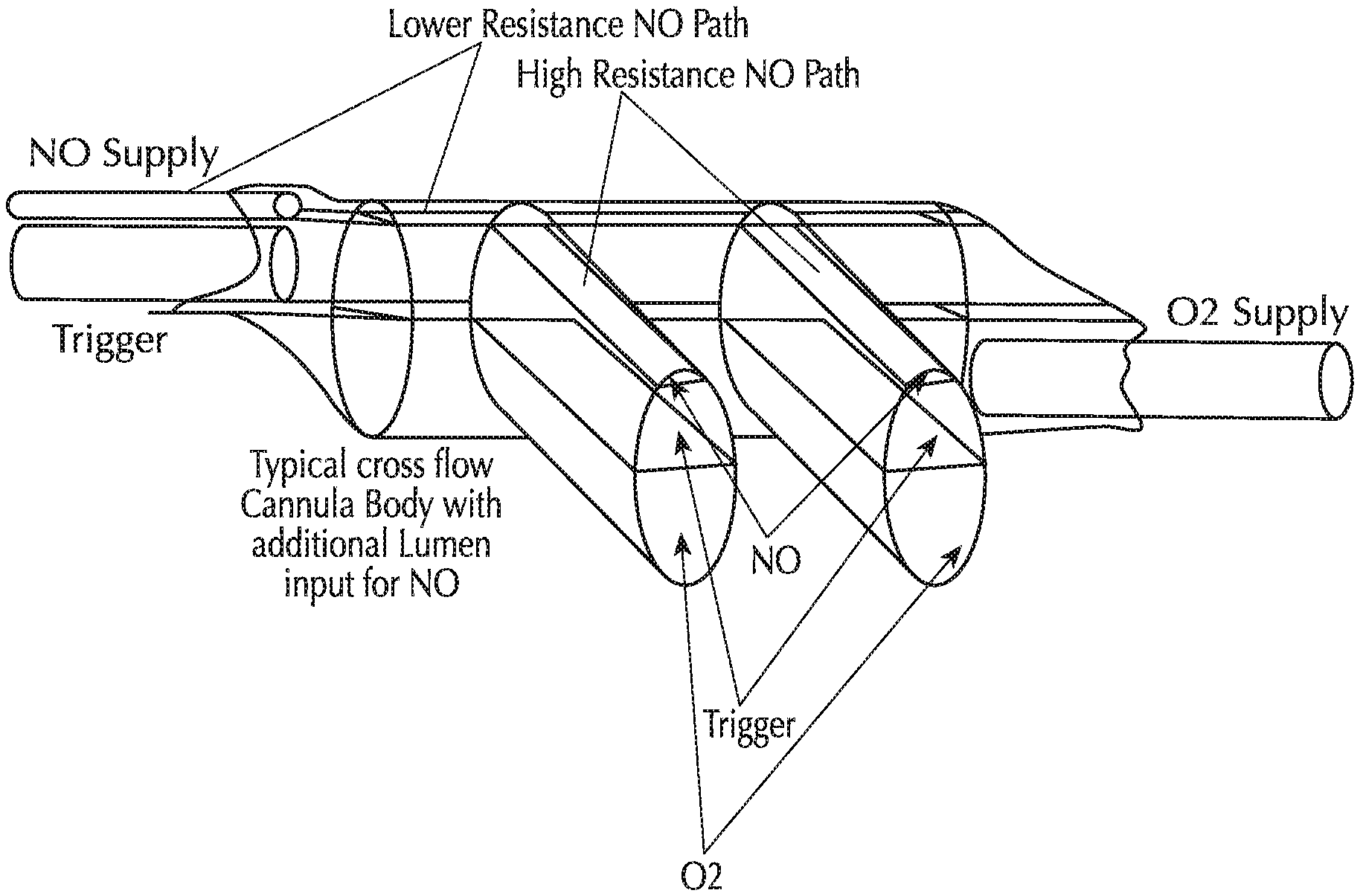
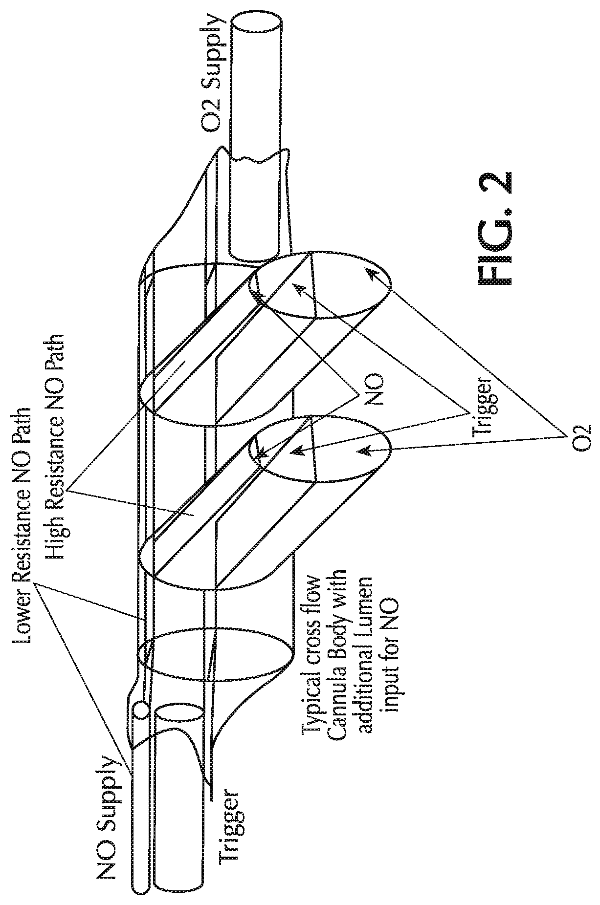
FIG. 2 shows three lumina integrated into a single cannula head;
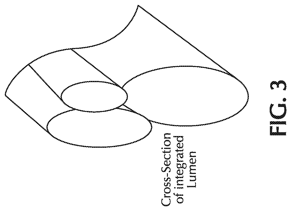
FIG. 3 shows a cross-section of an integrated three-lumina cannula;
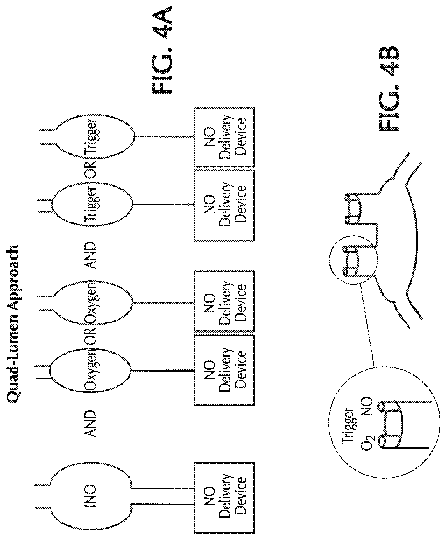
FIGS. 4A and 4B show the pneumatic paths for the NO, oxygen and trigger lines in a quad-lumen cannula;
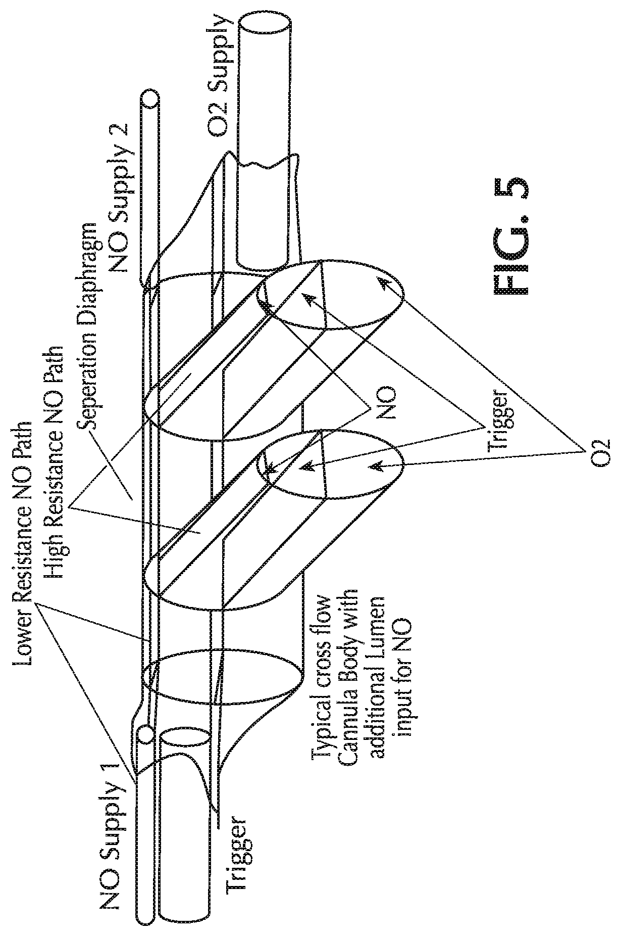
FIG. 5 shows four lumina integrated into a single cannula head;
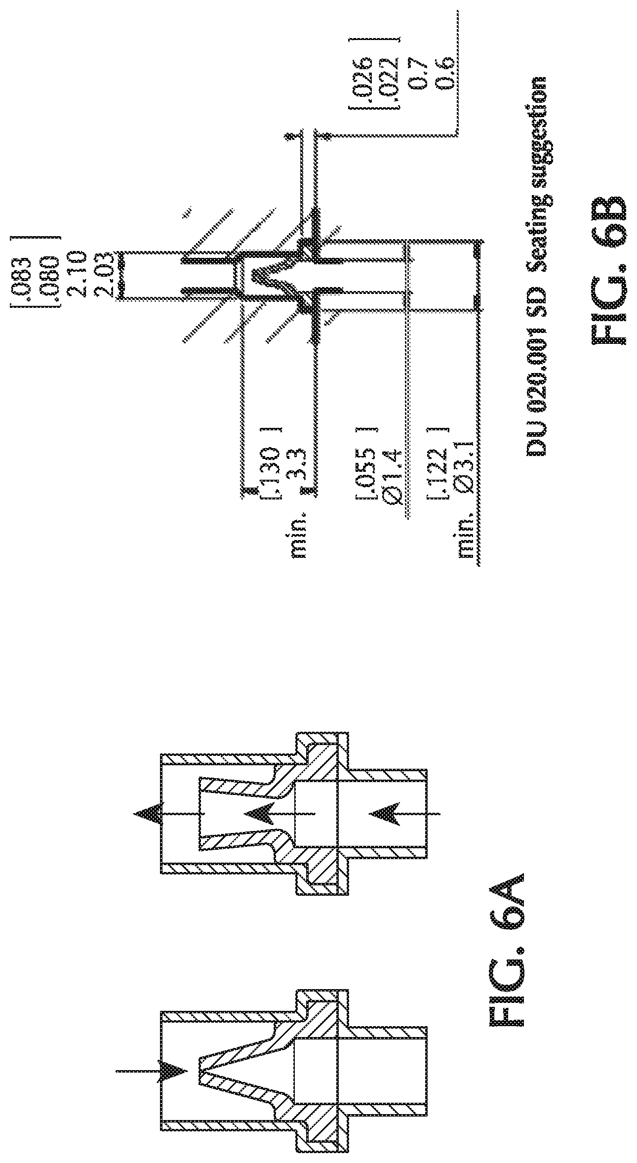
FIGS. 6A and 6B show details of duck bill check valves;
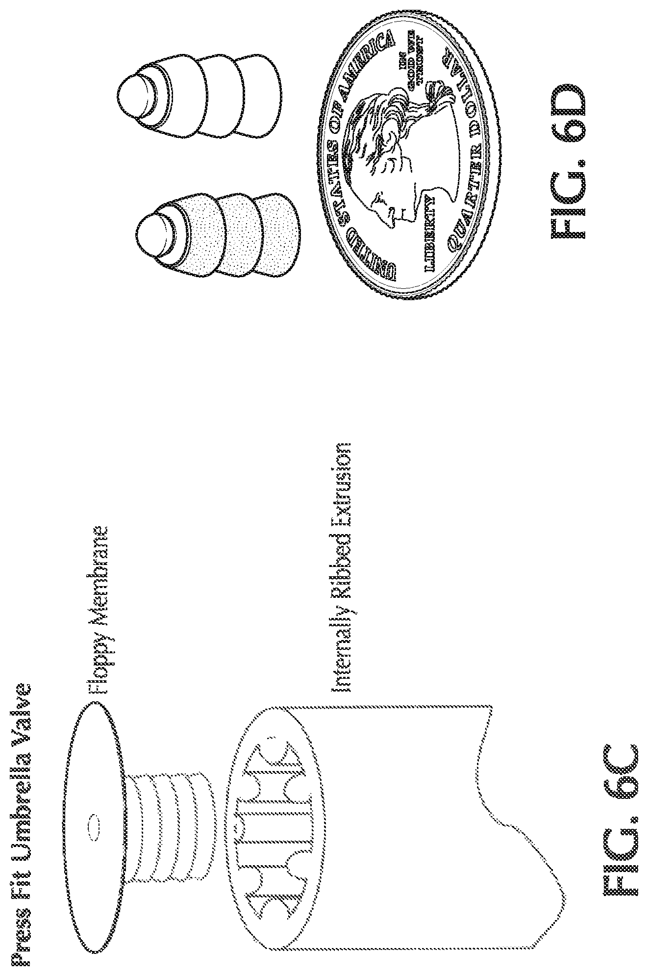
FIGS. 6C and 6D show details of umbrella check valves;
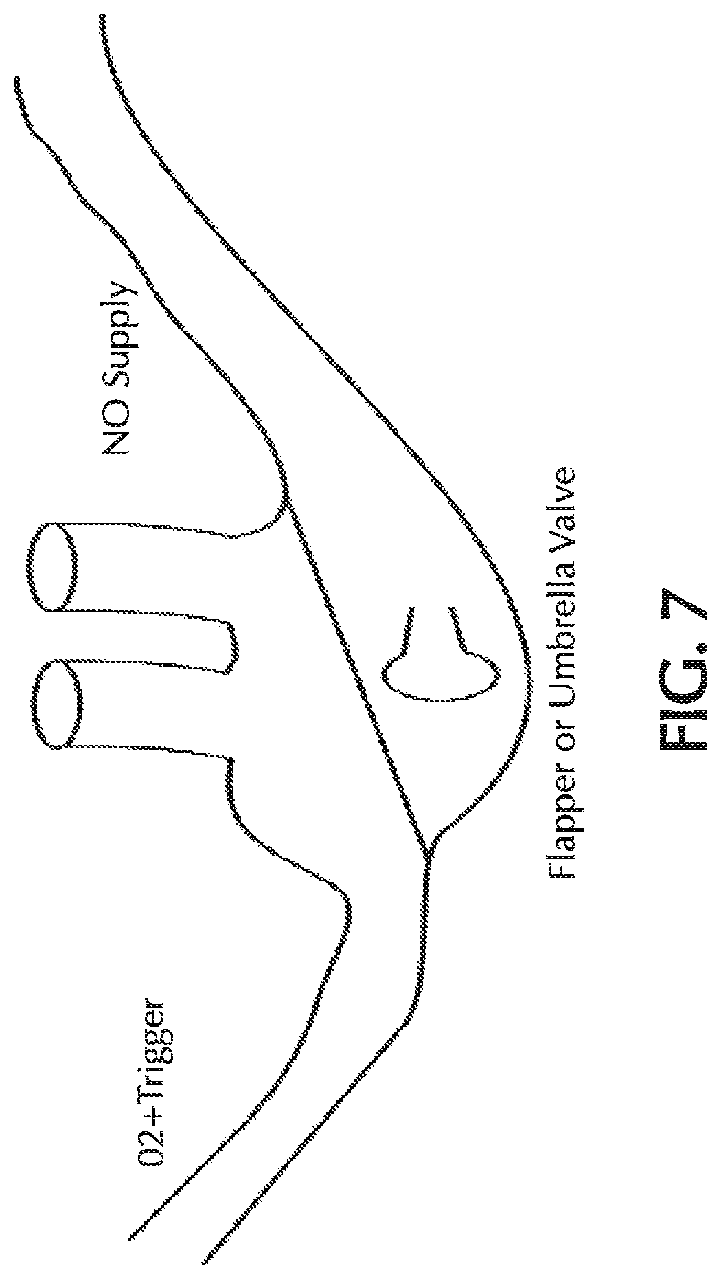
FIG. 7 shows a nasal cannula with an umbrella or flapper valve for delivering NO;
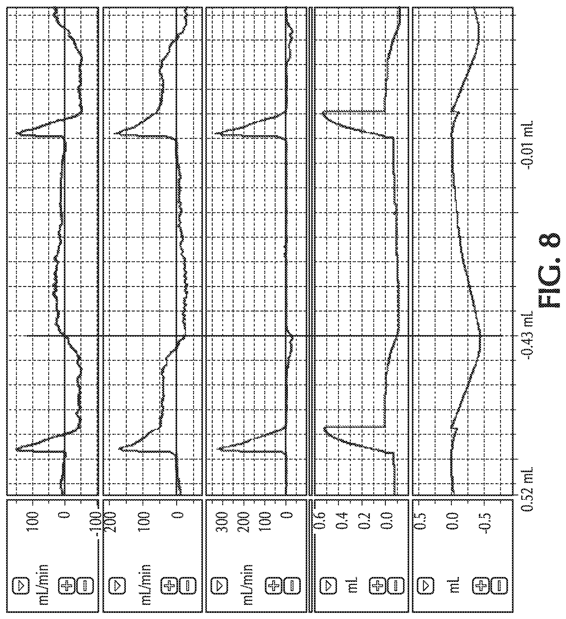
FIG. 8 shows retrograde flow during inspiratory breathing along with pulsed delivery;
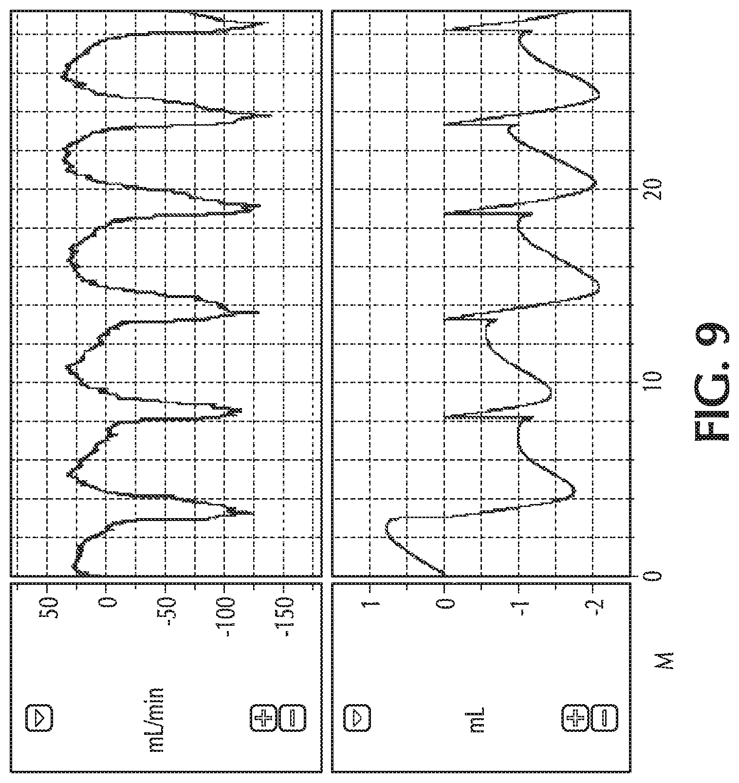
FIG. 9 shows retrograde flow during both inspiratory and expiratory breathing;
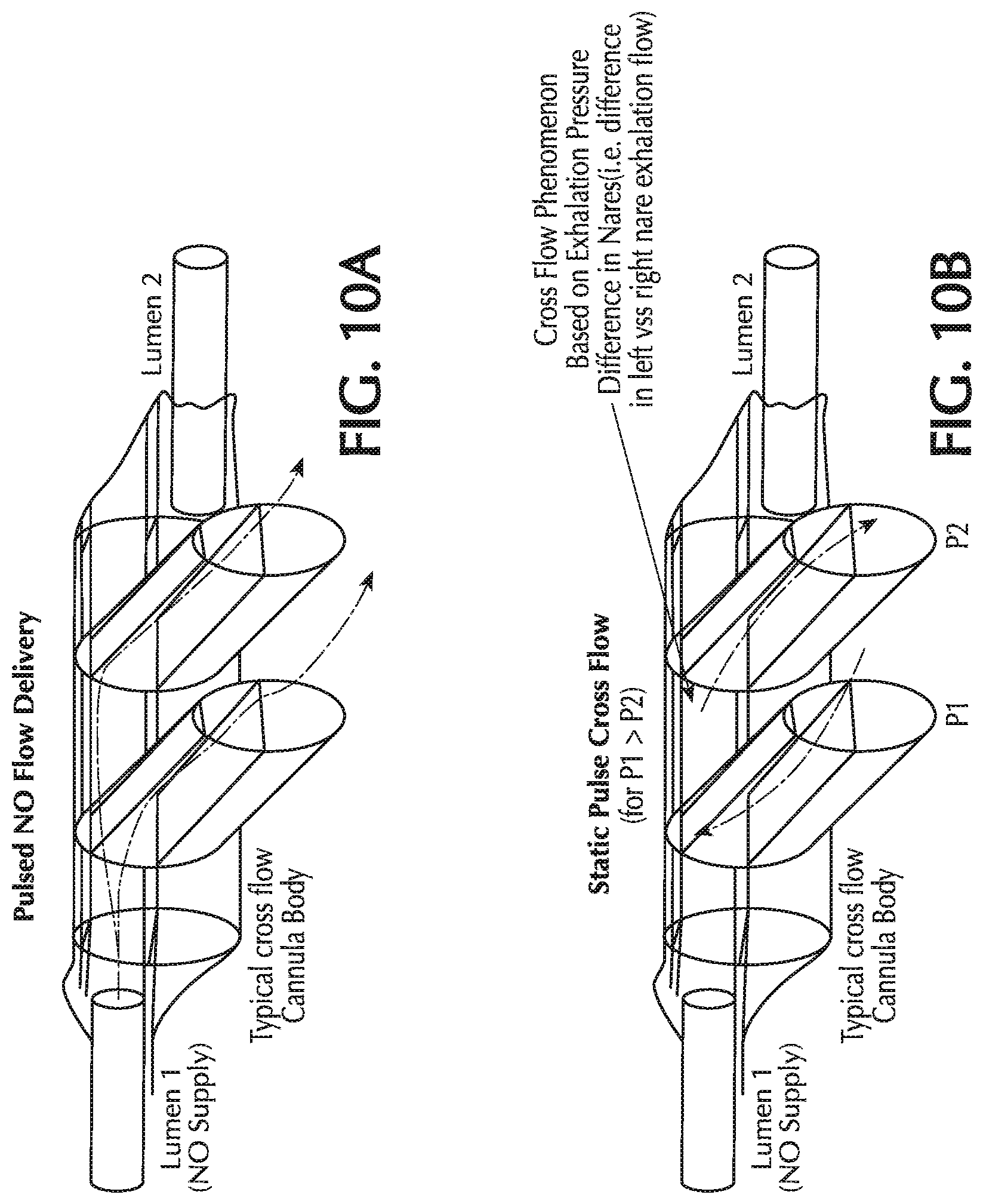
FIGS. 10A and 10B show cross-flow between two nasal cannula prongs;
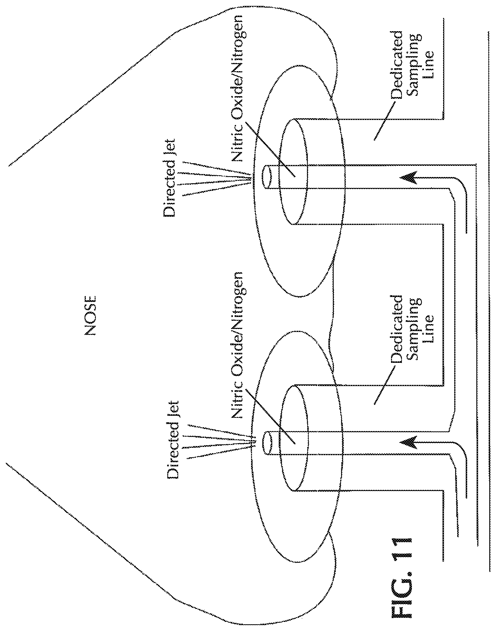
FIG. 11 shows a nasal cannula with two lumina of different sizes;
FIGS. 12A and 12B show two embodiments of incorporating a valve into the NO delivery line;
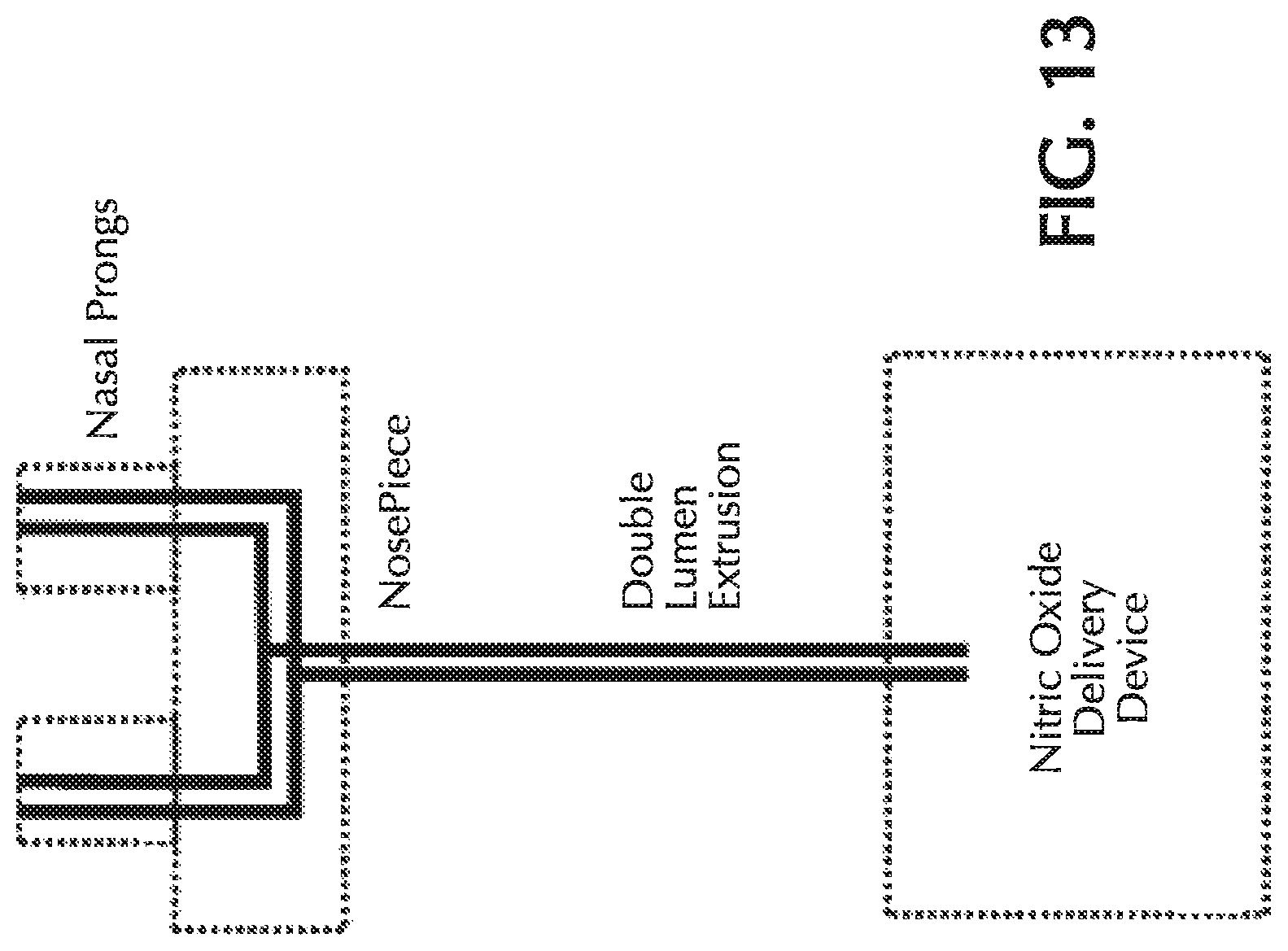
FIG. 13 shows a dual-lumen cannula for co-delivering NO and O.sub.2;
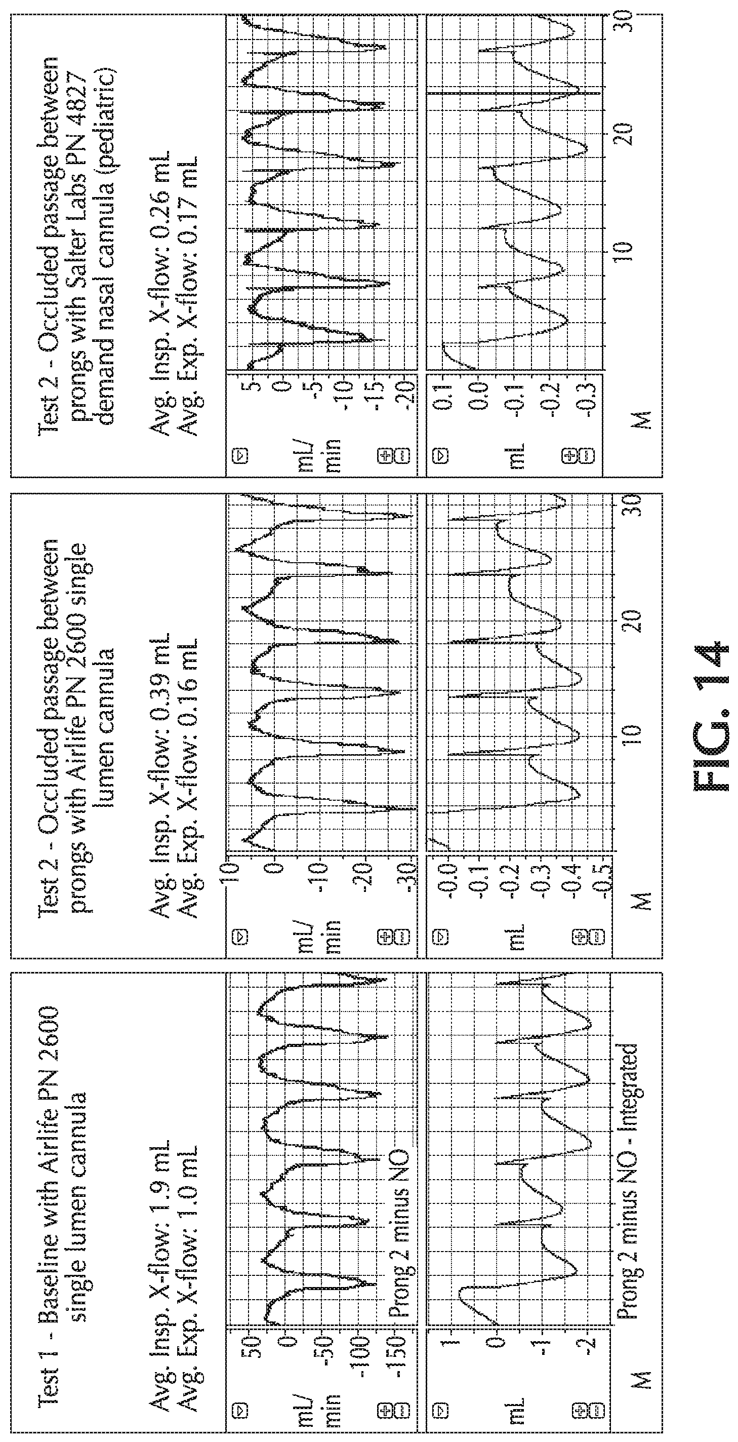
FIG. 14 shows retrograde flow for various cannula configurations;
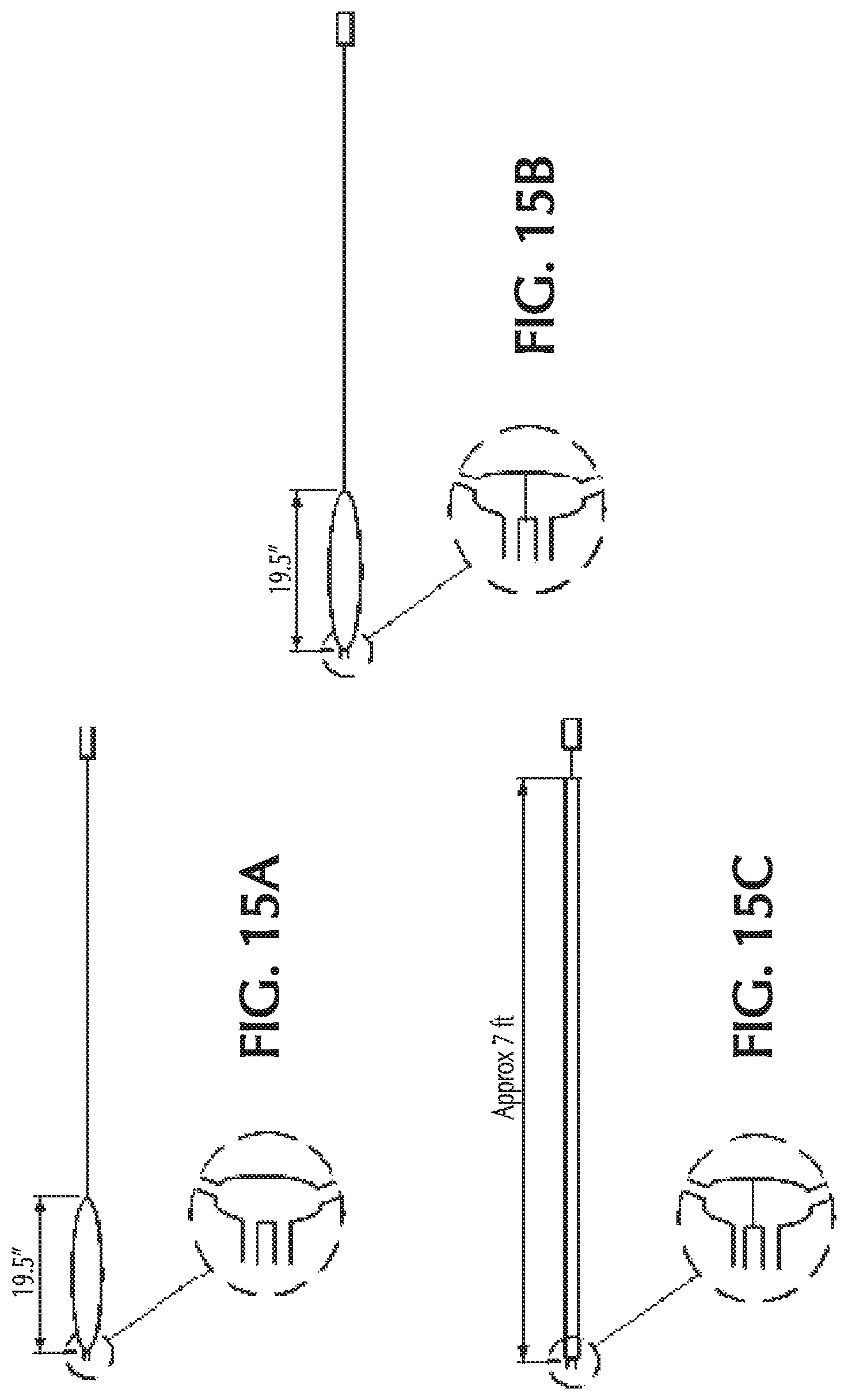
FIGS. 15A-C show the cannula configurations for Tests 1-3 of FIG. 14;
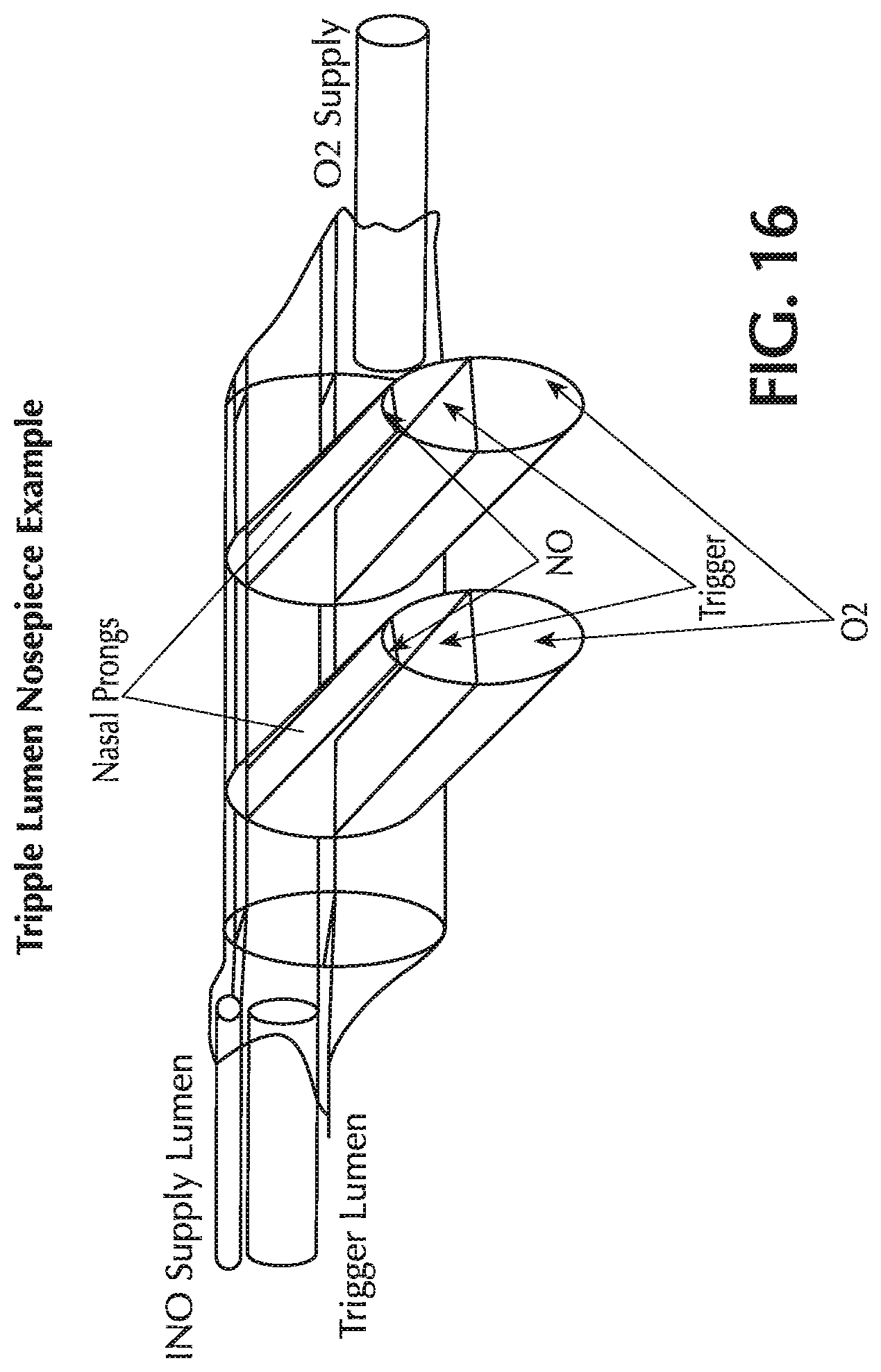
FIG. 16 shows a nasal cannula with a triple lumen nosepiece;
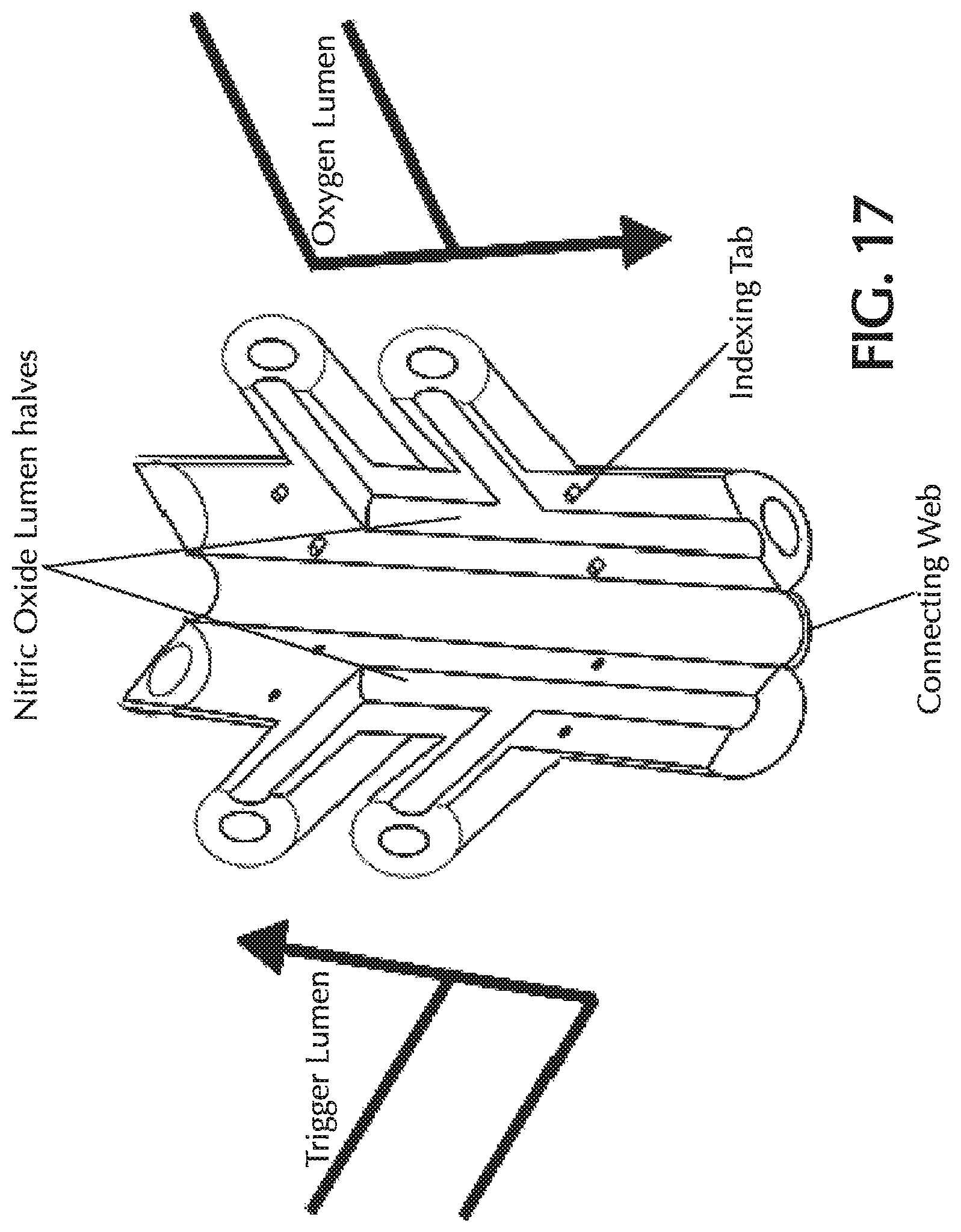
FIG. 17 shows a molded triple lumen nosepiece prior to assembly;
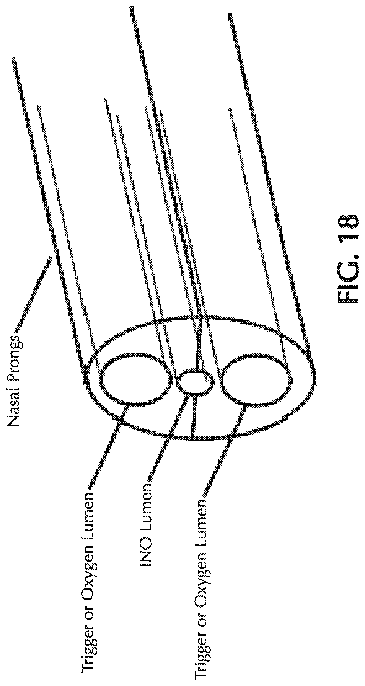
FIG. 18 shows the nasal prong of the assembled molded triple lumen nosepiece; and
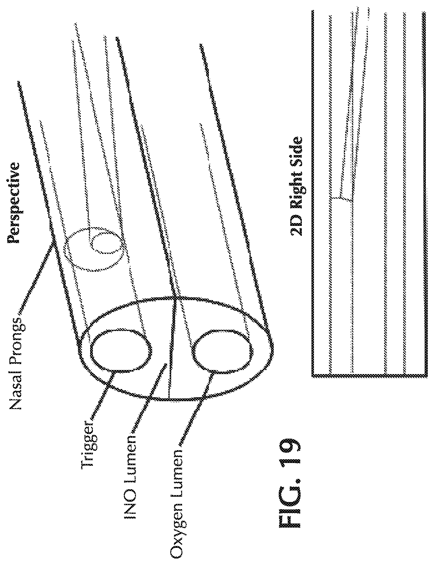
FIG. 19 shows a perspective and a two-dimensional representation of a nasal prong with a NO lumen proximal to and within a trigger lumen.
DETAILED DESCRIPTION
Methods of delivering inhaled nitric oxide (NO) should ideally be optimized to ensure accurate and consistent delivery of the dose to the patient. Typically, NO is delivered at relatively low volumetric percent concentrations in a carrier gas. Nitrogen is a common carrier gas for NO delivery because nitrogen is non-reactive with NO, but other inert carrier gases such as helium may be used. Delivery of the NO/N.sub.2 gas mixture to the patient typically requires that the gas travel from a high pressure NO source (such as a pressurized cylinder) to the patient at or near ambient pressure by means of a respiratory tube for ICU ventilator bound or anesthesia patients or a nasal cannula for spontaneously breathing patients. This travel of the NO is ideally devoid of contact with other gasses, such as ambient air, oxygen, carbon dioxide, etc., until the gas enters the patient's upper respiratory tract. However, in practice, this is not easily achieved. Specifically, oxygen and ambient air can enter the delivery system at a number of points as follows: During the connection of the high pressure source (typically cylinder) to the delivery device During the NO gas transit through the cannula (by way of diffusion across the cannula wall) During the inhalation/exhalation cycle when a driving pressure gradient seeks to reverse flow in the nasal cannula NO supply lumen producing mixing within the cannula with ambient air
The dilution of NO during pulsed NO therapy may be problematic because only a small volume of NO is delivered to the patient. For example, the NO-containing gas may be administered in pulses less than 1 mL. With small pulse volumes, even small volumes of retrograde flow or diffused gases may be significant because the NO dose may be diluted.
Materials:
One or more embodiments of the present invention relate to a nasal cannula that addresses one or more of these above sources of oxygen/NO contact and thereby dilution of the intended NO dose. One particular source of oxygen that may be minimized is the transit of oxygen across the cannula walls. In one or more embodiments, a cannula is provided that includes a smaller inside diameter (ID) delivery tube/lumen for NO. This smaller ID tube reduces the transit time of the NO molecules through the cannula, thereby reducing the time available for oxygen to diffuse across the walls of the cannula and oxidize the internal NO into NO.sub.2.
Another approach to minimize the oxygen contact provided by oxygen diffusion across the cannula walls is to use a wall material that minimizes the oxygen diffusion rate. Accordingly, in some embodiments, the cannula wall comprises a material with a low oxygen diffusion coefficient. Polyvinyl chloride (PVC) is currently a common material for constructing nasal cannulas, but it is not optimal for reducing oxygen diffusion through the cannula walls. Accordingly, some embodiments provide using urethane or another similar soft material. In some embodiments, the urethane or other soft material includes an additive to enhance the resistance to oxygen diffusion. Examples of suitable additives include oxygen resistant polymers such as polyvinylidene chloride (PVDC), ethylene vinyl alcohol (EVOH), polyamide (PA) or similar materials. Alternatively, PVC may be used as the cannula material, but one or more additives such as oxygen resistant polymers may be incorporated to reduce the oxygen diffusion coefficient of the material. The oxygen resistant polymers may be incorporated into the urethane or other cannula material through co-extrusion. Such an extrusion may be achieved with a dual head extruder.
Pneumatic Configurations:
Another potential source of nitric oxide dilution is from retrograde flow in the nasal cannula. Retrograde flow, also known as cross flow, is a phenomenon in which ambient air flows in opposite directions between the two delivery prongs of the nasal cannula. As shown in FIG. 10A, during normal pulsed delivery, NO flows out of both nasal prongs of the cannula. However, during the static phase between pulses, ambient air can flow in a circular motion in through one prong and out the other prong as shown in FIG. 10B. The degree of retrograde flow depends on the pressure difference between the nares during both the inhalation and exhalation phase. The pressure difference between the nares can vary depending on the person's breathing pattern, placement of the nasal prongs and the degree of misbalance between the nasal flow during breathing. Retrograde flow results in dilution and washout of the NO in the nasal prongs and flow path. This can cause a delay or reduction in the delivered dose. Furthermore, air may react with nitric oxide in the nasal cannula, thus forming NO.sub.2 and further diluting the NO concentration.
Accordingly, aspects of the present invention also provide nasal cannulas that may minimize the retrograde flow in the nasal cannula. Such nasal cannulas may include a means of delivering oxygen and therapeutic gas containing NO, and may be able to transmit pressure transients associated with inhalation-based gas flow triggering. If the cannulas deliver oxygen in addition to NO, the oxygen may be provided by an oxygen conserver or an oxygen concentrator.
In one or more embodiments, the nasal cannula has two lumina (i.e. a dual-lumen cannula). FIG. 11 shows an exemplary dual-lumen cannula that delivers nitric oxide in a separate lumen than is used to deliver oxygen and/or trigger the delivery device. The NO lumen carries therapeutic gas comprising NO from the NO delivery device to the patient. The trigger lumen does not deliver gas to the patient, but instead establishes fluid communication between the patient's nares and a trigger sensor in the NO delivery device. When the patient begins a breath, a drop in pressure occurs in the nares. This pressure signal is communicated through the trigger lumen to the trigger sensor, which then senses that the patient has begun inspiration. The trigger sensor can then send a signal to a CPU in the NO delivery device so that the CPU will open a control valve to deliver NO to the patient, such as a pulse of NO in a carrier gas.
As shown in FIG. 11, in some embodiments the lumen that carries the nitric-oxide containing gas may have a smaller inner diameter than the other lumen such as the triggering lumen. In these embodiments, the cannula may reduce dilution by at least two potential mechanisms: 1) the cannula may minimize mixing of oxygen and NO by two means, first a reduction in retrograde flow into the small ID NO carrying lumen due to the smaller, ID, second the volume of gas per unit length is reduced thereby reducing the bulk volume of gas mixing occurring; and 2) the narrow ID produces a narrow jet of gas flow which effectively minimizes O.sub.2/NO mixing during NO delivery until much further into the nasal cavity. The diameter of the small lumen may be minimized by engineering design such that it is as small as reasonably possible without producing confounding upstream effects on the flow delivery mechanics of the device. In some embodiments, the ratio of the ID of the NO lumen to the ID of the trigger lumen may be 1:1, 1:1.2, 1:1.3, 1:1.5, 1:2, 1:2.5, 1:3, 1:3.5, 1:4, 1:4.5, 1:5, 1:5.5, 1:6, 1:7, 1:8, 1:9, 1:10, 1:12, 1:15, 1:20, 1:25 or 1:30.
Also, the geometry of the nasal cannula lumina may be optimized to prevent retrograde flow. Thus, in addition to circular or parabolic cross-sections, the cross-section of any of the nasal cannula lumina described herein may be square, rectangular, triangular or any other regular or irregular shape to minimize dose dilution. When one or more cross-sectional areas are not circular, then the ratio of inner diameters may be the square root of the ratio of the surface areas of the two lumina sections.
Alternatively, a dual-lumen cannula may have a first lumen for oxygen delivery and a second lumen for delivery of NO and transmitting the pressure signal for the trigger sensor. Such a two lumina configuration is shown in FIG. 13. In this configuration, the first lumen carries oxygen from the oxygen conserver/concentrator to the nosepiece of the cannula. The second lumen delivers NO from the nitric oxide delivery device to the patient and delivers the pressure-based triggering signal from the patient to trigger sensor of the nitric oxide delivery device. Both lumina would be constructed to "tee" to both nares and thus be in unobstructed fluid communication with both nares as shown in FIG. 13.
The first lumen for carrying oxygen may be constructed with lumen inner diameter geometry consistent with industry norms. For instance, nasal cannulas with rated 6 LPM oxygen delivery capacity typically provide an oxygen lumen inner diameter of approximately 0.080'' at or near the nosepiece.
The second lumen of the dual-lumen cannula may have a geometry unique to the gas delivery objectives of the nitric oxide delivery system. Nitric oxide delivery systems which pulse nitric oxide gas into the patient are believed to have optimal clinical efficacy when a pulse or flow of nitric oxide is delivered to the patient as early in the inspiratory phase as possible. Therefore, any pneumatic delays would not be optimal. Further, the shape of the flow waveform as delivered by the nitric oxide delivery system is, optimally, not distorted during transit from the device to the patient. In addition, the transit of the pressure signal from the patient indicative of inspiratory effort preferably is not delayed/distorted when in transit from the patient back to the device. Finally, the volume of potential nitric oxide mixing with either exhaled gas or ambient gas is preferably minimized to reduce the potential for oxidation of nitric oxide at the nosepiece of the cannula, which again can produce NO.sub.2 which dilutes the NO dose and is a known respiratory irritant.
In order to achieve the goals described above for the second lumen, there are several competing metrics of lumen ID optimization as noted below: a. Reduce NO.sub.2 formation.fwdarw.Reduce lumen ID b. Maintain volumetric NO dosing accuracy.fwdarw.Reduce lumen ID c. Reduce NO flow distortion.fwdarw.Lumen ID within certain bounds d. Minimize trigger signal attenuation or delay.fwdarw.Increase lumen ID
Therefore, an optimal inner diameter dimension of the second lumen would address all of these concerns to ensure adequate device performance. Such optimal ID dimensions may vary depending on the volume of NO-containing gas delivered by the nitric oxide delivery device. For example, a nitric oxide delivery device may deliver pulses of NO-containing gas with a minimum dose volume of 0.35 mL. In order to ensure volumetric dosing accuracy, it is preferable that no more than 10% of the dose can be lost due to ambient bleed of NO in between inspiratory efforts. Such a bleed can occur during the exhalation phase in which imbalances in the flow out of the nostrils results in a "high flow nostril" and a "low flow nostril." Flow into the prong from the high flow nostril may result in flow of out of (gas loss out of) the prong of the low flow nostril. This gas, which is located in the "U" shaped portion of the tee'd lumen, is lost to ambient during the exhalation phase and would consist of NO therapeutic gas. Therefore, one or more embodiments of the present invention limit the internal volume of this "U" shape to be no more than 10% of the minimum dose volume (i.e. 0.035 mL for a 0.35 mL pulse of therapeutic gas), thus ensuring acceptable NO loss to ambient during the exhalation phase. Such a requirement of 0.035 mL requires a lumen ID within the "U" segment of no more than 0.046'' given a prong length of 8 mm and a prong spacing of 16 mm. Therefore, a lumen ID significantly larger than 0.046'' would not be advantageous to maintaining dose volume accuracy for minimum dose volumes of 0.35 mL. Of course, it is understood that the mathematics of this construct would be modified by systems with larger or smaller minimum dose volumes appropriately, or with different prong lengths and/or prong spacing. One skilled in the art can perform the required calculations to determine the ID required to provide a desired volume in the "U" section so that it does not exceed 10% of the dose volume. Furthermore, depending on the required accuracy for the dosing, the internal "U" volume or other volume available for cross-flow may be less than 50%, 45%, 40%, 35%, 30%, 25%, 20%, 15%, 10%, 5%, 4%, 3%, 2% or 1% of the dose volume.
In addition to the volumetric dosing accuracy concern, another concern is that the second lumen ID not produce gas flow distortion. However, given that gas flow in a nitric oxide system may use restrictors which are significantly smaller in inner diameter than a NO lumen ID of 0.046 inches, such distortion may not actually occur.
Finally, the inner diameter of the second lumen preferably does not produce undue signal propagation delay from the patient to the device. Such delay is believed to occur as pneumatic tubes behave as first order pneumatic low pass filters and attenuate higher bandwidth signal components. Modification of the inner diameters is known to change the band pass characteristics of the filtering effect. However, as noted earlier, the inner diameter (at the U) may be fixed to a certain maximum ID based on the required dose delivery accuracy of the system. Therefore, in order to minimize the effects of the potentially frequency attenuated pressure signal, two measures can be taken. First the upstream (close to device) diameter of the second lumen may be adjusted to widen (optimize) the band pass characteristics of the cannula. This may ensure that unneeded compressible volume is unavailable upstream of the nose piece restriction (0.046'' ID restriction). This reduces the compressible volume in the cannula and effectively increases the bandpass characteristics of the cannula. The second measure which can be taken is to trigger the initiation of pulse delivery on the device not based on a threshold pressure level (the magnitude of which can which can be delayed by frequency attenuation) but by triggering the device based on a pattern of sloping pressure indicative of patient effort. Such a slope may be reduced in magnitude by the filtering characteristics of the tubing, however, the slope will still be present for algorithmic triggering decisions by the device. However, such a triggering implementation is optional.
Accordingly, in some embodiments, the dual lumen cannula would have an oxygen lumen in the range from 0.05 to 0.12'' ID (such as about 0.080'' ID) which tees at the nosepiece and is in fluid communication with both nares. It would also have a second (nitric oxide) lumen (similarly in fluid communication with both nares) with an internal tubing diameter dictated by volumetric dosing accuracy considerations and the second lumen may have an ID in the range from 0.01 to 0.08'' (such as about 0.046'' ID) with upstream tubing adjusted to optimize the bandpass performance of the system. Finally, device triggering methodologies based not on pressure thresholds, but based on pressure slope trends can also be employed to improve overall timely delivery of dosing to the patient.
Other pneumatic configurations for the nasal cannula may utilize different numbers of lumina. In one or more embodiments, the nasal cannula has three lumina (i.e. a tri-lumen cannula). FIG. 1A shows an exemplary set of pneumatic paths of the three individual lumen from a nitric oxide delivery device to the patient. The three lumina may include a NO lumen, a trigger sensor lumen and an oxygen lumen. The oxygen lumen carries an oxygen-enriched gas (such as oxygen-enriched air or substantially pure oxygen) from an oxygen source to the patient. The oxygen source may be a typical oxygen pulsing device, or may be a port on the NO delivery device that delivers the oxygen-enriched gas. FIG. 1B shows the three lumina aggregated into a single cannula. In FIGS. 1A and 1B, the NO lumen is tee'd at some point between the patient and the NO delivery device. Further, the oxygen and trigger lumina are also tee'd at some point between the device and the patient and might be tee'd in two locations, such as having an additional tee in the cannula head at the two nasal prongs.
Again, all three of the lumina may be integrated into a single cannula. FIG. 2 shows one such method for integration of the three lumina at the head (nose bridge fitting) of the cannula. The separation of the pneumatic paths or lumina in FIG. 2 is by means of partitions or diaphragms within the head and prongs of the cannula. The NO supply traverses to the head through a lower gas resistance source to higher resistance orifices integrated into the prongs of the cannula. All lumina are separated by a diaphragm partition within the head of the cannula and within the prongs of the cannula, which prevents mixing of the fluid streams in the separate lumina.
The tubes of the cannula carry backwards towards the patient and may be affixed to each other so as to produce a clean single element umbilical between the cannula head and the device as shown in FIG. 3, which provides a cross-section. Alternately, the three lumina can be extruded through a single die producing a multi-lumen tube.
As can be seen from FIG. 2, the NO delivery tube may decrease in inner diameter (ID) once the tubing enters the head of the nasal cannula. Accordingly, in one or more embodiments, the pneumatic resistance is greater in the prongs of the nasal cannula than in the tubing carrying the NO from the NO delivery device to the cannula head. Such a device may have many advantages. In some embodiments, the smaller ID tubing of the dedicated NO delivery lumen will allow for: Short gas transit times Reduced inspiratory/expiratory phase retrograde flow of ambient air into the lumen (reduced according to Knudsen diffusion which states that diffusion rate is proportionate to the mean free path length of the gas molecule which is reduced with smaller ID) Increased gas resistance to flow (smaller ID tubing produces gas flow resistance which is inversely proportional to the fourth power of tubing radius by Poiseuille's Law). Reduced volume in the tee'd loop of the NO delivery lumen
All of the above may serve to reduce the potential for retrograde flow and/or reduce the volume of retrograde flow and/or reduce the contact or contact duration between NO and other gasses including oxygen in the cannula. This will reduce the dilution of NO and thereby increase the precision of the delivered NO dose.
The ID of the NO lumen may decrease from a maximum ID to a minimum ID. In some embodiments, the ratio of the minimum ID to the maximum ID of the NO lumen may be 1:1, 1:1.2, 1:1.3, 1:1.5, 1:2, 1:2.5, 1:3, 1:3.5, 1:4, 1:4.5, 1:5, 1:5.5, 1:6, 1:7, 1:8, 1:9 or 1:10.
The trigger lumen ID may be comparatively much larger than the NO lumen ID. Trigger pressure drop on inhalation must be transmitted through this cannula lumen with the smallest possible loss of signal magnitude to the NO delivery device which in turn uses this pressure signal to deliver pulsed NO. Again, in some embodiments, the ratio of the ID of the NO lumen to the ID of trigger lumen may be 1:1, 1:1.2, 1:1.3, 1:1.5, 1:2, 1:2.5, 1:3, 1:3.5, 1:4, 1:4.5, 1:5, 1:5.5, 1:6, 1:7, 1:8, 1:9, 1:10, 1:12, 1:15, 1:20, 1:25 or 1:30.
The oxygen lumen may also be larger than the NO lumen to minimize oxygen flow resistance and to reduce gas flow speed at the prongs which could serve to interfere with the triggering pressure signal due to gas flow effects such from Bernoulli's principle. As with the trigger lumen, in some embodiments the ratio of the ID of the NO lumen to the ID of the oxygen lumen may be 1:1, 1:1.2, 1:1.3, 1:1.5, 1:2, 1:2.5, 1:3, 1:3.5, 1:4, 1:4.5, 1:5, 1:5.5, 1:6, 1:7, 1:8, 1:9, 1:10, 1:12, 1:15, 1:20, 1:25 or 1:30.
Another pneumatic configuration is shown in FIGS. 4A and 4B. Like the pneumatic configurations shown in FIGS. 1A and 1B, this configuration separates the pneumatic paths of the NO, oxygen and trigger. However, unlike the configuration shown in FIGS. 1A and 1B, in the configuration shown in FIGS. 4A and 4B, the NO flow delivery paths to each nostril are kept separate and distinct and have their own pneumatic delivery source at the NO delivery device. Accordingly, this configuration has four lumina (i.e. a quad-lumen cannula).
One potential benefit of the quad-lumen approach is to prevent movement of gas through the tee'd delivery loop of the NO supply line during exhalation. This may reduce NO/oxygen contact. However, unlike the tri-lumen cannula, use of the quad-lumen cannula may require dedicated pneumatic circuitry for each NO lumen.
FIG. 5 shows one potential method for achieving this configuration at the cannula head. As with the tri-lumen cannula, the quad-lumen cannula fuses the lumen of the cannula into a single umbilical between the cannula head and the device.
With any of the pneumatic configurations described herein, there may be other modifications of the cannula to improve NO dosing. In one or more embodiments, provided is a nasal cannula with one or more check valves in the nitric oxide delivery line. This configuration may be combined with one of the multi-lumen configurations described above. The check valves(s) help to prevent retrograde gas movement into the NO supply lumen during inhalation/exhalation. Such a check valve might consist of any low cracking pressure check valve which is placed at some point in the NO delivery path. Such check valves may include, but are not limited to, duckbill valves or umbrella valves. Exemplary duck bill valves are shown in FIGS. 6A and 6B and exemplary umbrella valves are shown in FIGS. 6C and 6D. These check valves may be miniature check valves so to have the proper dimensions to fit in the NO delivery lumen.
In one or more embodiments, provided is an NO delivery cannula having a small flapper or umbrella check valve at the head of the cannula allowing pulses of NO to be delivered to the general nose/mouth area during device NO pulsing. An exemplary configuration of a nasal cannula with such a flapper or umbrella valve is shown in FIG. 7. This configuration would allow NO to flow into either/both open nares upon inhalation. The O.sub.2 and trigger lumen may be combined (as shown in FIG. 7) or kept separate to improve the signal-to-noise performance of the trigger lumen. Such a configuration with the flapper valve would prevent retrograde flow of oxygen into the NO delivery path thereby reducing the potential for dilution of the dose. A diaphragm or other barrier separates the NO delivery line from the O.sub.2/trigger line at the cannula head to prevent mixing.
This pneumatic configuration may be combined with any of the other pneumatic configurations described above.
In one or more embodiments, also provided is a nasal cannula incorporating an impermeable or semi-permeable membrane. The membrane may be movable or fixed but can be actively or passively moved when needed, that separates the NO containing gas or material from the O.sub.2 containing gas or material until the NO needs to be delivered to the patient. This membrane may reduce one or more of the contact time, surface area and diffusion rate between the NO and O.sub.2 containing gases. This may reduce the formation of NO.sub.2, which dilutes the intended NO delivery concentration.
In some embodiments of the membrane, a normally-closed valve at the tip of the NO containing cannula prevents air from contacting the NO containing gas inside the cannula until the valve opening is triggered (e.g. by a drop in pressure caused by inhalation by the patient or by the positive pressure caused by the delivery device as it attempts to deliver the NO containing gas to the patient). When the valve opening is triggered, the NO is then delivered to the patient. One embodiment of such a valve is shown in FIG. 12A.
In one or more embodiments, also provided is a system to expel the gas or other NO containing material that does come in contact with O.sub.2 containing gas or material, which may have otherwise formed NO.sub.2 in this mixture. The system may subsequently allow another part of the NO containing gas or material that has minimal or no NO.sub.2 to be delivered to the patient Again, this NO.sub.2 formation could serve to dilute the NO dose before delivery to the patient.
In some embodiments of this system, this system may comprise an electromechanical valve system that actuates to pump out a fixed or adjustable amount of gas mixture that might contain NO.sub.2 through a separate orifice than the cannula opening to the patient. The system may then actuate to pump the NO containing gas or material to the patient. One embodiment of such a system is shown as a 3-way valve in FIG. 12B.
The membrane and/or valve system may be combined with any of the other pneumatic configurations described above.
Manufacturing of Multi-Lumen Nasal Cannulas
As described above, the individual lumen of a multi-lumen cannula may be separately manufactured and then affixed to each other, or the multiple lumina can be extruded through a single die producing a multi-lumen tube.
According to one or more embodiments, the multi-lumen nosepiece of the multi-lumen cannulas described herein may be manufactured by the following molding technique. For example, the cannula may have a triple lumen cannula nosepiece for separate oxygen, nitric oxide and triggering lumina. In one or more embodiments, the design of the nosepiece for the triple lumen cannula involves three lumens, two with inner diameters of approximately 0.080'' (for oxygen and triggering) and one with a smaller inner diameter of approximately 0.045'' (for nitric oxide) as shown in FIG. 16. However, this configuration may not be readily molded by typical injection molding techniques as the small lumen would require an injector pin (of outer diameter 0.045'') which is too small to be robust in a molding tool designed to last for many uses, such as a million or more shots.
Accordingly, one approach to manufacture the multi-lumen cannula nosepiece is to mold two halves in urethane, PVC, silicone or other low durometer elastomer with the internals of the large lumen defined by larger injector pins (outer diameter 0.080'') and with small half lumen indents defining the outline of the small lumen. These two halves would then be folded and bonded together, preferably with a bonding technique which does not produce residue or flash such as RF welding, to form a whole nosepiece. FIG. 17 shows one embodiment to circumvent the injector pin limitation with the small ID lumen being defined by indents in the halves, the two halves would be molded flat in one shot with a webbing holding the halves together and providing gross alignment during the folding and bonding process. Optionally, the molded halves may comprise integral holes and mating cylindrical tabs or other complementary members so that the halves will be properly aligned when they are folded together. The webbing may also be optional if appropriate complementary indexing members on the two halves ensure that the two portions forming the outer wall of the NO lumen will be properly aligned. The assembled nosepiece allows for three lumen inputs and tee's each lumen input within the internals of the nosepiece proper. FIG. 18 shows a perspective view of the nasal prong of the multi-lumen cannula nosepiece of FIG. 17 after the two halves have been assembled.
Again, the lumen ID may be adjusted as described in the previous sections. For example, the ID of the oxygen lumen may range from 0.05 to 0.12'', the ID of the trigger lumen may range from 0.05 to 0.12'', and the ID of the NO lumen may range from 0.01 to 0.08''. In some embodiments, the IDs of the oxygen lumen and the trigger lumen may both be in the range from 0.07'' to 0.09'' (such as about 0.08'') and the ID of the NO lumen may be in the range from 0.035 to 0.055'' (such as about 0.045'').
An alternate embodiment shown in FIG. 19 involves ensuring that the small NO lumen exits proximal to and within the larger trigger lumen. This embodiment ensures that any tip blockage of the larger trigger lumen (for which there is not a purge capability) would be blown out by the function of the NO pulse. The geometry of this embodiment must be carefully modeled to ensure that all NO in the larger trigger lumen reaches the respiratory system during inspiration and is not left behind to be swept out during exhalation.
Methods of Treatment
Any of the nasal cannulas described herein may be used in nitric oxide therapy to treat appropriate diseases. For example, the cannulas may be for pulsed NO therapy to treat chronic obstructive pulmonary disease (COPD) or pulmonary arterial hypertension (PAH). For these diseases, the delivery of the appropriate dose amounts and appropriate dose timing may be very important. For COPD, the NO may need to be pulsed early in inspiration, such as the first half of inspiration. If NO is not delivered in the right amount or at the right time, reversal of hypoxic vasoconstriction may occur, which would worsen the patient's condition. Furthermore, the dose amount may be very important for PAH because sudden discontinuation of therapy can lead to serious events such as rebound hypertension. Thus, significant dilution of the NO dose should be minimized for these diseases. Any of the cannula materials, configurations or methods described herein may be used to minimize dilution of the NO dose during NO therapy.
Examples
FIG. 8 shows an example of retrograde flow during inspiratory breath along with pulsed delivery. FIG. 9 shows an example of retrograde flow during both inspiratory and expiratory breath.
The retrograde flow for various nasal cannula configurations was tested. Typical nasal cannulas that deliver to both nares result in significant retrograde flow as shown in Test 1 of FIG. 14. The nasal cannula configuration of Test 1 is shown in FIG. 15A. For Test 2, the interconnect between the two prongs was occluded to increase the distance between the prongs to approximately 19 inches in the hopes that would eliminate the retrograde flow. The nasal cannula configuration of Test 2 is shown in FIG. 15B. As shown in Test 2 of FIG. 14, while the total volume of retrograde flow could be reduced, it was not eliminated. Further occluding the pathway with a 7 foot distance between the prongs, as shown in FIG. 15C, had minimal further impact, as shown in Test 3 of FIG. 14. Surprisingly, it was found that the only way tested that completely eliminated the retrograde flow was when separate circuits were used for the NO delivery to each nare.
Reference throughout this specification to "one embodiment," "certain embodiments," "one or more embodiments" or "an embodiment" means that a particular feature, structure, material, or characteristic described in connection with the embodiment is included in at least one embodiment of the invention. Thus, the appearances of the phrases such as "in one or more embodiments," "in certain embodiments," "in one embodiment" or "in an embodiment" in various places throughout this specification are not necessarily referring to the same embodiment of the invention. Furthermore, the particular features, structures, materials, or characteristics may be combined in any suitable manner in one or more embodiments.
Although the invention herein has been described with reference to particular embodiments, it is to be understood that these embodiments are merely illustrative of the principles and applications of the present invention. It will be apparent to those skilled in the art that various modifications and variations can be made to the method and apparatus of the present invention without departing from the spirit and scope of the invention. Thus, it is intended that the present invention include modifications and variations that are within the scope of the appended claims and their equivalents.
* * * * *
D00000
D00001
D00002
D00003
D00004
D00005
D00006
D00007
D00008
D00009
D00010
D00011
D00012
D00013

D00014
D00015
D00016
D00017
D00018
D00019
D00020
XML
uspto.report is an independent third-party trademark research tool that is not affiliated, endorsed, or sponsored by the United States Patent and Trademark Office (USPTO) or any other governmental organization. The information provided by uspto.report is based on publicly available data at the time of writing and is intended for informational purposes only.
While we strive to provide accurate and up-to-date information, we do not guarantee the accuracy, completeness, reliability, or suitability of the information displayed on this site. The use of this site is at your own risk. Any reliance you place on such information is therefore strictly at your own risk.
All official trademark data, including owner information, should be verified by visiting the official USPTO website at www.uspto.gov. This site is not intended to replace professional legal advice and should not be used as a substitute for consulting with a legal professional who is knowledgeable about trademark law.