Systems and methods for identifying faulty touch panel having intermittent field failures
Young , et al. February 9, 2
U.S. patent number 10,915,204 [Application Number 16/377,854] was granted by the patent office on 2021-02-09 for systems and methods for identifying faulty touch panel having intermittent field failures. This patent grant is currently assigned to HAND HELD PRODUCTS, INC.. The grantee listed for this patent is Hand Held Products, Inc.. Invention is credited to Dennis Henry Cudzilo, John Yeschick, Timothy Young.


| United States Patent | 10,915,204 |
| Young , et al. | February 9, 2021 |
Systems and methods for identifying faulty touch panel having intermittent field failures
Abstract
An electronic device having a faulty touch panel may be diagnosed and indicated for repair by extracting a log from the electronic device. The log may include a record of touch panel events indicating active and inactive touch panel events divided into time periods. The log may be analyzed for touch panel events in a given time period. If a total number of touch panel events in a given time period exceeds a threshold count, and if a percentage of touch panel events in that given time period exceeds a threshold percentage, the touch panel may be identified as in need of replacement. Further, if a total number of touch panel events for all time periods exceeds a threshold percentage, the touch panel may be identified as in need of replacement.
| Inventors: | Young; Timothy (Clover, SC), Yeschick; John (Baldwinsville, NY), Cudzilo; Dennis Henry (Camillus, NY) | ||||||||||
|---|---|---|---|---|---|---|---|---|---|---|---|
| Applicant: |
|
||||||||||
| Assignee: | HAND HELD PRODUCTS, INC. (Fort
Mill, SC) |
||||||||||
| Family ID: | 1000005351461 | ||||||||||
| Appl. No.: | 16/377,854 | ||||||||||
| Filed: | April 8, 2019 |
Prior Publication Data
| Document Identifier | Publication Date | |
|---|---|---|
| US 20190272062 A1 | Sep 5, 2019 | |
Related U.S. Patent Documents
| Application Number | Filing Date | Patent Number | Issue Date | ||
|---|---|---|---|---|---|
| 14946150 | Nov 19, 2015 | 10275088 | |||
| 62093859 | Dec 18, 2014 | ||||
| Current U.S. Class: | 1/1 |
| Current CPC Class: | G06F 3/0418 (20130101) |
| Current International Class: | G06F 3/041 (20060101) |
References Cited [Referenced By]
U.S. Patent Documents
| 6832725 | December 2004 | Gardiner et al. |
| 7128266 | October 2006 | Zhu et al. |
| 7159783 | January 2007 | Walczyk et al. |
| 7413127 | August 2008 | Ehrhart et al. |
| 7726575 | June 2010 | Wang et al. |
| 8294969 | October 2012 | Plesko |
| 8317105 | November 2012 | Kotlarsky et al. |
| 8322622 | December 2012 | Liu |
| 8366005 | February 2013 | Kotlarsky et al. |
| 8371507 | February 2013 | Haggerty et al. |
| 8376233 | February 2013 | Horn et al. |
| 8381979 | February 2013 | Franz |
| 8390909 | March 2013 | Plesko |
| 8408464 | April 2013 | Zhu et al. |
| 8408468 | April 2013 | Van Horn et al. |
| 8408469 | April 2013 | Good |
| 8424768 | April 2013 | Rueblinger et al. |
| 8448863 | May 2013 | Xian et al. |
| 8457013 | June 2013 | Essinger et al. |
| 8490877 | July 2013 | Kearney |
| 8528818 | September 2013 | Ehrhart et al. |
| 8544737 | October 2013 | Gomez et al. |
| 8548420 | October 2013 | Grunow et al. |
| 8550335 | October 2013 | Samek et al. |
| 8550354 | October 2013 | Gannon et al. |
| 8550357 | October 2013 | Kearney |
| 8556174 | October 2013 | Kosecki et al. |
| 8556176 | October 2013 | Van Horn et al. |
| 8556177 | October 2013 | Hussey et al. |
| 8559767 | October 2013 | Barber et al. |
| 8561895 | October 2013 | Gomez et al. |
| 8561903 | October 2013 | Sauerwein, Jr. |
| 8561905 | October 2013 | Edmonds et al. |
| 8565107 | October 2013 | Pease et al. |
| 8571307 | October 2013 | Li et al. |
| 8579200 | November 2013 | Samek et al. |
| 8583924 | November 2013 | Caballero et al. |
| 8584945 | November 2013 | Wang et al. |
| 8587595 | November 2013 | Wang |
| 8587697 | November 2013 | Hussey et al. |
| 8588869 | November 2013 | Sauerwein et al. |
| 8590789 | November 2013 | Nahill et al. |
| 8596539 | December 2013 | Havens et al. |
| 8596542 | December 2013 | Havens et al. |
| 8596543 | December 2013 | Havens et al. |
| 8599271 | December 2013 | Havens et al. |
| 8599957 | December 2013 | Peake et al. |
| 8600158 | December 2013 | Li et al. |
| 8600167 | December 2013 | Showering |
| 8602309 | December 2013 | Longacre et al. |
| 8608053 | December 2013 | Meier et al. |
| 8608071 | December 2013 | Liu et al. |
| 8611309 | December 2013 | Wang et al. |
| 8615487 | December 2013 | Gomez et al. |
| 8621123 | December 2013 | Caballero |
| 8622303 | January 2014 | Meier et al. |
| 8628013 | January 2014 | Ding |
| 8628015 | January 2014 | Wang et al. |
| 8628016 | January 2014 | Winegar |
| 8629926 | January 2014 | Wang |
| 8630491 | January 2014 | Longacre et al. |
| 8635309 | January 2014 | Berthiaume et al. |
| 8636200 | January 2014 | Kearney |
| 8636212 | January 2014 | Nahill et al. |
| 8636215 | January 2014 | Ding et al. |
| 8636224 | January 2014 | Wang |
| 8638806 | January 2014 | Wang et al. |
| 8640958 | February 2014 | Lu et al. |
| 8640960 | February 2014 | Wang et al. |
| 8643717 | February 2014 | Li et al. |
| 8646692 | February 2014 | Meier et al. |
| 8646694 | February 2014 | Wang et al. |
| 8657200 | February 2014 | Ren et al. |
| 8659397 | February 2014 | Vargo et al. |
| 8668149 | March 2014 | Good |
| 8678285 | March 2014 | Kearney |
| 8678286 | March 2014 | Smith et al. |
| 8682077 | March 2014 | Longacre, Jr. |
| D702237 | April 2014 | Oberpriller et al. |
| 8687282 | April 2014 | Feng et al. |
| 8692927 | April 2014 | Pease et al. |
| 8695880 | April 2014 | Bremer et al. |
| 8702000 | April 2014 | Barber et al. |
| 8717494 | May 2014 | Gannon |
| 8720783 | May 2014 | Biss et al. |
| 8723804 | May 2014 | Fletcher et al. |
| 8723833 | May 2014 | Curtis |
| 8723904 | May 2014 | Marty et al. |
| 8727223 | May 2014 | Wang |
| 8736909 | May 2014 | Sato et al. |
| 8740082 | June 2014 | Wilz, Sr. |
| 8740085 | June 2014 | Furlong et al. |
| 8746563 | June 2014 | Hennick et al. |
| 8750445 | June 2014 | Peake et al. |
| 8752766 | June 2014 | Xian et al. |
| 8756059 | June 2014 | Braho et al. |
| 8757495 | June 2014 | Qu et al. |
| 8760563 | June 2014 | Koziol et al. |
| 8763909 | July 2014 | Reed et al. |
| 8777108 | July 2014 | Coyle |
| 8777109 | July 2014 | Oberpriller et al. |
| 8779898 | July 2014 | Havens et al. |
| 8781520 | July 2014 | Payne et al. |
| 8783573 | July 2014 | Havens et al. |
| 8789757 | July 2014 | Barten |
| 8789758 | July 2014 | Hawley et al. |
| 8789759 | July 2014 | Xian et al. |
| 8794520 | August 2014 | Wang et al. |
| 8794522 | August 2014 | Ehrhart |
| 8794526 | August 2014 | Wang et al. |
| 8798367 | August 2014 | Ellis |
| 8807431 | August 2014 | Wang et al. |
| 8807432 | August 2014 | Van Horn et al. |
| 8820630 | September 2014 | Qu et al. |
| 8822848 | September 2014 | Meagher |
| 8824692 | September 2014 | Sheerin et al. |
| 8824696 | September 2014 | Braho |
| 8842849 | September 2014 | Wahl et al. |
| 8844822 | September 2014 | Kotlarsky et al. |
| 8844823 | September 2014 | Fritz et al. |
| D716285 | October 2014 | Chaney et al. |
| 8851383 | October 2014 | Yeakley et al. |
| 8868421 | October 2014 | Braho et al. |
| 8868519 | October 2014 | Maloy et al. |
| 8868802 | October 2014 | Barten |
| 8868803 | October 2014 | Caballero |
| 8870074 | October 2014 | Gannon |
| 8879639 | November 2014 | Sauerwein, Jr. |
| 8880426 | November 2014 | Smith |
| 8881983 | November 2014 | Havens et al. |
| 8881987 | November 2014 | Wang |
| 8908995 | December 2014 | Benos et al. |
| 8910870 | December 2014 | Li et al. |
| 8910875 | December 2014 | Ren et al. |
| 8914290 | December 2014 | Hendrickson et al. |
| 8914788 | December 2014 | Pettinelli et al. |
| 8915439 | December 2014 | Feng et al. |
| 8915444 | December 2014 | Havens et al. |
| 8916789 | December 2014 | Woodburn |
| 8918250 | December 2014 | Hollifield |
| 8925818 | January 2015 | Kosecki et al. |
| 8939374 | January 2015 | Jovanovski et al. |
| 8942480 | January 2015 | Ellis |
| 8944313 | February 2015 | Williams et al. |
| 8944327 | February 2015 | Meier et al. |
| 8944332 | February 2015 | Harding et al. |
| 8950678 | February 2015 | Germaine et al. |
| D723560 | March 2015 | Zhou et al. |
| 8971346 | March 2015 | Sevier |
| 8976030 | March 2015 | Cunningham et al. |
| 8976368 | March 2015 | El et al. |
| 8978981 | March 2015 | Guan |
| 8978983 | March 2015 | Bremer et al. |
| 8978984 | March 2015 | Hennick et al. |
| 8985456 | March 2015 | Zhu et al. |
| 8985457 | March 2015 | Soule et al. |
| 8985459 | March 2015 | Kearney et al. |
| 8985461 | March 2015 | Gelay et al. |
| 8988578 | March 2015 | Showering |
| 8988590 | March 2015 | Gillet et al. |
| 8991704 | March 2015 | Hopper et al. |
| 8996194 | March 2015 | Davis et al. |
| 8996384 | March 2015 | Funyak et al. |
| 8998091 | April 2015 | Edmonds et al. |
| 9010641 | April 2015 | Qu et al. |
| 9015513 | April 2015 | Murawski et al. |
| 9016576 | April 2015 | Brady et al. |
| D730357 | May 2015 | Fitch et al. |
| 9022288 | May 2015 | Nahill et al. |
| 9030964 | May 2015 | Essinger et al. |
| 9033242 | May 2015 | Gillet et al. |
| 9036054 | May 2015 | Koziol et al. |
| 9037344 | May 2015 | Chamberlin |
| 9038911 | May 2015 | Xian et al. |
| 9038915 | May 2015 | Smith |
| D730901 | June 2015 | Oberpriller et al. |
| D730902 | June 2015 | Fitch et al. |
| D733112 | June 2015 | Chaney et al. |
| 9047420 | June 2015 | Caballero |
| 9047525 | June 2015 | Barber et al. |
| 9047531 | June 2015 | Showering et al. |
| 9049640 | June 2015 | Wang et al. |
| 9053055 | June 2015 | Caballero |
| 9053378 | June 2015 | Hou et al. |
| 9053380 | June 2015 | Xian et al. |
| 9057641 | June 2015 | Amundsen et al. |
| 9058526 | June 2015 | Powilleit |
| 9064165 | June 2015 | Havens et al. |
| 9064167 | June 2015 | Xian et al. |
| 9064168 | June 2015 | Todeschini et al. |
| 9064254 | June 2015 | Todeschini et al. |
| 9070032 | June 2015 | Corcoran |
| D734339 | July 2015 | Zhou et al. |
| D734751 | July 2015 | Oberpriller et al. |
| 9224022 | December 2015 | Ackley et al. |
| 9224027 | December 2015 | Van et al. |
| D747321 | January 2016 | London et al. |
| 9230140 | January 2016 | Ackley |
| 9250712 | February 2016 | Todeschini |
| 9258033 | February 2016 | Showering |
| 9261398 | February 2016 | Amundsen et al. |
| 9262633 | February 2016 | Todeschini et al. |
| 9262664 | February 2016 | Soule et al. |
| 9274806 | March 2016 | Barten |
| 9282501 | March 2016 | Wang et al. |
| 9292969 | March 2016 | Laffargue et al. |
| 9298667 | March 2016 | Caballero |
| 9310609 | April 2016 | Rueblinger et al. |
| 9319548 | April 2016 | Showering et al. |
| D757009 | May 2016 | Oberpriller et al. |
| 9342724 | May 2016 | McCloskey et al. |
| 9342827 | May 2016 | Smith |
| 9355294 | May 2016 | Smith et al. |
| 9367722 | June 2016 | Xian et al. |
| 9375945 | June 2016 | Bowles |
| D760719 | July 2016 | Zhou et al. |
| 9390596 | July 2016 | Todeschini |
| 9396375 | July 2016 | Qu et al. |
| 9398008 | July 2016 | Todeschini et al. |
| D762604 | August 2016 | Fitch et al. |
| D762647 | August 2016 | Fitch et al. |
| 9407840 | August 2016 | Wang |
| 9412242 | August 2016 | Van Horn et al. |
| 9418252 | August 2016 | Nahill et al. |
| D766244 | September 2016 | Zhou et al. |
| 9443123 | September 2016 | Hejl |
| 9443222 | September 2016 | Singel et al. |
| 9448610 | September 2016 | Davis et al. |
| 9465500 | October 2016 | Hernandez |
| 9478113 | October 2016 | Xie et al. |
| D771631 | November 2016 | Fitch et al. |
| 9507974 | November 2016 | Todeschini |
| D777166 | January 2017 | Bidwell et al. |
| 9582696 | February 2017 | Barber et al. |
| D783601 | April 2017 | Schulte et al. |
| 9616749 | April 2017 | Chamberlin |
| 9618993 | April 2017 | Murawski et al. |
| D785617 | May 2017 | Bidwell et al. |
| D785636 | May 2017 | Oberpriller et al. |
| D790505 | June 2017 | Vargo et al. |
| D790546 | June 2017 | Zhou et al. |
| D790553 | June 2017 | Fitch et al. |
| 9715614 | July 2017 | Todeschini et al. |
| 9734493 | August 2017 | Gomez et al. |
| 9786101 | October 2017 | Ackley |
| 9857167 | January 2018 | Jovanovski et al. |
| 9891612 | February 2018 | Charpentier et al. |
| 9892876 | February 2018 | Bandringa |
| 9954871 | April 2018 | Hussey et al. |
| 9978088 | May 2018 | Pape |
| 10007112 | June 2018 | Fitch et al. |
| 10019334 | July 2018 | Caballero et al. |
| 10021043 | July 2018 | Sevier |
| 10038716 | July 2018 | Todeschini et al. |
| 10066982 | September 2018 | Ackley et al. |
| 10275088 | April 2019 | Young et al. |
| 10327158 | June 2019 | Wang et al. |
| 10360728 | July 2019 | Venkatesha et al. |
| 10401436 | September 2019 | Young et al. |
| 10410029 | September 2019 | Powilleit |
| 10540362 | January 2020 | Nysewander |
| 2005/0239037 | October 2005 | Lertsithichai |
| 2007/0063048 | March 2007 | Havens et al. |
| 2008/0094372 | April 2008 | Philipp |
| 2008/0185432 | August 2008 | Caballero et al. |
| 2009/0134221 | May 2009 | Zhu et al. |
| 2010/0177076 | July 2010 | Essinger et al. |
| 2010/0177080 | July 2010 | Essinger et al. |
| 2010/0177707 | July 2010 | Essinger et al. |
| 2010/0177749 | July 2010 | Essinger et al. |
| 2010/0265880 | October 2010 | Rautiola et al. |
| 2011/0169999 | July 2011 | Grunow et al. |
| 2011/0202554 | August 2011 | Powilleit et al. |
| 2012/0065932 | March 2012 | Catipon, Jr. |
| 2012/0111946 | May 2012 | Golant |
| 2012/0168511 | July 2012 | Kotlarsky et al. |
| 2012/0168512 | July 2012 | Kotlarsky et al. |
| 2012/0193423 | August 2012 | Samek |
| 2012/0203647 | August 2012 | Smith |
| 2012/0223141 | September 2012 | Good et al. |
| 2012/0228382 | September 2012 | Havens et al. |
| 2012/0248188 | October 2012 | Kearney |
| 2013/0043312 | February 2013 | Van Horn |
| 2013/0075168 | March 2013 | Amundsen et al. |
| 2013/0082104 | April 2013 | Kearney et al. |
| 2013/0175341 | July 2013 | Kearney et al. |
| 2013/0175343 | July 2013 | Good |
| 2013/0257744 | October 2013 | Daghigh et al. |
| 2013/0257759 | October 2013 | Daghigh |
| 2013/0270346 | October 2013 | Xian et al. |
| 2013/0287258 | October 2013 | Kearney |
| 2013/0292475 | November 2013 | Kotlarsky et al. |
| 2013/0292477 | November 2013 | Hennick et al. |
| 2013/0293539 | November 2013 | Hunt et al. |
| 2013/0293540 | November 2013 | Laffargue et al. |
| 2013/0306728 | November 2013 | Thuries et al. |
| 2013/0306731 | November 2013 | Pedrao |
| 2013/0307964 | November 2013 | Bremer et al. |
| 2013/0308625 | November 2013 | Park et al. |
| 2013/0313324 | November 2013 | Koziol et al. |
| 2013/0313325 | November 2013 | Wilz et al. |
| 2013/0342717 | December 2013 | Havens et al. |
| 2014/0001267 | January 2014 | Giordano et al. |
| 2014/0002828 | January 2014 | Laffargue et al. |
| 2014/0008439 | January 2014 | Wang |
| 2014/0025584 | January 2014 | Liu et al. |
| 2014/0034734 | February 2014 | Sauerwein, Jr. |
| 2014/0036848 | February 2014 | Pease et al. |
| 2014/0039693 | February 2014 | Havens et al. |
| 2014/0042814 | February 2014 | Kather et al. |
| 2014/0049120 | February 2014 | Kohtz et al. |
| 2014/0049635 | February 2014 | Laffargue et al. |
| 2014/0061306 | March 2014 | Wu et al. |
| 2014/0063289 | March 2014 | Hussey et al. |
| 2014/0066136 | March 2014 | Sauerwein et al. |
| 2014/0067692 | March 2014 | Ye et al. |
| 2014/0070005 | March 2014 | Nahill et al. |
| 2014/0071840 | March 2014 | Venancio |
| 2014/0074746 | March 2014 | Wang |
| 2014/0076974 | March 2014 | Havens et al. |
| 2014/0078341 | March 2014 | Havens et al. |
| 2014/0078342 | March 2014 | Li et al. |
| 2014/0078345 | March 2014 | Showering |
| 2014/0097249 | April 2014 | Gomez et al. |
| 2014/0098792 | April 2014 | Wang et al. |
| 2014/0100774 | April 2014 | Showering |
| 2014/0100813 | April 2014 | Showering |
| 2014/0103115 | April 2014 | Meier et al. |
| 2014/0104413 | April 2014 | McCloskey et al. |
| 2014/0104414 | April 2014 | McCloskey et al. |
| 2014/0104416 | April 2014 | Giordano et al. |
| 2014/0104451 | April 2014 | Todeschini et al. |
| 2014/0106594 | April 2014 | Skvoretz |
| 2014/0106725 | April 2014 | Sauerwein, Jr. |
| 2014/0108010 | April 2014 | Maltseff et al. |
| 2014/0108402 | April 2014 | Gomez et al. |
| 2014/0108682 | April 2014 | Caballero |
| 2014/0110485 | April 2014 | Toa et al. |
| 2014/0114530 | April 2014 | Fitch et al. |
| 2014/0121438 | May 2014 | Long et al. |
| 2014/0121445 | May 2014 | Fontenot et al. |
| 2014/0124577 | May 2014 | Wang et al. |
| 2014/0124579 | May 2014 | Ding |
| 2014/0125842 | May 2014 | Winegar |
| 2014/0125853 | May 2014 | Wang |
| 2014/0125999 | May 2014 | Longacre et al. |
| 2014/0129378 | May 2014 | Richardson |
| 2014/0131438 | May 2014 | Kearney |
| 2014/0131441 | May 2014 | Nahill et al. |
| 2014/0131443 | May 2014 | Smith |
| 2014/0131444 | May 2014 | Wang |
| 2014/0131445 | May 2014 | Ding et al. |
| 2014/0131448 | May 2014 | Xian et al. |
| 2014/0133379 | May 2014 | Wang et al. |
| 2014/0136208 | May 2014 | Maltseff et al. |
| 2014/0140585 | May 2014 | Wang |
| 2014/0151453 | June 2014 | Meier et al. |
| 2014/0152882 | June 2014 | Samek et al. |
| 2014/0158770 | June 2014 | Sevier et al. |
| 2014/0159869 | June 2014 | Zumsteg et al. |
| 2014/0166755 | June 2014 | Liu et al. |
| 2014/0166757 | June 2014 | Smith |
| 2014/0166759 | June 2014 | Liu et al. |
| 2014/0168787 | June 2014 | Wang et al. |
| 2014/0175165 | June 2014 | Havens et al. |
| 2014/0175172 | June 2014 | Jovanovski et al. |
| 2014/0191644 | July 2014 | Chaney |
| 2014/0191913 | July 2014 | Ge et al. |
| 2014/0197238 | July 2014 | Liu et al. |
| 2014/0197239 | July 2014 | Havens et al. |
| 2014/0197304 | July 2014 | Feng et al. |
| 2014/0203087 | July 2014 | Smith et al. |
| 2014/0204268 | July 2014 | Grunow et al. |
| 2014/0214631 | July 2014 | Hansen |
| 2014/0217166 | August 2014 | Berthiaume et al. |
| 2014/0217180 | August 2014 | Liu |
| 2014/0231500 | August 2014 | Ehrhart et al. |
| 2014/0232930 | August 2014 | Anderson |
| 2014/0247315 | September 2014 | Marty et al. |
| 2014/0263493 | September 2014 | Amurgis et al. |
| 2014/0263645 | September 2014 | Smith et al. |
| 2014/0267609 | September 2014 | Laffargue |
| 2014/0270196 | September 2014 | Braho et al. |
| 2014/0270229 | September 2014 | Braho |
| 2014/0277337 | September 2014 | Chen |
| 2014/0278387 | September 2014 | Digregorio |
| 2014/0278391 | September 2014 | Braho et al. |
| 2014/0282210 | September 2014 | Bianconi |
| 2014/0283282 | September 2014 | Dye et al. |
| 2014/0284384 | September 2014 | Lu et al. |
| 2014/0288933 | September 2014 | Braho et al. |
| 2014/0297058 | October 2014 | Barker et al. |
| 2014/0299665 | October 2014 | Barber et al. |
| 2014/0312121 | October 2014 | Lu et al. |
| 2014/0319220 | October 2014 | Coyle |
| 2014/0319221 | October 2014 | Oberpriller et al. |
| 2014/0326787 | November 2014 | Barten |
| 2014/0332590 | November 2014 | Wang et al. |
| 2014/0344943 | November 2014 | Todeschini et al. |
| 2014/0346233 | November 2014 | Liu et al. |
| 2014/0351317 | November 2014 | Smith et al. |
| 2014/0353373 | December 2014 | Van et al. |
| 2014/0361073 | December 2014 | Qu et al. |
| 2014/0361082 | December 2014 | Xian et al. |
| 2014/0362184 | December 2014 | Jovanovski et al. |
| 2014/0363015 | December 2014 | Braho |
| 2014/0369511 | December 2014 | Sheerin et al. |
| 2014/0374483 | December 2014 | Lu |
| 2014/0374485 | December 2014 | Xian et al. |
| 2015/0001301 | January 2015 | Ouyang |
| 2015/0001304 | January 2015 | Todeschini |
| 2015/0003673 | January 2015 | Fletcher |
| 2015/0009338 | January 2015 | Laffargue et al. |
| 2015/0009610 | January 2015 | London et al. |
| 2015/0014416 | January 2015 | Kotlarsky et al. |
| 2015/0021397 | January 2015 | Rueblinger et al. |
| 2015/0028102 | January 2015 | Ren et al. |
| 2015/0028103 | January 2015 | Jiang |
| 2015/0028104 | January 2015 | Ma et al. |
| 2015/0029002 | January 2015 | Yeakley et al. |
| 2015/0032709 | January 2015 | Maloy et al. |
| 2015/0039309 | February 2015 | Braho et al. |
| 2015/0039878 | February 2015 | Barten |
| 2015/0040378 | February 2015 | Saber et al. |
| 2015/0048168 | February 2015 | Fritz et al. |
| 2015/0049347 | February 2015 | Laffargue et al. |
| 2015/0051992 | February 2015 | Smith |
| 2015/0053766 | February 2015 | Havens et al. |
| 2015/0053768 | February 2015 | Wang et al. |
| 2015/0053769 | February 2015 | Thuries et al. |
| 2015/0060544 | March 2015 | Feng et al. |
| 2015/0062366 | March 2015 | Liu et al. |
| 2015/0063215 | March 2015 | Wang |
| 2015/0063676 | March 2015 | Lloyd et al. |
| 2015/0069130 | March 2015 | Gannon |
| 2015/0071818 | March 2015 | Scheuren et al. |
| 2015/0071819 | March 2015 | Todeschini |
| 2015/0083800 | March 2015 | Li et al. |
| 2015/0086114 | March 2015 | Todeschini |
| 2015/0088522 | March 2015 | Hendrickson et al. |
| 2015/0096872 | April 2015 | Woodburn |
| 2015/0099557 | April 2015 | Pettinelli et al. |
| 2015/0100196 | April 2015 | Hollifield |
| 2015/0102109 | April 2015 | Huck |
| 2015/0115035 | April 2015 | Meier et al. |
| 2015/0127791 | May 2015 | Kosecki et al. |
| 2015/0128116 | May 2015 | Chen et al. |
| 2015/0129659 | May 2015 | Feng et al. |
| 2015/0133047 | May 2015 | Smith et al. |
| 2015/0134470 | May 2015 | Hejl et al. |
| 2015/0136851 | May 2015 | Harding et al. |
| 2015/0136854 | May 2015 | Lu et al. |
| 2015/0142492 | May 2015 | Kumar |
| 2015/0144692 | May 2015 | Hejl |
| 2015/0144698 | May 2015 | Teng et al. |
| 2015/0144701 | May 2015 | Xian et al. |
| 2015/0149946 | May 2015 | Benos et al. |
| 2015/0161429 | June 2015 | Xian |
| 2015/0169925 | June 2015 | Chen et al. |
| 2015/0169929 | June 2015 | Williams et al. |
| 2015/0178523 | June 2015 | Gelay et al. |
| 2015/0178534 | June 2015 | Jovanovski et al. |
| 2015/0178535 | June 2015 | Bremer et al. |
| 2015/0178536 | June 2015 | Hennick et al. |
| 2015/0178537 | June 2015 | El Akel et al. |
| 2015/0181093 | June 2015 | Zhu et al. |
| 2015/0181109 | June 2015 | Gillet et al. |
| 2015/0186703 | July 2015 | Chen et al. |
| 2015/0193644 | July 2015 | Kearney et al. |
| 2015/0193645 | July 2015 | Colavito et al. |
| 2015/0199957 | July 2015 | Funyak et al. |
| 2015/0204671 | July 2015 | Showering |
| 2015/0210199 | July 2015 | Payne |
| 2015/0220753 | August 2015 | Zhu et al. |
| 2015/0254485 | September 2015 | Feng et al. |
| 2015/0327012 | November 2015 | Bian et al. |
| 2016/0014251 | January 2016 | Hejl |
| 2016/0040982 | February 2016 | Li et al. |
| 2016/0042241 | February 2016 | Todeschini |
| 2016/0057230 | February 2016 | Todeschini et al. |
| 2016/0071171 | March 2016 | Cancelliere et al. |
| 2016/0109219 | April 2016 | Ackley et al. |
| 2016/0109220 | April 2016 | Laffargue et al. |
| 2016/0109224 | April 2016 | Thuries et al. |
| 2016/0112631 | April 2016 | Ackley et al. |
| 2016/0112643 | April 2016 | Laffargue et al. |
| 2016/0124516 | May 2016 | Schoon et al. |
| 2016/0125217 | May 2016 | Todeschini |
| 2016/0125342 | May 2016 | Miller et al. |
| 2016/0125873 | May 2016 | Braho et al. |
| 2016/0133253 | May 2016 | Braho et al. |
| 2016/0171720 | June 2016 | Todeschini |
| 2016/0178479 | June 2016 | Goldsmith |
| 2016/0180678 | June 2016 | Ackley et al. |
| 2016/0189087 | June 2016 | Morton et al. |
| 2016/0227912 | August 2016 | Oberpriller et al. |
| 2016/0232891 | August 2016 | Pecorari |
| 2016/0292477 | October 2016 | Bidwell |
| 2016/0294779 | October 2016 | Yeakley et al. |
| 2016/0306769 | October 2016 | Kohtz et al. |
| 2016/0314276 | October 2016 | Wilz et al. |
| 2016/0314294 | October 2016 | Kubler et al. |
| 2016/0377414 | December 2016 | Thuries et al. |
| 2008-299582 | Dec 2008 | JP | |||
| 2008299582 | Dec 2008 | JP | |||
| 2009-048382 | Mar 2009 | JP | |||
| 2009048382 | Mar 2009 | JP | |||
| 2013/163789 | Nov 2013 | WO | |||
| 2013/173985 | Nov 2013 | WO | |||
| 2014/019130 | Feb 2014 | WO | |||
| 2014/110495 | Jul 2014 | WO | |||
Other References
|
Felix Salfner and Steffen Tschirpke. 2008. Error log processing for accurate failure prediction. In Proceedings of the First USENIX conference on Analysis of system logs (WASL'08). cited by examiner . U.S. Appl. No. 14/946,150, filed Nov. 19, 2015, U.S. Pat. No. 10,275,088, Patented. cited by applicant . Felix Salfner and Steffen Tschirpke. 2008. Error log processing for accurate failure prediction. In Proceedings of the First USENIX conference on Analysis of system logs (WASL'08). USENIX Association, Berkeley, CA, USA, 4-4. cited by applicant . Office Action for U.S. Appl. No. 14/846,150, dated Dec. 14, 2018, 9 pages. cited by applicant . Office Action for U.S. Appl. No. 14/946,150, dated Apr. 20, 2018, 16 pages. cited by applicant . U.S. Patent Application for a Laser Scanning Module Employing an Elastomeric U-Hinge Based Laser Scanning Assembly, filed Feb. 7, 2012 (Feng et al.), U.S. Appl. No. 13/367,978. cited by applicant . U.S. Patent Application for Indicia Reader filed Apr. 1, 2015 (Huck), U.S. Appl. No. 14/676,109. cited by applicant . U.S. Patent Application for Multifunction Point of Sale Apparatus With Optical Signature Capture filed Jul. 30, 2014 (Good et al.), U.S. Appl. No. 14/446,391. cited by applicant . Notice of Allowance and Fees Due (PTOL-85) dated Dec. 14, 2018 for U.S. Appl. No. 14/946,150. cited by applicant. |
Primary Examiner: Rastovski; Catherine T.
Attorney, Agent or Firm: Alston & Bird LLP
Parent Case Text
CROSS-REFERENCE TO RELATED APPLICATION
The present application is a continuation of U.S. Non-Provisional patent application Ser. No. 14/946,150 for SYSTEMS AND METHODS FOR IDENTIFYING FAULTY TOUCH PANEL HAVING INTERMITTENT FIELD FAILURES filed Nov. 19, 2015, which claims priority to and the benefit of U.S. Provisional Patent Application No. 62/093,859 for METHOD TO IDENTIFY BAD TOUCH PANEL WITH INTERMITTENT FIELD FAILURES filed Dec. 18, 2014. Each of the foregoing applications is hereby incorporated by reference in its entirety.
Claims
The invention claimed is:
1. A computing device for identifying a faulty touch panel, the computing device comprising: a memory that stores computer-executable instructions; and a processor that executes the computer-executable instructions to perform operations comprising: extracting a log from a computing device that has a touch panel, the log comprising a record of unattended touch panel events indicating active touch panel events and inactive touch panel events in a plurality of time periods, wherein the active touch panel events comprise touch panel failures; analyzing the log comprising the record of the unattended touch panel events to determine at least one of: an unattended touch panel events count in a time period of the plurality of time periods exceeds a threshold count and a percentage of an active touch panel events count to the unattended touch panel events count in the time period exceeds a first threshold percentage; and a percentage of a total active touch panel events count to a total unattended touch panel events count in the plurality of time periods exceeds a second threshold percentage; and in response to the determination, generating a notification to a technician that the touch panel should be replaced.
2. The computing device of claim 1, wherein the threshold count is 30.
3. The computing device of claim 1, wherein at least one of the first threshold percentage and the second threshold percentage is 20%.
4. The computing device of claim 1, wherein the time period is one day.
5. The computing device of claim 4, wherein a day is designated with a "D" prefix in the log.
6. The computing device of claim 1, wherein the time period is a time period since a reset of the computing device.
7. The computing device of claim 6, wherein the reset is designated with an "R" prefix in the log.
8. The computing device of claim 1, where each time period is indicated with a new line in the log.
9. The computing device of claim 1, wherein each active touch panel event is designated as a O in the log.
10. The computing device of claim 1, wherein each inactive touch panel event is designated as a 1 in the log.
11. The computing device of claim 1, further comprising upgrading software of the computing device.
12. A computer program product for maintaining touch panels, wherein the computer program product comprises: a computer readable storage medium having computer readable program code embodied in said computer readable storage medium, said computer readable program code comprising the steps of: extracting a log from a computing device that has a touch panel, the log comprising a record of unattended touch panel events indicating active touch panel events and inactive touch panel events in a plurality of time periods, wherein the active touch panel events comprise touch panel failures; analyzing the log comprising the record of the unattended touch panel events to determine at least one of: an unattended touch panel events count in a time period of the plurality of time periods exceeds a threshold count and a percentage of an active touch panel events count to the unattended touch panel events count for the time period exceeds a first threshold percentage; and a percentage of a total active touch panel events count to a total unattended touch panel events count in the plurality of time periods exceeds a second threshold percentage; and in response to the determination, generating a notification to a technician that the touch panel should be replaced.
13. The computer program product of claim 12, wherein the threshold count is 30.
14. The computer program product of claim 12, wherein at least one of the first threshold percentage and the second threshold percentage is 20%.
15. The computer program product of claim 12, wherein the time period is one day.
16. The computer program product of claim 12, wherein the time period is a time period since a reset of the computing device.
17. An apparatus for identifying a faulty touch panel, the apparatus comprising: a processor configured to: extract a log from a computing device that has a touch panel, the log comprising a record of unattended touch panel events indicating active touch panel events and inactive touch panel events in a plurality of time periods, wherein the active touch panel events comprise touch panel failures; analyzing the log comprising the record of the unattended touch panel events to determine at least one of: an unattended touch panel events count in a time period of the plurality of time periods exceeds a threshold count and a percentage of an active touch panel events count to the unattended touch panel events count for the time period exceeds a first threshold percentage; and a percentage of a total active touch panel events count to a total unattended touch panel events count in the plurality of time periods exceeds a second threshold percentage; and in response to the determination, generating a notification to a technician that the touch panel should be replaced.
18. The apparatus of claim 17, wherein the threshold count is 30.
19. The apparatus of claim 17, wherein at least one of the first threshold percentage and the second threshold percentage is 20%.
20. The apparatus of claim 17, wherein the time period is one of a day and a time period since a reset of the computing device.
Description
FIELD
Embodiments of present invention generally relate to the field of electronic device maintenance and, more specifically, to systems and methods for identifying faulty touch panel screens that have intermittent field failures.
BACKGROUND
To register user actions on a computer screen, a touch panel overlay may be placed over the top of the computer screen (e.g., on top of the liquid crystal display (LCD) screen of a personal data terminal (PDT), personal digital assistant (PDA), or desktop personal computer (PC)). The touch panel overlay component, however, wears over time due to the mechanical stress imposed from stylus or finger presses.
Before a touch panel screen fails completely, the touch panel may go into an intermittent failure mode whereby the touch panel occasionally registers a false touch. The intermittent failure is typically caused by an internal short in the touch panel component. The short in the faulty (i.e., defective, bad, flawed, etc.) touch panel screen will activate intermittently (i.e., come and go) based upon various conditions such as temperature, pressure, touches at other locations, etc.
When the touch panel enters into an intermittent failure mode, it is difficult for a maintenance or repair technician to diagnose the faulty touch panel because the panel may not be in the failure mode at the time of the attempted repair. This situation can lead to missed repair opportunities and the repeated return of failing devices causing frustration for the device user/customer.
Therefore, a need exists for more effective maintenance systems and methods for electronic devices, including but not limited to maintenance systems and methods that facilitate accurate detection of faulty touch panels in an intermittent failure mode.
SUMMARY
Exemplary systems and methods for identifying faulty touch panels in an electronic device are disclosed. In an exemplary embodiment, a log is extracted from the electronic device that has a touch panel. The log has a record of touch panel events indicating active and inactive touch panel events divided into time periods. The log may be analyzed for touch panel events in a given time period. If a total number of touch panel events in a given time period exceeds a threshold count, and if a percentage of touch panel events in that given time period exceeds a threshold percentage, the touch panel is indicated to the technician as in need of replacement. Further, if a total number of touch panel events for all time periods exceeds a threshold percentage, the touch panel is also indicated to the technician as in need of replacement.
The exemplary embodiment described herein identifies intermittent mode faulty touch panels by capturing specific time monitored events and logging these events. At the time of a repair, these event logs may be analyzed for specific characteristics that identify the defective touch panels. The result is then reported to the repair technician. In this regard, even if current touch panel tests are acceptable, the technician is advised that the panel is bad due to the intermittent field failures report.
The foregoing illustrative summary, as well as other exemplary objectives and/or advantages of the invention, and the manner in which the same are accomplished, are further explained within the following detailed description and its accompanying drawings.
BRIEF DESCRIPTION OF THE DRAWINGS
FIG. 1 is a flowchart of an exemplary embodiment of the method to identify bad touch panels having intermittent field failures.
FIG. 2 is a view of an exemplary embodiment of a log file generated by software embodying the exemplary method to identify bad touch panels with intermittent field failures.
FIG. 3 is a screenshot of an exemplary embodiment of software embodying the exemplary method to identify bad touch panels with intermittent field failures.
FIG. 4 is a screenshot of an exemplary embodiment of a properties settings screen of software embodying the exemplary method to identify bad touch panels with intermittent field failures.
FIG. 5 is a screenshot of an exemplary embodiment of software embodying the exemplary method to identify bad touch panels with intermittent field failures where failures have been identified and the touch panel is indicated as in need of replacement.
FIG. 6A is a first part of a flowchart illustrating a log extraction step of the exemplary method to identify bad touch panels with intermittent field failures.
FIG. 6R is a second part of the flowchart of FIG. 6A.
FIG. 7 is a flowchart illustrating a step of analyzing the log of the touch panel of the exemplary method to identify bad touch panels with intermittent field failures.
FIG. 8A is a first part of a flow chart illustrating a software upgrade step of the exemplary method to identify faulty touch panels with intermittent field failures.
FIG. 8B is a second part of the flowchart of FIG. 8A.
DETAILED DESCRIPTION
Generally, exemplary systems and methods for identifying defective touch panels in an electronic device are disclosed. A log may be extracted from the electronic device having a touch panel. The log has a record of touch panel events indicating active and inactive touch panel events divided into time periods. The log may then be analyzed for touch panel events in a given time period. If a total number of touch panel events in a given time period exceeds a threshold count, and if a percentage of touch panel events in that given time period exceeds a threshold percentage, the touch panel is indicated to the technician as in need of replacement. Further, if a total number of touch panel events for all time periods exceeds a threshold percentage, the touch panel is also indicated to the technician as in need of replacement. Further, the software on the electronic device may be upgraded.
FIG. 1 depicts a flow chart 100 of a first exemplary embodiment of a method to identify defective touch panels that have intermittent field failures. The exemplary method as shown includes three steps. First, a log of touch panel events is extracted from the electronic device 101. Second, the touch panel log is analyzed to determine if the touch panel should be replaced 102. Third, and optionally, the software on the electronic device is upgraded 103.
Although the exemplary method/system embodiments may be described and utilized in connection with electronic devices such as personal data terminals ("PDT"), personal digital assistants ("PDA"), and personal desktop computers ("PCs") having touch panels, and more specifically a HONEYWELL 99EX PDT, the methods/systems described may be implemented with any electronic device that includes a touch panel in order to diagnose touch panel defects. Generally, an exemplary electronic device (e.g., a PDT) may include, but is not limited to, operating components such as a central processing unit, a system bus, a main memory (e.g., RAM, ROM, etc.), a mass storage device (e.g., a hard disk), an operating system (e.g., MICROSOFT WINDOWS) stored on the mass storage device and executed by the central processing unit, and a computer touch screen (or other input/display devices) for receiving input from a user and displaying information.
FIG. 2 is an illustration of an exemplary log relating to touch panel activity that the electronic device may be configured to keep. Firmware residing on the electronic device (i.e., stored in memory) captures the touch panel status at all unattended or suspend/wake events. The firmware is designed to specifically monitor/log two conditions, namely, inactive/"no press" touch panel events or active/press touch panel events. All captured events are saved in an event log, titled as "TLOG.txt" in the example, but other names may be utilized for the log.
The log (e.g., the TLOG.txt log of FIG. 2) may be formatted as an ASCII text file to conserve storage space. The log size may also be limited to a maximum size of 5000 characters, or some other limited number. Once the log has reached the maximum allowed size, the oldest portion of the log may be overwritten with new entries.
The log may be further structured such that each line in the text file is either a new day, or a new entry since the last reset of the electronic device. As shown in FIG. 2, each entry may be prefixed with a "D" to indicate a new day or an "R" to indicate a reset. The firmware may then record a "1" to indicate an inactive/"no press" touch panel event or a "0" to indicate each active/press touch panel event. Other characters or coding may be used. The advantage of using an ASCII text file for storage of the log is that it is readable by humans (e.g., a device technician), but the log may be encoded in other condensed formats where storage space is critical.
FIGS. 3-5 illustrate screenshots of an exemplary software utility for extracting and analyzing logs, as well as updating firmware on an electronic device. Although the software utility is shown with a graphical user interface ("GUI"), the method may be performed in a command line or other interface as well. The GUI provides an enhanced user interface that is easy to read and run for a technician diagnosing a touch panel for defects.
With reference to FIGS. 3-5, the GUI includes a window 200, including standard operating system (e.g., WINDOWS) controls 202, that is divided into three main panes: a tool bar 204, an activity pane 206, and a diagnostic pane 208. The tool bar 204 includes three buttons: start 210, stop 212, and print 214. The start button 210 starts the extraction and analysis of the log and upgrades the firmware, if desired, on the electronic device. The stop button 212 stops and/or aborts the activities commenced or underway. The print button 214 prints the results of the diagnostic pane 208 of the software utility. Optionally, the results of the activity pane may also be included.
Although a MICROSOFT WINDOWS operating environment is shown, the software utility may be programmed in any desirable language and run on any operating system as desired. It is contemplated that the software utility run on a technician's device, such as a PC, and the electronic device under repair be connected to the device through a wired connection, such as a serial port interface, USB interface, or other connection. Proprietary communications connections may also be used. Although a wired connection is contemplated, the communications may also be wireless and even performed remotely, at least to identify a faulty touch panel, saving the customer time, expense, and loss of use of the electronic device needing repair relating to time in transit for devices not needing a touch panel replacement.
The activity pane 206 lists the actions being taken and the status of those actions as they are performed by the software utility, which is useful for the technician to see that the software utility is performing correctly.
The diagnostic pane 208 provides a formatted output of the analysis of the log and identifies if the touch panel should be replaced by the technician. A completed report is best seen in FIG. 5. The results are reported in a chart including rows for "Worst Day" and "Total" and columns for "TotalInactive" (indicating inactive/"no press" touch panel events), "TotalActive" (indicating active/press touch panel events), "TotalCount" (indicating the total number of touch panel events), "% Failures" (indicating the percentage of touch panel failures in the log) and "RepairActions" (providing an indication as to whether the touch panel should be replaced). In addition to the formatted output of the analysis, the diagnostic pane 208 also includes the device serial number of the electronic device and the date and time the report was created.
FIG. 4 provides an illustration of properties window 216, which includes settings for locations and names of the log and directory path for the log. Further, if an upgrade to the electronic device firmware is needed (e.g., to upgrade device parameters), file names and paths to the upgrade may be provided so that the upgrade of the firmware may be performed by the software utility. As described further below, entries in the fields of the properties pane are used to identify whether an upgrade is needed and where to find those upgrade files.
FIGS. 6A and 6B, collectively, provide a flowchart showing an exemplary log extraction process (step 600) from an electronic device. At step 601, the software utility ascertains whether the required properties values are set in the preferences pane (as best shown at FIG. 4). If not, the software prevents the user from activating the start button by graying it out at step 602. If, however, the required properties are set, the start button is marked black and remains active in step 603. In step 604, the software utility waits for user input.
If the user selects "Help/About" (step 605), the software utility displays the software utility name and version and returns to step 604 after a short delay at step 619. At step 606, if the user (e.g., a technician) selects "Close," the software utility exits the program. At step 607, if the user selects "Tools/Settings," the software utility displays the properties windows at step 608 (which is best seen in FIG. 4), and waits for user input at step 609. The user may then: change, delete, or edit the fields of the properties window at step 610 and select "apply" at step 611 which saves the changed fields of the properties window at step 612, but leaves the properties window open for further review and/or editing; select "OK" at step 613, which saves the changed fields of the properties window at step 614 and returns to step 601; or select "Cancel" at step 615 which closes the properties window without saving the fields and returns to step 601.
If the user presses the start button, illustrated at step 616, the software utility verifies that the required values of the properties window have been set at step 617. If not, the software utility displays an error message at step 618 and returns to step 604 after a short delay at step 619. If the required values are set, the software utility at step 620 prepares the electronic device by copying settings file locally, transferring changes to the system (such as the registry) to the electronic device, and terminating running processes on the electronic device.
As shown at FIG. 6B, once the processes have been terminated, the electronic device is rebooted at step 621. The software utility waits for the electronic device to finish rebooting at step 622. At step 623 the serial number and manufacturing data are queried from the electronic device. At step 624, the software utility may create directories for the log storage directory and subdirectories according to the settings in the required properties window on the technician's computer. At step 625, the log files are copied from the electronic device.
At steps 626, 627, 628, 629, and 630, the software utility may also query the electronic device for other logs, such as battery usage and fault logs. At step 631, the log extraction is complete.
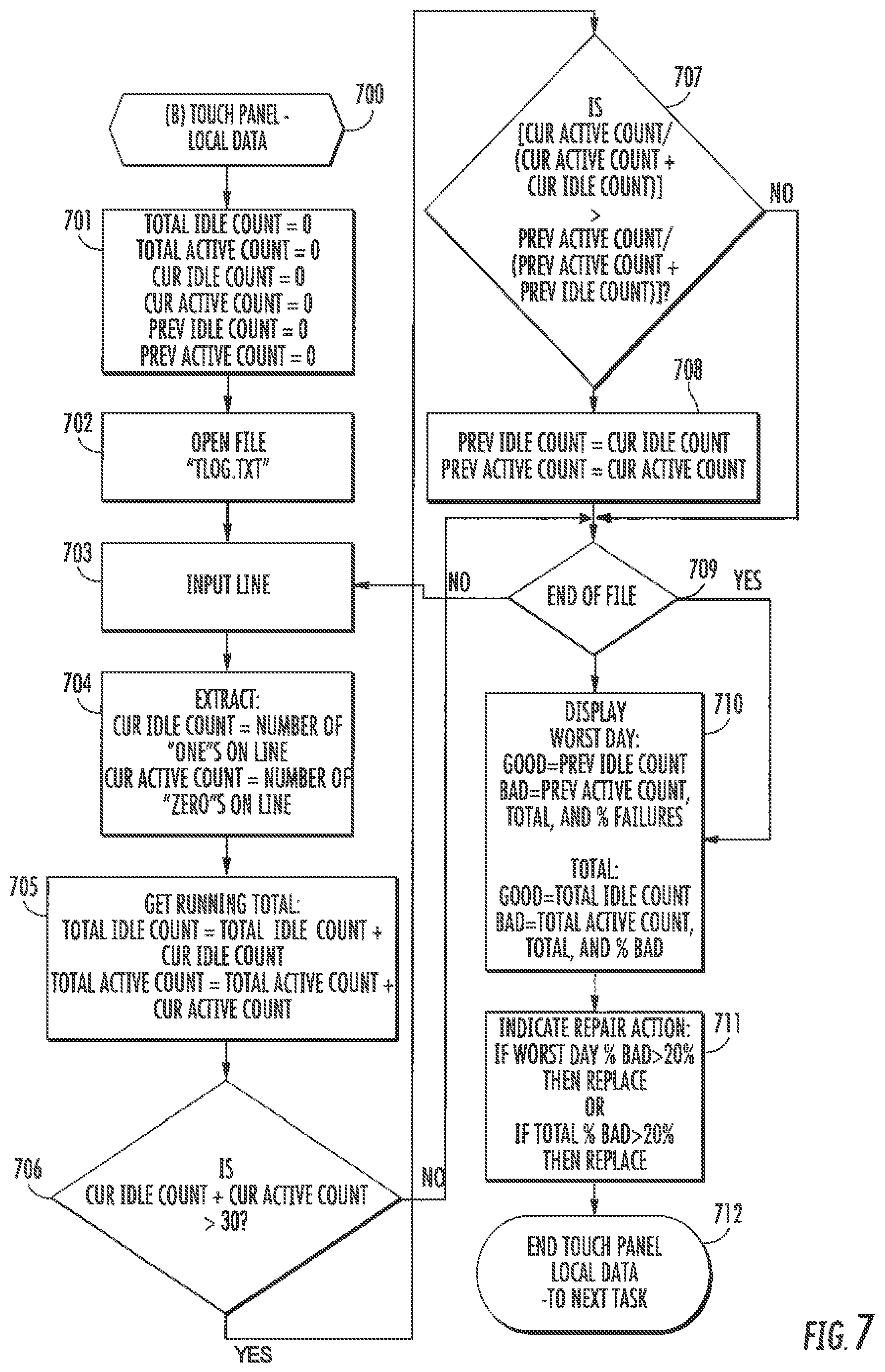
FIG. 7 provides a flowchart of the software utility analyzing the log to determine if the touch panel should be replaced because it is experiencing intermittent failures (step 700). The software utility creates and initializes six variables to zero at step 701: "TotalIdleCount" (i.e., total idle count), "TotalActiveCount" (i.e., total active count), "CurldleCount" (i.e., current idle count), "CurActiveCount" (i.e., current active count), "PrevIdleCount" (i.e., previous idle count), and "PrevActiveCount" (i.e. previous active count). The function of these variables, described further below, is to determine the poorest period of performance of the touch panel, as indicated by the log, and to determine the total number of events logged.
To determine the values for the variables, the software utility parses the log files and increments the variables, reading each line from the log file. Specifically, at step 702, the software utility opens the log file. The software utility then reads a line from the log file at step 703. The number of 0's and 1's on the line are counted. "CurIdleCount" is set equal to the number of 1's and "CurActiveCount" is set equal to the number of 0's counted on the line, respectively, at step 704 (as in, for example, TLOG.txt of FIG. 2). The value of "CurIdleCount" is added to "TotalIdleCount" and the value of "CurActiveCount" is added to "TotalActiveAcount" at step 705.
At step 706, the software utility determines if at least thirty (30) touch panel events have occurred in the given period. If not, the software utility skips to step 709. If yes, the software utility determines if the percentage of bad events on the current period is worse than any previous period by comparing the percentage of "CurActiveCount" to the percentage of "PrevActiveCount" at step 707. If not, the software utility skips to step 709. If yes, the software utility assigns "PrevActiveCount" the same value as "CurActiveCount" and assigns "PrevIdleCount" the same value as "CurIdleCount" at step 708.
At step 709, the software utility determines if it has reached the end of the log. If not, the software utility returns to step 703 and repeats steps 703-709 until the end of the log file is reached. In this manner, the worst performing period of the electronic device will be determined and assigned to the values of "PrevActiveCount" and "PrevIdleCount." Furthermore, "TotalIdleCount" and "TotalActiveAcount" will have a total for all events over all logged time periods for the electronic device as indicated at step 710.
At step 711, the software utility indicates that the touch panel should be replaced under two different conditions. If either condition exists, the touch panel is deemed bad and a repair indication is made to the technician. Under the first condition, the touch panel should be replaced if the worst day percentage of failures exceeds a threshold failure percent, such as twenty percent. This may be represented by the formula ("PrevActiveCount"/("PrevIdleCount"+"PrevActiveCount")).times.100>20.
Under the second condition, the touch panel should be replaced if the total failures percentage exceeds a threshold failure percent, such as twenty percent. This may be represented by the formula ("TotalActiveCount"/("TotalIdleCount"+"TotalActiveCount")).times.100>2- 0. A person having skill in the art will recognize that the threshold failure percentage may be other than twenty percent, and may be calibrated to a percentage that contemplates other factors according to a cost benefit analysis. At step 712, the analysis of the log is complete.
FIGS. 8A and 8B, collectively, provide a flowchart illustrating the process of updating the firmware/software on an electronic device (shown as step 800). At step 801, the outdated files are deleted from the electronic device. At step 802, the new files are copied to the electronic device from a folder previously designated in the required properties window. The copy operation progress and status will be displayed in the activity pane 206.
At step 803, if the electronic device further includes removable storage such as an SD Card, those files will be deleted as well. At step 804, if the electronic device includes a custom firmware package designated in the optional properties window, the software utility will copy the custom firmware from the folder designated at step 805 and unpack it at step 806.
At step 807, if the electronic device includes a battery profile designated in the optional properties window, the software utility will copy the battery profile from the folder designated to the electronic device at step 808. The copy operation progress and status will be displayed in the activity pane 206.
At step 809, if an optional service pack update is designated in the optional properties window, the software utility will copy the service pack update from the folder designated at step 810. The copy operation progress and status will be displayed in the activity pane 206.
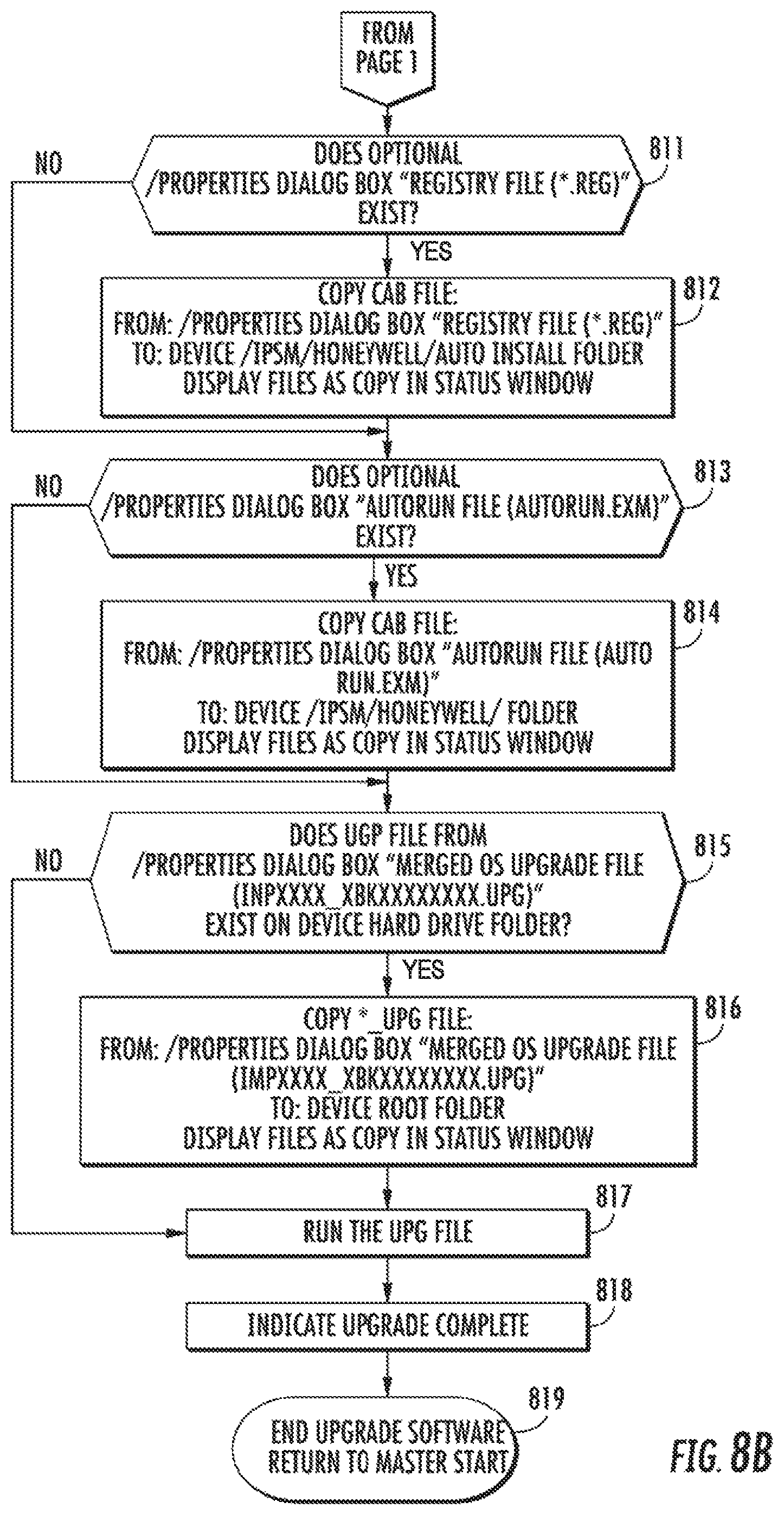
At step 811, if a registry file is designated in the optional properties window, the software utility will copy the registry file from the folder designated at step 812. The copy operation progress and status will be displayed in the activity pane.
At step 813, if an Autorun file is designated in the optional properties window, the software utility will copy the Autorun file from the folder designated at step 814. The copy operation progress and status will be displayed in the activity pane 206.
At step 815, if an upgrade ("UGP") file is designated in the optional properties window, the software utility will copy the UGP file from the folder designated at step 816. The copy operation progress and status will be displayed in the activity pane. At step 817, the UGP file will be run. At step 818, the upgrade status will be displayed in the activity pane 206 as complete. At step 819, the upgrade is complete.
In summary, it can be appreciated from the foregoing description and illustrations that the exemplary systems and methods for identifying bad touch panels in an electronic device facilitates electronic device repairs. By analyzing intermittent failures and determining whether the frequency of failures exceeds certain threshold criteria, a technician can accurately conclude whether to replace the touch panel, thereby minimizing missed repairs and repeat return of failing devices.
To supplement the present disclosure, this application incorporates entirely by reference the following commonly assigned patents, patent application publications, and patent applications: U.S. Pat. Nos. 6,832,725; 7,128,266; U.S. Pat. Nos. 7,159,783; 7,413,127; U.S. Pat. Nos. 7,726,575; 8,294,969; U.S. Pat. Nos. 8,317,105; 8,322,622; U.S. Pat. Nos. 8,366,005; 8,371,507; U.S. Pat. Nos. 8,376,233; 8,381,979; U.S. Pat. Nos. 8,390,909; 8,408,464; U.S. Pat. Nos. 8,408,468; 8,408,469; U.S. Pat. Nos. 8,424,768; 8,448,863; U.S. Pat. Nos. 8,457,013; 8,459,557; U.S. Pat. Nos. 8,469,272; 8,474,712; U.S. Pat. Nos. 8,479,992; 8,490,877; U.S. Pat. Nos. 8,517,271; 8,523,076; U.S. Pat. Nos. 8,528,818; 8,544,737; U.S. Pat. Nos. 8,548,242; 8,548,420; U.S. Pat. Nos. 8,550,335; 8,550,354; U.S. Pat. Nos. 8,550,357; 8,556,174; U.S. Pat. Nos. 8,556,176; 8,556,177; U.S. Pat. Nos. 8,559,767; 8,599,957; U.S. Pat. Nos. 8,561,895; 8,561,903; U.S. Pat. Nos. 8,561,905; 8,565,107; U.S. Pat. Nos. 8,571,307; 8,579,200; U.S. Pat. Nos. 8,583,924; 8,584,945; U.S. Pat. Nos. 8,587,595; 8,587,697; U.S. Pat. Nos. 8,588,869; 8,590,789; U.S. Pat. Nos. 8,596,539; 8,596,542; U.S. Pat. Nos. 8,596,543; 8,599,271; U.S. Pat. Nos. 8,599,957; 8,600,158; U.S. Pat. Nos. 8,600,167; 8,602,309; U.S. Pat. Nos. 8,608,053; 8,608,071; U.S. Pat. Nos. 8,611,309; 8,615,487; U.S. Pat. Nos. 8,616,454; 8,621,123; U.S. Pat. Nos. 8,622,303; 8,628,013; U.S. Pat. Nos. 8,628,015; 8,628,016; U.S. Pat. Nos. 8,629,926; 8,630,491; U.S. Pat. Nos. 8,635,309; 8,636,200; U.S. Pat. Nos. 8,636,212; 8,636,215; U.S. Pat. Nos. 8,636,224; 8,638,806; U.S. Pat. Nos. 8,640,958; 8,640,960; U.S. Pat. Nos. 8,643,717; 8,646,692; U.S. Pat. Nos. 8,646,694; 8,657,200; U.S. Pat. Nos. 8,659,397; 8,668,149; U.S. Pat. Nos. 8,678,285; 8,678,286; U.S. Pat. Nos. 8,682,077; 8,687,282; U.S. Pat. Nos. 8,692,927; 8,695,880; U.S. Pat. Nos. 8,698,949; 8,717,494; U.S. Pat. Nos. 8,717,494; 8,720,783; U.S. Pat. Nos. 8,723,804; 8,723,904; U.S. Pat. Nos. 8,727,223; D702,237; U.S. Pat. Nos. 8,740,082; 8,740,085; U.S. Pat. Nos. 8,746,563; 8,750,445; U.S. Pat. Nos. 8,752,766; 8,756,059; U.S. Pat. Nos. 8,757,495; 8,760,563; U.S. Pat. Nos. 8,763,909; 8,777,108; U.S. Pat. Nos. 8,777,109; 8,779,898; U.S. Pat. Nos. 8,781,520; 8,783,573; U.S. Pat. Nos. 8,789,757; 8,789,758; U.S. Pat. Nos. 8,789,759; 8,794,520; U.S. Pat. Nos. 8,794,522; 8,794,525; U.S. Pat. Nos. 8,794,526; 8,798,367; U.S. Pat. Nos. 8,807,431; 8,807,432; U.S. Pat. Nos. 8,820,630; 8,822,848; U.S. Pat. Nos. 8,824,692; 8,824,696; U.S. Pat. Nos. 8,842,849; 8,844,822; U.S. Pat. Nos. 8,844,823; 8,849,019; U.S. Pat. Nos. 8,851,383; 8,854,633; U.S. Pat. Nos. 8,866,963; 8,868,421; U.S. Pat. Nos. 8,868,519; 8,868,802; U.S. Pat. Nos. 8,868,803; 8,870,074; U.S. Pat. Nos. 8,879,639; 8,880,426; U.S. Pat. Nos. 8,881,983; 8,881,987; U.S. Pat. Nos. 8,903,172; 8,908,995; U.S. Pat. Nos. 8,910,870; 8,910,875; U.S. Pat. Nos. 8,914,290; 8,914,788; U.S. Pat. Nos. 8,915,439; 8,915,444; U.S. Pat. Nos. 8,916,789; 8,918,250; U.S. Pat. Nos. 8,918,564; 8,925,818; U.S. Pat. Nos. 8,939,374; 8,942,480; U.S. Pat. Nos. 8,944,313; 8,944,327; U.S. Pat. Nos. 8,944,332; 8,950,678; U.S. Pat. Nos. 8,967,468; 8,971,346; U.S. Pat. Nos. 8,976,030; 8,976,368; U.S. Pat. Nos. 8,978,981; 8,978,983; U.S. Pat. Nos. 8,978,984; 8,985,456; U.S. Pat. Nos. 8,985,457; 8,985,459; U.S. Pat. Nos. 8,985,461; 8,988,578; U.S. Pat. Nos. 8,988,590; 8,991,704; U.S. Pat. Nos. 8,996,194; 8,996,384; U.S. Pat. Nos. 9,002,641; 9,007,368; U.S. Pat. Nos. 9,010,641; 9,015,513; U.S. Pat. Nos. 9,016,576; 9,022,288; U.S. Pat. Nos. 9,030,964; 9,033,240; U.S. Pat. Nos. 9,033,242; 9,036,054; U.S. Pat. Nos. 9,037,344; 9,038,911; U.S. Pat. Nos. 9,038,915; 9,047,098; U.S. Pat. Nos. 9,047,359; 9,047,420; U.S. Pat. Nos. 9,047,525; 9,047,531; U.S. Pat. Nos. 9,053,055; 9,053,378; U.S. Pat. Nos. 9,053,380; 9,058,526; U.S. Pat. Nos. 9,064,165; 9,064,167; U.S. Pat. Nos. 9,064,168; 9,064,254; U.S. Pat. Nos. 9,066,032; 9,070,032; U.S. Design Pat. No. D716,285; U.S. Design Pat. No. D723,560; U.S. Design Pat. No. D730,357; U.S. Design Pat. No. D730,901; U.S. Design Pat. No. D730,902; U.S. Design Pat. No. D733,112; U.S. Design Pat. No. D734,339; International Publication No. 2013/163789; International Publication No. 2013/173985; International Publication No. 2014/019130; International Publication No. 2014/110495; U.S. Patent Application Publication No. 2008/0185432; U.S. Patent Application Publication No. 2009/0134221; U.S. Patent Application Publication No. 2010/0177080; U.S. Patent Application Publication No. 2010/0177076; U.S. Patent Application Publication No. 2010/0177707; U.S. Patent Application Publication No. 2010/0177749; U.S. Patent Application Publication No. 2010/0265880; U.S. Patent Application Publication No. 2011/0202554; U.S. Patent Application Publication No. 2012/0111946; U.S. Patent Application Publication No. 2012/0168511; U.S. Patent Application Publication No. 2012/0168512; U.S. Patent Application Publication No. 2012/0193423; U.S. Patent Application Publication No. 2012/0203647; U.S. Patent Application Publication No. 2012/0223141; U.S. Patent Application Publication No. 2012/0228382; U.S. Patent Application Publication No. 2012/0248188; U.S. Patent Application Publication No. 2013/0043312; U.S. Patent Application Publication No. 2013/0082104; U.S. Patent Application Publication No. 2013/0175341; U.S. Patent Application Publication No. 2013/0175343; U.S. Patent Application Publication No. 2013/0257744; U.S. Patent Application Publication No. 2013/0257759; U.S. Patent Application Publication No. 2013/0270346; U.S. Patent Application Publication No. 2013/0287258; U.S. Patent Application Publication No. 2013/0292475; U.S. Patent Application Publication No. 2013/0292477; U.S. Patent Application Publication No. 2013/0293539; U.S. Patent Application Publication No. 2013/0293540; U.S. Patent Application Publication No. 2013/0306728; U.S. Patent Application Publication No. 2013/0306731; U.S. Patent Application Publication No. 2013/0307964; U.S. Patent Application Publication No. 2013/0308625; U.S. Patent Application Publication No. 2013/0313324; U.S. Patent Application Publication No. 2013/0313325; U.S. Patent Application Publication No. 2013/0342717; U.S. Patent Application Publication No. 2014/0001267; U.S. Patent Application Publication No. 2014/0008439; U.S. Patent Application Publication No. 2014/0025584; U.S. Patent Application Publication No. 2014/0034734; U.S. Patent Application Publication No. 2014/0036848; U.S. Patent Application Publication No. 2014/0039693; U.S. Patent Application Publication No. 2014/0042814; U.S. Patent Application Publication No. 2014/0049120; U.S. Patent Application Publication No. 2014/0049635; U.S. Patent Application Publication No. 2014/0061306; U.S. Patent Application Publication No. 2014/0063289; U.S. Patent Application Publication No. 2014/0066136; U.S. Patent Application Publication No. 2014/0067692; U.S. Patent Application Publication No. 2014/0070005; U.S. Patent Application Publication No. 2014/0071840; U.S. Patent Application Publication No. 2014/0074746; U.S. Patent Application Publication No. 2014/0076974; U.S. Patent Application Publication No. 2014/0078341; U.S. Patent Application Publication No. 2014/0078345; U.S. Patent Application Publication No. 2014/0097249; U.S. Patent Application Publication No. 2014/0098792; U.S. Patent Application Publication No. 2014/0100813; U.S. Patent Application Publication No. 2014/0103115; U.S. Patent Application Publication No. 2014/0104413; U.S. Patent Application Publication No. 2014/0104414; U.S. Patent Application Publication No. 2014/0104416; U.S. Patent Application Publication No. 2014/0104451; U.S. Patent Application Publication No. 2014/0106594; U.S. Patent Application Publication No. 2014/0106725; U.S. Patent Application Publication No. 2014/0108010; U.S. Patent Application Publication No. 2014/0108402; U.S. Patent Application Publication No. 2014/0110485; U.S. Patent Application Publication No. 2014/0114530; U.S. Patent Application Publication No. 2014/0124577; U.S. Patent Application Publication No. 2014/0124579; U.S. Patent Application Publication No. 2014/0125842; U.S. Patent Application Publication No. 2014/0125853; U.S. Patent Application Publication No. 2014/0125999; U.S. Patent Application Publication No. 2014/0129378; U.S. Patent Application Publication No. 2014/0131438; U.S. Patent Application Publication No. 2014/0131441; U.S. Patent Application Publication No. 2014/0131443; U.S. Patent Application Publication No. 2014/0131444; U.S. Patent Application Publication No. 2014/0131445; U.S. Patent Application Publication No. 2014/0131448; U.S. Patent Application Publication No. 2014/0133379; U.S. Patent Application Publication No. 2014/0136208; U.S. Patent Application Publication No. 2014/0140585; U.S. Patent Application Publication No. 2014/0151453; U.S. Patent Application Publication No. 2014/0152882; U.S. Patent Application Publication No. 2014/0158770; U.S. Patent Application Publication No. 2014/0159869; U.S. Patent Application Publication No. 2014/0166755; U.S. Patent Application Publication No. 2014/0166759; U.S. Patent Application Publication No. 2014/0168787; U.S. Patent Application Publication No. 2014/0175165; U.S. Patent Application Publication No. 2014/0175172; U.S. Patent Application Publication No. 2014/0191644; U.S. Patent Application Publication No. 2014/0191913; U.S. Patent Application Publication No. 2014/0197238; U.S. Patent Application Publication No. 2014/0197239; U.S. Patent Application Publication No. 2014/0197304; U.S. Patent Application Publication No. 2014/0214631; U.S. Patent Application Publication No. 2014/0217166; U.S. Patent Application Publication No. 2014/0217180; U.S. Patent Application Publication No. 2014/0231500; U.S. Patent Application Publication No. 2014/0232930; U.S. Patent Application Publication No. 2014/0247315; U.S. Patent Application Publication No. 2014/0263493; U.S. Patent Application Publication No. 2014/0263645; U.S. Patent Application Publication No. 2014/0267609; U.S. Patent Application Publication No. 2014/0270196; U.S. Patent Application Publication No. 2014/0270229; U.S. Patent Application Publication No. 2014/0278387; U.S. Patent Application Publication No. 2014/0278391; U.S. Patent Application Publication No. 2014/0282210; U.S. Patent Application Publication No. 2014/0284384; U.S. Patent Application Publication No. 2014/0288933; U.S. Patent Application Publication No. 2014/0297058; U.S. Patent Application Publication No. 2014/0299665; U.S. Patent Application Publication No. 2014/0312121; U.S. Patent Application Publication No. 2014/0319220; U.S. Patent Application Publication No. 2014/0319221; U.S. Patent Application Publication No. 2014/0326787; U.S. Patent Application Publication No. 2014/0332590; U.S. Patent Application Publication No. 2014/0344943; U.S. Patent Application Publication No. 2014/0346233; U.S. Patent Application Publication No. 2014/0351317; U.S. Patent Application Publication No. 2014/0353373; U.S. Patent Application Publication No. 2014/0361073; U.S. Patent Application Publication No. 2014/0361082; U.S. Patent Application Publication No. 2014/0362184; U.S. Patent Application Publication No. 2014/0363015; U.S. Patent Application Publication No. 2014/0369511; U.S. Patent Application Publication No. 2014/0374483; U.S. Patent Application Publication No. 2014/0374485; U.S. Patent Application Publication No. 2015/0001301; U.S. Patent Application Publication No. 2015/0001304; U.S. Patent Application Publication No. 2015/0003673; U.S. Patent Application Publication No. 2015/0009338; U.S. Patent Application Publication No. 2015/0009610; U.S. Patent Application Publication No. 2015/0014416; U.S. Patent Application Publication No. 2015/0021397; U.S. Patent Application Publication No. 2015/0028102; U.S. Patent Application Publication No. 2015/0028103; U.S. Patent Application Publication No. 2015/0028104; U.S. Patent Application Publication No. 2015/0029002; U.S. Patent Application Publication No. 2015/0032709; U.S. Patent Application Publication No. 2015/0039309; U.S. Patent Application Publication No. 2015/0039878; U.S. Patent Application Publication No. 2015/0040378; U.S. Patent Application Publication No. 2015/0048168; U.S. Patent Application Publication No. 2015/0049347; U.S. Patent Application Publication No. 2015/0051992; U.S. Patent Application Publication No. 2015/0053766; U.S. Patent Application Publication No. 2015/0053768; U.S. Patent Application Publication No. 2015/0053769; U.S. Patent Application Publication No. 2015/0060544; U.S. Patent Application Publication No. 2015/0062366; U.S. Patent Application Publication No. 2015/0063215; U.S. Patent Application Publication No. 2015/0063676; U.S. Patent Application Publication No. 2015/0069130; U.S. Patent Application Publication No. 2015/0071819; U.S. Patent Application Publication No. 2015/0083800; U.S. Patent Application Publication No. 2015/0086114; U.S. Patent Application Publication No. 2015/0088522; U.S. Patent Application Publication No. 2015/0096872; U.S. Patent Application Publication No. 2015/0099557; U.S. Patent Application Publication No. 2015/0100196; U.S. Patent Application Publication No. 2015/0102109; U.S. Patent Application Publication No. 2015/0115035; U.S. Patent Application Publication No. 2015/0127791; U.S. Patent Application Publication No. 2015/0128116; U.S. Patent Application Publication No. 2015/0129659; U.S. Patent Application Publication No. 2015/0133047; U.S. Patent Application Publication No. 2015/0134470; U.S. Patent Application Publication No. 2015/0136851; U.S. Patent Application Publication No. 2015/0136854; U.S. Patent Application Publication No. 2015/0142492; U.S. Patent Application Publication No. 2015/0144692; U.S. Patent Application Publication No. 2015/0144698; U.S. Patent Application Publication No. 2015/0144701; U.S. Patent Application Publication No. 2015/0149946; U.S. Patent Application Publication No. 2015/0161429; U.S. Patent Application Publication No. 2015/0169925; U.S. Patent Application Publication No. 2015/0169929; U.S. Patent Application Publication No. 2015/0178523; U.S. Patent Application Publication No. 2015/0178534; U.S. Patent Application Publication No. 2015/0178535; U.S. Patent Application Publication No. 2015/0178536; U.S. Patent Application Publication No. 2015/0178537; U.S. Patent Application Publication No. 2015/0181093; U.S. Patent Application Publication No. 2015/0181109; U.S. patent application Ser. No. 13/367,978 for a Laser Scanning Module Employing an Elastomeric U-Hinge Based Laser Scanning Assembly, filed Feb. 7, 2012 (Feng et al.); U.S. patent application Ser. No. 29/458,405 for an Electronic Device, filed Jun. 19, 2013 (Fitch et al.); U.S. patent application Ser. No. 29/459,620 for an Electronic Device Enclosure, filed Jul. 2, 2013 (London et al.); U.S. patent application Ser. No. 29/468,118 for an Electronic Device Case, filed Sep. 26, 2013 (Oberpriller et al.); U.S. patent application Ser. No. 14/150,393 for Indicia-reader Having Unitary Construction Scanner, filed Jan. 8, 2014 (Colavito et al.); U.S. patent application Ser. No. 14/200,405 for Indicia Reader for Size-Limited Applications filed Mar. 7, 2014 (Feng et al.); U.S. patent application Ser. No. 14/231,898 for Hand-Mounted Indicia-Reading Device with Finger Motion Triggering filed Apr. 1, 2014 (Van Horn et al.); U.S. patent application Ser. No. 29/486,759 for an Imaging Terminal, filed Apr. 2, 2014 (Oberpriller et al.); U.S. patent application Ser. No. 14/257,364 for Docking System and Method Using Near Field Communication filed Apr. 21, 2014 (Showering); U.S. patent application Ser. No. 14/264,173 for Autofocus Lens System for Indicia Readers filed Apr. 29, 2014 (Ackley et al.); U.S. patent application Ser. No. 14/277,337 for MULTIPURPOSE OPTICAL READER, filed May 14, 2014 (Jovanovski et al.); U.S. patent application Ser. No. 14/283,282 for TERMINAL HAVING ILLUMINATION AND FOCUS CONTROL filed May 21, 2014 (Liu et al.); U.S. patent application Ser. No. 14/327,827 for a MOBILE-PHONE ADAPTER FOR ELECTRONIC TRANSACTIONS, filed Jul. 10, 2014 (Hejl); U.S. patent application Ser. No. 14/334,934 for a SYSTEM AND METHOD FOR INDICIA VERIFICATION, filed Jul. 18, 2014 (Hejl); U.S. patent application Ser. No. 14/339,708 for LASER SCANNING CODE SYMBOL READING SYSTEM, filed Jul. 24, 2014 (Xian et al.); U.S. patent application Ser. No. 14/340,627 for an AXIALLY REINFORCED FLEXIBLE SCAN ELEMENT, filed Jul. 25, 2014 (Rueblinger et al.); U.S. patent application Ser. No. 14/446,391 for MULTIFUNCTION POINT OF SALE APPARATUS WITH OPTICAL SIGNATURE CAPTURE filed Jul. 30, 2014 (Good et al.); U.S. patent application Ser. No. 14/452,697 for INTERACTIVE INDICIA READER, filed Aug. 6, 2014 (Todeschini); U.S. patent application Ser. No. 14/453,019 for DIMENSIONING SYSTEM WITH GUIDED ALIGNMENT, filed Aug. 6, 2014 (Li et al.); U.S. patent application Ser. No. 14/462,801 for MOBILE COMPUTING DEVICE WITH DATA COGNITION SOFTWARE, filed on Aug. 19, 2014 (Todeschini et al.); U.S. patent application Ser. No. 14/483,056 for VARIABLE DEPTH OF FIELD BARCODE SCANNER filed Sep. 10, 2014 (McCloskey et al.); U.S. patent application Ser. No. 14/513,808 for IDENTIFYING INVENTORY ITEMS IN A STORAGE FACILITY filed Oct. 14, 2014 (Singel et al.); U.S. patent application Ser. No. 14/519,195 for HANDHELD DIMENSIONING SYSTEM WITH FEEDBACK filed Oct. 21, 2014 (Laffargue et al.); U.S. patent application Ser. No. 14/519,179 for DIMENSIONING SYSTEM WITH MULTIPATH INTERFERENCE MITIGATION filed Oct. 21, 2014 (Thuries et al.); U.S. patent application Ser. No. 14/519,211 for SYSTEM AND METHOD FOR DIMENSIONING filed Oct. 21, 2014 (Ackley et al.); U.S. patent application Ser. No. 14/519,233 for HANDHELD DIMENSIONER WITH DATA-QUALITY INDICATION filed Oct. 21, 2014 (Laffargue et al.); U.S. patent application Ser. No. 14/519,249 for HANDHELD DIMENSIONING SYSTEM WITH MEASUREMENT-CONFORMANCE FEEDBACK filed Oct. 21, 2014 (Ackley et al.); U.S. patent application Ser. No.
14/527,191 for METHOD AND SYSTEM FOR RECOGNIZING SPEECH USING WILDCARDS IN AN EXPECTED RESPONSE filed Oct. 29, 2014 (Braho et al.); U.S. patent application Ser. No. 14/529,563 for ADAPTABLE INTERFACE FOR A MOBILE COMPUTING DEVICE filed Oct. 31, 2014 (Schoon et al.); U.S. patent application Ser. No. 14/529,857 for BARCODE READER WITH SECURITY FEATURES filed Oct. 31, 2014 (Todeschini et al.); U.S. patent application Ser. No. 14/398,542 for PORTABLE ELECTRONIC DEVICES HAVING A SEPARATE LOCATION TRIGGER UNIT FOR USE IN CONTROLLING AN APPLICATION UNIT filed Nov. 3, 2014 (Bian et al.); U.S. patent application Ser. No. 14/531,154 for DIRECTING AN INSPECTOR THROUGH AN INSPECTION filed Nov. 3, 2014 (Miller et al.); U.S. patent application Ser. No. 14/533,319 for BARCODE SCANNING SYSTEM USING WEARABLE DEVICE WITH EMBEDDED CAMERA filed Nov. 5, 2014 (Todeschini); U.S. patent application Ser. No. 14/535,764 for CONCATENATED EXPECTED RESPONSES FOR SPEECH RECOGNITION filed Nov. 7, 2014 (Braho et al.); U.S. patent application Ser. No. 14/568,305 for AUTO-CONTRAST VIEWFINDER FOR AN INDICIA READER filed Dec. 12, 2014 (Todeschini); U.S. patent application Ser. No. 14/573,022 for DYNAMIC DIAGNOSTIC INDICATOR GENERATION filed Dec. 17, 2014 (Goldsmith); U.S. patent application Ser. No. 14/578,627 for SAFETY SYSTEM AND METHOD filed Dec. 22, 2014 (Ackley et al.); U.S. patent application Ser. No. 14/580,262 for MEDIA GATE FOR THERMAL TRANSFER PRINTERS filed Dec. 23, 2014 (Bowles); U.S. patent application Ser. No. 14/590,024 for SHELVING AND PACKAGE LOCATING SYSTEMS FOR DELIVERY VEHICLES filed Jan. 6, 2015 (Payne); U.S. patent application Ser. No. 14/596,757 for SYSTEM AND METHOD FOR DETECTING BARCODE PRINTING ERRORS filed Jan. 14, 2015 (Ackley); U.S. patent application Ser. No. 14/416,147 for OPTICAL READING APPARATUS HAVING VARIABLE SETTINGS filed Jan. 21, 2015 (Chen et al.); U.S. patent application Ser. No. 14/614,706 for DEVICE FOR SUPPORTING AN ELECTRONIC TOOL ON A USER'S HAND filed Feb. 5, 2015 (Oberpriller et al.); U.S. patent application Ser. No. 14/614,796 for CARGO APPORTIONMENT TECHNIQUES filed Feb. 5, 2015 (Morton et al.); U.S. patent application Ser. No. 29/516,892 for TABLE COMPUTER filed Feb. 6, 2015 (Bidwell et al.); U.S. patent application Ser. No. 14/619,093 for METHODS FOR TRAINING A SPEECH RECOGNITION SYSTEM filed Feb. 11, 2015 (Pecorari); U.S. patent application Ser. No. 14/628,708 for DEVICE, SYSTEM, AND METHOD FOR DETERMINING THE STATUS OF CHECKOUT LANES filed Feb. 23, 2015 (Todeschini); U.S. patent application Ser. No. 14/630,841 for TERMINAL INCLUDING IMAGING ASSEMBLY filed Feb. 25, 2015 (Gomez et al.); U.S. patent application Ser. No. 14/635,346 for SYSTEM AND METHOD FOR RELIABLE STORE-AND-FORWARD DATA HANDLING BY ENCODED INFORMATION READING TERMINALS filed Mar. 2, 2015 (Sevier); U.S. patent application Ser. No. 29/519,017 for SCANNER filed Mar. 2, 2015 (Zhou et al.); U.S. patent application Ser. No. 14/405,278 for DESIGN PATTERN FOR SECURE STORE filed Mar. 9, 2015 (Zhu et al.); U.S. patent application Ser. No. 14/660,970 for DECODABLE INDICIA READING TERMINAL WITH COMBINED ILLUMINATION filed Mar. 18, 2015 (Kearney et al.); U.S. patent application Ser. No. 14/661,013 for REPROGRAMMING SYSTEM AND METHOD FOR DEVICES INCLUDING PROGRAMMING SYMBOL filed Mar. 18, 2015 (Soule et al.); U.S. patent application Ser. No. 14/662,922 for MULTIFUNCTION POINT OF SALE SYSTEM filed Mar. 19, 2015 (Van Horn et al.); U.S. patent application Ser. No. 14/663,638 for VEHICLE MOUNT COMPUTER WITH CONFIGURABLE IGNITION SWITCH BEHAVIOR filed Mar. 20, 2015 (Davis et al.); U.S. patent application Ser. No. 14/664,063 for METHOD AND APPLICATION FOR SCANNING A BARCODE WITH A SMART DEVICE WHILE CONTINUOUSLY RUNNING AND DISPLAYING AN APPLICATION ON THE SMART DEVICE DISPLAY filed Mar. 20, 2015 (Todeschini); U.S. patent application Ser. No. 14/669,280 for TRANSFORMING COMPONENTS OF A WEB PAGE TO VOICE PROMPTS filed Mar. 26, 2015 (Funyak et al.); U.S. patent application Ser. No. 14/674,329 for AIMER FOR BARCODE SCANNING filed Mar. 31, 2015 (Bidwell); U.S. patent application Ser. No. 14/676,109 for INDICIA READER filed Apr. 1, 2015 (Huck); U.S. patent application Ser. No. 14/676,327 for DEVICE MANAGEMENT PROXY FOR SECURE DEVICES filed Apr. 1, 2015 (Yeakley et al.); U.S. patent application Ser. No. 14/676,898 for NAVIGATION SYSTEM CONFIGURED TO INTEGRATE MOTION SENSING DEVICE INPUTS filed Apr. 2, 2015 (Showering); U.S. patent application Ser. No. 14/679,275 for DIMENSIONING SYSTEM CALIBRATION SYSTEMS AND METHODS filed Apr. 6, 2015 (Laffargue et al.); U.S. patent application Ser. No. 29/523,098 for HANDLE FOR A TABLET COMPUTER filed Apr. 7, 2015 (Bidwell et al.); U.S. patent application Ser. No. 14/682,615 for SYSTEM AND METHOD FOR POWER MANAGEMENT OF MOBILE DEVICES filed Apr. 9, 2015 (Murawski et al.); U.S. patent application Ser. No. 14/686,822 for MULTIPLE PLATFORM SUPPORT SYSTEM AND METHOD filed Apr. 15, 2015 (Qu et al.); U.S. patent application Ser. No. 14/687,289 for SYSTEM FOR COMMUNICATION VIA A PERIPHERAL HUB filed Apr. 15, 2015 (Kohtz et al.); U.S. patent application Ser. No. 29/524,186 for SCANNER filed Apr. 17, 2015 (Zhou et al.); U.S. patent application Ser. No. 14/695,364 for MEDICATION MANAGEMENT SYSTEM filed Apr. 24, 2015 (Sewell et al.); U.S. patent application Ser. No. 14/695,923 for SECURE UNATTENDED NETWORK AUTHENTICATION filed Apr. 24, 2015 (Kubler et al.); U.S. patent application Ser. No. 29/525,068 for TABLET COMPUTER WITH REMOVABLE SCANNING DEVICE filed Apr. 27, 2015 (Schulte et al.); U.S. patent application Ser. No. 14/699,436 for SYMBOL READING SYSTEM HAVING PREDICTIVE DIAGNOSTICS filed Apr. 29, 2015 (Nahill et al.); U.S. patent application Ser. No. 14/702,110 for SYSTEM AND METHOD FOR REGULATING BARCODE DATA INJECTION INTO A RUNNING APPLICATION ON A SMART DEVICE filed May 1, 2015 (Todeschini et al.); U.S. patent application Ser. No. 14/702,979 for TRACKING BATTERY CONDITIONS filed May 4, 2015 (Young et al.); U.S. patent application Ser. No. 14/704,050 for INTERMEDIATE LINEAR POSITIONING filed May 5, 2015 (Charpentier et al.); U.S. patent application Ser. No. 14/705,012 for HANDS-FREE HUMAN MACHINE INTERFACE RESPONSIVE TO A DRIVER OF A VEHICLE filed May 6, 2015 (Fitch et al.); U.S. patent application Ser. No. 14/705,407 for METHOD AND SYSTEM TO PROTECT SOFTWARE-BASED NETWORK-CONNECTED DEVICES FROM ADVANCED PERSISTENT THREAT filed May 6, 2015 (Hussey et al.); U.S. patent application Ser. No. 14/707,037 for SYSTEM AND METHOD FOR DISPLAY OF INFORMATION USING A VEHICLE-MOUNT COMPUTER filed May 8, 2015 (Chamberlin); U.S. patent application Ser. No. 14/707,123 for APPLICATION INDEPENDENT DEX/UCS INTERFACE filed May 8, 2015 (Pape); U.S. patent application Ser. No. 14/707,492 for METHOD AND APPARATUS FOR READING OPTICAL INDICIA USING A PLURALITY OF DATA SOURCES filed May 8, 2015 (Smith et al.); U.S. patent application Ser. No. 14/710,666 for PRE-PAID USAGE SYSTEM FOR ENCODED INFORMATION READING TERMINALS filed May 13, 2015 (Smith); U.S. patent application Ser. No. 29/526,918 for CHARGING BASE filed May 14, 2015 (Fitch et al.); U.S. patent application Ser. No. 14/715,672 for AUGUMENTED REALITY ENABLED HAZARD DISPLAY filed May 19, 2015 (Venkatesha et al.); U.S. patent application Ser. No. 14/715,916 for EVALUATING IMAGE VALUES filed May 19, 2015 (Ackley); U.S. patent application Ser. No. 14/722,608 for INTERACTIVE USER INTERFACE FOR CAPTURING A DOCUMENT IN AN IMAGE SIGNAL filed May 27, 2015 (Showering et al.); U.S. patent application Ser. No. 29/528,165 for IN-COUNTER BARCODE SCANNER filed May 27, 2015 (Oberpriller et al.); U.S. patent application Ser. No. 14/724,134 for ELECTRONIC DEVICE WITH WIRELESS PATH SELECTION CAPABILITY filed May 28, 2015 (Wang et al.); U.S. patent application Ser. No. 14/724,849 for METHOD OF PROGRAMMING THE DEFAULT CABLE INTERFACE SOFTWARE IN AN INDICIA READING DEVICE filed May 29, 2015 (Barten); U.S. patent application Ser. No. 14/724,908 for IMAGING APPARATUS HAVING IMAGING ASSEMBLY filed May 29, 2015 (Barber et al.); U.S. patent application Ser. No. 14/725,352 for APPARATUS AND METHODS FOR MONITORING ONE OR MORE PORTABLE DATA TERMINALS (Caballero et al.); U.S. patent application Ser. No. 29/528,590 for ELECTRONIC DEVICE filed May 29, 2015 (Fitch et al.); U.S. patent application Ser. No. 29/528,890 for MOBILE COMPUTER HOUSING filed Jun. 2, 2015 (Fitch et al.); U.S. patent application Ser. No. 14/728,397 for DEVICE MANAGEMENT USING VIRTUAL INTERFACES CROSS-REFERENCE TO RELATED APPLICATIONS filed Jun. 2, 2015 (Caballero); U.S. patent application Ser. No. 14/732,870 for DATA COLLECTION MODULE AND SYSTEM filed Jun. 8, 2015 (Powilleit); U.S. patent application Ser. No. 29/529,441 for INDICIA READING DEVICE filed Jun. 8, 2015 (Zhou et al.); U.S. patent application Ser. No. 14/735,717 for INDICIA-READING SYSTEMS HAVING AN INTERFACE WITH A USER'S NERVOUS SYSTEM filed Jun. 10, 2015 (Todeschini); U.S. patent application Ser. No. 14/738,038 for METHOD OF AND SYSTEM FOR DETECTING OBJECT WEIGHING INTERFERENCES filed Jun. 12, 2015 (Amundsen et al.); U.S. patent application Ser. No. 14/740,320 for TACTILE SWITCH FOR A MOBILE ELECTRONIC DEVICE filed Jun. 16, 2015 (Bandringa); U.S. patent application Ser. No. 14/740,373 for CALIBRATING A VOLUME DIMENSIONER filed Jun. 16, 2015 (Ackley et al.); U.S. patent application Ser. No. 14/742,818 for INDICIA READING SYSTEM EMPLOYING DIGITAL GAIN CONTROL filed Jun. 18, 2015 (Xian et al.); U.S. patent application Ser. No. 14/743,257 for WIRELESS MESH POINT PORTABLE DATA TERMINAL filed Jun. 18, 2015 (Wang et al.); U.S. patent application Ser. No. 29/530,600 for CYCLONE filed Jun. 18, 2015 (Vargo et al); U.S. patent application Ser. No. 14/744,633 for IMAGING APPARATUS COMPRISING IMAGE SENSOR ARRAY HAVING SHARED GLOBAL SHUTTER CIRCUITRY filed Jun. 19, 2015 (Wang); U.S. patent application Ser. No. 14/744,836 for CLOUD-BASED SYSTEM FOR READING OF DECODABLE INDICIA filed Jun. 19, 2015 (Todeschini et al.); U.S. patent application Ser. No. 14/745,006 for SELECTIVE OUTPUT OF DECODED MESSAGE DATA filed Jun. 19, 2015 (Todeschini et al.); U.S. patent application Ser. No. 14/747,197 for OPTICAL PATTERN PROJECTOR filed Jun. 23, 2015 (Thuries et al.); U.S. patent application Ser. No. 14/747,490 for DUAL-PROJECTOR THREE-DIMENSIONAL SCANNER filed Jun. 23, 2015 (Jovanovski et al.); and U.S. patent application Ser. No. 14/748,446 for CORDLESS INDICIA READER WITH A MULTIFUNCTION COIL FOR WIRELESS CHARGING AND EAS DEACTIVATION, filed Jun. 24, 2015 (Xie et al.).
In the specification and/or figures, typical embodiments and environments of the invention have been disclosed. The present invention is not limited to such exemplary embodiments. The use of the term "and/or" includes any and all combinations of one or more of the associated listed items. The figures are schematic representations and so are not necessarily drawn to scale. Unless otherwise noted, specific terms have been used in a generic and descriptive sense and not for purposes of limitation.
* * * * *
D00000
D00001
D00002
D00003
D00004
D00005
D00006
D00007
D00008
D00009
D00010
XML
uspto.report is an independent third-party trademark research tool that is not affiliated, endorsed, or sponsored by the United States Patent and Trademark Office (USPTO) or any other governmental organization. The information provided by uspto.report is based on publicly available data at the time of writing and is intended for informational purposes only.
While we strive to provide accurate and up-to-date information, we do not guarantee the accuracy, completeness, reliability, or suitability of the information displayed on this site. The use of this site is at your own risk. Any reliance you place on such information is therefore strictly at your own risk.
All official trademark data, including owner information, should be verified by visiting the official USPTO website at www.uspto.gov. This site is not intended to replace professional legal advice and should not be used as a substitute for consulting with a legal professional who is knowledgeable about trademark law.