Methods and materials for metamaterials exhibiting form-induced birefringence
Hofmann , et al. February 9, 2
U.S. patent number 10,914,866 [Application Number 16/038,004] was granted by the patent office on 2021-02-09 for methods and materials for metamaterials exhibiting form-induced birefringence. This patent grant is currently assigned to HARRIS CORPORATION GCS, J.A. WOOLLAM CO. INC., UNIVERSITY OF NORTH CAROLINA CHARLOTTE. The grantee listed for this patent is Harris Corporation GCS, J.A. Woollam Co. Inc., University of North Carolina Charlotte. Invention is credited to Daniel Fullager, Craig M. Herzinger, Tino Hofmann, Susanne Madeline Lee, Stefan Schoeche, Erin Kathleen Sharma.


View All Diagrams
| United States Patent | 10,914,866 |
| Hofmann , et al. | February 9, 2021 |
Methods and materials for metamaterials exhibiting form-induced birefringence
Abstract
Materials comprising metamaterials exhibiting form-induced birefringence and anisotropic optical properties are provided. The disclosed articles comprise structures with critical dimensions which are on the order of or smaller than the wavelength for the gigahertz and terahertz spectral range. Methods of preparing same using stereolithography are disclosed. In a further aspect, the disclosed methods pertain to spectroscopic ellipsometry methods comprising a biaxial (orthorhombic) layer homogenization approach is to analyze the terahertz ellipsometric data obtained at three different sample azimuth orientations. The disclosed articles and methods demonstrate provide an avenue to fabricate metamaterials for the terahertz spectral range and allows tailoring of the polarizability and anisotropy of the host material. This abstract is intended as a scanning tool for purposes of searching in the particular art and is not intended to be limiting of the present invention.
| Inventors: | Hofmann; Tino (Harrisburg, NC), Fullager; Daniel (Charlotte, NC), Schoeche; Stefan (Lincoln, NE), Herzinger; Craig M. (Lincoln, NE), Lee; Susanne Madeline (Cocoa, FL), Sharma; Erin Kathleen (Palm Bay, FL) | ||||||||||
|---|---|---|---|---|---|---|---|---|---|---|---|
| Applicant: |
|
||||||||||
| Assignee: | HARRIS CORPORATION GCS (Palm
Bay, FL) UNIVERSITY OF NORTH CAROLINA CHARLOTTE (Charlotte, NC) J.A. WOOLLAM CO. INC. (Lincoln, NE) |
||||||||||
| Family ID: | 1000003526766 | ||||||||||
| Appl. No.: | 16/038,004 | ||||||||||
| Filed: | July 17, 2018 |
Related U.S. Patent Documents
| Application Number | Filing Date | Patent Number | Issue Date | ||
|---|---|---|---|---|---|
| 62533472 | Jul 17, 2017 | ||||
| Current U.S. Class: | 1/1 |
| Current CPC Class: | G02B 1/04 (20130101); B29C 64/135 (20170801); G02B 1/002 (20130101); B33Y 80/00 (20141201); B29K 2033/12 (20130101); B33Y 70/00 (20141201); B29K 2033/08 (20130101); Y10T 428/26 (20150115); B29L 2011/00 (20130101); B29K 2995/0032 (20130101); B33Y 10/00 (20141201) |
| Current International Class: | B29C 64/135 (20170101); B33Y 80/00 (20150101); B33Y 70/00 (20200101); B33Y 10/00 (20150101); G02B 1/00 (20060101); G02B 1/04 (20060101) |
| Field of Search: | ;428/141-155 |
References Cited [Referenced By]
U.S. Patent Documents
| 9007688 | April 2015 | Vasylyev |
| 2016/0025288 | January 2016 | Vasylyev |
Other References
|
Shelby et al., Experimental Verication of a Negative Index of RefractionScience 292, 77 (2001). cited by applicant . Pendry et al., Phys., Reversing Light: Negative Refraction, Today 57, 37 (2004). cited by applicant . Mao et al., The Emerging Frontiers and Applications of High-Resolution 3D Printing, Micromachines 8, 113 (2017). cited by applicant . Kawata et al., Finer features for functional microdevices, Nature 412, 697 (2001). cited by applicant . Farsari et al., Two-photon Fabrication, Nat. Photonics 3, 450 (2009). cited by applicant . Zheng et al., Design and optimization of a light-emitting diode projection micro-stereolithography three-dimensional manufacturing systemSpadaccini, Rev. Sci. Instrum. 83, 125001 (2012). cited by applicant . Boltasseva et al., Fabrication of optical negative-index metamaterials: Recent advances and outlook, Metamaterials 2, 1 (2008). cited by applicant . Thiel et al., Dip-in depletion optical lithography of three-dimensional chiral polarizers, Opt. Lett. 38, 4252 (2013). cited by applicant . Otter et al., Hybrid 3-D-Printing Technology for Tunable THz Applications, Proc. IEEE 105, 756 (2017). cited by applicant . Zhang et al., Investigation on 3-D-Printing Technologies for Millimeter-Wave and Terahertz Applications, Proc. IEEE 105, 723 (2017). cited by applicant . Hofmann et al., Variable-wavelength frequency-domain terahertz ellipsometry, Rev. Sci. Instrum. 81, 023101 (2010). cited by applicant . Hofmann et al., THz dielectric anisotropy of metal slanted columnar thin films, Appl. Phys. Lett. 99, 081903 (2011). cited by applicant . Kuhne et al., Invited Article: An integrated mid-infrared, far-infrared, and terahertz optical Hall effect Instrument, Rev. Sci. Instrum. 85, 071301 (2014). cited by applicant . Hofmann et al., Screening effects in metal sculptured thin films studied with terahertz Mueller matrix ellipsometry, Applied Surface Science 421, 513-517 (2017). cited by applicant . Fujiwara, Spectroscopic Ellipsometry (John Wiley & Sons, New York, 2007). cited by applicant . Hauge, Recent Developments in Instrumentation in Ellipsometry, Surf. Sci. 96, 108 (1980). cited by applicant . Jellison et al., Spectroscopic ellipsometry data analysis: measured versus calculated quantities, Thin Solid Films 313-314, 33 (1998). cited by applicant . Naftaly et al., Terahertz Time-Domain Spectroscopy for Material Characterization, Proc. IEEE 95, 1658 (2007). cited by applicant . Schmidt et al., Generalized ellipsometry for monoclinic absorbing materials: determination of optical constants of Cr columnar thin filmsOpt. Lett. 34, 992 (2009). cited by applicant. |
Primary Examiner: Sample; David
Assistant Examiner: Flores, Jr.; Donald M
Attorney, Agent or Firm: Thomas | Horstemeyer, LLP
Government Interests
STATEMENT REGARDING FEDERALLY SPONSORED RESEARCH OR DEVELOPMENT
This invention was made with U.S. Government support under grant number 1068050, awarded by the National Science Foundation. The U.S. government has certain rights in the invention.
Parent Case Text
CROSS-REFERENCE TO RELATED APPLICATIONS
This Application claims the benefit of U.S. Provisional Application No. 62/533,472, filed on Jul. 17, 2017, which is incorporated herein by reference in its entirety.
Claims
That which is claimed is:
1. An article comprising a plurality of individual structures, wherein the article has a y-axis, an x-axis, and a z-axis, wherein each individual structure comprises a polymer optically transparent in the gigahertz and/or terahertz spectral range, and has an elongation axis, wherein each individual structure has an aspect ratio of a length in the longest dimension along the elongation axis to the longest dimension of the cross-sectional geometry of about 0.1:1 to about 3000:1; wherein the plurality of structures is slanted relative to the x-axis and has a first slanting angle of about 1.degree. to 89.degree. and a second slanting angle of about 1.degree. to 89.degree.; wherein the first slanting angle .theta. is an angle between the elongation axis of each individual structure of plurality of the structures and the z-axis; wherein the second slanting angle .phi. is an angle between the elongation axis of each individual structure of plurality of the structures and the y-axis; wherein the x-axis, the y-axis, and the z-axis are perpendicular to one another; and wherein the polymer is a polyacrylate.
2. The article of claim 1, wherein the polyacrylate is a photosensitive polymer.
3. The article of claim 1, wherein the polyacrylate is methacrylate, 1,6-hexanediol diacrylate, poly(ethylene glycol) diacrylate, or poly(ethylene glycol) dimethacrylate.
4. The article of claim 1, wherein the plurality of structures is arranged on a substrate material, and wherein the substrate material is co-planar with the x-axis and the y-axis.
5. The article of claim 4, wherein the substrate material comprises a polyacrylate.
6. The article of claim 1, wherein the structure has a cross-sectional geometry dimension of about 1 .mu.m to about 1000 .mu.m.
7. The article of claim 1, wherein the structure has a length dimension of about 100 .mu.m to about 3000 .mu.m.
8. The article of claim 1, wherein the article exhibits form-induced birefringence or optical anisotropy.
9. A device comprising the article of claim 1.
10. An article comprising a layer having a plurality of spatially coherent individual columnar structures, wherein the article has a y-axis, an x-axis, and a z-axis; wherein the plurality of spatially coherent individual columnar structures comprises individual columnar structures each individual columnar structure comprises a polymer optically transparent in the gigahertz and/or terahertz spectral range, and has an elongation axis, wherein each individual columnar structure has an aspect ratio of a length in the longest dimension along the elongation axis to the longest dimension of the cross-sectional geometry of about 0.1:1 to about 3000:1, and wherein each of the individual columnar structures has a cross-sectional geometry that is irregular shape, ellipsoid, circular, or a regular geometric figure having 5-12 sides; a first slanting angle of about 1.degree. to 89.degree.; and a second slanting angle of about 1.degree. to 89.degree.; wherein the first slanting angle .theta. is an angle between the plurality of structures and the z-axis and the second slanting angle .phi. is an angle between the plurality of structures and the y-axis; wherein the y-axis and the z-axis are perpendicular to one another.
11. The article of claim 10, wherein the individual columnar structures are spatially arranged within the plurality of structures to form a geometric pattern.
12. The article of claim 10, wherein the individual columnar structures are arranged to have a gap between adjacent individual structures.
13. The article of claim 12, wherein the gap is such that each of the individual columnar structures is separated from a nearest individual structure by 10-100 .mu.m.
14. The article of claim 10, wherein the individual columnar structures touch one another.
15. The article of claim 10, wherein the individual columnar structures are arranged on a substrate, wherein the substrate is co-planar with the x-axis and the y-axis, and the z-axis is normal to the substrate.
16. The article of claim 15, wherein the substrate is in contact with the individual columnar structures and fixes them in a desired arrangement to one another.
17. The article of claim 15, wherein the substrate has a thickness of about 100 .mu.m to about 5000 .mu.m.
18. The article of claim 10, wherein each of the individual columnar structures has a cross-sectional geometry that is circular.
Description
BACKGROUND
Metamaterials have attracted continued interest for almost two decades due to their unique electromagnetic properties, which can differ substantially from their constituents and often do not even exist in naturally occurring materials (R. A. Shelby, D. R. Smith, and S. Schultz, Science 292, 77 (2001); and J. B. Pendry and D. R. Smith, Phys. Today 57, 37 (2004)). Commonly, lithographic fabrication approaches (e.g. optical, electron-beam, femtosecond laser, or nanoimprint lithography) are employed for the syntheses of metamaterials which are composed of building blocks with subwavelength feature sizes (M. Mao, J. He, X. Li, B. Zhang, Q. Lei, Y. Liu, and D. Li, Micromachines 8, 113 (2017)). Lithographic techniques, however, typically require expensive equipment, complicated processing steps, long production period and only allow the fabrication of two-dimensional (2D) or 2.5D structures on a flat surface, which fundamentally limits the classes of metamaterials which can be fabricated with these approaches (M. Mao, J. He, X. Li, B. Zhang, Q. Lei, Y. Liu, and D. Li, Micromachines 8, 113 (2017)).
More recently two-photon polymerization and micro-stereolithography have been used to fabricate complex three-dimensional (3D) architectures with micro and nanoscale resolutions, respectively (S. Kawata, H.-B. Sun, T. Tanaka, and K. Takada, Nature 412, 697 (2001); M. Farsari and B. N. Chichkov, Nat. Photonics 3, 450 (2009); and X. Zheng, J. Deotte, M. P. Alonso, G. R. Farquar, T. H. Weisgraber, S. Gemberling, H. Lee, N. Fang, and C. M. Spadaccini, Rev. Sci. Instrum. 83, 125001 (2012)). These layer-by-layer additive fabrication techniques are ideally suited for the synthesis of metamaterials with virtually arbitrary 3D architectures designed to operate in the infrared and visible spectral range (A. Boltasseva and V. M. Shalaev, Metamaterials 2, 1 (2008); and M. Thiel, J. Ott, A. Radke, J. Kaschke, and M. Wegener, Opt. Lett. 38, 4252 (2013)). Although, stereolithography has been used to fabricate waveguide components, phase shifters, and band pass filters for the spectral range from 10 GHz to 1 THz (W. J. Otter and S. Lucyszyn, Proc. IEEE 105, 756 (2017); and B. Zhang, Y.-X. Guo, H. Zirath, and Y. P. Zhang, Proc. IEEE 105, 723 (2017)), thus far it has not been amenable to the manufacture of metamaterials with pre-designed anisotropic or other optical properties.
Despite interest materials exhibiting optical anisotropy at gigahertz and/or terahertz frequencies methods which do not depend upon wave guides have been lacking, as have methods for the rapid manufacture of same. In particular, metamaterials which exhibit optical anisotropy or form-induced birefringence at gigahertz and/or terahertz frequencies have not been available. and approaches for accurate experimental measurement and analysis of the anisotropic optical properties have not been reported so far. These needs and others are addressed in the present disclosure.
SUMMARY
In accordance with the purpose(s) of the present disclosure, as embodied and broadly described herein, the disclosure, in one aspect, relates to the design, fabrication, and use of 3D metamaterials which exhibit form-induced birefringence and are composed of structures with critical dimensions which are on the order of or smaller than the wavelength for the GHz and THz spectral range. In a further aspect, the disclosure pertains to ensembles of micrometer-sized structures composed of dielectric materials exhibit a strong optical anisotropy in the GHz and THz spectral range.
In an aspect, the disclosed metamaterials exhibit optical anisotropy provided by coupling between spatially coherent arrangements of millimeter, micrometer, or sub-micrometer-sized structures and depends on the geometry, spacing, spatial order and material of the constituents. In a further aspect, the dielectric properties of the constituents may be either optically isotropic or anisotropic in nature.
In an aspect, the metamaterial comprises an acrylate polymer. In a still further aspect, the metamaterial comprises spatially coherent structures. In a yet further aspect, the spatially coherent structures are arranged upon a support substrate. In a further aspect, the spatially coherent structures are arranged at an angle relative to the support substrate.
In an aspect, the spatially coherent dielectric structures disclosed herein exhibit optically anisotropic properties in the gigahertz and terahertz spectral range while the bulk properties of the dielectric constituents can be isotropic.
In an aspect, the present disclosure pertains to methods of making the disclosed metamaterials. In a further aspect, the method comprises a maskless photolithographic technique. In a still further aspect, the maskless photolithographic technique is stereolithography or 3D two photon lithography. In a still further aspect, the stereolithography comprises providing an acrylate polymer.
Other systems, methods, features, and advantages of the present disclosure will be or become apparent to one with skill in the art upon examination of the following drawings and detailed description. It is intended that all such additional systems, methods, features, and advantages be included within this description, be within the scope of the present disclosure, and be protected by the accompanying claims. In addition, all optional and preferred features and modifications of the described embodiments are usable in all aspects of the disclosure taught herein. Furthermore, the individual features of the dependent claims, as well as all optional and preferred features and modifications of the described embodiments are combinable and interchangeable with one another.
BRIEF DESCRIPTION OF THE DRAWINGS
Many aspects of the present disclosure can be better understood with reference to the following drawings. The components in the drawings are not necessarily to scale, emphasis instead being placed upon clearly illustrating the principles of the present disclosure. Moreover, in the drawings, like reference numerals designate corresponding parts throughout the several views.
FIG. 1 shows representative data of form-induced birefringence effects in a representative material comprising slanted wires with a diameter of 200 .mu.m, a length of approximately 1400 .mu.m, and a slanting angle of 45.degree..
FIG. 2 shows representative spectroscopic ellipsometric data of a representative material of the present disclosure showing a terahertz transparent response.
FIG. 3 shows representative real (.epsilon..sub.i) and imaginary (.epsilon..sub.2) portions of the complex isotropic dielectric function of a disclosed article in the terahertz and infrared spectral range.
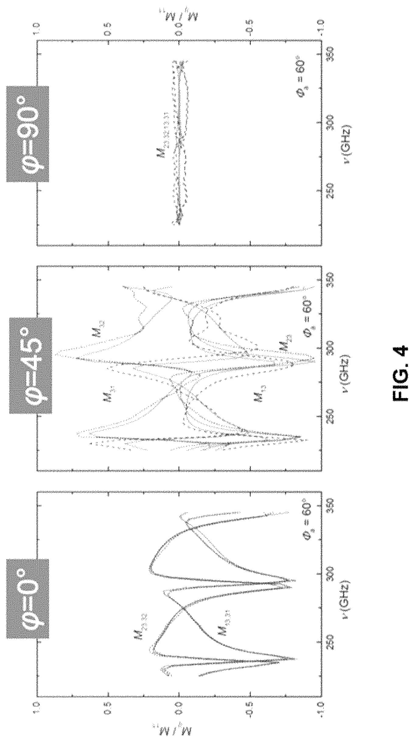
FIG. 4 shows representative experimental data compared to model calculated results for block-off diagonal Mueller matrix elements for a disclosed representative material.
FIG. 5 shows representative experimental data compared to model calculated results for block-on diagonal Mueller matrix elements for a disclosed representative material.
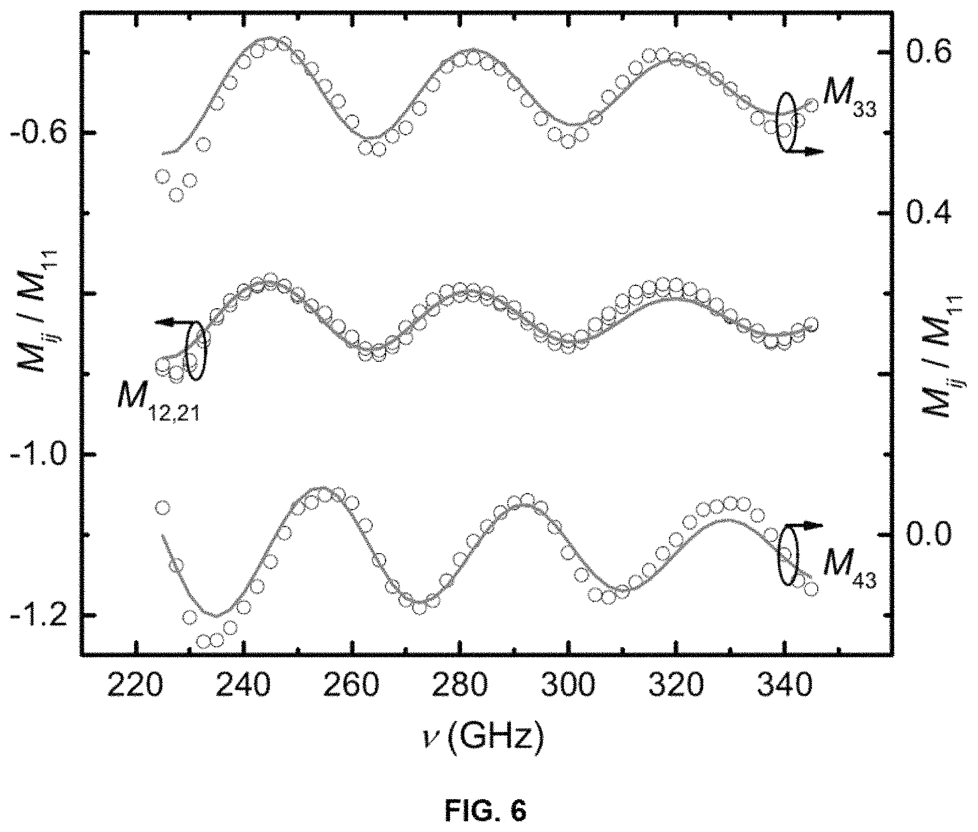
FIG. 6 shows representative experimental (symbols) and best-model calculated (solid lines) Mueller matrix spectra of an isotropic reference substrate.
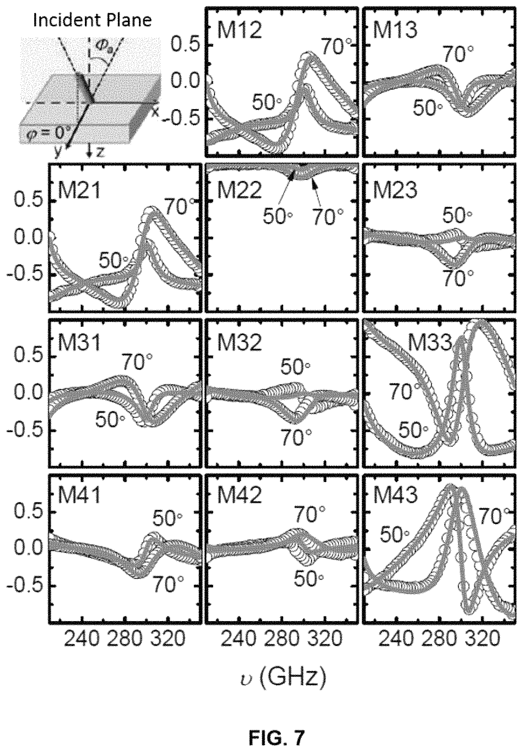
FIG. 7 shows representative experimental (symbols) and best-model calculated (solid lines) Mueller matrix spectra of a representative material for three different in-plane orientations, .phi.=0.degree. and two angles of incidence .phi..sub.a=50.degree. and 70.degree.. The inset illustrates orientation of the slanting plane with respect to the plane of incidence.
FIG. 8 shows representative experimental (symbols) and best-model calculated (solid lines) Mueller matrix spectra of a representative material for three different in-plane orientations, .phi.=45.degree. and two angles of incidence .phi..sub.a=50.degree. and 70.degree.. The inset illustrates orientation of the slanting plane with respect to the plane of incidence.
FIG. 9 shows representative experimental (symbols) and best-model calculated (solid lines) Mueller matrix spectra of a representative material for three different in-plane orientations, .phi.=90.degree. and two angles of incidence .PHI..sub.a=50.degree. and 70.degree.. The inset illustrates orientation of the slanting plane with respect to the plane of incidence.
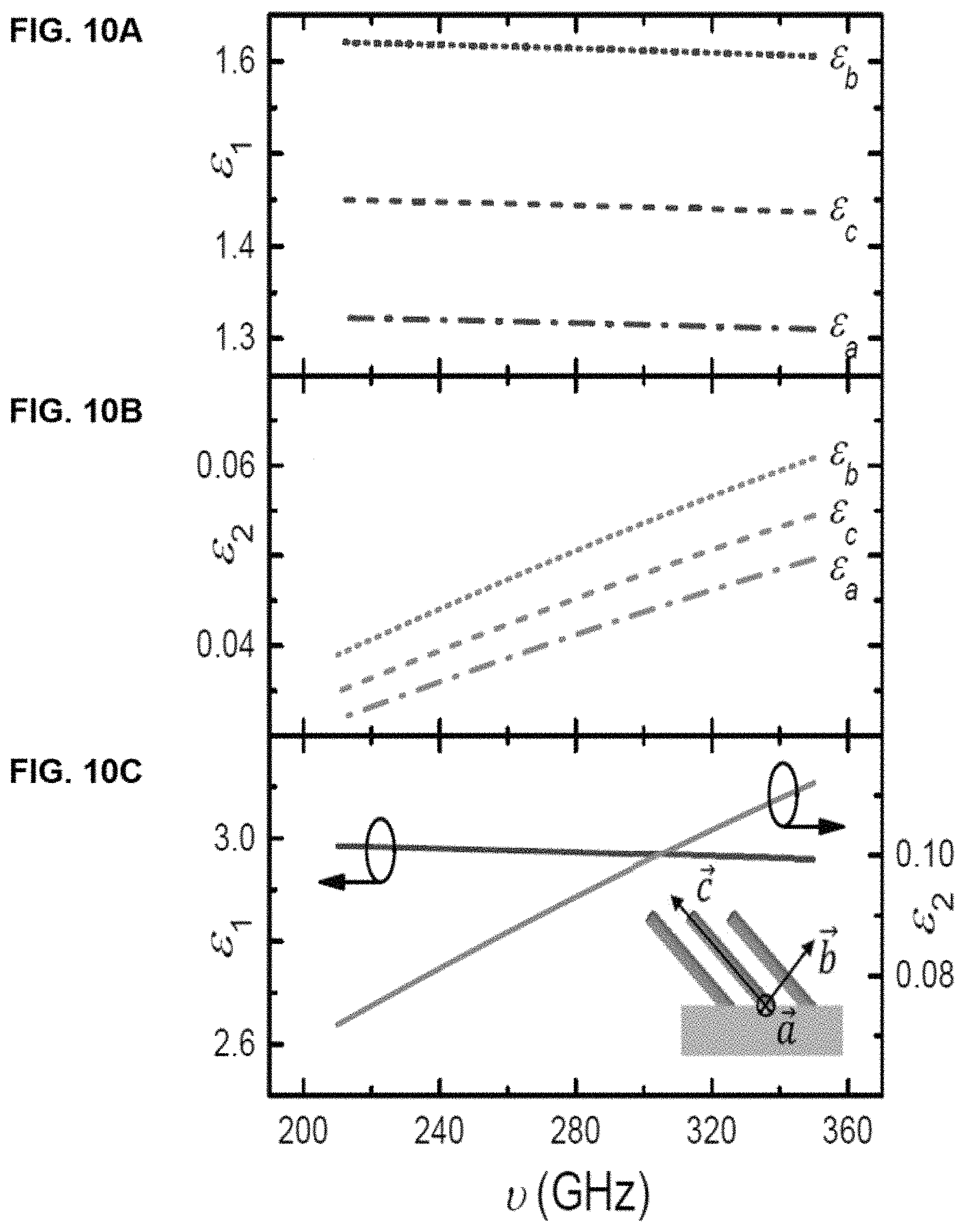
FIGS. 10A-10C show representative data pertaining to the real and imaginary part of the biaxial (orthorhombic, see inset in FIG. 100) dielectric function .epsilon..sub.a, .epsilon..sub.b, .epsilon..sub.c obtained from the best-model calculation for the methacrylate slanted columnar layer are shown in FIG. 10A and FIG. 10B, respectively. The isotropic dielectric function for the bulk-like methacrylate obtained from the reference substrate is shown for comparison in FIG. 100.
FIG. 11 shows an aspect of a schematic of disclosed article 1 comprising a plurality of structures 20 comprising individual structures 10 that may extend generally in a first direction 12, wherein the plurality of structures are arranged on a substrate 30. Each individual structure can be characterized by a length dimension 40 and a cross-sectional geometry dimension 41.
FIG. 12 shows angular relationships among elements of a disclosed article 1 comprising a plurality of structures 20 comprising individual structures 10, wherein the plurality of structures are arranged on a substrate 30. In the figure, angle .theta. is an angle describing the angular relationship of an individual structural element from the z-axis (a first slanting angle). Angles .phi. and .PHI..sub.a is describe the sample azimuth and angle of incidence for the spectroscopic ellipsometry measurement. A second slanting angle can be used to describe the angle an individual structural element from the y-axis.
Additional advantages of the invention will be set forth in part in the description which follows, and in part will be obvious from the description, or can be learned by practice of the invention. The advantages of the invention will be realized and attained by means of the elements and combinations particularly pointed out in the appended claims. It is to be understood that both the foregoing general description and the following detailed description are exemplary and explanatory only and are not restrictive of the invention, as claimed.
DETAILED DESCRIPTION
The disclosures herein will be described more fully hereinafter with reference to the accompanying drawings, in which some, but not all possible embodiments are shown. Indeed, disclosures may be embodied in many different forms and should not be construed as limited to the embodiments set forth herein; rather, these embodiments are provided so that this disclosure will satisfy applicable legal requirements. Like numbers refer to like elements throughout.
Many modifications and other embodiments disclosed herein will come to mind to one skilled in the art to which the disclosed compositions and methods pertain having the benefit of the teachings presented in the foregoing descriptions and the associated drawings. Therefore, it is to be understood that the disclosures are not to be limited to the specific embodiments disclosed and that modifications and other embodiments are intended to be included within the scope of the appended claims. Although specific terms are employed herein, they are used in a generic and descriptive sense only and not for purposes of limitation.
It is also to be understood that the terminology used herein is for the purpose of describing particular aspects only and is not intended to be limiting. As used in the specification and in the claims, the term "comprising" can include the aspect of "consisting of." Unless defined otherwise, all technical and scientific terms used herein have the same meaning as commonly understood by one of ordinary skill in the art to which the disclosed compositions and methods belong. In this specification and in the claims which follow, reference will be made to a number of terms which shall be defined herein.
As will be apparent to those of skill in the art upon reading this disclosure, each of the individual embodiments described and illustrated herein has discrete components and features which may be readily separated from or combined with the features of any of the other several embodiments without departing from the scope or spirit of the present disclosure. Any recited method can be carried out in the order of events recited or in any other order that is logically possible.
All publications mentioned herein are incorporated herein by reference to disclose and describe the methods and/or materials in connection with which the publications are cited. The publications discussed herein are provided solely for their disclosure prior to the filing date of the present application. Nothing herein is to be construed as an admission that the present invention is not entitled to antedate such publication by virtue of prior invention. Further, the dates of publication provided herein can be different from the actual publication dates, which can require independent confirmation.
Prior to describing the various embodiments, the following definitions are provided and should be used unless otherwise indicated.
Unless defined otherwise, all technical and scientific terms used herein have the same meaning as commonly understood by one of ordinary skill in the art to which this disclosure belongs. It will be further understood that terms, such as those defined in commonly used dictionaries, should be interpreted as having a meaning that is consistent with their meaning in the context of the specification and relevant art and should not be interpreted in an idealized or overly formal sense unless expressly defined herein.
As used herein, nomenclature for compounds, including organic compounds, can be given using common names, IUPAC, IUBMB, or CAS recommendations for nomenclature. When one or more stereochemical features are present, Cahn-Ingold-Prelog rules for stereochemistry can be employed to designate stereochemical priority, E/Z specification, and the like. One of skill in the art can readily ascertain the structure of a compound if given a name, either by systemic reduction of the compound structure using naming conventions, or by commercially available software, such as CHEMDRAW.TM. (Cambridgesoft Corporation, U.S.A.).
As used herein, "comprising" is to be interpreted as specifying the presence of the stated features, integers, steps, or components as referred to, but does not preclude the presence or addition of one or more features, integers, steps, or components, or groups thereof. Additionally, the term "comprising" is intended to include examples encompassed by the terms "consisting essentially of" and "consisting of." Similarly, the term "consisting essentially of" is intended to include examples encompassed by the term "consisting of."
As used in the specification and the appended claims, the singular forms "a," "an" and "the" include plural referents unless the context clearly dictates otherwise. Thus, for example, reference to "a structure," "a polyacrylate polymer," or "a substrate," including, but not limited to, any of two or more such structures, polyacrylate polymers, or substrates, and the like.
Reference to "a" chemical compound or polymer refers one or more molecules of the chemical compound or polymer, rather than being limited to a single molecule of the chemical compound. Furthermore, the one or more molecules may or may not be identical, so long as they fall under the category of the chemical compound. Thus, for example, "a" polyacrylate is interpreted to include one or more polymer molecules of the polyacrylate, where the polymer molecules may or may not be identical (e.g., different molecular weights and/or isomers).
It should be noted that ratios, concentrations, amounts, and other numerical data can be expressed herein in a range format. Where the stated range includes one or both of the limits, ranges excluding either or both of those included limits are also included in the disclosure, e.g. the phrase "x to y" includes the range from `x` to `y` as well as the range greater than `x` and less than `y`. The range can also be expressed as an upper limit, e.g. `about x, y, z, or less` and should be interpreted to include the specific ranges of `about x`, `about y`, and `about z` as well as the ranges of `less than x`, less than y', and `less than z`. Likewise, the phrase `about x, y, z, or greater` should be interpreted to include the specific ranges of `about x`, `about y`, and `about z` as well as the ranges of `greater than x`, greater than y', and `greater than z`. In addition, the phrase "about `x` to `y`", where `x` and `y` are numerical values, includes "about `x` to about `y`". It is to be understood that such a range format is used for convenience and brevity, and thus, should be interpreted in a flexible manner to include not only the numerical values explicitly recited as the limits of the range, but also to include all the individual numerical values or sub-ranges encompassed within that range as if each numerical value and sub-range is explicitly recited. To illustrate, a numerical range of "about 0.1% to 5%" should be interpreted to include not only the explicitly recited values of about 0.1% to about 5%, but also include individual values (e.g., 1%, 2%, 3%, and 4%) and the sub-ranges (e.g., 0.5%, 1.1%, 2.4%, 3.2%, and 4.4%) within the indicated range.
As used herein, the terms "about," "approximate," "at or about," and "substantially" mean that the amount or value in question can be the exact value or a value that provides equivalent results or effects as recited in the claims or taught herein. That is, it is understood that amounts, sizes, formulations, parameters, and other quantities and characteristics are not and need not be exact, but may be approximate and/or larger or smaller, as desired, reflecting tolerances, conversion factors, rounding off, measurement error and the like, and other factors known to those of skill in the art such that equivalent results or effects are obtained. In some circumstances, the value that provides equivalent results or effects cannot be reasonably determined. In such cases, it is generally understood, as used herein, that "about" and "at or about" mean the nominal value indicated .+-.10% variation unless otherwise indicated or inferred. In general, an amount, size, formulation, parameter or other quantity or characteristic is "about," "approximate," or "at or about" whether or not expressly stated to be such. It is understood that where "about," "approximate," or "at or about" is used before a quantitative value, the parameter also includes the specific quantitative value itself, unless specifically stated otherwise.
As used herein, the term "effective amount" refers to an amount that is sufficient to achieve the desired modification of a physical property of the composition or material. For example, an "effective amount" of a polymer refers to an amount that is sufficient to achieve the desired improvement in the property modulated by the formulation component, e.g., achieving the desired level of optical or birefringence properties. The specific level in terms of wt % in a composition required as an effective amount will depend upon a variety of factors including the amount and type of polyacrylate, amount and type of fillers, amount and type of second polymers, and end use of the article made using the composition.
As used herein, the term "effective angle" refers to an angle that is sufficient to achieve the desired modification of a physical property of the composition or material, e.g., dielectric optical anisotropy in the gigahertz and/or terahertz frequency range or form-induced birefringence. For example, an "effective angle" of a structure refers to an angle that is sufficient to achieve the desired improvement in the property modulated by the structure, e.g., dielectric optical anisotropy in the gigahertz and/or terahertz frequency range or form-induced birefringence. The specific level in terms of angle relative to an axis of the material required as an effective angle will depend upon a variety of factors including the amount and type of polymer, desired response frequency, geometry of the structure, and packing arrangement of the individual structures within the plurality of structures.
As used herein, the terms "optional" or "optionally" means that the subsequently described event or circumstance can or cannot occur, and that the description includes instances where said event or circumstance occurs and instances where it does not.
As used herein, the term "units" can be used to refer to individual (co)monomer units such that, for example, styrenic repeat units refers to individual styrene (co)monomer units in the polymer. In addition, the term "units" can be used to refer to polymeric block units such that, for example, "styrene repeating units" can also refer to polystyrene blocks; "units of polyethylene" refers to block units of polyethylene; "units of polypropylene" refers to block units of polypropylene; "units of polybutylene" refers to block units of polybutylene, and so on. Such use will be clear from the context.
The term "copolymer" refers to a polymer having two or more monomer species, and includes terpolymers (i.e., copolymers having three monomer species).
Unless otherwise specified, temperatures referred to herein are based on atmospheric pressure (i.e. one atmosphere).
Disclosed are the components to be used to prepare the articles of the invention as well as the materials to be used within the methods disclosed herein. These and other materials are disclosed herein, and it is understood that when combinations, subsets, interactions, groups, etc. of these materials are disclosed that while specific reference of each various individual and collective combinations and permutation of these compounds cannot be explicitly disclosed, each is specifically contemplated and described herein. For example, if a particular compound is disclosed and discussed and a number of modifications that can be made to a number of molecules including the compounds are discussed, specifically contemplated is each and every combination and permutation of the compound and the modifications that are possible unless specifically indicated to the contrary. Thus, if a class of molecules A, B, and C are disclosed as well as a class of molecules D, E, and F and an example of a combination molecule, A-D is disclosed, then even if each is not individually recited each is individually and collectively contemplated meaning combinations, A-E, A-F, B-D, B-E, B-F, C-D, C-E, and C-F are considered disclosed. Likewise, any subset or combination of these is also disclosed. Thus, for example, the sub-group of A-E, B-F, and C-E would be considered disclosed. This concept applies to all aspects of this application including, but not limited to, steps in methods of making and using the compositions of the invention. Thus, if there are a variety of additional steps that can be performed it is understood that each of these additional steps can be performed with any specific aspect or combination of aspects of the methods of the invention.
References in the specification and concluding claims to parts by weight of a particular element or component in a composition or article, denotes the weight relationship between the element or component and any other elements or components in the composition or article for which a part by weight is expressed. Thus, in a compound containing 2 parts by weight of component X and 5 parts by weight component Y, X and Y are present at a weight ratio of 2:5, and are present in such ratio regardless of whether additional components are contained in the compound.
As used herein the terms "weight percent," "wt %," and "wt. %," which can be used interchangeably, indicate the percent by weight of a given component based on the total weight of the composition, unless otherwise specified. That is, unless otherwise specified, all wt % values are based on the total weight of the composition. It should be understood that the sum of wt % values for all components in a disclosed composition or formulation are equal to 100.
In an aspect, the present disclosure pertains to the design, fabrication, and use of 3D metamaterials which exhibit form-induced birefringence and are composed of structures with critical dimensions which are on the order of or smaller than the wavelength for the gigahertz (GHz) and terahertz (THz) spectral frequency range.
In an aspect, the present disclosure pertains to an article comprising a plurality of micrometer-sized individual structures composed of dielectric materials, assembled with a spacing and geometry such that the article exhibits a strong optical anisotropy in the gigahertz and terahertz spectral range. Without wishing to be bound by a particular theory, the optical anisotropy is believed to be caused by coupling between spatially coherent arrangements of millimeter, micrometer, or sub-micrometer-sized structures, also referred to herein as individual structures. The optical anisotropy of the article depends, at least in part, on the geometry, spacing, spatial order and material of the individual structures. In other words, one can modify the optical anisotropy of the article by changing the geometry, spacing, spatial order, and/or material of the individual structures. The dielectric properties of each of the individual structures may be either optically isotropic or anisotropic in nature. Data are provided herein below verifying that a disclosed 3D metamaterial comprising 3D slanted wire structures comprising from methacrylate is associated with the desired optical properties. Moreover, the data provided herein below demonstrate that form-induced birefringence can be accurately measured and characterized using generalized ellipsometry in the gigahertz and terahertz spectral range.
In an aspect, the present disclosure pertains to 3D metamaterials comprising spatially coherent dielectric structures exhibiting optically anisotropic properties in the gigahertz and terahertz spectral range while the bulk properties of the dielectric constituents can be isotropic. Without wishing to be bound by a particular theory, it is believed that the origin of the birefringence derives from the interaction between the subwavelength structures arranged in a spatially coherent fashion and an electromagnetic wave. Further, without wishing to be bound by a particular theory, it is believed that slanted wires for which the bases are arranged in a square unit-cell the optical response is found to be biaxial as demonstrated in the data described herein below.
Referring to FIGS. 11 and 12, in an aspect, the disclosed article 1, a 3D metamaterial, comprises a plurality of structures 20 comprising individual structures 10, each individual structure 10 may extend generally in a first direction 12. The plurality of structures may be arranged on an optional substrate 30. In a further aspect, the substrate 30 is present in the disclosed article. In a further aspect, the substrate 30 is not present in the disclosed article. The plurality of structures 20 can be arranged in a certain spatial and packing arrangement to one another, as described further herein. In a still further aspect, the plurality of structures 20 may be arranged such that one or more adjacent individual structures 10 touch one another as shown in FIGS. 11 and 12. Each individual structure 10 can be characterized by a length dimension 40 and a cross-sectional geometry dimension 41. That is, the length dimension is a dimension extending from an edge in contact with the optional substrate 30 along the first direction 12 to the opposing end of the individual structure 10. The cross-sectional geometry dimension 41 is the cross-sectional geometry dimension of an individual structure 10. As shown in FIG. 11, the cross-sectional geometry is circular, and accordingly the longest cross-sectional geometry dimension is the diameter thereof. Alternatively, the cross-sectional geometry could be an ellipse, and in such an instance, the cross-sectional geometry dimension would be a length of a major axis of such an ellipse shape. Further aspects of the cross-sectional geometry are disclosed herein below.
In various aspects, the substrate 30 can have a variety of configurations provided that: (a) the substrate 30 is in communication or contact with the plurality of structures 20 and fixes them in a desired arrangement to one another; and (b) the support structure 30 is not of a symmetry which, in combination with the plurality of structures 20, results in an isotropic arrangement of components. For example, the substrate 30 can be formed from a continuous sheet of material essentially solid in geometry. Alternatively, the substrate 30 can be a mesh-like structure in which the strands or wires of the mesh structure are in communication or contact with the plurality of structures 20 and thereby fixing them in a desired arrangement to one another. As noted above, particularly if the substrate 30 is not a solid sheet, e.g., if a mesh with strands or wirings and an open mesh-like structure, it should be configured in a manner such that support structure is not of a symmetry which, in combination with the wires, results in an isotropic arrangement of components. That is, the substrate 30 in communication or contact with the plurality of structures 20 provides for optical anisotropy and not optical isotropy.
In various aspects, the individual structure 10 can be characterized by an aspect ratio that is a ratio of a length dimension 40 to a cross-sectional geometry dimension 41 such that the aspect ratio has a value of about 0.1:1 to about 3000:1; about 0.2:1 to about 3000:1; about 0.3:1 to about 3000:1; about 0.4:1 to about 3000:1; about 0.5:1 to about 3000:1; about 0.6:1 to about 3000:1; about 0.7:1 to about 3000:1; about 0.8:1 to about 3000:1; about 0.9:1 to about 3000:1; about 1:1 to about 3000:1; 1.1:1 to about 3000:1; about 1.2:1 to about 3000:1; about 1.3:1 to about 3000:1; about 1.4:1 to about 3000:1; about 1.5:1 to about 3000:1; about 1.6:1 to about 3000:1; about 1.7:1 to about 3000:1; about 1.8:1 to about 3000:1; about 1.9:1 to about 3000:1; about 2:1 to about 3000:1; about 3:1 to about 3000:1; about 4:1 to about 3000:1; about 5:1 to about 3000:1; about 6:1 to about 3000:1; about 7:1 to about 3000:1; about 8:1 to about 3000:1; about 9:1 to about 3000:1; about 10:1 to about 3000:1; about 100:1 to about 3000:1; about 200:1 to about 3000:1; about 300:1 to about 3000:1; about 400:1 to about 3000:1; about 500:1 to about 3000:1; about 600:1 to about 3000:1; about 700:1 to about 3000:1; about 800:1 to about 3000:1; about 900:1 to about 3000:1; about 1000:1 to about 3000:1; about 1100:1 to about 3000:1; about 1200:1 to about 3000:1; about 1300:1 to about 3000:1; about 1400:1 to about 3000:1; about 1500:1 to about 3000:1; about 1600:1 to about 3000:1; about 1700:1 to about 3000:1; about 1800:1 to about 3000:1; about 1900:1 to about 3000:1; about 2000:1 to about 3000:1; about 2100:1 to about 3000:1; about 2200:1 to about 3000:1; about 2300:1 to about 3000:1; about 2400:1 to about 3000:1; about 2500:1 to about 3000:1; about 2600:1 to about 3000:1; about 2700:1 to about 3000:1; about 2800:1 to about 3000:1; about 2900:1 to about 3000:1; any value or combination of values within the foregoing ranges, or any sub-range within the foregoing ranges.
In a further aspect, the individual structure 10 can be characterized by an aspect ratio that is a ratio of a length dimension 40 to a cross-sectional geometry dimension 41 such that the aspect ratio has a value of about 0.1:1 to about 2000:1; about 0.2:1 to about 2000:1; about 0.3:1 to about 2000:1; about 0.4:1 to about 2000:1; about 0.5:1 to about 2000:1; about 0.6:1 to about 2000:1; about 0.7:1 to about 2000:1; about 0.8:1 to about 2000:1; about 0.9:1 to about 2000:1; about 1:1 to about 2000:1; 1.1:1 to about 2000:1; about 1.2:1 to about 2000:1; about 1.3:1 to about 2000:1; about 1.4:1 to about 2000:1; about 1.5:1 to about 2000:1; about 1.6:1 to about 2000:1; about 1.7:1 to about 2000:1; about 1.8:1 to about 2000:1; about 1.9:1 to about 2000:1; about 2:1 to about 2000:1; about 3:1 to about 2000:1; about 4:1 to about 2000:1; about 5:1 to about 2000:1; about 6:1 to about 2000:1; about 7:1 to about 2000:1; about 8:1 to about 2000:1; about 9:1 to about 2000:1; about 10:1 to about 2000:1; about 100:1 to about 2000:1; about 200:1 to about 2000:1; about 300:1 to about 2000:1; about 400:1 to about 2000:1; about 500:1 to about 2000:1; about 600:1 to about 2000:1; about 700:1 to about 2000:1; about 800:1 to about 2000:1; about 900:1 to about 2000:1; about 1000:1 to about 2000:1; about 1100:1 to about 2000:1; about 1200:1 to about 2000:1; about 1300:1 to about 2000:1; about 1400:1 to about 2000:1; about 1500:1 to about 2000:1; about 1600:1 to about 2000:1; about 1700:1 to about 2000:1; about 1800:1 to about 2000:1; about 1900:1 to about 2000:1; any value or combination of values within the foregoing ranges, or any sub-range within the foregoing ranges.
In a further aspect, the individual structure 10 can be characterized by an aspect ratio that is a ratio of a length dimension 40 to a cross-sectional geometry dimension 41 such that the aspect ratio has a value of about 0.1:1 to about 1000:1; about 0.2:1 to about 1000:1; about 0.3:1 to about 1000:1; about 0.4:1 to about 1000:1; about 0.5:1 to about 1000:1; about 0.6:1 to about 1000:1; about 0.7:1 to about 1000:1; about 0.8:1 to about 1000:1; about 0.9:1 to about 1000:1; about 1:1 to about 1000:1; 1.1:1 to about 1000:1; about 1.2:1 to about 1000:1; about 1.3:1 to about 1000:1; about 1.4:1 to about 1000:1; about 1.5:1 to about 1000:1; about 1.6:1 to about 1000:1; about 1.7:1 to about 1000:1; about 1.8:1 to about 1000:1; about 1.9:1 to about 1000:1; about 2:1 to about 1000:1; about 3:1 to about 1000:1; about 4:1 to about 1000:1; about 5:1 to about 1000:1; about 6:1 to about 1000:1; about 7:1 to about 1000:1; about 8:1 to about 1000:1; about 9:1 to about 1000:1; about 10:1 to about 1000:1; about 100:1 to about 1000:1; about 200:1 to about 1000:1; about 300:1 to about 1000:1; about 400:1 to about 1000:1; about 500:1 to about 1000:1; about 600:1 to about 1000:1; about 700:1 to about 1000:1; about 800:1 to about 1000:1; about 900:1 to about 1000:1; any value or combination of values within the foregoing ranges, or any sub-range within the foregoing ranges.
In a further aspect, the individual structure 10 can be characterized by an aspect ratio that is a ratio of a length dimension 40 to a cross-sectional geometry dimension 41 such that the aspect ratio has a value of about 0.1:1 to about 750:1; about 0.2:1 to about 750:1; about 0.3:1 to about 750:1; about 0.4:1 to about 750:1; about 0.5:1 to about 750:1; about 0.6:1 to about 750:1; about 0.7:1 to about 750:1; about 0.8:1 to about 750:1; about 0.9:1 to about 750:1; about 1:1 to about 750:1; 1.1:1 to about 750:1; about 1.2:1 to about 750:1; about 1.3:1 to about 750:1; about 1.4:1 to about 750:1; about 1.5:1 to about 750:1; about 1.6:1 to about 750:1; about 1.7:1 to about 750:1; about 1.8:1 to about 750:1; about 1.9:1 to about 750:1; about 2:1 to about 750:1; about 3:1 to about 750:1; about 4:1 to about 750:1; about 5:1 to about 750:1; about 6:1 to about 750:1; about 7:1 to about 750:1; about 8:1 to about 750:1; about 9:1 to about 750:1; about 10:1 to about 750:1; about 100:1 to about 750:1; about 200:1 to about 750:1; about 300:1 to about 750:1; about 400:1 to about 750:1; about 500:1 to about 750:1; about 600:1 to about 750:1; about 700:1 to about 750:1; any value or combination of values within the foregoing ranges, or any sub-range within the foregoing ranges.
In a further aspect, the individual structure 10 can be characterized by an aspect ratio that is a ratio of a length dimension 40 to a cross-sectional geometry dimension 41 such that the aspect ratio has a value of about 0.1:1 to about 500:1; about 0.2:1 to about 500:1; about 0.3:1 to about 500:1; about 0.4:1 to about 500:1; about 0.5:1 to about 500:1; about 0.6:1 to about 500:1; about 0.7:1 to about 500:1; about 0.8:1 to about 500:1; about 0.9:1 to about 500:1; about 1:1 to about 500:1; 1.1:1 to about 500:1; about 1.2:1 to about 500:1; about 1.3:1 to about 500:1; about 1.4:1 to about 500:1; about 1.5:1 to about 500:1; about 1.6:1 to about 500:1; about 1.7:1 to about 500:1; about 1.8:1 to about 500:1; about 1.9:1 to about 500:1; about 2:1 to about 500:1; about 3:1 to about 500:1; about 4:1 to about 500:1; about 5:1 to about 500:1; about 6:1 to about 500:1; about 7:1 to about 500:1; about 8:1 to about 500:1; about 9:1 to about 500:1; about 10:1 to about 500:1; about 100:1 to about 500:1; about 200:1 to about 500:1; about 300:1 to about 500:1; about 400:1 to about 500:1; any value or combination of values within the foregoing ranges, or any sub-range within the foregoing ranges.
Referring still to FIGS. 11 and 12, in an aspect, the article 1 may comprise two or more layers such that each layer comprises a plurality of structures 20 comprising individual structures 10, each individual structure 10 may extend generally in a first direction 12. In a further aspect, the layers comprising the plurality of structures 20 are arranged on an optional substrate 30 as shown schematically in FIGS. 11 and 12.
In various aspects, the substrate 30 has a thickness of about 100 .mu.m to about 5000 .mu.m, or any combination of values within the foregoing range. In a further aspect, the substrate 30 has a thickness of about 100 .mu.m, about 150 .mu.m, about 200 .mu.m, about 250 .mu.m, about 300 .mu.m, about 350 .mu.m, about 400 .mu.m, about 450 .mu.m, about 500 .mu.m, about 550 .mu.m, about 600 .mu.m, about 650 .mu.m, about 700 .mu.m, about 750 .mu.m, about 800 .mu.m, about 850 .mu.m, about 900 .mu.m, about 950 .mu.m, about 1000 .mu.m, about 1050 .mu.m, 1100 .mu.m, about 1150 .mu.m, about 1200 .mu.m, about 1250 .mu.m, about 1300 .mu.m, about 1350 .mu.m, about 1400 .mu.m, about 1450 .mu.m, about 1500 .mu.m, about 1550 .mu.m, about 1600 .mu.m, about 1650 .mu.m, about 1700 .mu.m, about 1750 .mu.m, about 1800 .mu.m, about 1850 .mu.m, about 1900 .mu.m, about 1950 .mu.m, about 2000 .mu.m, about 2050 .mu.m, 2100 .mu.m, about 2150 .mu.m, about 2200 .mu.m, about 2250 .mu.m, about 2300 .mu.m, about 2350 .mu.m, about 2400 .mu.m, about 2450 .mu.m, about 2500 .mu.m, about 2550 .mu.m, about 2600 .mu.m, about 2650 .mu.m, about 2700 .mu.m, about 2750 .mu.m, about 2800 .mu.m, about 2850 .mu.m, about 2900 .mu.m, about 2950 .mu.m, about 3000 .mu.m, about 3050 .mu.m, 3100 .mu.m, about 3150 .mu.m, about 3200 .mu.m, about 3250 .mu.m, about 3300 .mu.m, about 3350 .mu.m, about 3400 .mu.m, about 3450 .mu.m, about 3500 .mu.m, about 3550 .mu.m, about 3600 .mu.m, about 3650 .mu.m, about 3700 .mu.m, about 3750 .mu.m, about 3800 .mu.m, about 3850 .mu.m, about 3900 .mu.m, about 3950 .mu.m, about 4000 .mu.m, about 4050 .mu.m, 4100 .mu.m, about 4150 .mu.m, about 4200 .mu.m, about 4250 .mu.m, about 4300 .mu.m, about 4350 .mu.m, about 4400 .mu.m, about 4450 .mu.m, about 4500 .mu.m, about 4550 .mu.m, about 4600 .mu.m, about 4650 .mu.m, about 4700 .mu.m, about 4750 .mu.m, about 4800 .mu.m, about 4850 .mu.m, about 4900 .mu.m, about 4950 .mu.m, about 5000 .mu.m, any combination of the foregoing values, or any range utilizing the foregoing values as an lower and upper bound for the range. In a still further aspect, the substrate 30 is isotropic in the gigahertz and/or terahertz spectral range. In a yet further aspect, the substrate 30 comprises a polymer. In a yet further aspect, the substrate 30 comprises a polyacrylate polymer, or copolymer thereof. The substrate 30 comprises a polymer can comprise a polymer such as one of those disclosed by Saiki, et al. in U.S. Pat. No. 4,789,620, and such polymers are incorporated herein by referenced.
In an aspect, the substrate 30 comprises a polymer comprising methacrylate, 1,6-hexanediol diacrylate (HDDA), poly(ethylene glycol) diacrylate (PEGDA), poly(ethylene glycol) dimethacrylate, 1,4-butanediol diacrylate, 1,4-dutanediol dimethacrylate, 1,6-hexamethylene glycol diacrylate, 1,6-hexamethylene glycol dimethacrylate, neopentyl glycol diacrylate, neopentyl glycol dimethacrylate, trimethylolpropane triacrylate, trimethylolpropane trimethacrylate, pentaerythritol triacrylate, pentaerythritol trimethacrylate, pentaerythritol tetraacrylate, pentaerythritol tetramethacrylate, dipentaerythritol hexaacrylate, dipentaerythritol hexamethacrylate, triethylene glycol diacrylate, triethylene glycol dimethacrylate, urethane acrylate, or urethane methacrylate.
In an aspect, the substrate 30 comprises a copolymer comprising methacrylate, 1,6-hexanediol diacrylate (HDDA), poly(ethylene glycol) diacrylate (PEGDA), poly(ethylene glycol) dimethacrylate, 1,4-butanediol diacrylate, 1,4-dutanediol dimethacrylate, 1,6-hexamethylene glycol diacrylate, 1,6-hexamethylene glycol dimethacrylate, neopentyl glycol diacrylate, neopentyl glycol dimethacrylate, trimethylolpropane triacrylate, trimethylolpropane trimethacrylate, pentaerythritol triacrylate, pentaerythritol trimethacrylate, pentaerythritol tetraacrylate, pentaerythritol tetramethacrylate, dipentaerythritol hexaacrylate, dipentaerythritol hexamethacrylate, triethylene glycol diacrylate, triethylene glycol dimethacrylate, urethane acrylate, or urethane methacrylate.
In various aspects, one or more of the individual structures 10, comprises a polymer that is optically transparent in the gigahertz and/or terahertz spectral range. In a further aspect, one or more of the individual structures 10 comprises a photosensitive polymer. In a still further aspect, one or more of the individual structures 10 comprise a polyacrylate polymer, or copolymer thereof. In an aspect, one or more of the individual structures 10 comprises a polymer disclosed by Saiki, et al. in U.S. Pat. No. 4,789,620, and such polymers are incorporated herein by referenced, or a copolymer thereof.
In various aspects, the individual structures 10 comprise any dielectric material. In an aspect, one or more of the individual structures 10 comprises a polymer comprising methacrylate, 1,6-hexanediol diacrylate (HDDA), poly(ethylene glycol) diacrylate (PEGDA), poly(ethylene glycol) dimethacrylate, 1,4-butanediol diacrylate, 1,4-dutanediol dimethacrylate, 1,6-hexamethylene glycol diacrylate, 1,6-hexamethylene glycol dimethacrylate, neopentyl glycol diacrylate, neopentyl glycol dimethacrylate, trimethylolpropane triacrylate, trimethylolpropane trimethacrylate, pentaerythritol triacrylate, pentaerythritol trimethacrylate, pentaerythritol tetraacrylate, pentaerythritol tetramethacrylate, dipentaerythritol hexaacrylate, dipentaerythritol hexamethacrylate, triethylene glycol diacrylate, triethylene glycol dimethacrylate, urethane acrylate, or urethane methacrylate.
In an aspect, one or more of the individual structures 10 comprise a copolymer comprising methacrylate, 1,6-hexanediol diacrylate (HDDA), poly(ethylene glycol) diacrylate (PEGDA), poly(ethylene glycol) dimethacrylate, 1,4-butanediol diacrylate, 1,4-dutanediol dimethacrylate, 1,6-hexamethylene glycol diacrylate, 1,6-hexamethylene glycol dimethacrylate, neopentyl glycol diacrylate, neopentyl glycol dimethacrylate, trimethylolpropane triacrylate, trimethylolpropane trimethacrylate, pentaerythritol triacrylate, pentaerythritol trimethacrylate, pentaerythritol tetraacrylate, pentaerythritol tetramethacrylate, dipentaerythritol hexaacrylate, dipentaerythritol hexamethacrylate, triethylene glycol diacrylate, triethylene glycol dimethacrylate, urethane acrylate, or urethane methacrylate.
Referring to FIG. 12, each of the individual structures 10 within the plurality of structures 20 may have a particular angular orientation within the article 1. In various aspects, the angular orientation of the individual structures 10 may be predetermined to provide an article 1 having a desired degree of anisotropy. For example, the article 1 may extend in an x-axis, a y-axis and a z-axis, as shown in FIG. 12, and each individual structure 10 may extend generally in a first direction 12. In a further aspect, the individual structures 10 within the plurality of structures 20 may have a first slanting angle as measured between the first direction 12 of the individual structure 10 and the z-axis of the article 1 or substrate 30 normal angle. In an aspect, the individual structures 10 may have a first slanting angle of about 1.degree. to about 180.degree., about 1.degree. to about 90.degree., about 1.degree. to about 89.degree., about 1.degree. to about 80.degree., about 1.degree. to about 75.degree., about 1.degree. to about 70.degree., about 1.degree. to about 65.degree., about 1.degree. to about 60.degree., about 1.degree. to about 45.degree., about 1.degree. to about 30.degree., any combination of the foregoing values, or any range utilizing the foregoing values as an lower and upper bound for the range. In a further aspect, the individual structures 10 within the plurality of structures 20 have a first slanting angle of about 5.degree. to about 580.degree., about 5.degree. to about 90.degree., about 5.degree. to about 89.degree., about 5.degree. to about 80.degree., about 5.degree. to about 75.degree., about 5.degree. to about 70.degree., about 5.degree. to about 65.degree., about 5.degree. to about 60.degree., about 5.degree. to about 45.degree., about 5.degree. to about 30.degree., any combination of the foregoing values, or any range utilizing the foregoing values as an lower and upper bound for the range. In a further aspect, the individual structures 10 within the plurality of structures 20 have a first slanting angle of about 1.degree., about 2.5.degree., about 5.degree., about 10.degree., about 15.degree., about 20.degree., about 25.degree., about 30.degree., about 35.degree., about 40.degree., about 45.degree., about 50.degree., about 55.degree., about 60.degree., about 65.degree., about 70.degree., about 75.degree., about 80.degree., about 85.degree., about 89.degree., about 90.degree., any combination of the foregoing values, or any range utilizing the foregoing values as an lower and upper bound for the range.
Referring still to FIG. 12, in a further aspect, the individual structures 10 within the plurality of structures 20 may have a second slanting angle as measured between the first direction 12 of the individual structure 10 and the y-axis of the article 1. In an aspect, the individual structures 10 may have a second slanting angle of about 1.degree. to about 180.degree., about 1.degree. to about 90.degree., about 1.degree. to about 89.degree., about 1.degree. to about 80.degree., about 1.degree. to about 75.degree., about 1.degree. to about 70.degree., about 1.degree. to about 65.degree., about 1.degree. to about 60.degree., about 1.degree. to about 45.degree., about 1.degree. to about 30.degree., any combination of the foregoing values, or any range utilizing the foregoing values as an lower and upper bound for the range. In a further aspect, the individual structures 10 within the plurality of structures 20 have a second slanting angle of about 5.degree. to about 580.degree., about 5.degree. to about 90.degree., about 5.degree. to about 89.degree., about 5.degree. to about 80.degree., about 5.degree. to about 75.degree., about 5.degree. to about 70.degree., about 5.degree. to about 65.degree., about 5.degree. to about 60.degree., about 5.degree. to about 45.degree., about 5.degree. to about 30.degree., any combination of the foregoing values, or any range utilizing the foregoing values as an lower and upper bound for the range. In a further aspect, the individual structures 10 within the plurality of structures 20 have a second slanting angle of about 1.degree., about 2.5.degree., about 5.degree., about 10.degree., about 15.degree., about 20.degree., about 25.degree., about 30.degree., about 35.degree., about 40.degree., about 45.degree., about 50.degree., about 55.degree., about 60.degree., about 65.degree., about 70.degree., about 75.degree., about 80.degree., about 85.degree., about 89.degree., about 90.degree., any combination of the foregoing values, or any range utilizing the foregoing values as an lower and upper bound for the range.
In an aspect, the individual structures 10 within the plurality of structures 20 have a length, e.g., measured along the first direction 12, of about 100 .mu.m to about 3000 .mu.m, or any combination of values within the foregoing range. In an aspect, the individual structures 10 within the plurality of structures 20 have a length of about 100 .mu.m, about 150 .mu.m, about 200 .mu.m, about 250 .mu.m, about 300 .mu.m, about 350 .mu.m, about 400 .mu.m, about 450 .mu.m, about 500 .mu.m, about 550 .mu.m, about 600 .mu.m, about 650 .mu.m, about 700 .mu.m, about 750 .mu.m, about 800 .mu.m, about 850 .mu.m, about 900 .mu.m, about 950 .mu.m, about 1000 .mu.m, about 1050 .mu.m, 1100 .mu.m, about 1150 .mu.m, about 1200 .mu.m, about 1250 .mu.m, about 1300 .mu.m, about 1350 .mu.m, about 1400 .mu.m, about 1450 .mu.m, about 1500 .mu.m, about 1550 .mu.m, about 1600 .mu.m, about 1650 .mu.m, about 1700 .mu.m, about 1750 .mu.m, about 1800 .mu.m, about 1850 .mu.m, about 1900 .mu.m, about 1950 .mu.m, about 2000 .mu.m, about 2050 .mu.m, 2100 .mu.m, about 2150 .mu.m, about 2200 .mu.m, about 2250 .mu.m, about 2300 .mu.m, about 2350 .mu.m, about 2400 .mu.m, about 2450 .mu.m, about 2500 .mu.m, about 2550 .mu.m, about 2600 .mu.m, about 2650 .mu.m, about 2700 .mu.m, about 2750 .mu.m, about 2800 .mu.m, about 2850 .mu.m, about 2900 .mu.m, about 2950 .mu.m, about 3000 .mu.m, any combination of the foregoing values, or any range utilizing the foregoing values as an lower and upper bound for the range.
In an aspect, the individual structures 10 within the plurality of structures 20 have an ellipsoid, a circular, a trigonal, a square, a rectangular, a pentagonal, or a hexagonal cross-sectional geometry. In a further aspect, the individual structures 10 within the plurality of structures 20 have a cross-sectional geometry of a regular geometric figure of 3-12 sides. In a still aspect, the individual structures 10 within the plurality of structures 20 have an ellipsoid or a circular cross-sectional geometry. As discussed herein above, the cross-sectional geometry is associated with a cross-sectional geometry dimension 41 that is the cross-sectional geometry dimension of an individual structure 10. As shown in FIG. 11, the cross-sectional geometry is circular, and accordingly the longest cross-sectional geometry dimension is the diameter thereof. Alternatively, the cross-sectional geometry could be an ellipse, and in such an instance, the cross-sectional geometry dimension would be a length of a major axis of such an ellipse shape. Further aspects of the cross-sectional geometry are disclosed herein below. In various aspects, the cross-sectional geometry can be any regular or irregular geometry or shape.
In an aspect, the individual structures 10 within the plurality of structures 20 have a cross-sectional geometry with a length in the longest dimension of said geometry of about 1 .mu.m to about 1000 .mu.m, or any combination of values within the foregoing range. In a further aspect, the individual structures 10 within the plurality of structures 20 have a cross-sectional geometry with a length in the longest dimension of said geometry of about 10 .mu.m to about 1000 .mu.m. In a still further aspect, the individual structures 10 within the plurality of structures 20 have a cross-sectional geometry with a length in the longest dimension of said geometry of about 10 .mu.m, about 15 .mu.m, about 20 .mu.m, about 25 .mu.m, about 30 .mu.m, about 35 .mu.m, about 40 .mu.m, about 45 .mu.m, about 50 .mu.m, about 55 .mu.m, about 60 .mu.m, about 65 .mu.m, about 70 .mu.m, about 75 .mu.m, about 80 .mu.m, about 85 .mu.m, about 90 .mu.m, about 95 .mu.m, about 100 .mu.m, about 105 .mu.m, 110 .mu.m, about 115 .mu.m, about 120 .mu.m, about 125 .mu.m, about 130 .mu.m, about 135 .mu.m, about 140 .mu.m, about 145 .mu.m, about 150 .mu.m, about 155 .mu.m, about 160 .mu.m, about 165 .mu.m, about 170 .mu.m, about 175 .mu.m, about 180 .mu.m, about 185 .mu.m, about 190 .mu.m, about 195 .mu.m, about 200 .mu.m, about 205 .mu.m, 210 .mu.m, about 215 .mu.m, about 220 .mu.m, about 225 .mu.m, about 230 .mu.m, about 235 .mu.m, about 240 .mu.m, about 245 .mu.m, about 250 .mu.m, about 255 .mu.m, about 260 .mu.m, about 265 .mu.m, about 270 .mu.m, about 275 .mu.m, about 280 .mu.m, about 285 .mu.m, about 290 .mu.m, about 295 .mu.m, about 300 .mu.m, about 305 .mu.m, 310 .mu.m, about 315 .mu.m, about 320 .mu.m, about 325 .mu.m, about 330 .mu.m, about 335 .mu.m, about 340 .mu.m, about 345 .mu.m, about 350 .mu.m, about 355 .mu.m, about 360 .mu.m, about 365 .mu.m, about 370 .mu.m, about 375 .mu.m, about 380 .mu.m, about 385 .mu.m, about 390 .mu.m, about 395 .mu.m, about 400 .mu.m, about 405 .mu.m, 410 .mu.m, about 415 .mu.m, about 420 .mu.m, about 425 .mu.m, about 430 .mu.m, about 435 .mu.m, about 440 .mu.m, about 445 .mu.m, about 450 .mu.m, about 455 .mu.m, about 460 .mu.m, about 465 .mu.m, about 470 .mu.m, about 475 .mu.m, about 480 .mu.m, about 485 .mu.m, about 490 .mu.m, about 495 .mu.m, about 500 .mu.m, about 505 .mu.m, 510 .mu.m, about 515 .mu.m, about 520 .mu.m, about 525 .mu.m, about 530 .mu.m, about 535 .mu.m, about 540 .mu.m, about 545 .mu.m, about 550 .mu.m, about 555 .mu.m, about 560 .mu.m, about 565 .mu.m, about 570 .mu.m, about 575 .mu.m, about 580 .mu.m, about 585 .mu.m, about 590 .mu.m, about 595 .mu.m, about 600 .mu.m, about 605 .mu.m, 610 .mu.m, about 615 .mu.m, about 620 .mu.m, about 625 .mu.m, about 630 .mu.m, about 635 .mu.m, about 640 .mu.m, about 645 .mu.m, about 650 .mu.m, about 655 .mu.m, about 660 .mu.m, about 665 .mu.m, about 670 .mu.m, about 675 .mu.m, about 680 .mu.m, about 685 .mu.m, about 690 .mu.m, about 695 .mu.m, about 700 .mu.m, about 705 .mu.m, 710 .mu.m, about 715 .mu.m, about 720 .mu.m, about 725 .mu.m, about 730 .mu.m, about 735 .mu.m, about 740 .mu.m, about 745 .mu.m, about 750 .mu.m, about 755 .mu.m, about 760 .mu.m, about 765 .mu.m, about 770 .mu.m, about 775 .mu.m, about 780 .mu.m, about 785 .mu.m, about 790 .mu.m, about 795 .mu.m, about 800 .mu.m, about 805 .mu.m, 810 .mu.m, about 815 .mu.m, about 820 .mu.m, about 825 .mu.m, about 830 .mu.m, about 835 .mu.m, about 840 .mu.m, about 845 .mu.m, about 850 .mu.m, about 855 .mu.m, about 860 .mu.m, about 865 .mu.m, about 870 .mu.m, about 875 .mu.m, about 880 .mu.m, about 885 .mu.m, about 890 .mu.m, about 895 .mu.m, about 900 .mu.m, about 905 .mu.m, 910 .mu.m, about 915 .mu.m, about 920 .mu.m, about 925 .mu.m, about 930 .mu.m, about 935 .mu.m, about 940 .mu.m, about 945 .mu.m, about 950 .mu.m, about 955 .mu.m, about 960 .mu.m, about 965 .mu.m, about 970 .mu.m, about 975 .mu.m, about 980 .mu.m, about 985 .mu.m, about 990 .mu.m, about 995 .mu.m, about 1000 .mu.m, any combination of the foregoing values, or any range utilizing the foregoing values as an lower and upper bound for the range.
In various aspects, the individual structures 10 may be spatially arranged within the plurality of structures 20 so as to form a geometric pattern. In an aspect, the individual structures 10 may be spatially arranged so that a cross-section of the plurality of structures 20 substantially resembles a zig-zag, a stair case, a circular configuration. One of skill in the art would understand the various configurations of spatial arrangements that could be employed, in view with the teachings herein.
Referring to FIG. 11, in various aspects, the plurality of structures 20 is arranged such that there is a certain spacing (or gaps) between adjacent individual structures 10. In a further aspect, the spacing within the plurality of structures 20 is such that each of the individual structures 10 are separated from the nearest individual structure by 10-100 .mu.m, or any combination of values within this range. In a still further aspect, the spacing within the plurality of structures 20 is such that each of the individual structures 10 are separated from the nearest individual structure by 25-75 .mu.m. In a still further aspect, the spacing within the plurality of structures 20 is such that each of the individual structures 10 are separated from the nearest individual structure by about 0.5 .mu.m, about 1 .mu.m, about 5 .mu.m, about 10 .mu.m, about 15 .mu.m, about 20 .mu.m, about 25 .mu.m, about 30 .mu.m, about 35 .mu.m, about 40 .mu.m, about 45 .mu.m, about 50 .mu.m, about 55 .mu.m, about 60 .mu.m, about 65 .mu.m, about 70 .mu.m, about 75 .mu.m, about 80 .mu.m, about 85 .mu.m, about 90 .mu.m, about 95 .mu.m, about 100 .mu.m, any combination of the foregoing values, or any range utilizing the foregoing values as an lower and upper bound for the range.
In various aspects, the article 1 has a thickness, as measured along the z-axis or substrate normal axis. In various aspects, the length and angle of the individual structures 10 in the plurality of structures 20 are such that thickness of the layer comprising same is about 100 .mu.m to about 3000 .mu.m in z-axis or substrate normal axis. In a further aspect, the length and angle of the individual structures 10 in the plurality of structures 20 are such that thickness of the layer comprising same is about 100 .mu.m to about 2000 .mu.m in z-axis or substrate normal axis, or any combination of values within this range. In a still further aspect, the length and angle of the individual structures 10 in the plurality of structures 20 are such that thickness of the layer comprising same is about 100 .mu.m to about 1000 .mu.m in z-axis or substrate normal axis. In a yet further aspect, the length and angle of the individual structures 10 in the plurality of structures 20 are such that thickness of the layer comprising same is about 100 .mu.m to about 750 .mu.m in z-axis or substrate normal axis. In an even further aspect, the length and angle of the individual structures 10 in the plurality of structures 20 are such that thickness of the layer comprising same is about 100 .mu.m, about 150 .mu.m, about 200 .mu.m, about 250 .mu.m, about 300 .mu.m, about 350 .mu.m, about 400 .mu.m, about 450 .mu.m, about 500 .mu.m, about 550 .mu.m, about 600 .mu.m, about 650 .mu.m, about 700 .mu.m, about 750 .mu.m, about 800 .mu.m, about 850 .mu.m, about 900 .mu.m, about 950 .mu.m, about 1000 .mu.m, about 1050 .mu.m, 1100 .mu.m, about 1150 .mu.m, about 1200 .mu.m, about 1250 .mu.m, about 1300 .mu.m, about 1350 .mu.m, about 1400 .mu.m, about 1450 .mu.m, about 1500 .mu.m, about 1550 .mu.m, about 1600 .mu.m, about 1650 .mu.m, about 1700 .mu.m, about 1750 .mu.m, about 1800 .mu.m, about 1850 .mu.m, about 1900 .mu.m, about 1950 .mu.m, about 2000 .mu.m, any combination of the foregoing values, or any range utilizing the foregoing values as an lower and upper bound for the range.
In an aspect, the disclosed article comprises slanted columnar layers fabricated using stereolithography from methacrylates for the terahertz-frequency domain. In a further aspect, the slanted columnar layers are composed of spatially coherent wires with a diameter of about 100 .mu.m to about 500 .mu.m, a length of about 100 .mu.m to about 1000 .mu.m, and a first slanting angle of about 15.degree. to about 75.degree., i.e., the angle with respect to the surface normal of the substrate. In a further aspect, the slanted columnar layers are composed of spatially coherent wires with a diameter of about 100 .mu.m, a length of about 700 .mu.m, and a first slanting angle of about 45.degree., i.e., the angle with respect to the surface normal of the substrate.
In various aspects, the disclosed article exhibits anisotropic optical dielectric functions. In a further aspect, the anisotropic optical dielectrical functions are characterized using spectroscopic ellipsometry. Exemplary ellipsometry methods include those described in U.S. Pat. Nos. 8,426,408, 8,705,032, 9,041,927, the respective disclosures of which are incorporated herein by reference in their entirety to the extent they are consistent with the present disclosure.
In an aspect, the present disclosure pertains to enhancement of optical anisotropy in the gigahertz and terahertz spectral range by specific geometries and spatial configurations designed into the disclosed articles, such as a 3D metamaterial. For example, enhancement of optical anisotropy can be enhanced via geometrical configuration effects such as when the optical path length (n*l, where n is the index of refraction and l is the length through the material with the index n) in a single element or multiple elements of the structure is a multiple of the wavelength. In this aspect, the optical anisotropy is dramatically enhanced in narrow frequency bands. In various aspects, the effect can be found if either the layer exhibiting the form-birefringence or the substrate on which the birefringent layer is placed on or both layers have an optical thickness (n*d, where d is the layer thickness) which is a multiple of the wavelength at the given angle of incidence and therefore path through the layered material. In a still further aspect, a geometrical enhancement effect can be achieved by constructing an air cavity located in a plane parallel to the birefringent layer. The dimensions of the cavity must be an exact multiple of the wavelength.
In an aspect, present disclosure pertains to methods of making the disclosed articles, such as a 3D metamaterial, comprising spatially coherent dielectric structures. In a further aspect, the disclosed articles, such as a 3D metamaterial, can be prepared using 3D printing techniques with a spatial resolution smaller than the diffraction limit at a given wavelength. In a still further aspect, the disclosed articles, such as a 3D metamaterial, can be prepared using maskless stereolithography techniques. Stereolithography broadly encompasses a variety of a 3D printing techniques, in particular, such techniques that can achieve spatial resolutions on the order of several tens of micrometers. As described herein below, a spatial resolution in the tens of micrometers can produce a spatially dependent optical response in reflection. In a still further aspect, the disclosed articles, such as a 3D metamaterial, can be prepared by other maskless photolithographic techniques such as 3D two photon lithography techniques. In a yet further aspect, the disclosed articles, such as a 3D metamaterial, are prepared using 3D two photon lithography with a spatial resolution of about 100 nm.
Before proceeding to the Examples, it is to be understood that this disclosure is not limited to particular aspects described, and as such may, of course, vary. Other systems, methods, features, and advantages of compositions and components thereof will be or become apparent to one with skill in the art upon examination of the following drawings and detailed description. It is intended that all such additional systems, methods, features, and advantages be included within this description, be within the scope of the present disclosure, and be protected by the accompanying claims. It is also to be understood that the terminology used herein is for the purpose of describing particular aspects only, and is not intended to be limiting. The skilled artisan will recognize many variants and adaptations of the aspects described herein. These variants and adaptations are intended to be included in the teachings of this disclosure and to be encompassed by the claims herein.
Examples
Now having described the aspects of the present disclosure, in general, the following Examples describe some additional aspects of the present disclosure. While aspects of the present disclosure are described in connection with the following examples and the corresponding text and figures, there is no intent to limit aspects of the present disclosure to this description. On the contrary, the intent is to cover all alternatives, modifications, and equivalents included within the spirit and scope of the present disclosure.
The anisotropic optical properties of a disclosed 3D metamaterial composed of slanted columnar structures fabricated from methacrylates by stereolithography is further disclosed. Terahertz generalized spectroscopic ellipsometry which has been demonstrated as a versatile technique for the characterization of anisotropic sculptured thin films (T. Hofmann, C. M. Herzinger, A. Boosalis, T. E. Tiwald, J. A. Woollam, and M. Schubert, Rev. Sci. Instrum. 81, 023101 (2010); T. Hofmann, D. Schmidt, A. Boosalis, P. Kuhne, R. Skomski, C. M., Herzinger, J. A. Woollam, M. Schubert, and E. Schubert, Appl. Phys. Lett. 99, 081903 (2011); P. Kuhne, C. M. Herzinger, M. Schubert, J. A. Woollam, and T. Hofmann, Rev. Sci. Instrum. 85, 071301 (2014); and T. Hofmann, S. Knight, D. Sekora, D. Schmidt, C. Herzinger, J. Woollam, E. Schubert, and M. Schubert, Appl. Surf. Sci. http://dx.doi.org/10.1016/j.apsusc.2016.12.200 (2016)) is used here to accurately measure the THz optical response of these structures. A simple homogenization approach is found to be sufficiently accurate to describe the complex THz optical behavior of the investigated structures which exhibit biaxial (orthorhombic) optical properties.
Generalized spectroscopic ellipsometry measurements were carried out in the spectral range from 201 to 350 GHz with a resolution of 2.5 GHz. A commercial frequency-domain THz ellipsometer (THz-VASE instrument available from J. A. Woollam, Co., Inc., Lincoln, Nebr.) operating in a polarizer-sample-rotating compensator-analyzer configuration was used for the measurements disclosed here. This instrument is capable of measuring 11 out of the 16 real-valued Mueller matrix elements Mij connect the Stokes parameters before and after sample interaction (H. Fujiwara, Spectroscopic Ellipsometry (John Wiley & Sons, New York, 2007)). Only the elements in the 4th column are inaccessible for this instrument due to the lack of a source side compensator (P. Hauge, Surf. Sci. 96, 108 (1980)). Note that the Mij values disclosed here are normalized with respect to M11.
Experimental THz-GSE data sets were obtained from the isotropic reference substrate at two angles of incidence .phi..sub.a=50.degree. and 70.degree. and analyzed in combination with standard spectroscopic ellipsometry data obtained in the infrared spectral range from 6 to 100 THz (200 to 3300 cm-1) using a commercial infrared ellipsometer (IR-VASE instrument available from J. A. Woollam, Co., Inc.) in order to determine the dielectric function of bulk-like methacrylate. The slanted columnar sample was investigated using THz-GSE at two different angles of incidence .PHI.=50.degree. and 70.degree. and three different in-plane sample orientations .phi.. For the recorded in-plane orientations .phi.=0.degree., 45.degree. and 90.degree. the columnar slanting plane was oriented parallel, oblique (45.degree.), and perpendicular to the plane of incidence, respectively.
All obtained experimental ellipsometric data sets were analyzed using stratified layer model calculations where nonlinear least square methods are used to vary significant physical model parameters until all model calculated data sets were matched simultaneously to the experimental THz-GSE data sets (best-model; see G. E. Jellison, Thin Solid Films 313-314, 33 (1998)). Parameterized model dielectric functions are used here to render the THz optical response of the sample constituents. A homogeneous biaxial layer approach was employed to describe the optical response of the slanted columnar layer. This homogenization approach was first demonstrated in the visible spectral range for thin films composed of non-absorbing slanted columnar structures which can consequently be considered as an effective medium with biaxial properties (I. J. Hodgkinson and Q. H. Wu, Birefringent Thin Films and Polarizing Elements (World Scientific, Singapore, 1998); and D. Schmidt, B. Booso, T. Hofmann, E. Schubert, A. Sarangan, and M. Schubert, Opt. Lett. 34, 992 (2009)). The effective dielectric function tensor was described by the three major components along .epsilon..sub.a, .epsilon..sub.b, and .epsilon..sub.c along the major axes {right arrow over (a)}, {right arrow over (b)}, and {right arrow over (c)} of an orthorhombic system which is aligned with the slanted columnar geometry: {right arrow over (a)} was oriented perpendicular to the slanting plane and {right arrow over (b)} and {right arrow over (c)} were oriented perpendicular and parallel to the wire axis, respectively.
3D metamaterial samples were fabricated using a commercially available stereolithography system (Form 2 instrument available from Formlabs, Inc., Somerville, Mass.). The 3D metamaterial sample comprised a slanted columnar methacrylate layer deposited on top of a homogeneous methacrylate substrate. All samples were fabricated in a single fabrication step. Following the photopolymerization the sample was rinsed and subsequently sonicated in isopropyl alcohol for 10 minutes to remove un-polymerized access material.
The control sample--an isotropic control--a bare, homogeneous methacrylate substrate with a nominal thickness of 3 mm and was used as a reference sample to determine the terahertz dielectric properties of bulk methacrylate without a 3D metamaterial arranged thereon.
For the data described in FIGS. 1-5, the data were obtained using a 3D metamaterial sample comprising slanted wires with a diameter of 200 .mu.m, a length of approximately 1400 .mu.m, and a slanting angle of 45.degree. with respect to the substrate surface normal. See FIG. 12 for depiction of angles: e describes the slanting angle (also referred to as a first slanting angle) that describes angle between an individual structural element from the z-axis or substrate surface normal; .phi. describes the sample azimuth for the spectroscopic ellipsometry measurement; and .PHI..sub.a describes the angle of incidence for the spectroscopic ellipsometry measurement.
For the data shown in FIGS. 6-10, the data were obtained using a 3D metamaterial sample comprising a 500 .mu.m thick slanted columnar methacrylate layer deposited on top of a homogeneous methacrylate substrate with a nominal thickness of 1 mm. The slanted columnar layer was composed of wires with a length of approximately 700 .mu.m. The diameter and spacing of the wires was 100 .mu.m and 150 .mu.m, respectively. The slanting angle of the wires was 45.degree. with respect to the substrate surface normal.
FIG. 1 shows the experimental (dotted lines) and model calculated (solid lines) block off-diagonal Mueller matrix elements (M.sub.13, M.sub.31, M.sub.23, and M.sub.32) measured for a 3D metamaterial sample comprising a 3D metamaterial deposited on an isotropic substrate (left) in comparison to an isotropic control (right). The data show a strong optical anisotropy is observed in the terahertz spectral range for the 3D metamaterial sample. All measurements shown in FIG. 1 were obtained at an angle of incidence of 60.degree.. In contrast the response of the bulk methacrylate-based substrate is isotropic (compare the left and right panels). This observation verifies that a metamaterial sample prepared in accordance with the present disclosure comprising 3D arrangements of subwavelength structures of methacrylates exhibit anisotropic optical responses. It should be noted in FIG. 1 that the small contribution to the block-off diagonal elements for the bulk sample in FIG. 1 is likely due to a non-intentional sample tilt during the measurement. That is, a slight tilting of the isotropic control of 1.25.degree. resulted in a non-intentional shift of the block-off diagonal elements.
FIG. 2 shows data for the isotropic control described above. Briefly, FIG. 2 shows the experimental (dotted lines) and model calculated (solid lines) ellipsometric angles .PSI. and .DELTA. of a bulk-like methacrylate-based reference sample over a wide spectral range from 0.2 to 150 terahertz. The sample was prepared by photopolymerization as described herein. The spectral range from 0.2 to 0.35 terahertz is dominated by Fabry-Perot oscillations in the substrate, i.e., the methacrylates are transparent in this spectral range and the interfaces sufficiently smooth and plane parallel. The range from 10 to 150 terahertz exhibits strong resonances which are due to the absorptions.
FIG. 3 shows data for the dielectric response over the spectral range from 0.2 to 150 THz. Briefly, FIG. 3 shows the real (.epsilon..sub.1) and imaginary (.epsilon..sub.2) part of the complex dielectric function of a methacrylate-based substrate in the spectral range from 0.2 to 150 THz. The spectral range from 10 to 150 terahertz exhibits strong resonances which are due to the infrared-active absorptions. The spectral range from 0.2 to 0.35 terahertz on the other hand shows very little dispersion and is almost transparent.
FIG. 4 shows experimental (dotted lines) and model calculated (solid lines) block-off diagonal Mueller matrix elements (M.sub.13, M.sub.31, M.sub.23, and M.sub.32) measured for a sample composed of a 3D metamaterial deposited on an isotropic substrate (prepared as described herein) for three sample azimuth angles .phi.. Further sample details are described in the caption of FIG. 1. All measurements where obtained at an angle of incidence of 60.degree.. As indicated, the panels in FIG. 4, left to right, show the optical response for different sample azimuth orientations .phi.=0.degree., 45.degree., and 90.degree., respectively For the .phi.=0.degree. the plane of incidence is perpendicular to the slanting plane of the wires which are the constituents of the 3D metamaterial. Both measurements for .phi.=0.degree. and 45.degree. show a strong anisotropic optical response, whereas the Mueller matrix data for .phi.=90.degree. where the plane of incidence is parallel to the slanting plane is virtually isotropic.
FIG. 5 shows the optical model used for the analysis of the THz Mueller matrix data. Briefly, FIG. 5 shows optical model and experimental (dotted lines) and model calculated (solid lines) block on-diagonal Mueller matrix elements (M.sub.12, M.sub.21, and M.sub.33) for a 3D metamaterial sample deposited on an isotropic substrate as described above. The sample azimuth for the measurement was .phi.=0.degree. and the angle of incidence was 60.degree.. Although, the substrate was modeled using the dielectric function shown in FIG. 3, the 3D metamaterial was modeled using two biaxial layers. This homogenization approach leads to layers with a thickness of 218.+-.13 .mu.m and 731.+-.34 .mu.m, respectively. In combination with the substrate thickness which was determined to be 1040.+-.74 .mu.m, the total sample thickness was estimated to be 1989 .mu.m. These values are in excellent agreement to the nominal thickness of 2000 .mu.m. The real and imaginary part of the dielectric tensor for those two layers is given in FIG. 5. Note that the dispersion has been neglected in these calculations and the .epsilon. along the mayor polarizability directions was assumed to be a frequency-independent constant. The right panel in FIG. 5 shows the experimental (dotted lines) and model calculated (solid lines) block on-diagonal Mueller matrix elements (M.sub.12, M.sub.21, and M.sub.33) for a sample azimuth of .phi.=0.degree..
It should be noted that the dielectric constants for the bottom biaxial layer are significantly larger than those of the first. Without wishing to be bound by a particular theory, it is believed that this can be attributed to resin trapped in the spaces between the polymerized methacrylate wires during the fabrication which can result in an almost isotropic response with values for comparable to those found for the isotropic control sample. The top biaxial layer on the other hand is substantially different with a significantly larger birefringence and values much lower than those of the isotropic control as expected from the volume fraction of the wires.
FIGS. 6 and 7 show experimental and best-model calculated Mueller matrix data obtained for the homogeneous reference substrate and the slanted columnar sample, respectively. Best-model calculated and experimental data were in good agreement for both samples. For the homogeneous reference substrate only the non-trivial Mueller matrix data are shown at an angle of incidence of .phi..sub.a=70.degree. for clarity. The Mueller matrix spectra showed a distinct Fabry-Perot interference pattern caused by the transparent substrate with a thickness of d=(2.91.+-.2) mm. A gradual dampening of the oscillation amplitude was shown with increasing frequency which can be attributed to a broad, optically active vibrational mode with a resonance energy outside of the investigated spectral range. The recorded off-diagonal block Mueller matrix elements (M.sub.13, M.sub.23, M.sub.31, M.sub.32, M.sub.41, and M.sub.42; not shown) were all within a range of .+-.0.03 as would be expected for an isotropic sample response. FIG. 10 depicts the best-model dielectric function of bulk-like methacrylate showing slight absorption and very little dispersion consistent with THz measurements of other polymers (M. Naftaly and R. E. Miles, Proc. IEEE 95, 1658 (2007)).
FIG. 7 shows the experimental and best-model calculated THz Mueller matrix data for three different in-plane rotations .phi.=0.degree., 45.degree., and 90.degree. at two angles of incidence .PHI..sub.a=50.degree. and 70.degree. in panels a), b), and c), respectively. The spectra were dominated by a sharp resonance at approximately 290 GHz due to a Fabry-Perot interference originating from the substrate and the slanted columnar layer. The position of the Fabry-Perot resonance was determined by the thickness of the substrate and the slanted columnar and varies with .PHI..sub.a. The highly anisotropic nature of the THz optical response caused by the form-induced birefringence in the slanted columnar layer sample was evident in the non-zero off-diagonal block elements (M.sub.13, M.sub.23, M.sub.31, M.sub.32, M.sub.41, and M.sub.42) for j=0.degree. and 45.degree.. For .phi.=90.degree. where the plane of incidence parallel to the slanting plane the off-diagonal block elements are vanishing. The largest values for M.sub.31,31 and M.sub.32,23 are on the order of .+-.0.5 while M.sub.41 and M.sub.42 are slightly smaller. With the Mueller matrix values being defined between 1 and -1 the slanted columnar layer exhibited a strongly anisotropic THz response.
The real and imaginary part of the dielectric function of the slanted columnar layer along the major polarizability directions {right arrow over (a)}, {right arrow over (b)}, and {right arrow over (c)} is shown in FIGS. 8 and 9, respectively. For comparison the isotropic dielectric function of the bulk-like methacrylate obtained from the homogeneous reference samples also shown (FIG. 10). The data show that the optical properties of the slanted columnar layer exhibit a strong birefringent and as well as dichroic behavior over the entire THz spectral range investigated here. It is noted that the permittivity perpendicular with the wire direction (.epsilon..sup.c) is the largest. The difference between the polarizability directions is approximately 25%. The dichroism is small and follows the same trend as the birefringence.
The disclosed example shows stereolithography for the fabrication of THz metamaterials. In a particular example, a simple structure composed of slanted methacrylate wires with a diameter of 100 .mu.m and a length of approximately 700 .mu.m was used to demonstrate the influence of form-induced birefringence on the bulk-like optical properties of methacrylate. The THz generalized ellipsometry experiments indicated a strongly anisotropic optical response of slanted columnar layer structure while the bulk-like response was found to be isotropic. Moreover, the example discloses a simple homogenization approach which renders the optical properties as orthorhombic. A strong birefringence as well as dichroism was observed. In various aspects, mask-less 3D photopolymerization can be used for the fabrication of THz metamaterials providing a method such that polarizability and anisotropy are easily tailored and virtually arbitrary architectures are attainable.
It should be emphasized that the above-described embodiments of the present disclosure are merely possible examples of implementations set forth for a clear understanding of the principles of the disclosure. Many variations and modifications may be made to the above-described embodiment(s) without departing substantially from the spirit and principles of the disclosure. All such modifications and variations are intended to be included herein within the scope of this disclosure and protected by the following claims.
* * * * *
References
D00000
D00001
D00002
D00003
D00004
D00005
D00006
D00007
D00008
D00009
D00010
D00011
P00001

XML
uspto.report is an independent third-party trademark research tool that is not affiliated, endorsed, or sponsored by the United States Patent and Trademark Office (USPTO) or any other governmental organization. The information provided by uspto.report is based on publicly available data at the time of writing and is intended for informational purposes only.
While we strive to provide accurate and up-to-date information, we do not guarantee the accuracy, completeness, reliability, or suitability of the information displayed on this site. The use of this site is at your own risk. Any reliance you place on such information is therefore strictly at your own risk.
All official trademark data, including owner information, should be verified by visiting the official USPTO website at www.uspto.gov. This site is not intended to replace professional legal advice and should not be used as a substitute for consulting with a legal professional who is knowledgeable about trademark law.