Hollow point bullet
Masinelli , et al. February 9, 2
U.S. patent number 10,914,560 [Application Number 16/661,311] was granted by the patent office on 2021-02-09 for hollow point bullet. This patent grant is currently assigned to OLIN CORPORATION. The grantee listed for this patent is Olin Corporation. Invention is credited to Kyle A. Masinelli, Charles Willis Moore.

| United States Patent | 10,914,560 |
| Masinelli , et al. | February 9, 2021 |
Hollow point bullet
Abstract
An improved hollow point bullet has a core of a soft, dense metal having a generally cylindrical rear section, a tapering front section, and an open forward end opening to a cavity. A jacket of a harder metal than the core surrounds at least the rear and front sections of the core, and extends at least partially into the cavity. An expander of a rigid polymer is disposed in the cavity, substantially filling the cavity and providing at least one passage through to the bottom of the cavity.
| Inventors: | Masinelli; Kyle A. (Oxford, MS), Moore; Charles Willis (Oxford, MS) | ||||||||||
|---|---|---|---|---|---|---|---|---|---|---|---|
| Applicant: |
|
||||||||||
| Assignee: | OLIN CORPORATION (St. Louis,
MO) |
||||||||||
| Family ID: | 1000005350892 | ||||||||||
| Appl. No.: | 16/661,311 | ||||||||||
| Filed: | October 23, 2019 |
Prior Publication Data
| Document Identifier | Publication Date | |
|---|---|---|
| US 20200182596 A1 | Jun 11, 2020 | |
Related U.S. Patent Documents
| Application Number | Filing Date | Patent Number | Issue Date | ||
|---|---|---|---|---|---|
| 62752612 | Oct 30, 2018 | ||||
| Current U.S. Class: | 1/1 |
| Current CPC Class: | F42B 12/34 (20130101); F42B 12/74 (20130101) |
| Current International Class: | F42B 12/34 (20060101); F42B 12/74 (20060101) |
References Cited [Referenced By]
U.S. Patent Documents
| 1023469 | April 1912 | Haslett |
| 1134797 | April 1915 | Wood |
| 1141212 | June 1915 | Ross |
| 1155901 | October 1915 | Duncan |
| 3311962 | April 1967 | Burns, Jr. |
| 3720170 | March 1973 | Godfrey |
| 3991684 | November 1976 | Pritchard |
| 4016817 | April 1977 | Arciniega Blanco |
| 4136616 | January 1979 | Schirneker |
| 4175492 | November 1979 | Knappworst |
| 4245557 | January 1981 | Knappworst |
| 4665827 | May 1987 | Ellis, II |
| 4704968 | November 1987 | Davis, Jr. |
| 4776279 | October 1988 | Pejsa |
| 4777883 | October 1988 | Chevich |
| 6016754 | January 2000 | Enlow |
| 6349651 | February 2002 | Martinez Garcia |
| 6405654 | June 2002 | Smith |
| 6675718 | January 2004 | Parker |
| 7966937 | June 2011 | Jackson |
| 10641591 | May 2020 | Rubin |
| 2003/0089264 | May 2003 | Eberhart |
| 2003/0106453 | June 2003 | Garcia |
| 2003/0167954 | September 2003 | Baumgartner |
| 2003/0209164 | November 2003 | Pi |
| 2004/0003747 | January 2004 | Hietanen |
| 2004/0244629 | December 2004 | Jopson |
| 2005/0034626 | February 2005 | Sanborn |
| 2005/0126422 | June 2005 | Lamm |
| 2005/0241523 | November 2005 | Schikora |
| 2005/0241524 | November 2005 | Garcia |
| 2006/0144280 | July 2006 | Hirt |
| 2008/0092768 | April 2008 | Krstic |
| 2010/0224093 | September 2010 | Wilhelm |
| 2012/0272855 | November 2012 | Rebar |
| 2012/0291655 | November 2012 | Jones |
| 2013/0199395 | August 2013 | Frew |
| 2014/0202351 | July 2014 | Muskat |
| 2014/0318406 | October 2014 | Rall |
| 2014/0326158 | November 2014 | Fritz |
| 2015/0018143 | January 2015 | Chia |
| 2015/0018144 | January 2015 | Chia |
| 2015/0020705 | January 2015 | Hartmann |
| 2015/0083011 | March 2015 | Emary |
| 2015/0354930 | December 2015 | Fricke |
| 2016/0169645 | June 2016 | Emary |
| 2016/0265889 | September 2016 | Golloher |
| 2016/0298947 | October 2016 | Rubin |
| 2016/0313100 | October 2016 | Balzano |
| 2017/0089673 | March 2017 | Burrow |
| 2017/0138712 | May 2017 | Teig |
| 2017/0234664 | August 2017 | Golloher |
| 2017/0248396 | August 2017 | Riess |
| 2017/0261294 | September 2017 | Riess |
| 2018/0094911 | April 2018 | Fournier |
| 2018/0106581 | April 2018 | Rogers |
| 2018/0224249 | August 2018 | Carbone |
| 2018/0321021 | November 2018 | Teig |
| 2018/0321023 | November 2018 | Teig |
| 2019/0017789 | January 2019 | Burczynski |
| 2019/0113320 | April 2019 | Folaron |
| 2019/0277610 | September 2019 | Eberhart |
| 2019/0316888 | October 2019 | Thielen |
| 2020/0182596 | June 2020 | Masinelli |
| 2020/0225010 | July 2020 | Gershonsky |
| 2020/0263963 | August 2020 | Stenzel |
| 2020/0284563 | September 2020 | Jones |
Attorney, Agent or Firm: Harness, Dickey & Pierce, P.L.C.
Claims
What is claimed is:
1. A bullet comprising: a core of a soft, dense metal, the core having a generally cylindrical rear section, a tapering front section, and an open forward end communicating with a cavity, with a generally cylindrical sidewall and a bottom, formed therein; a jacket of a harder metal than the core surrounding at least the rear and front sections of the core, and extending at least partially into the cavity; and an expander of a rigid polymer disposed in the cavity, the expander substantially filling the cavity, and having at least one passage from its forward end to its rearward end.
2. The bullet according to claim 1 wherein the expander comprises a generally cylindrical body having a plurality of flutes formed in its surface, defining a plurality of splines between them, and forming a plurality of passages from the forward end to the rearward end of the expander.
3. The bullet according to claim 2 wherein the forward and rearward ends of the expander are higher in the center than adjacent the side.
4. The bullet according to claim 3 wherein the ends of the expander are pointed.
5. The bullet according to claim 3 wherein the ends of the expander are dome-shaped.
6. The bullet according to claim 1 wherein the passages in the expander comprise between about 20% and about 60% of the cross sectional area of the cavity.
7. The bullet according to claim 6 wherein the passages in the expander comprise between about 40% and about 60% of the cross sectional area of the cavity.
8. The bullet according to claim 1 wherein the cross-sectional area of each passage is less than about 0.004 in.sup.2.
9. The bullet according to claim 8 wherein the cross sectional area of each passage is less than about 0.002 in.sup.2.
10. The bullet according to claim 1 wherein the forward-most portion of the expander does not extend beyond the forward end of the bullet.
11. The bullet according to claim 1 wherein the center of mass of the bullet is rearward of the bottom of the cavity.
12. The bullet according to claim 1 wherein the core is lead or a lead alloy.
13. The bullet according to claim 1 wherein the jacket is copper or a copper alloy.
14. The bullet according to claim 1 wherein the jacket is bonded to the core.
15. The bullet according to claim 14 wherein the jacket is bonded to the core with knurling on the jacket, mechanically engaging the core.
Description
FIELD
This invention relates to hollow point bullets, and in particular to hollow point bullets with an expander element to improve the operation and reliability of the bullets.
BACKGROUND
This section provides background information related to the present disclosure which is not necessarily prior art.
Hollow point bullets have a cavity therein opening to the forward end of the bullet to facilitate the expansion of the bullet once it strikes its target. The concept of hollow point bullets is well known, and these bullets operate reliably and effectively to expand in the target, causing disabling disruption in the target. However, improvements continue, with efforts directed to improving the operation, i.e., expansion, of the bullet, and improving the reliability of the bullet, i.e. expanding only upon entry of the intended target. A particular difficulty has been to ensure that such bullets properly expand in the ultimate target after passing through intervening materials, such as cloth or glass or wallboard. For example, some hollow point bullets that first pass through a material such as wallboard before striking their ultimate target may have their cavities become plugged and either fail to expand or fail to fully expand.
SUMMARY
This section provides a general summary of the disclosure, and is not a comprehensive disclosure of its full scope or all of its features.
Embodiments of the present invention provide improved hollow point bullets. A first preferred embodiment of a bullet according to the principles of the present invention comprises a core of a soft, dense metal having a generally cylindrical rear section, and tapering front section, and an open forward end, opening to a cavity formed therein with a generally cylindrical sidewall and a bottom. A jacket of a harder metal than the core surrounds at least the rear and front sections of the core, and preferably extends at least partially into the cavity. An expander of a rigid polymer is disposed in the cavity. The expander substantially fills the cavity, but has at least one passage extending from the forward end to the rearward end.
The expander is preferably a generally cylindrical body, having a plurality of generally longitudinally extending flutes formed in its surface, defining a plurality of splines between them. The flutes and the walls of the cavity cooperate to form a plurality of passages extending from the forward end of the bullet to the bottom of the cavity. The forward and rearward ends of the expander are preferably higher in the center than adjacent the sides. In some embodiments, the ends of the expander are pointed, in other embodiments the ends of the expander are dome-shaped.
The passages in the expander comprise between about 20% and about 60% of the cross sectional area of the cavity, and more preferably between about 40% and about 60% of the cross sectional area of the cavity. The cross-sectional area of each passage is preferably less than about 0.004 in.sup.2, and more preferably less than about 0.002 in.sup.2.
The forward-most portion of the expander preferably does not extend beyond the forward end of the bullet. The center of mass of the bullet is preferably rearward of the bottom of the cavity.
The core is preferably lead or a lead alloy. The jacket is preferably copper or a copper alloy. The jacket is preferably bonded to the core. This can be a metallic bond, for example by forming the core in the jacket, or heating the jacket and core together. Alternatively the bond can be formed with an adhesive agent. Lastly, the jacket can be mechanically bonded to the core, for example with knurling on the jacket, that impinges the core.
Further areas of applicability will become apparent from the description provided herein. The description and specific examples in this summary are intended for purposes of illustration only and are not intended to limit the scope of the present disclosure.
DRAWINGS
The drawings described herein are for illustrative purposes only of selected embodiments and not all possible implementations, and are not intended to limit the scope of the present disclosure.
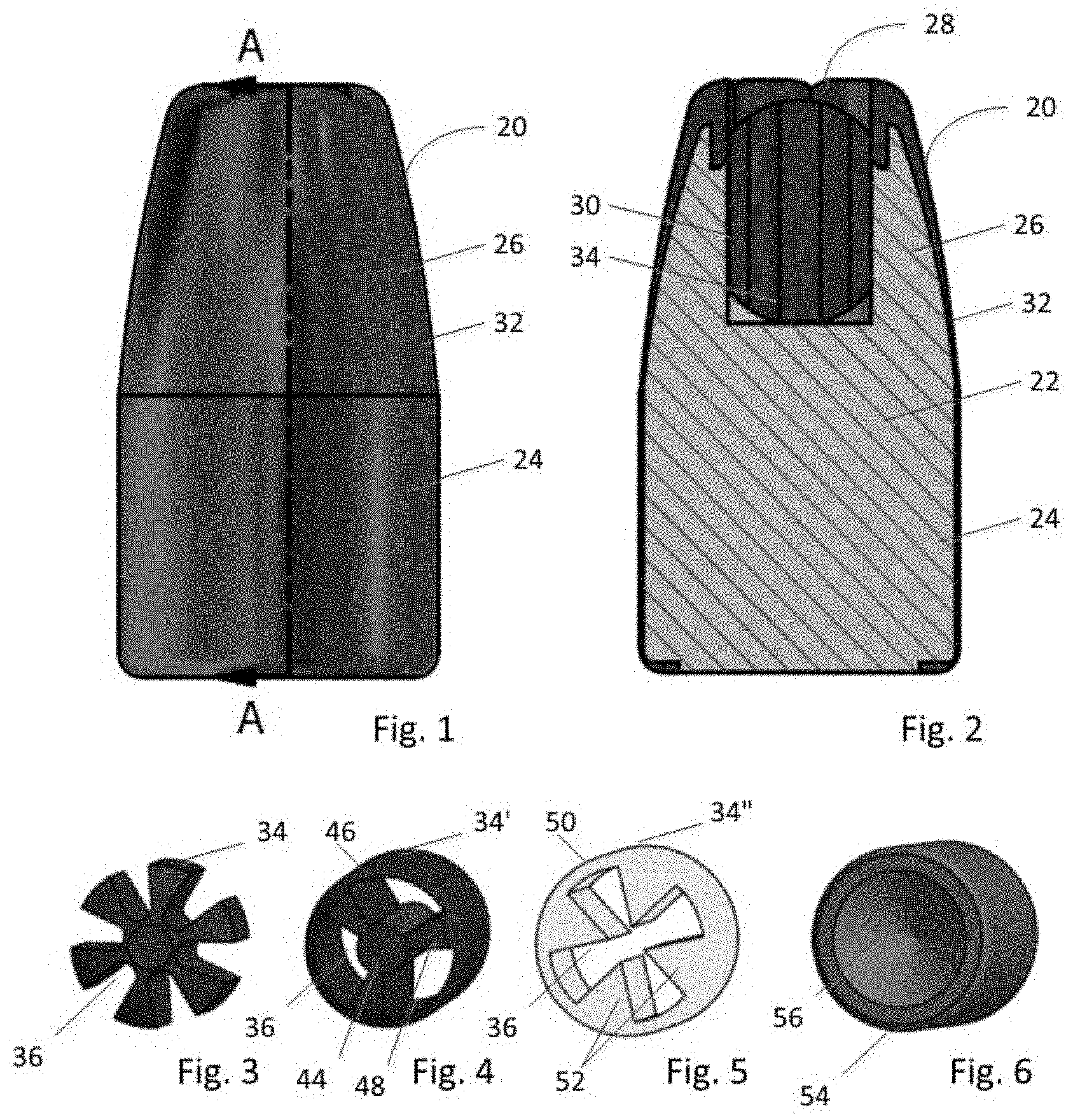
FIG. 1 is a side elevation view of a first preferred embodiment of a bullet constructed according to the principles of this invention;
FIG. 2 is a longitudinal cross sectional view of a the bullet shown in FIG. 1;
FIG. 3 is a perspective view of a section of the expander of the first preferred embodiment;
FIG. 4 is a perspective view of a section of the expander of a second preferred embodiment;
FIG. 5 is a perspective view of a section of the expander of a third preferred embodiment;
FIG. 6 is a perspective view of a section of the expander of the first preferred embodiment;
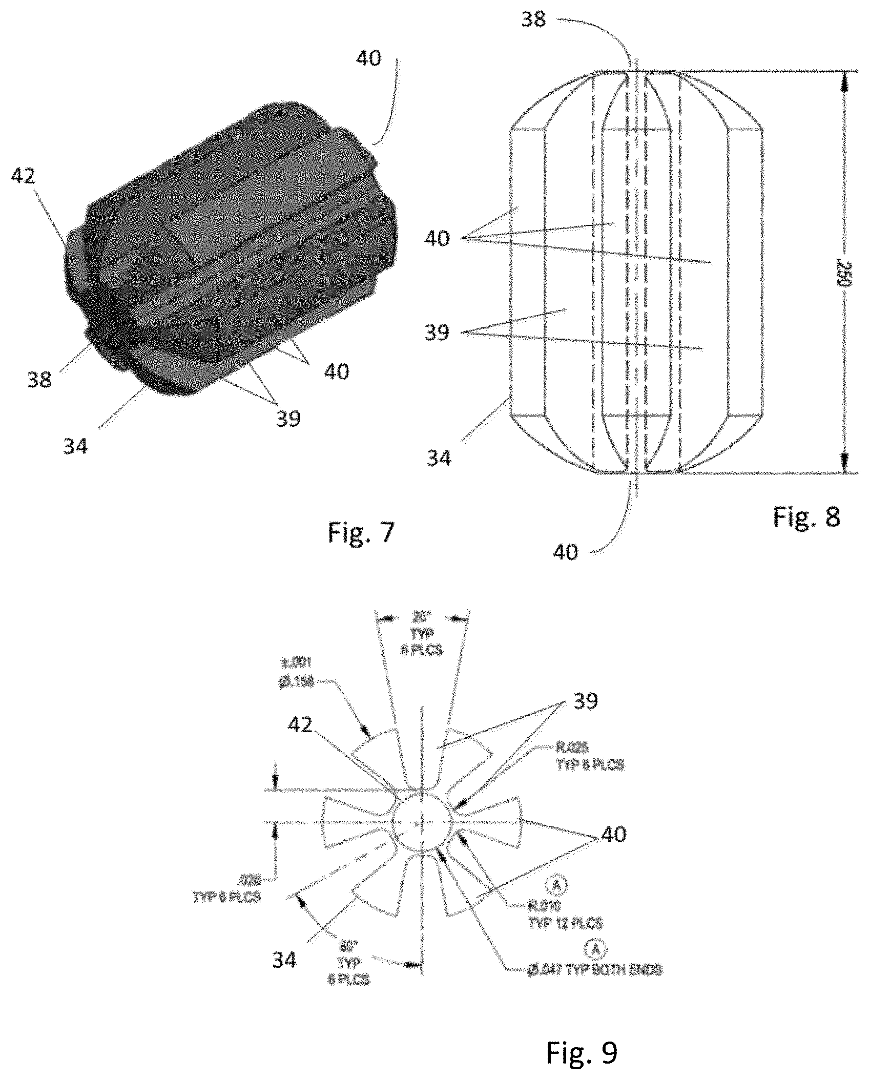
FIG. 7 is a perspective view of the expander of the first embodiment;
FIG. 8 is a side elevation view of the expander of the first embodiment; and
FIG. 9 is an end elevation view of the expander of the first embodiment.
Corresponding reference numerals indicate corresponding parts throughout the several views of the drawings.
DETAILED DESCRIPTION
Example embodiments will now be described more fully with reference to the accompanying drawings.
A first preferred embodiment of a bullet according to the principles of the present invention is indicated generally as 20 in FIGS. 1 and 2. The bullet 20 comprises a core 22, preferably of a soft, dense metal. The core 22 has a generally cylindrical rear section 24, a tapering front section 26, and an open forward end 28, opening to a cavity 30 formed therein. The cavity 30 has a generally cylindrical sidewall and a generally circular bottom. A jacket 32 of a harder metal than the core 22 surrounds at least the rear and front sections 24 and 26 of the core, and extends at least partially through the open forward end 28 and into the cavity 30. An expander 34 of a rigid polymer is disposed in the cavity. The expander 34 substantially fills the cavity 30, and has at least one passage 36 extending from its forward end 38 to its rearward end 40.
As shown in FIGS. 2-3 and 7-9, the expander 34 of the first preferred embodiment is preferably a generally cylindrical body 36, having a plurality of generally longitudinally extending flutes 39 formed in its exterior surface, defining a plurality of splines 40 between them, cooperating with the walls of the cavity 30 to form a plurality of passages 36 extending from the forward end 38 to the rearward end 40, effectively connecting the forward end of the bullet 20 with the bottom of the cavity. In this preferred embodiment there are six flutes 39, forming six generally wedge shaped splines 40, projecting from an axially extending hub 42. The forward and rearward ends 38 and 40 of the expander 34 are preferably higher in the center than adjacent the sides. In some embodiments, the ends of the expander 34 are pointed, in other embodiments the ends of the expander are dome-shaped, as shown in FIGS. 2-3 and 7-9.
Alternate embodiments of the expander 34 are indicated as 34' and 34'' in FIGS. 4 and 5. As shown in FIG. 4, expander 34' includes a central hub 44 surrounded by a circumferential ring 46, with three generally radially extending splines 48 between the hub and the ring, defining three passages 36 there through. As shown in FIG. 5, expander 34'' has a circumferential ring 50, with a plurality (4) inwardly extending wedge shaped members 52, defining a single passage 36 with a generally cross-shaped cross-section. The expander members 34, 34' and 34'' are preferably made from a relatively rigid polymer material, such as a high impact polystyrene. FIG. 6 shows an alternate to an expander member 34, comprising a plug 54 with a forward-facing dimple 56. The plug 54 can be made of a rigid polymeric material, but alternatively could be made of a highly resilient material, such as an elastomer. While plug 54 can improve performance in certain limited conditions, it does not perform as well as the expander members 34, 34' and 34'' which have passages therethrough, and in particular expander member 34 of the first preferred embodiment.
The passages 36 in the expander 34 comprise between about 30% and about 60% of the cross sectional area of the cavity 30, and more preferably between about 45% and about 60% of the cross sectional area of the cavity. It is believed that this allows sufficient passage through the expander and into the cavity to facilitate expansion of the bullet. The cross-sectional area of each passage is preferably less than about 0.004 in.sup.2, and more preferably less than about 0.002 in.sup.2. It is believed that this helps prevent materials from entering and clogging the passages,
The forward-most end 38 of the expander 34 preferably does not extend beyond the forward end of the core 22 and jacket 32. The center of mass of the bullet 20 is preferably rearward of the bottom of the cavity 30.
The core 22 is preferably lead or a lead alloy, but could also be of a non-lead metal or metal alloy. The core 22 can be pre-formed and inserted into the jacket 32, or the core can be formed in a drawn cup that becomes the jacket. The open forward end 28 and the cavity 30 can be formed by punching the bottom of the cup, during which operation the tapering front portion 26 can be shaped as well.
The jacket 32 is preferably copper or a copper alloy but could be some other material. Lines of weakness can be formed in the forward portion of the jacket 32 (including the portion that extends at least partly into the cavity 30) to facilitate the expansion of the bullet 20. These lines of weakness can be cuts through or partially through the jacket 32, lines of perforation, or lines of reduced thickness. The jacket 32 is preferably bonded to the core 22. This bonding can be a metallic bond, for example by forming the core in the jacket (as described above), or heating the jacket 32 and core 22 together. Alternatively the bonding can be formed with an adhesive or other agent. Lastly, the jacket can be mechanically bonded to the core, for example with knurling 60 on the jacket 32, that impinges and engages the core 22.
The invention also comprises cartridges made with bullets in accordance with the principles of this invention.
The foregoing description of the embodiments has been provided for purposes of illustration and description. It is not intended to be exhaustive or to limit the disclosure. Individual elements or features of a particular embodiment are generally not limited to that particular embodiment, but, where applicable, are interchangeable and can be used in a selected embodiment, even if not specifically shown or described. The same may also be varied in many ways. Such variations are not to be regarded as a departure from the disclosure, and all such modifications are intended to be included within the scope of the disclosure.
* * * * *
D00000
D00001
D00002
XML
uspto.report is an independent third-party trademark research tool that is not affiliated, endorsed, or sponsored by the United States Patent and Trademark Office (USPTO) or any other governmental organization. The information provided by uspto.report is based on publicly available data at the time of writing and is intended for informational purposes only.
While we strive to provide accurate and up-to-date information, we do not guarantee the accuracy, completeness, reliability, or suitability of the information displayed on this site. The use of this site is at your own risk. Any reliance you place on such information is therefore strictly at your own risk.
All official trademark data, including owner information, should be verified by visiting the official USPTO website at www.uspto.gov. This site is not intended to replace professional legal advice and should not be used as a substitute for consulting with a legal professional who is knowledgeable about trademark law.