Hydrophilic material oil fence having double-porous mesh
Kim , et al. February 9, 2
U.S. patent number 10,914,045 [Application Number 16/660,800] was granted by the patent office on 2021-02-09 for hydrophilic material oil fence having double-porous mesh. This patent grant is currently assigned to KOREA INSTITUTE OF SCIENCE AND TECHNOLOGY. The grantee listed for this patent is KOREA INSTITUTE OF SCIENCE AND TECHNOLOGY. Invention is credited to Seo Hyun Cho, Seong Jin Kim, O Chang Kwon, Myoung Woon Moon.


View All Diagrams
| United States Patent | 10,914,045 |
| Kim , et al. | February 9, 2021 |
Hydrophilic material oil fence having double-porous mesh
Abstract
Disclosed is a hydrophilic material oil fence having a double-porous mesh. The hydrophilic material oil fence having the double-porous mesh includes a floating body floating on a water surface, and a skirt coupled to an upper portion and a lower portion of the floating body and made of a hydrophilic material through which a hydrophilic fluid selectively passes. A mesh hole size of a partial region of the skirt and a mesh hole size of the other region of the skirt are different.
| Inventors: | Kim; Seong Jin (Seoul, KR), Moon; Myoung Woon (Seoul, KR), Kwon; O Chang (Seoul, KR), Cho; Seo Hyun (Seoul, KR) | ||||||||||
|---|---|---|---|---|---|---|---|---|---|---|---|
| Applicant: |
|
||||||||||
| Assignee: | KOREA INSTITUTE OF SCIENCE AND
TECHNOLOGY (Seoul, KR) |
||||||||||
| Family ID: | 1000005350432 | ||||||||||
| Appl. No.: | 16/660,800 | ||||||||||
| Filed: | October 23, 2019 |
Prior Publication Data
| Document Identifier | Publication Date | |
|---|---|---|
| US 20200123726 A1 | Apr 23, 2020 | |
Foreign Application Priority Data
| Oct 23, 2018 [KR] | 10-2018-0126738 | |||
| Current U.S. Class: | 1/1 |
| Current CPC Class: | E02B 15/06 (20130101); E02B 15/0814 (20130101); E02B 15/0864 (20130101); E02B 15/0807 (20130101); E02B 15/101 (20130101) |
| Current International Class: | E02B 15/06 (20060101); E02B 15/08 (20060101); E02B 15/10 (20060101) |
| Field of Search: | ;405/60,63 |
References Cited [Referenced By]
U.S. Patent Documents
| 3667235 | June 1972 | Preus |
| 3984987 | October 1976 | Light, Jr. |
| 4362631 | December 1982 | Bocard |
| 5056958 | October 1991 | Campbell |
| 5071286 | December 1991 | Separovich |
| 6558075 | May 2003 | Benedict |
| 6616383 | September 2003 | Janz |
| 6722817 | April 2004 | Benedict |
| 8465231 | June 2013 | Christopher |
| 8747027 | June 2014 | Singleton |
| 8807869 | August 2014 | Lee |
| 2016/0017559 | January 2016 | Rasmussen |
| 677242 | Apr 1991 | CH | |||
| 62041812 | Feb 1987 | JP | |||
| 101149032 | May 2012 | KR | |||
| 101648476 | Aug 2016 | KR | |||
| 1020180076882 | Jul 2018 | KR | |||
| WO-2012116548 | Sep 2012 | WO | |||
Other References
|
Korean Office Action for KR Application No. 10-2018-0126738 dated Apr. 28, 2020. cited by applicant. |
Primary Examiner: Lagman; Frederick L
Attorney, Agent or Firm: Cantor Colburn LLP
Claims
What is claimed is:
1. A hydrophilic material oil fence having a double-porous mesh, comprising: a floating body floating on a water surface; and a skirt coupled to a lower portion of the floating body and made of a hydrophilic material through which a hydrophilic fluid selectively passes, wherein a mesh hole size of a first partial region (A1) of the skirt and a mesh hole size of a second partial region (A2) of the skirt are different, wherein in the skirt, the first partial region (A1) is formed at an upper side, and the second partial region (A2) is formed at a lower side of the first partial region (A1), wherein the mesh hole size of the first partial region (A1) is smaller than the mesh hole size of the second partial region (A2), wherein the mesh hole size of the first partial region (A1) is 10 .mu.m or more and 30 .mu.m or less, wherein the mesh hole size of the second partial region (A2) is 100 .mu.m or more and 500 .mu.m or less, and wherein pressure of the skirt is less than 2 kPa when flow velocity is 1 knot.
2. The hydrophilic material oil fence having a double-porous mesh according to claim 1, wherein the floating body is formed to have a cylindrical shape or a polygonal pillar shape.
3. The hydrophilic material oil fence having a double-porous mesh according to claim 1, wherein the floating body has an air pocket provided at an inner portion or an outer portion thereof and made of a material having rubber or vinyl to increase buoyance.
4. The hydrophilic material oil fence having a double-porous mesh according to claim 1, wherein when the water surface and an area with a water depth less than 1 m have different flow velocities, the first partial region (A1) of the skirt is divided into two or more regions.
5. The hydrophilic material oil fence having a double-porous mesh according to claim 1, wherein a weight member is coupled and fixed to a lower end of the skirt.
6. The hydrophilic material oil fence having a double-porous mesh according to claim 5, wherein the weight member is fixed in a coupling hole fixed at the lower end of the skirt.
7. The hydrophilic material oil fence having a double-porous mesh according to claim 5, wherein the weight member is connected to the lower end of the skirt by a fixing member including a rope or a hook.
Description
CROSS-REFERENCE TO RELATED APPLICATION
This application claims priority to Korean Patent Application No. 10-2018-0126738, filed on 2018 Oct. 23, and all the benefits accruing therefrom under 35 U.S.C. .sctn. 119, the contents of which in its entirety are herein incorporated by reference.
BACKGROUND
1. Field
The present disclosure relates to a hydrophilic material oil fence having a double-porous mesh.
2. Description of the Related Art
Inadvertent spills of petroleum-based oil or hazardous and noxious substances (HNS) occur frequently in the ocean or river due to negligence or the like.
At this time, the petroleum-based oil or hazardous and noxious substances float to the surface of the ocean and river and rapidly spread to the surroundings, causing serious pollution to the surrounding environment, and enormous efforts are required to remove the petroleum-based oil or hazardous and noxious substances.
Thus, in the event of spill of oil or hazardous and noxious substances (HNS), it is important to respond promptly and reliably remove the oil or hazardous and noxious substances (HNS).
In general, when oil is spilled into the ocean or river, a primary spill preventer is provided by installing an oil boom, an oil capturing net, an oil fence, and the like, and an emulsifying agent is sprayed on the oil collected in the oil capturing net. Then, the oil is deposited on the seabed or recovered using oil recovery equipment such as an oil skimmer or adsorption cloth.
However, if the existing oil capturing net or oil fence is used, its balance may be lost or oil may be leaked therebelow due to strong water pressure caused by fast flow velocity in areas with strong tidal current or high wave height, thereby drastically reducing its effect. Thus, it is difficult to use the existing oil capturing net or oil fence in sea areas or rivers usually with a tidal current over 3 knots (about 1.5 m/sec).
RELATED LITERATURES
Patent Literature
Korean Patent No. 10-1149032, `Oil fence and its storage method`
SUMMARY
The present disclosure is designed based on the above background, and an object of the present disclosure is to use a hydrophilic oil-separating mesh material in a skirt portion, so that the entire skirt has a property of passing water but not passing oil and thus the skirt receives a less resisting force against a water pressure, thereby enabling to rapidly and reliably capture oil or hazardous and noxious substances in water stably even in areas with strong tidal currents or high wave heights having a high flow velocity.
At this time, when oil having a relatively low viscosity of less than 100 cSt, such as gasoline or diesel, is spilled, small pores of less than 30 .mu.m should be used to prevent the oil from leaking. In this case, excessive water pressure is applied to the net, so it is difficult to use the small pores at situations where the net is pulled at high speed or strong tidal current is present.
In the present disclosure, in order to solve the above difficulties, different from the conventional technique where the skirt is configured using a single-porous mesh, a hydrophilic oil-separating material having a small mesh hole size is disposed at an upper portion of the skirt where the oil spilled to the sea is mainly in contact, thereby improving oil recovery ability. Also, a hydrophilic oil-separating material with a large mesh hole size is disposed at a lower portion of the skirt to discharge water quickly, thereby minimizing the adverse effect caused by an increased water pressure.
In addition, by reducing the tension applied to a body of the fence due to the water pressure applied to the skirt, the skirt may be formed to have along length.
The object of the present disclosure is not limited thereto, and other objects not mentioned herein will be clearly understood by those skilled in the art from the following description.
In one aspect, there is provided a hydrophilic material oil fence having a double-porous mesh, comprising: a floating body floating on a water surface; and a skirt coupled to an upper portion and a lower portion of the floating body and made of a hydrophilic material through which a hydrophilic fluid selectively passes, wherein a mesh hole size of a partial region A1 of the skirt and a mesh hole size of the other region A2 of the skirt are different.
In addition, there is provided a hydrophilic material oil fence having a double-porous mesh, wherein in the skirt, the partial region A1 is formed at an upper side, and the other region A2 is formed at a lower side of the partial region A1.
In addition, there is provided a hydrophilic material oil fence having a double-porous mesh, wherein the mesh hole size of the partial region A1 is smaller than the mesh hole size of the other region A2.
In addition, there is provided a hydrophilic material oil fence having a double-porous mesh, wherein the mesh hole size of the partial region A1 is 10 .mu.m or more and 200 .mu.m or less.
In addition, there is provided a hydrophilic material oil fence having a double-porous mesh, wherein the mesh hole size of the other region A2 is 50 .mu.m or more and 500 .mu.m or less.
In addition, there is provided a hydrophilic material oil fence having a double-porous mesh, wherein the skirt has a length of 20 cm or more and 150 cm or less.
According to an embodiment of the present disclosure, since a hydrophilic oil-separating mesh material having two or more pore sizes is disposed at an upper portion and a lower portion of the skirt, the entire skirt is allowed to pass water, but the upper portion of the skirt where the hydrophilic oil-separating material with a small mesh hole size is disposed effectively prevents the oil from leaking out and water is rapidly discharged through the hydrophilic oil-separating material with a great mesh hole size disposed at the lower portion of the skirt, thereby drastically reducing the resisting force applied to the skirt. Thus, it possible to reliably and surely capture oil or hazardous and noxious substances in water stably even in areas with strong tidal currents or great wave heights.
In addition, even when strong water pressure is applied to the oil fence (skirt) since strong tidal current having a flow velocity over 3 knots is generated or a ship is moving at high speed to tow the oil fence for recovering oil, water effectively passes through the skirt, and thus the water pressure applied to the skirt is reduced, thereby preventing the oil from leaking due to damage or balance loss of the oil fence.
In addition, by reducing the tension applied to the skirt due to the water pressure, it is possible to form the skirt in a long length.
BRIEF DESCRIPTION OF THE DRAWINGS
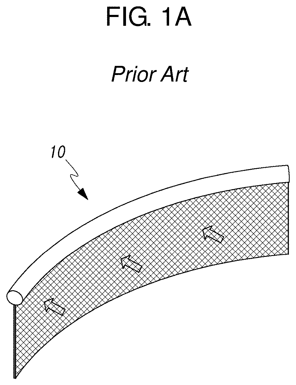
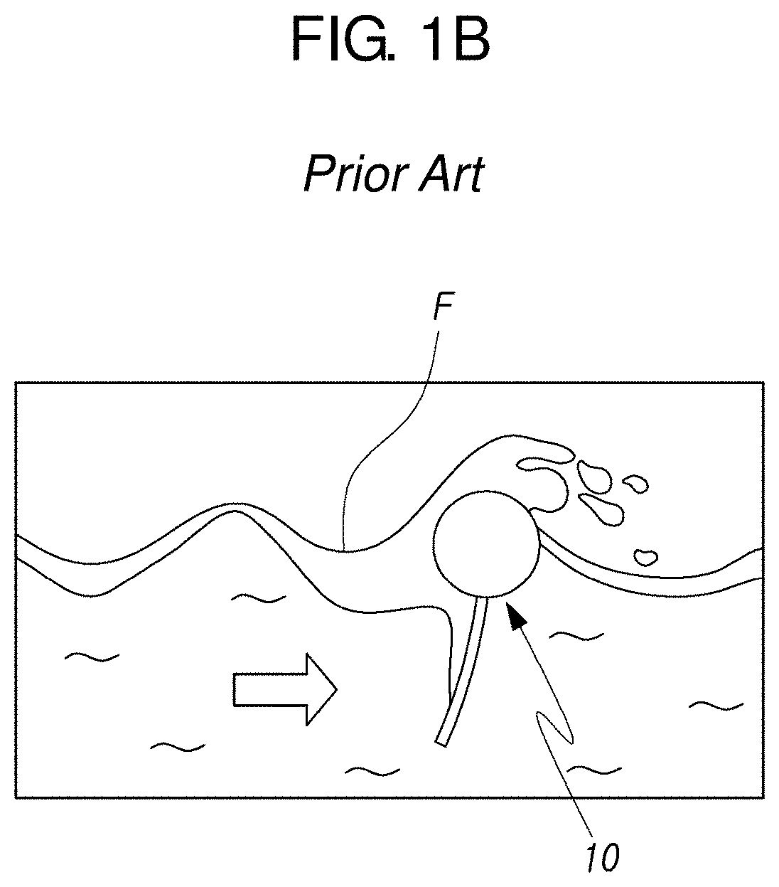
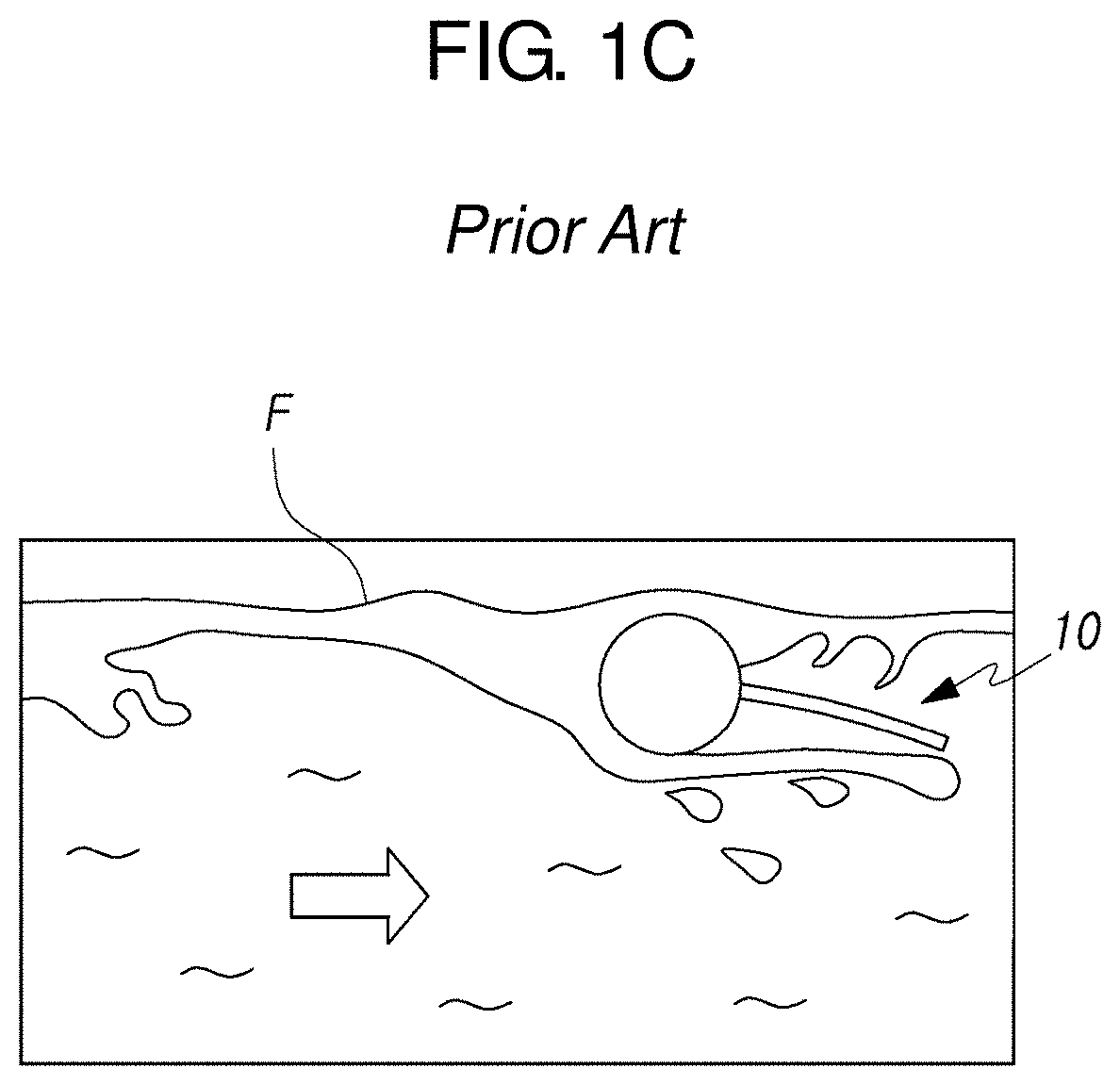
FIGS. 1A, 1B and 1C are diagrams showing a conventional oil fence, which blocks both water and oil.
FIG. 2 is a diagram showing a hydrophilic material oil fence having a double-porous mesh according to an embodiment of the present disclosure.
FIGS. 3 and 4 are diagrams for comparing pressures according to mesh hole sizes of a general oil fence, an oil fence having a single-pore mesh and the oil fence having a double-porous mesh.
FIG. 5 is a diagram showing an experiment result table of the oil fence having a single-pore mesh and the oil fence having a double-porous mesh according to an embodiment of the present disclosure.
FIGS. FIGS. 6A and 6B are diagrams showing an experiment result table of the oil fence having a single-pore mesh in FIG. 5.
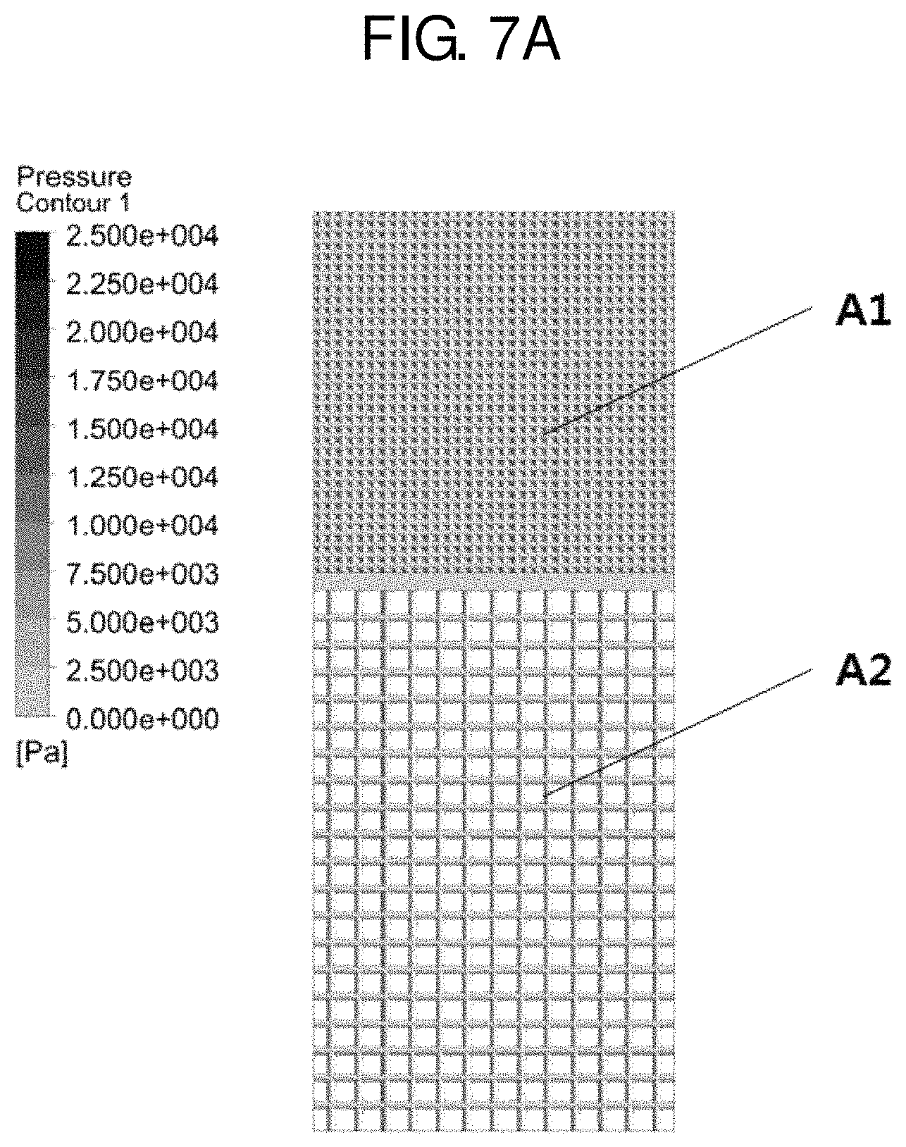
FIGS. 7A and 7B are diagrams showing an experiment result table of the oil fence having a double-porous mesh according to an embodiment of the present disclosure in FIG. 5.
DETAILED DESCRIPTION
Hereinafter, some embodiments of the present disclosure will be described in detail with reference to exemplary drawings. In adding reference signs to components of each drawing, it should be noted that the same reference signs are assigned to the same components as much as possible even though they are shown in different drawings. Also, in describing the present disclosure, if it is determined that a detailed description of the related known structure or function may obscure the gist of the present disclosure, the detailed description thereof will be omitted.
In addition, in describing the components of the present disclosure, terms such as "first", "second", "A", "B", "(a)" and "(b)" may be used. These terms are only for distinguishing the corresponding component from another component, and the nature, order or sequence of the components are not limited by the terms. If a component is described as being "connected", "coupled" or "contacted" to another component, that component may be directly connected or contacted to another component, but it should also be understood that any other element(s) may be further "connected", "coupled" or "contacted" between these component.
FIGS. 1A, 1B and 1C are diagrams showing a conventional oil fence, which blocks both water and oil.
FIG. 2 is a diagram showing a hydrophilic material oil fence having a double-porous mesh according to an embodiment of the present disclosure.
FIGS. 3 and 4 are diagrams for comparing pressures according to mesh hole sizes of a general oil fence, an oil fence having a single-pore mesh and the oil fence having a double-porous mesh.
FIG. 5 is a diagram showing an experiment result table of the oil fence having a single-pore mesh and the oil fence having a double-porous mesh according to an embodiment of the present disclosure.
FIGS. 6A and 6B are diagrams showing an experiment result table of the oil fence having a single-pore mesh in FIG. 5.
FIGS. 7A and 7B are diagrams showing an experiment result table of the oil fence having a double-porous mesh according to an embodiment of the present disclosure in FIG. 5.
As shown in these figures, a hydrophilic material oil fence 200 with a double-porous mesh according to an embodiment of the present disclosure includes a floating body 201 floating on a water surface; and a skirt 203 coupled to a lower portion of the floating body 201 and made of a hydrophilic material through which a hydrophilic fluid selectively passes, wherein a mesh hole size of a partial region A1 of the skirt and a mesh hole size of the other region A2 of the skirt are different.
In the figures, mesh pores are exaggerated to clearly show different mesh hole sizes.
Meanwhile, in the case of the conventional oil fence 10 that block both water and oil, as shown in FIG. 1A, FIG. 1B and FIG. 1C, when a strong tidal current occurs or when a ship is towing the oil fence 10 while driving at high speed for oil recovery, the oil fence 10 is damaged and loses balance due to a strong water pressure(arrows shown in the FIG. 1A, FIG. 1B and FIG. 1C) applied to the oil fence 10, and thus the oil F leaks out of the oil fence 10. However, according to an embodiment of the present disclosure, the above problem is solved.
Hereinafter, each component is explained in full detail.
The floating body 201 is formed to float on the water surface. For example, the floating body 201 may be formed to have a cylinder shape, a polygonal pillar shape, or the like, and its length may also vary.
Of course, in order to improve the buoyancy of the floating body 201, for example, an air pocket made of rubber or vinyl may be installed to an inner side or an outer side of the floating body 201.
Subsequently, the skirt 203 is coupled to the upper portion or the lower portion of the floating body 201.
The skirt 203 is made of a hydrophilic material through which a hydrophilic fluid selectively passes.
Here, the hydrophilic material may selectively use a mesh having different hole sizes.
Of course, the skirt 203 may be formed by coupling a hydrophilic separator made of a hydrophilic material to a surface thereof.
Meanwhile, in the skirt 203, the mesh hole size of the partial region A1 and the mesh hole size of the other region A2 are different.
More specifically, the partial region A1 of the skirt 203 is formed at an upper side, and the other region A2 is formed at a lower side of the partial region A2.
More specifically, the mesh hole size of the partial region A1 of the skirt 203 is smaller than the mesh hole size of the other region A2.
For example, the partial region A1 of the skirt 203 may be formed to have a mesh pore size 10 .mu.m or more and 200 .mu.m or less, and the other region A2 may be formed to have a mesh pore size 50 .mu.m or more and 500 .mu.m or less so that oil is suppressed not to pass and water passes therethrough more quickly than the partial region A1.
As a result, the hydrophilic material oil fence 200 having a double-porous mesh according to an embodiment of the present disclosure allows water to pass easier while suppressing oil not to pass.
Meanwhile, if a site where the oil fence 200 is to be installed has a small depth or the flow velocity in an area with a water depth less than 1 m is different from the flow velocity of the water surface, the partial region A1 of the skirt 203 may be divided into two or more regions.
In addition, the skirt 203 may be, for example, formed to have a length of 20 cm or more and 150 cm or less.
Moreover, although not shown in the figures, a weight member may be coupled and fixed to a lower end of the skirt 203. The weight member may be fixed to a coupling hole formed at the lower end of the skirt 203 or be connected and fixed to the lower end of the skirt 203 by a fixing member such as a rope or a hook.
Meanwhile, in the case of a general oil fence having a skirt through which both water and oil cannot pass, a pressure of about 800 kPa is applied to the skirt by a flow velocity of 1 knot. However, in the hydrophilic material oil fence having a double-porous mesh according to an embodiment of the present disclosure, it can be found that the pressure applied to the skirt is sharp decreased to about 3 kPa, even to about 1 kPa, when the skirt has a general thickness of 50 .mu.m to 100 .mu.m.
As described above, according to an embodiment of the present disclosure, the entire skirt allows water to pass therethrough, but the hydrophilic oil-separating material having dense mesh pores is disposed at the upper portion of the skirt that is primarily in contact with oil, thereby preventing the oil from leaking. In addition, since the hydrophilic oil-separating material with a large mesh hole size is disposed at the lower portion of the skirt, it is possible to prevent the unnecessary increase of resisting force, compared to the conventional technique using a single-porous mesh. Thus, it is possible to rapidly and surely capture oil or hazardous and noxious substances in water stably even in areas with strong tidal currents or high wave heights having a high flow velocity.
In addition, even when a strong water pressure is applied to the oil fence (skirt) since oil is recovered in areas where a strong tidal current with a flow velocity over 3 knots flows or since a ship is moving at high speed to tow the oil fence for recovering oil, the pressure applied to the skirt is reduced due to the effective passage of water, thereby preventing the oil from spilling due to breakage or balance loss of the oil fence.
In addition, by reducing the tension applied to the skirt due to the water pressure, it is possible to form the skirt in a long length.
Here, the description of the present disclosure is not necessarily limited to the above embodiments, even though all of the components constituting the embodiment of the present disclosure are described as being combined into a single unit or operating in combination. In other words, within the scope of the present disclosure, all of the components may be selectively combined and operated.
In addition, the terms "comprise", "include" or "have" used above mean that the corresponding component is capable of including elements unless otherwise stated, and thus, it should be construed that it may further include other components, without including other components. All terms, including technical and scientific terms, have the same meaning as commonly understood by those skilled in the art, unless otherwise defined. Commonly used terms, such as those defined in a dictionary, should be construed as being consistent with the contextual meaning of the related art and shall not be construed in an ideal or overly formal sense unless explicitly stated in the present disclosure.
The above description is merely illustrative of the technical idea of the present disclosure, and a person skilled in the art may make various modifications and changes without departing from the essential characteristics of the present disclosure. Accordingly, the embodiments in the present disclosure are not intended to limit the technical scope of the present disclosure but to illustrate the present disclosure, and the scope of the present disclosure is not limited by these embodiments. The scope of the present disclosure should be defined by the appended claims, and any technical idea falling within the scope of the present disclosure shall be construed as being included in the scope of the present disclosure.
REFERENCE SIGNS
10: oil fence 200: oil fence 201: floating body 203: skirt
* * * * *
D00000
D00001
D00002
D00003
D00004
D00005
D00006
D00007
D00008
D00009
D00010
D00011
XML
uspto.report is an independent third-party trademark research tool that is not affiliated, endorsed, or sponsored by the United States Patent and Trademark Office (USPTO) or any other governmental organization. The information provided by uspto.report is based on publicly available data at the time of writing and is intended for informational purposes only.
While we strive to provide accurate and up-to-date information, we do not guarantee the accuracy, completeness, reliability, or suitability of the information displayed on this site. The use of this site is at your own risk. Any reliance you place on such information is therefore strictly at your own risk.
All official trademark data, including owner information, should be verified by visiting the official USPTO website at www.uspto.gov. This site is not intended to replace professional legal advice and should not be used as a substitute for consulting with a legal professional who is knowledgeable about trademark law.