Pedestal enclosure for utility components
Huffstetler , et al. February 2, 2
U.S. patent number 10,910,802 [Application Number 16/094,664] was granted by the patent office on 2021-02-02 for pedestal enclosure for utility components. This patent grant is currently assigned to Hubbell Incorporated. The grantee listed for this patent is Hubbell Incorporated. Invention is credited to Robert Wilton Fox, Jeffrey Scott Huffstetler.

| United States Patent | 10,910,802 |
| Huffstetler , et al. | February 2, 2021 |
Pedestal enclosure for utility components
Abstract
A pedestal housing for utility connections includes a lower section having a plurality of walls, an upper surface, and a bottom opening. A first rim is formed on the lower section positioned below the upper surface. A second rim is formed on the lower section positioned below the first rim. An upper section includes a plurality of walls and a top. The upper section is releasably connected to the lower section to form a housing for receiving one or more utility components. The upper section is configured to mate with one of the first rim or the second rim.
| Inventors: | Huffstetler; Jeffrey Scott (Friendsville, TN), Fox; Robert Wilton (Greenback, TN) | ||||||||||
|---|---|---|---|---|---|---|---|---|---|---|---|
| Applicant: |
|
||||||||||
| Assignee: | Hubbell Incorporated (Shelton,
CT) |
||||||||||
| Family ID: | 1000005338212 | ||||||||||
| Appl. No.: | 16/094,664 | ||||||||||
| Filed: | April 20, 2017 | ||||||||||
| PCT Filed: | April 20, 2017 | ||||||||||
| PCT No.: | PCT/US2017/028568 | ||||||||||
| 371(c)(1),(2),(4) Date: | October 18, 2018 | ||||||||||
| PCT Pub. No.: | WO2017/184838 | ||||||||||
| PCT Pub. Date: | October 26, 2017 |
Prior Publication Data
| Document Identifier | Publication Date | |
|---|---|---|
| US 20190123533 A1 | Apr 25, 2019 | |
Related U.S. Patent Documents
| Application Number | Filing Date | Patent Number | Issue Date | ||
|---|---|---|---|---|---|
| 62325141 | Apr 20, 2016 | ||||
| Current U.S. Class: | 1/1 |
| Current CPC Class: | H02G 3/10 (20130101); H02G 3/0493 (20130101) |
| Current International Class: | H02G 3/04 (20060101); H02G 3/10 (20060101) |
References Cited [Referenced By]
U.S. Patent Documents
| 2808135 | October 1957 | Moran |
| 2916539 | December 1959 | Hamilton |
| 2916591 | December 1959 | Benn |
| 3055970 | September 1962 | Handley |
| 3153116 | October 1964 | Phillips |
| 3257496 | June 1966 | Hamilton |
| 3309456 | March 1967 | Connell |
| 3373276 | March 1968 | Klein |
| 3435124 | March 1969 | Channell |
| 3652779 | March 1972 | Grinols |
| 3691288 | September 1972 | Sturdivan |
| 3714369 | January 1973 | Bunten |
| 3769460 | October 1973 | Charles |
| 3812279 | May 1974 | Voegeli |
| 3858755 | January 1975 | Tellen |
| 3928712 | December 1975 | Sears |
| 4015397 | April 1977 | Flachbarth |
| 4097683 | June 1978 | Summers |
| 4163503 | August 1979 | McKinnon |
| 4284300 | August 1981 | Campbell |
| 4365108 | December 1982 | Bright |
| 4382155 | May 1983 | Borin |
| 4415217 | November 1983 | Clabburn |
| 4519657 | May 1985 | Jensen |
| 4626616 | December 1986 | Masters |
| 4631353 | December 1986 | Marks |
| 4751610 | June 1988 | Nickola |
| 4873600 | October 1989 | Vogele |
| 4887187 | December 1989 | Nickola |
| 4892978 | January 1990 | Axworthy |
| 5184279 | February 1993 | Horn |
| 5196988 | March 1993 | Horn |
| 5210374 | May 1993 | Channell |
| D354739 | January 1995 | Durham |
| 5384427 | January 1995 | Volk |
| 5400212 | March 1995 | Hanson |
| 5401902 | March 1995 | Middlebrook |
| D367464 | February 1996 | Jones |
| 5611616 | March 1997 | Chandler |
| 5734776 | March 1998 | Puetz |
| 5860715 | January 1999 | Lohde |
| D434001 | November 2000 | Sayger |
| 6182846 | February 2001 | Leschinger |
| 6501015 | December 2002 | Maloney |
| 6586671 | July 2003 | Kelley |
| 6877886 | April 2005 | Schuster |
| 6975505 | December 2005 | Wise |
| 7045710 | May 2006 | Allen |
| 7351909 | April 2008 | Harwood |
| 7357009 | April 2008 | Maloney |
| 7361832 | April 2008 | Dively |
| 7385137 | June 2008 | Burke et al. |
| 7700874 | April 2010 | Maloney |
| 7807924 | October 2010 | Wurzer |
| 8089747 | January 2012 | Storck |
| 9382722 | July 2016 | Banyi |
| 9768592 | September 2017 | Unger |
| 9991689 | June 2018 | Drueke |
| 10053861 | August 2018 | Lavery |
| 10158221 | December 2018 | Seff |
| 2001/0018978 | September 2001 | Gordin |
| 2002/0096346 | July 2002 | Maloney |
| 2005/0103780 | May 2005 | Maloney |
| 2005/0215090 | September 2005 | Harwood |
| 2005/0275319 | December 2005 | Wittmeier |
| 2005/0285011 | December 2005 | Harwood |
| 2006/0090917 | May 2006 | Lowe et al. |
| 2006/0254794 | November 2006 | Burke |
| 2007/0182567 | August 2007 | Stewart |
| 2008/0253061 | October 2008 | Seff |
| 2008/0253062 | October 2008 | Seff |
| 2009/0057119 | March 2009 | Burkett |
| 2010/0051310 | March 2010 | Wurzer |
| 2010/0052549 | March 2010 | Hudson |
| 2012/0256810 | October 2012 | Caldwell |
| 2012/0307069 | December 2012 | Pierce |
| 2014/0196380 | July 2014 | Burke |
Other References
|
PCT/US2017/028568 International Search Report and Written Opinion dated Jul. 21, 2017 (15 pages). cited by applicant. |
Primary Examiner: Tran; Binh B
Assistant Examiner: Robinson; Krystal
Attorney, Agent or Firm: Michael Best & Friedrich, LLP
Parent Case Text
RELATED APPLICATION(S)
This application is based on U.S. provisional application Ser. No. 62/325,141, filed Apr. 20, 2016, the disclosure of which is incorporated herein by reference in its entirety and to which priority is claimed.
Claims
What is claimed:
1. A pedestal housing for utility connections comprising: a lower section having a plurality of walls, an upper surface, and a bottom opening; a first rim formed on the lower section positioned below the upper surface; a second rim formed on the lower section positioned below the first rim; a first upper section having a plurality of walls and a top, the first upper section configured to be releasably connected to the lower section to form a housing for receiving one or more first sets of utility components, the first upper section configured to mate with the first rim, wherein the first upper section encloses the upper surface when connected to the first rim; and a second upper section having a plurality of walls and a top, the second upper section configured to be releasably connected to the lower section to form a housing for receiving one or more second sets of utility components, the second upper section configured to mate with the second rim, wherein the second upper section encloses the upper surface when connected to the second rim.
2. The pedestal housing of claim 1, wherein a flange extends from a lower portion of the walls.
3. The pedestal housing of claim 1, wherein a groove is formed around the plurality of walls.
4. The pedestal housing of claim 1, wherein the upper surface includes one or more mounting features.
5. The pedestal housing of claim 1, wherein the first upper section includes a first cover having a bottom lip configured to mate with the first rim.
6. The pedestal housing of claim 5, wherein the upper section further includes a bracket and an insert.
7. The pedestal housing of claim 6, wherein the bracket is connected to the upper surface and the insert is connected to the bracket.
8. The pedestal housing of claim 6, wherein the insert includes a mounting plate configured to receive one or more utility connectors.
9. The pedestal housing of claim 1, wherein the second upper section includes a second cover having a bottom lip configured to mate with the second rim.
10. A pedestal housing for utility connections comprising: a base comprising, a plurality of walls surrounding an interior and a bottom opening, an upper surface extending from the plurality of walls at least partially over the interior and defining a central opening, a first rim positioned below the upper surface, and a second rim positioned below the first rim in a stepped configuration; a first cover configured to mate with the first rim, wherein the first cover encloses the upper surface and the central opening when connected to the first rim; and a second cover configured to mate with the second rim, wherein the second cover encloses the upper surface and the central opening when connected to the second rim.
11. The pedestal housing of claim 10, wherein the first cover includes a bottom lip configured to mate with the first rim.
12. The pedestal housing of claim 10, further comprising a bracket connected to the upper surface and an insert connected to the bracket.
13. The pedestal housing of claim 12, wherein the insert includes a mounting plate configured to receive one or more utility connectors.
14. The pedestal housing of claim 10, wherein the second cover includes a bottom lip configured to mate with the second rim.
15. The pedestal housing of claim 10, wherein a flange extends from a lower portion of the plurality of walls.
16. The pedestal housing of claim 10, wherein the upper surface includes a set of openings fastener openings positioned around the central opening.
17. The pedestal housing of claim 16, wherein a bracket is connected the upper surface by one or more fasteners extending through the fastener openings.
Description
FIELD
Various exemplary embodiments relate to pedestals for housing utility transmission components.
BACKGROUND
Utility grids such as power, communication, or water lines and metering components, require a network of components spread over large areas. At certain points in the network, enclosures and access points are required. For example, at different connection points it is important to provide access to a user or worker to service the connection or run additional lines from the connection point. Examples of typical enclosures include underground vaults and pedestals. Underground vaults provide in ground housing for components while pedestals are typically used for above ground housing and access.
SUMMARY
According to various exemplary embodiments, a pedestal housing for utility connections includes a lower section having a plurality of walls, an upper surface, and a bottom opening. A first rim is formed on the lower section positioned below the upper surface. A second rim is formed on the lower section positioned below the first rim. An upper section includes a plurality of walls and a top. The upper section is releasably connected to the lower section to form a housing for receiving one or more utility components. The upper section is configured to mate with one of the first rim or the second rim.
According to another exemplary embodiment, a base of a pedestal housing for utility connections includes a plurality of walls surrounding an interior and a bottom opening. An upper surface extends from the plurality of walls at least partially over the interior. A first rim is positioned below the upper surface and a second rim positioned below the first rim.
According to another exemplary embodiment, a pedestal housing for utility connections includes a base and a cover. The base includes a plurality of walls surrounding an interior and a bottom opening. An upper surface extends from the plurality of walls at least partially over the interior. A first rim is positioned below the upper surface. A second rim positioned below the first rim. The cover is configured to mate with the first rim or the second rim.
According to another exemplary embodiment, a pedestal housing product line for utility connections includes a base, a first cover, and a second cover. The base includes a plurality of walls surrounding an interior and a bottom opening. An upper surface extends from the plurality of walls at least partially over the interior. A first rim is positioned below the upper surface. A second rim is positioned below the first rim. A first cover is configured to mate with the first rim. A second cover is configured to mate with the second rim.
Another exemplary embodiment is directed to a method of installing a pedestal housing. A base is positioned to receive a utility component. The base includes a plurality of walls surrounding an interior and a bottom opening. An upper surface extends from the plurality of walls at least partially over the interior. A first rim is positioned below the upper surface, and a second rim is positioned below the first rim. A selection is made between one of a first cover and a second cover. The first cover has a first configuration and the second cover has a second configuration. The selected first or second cover is connected to the base.
Another exemplary embodiment is directed to a method of making a pedestal housing. A base is formed having, a plurality of walls surrounding an interior and a bottom opening, and an upper surface extending from the plurality of walls at least partially over the interior. A first rim is formed below the upper surface, and a second rim is formed below the first rim. A first cover configured to mate with the first rim is formed. A second cover configured to mate with the second rim is formed.
BRIEF DESCRIPTION OF THE DRAWINGS
The aspects and features of various exemplary embodiments will be more apparent from the description of those exemplary embodiments taken with reference to the accompanying drawings, in which:
FIG. 1 is a top perspective view of an exemplary pedestal base;
FIG. 2 is a bottom perspective view of FIG. 1;
FIG. 3 is a top view of FIG. 1;
FIG. 4 is a side, sectional view of FIG. 1;
FIG. 5 is a perspective view of the base of FIG. 1 and a first exemplary cover;
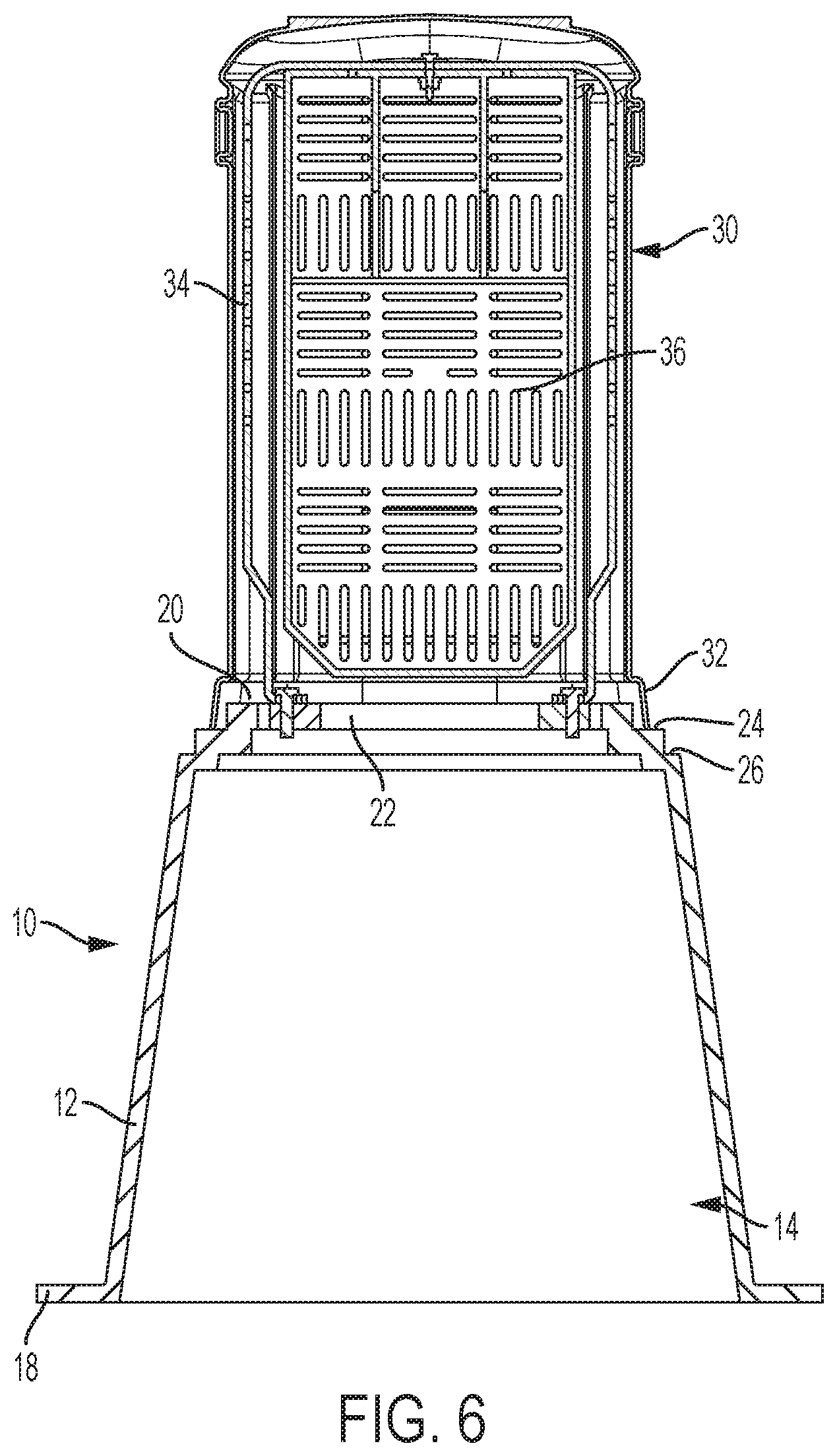
FIG. 6 is a side, sectional view of FIG. 5 with the cover connected to the base;
FIG. 7 is a perspective view of the base of FIG. 1 and a second exemplary cover; and
FIG. 8 is a side, sectional view of FIG. 7 with the cover connected to the base.
DETAILED DESCRIPTION OF EXEMPLARY EMBODIMENTS
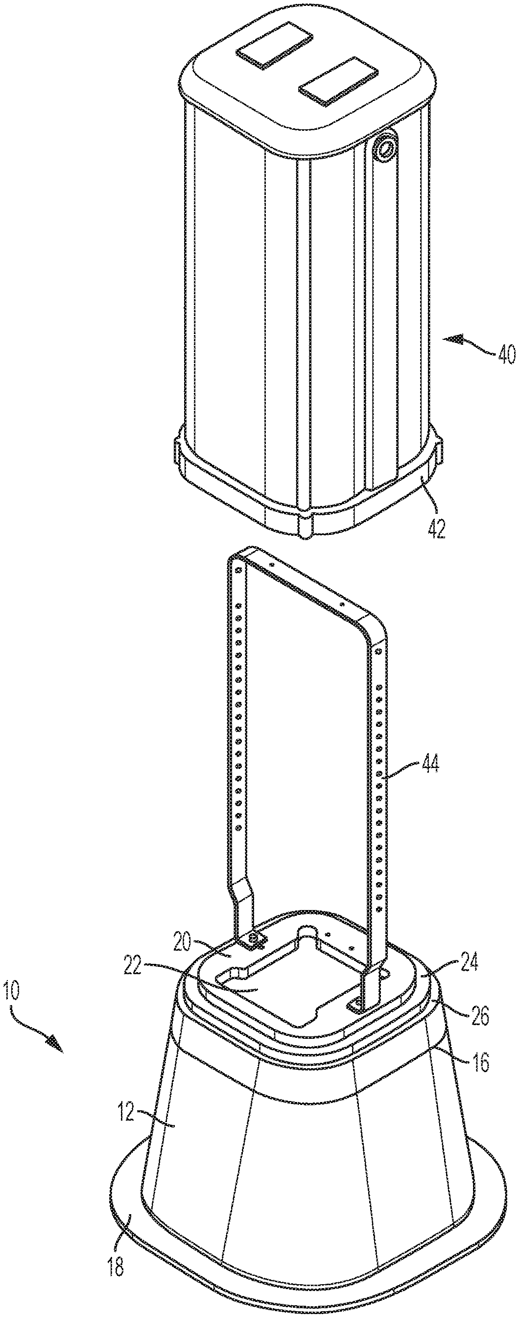
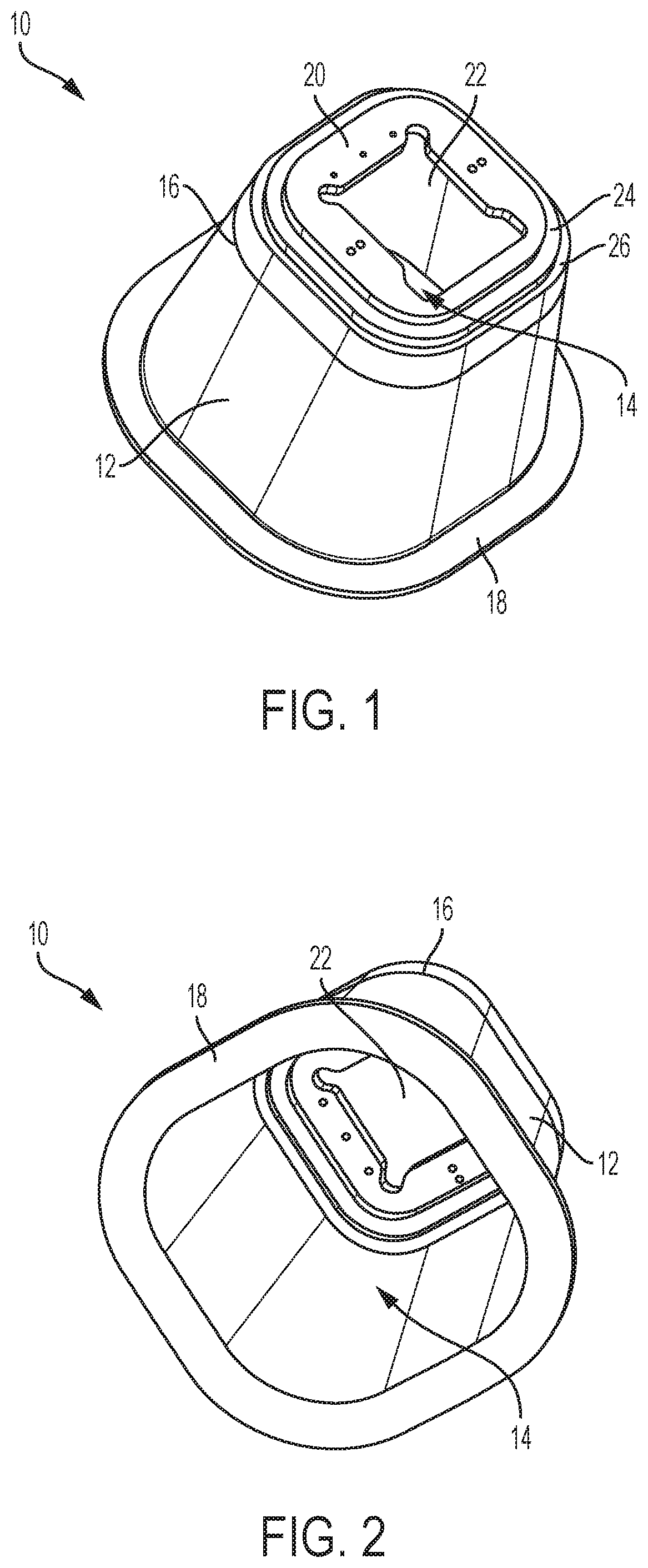
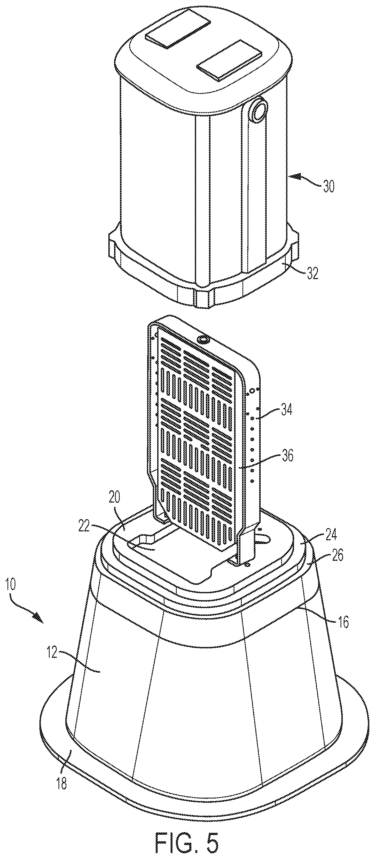
FIGS. 1-6 show exemplary embodiments that can be incorporated into a pedestal configured to contain various utility components. The pedestal can be secured to the ground or connected to another structure, such as an underground vault. Pedestal housings can be entirely above ground or recessed in the ground and extending therefrom. According to an exemplary embodiment, the pedestal includes a base 10 and a cover 12 that form a housing.
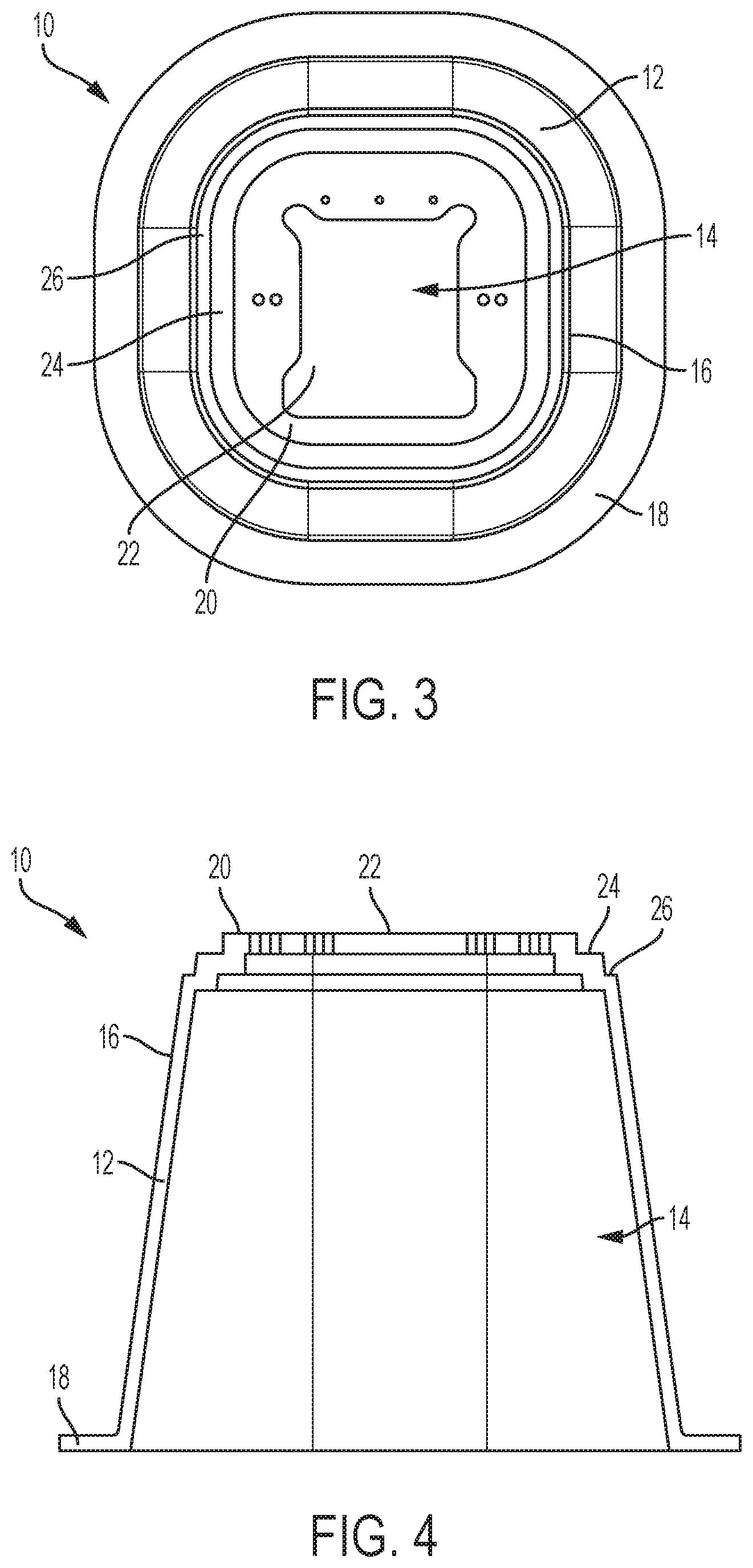
FIGS. 1-4 show an exemplary embodiment of a base 10. The base 10 includes a plurality of side walls 12 having rounded corners that surround an interior 14. A bottom opening provides access to the interior 14 from below, allowing utility lines to be run into the base 10. A groove 16 is formed around the side walls 12. A flange 18 extends from a lower portion of the side walls 12. The base 10 includes an upper surface 20 and a central opening 22 that provides access to the interior 14. The upper surface 20 includes one or more mounting features, for example openings, for connecting components to the base 10. In various exemplary embodiments, the number of side walls 12 can vary and can include a single, curvilinear side wall 12. The size, shape, and configuration of the base 10 can vary depending on the desired usage, for example taking into consideration space and load requirements. The base 10 can be made from a material that includes a polymer, such as a thermoplastic, concrete, a polymer-concrete blend, fiberglass or other suitable materials. The base 10 can be formed through a molding or casting procedure.
In an exemplary embodiment, the base 10 includes a first rim 24 and a second rim 26. The first rim 24 is positioned below the upper surface 20 and positioned above the second rim 26. The second rim 26 extends out from the first rim 24 in a stepped fashion to be wider than the first rim 24. Typically a pedestal base is designed to work with a single type and size of cover. The first and second rims 24, 26 allow the base 10 to accommodate different types of covers and different types of interior components than could be used in other pedestals. The first and second rims 24, 26 receive various covers and help prevent objects and debris from entering the housing.
FIGS. 5 and 6 show an exemplary embodiment of a first cover 30 and a set of components connected to the base 10. The first cover 30 includes a bottom lip 32 designed to mate with the first rim 24 of the base. The components include a bracket 34 and an insert 36. Other accessories can be incorporated as would be understood by one of ordinary skill in the art. The bracket 34 connects to the upper surface 20 of the base 10, for example through one or more fasteners. In an exemplary embodiment, the insert 36 includes a mounting plate that receives one or more utility connectors, for example terminal blocks or splitters. The first cover 30 can be made from a material that includes polymer, such as a thermoplastic, concrete, a polymer-concrete blend, fiberglass or other suitable materials. The first cover 30 can be formed through a molding or casting procedure, for example rotational molding.
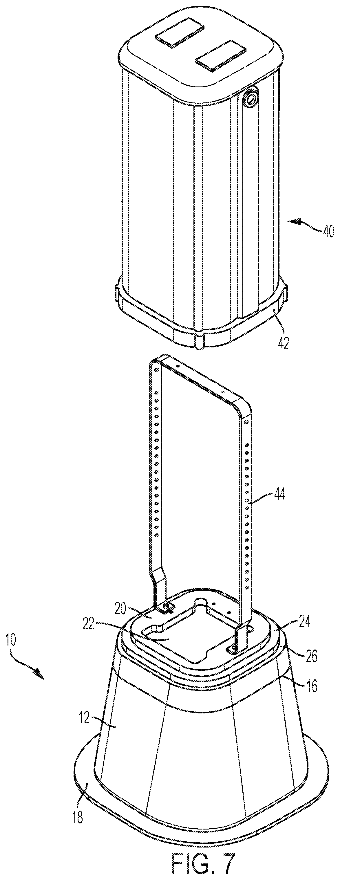
FIGS. 7 and 8 show an exemplary embodiment of a second cover 40 and a set of components connected to the base 10. The second cover 40 includes a bottom lip 42 designed to mate with the second rim 26 of the base. Although only a bracket 44 is shown, other accessories can be incorporated as would be understood by one of ordinary skill in the art. The bracket 44 connects to the upper surface of the base, for example through one or more fasteners. The second cover 40 can be made from a material that includes a polymer, such as a thermoplastic, concrete, a polymer-concrete blend, fiberglass or other suitable materials. The second cover 40 can be formed through a molding or casting procedure, for example rotational molding.
In an exemplary embodiment, the first cover 30 shown in FIG. 5 has a first width and the second cover 40 shown in FIG. 6 has a second width that is greater than the first width. For example, the first cover 30 can have a 10 inch width and the second cover 40 can have a 12 inch width. The first cover 30 can be configured to mate with the first rim 24 while the second cover 40 is configured to mate with the second rim 26.
According to an exemplary embodiment the base 10 is made from polymer concrete, the first and second covers 30, 40 are made from polyethylene, for example low-density polyethylene (LDPE), and the brackets 34, 44 are made from aluminum. Because the base 10 is made from polymer concrete, more interior room space is provided, allowing for storage of slack cable or similar application in the fiber optic, telephone, or electric utility industries. The base 10 is also capable of being installed so that up to 4-inches of the base can be left above grade level, allowing for protection of the pedestal from damage caused by mowing equipment.
In various exemplary embodiments, other parts and accessories can be associated with the pedestal as would be understood by one of ordinary skill in the art. For example a lock mechanism may be provided between the cover and the base. Different types of inserts and connectors other than the ones shown may also be used.
Various exemplary embodiments are directed to methods of making and installing a pedestal. The base 10 can be formed to include a plurality of side walls 12, an upper surface 20, a first rim 24, and a second rim 26. In an exemplary embodiment the base 10 can be formed from molding or casting. The base 10 can be installed on or in a surface, for example the ground or on top of an underground enclosure. A first cover 30 having a first configuration and a second cover 40 having a second configuration are provided and one of the first cover 30 and the second cover 40 is selected and connected to the base 10. The first rim 24 of the base 10 can be configured to mate with the first cover 30 and the second rim 26 can be configured to mate with the second cover 40. The base 10 and cover 30, 40 form a housing and one or more interior components can be connected to, or positioned in the housing. For example a bracket 34 can be connected to the base 10 and a mounting plate can be connected to the bracket 10. A utility line, for example an electrical conductor or fiber optic line can be run into the base 10 through the bottom opening and connected to the mounting plate through a terminal block or splitter. One or more secondary conductors can also be connected to the mounting plate.
The foregoing detailed description of the certain exemplary embodiments has been provided for the purpose of explaining the principles of the invention and its practical application, thereby enabling others skilled in the art to understand the invention for various embodiments and with various modifications as are suited to the particular use contemplated. This description is not necessarily intended to be exhaustive or to limit the invention to the exemplary embodiments disclosed. Any of the embodiments and/or elements disclosed herein may be combined with one another to form various additional embodiments not specifically disclosed. Accordingly, additional embodiments are possible and are intended to be encompassed within this specification and the scope of the appended claims. The specification describes specific examples to accomplish a more general goal that may be accomplished in another way.
As used in this application, the terms "front," "rear," "upper," "lower," "upwardly," "downwardly," and other orientational descriptors are intended to facilitate the description of the exemplary embodiments of the present invention, and are not intended to limit the structure of the exemplary embodiments of the present invention to any particular position or orientation. Terms of degree, such as "substantially" or "approximately" are understood by those of ordinary skill to refer to reasonable ranges outside of the given value, for example, general tolerances associated with manufacturing, assembly, and use of the described embodiments.
* * * * *
D00000
D00001
D00002
D00003
D00004
D00005
D00006
XML
uspto.report is an independent third-party trademark research tool that is not affiliated, endorsed, or sponsored by the United States Patent and Trademark Office (USPTO) or any other governmental organization. The information provided by uspto.report is based on publicly available data at the time of writing and is intended for informational purposes only.
While we strive to provide accurate and up-to-date information, we do not guarantee the accuracy, completeness, reliability, or suitability of the information displayed on this site. The use of this site is at your own risk. Any reliance you place on such information is therefore strictly at your own risk.
All official trademark data, including owner information, should be verified by visiting the official USPTO website at www.uspto.gov. This site is not intended to replace professional legal advice and should not be used as a substitute for consulting with a legal professional who is knowledgeable about trademark law.