Sealing systems and methods employing a hybrid switchable drape
Locke , et al. January 26, 2
U.S. patent number 10,898,387 [Application Number 15/410,991] was granted by the patent office on 2021-01-26 for sealing systems and methods employing a hybrid switchable drape. This patent grant is currently assigned to KCI Licensing, Inc.. The grantee listed for this patent is KCI Licensing, Inc.. Invention is credited to Christopher Brian Locke, Timothy Mark Robinson.

View All Diagrams
| United States Patent | 10,898,387 |
| Locke , et al. | January 26, 2021 |
Sealing systems and methods employing a hybrid switchable drape
Abstract
Systems, kits, methods of manufacturing, and a sealing member for creating a sealed space are described. The sealing member can include a film layer and a first adhesive layer coupled to the film layer. The sealing member can also include a second adhesive layer coupled to the first adhesive layer. A plurality of apertures may extend through the second adhesive layer. Each aperture can expose at least a portion of the first adhesive layer through the second adhesive layer. A plurality of polymer particles may be disposed in the first adhesive layer. The polymer particles can be configured to dissolve in response to interaction with a switching solution.
| Inventors: | Locke; Christopher Brian (Bournemouth, GB), Robinson; Timothy Mark (Shillingstone, GB) | ||||||||||
|---|---|---|---|---|---|---|---|---|---|---|---|
| Applicant: |
|
||||||||||
| Assignee: | KCI Licensing, Inc. (San
Antonio, TX) |
||||||||||
| Appl. No.: | 15/410,991 | ||||||||||
| Filed: | January 20, 2017 |
Prior Publication Data
| Document Identifier | Publication Date | |
|---|---|---|
| US 20170189237 A1 | Jul 6, 2017 | |
Related U.S. Patent Documents
| Application Number | Filing Date | Patent Number | Issue Date | ||
|---|---|---|---|---|---|
| 14919055 | Oct 21, 2015 | 10265446 | |||
| 13715982 | Dec 14, 2012 | 9192444 | |||
| 13715967 | Dec 14, 2012 | 9861532 | |||
| 61576774 | Dec 16, 2011 | ||||
| 61576786 | Dec 16, 2011 | ||||
| Current U.S. Class: | 1/1 |
| Current CPC Class: | B32B 27/308 (20130101); B32B 27/283 (20130101); A61F 13/0256 (20130101); A61F 13/0216 (20130101); A61F 13/0253 (20130101); B32B 3/266 (20130101); B32B 27/08 (20130101); A61F 13/023 (20130101); A61F 13/00063 (20130101); A61F 13/00059 (20130101); A61F 13/00068 (20130101); C09J 7/20 (20180101); A61F 2013/00289 (20130101); C09J 2301/208 (20200801); B32B 2307/7242 (20130101); Y10T 156/1056 (20150115); B32B 2255/10 (20130101); A61B 2046/205 (20160201); B32B 2535/00 (20130101); A61M 1/0088 (20130101); B32B 2250/24 (20130101); C09J 2301/18 (20200801) |
| Current International Class: | A61F 13/00 (20060101); A61F 13/02 (20060101); B32B 27/28 (20060101); B32B 27/08 (20060101); B32B 27/30 (20060101); B32B 3/26 (20060101); C09J 7/20 (20180101); A61M 1/00 (20060101); A61B 46/20 (20160101) |
References Cited [Referenced By]
U.S. Patent Documents
| 1355846 | October 1920 | Rannells |
| 1944834 | January 1934 | Bennett |
| 2547758 | April 1951 | Keeling |
| 2552664 | May 1951 | Burdine |
| 2632443 | March 1953 | Lesher |
| 2682873 | July 1954 | Evans et al. |
| 2860081 | November 1958 | Eiken |
| 2910763 | November 1959 | Lauterbach |
| 2969057 | January 1961 | Simmons |
| 3066672 | December 1962 | Crosby, Jr. et al. |
| 3172808 | March 1965 | Baumann et al. |
| 3183116 | May 1965 | Schaar |
| 3367332 | February 1968 | Groves |
| 3376868 | April 1968 | Mondiadis |
| 3520300 | July 1970 | Flower, Jr. |
| 3568675 | March 1971 | Harvey |
| 3648692 | March 1972 | Wheeler |
| 3682180 | August 1972 | McFarlane |
| 3742952 | July 1973 | Magers et al. |
| 3774611 | November 1973 | Tussey et al. |
| 3777016 | December 1973 | Gilbert |
| 3779243 | December 1973 | Tussey et al. |
| 3826254 | July 1974 | Mellor |
| 3852823 | December 1974 | Jones |
| 3903882 | September 1975 | Augurt |
| 3967624 | July 1976 | Milnamow |
| 3983297 | September 1976 | Ono et al. |
| 4060081 | November 1977 | Yannas et al. |
| 4080970 | March 1978 | Miller |
| 4096853 | June 1978 | Weigand |
| 4139004 | February 1979 | Gonzalez, Jr. |
| 4141361 | February 1979 | Snyder |
| 4163822 | August 1979 | Walter |
| 4165748 | August 1979 | Johnson |
| 4174664 | November 1979 | Arnott et al. |
| 4184510 | January 1980 | Murry et al. |
| 4233969 | November 1980 | Lock et al. |
| 4245630 | January 1981 | Lloyd et al. |
| 4256109 | March 1981 | Nichols |
| 4261363 | April 1981 | Russo |
| 4275721 | June 1981 | Olson |
| 4284079 | August 1981 | Adair |
| 4297995 | November 1981 | Golub |
| 4323069 | April 1982 | Ahr et al. |
| 4333468 | June 1982 | Geist |
| 4343848 | August 1982 | Leonard, Jr. |
| 4360015 | November 1982 | Mayer |
| 4373519 | February 1983 | Errede et al. |
| 4382441 | May 1983 | Svedman |
| 4392853 | July 1983 | Muto |
| 4392858 | July 1983 | George et al. |
| 4414970 | November 1983 | Berry |
| 4419097 | December 1983 | Rowland |
| 4465485 | August 1984 | Kashmer et al. |
| 4475909 | October 1984 | Eisenberg |
| 4480638 | November 1984 | Schmid |
| 4525166 | June 1985 | Leclerc |
| 4525374 | June 1985 | Vaillancourt |
| 4529402 | July 1985 | Weilbacher et al. |
| 4540412 | September 1985 | Van Overloop |
| 4543100 | September 1985 | Brodsky |
| 4548202 | October 1985 | Duncan |
| 4551139 | November 1985 | Plaas et al. |
| 4569348 | February 1986 | Hasslinger |
| 4600146 | July 1986 | Ohno |
| 4605399 | August 1986 | Weston et al. |
| 4608041 | August 1986 | Nielsen |
| 4617021 | October 1986 | Leuprecht |
| 4640688 | February 1987 | Hauser |
| 4655754 | April 1987 | Richmond et al. |
| 4664652 | May 1987 | Weilbacher |
| 4664662 | May 1987 | Webster |
| 4710165 | December 1987 | McNeil et al. |
| 4715857 | December 1987 | Juhasz et al. |
| 4733659 | March 1988 | Edenbaum et al. |
| 4743232 | May 1988 | Kruger |
| 4753230 | June 1988 | Carus et al. |
| 4758220 | July 1988 | Sundblom et al. |
| 4787888 | November 1988 | Fox |
| 4826494 | May 1989 | Richmond et al. |
| 4832008 | May 1989 | Gilman |
| 4838883 | June 1989 | Matsuura |
| 4840187 | June 1989 | Brazier |
| 4848364 | July 1989 | Bosman |
| 4863449 | September 1989 | Therriault et al. |
| 4871611 | October 1989 | LeBel |
| 4872450 | October 1989 | Austad |
| 4878901 | November 1989 | Sachse |
| 4897081 | January 1990 | Poirier et al. |
| 4906233 | March 1990 | Moriuchi et al. |
| 4906240 | March 1990 | Reed et al. |
| 4919654 | April 1990 | Kalt |
| 4930997 | June 1990 | Bennett |
| 4941882 | July 1990 | Ward et al. |
| 4953565 | September 1990 | Tachibana et al. |
| 4961493 | October 1990 | Kaihatsu |
| 4969880 | November 1990 | Zamierowski |
| 4981474 | January 1991 | Bopp et al. |
| 4985019 | January 1991 | Michelson |
| 4995382 | February 1991 | Lang et al. |
| 4996128 | February 1991 | Aldecoa et al. |
| 5004502 | April 1991 | Ramzan |
| 5010883 | April 1991 | Rawlings et al. |
| 5018515 | May 1991 | Gilman |
| 5025783 | June 1991 | Lamb |
| 5028597 | July 1991 | Kodama et al. |
| 5037397 | August 1991 | Kalt et al. |
| 5086170 | February 1992 | Luheshi et al. |
| 5092323 | March 1992 | Riedel et al. |
| 5092858 | March 1992 | Benson et al. |
| 5100396 | March 1992 | Zamierowski |
| 5112323 | May 1992 | Winkler et al. |
| 5127601 | July 1992 | Schroeder |
| 5134994 | August 1992 | Say |
| 5149331 | September 1992 | Ferdman et al. |
| 5151314 | September 1992 | Brown |
| 5152757 | October 1992 | Eriksson |
| 5167613 | December 1992 | Karami et al. |
| 5176663 | January 1993 | Svedman et al. |
| 5180375 | January 1993 | Feibus |
| 5215522 | June 1993 | Page et al. |
| 5232453 | August 1993 | Plass et al. |
| 5244457 | September 1993 | Karami et al. |
| 5246775 | September 1993 | Loscuito |
| 5261893 | November 1993 | Zamierowski |
| 5266372 | November 1993 | Arakawa et al. |
| 5270358 | December 1993 | Asmus |
| 5278100 | January 1994 | Doan et al. |
| 5279550 | January 1994 | Habib et al. |
| 5298015 | March 1994 | Komatsuzaki et al. |
| 5342329 | August 1994 | Croquevielle |
| 5342376 | August 1994 | Ruff |
| 5344415 | September 1994 | DeBusk et al. |
| 5352516 | October 1994 | Therriault et al. |
| 5356386 | October 1994 | Goldberg et al. |
| 5358494 | October 1994 | Svedman |
| 5384174 | January 1995 | Ward et al. |
| 5387207 | February 1995 | Dyer et al. |
| 5419769 | May 1995 | Devlin et al. |
| 5423778 | June 1995 | Eriksson et al. |
| 5429590 | July 1995 | Saito et al. |
| 5437622 | August 1995 | Carion |
| 5437651 | August 1995 | Todd et al. |
| 5445604 | August 1995 | Lang |
| 5447492 | September 1995 | Cartmell et al. |
| 5458938 | October 1995 | Nygard et al. |
| 5501212 | March 1996 | Psaros |
| 5522808 | June 1996 | Skalla |
| 5527293 | June 1996 | Zamierowski |
| 5549584 | August 1996 | Gross |
| 5549585 | August 1996 | Maher et al. |
| 5556375 | September 1996 | Ewall |
| 5585178 | December 1996 | Calhoun et al. |
| 5599292 | February 1997 | Yoon |
| 5607388 | March 1997 | Ewall |
| 5611373 | March 1997 | Ashcraft |
| 5628724 | May 1997 | DeBusk et al. |
| 5634893 | June 1997 | Rishton |
| 5636643 | June 1997 | Argenta et al. |
| 5641506 | June 1997 | Talke et al. |
| 5645081 | July 1997 | Argenta et al. |
| 5653224 | August 1997 | Johnson |
| 5678564 | October 1997 | Lawrence et al. |
| 5710233 | January 1998 | Meckel et al. |
| 5714225 | February 1998 | Hansen et al. |
| 5736470 | April 1998 | Schneberger et al. |
| 5759570 | June 1998 | Arnold |
| 5776119 | July 1998 | Bilbo et al. |
| 5807295 | September 1998 | Hutcheon et al. |
| 5830201 | November 1998 | George et al. |
| 5848966 | December 1998 | Gusakov et al. |
| 5878971 | March 1999 | Minnema |
| 5902439 | May 1999 | Pike et al. |
| 5919476 | July 1999 | Fischer et al. |
| 5941863 | August 1999 | Guidotti et al. |
| 5964252 | October 1999 | Simmons et al. |
| 5981822 | November 1999 | Addison |
| 5998561 | December 1999 | Jada |
| 6071267 | June 2000 | Zamierowski |
| 6083616 | July 2000 | Dressler |
| 6086995 | July 2000 | Smith |
| 6135116 | October 2000 | Vogel et al. |
| 6174306 | January 2001 | Fleischmann |
| 6191335 | February 2001 | Robinson |
| 6201164 | March 2001 | Wulff et al. |
| 6228485 | May 2001 | Leiter |
| 6238762 | May 2001 | Friedland et al. |
| 6241747 | June 2001 | Ruff |
| 6242665 | June 2001 | Malowaniec |
| 6262329 | July 2001 | Brunsveld et al. |
| 6287316 | September 2001 | Agarwal et al. |
| 6345623 | February 2002 | Heaton et al. |
| 6457200 | October 2002 | Tanaka et al. |
| 6458109 | October 2002 | Henley et al. |
| 6488643 | December 2002 | Tumey et al. |
| 6493568 | December 2002 | Bell et al. |
| 6495229 | December 2002 | Carte et al. |
| 6503855 | January 2003 | Menzies et al. |
| 6548727 | April 2003 | Swenson |
| 6553998 | April 2003 | Heaton et al. |
| 6566575 | May 2003 | Stickels et al. |
| 6566577 | May 2003 | Addison et al. |
| 6626891 | September 2003 | Ohmstede |
| 6627215 | September 2003 | Dale et al. |
| 6648862 | November 2003 | Watson |
| 6680113 | January 2004 | Lucast et al. |
| 6685681 | February 2004 | Lockwood et al. |
| 6693180 | February 2004 | Lee et al. |
| 6695823 | February 2004 | Lina et al. |
| 6752794 | June 2004 | Lockwood et al. |
| 6787682 | September 2004 | Gilman |
| 6814079 | November 2004 | Heaton et al. |
| 6855135 | February 2005 | Lockwood et al. |
| 6856821 | February 2005 | Johnson |
| 6979324 | December 2005 | Bybordi et al. |
| 7070584 | July 2006 | Johnson et al. |
| 7154017 | December 2006 | Sigurjonsson et al. |
| 7396976 | July 2008 | Hurwitz et al. |
| 7402721 | July 2008 | Sigurjonsson et al. |
| 7569742 | August 2009 | Haggstrom et al. |
| 7645269 | January 2010 | Zamierowski |
| 7846141 | December 2010 | Weston |
| 8062273 | November 2011 | Weston |
| 8216198 | July 2012 | Heagle et al. |
| 8251979 | August 2012 | Malhi |
| 8257327 | September 2012 | Blott et al. |
| 8298197 | October 2012 | Eriksson et al. |
| 8398614 | March 2013 | Blott et al. |
| 8449509 | May 2013 | Weston |
| 8529532 | September 2013 | Pinto et al. |
| 8529548 | September 2013 | Blott et al. |
| 8535296 | September 2013 | Blott et al. |
| 8551060 | October 2013 | Schuessler et al. |
| 8568386 | October 2013 | Malhi |
| 8632523 | January 2014 | Eriksson et al. |
| 8679081 | March 2014 | Heagle et al. |
| 8764732 | July 2014 | Hartwell |
| 8834451 | September 2014 | Blott et al. |
| 8920830 | December 2014 | Mathies |
| 8926592 | January 2015 | Blott et al. |
| 9017302 | April 2015 | Vitaris et al. |
| 9192444 | November 2015 | Locke et al. |
| 9198801 | December 2015 | Weston |
| 9211365 | December 2015 | Weston |
| 9289542 | March 2016 | Blott et al. |
| 9877873 | January 2018 | Coulthard et al. |
| 9956120 | May 2018 | Locke |
| 2001/0030304 | October 2001 | Kohda et al. |
| 2001/0051178 | December 2001 | Blatchford et al. |
| 2002/0009568 | January 2002 | Bries et al. |
| 2002/0016346 | February 2002 | Brandt et al. |
| 2002/0065494 | May 2002 | Lockwood et al. |
| 2002/0077661 | June 2002 | Saadat |
| 2002/0090496 | July 2002 | Kim et al. |
| 2002/0115951 | August 2002 | Norstrem et al. |
| 2002/0119292 | August 2002 | Venkatasanthanam et al. |
| 2002/0120185 | August 2002 | Johnson |
| 2002/0130064 | September 2002 | Adams et al. |
| 2002/0143286 | October 2002 | Tumey |
| 2002/0150270 | October 2002 | Werner |
| 2002/0150720 | October 2002 | Howard et al. |
| 2002/0161346 | October 2002 | Lockwood et al. |
| 2002/0164346 | November 2002 | Nicolette |
| 2002/0164446 | November 2002 | Zhou et al. |
| 2002/0183702 | December 2002 | Henley et al. |
| 2002/0198504 | December 2002 | Risk et al. |
| 2003/0014022 | January 2003 | Lockwood et al. |
| 2003/0109855 | June 2003 | Solem et al. |
| 2003/0158577 | August 2003 | Ginn et al. |
| 2003/0212357 | November 2003 | Pace |
| 2003/0225347 | December 2003 | Argenta et al. |
| 2003/0225355 | December 2003 | Butler |
| 2004/0002676 | January 2004 | Siegwart et al. |
| 2004/0030304 | February 2004 | Hunt et al. |
| 2004/0064132 | April 2004 | Boehringer et al. |
| 2004/0077984 | April 2004 | Worthley |
| 2004/0082897 | April 2004 | Rangel et al. |
| 2004/0082925 | April 2004 | Patel |
| 2004/0099268 | May 2004 | Smith et al. |
| 2004/0118401 | June 2004 | Smith et al. |
| 2004/0127836 | July 2004 | Sigurjonsson et al. |
| 2004/0127862 | July 2004 | Bubb et al. |
| 2004/0133143 | July 2004 | Burton et al. |
| 2004/0163278 | August 2004 | Caspers et al. |
| 2004/0186239 | September 2004 | Qin et al. |
| 2004/0219337 | November 2004 | Langley et al. |
| 2004/0230179 | November 2004 | Shehada |
| 2005/0034731 | February 2005 | Rousseau et al. |
| 2005/0054998 | March 2005 | Poccia et al. |
| 2005/0059918 | March 2005 | Sigurjonsson et al. |
| 2005/0065484 | March 2005 | Watson |
| 2005/0070858 | March 2005 | Lockwood et al. |
| 2005/0101940 | May 2005 | Radl et al. |
| 2005/0113732 | May 2005 | Lawry |
| 2005/0124925 | June 2005 | Scherpenborg |
| 2005/0131327 | June 2005 | Lockwood et al. |
| 2005/0137539 | June 2005 | Biggie et al. |
| 2005/0143694 | June 2005 | Schmidt et al. |
| 2005/0158442 | July 2005 | Westermann et al. |
| 2005/0159695 | July 2005 | Cullen et al. |
| 2005/0161042 | July 2005 | Fudge et al. |
| 2005/0163978 | July 2005 | Strobech et al. |
| 2005/0214376 | September 2005 | Faure et al. |
| 2005/0233072 | October 2005 | Stephan et al. |
| 2005/0256437 | November 2005 | Silcock et al. |
| 2005/0261642 | November 2005 | Weston |
| 2005/0261643 | November 2005 | Bybordi et al. |
| 2005/0277860 | December 2005 | Jensen |
| 2006/0014030 | January 2006 | Langen et al. |
| 2006/0020235 | January 2006 | Siniaguine |
| 2006/0079852 | April 2006 | Bubb et al. |
| 2006/0083776 | April 2006 | Bott et al. |
| 2006/0154546 | July 2006 | Murphy et al. |
| 2006/0236979 | October 2006 | Stolarz et al. |
| 2006/0241542 | October 2006 | Gudnason et al. |
| 2006/0271020 | November 2006 | Huang et al. |
| 2007/0027414 | February 2007 | Hoffman et al. |
| 2007/0028526 | February 2007 | Woo et al. |
| 2007/0078366 | April 2007 | Haggstrom et al. |
| 2007/0161937 | July 2007 | Aali |
| 2007/0185426 | August 2007 | Ambrosio et al. |
| 2007/0190281 | August 2007 | Hooft |
| 2007/0225663 | September 2007 | Watt et al. |
| 2007/0265585 | November 2007 | Joshi et al. |
| 2007/0265586 | November 2007 | Joshi et al. |
| 2007/0283962 | December 2007 | Doshi et al. |
| 2008/0009812 | January 2008 | Riesinger |
| 2008/0027366 | January 2008 | Da Silva Macedo |
| 2008/0090085 | April 2008 | Kawate et al. |
| 2008/0119802 | May 2008 | Riesinger |
| 2008/0138591 | June 2008 | Graham et al. |
| 2008/0149104 | June 2008 | Eifler |
| 2008/0173389 | July 2008 | Mehta et al. |
| 2008/0195017 | August 2008 | Robinson et al. |
| 2008/0225663 | September 2008 | Smith et al. |
| 2008/0243044 | October 2008 | Hunt et al. |
| 2008/0269657 | October 2008 | Brenneman et al. |
| 2008/0271804 | November 2008 | Biggie et al. |
| 2009/0025724 | January 2009 | Herron, Jr. |
| 2009/0088719 | April 2009 | Driskell |
| 2009/0093779 | April 2009 | Riesinger |
| 2009/0124988 | May 2009 | Coulthard |
| 2009/0177172 | July 2009 | Wilkes |
| 2009/0216168 | August 2009 | Eckstein |
| 2009/0216170 | August 2009 | Robinson |
| 2009/0216204 | August 2009 | Bhavaraju et al. |
| 2009/0227969 | September 2009 | Jaeb et al. |
| 2009/0234306 | September 2009 | Vitaris |
| 2009/0234307 | September 2009 | Vitaris |
| 2009/0264807 | October 2009 | Haggstrom et al. |
| 2009/0292264 | November 2009 | Hudspeth et al. |
| 2009/0312662 | December 2009 | Colman et al. |
| 2009/0326487 | December 2009 | Vitaris |
| 2009/0326488 | December 2009 | Budig et al. |
| 2010/0028390 | February 2010 | Cleary et al. |
| 2010/0030170 | February 2010 | Keller et al. |
| 2010/0063467 | March 2010 | Addison et al. |
| 2010/0106106 | April 2010 | Heaton et al. |
| 2010/0106118 | April 2010 | Heaton et al. |
| 2010/0125259 | May 2010 | Olson |
| 2010/0159192 | June 2010 | Cotton |
| 2010/0168633 | July 2010 | Bougherara et al. |
| 2010/0168635 | July 2010 | Freiding et al. |
| 2010/0185163 | July 2010 | Heagle |
| 2010/0212768 | August 2010 | Resendes |
| 2010/0226824 | September 2010 | Ophir et al. |
| 2010/0262090 | October 2010 | Riesinger |
| 2010/0267302 | October 2010 | Kantner et al. |
| 2010/0268144 | October 2010 | Lu et al. |
| 2010/0272784 | October 2010 | Kantner |
| 2010/0286582 | November 2010 | Simpson et al. |
| 2010/0305490 | December 2010 | Coulthard et al. |
| 2010/0305524 | December 2010 | Vess et al. |
| 2010/0318072 | December 2010 | Johnston et al. |
| 2010/0324516 | December 2010 | Braga et al. |
| 2011/0046585 | February 2011 | Weston |
| 2011/0054423 | March 2011 | Blott et al. |
| 2011/0112457 | May 2011 | Holm et al. |
| 2011/0118683 | May 2011 | Weston |
| 2011/0137271 | June 2011 | Andresen et al. |
| 2011/0160686 | June 2011 | Ueda et al. |
| 2011/0171480 | July 2011 | Mori et al. |
| 2011/0172617 | July 2011 | Riesinger |
| 2011/0201984 | August 2011 | Dubrow et al. |
| 2011/0224631 | September 2011 | Simmons et al. |
| 2011/0229688 | September 2011 | Cotton |
| 2011/0244010 | October 2011 | Doshi |
| 2011/0257612 | October 2011 | Locke et al. |
| 2011/0257617 | October 2011 | Franklin |
| 2011/0281084 | November 2011 | Ashwell |
| 2011/0282309 | November 2011 | Adie et al. |
| 2012/0016322 | January 2012 | Coulthard et al. |
| 2012/0019031 | January 2012 | Bessert |
| 2012/0036733 | February 2012 | Dehn |
| 2012/0040131 | February 2012 | Speer |
| 2012/0059339 | March 2012 | Gundersen |
| 2012/0095380 | April 2012 | Gergely et al. |
| 2012/0109034 | May 2012 | Locke et al. |
| 2012/0123220 | May 2012 | Iyer |
| 2012/0123359 | May 2012 | Reed |
| 2012/0143157 | June 2012 | Riesinger |
| 2012/0237722 | September 2012 | Seyler et al. |
| 2012/0258271 | October 2012 | Maughan |
| 2012/0310186 | December 2012 | Moghe et al. |
| 2013/0030394 | January 2013 | Locke et al. |
| 2013/0053746 | February 2013 | Roland et al. |
| 2013/0066285 | March 2013 | Locke et al. |
| 2013/0096518 | April 2013 | Hall et al. |
| 2013/0098360 | April 2013 | Hurmez et al. |
| 2013/0116661 | May 2013 | Coward et al. |
| 2013/0150763 | June 2013 | Mirzaei et al. |
| 2013/0152945 | June 2013 | Locke et al. |
| 2013/0165887 | June 2013 | Mitchell et al. |
| 2013/0172843 | July 2013 | Kurata |
| 2013/0189339 | July 2013 | Vachon |
| 2013/0261585 | October 2013 | Lee |
| 2013/0304007 | November 2013 | Toth |
| 2013/0330486 | December 2013 | Shields |
| 2014/0039423 | February 2014 | Riesinger |
| 2014/0039424 | February 2014 | Locke |
| 2014/0058309 | February 2014 | Addison et al. |
| 2014/0107561 | April 2014 | Dorian et al. |
| 2014/0107562 | April 2014 | Dorian et al. |
| 2014/0141197 | May 2014 | Hill et al. |
| 2014/0155849 | June 2014 | Heaton et al. |
| 2014/0163491 | June 2014 | Schuessler et al. |
| 2014/0171851 | June 2014 | Addison |
| 2014/0178564 | June 2014 | Patel |
| 2014/0309574 | October 2014 | Cotton |
| 2014/0336557 | November 2014 | Durdag et al. |
| 2014/0350494 | November 2014 | Hartwell et al. |
| 2014/0352073 | December 2014 | Goenka |
| 2015/0030848 | January 2015 | Goubard |
| 2015/0045752 | February 2015 | Grillitsch et al. |
| 2015/0057625 | February 2015 | Coulthard |
| 2015/0080788 | March 2015 | Blott et al. |
| 2015/0080815 | March 2015 | Chakravarthy et al. |
| 2015/0119830 | April 2015 | Luckemeyer et al. |
| 2015/0119833 | April 2015 | Coulthard et al. |
| 2015/0141941 | May 2015 | Allen et al. |
| 2015/0190286 | July 2015 | Allen et al. |
| 2015/0290041 | October 2015 | Richard |
| 2016/0000610 | January 2016 | Riesinger |
| 2016/0067107 | March 2016 | Cotton |
| 2016/0144084 | May 2016 | Collinson et al. |
| 550575 | Mar 1986 | AU | |||
| 745271 | Mar 2002 | AU | |||
| 755496 | Dec 2002 | AU | |||
| 2009200608 | Oct 2009 | AU | |||
| 2005436 | Jun 1990 | CA | |||
| 87101823 | Aug 1988 | CN | |||
| 26 40 413 | Mar 1978 | DE | |||
| 43 06 478 | Sep 1994 | DE | |||
| 29 504 378 | Sep 1995 | DE | |||
| 202004018245 | Jul 2005 | DE | |||
| 202014100383 | Feb 2015 | DE | |||
| 0097517 | Jan 1984 | EP | |||
| 0100148 | Feb 1984 | EP | |||
| 0117632 | Sep 1984 | EP | |||
| 0161865 | Nov 1985 | EP | |||
| 0251810 | Jan 1988 | EP | |||
| 0275353 | Jul 1988 | EP | |||
| 0358302 | Mar 1990 | EP | |||
| 0538917 | Apr 1993 | EP | |||
| 0630629 | Dec 1994 | EP | |||
| 0659390 | Jun 1995 | EP | |||
| 0633758 | Oct 1996 | EP | |||
| 1002846 | May 2000 | EP | |||
| 1018967 | Jul 2000 | EP | |||
| 2578193 | Apr 2013 | EP | |||
| 692578 | Jun 1953 | GB | |||
| 1386800 | Mar 1975 | GB | |||
| 2 195 255 | Apr 1988 | GB | |||
| 2 197 789 | Jun 1988 | GB | |||
| 2 220 357 | Jan 1990 | GB | |||
| 2 235 877 | Mar 1991 | GB | |||
| 2 329 127 | Mar 1999 | GB | |||
| 2 333 965 | Aug 1999 | GB | |||
| 2377939 | Jan 2003 | GB | |||
| 2392836 | Mar 2004 | GB | |||
| 2393655 | Apr 2004 | GB | |||
| 2425487 | Nov 2006 | GB | |||
| 2452720 | Mar 2009 | GB | |||
| 2496310 | May 2013 | GB | |||
| 1961003393 | Feb 1961 | JP | |||
| S62139523 | Sep 1987 | JP | |||
| S62-275456 | Nov 1987 | JP | |||
| H0190516 | Jun 1989 | JP | |||
| H02139626 | Nov 1990 | JP | |||
| 2002238944 | Aug 2002 | JP | |||
| 2004073483 | Mar 2004 | JP | |||
| 2005205120 | Aug 2005 | JP | |||
| 2005304877 | Nov 2005 | JP | |||
| 2007254515 | Oct 2007 | JP | |||
| 2008080137 | Apr 2008 | JP | |||
| 4129536 | Aug 2008 | JP | |||
| 71559 | Apr 2002 | SG | |||
| 80/02182 | Oct 1980 | WO | |||
| 87/04626 | Aug 1987 | WO | |||
| 8707164 | Dec 1987 | WO | |||
| 90/010424 | Sep 1990 | WO | |||
| 93/009727 | May 1993 | WO | |||
| 94/020041 | Sep 1994 | WO | |||
| 96/05873 | Feb 1996 | WO | |||
| 9622753 | Aug 1996 | WO | |||
| 97/18007 | May 1997 | WO | |||
| 99/13793 | Mar 1999 | WO | |||
| 99/65542 | Dec 1999 | WO | |||
| 01/36188 | May 2001 | WO | |||
| 01/60296 | Aug 2001 | WO | |||
| 0168021 | Sep 2001 | WO | |||
| 0185248 | Nov 2001 | WO | |||
| 0190465 | Nov 2001 | WO | |||
| 0243743 | Jun 2002 | WO | |||
| 02062403 | Aug 2002 | WO | |||
| 03-018098 | Mar 2003 | WO | |||
| 03045294 | Jun 2003 | WO | |||
| 03045492 | Jun 2003 | WO | |||
| 03053484 | Jul 2003 | WO | |||
| 2004024197 | Mar 2004 | WO | |||
| 2004037334 | May 2004 | WO | |||
| 2004112852 | Dec 2004 | WO | |||
| 2005002483 | Jan 2005 | WO | |||
| 2005062896 | Jul 2005 | WO | |||
| 2005105176 | Nov 2005 | WO | |||
| 2005123170 | Dec 2005 | WO | |||
| 2007022097 | Feb 2007 | WO | |||
| 2007030601 | Mar 2007 | WO | |||
| 2007070269 | Jun 2007 | WO | |||
| 2007085396 | Aug 2007 | WO | |||
| 2007087811 | Aug 2007 | WO | |||
| 2007113597 | Oct 2007 | WO | |||
| 2007133618 | Nov 2007 | WO | |||
| 2008026117 | Mar 2008 | WO | |||
| 2008041926 | Apr 2008 | WO | |||
| 2008048527 | Apr 2008 | WO | |||
| 2008054312 | May 2008 | WO | |||
| 2008/082444 | Jul 2008 | WO | |||
| 2008/100440 | Aug 2008 | WO | |||
| 2008104609 | Sep 2008 | WO | |||
| 2008/131895 | Nov 2008 | WO | |||
| 2009/002260 | Dec 2008 | WO | |||
| 2008149107 | Dec 2008 | WO | |||
| 2009066105 | May 2009 | WO | |||
| 2009066106 | May 2009 | WO | |||
| 2009081134 | Jul 2009 | WO | |||
| 2009089016 | Jul 2009 | WO | |||
| 2009/124100 | Oct 2009 | WO | |||
| 2009126103 | Oct 2009 | WO | |||
| 2010011148 | Jan 2010 | WO | |||
| 2010016791 | Feb 2010 | WO | |||
| 2010032728 | Mar 2010 | WO | |||
| 2010/056977 | May 2010 | WO | |||
| 2010129299 | Nov 2010 | WO | |||
| 2011008497 | Jan 2011 | WO | |||
| 2011026498 | Mar 2011 | WO | |||
| 2011/049562 | Apr 2011 | WO | |||
| 2011043786 | Apr 2011 | WO | |||
| 2011115908 | Sep 2011 | WO | |||
| 2011121127 | Oct 2011 | WO | |||
| 2011130570 | Oct 2011 | WO | |||
| 2011162862 | Dec 2011 | WO | |||
| 2012/112204 | Aug 2012 | WO | |||
| 2012104584 | Aug 2012 | WO | |||
| 2012140378 | Oct 2012 | WO | |||
| 2012143665 | Oct 2012 | WO | |||
| 2013009239 | Jan 2013 | WO | |||
| 2013090810 | Jun 2013 | WO | |||
| 2014022400 | Feb 2014 | WO | |||
| 2014039557 | Mar 2014 | WO | |||
| 2014078518 | May 2014 | WO | |||
| 2014/113253 | Jul 2014 | WO | |||
| 2014140608 | Sep 2014 | WO | |||
| 2014143488 | Sep 2014 | WO | |||
| 2015/065615 | May 2015 | WO | |||
| 2015130471 | Sep 2015 | WO | |||
| 2017048866 | Mar 2017 | WO | |||
Other References
|
Japanese office action for corresponding application 2015-547246, dated Sep. 5, 2017. cited by applicant . Office Action for related U.S. Appl. No. 13/982,650, dated Dec. 14, 2017. cited by applicant . Australian Office Action for related application 2013344686, dated Nov. 28, 2017. cited by applicant . Office Action for related U.S. Appl. No. 14/517,521, dated Dec. 12, 2017. cited by applicant . Office Action for related U.S. Appl. No. 14/490,898, dated Jan. 4, 2018. cited by applicant . International Search Report and Written Opinion for related appplication PCT/US2017/058209, dated Jan. 10, 2018. cited by applicant . Office Action for related U.S. Appl. No. 14/965,675, dated Jan. 31, 2018. cited by applicant . International Search Report and Written Opinion for related application PCT/US2016/047351, dated Nov. 2, 2016. cited by applicant . Office Action for related U.S. Appl. No. 14/919,055, dated Jan. 23, 2018. cited by applicant . Extended European Search Report for related application 17177013.4, dated Mar. 19, 2018. cited by applicant . Extended European Search Report for related application 16793298.7, dated Mar. 27, 2018. cited by applicant . Louis C. Argenta, MD and Michael J. Morykwas, PHD; Vacuum-Assisted Closure: A New Method for Wound Control and Treatment: Clinical Experience; Annals of Plastic Surgery. cited by applicant . Susan Mendez-Eatmen, RN; "When wounds Won't Heal" RN Jan. 1998, vol. 61 (1); Medical Economics Company, Inc., Montvale, NJ, USA; pp. 20-24. cited by applicant . James H. Blackburn II, MD et al.: Negative-Pressure Dressings as a Bolster for Skin Grafts; Annals of Plastic Surgery, vol. 40, No. 5, May 1998, pp. 453-457; Lippincott Williams & Wilkins, Inc., Philidelphia, PA, USA. cited by applicant . John Masters; "Reliable, Inexpensive and Simple Suction Dressings"; Letter to the Editor, British Journal of Plastic Surgery, 198, vol. 51 (3), p. 267; Elsevier Science/The British Association of Plastic Surgeons, UK. cited by applicant . S.E. Greer, et al. "The Use of Subatmospheric Pressure Dressing Therapy to Close Lymphocutaneous Fistulas of the Groin" British Journal of Plastic Surgery (2000), 53, pp. 484-487. cited by applicant . George V. Letsou, MD., et al; "Stimulation of Adenylate Cyclase Activity in Cultured Endothelial Cells Subjected to Cyclic Stretch"; Journal of Cardiovascular Surgery, 31, 1990, pp. 634-639. cited by applicant . Orringer, Jay, et al; "Management of Wounds in Patients with Complex Enterocutaneous Fistulas"; Surgery, Gynecology & Obstetrics, Jul. 1987, vol. 165, pp. 79-80. cited by applicant . International Search Report for PCT International Application PCT/GB95/01983; dated Nov. 23, 1995. cited by applicant . PCT International Search Report for PCT International Application PCT/GB98/02713; dated Jan. 8, 1999. cited by applicant . PCT Written Opinion; PCT International Application PCT/GB98/02713; dated Jun. 8, 1999. cited by applicant . PCT International Examination and Search Report, PCT International Application PCT/GB96/02802; dated Jan. 15, 1998 & Apr. 29, 1997. cited by applicant . PCT Written Opinion, PCT International Application PCT/GB96/02802; dated Sep. 3, 1997. cited by applicant . Dattilo, Philip P., Jr., et al; "Medical Textiles: Application of an Absorbable Barbed Bi-directional Surgical Suture"; Journal of Textile and Apparel, Technology and Management, vol. 2, Issue 2, Spring 2002, pp.: 1-5. cited by applicant . Kostyuchenok, B.M., et al; "Vacuum Treatment in the Surgical Management of Purulent Wounds"; Vestnik Khirurgi, Sep. 1986, pp. 18-21 and 6 page English translation thereof. cited by applicant . Davydov, Yu. A., et al; "Vacuum Therapy in the Treatment of Purulent Lactation Mastitis"; Vestnik Khirurgi, May 14, 1986, pp.: 66-70, and 9 page English translation thereof. cited by applicant . Yusupov. Yu.N., et al; "Active Wound Drainage", Vestnki Khirurgi, vol. 138, Issue 4, 1987, and 7 page English translation thereof. cited by applicant . Davydov, Yu.A., et al; "Bacteriological and Cytological Assessment of Vacuum Therapy for Purulent Wounds"; Vestnik Khirugi, Oct. 1988, pp.: 48-52, and 8 page English translation thereof. cited by applicant . Davydov, Yu.A., et al; "Concepts for the Clinical-Biological Management of the Wound Process in the Treatment of Purulent Wounds by Means of Vacuum Therapy"; Vestnik Khirurgi, Jul. 7, 1980, pp.: 132-136, and 8 page English translation thereof. cited by applicant . Chariker, Mark E., M.D., et al; "Effective Management of incisional and cutaneous fistulae with closed suction wound drainage"; Contemporary Surgery, vol. 34, Jun. 1989, pp.: 59-63. cited by applicant . Egnell Minor, Instruction Book, First Edition, 300 7502, Feb. 1975, pp. 24. cited by applicant . Egnell Minor: Addition to the Users Manual Concerning Overflow Protection--Concerns all Egnell Pumps, Feb. 3, 1983, pp. 2. cited by applicant . Svedman, P.: "Irrigation Treatment of Leg Ulcers", The Lancet, Sep. 3, 1983, pp. 532-534. cited by applicant . Chinn, Steven D. et al.: "Closed Wound Suction Drainage", The Journal of Foot Surgery, vol. 24, No. 1, 1985, pp. 76-81. cited by applicant . Arnljots, Bjom et al.: "Irrigation Treatment in Split-Thickness Skin Grafting of Intractable Leg Ulcers", Scand J. Plast Reconstr. Surg., No. 19, 1985, pp. 211-213. cited by applicant . Svedman, P.: "A Dressing Allowing Continuous Treatment of a Biosurface", IRCS Medical Science: Biomedical Technology, Clinical Medicine, Surgery and Transplantation, vol. 7, 1979, p. 221. cited by applicant . Svedman, P. et al: "A Dressing System Providing Fluid Supply and Suction Drainage Used for Continuous of Intermittent Irrigation", Annals of Plastic Surgery, vol. 17, No. 2, Aug. 1986, pp. 125-133. cited by applicant . N.A. Bagautdinov, "Variant of External Vacuum Aspiration in the Treatment of Purulent Diseases of Soft Tissues," Current Problems in Modern Clinical Surgery: Interdepartmental Collection, edited by V. Ye Volkov et al. (Chuvashia State University, Cheboksary, U.S.S.R. 1986); pp. 94-96 (copy and certified translation). cited by applicant . K.F. Jeter, T.E. Tintle, and M. Chariker, "Managing Draining Wounds and Fistulae: New and Established Methods," Chronic Wound Care, edited by D. Krasner (Health Management Publications, Inc., King of Prussia, PA 1990), pp. 240-246. cited by applicant . G. {hacek over (Z)}ivadinovi?, V. ?uki?, {hacek over (Z)}. Maksimovi?, ?. Radak, and P. Pe{hacek over (s)}ka, "Vacuum Therapy in the Treatment of Peripheral Blood Vessels," Timok Medical Journal 11 (1986), pp. 161-164 (certified translation). cited by applicant . F.E. Johnson, "An Improved Technique for Skin Graft Placement Using a Suction Drain," Surgery, Gynecology, and Obstetrics 159 (1984), pp. 584-585. cited by applicant . A.A. Safronov, Dissertation Abstract, Vacuum Therapy of Trophic Ulcers of the Lower Leg with Simultaneous Autoplasty of the Skin (Central Scientific Research Institute of Traumatology and Orthopedics, Moscow, U.S.S.R. 1967) (certified translation). cited by applicant . M. Schein, R. Saadia, J.R. Jamieson, and G.A.G. Decker, "The `Sandwich Technique` in the Management of the Open Abdomen," British Journal of Surgery 73 (1986), pp. 369-370. cited by applicant . D.E. Tribble, An Improved Sump Drain-Irrigation Device of Simple Construction, Archives of Surgery 105 (1972) pp. 511-513. cited by applicant . M.J. Morykwas, L.C. Argenta, E.I. Shelton-Brown, and W. McGuirt, "Vacuum-Assisted Closure: A New Method for Wound Control and Treatment: Animal Studies and Basic Foundation," Annals of Plastic Surgery 38 (1997), pp. 553-562 (Morykwas I). cited by applicant . C.E. Tennants, "The Use of Hypermia in the Postoperative Treatment of Lesions of the Extremities and Thorax, " Journal of the American Medical Association 64 (1915), pp. 1548-1549. cited by applicant . Selections from W. Meyer and V. Schmieden, Bier's Hyperemic Treatment in Surgery, Medicine, and the Specialties: A Manual of Its Practical Application, (W.B. Saunders Co., Philadelphia, PA 1909), pp. 17-25, 44-64, 90-96, 167-170, and 210-211. cited by applicant . V.A. Solovev et al., Guidelines, The Method of Treatment of Immature External Fistulas in the Upper Gastrointestinal Tract, editor-in-chief Prov. V.I. Parahonyak (S.M. Kirov Gorky State Medical Institute, Gorky, U.S.S.R. 1987) ("Solovev Guidelines"). cited by applicant . V.A. Kuznetsov & N.a. Bagautdinov, "Vacuum and Vacuum-Sorption Treatment of Open Septic Wounds," in II All-Union Conference on Wounds and Wound Infections: Presentation Abstracts, edited by B.M. Kostyuchenok et al. (Moscow, U.S.S.R. Oct. 28-29, 1986) pp. 91-92 ("Bagautdinov II"). cited by applicant . V.A. Solovev, Dissertation Abstract, Treatment and Prevention of Suture Failures after Gastric Resection (S.M. Kirov Gorky State Medical Institute, Gorky, U.S.S.R. 1988) ("Solovev Abstract"). cited by applicant . V.A.C. .RTM. Therapy Clinical Guidelines: A Reference Source for Clinicians; Jul. 2007. cited by applicant . M. Waring et al., "Cell attachment to adhesive dressing: qualitative and quantitative analysis", Wounds, UK, (2008), vol. 4, No. 3, pp. 35-47. cited by applicant . R. White, "Evidence for atraumatic soft silicone wound dressing use". Wound, UK (2005), vol. 3, pp. 104-108, Mepilex Border docs, (2001). cited by applicant . European Search Report for corresponding application 17183683.6, dated Sep. 18, 2017. cited by applicant . European Search Report for corresponding application 17164033.7, dated Oct. 13, 2017. cited by applicant . Office Action for corresponding application No. 14919055, dated Jun. 2, 2017. cited by applicant . Extended European Search Report for corresponding application 17191970.7, dated Oct. 26, 2017. cited by applicant . NPD 1000 Negative Pressure Would Therapy System, Kalypto Medical, pp. 1-4, dated Sep. 2008. cited by applicant . Office Action for related U.S. Appl. No. 15/314,426, dated Aug. 29, 2019. cited by applicant . Office Action for related U.S. Appl. No. 15/600,451, dated Nov. 27, 2019. cited by applicant . Japanese Notice of Rejection in corresponding application 2017-182858, dated Aug. 21, 2018. cited by applicant . Office Action for related U.S. Appl. No. 14/965,675, dated Aug. 9, 2018. cited by applicant . Office Action for related U.S. Appl. No. 15/307,472, dated Oct. 18, 2018. cited by applicant . Office Action for related U.S. Appl. No. 14/965,675, dated Dec. 12, 2018. cited by applicant . Office Action for related U.S. Appl. No. 14/619,714, dated Dec. 3, 2018. cited by applicant . Office Action for related U.S. Appl. No. 14/630,290, dated Jan. 11, 2019. cited by applicant . Office Action for related U.S. Appl. No. 15/265,718, dated Feb. 7, 2019. cited by applicant . Extended European Search Report for related application 18193559.4, dated Dec. 17, 2018. cited by applicant . Office Action for related U.S. Appl. No. 14/080,348, dated Apr. 12, 2019. cited by applicant . Japanese Notice of Rejection for related application 2016-570333, dated Feb. 26, 2019. cited by applicant . Response filed Oct. 21, 2011 for U.S. Appl. No. 12/398,891. cited by applicant . Interview Summary dated Oct. 27, 2011 for U.S. Appl. No. 12/398,891. cited by applicant . Restriction Requirement dated Jun. 13, 2011 for U.S. Appl. No. 12/398,891. cited by applicant . Response filed Jun. 24, 2011 for U.S. Appl. No. 12/398,891. cited by applicant . Non-Final Office Action dated Jul. 21, 2011 for U.S. Appl. No. 12/398,891. cited by applicant . International Search Report and Written Opinion dated Oct. 19, 2010; PCT International Application No. PCT/US2009/036217. cited by applicant . NPD 1000 Negative Pressure Would Therapy System, Kalypto Medical, pp. 1-4. cited by applicant . Non-Final Rejection for U.S. Appl. No. 12/398,904 dated Mar. 14, 2012. cited by applicant . Response to Non-Final Rejection for U.S. Appl. No. 12/398,904, filed Jun. 4, 2012. cited by applicant . Response filed Oct. 20, 2011 for U.S. Appl. No. 12/398,904. cited by applicant . Interview Summary dated Oct. 27, 2011 for U.S. Appl. No. 12/398,904. cited by applicant . International Search Report and Written Opinion for PCT/GB2008/003075 dated Mar. 11, 2010. cited by applicant . International Search Report and Written Opinion for PCT/GB2008/004216 dated Jul. 2, 2009. cited by applicant . International Search Report and Written Opinion for PCT/GB2012/000099 dated May 2, 2012. cited by applicant . EP Examination Report for corresponding application 12705381.7, dated May 22, 2014. cited by applicant . International Search Report and Written Opinion for PCT/US2012/069893 dated Apr. 8, 2013. cited by applicant . International Search Report and Written Opinion for PCT/US2013/070070 dated Jan. 29, 2014. cited by applicant . International Search Report and Written Opinion for PCT/US2014/016320 dated Apr. 15, 2014. cited by applicant . International Search Report and Written Opinion for PCT/US2014/056566 dated Dec. 5, 2014. cited by applicant . International Search Report and Written Opinion for PCT/US2014/056508 dated Dec. 9, 2014. cited by applicant . International Search Report and Written Opinion for PCT/US2014/056524 dated Dec. 11, 2014. cited by applicant . International Search Report and Written Opinion for PCT/US2014/056594 dated Dec. 2, 2014. cited by applicant . International Search Report and Written opinion dated Dec. 15, 2009; PCT Internation Application No. PCT/US2009/036222. cited by applicant . Non-Final Office Action dated Jul. 20, 2011 for U.S. Appl. No. 12/398,904. cited by applicant . V.A. Solovev et al., Guidelines, The Method of Treatment of Immature External Fistulas in the Upper Gastrointestinal Tract, editor-in-chief Prov. V.I. Parahonyak (S.M. Kirov Gorky State Medican Institute, Gorky, U.S.S.R. 1987) ("Solovev Guidelines"). cited by applicant . V.A. Kuznetsov & N.a. Bagautdinov, "Vacuum and Vacuum-Sorption Treatment of Open Septic Wounds," in All-Union Conference on Wounds and Wound Infections: Presentation Abstracts, edited by B.M. Kostyuchenok et al. (Moscow, U.S.S.R. Oct. 28-29, 1986) pp. 91-92 ("Bagautdinov II"). cited by applicant . NDP 1000 Negative Pressure Wound Terapy System, Kalypto Medical, pp. 1-4. cited by applicant . Examination report for AU2009221772 dated Apr. 4, 2013. cited by applicant . International Search Report and Written Opinion for PCT/US2014/061251 dated May 8, 2015. cited by applicant . International Search Report and Written Opinion for PCT/IB2013/060862 dated Jun. 26, 2014. cited by applicant . International Search Report and Written Opinion for PCT/US2015/015493 dated May 4, 2015. cited by applicant . European Search Report for corresponding Application No. 15194949.2. cited by applicant . European Search Report for corresponding EPSN 15157408.4 published on Sep. 30, 2015. cited by applicant . International Search Report and Written Opinion for PCT/US2015/034289 dated Aug. 21, 2015. cited by applicant . International Search Report and Written Opinion for PCT/US2015/065135 dated Apr. 4, 2016. cited by applicant . International Search Report and Written Opinion for PCT/GB2012/050822 dated Aug. 8, 2012. cited by applicant . International Search Report and Written Opinion for PCT/US2015/029037 dated Sep. 4, 2015. cited by applicant . International Search Report and Written Opinion dated Jun. 1, 2011 for PCT International Application No. PCT/US2011/028344. cited by applicant . European Search Report for EP 11714148.1, dated May 2, 2014. cited by applicant . European Search Report for corresponding Application No. 15192606.0 dated Feb. 24, 2016. cited by applicant . International Search Report and Written Opinion for corresponding PCT/US2014/048081 dated Nov. 14, 2014. cited by applicant . International Search Report and Written Opinion for corresponding PCT/US2014/010704 dated Mar. 25, 2014. cited by applicant . European Examination Report dated Jun. 29, 2016, corresponding to EP Application No. 16173614.5. cited by applicant . International Search Report and Written Opinion for corresponding PCT application PCT/US2016/051768 dated Dec. 15, 2016. cited by applicant . European Search Report for corresponding EP Application 171572787 dated Jun. 6, 2017. cited by applicant . International Search Report and Written Opinion for corresponding application PCT/US2016/031397, dated Aug. 8, 2016. cited by applicant . European Search Report for corresponding application 17167872.5, dated Aug. 14, 2017. cited by applicant . Australian Office Action for related application 2018278874, dated Feb. 12, 2020. cited by applicant . Japanese Office Action for related application 2017-182858, dated Mar. 31, 2020. cited by applicant . Office Action for related U.S. Appl. No. 14/630,290, dated Apr. 30, 2020. cited by applicant . Office Action for related U.S. Appl. No. 15/793,044, dated May 13, 2020. cited by applicant . EP Informal Search Report for related application 19186600.3, dated May 11, 2020. cited by applicant . Office Action for related U.S. Appl. No. 15/884,198, dated May 19, 2020. cited by applicant . Office Action for related U.S. Appl. No. 16/007,060, dated Aug. 18, 2020. cited by applicant . Office Action for related U.S. Appl. No. 15/937,485, dated Aug. 4, 2020. cited by applicant . Office Action for related U.S. Appl. No. 15/793,044, dated Sep. 24, 2020. cited by applicant . Extended European Search Report for related application 20185730.7, dated Oct. 9, 2020. cited by applicant . Japanese Office Action for related application 2017-182858, dated Sep. 15, 2020. cited by applicant . Office Action for related U.S. Appl. No. 16/291,721, dated Oct. 28, 2020. cited by applicant . Advisory Action for related U.S. Appl. No. 15/793,044, dated Dec. 9, 2020. cited by applicant. |
Primary Examiner: Lewis; Kim M
Parent Case Text
CROSS-REFERENCE TO RELATED APPLICATIONS
This application is a continuation-in-part of U.S. patent application Ser. No. 14/919,055, filed Oct. 21, 2015, now U.S. Pat. No. 10,265,446, entitled "Sealing Systems and Methods Employing a Switchable Drape," which is a continuation of U.S. patent application Ser. No. 13/715,982, filed Dec. 14, 2012, now U.S. Pat. No. 9,192,444, entitled "Sealing Systems and Methods Employing a Switchable Drape," which claims priority to U.S. Provisional Patent Application No. 61/576,786, filed Dec. 16, 2011, entitled "Sealing Systems and Methods Employing a Switchable Drape." This application is also a continuation-in-part of U.S. patent application Ser. No. 13/715,967, filed Dec. 14, 2012, now U.S. Pat. No. 9,861,532, entitled "Releasable Medical Drapes," which claims priority to U.S. Provisional Patent Application No. 61/576,774, filed Dec. 16, 2011, entitled "Releasable Medical Drapes." The disclosures of each of the foregoing applications are hereby incorporated by reference in their entirety.
Claims
What is claimed is:
1. A sealing member, comprising: a film layer; a first adhesive layer coupled to the film layer; a second adhesive layer coupled to the first adhesive layer; a plurality of apertures extending through the second adhesive layer, each aperture exposing at least a portion of the first adhesive layer through the second adhesive layer; and a plurality of polymer particles disposed in the first adhesive layer, the polymer particles configured to dissolve in response to interaction with a switching solution.
2. The sealing member of claim 1, wherein the film layer is perforated.
3. The sealing member of claim 1, wherein the film layer includes a plurality of perforations, the plurality of perforations coincident with the second adhesive layer.
4. The sealing member of claim 1, wherein the film layer includes a plurality of perforations and each perforation has an average effective diameter between about 0.2 mm and about 0.5 mm.
5. The sealing member of claim 1, wherein the film layer includes a plurality of perforations, the plurality of perforations registered with the plurality of apertures.
6. The sealing member of claim 5, wherein each perforation of the plurality of perforations is registered with a respective aperture of the plurality of apertures.
7. The sealing member of claim 5, wherein the plurality of perforations are configured to permit interaction of the switching solution with the first adhesive layer adjacent to the plurality of apertures.
8. The sealing member of claim 1, further comprising dye particles disposed in the first adhesive layer, the dye particles configured to dissolve in response to interaction with the switching solution.
9. A system for providing negative-pressure therapy, the system comprising: a tissue interface configured to be disposed proximate to a tissue site; a cover configured to be disposed over the tissue interface to form a sealed space containing the tissue interface, the cover comprising: a barrier layer; an acrylic adhesive layer coupled to the barrier layer; a silicone gel layer coupled to the acrylic adhesive layer; a plurality of apertures extending through the silicone gel layer, exposing at least a portion of the acrylic adhesive layer through the silicone gel layer; and a plurality of release agents disposed in the acrylic adhesive layer, the release agents configured to dissolve in response to interaction with a release solution; and a negative-pressure source configured to be fluidly coupled to the sealed space to draw fluid from the sealed space.
10. The system of claim 9, wherein the acrylic adhesive layer has a first bond strength of about 8.0N/cm and a second bond strength of about 0.5N/cm, the acrylic adhesive layer transitioning from the first bond strength to the second bond strength in response to the dissolution of the release agents.
11. The system of claim 9, wherein the barrier layer is perforated.
12. The system of claim 9, wherein the barrier layer includes a plurality of perforations, the plurality of perforations coincident with the silicone gel layer.
13. The system of claim 9, wherein the barrier layer includes a plurality of perforations and each perforation has an average effective diameter between about 0.2 mm and about 0.5 mm.
14. The system of claim 9, wherein the barrier layer includes a plurality of perforations, the plurality of perforations registered with the plurality of apertures.
15. The system of claim 14, wherein each perforation of the plurality of perforations is registered with a respective aperture of the plurality of apertures.
16. The system of claim 15, wherein the plurality of perforations are configured to permit interaction of the release solution with the acrylic adhesive layer adjacent to the plurality of apertures.
17. The system of claim 9, further comprising dye particles disposed in the acrylic adhesive layer, the dye particles configured to dissolve in response to interaction with the release solution.
18. A method for removing a drape, the method comprising: applying a switching solution to a drape, wherein the drape comprises: a film layer; a first adhesive layer coupled to the film layer; a second adhesive layer coupled to the first adhesive layer; a plurality of apertures extending through the second adhesive layer, each aperture exposing at least a portion of the first adhesive layer through the second adhesive layer; and a plurality of polymer particles disposed in the first adhesive layer; dissolving the polymer particles with the switching solution to reduce a bond strength of the first adhesive layer; and lifting an edge of the drape.
19. The method of claim 18, wherein dissolving the polymer particles with the switching solution comprises: applying the switching solution to an edge of the first adhesive layer; expanding the polymer particles to lift the film layer away from the second adhesive layer; and dissolving the polymer particles to form a polymer particle solution, the polymer particle solution configured to interact with the first adhesive layer to decrease the bond strength of the first adhesive layer.
20. The method of claim 18, wherein dissolving the polymer particles with the switching solution comprises: applying the switching solution to a plurality of perforations of the film layer, the plurality of perforations registered with the plurality of apertures; expanding the polymer particles to lift the film layer away from an epidermis; dissolving the polymer particles to form a polymer particle solution, the polymer particle solution configured to interact with the first adhesive layer to decrease the bond strength of the first adhesive layer adjacent the apertures in the second adhesive layer; and lifting the drape away from the epidermis to remove the film layer, the first adhesive layer and the second adhesive layer.
Description
TECHNICAL FIELD
The present disclosure relates generally to medical systems, devices, and methods for treating a patient with negative pressure, and more particularly, but not by way of limitation, to sealing systems and methods employing a switchable drape.
BACKGROUND
Clinical studies and practice have shown that reducing pressure in proximity to a tissue site can augment and accelerate growth of new tissue at the tissue site. The applications of this phenomenon are numerous, but it has proven particularly advantageous for treating wounds. Regardless of the etiology of a wound, whether trauma, surgery, or another cause, proper care of the wound is important to the outcome. Treatment of wounds or other tissue with negative pressure may be commonly referred to as "negative-pressure therapy," but is also known by other names, including "negative-pressure wound therapy," "reduced-pressure therapy," "vacuum therapy," "vacuum-assisted closure," and "topical negative-pressure," for example. Negative-pressure therapy may provide a number of benefits, including migration of epithelial and subcutaneous tissues, improved blood flow, and micro-deformation of tissue at a wound site. Together, these benefits can increase development of granulation tissue and reduce healing times.
There is also widespread acceptance that cleansing a tissue site can be highly beneficial for new tissue growth. For example, a wound can be washed out with a stream of liquid solution, or a cavity can be washed out using a liquid solution for therapeutic purposes. These practices are commonly referred to as "irrigation" and "lavage" respectively. "Instillation" is another practice that generally refers to a process of slowly introducing fluid to a tissue site and leaving the fluid for a prescribed period of time before removing the fluid. For example, instillation of topical treatment solutions over a wound bed can be combined with negative-pressure therapy to further promote wound healing by loosening soluble contaminants in a wound bed and removing infectious material. As a result, soluble bacterial burden can be decreased, contaminants removed, and the wound cleansed.
While the clinical benefits of negative-pressure therapy and/or instillation therapy are widely known, improvements to therapy systems, components, and processes may benefit healthcare providers and patients.
BRIEF SUMMARY
New and useful systems, apparatuses, and methods for creating a sealed therapeutic environment for treating a tissue site are set forth in the appended claims. Illustrative embodiments are also provided to enable a person skilled in the art to make and use the claimed subject matter.
For example, a sealing member is described. The sealing member can include a film layer and a first adhesive layer coupled to the film layer. The sealing member can also include a second adhesive layer coupled to the first adhesive layer. A plurality of apertures may extend through the second adhesive layer. Each aperture can expose at least a portion of the first adhesive layer through the second adhesive layer. A plurality of polymer particles may be disposed in the first adhesive layer. The polymer particles can be configured to dissolve in response to interaction with a switching solution.
More generally, a system for providing negative-pressure therapy is described. The system can include a tissue interface configured to be disposed proximate to a tissue site and a cover configured to be disposed over the tissue interface to form a sealed space containing the tissue interface. The cover may include a barrier layer, an acrylic adhesive layer coupled to the barrier layer, and a silicone gel layer coupled to the acrylic adhesive layer. A plurality of apertures may extend through the silicone gel layer, exposing at least a portion of the acrylic adhesive layer through the silicone gel layer. A plurality of release agents may be disposed in the acrylic adhesive layer. The release agents can be configured to dissolve in response to interaction with a release solution. The system can also include a negative-pressure source configured to be fluidly coupled to the sealed space to draw fluid from the sealed space.
Alternatively, other example embodiments may describe a method of manufacturing a cover. A polyurethane layer may be provided. A plurality of release agents may be disposed in an acrylic adhesive. A surface of the polyurethane layer may be coated with the acrylic adhesive to form an acrylic adhesive layer. A surface of the acrylic adhesive layer may be coated with a silicone adhesive to form a silicone adhesive layer. A plurality of openings may be formed in the silicone adhesive layer to expose the acrylic adhesive layer through the silicone adhesive layer. The release agents are configured to reduce a bond strength of the acrylic adhesive in response to exposure to a release solution.
A method for removing a drape is also described. A switching solution may be applied to an edge of a drape. The drape may include a film layer; a first adhesive layer coupled to the film layer; and a second adhesive layer coupled to the first adhesive layer. The drape may also include a plurality of apertures extending through the second adhesive layer. Each aperture may expose at least a portion of the first adhesive layer through the second adhesive layer. The drape may also include a plurality of polymer particles disposed in the first adhesive layer. The polymer particles may be dissolved with the switching solution to reduce a bond strength of the first adhesive layer. The edge of the drape can be lifted to remove the drape from a surface.
A kit for forming a seal over a tissue site is also described herein. The kit can include a sealing member configured to be disposed over a tissue interface to form a sealed space containing the tissue interface. The sealing member can include a film layer, a first adhesive layer coupled to the film layer, and a second adhesive layer coupled to the first adhesive layer. A plurality of apertures may extend through the second adhesive layer, exposing at least a portion of the first adhesive layer through the second adhesive layer. A plurality of polymer particles may be disposed in the first adhesive layer. The kit also includes a switching solution. The polymer particles may be configured to dissolve in response to interaction with a switching solution.
Another sealing member is also described. The sealing member can include a film layer and a first adhesive layer coupled to the film layer. The sealing member can also include a second adhesive layer coupled to the first adhesive layer. The second adhesive layer may have a plurality of apertures extending through the second adhesive layer. Each aperture may expose at least a portion of the first adhesive layer through the second adhesive layer. A plurality of polymer particles may be disposed in the first adhesive layer. The polymer particles can be configured to dissolve in response to interaction with a switching solution. A plurality of perforations may extend through the film layer. Each perforation of the plurality of perforations may be registered with a respective aperture of the plurality of apertures.
Objectives, advantages, and a preferred mode of making and using the claimed subject matter may be understood best by reference to the accompanying drawings in conjunction with the following detailed description of illustrative embodiments.
BRIEF DESCRIPTION OF THE DRAWINGS
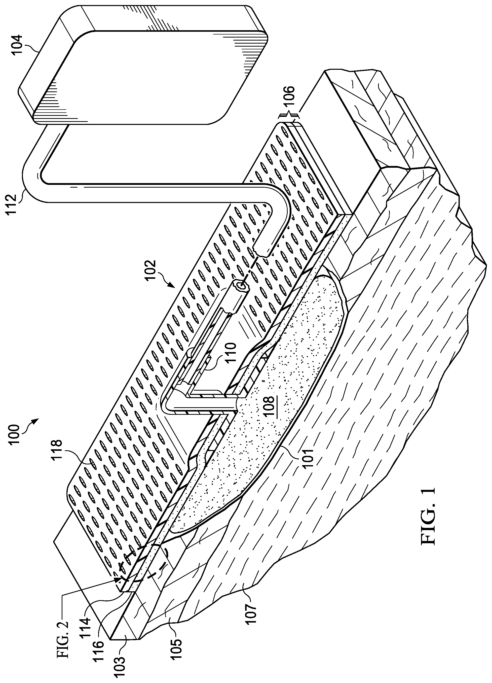
FIG. 1 is a perspective view (with a portion shown in cross section) of an illustrative embodiment of a system for treating a tissue site on a patient that employs an illustrative cover;
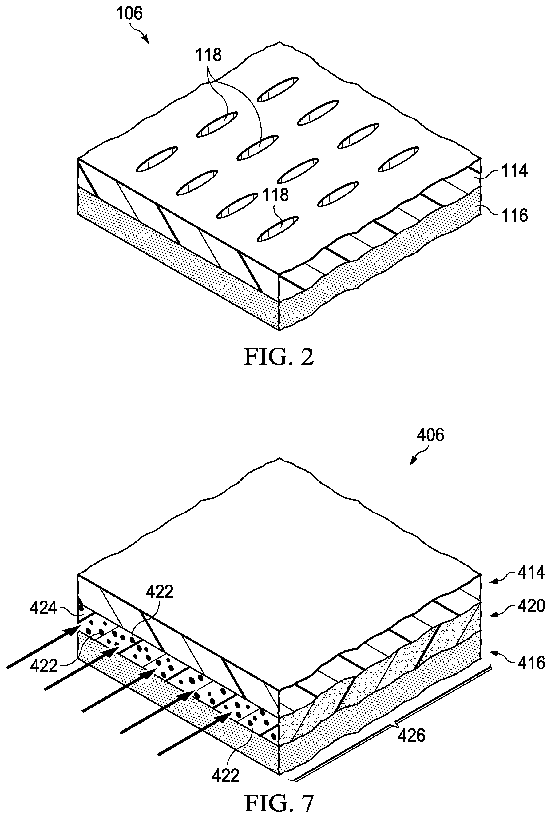
FIG. 2 is a perspective view (with a portion shown in cross section) of a portion of the illustrative cover of FIG. 1;
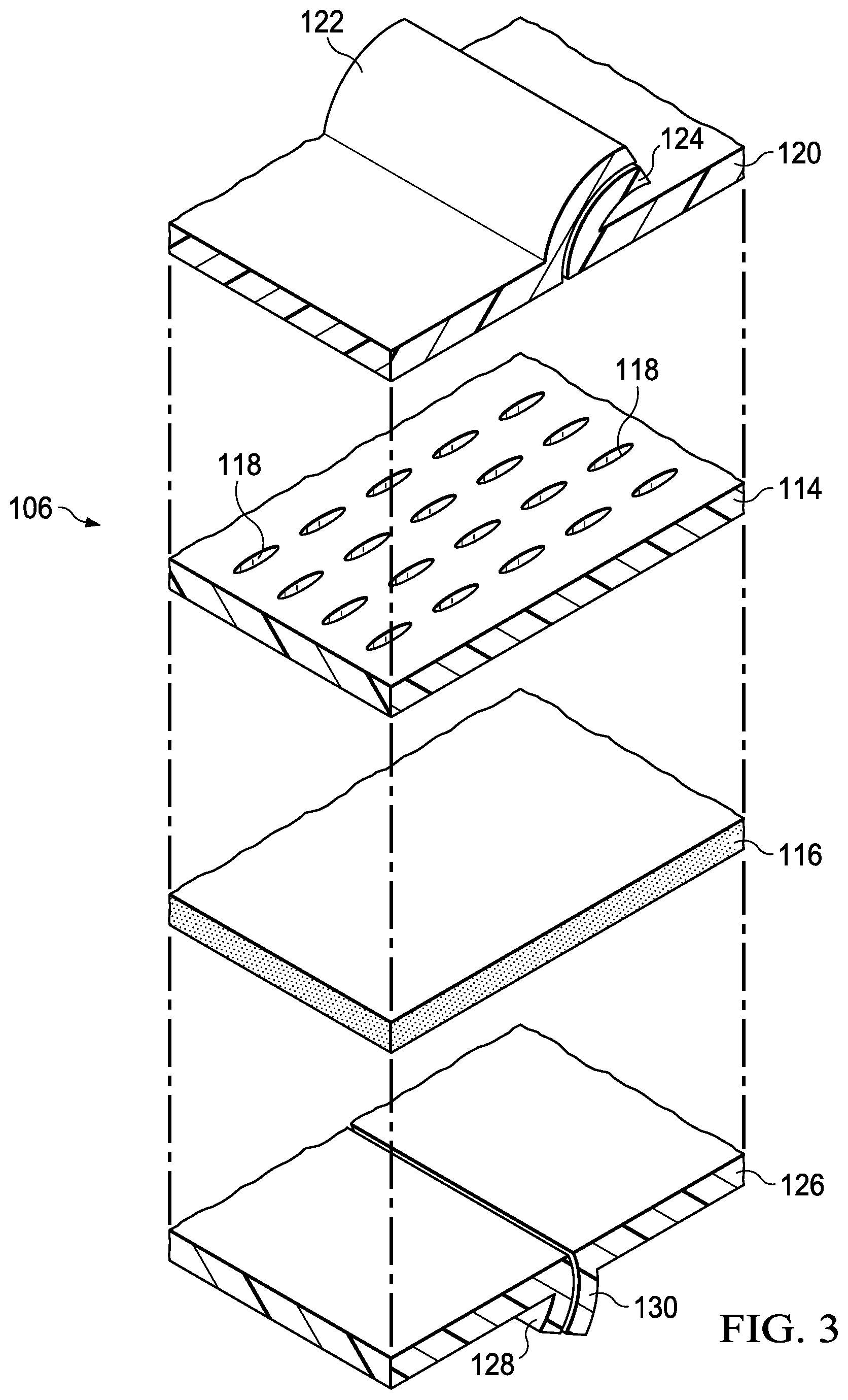
FIG. 3 is an exploded perspective view of a portion of an illustrative embodiment of the cover;
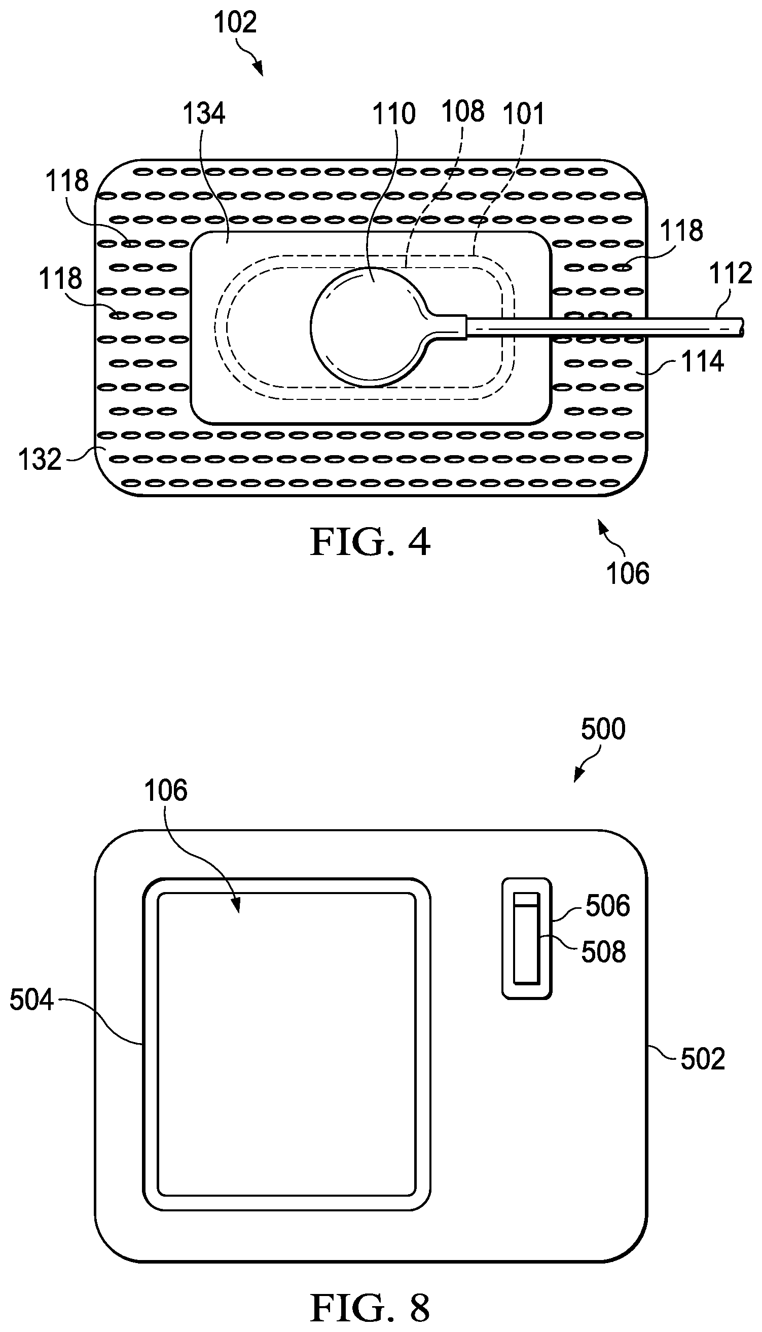
FIG. 4 is a plan view of a portion of an illustrative embodiment of a system for treating a tissue site on a patient that employs an illustrative cover;
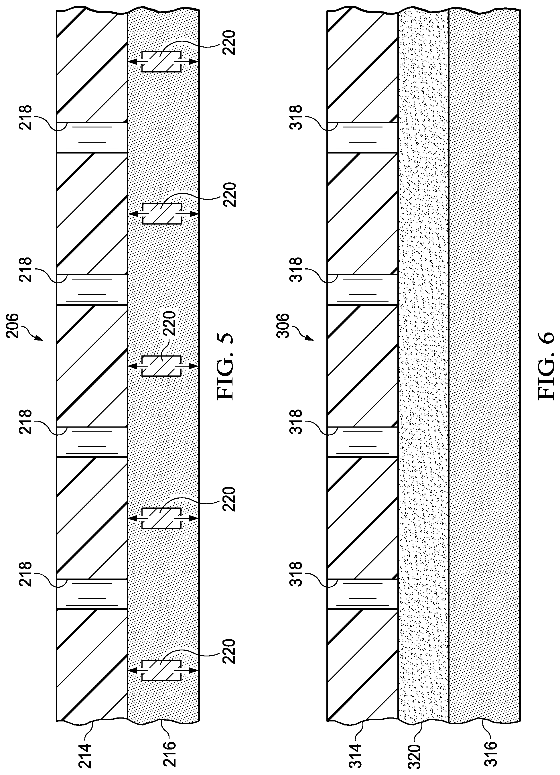
FIG. 5 is a cross-sectional view of another cover that can be used with the system of FIG. 1;
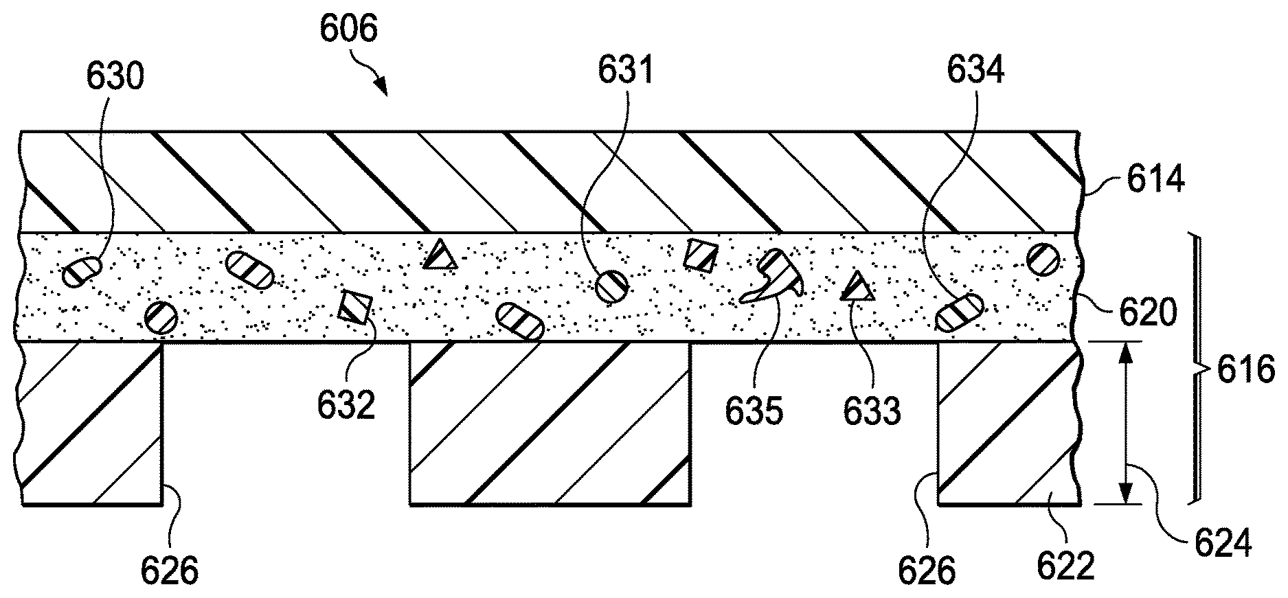
FIG. 6 is a cross-sectional view of another cover that can be used with the system of FIG. 1;
FIG. 7 is a perspective view (with a portion shown in cross section) of another cover that can be used with the system of FIG. 1;
FIG. 8 is a plan view of a kit for forming a seal over the portion of a patient's body;
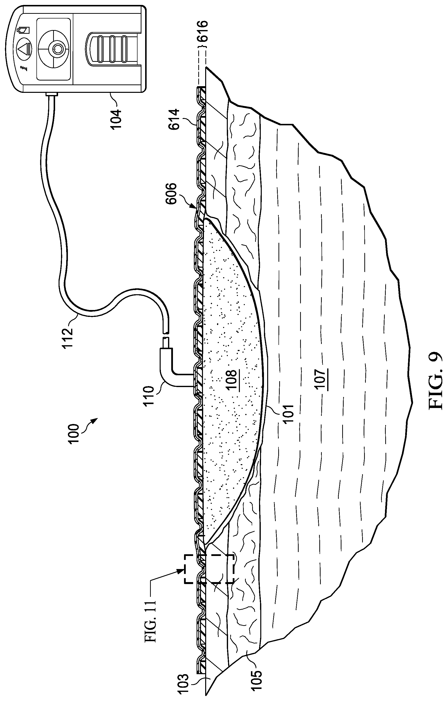
FIG. 9 is a cross-sectional view (with a portion shown in elevation) of another cover for use with the system for treating a tissue site on a patient with negative pressure of FIG. 1;
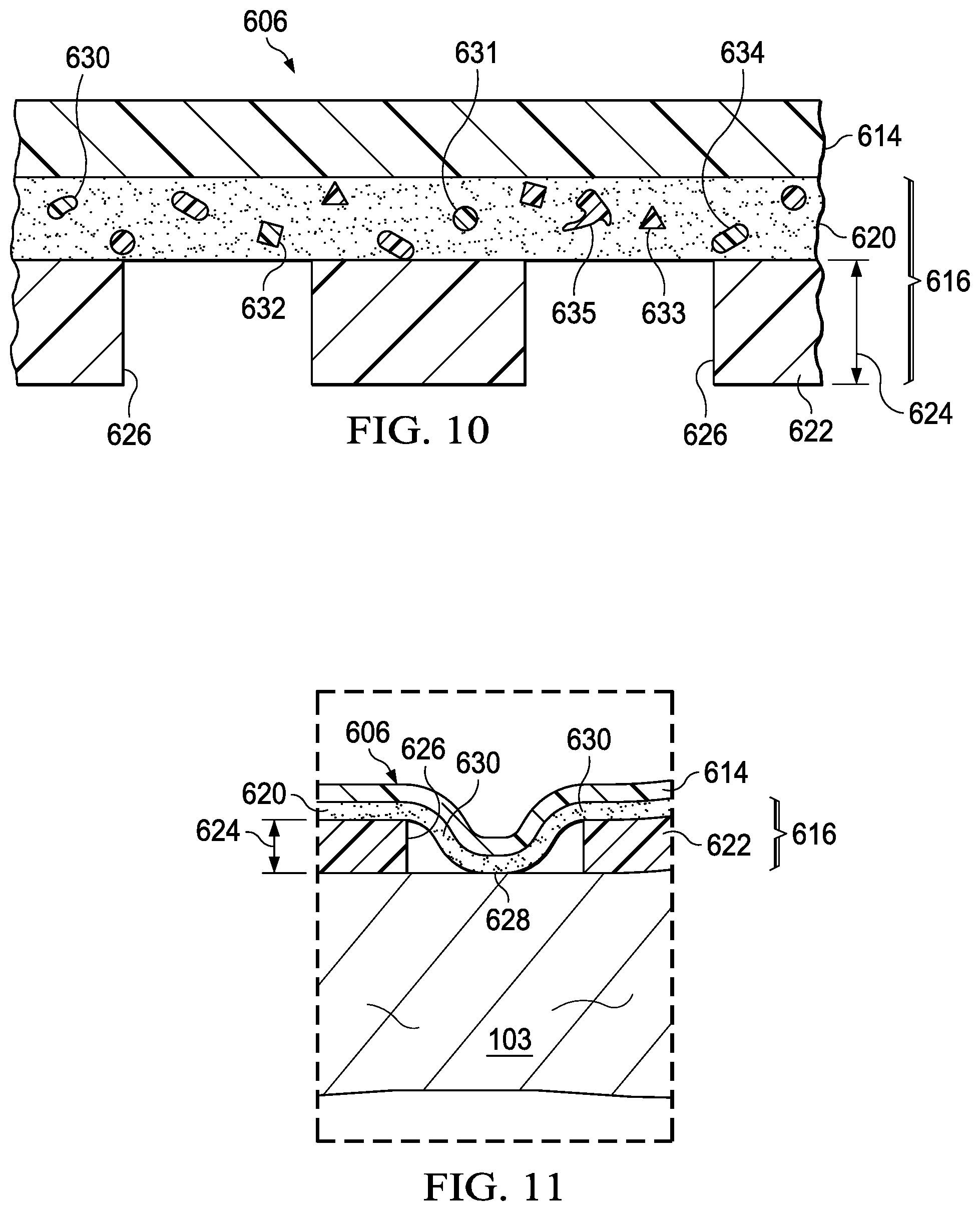
FIG. 10 is a detail in cross section of a portion of the cover of FIG. 9, illustrating additional details that may be associated with some embodiments;
FIG. 11 is a sectional view of a portion of a cover for use with the system of FIG. 9;
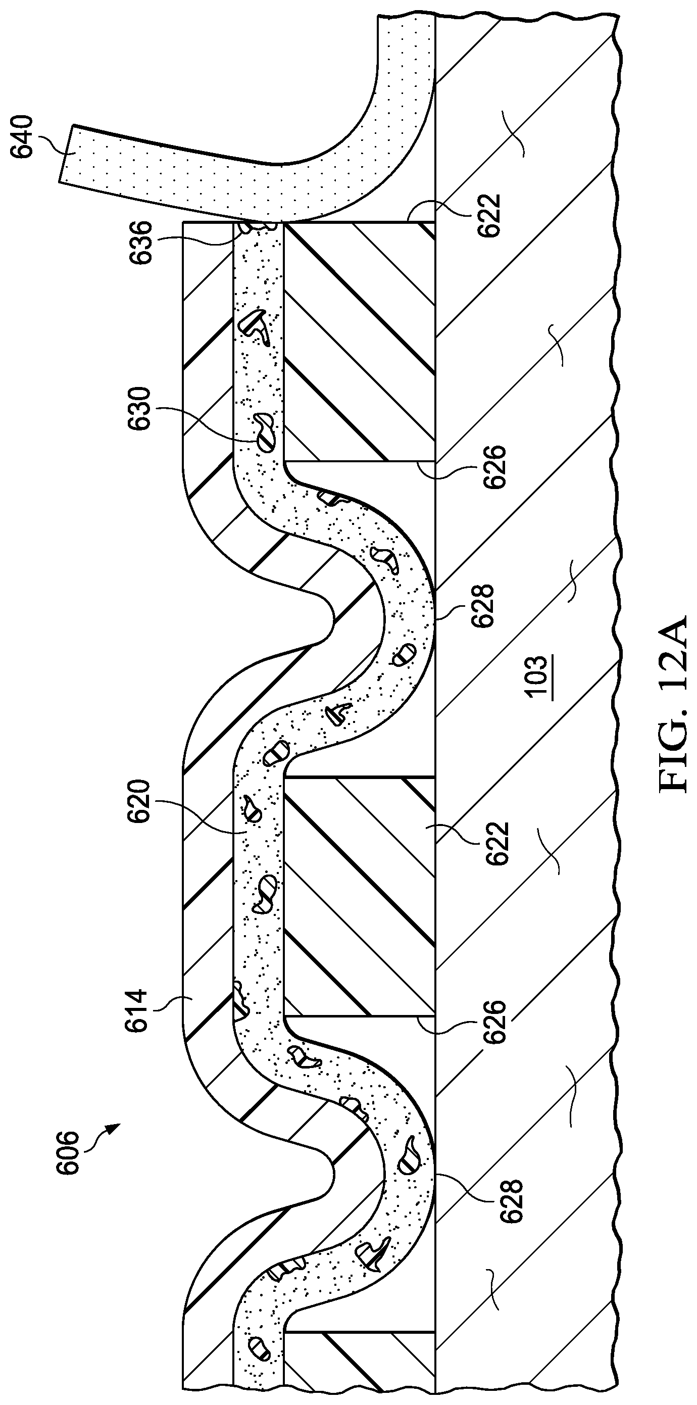
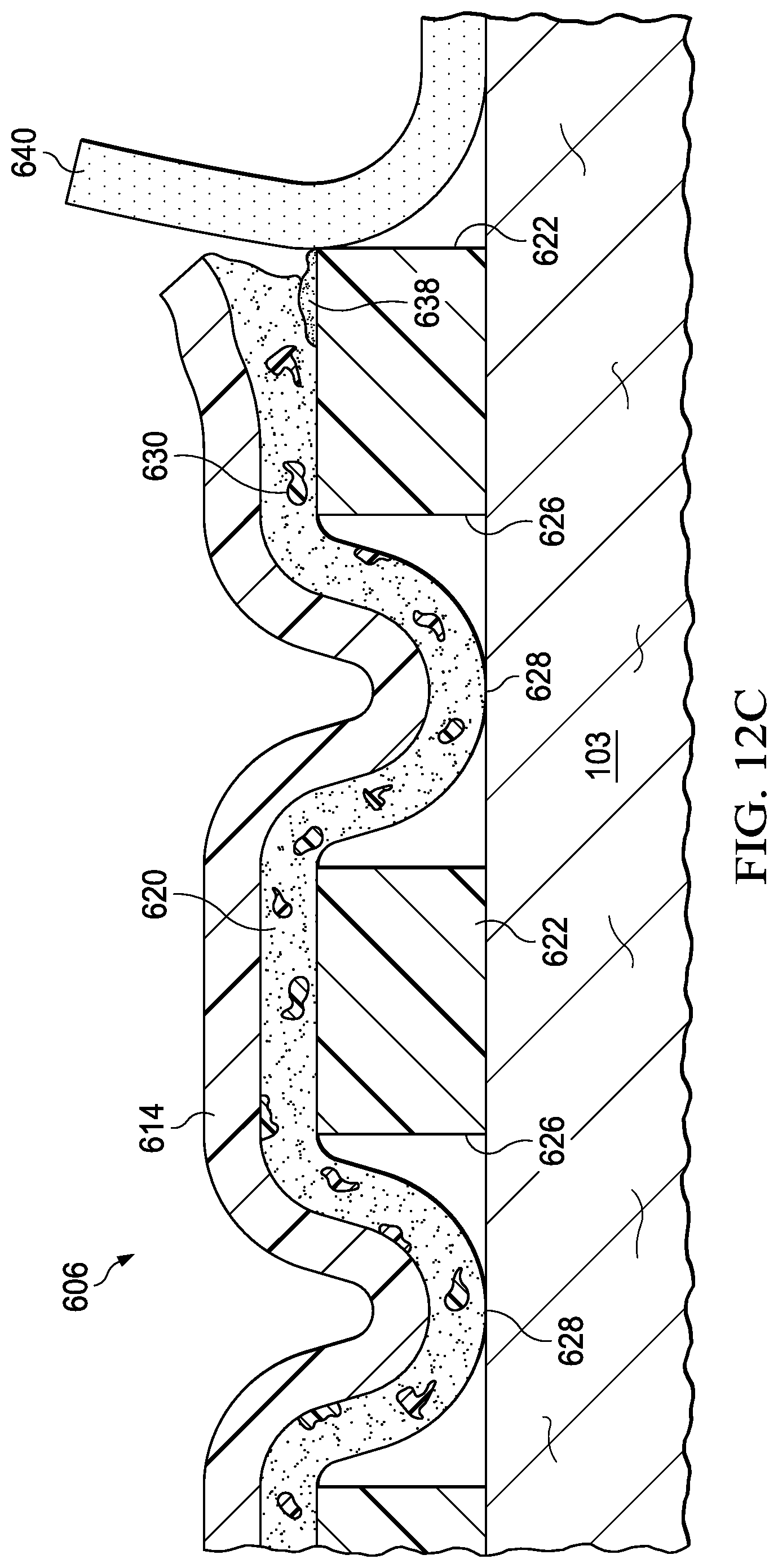
FIGS. 12A, 12B, and 12C are sectional views of a portion of the cover of FIG. 10, during removal of the cover;
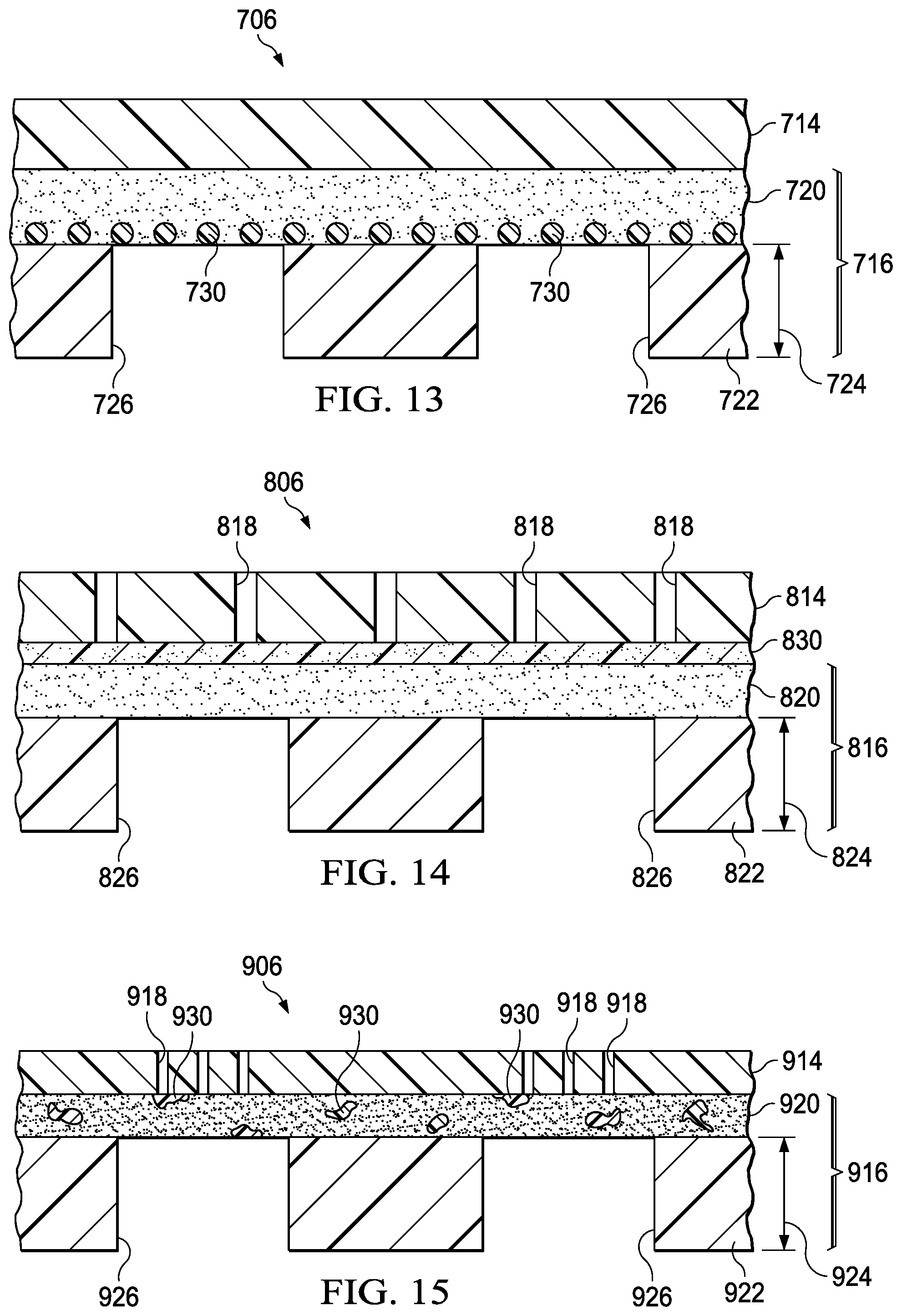
FIG. 13 is a sectional view of a portion of another cover for use with the system of FIG. 9;
FIG. 14 is a sectional view of a portion of another cover for use with the system of FIG. 9;
FIG. 15 is a sectional view of a portion of another cover for use with the system of FIG. 9;
FIG. 16 is a sectional view of a portion of the cover of FIG. 15 during use of the cover; and
FIG. 17 is a sectional view of a portion of the cover of FIG. 15 during removal of the cover.
DESCRIPTION OF EXAMPLE EMBODIMENTS
The following description of example embodiments provides information that enables a person skilled in the art to make and use the subject matter set forth in the appended claims, but may omit certain details already well-known in the art. The following detailed description is, therefore, to be taken as illustrative and not limiting.
The example embodiments may also be described herein with reference to spatial relationships between various elements or to the spatial orientation of various elements depicted in the attached drawings. In general, such relationships or orientations assume a frame of reference consistent with or relative to a patient in a position to receive treatment. However, as should be recognized by those skilled in the art, this frame of reference is merely a descriptive expedient rather than a strict prescription.
In the following detailed description of illustrative, non-limiting embodiments, reference is made to the accompanying drawings that form a part hereof. These embodiments are described in sufficient detail to enable those skilled in the art to practice the invention, and it is understood that other embodiments may be utilized and that logical, structural, mechanical, electrical, and chemical changes may be made without departing from the spirit or scope of the invention. To avoid detail not necessary to enable those skilled in the art to practice the embodiments described herein, the description may omit certain information known to those skilled in the art. The following detailed description is not to be taken in a limiting sense, and the scope of the illustrative embodiments is defined only by the appended claims.
The term "tissue site" in this context broadly refers to a wound, defect, or other treatment target located on or within tissue, including but not limited to, bone tissue, adipose tissue, muscle tissue, neural tissue, dermal tissue, vascular tissue, connective tissue, cartilage, tendons, or ligaments. A wound may include chronic, acute, traumatic, subacute, and dehisced wounds, partial-thickness burns, ulcers (such as diabetic, pressure, or venous insufficiency ulcers), flaps, and grafts, for example. The term "tissue site" may also refer to areas of any tissue that are not necessarily wounded or defective, but are instead areas in which it may be desirable to add or promote the growth of additional tissue. For example, negative pressure may be applied to a tissue site to grow additional tissue that may be harvested and transplanted.
FIG. 1 is a sectional view, with a portion shown in elevation, of a therapy system 100 that can provide therapy, such as negative-pressure therapy, to a tissue site 101. The tissue site 101 may be a wound that is through an epidermis 103, a dermis 105, and into a subcutaneous tissue 107, but any wound size, depth, or tissue may be involved.
The therapy system 100 may include a negative-pressure supply, and may include or be configured to be coupled to a distribution component, such as a dressing. In general, a distribution component may refer to any complementary or ancillary component configured to be fluidly coupled to a negative-pressure supply in a fluid path between a negative-pressure supply and a tissue site. A distribution component is preferably detachable, and may be disposable, reusable, or recyclable. For example, a dressing 102 may be fluidly coupled to a negative-pressure source 104, as illustrated in FIG. 1. A dressing may include a cover, a tissue interface, or both in some embodiments. The dressing 102, for example, may include a cover 106 and a tissue interface 108. The cover 106 may include an elastomeric film 114 and an attachment device 116. In some embodiments, the dressing 102 may be part of a sealing subsystem that can include the dressing 102 and a switching solution.
In some embodiments, a dressing interface 110 may facilitate coupling the negative-pressure source 104 to the dressing 102. For example, such a dressing interface may be a T.R.A.C..RTM. Pad or Sensa T.R.A.C..RTM. Pad available from KCI of San Antonio, Tex. The therapy system 100 may optionally include a fluid container coupled to the dressing 102 and to the negative-pressure source 104.
Additionally, the therapy system 100 may include sensors to measure operating parameters and provide feedback signals to a controller indicative of the operating parameters. As illustrated in FIG. 1, for example, the therapy system 100 may include a pressure sensor, an electric sensor, or both, coupled to the controller. The pressure sensor may also be coupled or configured to be coupled to a distribution component and to the negative-pressure source 104.
Components may be fluidly coupled to each other to provide a path for transferring fluids (i.e., liquid and/or gas) between the components. For example, components may be fluidly coupled through a fluid conductor, such as a tube 112. A "tube," as used herein, broadly includes a tube, pipe, hose, conduit, or other structure with one or more lumina adapted to convey a fluid between two ends. Typically, a tube is an elongated, cylindrical structure with some flexibility, but the geometry and rigidity may vary. In some embodiments, components may also be coupled by virtue of physical proximity, being integral to a single structure, or being formed from the same piece of material. Moreover, some fluid conductors may be molded into or otherwise integrally combined with other components. Coupling may also include mechanical, thermal, electrical, or chemical coupling (such as a chemical bond) in some contexts. For example, the tube 112 may mechanically and fluidly couple the dressing 102 to the negative-pressure source 104 in some embodiments. In general, components of the therapy system 100 may be coupled directly or indirectly. For example, the negative-pressure source 104 may be directly coupled to the tube 112, and may be indirectly coupled to the dressing 102 through the tube 112 and the dressing interface 110.
The fluid mechanics of using a negative-pressure source to reduce pressure in another component or location, such as within a sealed therapeutic environment, can be mathematically complex. However, the basic principles of fluid mechanics applicable to negative-pressure therapy and instillation are generally well-known to those skilled in the art, and the process of reducing pressure may be described illustratively herein as "delivering," "distributing," or "generating" negative pressure, for example.
In general, exudates and other fluids flow toward lower pressure along a fluid path. Thus, the term "downstream" typically implies a position in a fluid path relatively closer to a source of negative pressure or further away from a source of positive pressure. Conversely, the term "upstream" implies a position relatively further away from a source of negative pressure or closer to a source of positive pressure. Similarly, it may be convenient to describe certain features in terms of fluid "inlet" or "outlet" in such a frame of reference. This orientation is generally presumed for purposes of describing various features and components herein. However, the fluid path may also be reversed in some applications (such as by substituting a positive-pressure source for a negative-pressure source) and this descriptive convention should not be construed as a limiting convention.
"Negative pressure" generally refers to a pressure less than a local ambient pressure, such as the ambient pressure in a local environment external to a sealed therapeutic environment provided by the dressing 102. In many cases, the local ambient pressure may also be the atmospheric pressure at which a tissue site is located. Alternatively, the pressure may be less than a hydrostatic pressure associated with tissue at the tissue site. Unless otherwise indicated, values of pressure stated herein are gauge pressures. Similarly, references to increases in negative pressure typically refer to a decrease in absolute pressure, while decreases in negative pressure typically refer to an increase in absolute pressure. While the amount and nature of negative pressure applied to a tissue site may vary according to therapeutic requirements, the pressure is generally a low vacuum, also commonly referred to as a rough vacuum, between -5 mm Hg (-667 Pa) and -500 mm Hg (-66.7 kPa). Common therapeutic ranges are between -75 mm Hg (-9.9 kPa) and -300 mm Hg (-39.9 kPa).
A negative-pressure supply, such as the negative-pressure source 104, may be a reservoir of air at a negative pressure, or may be a manual or electrically-powered device that can reduce the pressure in a sealed volume, such as a vacuum pump, a suction pump, a wall suction port available at many healthcare facilities, or a micro-pump, for example. A negative-pressure supply may be housed within or used in conjunction with other components, such as sensors, processing units, alarm indicators, memory, databases, software, display devices, or user interfaces that further facilitate therapy. For example, the negative-pressure source 104 may be combined with a controller and other components into a therapy unit. A negative-pressure supply may also have one or more supply ports configured to facilitate coupling and de-coupling the negative-pressure supply to one or more distribution components. In another illustrative embodiment, a negative-pressure supply may be a micro-pump. A micro-pump may be a pump sized to be coupled to a cover, such as the cover 106.
A controller may be a microprocessor or computer programmed to operate one or more components of the therapy system 100, such as the negative-pressure source 104. In some embodiments, for example, a controller may be a microcontroller, which generally comprises an integrated circuit containing a processor core and a memory programmed to directly or indirectly control one or more operating parameters of the therapy system 100. Operating parameters may include the power applied to the negative-pressure source 104, the pressure generated by the negative-pressure source 104, or the pressure distributed to the tissue interface 108, for example. A controller is also preferably configured to receive one or more input signals, such as a feedback signal, and programmed to modify one or more operating parameters based on the input signals.
Sensors are generally known in the art as any apparatus operable to detect or measure a physical phenomenon or property, and generally provide a signal indicative of the phenomenon or property that is detected or measured. For example, a pressure sensor and an electric sensor may be configured to measure one or more operating parameters of the therapy system 100. In some embodiments, a pressure sensor may be a transducer configured to measure pressure in a pneumatic pathway and convert the measurement to a signal indicative of the pressure measured. In some embodiments, for example, a pressure sensor may be a piezoresistive strain gauge. An electric sensor may optionally measure operating parameters of the negative-pressure source 104, such as the voltage or current, in some embodiments. Preferably, the signals from sensors are suitable as input signals to a controller, but some signal conditioning may be appropriate in some embodiments. For example, the signal may need to be filtered or amplified before it can be processed by a controller. Typically, the signal is an electrical signal, but may be represented in other forms, such as an optical signal.
A container is representative of a container, canister, pouch, or other storage component, which can be used to manage exudates and other fluids withdrawn from a tissue site. In many environments, a rigid container may be preferred or required for collecting, storing, and disposing of fluids. In other environments, fluids may be properly disposed of without rigid container storage, and a re-usable container could reduce waste and costs associated with negative-pressure therapy.
The tissue interface 108 can be generally adapted to contact a tissue site. The tissue interface 108 may be partially or fully in contact with the tissue site. If the tissue site is a wound, for example, the tissue interface 108 may partially or completely fill the wound, or may be placed over the wound. The tissue interface 108 may take many forms, and may have many sizes, shapes, or thicknesses depending on a variety of factors, such as the type of treatment being implemented or the nature and size of a tissue site. For example, the size and shape of the tissue interface 108 may be adapted to the contours of deep and irregular shaped tissue sites. Moreover, any or all of the surfaces of the tissue interface 108 may have projections or an uneven, course, or jagged profile that can induce strains and stresses on a tissue site, which can promote granulation at the tissue site.
In some embodiments, the tissue interface 108 may be a manifold. A "manifold" in this context generally includes any substance or structure providing a plurality of pathways adapted to collect or distribute fluid across a tissue site under pressure. For example, a manifold may be adapted to receive negative pressure from a source and distribute negative pressure through multiple apertures across a tissue site, which may have the effect of collecting fluid from across a tissue site and drawing the fluid toward the source. In some embodiments, the fluid path may be reversed or a secondary fluid path may be provided to facilitate delivering fluid across a tissue site.
In some illustrative embodiments, the pathways of a manifold may be interconnected to improve distribution or collection of fluids across a tissue site. In some illustrative embodiments, a manifold may be a porous foam material having interconnected cells or pores. For example, cellular foam, open-cell foam, reticulated foam, porous tissue collections, and other porous material such as gauze or felted mat generally include pores, edges, and/or walls adapted to form interconnected fluid channels. Liquids, gels, and other foams may also include or be cured to include apertures and fluid pathways. In some embodiments, a manifold may additionally or alternatively comprise projections that form interconnected fluid pathways. For example, a manifold may be molded to provide surface projections that define interconnected fluid pathways.
The average pore size of a foam may vary according to needs of a prescribed therapy. For example, the tissue interface 108 may be a foam having pore sizes in a range of 400-600 microns. The tensile strength of the tissue interface 108 may also vary according to needs of a prescribed therapy. For example, the tensile strength of a foam may be increased for instillation of topical treatment solutions. In one non-limiting example, the tissue interface 108 may be an open-cell, reticulated polyurethane foam such as GranuFoam.RTM. dressing or VeraFlo.RTM. foam, both available from Kinetic Concepts, Inc. of San Antonio, Tex.
The tissue interface 108 may be either hydrophobic or hydrophilic. In an example in which the tissue interface 108 may be hydrophilic, the tissue interface 108 may also wick fluid away from a tissue site, while continuing to distribute negative pressure to the tissue site. The wicking properties of the tissue interface 108 may draw fluid away from a tissue site by capillary flow or other wicking mechanisms. An example of a hydrophilic foam is a polyvinyl alcohol, open-cell foam such as V.A.C. WhiteFoam.RTM. dressing available from Kinetic Concepts, Inc. of San Antonio, Tex. Other hydrophilic foams may include those made from polyether. Other foams that may exhibit hydrophilic characteristics include hydrophobic foams that have been treated or coated to provide hydrophilicity.
The tissue interface 108 may further promote granulation at a tissue site if pressure within the sealed therapeutic environment is reduced. For example, any or all of the surfaces of the tissue interface 108 may have an uneven, coarse, or jagged profile that can induce microstrains and stresses at a tissue site if negative pressure is applied through the tissue interface 108.
In some embodiments, the tissue interface 108 may be constructed from bioresorbable materials. Suitable bioresorbable materials may include, without limitation, a polymeric blend of polylactic acid (PLA) and polyglycolic acid (PGA). The polymeric blend may also include, without limitation, polycarbonates, polyfumarates, and capralactones. The tissue interface 108 may further serve as a scaffold for new cell-growth, or a scaffold material may be used in conjunction with the tissue interface 108 to promote cell-growth. A scaffold is generally a substance or structure used to enhance or promote the growth of cells or formation of tissue, such as a three-dimensional porous structure that provides a template for cell growth. Illustrative examples of scaffold materials include calcium phosphate, collagen, PLA/PGA, coral hydroxy apatites, carbonates, or processed allograft materials.
The provision of negative pressure therapy with negative pressure therapy systems, such as the therapy system 100, is increasingly being performed with smaller therapy devices that use battery power rather than a connection to an electrical outlet. Use of battery power decreases the total power supply available to a therapy device. As a result, power drains that would be considered negligible in a device powered through an electrical outlet connection may significantly reduce the ability of the therapy device to provide therapy. A power drain refers to operation of the therapy device that requires use of electrical power, for example, operation of a pump to generate negative pressure. Power drains may be caused by low-level dressing leaks, for example. A low-level dressing leak can drain power from a battery of a therapy device by repeatedly triggering operation of the therapy device to maintain the necessary negative pressure at the tissue site. These power drains shorten the useful life of the therapy device before disposal of the therapy device, recharge of the battery, or battery replacement is required. Leak detection techniques may help to identify some leaks that may then be sealed by the user; however, low level leaks will challenge the most sensitive leak detection systems and may often go undetected.
Low level dressing leaks may occur between the cover and the epidermis surrounding a tissue site when the cover fails to completely seal to the epidermis. Covers are a balance between the strength of the adhesive required to enable the cover to seal against leaks and the pain which may result when the cover is removed. A bonding adhesive may be better for sealing, but the adhesive strength would cause significantly more discomfort upon cover removal. In addition, removing a cover with a bonding adhesive may cause significant damage to patients having delicate or damaged skin.
A cover that has a sealing adhesive can fill gaps between the drape and the epidermis to limit leaks and can be easy to remove with low discomfort to the patient. Various sealing, gap-filling adhesives, such as silicone, hydrocolloids, and hydrogels, have been tried but each has drawbacks. For example, hydrogel adhesives are usually low tack and prone to swelling, creep, and mobility when used with fluid systems. In another example, silicone adhesives can fill gaps and seal, but are not breathable and may lose the necessary mechanical bonding strength as the silicone adhesives interact with moisture during use. To counter these problems, silicone adhesives often require additional materials to secure the silicone adhesive to the patient. For example, a low leak cover may be formed from two adhesive layers: a thick sealing adhesive, perhaps in the shape of a gasket or ring, and a thinner bonding adhesive layer used to keep the sealing adhesive in place. The thinner bonding adhesive may be applied as cover strips, or combined with the thicker sealing adhesive as an outer border. Low-leak covers constructed in this way can be more complex than a cover using a single adhesive, increasing the complexity of manipulation and operation.
The therapy system 100 can address these problems by providing a cover having a bonding adhesive with a high bond strength, and switchable characteristics. For example, the bonding adhesive may have a plurality of polymer particles disposed in the bonding adhesive. If the cover is to be removed, a switching solution can be applied to the cover to dissolve the polymer particles, causing the bonding adhesive to decrease in bond strength. In this manner, the cover can provide a seal against a tissue site that may be highly exudating or in a difficult to seal area, without causing additional trauma to the tissue site. The therapy system 100 can also address these problems by providing a cover having a bonding adhesive with a high bond strength paired with a sealing adhesive having good sealing characteristics. In some embodiments, the bonding adhesive can also be switchable, permitting the bonding adhesive to have a first bond strength during use of the cover that can be transitioned to a second bond strength if the cover is to be removed.
In some embodiments, the cover 106 may provide a bacterial barrier and protection from physical trauma. The cover 106 can be used as a component of the dressing 102 during the provision of negative-pressure therapy and as a component of the dressing 102 without the provision of negative-pressure therapy. The cover 106 may also be constructed from a material that can reduce evaporative losses and provide a fluid seal between two components or two environments, such as between a therapeutic environment and a local external environment. The cover 106 may be a film layer or barrier layer, such as the elastomeric film 114, or a membrane that can provide a seal adequate to maintain a negative pressure at a tissue site for a given negative-pressure source. Elastomeric material generally refers to a polymeric material that has rubber-like properties. More specifically, most elastomers have ultimate elongations greater than 100% and a significant amount of resilience. The resilience of a material refers to the ability of the material to recover from an elastic deformation. Examples of elastomers include, but are not limited to, natural rubbers, polyisoprene, styrene butadiene rubber, chloroprene rubber, polybutadiene, nitrile rubber, butyl rubber, ethylene propylene rubber, ethylene propylene diene monomer, chlorosulfonated polyethylene, polysulfide rubber, polyurethane (PU), EVA film, co-polyester, and silicones. Examples of the elastomeric film 114 can include a silicone drape, a 3M Tegaderm.RTM. drape, or a polyurethane (PU) drape such as one available from Avery Dennison Corporation of Pasadena, Calif.
The cover 106 may have a high moisture-vapor transmission rate (MVTR). MVTR represents the amount of moisture that can pass through a material in a given period of time. For example, the cover 106 may have an MVTR greater than about 300 g/m.sup.2/24 hours or, more typically, greater than about 1000 g/m.sup.2/24 hours or more. In some example embodiments, the elastomeric film 114 may be a polymer drape, such as a polyurethane film, that is permeable to water vapor but impermeable to liquid. Such drapes typically have a thickness in the range of 25-50 microns. For permeable materials, the permeability generally should be low enough that a desired negative pressure may be maintained.
Additional examples of suitable examples of the elastomeric film 114 include one or more of the following: hydrophilic polyurethanes, cellulosics, hydrophilic polyamides, polyvinyl alcohol, polyvinyl pyrrolidone, hydrophilic silicone polymers, hydrophilic acrylics, hydrophilic silicone elastomers and copolymers of these. As one specific, illustrative, non-limiting embodiment, the elastomeric film 114 may be a breathable cast mat polyurethane film sold under the name INSPIRE 2301 from Exopack Advanced Coatings of Wrexham, United Kingdom, having an MVTR (inverted cup technique) of 14500-14600 g/m.sup.2/24 hours. The elastomeric film 114 may have various thicknesses, such as about 10 microns to about 100 microns (.mu.m), e.g., 15, 20, 30, 40, 50, 60, 70, 80, 90, 100 microns or any number in the stated range.
The attachment device 116 may be used to attach the cover 106 to an attachment surface, such as undamaged epidermis, a gasket, or another cover. The attachment device 116 may take many forms. For example, an attachment device may be a medically-acceptable, pressure-sensitive adhesive that extends about a periphery, a portion, or an entire sealing member. In some embodiments, the attachment device 116 may be an acrylic adhesive having a coating weight between 25-65 grams per square meter (gsm) that can be coated onto some or all of the elastomeric film 114. Thicker adhesives, or combinations of adhesives, may be applied in some embodiments to improve the seal and reduce leaks. Other example embodiments of an attachment device may include a double-sided tape, paste, hydrocolloid, hydrogel, silicone gel, or organogel.
The attachment device 116 may have a bond strength one to two times stronger than adhesives used on most covers. For example, without limitation, one cover, for example, MED1827A by Avery, has a bond strength of about 1.44N/cm to a polyethene substrate using a 90 degree angle test according to American Society for Testing and Materials ("ASTM") standard ASTM D3330. Whereas, according to one illustrative embodiment, the cover 106 may have a bond strength in the range of greater than about 1.44N/cm to about 2.88N/cm under similar testing conditions. The attachment device 116 typically has a thickness in the range of about 0.3 mm to about 1.5 mm. The attachment device 116 may be formed from an acrylic adhesive or another adhesive. The attachment device 116 can be considered flowable, permitting the attachment device 116 to fill any cracks or crevices in the epidermis 103 adjacent the tissue site 101 to form a strong fluid seal and maintain that seal when negative pressure is applied to the sealed space. An adhesive that is flowable may readily move into small surface contours, such as grooves on a surface of the epidermis or an edge of a cover. Adhesives that flow and provide close contact between objects and form a fluid-tight seal. In some embodiments, an adhesive that is flowable may have a value between about 20 mm and about 25 mm in a cone penetration test conducted using a 60 second dwell time and a 62.5 g cone according to International Organization for Standardization (ISO) DIN ISO 2137.
The attachment device 116 may be switchable. For example, the attachment device 116 may have a first bond strength and, after application of an external stimulus, a second bond strength. For example, the attachment device 116 may have the first bond strength, but after interaction with or exposure to a switching solution, the attachment device 116 may have a second bond strength. In some embodiments, interaction with the switching solution may reduce the bond strength of the attachment device 116 so that the second bond strength is less than the first bond strength.
The switching solution may be a release solution formed from one or more of the following: alcohols, such as ethanol, methanol, propyl alcohols, such as isopropyl alcohol, isopropanol, and other alcohols such as butanols, esters such as butyl ethanoate (acetate), ketones, such as propanone (acetone), natural oils such as linseed, soyer, blends of all these materials with each other, and may also be blended with water. In some embodiments, the switching solution may be a mixture of water and a weak acid or a mixture of water and one or more of ethanol and isopropanol. The switching solution may contain additional components such as a local pain killer or analgesic, for example, lidocaine, prilocaine, bupivacaine, or mixtures of these, or another suitable substance. The switching solution may be kept in a bottle, vial, pouch, sealed wipe, or other convenient storage or delivery means.
The switching solution can reduce the bond strength of the attachment device 116 from the first bond strength to the second bond strength. For example, if the attachment device 116 has an initial bond strength of A.sub.1, after application of the switching solution, the attachment device 116 may have a bond strength, A.sub.2. In some embodiments, the bond strength A.sub.2 is less than the bond strength A.sub.1, for example, A.sub.2<A.sub.1. The bond strength A.sub.2 after application of the switching solution may be less than about 70% of the original bond strength, 70% A.sub.1, or even less, for example, 60% A.sub.1, 50% A.sub.1, 40 A.sub.1, 30% A.sub.1, 20% A.sub.1, 10% A.sub.1, or 0% A.sub.1. Many permutations are possible, but in one embodiment, the cover 106 has twice the bond strength of a traditional drape, but at removal has only half or less than half of the bond strength of a traditional drape.
FIG. 2 is a perspective view (with a portion shown in cross section) of a portion of the cover 106 of FIG. 1. The cover 106 includes the elastomeric film 114 and the attachment device 116. In some embodiments, the elastomeric film 114 may have a plurality of perforations 118 extending through the elastomeric film 114. The plurality of perforations 118 may be apertures having material removed from the elastomeric film 114 or may be slits having an opening but not material removal. In one illustrative embodiment, each perforation 118 of the plurality of perforations 118 creates an opening having an average effective diameter in the range of about 0.05 mm to about 0.40 mm. An effective diameter is a diameter of a circular area having the same surface area as a corresponding non-circular area. In another illustrative embodiment, a portion of the material forming the elastomeric film 114 may be removed to form each perforation 118 of the plurality of perforations 118. The total surface area of the removed portion of material may average between about 0.2% to about 13% of the total surface area of the elastomeric film 114.
The plurality of perforations 118 may cover all of the elastomeric film 114 or a portion of the elastomeric film 114. The plurality of perforations 118 may have a pitch between adjacent perforations 118. The pitch is a measurement of the repeated distance between adjacent perforations 118 having translational symmetry. For example, if a surface of the elastomeric film 114 is described by two orthogonal lines, the pitch describes the distance between adjacent perforations 118 parallel to the two orthogonal lines. The pitch of the plurality of perforations 118 is typically between about two times and about six times a thickness of the attachment device 116. For example, the attachment device 116 may have a thickness of about 0.5 mm and a pitch of the plurality of perforations 118 in the elastomeric film 114 may be between about 1.0 mm and about 3.0 mm. The pitch can vary between the two orthogonal directions, and the pitch can be non-uniform in each direction. In some embodiments, the pitch may have gaps in the pattern of perforations 118 described by the pitch.
The attachment device 116 may be coated onto a side of the elastomeric film 114. The attachment device 116 may generally be continuous and coextensive with the elastomeric film 114. As a result, the plurality of perforations 118 may be covered by the attachment device 116. Covering of the plurality of perforations 118 by the attachment device 116 may prevent leaks through the plurality of perforations 118
The plurality of perforations 118 may expose the attachment device 116 from an un-coated side of the elastomeric film 114. Exposure of the attachment device 116 permits the switching solution to be applied to the attachment device 116 through the elastomeric film 114. In some embodiments, the size and distribution of the plurality of perforations 118 can be used to control the rate of interaction between the switching solution and the attachment device 116.
If no material is removed to form the perforations 118, the perforations 118 may be slits such as half-moon slits. As slits, the plurality of perforations 118 act as small valves, and act to minimize exposure of the attachment device 116 to the un-coated side of the elastomeric film 114. If the drape material is removed to form the plurality of perforations 118, the attachment device 116 may extend through the perforations 118 and causes a tackiness to be experienced on an un-coated side of the elastomeric film 114. In this case, a release liner be applied and left in place to cover the perforations 118 on a side of the elastomeric film 114 until removal of the cover 106 is desired. Alternatively, a powder or sealing agent may be applied on a side of the elastomeric film 114.
In some embodiments, the plurality of perforations 118 may be formed by a user during use of the cover 106. For example, a hand tool may be provided with the cover 106. If a user desires to remove the cover 106 from a tissue site 101, the hand tool can be used to form the a plurality of perforations 118. For example, the hand tool may be a device having a roller with one or more scalpets disposed on the roller. The roller may be rolled across the elastomeric film 114, permitting the scalpets to form the plurality of perforations 118 in the elastomeric film 114. After formation of the plurality of perforations, the switching solution is applied over the perforations 118 to transition the attachment device 116 from the first bond strength to the second bond strength.
FIG. 3 is an exploded perspective view of a portion of the cover 106, illustrating additional details that may be associated with some embodiments of the therapy system 100. A first side of the elastomeric film 114 may be covered by a first release liner 120. The first release liner 120 may be a material that seals the surface of or provides additional handling rigidity to the elastomeric film 114. The first release liner 120 may also be a material that is removable. The first release liner 120 may comprise one or more of the following: a polyurethane film, high density polyethylene, a high-MVTR film, polymers such as acrylic copolymers, polyvinyl acetate, polyether block amide copolymers (PEBAX), polyvinyl alcohol and copolymers, polyamide, polyvinylchloride, or polyvinylidene chloride. In some embodiments, the first release liner 120 may be a two-part member having a first gripping portion 122 and a second gripping portion 124 to facilitate removal. The first release liner 120 may be retained only during deployment of the elastomeric film 114 and then removed. Alternatively, the first release liner 120 may remain in place covering the plurality of perforations 118 until removal of the elastomeric film 114 from the tissue site 101 is desired. In this latter situation, the first release liner 120 prevents accidental exposure of the attachment device 116 to a switching solution through the plurality of perforations 118.
A second release liner 126 may be used to cover a side of the attachment device 116 opposite the elastomeric film 114. The second release liner 126 may be similar to and operate as described above with respect to the first release liner 120. The second release liner 126 can be removed before the attachment device 116 is deployed against the epidermis 103 adjacent the tissue site 101. The second release liner 126 may include a first gripping member 128 and a second gripping member 130 to facilitate removal of the second release liner 126 from the attachment device 116.
The cover 106 may be formed in numerous ways. According to one illustrative embodiment, the elastomeric film 114 is formed from a drape material. The plurality of perforations 118 are then formed through the elastomeric film 114 by punching, cutting, or drilling, for example. The attachment device 116 can be applied to a side of the elastomeric film 114. The first release liner 120 can be applied to a side of the elastomeric film 114 that is opposite the attachment device 116. The second release liner 126 can be applied to a side of the attachment device 116 that is opposite the elastomeric film 114.
In operation, the tissue interface 108 is deployed adjacent to the tissue site 101. The cover 106 is deployed over the tissue interface 108 and a portion of the epidermis 103 adjacent to the tissue site 101 to create a sealed therapeutic environment. If not already applied, the dressing interface 110 is applied to provide fluid communication from a point exterior of the cover 106 to the sealed therapeutic environment. The tube 112 is fluidly coupled between the dressing interface 110 and the negative-pressure source 104. The negative-pressure source 104 is activated and fluid is drawn from the sealed therapeutic environment through the tissue interface 108 to generate a negative pressure. After a desired treatment time has passed, the cover 106 can be removed.
The cover 106 can be removed by removing the first release liner 120, if applicable, and applying the switching solution on the cover 106. The switching solution travels through the plurality of perforations 118 in the elastomeric film 114 and wets the attachment device 116. Wetting the attachment device 116 with the switching solution can cause the bond strength of the attachment device 116 to transition from the first bond strength to the second bond strength. The cover 106 is then removed from the tissue site 101 and the epidermis 103.
FIG. 4 is a plan view of a portion of the dressing 102, illustrating another cover 106 that can be used with the therapy system 100 of FIG. 1. As shown in FIG. 4, the cover 106 is disposed over the tissue site 101 and the tissue interface 108. The dressing interface 110 may be coupled to the cover 106, and the tube 112 may be coupled between the dressing interface 110 and the negative-pressure source 104. The cover 106 of FIG. 4 is similar to and includes the features of the cover 106 of FIG. 1, FIG. 2, and FIG. 3. The cover 106 of FIG. 4 can include a peripheral portion 132 and a central portion 134. The peripheral portion 132 is an outer band on the elastomeric film 114 that is sized to be exclusively or nearly exclusively over the epidermis 103 adjacent the tissue site 101. The central portion 134 of the elastomeric film 114 is over the tissue site 101. The plurality of perforations 118 are formed through the peripheral portion 132 of the elastomeric film 114, and the central portion 134 does not have the perforations 118. The attachment device 116 (not shown) is applied to the elastomeric film 114. In some embodiments, the attachment device 116 may have a first bond strength on the peripheral portion 132 of the elastomeric film 114, and a second bond strength on the central portion 134. The first bond strength of the attachment device 116 on the peripheral portion 132 may be greater than the second bond strength of the attachment device 116 on the central portion 134.
In some illustrative embodiments, the perforations 118 may be located only in certain places or may be located in key places or concentrated in certain places for different effects. For example, as explained in connection with FIG. 4, the perforations 118 may only be in the peripheral portion 132. In addition, the perforations 118 may also be concentrated to form tear lines or tear patterns. The tear patterns or tear lines allow the cover 106 to be torn by hand along the tear line or tear pattern. In this way, the cover 106 may be sized by hand without separate tools. In some embodiments, the perforations 118 may be located, for example, over a joint, to facilitate stretching of the cover 106.
FIG. 5 is a cross-sectional view of a cover 206, illustrating additional details that may be used with some embodiments of the therapy system 100 of FIG. 1. The cover 206 can include an elastomeric film 214, an attachment device 216, and a plurality of perforations 218. The elastomeric film 214, the attachment device 216, and the plurality of perforations 218 may be similar to and operate as described above with respect to the elastomeric film 114, the attachment device 116, and the plurality of perforations 118. The cover 206 can also include polymer particles such as a plurality of expansion members 220. The plurality of expansion members 220 can be disposed in the attachment device 216. In some embodiments, the expansion members 220 can be a compressed foam, such as a polyvinyl acetate foam. The foam can be compressed and cooled below a transition temperature to fix a set of the foam. The set may be a compressed state of the foam that can be released in response to exposures of the compressed foam with a plasticizer. A plasticizer may be a substance or external force, such as the switching solution, that can cause the compressed foam to plasticize and release the set of the foam. In some embodiments, the expansion members 220 can be set to expand preferentially in a particular direction. For example, each expansion member 220 may be compressed in a first direction and uncompressed in a second direction. If the expansion member 220 interacts with the plasticizer, such as the switching solution, the foam that was compressed in the first direction may expand, while the foam that was not compressed in the second direct may remain static. The expansion members 220 can be disposed in the attachment device 216 so that the first direction is oriented in a desired direction of expansion. For example, the expansion members 220 can be configured to expand primarily perpendicularly to a surface of the elastomeric film 214. If activated by the plasticizer, the expansion members 220 can expand in the first direction, perpendicular to a surface of the elastomeric film 214.
The expansion members 220 may also contain a foaming agent, such as a bicarbonate salt. If using a bicarbonate salt, the switching solution may include water and a weak acid (such as citric acid). If the water and the weak acid come into contact with the bicarbonate salt, carbon dioxide gas is released. Release of carbon disoxide gas into the attachment device 216 can provide an expanding force.
In operation, if the cover 206 is to be removed from a tissue site, the switching solution can be applied to the attachment device 216 through the plurality of perforations 218 in the elastomeric film 214. The switching solution may interact with the expansion members 220, causing the expansion members 220 to expand. As the expansion members 220 expand at least partially perpendicularly to the epidermis 103 adjacent the tissue site 101, the elastomeric film 214 may lift away from the attachment device 216. The switching solution may also weaken the attachment device 216. Lifting of the elastomeric film 214 from the attachment device 216 and weakening of the attachment device 216 facilitates removal of the cover 206 from the tissue site 101.
FIG. 6 is a cross-sectional view of a cover 306, illustrating additional details that may be used with some embodiments of the therapy system 100 of FIG. 1. The cover 306 is analogous in most respects to the cover 106 of FIG. 1, FIG. 2, and FIG. 3, and includes an elastomeric film 314, an attachment device 316, and a plurality of perforations 318. The elastomeric film 314, the attachment device 316, and the plurality of perforations 318 may be similar to and operate as described above with respect to the elastomeric film 114, the attachment device 116, and the plurality of perforations 118 of FIG. 1, FIG. 2, and FIG. 3. The cover 306 can include a soluble layer 320. The soluble layer 320 can be disposed between the elastomeric film 314 and the attachment device 316. A first surface of the soluble layer 320 can contact a surface of the elastomeric film 314, and a second surface of the soluble layer 320 that is opposite the first surface can contact a surface of the attachment device 316.
The soluble layer 320 is such that when the switching solution or another solution (for example, water or aqueous solutions) is applied, the soluble layer 320 dissolves, or substantially dissolves, thereby loosening a grip of the soluble layer 320 on the attachment device 316. In this way, the elastomeric film 314 may be quickly removed. The soluble layer 320 may also keep the attachment device 316 from entering the plurality of perforations 318 during manufacture.
FIG. 7 is a perspective view (with a portion shown in cross section) of a cover 406 that can be used with the therapy system 100 of FIG. 1. The cover 406 is similar to and includes similar components as the cover 106 of FIG. 1. For example, the cover 406 can include an elastomeric film 414 and an attachment device 416. The elastomeric film 414 and the attachment device 416 may be similar to and operate as described above with respect to the elastomeric film 114 and the attachment device 116 of FIG. 1, FIG. 2, and FIG. 3. The elastomeric film 414 preferably does not include a plurality of perforations. The cover 406 can include a wicking layer 420. The wicking layer 420 may be disposed between the elastomeric film 414 and the attachment device 416. The wicking layer 420 may have a first surface in contact with a surface of the elastomeric film 414, and a second surface, which is on an opposite side of the wicking layer 420 from the first surface, in contact with a surface of the attachment device 416. The wicking layer 420 may be a lightweight, open material that is woven or non-woven. In some embodiments, the wicking layer 420 comprises a plurality of threads 422. The plurality of threads 422 of the wicking layer 420 may be continuous, may be scatter coated, or randomly distributed in the wicking layer 420. If the plurality of threads 422 are randomly distributed, the random distribution may disrupt leak paths that may occur from a perimeter to a center of the cover 406.
The wicking layer 420 may have an end 424. The end 424 may be an end of the wicking layer 420 having corresponding ends of the plurality of threads 422 that are exposed. A switching solution may be applied to the end of the wicking layer 420. In response, the plurality of threads 422 may transport the switching solution from the end 424, for example using capillary action, to at least a peripheral portion 426 of the attachment device 416. The peripheral portion 426 of the attachment device 416 may be similar to the peripheral portion 132 of the cover 106. For example, the peripheral portion 426 of the attachment device 416 may be an outer band of the attachment device 416 that is sized to be exclusively or nearly exclusively over the epidermis 103 adjacent the tissue site 101. The wicking layer 420 moves the switching solution from the end 424 inboard, exposing the attachment device 416 to the switching solution. In some embodiments the wicking layer 420 may permit fluid communication across the wicking layer 420. The attachment device 416 may seal the wicking layer 420 from the tissue site 101 so that fluid flowing across the wicking layer 420 may not be in fluid communication with the tissue site 101. Fluid flow through the wicking layer 420 is to the dressing interface 110, preventing a leak path from the tissue site 101 to the external environment. In some embodiments, the wicking layer 420 may be laminated with a solvent soluble coating to control gaseous fluid flow through the wicking layer 420.
In operation, the tissue interface 108 can be disposed over the tissue site 101 and then the cover 406 can be applied over the tissue interface 108 and a portion of the epidermis 103 adjacent to the tissue site 101 to form a sealed space. Negative pressure is applied to the sealed space to provide a negative-pressure treatment. When a desired treatment time has elapsed, a user can apply the switching solution to the end 424 of the wicking layer 420. The plurality of threads 422 can wick the switching solution into the wicking layer 420. The switching solution can flow through the wicking layer 420 and into contact with the attachment device 416. The attachment device 416 can be wetted by the switching solution on at least the peripheral portion 426 of the attachment device 416. As a result, the bond strength of the attachment device 416 can transition from the first bond strength to the second bond strength. After the attachment device transitions to the second bond strength, the elastomeric film 414 can be removed.
FIG. 8 is a plan view of a kit 500 including the cover 106 for forming a seal over the tissue site 101. The kit 500 may have a package or container 502. The container 502 may have a first compartment 504 for receiving the cover 106. The container 502 may have a second compartment 506 for receiving a container, vial 508, wipe, bottle, or other item containing the switching solution. Another compartment (not shown) may be added to include skin preparation materials. For example, sealed skin preparation wipes may be disposed in the second compartment 506. One skin preparation wipe may be used to prepare the epidermis 103 surrounding the tissue site 101 and another wipe may be used to rub across the elastomeric film 114 of the cover 106 to remove the cover 106.
FIG. 9 is a cross-sectional view (with a portion shown in elevation) of another cover 606 for use with the therapy system 100 for treating a tissue site on a patient with negative pressure of FIG. 1. The therapy system 100 includes the negative-pressure source 104, the tube 112, the dressing interface 110, and the tissue interface 108 disposed over the tissue site 101 through the epidermis 103, the dermis, 105, and into the subcutaneous tissue 107. The cover 606 may be similar to the cover 106 of FIG. 1, FIG. 2, and FIG. 3 and includes an elastomeric film 614 and an attachment device 616. The elastomeric film 614 may be similar to the elastomeric film 114 described above with respect to FIG. 1.
The cover 606 can be disposed over the tissue interface 108 and at least a portion of the tissue site to form a sealed space. The sealed space contains the tissue interface 108. The negative-pressure source 104 is fluidly coupled to the sealed space through the dressing interface 110 to provide negative pressure.
FIG. 10 is a cross section of a portion of the cover 606 of FIG. 9, illustrating additional details that may be associated with some embodiments. The attachment device 616 includes a first adhesive layer 620 and a second adhesive layer 622. Adjacent to the elastomeric film 614 is the first adhesive layer 620. The first adhesive layer 620 has a first side in contact with the elastomeric film 614 and a second side facing away from the elastomeric film 614. The first adhesive layer 620 may be any medically-acceptable, pressure-sensitive adhesive. For example, the first adhesive layer 620 may be an acrylic adhesive layer comprised of an acrylic adhesive, rubber adhesive, high-tack silicone adhesive, polyurethane, or other substance. In an illustrative example, the first adhesive layer 620 comprises an acrylic adhesive with a coating weight of 15 grams/m.sup.2 (gsm) to 70 grams/m.sup.2 (gsm). In some embodiments, the first adhesive layer 620 may have a first bond strength of about 8 N/cm measured on a stainless steel substrate at 23.degree. C. at 50% relative humidity based on the American Society for Testing and Materials ("ASTM") standard ASTM D3330.
In some embodiments, the first adhesive layer 620 may be a continuous layer of material. In other embodiments, the first adhesive layer 620 may have apertures (not shown). The apertures may be formed after application of the first adhesive layer 620 or may be formed by coating the first adhesive layer 620 in patterns on a carrier layer, e.g., a side of the elastomeric film 614. The apertures in the first adhesive layer 620 may be sized to help control the resultant bond between the epidermis 103 and the first adhesive layer 620. The apertures may also be sized to enhance the MVTR of the cover 606.
The second adhesive layer 622 has a first side in contact with the first adhesive layer 620 and a second side opposite the first side. The second adhesive layer 622 is a soft material that provides a good seal with the epidermis 103. The second adhesive layer 622 may comprise a silicone gel (or soft silicone), hydrocolloid, hydrogel, polyurethane gel, polyolefin gel, hydrogenated styrenic copolymer gels, or foamed gels with compositions as listed, or soft closed cell foams (polyurethanes, polyolefins) coated with an adhesive (e.g., 30 gsm-70 gsm acrylic), polyurethane, polyolefin, or hydrogenated styrenic copolymers. The second adhesive layer 622 may have a thickness 624 that is typically in the range of about 500 microns (.mu.m) to about 1000 microns (.mu.m). The second adhesive layer 622 may have stiffness between about 5 Shore OO and about 80 Shore OO. The second adhesive layer 622 may be hydrophobic or hydrophilic. In some embodiments, the second adhesive layer 622 may have a bond strength of about 2 N/cm measured on a stainless steel substrate at 23.degree. C. at 50% relative humidity based on the American Society for Testing and Materials ("ASTM") standard ASTM D3330.
The second adhesive layer 622 is formed with a plurality of apertures 626. The apertures 626 may be numerous shapes, for example, circles, squares, stars, ovals, polygons, slits complex curves, rectilinear shapes, triangles, or other shapes. Each aperture 626 of the plurality of apertures 626 has an effective diameter. The average effective diameter of each aperture 626 is typically in the range of about 6 mm to about 50 mm. The plurality of apertures 626 may have a pitch between adjacent apertures 626. The pitch can be the same between adjacent apertures 626, and the pitch can vary in each orthogonal direction. The pitch can be non-uniform in each direction, for example, a spacing between adjacent apertures 626 may be non-repeating or random. In some embodiments, the pitch may have gaps in the pattern of apertures 626 described by the pitch.
In other embodiments, the first adhesive layer 620 may be disposed on the elastomeric film 614 in a first pattern. The second adhesive layer 622 may be deposited directly on the elastomeric film 614 in a second pattern. The second pattern of the second adhesive layer 622 may be registered with the first pattern of the first adhesive layer 620. Registration of the first adhesive layer 620 and the second adhesive layer 622 generally refers to the alignment of the two adhesives relative to one another. In particular, registration of the first adhesive layer 620 and the second adhesive layer 622 may refer to the coordination of adhesive placement on the elastomeric film 614 to achieve a desired effect. For example, a certain percentage of overlap of one adhesive over the other adhesive, minimal overlap of one adhesive over the other adhesive so that the adhesives are offset from one another, or complete overlap of one adhesive over the other adhesive are all adhesive placements that may be considered registered. For example, the first adhesive layer 620 and the second adhesive layer 622 may be registered by being disposed on the elastomeric film 614 so that the first adhesive layer 620 and the second adhesive layer 622 each substantially couple to the elastomeric film 614. In addition, the first adhesive layer 620 and the second adhesive layer 622 may be aligned relative to one another to have minimal overlap of one adhesive over the other adhesive. In another example, the second adhesive layer 622 may be offset from the first adhesive layer 620, with both adhesives being coupled to the elastomeric film 614.
The cover 606 can include a plurality of release agents, such as polymer particles 630. The polymer particles 630 may be formed from polyvinyl acetate, hydroxyl modified acrylics, carboxy modified acrylics, and polyurethanes. The polymer particles 630 may have an average effective diameter of less than about 1 mm. In some embodiments, the polymer particles 630 may have an average effective diameter between about 0.3 mm and about 1 mm. The polymer particles 630 may be formed into a range of shapes. For example, the polymer particles 630 can be spherical 631, tetrahedral or cuboid 632, pyramidal 633, ovular 634, or amorphous 635 in shape.
In some embodiments, the polymer particles 630 may be disposed throughout the first adhesive layer 620. For example, the adhesive forming the first adhesive layer 620 may be provided in a precursor state. In the precursor state, the adhesive of the first adhesive layer 620 may have a viscosity permitting the adhesive of the first adhesive layer 620 to flow similar to a low-viscosity liquid. The polymer particles 630 can be deposited in the adhesive of the first adhesive layer 620 and blended with the adhesive of the first adhesive layer 620. Blending of the polymer particles 630 with the adhesive of the first adhesive layer 620 disposes the polymer particles 630 throughout the first adhesive layer 620 following transition of the adhesive from the precursor state to a cured state to form the first adhesive layer 620.
In other embodiments, the polymer particles may be disposed on a surface of the first adhesive layer 620. For example, the first adhesive layer 620 may have a surface adjacent to the second adhesive layer 622. The polymer particles 630 may be disposed in the surface of the first adhesive layer 620 adjacent to the second adhesive layer 622. A portion of the polymer particles 630 may contact the second adhesive layer 622 or be exposed through the apertures 626. In some embodiments, the polymer particles may make up about 10% or less of a surface area of the surface of the first adhesive layer 620 adjacent to the second adhesive layer 622. The polymer particles 630 can be deposited on the surface of the first adhesive layer 620 by scatter-coating the surface of the first adhesive layer 620 with the polymer particles 630.
In some embodiments, the polymer particles 630 are configured to swell in response to exposure to the switching solution. For example, in response to exposure to the switching solution, each polymer particle 630 may increase in size. The increase in size of each polymer particle 630 can be from about two times to about seven times the original size of the polymer particle 630.
In some embodiments, the polymer particles 630 may dissolve in response to exposure to the switching solution. For example, in response to exposure to the switching solution, the polymer particles 630 may decrease in viscosity. The polymer particles 630 may absorb the switching solution, causing the polymer particles 630 to dissolve. In some embodiments, the polymer particles 630 may be solid prior to exposure to the switching solution and, after exposure to the switching solution, have a viscosity of about 8.9.times.10.sup.-4 Pa*s. In other embodiments, the polymer particles 630 may have a viscosity between about 8.9.times.10.sup.-3 Pa*s and about 1.335.times.10.sup.-2 Pa*s after interaction with the switching solution. As the polymer particles 630 dissolve, the dissolved material of the polymer particles 630 may form a mixture with the switching solution. The mixture may spread along a surface of the first adhesive layer 620. In some embodiments, the mixture may spread over at least 25% of a surface of the first adhesive layer 620. The mixture may decrease the bond strength of the adhesive forming the first adhesive layer 620. For example, after exposure to the mixture, the first adhesive layer 620 may have a second bond strength equal to or less than about 1/2 N/cm on a stainless steel substrate at 23.degree. C. at 50% relative humidity based on the American Society for Testing and Materials ("ASTM") standard ASTM D3330.
In some embodiments, the polymer particles 630 may both swell and dissolve in response to exposure of the polymer particles 630 to the switching solution. For example, after exposure to the switching solution, the polymer particles 630 may swell, urging the elastomeric film 614 away from the second adhesive layer 622. After swelling, the polymer particles 630 may dissolve, forming the mixture that can spread along a surface of the first adhesive layer 620. In some embodiments, the polymer particles 630 may swell and dissolve in about 5 minutes or less.
In the assembled state, the first adhesive layer 620 is coupled to the elastomeric film 614. The second adhesive layer 622 is coupled to the first adhesive layer 620. There are a number of ways that the cover 606 may be manufactured. The second adhesive layer 622 can be cast onto the first side 160 of a first release liner. The plurality of apertures 626 can be formed through the second adhesive layer 622 and the first release liner. The apertures 626 may be formed using shaped pins that puncture the materials as the materials move along a manufacturing path or by rolling a drum with shaped pins along the materials. The shaped pins are configured to make the desired shape and size of the apertures 626. The first adhesive layer 620 may be cast onto the second adhesive layer 622 opposite of the first release liner. A second release liner may be applied to the first release liner to contact portions of the first adhesive layer 620 that may extend through the apertures 626. The elastomeric film 614 is applied to the first adhesive layer 620.
In another embodiment, the adhesive of the first adhesive layer 620 may be cast onto the elastomeric film 614 to form the first adhesive layer 620. The adhesive of the first adhesive layer 620 can be either dissolved in a solvent or dispersed in a continuous phase, which may be water, and the wet coating is dried to form the first adhesive layer 620 on the elastomeric film 614. The first adhesive layer 620 can be brought into contact with the second adhesive layer 622 with laminating rollers. The cover 606 is then fully assembled and is sterilized and packaged.
FIG. 11 is a sectional view of a portion of the cover 606 for use with the system of FIG. 9. In operation, the cover 606 can be placed over the tissue site 101 and the tissue interface 108 so that a portion of the cover 606 is in contact with the epidermis 103 surrounding the tissue site 101. The second adhesive layer 622 initially couples the cover 606 to the epidermis 103. However, the bond strength of the second adhesive layer 622 is such that the second adhesive layer 622 may hold the cover 606 in place while allowing the cover 606 to be lifted and moved if desired. Once in the desired location, a force can be applied to the elastomeric film 614 of the cover 606. For example, a user may rub the elastomeric film 614 of the cover 606. The force causes at least a portion of the first adhesive layer 620 to be forced into the plurality of apertures 626 and into contact with the epidermis 103, forming contact couplings 628. The bond strength of the first adhesive layer 620 is greater than the bond strength of the second adhesive layer 622 so that the contact couplings 628 provide a bond between the epidermis 103 and the cover 606 that is greater than the bond between the second adhesive layer 622 and the epidermis 103. In some embodiments, the contact couplings 628 may hold the cover 606 in place, permitting the adhesive of the second adhesive layer 622 to flow, filling crevices and gaps to limit flow paths for fluids between the cover 606 and the epidermis 103.
The average effective diameter of the plurality of apertures 626 for the second adhesive layer 622 may be varied as one control of the tackiness or adhesion strength of the cover 606. In this regard, there is interplay between three main variables for each embodiment: the thickness 624, the average effective diameter of the plurality of apertures 626, and the tackiness of the first adhesive layer 620. The more first adhesive layer 620 that extends through the apertures 626, the stronger the bond of the contact coupling 628. The smaller the thickness 624 of the second adhesive layer 622, the more the first adhesive layer 620 generally extends through the apertures 626 and the greater the bond of the contact coupling 628. As an example of the interplay, if an adhesive having a high bond strength is used to form the first adhesive layer 620 and the thickness 624 of the second adhesive layer 622 is small, the average effective diameter of the plurality of apertures 626 may be relatively smaller. In one illustrative, non-limiting embodiment, the thickness 624 may be approximately 200 microns, the first adhesive layer 620 is approximately 30 microns with a bond strength of 2000 gf/25 mm wide strip (approximately 8 N/cm), and the average effective diameter is approximately about 6 mm.
FIG. 12A is a sectional view of a portion of the cover 606 of FIG. 10, during removal of the cover 606. If the cover 606 is to be removed, the switching solution may be applied to the cover 606. In some embodiments, the switching solution may be provided in a wipe 640. The wipe 640 may be a woven cloth. The wipe 640 may also be non-woven carrier cloth. The wipe 640 may also be a swab, such as a cotton swab. In other embodiments, the switching solution may be provided in a bottle or vial. The bottle or vial may include a nozzle or other device configured to permit the switching solution contained within the bottle to be applied to an edge of the cover 606. The wipe 640, having the switching solution disposed thereon, may be rubbed along an edge of the cover 606. The polymer particles 630 proximate to the edge of the cover 606 may come in contact with the switching solution as the wipe 640 is applied to the edge of the cover 606. For example, a polymer particle 636, disposed on the edge of the first adhesive layer 620, may be exposed to the switching solution as the wipe 640 is applied along the edge of the cover 606.
FIG. 12B is a sectional view of the cover 606 of FIG. 12A, illustrating additional details that may be associated with the removal of the cover 606. As the polymer particle 636 is exposed to the switching solution in the wipe 640, the polymer particle 636 may swell. As the polymer particle 636 swells, the elastomeric film 614 may be urged away from the second adhesive layer 622. As the elastomeric film 614 is urged away from the second adhesive layer 622, the elastomeric film 614 may be at least partially separated from the cover 606.
FIG. 12C is a sectional view of the cover 606 of FIG. 12A, illustrating additional details that may be associated with the removal of the cover 606. After the polymer particle 636 swells in response to exposure to the switching solution, the polymer particle 636 can also dissolve. For example, the polymer particle 636 may dissolve after exposure to the switching solution on the wipe 640, forming a mixture 638 comprising the dissolved material of the polymer particle 636 and the switching solution. In some embodiments, the mixture 638 may comprise one or more of: polyvinyl acetate, hydroxyl modified acrylics, carboxy modified acrylics, and polyurethanes mixed with one or more of: alcohols, such as ethanol, methanol, propyl alcohols, such as isopropyl alcohol, isopropanol, and other alcohols such as butanols, esters such as butyl ethanoate (acetate), ketones, such as propanone (acetone), natural oils such as linseed, and soyer. The mixture 638 may flow into areas of the first adhesive layer 620 exposed by the dissolution of the polymer particle 636. In some cases the mixture 638 can flow into areas between the first adhesive layer 620 and the second adhesive layer 622. Exposure of the first adhesive layer 620 to the mixture 638 may transition the adhesive of the first adhesive layer 620 from a first bond strength to a second bond strength. In some embodiments, the second bond strength of the first adhesive layer 620 is less than the first bond strength of the first adhesive layer 620, permitting the first adhesive layer 620 to be separated from the epidermis 103. As the elastomeric film 614 and the first adhesive layer 620 are separated from the epidermis 103, the switching solution may be carried toward a center of the cover 606 by both capillary action and repeated application of the switching solution with the wipe 640 to the cover 606.
FIG. 13 is a sectional view of a portion of a cover 706 for use with the therapy system 100 of FIG. 9. The cover 706 may be similar to the cover 606 of FIG. 10 and may include an elastomeric film 714, and an attachment device 716 having a first adhesive layer 720 and a second adhesive layer 722. The elastomeric film 714, the attachment device 716, the first adhesive layer 720, and the second adhesive layer 722 may be similar to and operate as described above with respect to the elastomeric film 614, the attachment device 616, the first adhesive layer 620, and the second adhesive layer 622. The second adhesive layer 722 may have a thickness 724 and a plurality of apertures 726. The thickness 724 and the plurality of apertures 726 may be similar to and operate as described above with respect to the thickness 624 and the plurality of apertures 626, respectively.
The cover 706 also includes a plurality of fibers 730. The fibers 730 may be formed from polyvinyl acetate, hydroxy modified acrylics, carboxy modified acrylics, and polyurethanes. The fibers 730 may have an average effective diameter of less than about 1 mm. In some embodiments, the fibers 730 may have an average effective diameter between about 0.3 mm and about 1 mm. In still other embodiments, the fibers 730 may have an average effective diameter between about 10 microns and about 30 microns.
The plurality of fibers 730 may be disposed in the first adhesive layer 720. In some embodiments, the plurality of fibers 730 are proximate to a surface of the first adhesive layer 720. As illustrated in FIG. 13, the plurality of fibers 730 may be disposed in the surface of the first adhesive layer 720 that is adjacent to the second adhesive layer 722. The plurality of fibers 730 may comprise between about 2% and about 7% of a surface area of the first adhesive layer 720 that is adjacent to the second adhesive layer 722.
The plurality of fibers 730 may be reactive to the switching solution. For example, the plurality of fibers 730 may swell and dissolve in response to exposure of the plurality of fibers 730 with the switching solution. For example, each fiber 730 of the plurality of fibers 730 may increase in size from about two times to about seven times the original size of the fiber 730. The plurality of fibers 730 may absorb the switching solution, and in response, may decrease in viscosity. In some embodiments, the plurality of fibers 730 may have a viscosity of about 8.9.times.10.sup.-4 Pa*s, after interaction with the switching solution. In other embodiments, the plurality of fibers 730 may have a viscosity between about 8.9.times.10.sup.-3 Pa*s and about 1.335-10.sup.-2 Pa*s after interaction with the switching solution. In some embodiments, the liquid formed by dissolving of the plurality of fibers 730 may spread over at least 25% of a surface of the first adhesive layer 720. The plurality of fibers 730 may swell and dissolve in about 5 minutes or less.
In operation, the fibers 730 may be configured wick the switching solution into the first adhesive layer 720 of the cover 706. For example, if the cover 706 is to be removed from a tissue site, the switching solution may be applied to an edge of the cover 706. The plurality of fibers 730 may use capillary action, drawing the switching solution from the edge of the cover 706 into an interior of the cover 706. As the plurality of fibers 730 absorb the switching solution, the plurality of fibers 730 may swell, encouraging separation of the elastomeric film 714 from the second adhesive layer 722. The plurality of fibers 730 may also dissolve. As the plurality of fibers 730 dissolve, the resulting mixture may spread along a surface of the first adhesive layer 720 and in particular along a surface of the first adhesive layer 720 adjacent to the second adhesive layer 722. The mixture formed by the dissolution of the plurality of fibers 730 may decrease the bond strength of the first adhesive layer 720. The decreased bond strength of the first adhesive layer 720 may permit the first adhesive layer 720 and the elastomeric film 714 to be removed from over the tissue site.
FIG. 14 is a sectional view of a portion of a cover 806 for use with the therapy system 100 of FIG. 9. The cover 806 may be similar to the cover 606 of FIG. 10 and may include an elastomeric film 814, and an attachment device 816 having a first adhesive layer 820 and a second adhesive layer 822. The elastomeric film 814, the attachment device 816, the first adhesive layer 820, and the second adhesive layer 822 may be similar to and operate as described above with respect to the elastomeric film 614, the attachment device 616, the first adhesive layer 620, and the second adhesive layer 622. The second adhesive layer 822 may have a thickness 824 and a plurality of apertures 826. The thickness 824 and the plurality of apertures 826 may be similar to and operate as described above with respect to the thickness 624 and the plurality of apertures 626, respectively.
The cover 806 may also include a plurality of perforations 818 extending through the elastomeric film 814 and a polymer layer 830. The plurality of perforations 818 may be similar to and operate as described above with respect to the plurality of perforations 118. The plurality of perforations 818 may each have an average effective diameter between about 0.2 mm and about 0.5 mm. The plurality of perforations 818 can be disposed in a regularly repeating pattern or non-uniformly distributed. In some embodiments, the pitch between adjacent perforations may be about 2 cm.
The polymer layer 830 may be disposed between the elastomeric film 814 and the first adhesive layer 820. The polymer layer 830 may be formed from polyvinyl acetate, hydroxy modified acrylics, carboxy modified acrylics, and polyurethanes. The polymer layer 830 may have thickness of less than about 1 mm. In some embodiments, the polymer layer 830 may have a thickness between about 0.3 mm and about 1 mm. In still other embodiments, the polymer layer 830 may have a thickness between about 10 microns and about 30 microns. The polymer layer 830 may be coextensive with the elastomeric film 814.
The polymer layer 830 may be reactive to the switching solution. For example, the polymer layer 830 may swell and dissolve in response to exposure of the polymer layer 830 to the switching solution. For example, the polymer layer 830 may increase in size from about two times to about seven times the original size of the polymer layer 830. The polymer layer 830 may absorb the switching solution, and in response, may decrease in viscosity. In some embodiments, the polymer layer 830 may have a viscosity of about 8.9.times.10.sup.-4 Pa*s, after interaction with the switching solution. In other embodiments, the polymer layer 830 may have a viscosity between about 8.9.times.10.sup.-3 Pa*s and about 1.335.times.10.sup.-2 Pa*s after interaction with the switching solution. As the polymer layer 830 dissolves, the resulting mixture may spread along a surface of the first adhesive layer 820. In some embodiments, the mixture formed by the dissolution of the polymer layer 830 may spread over at least 25% of a surface of the first adhesive layer 820. The polymer layer 830 may swell and dissolve in about 5 minutes or less.
The polymer layer 830 may prevent fluid communication across the cover 806 through the plurality of perforations 818. By preventing fluid communication through the plurality of perforations 818, the polymer layer 830 can prevent a leak through the plurality of perforations 818 during use of the cover 806. In some embodiments, each perforation 818 may be disposed in the elastomeric film 814 so that each perforation is coincident with the second adhesive layer 822. For example, at each perforation 818, the cover 806 may comprise the second adhesive layer 822, the first adhesive layer 820, the polymer layer 830, and the elastomeric film 814 having a perforation 818. As a result, the perforations 818 may not be aligned or coincident with the plurality of apertures 826. If each perforation is disposed in locations of the elastomeric film 814 over the second adhesive layer 822, the first adhesive layer 820 may have a thickness that is less than a thickness of the first adhesive layer 820 where each perforation 818 is not disposed over the second adhesive layer 822.
To remove the cover 806, the switching solution may be applied to the elastomeric film 814. The switching solution can flow through the perforations 818 to contact the polymer layer 830. The polymer layer 830 can then swell and dissolve, causing the elastomeric film 814 to separate from the first adhesive layer 820. The dissolution of the polymer layer 830 can also weaken the bond strength of the first adhesive layer 820, easing removal of the first adhesive layer 820.
FIG. 15 is a sectional view of a portion of a cover 906 for use with the therapy system 100 of FIG. 9. The cover 906 may be similar to the cover 606 of FIG. 10 and may include an elastomeric film 914 and an attachment device 916 having a first adhesive layer 920 and a second adhesive layer 922. The elastomeric film 914, the attachment device 916, the first adhesive layer 920, and the second adhesive layer 922 may be similar to and operate as described above with respect to the elastomeric film 614, the attachment device 616, the first adhesive layer 620, and the second adhesive layer 622. The second adhesive layer 922 may have a thickness 924 and a plurality of apertures 926. The thickness 924 and the plurality of apertures 926 may be similar to and operate as described above with respect to the thickness 624 and the plurality of apertures 626, respectively.
The cover 906 may also include a plurality of perforations 918 extending through the elastomeric film 914 and a plurality of polymer particles 930. The polymer particles 930 may be similar to and operate as described above with respect to the polymer particles 630. In some embodiments, the polymer particles 930 may be disposed throughout the first adhesive layer 920. Some polymer particles 930 may extend across a thickness of the first adhesive layer 920. For example, a polymer particle 930 may have a first end proximate a surface of the first adhesive layer 920 that is adjacent to the elastomeric film 914 and a second end proximate to a surface of the first adhesive layer 920 that is adjacent to the second adhesive layer 922.
In other embodiments, the polymer particles may be disposed on a surface of the first adhesive layer 920. For example, the first adhesive layer 920 may have a surface adjacent to the second adhesive layer 922. The polymer particles 930 may be disposed in the surface of the first adhesive layer 920 adjacent to the second adhesive layer 922. A portion of the polymer particles 930 may contact the second adhesive layer 922 or be exposed through the apertures 926. In some embodiments, the polymer particles may make up about 10% or less of a surface area of the surface of the first adhesive layer 920 adjacent to the second adhesive layer 922. In another example, the first adhesive layer 920 may have a surface adjacent to the elastomeric film 914. The polymer particles 930 may be disposed in the surface of the first adhesive layer 920 adjacent to the elastomeric film 914. A portion of the polymer particles 930 may contact the elastomeric film 914 or be exposed through the perforations 918. In some embodiments, the polymer particles 930 may make up about 10% or less of a surface area of the surface of the first adhesive layer 920 adjacent to the elastomeric film 914. The polymer particles 930 can be deposited on the surface of the first adhesive layer 920 by scatter-coating the surface of the first adhesive layer 920 with the polymer particles 930.
The plurality of perforations 918 may be similar to and operate as described above with respect to the plurality of perforations 118 and the plurality of perforations 818. The plurality of perforations 918 may each have an average effective diameter between about 0.2 mm and about 0.5 mm. In some embodiments, the plurality of perforations 918 may be registered with the plurality of apertures 926. Registration of the plurality of perforations 918 and the plurality of apertures 926 generally refers to the alignment of the perforations and the apertures relative to one another. For example, each perforation 918 may be disposed in the elastomeric film 914 so that the perforation 918 overlies apertures 926.
In some embodiments, each perforation 918 may be disposed in the elastomeric film 914 so that each perforation 918 is coincident with a respective aperture 926. For example, at each perforation 918, the cover 906 may comprise an aperture 926, the first adhesive layer 920 having the polymer particles 930, and the elastomeric film 914 having one or more perforations 918. As a result, the perforations 918 may not be registered with the second adhesive layer 922. In some embodiments, each perforation 918 may be registered with a separate aperture 926. In other embodiments, one or more perforations 918 may be registered with a separate aperture 926. For example, as shown in FIG. 15, three perforations 918 may be registered with a same aperture 926. In other embodiments, groups of perforations 918 greater than or less than three may be registered with each aperture 926.
FIG. 16 is a sectional view of a portion of the cover 906 of FIG. 15, illustrating additional details that may be associated with some embodiments. In operation, the cover 906 can be placed over the tissue site 101 and the tissue interface 108 so that a portion of the cover 906 is in contact with the epidermis 103 surrounding the tissue site 101. The second adhesive layer 922 initially couples the cover 906 to the epidermis 103. The bond strength of the second adhesive layer 922 is such that the second adhesive layer 922 may hold the cover 906 in place while allowing the cover 906 to be lifted and moved if desired. Once in the desired location, a force can be applied to the elastomeric film 914 of the cover 906. For example, a user may rub the elastomeric film 914 of the cover 906. The force causes at least a portion of the first adhesive layer 920 to be forced into the plurality of apertures 926 and into contact with the epidermis 103, forming contact couplings 928. The bond strength of the first adhesive layer 920 is greater than the bond strength of the second adhesive layer 922 so that the contact couplings 928 provide a bond between the epidermis 103 and the cover 906 that is greater than the bond between the second adhesive layer 922 and the epidermis 103. In some embodiments, the contact couplings 928 may hold the cover 906 in place, permitting the adhesive of the second adhesive layer 922 to flow, filling crevices and gaps to limit flow paths for fluids between the cover 906 and the epidermis 103.
FIG. 17 is a sectional view of a portion of the cover 906 of FIG. 15, during removal of the cover 906, illustrating additional details that may be associated with some embodiments. If the cover 906 is to be removed, the switching solution may be applied to the cover 906. In some embodiments, the switching solution may be provided in a wipe 940. The wipe 940 may be similar to and operate as described above with respect to the wipe 640. The wipe 940 may also be a swab, such as a cotton swab. In other embodiments, the switching solution may be provided in a bottle or vial. The bottle or vial may include a nozzle or other device configured to permit the switching solution contained within the bottle to be applied to a surface of the cover 906. The wipe 940, having the switching solution disposed thereon, may be rubbed along the surface of the cover 906. In some embodiments, the wipe 940 may be rubbed or wiped over the perforations 918, depositing the switching solution proximate to the plurality of perforations 918. The switching solution may flow into the plurality of perforations 918; capillary action may also draw the switching solution into and through the plurality of perforations 918.
The polymer particles 930 proximate to the perforations 918 of the elastomeric film 914 may come in contact with the switching solution as the wipe 940 is applied to the surface of the cover 906. As the polymer particles 930 are exposed to the switching solution in the wipe 940, the polymer particles 930 can dissolve. For example, a polymer particle 936 may dissolve after exposure to the switching solution on the wipe 940, forming a mixture 938 comprising the dissolved material of the polymer particle 936 and the switching solution. In some embodiments, the mixture 938 may comprise one or more of: polyvinyl acetate, hydroxyl modified acrylics, carboxy modified acrylics, and polyurethanes mixed with one or more of: alcohols, such as ethanol, methanol, propyl alcohols, such as isopropyl alcohol, isopropanol, and other alcohols such as butanols, esters such as butyl ethanoate (acetate), ketones, such as propanone (acetone), natural oils such as linseed, and soyer. The mixture 938 may flow into areas of the first adhesive layer 920 exposed by the dissolution of the polymer particle 936. In some cases the mixture 938 can flow into areas between the first adhesive layer 920 and the epidermis 103. Exposure of the first adhesive layer 920 to the mixture 938 may transition the adhesive of the first adhesive layer 920 from a first bond strength to a second bond strength. In some embodiments, the second bond strength of the first adhesive layer 920 is less than the first bond strength of the first adhesive layer 920, permitting the first adhesive layer 920 to be separated from the epidermis 103.
In some embodiments, the polymer particles 930 can swell and dissolve, causing the elastomeric film 914 to at least partially separate from the first adhesive layer 920. The dissolution of the polymer particles 930 can also weaken the bond strength of the first adhesive layer 920, easing removal of the first adhesive layer 920. In some embodiments, the switching solution may weaken the bond strength of the first adhesive layer 920 in areas proximate to the perforations 918 and the apertures 926, with which the perforations 918 are registered. Areas of the first adhesive layer 920 that do not have the perforations 918 may maintain the first bond strength. The areas of the second bond strength of the first adhesive layer 920 may overlie the apertures 926 and the contact couplings 928, and areas of the first adhesive layer 920 maintaining the first bond strength may overlie areas of the second adhesive layer 922. Weakening of the contact couplings 928 may permit the cover 906 to be removed without causing trauma or pain to the patient. Maintaining the first bond strength of the first adhesive layer 920 over areas of the second adhesive layer 922 may permit the first adhesive layer 920 to carry the second adhesive layer 922 away from the epidermis as the cover 906 is removed. Registering the perforations 918 with the apertures 926 can permit the polymer particles 930 to provide localized release of the first adhesive layer 920 at locations of the contact couplings 928. Areas of the first adhesive layer 920 coupled to the second adhesive layer 922 may remain coupled to the first adhesive layer 920, and the second adhesive layer 922 may remain coupled to the epidermis 103. As the cover 906 is removed, the bond between the first adhesive layer 920 and the second adhesive layer 922 may be greater than the bond between the second adhesive layer 922 and the epidermis 103, permitting the first adhesive layer 920 to pull the second adhesive layer 922 from the epidermis as the cover 906 is removed.
In some embodiments, dye particles may be disposed in the first adhesive layer 920. For example, dye particles that are barely visible to the naked eye may be disposed in the first adhesive layer 920. For example, the dye particles may have an average effective diameter less than about 0.5 mm and preferably about 0.1 mm. The dye particles may be formed from an ethanol soluble dye. For example, the dye particles may be formed from methylene blue, chlorophylls, anthocyanins, and betalains. Suitable colors may include blues, greens, reds, and yellows. If the switching solution is applied to the dye particles, the dye particles may dissolve and form a visible colored solution. The colored solution may indicate that the switching solution has reached the polymer particles 930, permitting removal of the cover 906. In some embodiments, the dye particles provide a visual indication that the cover 906 may be safely removed without causing trauma to underlying tissue.
The covers described herein can provide numerous advantages over other covers in the art. For example, the polymer particles permit a cover to be constructed using an adhesive having a bond strength substantially greater than a bond strength of adhesives typically used in medical applications. The polymer particles can allow a user to decrease the bond strength of the adhesive so that the cover can be removed from tissue without the pain and trauma normally associated with high bond strength adhesives. By using such an adhesive the potential for the cover to leak also substantially decreases. The covers described herein also provide better sealing capability for difficult tissue sites, such as joints, tissue sites having sensitive or friable tissue surrounding the tissue site, or highly exudating tissue sites. The covers described herein can also be transitioned between bond strengths without the addition of an external energy, such as heat or electromagnetic radiation. As a result, no expensive, reusable and easily lost tools are needed. The covers described herein also do not require the use of any specialty equipment to place or remove the cover. For example, many practitioners are familiar with the use of a wipe to treat a tissue site prior to placement of a cover. Consequently, practitioners do not need to learn how to use specialty equipment. Furthermore, due to the strength of the adhesives used in the covers described herein, a pre-treatment wipe is not needed to clean a tissue site prior to placement of a cover.
Some covers described herein can provide a two-step removal process, permitting a clinician to remove the film layer and the first adhesive layer while leaving the second adhesive layer proximate to the tissue site. The second adhesive layer remaining at the tissue site can be used to provide additional sealing for a subsequent cover placed over the tissue site, or the second adhesive layer can be separately removed. Two-step removal may be trauma and pain free. Other covers described herein provide a one-step removal process, permitting a clinician to remove the film layer, the first adhesive layer, and the second adhesive layer at one time. One-step removal may also be trauma and pain free. One-step removal permits removal of the cover and leaves the tissue substantially free from adhesive residue. One-step removal may also permit the switching solution to be used more effectively by targeting the contact couplings in contact with the tissue and reducing the amount of switching solution that may be required to remove the cover.
While shown in a few illustrative embodiments, a person having ordinary skill in the art will recognize that the systems, apparatuses, and methods described herein are susceptible to various changes and modifications. Moreover, descriptions of various alternatives using terms such as "or" do not require mutual exclusivity unless clearly required by the context, and the indefinite articles "a" or "an" do not limit the subject to a single instance unless clearly required by the context. Components may be also be combined or eliminated in various configurations for purposes of sale, manufacture, assembly, or use. For example, in some configurations the dressing, a container, or both may be eliminated or separated from other components for manufacture or sale. In other example configurations, a controller may also be manufactured, configured, assembled, or sold independently of other components.
The appended claims set forth novel and inventive aspects of the subject matter described above, but the claims may also encompass additional subject matter not specifically recited in detail. For example, certain features, elements, or aspects may be omitted from the claims if not necessary to distinguish the novel and inventive features from what is already known to a person having ordinary skill in the art. Features, elements, and aspects described herein may also be combined or replaced by alternative features serving the same, equivalent, or similar purpose without departing from the scope of the invention defined by the appended claims.
* * * * *
D00000
D00001
D00002
D00003
D00004
D00005
D00006
D00007
D00008
D00009
D00010
D00011
D00012
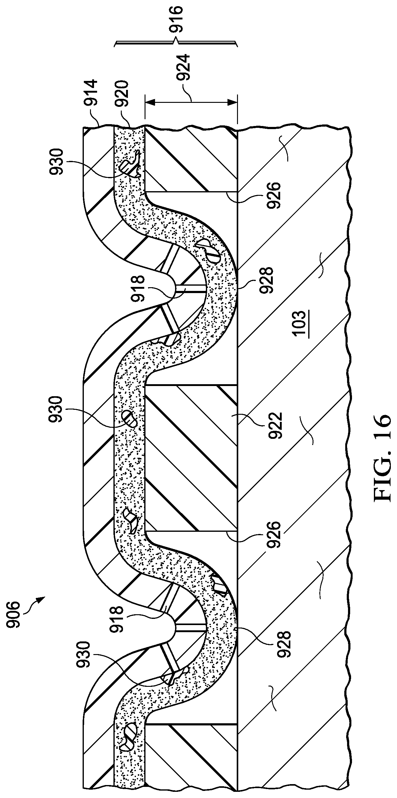
D00013
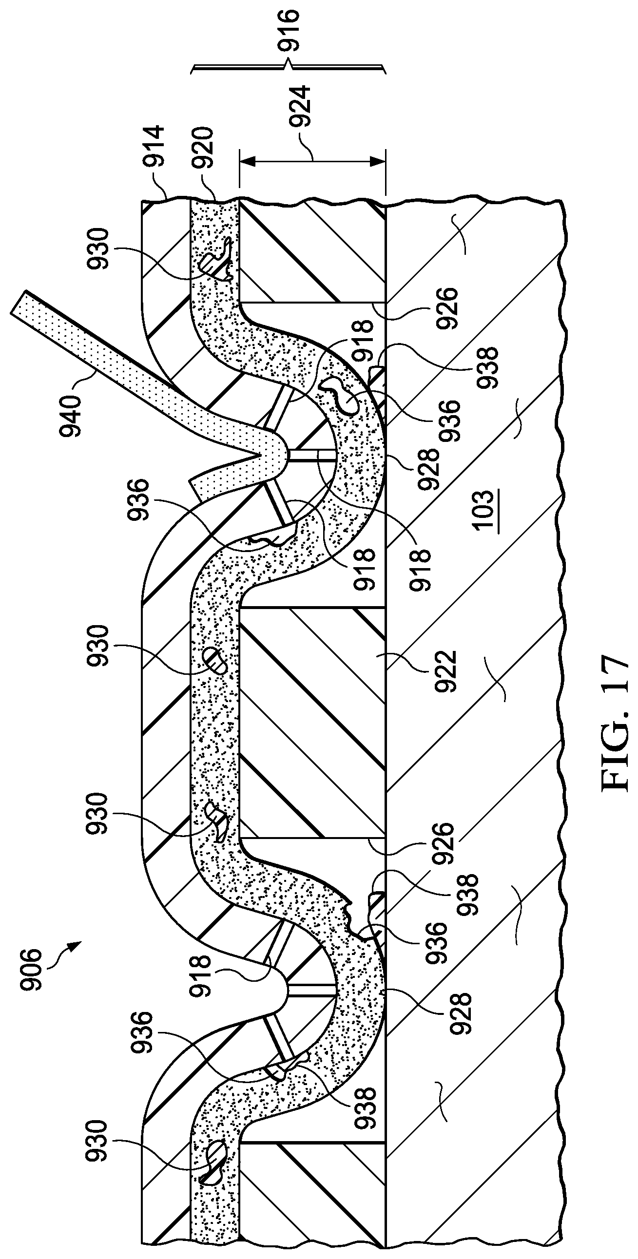
XML
uspto.report is an independent third-party trademark research tool that is not affiliated, endorsed, or sponsored by the United States Patent and Trademark Office (USPTO) or any other governmental organization. The information provided by uspto.report is based on publicly available data at the time of writing and is intended for informational purposes only.
While we strive to provide accurate and up-to-date information, we do not guarantee the accuracy, completeness, reliability, or suitability of the information displayed on this site. The use of this site is at your own risk. Any reliance you place on such information is therefore strictly at your own risk.
All official trademark data, including owner information, should be verified by visiting the official USPTO website at www.uspto.gov. This site is not intended to replace professional legal advice and should not be used as a substitute for consulting with a legal professional who is knowledgeable about trademark law.