Indicating charge status
Liu , et al. January 19, 2
U.S. patent number 10,897,150 [Application Number 15/869,844] was granted by the patent office on 2021-01-19 for indicating charge status. This patent grant is currently assigned to Hand Held Products, Inc.. The grantee listed for this patent is Hand Held Products, Inc.. Invention is credited to Ka Man Au, Derrik Cheng, Stephen J. Colavito, Charles Joseph Cunningham, IV, Gavin Di, HongJian Jin, Jiaqi Liu, Joseph Livingston, Larry Ramsey-Macomber, Lei Wang, David Wilz, Sr., Janna Yu.


| United States Patent | 10,897,150 |
| Liu , et al. | January 19, 2021 |
Indicating charge status
Abstract
Charging/recharging systems and charge status indicators are provided. In one implementation, a charge status indicator includes a charge sensing device configured to sense the charge of a rechargeable power supply. The charge status indicator further includes a detection device configured to compare the sensed charge with a plurality of predetermined levels in order to determine one of a plurality of capacity ranges of the rechargeable power supply. The charge status indicator also includes a first light emitting diode (LED), a second LED, and a switching circuit configured to switch the first and second LEDs on and off using a plurality of predefined illumination patterns to indicate the capacity range of the rechargeable power supply.
| Inventors: | Liu; Jiaqi (Jiangsu, CN), Yu; Janna (Jiangsu, CN), Wang; Lei (Jiangsu, CN), Ramsey-Macomber; Larry (Fairport, NY), Colavito; Stephen J. (Garnet Valley, PA), Cheng; Derrik (Jiangsu, CN), Cunningham, IV; Charles Joseph (Broomall, PA), Au; Ka Man (Philadelphia, PA), Livingston; Joseph (Camillus, NY), Jin; HongJian (Jiangsu, CN), Wilz, Sr.; David (Sewell, NJ), Di; Gavin (Jiangsu, CN) | ||||||||||
|---|---|---|---|---|---|---|---|---|---|---|---|
| Applicant: |
|
||||||||||
| Assignee: | Hand Held Products, Inc. (Fort
Mill, SC) |
||||||||||
| Appl. No.: | 15/869,844 | ||||||||||
| Filed: | January 12, 2018 |
Prior Publication Data
| Document Identifier | Publication Date | |
|---|---|---|
| US 20190222044 A1 | Jul 18, 2019 | |
| Current U.S. Class: | 1/1 |
| Current CPC Class: | H02J 7/0044 (20130101); G06K 7/1413 (20130101); H02J 7/0047 (20130101); H02J 7/0049 (20200101); H02J 7/0048 (20200101); H02J 7/345 (20130101) |
| Current International Class: | H02J 7/00 (20060101); G06K 7/14 (20060101); H02J 7/34 (20060101) |
| Field of Search: | ;320/107 |
References Cited [Referenced By]
U.S. Patent Documents
| 5164652 | November 1992 | Johnson et al. |
| 5939856 | August 1999 | Demuro et al. |
| 6222343 | April 2001 | Crisp et al. |
| 6832725 | December 2004 | Gardiner et al. |
| 7128266 | October 2006 | Zhu et al. |
| 7159783 | January 2007 | Walczyk et al. |
| 7413127 | August 2008 | Ehrhart et al. |
| 7639019 | December 2009 | Bosse et al. |
| 7726575 | June 2010 | Wang et al. |
| 8044815 | October 2011 | Du et al. |
| 8294969 | October 2012 | Plesko |
| 8317105 | November 2012 | Kotlarsky et al. |
| 8322622 | December 2012 | Liu |
| 8366005 | February 2013 | Kotlarsky et al. |
| 8371507 | February 2013 | Haggerty et al. |
| 8376233 | February 2013 | Van Horn et al. |
| 8381979 | February 2013 | Franz |
| 8390909 | March 2013 | Plesko |
| 8408464 | April 2013 | Zhu et al. |
| 8408468 | April 2013 | Horn et al. |
| 8408469 | April 2013 | Good |
| 8424768 | April 2013 | Rueblinger et al. |
| 8448863 | May 2013 | Xian et al. |
| 8457013 | June 2013 | Essinger et al. |
| 8459557 | June 2013 | Havens et al. |
| 8469272 | June 2013 | Kearney |
| 8474712 | July 2013 | Kearney et al. |
| 8479992 | July 2013 | Kotlarsky et al. |
| 8490877 | July 2013 | Kearney |
| 8517271 | August 2013 | Kotlarsky et al. |
| 8523076 | September 2013 | Good |
| 8528818 | September 2013 | Ehrhart et al. |
| 8544737 | October 2013 | Gomez et al. |
| 8548420 | October 2013 | Grunow et al. |
| 8550335 | October 2013 | Samek et al. |
| 8550354 | October 2013 | Gannon et al. |
| 8550357 | October 2013 | Kearney |
| 8556174 | October 2013 | Kosecki et al. |
| 8556176 | October 2013 | Van Horn et al. |
| 8556177 | October 2013 | Hussey et al. |
| 8559767 | October 2013 | Barber et al. |
| 8561895 | October 2013 | Gomez et al. |
| 8561903 | October 2013 | Sauerwein |
| 8561905 | October 2013 | Edmonds et al. |
| 8565107 | October 2013 | Pease et al. |
| 8571307 | October 2013 | Li et al. |
| 8579200 | November 2013 | Samek et al. |
| 8583924 | November 2013 | Caballero et al. |
| 8584945 | November 2013 | Wang et al. |
| 8587595 | November 2013 | Wang |
| 8587697 | November 2013 | Hussey et al. |
| 8588869 | November 2013 | Sauerwein et al. |
| 8590789 | November 2013 | Nahill et al. |
| 8596539 | December 2013 | Havens et al. |
| 8596542 | December 2013 | Havens et al. |
| 8596543 | December 2013 | Havens et al. |
| 8599271 | December 2013 | Havens et al. |
| 8599957 | December 2013 | Peake et al. |
| 8600158 | December 2013 | Li et al. |
| 8600167 | December 2013 | Showering |
| 8602309 | December 2013 | Longacre et al. |
| 8608053 | December 2013 | Meier et al. |
| 8608071 | December 2013 | Liu et al. |
| 8611309 | December 2013 | Wang et al. |
| 8615487 | December 2013 | Gomez et al. |
| 8621123 | December 2013 | Caballero |
| 8622303 | January 2014 | Meier et al. |
| 8628013 | January 2014 | Ding |
| 8628015 | January 2014 | Wang et al. |
| 8628016 | January 2014 | Winegar |
| 8629926 | January 2014 | Wang |
| 8630491 | January 2014 | Longacre et al. |
| 8635309 | January 2014 | Berthiaume et al. |
| 8636200 | January 2014 | Kearney |
| 8636212 | January 2014 | Nahill et al. |
| 8636215 | January 2014 | Ding et al. |
| 8636224 | January 2014 | Wang |
| 8638806 | January 2014 | Wang et al. |
| 8640958 | February 2014 | Lu et al. |
| 8640960 | February 2014 | Wang et al. |
| 8643717 | February 2014 | Li et al. |
| 8646692 | February 2014 | Meier et al. |
| 8646694 | February 2014 | Wang et al. |
| 8657200 | February 2014 | Ren et al. |
| 8659397 | February 2014 | Vargo et al. |
| 8668149 | March 2014 | Good |
| 8678285 | March 2014 | Kearney |
| 8678286 | March 2014 | Smith et al. |
| 8682077 | March 2014 | Longacre |
| D702237 | April 2014 | Oberpriller et al. |
| 8687282 | April 2014 | Feng et al. |
| 8692927 | April 2014 | Pease et al. |
| 8695880 | April 2014 | Bremer et al. |
| 8698949 | April 2014 | Grunow et al. |
| 8702000 | April 2014 | Barber et al. |
| 8717494 | May 2014 | Gannon |
| 8720783 | May 2014 | Biss et al. |
| 8723804 | May 2014 | Fletcher et al. |
| 8723904 | May 2014 | Marty et al. |
| 8727223 | May 2014 | Wang |
| 8740082 | June 2014 | Wilz |
| 8740085 | June 2014 | Furlong et al. |
| 8746563 | June 2014 | Hennick et al. |
| 8750445 | June 2014 | Peake et al. |
| 8752766 | June 2014 | Xian et al. |
| 8756059 | June 2014 | Braho et al. |
| 8757495 | June 2014 | Qu et al. |
| 8760563 | June 2014 | Koziol et al. |
| 8763909 | July 2014 | Reed et al. |
| 8777108 | July 2014 | Coyle |
| 8777109 | July 2014 | Oberpriller et al. |
| 8779898 | July 2014 | Havens et al. |
| 8781520 | July 2014 | Payne et al. |
| 8783573 | July 2014 | Havens et al. |
| 8789757 | July 2014 | Barten |
| 8789758 | July 2014 | Hawley et al. |
| 8789759 | July 2014 | Xian et al. |
| 8794520 | August 2014 | Wang et al. |
| 8794522 | August 2014 | Ehrhart |
| 8794525 | August 2014 | Amundsen et al. |
| 8794526 | August 2014 | Wang et al. |
| 8798367 | August 2014 | Ellis |
| 8807431 | August 2014 | Wang et al. |
| 8807432 | August 2014 | Van Horn et al. |
| 8820630 | September 2014 | Qu et al. |
| 8822848 | September 2014 | Meagher |
| 8824692 | September 2014 | Sheerin et al. |
| 8824696 | September 2014 | Braho |
| 8842849 | September 2014 | Wahl et al. |
| 8844822 | September 2014 | Kotlarsky et al. |
| 8844823 | September 2014 | Fritz et al. |
| 8849019 | September 2014 | Li et al. |
| D716285 | October 2014 | Chaney et al. |
| 8851383 | October 2014 | Yeakley et al. |
| 8854633 | October 2014 | Laffargue |
| 8866963 | October 2014 | Grunow et al. |
| 8868421 | October 2014 | Braho et al. |
| 8868519 | October 2014 | Maloy et al. |
| 8868802 | October 2014 | Barten |
| 8868803 | October 2014 | Caballero |
| 8870074 | October 2014 | Gannon |
| 8879639 | November 2014 | Sauerwein |
| 8880426 | November 2014 | Smith |
| 8881983 | November 2014 | Havens et al. |
| 8881987 | November 2014 | Wang |
| 8903172 | December 2014 | Smith |
| 8908995 | December 2014 | Benos et al. |
| 8910870 | December 2014 | Li et al. |
| 8910875 | December 2014 | Ren et al. |
| 8914290 | December 2014 | Hendrickson et al. |
| 8914788 | December 2014 | Pettinelli et al. |
| 8915439 | December 2014 | Feng et al. |
| 8915444 | December 2014 | Havens et al. |
| 8916789 | December 2014 | Woodburn |
| 8918250 | December 2014 | Hollifield |
| 8918564 | December 2014 | Caballero |
| 8925818 | January 2015 | Kosecki et al. |
| 8939374 | January 2015 | Jovanovski et al. |
| 8942480 | January 2015 | Ellis |
| 8944313 | February 2015 | Williams et al. |
| 8944327 | February 2015 | Meier et al. |
| 8944332 | February 2015 | Harding et al. |
| 8950678 | February 2015 | Germaine et al. |
| D723560 | March 2015 | Zhou et al. |
| 8967468 | March 2015 | Gomez et al. |
| 8971346 | March 2015 | Sevier |
| 8976030 | March 2015 | Cunningham et al. |
| 8976368 | March 2015 | Akel et al. |
| 8978981 | March 2015 | Guan |
| 8978983 | March 2015 | Bremer et al. |
| 8978984 | March 2015 | Hennick et al. |
| 8985456 | March 2015 | Zhu et al. |
| 8985457 | March 2015 | Soule et al. |
| 8985459 | March 2015 | Kearney et al. |
| 8985461 | March 2015 | Gelay et al. |
| 8988578 | March 2015 | Showering |
| 8988590 | March 2015 | Gillet et al. |
| 8991704 | March 2015 | Hopper et al. |
| 8996194 | March 2015 | Davis et al. |
| 8996384 | March 2015 | Funyak et al. |
| 8998091 | April 2015 | Edmonds et al. |
| 9002641 | April 2015 | Showering |
| 9007368 | April 2015 | Laffargue et al. |
| 9010641 | April 2015 | Qu et al. |
| 9015513 | April 2015 | Murawski et al. |
| 9016576 | April 2015 | Brady et al. |
| D730357 | May 2015 | Fitch et al. |
| 9022288 | May 2015 | Nahill et al. |
| 9030964 | May 2015 | Essinger et al. |
| 9033240 | May 2015 | Smith et al. |
| 9033242 | May 2015 | Gillet et al. |
| 9036054 | May 2015 | Koziol et al. |
| 9037344 | May 2015 | Chamberlin |
| 9038911 | May 2015 | Xian et al. |
| 9038915 | May 2015 | Smith |
| D730901 | June 2015 | Oberpriller et al. |
| D730902 | June 2015 | Fitch et al. |
| 9047098 | June 2015 | Barten |
| 9047359 | June 2015 | Caballero et al. |
| 9047420 | June 2015 | Caballero |
| 9047525 | June 2015 | Barber |
| 9047531 | June 2015 | Showering et al. |
| 9049640 | June 2015 | Wang et al. |
| 9053055 | June 2015 | Caballero |
| 9053378 | June 2015 | Hou et al. |
| 9053380 | June 2015 | Xian et al. |
| 9057641 | June 2015 | Amundsen et al. |
| 9058526 | June 2015 | Powilleit |
| 9061527 | June 2015 | Tobin et al. |
| 9064165 | June 2015 | Havens et al. |
| 9064167 | June 2015 | Xian et al. |
| 9064168 | June 2015 | Todeschini et al. |
| 9064254 | June 2015 | Todeschini et al. |
| 9066032 | June 2015 | Wang |
| 9070032 | June 2015 | Corcoran |
| D734339 | July 2015 | Zhou et al. |
| D734751 | July 2015 | Oberpriller et al. |
| 9076459 | July 2015 | Braho et al. |
| 9079423 | July 2015 | Bouverie et al. |
| 9080856 | July 2015 | Laffargue |
| 9082023 | July 2015 | Feng et al. |
| 9084032 | July 2015 | Rautiola et al. |
| 9087250 | July 2015 | Coyle |
| 9092681 | July 2015 | Havens et al. |
| 9092682 | July 2015 | Wilz et al. |
| 9092683 | July 2015 | Koziol et al. |
| 9093141 | July 2015 | Liu |
| D737321 | August 2015 | Lee |
| 9098763 | August 2015 | Lu et al. |
| 9104929 | August 2015 | Todeschini |
| 9104934 | August 2015 | Li et al. |
| 9107484 | August 2015 | Chaney |
| 9111159 | August 2015 | Liu et al. |
| 9111166 | August 2015 | Cunningham |
| 9135483 | September 2015 | Liu et al. |
| 9137009 | September 2015 | Gardiner |
| 9141839 | September 2015 | Xian et al. |
| 9147096 | September 2015 | Wang |
| 9148474 | September 2015 | Skvoretz |
| 9158000 | October 2015 | Sauerwein |
| 9158340 | October 2015 | Reed et al. |
| 9158953 | October 2015 | Gillet et al. |
| 9159059 | October 2015 | Daddabbo et al. |
| 9165174 | October 2015 | Pluck |
| 9171543 | October 2015 | Emerick et al. |
| 9183425 | November 2015 | Wang |
| 9189669 | November 2015 | Zhu et al. |
| 9195844 | November 2015 | Todeschini et al. |
| 9202458 | December 2015 | Braho et al. |
| 9203992 | December 2015 | Ohhashi |
| 9208366 | December 2015 | Liu |
| 9208367 | December 2015 | Wang |
| 9219836 | December 2015 | Bouverie et al. |
| 9224022 | December 2015 | Ackley et al. |
| 9224024 | December 2015 | Bremer et al. |
| 9224027 | December 2015 | Van Horn et al. |
| D747321 | January 2016 | London et al. |
| 9230140 | January 2016 | Ackley |
| 9235553 | January 2016 | Fitch et al. |
| 9239950 | January 2016 | Fletcher |
| 9245492 | January 2016 | Ackley et al. |
| 9443123 | January 2016 | Hejl |
| 9248640 | February 2016 | Heng |
| 9250652 | February 2016 | London et al. |
| 9250712 | February 2016 | Todeschini |
| 9251411 | February 2016 | Todeschini |
| 9258033 | February 2016 | Showering |
| 9262633 | February 2016 | Todeschini et al. |
| 9262660 | February 2016 | Lu et al. |
| 9262662 | February 2016 | Chen |
| 9269036 | February 2016 | Bremer |
| 9270782 | February 2016 | Hala et al. |
| 9274812 | March 2016 | Doren et al. |
| 9275388 | March 2016 | Havens et al. |
| 9277668 | March 2016 | Feng et al. |
| 9280693 | March 2016 | Feng et al. |
| 9286496 | March 2016 | Smith |
| 9297900 | March 2016 | Jiang |
| 9298964 | March 2016 | Li et al. |
| 9301427 | March 2016 | Feng et al. |
| D754205 | April 2016 | Nguyen et al. |
| D754206 | April 2016 | Nguyen et al. |
| 9304376 | April 2016 | Anderson |
| 9310609 | April 2016 | Rueblinger et al. |
| 9313377 | April 2016 | Todeschini et al. |
| 9317037 | April 2016 | Byford et al. |
| 9319548 | April 2016 | Showering et al. |
| D757009 | May 2016 | Oberpriller et al. |
| 9342723 | May 2016 | Liu et al. |
| 9342724 | May 2016 | McCloskey |
| 9361882 | June 2016 | Ressler et al. |
| 9365381 | June 2016 | Colonel et al. |
| 9373018 | June 2016 | Colavito et al. |
| 9375945 | June 2016 | Bowles |
| 9378403 | June 2016 | Wang et al. |
| D760719 | July 2016 | Zhou et al. |
| 9360304 | July 2016 | Chang et al. |
| 9383848 | July 2016 | Daghigh |
| 9384374 | July 2016 | Bianconi |
| 9390304 | July 2016 | Chang et al. |
| 9390596 | July 2016 | Todeschini |
| D762604 | August 2016 | Fitch et al. |
| 9411386 | August 2016 | Sauerwein |
| 9412242 | August 2016 | Van Horn et al. |
| 9418269 | August 2016 | Havens et al. |
| 9418270 | August 2016 | Van Volkinburg et al. |
| 9423318 | August 2016 | Lui et al. |
| D766244 | September 2016 | Zhou et al. |
| 9443222 | September 2016 | Singel et al. |
| 9454689 | September 2016 | McCloskey et al. |
| 9464885 | October 2016 | Lloyd et al. |
| 9465967 | October 2016 | Xian et al. |
| 9478113 | October 2016 | Xie et al. |
| 9478983 | October 2016 | Kather et al. |
| D771631 | November 2016 | Fitch et al. |
| 9481186 | November 2016 | Bouverie et al. |
| 9487113 | November 2016 | Schukalski |
| 9488986 | November 2016 | Solanki |
| 9489782 | November 2016 | Payne et al. |
| 9490540 | November 2016 | Davies et al. |
| 9491729 | November 2016 | Rautiola et al. |
| 9497092 | November 2016 | Gomez et al. |
| 9507974 | November 2016 | Todeschini |
| 9519814 | December 2016 | Cudzilo |
| 9521331 | December 2016 | Bessettes et al. |
| 9530038 | December 2016 | Xian et al. |
| D777166 | January 2017 | Bidwell et al. |
| 9558386 | January 2017 | Yeakley |
| 9572901 | February 2017 | Todeschini |
| 9606581 | March 2017 | Howe et al. |
| D783601 | April 2017 | Schulte et al. |
| D785617 | May 2017 | Bidwell et al. |
| D785636 | May 2017 | Oberpriller et al. |
| 9646189 | May 2017 | Lu et al. |
| 9646191 | May 2017 | Unemyr et al. |
| 9652648 | May 2017 | Ackley et al. |
| 9652653 | May 2017 | Todeschini et al. |
| 9656487 | May 2017 | Ho et al. |
| 9659198 | May 2017 | Giordano et al. |
| D790505 | June 2017 | Vargo et al. |
| D790546 | June 2017 | Zhou et al. |
| 9680282 | June 2017 | Hanenburg |
| 9697401 | July 2017 | Feng et al. |
| 9701140 | July 2017 | Alaganchetty et al. |
| 2006/0061332 | March 2006 | Neu et al. |
| 2006/0192015 | August 2006 | DiGiovanna |
| 2007/0063048 | March 2007 | Havens et al. |
| 2009/0134221 | May 2009 | Zhu et al. |
| 2010/0134072 | June 2010 | Neu et al. |
| 2010/0177076 | July 2010 | Essinger et al. |
| 2010/0177080 | July 2010 | Essinger et al. |
| 2010/0177707 | July 2010 | Essinger et al. |
| 2010/0177749 | July 2010 | Essinger et al. |
| 2011/0169999 | July 2011 | Grunow et al. |
| 2011/0202554 | August 2011 | Powilleit et al. |
| 2012/0111946 | May 2012 | Golant |
| 2012/0116379 | May 2012 | Yates et al. |
| 2012/0168512 | July 2012 | Kotlarsky et al. |
| 2012/0193423 | August 2012 | Samek |
| 2012/0194692 | August 2012 | Mers et al. |
| 2012/0203647 | August 2012 | Smith |
| 2012/0223141 | September 2012 | Good et al. |
| 2013/0043312 | February 2013 | Van Horn |
| 2013/0075168 | March 2013 | Amundsen et al. |
| 2013/0175341 | July 2013 | Kearney et al. |
| 2013/0175343 | July 2013 | Good |
| 2013/0257744 | October 2013 | Daghigh et al. |
| 2013/0257759 | October 2013 | Daghigh |
| 2013/0270346 | October 2013 | Xian et al. |
| 2013/0277431 | October 2013 | DiGiovanna |
| 2013/0292475 | November 2013 | Kotlarsky et al. |
| 2013/0292477 | November 2013 | Hennick et al. |
| 2013/0293539 | November 2013 | Hunt et al. |
| 2013/0293540 | November 2013 | Laffargue et al. |
| 2013/0306728 | November 2013 | Thuries et al. |
| 2013/0306731 | November 2013 | Pedraro |
| 2013/0307964 | November 2013 | Bremer et al. |
| 2013/0308625 | November 2013 | Park et al. |
| 2013/0313324 | November 2013 | Koziol et al. |
| 2013/0332524 | December 2013 | Fiala et al. |
| 2013/0332996 | December 2013 | Fiala et al. |
| 2014/0001267 | January 2014 | Giordano et al. |
| 2014/0002828 | January 2014 | Laffargue et al. |
| 2014/0025584 | January 2014 | Liu et al. |
| 2014/0100813 | January 2014 | Showering |
| 2014/0034734 | February 2014 | Sauerwein |
| 2014/0036848 | February 2014 | Pease et al. |
| 2014/0038124 | February 2014 | Gill |
| 2014/0039693 | February 2014 | Havens et al. |
| 2014/0049120 | February 2014 | Kohtz et al. |
| 2014/0049635 | February 2014 | Laffargue et al. |
| 2014/0061306 | March 2014 | Wu et al. |
| 2014/0063289 | March 2014 | Hussey et al. |
| 2014/0066136 | March 2014 | Sauerwein et al. |
| 2014/0067692 | March 2014 | Ye et al. |
| 2014/0070005 | March 2014 | Nahill et al. |
| 2014/0071840 | March 2014 | Venancio |
| 2014/0074746 | March 2014 | Wang |
| 2014/0076974 | March 2014 | Havens et al. |
| 2014/0078342 | March 2014 | Li et al. |
| 2014/0098792 | April 2014 | Wang et al. |
| 2014/0100774 | April 2014 | Showering |
| 2014/0103115 | April 2014 | Meier et al. |
| 2014/0104413 | April 2014 | McCloskey et al. |
| 2014/0104414 | April 2014 | McCloskey et al. |
| 2014/0104416 | April 2014 | Giordano et al. |
| 2014/0106725 | April 2014 | Sauerwein |
| 2014/0108010 | April 2014 | Maltseff et al. |
| 2014/0108402 | April 2014 | Gomez et al. |
| 2014/0108682 | April 2014 | Caballero |
| 2014/0110485 | April 2014 | Toa et al. |
| 2014/0114530 | April 2014 | Fitch et al. |
| 2014/0125853 | May 2014 | Wang |
| 2014/0125999 | May 2014 | Longacre et al. |
| 2014/0129378 | May 2014 | Richardson |
| 2014/0131443 | May 2014 | Smith |
| 2014/0131444 | May 2014 | Wang |
| 2014/0133379 | May 2014 | Wang et al. |
| 2014/0136208 | May 2014 | Maltseff et al. |
| 2014/0140585 | May 2014 | Wang |
| 2014/0152882 | June 2014 | Samek et al. |
| 2014/0158770 | June 2014 | Sevier et al. |
| 2014/0159869 | June 2014 | Zumsteg et al. |
| 2014/0166755 | June 2014 | Liu et al. |
| 2014/0166757 | June 2014 | Smith |
| 2014/0166759 | June 2014 | Liu et al. |
| 2014/0168787 | June 2014 | Wang et al. |
| 2014/0175165 | June 2014 | Havens et al. |
| 2014/0191684 | July 2014 | Valois |
| 2014/0191913 | July 2014 | Ge et al. |
| 2014/0197239 | July 2014 | Havens et al. |
| 2014/0197304 | July 2014 | Feng et al. |
| 2014/0204268 | July 2014 | Grunow et al. |
| 2014/0214631 | July 2014 | Hansen |
| 2014/0217166 | August 2014 | Berthiaume et al. |
| 2014/0217180 | August 2014 | Liu |
| 2014/0231500 | August 2014 | Ehrhart et al. |
| 2014/0247315 | September 2014 | Marty et al. |
| 2014/0263493 | September 2014 | Amurgis et al. |
| 2014/0263645 | September 2014 | Smith et al. |
| 2014/0270196 | September 2014 | Braho et al. |
| 2014/0270229 | September 2014 | Braho |
| 2014/0278387 | September 2014 | DiGregorio |
| 2014/0282210 | September 2014 | Bianconi |
| 2014/0288933 | September 2014 | Braho et al. |
| 2014/0297058 | October 2014 | Barker et al. |
| 2014/0299665 | October 2014 | Barber et al. |
| 2014/0332590 | November 2014 | Wang et al. |
| 2014/0351317 | November 2014 | Smith et al. |
| 2014/0362184 | December 2014 | Jovanovski et al. |
| 2014/0363015 | December 2014 | Braho |
| 2014/0369511 | December 2014 | Sheerin et al. |
| 2014/0374483 | December 2014 | Lu |
| 2014/0374485 | December 2014 | Xian et al. |
| 2015/0001301 | January 2015 | Ouyang |
| 2015/0009338 | January 2015 | Laffargue et al. |
| 2015/0014416 | January 2015 | Kotlarsky et al. |
| 2015/0021397 | January 2015 | Rueblinger et al. |
| 2015/0028104 | January 2015 | Ma et al. |
| 2015/0029002 | January 2015 | Yeakley et al. |
| 2015/0032709 | January 2015 | Maloy et al. |
| 2015/0039309 | February 2015 | Braho et al. |
| 2015/0040378 | February 2015 | Saber et al. |
| 2015/0049347 | February 2015 | Laffargue et al. |
| 2015/0051992 | February 2015 | Smith |
| 2015/0053769 | February 2015 | Thuries et al. |
| 2015/0062366 | March 2015 | Liu et al. |
| 2015/0063215 | March 2015 | Wang |
| 2015/0088522 | March 2015 | Hendrickson et al. |
| 2015/0096872 | April 2015 | Woodburn |
| 2015/0100196 | April 2015 | Hollifield |
| 2015/0115035 | April 2015 | Meier et al. |
| 2015/0127791 | May 2015 | Kosecki et al. |
| 2015/0128116 | May 2015 | Chen et al. |
| 2015/0133047 | May 2015 | Smith et al. |
| 2015/0134470 | May 2015 | Hejl et al. |
| 2015/0136851 | May 2015 | Harding et al. |
| 2015/0142492 | May 2015 | Kumar |
| 2015/0144692 | May 2015 | Hejl |
| 2015/0144698 | May 2015 | Teng et al. |
| 2015/0149946 | May 2015 | Benos et al. |
| 2015/0161429 | June 2015 | Xian |
| 2015/0178523 | June 2015 | Gelay et al. |
| 2015/0178537 | June 2015 | El et al. |
| 2015/0178685 | June 2015 | Krumel et al. |
| 2015/0181109 | June 2015 | Gillet et al. |
| 2015/0186703 | July 2015 | Chen et al. |
| 2015/0199957 | July 2015 | Funyak et al. |
| 2015/0210199 | July 2015 | Payne |
| 2015/0212565 | July 2015 | Murawski et al. |
| 2015/0213647 | July 2015 | Laffargue et al. |
| 2015/0220753 | August 2015 | Zhu et al. |
| 2015/0220901 | August 2015 | Gomez et al. |
| 2015/0227189 | August 2015 | Davis et al. |
| 2015/0236984 | August 2015 | Sevier |
| 2015/0239348 | August 2015 | Chamberlin |
| 2015/0242658 | August 2015 | Nahill et al. |
| 2015/0248572 | September 2015 | Soule et al. |
| 2015/0254485 | September 2015 | Feng et al. |
| 2015/0261643 | September 2015 | Caballero et al. |
| 2015/0264624 | September 2015 | Wang et al. |
| 2015/0268971 | September 2015 | Barten |
| 2015/0269402 | September 2015 | Barber et al. |
| 2015/0288689 | October 2015 | Todeschini et al. |
| 2015/0288896 | October 2015 | Wang |
| 2015/0310243 | October 2015 | Ackley |
| 2015/0310244 | October 2015 | Xian et al. |
| 2015/0310389 | October 2015 | Crimm et al. |
| 2015/0312780 | October 2015 | Wang et al. |
| 2015/0327012 | November 2015 | Bian et al. |
| 2016/0014251 | January 2016 | Hejl |
| 2016/0025697 | January 2016 | Alt et al. |
| 2016/0026838 | January 2016 | Gillet et al. |
| 2016/0026839 | January 2016 | Qu et al. |
| 2016/0040982 | February 2016 | Li et al. |
| 2016/0042241 | February 2016 | Todeschini |
| 2016/0057230 | February 2016 | Todeschini et al. |
| 2016/0062473 | March 2016 | Bouchat et al. |
| 2016/0092805 | March 2016 | Geisler et al. |
| 2016/0099581 | April 2016 | Kawamura |
| 2016/0101936 | April 2016 | Chamberlin |
| 2016/0102975 | April 2016 | McCloskey et al. |
| 2016/0104019 | April 2016 | Todeschini et al. |
| 2016/0104274 | April 2016 | Jovanovski et al. |
| 2016/0109219 | April 2016 | Ackley et al. |
| 2016/0109220 | April 2016 | Laffargue |
| 2016/0109224 | April 2016 | Thuries et al. |
| 2016/0112631 | April 2016 | Ackley et al. |
| 2016/0112643 | April 2016 | Laffargue et al. |
| 2016/0117627 | April 2016 | Raj et al. |
| 2016/0124516 | May 2016 | Schoon et al. |
| 2016/0125217 | May 2016 | Todeschini |
| 2016/0125342 | May 2016 | Miller et al. |
| 2016/0133253 | May 2016 | Braho et al. |
| 2016/0171597 | June 2016 | Todeschini |
| 2016/0171666 | June 2016 | McCloskey |
| 2016/0171720 | June 2016 | Todeschini |
| 2016/0171775 | June 2016 | Todeschini et al. |
| 2016/0171777 | June 2016 | Todeschini et al. |
| 2016/0174674 | June 2016 | Oberpriller et al. |
| 2016/0178479 | June 2016 | Goldsmith |
| 2016/0178685 | June 2016 | Young et al. |
| 2016/0178707 | June 2016 | Young et al. |
| 2016/0179132 | June 2016 | Harr et al. |
| 2016/0179143 | June 2016 | Bidwell et al. |
| 2016/0179368 | June 2016 | Roeder |
| 2016/0179378 | June 2016 | Kent et al. |
| 2016/0180130 | June 2016 | Bremer |
| 2016/0180133 | June 2016 | Oberpriller et al. |
| 2016/0180136 | June 2016 | Meier et al. |
| 2016/0180594 | June 2016 | Todeschini |
| 2016/0180663 | June 2016 | McMahan et al. |
| 2016/0180678 | June 2016 | Ackley et al. |
| 2016/0180713 | June 2016 | Bernhardt et al. |
| 2016/0185136 | June 2016 | Ng et al. |
| 2016/0185291 | June 2016 | Chamberlin |
| 2016/0186926 | June 2016 | Oberpriller et al. |
| 2016/0188861 | June 2016 | Todeschini |
| 2016/0188939 | June 2016 | Sailors et al. |
| 2016/0188940 | June 2016 | Lu et al. |
| 2016/0188941 | June 2016 | Todeschini et al. |
| 2016/0188942 | June 2016 | Good et al. |
| 2016/0188943 | June 2016 | Linwood |
| 2016/0188944 | June 2016 | Wilz |
| 2016/0189076 | June 2016 | Mellott et al. |
| 2016/0189087 | June 2016 | Morton et al. |
| 2016/0189088 | June 2016 | Pecorari et al. |
| 2016/0189092 | June 2016 | George et al. |
| 2016/0189284 | June 2016 | Mellott et al. |
| 2016/0189288 | June 2016 | Todeschini |
| 2016/0189366 | June 2016 | Chamberlin et al. |
| 2016/0189443 | June 2016 | Smith |
| 2016/0189447 | June 2016 | Valenzuela |
| 2016/0189489 | June 2016 | Au et al. |
| 2016/0191684 | June 2016 | DiPiazza et al. |
| 2016/0192051 | June 2016 | DiPiazza et al. |
| 2016/0125873 | July 2016 | Braho et al. |
| 2016/0202951 | July 2016 | Pike et al. |
| 2016/0202958 | July 2016 | Zabel et al. |
| 2016/0202959 | July 2016 | Doubleday et al. |
| 2016/0203021 | July 2016 | Pike et al. |
| 2016/0203429 | July 2016 | Mellott et al. |
| 2016/0203797 | July 2016 | Pike et al. |
| 2016/0203820 | July 2016 | Zabel et al. |
| 2016/0204623 | July 2016 | Haggert et al. |
| 2016/0204636 | July 2016 | Allen et al. |
| 2016/0204638 | July 2016 | Miraglia et al. |
| 2016/0316190 | July 2016 | McCloskey et al. |
| 2016/0227912 | August 2016 | Oberpriller et al. |
| 2016/0232891 | August 2016 | Pecorari |
| 2016/0292477 | October 2016 | Bidwell |
| 2016/0294779 | October 2016 | Yeakley et al. |
| 2016/0306769 | October 2016 | Kohtz et al. |
| 2016/0314276 | October 2016 | Sewell et al. |
| 2016/0314294 | October 2016 | Kubler et al. |
| 2016/0323310 | November 2016 | Todeschini et al. |
| 2016/0325677 | November 2016 | Fitch et al. |
| 2016/0327614 | November 2016 | Young et al. |
| 2016/0327930 | November 2016 | Charpentier et al. |
| 2016/0328762 | November 2016 | Pape |
| 2016/0330218 | November 2016 | Hussey et al. |
| 2016/0343163 | November 2016 | Venkatesha et al. |
| 2016/0343176 | November 2016 | Ackley |
| 2016/0364914 | December 2016 | Todeschini |
| 2016/0370220 | December 2016 | Ackley et al. |
| 2016/0372282 | December 2016 | Bandringa |
| 2016/0373847 | December 2016 | Vargo et al. |
| 2016/0377414 | December 2016 | Thuries et al. |
| 2016/0377417 | December 2016 | Jovanovski et al. |
| 2017/0010141 | January 2017 | Ackley |
| 2017/0010328 | January 2017 | Mullen et al. |
| 2017/0010780 | January 2017 | Waldron et al. |
| 2017/0012448 | January 2017 | Miller |
| 2017/0016714 | January 2017 | Laffargue et al. |
| 2017/0018094 | January 2017 | Todeschini |
| 2017/0046603 | February 2017 | Lee et al. |
| 2017/0047864 | February 2017 | Stang et al. |
| 2017/0053146 | February 2017 | Liu et al. |
| 2017/0053147 | February 2017 | Geramine et al. |
| 2017/0053647 | February 2017 | Nichols et al. |
| 2017/0055606 | March 2017 | Xu et al. |
| 2017/0060316 | March 2017 | Larson |
| 2017/0061961 | March 2017 | Nichols et al. |
| 2017/0064634 | March 2017 | Van Horn et al. |
| 2017/0083730 | March 2017 | Feng et al. |
| 2017/0091502 | March 2017 | Furlong et al. |
| 2017/0091706 | March 2017 | Lloyd et al. |
| 2017/0091741 | March 2017 | Todeschini |
| 2017/0091904 | March 2017 | Ventress |
| 2017/0092908 | March 2017 | Chaney |
| 2017/0094238 | March 2017 | Germaine |
| 2017/0098947 | April 2017 | Wolski |
| 2017/0100949 | April 2017 | Celinder et al. |
| 2017/0108838 | April 2017 | Todeschini et al. |
| 2017/0108895 | April 2017 | Chamberlin et al. |
| 2017/0118355 | April 2017 | Wong et al. |
| 2017/0123598 | May 2017 | Phan et al. |
| 2017/0124369 | May 2017 | Rueblinger et al. |
| 2017/0124396 | May 2017 | Todeschini et al. |
| 2017/0124687 | May 2017 | McCloskey et al. |
| 2017/0126873 | May 2017 | McGary et al. |
| 2017/0126904 | May 2017 | D'Armancourt et al. |
| 2017/0139012 | May 2017 | Smith |
| 2017/0140329 | May 2017 | Bernhardt et al. |
| 2017/0140731 | May 2017 | Smith |
| 2017/0147847 | May 2017 | Berggren et al. |
| 2017/0150124 | May 2017 | Thuries |
| 2017/0169198 | June 2017 | Nichols |
| 2017/0171035 | June 2017 | Lu et al. |
| 2017/0171703 | June 2017 | Maheswaranathan |
| 2017/0171803 | June 2017 | Maheswaranathan |
| 2017/0180359 | June 2017 | Wolski et al. |
| 2017/0180577 | June 2017 | Nguon et al. |
| 2017/0181299 | June 2017 | Shi et al. |
| 2017/0190192 | July 2017 | Delario et al. |
| 2017/0193432 | July 2017 | Bernhardt |
| 2017/0193461 | July 2017 | Jonas et al. |
| 2017/0193727 | July 2017 | Van Horn et al. |
| 2017/0199266 | July 2017 | Rice et al. |
| 2017/0200108 | July 2017 | Au et al. |
| 2017/0200275 | July 2017 | McCloskey et al. |
| 2005211521 | Mar 2006 | AU | |||
| 2013163789 | Nov 2013 | WO | |||
Attorney, Agent or Firm: Alston & Bird LLP
Claims
The invention claimed is:
1. A charging system comprising: a handheld electronic device having a rechargeable power supply; a base charger configured to support the handheld electronic device during a charging stage, the base charger being configured to provide electric charge to the handheld electronic device during the charging stage to recharge the rechargeable power supply; a charge sensor configured to sense the charge of the rechargeable power supply; a detection device configured to compare the sensed charge of the rechargeable power supply with a plurality of predetermined charge levels in order to determine one of a plurality of capacity ranges of the rechargeable power supply; and a charge status indicator comprises first and second light emitting diodes (LEDs) and a switching circuit; wherein the switching circuit of the charge status indicator is configured to switch the first and second LEDs according to one of a plurality of predefined illumination patterns to indicate a capacity range of the rechargeable power supply corresponding to the capacity range determined by the detection device and wherein at least one of the predefined illumination patterns indicate a ready to use status corresponding to a capacity range that indicates availability of charge for performing a function by the handheld electronic device before the rechargeable power supply needs to be recharged further.
2. The charging system of claim 1, wherein the charge status indicator is incorporated in the base charger.
3. The charging system of claim 1, wherein the rechargeable power supply includes at least one supercapacitor.
4. The charging system of claim 1, wherein the handheld electronic device is a wireless barcode scanner.
5. The charging system of claim 1, wherein a plurality of capacity ranges includes a first range designating an "at or near empty" status, a second range designating a "ready to use" status, a third range designating a "greater than half capacity" status, and a fourth range designating an "at or near full capacity" status.
6. The charging system of claim 5, wherein the switching circuit is configured to switch the first and second LEDs according to a first predefined illumination pattern when the charge of the rechargeable power supply falls within the first range, a second predefined illumination pattern when the charge of the rechargeable power supply falls within the second range, a third predefined illumination pattern when the charge of the rechargeable power supply falls within the third range, and a fourth predefined illumination pattern when the charge of the rechargeable power supply falls within the fourth range.
7. The charging system of claim 6, wherein: the first predefined illumination pattern includes repeating a cycle of switching the first LED on for about 500 ms and off for about 500 ms; the second predefined illumination pattern includes repeating a cycle of switching the second LED on for about 500 ms and off for about 500 ms; the third predefined illumination pattern includes repeating a cycle of switching the second LED on for about 1000 ms and off for about 500 ms; and the fourth predefined illumination pattern includes switching the second LED on.
8. The charging system of claim 1, wherein the first and second LEDs have different colors.
9. The charging system of claim 1, wherein the switching circuit is configured to switch the first and second LEDs off when the base charger is not charging the rechargeable power supply or when the handheld electronic device is not properly supported by the base charger.
10. The charging system of claim 1, wherein the switching circuit is configured to switch at least one of the first and second LEDs in a rapid on/off pattern when at least one of the charge sensor and detection device detects at least one of a charging error and a condition in which the charging has been suspended.
11. The charging system of claim 1, wherein the charge status indicator is incorporated in the handheld electronic device.
12. A recharging device comprising: a charging cradle configured to support a handheld electronic device during a charging stage, the charging cradle being configured to supply electric power to the handheld electronic device during the charging stage to recharge a supercapacitor of the handheld electronic device; a charge status indicator comprises first and second light emitting diodes (LEDs) and a control circuit; and a sensor configured to continuously sense a charge of the supercapacitor to determine one of a plurality of capacity ranges of the supercapacitor; wherein the control circuit of the charge status indicator is configured to switch the first and second LEDs on and off using a plurality of predefined illumination patterns to indicate a capacity range of the supercapacitor determined by the sensor, and wherein at least one of the predefined illumination patterns indicate a ready to use status corresponding to a capacity range that indicates availability of charge for performing a function by the handheld electronic device before the supercapacitor needs to be recharged further.
13. The recharging device of claim 12, wherein the charge status indicator is incorporated in the charging cradle.
14. The recharging device of claim 12, wherein the handheld electronic device is a wireless barcode scanner.
15. The recharging device of claim 12, wherein the plurality of capacity ranges includes a first range designating an "at or near empty" status, a second range designating a "ready to use" status, a third range designating a "greater than half capacity" status, and a fourth range designating an "at or near full capacity" status.
16. The recharging device of claim 15, wherein the control circuit is configured to switch the first and second LEDs in a first predefined illumination pattern when the charge of the supercapacitor falls within the first range, a second predefined illumination pattern when the charge of the supercapacitor falls within the second range, a third predefined illumination pattern when the charge of the supercapacitor falls within the third range, and a fourth predefined illumination pattern when the charge of the supercapacitor falls within the fourth range.
17. The recharging device of claim 16, wherein the first predefined illumination pattern includes repeating a cycle of switching the first LED on for about 500 ms and off for about 500 ms, the second predefined illumination pattern includes repeating a cycle of switching the second LED on for about 500 ms and off for about 500 ms, the third predefined illumination pattern includes repeating a cycle of switching the second LED on for about 1000 ms and off for about 500 ms, and the fourth predefined illumination pattern includes switching the second LED on.
18. The recharging device of claim 12, wherein the control circuit is configured to switch both of the first and second LEDs off when the charging cradle is not charging the supercapacitor or when the handheld electronic device is not properly supported by the charging cradle, and wherein the control circuit is further configured to switch at least one of the first and second LEDs in a rapid on/off pattern when the sensor detects a charging error.
19. A charge status indicator comprising: a charge sensing device configured to sense a charge of a rechargeable power supply; a detection device configured to compare the sensed charge with a plurality of predetermined levels in order to determine one of a plurality of capacity ranges of the rechargeable power supply; a first light emitting diode (LED); a second LED; and a switching circuit configured to switch the first and second LEDs on and off using a plurality of predefined illumination patterns to indicate a capacity range of the rechargeable power supply, wherein at least one of the predefined illumination patterns indicate a ready to use status corresponding to a capacity range that indicates availability of charge for performing a function by a handheld electronic device before the rechargeable power supply needs to be recharged further.
20. The charge status indicator of claim 19, wherein the rechargeable power supply includes at least one supercapacitor and is incorporated in a wireless barcode scanner.
21. The charge status indicator of claim 20, wherein the charge status indicator is incorporated in a cradle that is configured to support the wireless barcode scanner during a charging process, and wherein the cradle is further configured to provide electric charge to the wireless barcode scanner during a charging process to recharge the supercapacitor of the wireless barcode scanner.
22. The charge status indicator of claim 19, wherein the plurality of capacity ranges includes a first range designating a "near empty" status, a second range designating a "ready to use" status, a third range designating a "greater than half capacity" status, and a fourth range designating an "at or near full capacity" status.
23. The charge status indicator of claim 22, wherein the switching circuit is configured to switch the first and second LEDs in a first predefined illumination pattern when the charge of the rechargeable power supply falls within the first range, a second predefined illumination pattern when the charge of the rechargeable power supply falls within the second range, a third predefined illumination pattern when the charge of the rechargeable power supply falls within the third range, and a fourth predefined illumination pattern when the charge of the rechargeable power supply falls within the fourth range.
24. The charge status indicator of claim 23, wherein the first predefined illumination pattern includes repeating a cycle of switching the first LED on for about 500 ms and off for about 500 ms, the second predefined illumination pattern includes repeating a cycle of switching the second LED on for about 500 ms and off for about 500 ms, the third predefined illumination pattern includes repeating a cycle of switching the second LED on for about 1000 ms and off for about 500 ms, and the fourth predefined illumination pattern includes switching the second LED on.
25. The charge status indicator of claim 19, wherein the rechargeable power supply is incorporated in a handheld electronic device and is recharged when the handheld electronic device is placed on a charging cradle, and wherein the switching circuit is configured to switch the first and second LEDs off when the charging cradle is not charging the rechargeable power supply or when the handheld electronic device is not properly supported by the charging cradle.
26. The charge status indicator of claim 19, wherein the switching circuit is configured to switch at least one of the first and second LEDs in a rapid on/off pattern when at least one of the charge sensing device and detection device detects at least one of a charging error and a condition in which the charging process has been suspended.
Description
FIELD OF THE INVENTION
The present invention relates to portable electronic devices and more particularly relates to devices for indicating the charge status of rechargeable power supplies used for powering the portable electronic devices.
BACKGROUND
Generally speaking, portable electronic devices are included in many aspects of everyday life. Examples of some portable electronic devices may include cell phones, wireless landline telephones, electric razors, calculators, wireless computer peripherals, radios, flashlights, wireless barcode scanners, just to name a few. Typically, these portable devices are powered by primary cell (non-rechargeable) batteries or secondary cell (rechargeable) batteries.
Although rechargeable batteries are normally a better economic choice than primary cell batteries and add less toxic waste to landfills, other power sources are available for powering portable electronic devices. For example, supercapacitors are a battery-free alternative that provides many advantages over conventional batteries.
Although supercapacitors do not hold a charge for as long as batteries, supercapacitors are able to be charged or recharged much faster than rechargeable batteries. Also, supercapacitors can be discharged and recharged hundreds of thousands of times without losing their charging capacity. On the other hand, rechargeable batteries may only be able to be discharged and recharged a few hundred times before their charging capacity declines to a point of no longer being usable.
Another advantage is that supercapacitors do not degrade like rechargeable batteries and therefore may never need to be replaced. Also, since there are no chemical reactions involved in the charging and discharging of supercapacitors, there is therefore no decay of chemical materials. Thus, supercapacitors can eliminate the environmental issues associated with the use and disposal of primary cell batteries and rechargeable batteries.
Because of the familiarity with rechargeable batteries, many users may have become accustomed to the practice of charging, discharging, and recharging of rechargeable batteries. Particularly, users may be aware that charging batteries before a first use may take hours and that recharging the batteries may take 10-30 minutes, depending on the type of batteries being used. Therefore, a user might repeatedly check the status of the battery charging process until the batteries are eventually ready to be used. Typically, there may be a single indicator for indicating that the rechargeable batteries are ready to be used.
However, since supercapacitors are charged, discharged, and recharged much faster than batteries, a new type of charge status indication process would be beneficial for users. Therefore, a need exists for a charge status indicator for indicating more information regarding the charge of a rechargeable power supply, particularly a rechargeable supercapacitor. In this way, a user can be informed of the various stages of charge status levels of the supercapacitors.
SUMMARY
Accordingly, in one aspect, the present invention embraces systems, devices, and methods for indicating the charge status of power supplies used for providing power to portable electronic devices. In particular, with the advent of new power supply technologies, such as supercapacitors, that are now being used in common electronic devices, charge status can be indicated to the user in a faster way and in a way that expresses more information than what is typically provided.
In an exemplary embodiment, a charging system is provided. The charging system includes a handheld electronic device having a rechargeable power supply and a base charger configured to support the handheld electronic device during a charging stage. The base charger is configured to provide electric charge to the handheld electronic device during the charging stage to recharge the rechargeable power supply. The charging system further includes a charge sensor configured to sense the charge of the rechargeable power supply and a detection device configured to compare the sensed charge of the rechargeable power supply with a plurality of predetermined charge levels in order to determine one of a plurality of capacity ranges of the rechargeable power supply. The charging system also includes a charge status indicator comprises first and second light emitting diodes (LEDs) and a switching circuit. The switching circuit of the charge status indicator is configured to switch the first and second LEDs according to one of a plurality of predefined illumination patterns to indicate a capacity range of the rechargeable power supply corresponding to the capacity range determined by the detection device.
In another exemplary embodiment, a recharging device is provided. In this embodiment, the recharging device comprises a charging cradle configured to support a handheld electronic device during a charging stage. The charging cradle is configured to supply electric power to the handheld electronic device during the charging stage to recharge a supercapacitor of the handheld electronic device. The recharging device also includes a charge status indicator comprising first and second light emitting diodes (LEDs) and a control circuit. Also, the recharging device includes a sensor configured to continuously sense the charge of the supercapacitor to determine one of a plurality of capacity ranges of the supercapacitor. The control circuit of the charge status indicator is configured to switch the first and second LEDs on and off using a plurality of predefined illumination patterns to indicate the capacity range of the supercapacitor determined by the sensor.
In yet another exemplary embodiment, a charge status indicator includes a charge sensing device configured to sense the charge of a rechargeable power supply and a detection device configured to compare the sensed charge with a plurality of predetermined levels in order to determine one of a plurality of capacity ranges of the rechargeable power supply. The charge status indicator further includes a first light emitting diode (LED), a second LED, and a switching circuit configured to switch the first and second LEDs on and off using a plurality of predefined illumination patterns to indicate the capacity range of the rechargeable power supply.
The foregoing illustrative summary, as well as other exemplary objectives and/or advantages of the invention, and the manner in which the same are accomplished, are further explained within the following detailed description and its accompanying drawings.
BRIEF DESCRIPTION OF THE DRAWINGS
FIG. 1 schematically depicts a perspective view of a charging system according to an embodiment of the present invention.
FIG. 2 schematically depicts a top view of the recharging device shown in FIG. 1 according to an embodiment of the present invention.
FIG. 3 schematically depicts a perspective view of the portable electronic device shown in FIG. 1 according to an embodiment of the present invention.
FIG. 4 schematically depicts a perspective view of a charging system according to a second embodiment of the present invention.
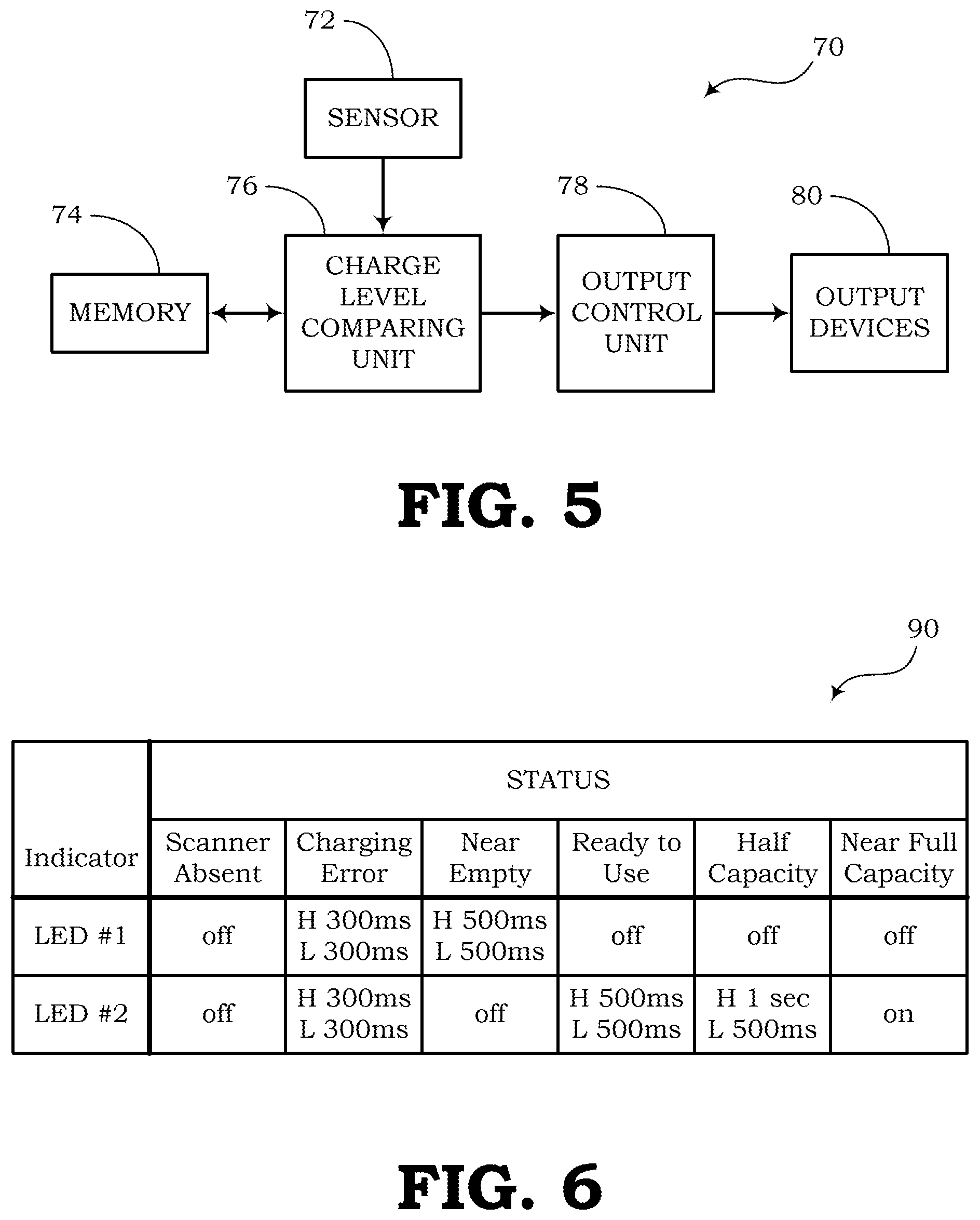
FIG. 5 schematically depicts a block diagram of a charge status indicator according to an embodiment of the present invention.
FIG. 6 schematically depicts a chart showing various illumination patterns of LEDs for indicating the status of a rechargeable power supply according to an embodiment of the present invention.
DETAILED DESCRIPTION
The present invention embraces charging systems for charging and/or recharging a rechargeable power supply. In particular, the rechargeable power supplies described in the present disclosure may include supercapacitors in place of conventional rechargeable batteries. Furthermore, the present invention is directed to charge status indicators and other systems for indicating the charge status of the rechargeable power supply or supercapacitors.
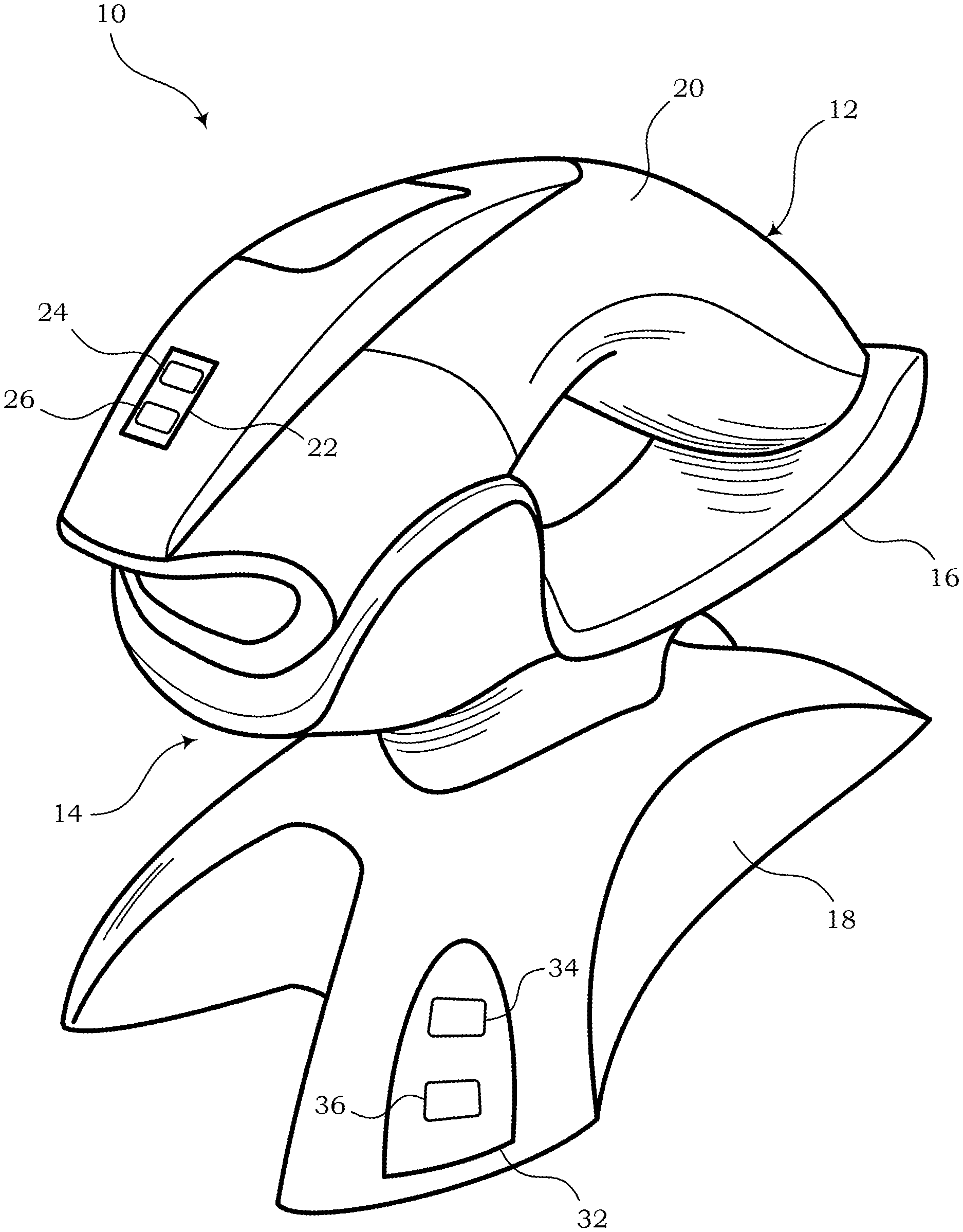
FIG. 1 is a perspective view of an embodiment of a charging system 10. In this embodiment, the charging system 10 includes a wireless electronic device 12 and a recharging device 14. The wireless electronic device 12 may be a handheld device, such as a wireless barcode scanner or laser scanner. In other embodiments, the wireless electronic device 12 may include other types of portable devices, such as wireless landline telephones, electric razors, calculators, flashlights, etc.
The recharging device 14 in the embodiment of FIG. 1 includes a cradle 16 and a base 18. The cradle 16 may be designed to support the wireless electronic device 12 and may include electrical contacts (not shown) for making electrical connection with the wireless electronic device 12. In this manner, electrical power can be provided to the wireless electronic device 12 from the cradle 16 to charge or recharge a rechargeable power supply (not shown) attached externally to a housing 20 of the wireless electronic device 12 or disposed inside the housing 20 of the wireless electronic device 12. The rechargeable power supply may include one or more supercapacitors.
In some embodiments, the wireless electronic device 12 may include a charge status indicator 22 for indicating the charge status of the rechargeable power supply. As shown, the charge status indicator 22 may include a first indicator 24 and a second indicator 26. The first and second indicators 24, 26 may be light emitting diodes (LEDs). According to other embodiments, a second charge status indicator 32 may be incorporated in the base 18. The second charge status indicator 32 may also include a first indicator (e.g., LED) 34 and a second indicator (e.g., LED) 36.
The first and second indicators 24, 26 of the charge status indicator 22 may be positioned in two different locations, as shown, to give the appearance of separate indicators. In an alternative embodiment, the indicators 24, 26 may be located under an opaque window to give the appearance of the same indicator providing two (or more) different colors of light. With an opaque or semi-opaque window, a user would perceive that the light may be coming from the same location and may not notice the difference in the locations of the yellow and green LEDs. Likewise, the first and second indicators 34, 36 of the charge status indicator 32 may also be positioned in different locations (as shown) or under the same opaque window to give the perception of the same location with different colors.
One embodiment may include incorporating the charge status indicator 22 only on the wireless electronic device 12. A second embodiment may include incorporating the charge status indicator 32 only on the base 18. A third embodiment may include incorporating the two charge status indicators 22, 32 on both the wireless electronic device 12 and base 18, respectively.
According to the embodiment of FIG. 1, the base 18 of the recharging device 14 may be configured to hold the cradle 16 above a surface to enable a user to easily engage the wireless electronic device 12 with the cradle 16. Also, the base 18 may include a power cord (not shown) that can be plugged into an electrical outlet, allowing power to be supplied from the outlet to the charging system 10 for charging the rechargeable power supply of the wireless electronic device 12.
FIG. 2 is a top view of an embodiment of the recharging device 14 shown in FIG. 1 with the wireless electronic device 12 removed. In addition to the elements described with respect to FIG. 1, the cradle 16 of the recharging device 14 further comprises electrical contacts 40 for communicating with the wireless electronic device 12 when it is properly seated in the cradle 16. The electrical contacts 40 are configured to provide power to the wireless electronic device 12 for recharging the rechargeable power supply. The electrical contacts 40 are also configured to communicate charge status information from the wireless electronic device 12 to the recharging device 14, particularly with respect to embodiments in which the recharging device 14 includes the charge status indicator 32. The electrical contacts 40 may also be configured to electrically communicate other signals as needed.
The recharging device 14 may further include a power indicator 42 incorporated on the base 18. The power indicator 42 may be configured to indicate when power is being supplied to the recharging device 14 from the electrical outlet allowing the recharging device 14 to properly charge or recharge the rechargeable power supply of the wireless electronic device 12.
FIG. 3 is a perspective view of an embodiment of the wireless electronic device 12 shown in FIG. 1. For example, the wireless electronic device 12 may be a wireless barcode scanner. In addition to the features shown and described with respect to FIG. 1, the wireless electronic device 12 may further include contacts 50 configured for making electrical connection with the electrical contacts 40 of the cradle 16 (FIG. 2). Therefore, when the wireless electronic device 12 is properly seated or nested on the cradle 16, the contacts 50 are configured to touch the electrical contacts 40 of the cradle 16. As mentioned above, when the contacts 40, 50 are connected, electrical power can be provided to the rechargeable power supply as needed for charging or recharging the rechargeable power supply. Also, other communication signals may be shared between the wireless electronic device 12 and the recharging device 14 via the contacts 40, 50.
Therefore, according to one implementation, the charging system 10 (FIGS. 1-3) comprises a handheld electronic device (e.g., wireless electronic device 12) having a rechargeable power supply. The charging system 10 also includes a base charger or recharging device 14 configured to support the handheld electronic device during a charging stage. A charge status indicator (e.g., one or both of charge status indicators 22, 32) comprises first and second LEDs (e.g., LEDs 24, 26 or LEDs 34, 36) and a switching circuit. The base charger is configured to provide electric charge to the handheld electronic device during the charging stage to recharge the rechargeable power supply of the handheld electronic device. The charge status indicator 22, 32 comprises a charge sensor for sensing the charge of the rechargeable power supply. The charge status indicator 22, 32 further comprises a detection device configured to compare the sensed charge of the rechargeable power supply with a plurality of predetermined charge levels in order to determine one of a plurality of capacity ranges of the rechargeable power supply. The switching circuit of the charge status indicator 22, 32 is configured to switch the first and second LEDs (e.g., LEDs 24, 26 or LEDs 34, 36) on and off in one of a plurality of predefined illumination patterns (or on/off patterns) to indicate a capacity range of the rechargeable power supply corresponding to the capacity range determined by the detection device.
In some embodiments, the charge status indicator 32 is incorporated in the base charger (e.g., recharging device 14). In another embodiment, the charge status indicator 22 is incorporated in the handheld electronic device. Specifically, the rechargeable power supply may include at least one supercapacitor. The handheld electronic device may be a wireless barcode scanner.
The plurality of capacity ranges may include a first range designating a "near empty" status, a second range designating a "ready to use" status, a third range designating a "greater than half capacity" status, and a fourth range designating an "at or near full capacity" status. The switching circuit may be configured to switch the first and second LEDs in a first predefined illumination pattern (or on/off pattern) when the charge of the rechargeable power supply falls within the first range, a second predefined illumination pattern when the charge of the rechargeable power supply falls within the second range, a third predefined illumination pattern when the charge of the rechargeable power supply falls within the third range, and a fourth predefined illumination pattern when the charge of the rechargeable power supply falls within the fourth range. In particular, the first predefined illumination pattern may include repeating a cycle of switching the first LED on for about 500 ms and off for about 500 ms. The second predefined illumination pattern may include repeating a cycle of switching the second LED on for about 500 ms and off for about 500 ms. The third predefined illumination pattern may include repeating a cycle of switching the second LED on for about 1000 ms and off for about 500 ms. Also, the fourth predefined illumination pattern may include switching the second LED on.
In one example, the first LED may be a yellow LED and the second LED may be a green LED. The switching circuit may be configured to switch the first and second LEDs off when the base charger is not charging the rechargeable power supply or when the handheld electronic device is not properly supported by the base charger. Furthermore, the switching circuit may be configured to switch at least one of the first and second LEDs in a rapid on/off pattern when at least one of the charge sensor and detection device detects a charging error or a condition in which the charging has been suspended.
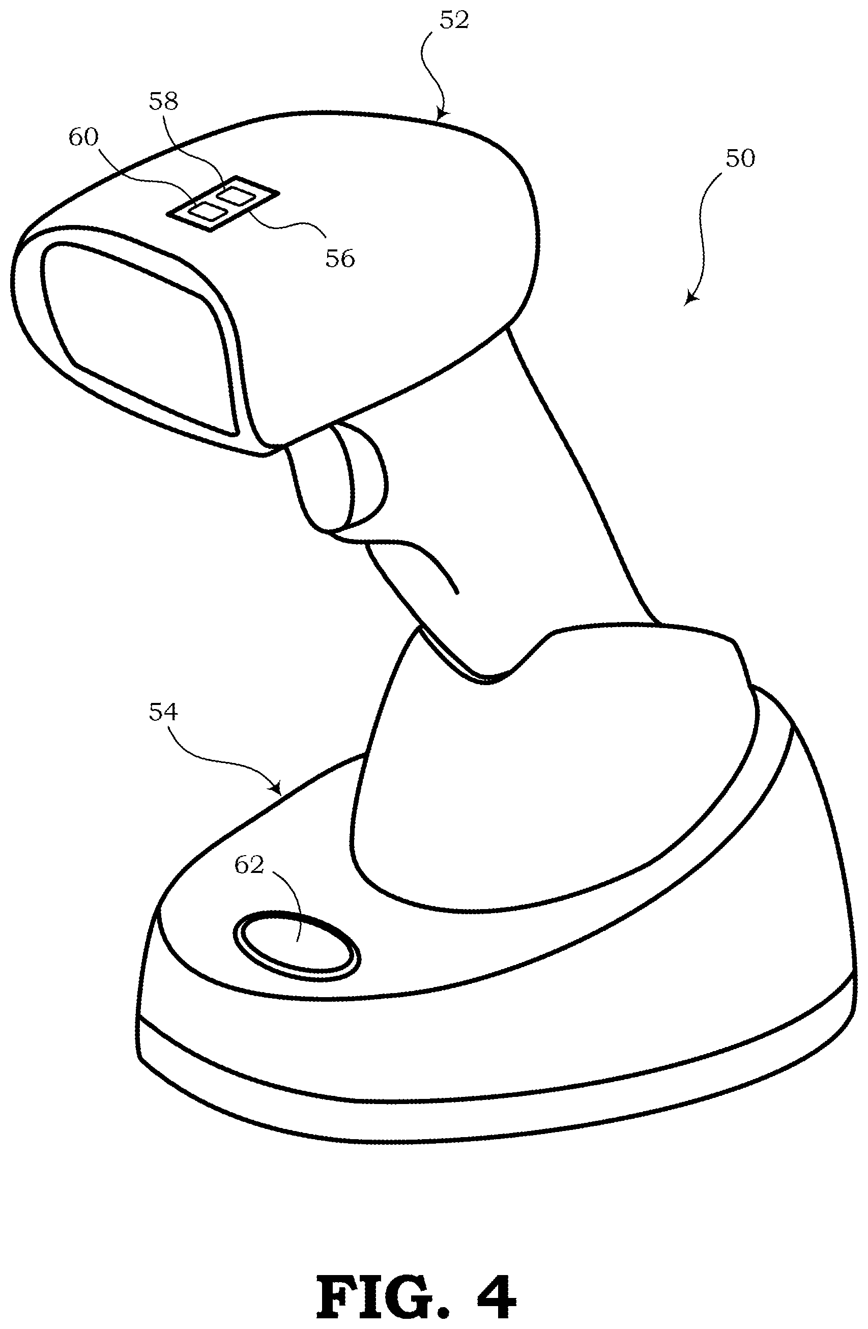
FIG. 4 is a perspective view of a second embodiment of a charging system 50. In this embodiment, the charging system 50 includes a wireless electronic device 52 and a recharging device 54. The wireless electronic device 52 may be a handheld device, such as a wireless barcode scanner or laser scanner. In other embodiments, the wireless electronic device 52 may include other types of portable devices, such as wireless landline telephones, electric razors, calculators, flashlights, etc.
The recharging device 54 in the embodiment of FIG. 4 includes a base that acts as a cradle for supporting the wireless electronic device 52 during charging. The recharging device 54 may be designed to support the wireless electronic device 52 and may include electrical contacts (not shown) for making electrical connection with the wireless electronic device 52. In this manner, electrical power can be provided to the wireless electronic device 52 from the recharging device 54 to charge or recharge a rechargeable power supply (not shown) attached externally to the wireless electronic device 52 or disposed inside a housing of the wireless electronic device 52. The rechargeable power supply may include one or more supercapacitors.
In some embodiments, the wireless electronic device 52 may include a charge status indicator 56 for indicating the charge status of the rechargeable power supply. As shown, the charge status indicator 56 may include a first indicator 58 and a second indicator 60. The first and second indicators 58, 60 may be light emitting diodes (LEDs). According to other embodiments, a second charge status indicator 62 may be incorporated in the recharging device 54. The second charge status indicator 62 may also include first and second LEDs.
One embodiment may include incorporating the charge status indicator 56 only on the wireless electronic device 52. A second embodiment may include incorporating the charge status indicator 62 only on the recharging device 54. A third embodiment may include incorporating the two charge status indicators 56, 62 on both the wireless electronic device 52 and recharging device 54, respectively.
According to the embodiment of FIG. 4, the recharging device 54 may be configured to support the wireless electronic device 52 in an upright manner. Also, the recharging device 54 may include a power cord (not shown) that can be plugged into an electrical outlet, allowing power to be supplied from the outlet to the charging system 50 for charging the rechargeable power supply of the wireless electronic device 52.
The charge status indicator 62 may be built into an oval page button that may be used for paging the wireless electronic device 52. The oval page button may include an opaque or semi-opaque material through which light from one or more indicators may be diffused. One side (e.g., the left side) of the oval page button may comprise the charge status indicator 62, which may include a first indicator (e.g., a green LED) and a second indicator (e.g., a yellow LED) underneath the opaque or semi-opaque material. The user may perceive the color change when one or the other of the indicators is illuminated, but may not necessarily notice the change in the location of the indicators underneath the button. In some embodiments, the other side (e.g., the right side) of the oval page button may include a third indicator (e.g., a red LED) used for other indications, such as a "power on" indication or a paging operation.
FIG. 5 is a block diagram illustrating an embodiment of a charge status indicator 60. The charge status indicator 60 of FIG. 5 may represent an embodiment of the charge status indicator 22 incorporated on the wireless electronic device 12 and/or an embodiment of the charge status indicator 32 incorporated on the recharging device 14. According to some embodiments, portions of the charge status indicator 60 may be incorporated in the wireless electronic device 12 while other portions of the charge status indicator 60 may be incorporated in the recharging device 14.
In this embodiment, the charge status indicator 60 includes a sensor 62, memory 64, a charge level comparing unit 66, an output control unit 68, and output devices 70. The sensor 62 may be a charge sensor for sensing the stored charge of the rechargeable power supply. The memory 64 may be configured to store various charge level values. The charge level comparing unit 66 is configured to compare the charge sensed by the sensor 62 with the various charge level values stored in the memory 64.
Based on the comparison made by the charge level comparing unit 66, the charge level comparing unit 66 and/or the output control unit 68 may be configured to determine one of multiple different ranges within which the sensed charge level lies. Once the range is detected, the output control unit 68 is configured to control the output devices 70 to indicate the detected range to the user.
The output devices 70 may include visual and/or audible indicating devices. For example, the output devices 70 may include two LEDs for visually indicating the charge status. In this sense, the output control unit 68 may be configured as a switching control device for switching the LEDs on and off according to predefined patterns. The predefined patterns may include signals that can intuitively communicate various charge status levels to the user. For instance, the output devices 70 may include a first LED having one color (e.g., yellow) and a second LED having another color (e.g., green).
According to one embodiment, the charge status indicator 60 may include a charge sensing device (e.g., sensor 62) configured to sense the charge of a rechargeable power supply. The charge status indicator 60 may further includes a detection device (e.g., charge level comparing unit 66) configured to compare the sensed charge with a plurality of predetermined levels in order to determine one of a plurality of capacity ranges of the rechargeable power supply. The charge status indicator 60 also include the output devices 70, such as a first LED and a second LED. Also, a switching circuit (e.g., output control unit 68) is configured to switch the first and second LEDs on and off using a plurality of predefined illumination (or on/off) patterns to indicate the capacity range of the rechargeable power supply.
Furthermore, the rechargeable power supply may include at least one supercapacitor and may be incorporated in a wireless barcode scanner. The charge status indicator may additionally or alternatively be incorporated in a cradle (e.g., recharging device 14) that is configured to support the wireless barcode scanner during a charging process, wherein the cradle may be further configured to provide electric charge to the wireless barcode scanner during the charging process to recharge the supercapacitor of the wireless barcode scanner.
The plurality of capacity ranges may include a first range designating a "near empty" status, a second range designating a "ready to use" status, a third range designating a "greater than half capacity" status, and a fourth range designating an "at or near full capacity" status. The switching circuit (e.g., output control unit 68) may be configured to switch the first and second LEDs in a first predefined illumination pattern when the charge of the rechargeable power supply falls within the first range, a second predefined illumination pattern when the charge of the rechargeable power supply falls within the second range, a third predefined illumination pattern when the charge of the rechargeable power supply falls within the third range, and a fourth predefined illumination pattern when the charge of the rechargeable power supply falls within the fourth range. For example, the first predefined illumination pattern may include repeating a cycle of switching the first LED on for about 500 ms and off for about 500 ms, the second predefined illumination pattern may include repeating a cycle of switching the second LED on for about 500 ms and off for about 500 ms, the third predefined illumination pattern may include repeating a cycle of switching the second LED on for about 1000 ms and off for about 500 ms, and the fourth predefined illumination pattern may include switching the second LED on indefinitely.
In addition, the switching circuit (e.g., output control unit 68) may be configured to switch the first and second LEDs off when the base charger is not charging the rechargeable power supply or when the handheld electronic device is not properly supported by the base charger. The switching circuit may also be configured to switch at least one of the first and second LEDs in a rapid on/off pattern when the charge sensing device or detection device detects a charging error or a condition in which the charging process has been suspended.
FIG. 6 is a diagram of a chart 80 showing exemplary implementations of illumination or on/off patterns of the output devices 70 for indicating the status of the rechargeable power supply. The chart 80 defines the signals that may be provided by the output control unit 68 (or switching circuit) for controlling the illumination of the output devices 70 (e.g., LEDs). In this embodiment, the indicators or output devices 70 include a first LED (i.e., "LED #1") and a second LED (i.e., "LED #2"). According to other embodiments, the charge status indicator 60 may include additional LEDs (e.g., three or more LEDs).
According to the chart 80 of FIG. 6, the output control unit 68 is configured to switch the LEDs on and off in predefined patterns depending on the detected status. When the wireless electronic device 12 (e.g., barcode scanner) is absent (i.e., not seated in the cradle 16), both LEDs may be off to indicate a "Scanner Absent" status or other "wireless electronic device absent" status. If a charging error is detected, one or both of the LEDs may be switched on and off in a rapid pattern (e.g., 300 ms on and 300 ms off). This on/off cycle is repeated indefinitely until another condition is detected.
The indicators may also indicate a "near empty" status, which may be indicated by a repeating on/off pattern of LED #1 (e.g., yellow LED), such as a pattern of 500 ms on and 500 ms off. The second LED is switched off. The "near empty" indication may represent a condition in which the rechargeable power supply is currently holding a charge at 0% to about 25% full capacity.
A "ready to use" status may be defined by switching LED #2 (e.g., green LED) repeatedly on and off in a signal pattern of 500 ms high (i.e., on) and 500 ms low (i.e., off). The first LED is switched off during this time. The "ready to use" indication may represent a condition in which the rechargeable power supply is currently holding a charge of about 25% to about 50% of full capacity. As an example, when the rechargeable power supply is a supercapacitor and the wireless electronic device is a barcode scanner, the "ready to use" indication may signal to the user that the barcode scanner can be used to scan at least a few barcodes before the rechargeable power supply needs to be recharged further.
A "half capacity" status may be defined by switching LED #1 off and switching LED #2 on and off in a pattern of one second at a high signal (i.e., on) and 500 ms at a low signal (i.e., off). The "half capacity" indication may represent a condition in which the rechargeable power supply is currently holding a charge of about 50% to about 75% of full capacity.
The status of "full capacity" or "near full capacity" may be defined by switching LED #2 on indefinitely and LED #1 is switched off. The "full capacity" indication may represent a condition in which the rechargeable power supply is currently holding a charge of about 75% to 100% of full capacity.
It should be noted that other embodiments may include different output devices 70 or a different number of LEDs. Other embodiments may also include different colors of LEDs and/or different timing signals for switching the LEDs on and off. Also, other embodiments may be used to indicate different ranges of charges with respect to full capacity.
To supplement the present disclosure, this application incorporates entirely by reference the following commonly assigned patents, patent application publications, and patent applications:
U.S. Pat. Nos. 6,832,725; 7,128,266;
U.S. Pat. Nos. 7,159,783; 7,413,127;
U.S. Pat. Nos. 7,726,575; 8,294,969;
U.S. Pat. Nos. 8,317,105; 8,322,622;
U.S. Pat. Nos. 8,366,005; 8,371,507;
U.S. Pat. Nos. 8,376,233; 8,381,979;
U.S. Pat. Nos. 8,390,909; 8,408,464;
U.S. Pat. Nos. 8,408,468; 8,408,469;
U.S. Pat. Nos. 8,424,768; 8,448,863;
U.S. Pat. Nos. 8,457,013; 8,459,557;
U.S. Pat. Nos. 8,469,272; 8,474,712;
U.S. Pat. Nos. 8,479,992; 8,490,877;
U.S. Pat. Nos. 8,517,271; 8,523,076;
U.S. Pat. Nos. 8,528,818; 8,544,737;
U.S. Pat. Nos. 8,548,242; 8,548,420;
U.S. Pat. Nos. 8,550,335; 8,550,354;
U.S. Pat. Nos. 8,550,357; 8,556,174;
U.S. Pat. Nos. 8,556,176; 8,556,177;
U.S. Pat. Nos. 8,559,767; 8,599,957;
U.S. Pat. Nos. 8,561,895; 8,561,903;
U.S. Pat. Nos. 8,561,905; 8,565,107;
U.S. Pat. Nos. 8,571,307; 8,579,200;
U.S. Pat. Nos. 8,583,924; 8,584,945;
U.S. Pat. Nos. 8,587,595; 8,587,697;
U.S. Pat. Nos. 8,588,869; 8,590,789;
U.S. Pat. Nos. 8,596,539; 8,596,542;
U.S. Pat. Nos. 8,596,543; 8,599,271;
U.S. Pat. Nos. 8,599,957; 8,600,158;
U.S. Pat. Nos. 8,600,167; 8,602,309;
U.S. Pat. Nos. 8,608,053; 8,608,071;
U.S. Pat. Nos. 8,611,309; 8,615,487;
U.S. Pat. Nos. 8,616,454; 8,621,123;
U.S. Pat. Nos. 8,622,303; 8,628,013;
U.S. Pat. Nos. 8,628,015; 8,628,016;
U.S. Pat. Nos. 8,629,926; 8,630,491;
U.S. Pat. Nos. 8,635,309; 8,636,200;
U.S. Pat. Nos. 8,636,212; 8,636,215;
U.S. Pat. Nos. 8,636,224; 8,638,806;
U.S. Pat. Nos. 8,640,958; 8,640,960;
U.S. Pat. Nos. 8,643,717; 8,646,692;
U.S. Pat. Nos. 8,646,694; 8,657,200;
U.S. Pat. Nos. 8,659,397; 8,668,149;
U.S. Pat. Nos. 8,678,285; 8,678,286;
U.S. Pat. Nos. 8,682,077; 8,687,282;
U.S. Pat. Nos. 8,692,927; 8,695,880;
U.S. Pat. Nos. 8,698,949; 8,717,494;
U.S. Pat. Nos. 8,717,494; 8,720,783;
U.S. Pat. Nos. 8,723,804; 8,723,904;
U.S. Pat. Nos. 8,727,223; 8,740,082;
U.S. Pat. Nos. 8,740,085; 8,746,563;
U.S. Pat. Nos. 8,750,445; 8,752,766;
U.S. Pat. Nos. 8,756,059; 8,757,495;
U.S. Pat. Nos. 8,760,563; 8,763,909;
U.S. Pat. Nos. 8,777,108; 8,777,109;
U.S. Pat. Nos. 8,779,898; 8,781,520;
U.S. Pat. Nos. 8,783,573; 8,789,757;
U.S. Pat. Nos. 8,789,758; 8,789,759;
U.S. Pat. Nos. 8,794,520; 8,794,522;
U.S. Pat. Nos. 8,794,525; 8,794,526;
U.S. Pat. Nos. 8,798,367; 8,807,431;
U.S. Pat. Nos. 8,807,432; 8,820,630;
U.S. Pat. Nos. 8,822,848; 8,824,692;
U.S. Pat. Nos. 8,824,696; 8,842,849;
U.S. Pat. Nos. 8,844,822; 8,844,823;
U.S. Pat. Nos. 8,849,019; 8,851,383;
U.S. Pat. Nos. 8,854,633; 8,866,963;
U.S. Pat. Nos. 8,868,421; 8,868,519;
U.S. Pat. Nos. 8,868,802; 8,868,803;
U.S. Pat. Nos. 8,870,074; 8,879,639;
U.S. Pat. Nos. 8,880,426; 8,881,983;
U.S. Pat. Nos. 8,881,987; 8,903,172;
U.S. Pat. Nos. 8,908,995; 8,910,870;
U.S. Pat. Nos. 8,910,875; 8,914,290;
U.S. Pat. Nos. 8,914,788; 8,915,439;
U.S. Pat. Nos. 8,915,444; 8,916,789;
U.S. Pat. Nos. 8,918,250; 8,918,564;
U.S. Pat. Nos. 8,925,818; 8,939,374;
U.S. Pat. Nos. 8,942,480; 8,944,313;
U.S. Pat. Nos. 8,944,327; 8,944,332;
U.S. Pat. Nos. 8,950,678; 8,967,468;
U.S. Pat. Nos. 8,971,346; 8,976,030;
U.S. Pat. Nos. 8,976,368; 8,978,981;
U.S. Pat. Nos. 8,978,983; 8,978,984;
U.S. Pat. Nos. 8,985,456; 8,985,457;
U.S. Pat. Nos. 8,985,459; 8,985,461;
U.S. Pat. Nos. 8,988,578; 8,988,590;
U.S. Pat. Nos. 8,991,704; 8,996,194;
U.S. Pat. Nos. 8,996,384; 9,002,641;
U.S. Pat. Nos. 9,007,368; 9,010,641;
U.S. Pat. Nos. 9,015,513; 9,016,576;
U.S. Pat. Nos. 9,022,288; 9,030,964;
U.S. Pat. Nos. 9,033,240; 9,033,242;
U.S. Pat. Nos. 9,036,054; 9,037,344;
U.S. Pat. Nos. 9,038,911; 9,038,915;
U.S. Pat. Nos. 9,047,098; 9,047,359;
U.S. Pat. Nos. 9,047,420; 9,047,525;
U.S. Pat. Nos. 9,047,531; 9,053,055;
U.S. Pat. Nos. 9,053,378; 9,053,380;
U.S. Pat. Nos. 9,058,526; 9,064,165;
U.S. Pat. Nos. 9,064,165; 9,064,167;
U.S. Pat. Nos. 9,064,168; 9,064,254;
U.S. Pat. Nos. 9,066,032; 9,070,032;
U.S. Pat. Nos. 9,076,459; 9,079,423;
U.S. Pat. Nos. 9,080,856; 9,082,023;
U.S. Pat. Nos. 9,082,031; 9,084,032;
U.S. Pat. Nos. 9,087,250; 9,092,681;
U.S. Pat. Nos. 9,092,682; 9,092,683;
U.S. Pat. Nos. 9,093,141; 9,098,763;
U.S. Pat. Nos. 9,104,929; 9,104,934;
U.S. Pat. Nos. 9,107,484; 9,111,159;
U.S. Pat. Nos. 9,111,166; 9,135,483;
U.S. Pat. Nos. 9,137,009; 9,141,839;
U.S. Pat. Nos. 9,147,096; 9,148,474;
U.S. Pat. Nos. 9,158,000; 9,158,340;
U.S. Pat. Nos. 9,158,953; 9,159,059;
U.S. Pat. Nos. 9,165,174; 9,171,543;
U.S. Pat. Nos. 9,183,425; 9,189,669;
U.S. Pat. Nos. 9,195,844; 9,202,458;
U.S. Pat. Nos. 9,208,366; 9,208,367;
U.S. Pat. Nos. 9,219,836; 9,224,024;
U.S. Pat. Nos. 9,224,027; 9,230,140;
U.S. Pat. Nos. 9,235,553; 9,239,950;
U.S. Pat. Nos. 9,245,492; 9,248,640;
U.S. Pat. Nos. 9,250,652; 9,250,712;
U.S. Pat. Nos. 9,251,411; 9,258,033;
U.S. Pat. Nos. 9,262,633; 9,262,660;
U.S. Pat. Nos. 9,262,662; 9,269,036;
U.S. Pat. Nos. 9,270,782; 9,274,812;
U.S. Pat. Nos. 9,275,388; 9,277,668;
U.S. Pat. Nos. 9,280,693; 9,286,496;
U.S. Pat. Nos. 9,298,964; 9,301,427;
U.S. Pat. Nos. 9,313,377; 9,317,037;
U.S. Pat. Nos. 9,319,548; 9,342,723;
U.S. Pat. Nos. 9,361,882; 9,365,381;
U.S. Pat. Nos. 9,373,018; 9,375,945;
U.S. Pat. Nos. 9,378,403; 9,383,848;
U.S. Pat. Nos. 9,384,374; 9,390,304;
U.S. Pat. Nos. 9,390,596; 9,411,386;
U.S. Pat. Nos. 9,412,242; 9,418,269;
U.S. Pat. Nos. 9,418,270; 9,465,967;
U.S. Pat. Nos. 9,423,318; 9,424,454;
U.S. Pat. Nos. 9,436,860; 9,443,123;
U.S. Pat. Nos. 9,443,222; 9,454,689;
U.S. Pat. Nos. 9,464,885; 9,465,967;
U.S. Pat. Nos. 9,478,983; 9,481,186;
U.S. Pat. Nos. 9,487,113; 9,488,986;
U.S. Pat. Nos. 9,489,782; 9,490,540;
U.S. Pat. Nos. 9,491,729; 9,497,092;
U.S. Pat. Nos. 9,507,974; 9,519,814;
U.S. Pat. Nos. 9,521,331; 9,530,038;
U.S. Pat. Nos. 9,572,901; 9,558,386;
U.S. Pat. Nos. 9,606,581; 9,646,189;
U.S. Pat. Nos. 9,646,191; 9,652,648;
U.S. Pat. Nos. 9,652,653; 9,656,487;
U.S. Pat. Nos. 9,659,198; 9,680,282;
U.S. Pat. Nos. 9,697,401; 9,701,140;
U.S. Design Pat. No. D702,237;
U.S. Design Pat. No. D716,285;
U.S. Design Pat. No. D723,560;
U.S. Design Pat. No. D730,357;
U.S. Design Pat. No. D730,901;
U.S. Design Pat. No. D730,902;
U.S. Design Pat. No. D734,339;
U.S. Design Pat. No. D737,321;
U.S. Design Pat. No. D754,205;
U.S. Design Pat. No. D754,206;
U.S. Design Pat. No. D757,009;
U.S. Design Pat. No. D760,719;
U.S. Design Pat. No. D762,604;
U.S. Design Pat. No. D766,244;
U.S. Design Pat. No. D777,166;
U.S. Design Pat. No. D771,631;
U.S. Design Pat. No. D783,601;
U.S. Design Pat. No. D785,617;
U.S. Design Pat. No. D785,636;
U.S. Design Pat. No. D790,505;
U.S. Design Pat. No. D790,546;
International Publication No. 2013/163789;
U.S. Patent Application Publication No. 2008/0185432;
U.S. Patent Application Publication No. 2009/0134221;
U.S. Patent Application Publication No. 2010/0177080;
U.S. Patent Application Publication No. 2010/0177076;
U.S. Patent Application Publication No. 2010/0177707;
U.S. Patent Application Publication No. 2010/0177749;
U.S. Patent Application Publication No. 2010/0265880;
U.S. Patent Application Publication No. 2011/0202554;
U.S. Patent Application Publication No. 2012/0111946;
U.S. Patent Application Publication No. 2012/0168511;
U.S. Patent Application Publication No. 2012/0168512;
U.S. Patent Application Publication No. 2012/0193423;
U.S. Patent Application Publication No. 2012/0194692;
U.S. Patent Application Publication No. 2012/0203647;
U.S. Patent Application Publication No. 2012/0223141;
U.S. Patent Application Publication No. 2012/0228382;
U.S. Patent Application Publication No. 2012/0248188;
U.S. Patent Application Publication No. 2013/0043312;
U.S. Patent Application Publication No. 2013/0082104;
U.S. Patent Application Publication No. 2013/0175341;
U.S. Patent Application Publication No. 2013/0175343;
U.S. Patent Application Publication No. 2013/0257744;
U.S. Patent Application Publication No. 2013/0257759;
U.S. Patent Application Publication No. 2013/0270346;
U.S. Patent Application Publication No. 2013/0292475;
U.S. Patent Application Publication No. 2013/0292477;
U.S. Patent Application Publication No. 2013/0293539;
U.S. Patent Application Publication No. 2013/0293540;
U.S. Patent Application Publication No. 2013/0306728;
U.S. Patent Application Publication No. 2013/0306731;
U.S. Patent Application Publication No. 2013/0307964;
U.S. Patent Application Publication No. 2013/0308625;
U.S. Patent Application Publication No. 2013/0313324;
U.S. Patent Application Publication No. 2013/0332996;
U.S. Patent Application Publication No. 2014/0001267;
U.S. Patent Application Publication No. 2014/0025584;
U.S. Patent Application Publication No. 2014/0034734;
U.S. Patent Application Publication No. 2014/0036848;
U.S. Patent Application Publication No. 2014/0039693;
U.S. Patent Application Publication No. 2014/0049120;
U.S. Patent Application Publication No. 2014/0049635;
U.S. Patent Application Publication No. 2014/0061306;
U.S. Patent Application Publication No. 2014/0063289;
U.S. Patent Application Publication No. 2014/0066136;
U.S. Patent Application Publication No. 2014/0067692;
U.S. Patent Application Publication No. 2014/0070005;
U.S. Patent Application Publication No. 2014/0071840;
U.S. Patent Application Publication No. 2014/0074746;
U.S. Patent Application Publication No. 2014/0076974;
U.S. Patent Application Publication No. 2014/0097249;
U.S. Patent Application Publication No. 2014/0098792;
U.S. Patent Application Publication No. 2014/0100813;
U.S. Patent Application Publication No. 2014/0103115;
U.S. Patent Application Publication No. 2014/0104413;
U.S. Patent Application Publication No. 2014/0104414;
U.S. Patent Application Publication No. 2014/0104416;
U.S. Patent Application Publication No. 2014/0106725;
U.S. Patent Application Publication No. 2014/0108010;
U.S. Patent Application Publication No. 2014/0108402;
U.S. Patent Application Publication No. 2014/0110485;
U.S. Patent Application Publication No. 2014/0125853;
U.S. Patent Application Publication No. 2014/0125999;
U.S. Patent Application Publication No. 2014/0129378;
U.S. Patent Application Publication No. 2014/0131443;
U.S. Patent Application Publication No. 2014/0133379;
U.S. Patent Application Publication No. 2014/0136208;
U.S. Patent Application Publication No. 2014/0140585;
U.S. Patent Application Publication No. 2014/0152882;
U.S. Patent Application Publication No. 2014/0158770;
U.S. Patent Application Publication No. 2014/0159869;
U.S. Patent Application Publication No. 2014/0166759;
U.S. Patent Application Publication No. 2014/0168787;
U.S. Patent Application Publication No. 2014/0175165;
U.S. Patent Application Publication No. 2014/0191684;
U.S. Patent Application Publication No. 2014/0191913;
U.S. Patent Application Publication No. 2014/0197304;
U.S. Patent Application Publication No. 2014/0214631;
U.S. Patent Application Publication No. 2014/0217166;
U.S. Patent Application Publication No. 2014/0231500;
U.S. Patent Application Publication No. 2014/0247315;
U.S. Patent Application Publication No. 2014/0263493;
U.S. Patent Application Publication No. 2014/0263645;
U.S. Patent Application Publication No. 2014/0270196;
U.S. Patent Application Publication No. 2014/0270229;
U.S. Patent Application Publication No. 2014/0278387;
U.S. Patent Application Publication No. 2014/0288933;
U.S. Patent Application Publication No. 2014/0297058;
U.S. Patent Application Publication No. 2014/0299665;
U.S. Patent Application Publication No. 2014/0332590;
U.S. Patent Application Publication No. 2014/0351317;
U.S. Patent Application Publication No. 2014/0362184;
U.S. Patent Application Publication No. 2014/0363015;
U.S. Patent Application Publication No. 2014/0369511;
U.S. Patent Application Publication No. 2014/0374483;
U.S. Patent Application Publication No. 2014/0374485;
U.S. Patent Application Publication No. 2015/0001301;
U.S. Patent Application Publication No. 2015/0001304;
U.S. Patent Application Publication No. 2015/0009338;
U.S. Patent Application Publication No. 2015/0014416;
U.S. Patent Application Publication No. 2015/0021397;
U.S. Patent Application Publication No. 2015/0028104;
U.S. Patent Application Publication No. 2015/0029002;
U.S. Patent Application Publication No. 2015/0032709;
U.S. Patent Application Publication No. 2015/0039309;
U.S. Patent Application Publication No. 2015/0039878;
U.S. Patent Application Publication No. 2015/0040378;
U.S. Patent Application Publication No. 2015/0049347;
U.S. Patent Application Publication No. 2015/0051992;
U.S. Patent Application Publication No. 2015/0053769;
U.S. Patent Application Publication No. 2015/0062366;
U.S. Patent Application Publication No. 2015/0063215;
U.S. Patent Application Publication No. 2015/0088522;
U.S. Patent Application Publication No. 2015/0096872;
U.S. Patent Application Publication No. 2015/0100196;
U.S. Patent Application Publication No. 2015/0102109;
U.S. Patent Application Publication No. 2015/0115035;
U.S. Patent Application Publication No. 2015/0127791;
U.S. Patent Application Publication No. 2015/0128116;
U.S. Patent Application Publication No. 2015/0133047;
U.S. Patent Application Publication No. 2015/0134470;
U.S. Patent Application Publication No. 2015/0136851;
U.S. Patent Application Publication No. 2015/0142492;
U.S. Patent Application Publication No. 2015/0144692;
U.S. Patent Application Publication No. 2015/0144698;
U.S. Patent Application Publication No. 2015/0149946;
U.S. Patent Application Publication No. 2015/0161429;
U.S. Patent Application Publication No. 2015/0178523;
U.S. Patent Application Publication No. 2015/0178537;
U.S. Patent Application Publication No. 2015/0178685;
U.S. Patent Application Publication No. 2015/0181109;
U.S. Patent Application Publication No. 2015/0199957;
U.S. Patent Application Publication No. 2015/0210199;
U.S. Patent Application Publication No. 2015/0212565;
U.S. Patent Application Publication No. 2015/0213647;
U.S. Patent Application Publication No. 2015/0220753;
U.S. Patent Application Publication No. 2015/0220901;
U.S. Patent Application Publication No. 2015/0227189;
U.S. Patent Application Publication No. 2015/0236984;
U.S. Patent Application Publication No. 2015/0239348;
U.S. Patent Application Publication No. 2015/0242658;
U.S. Patent Application Publication No. 2015/0248572;
U.S. Patent Application Publication No. 2015/0254485;
U.S. Patent Application Publication No. 2015/0261643;
U.S. Patent Application Publication No. 2015/0264624;
U.S. Patent Application Publication No. 2015/0268971;
U.S. Patent Application Publication No. 2015/0269402;
U.S. Patent Application Publication No. 2015/0288689;
U.S. Patent Application Publication No. 2015/0288896;
U.S. Patent Application Publication No. 2015/0310243;
U.S. Patent Application Publication No. 2015/0310244;
U.S. Patent Application Publication No. 2015/0310389;
U.S. Patent Application Publication No. 2015/0312780;
U.S. Patent Application Publication No. 2015/0327012;
U.S. Patent Application Publication No. 2016/0014251;
U.S. Patent Application Publication No. 2016/0025697;
U.S. Patent Application Publication No. 2016/0026838;
U.S. Patent Application Publication No. 2016/0026839;
U.S. Patent Application Publication No. 2016/0040982;
U.S. Patent Application Publication No. 2016/0042241;
U.S. Patent Application Publication No. 2016/0057230;
U.S. Patent Application Publication No. 2016/0062473;
U.S. Patent Application Publication No. 2016/0070944;
U.S. Patent Application Publication No. 2016/0092805;
U.S. Patent Application Publication No. 2016/0101936;
U.S. Patent Application Publication No. 2016/0104019;
U.S. Patent Application Publication No. 2016/0104274;
U.S. Patent Application Publication No. 2016/0109219;
U.S. Patent Application Publication No. 2016/0109220;
U.S. Patent Application Publication No. 2016/0109224;
U.S. Patent Application Publication No. 2016/0112631;
U.S. Patent Application Publication No. 2016/0112643;
U.S. Patent Application Publication No. 2016/0117627;
U.S. Patent Application Publication No. 2016/0124516;
U.S. Patent Application Publication No. 2016/0125217;
U.S. Patent Application Publication No. 2016/0125342;
U.S. Patent Application Publication No. 2016/0125873;
U.S. Patent Application Publication No. 2016/0133253;
U.S. Patent Application Publication No. 2016/0171597;
U.S. Patent Application Publication No. 2016/0171666;
U.S. Patent Application Publication No. 2016/0171720;
U.S. Patent Application Publication No. 2016/0171775;
U.S. Patent Application Publication No. 2016/0171777;
U.S. Patent Application Publication No. 2016/0174674;
U.S. Patent Application Publication No. 2016/0178479;
U.S. Patent Application Publication No. 2016/0178685;
U.S. Patent Application Publication No. 2016/0178707;
U.S. Patent Application Publication No. 2016/0179132;
U.S. Patent Application Publication No. 2016/0179143;
U.S. Patent Application Publication No. 2016/0179368;
U.S. Patent Application Publication No. 2016/0179378;
U.S. Patent Application Publication No. 2016/0180130;
U.S. Patent Application Publication No. 2016/0180133;
U.S. Patent Application Publication No. 2016/0180136;
U.S. Patent Application Publication No. 2016/0180594;
U.S. Patent Application Publication No. 2016/0180663;
U.S. Patent Application Publication No. 2016/0180678;
U.S. Patent Application Publication No. 2016/0180713;
U.S. Patent Application Publication No. 2016/0185136;
U.S. Patent Application Publication No. 2016/0185291;
U.S. Patent Application Publication No. 2016/0186926;
U.S. Patent Application Publication No. 2016/0188861;
U.S. Patent Application Publication No. 2016/0188939;
U.S. Patent Application Publication No. 2016/0188940;
U.S. Patent Application Publication No. 2016/0188941;
U.S. Patent Application Publication No. 2016/0188942;
U.S. Patent Application Publication No. 2016/0188943;
U.S. Patent Application Publication No. 2016/0188944;
U.S. Patent Application Publication No. 2016/0189076;
U.S. Patent Application Publication No. 2016/0189087;
U.S. Patent Application Publication No. 2016/0189088;
U.S. Patent Application Publication No. 2016/0189092;
U.S. Patent Application Publication No. 2016/0189284;
U.S. Patent Application Publication No. 2016/0189288;
U.S. Patent Application Publication No. 2016/0189366;
U.S. Patent Application Publication No. 2016/0189443;
U.S. Patent Application Publication No. 2016/0189447;
U.S. Patent Application Publication No. 2016/0189489;
U.S. Patent Application Publication No. 2016/0192051;
U.S. Patent Application Publication No. 2016/0202951;
U.S. Patent Application Publication No. 2016/0202958;
U.S. Patent Application Publication No. 2016/0202959;
U.S. Patent Application Publication No. 2016/0203021;
U.S. Patent Application Publication No. 2016/0203429;
U.S. Patent Application Publication No. 2016/0203797;
U.S. Patent Application Publication No. 2016/0203820;
U.S. Patent Application Publication No. 2016/0204623;
U.S. Patent Application Publication No. 2016/0204636;
U.S. Patent Application Publication No. 2016/0204638;
U.S. Patent Application Publication No. 2016/0227912;
U.S. Patent Application Publication No. 2016/0232891;
U.S. Patent Application Publication No. 2016/0292477;
U.S. Patent Application Publication No. 2016/0294779;
U.S. Patent Application Publication No. 2016/0306769;
U.S. Patent Application Publication No. 2016/0314276;
U.S. Patent Application Publication No. 2016/0314294;
U.S. Patent Application Publication No. 2016/0316190;
U.S. Patent Application Publication No. 2016/0323310;
U.S. Patent Application Publication No. 2016/0325677;
U.S. Patent Application Publication No. 2016/0327614;
U.S. Patent Application Publication No. 2016/0327930;
U.S. Patent Application Publication No. 2016/0328762;
U.S. Patent Application Publication No. 2016/0330218;
U.S. Patent Application Publication No. 2016/0343163;
U.S. Patent Application Publication No. 2016/0343176;
U.S. Patent Application Publication No. 2016/0364914;
U.S. Patent Application Publication No. 2016/0370220;
U.S. Patent Application Publication No. 2016/0372282;
U.S. Patent Application Publication No. 2016/0373847;
U.S. Patent Application Publication No. 2016/0377414;
U.S. Patent Application Publication No. 2016/0377417;
U.S. Patent Application Publication No. 2017/0010141;
U.S. Patent Application Publication No. 2017/0010328;
U.S. Patent Application Publication No. 2017/0010780;
U.S. Patent Application Publication No. 2017/0016714;
U.S. Patent Application Publication No. 2017/0018094;
U.S. Patent Application Publication No. 2017/0046603;
U.S. Patent Application Publication No. 2017/0047864;
U.S. Patent Application Publication No. 2017/0053146;
U.S. Patent Application Publication No. 2017/0053147;
U.S. Patent Application Publication No. 2017/0053647;
U.S. Patent Application Publication No. 2017/0055606;
U.S. Patent Application Publication No. 2017/0060316;
U.S. Patent Application Publication No. 2017/0061961;
U.S. Patent Application Publication No. 2017/0064634;
U.S. Patent Application Publication No. 2017/0083730;
U.S. Patent Application Publication No. 2017/0091502;
U.S. Patent Application Publication No. 2017/0091706;
U.S. Patent Application Publication No. 2017/0091741;
U.S. Patent Application Publication No. 2017/0091904;
U.S. Patent Application Publication No. 2017/0092908;
U.S. Patent Application Publication No. 2017/0094238;
U.S. Patent Application Publication No. 2017/0098947;
U.S. Patent Application Publication No. 2017/0100949;
U.S. Patent Application Publication No. 2017/0108838;
U.S. Patent Application Publication No. 2017/0108895;
U.S. Patent Application Publication No. 2017/0118355;
U.S. Patent Application Publication No. 2017/0123598;
U.S. Patent Application Publication No. 2017/0124369;
U.S. Patent Application Publication No. 2017/0124396;
U.S. Patent Application Publication No. 2017/0124687;
U.S. Patent Application Publication No. 2017/0126873;
U.S. Patent Application Publication No. 2017/0126904;
U.S. Patent Application Publication No. 2017/0139012;
U.S. Patent Application Publication No. 2017/0140329;
U.S. Patent Application Publication No. 2017/0140731;
U.S. Patent Application Publication No. 2017/0147847;
U.S. Patent Application Publication No. 2017/0150124;
U.S. Patent Application Publication No. 2017/0169198;
U.S. Patent Application Publication No. 2017/0171035;
U.S. Patent Application Publication No. 2017/0171703;
U.S. Patent Application Publication No. 2017/0171803;
U.S. Patent Application Publication No. 2017/0180359;
U.S. Patent Application Publication No. 2017/0180577;
U.S. Patent Application Publication No. 2017/0181299;
U.S. Patent Application Publication No. 2017/0190192;
U.S. Patent Application Publication No. 2017/0193432;
U.S. Patent Application Publication No. 2017/0193461;
U.S. Patent Application Publication No. 2017/0193727;
U.S. Patent Application Publication No. 2017/0199266;
U.S. Patent Application Publication No. 2017/0200108; and
U.S. Patent Application Publication No. 2017/0200275.
In the specification and/or figures, typical embodiments of the invention have been disclosed. The present invention is not limited to such exemplary embodiments. The use of the term "and/or" includes any and all combinations of one or more of the associated listed items. The figures are schematic representations and so are not necessarily drawn to scale. Unless otherwise noted, specific terms have been used in a generic and descriptive sense and not for purposes of limitation.
* * * * *
D00000
D00001
D00002
D00003
D00004
XML
uspto.report is an independent third-party trademark research tool that is not affiliated, endorsed, or sponsored by the United States Patent and Trademark Office (USPTO) or any other governmental organization. The information provided by uspto.report is based on publicly available data at the time of writing and is intended for informational purposes only.
While we strive to provide accurate and up-to-date information, we do not guarantee the accuracy, completeness, reliability, or suitability of the information displayed on this site. The use of this site is at your own risk. Any reliance you place on such information is therefore strictly at your own risk.
All official trademark data, including owner information, should be verified by visiting the official USPTO website at www.uspto.gov. This site is not intended to replace professional legal advice and should not be used as a substitute for consulting with a legal professional who is knowledgeable about trademark law.