Intervertebral implant inserter and related methods
Frasier , et al. January 12, 2
U.S. patent number 10,888,433 [Application Number 15/478,305] was granted by the patent office on 2021-01-12 for intervertebral implant inserter and related methods. This patent grant is currently assigned to DePuy Synthes Products, Inc.. The grantee listed for this patent is DePuy Synthes Products, Inc.. Invention is credited to William Frasier, Paul S. Maguire, Thomas Martin, Sean Saidha.


View All Diagrams
| United States Patent | 10,888,433 |
| Frasier , et al. | January 12, 2021 |
Intervertebral implant inserter and related methods
Abstract
An insertion instrument is configured to attach and secure to an expandable implant. The insertion instrument includes a securement member that is configured to be secured to the implant both when the implant is in a collapsed configuration and when the implant is in an expanded configuration. The insertion instrument further includes a drive member that is configured to actuate the implant to the expanded configuration.
| Inventors: | Frasier; William (New Bedford, MA), Saidha; Sean (Franklin, MA), Martin; Thomas (Riverside, RI), Maguire; Paul S. (Hope Valley, RI) | ||||||||||
|---|---|---|---|---|---|---|---|---|---|---|---|
| Applicant: |
|
||||||||||
| Assignee: | DePuy Synthes Products, Inc.
(Raynham, MA) |
||||||||||
| Family ID: | 1000005293939 | ||||||||||
| Appl. No.: | 15/478,305 | ||||||||||
| Filed: | April 4, 2017 |
Prior Publication Data
| Document Identifier | Publication Date | |
|---|---|---|
| US 20180161171 A1 | Jun 14, 2018 | |
Related U.S. Patent Documents
| Application Number | Filing Date | Patent Number | Issue Date | ||
|---|---|---|---|---|---|
| 15378724 | Dec 14, 2016 | ||||
| Current U.S. Class: | 1/1 |
| Current CPC Class: | A61F 2/4611 (20130101); A61F 2/447 (20130101); A61F 2002/30904 (20130101); A61F 2002/30515 (20130101); A61F 2/4603 (20130101); A61F 2002/30507 (20130101); A61F 2002/4627 (20130101); A61F 2002/30411 (20130101); A61F 2002/30556 (20130101); A61F 2002/30405 (20130101); A61F 2002/3039 (20130101) |
| Current International Class: | A61F 2/46 (20060101); A61F 2/44 (20060101); A61F 2/30 (20060101) |
References Cited [Referenced By]
U.S. Patent Documents
| 1802560 | April 1931 | Kerwin |
| 1924695 | August 1933 | Olson |
| 1965653 | July 1934 | Kennedy |
| 2077804 | April 1937 | Morrison |
| 2115250 | April 1938 | Bruson |
| 2121193 | June 1938 | Hanicke |
| 2170111 | August 1939 | Bruson |
| 2173655 | September 1939 | Neracher et al. |
| 2229024 | January 1941 | Bruson |
| 2243717 | May 1941 | Godoy Moreira |
| 2381050 | August 1945 | Hardinge |
| 2388056 | October 1945 | Hendricks |
| 2485531 | October 1949 | William et al. |
| 2489870 | November 1949 | Dzus |
| 2570465 | October 1951 | Lundholm |
| 2677369 | May 1954 | Knowles |
| 2706701 | April 1955 | Hans et al. |
| 2710277 | June 1955 | Shelanski et al. |
| 2826532 | March 1958 | Hosmer |
| 2900305 | August 1959 | Siggia |
| 2977315 | March 1961 | Scheib et al. |
| 3091237 | May 1963 | Skinner |
| 3112743 | December 1963 | Cochran et al. |
| 3115804 | December 1963 | Johnson |
| 3228828 | January 1966 | Romano |
| 3312139 | April 1967 | Di Cristina |
| 3486505 | December 1969 | Morrison |
| 3489143 | January 1970 | Halloran |
| 3648294 | March 1972 | Shahrestani |
| 3698391 | October 1972 | Mahony |
| 3717655 | February 1973 | Godefroi et al. |
| 3760802 | September 1973 | Fischer et al. |
| 3800788 | April 1974 | White |
| 3805775 | April 1974 | Fischer et al. |
| 3811449 | May 1974 | Gravlee et al. |
| 3842825 | October 1974 | Wagner |
| 3848601 | November 1974 | Ma et al. |
| 3855638 | December 1974 | Pilliar |
| 3867728 | February 1975 | Stubstad et al. |
| 3875595 | April 1975 | Froning |
| 3889665 | June 1975 | Ling et al. |
| 3964480 | June 1976 | Froning |
| 3986504 | October 1976 | Avila |
| 4013071 | March 1977 | Rosenberg |
| 4052988 | October 1977 | Doddi et al. |
| 4091806 | May 1978 | Aginsky |
| 4175555 | November 1979 | Herbert |
| 4236512 | December 1980 | Aginsky |
| 4249435 | February 1981 | Villeneuve |
| 4262665 | April 1981 | Roalstad et al. |
| 4262676 | April 1981 | Jamshidi |
| 4274163 | June 1981 | Malcom et al. |
| 4275717 | June 1981 | Bolesky |
| 4312337 | January 1982 | Donohue |
| 4312353 | January 1982 | Shahbabian |
| 4313434 | February 1982 | Segal |
| 4341206 | July 1982 | Perrett et al. |
| 4349921 | September 1982 | Kuntz |
| 4350151 | September 1982 | Scott |
| 4351069 | September 1982 | Ballintyn et al. |
| 4352883 | October 1982 | Lim |
| 4369790 | January 1983 | McCarthy |
| 4399814 | August 1983 | Pratt et al. |
| 4401112 | August 1983 | Rezaian |
| 4401433 | August 1983 | Luther |
| 4409974 | October 1983 | Freedland |
| 4440921 | April 1984 | Allcock et al. |
| 4449532 | May 1984 | Storz |
| 4451256 | May 1984 | Weikl et al. |
| 4456005 | June 1984 | Lichty |
| 4462394 | July 1984 | Jacobs |
| 4463753 | August 1984 | Gustilo |
| 4466435 | August 1984 | Murray |
| 4467479 | August 1984 | Brody |
| 4488543 | December 1984 | Tornier |
| 4488549 | December 1984 | Lee et al. |
| 4494535 | January 1985 | Haig |
| 4495174 | January 1985 | Allcock et al. |
| 4532660 | August 1985 | Field |
| 4537185 | August 1985 | Stednitz |
| 4542539 | September 1985 | Rowe et al. |
| 4545374 | October 1985 | Jacobson |
| 4562598 | January 1986 | Kranz |
| 4573448 | March 1986 | Kambin |
| 4595006 | June 1986 | Burke et al. |
| 4601710 | July 1986 | Moll |
| 4625722 | December 1986 | Murray |
| 4625725 | December 1986 | Davison et al. |
| 4627434 | December 1986 | Murray |
| 4628945 | December 1986 | Johnson, Jr. |
| 4629450 | December 1986 | Suzuki et al. |
| 4630616 | December 1986 | Tretinyak |
| 4632101 | December 1986 | Freedland |
| 4640271 | February 1987 | Lower |
| 4641640 | February 1987 | Griggs |
| 4645503 | February 1987 | Lin et al. |
| 4651717 | March 1987 | Jakubczak |
| 4653489 | March 1987 | Tronzo |
| 4665906 | May 1987 | Jervis |
| 4667663 | May 1987 | Miyata |
| 4686973 | August 1987 | Frisch |
| 4686984 | August 1987 | Bonnet |
| 4688561 | August 1987 | Reese |
| 4697584 | October 1987 | Haynes |
| 4706670 | November 1987 | Andersen et al. |
| 4714469 | December 1987 | Kenna |
| 4714478 | December 1987 | Fischer |
| 4721103 | January 1988 | Freedland |
| 4723544 | February 1988 | Moore et al. |
| 4743256 | May 1988 | Brantigan |
| 4743257 | May 1988 | Toermaelae et al. |
| 4759766 | July 1988 | Buettner-Janz et al. |
| 4760843 | August 1988 | Fischer et al. |
| 4772287 | September 1988 | Ray et al. |
| 4790304 | December 1988 | Rosenberg |
| 4790817 | December 1988 | Luther |
| 4796612 | January 1989 | Reese |
| 4802479 | February 1989 | Haber et al. |
| 4815909 | March 1989 | Simons |
| 4827917 | May 1989 | Brumfield |
| 4834069 | May 1989 | Umeda |
| 4838282 | June 1989 | Strasser et al. |
| 4858601 | August 1989 | Glisson |
| 4862891 | September 1989 | Smith |
| 4863476 | September 1989 | Shepperd |
| 4870153 | September 1989 | Matzner et al. |
| 4871366 | October 1989 | Von et al. |
| 4873976 | October 1989 | Schreiber |
| 4878915 | November 1989 | Brantigan |
| 4880622 | November 1989 | Allcock et al. |
| 4888022 | December 1989 | Huebsch |
| 4888024 | December 1989 | Powlan |
| 4892550 | January 1990 | Huebsch |
| 4896662 | January 1990 | Noble |
| 4898186 | February 1990 | Ikada et al. |
| 4898577 | February 1990 | Badger et al. |
| 4903692 | February 1990 | Reese |
| 4904261 | February 1990 | Dove et al. |
| 4911718 | March 1990 | Lee et al. |
| 4917554 | April 1990 | Bronn |
| 4932969 | June 1990 | Frey et al. |
| 4940467 | July 1990 | Tronzo |
| 4941466 | July 1990 | Romano |
| 4946378 | August 1990 | Hirayama et al. |
| 4959064 | September 1990 | Engelhardt |
| 4961740 | October 1990 | Ray et al. |
| 4963144 | October 1990 | Huene |
| 4966587 | October 1990 | Baumgart |
| 4968317 | November 1990 | Toermaelae et al. |
| 4969888 | November 1990 | Scholten et al. |
| 4978334 | December 1990 | Toye et al. |
| 4978349 | December 1990 | Frigg |
| 4981482 | January 1991 | Ichikawa |
| 4988351 | January 1991 | Paulos et al. |
| 4994027 | February 1991 | Farrell |
| 5002557 | March 1991 | Hasson |
| 5011484 | April 1991 | Breard |
| 5013315 | May 1991 | Barrows |
| 5013316 | May 1991 | Goble et al. |
| 5015247 | May 1991 | Michelson |
| 5015255 | May 1991 | Kuslich |
| 5030233 | July 1991 | Ducheyne |
| 5051189 | September 1991 | Farrah |
| 5053035 | October 1991 | McLaren |
| 5055104 | October 1991 | Ray |
| 5059193 | October 1991 | Kuslich |
| 5062849 | November 1991 | Schelhas |
| 5071435 | December 1991 | Fuchs et al. |
| 5071437 | December 1991 | Steffee |
| 5080662 | January 1992 | Paul |
| 5084043 | January 1992 | Hertzmann et al. |
| 5092891 | March 1992 | Kummer et al. |
| 5098241 | March 1992 | Aldridge et al. |
| 5098433 | March 1992 | Freedland |
| 5098435 | March 1992 | Stednitz et al. |
| 5102413 | April 1992 | Poddar |
| 5108404 | April 1992 | Scholten et al. |
| 5114407 | May 1992 | Burbank |
| 5116336 | May 1992 | Frigg |
| 5120171 | June 1992 | Lasner |
| 5122130 | June 1992 | Keller |
| 5122133 | June 1992 | Evans |
| 5122141 | June 1992 | Simpson et al. |
| 5123926 | June 1992 | Pisharodi |
| 5133755 | July 1992 | Brekke |
| 5134477 | July 1992 | Knauer et al. |
| 5139486 | August 1992 | Moss |
| 5147366 | September 1992 | Arroyo et al. |
| 5158543 | October 1992 | Lazarus |
| 5163989 | November 1992 | Campbell et al. |
| 5167663 | December 1992 | Brumfield |
| 5167664 | December 1992 | Hodorek |
| 5167665 | December 1992 | McKinney |
| 5169400 | December 1992 | Muehling et al. |
| 5171278 | December 1992 | Pisharodi |
| 5171279 | December 1992 | Mathews |
| 5171280 | December 1992 | Baumgartner |
| 5176651 | January 1993 | Allgood et al. |
| 5176683 | January 1993 | Kimsey et al. |
| 5176692 | January 1993 | Wilk et al. |
| 5176697 | January 1993 | Hasson et al. |
| 5178501 | January 1993 | Carstairs |
| 5183052 | February 1993 | Terwilliger |
| 5183464 | February 1993 | Dubrul et al. |
| 5188118 | February 1993 | Terwilliger |
| 5192327 | March 1993 | Brantigan |
| 5195506 | March 1993 | Hulfish |
| 5201742 | April 1993 | Hasson |
| 5217462 | June 1993 | Asnis et al. |
| 5217486 | June 1993 | Rice et al. |
| 5224952 | July 1993 | Deniega et al. |
| 5228441 | July 1993 | Lundquist |
| 5234431 | August 1993 | Keller |
| 5241972 | September 1993 | Bonati |
| 5242410 | September 1993 | Melker |
| 5242447 | September 1993 | Borzone |
| 5242448 | September 1993 | Pettine et al. |
| 5242879 | September 1993 | Abe et al. |
| 5246441 | September 1993 | Ross et al. |
| 5250049 | October 1993 | Michael |
| 5257632 | November 1993 | Turkel et al. |
| 5263953 | November 1993 | Bagby |
| 5269797 | December 1993 | Bonati et al. |
| 5280782 | January 1994 | Wilk |
| 5285795 | February 1994 | Ryan et al. |
| 5286001 | February 1994 | Rafeld |
| 5290243 | March 1994 | Chodorow et al. |
| 5290312 | March 1994 | Kojimoto et al. |
| 5300074 | April 1994 | Frigg |
| 5303718 | April 1994 | Krajicek |
| 5304142 | April 1994 | Liebl et al. |
| 5306307 | April 1994 | Senter et al. |
| 5306308 | April 1994 | Gross et al. |
| 5306309 | April 1994 | Wagner et al. |
| 5306310 | April 1994 | Siebels |
| 5308327 | May 1994 | Heaven et al. |
| 5308352 | May 1994 | Koutrouvelis |
| 5312410 | May 1994 | Miller et al. |
| 5312417 | May 1994 | Wilk |
| 5314477 | May 1994 | Marnay |
| 5322505 | June 1994 | Krause et al. |
| 5324261 | June 1994 | Amundson et al. |
| 5330429 | July 1994 | Noguchi et al. |
| 5331975 | July 1994 | Bonutti |
| 5334184 | August 1994 | Bimman |
| 5334204 | August 1994 | Clewett et al. |
| 5342365 | August 1994 | Waldman |
| 5342382 | August 1994 | Brinkerhoff et al. |
| 5344252 | September 1994 | Kakimoto |
| 5354298 | October 1994 | Lee et al. |
| 5361752 | November 1994 | Moll et al. |
| 5364398 | November 1994 | Chapman et al. |
| 5370646 | December 1994 | Reese et al. |
| 5370647 | December 1994 | Graber et al. |
| 5370661 | December 1994 | Branch |
| 5370697 | December 1994 | Baumgartner |
| 5372660 | December 1994 | Davidson et al. |
| 5374267 | December 1994 | Siegal |
| 5382248 | January 1995 | Jacobson et al. |
| 5383932 | January 1995 | Wilson et al. |
| 5385151 | January 1995 | Scarfone et al. |
| 5387213 | February 1995 | Breard et al. |
| 5387215 | February 1995 | Fisher |
| 5390683 | February 1995 | Pisharodi |
| 5395317 | March 1995 | Kambin |
| 5395371 | March 1995 | Miller et al. |
| 5397364 | March 1995 | Kozak et al. |
| 5401269 | March 1995 | Buettner-Janz et al. |
| 5407430 | April 1995 | Peters |
| 5410016 | April 1995 | Hubbell et al. |
| 5415661 | May 1995 | Holmes |
| 5423816 | June 1995 | Lin |
| 5423817 | June 1995 | Lin |
| 5423850 | June 1995 | Berger |
| 5424773 | June 1995 | Saito |
| 5425773 | June 1995 | Boyd et al. |
| 5431658 | July 1995 | Moskovich |
| 5441538 | August 1995 | Bonutti |
| 5443514 | August 1995 | Steffee |
| 5449359 | September 1995 | Groiso |
| 5449361 | September 1995 | Preissman |
| 5452748 | September 1995 | Simmons et al. |
| 5454365 | October 1995 | Bonutti |
| 5454790 | October 1995 | Dubrul |
| 5454827 | October 1995 | Aust et al. |
| 5456686 | October 1995 | Klapper et al. |
| 5458641 | October 1995 | Ramirez Jimenez |
| 5458643 | October 1995 | Oka et al. |
| 5462563 | October 1995 | Shearer et al. |
| 5464427 | November 1995 | Curtis et al. |
| 5468245 | November 1995 | Vargas, III |
| 5470333 | November 1995 | Ray |
| 5472426 | December 1995 | Bonati et al. |
| 5474539 | December 1995 | Costa et al. |
| 5480400 | January 1996 | Berger |
| 5484437 | January 1996 | Michelson |
| 5486190 | January 1996 | Green |
| 5496318 | March 1996 | Howland et al. |
| 5498265 | March 1996 | Asnis et al. |
| 5501695 | March 1996 | Anspach et al. |
| 5505710 | April 1996 | Dorsey, III |
| 5507816 | April 1996 | Bullivant |
| 5509923 | April 1996 | Middleman et al. |
| 5512037 | April 1996 | Russell et al. |
| 5514143 | May 1996 | Bonutti et al. |
| 5514153 | May 1996 | Bonutti |
| 5514180 | May 1996 | Heggeness et al. |
| 5520690 | May 1996 | Errico et al. |
| 5520896 | May 1996 | De et al. |
| 5522398 | June 1996 | Goldenberg et al. |
| 5522790 | June 1996 | Moll et al. |
| 5522846 | June 1996 | Bonutti |
| 5522895 | June 1996 | Mikos |
| 5522899 | June 1996 | Michelson |
| 5527312 | June 1996 | Ray |
| 5527343 | June 1996 | Bonutti |
| 5527624 | June 1996 | Higgins et al. |
| 5531856 | July 1996 | Moll et al. |
| 5534023 | July 1996 | Henley |
| 5534029 | July 1996 | Shima |
| 5534030 | July 1996 | Navarro et al. |
| 5536127 | July 1996 | Pennig |
| 5538009 | July 1996 | Byrne et al. |
| 5540688 | July 1996 | Navas |
| 5540693 | July 1996 | Fisher |
| 5540711 | July 1996 | Kieturakis et al. |
| 5545164 | August 1996 | Howland |
| 5545222 | August 1996 | Bonutti |
| 5549610 | August 1996 | Russell et al. |
| 5549679 | August 1996 | Kuslich |
| 5554191 | September 1996 | Lahille et al. |
| 5556431 | September 1996 | Buettner-Janz |
| 5558674 | September 1996 | Heggeness et al. |
| D374287 | October 1996 | Goble et al. |
| 5562736 | October 1996 | Ray et al. |
| 5562738 | October 1996 | Boyd et al. |
| 5564926 | October 1996 | Braanemark |
| 5569248 | October 1996 | Mathews |
| 5569251 | October 1996 | Baker et al. |
| 5569290 | October 1996 | McAfee |
| 5569548 | October 1996 | Koike et al. |
| 5571109 | November 1996 | Bertagnoli |
| 5571189 | November 1996 | Kuslich |
| 5571190 | November 1996 | Ulrich et al. |
| 5575790 | November 1996 | Chen et al. |
| 5591168 | January 1997 | Judet et al. |
| 5593409 | January 1997 | Michelson |
| 5601556 | February 1997 | Pisharodi |
| 5601572 | February 1997 | Middleman et al. |
| 5609634 | March 1997 | Voydeville |
| 5609635 | March 1997 | Michelson |
| 5613950 | March 1997 | Yoon |
| 5618142 | April 1997 | Sonden et al. |
| 5618314 | April 1997 | Harwin et al. |
| 5624447 | April 1997 | Myers |
| 5626613 | May 1997 | Schmieding |
| 5628751 | May 1997 | Sander et al. |
| 5628752 | May 1997 | Asnis et al. |
| 5632746 | May 1997 | Middleman et al. |
| 5639276 | June 1997 | Weinstock et al. |
| 5643320 | July 1997 | Lower et al. |
| 5645589 | July 1997 | Li |
| 5645596 | July 1997 | Kim et al. |
| 5645597 | July 1997 | Krapiva |
| 5645599 | July 1997 | Samani |
| 5647857 | July 1997 | Anderson et al. |
| 5649931 | July 1997 | Bryant et al. |
| 5653763 | August 1997 | Errico et al. |
| 5658335 | August 1997 | Allen |
| 5662683 | September 1997 | Kay |
| 5665095 | September 1997 | Jacobson et al. |
| 5665122 | September 1997 | Kambin |
| 5667508 | September 1997 | Errico et al. |
| 5669915 | September 1997 | Caspar et al. |
| 5669926 | September 1997 | Aust et al. |
| 5674294 | October 1997 | Bainville et al. |
| 5674295 | October 1997 | Ray et al. |
| 5674296 | October 1997 | Bryan et al. |
| 5676701 | October 1997 | Yuan et al. |
| 5679723 | October 1997 | Cooper et al. |
| 5681263 | October 1997 | Flesch |
| 5683465 | November 1997 | Shinn et al. |
| 5693100 | December 1997 | Pisharodi |
| 5695513 | December 1997 | Johnson et al. |
| 5697977 | December 1997 | Pisharodi |
| 5700239 | December 1997 | Yoon |
| 5702391 | December 1997 | Lin |
| 5702449 | December 1997 | McKay |
| 5702450 | December 1997 | Bisserie |
| 5702453 | December 1997 | Rabbe et al. |
| 5702454 | December 1997 | Baumgartner |
| 5707359 | January 1998 | Bufalini |
| 5713870 | February 1998 | Yoon |
| 5713903 | February 1998 | Sander et al. |
| 5716415 | February 1998 | Steffee |
| 5716416 | February 1998 | Lin |
| 5720753 | February 1998 | Sander et al. |
| 5725541 | March 1998 | Anspach et al. |
| 5725588 | March 1998 | Errico et al. |
| 5728097 | March 1998 | Mathews |
| 5728116 | March 1998 | Rosenman |
| 5735853 | April 1998 | Olerud |
| 5741253 | April 1998 | Michelson |
| 5741282 | April 1998 | Anspach et al. |
| 5743881 | April 1998 | Demco |
| 5743912 | April 1998 | Lahille et al. |
| 5743914 | April 1998 | Skiba |
| 5749879 | May 1998 | Middleman et al. |
| 5749889 | May 1998 | Bacich et al. |
| 5752969 | May 1998 | Cunci et al. |
| 5755797 | May 1998 | Baumgartner |
| 5755798 | May 1998 | Papavero et al. |
| 5756127 | May 1998 | Grisoni et al. |
| 5762500 | June 1998 | Lazarof |
| 5762629 | June 1998 | Kambin |
| 5766252 | June 1998 | Henry et al. |
| 5772661 | June 1998 | Michelson |
| 5772662 | June 1998 | Chapman et al. |
| 5772678 | June 1998 | Thomason et al. |
| 5776156 | July 1998 | Shikhman |
| 5782800 | July 1998 | Yoon |
| 5782832 | July 1998 | Larsen et al. |
| 5782865 | July 1998 | Grotz |
| 5788703 | August 1998 | Mittelmeier et al. |
| 5792044 | August 1998 | Foley et al. |
| 5797909 | August 1998 | Michelson |
| 5800549 | September 1998 | Bao et al. |
| 5807275 | September 1998 | Jamshidi |
| 5807327 | September 1998 | Green et al. |
| 5810721 | September 1998 | Mueller et al. |
| 5810821 | September 1998 | Vandewalle |
| 5810866 | September 1998 | Yoon |
| 5814084 | September 1998 | Grivas et al. |
| 5820628 | October 1998 | Middleman et al. |
| 5823979 | October 1998 | Mezo |
| 5824084 | October 1998 | Muschler |
| 5824093 | October 1998 | Ray et al. |
| 5824094 | October 1998 | Serhan et al. |
| 5827289 | October 1998 | Reiley et al. |
| 5833657 | November 1998 | Reinhardt et al. |
| 5836948 | November 1998 | Zucherman et al. |
| 5837752 | November 1998 | Shastri et al. |
| 5846259 | December 1998 | Berthiaume |
| 5848986 | December 1998 | Lundquist et al. |
| 5849004 | December 1998 | Bramlet |
| 5851212 | December 1998 | Zirps et al. |
| 5851216 | December 1998 | Allen |
| 5860973 | January 1999 | Michelson |
| 5860977 | January 1999 | Zucherman et al. |
| 5865846 | February 1999 | Bryan et al. |
| 5865848 | February 1999 | Baker |
| 5871485 | February 1999 | Rao et al. |
| 5873854 | February 1999 | Wolvek |
| 5876404 | March 1999 | Zucherman et al. |
| 5888220 | March 1999 | Felt et al. |
| 5888223 | March 1999 | Bray, Jr. |
| 5888224 | March 1999 | Beckers et al. |
| 5888226 | March 1999 | Rogozinski |
| 5888227 | March 1999 | Cottle |
| 5888228 | March 1999 | Knothe et al. |
| 5893850 | April 1999 | Cachia |
| 5893889 | April 1999 | Harrington |
| 5893890 | April 1999 | Pisharodi |
| 5895428 | April 1999 | Berry |
| 5902231 | May 1999 | Foley et al. |
| 5904690 | May 1999 | Middleman et al. |
| 5904696 | May 1999 | Rosenman |
| 5908422 | June 1999 | Bresina |
| 5919235 | July 1999 | Husson et al. |
| 5925074 | July 1999 | Gingras et al. |
| 5928235 | July 1999 | Friedl |
| 5928244 | July 1999 | Tovey et al. |
| 5928422 | July 1999 | Uchiyama et al. |
| 5931870 | August 1999 | Cuckler et al. |
| 5935129 | August 1999 | McDevitt et al. |
| 5947999 | September 1999 | Groiso |
| 5948000 | September 1999 | Larsen et al. |
| 5954722 | September 1999 | Bono |
| 5954747 | September 1999 | Clark |
| 5957902 | September 1999 | Teves |
| 5957924 | September 1999 | Toermaelae et al. |
| 5961554 | October 1999 | Janson et al. |
| 5964730 | October 1999 | Williams et al. |
| 5964761 | October 1999 | Kambin |
| 5967783 | October 1999 | Ura |
| 5967970 | October 1999 | Cowan et al. |
| 5968044 | October 1999 | Nicholson et al. |
| 5968098 | October 1999 | Winslow |
| 5972015 | October 1999 | Scribner et al. |
| 5972385 | October 1999 | Liu et al. |
| 5976139 | November 1999 | Bramlet |
| 5976146 | November 1999 | Ogawa et al. |
| 5976186 | November 1999 | Bao et al. |
| 5980522 | November 1999 | Koros et al. |
| 5984927 | November 1999 | Wenstrom et al. |
| 5984966 | November 1999 | Kiema et al. |
| 5985307 | November 1999 | Hanson et al. |
| 5989255 | November 1999 | Pepper et al. |
| 5989291 | November 1999 | Ralph et al. |
| 5993459 | November 1999 | Larsen et al. |
| 5997510 | December 1999 | Schwemberger |
| 5997538 | December 1999 | Asnis et al. |
| 5997541 | December 1999 | Schenk |
| 6001100 | December 1999 | Sherman et al. |
| 6001101 | December 1999 | Augagneur et al. |
| 6004327 | December 1999 | Asnis et al. |
| 6005161 | December 1999 | Brekke |
| 6007519 | December 1999 | Rosselli |
| 6007566 | December 1999 | Wenstrom, Jr. |
| 6007580 | December 1999 | Lehto et al. |
| 6010508 | January 2000 | Bradley |
| 6010513 | January 2000 | Toermaelae et al. |
| 6012494 | January 2000 | Balazs |
| 6015410 | January 2000 | Toermaelae et al. |
| 6015436 | January 2000 | Schoenhoeffer |
| 6019762 | February 2000 | Cole |
| 6019792 | February 2000 | Cauthen |
| 6019793 | February 2000 | Perren et al. |
| 6022350 | February 2000 | Ganem |
| 6022352 | February 2000 | Vandewalle |
| 6030162 | February 2000 | Huebner |
| 6030364 | February 2000 | Durgin et al. |
| 6030401 | February 2000 | Marino |
| 6033406 | March 2000 | Mathews |
| 6033412 | March 2000 | Losken et al. |
| 6036701 | March 2000 | Rosenman |
| 6039740 | March 2000 | Olerud |
| 6039761 | March 2000 | Li et al. |
| 6039763 | March 2000 | Shelokov |
| 6045552 | April 2000 | Zucherman et al. |
| 6045579 | April 2000 | Hochschuler et al. |
| 6048309 | April 2000 | Flom et al. |
| 6048342 | April 2000 | Zucherman et al. |
| 6048346 | April 2000 | Reiley et al. |
| 6048360 | April 2000 | Khosravi et al. |
| 6053935 | April 2000 | Brenneman et al. |
| 6063121 | May 2000 | Xavier et al. |
| 6066142 | May 2000 | Serbousek et al. |
| 6066154 | May 2000 | Reiley et al. |
| 6068630 | May 2000 | Zucherman et al. |
| 6068648 | May 2000 | Cole et al. |
| 6071982 | June 2000 | Wise et al. |
| 6073051 | June 2000 | Sharkey et al. |
| 6074390 | June 2000 | Zucherman et al. |
| 6080155 | June 2000 | Michelson |
| 6080193 | June 2000 | Hochschuler et al. |
| 6083225 | July 2000 | Winslow et al. |
| 6083244 | July 2000 | Lubbers et al. |
| 6090112 | July 2000 | Zucherman et al. |
| 6090143 | July 2000 | Meriwether et al. |
| 6096038 | August 2000 | Michelson |
| 6096080 | August 2000 | Nicholson et al. |
| 6099531 | August 2000 | Bonutti |
| 6102914 | August 2000 | Bulstra et al. |
| 6102950 | August 2000 | Vaccaro |
| 6106557 | August 2000 | Robioneck et al. |
| 6110210 | August 2000 | Norton et al. |
| 6113624 | September 2000 | Bezwada et al. |
| 6113636 | September 2000 | Ogle |
| 6113637 | September 2000 | Gill et al. |
| 6113638 | September 2000 | Williams et al. |
| 6113640 | September 2000 | Toermaelae et al. |
| 6117174 | September 2000 | Nolan |
| 6119044 | September 2000 | Kuzma |
| 6123705 | September 2000 | Michelson |
| 6123711 | September 2000 | Winters |
| 6126660 | October 2000 | Dietz |
| 6126661 | October 2000 | Faccioli et al. |
| 6126663 | October 2000 | Hair |
| 6126686 | October 2000 | Badylak et al. |
| 6126689 | October 2000 | Brett |
| 6127597 | October 2000 | Beyar et al. |
| 6129762 | October 2000 | Li |
| 6129763 | October 2000 | Chauvin et al. |
| 6132435 | October 2000 | Young |
| 6136031 | October 2000 | Middleton |
| 6139579 | October 2000 | Steffee et al. |
| 6146384 | November 2000 | Lee et al. |
| 6146387 | November 2000 | Trott et al. |
| 6146420 | November 2000 | McKay |
| 6146421 | November 2000 | Gordon et al. |
| 6147135 | November 2000 | Yuan et al. |
| 6149652 | November 2000 | Zucherman et al. |
| 6152926 | November 2000 | Zucherman et al. |
| 6156038 | December 2000 | Zucherman et al. |
| 6159179 | December 2000 | Simonson |
| 6159211 | December 2000 | Boriani et al. |
| 6159244 | December 2000 | Suddaby |
| 6161350 | December 2000 | Espinosa |
| 6162234 | December 2000 | Freedland et al. |
| 6162236 | December 2000 | Osada |
| 6162252 | December 2000 | Kuras et al. |
| 6165218 | December 2000 | Husson et al. |
| 6165486 | December 2000 | Marra et al. |
| 6168595 | January 2001 | Durham et al. |
| 6168597 | January 2001 | Biedermann et al. |
| 6171610 | January 2001 | Vacanti et al. |
| 6174337 | January 2001 | Keenan |
| 6175758 | January 2001 | Kambin |
| 6176882 | January 2001 | Biedermann et al. |
| 6179794 | January 2001 | Burras |
| 6179873 | January 2001 | Zientek |
| 6183471 | February 2001 | Zucherman et al. |
| 6183472 | February 2001 | Lutz |
| 6183474 | February 2001 | Bramlet et al. |
| 6183517 | February 2001 | Suddaby |
| 6187043 | February 2001 | Ledergerber |
| 6187048 | February 2001 | Milner et al. |
| 6190387 | February 2001 | Zucherman et al. |
| 6190414 | February 2001 | Young et al. |
| 6193757 | February 2001 | Foley et al. |
| 6197033 | March 2001 | Haid et al. |
| 6197041 | March 2001 | Shichman et al. |
| 6197065 | March 2001 | Martin et al. |
| 6197325 | March 2001 | MacPhee et al. |
| 6200322 | March 2001 | Branch et al. |
| 6203565 | March 2001 | Bonutti et al. |
| 6206826 | March 2001 | Mathews et al. |
| 6206922 | March 2001 | Zdeblick et al. |
| D439980 | April 2001 | Reiley et al. |
| 6213957 | April 2001 | Milliman et al. |
| 6214368 | April 2001 | Lee et al. |
| 6217509 | April 2001 | Foley et al. |
| 6217579 | April 2001 | Koros |
| 6221082 | April 2001 | Marino et al. |
| 6224603 | May 2001 | Marino |
| 6224631 | May 2001 | Kohrs |
| 6224894 | May 2001 | Jamiolkowski et al. |
| 6228058 | May 2001 | Dennis et al. |
| 6231606 | May 2001 | Graf et al. |
| 6235030 | May 2001 | Zucherman et al. |
| 6235043 | May 2001 | Reiley et al. |
| 6238397 | May 2001 | Zucherman et al. |
| 6238491 | May 2001 | Davidson et al. |
| 6241734 | June 2001 | Scribner et al. |
| 6241769 | June 2001 | Nicholson et al. |
| 6245107 | June 2001 | Ferree |
| 6248108 | June 2001 | Toermaelae et al. |
| 6248110 | June 2001 | Reiley et al. |
| 6248131 | June 2001 | Felt et al. |
| 6251111 | June 2001 | Barker et al. |
| 6251140 | June 2001 | Marino et al. |
| 6261289 | July 2001 | Levy |
| 6264676 | July 2001 | Gellman et al. |
| 6264695 | July 2001 | Stoy |
| 6267763 | July 2001 | Castro |
| 6267765 | July 2001 | Taylor et al. |
| 6267767 | July 2001 | Strobel et al. |
| 6277149 | August 2001 | Boyle et al. |
| 6280444 | August 2001 | Zucherman et al. |
| 6280456 | August 2001 | Scribner et al. |
| 6280474 | August 2001 | Cassidy et al. |
| 6280475 | August 2001 | Bao et al. |
| 6287313 | September 2001 | Sasso |
| 6290724 | September 2001 | Marino |
| 6293909 | September 2001 | Chu et al. |
| 6293952 | September 2001 | Brosens et al. |
| D449691 | October 2001 | Reiley et al. |
| 6296647 | October 2001 | Robioneck et al. |
| 6302914 | October 2001 | Michelson |
| 6306136 | October 2001 | Baccelli |
| 6306177 | October 2001 | Felt et al. |
| 6312443 | November 2001 | Stone |
| 6319254 | November 2001 | Giet et al. |
| 6319272 | November 2001 | Brenneman et al. |
| 6331312 | December 2001 | Lee et al. |
| 6332882 | December 2001 | Zucherman et al. |
| 6332883 | December 2001 | Zucherman et al. |
| 6332894 | December 2001 | Stalcup et al. |
| 6332895 | December 2001 | Suddaby |
| 6346092 | February 2002 | Leschinsky |
| 6348053 | February 2002 | Cachia |
| 6355043 | March 2002 | Adam |
| 6361537 | March 2002 | Anderson |
| 6361538 | March 2002 | Fenaroli et al. |
| 6361557 | March 2002 | Gittings et al. |
| 6364828 | April 2002 | Yeung et al. |
| 6364897 | April 2002 | Bonutti |
| 6368325 | April 2002 | McKinley et al. |
| 6368350 | April 2002 | Erickson et al. |
| 6368351 | April 2002 | Glenn et al. |
| 6371971 | April 2002 | Tsugita et al. |
| 6371989 | April 2002 | Chauvin et al. |
| 6375681 | April 2002 | Truscott |
| 6375682 | April 2002 | Fleischmann et al. |
| 6379355 | April 2002 | Zucherman et al. |
| 6379363 | April 2002 | Herrington et al. |
| 6387130 | May 2002 | Stone et al. |
| 6402750 | June 2002 | Atkinson et al. |
| 6409766 | June 2002 | Brett |
| 6409767 | June 2002 | Perice et al. |
| 6413278 | July 2002 | Marchosky |
| 6416551 | July 2002 | Keller |
| 6419641 | July 2002 | Mark et al. |
| 6419676 | July 2002 | Zucherman et al. |
| 6419677 | July 2002 | Zucherman et al. |
| 6419704 | July 2002 | Ferree |
| 6419705 | July 2002 | Erickson |
| 6419706 | July 2002 | Graf |
| 6423061 | July 2002 | Bryant |
| 6423067 | July 2002 | Eisermann |
| 6423071 | July 2002 | Lawson |
| 6423083 | July 2002 | Reiley et al. |
| 6423089 | July 2002 | Gingras et al. |
| 6425887 | July 2002 | McGuckin et al. |
| 6425919 | July 2002 | Lambrecht |
| 6425920 | July 2002 | Hamada |
| 6428541 | August 2002 | Boyd et al. |
| 6428556 | August 2002 | Chin |
| 6436140 | August 2002 | Liu et al. |
| 6436143 | August 2002 | Ross et al. |
| 6440138 | August 2002 | Reiley et al. |
| 6440154 | August 2002 | Gellman et al. |
| 6440169 | August 2002 | Elberg et al. |
| 6443989 | September 2002 | Jackson |
| 6447527 | September 2002 | Thompson et al. |
| 6447540 | September 2002 | Fontaine et al. |
| 6450989 | September 2002 | Dubrul et al. |
| 6451019 | September 2002 | Zucherman et al. |
| 6451020 | September 2002 | Zucherman et al. |
| 6454806 | September 2002 | Cohen et al. |
| 6454807 | September 2002 | Jackson |
| 6458134 | October 2002 | Songer et al. |
| 6468277 | October 2002 | Justin et al. |
| 6468279 | October 2002 | Reo |
| 6468309 | October 2002 | Lieberman |
| 6468310 | October 2002 | Ralph et al. |
| 6471724 | October 2002 | Zdeblick et al. |
| 6475226 | November 2002 | Belef et al. |
| 6478029 | November 2002 | Boyd et al. |
| 6478796 | November 2002 | Zucherman et al. |
| 6478805 | November 2002 | Marino et al. |
| 6482235 | November 2002 | Lambrecht et al. |
| 6485491 | November 2002 | Farris et al. |
| 6485518 | November 2002 | Cornwall et al. |
| D467657 | December 2002 | Scribner |
| 6488693 | December 2002 | Gannoe et al. |
| 6488710 | December 2002 | Besselink |
| 6489309 | December 2002 | Singh et al. |
| 6491626 | December 2002 | Stone et al. |
| 6491695 | December 2002 | Roggenbuck |
| 6491714 | December 2002 | Bennett |
| 6491724 | December 2002 | Ferree |
| 6494860 | December 2002 | Rocamora et al. |
| 6494883 | December 2002 | Ferree |
| 6494893 | December 2002 | Dubrul et al. |
| 6498421 | December 2002 | Oh et al. |
| 6500178 | December 2002 | Zucherman et al. |
| 6500205 | December 2002 | Michelson |
| 6506192 | January 2003 | Gertzman et al. |
| 6508839 | January 2003 | Lambrecht et al. |
| 6511471 | January 2003 | Rosenman et al. |
| 6511481 | January 2003 | Von et al. |
| 6512958 | January 2003 | Swoyer et al. |
| D469871 | February 2003 | Sand |
| 6514256 | February 2003 | Zucherman et al. |
| 6517543 | February 2003 | Berrevoets et al. |
| 6517580 | February 2003 | Ramadan et al. |
| 6520907 | February 2003 | Foley et al. |
| 6520991 | February 2003 | Huene |
| D472323 | March 2003 | Sand |
| 6527772 | March 2003 | Enayati |
| 6527774 | March 2003 | Lieberman |
| 6527803 | March 2003 | Crozet et al. |
| 6527804 | March 2003 | Gauchet et al. |
| 6530930 | March 2003 | Marino et al. |
| 6533791 | March 2003 | Betz et al. |
| 6533797 | March 2003 | Stone et al. |
| 6533818 | March 2003 | Weber et al. |
| 6540747 | April 2003 | Marino |
| 6544265 | April 2003 | Lieberman |
| 6547793 | April 2003 | McGuire |
| 6547795 | April 2003 | Schneiderman |
| 6547823 | April 2003 | Scarborough et al. |
| 6551319 | April 2003 | Lieberman |
| 6551322 | April 2003 | Lieberman |
| 6554831 | April 2003 | Rivard et al. |
| 6554833 | April 2003 | Levy et al. |
| 6554852 | April 2003 | Oberlander |
| 6558389 | May 2003 | Clark et al. |
| 6558390 | May 2003 | Cragg |
| 6558424 | May 2003 | Thalgott |
| 6562046 | May 2003 | Sasso |
| 6562049 | May 2003 | Norlander et al. |
| 6562072 | May 2003 | Fuss et al. |
| 6562074 | May 2003 | Gerbec et al. |
| 6575919 | June 2003 | Reiley et al. |
| 6575979 | June 2003 | Cragg |
| 6576016 | June 2003 | Hochshuler et al. |
| 6579291 | June 2003 | Keith et al. |
| 6579293 | June 2003 | Chandran |
| 6579320 | June 2003 | Gauchet et al. |
| 6582390 | June 2003 | Sanderson |
| 6582431 | June 2003 | Ray |
| 6582433 | June 2003 | Yun |
| 6582437 | June 2003 | Dorchak et al. |
| 6582441 | June 2003 | He et al. |
| 6582453 | June 2003 | Tran et al. |
| 6582466 | June 2003 | Gauchet |
| 6582467 | June 2003 | Teitelbaum et al. |
| 6582468 | June 2003 | Gauchet |
| 6585730 | July 2003 | Foerster |
| 6585740 | July 2003 | Schlapfer et al. |
| 6589240 | July 2003 | Hinchliffe |
| 6589244 | July 2003 | Sevrain et al. |
| 6589249 | July 2003 | Sater et al. |
| 6592553 | July 2003 | Zhang et al. |
| 6592624 | July 2003 | Fraser et al. |
| 6592625 | July 2003 | Cauthen |
| 6595998 | July 2003 | Johnson et al. |
| 6596008 | July 2003 | Kambin |
| 6599294 | July 2003 | Fuss et al. |
| 6599297 | July 2003 | Carlsson et al. |
| 6602293 | August 2003 | Biermann et al. |
| 6607530 | August 2003 | Carl et al. |
| 6607544 | August 2003 | Boucher et al. |
| 6607558 | August 2003 | Kuras |
| 6610091 | August 2003 | Reiley |
| 6610094 | August 2003 | Husson |
| 6613050 | September 2003 | Wagner et al. |
| 6613054 | September 2003 | Scribner et al. |
| 6616678 | September 2003 | Nishtala et al. |
| 6620196 | September 2003 | Trieu |
| 6623505 | September 2003 | Scribner et al. |
| 6626943 | September 2003 | Eberlein et al. |
| 6626944 | September 2003 | Taylor |
| 6632224 | October 2003 | Cachia et al. |
| 6632235 | October 2003 | Weikel et al. |
| 6635059 | October 2003 | Randall et al. |
| 6635362 | October 2003 | Zheng |
| D482787 | November 2003 | Reiss |
| 6641564 | November 2003 | Kraus |
| 6641587 | November 2003 | Scribner et al. |
| 6641614 | November 2003 | Wagner et al. |
| 6645213 | November 2003 | Sand et al. |
| 6645248 | November 2003 | Casutt |
| 6648890 | November 2003 | Culbert et al. |
| 6648893 | November 2003 | Dudasik |
| 6648917 | November 2003 | Gerbec et al. |
| 6652527 | November 2003 | Zucherman et al. |
| 6652592 | November 2003 | Grooms et al. |
| D483495 | December 2003 | Sand |
| 6655962 | December 2003 | Kennard |
| 6656178 | December 2003 | Veldhuizen et al. |
| 6656180 | December 2003 | Stahurski |
| 6660037 | December 2003 | Husson et al. |
| 6663647 | December 2003 | Reiley et al. |
| 6666890 | December 2003 | Michelson |
| 6666891 | December 2003 | Boehm et al. |
| 6669698 | December 2003 | Tromanhauser et al. |
| 6669729 | December 2003 | Chin |
| 6669732 | December 2003 | Serhan et al. |
| 6673074 | January 2004 | Shluzas |
| 6676663 | January 2004 | Higueras et al. |
| 6676664 | January 2004 | Al-Assir |
| 6676665 | January 2004 | Foley et al. |
| 6679833 | January 2004 | Smith et al. |
| 6682535 | January 2004 | Hoogland |
| 6682561 | January 2004 | Songer et al. |
| 6682562 | January 2004 | Viart et al. |
| 6685706 | February 2004 | Padget et al. |
| 6685742 | February 2004 | Jackson |
| 6689125 | February 2004 | Keith et al. |
| 6689152 | February 2004 | Balceta et al. |
| 6689168 | February 2004 | Lieberman |
| 6692499 | February 2004 | Toermaelae et al. |
| 6692563 | February 2004 | Zimmermann |
| 6695842 | February 2004 | Zucherman et al. |
| 6695851 | February 2004 | Zdeblick et al. |
| 6699246 | March 2004 | Zucherman et al. |
| 6699247 | March 2004 | Zucherman et al. |
| 6706070 | March 2004 | Wagner et al. |
| 6709458 | March 2004 | Michelson |
| 6712819 | March 2004 | Zucherman et al. |
| 6716216 | April 2004 | Boucher et al. |
| 6716247 | April 2004 | Michelson |
| 6716957 | April 2004 | Tunc |
| 6719760 | April 2004 | Dorchak et al. |
| 6719761 | April 2004 | Reiley et al. |
| 6719773 | April 2004 | Boucher et al. |
| 6719796 | April 2004 | Cohen et al. |
| 6723096 | April 2004 | Dorchak et al. |
| 6723126 | April 2004 | Berry |
| 6723127 | April 2004 | Ralph et al. |
| 6723128 | April 2004 | Uk |
| 6726691 | April 2004 | Osorio et al. |
| D490159 | May 2004 | Sand |
| 6730126 | May 2004 | Boehm et al. |
| 6733093 | May 2004 | Deland et al. |
| 6733460 | May 2004 | Ogura |
| 6733532 | May 2004 | Gauchet et al. |
| 6733534 | May 2004 | Sherman |
| 6733535 | May 2004 | Michelson |
| 6733635 | May 2004 | Ozawa et al. |
| 6740090 | May 2004 | Cragg et al. |
| 6740093 | May 2004 | Hochschuler et al. |
| 6740117 | May 2004 | Ralph et al. |
| D492032 | June 2004 | Muller et al. |
| 6743166 | June 2004 | Berci et al. |
| 6743255 | June 2004 | Ferree |
| 6746451 | June 2004 | Middleton et al. |
| 6749560 | June 2004 | Konstorum et al. |
| 6752831 | June 2004 | Sybert et al. |
| 6755841 | June 2004 | Fraser et al. |
| D492775 | July 2004 | Doelling et al. |
| D493533 | July 2004 | Blain |
| 6758673 | July 2004 | Fromovich et al. |
| 6758861 | July 2004 | Ralph et al. |
| 6758862 | July 2004 | Berry et al. |
| 6761720 | July 2004 | Senegas |
| 6764514 | July 2004 | Li et al. |
| D495417 | August 2004 | Doelling et al. |
| 6770075 | August 2004 | Howland |
| 6773460 | August 2004 | Jackson |
| 6780151 | August 2004 | Grabover et al. |
| 6783530 | August 2004 | Levy |
| 6790210 | September 2004 | Cragg et al. |
| 6793656 | September 2004 | Mathews |
| 6793678 | September 2004 | Hawkins |
| 6793679 | September 2004 | Michelson |
| 6796983 | September 2004 | Zucherman et al. |
| 6805685 | October 2004 | Taylor |
| 6805695 | October 2004 | Keith et al. |
| 6805697 | October 2004 | Helm et al. |
| 6805714 | October 2004 | Sutcliffe |
| 6808526 | October 2004 | Magerl et al. |
| 6808537 | October 2004 | Michelson |
| 6814736 | November 2004 | Reiley et al. |
| 6814756 | November 2004 | Michelson |
| 6821298 | November 2004 | Jackson |
| 6830589 | December 2004 | Erickson |
| 6835205 | December 2004 | Atkinson et al. |
| 6835206 | December 2004 | Jackson |
| 6835208 | December 2004 | Marchosky |
| 6840944 | January 2005 | Suddaby |
| 6852126 | February 2005 | Ahlgren |
| 6852129 | February 2005 | Gerbec et al. |
| 6855167 | February 2005 | Shimp et al. |
| 6863668 | March 2005 | Gillespie et al. |
| 6863672 | March 2005 | Reiley et al. |
| 6863673 | March 2005 | Gerbec et al. |
| 6866682 | March 2005 | An et al. |
| 6875215 | April 2005 | Taras et al. |
| 6881228 | April 2005 | Zdeblick et al. |
| 6881229 | April 2005 | Khandkar et al. |
| 6883520 | April 2005 | Lambrecht et al. |
| 6887243 | May 2005 | Culbert |
| 6887248 | May 2005 | McKinley et al. |
| 6890333 | May 2005 | Von et al. |
| 6893464 | May 2005 | Kiester |
| 6893466 | May 2005 | Trieu |
| 6899716 | May 2005 | Cragg |
| 6899719 | May 2005 | Reiley et al. |
| 6899735 | May 2005 | Coates et al. |
| D506828 | June 2005 | Layne et al. |
| 6902566 | June 2005 | Zucherman et al. |
| 6905512 | June 2005 | Paes et al. |
| 6908465 | June 2005 | Von et al. |
| 6908506 | June 2005 | Zimmermann |
| 6916323 | July 2005 | Kitchens |
| 6921403 | July 2005 | Cragg et al. |
| 6923810 | August 2005 | Michelson |
| 6923811 | August 2005 | Carl et al. |
| 6923813 | August 2005 | Phillips et al. |
| 6923814 | August 2005 | Hildebrand et al. |
| 6929606 | August 2005 | Ritland |
| 6929647 | August 2005 | Cohen |
| 6936071 | August 2005 | Marnay et al. |
| 6936072 | August 2005 | Lambrecht et al. |
| 6942668 | September 2005 | Padget et al. |
| 6945973 | September 2005 | Bray |
| 6945975 | September 2005 | Dalton |
| 6946000 | September 2005 | Senegas et al. |
| 6949100 | September 2005 | Venturini |
| 6951561 | October 2005 | Warren et al. |
| 6952129 | October 2005 | Lin et al. |
| 6953477 | October 2005 | Berry |
| 6955691 | October 2005 | Chae et al. |
| 6962606 | November 2005 | Michelson |
| 6964674 | November 2005 | Matsuura et al. |
| 6964686 | November 2005 | Gordon |
| 6966910 | November 2005 | Ritland |
| 6969404 | November 2005 | Ferree |
| 6969405 | November 2005 | Suddaby |
| D512506 | December 2005 | Layne et al. |
| 6972035 | December 2005 | Michelson |
| 6974479 | December 2005 | Trieu |
| 6979341 | December 2005 | Scribner et al. |
| 6979352 | December 2005 | Reynolds |
| 6979353 | December 2005 | Bresina |
| 6981981 | January 2006 | Reiley et al. |
| 6997929 | February 2006 | Manzi et al. |
| 7004945 | February 2006 | Boyd et al. |
| 7004971 | February 2006 | Serhan et al. |
| 7008431 | March 2006 | Simonson |
| 7008453 | March 2006 | Michelson |
| 7014633 | March 2006 | Cragg |
| 7018089 | March 2006 | Wenz et al. |
| 7018412 | March 2006 | Ferreira et al. |
| 7018415 | March 2006 | McKay |
| 7018416 | March 2006 | Hanson et al. |
| 7018453 | March 2006 | Klein et al. |
| 7022138 | April 2006 | Mashburn |
| 7025746 | April 2006 | Tal |
| 7025787 | April 2006 | Bryan et al. |
| 7029473 | April 2006 | Zucherman et al. |
| 7029498 | April 2006 | Boehm et al. |
| 7037339 | May 2006 | Houfburg |
| 7041107 | May 2006 | Pohjonen et al. |
| 7044954 | May 2006 | Reiley et al. |
| 7048694 | May 2006 | Mark et al. |
| 7048736 | May 2006 | Robinson et al. |
| 7060068 | June 2006 | Tromanhauser et al. |
| 7063701 | June 2006 | Michelson |
| 7063702 | June 2006 | Michelson |
| 7063703 | June 2006 | Reo |
| 7066960 | June 2006 | Dickman |
| 7066961 | June 2006 | Michelson |
| 7069087 | June 2006 | Sharkey et al. |
| 7070598 | July 2006 | Lim et al. |
| 7070601 | July 2006 | Culbert et al. |
| 7074203 | July 2006 | Johanson et al. |
| 7074226 | July 2006 | Roehm et al. |
| 7081120 | July 2006 | Li et al. |
| 7081122 | July 2006 | Reiley et al. |
| 7083650 | August 2006 | Moskowitz et al. |
| 7087055 | August 2006 | Lim et al. |
| 7087083 | August 2006 | Pasquet et al. |
| 7094239 | August 2006 | Michelson |
| 7094257 | August 2006 | Mujwid et al. |
| 7094258 | August 2006 | Lambrecht et al. |
| 7101375 | September 2006 | Zucherman et al. |
| 7114501 | October 2006 | Johnson et al. |
| 7115128 | October 2006 | Michelson |
| 7115163 | October 2006 | Zimmermann |
| 7118572 | October 2006 | Bramlet et al. |
| 7118579 | October 2006 | Michelson |
| 7118580 | October 2006 | Beyersdorff et al. |
| 7118598 | October 2006 | Michelson |
| 7124761 | October 2006 | Lambrecht et al. |
| 7128760 | October 2006 | Michelson |
| 7135424 | November 2006 | Worley et al. |
| 7153304 | December 2006 | Robie et al. |
| 7153305 | December 2006 | Johnson et al. |
| 7153306 | December 2006 | Ralph et al. |
| 7153307 | December 2006 | Scribner et al. |
| D536096 | January 2007 | Hoogland et al. |
| 7156874 | January 2007 | Paponneau et al. |
| 7156875 | January 2007 | Michelson |
| 7156876 | January 2007 | Moumene et al. |
| 7163558 | January 2007 | Senegas et al. |
| 7166107 | January 2007 | Anderson |
| 7172612 | February 2007 | Ishikawa |
| 7179293 | February 2007 | McKay |
| 7179294 | February 2007 | Eisermann et al. |
| 7189242 | March 2007 | Boyd et al. |
| 7201751 | April 2007 | Zucherman et al. |
| 7204851 | April 2007 | Trieu et al. |
| 7207991 | April 2007 | Michelson |
| 7211112 | May 2007 | Baynham et al. |
| 7214227 | May 2007 | Colleran et al. |
| 7217293 | May 2007 | Branch, Jr. |
| 7220280 | May 2007 | Kast et al. |
| 7220281 | May 2007 | Lambrecht et al. |
| 7223227 | May 2007 | Pflueger |
| 7223292 | May 2007 | Messerli et al. |
| 7226481 | June 2007 | Kuslich |
| 7226483 | June 2007 | Gerber et al. |
| 7235101 | June 2007 | Berry et al. |
| 7238204 | July 2007 | Le et al. |
| 7241297 | July 2007 | Shaolian et al. |
| 7244273 | July 2007 | Pedersen et al. |
| 7250060 | July 2007 | Trieu |
| 7252671 | August 2007 | Scribner et al. |
| 7267683 | September 2007 | Sharkey et al. |
| 7267687 | September 2007 | McGuckin, Jr. |
| 7270679 | September 2007 | Istephanous et al. |
| 7276062 | October 2007 | McDaniel et al. |
| 7282061 | October 2007 | Sharkey et al. |
| 7291173 | November 2007 | Richelsoph et al. |
| 7300440 | November 2007 | Zdeblick et al. |
| 7306628 | December 2007 | Zucherman et al. |
| 7309357 | December 2007 | Kim |
| 7311713 | December 2007 | Johnson et al. |
| 7316714 | January 2008 | Gordon et al. |
| 7318840 | January 2008 | McKay |
| 7320689 | January 2008 | Keller |
| 7320708 | January 2008 | Bernstein |
| 7322962 | January 2008 | Forrest |
| 7326211 | February 2008 | Padget et al. |
| 7326248 | February 2008 | Michelson |
| 7335203 | February 2008 | Winslow et al. |
| 7361140 | April 2008 | Ries et al. |
| 7371238 | May 2008 | Soboleski et al. |
| 7377942 | May 2008 | Berry |
| 7383639 | June 2008 | Malandain |
| 7400930 | July 2008 | Sharkey et al. |
| 7410501 | August 2008 | Michelson |
| 7413576 | August 2008 | Sybert et al. |
| 7422594 | September 2008 | Zander |
| 7434325 | October 2008 | Foley et al. |
| 7442211 | October 2008 | De et al. |
| 7445636 | November 2008 | Michelson |
| 7445637 | November 2008 | Taylor |
| D584812 | January 2009 | Ries |
| 7473256 | January 2009 | Assell et al. |
| 7473268 | January 2009 | Zucherman et al. |
| 7476251 | January 2009 | Zucherman et al. |
| 7485134 | February 2009 | Simonson |
| 7488326 | February 2009 | Elliott |
| 7500991 | March 2009 | Bartish et al. |
| 7503920 | March 2009 | Siegal |
| 7503933 | March 2009 | Michelson |
| 7507241 | March 2009 | Levy et al. |
| 7517363 | April 2009 | Rogers et al. |
| 7520888 | April 2009 | Trieu |
| 7547317 | June 2009 | Cragg |
| 7556629 | July 2009 | Von et al. |
| 7556651 | July 2009 | Humphreys et al. |
| 7569054 | August 2009 | Michelson |
| 7569074 | August 2009 | Eisermann et al. |
| 7575599 | August 2009 | Villiers et al. |
| 7588574 | September 2009 | Assell et al. |
| 7608083 | October 2009 | Lee et al. |
| 7618458 | November 2009 | Biedermann et al. |
| 7621950 | November 2009 | Globerman et al. |
| 7621960 | November 2009 | Boyd et al. |
| 7625378 | December 2009 | Foley |
| 7637905 | December 2009 | Saadat et al. |
| 7641657 | January 2010 | Cragg |
| 7641670 | January 2010 | Davison et al. |
| 7641692 | January 2010 | Bryan et al. |
| 7647123 | January 2010 | Sharkey et al. |
| 7648523 | January 2010 | Mirkovic et al. |
| 7655010 | February 2010 | Serhan et al. |
| 7666266 | February 2010 | Izawa et al. |
| 7670354 | March 2010 | Davison et al. |
| 7670374 | March 2010 | Schaller |
| 7674273 | March 2010 | Davison et al. |
| 7682370 | March 2010 | Pagliuca et al. |
| 7691120 | April 2010 | Shluzas et al. |
| 7691147 | April 2010 | Guetlin et al. |
| 7699878 | April 2010 | Pavlov et al. |
| 7703727 | April 2010 | Selness |
| 7717944 | May 2010 | Foley et al. |
| 7722530 | May 2010 | Davison |
| 7722612 | May 2010 | Sala et al. |
| 7722674 | May 2010 | Grotz |
| 7727263 | June 2010 | Cragg |
| 7740633 | June 2010 | Assell et al. |
| 7744599 | June 2010 | Cragg |
| 7744650 | June 2010 | Lindner et al. |
| 7749270 | July 2010 | Peterman |
| 7762995 | July 2010 | Eversull et al. |
| 7763025 | July 2010 | Ainsworth et al. |
| 7763055 | July 2010 | Foley |
| 7766930 | August 2010 | Dipoto et al. |
| 7771473 | August 2010 | Thramann |
| 7771479 | August 2010 | Humphreys et al. |
| 7785368 | August 2010 | Schaller |
| 7789914 | September 2010 | Michelson |
| 7794463 | September 2010 | Cragg |
| 7799032 | September 2010 | Assell et al. |
| 7799033 | September 2010 | Assell et al. |
| 7799036 | September 2010 | Davison et al. |
| 7799080 | September 2010 | Doty |
| 7799081 | September 2010 | McKinley |
| 7799083 | September 2010 | Smith et al. |
| D626233 | October 2010 | Cipoletti et al. |
| 7814429 | October 2010 | Buffet et al. |
| 7819921 | October 2010 | Grotz |
| 7824410 | November 2010 | Simonson et al. |
| 7824429 | November 2010 | Culbert et al. |
| 7824445 | November 2010 | Biro et al. |
| 7828807 | November 2010 | Lehuec et al. |
| 7837734 | November 2010 | Zucherman et al. |
| 7846183 | December 2010 | Blain |
| 7846206 | December 2010 | Oglaza et al. |
| 7850695 | December 2010 | Pagliuca et al. |
| 7850733 | December 2010 | Baynham et al. |
| 7854766 | December 2010 | Moskowitz et al. |
| 7857832 | December 2010 | Culbert et al. |
| 7857840 | December 2010 | Krebs et al. |
| 7862590 | January 2011 | Lim et al. |
| 7862595 | January 2011 | Foley et al. |
| 7867259 | January 2011 | Foley et al. |
| 7874980 | January 2011 | Sonnenschein et al. |
| 7875077 | January 2011 | Humphreys et al. |
| 7879098 | February 2011 | Simmons, Jr. |
| 7887589 | February 2011 | Glenn et al. |
| 7892171 | February 2011 | Davison et al. |
| 7892249 | February 2011 | Davison et al. |
| 7901438 | March 2011 | Culbert et al. |
| 7901459 | March 2011 | Hodges et al. |
| 7909870 | March 2011 | Kraus |
| 7918874 | April 2011 | Siegal |
| 7922729 | April 2011 | Michelson |
| 7931689 | April 2011 | Hochschuler et al. |
| 7935051 | May 2011 | Miles et al. |
| 7938832 | May 2011 | Culbert et al. |
| 7942903 | May 2011 | Moskowitz et al. |
| 7947078 | May 2011 | Siegal |
| 7951199 | May 2011 | Miller |
| 7955391 | June 2011 | Schaller |
| 7959675 | June 2011 | Gately |
| 7963993 | June 2011 | Schaller |
| 7967864 | June 2011 | Schaller |
| 7967865 | June 2011 | Schaller |
| 7985231 | July 2011 | Sankaran |
| 7993403 | August 2011 | Foley et al. |
| 7998176 | August 2011 | Culbert |
| 8007535 | August 2011 | Hudgins et al. |
| 8021424 | September 2011 | Beger et al. |
| 8021426 | September 2011 | Segal et al. |
| 8025697 | September 2011 | McClellan et al. |
| 8034109 | October 2011 | Zwirkoski |
| 8043381 | October 2011 | Hestad et al. |
| 8052754 | November 2011 | Froehlich |
| 8057544 | November 2011 | Schaller |
| 8057545 | November 2011 | Hughes et al. |
| 8062375 | November 2011 | Glerum et al. |
| 8075621 | December 2011 | Michelson |
| 8097036 | January 2012 | Cordaro et al. |
| 8105382 | January 2012 | Olmos et al. |
| 8109977 | February 2012 | Culbert et al. |
| 8114088 | February 2012 | Miller |
| 8118871 | February 2012 | Gordon |
| 8128700 | March 2012 | Delurio et al. |
| 8133232 | March 2012 | Levy et al. |
| 8177812 | May 2012 | Sankaran |
| 8187327 | May 2012 | Edidin et al. |
| 8192495 | June 2012 | Simpson et al. |
| 8202322 | June 2012 | Doty |
| 8206423 | June 2012 | Siegal |
| 8216312 | July 2012 | Gray |
| 8216314 | July 2012 | Richelsoph |
| 8221501 | July 2012 | Eisermann et al. |
| 8221502 | July 2012 | Branch, Jr. |
| 8221503 | July 2012 | Garcia et al. |
| 8231681 | July 2012 | Castleman et al. |
| 8236029 | August 2012 | Siegal |
| 8236058 | August 2012 | Fabian et al. |
| 8241328 | August 2012 | Siegal |
| 8241358 | August 2012 | Butler et al. |
| 8241361 | August 2012 | Link |
| 8246622 | August 2012 | Siegal et al. |
| 8257440 | September 2012 | Gordon |
| 8257442 | September 2012 | Edie et al. |
| 8262666 | September 2012 | Baynham et al. |
| 8262736 | September 2012 | Michelson |
| 8267939 | September 2012 | Cipoletti et al. |
| 8267965 | September 2012 | Gimbel et al. |
| 8273128 | September 2012 | Oh et al. |
| 8273129 | September 2012 | Baynham et al. |
| 8287599 | October 2012 | McGuckin, Jr. |
| 8292959 | October 2012 | Webb et al. |
| 8303663 | November 2012 | Jimenez et al. |
| 8317866 | November 2012 | Palmatier et al. |
| 8323345 | December 2012 | Sledge |
| 8328812 | December 2012 | Siegal et al. |
| 8328852 | December 2012 | Zehavi et al. |
| 8337559 | December 2012 | Hansell et al. |
| 8343193 | January 2013 | Johnson et al. |
| 8353961 | January 2013 | McClintock et al. |
| 8361154 | January 2013 | Reo |
| 8366777 | February 2013 | Matthis et al. |
| 8377098 | February 2013 | Landry et al. |
| 8382842 | February 2013 | Greenhalgh et al. |
| 8394129 | March 2013 | Morgenstern et al. |
| 8398712 | March 2013 | De et al. |
| 8398713 | March 2013 | Weiman |
| 8403990 | March 2013 | Dryer et al. |
| 8409290 | April 2013 | Zamani et al. |
| 8409291 | April 2013 | Blackwell et al. |
| 8414650 | April 2013 | Bertele et al. |
| 8435298 | May 2013 | Weiman |
| 8454617 | June 2013 | Schaller et al. |
| 8454698 | June 2013 | De et al. |
| 8465524 | June 2013 | Siegal |
| 8480715 | July 2013 | Gray |
| 8480742 | July 2013 | Pisharodi |
| 8486109 | July 2013 | Siegal |
| 8486148 | July 2013 | Butler et al. |
| 8491591 | July 2013 | Fuerderer |
| 8491657 | July 2013 | Attia et al. |
| 8491659 | July 2013 | Weiman |
| 8506635 | August 2013 | Palmatier et al. |
| 8518087 | August 2013 | Lopez et al. |
| 8518120 | August 2013 | Glerum et al. |
| 8535380 | September 2013 | Greenhalgh et al. |
| 8545567 | October 2013 | Krueger |
| 8551173 | October 2013 | Lechmann et al. |
| 8556978 | October 2013 | Schaller |
| 8556979 | October 2013 | Glerum et al. |
| 8568481 | October 2013 | Olmos et al. |
| 8579977 | November 2013 | Fabian |
| 8579981 | November 2013 | Lim et al. |
| 8591583 | November 2013 | Schaller et al. |
| 8591585 | November 2013 | McLaughlin et al. |
| 8597330 | December 2013 | Siegal |
| 8597333 | December 2013 | Morgenstern et al. |
| 8597360 | December 2013 | McLuen et al. |
| 8603168 | December 2013 | Gordon et al. |
| 8603170 | December 2013 | Cipoletti et al. |
| 8603177 | December 2013 | Gray |
| 8623091 | January 2014 | Suedkamp et al. |
| 8628576 | January 2014 | Triplett et al. |
| 8628578 | January 2014 | Miller et al. |
| 8632595 | January 2014 | Weiman |
| 8641764 | February 2014 | Gately |
| 8663329 | March 2014 | Ernst |
| 8668740 | March 2014 | Rhoda et al. |
| 8672977 | March 2014 | Siegal et al. |
| 8679183 | March 2014 | Glerum et al. |
| 8685095 | April 2014 | Miller et al. |
| 8685098 | April 2014 | Glerum et al. |
| 8696751 | April 2014 | Ashley et al. |
| 8709086 | April 2014 | Glerum |
| 8715351 | May 2014 | Pinto |
| 8721723 | May 2014 | Hansell et al. |
| 8728160 | May 2014 | Globerman et al. |
| 8728166 | May 2014 | Schwab |
| 8753398 | June 2014 | Gordon et al. |
| 8758441 | June 2014 | Hovda et al. |
| 8764806 | July 2014 | Abdou |
| 8771360 | July 2014 | Jimenez et al. |
| 8777993 | July 2014 | Siegal et al. |
| 8778025 | July 2014 | Ragab et al. |
| 8795366 | August 2014 | Varela |
| 8795374 | August 2014 | Chee |
| 8801787 | August 2014 | Schaller |
| 8801792 | August 2014 | De et al. |
| 8808376 | August 2014 | Schaller |
| 8828085 | September 2014 | Jensen |
| 8845638 | September 2014 | Siegal et al. |
| 8845728 | September 2014 | Abdou |
| 8845731 | September 2014 | Weiman |
| 8845732 | September 2014 | Weiman |
| 8845734 | September 2014 | Weiman |
| 8852242 | October 2014 | Morgenstern et al. |
| 8852243 | October 2014 | Morgenstern et al. |
| 8852279 | October 2014 | Weiman |
| 8864833 | October 2014 | Glerum et al. |
| 8888853 | November 2014 | Glerum et al. |
| 8888854 | November 2014 | Glerum et al. |
| 8900235 | December 2014 | Siegal |
| 8900307 | December 2014 | Hawkins et al. |
| 8906098 | December 2014 | Siegal |
| 8926704 | January 2015 | Glerum et al. |
| 8936641 | January 2015 | Cain |
| 8940052 | January 2015 | Lechmann et al. |
| 8961609 | February 2015 | Schaller |
| 8979929 | March 2015 | Schaller |
| 8986387 | March 2015 | To et al. |
| 8986388 | March 2015 | Siegal et al. |
| 9005291 | April 2015 | Loebl et al. |
| 9017408 | April 2015 | Siegal et al. |
| 9017413 | April 2015 | Siegal et al. |
| 9039767 | May 2015 | Raymond et al. |
| 9039771 | May 2015 | Glerum et al. |
| 9044334 | June 2015 | Siegal et al. |
| 9044338 | June 2015 | Schaller |
| 9060876 | June 2015 | To et al. |
| 9066808 | June 2015 | Schaller |
| 9078767 | July 2015 | McLean |
| 9089428 | July 2015 | Bertele et al. |
| 9095446 | August 2015 | Landry et al. |
| 9095447 | August 2015 | Barreiro et al. |
| 9101488 | August 2015 | Malandain |
| 9101489 | August 2015 | Protopsaltis et al. |
| 9107766 | August 2015 | McLean et al. |
| 9254138 | February 2016 | Siegal et al. |
| 9259326 | February 2016 | Schaller |
| 9277928 | March 2016 | Morgenstern Lopez |
| 9283092 | March 2016 | Siegal et al. |
| 9295562 | March 2016 | Lechmann et al. |
| 9326866 | May 2016 | Schaller et al. |
| 9333091 | May 2016 | Dimauro |
| 9387087 | July 2016 | Tyber |
| 9402739 | August 2016 | Weiman et al. |
| 9408712 | August 2016 | Siegal et al. |
| 9414923 | August 2016 | Studer et al. |
| 9414934 | August 2016 | Cain |
| 9433510 | September 2016 | Lechmann et al. |
| 9439776 | September 2016 | Dimauro et al. |
| 9439777 | September 2016 | Dimauro |
| 9463099 | October 2016 | Levy et al. |
| 9510954 | December 2016 | Glerum et al. |
| 9592129 | March 2017 | Slivka et al. |
| 9597197 | March 2017 | Lechmann et al. |
| 9724207 | August 2017 | Dimauro et al. |
| 9730803 | August 2017 | Dimauro et al. |
| 9788963 | October 2017 | Aquino et al. |
| 9801729 | October 2017 | Dimauro et al. |
| 9808351 | November 2017 | Kelly et al. |
| 9814589 | November 2017 | Dimauro |
| 9814590 | November 2017 | Serhan et al. |
| 9833334 | December 2017 | Voellmicke et al. |
| 9925060 | March 2018 | Dimauro et al. |
| 9949769 | April 2018 | Serhan et al. |
| 10085843 | October 2018 | Dimauro |
| 10238500 | March 2019 | Rogers et al. |
| 10307254 | June 2019 | Levy et al. |
| 10376372 | August 2019 | Serhan et al. |
| 10398563 | September 2019 | Engstrom |
| 10405986 | September 2019 | Kelly et al. |
| 10420651 | September 2019 | Serhan et al. |
| 10433971 | October 2019 | Dimauro et al. |
| 10433974 | October 2019 | O'Neil |
| 10492918 | December 2019 | Dimauro |
| 10512489 | December 2019 | Serhan et al. |
| 10555817 | February 2020 | Dimauro et al. |
| 10575959 | March 2020 | Dimauro et al. |
| 10583013 | March 2020 | Dimauro et al. |
| 10639164 | May 2020 | Dimauro et al. |
| 2001/0011174 | August 2001 | Reiley et al. |
| 2001/0012950 | August 2001 | Nishtala et al. |
| 2001/0016741 | August 2001 | Burkus et al. |
| 2001/0027320 | October 2001 | Sasso |
| 2001/0037126 | November 2001 | Stack et al. |
| 2001/0039452 | November 2001 | Zucherman et al. |
| 2001/0039453 | November 2001 | Gresser et al. |
| 2001/0049529 | December 2001 | Cachia et al. |
| 2001/0049530 | December 2001 | Culbert et al. |
| 2001/0049531 | December 2001 | Reiley et al. |
| 2001/0056302 | December 2001 | Boyer et al. |
| 2002/0001476 | January 2002 | Nagamine et al. |
| 2002/0010070 | January 2002 | Cales et al. |
| 2002/0016583 | February 2002 | Cragg |
| 2002/0026195 | February 2002 | Layne et al. |
| 2002/0026244 | February 2002 | Trieu |
| 2002/0029084 | March 2002 | Paul et al. |
| 2002/0032462 | March 2002 | Houser et al. |
| 2002/0032483 | March 2002 | Nicholson et al. |
| 2002/0035400 | March 2002 | Bryan et al. |
| 2002/0037799 | March 2002 | Li et al. |
| 2002/0045904 | April 2002 | Fuss et al. |
| 2002/0045942 | April 2002 | Ham |
| 2002/0055740 | May 2002 | Lieberman |
| 2002/0055781 | May 2002 | Sazy |
| 2002/0058947 | May 2002 | Hochschuler et al. |
| 2002/0068974 | June 2002 | Kuslich et al. |
| 2002/0068976 | June 2002 | Jackson |
| 2002/0068977 | June 2002 | Jackson |
| 2002/0077700 | June 2002 | Varga et al. |
| 2002/0077701 | June 2002 | Kuslich |
| 2002/0082584 | June 2002 | Rosenman et al. |
| 2002/0082608 | June 2002 | Reiley et al. |
| 2002/0087152 | July 2002 | Mikus et al. |
| 2002/0087163 | July 2002 | Dixon et al. |
| 2002/0091387 | July 2002 | Hoogland |
| 2002/0091390 | July 2002 | Michelson |
| 2002/0099385 | July 2002 | Ralph et al. |
| 2002/0107519 | August 2002 | Dixon et al. |
| 2002/0107573 | August 2002 | Steinberg |
| 2002/0120335 | August 2002 | Angelucci et al. |
| 2002/0128713 | September 2002 | Ferree |
| 2002/0128715 | September 2002 | Bryan et al. |
| 2002/0128716 | September 2002 | Cohen et al. |
| 2002/0138146 | September 2002 | Jackson |
| 2002/0143331 | October 2002 | Zucherman et al. |
| 2002/0143334 | October 2002 | Hoffmann et al. |
| 2002/0143335 | October 2002 | Von et al. |
| 2002/0151895 | October 2002 | Soboleski et al. |
| 2002/0151976 | October 2002 | Foley et al. |
| 2002/0156482 | October 2002 | Scribner et al. |
| 2002/0161444 | October 2002 | Choi |
| 2002/0165612 | November 2002 | Gerber et al. |
| 2002/0169471 | November 2002 | Ferdinand |
| 2002/0172851 | November 2002 | Corey et al. |
| 2002/0173796 | November 2002 | Cragg |
| 2002/0173841 | November 2002 | Ortiz et al. |
| 2002/0173851 | November 2002 | McKay |
| 2002/0183761 | December 2002 | Johnson et al. |
| 2002/0183778 | December 2002 | Reiley et al. |
| 2002/0183848 | December 2002 | Ray et al. |
| 2002/0191487 | December 2002 | Sand |
| 2002/0193883 | December 2002 | Wironen |
| 2002/0198526 | December 2002 | Shaolian et al. |
| 2003/0004575 | January 2003 | Erickson |
| 2003/0004576 | January 2003 | Thalgott |
| 2003/0006942 | January 2003 | Searls et al. |
| 2003/0014112 | January 2003 | Ralph et al. |
| 2003/0014116 | January 2003 | Ralph et al. |
| 2003/0018390 | January 2003 | Husson |
| 2003/0023305 | January 2003 | McKay |
| 2003/0028250 | February 2003 | Reiley et al. |
| 2003/0028251 | February 2003 | Mathews |
| 2003/0032963 | February 2003 | Reiss et al. |
| 2003/0040796 | February 2003 | Ferree |
| 2003/0040799 | February 2003 | Boyd et al. |
| 2003/0045937 | March 2003 | Ginn |
| 2003/0045939 | March 2003 | Casutt |
| 2003/0050644 | March 2003 | Boucher et al. |
| 2003/0063582 | April 2003 | Mizell et al. |
| 2003/0065330 | April 2003 | Zucherman et al. |
| 2003/0065396 | April 2003 | Michelson |
| 2003/0069582 | April 2003 | Culbert |
| 2003/0069593 | April 2003 | Tremulis et al. |
| 2003/0069642 | April 2003 | Ralph et al. |
| 2003/0073998 | April 2003 | Pagliuca et al. |
| 2003/0074075 | April 2003 | Thomas et al. |
| 2003/0078667 | April 2003 | Manasas et al. |
| 2003/0083642 | May 2003 | Boyd et al. |
| 2003/0083688 | May 2003 | Simonson |
| 2003/0108588 | June 2003 | Chen et al. |
| 2003/0130664 | July 2003 | Boucher et al. |
| 2003/0130739 | July 2003 | Gerbec et al. |
| 2003/0135275 | July 2003 | Garcia et al. |
| 2003/0139648 | July 2003 | Foley et al. |
| 2003/0139812 | July 2003 | Garcia et al. |
| 2003/0139813 | July 2003 | Messerli et al. |
| 2003/0153874 | August 2003 | Tal |
| 2003/0171812 | September 2003 | Grunberg et al. |
| 2003/0187431 | October 2003 | Simonson |
| 2003/0187445 | October 2003 | Keith et al. |
| 2003/0187506 | October 2003 | Ross et al. |
| 2003/0191414 | October 2003 | Reiley et al. |
| 2003/0191489 | October 2003 | Reiley et al. |
| 2003/0195518 | October 2003 | Cragg |
| 2003/0195547 | October 2003 | Scribner et al. |
| 2003/0195630 | October 2003 | Ferree |
| 2003/0199979 | October 2003 | McGuckin |
| 2003/0204261 | October 2003 | Eisermann et al. |
| 2003/0208122 | November 2003 | Melkent et al. |
| 2003/0208136 | November 2003 | Mark et al. |
| 2003/0208220 | November 2003 | Worley et al. |
| 2003/0215344 | November 2003 | Condon et al. |
| 2003/0220643 | November 2003 | Ferree |
| 2003/0220648 | November 2003 | Osorio et al. |
| 2003/0220695 | November 2003 | Sevrain |
| 2003/0229350 | December 2003 | Kay |
| 2003/0229372 | December 2003 | Reiley et al. |
| 2003/0233096 | December 2003 | Osorio et al. |
| 2003/0233102 | December 2003 | Nakamura et al. |
| 2003/0233145 | December 2003 | Landry et al. |
| 2003/0233146 | December 2003 | Grinberg et al. |
| 2004/0002761 | January 2004 | Rogers et al. |
| 2004/0006391 | January 2004 | Reiley |
| 2004/0008949 | January 2004 | Liu et al. |
| 2004/0010251 | January 2004 | Pitaru et al. |
| 2004/0010260 | January 2004 | Scribner et al. |
| 2004/0010263 | January 2004 | Boucher et al. |
| 2004/0010318 | January 2004 | Ferree |
| 2004/0019354 | January 2004 | Johnson et al. |
| 2004/0019359 | January 2004 | Worley et al. |
| 2004/0024408 | February 2004 | Burkus et al. |
| 2004/0024409 | February 2004 | Sand et al. |
| 2004/0024410 | February 2004 | Olson et al. |
| 2004/0024463 | February 2004 | Thomas et al. |
| 2004/0024465 | February 2004 | Lambrecht et al. |
| 2004/0030387 | February 2004 | Landry et al. |
| 2004/0034343 | February 2004 | Gillespie et al. |
| 2004/0034429 | February 2004 | Lambrecht et al. |
| 2004/0049190 | March 2004 | Biedermann et al. |
| 2004/0049203 | March 2004 | Scribner et al. |
| 2004/0049223 | March 2004 | Nishtala et al. |
| 2004/0049270 | March 2004 | Gewirtz |
| 2004/0054412 | March 2004 | Gerbec et al. |
| 2004/0059333 | March 2004 | Carl et al. |
| 2004/0059339 | March 2004 | Roehm et al. |
| 2004/0059350 | March 2004 | Gordon et al. |
| 2004/0059418 | March 2004 | McKay et al. |
| 2004/0064144 | April 2004 | Johnson et al. |
| 2004/0073308 | April 2004 | Kuslich et al. |
| 2004/0073310 | April 2004 | Moumene et al. |
| 2004/0082953 | April 2004 | Petit |
| 2004/0087947 | May 2004 | Lim et al. |
| 2004/0088055 | May 2004 | Hanson et al. |
| 2004/0092933 | May 2004 | Shaolian et al. |
| 2004/0092948 | May 2004 | Stevens et al. |
| 2004/0092988 | May 2004 | Shaolian et al. |
| 2004/0093083 | May 2004 | Branch |
| 2004/0097924 | May 2004 | Lambrecht et al. |
| 2004/0097930 | May 2004 | Justis et al. |
| 2004/0097932 | May 2004 | Ray et al. |
| 2004/0097941 | May 2004 | Weiner et al. |
| 2004/0097973 | May 2004 | Loshakove et al. |
| 2004/0098131 | May 2004 | Bryan et al. |
| 2004/0102774 | May 2004 | Trieu |
| 2004/0106925 | June 2004 | Culbert |
| 2004/0106940 | June 2004 | Shaolian et al. |
| 2004/0111161 | June 2004 | Trieu |
| 2004/0116997 | June 2004 | Taylor et al. |
| 2004/0117019 | June 2004 | Trieu et al. |
| 2004/0117022 | June 2004 | Marnay et al. |
| 2004/0127906 | July 2004 | Culbert et al. |
| 2004/0127990 | July 2004 | Bartish et al. |
| 2004/0127991 | July 2004 | Ferree |
| 2004/0133124 | July 2004 | Bates et al. |
| 2004/0133229 | July 2004 | Lambrecht et al. |
| 2004/0133279 | July 2004 | Krueger et al. |
| 2004/0133280 | July 2004 | Trieu |
| 2004/0138748 | July 2004 | Boyer et al. |
| 2004/0143284 | July 2004 | Chin |
| 2004/0143332 | July 2004 | Krueger et al. |
| 2004/0143734 | July 2004 | Buer et al. |
| 2004/0147877 | July 2004 | Heuser |
| 2004/0147950 | July 2004 | Mueller et al. |
| 2004/0148027 | July 2004 | Errico et al. |
| 2004/0153064 | August 2004 | Foley et al. |
| 2004/0153065 | August 2004 | Lim |
| 2004/0153115 | August 2004 | Reiley et al. |
| 2004/0153156 | August 2004 | Cohen et al. |
| 2004/0153160 | August 2004 | Carrasco |
| 2004/0158206 | August 2004 | Aboul-Hosn et al. |
| 2004/0158258 | August 2004 | Bonati et al. |
| 2004/0162617 | August 2004 | Zucherman et al. |
| 2004/0162618 | August 2004 | Mujwid et al. |
| 2004/0167561 | August 2004 | Boucher et al. |
| 2004/0167562 | August 2004 | Osorio et al. |
| 2004/0167625 | August 2004 | Beyar et al. |
| 2004/0172133 | September 2004 | Gerber et al. |
| 2004/0172134 | September 2004 | Berry |
| 2004/0176775 | September 2004 | Burkus et al. |
| 2004/0186052 | September 2004 | Iyer et al. |
| 2004/0186471 | September 2004 | Trieu |
| 2004/0186482 | September 2004 | Kolb et al. |
| 2004/0186528 | September 2004 | Ries et al. |
| 2004/0186570 | September 2004 | Rapp |
| 2004/0186573 | September 2004 | Ferree |
| 2004/0186577 | September 2004 | Ferree |
| 2004/0193277 | September 2004 | Long et al. |
| 2004/0199162 | October 2004 | Von et al. |
| 2004/0210231 | October 2004 | Boucher et al. |
| 2004/0210310 | October 2004 | Trieu |
| 2004/0215343 | October 2004 | Hochschuler et al. |
| 2004/0215344 | October 2004 | Hochschuler et al. |
| 2004/0220580 | November 2004 | Johnson et al. |
| 2004/0220669 | November 2004 | Studer |
| 2004/0220672 | November 2004 | Shadduck |
| 2004/0225292 | November 2004 | Sasso et al. |
| 2004/0225296 | November 2004 | Reiss et al. |
| 2004/0225361 | November 2004 | Glenn et al. |
| 2004/0230191 | November 2004 | Frey et al. |
| 2004/0230309 | November 2004 | Dimauro et al. |
| 2004/0243229 | December 2004 | Vidlund et al. |
| 2004/0243239 | December 2004 | Taylor |
| 2004/0243241 | December 2004 | Istephanous et al. |
| 2004/0249377 | December 2004 | Kaes et al. |
| 2004/0249466 | December 2004 | Liu et al. |
| 2004/0254520 | December 2004 | Porteous et al. |
| 2004/0254575 | December 2004 | Obenchain et al. |
| 2004/0254644 | December 2004 | Taylor |
| 2004/0260297 | December 2004 | Padget et al. |
| 2004/0260300 | December 2004 | Gorensek et al. |
| 2004/0260397 | December 2004 | Lambrecht et al. |
| 2004/0266257 | December 2004 | Ries et al. |
| 2004/0267271 | December 2004 | Scribner et al. |
| 2004/0267367 | December 2004 | O'Neil |
| 2005/0004578 | January 2005 | Lambrecht et al. |
| 2005/0010293 | January 2005 | Zucherman et al. |
| 2005/0010298 | January 2005 | Zucherman et al. |
| 2005/0015148 | January 2005 | Jansen et al. |
| 2005/0015152 | January 2005 | Sweeney |
| 2005/0019365 | January 2005 | Frauchiger et al. |
| 2005/0021041 | January 2005 | Michelson |
| 2005/0033289 | February 2005 | Warren et al. |
| 2005/0033295 | February 2005 | Wisnewski |
| 2005/0033434 | February 2005 | Berry |
| 2005/0033440 | February 2005 | Lambrecht et al. |
| 2005/0038515 | February 2005 | Kunzler |
| 2005/0038517 | February 2005 | Carrison et al. |
| 2005/0043737 | February 2005 | Reiley et al. |
| 2005/0043796 | February 2005 | Grant et al. |
| 2005/0054948 | March 2005 | Goldenberg |
| 2005/0055097 | March 2005 | Grunberg et al. |
| 2005/0060036 | March 2005 | Schultz et al. |
| 2005/0060038 | March 2005 | Lambrecht et al. |
| 2005/0065519 | March 2005 | Michelson |
| 2005/0065609 | March 2005 | Wardlaw |
| 2005/0065610 | March 2005 | Pisharodi |
| 2005/0069571 | March 2005 | Slivka et al. |
| 2005/0070908 | March 2005 | Cragg |
| 2005/0070911 | March 2005 | Carrison et al. |
| 2005/0070913 | March 2005 | Milbocker et al. |
| 2005/0071011 | March 2005 | Ralph et al. |
| 2005/0080488 | April 2005 | Schultz |
| 2005/0085912 | April 2005 | Arnin et al. |
| 2005/0090443 | April 2005 | Michael John |
| 2005/0090833 | April 2005 | Dipoto |
| 2005/0090852 | April 2005 | Layne et al. |
| 2005/0090899 | April 2005 | Dipoto |
| 2005/0102202 | May 2005 | Linden et al. |
| 2005/0107880 | May 2005 | Shimp et al. |
| 2005/0113916 | May 2005 | Branch, Jr. |
| 2005/0113917 | May 2005 | Chae et al. |
| 2005/0113918 | May 2005 | Messerli et al. |
| 2005/0113919 | May 2005 | Cragg et al. |
| 2005/0113927 | May 2005 | Malek |
| 2005/0113928 | May 2005 | Cragg et al. |
| 2005/0118228 | June 2005 | Trieu |
| 2005/0118550 | June 2005 | Turri |
| 2005/0119657 | June 2005 | Goldsmith |
| 2005/0119662 | June 2005 | Reiley et al. |
| 2005/0119750 | June 2005 | Studer |
| 2005/0119751 | June 2005 | Lawson |
| 2005/0119752 | June 2005 | Williams et al. |
| 2005/0119754 | June 2005 | Trieu et al. |
| 2005/0124989 | June 2005 | Suddaby |
| 2005/0124992 | June 2005 | Ferree |
| 2005/0124999 | June 2005 | Teitelbaum et al. |
| 2005/0125062 | June 2005 | Biedermann et al. |
| 2005/0125066 | June 2005 | McAfee |
| 2005/0130929 | June 2005 | Boyd |
| 2005/0131267 | June 2005 | Talmadge |
| 2005/0131268 | June 2005 | Talmadge |
| 2005/0131269 | June 2005 | Talmadge |
| 2005/0131406 | June 2005 | Reiley et al. |
| 2005/0131409 | June 2005 | Chervitz et al. |
| 2005/0131411 | June 2005 | Culbert |
| 2005/0131536 | June 2005 | Eisermann et al. |
| 2005/0131538 | June 2005 | Chervitz et al. |
| 2005/0131540 | June 2005 | Trieu |
| 2005/0131541 | June 2005 | Trieu |
| 2005/0137595 | June 2005 | Hoffmann et al. |
| 2005/0137602 | June 2005 | Assell et al. |
| 2005/0142211 | June 2005 | Wenz |
| 2005/0143734 | June 2005 | Cachia et al. |
| 2005/0143763 | June 2005 | Ortiz et al. |
| 2005/0143827 | June 2005 | Globerman et al. |
| 2005/0149022 | July 2005 | Shaolian et al. |
| 2005/0149030 | July 2005 | Serhan et al. |
| 2005/0149191 | July 2005 | Cragg et al. |
| 2005/0149194 | July 2005 | Ahlgren |
| 2005/0149197 | July 2005 | Cauthen |
| 2005/0154396 | July 2005 | Foley et al. |
| 2005/0154463 | July 2005 | Trieu |
| 2005/0154467 | July 2005 | Peterman et al. |
| 2005/0165398 | July 2005 | Reiley |
| 2005/0165406 | July 2005 | Assell et al. |
| 2005/0165485 | July 2005 | Trieu |
| 2005/0171539 | August 2005 | Braun et al. |
| 2005/0171552 | August 2005 | Johnson et al. |
| 2005/0171608 | August 2005 | Peterman et al. |
| 2005/0171610 | August 2005 | Humphreys et al. |
| 2005/0177235 | August 2005 | Baynham et al. |
| 2005/0177240 | August 2005 | Blain |
| 2005/0182412 | August 2005 | Johnson et al. |
| 2005/0182413 | August 2005 | Johnson et al. |
| 2005/0182414 | August 2005 | Manzi et al. |
| 2005/0182418 | August 2005 | Boyd et al. |
| 2005/0187556 | August 2005 | Stack et al. |
| 2005/0187558 | August 2005 | Johnson et al. |
| 2005/0187559 | August 2005 | Raymond et al. |
| 2005/0187564 | August 2005 | Jayaraman |
| 2005/0197702 | September 2005 | Coppes et al. |
| 2005/0197707 | September 2005 | Trieu et al. |
| 2005/0203512 | September 2005 | Hawkins et al. |
| 2005/0216018 | September 2005 | Sennett |
| 2005/0216026 | September 2005 | Culbert |
| 2005/0216087 | September 2005 | Zucherman et al. |
| 2005/0222681 | October 2005 | Richley et al. |
| 2005/0222684 | October 2005 | Ferree |
| 2005/0228383 | October 2005 | Zucherman et al. |
| 2005/0228391 | October 2005 | Levy et al. |
| 2005/0228397 | October 2005 | Malandain et al. |
| 2005/0234425 | October 2005 | Miller et al. |
| 2005/0234451 | October 2005 | Markworth |
| 2005/0234452 | October 2005 | Malandain |
| 2005/0234456 | October 2005 | Malandain |
| 2005/0240182 | October 2005 | Zucherman et al. |
| 2005/0240189 | October 2005 | Rousseau et al. |
| 2005/0240193 | October 2005 | Layne et al. |
| 2005/0240269 | October 2005 | Lambrecht et al. |
| 2005/0251142 | November 2005 | Hoffmann et al. |
| 2005/0251149 | November 2005 | Wenz |
| 2005/0251260 | November 2005 | Gerber et al. |
| 2005/0256525 | November 2005 | Culbert et al. |
| 2005/0256576 | November 2005 | Moskowitz et al. |
| 2005/0261682 | November 2005 | Ferree |
| 2005/0261684 | November 2005 | Shaolian et al. |
| 2005/0261695 | November 2005 | Cragg et al. |
| 2005/0261769 | November 2005 | Moskowitz et al. |
| 2005/0261781 | November 2005 | Sennett et al. |
| 2005/0267471 | December 2005 | Biedermann et al. |
| 2005/0273166 | December 2005 | Sweeney |
| 2005/0273173 | December 2005 | Gordon et al. |
| 2005/0278023 | December 2005 | Zwirkoski |
| 2005/0278026 | December 2005 | Gordon et al. |
| 2005/0278027 | December 2005 | Hyde, Jr. |
| 2005/0278029 | December 2005 | Trieu |
| 2005/0283238 | December 2005 | Reiley |
| 2005/0283244 | December 2005 | Gordon et al. |
| 2005/0287071 | December 2005 | Wenz |
| 2006/0004326 | January 2006 | Collins et al. |
| 2006/0004456 | January 2006 | McKay |
| 2006/0004457 | January 2006 | Collins et al. |
| 2006/0004458 | January 2006 | Collins et al. |
| 2006/0009778 | January 2006 | Collins et al. |
| 2006/0009779 | January 2006 | Collins et al. |
| 2006/0009851 | January 2006 | Collins et al. |
| 2006/0015105 | January 2006 | Warren et al. |
| 2006/0015119 | January 2006 | Plassky et al. |
| 2006/0020284 | January 2006 | Foley et al. |
| 2006/0030850 | February 2006 | Keegan et al. |
| 2006/0030872 | February 2006 | Culbert et al. |
| 2006/0030933 | February 2006 | Delegge et al. |
| 2006/0030943 | February 2006 | Peterman |
| 2006/0036241 | February 2006 | Siegal |
| 2006/0036246 | February 2006 | Carl et al. |
| 2006/0036256 | February 2006 | Carl et al. |
| 2006/0036259 | February 2006 | Carl et al. |
| 2006/0036261 | February 2006 | McDonnell |
| 2006/0036273 | February 2006 | Siegal |
| 2006/0036323 | February 2006 | Carl et al. |
| 2006/0036324 | February 2006 | Sachs et al. |
| 2006/0041258 | February 2006 | Galea |
| 2006/0041314 | February 2006 | Millard |
| 2006/0045904 | March 2006 | Aronson |
| 2006/0058790 | March 2006 | Carl et al. |
| 2006/0058807 | March 2006 | Landry et al. |
| 2006/0058876 | March 2006 | McKinley |
| 2006/0058880 | March 2006 | Wysocki et al. |
| 2006/0064171 | March 2006 | Trieu |
| 2006/0064172 | March 2006 | Trieu |
| 2006/0069439 | March 2006 | Zucherman et al. |
| 2006/0069440 | March 2006 | Zucherman et al. |
| 2006/0079908 | April 2006 | Lieberman |
| 2006/0084867 | April 2006 | Tremblay et al. |
| 2006/0084977 | April 2006 | Lieberman |
| 2006/0084988 | April 2006 | Kim |
| 2006/0085002 | April 2006 | Trieu et al. |
| 2006/0085009 | April 2006 | Truckai et al. |
| 2006/0085010 | April 2006 | Lieberman |
| 2006/0089642 | April 2006 | Diaz et al. |
| 2006/0089646 | April 2006 | Bonutti |
| 2006/0089654 | April 2006 | Lins et al. |
| 2006/0089715 | April 2006 | Truckai et al. |
| 2006/0089718 | April 2006 | Zucherman et al. |
| 2006/0089719 | April 2006 | Trieu |
| 2006/0095045 | May 2006 | Trieu |
| 2006/0095046 | May 2006 | Trieu et al. |
| 2006/0095134 | May 2006 | Trieu et al. |
| 2006/0095138 | May 2006 | Truckai et al. |
| 2006/0100706 | May 2006 | Shadduck et al. |
| 2006/0100707 | May 2006 | Stinson et al. |
| 2006/0106381 | May 2006 | Ferree et al. |
| 2006/0106397 | May 2006 | Lins |
| 2006/0106459 | May 2006 | Truckai et al. |
| 2006/0111785 | May 2006 | O'Neil |
| 2006/0119629 | June 2006 | An et al. |
| 2006/0122609 | June 2006 | Mirkovic et al. |
| 2006/0122610 | June 2006 | Culbert et al. |
| 2006/0122701 | June 2006 | Kiester |
| 2006/0122703 | June 2006 | Aebi et al. |
| 2006/0122704 | June 2006 | Vresilovic et al. |
| 2006/0129244 | June 2006 | Ensign |
| 2006/0136062 | June 2006 | Dinello et al. |
| 2006/0136064 | June 2006 | Sherman |
| 2006/0142759 | June 2006 | Arnin et al. |
| 2006/0142765 | June 2006 | Dixon et al. |
| 2006/0142776 | June 2006 | Iwanari |
| 2006/0142858 | June 2006 | Colleran et al. |
| 2006/0142864 | June 2006 | Cauthen |
| 2006/0149136 | July 2006 | Seto et al. |
| 2006/0149237 | July 2006 | Markworth et al. |
| 2006/0149252 | July 2006 | Markworth et al. |
| 2006/0149379 | July 2006 | Kuslich et al. |
| 2006/0149380 | July 2006 | Lotz et al. |
| 2006/0155379 | July 2006 | Heneveld et al. |
| 2006/0161162 | July 2006 | Lambrecht et al. |
| 2006/0161166 | July 2006 | Johnson et al. |
| 2006/0167553 | July 2006 | Cauthen et al. |
| 2006/0173545 | August 2006 | Cauthen et al. |
| 2006/0178743 | August 2006 | Carter |
| 2006/0178746 | August 2006 | Bartish et al. |
| 2006/0184192 | August 2006 | Markworth et al. |
| 2006/0184247 | August 2006 | Edidin et al. |
| 2006/0184248 | August 2006 | Edidin et al. |
| 2006/0189999 | August 2006 | Zwirkoski |
| 2006/0190083 | August 2006 | Arnin et al. |
| 2006/0190085 | August 2006 | Cauthen |
| 2006/0195102 | August 2006 | Malandain |
| 2006/0195103 | August 2006 | Padget et al. |
| 2006/0195191 | August 2006 | Sweeney et al. |
| 2006/0200139 | September 2006 | Michelson |
| 2006/0200164 | September 2006 | Michelson |
| 2006/0200239 | September 2006 | Rothman et al. |
| 2006/0200240 | September 2006 | Rothman et al. |
| 2006/0200241 | September 2006 | Rothman et al. |
| 2006/0200242 | September 2006 | Rothman et al. |
| 2006/0200243 | September 2006 | Rothman et al. |
| 2006/0206116 | September 2006 | Yeung |
| 2006/0206207 | September 2006 | Dryer et al. |
| 2006/0217711 | September 2006 | Stevens et al. |
| 2006/0229629 | October 2006 | Manzi et al. |
| 2006/0235403 | October 2006 | Blain |
| 2006/0235412 | October 2006 | Blain |
| 2006/0235423 | October 2006 | Cantu |
| 2006/0235521 | October 2006 | Zucherman et al. |
| 2006/0235531 | October 2006 | Buettner-Janz |
| 2006/0241663 | October 2006 | Rice et al. |
| 2006/0241770 | October 2006 | Rhoda et al. |
| 2006/0247634 | November 2006 | Warner et al. |
| 2006/0247770 | November 2006 | Peterman |
| 2006/0247771 | November 2006 | Peterman et al. |
| 2006/0247781 | November 2006 | Francis |
| 2006/0253201 | November 2006 | McLuen |
| 2006/0264896 | November 2006 | Palmer |
| 2006/0264939 | November 2006 | Zucherman et al. |
| 2006/0264945 | November 2006 | Edidin et al. |
| 2006/0265067 | November 2006 | Zucherman et al. |
| 2006/0265075 | November 2006 | Baumgartner et al. |
| 2006/0265077 | November 2006 | Zwirkoski |
| 2006/0271049 | November 2006 | Zucherman et al. |
| 2006/0271061 | November 2006 | Beyar et al. |
| 2006/0276897 | December 2006 | Winslow et al. |
| 2006/0276899 | December 2006 | Zipnick et al. |
| 2006/0276901 | December 2006 | Zipnick et al. |
| 2006/0276902 | December 2006 | Zipnick et al. |
| 2006/0282167 | December 2006 | Lambrecht et al. |
| 2006/0287726 | December 2006 | Segal et al. |
| 2006/0287727 | December 2006 | Segal et al. |
| 2006/0293662 | December 2006 | Boyer et al. |
| 2006/0293663 | December 2006 | Walkenhorst et al. |
| 2006/0293753 | December 2006 | Thramann |
| 2007/0006692 | January 2007 | Phan |
| 2007/0010716 | January 2007 | Malandain et al. |
| 2007/0010717 | January 2007 | Cragg |
| 2007/0010824 | January 2007 | Malandain et al. |
| 2007/0010826 | January 2007 | Rhoda et al. |
| 2007/0010844 | January 2007 | Gong et al. |
| 2007/0010845 | January 2007 | Gong et al. |
| 2007/0010846 | January 2007 | Leung et al. |
| 2007/0010848 | January 2007 | Leung et al. |
| 2007/0010886 | January 2007 | Banick et al. |
| 2007/0010889 | January 2007 | Francis |
| 2007/0016191 | January 2007 | Culbert et al. |
| 2007/0032703 | February 2007 | Sankaran et al. |
| 2007/0032790 | February 2007 | Aschmann et al. |
| 2007/0032791 | February 2007 | Greenhalgh |
| 2007/0043361 | February 2007 | Malandain et al. |
| 2007/0043362 | February 2007 | Malandain et al. |
| 2007/0043363 | February 2007 | Malandain et al. |
| 2007/0043440 | February 2007 | William et al. |
| 2007/0048382 | March 2007 | Meyer et al. |
| 2007/0049849 | March 2007 | Schwardt et al. |
| 2007/0049934 | March 2007 | Edidin et al. |
| 2007/0049935 | March 2007 | Edidin et al. |
| 2007/0050034 | March 2007 | Schwardt et al. |
| 2007/0050035 | March 2007 | Schwardt et al. |
| 2007/0055201 | March 2007 | Seto et al. |
| 2007/0055236 | March 2007 | Hudgins et al. |
| 2007/0055237 | March 2007 | Edidin et al. |
| 2007/0055246 | March 2007 | Zucherman et al. |
| 2007/0055265 | March 2007 | Schaller |
| 2007/0055266 | March 2007 | Osorio et al. |
| 2007/0055267 | March 2007 | Osorio et al. |
| 2007/0055271 | March 2007 | Schaller |
| 2007/0055272 | March 2007 | Schaller |
| 2007/0055273 | March 2007 | Schaller |
| 2007/0055274 | March 2007 | Appenzeller et al. |
| 2007/0055275 | March 2007 | Schaller |
| 2007/0055276 | March 2007 | Edidin |
| 2007/0055277 | March 2007 | Osorio et al. |
| 2007/0055278 | March 2007 | Osorio et al. |
| 2007/0055281 | March 2007 | Osorio et al. |
| 2007/0055284 | March 2007 | Osorio et al. |
| 2007/0055300 | March 2007 | Osorio et al. |
| 2007/0055377 | March 2007 | Hanson et al. |
| 2007/0060933 | March 2007 | Sankaran et al. |
| 2007/0060935 | March 2007 | Schwardt et al. |
| 2007/0067034 | March 2007 | Chirico et al. |
| 2007/0067035 | March 2007 | Falahee |
| 2007/0068329 | March 2007 | Phan et al. |
| 2007/0073292 | March 2007 | Kohm et al. |
| 2007/0073399 | March 2007 | Zipnick et al. |
| 2007/0078436 | April 2007 | Leung et al. |
| 2007/0078463 | April 2007 | Malandain |
| 2007/0093689 | April 2007 | Steinberg |
| 2007/0093899 | April 2007 | Dutoit et al. |
| 2007/0093906 | April 2007 | Hudgins et al. |
| 2007/0118132 | May 2007 | Culbert et al. |
| 2007/0118222 | May 2007 | Lang |
| 2007/0118223 | May 2007 | Allard et al. |
| 2007/0123868 | May 2007 | Culbert et al. |
| 2007/0123891 | May 2007 | Ries et al. |
| 2007/0123892 | May 2007 | Ries et al. |
| 2007/0123986 | May 2007 | Schaller |
| 2007/0129730 | June 2007 | Woods et al. |
| 2007/0135922 | June 2007 | Trieu |
| 2007/0149978 | June 2007 | Sheziti et al. |
| 2007/0150059 | June 2007 | Ruberte et al. |
| 2007/0150060 | June 2007 | Trieu |
| 2007/0150061 | June 2007 | Trieu |
| 2007/0150063 | June 2007 | Ruberte et al. |
| 2007/0150064 | June 2007 | Ruberte et al. |
| 2007/0162005 | July 2007 | Peterson et al. |
| 2007/0162127 | July 2007 | Peterman et al. |
| 2007/0162138 | July 2007 | Heinz |
| 2007/0167945 | July 2007 | Lange et al. |
| 2007/0168036 | July 2007 | Ainsworth et al. |
| 2007/0168038 | July 2007 | Trieu |
| 2007/0173939 | July 2007 | Kim et al. |
| 2007/0173940 | July 2007 | Hestad et al. |
| 2007/0178222 | August 2007 | Storey et al. |
| 2007/0179612 | August 2007 | Johnson et al. |
| 2007/0179615 | August 2007 | Heinz et al. |
| 2007/0179616 | August 2007 | Braddock et al. |
| 2007/0179618 | August 2007 | Trieu et al. |
| 2007/0185578 | August 2007 | O'Neil et al. |
| 2007/0191953 | August 2007 | Trieu |
| 2007/0191954 | August 2007 | Hansell et al. |
| 2007/0191959 | August 2007 | Hartmann et al. |
| 2007/0197935 | August 2007 | Reiley et al. |
| 2007/0198023 | August 2007 | Sand et al. |
| 2007/0198025 | August 2007 | Trieu et al. |
| 2007/0198089 | August 2007 | Moskowitz et al. |
| 2007/0203491 | August 2007 | Pasquet et al. |
| 2007/0208423 | September 2007 | Messerli et al. |
| 2007/0208426 | September 2007 | Trieu |
| 2007/0213717 | September 2007 | Trieu et al. |
| 2007/0219634 | September 2007 | Greenhalgh et al. |
| 2007/0233074 | October 2007 | Anderson et al. |
| 2007/0233083 | October 2007 | Abdou |
| 2007/0233089 | October 2007 | Dipoto et al. |
| 2007/0233244 | October 2007 | Lopez et al. |
| 2007/0260255 | November 2007 | Haddock et al. |
| 2007/0270954 | November 2007 | Wu |
| 2007/0270957 | November 2007 | Heinz |
| 2007/0270968 | November 2007 | Baynham et al. |
| 2007/0276375 | November 2007 | Rapp |
| 2007/0282443 | December 2007 | Globerman et al. |
| 2007/0282449 | December 2007 | De et al. |
| 2007/0299521 | December 2007 | Glenn et al. |
| 2008/0009877 | January 2008 | Sankaran et al. |
| 2008/0015701 | January 2008 | Garcia et al. |
| 2008/0021556 | January 2008 | Edie |
| 2008/0021557 | January 2008 | Trieu |
| 2008/0021558 | January 2008 | Thramann |
| 2008/0027437 | January 2008 | Johnson et al. |
| 2008/0027453 | January 2008 | Johnson et al. |
| 2008/0027454 | January 2008 | Johnson et al. |
| 2008/0027550 | January 2008 | Link et al. |
| 2008/0033440 | February 2008 | Moskowitz et al. |
| 2008/0051897 | February 2008 | Lopez et al. |
| 2008/0051902 | February 2008 | Dwyer |
| 2008/0058598 | March 2008 | Ries et al. |
| 2008/0058944 | March 2008 | Duplessis et al. |
| 2008/0065219 | March 2008 | Dye |
| 2008/0071356 | March 2008 | Greenhalgh et al. |
| 2008/0077148 | March 2008 | Ries et al. |
| 2008/0082172 | April 2008 | Jackson |
| 2008/0082173 | April 2008 | Delurio et al. |
| 2008/0097436 | April 2008 | Culbert et al. |
| 2008/0097611 | April 2008 | Mastrorio et al. |
| 2008/0103601 | May 2008 | Biro et al. |
| 2008/0108996 | May 2008 | Padget et al. |
| 2008/0125865 | May 2008 | Abdelgany |
| 2008/0132934 | June 2008 | Reiley et al. |
| 2008/0133017 | June 2008 | Beyar et al. |
| 2008/0140085 | June 2008 | Gately et al. |
| 2008/0140207 | June 2008 | Olmos et al. |
| 2008/0147193 | June 2008 | Matthis et al. |
| 2008/0161927 | July 2008 | Savage et al. |
| 2008/0167657 | July 2008 | Greenhalgh |
| 2008/0177306 | July 2008 | Lamborne et al. |
| 2008/0177388 | July 2008 | Patterson et al. |
| 2008/0183204 | July 2008 | Greenhalgh et al. |
| 2008/0188945 | August 2008 | Boyce et al. |
| 2008/0195096 | August 2008 | Frei |
| 2008/0195209 | August 2008 | Garcia et al. |
| 2008/0195210 | August 2008 | Milijasevic et al. |
| 2008/0208255 | August 2008 | Siegal |
| 2008/0221687 | September 2008 | Viker |
| 2008/0228225 | September 2008 | Trautwein et al. |
| 2008/0229597 | September 2008 | Malandain |
| 2008/0243251 | October 2008 | Stad et al. |
| 2008/0243254 | October 2008 | Butler |
| 2008/0249622 | October 2008 | Gray |
| 2008/0255618 | October 2008 | Fisher et al. |
| 2008/0262619 | October 2008 | Ray |
| 2008/0269904 | October 2008 | Voorhies |
| 2008/0281346 | November 2008 | Greenhalgh et al. |
| 2008/0281364 | November 2008 | Chirico et al. |
| 2008/0281425 | November 2008 | Thalgott et al. |
| 2008/0287981 | November 2008 | Culbert et al. |
| 2008/0287997 | November 2008 | Altarac et al. |
| 2008/0300685 | December 2008 | Carls et al. |
| 2008/0306537 | December 2008 | Culbert |
| 2008/0319477 | December 2008 | Justis |
| 2009/0005870 | January 2009 | Hawkins et al. |
| 2009/0005873 | January 2009 | Slivka et al. |
| 2009/0018524 | January 2009 | Greenhalgh et al. |
| 2009/0030423 | January 2009 | Puno |
| 2009/0048631 | February 2009 | Bhatnagar et al. |
| 2009/0048678 | February 2009 | Saal et al. |
| 2009/0054991 | February 2009 | Biyani et al. |
| 2009/0069813 | March 2009 | Von et al. |
| 2009/0069895 | March 2009 | Gittings et al. |
| 2009/0074538 | March 2009 | Richie |
| 2009/0076610 | March 2009 | Afzal |
| 2009/0099568 | April 2009 | Lowry et al. |
| 2009/0105712 | April 2009 | Dauster et al. |
| 2009/0105745 | April 2009 | Culbert |
| 2009/0112320 | April 2009 | Kraus |
| 2009/0112324 | April 2009 | Refai et al. |
| 2009/0131986 | May 2009 | Lee et al. |
| 2009/0149857 | June 2009 | Culbert et al. |
| 2009/0164020 | June 2009 | Janowski et al. |
| 2009/0177281 | July 2009 | Swanson et al. |
| 2009/0177284 | July 2009 | Rogers et al. |
| 2009/0182429 | July 2009 | Humphreys et al. |
| 2009/0192614 | July 2009 | Beger et al. |
| 2009/0222096 | September 2009 | Trieu |
| 2009/0222099 | September 2009 | Liu et al. |
| 2009/0222100 | September 2009 | Cipoletti et al. |
| 2009/0234398 | September 2009 | Chirico et al. |
| 2009/0240334 | September 2009 | Richelsoph |
| 2009/0240335 | September 2009 | Arcenio et al. |
| 2009/0248159 | October 2009 | Aflatoon |
| 2009/0248163 | October 2009 | King et al. |
| 2009/0275890 | November 2009 | Leibowitz et al. |
| 2009/0276051 | November 2009 | Arramon et al. |
| 2009/0281580 | November 2009 | Emannuel |
| 2009/0292361 | November 2009 | Lopez |
| 2010/0016905 | January 2010 | Greenhalgh et al. |
| 2010/0040332 | February 2010 | Van et al. |
| 2010/0042218 | February 2010 | Nebosky et al. |
| 2010/0076492 | March 2010 | Warner et al. |
| 2010/0076559 | March 2010 | Bagga et al. |
| 2010/0082109 | April 2010 | Greenhalgh et al. |
| 2010/0094424 | April 2010 | Woodburn et al. |
| 2010/0094426 | April 2010 | Grohowski et al. |
| 2010/0114105 | May 2010 | Butters et al. |
| 2010/0114147 | May 2010 | Biyani |
| 2010/0174314 | July 2010 | Mirkovic et al. |
| 2010/0179594 | July 2010 | Theofilos et al. |
| 2010/0191336 | July 2010 | Greenhalgh |
| 2010/0204795 | August 2010 | Greenhalgh |
| 2010/0211176 | August 2010 | Greenhalgh |
| 2010/0211182 | August 2010 | Zimmermann |
| 2010/0234956 | September 2010 | Attia et al. |
| 2010/0262240 | October 2010 | Chavatte et al. |
| 2010/0268231 | October 2010 | Kuslich et al. |
| 2010/0268338 | October 2010 | Melkent et al. |
| 2010/0286783 | November 2010 | Lechmann et al. |
| 2010/0292700 | November 2010 | Ries |
| 2010/0298938 | November 2010 | Humphreys et al. |
| 2010/0324607 | December 2010 | Davis |
| 2010/0331891 | December 2010 | Culbert et al. |
| 2011/0004308 | January 2011 | Marino et al. |
| 2011/0004310 | January 2011 | Michelson |
| 2011/0015747 | January 2011 | McManus et al. |
| 2011/0029082 | February 2011 | Hall |
| 2011/0035011 | February 2011 | Cain |
| 2011/0054538 | March 2011 | Zehavi et al. |
| 2011/0071527 | March 2011 | Nelson et al. |
| 2011/0082552 | April 2011 | Wistrom et al. |
| 2011/0093074 | April 2011 | Glerum et al. |
| 2011/0093076 | April 2011 | Reo et al. |
| 2011/0098531 | April 2011 | To |
| 2011/0098628 | April 2011 | Yeung et al. |
| 2011/0098818 | April 2011 | Brodke et al. |
| 2011/0130835 | June 2011 | Ashley et al. |
| 2011/0130838 | June 2011 | Morgenstern Lopez |
| 2011/0144692 | June 2011 | Saladin et al. |
| 2011/0144753 | June 2011 | Marchek et al. |
| 2011/0153020 | June 2011 | Abdelgany et al. |
| 2011/0159070 | June 2011 | Jin et al. |
| 2011/0160866 | June 2011 | Laurence et al. |
| 2011/0172716 | July 2011 | Glerum |
| 2011/0172774 | July 2011 | Varela |
| 2011/0238072 | September 2011 | Tyndall |
| 2011/0270261 | November 2011 | Mast et al. |
| 2011/0270401 | November 2011 | McKay |
| 2011/0282453 | November 2011 | Greenhalgh et al. |
| 2011/0301711 | December 2011 | Palmatier et al. |
| 2011/0301712 | December 2011 | Palmatier et al. |
| 2011/0307010 | December 2011 | Pradhan |
| 2011/0313465 | December 2011 | Warren et al. |
| 2011/0320000 | December 2011 | O'Neil |
| 2012/0004726 | January 2012 | Greenhalgh et al. |
| 2012/0004732 | January 2012 | Goel et al. |
| 2012/0022654 | January 2012 | Farris et al. |
| 2012/0023994 | February 2012 | Powell |
| 2012/0029636 | February 2012 | Ragab et al. |
| 2012/0059474 | March 2012 | Weiman |
| 2012/0059475 | March 2012 | Weiman |
| 2012/0071977 | March 2012 | Oglaza et al. |
| 2012/0071980 | March 2012 | Purcell et al. |
| 2012/0083887 | April 2012 | Purcell et al. |
| 2012/0083889 | April 2012 | Purcell et al. |
| 2012/0123546 | May 2012 | Medina |
| 2012/0136443 | May 2012 | Wenzel |
| 2012/0150304 | June 2012 | Glerum et al. |
| 2012/0150305 | June 2012 | Glerum et al. |
| 2012/0158146 | June 2012 | Glerum et al. |
| 2012/0158147 | June 2012 | Glerum et al. |
| 2012/0158148 | June 2012 | Glerum et al. |
| 2012/0185049 | July 2012 | Varela |
| 2012/0197299 | August 2012 | Fabian, Jr. |
| 2012/0197403 | August 2012 | Merves |
| 2012/0197405 | August 2012 | Cuevas et al. |
| 2012/0203290 | August 2012 | Warren et al. |
| 2012/0203347 | August 2012 | Glerum et al. |
| 2012/0215262 | August 2012 | Culbert et al. |
| 2012/0215316 | August 2012 | Mohr et al. |
| 2012/0226357 | September 2012 | Varela |
| 2012/0232552 | September 2012 | Morgenstern et al. |
| 2012/0232658 | September 2012 | Morgenstern et al. |
| 2012/0265309 | October 2012 | Glerum et al. |
| 2012/0277795 | November 2012 | Von et al. |
| 2012/0277869 | November 2012 | Siccardi et al. |
| 2012/0290090 | November 2012 | Glerum et al. |
| 2012/0290097 | November 2012 | Cipoletti et al. |
| 2012/0310350 | December 2012 | Farris et al. |
| 2012/0310352 | December 2012 | Dimauro et al. |
| 2012/0323327 | December 2012 | McAfee |
| 2012/0323328 | December 2012 | Weiman |
| 2012/0330421 | December 2012 | Weiman |
| 2012/0330422 | December 2012 | Weiman |
| 2013/0006361 | January 2013 | Glerum et al. |
| 2013/0023993 | January 2013 | Weiman |
| 2013/0023994 | January 2013 | Glerum |
| 2013/0030536 | January 2013 | Rhoda et al. |
| 2013/0030544 | January 2013 | Studer |
| 2013/0060337 | March 2013 | Petersheim et al. |
| 2013/0073044 | March 2013 | Gamache |
| 2013/0085572 | April 2013 | Glerum et al. |
| 2013/0085574 | April 2013 | Sledge |
| 2013/0110240 | May 2013 | Hansell et al. |
| 2013/0116791 | May 2013 | Theofilos |
| 2013/0123924 | May 2013 | Butler et al. |
| 2013/0123927 | May 2013 | Malandain |
| 2013/0138214 | May 2013 | Greenhalgh et al. |
| 2013/0144387 | June 2013 | Walker et al. |
| 2013/0144388 | June 2013 | Emery et al. |
| 2013/0144391 | June 2013 | Siegal et al. |
| 2013/0158663 | June 2013 | Miller et al. |
| 2013/0158664 | June 2013 | Palmatier et al. |
| 2013/0158667 | June 2013 | Tabor et al. |
| 2013/0158668 | June 2013 | Nichols et al. |
| 2013/0158669 | June 2013 | Sungarian et al. |
| 2013/0173004 | July 2013 | Greenhalgh et al. |
| 2013/0190875 | July 2013 | Shulock et al. |
| 2013/0190876 | July 2013 | Drochner et al. |
| 2013/0190877 | July 2013 | Medina |
| 2013/0204371 | August 2013 | McLuen et al. |
| 2013/0211525 | August 2013 | McLuen et al. |
| 2013/0211526 | August 2013 | Alheidt et al. |
| 2013/0218276 | August 2013 | Fiechter et al. |
| 2013/0253585 | September 2013 | Garcia et al. |
| 2013/0261746 | October 2013 | Linares et al. |
| 2013/0310939 | November 2013 | Fabian et al. |
| 2013/0325128 | December 2013 | Perloff |
| 2014/0018816 | January 2014 | Fenn |
| 2014/0025169 | January 2014 | Lechmann et al. |
| 2014/0039622 | February 2014 | Glerum et al. |
| 2014/0046333 | February 2014 | Johnson et al. |
| 2014/0046446 | February 2014 | Robinson |
| 2014/0058513 | February 2014 | Gahman et al. |
| 2014/0067073 | March 2014 | Hauck |
| 2014/0086962 | March 2014 | Jin et al. |
| 2014/0094916 | April 2014 | Glerum et al. |
| 2014/0100662 | April 2014 | Patterson |
| 2014/0107790 | April 2014 | Combrowski |
| 2014/0114414 | April 2014 | Abdou et al. |
| 2014/0114423 | April 2014 | Suedkamp et al. |
| 2014/0128977 | May 2014 | Glerum et al. |
| 2014/0128980 | May 2014 | Kirschman |
| 2014/0135934 | May 2014 | Hansell et al. |
| 2014/0142706 | May 2014 | Hansell et al. |
| 2014/0163682 | June 2014 | Lott |
| 2014/0163683 | June 2014 | Seifert et al. |
| 2014/0172106 | June 2014 | To et al. |
| 2014/0180421 | June 2014 | Glerum et al. |
| 2014/0188225 | July 2014 | Dmuschewsky |
| 2014/0228959 | August 2014 | Niemiec et al. |
| 2014/0236296 | August 2014 | Wagner et al. |
| 2014/0243892 | August 2014 | Choinski |
| 2014/0243981 | August 2014 | Davenport et al. |
| 2014/0243982 | August 2014 | Miller |
| 2014/0249629 | September 2014 | Moskowitz et al. |
| 2014/0249630 | September 2014 | Weiman |
| 2014/0257484 | September 2014 | Flower et al. |
| 2014/0257486 | September 2014 | Alheidt |
| 2014/0257494 | September 2014 | Thorwarth et al. |
| 2014/0277139 | September 2014 | Vrionis et al. |
| 2014/0277204 | September 2014 | Sandhu |
| 2014/0277464 | September 2014 | Richter et al. |
| 2014/0277474 | September 2014 | Robinson et al. |
| 2014/0277476 | September 2014 | McLean et al. |
| 2014/0277481 | September 2014 | Lee et al. |
| 2014/0303731 | October 2014 | Glerum |
| 2014/0303732 | October 2014 | Rhoda et al. |
| 2014/0324171 | October 2014 | Glerum et al. |
| 2015/0012097 | January 2015 | Ibarra et al. |
| 2015/0012098 | January 2015 | Eastlack et al. |
| 2015/0045894 | February 2015 | Hawkins et al. |
| 2015/0066145 | March 2015 | Rogers et al. |
| 2015/0088256 | March 2015 | Ballard |
| 2015/0094610 | April 2015 | Morgenstern et al. |
| 2015/0094812 | April 2015 | Cain |
| 2015/0094813 | April 2015 | Lechmann et al. |
| 2015/0100128 | April 2015 | Glerum |
| 2015/0112398 | April 2015 | Morgenstern et al. |
| 2015/0112437 | April 2015 | Davis et al. |
| 2015/0112438 | April 2015 | McLean |
| 2015/0157470 | June 2015 | Voellmicke et al. |
| 2015/0164655 | June 2015 | Dimauro |
| 2015/0173914 | June 2015 | Dimauro et al. |
| 2015/0173916 | June 2015 | Cain |
| 2015/0182347 | July 2015 | Robinson |
| 2015/0190242 | July 2015 | Blain |
| 2015/0196401 | July 2015 | Dimauro et al. |
| 2015/0202052 | July 2015 | Dimauro |
| 2015/0216671 | August 2015 | Cain |
| 2015/0216672 | August 2015 | Cain |
| 2015/0216673 | August 2015 | Dimauro |
| 2015/0230929 | August 2015 | Lorio |
| 2015/0230932 | August 2015 | Schaller |
| 2015/0238324 | August 2015 | Nebosky et al. |
| 2015/0250606 | September 2015 | McLean |
| 2015/0320571 | November 2015 | Lechmann et al. |
| 2016/0000577 | January 2016 | Dimauro |
| 2016/0016309 | January 2016 | Swift et al. |
| 2016/0022437 | January 2016 | Kelly et al. |
| 2016/0038301 | February 2016 | Wickham |
| 2016/0038304 | February 2016 | Aquino et al. |
| 2016/0045333 | February 2016 | Baynham |
| 2016/0051376 | February 2016 | Serhan et al. |
| 2016/0058573 | March 2016 | Dimauro et al. |
| 2016/0067055 | March 2016 | Hawkins et al. |
| 2016/0074170 | March 2016 | Rogers et al. |
| 2016/0074175 | March 2016 | O'Neil |
| 2016/0081814 | March 2016 | Baynham |
| 2016/0089247 | March 2016 | Nichols et al. |
| 2016/0100954 | April 2016 | Rumi et al. |
| 2016/0106551 | April 2016 | Grimberg et al. |
| 2016/0113776 | April 2016 | Capote |
| 2016/0120662 | May 2016 | Schaller |
| 2016/0128843 | May 2016 | Tsau et al. |
| 2016/0199195 | July 2016 | Hauck et al. |
| 2016/0199196 | July 2016 | Serhan et al. |
| 2016/0228258 | August 2016 | Schaller et al. |
| 2016/0235455 | August 2016 | Wahl |
| 2016/0242929 | August 2016 | Voellmicke et al. |
| 2016/0256291 | September 2016 | Miller |
| 2016/0310296 | October 2016 | Dimauro et al. |
| 2016/0317313 | November 2016 | Dimauro |
| 2016/0317317 | November 2016 | Marchek et al. |
| 2016/0317714 | November 2016 | Dimauro et al. |
| 2016/0331541 | November 2016 | Dimauro et al. |
| 2016/0331546 | November 2016 | Lechmann et al. |
| 2016/0331548 | November 2016 | Dimauro et al. |
| 2016/0338854 | November 2016 | Serhan et al. |
| 2016/0367265 | December 2016 | Morgenstern Lopez |
| 2016/0367380 | December 2016 | Dimauro |
| 2016/0374821 | December 2016 | Dimauro et al. |
| 2017/0000622 | January 2017 | Thommen et al. |
| 2017/0035578 | February 2017 | Dimauro et al. |
| 2017/0056179 | March 2017 | Lorio |
| 2017/0100177 | April 2017 | Kim |
| 2017/0100255 | April 2017 | Hleihil et al. |
| 2017/0100260 | April 2017 | Duffield et al. |
| 2017/0290674 | October 2017 | Olmos et al. |
| 2017/0304074 | October 2017 | Dimauro et al. |
| 2018/0055649 | March 2018 | Kelly et al. |
| 2018/0078379 | March 2018 | Serhan et al. |
| 2019/0083276 | March 2019 | Dimauro |
| 2019/0105171 | April 2019 | Rogers et al. |
| 2020/0008950 | January 2020 | Serhan et al. |
| 2020/0015982 | January 2020 | O'Neil |
| 2020/0060843 | February 2020 | Evans et al. |
| 2005314079 | Jun 2006 | AU | |||
| 2006279558 | Feb 2007 | AU | |||
| 2617872 | Feb 2007 | CA | |||
| 1177918 | Apr 1998 | CN | |||
| 101087566 | Dec 2007 | CN | |||
| 101631516 | Jan 2010 | CN | |||
| 101909548 | Dec 2010 | CN | |||
| 102164552 | Aug 2011 | CN | |||
| 2804936 | Aug 1979 | DE | |||
| 3023353 | Apr 1981 | DE | |||
| 3911610 | Oct 1990 | DE | |||
| 4012622 | Jul 1991 | DE | |||
| 19710392 | Jul 1999 | DE | |||
| 19832798 | Nov 1999 | DE | |||
| 20101793 | May 2001 | DE | |||
| 202006005868 | Jun 2006 | DE | |||
| 202008001079 | Mar 2008 | DE | |||
| 0077159 | Apr 1983 | EP | |||
| 0260044 | Mar 1988 | EP | |||
| 0270704 | Jun 1988 | EP | |||
| 0282161 | Sep 1988 | EP | |||
| 0433717 | Jun 1991 | EP | |||
| 0525352 | Feb 1993 | EP | |||
| 0529275 | Mar 1993 | EP | |||
| 0611557 | Aug 1994 | EP | |||
| 0621020 | Oct 1994 | EP | |||
| 0625336 | Nov 1994 | EP | |||
| 0678489 | Oct 1995 | EP | |||
| 0743045 | Nov 1996 | EP | |||
| 0853929 | Jul 1998 | EP | |||
| 1046376 | Oct 2000 | EP | |||
| 1157676 | Nov 2001 | EP | |||
| 1290985 | Mar 2003 | EP | |||
| 1374784 | Jan 2004 | EP | |||
| 1378205 | Jan 2004 | EP | |||
| 1532949 | May 2005 | EP | |||
| 1541096 | Jun 2005 | EP | |||
| 1385449 | Jul 2006 | EP | |||
| 1683593 | Jul 2006 | EP | |||
| 1698305 | Sep 2006 | EP | |||
| 1843723 | Oct 2007 | EP | |||
| 1845874 | Oct 2007 | EP | |||
| 1924227 | May 2008 | EP | |||
| 2331023 | Jun 2011 | EP | |||
| 2368529 | Sep 2011 | EP | |||
| 2237748 | Sep 2012 | EP | |||
| 2641571 | Sep 2013 | EP | |||
| 2705809 | Mar 2014 | EP | |||
| 2764851 | Aug 2014 | EP | |||
| 2649311 | Jan 1991 | FR | |||
| 2699065 | Jun 1994 | FR | |||
| 2712486 | May 1995 | FR | |||
| 2718635 | Oct 1995 | FR | |||
| 2728778 | Jul 1996 | FR | |||
| 2730159 | Aug 1996 | FR | |||
| 2745709 | Sep 1997 | FR | |||
| 2800601 | May 2001 | FR | |||
| 2801189 | May 2001 | FR | |||
| 2808182 | Nov 2001 | FR | |||
| 2874814 | Mar 2006 | FR | |||
| 2913331 | Sep 2008 | FR | |||
| 2157788 | Oct 1985 | GB | |||
| 2173565 | Oct 1986 | GB | |||
| 6452439 | Feb 1989 | JP | |||
| 06-500039 | Jan 1994 | JP | |||
| 06-319742 | Nov 1994 | JP | |||
| 07-502419 | Mar 1995 | JP | |||
| 07-184922 | Jul 1995 | JP | |||
| 1085232 | Apr 1998 | JP | |||
| 11-089854 | Apr 1999 | JP | |||
| 2003-010197 | Jan 2003 | JP | |||
| 2003-126266 | May 2003 | JP | |||
| 2003-526457 | Sep 2003 | JP | |||
| 2006-516456 | Jul 2006 | JP | |||
| 2007-054666 | Mar 2007 | JP | |||
| 2008-126085 | Jun 2008 | JP | |||
| 2011-509766 | Mar 2011 | JP | |||
| 2011-520580 | Jul 2011 | JP | |||
| 2012-020153 | Feb 2012 | JP | |||
| 4988203 | Aug 2012 | JP | |||
| 5164571 | Mar 2013 | JP | |||
| 91/09572 | Jul 1991 | WO | |||
| 93/04634 | Mar 1993 | WO | |||
| 93/04652 | Mar 1993 | WO | |||
| 93/17669 | Sep 1993 | WO | |||
| 94/04100 | Mar 1994 | WO | |||
| 95/31158 | Nov 1995 | WO | |||
| 96/28100 | Sep 1996 | WO | |||
| 97/00054 | Jan 1997 | WO | |||
| 97/26847 | Jul 1997 | WO | |||
| 98/34552 | Aug 1998 | WO | |||
| 99/02214 | Jan 1999 | WO | |||
| 99/42062 | Aug 1999 | WO | |||
| 99/52478 | Oct 1999 | WO | |||
| 99/53871 | Oct 1999 | WO | |||
| 99/62417 | Dec 1999 | WO | |||
| 00/12033 | Mar 2000 | WO | |||
| 00/13620 | Mar 2000 | WO | |||
| 00/67652 | May 2000 | WO | |||
| 00/44288 | Aug 2000 | WO | |||
| 00/53127 | Sep 2000 | WO | |||
| 00/67650 | Nov 2000 | WO | |||
| 00/67651 | Nov 2000 | WO | |||
| 00/74605 | Dec 2000 | WO | |||
| 00/76409 | Dec 2000 | WO | |||
| 01/01893 | Jan 2001 | WO | |||
| 01/01895 | Jan 2001 | WO | |||
| 01/10316 | Feb 2001 | WO | |||
| 01/12054 | Feb 2001 | WO | |||
| 01/17464 | Mar 2001 | WO | |||
| 01/80751 | Nov 2001 | WO | |||
| 02/17824 | Mar 2002 | WO | |||
| 02/17825 | Mar 2002 | WO | |||
| 02/30338 | Apr 2002 | WO | |||
| 02/43601 | Jun 2002 | WO | |||
| 02/43628 | Jun 2002 | WO | |||
| 02/47563 | Jun 2002 | WO | |||
| 02/71921 | Sep 2002 | WO | |||
| 02/85250 | Oct 2002 | WO | |||
| 03/02021 | Jan 2003 | WO | |||
| 03/05937 | Jan 2003 | WO | |||
| 03/07854 | Jan 2003 | WO | |||
| 03/20169 | Mar 2003 | WO | |||
| 03/21308 | Mar 2003 | WO | |||
| 03/22165 | Mar 2003 | WO | |||
| 03/28587 | Apr 2003 | WO | |||
| 03/43488 | May 2003 | WO | |||
| 2003/051557 | Jun 2003 | WO | |||
| 2003/101308 | Dec 2003 | WO | |||
| 2004/008949 | Jan 2004 | WO | |||
| 03/59180 | Mar 2004 | WO | |||
| 2004/034924 | Apr 2004 | WO | |||
| 2004/062505 | Jul 2004 | WO | |||
| 2004/064603 | Aug 2004 | WO | |||
| 2004/073563 | Sep 2004 | WO | |||
| 2004/078220 | Sep 2004 | WO | |||
| 2004/078221 | Sep 2004 | WO | |||
| 2004/082526 | Sep 2004 | WO | |||
| 2004/098420 | Nov 2004 | WO | |||
| 2004/098453 | Nov 2004 | WO | |||
| 2004/108022 | Dec 2004 | WO | |||
| 2005/027734 | Mar 2005 | WO | |||
| 2005/032433 | Apr 2005 | WO | |||
| 2005/039455 | May 2005 | WO | |||
| 2005/051246 | Jun 2005 | WO | |||
| 2005/081877 | Sep 2005 | WO | |||
| 2005/112834 | Dec 2005 | WO | |||
| 2005/112835 | Dec 2005 | WO | |||
| 2006/017507 | Feb 2006 | WO | |||
| 2006/047587 | May 2006 | WO | |||
| 2006/047645 | May 2006 | WO | |||
| 2006/058281 | Jun 2006 | WO | |||
| 2006/060420 | Jun 2006 | WO | |||
| 2006/063083 | Jun 2006 | WO | |||
| 2006/065419 | Jun 2006 | WO | |||
| 2006/066228 | Jun 2006 | WO | |||
| 2006/072941 | Jul 2006 | WO | |||
| 2006/081843 | Aug 2006 | WO | |||
| 2006/108067 | Oct 2006 | WO | |||
| 2007/009107 | Jan 2007 | WO | |||
| 2007/022194 | Feb 2007 | WO | |||
| 2007/028098 | Mar 2007 | WO | |||
| 2007/048012 | Apr 2007 | WO | |||
| 2007/067726 | Jun 2007 | WO | |||
| 2007/084427 | Jul 2007 | WO | |||
| 2007/119212 | Oct 2007 | WO | |||
| 2007/124130 | Nov 2007 | WO | |||
| 2008/004057 | Jan 2008 | WO | |||
| 2008/044057 | Apr 2008 | WO | |||
| 2008/064842 | Jun 2008 | WO | |||
| 2008/070863 | Jun 2008 | WO | |||
| 2008/103781 | Aug 2008 | WO | |||
| 2008/103832 | Aug 2008 | WO | |||
| 2009/064787 | May 2009 | WO | |||
| 2009/092102 | Jul 2009 | WO | |||
| 2009/124269 | Oct 2009 | WO | |||
| 2009/143496 | Nov 2009 | WO | |||
| 2009/147527 | Dec 2009 | WO | |||
| 2009/152919 | Dec 2009 | WO | |||
| 2010/068725 | Jun 2010 | WO | |||
| 2010/088766 | Aug 2010 | WO | |||
| 2010/136170 | Dec 2010 | WO | |||
| 2010/148112 | Dec 2010 | WO | |||
| 2011/005788 | Jan 2011 | WO | |||
| 2011/046459 | Apr 2011 | WO | |||
| 2011/046460 | Apr 2011 | WO | |||
| 2011/079910 | Jul 2011 | WO | |||
| 2011/119617 | Sep 2011 | WO | |||
| 2011/142761 | Nov 2011 | WO | |||
| 2011/150350 | Dec 2011 | WO | |||
| 2012/009152 | Jan 2012 | WO | |||
| 2012/028182 | Mar 2012 | WO | |||
| 2012/030331 | Mar 2012 | WO | |||
| 2012/089317 | Jul 2012 | WO | |||
| 2012/122294 | Sep 2012 | WO | |||
| 2012/135764 | Oct 2012 | WO | |||
| 2013/006669 | Jan 2013 | WO | |||
| 2013/023096 | Feb 2013 | WO | |||
| 2013/025876 | Feb 2013 | WO | |||
| 2013/043850 | Mar 2013 | WO | |||
| 2013/062903 | May 2013 | WO | |||
| 2013/082184 | Jun 2013 | WO | |||
| 2013/158294 | Oct 2013 | WO | |||
| 2013/173767 | Nov 2013 | WO | |||
| 2013/184946 | Dec 2013 | WO | |||
| 2014/014610 | Jan 2014 | WO | |||
| 2014/018098 | Jan 2014 | WO | |||
| 2014/026007 | Feb 2014 | WO | |||
| 2014/035962 | Mar 2014 | WO | |||
| 2014/088521 | Jun 2014 | WO | |||
| 2014/116891 | Jul 2014 | WO | |||
| 2014/144696 | Sep 2014 | WO | |||
| 2015/048997 | Apr 2015 | WO | |||
| 2016/069796 | May 2016 | WO | |||
| 2016/127139 | Aug 2016 | WO | |||
Other References
|
Zucherman, "A Multicenter, Prospective, Randomized Trial Evaluating the X STOP Interspinous Process Decompression System for the Treatment of Neurogenic Intermittent Claudication", SPINE, vol. 30, No. 12, pp. 1351-1358, 2005. cited by applicant . Talwar "Insertion loads of the X STOP interspinous process distraction system designed to treat neurogenic intermittent claudication", Eur Spine J. (2006) 15: pp. 908-912. cited by applicant . Spine Solutions Brochure--Prodisc 2001, 16 pages. cited by applicant . Siddiqui, "The Positional Magnetic Resonance Imaging Changes in the Lumbar Spine Following Insertion of a Novel Interspinous Process Distraction Device", Spine, vol. 30, No. 23, pp. 2677-2682, 2005. cited by applicant . Shin, "Posterior Lumbar Interbody Fusion via a Unilateral Approach", Yonsei Medical Journal, 2006, pp. 319-325, vol. 47(3). cited by applicant . ProMap Tm EMG Navigation Probe. Technical Brochure Spineology Inc, Dated May 2009. cited by applicant . Polikeit, "The Importance of the Endplate for Interbody Cages in the Lumbar Spine", Eur. Spine J., 2003, pp. 556-561, vol. 12. cited by applicant . Niosi, Christina A., "Biomechanical Characterization of the three-dimentinoal kinematic behavior of the Dynesys dynamic stabilization system: an in vitro study", Eur Spine J. (2006) 15: pp. 913-922. cited by applicant . Morgenstern R; "Transforaminal Endoscopic Stenosis Surgery--A Comparative Study of Laser and Reamed Foraminoplasty", in European Musculoskeletal Review, Issue 1, 2009. cited by applicant . Method and Apparatus for Spinal Stabilization, U.S. Appl. No. 60/942,998. cited by applicant . Method and Apparatus for Spinal Fixation, U.S. Appl. No. 60/794,171. cited by applicant . Method and Apparatus for Spinal Fixation, U.S. Appl. No. 60/424,055. cited by applicant . Method and apparatus for spinal fixation, U.S. Appl. No. 60/397,588. cited by applicant . Medco Forum, "Percutaneous Lumbar Fixation via PERPOS System From Interventional Spine", Oct. 2007, vol. 14, No. 49. cited by applicant . Medco Forum, "Percutaneous Lumbar Fixation Via PERPOS PLS System Interventional Spine", Sep. 2008, vol. 15, No. 37. cited by applicant . Mahar et al., "Biomechanical Comparison of Novel Percutaneous Transfacet Device and a Traditional Posterior System for Single Level Fusion", Joumal of Spinal Disorders & Techniques, Dec. 2006, vol. 19, No. 8, pp. 591-594. cited by applicant . Link SB Charite Brochure--Intervertebral Prosthesis 1988, 29 pages. cited by applicant . Krbec, "Replacement of the Vertebral Body with an Expansion Implant (Synex)", Acta Chir Orthop Traumatol Cech, 2002, pp. 158-162, vol. 69(3). cited by applicant . King, M.D., Don, "Internal Fixation for Lumbosacral Fusion", The Journal of Bone and Joint Surgery, J. Bone Joint Surg Am., 1948; 30: 560-578. cited by applicant . Kambin et al., "Percutaneous Lateral Discectomy of the Lumbar Spine: A Preliminary Report", Clin. Orthop,: 1983, 174: 127-132. cited by applicant . Iprenburg et al., "Transforaminal Endoscopic Surgery in Lumbar Disc Herniation in an Economic Crisis--The TESSYS Method", US Musculoskeletal, 2008, p. 47-49. cited by applicant . Hunt, "Expandable Cage Placement Via a Posterolateral Approach in Lumbar Spine Reconstructions", Journal of Neurosurgery: Spine, Sep. 2006, pp. 271-274, vol. 5. cited by applicant . Hoogland et al., "Total Lumar Intervertebral Disc Replacement: Testing a New Articulating Space in Human Cadaver Spines-24 1", Annual ORS, Dallas, TX, Feb. 21-23, 1978, 8 pages. cited by applicant . Gray's Anatomy, Crown Publishers, Inc., 1977, pp. 33-54. cited by applicant . Gore, "Technique of Cervical Interbody Fusion", Clinical Orthopaedics and Related Research, Sep. 1984, pp. 191-195, No. 188. cited by applicant . Fuchs, "The use of an interspinous implant in conjuction with a graded facetectomy procedure", Spine vol. 30, No. 11, pp. 1266-1272, 2005. cited by applicant . Folman, Posterior Lumbar Interbody Fusion for Degenerative Disc Disease Using a Minimally Invasive B-Twin Expandable Spinal Spacer, Journal of Spinal Disorders & Techniques, 2003, pp. 455-460, vol. 16(5). cited by applicant . Expandable Implant, U.S. Appl. No. 61/675,975. cited by applicant . Chin, "Early Results of the Triage Medical Percutaneous Transfacet Pedicular BONE-LOK Compression Device for Lumbar Fusion", Accessed online Jul. 10, 2017, 10 pages. cited by applicant . Chiang, "Biomechanical Comparison of Instrumented Posterior Lumbar Interbody Fusion with One or Two Cages by Finite Element Analysis", Spine, Sep. 2006, pp. E682-E689, vol. 31(19), Lippincott Williams & Wilkins, Inc. cited by applicant . Brooks et al., "Efficacy of Supplemental Posterior Transfacet Pedicle Device Fixation in the Setting of One- or Two-Level Anterior Lumbar Interbody Fusion", Retrieved Jun. 19, 2017, 6 pages. cited by applicant . Brochure for PERPOS PLS System Surgical Technique by Interventional Spine, 2008, 8 pages. cited by applicant . Alfen et al., "Developments in the area of Endoscopic Spine Surgery", European Musculoskeletal Review 2006, pp. 23-24, Thessys(Trademark), Transforaminal Endoscopic Spine Systems, joi max Medical Solutions. cited by applicant . U.S. Appl. No. 60/942,998, Method and Apparatus for Spinal Stabilization, filed Jun. 8, 2007. cited by applicant . U.S. Appl. No. 61/675,975, Expandable Implant, filed Jul. 26, 2012. cited by applicant . U.S. Appl. No. 60/397,588, Method and apparatus for spinal fixation, filed Jul. 19, 2002. cited by applicant . U.S. Appl. No. 60/794,171, Method and apparatus for spinal fixation, filed Apr. 21, 2006. cited by applicant . U.S. Appl. No. 60/424,055, filed Nov. 5, 2002, entitled Method and apparatus for spinal fixation. cited by applicant . Barakat et al., Macromolecular engineering of polylactone and polylactide. XXI. Controlled synthesis of low molecular weight polylactide macromonomers. J Polym Sci Polym Chem 34:497-502, 1996. cited by applicant . Bruder et al., Identification and characterization of a cell surface differentiation antigen on human osteoprogenitor cells. 42nd Annual Meeting of the Orthopaedic Research Society. p. 574, Feb. 19-22, 1996, Atlanta, Georgia. cited by applicant . Bruder et al., Monoclonal antibodies reactive with human osteogenic cell surface antigens. Bone. Sep. 1997;21 (3):225-235. cited by applicant . Burkoth et al., A review of photocrosslinked polyanhydrides: in situ forming degradable networks. Biomaterials. Dec. 2000; 21 (23): 2395-2404. cited by applicant . Cambridge Scientific News, FDA Approves Cambridge Scientific, Inc.'s Orthopedic WISORB (TM) Malleolar Screw [online], Jul. 30, 2002 [retrieved on Oct. 14, 2003]. Retrieved from the Internet <URL: http://www.cambridgescientificinc.com>. cited by applicant . Carrino, John A., Roxanne Chan and Alexander R. Vaccaro, "Vertebral Augmentation: Vertebroplasty and Kyphoplasty", Seminars in Roentgenology, vol. 39, No. 1 Jan. 2004: pp. 68-84. cited by applicant . Cheng, B.C., Ph.D., Biomechanical pullout strength and histology of Plasmapore Registered XP coated implants: Ovine multi time point survival study. Aesculap Implant Systems, LLC, 2013, 12 pages. cited by applicant . Domb, Biodegradable bone cement compositions based on acrylate and epoxide terminated poly(propylene fumarate) oligomers and calcium salt compositions, Biomaterials 17, 1996, 411-417. cited by applicant . Edeland, H.G., "Some Additional Suggestions for an Intervertebral Disc Prosthesis", J of Bio Medical Engr., vol. 7(1) pp. 57-62, Jan. 1985. cited by applicant . European Search Report EP03253921 dated Nov. 13, 2003, 4 pages. cited by applicant . Flemming et al., Monoclonal anitbody against adult marrow-derived mesenchymal stem cells recognizes developing vasculature in embryonic human skin. Developmental Dynamics. 1998;212:119-132. cited by applicant . Ha et al. (Topographical characterization and microstructural interface analysis of vacuum-plasma-sprayed titanium and hydroxyapatite coatings on carbon fiber-reinforced poly(etheretherketone), Journal of Materials Science: Materials in Science 9 (1997), pp. 891-896. cited by applicant . Haas, Norbert P., New Products from AO Development [online], May 2002 [retrieved on Oct. 14, 2003]. Retrieved from the Internet <URL: http://www.ao.asif.ch/development/pdf_tk_news_02.pdf>. cited by applicant . Hao et al., Investigation of nanocomposites based on semi-interpenetrating network of [L-poly (epsilon-caprolactone)]/[net-poly (epsilon-caprolactone)] and hydroxyapatite nanocrystals. Biomaterials. Apr. 2003;24(9): 1531-9. cited by applicant . Harsha et al., Tribo performance of polyaryletherketone composites, Polymer Testing (21) (2002) pp. 697-709. cited by applicant . Haynesworth et al., Cell surface antigens on human marrow-derived mesenchymal cells are detected by monoclonal antibodies. Bone. 1992;13(1):69-80. cited by applicant . Hitchon et al., Comparison of the biomechanics of hydroxyapatite and polymethylmethacrylate vertebroplasty in a cadaveric spinal compression fracture model. J Neurosurg. Oct. 2001;95(2 Suppl):215-20. cited by applicant . International Patent Application No. PCT /US2013/029014, International Search Report dated Jul. 1, 2013, 7 pages. cited by applicant . Joshi, Ajeya P., M.D. and Paul A. Glazer, M.D., "Vertebroplasty: Current Concepts and Outlook for the Future", 2003, (5 pages), From: http://www.orthojournalhms.org/html/pdfs/manuscript-15.pdf. cited by applicant . Kandziora, Frank, et al., "Biomechanical Analysis of Biodegradable Interbody Fusion Cages Augmented with Poly (propylene Glycol-co-Fumaric Acid)," SPINE, 27(15): 1644-1651 (2002). cited by applicant . Kotsias, A., Clinical trial of titanium-coated PEEL cages anterior cervical discectomy and fusion. [Klinishe Untersuching zum Einsatz von titanbeschichteten Polyetheretherketon--Implantaten bei der cervikalen interkorporalen fusion]. Doctoral thesis. Department of Medicine, Charite, University of Medicine Berlin, 2014, 73 pages. (German language document/Engl. summary). cited by applicant . Kricheldorf et al., Polylactides--synthesis, characterization and medical applications. Macromol Symp 103:85-102, 1996. cited by applicant . Kroschwitz et al., eds., Hydrogels. Concise Encyclopedia of Polymer Science and Engineering. Wiley and Sons, pp. 458-459, 1990. cited by applicant . Lendlein et al., AB-polymer networks based on oligo(epsilon-caprolactone) segments showing shape-memory properties. Proc Natl Acad Sci US A. Jan. 30, 2001;98(3):842-7. Epub Jan. 23, 2001. cited by applicant . Malberg. M.I., MD; Pimenta, L., MD; Millan, M.M., Md, 9th International Meeting on Advanced Spine Techniques, May 23-25, 2002, Montreux, Switzerland. Paper #54, Paper #60, and E-Poster #54, 5 pages. cited by applicant . Massia et al, An RGD spacing of 440 nm is sufficient for integrin alpha V beta 3-mediated fibroblast spreading and 140 nm for focal contact and stress fiber formation. J Cell Biol 114:1089-1100, 1991. cited by applicant . McAfee et al., Minimally invasive anterior retroperitoneal approach to the lumbar spine: Emphasis on the lateral BAK. SPINE. 1998;23(13):1476-84. cited by applicant . Mendez et al., Self-curing acrylic formulations containing PMMA/PCL composites: properties and antibiotic release behavior. J Biomed Mater Res. Jul. 2002;61 (1 ):66-74. cited by applicant . Nguyen et al., Poly(Aryl-Ether-Ether-Ketone) and its Advanced Composites: A Review, Polymer Composites, Apr. 1987, vol. 8, No. 2, pp. 57-73. cited by applicant . Osteoset Registered DBM Pellets (Important Medical Information) [online], Nov. 2002 [retrieved on Oct. 14, 2003]. Retrieved from the Internet <URL: http://www.wmt.com/Literature>. cited by applicant . Porocoat(R) Porous Coating, 1 Page, https://emea.depuysynthese.com/hcp/hip/products/qs/porocoat-porous-coatin- gemea Accessed on Jul. 31, 2017. cited by applicant . Regan et al., Endoscopic thoracic fusion cage. Atlas of Endoscopic Spine Surgery. Quality Medical Publishing, Inc. 1995;350-354. cited by applicant . Slivka et al., In vitro compression testing of fiber-reinforced, bioabsorbable, porous implants. Synthetic Bioabsorbable Polymers for Implants. STP1396, pp. 124-135, ATSM International, Jul. 2000. cited by applicant . Sonic Accelerated Fracture Healing System/Exogen 3000. Premarket Approval. U.S. Food & Drug Administration. Date believed to be May 10, 2000. Retrieved Jul. 23, 2012 from <http://www.accessdata.fda.gov/scripts/cdrh/cfdocs/cfPMA/pma.cfm?id=14- 736#>. 4 pages, 2012. cited by applicant . Stewart et al., Co-expression of the stro-1 anitgen and alkaline phosphatase in cultures of human bone and marrow cells. ASBMR 18th Annual Meeting. Bath Institute for Rheumatic Diseases, Bath, Avon, UK. Abstract No. P208, p. S142, 1996. cited by applicant . Timmer et al., In vitro degradation of polymeric networks of poly(propylene fumarate) and the crosslinking macromer poly(propylene fumarate)-diacrylate. Biomaterials. Feb. 2003;24(4 ):571-7. cited by applicant . United States Disctrict Court, Central District of California, Case No. 1 :10-CV-00849-LPS, Nuvasive, Inc., vs., Globus Medical, Inc., Videotaped Deposition of: Luiz Pimenta, M.D., May 9, 2012, 20 pages. cited by applicant . Walsh et al., Preparation of porous composite implant materials by in situ polymerization of porous apatite containing epsilon-caprolactone or methyl methacrylate. Biomaterials. Jun. 2001;22( 11):1205-12. cited by applicant . Zimmer.com, Longer BAK/L Sterile Interbody Fusion Devices. Date believed to be 1997. Product Data Sheet.Zimmer. Retrieved Jul. 23, 2012 from <http:/ catalog.zimmer.com/contenUzpc/products/600/600/620/S20/S045. html>, 2 pages. cited by applicant. |
Primary Examiner: Hanna; Samuel S
Attorney, Agent or Firm: BakerHostetler
Parent Case Text
CROSS-REFERENCE TO RELATED CASES
This application is a continuation-in-part of U.S. patent application Ser. No. 15/378,724, filed on Dec. 14, 2016, the teachings of all of which are hereby incorporated by reference as if set forth in their entirety herein.
Claims
What is claimed:
1. An insertion instrument configured to implant an expandable intervertebral implant in an intervertebral space, the insertion instrument comprising: a biasing member; a drive shaft elongate along a longitudinal direction; a drive member disposed at a distal end of the drive shaft and configured to: 1) couple to a complementary driven member of the implant, and 2) iterate the intervertebral implant from a collapsed configuration to an expanded configuration; a securement member arranged relative to the drive shaft such that the securement member is spaced from the drive member along a lateral direction that is perpendicular to the longitudinal direction and such that the drive member is rotatable relative to the securement member to iterate the intervertebral implant from the collapsed configuration to the expanded configuration, the securement member having: at least one guide rail that has a height along a transverse direction sufficient to 1) reside in a corresponding at least one guide channel of both an inferior endplate and a superior endplate of the implant when the implant is in the collapsed configuration, 2) ride along the implant in the at least one guide channel as the implant expands to the expanded configuration, and 3) remain in the corresponding at least one guide channel of both the inferior endplate and the superior endplate when the implant is in the expanded configuration; and a collar that is configured to be inserted in a corresponding groove of a coupler of the implant that is supported by the driven member while the drive member is engaged with the driven member; and an engagement member that is received in the biasing member and threadedly mated with the securement member such that relative rotation between the engagement member and the biasing member in a first direction causes the securement member to travel along the biasing member toward an engaged position in which the securement member is configured to secure to the implant, and relative rotation between the engagement member and the biasing member in a second direction opposite the first direction causes the securement member to travel along the biasing member toward a disengaged position in which the securement member is configured to receive the implant, wherein the transverse direction is perpendicular to each of the longitudinal direction and the lateral direction; and wherein the securement member defines a recess proximal to the collar such that the collar is between the recess and the at least one guide rail with respect to the longitudinal direction, the recess being configured to receive a portion of the coupler of the implant.
2. The insertion instrument of claim 1, wherein at least a portion of the collar is aligned with a portion of the drive member along the lateral direction.
3. The insertion instrument of claim 2, wherein the drive member is configured to be disposed between the at least one guide rail and the collar with respect to the longitudinal direction.
4. The insertion instrument of claim 1, wherein the securement member comprises first and second securement plates, and the at least one guide rail comprises a first guide rail that projects from the first securement plate toward the second securement plate, and a second guide rail the projects from the second securement plate toward the first securement plate.
5. The insertion instrument of claim 4, wherein the drive member extends between the first and second securement plates along the lateral direction.
6. The insertion instrument of claim 4, wherein the first and second securement plates have respective heights along the transverse direction, and the first and second guide rails extend along respective entireties of the heights of the first and second securement plates, respectively.
7. The insertion instrument of claim 4, wherein, in the engaged position, the biasing member applies a biasing force to the first and second securement plates that urge the first and second securement plates toward each other along the lateral direction, and in the disengaged position, the biasing force is removed from the first and second securement plates.
8. The insertion instrument of claim 7, wherein the biasing force is sufficient to retain the first and second guide rails in respective first and second guide channels of the implant both when the implant is in the collapsed configuration and when the implant is in the expanded configuration.
9. The insertion instrument of claim 8, wherein the securement member comprises opposed first and second bearing members that are spaced from each other along the lateral direction and extend from the first and second securement plates, respectively, and the biasing member is configured to bear against the bearing members as it travels toward the engaged position, such that the biasing force is applied to the bearing members.
10. The insertion instrument of claim 9, wherein the first and second bearing members define respective first and second bearing surfaces that flare away from each other as they extend toward the first and second securement plates, respectively, and the biasing member is configured to bear against the bearing surfaces as it travels toward the engaged position, such that the biasing force is applied to the bearing surfaces.
11. The insertion instrument of claim 1, wherein the drive shaft extends into both the engagement member and the securement member.
12. The insertion instrument of claim 11, wherein the engagement member extends into the biasing member.
13. The insertion instrument of claim 8, wherein the securement member comprises a securement shaft, such that the first and second securement plates extend from the securement shaft, wherein the first and second securement plates are resiliently forked so as to be naturally spaced apart a first distance when the biasing member is in the disengaged position, and the first and second securement plates are spaced apart a second distance less than the first distance when the biasing member is in the engaged position.
14. The insertion instrument of claim 8, wherein the securement member further comprises at least one collar that extends from at least one of the first and second securement plates toward the other of the first and second securement plates, wherein the collar is configured to seat in a groove of the driven member.
15. The insertion instrument of claim 14, wherein the collar includes a first collar that extends from the first securement plate toward the second securement plate, and a second collar that extends from the second securement plate toward the first securement plate.
16. The insertion instrument of claim 15, wherein the biasing force is further configured to urge the first and second collars into the groove of the driven member.
17. The insertion instrument of claim 1, wherein: the drive shaft has a proximal end, and the distal end offset from the proximal end of the drive shaft along a distal direction that is oriented along the longitudinal direction; and the drive shaft is configured such that, when an impaction force is applied by an impaction instrument to the proximal end of the drive shaft, the impaction force causes the drive shaft to move in the distal direction from an extended configuration, wherein the proximal end of the drive shaft extends out of the engagement member in a proximal direction that is oriented along the longitudinal direction, opposite the distal direction, to a retracted configuration, wherein the proximal end of the drive shaft is at least partially retracted into the engagement member, so that the impaction force is applied to the engagement member.
18. An intervertebral implant system comprising: the insertion instrument of claim 1; and the intervertebral implant of claim 1.
19. The intervertebral implant system as recited in claim 18, wherein the securement member comprises first and second securement plates, and the at least one guide rail comprises a first guide rail that projects from the first securement plate toward the second securement plate, and a second guide rail the projects from the second securement plate toward the first securement plate, and wherein the securement plates are no wider or taller than the intervertebral implant when the implant is in the collapsed configuration.
20. An insertion instrument configured to implant an expandable intervertebral implant in an intervertebral space, the insertion instrument comprising: a biasing member, a securement member configured to couple to both an inferior endplate and a superior endplate of the intervertebral implant; an engagement member coupled to the securement member such that rotation of the engagement member in a first direction causes the securement member to move along the biasing member towards an engaged position in which the securement member is configured to secure to the implant, and rotation of the engagement member in a second direction causes the securement member to move along the biasing member towards a disengaged position in which the securement member is configured to receive the implant; and a driver having: a drive shaft having a proximal drive shaft portion, and a distal drive shaft portion that is offset from the proximal drive portion along distal direction, the distal drive shaft portion being translatably fixed along the distal direction relative to the securement member, and a drive member disposed at the distal end of the distal drive shaft portion, the drive member arranged relative to the securement member such that the drive member is configured to 1) couple to a complementary driven member of the intervertebral implant when the securement member couples to the intervertebral implant, and 2) rotate relative to the securement member so as to iterate the intervertebral implant from a collapsed configuration to an expanded configuration, wherein the drive shaft is configured such that, when an impaction force is applied by an impaction instrument to the proximal drive shaft portion, the impaction force causes the proximal drive shaft portion to translate in the distal direction relative to the distal drive shaft portion and the engagement member from an extended configuration, wherein a proximal end of the drive shaft extends out of the engagement member in a proximal direction, opposite the distal direction, to a retracted configuration, wherein the proximal end of the drive shaft is at least partially retracted into the engagement member, so that the impaction force is applied to the engagement member and not to the distal drive shaft portion.
21. The insertion instrument of claim 20, wherein the proximal and distal drive shaft portions are rotatably coupled to one another.
22. The insertion instrument of claim 20, wherein the distal drive shaft portion is configured to couple to the securement member such that the distal drive shaft portion rotates relative to the securement member and is translatably fixed relative to the securement member with respect to the proximal and distal directions.
23. The insertion instrument of claim 20, wherein the driver includes a biasing element that biases the proximal drive shaft portion to the extended configuration.
Description
TECHNICAL FIELD
The present invention relates to an expandable intervertebral implant, insertion instrument, system, kit, and method.
BACKGROUND
The human spine is comprised of a series of vertebral bodies separated by intervertebral discs. The natural intervertebral disc contains a jelly-like nucleus pulposus surrounded by a fibrous annulus fibrosus. Under an axial load, the nucleus pulposus compresses and radially transfers that load to the annulus fibrosus. The laminated nature of the annulus fibrosus provides it with a high tensile strength and so allows it to expand radially in response to this transferred load.
In a healthy intervertebral disc, cells within the nucleus pulposus produce an extracellular matrix (ECM) containing a high percentage of proteoglycans. These proteoglycans contain sulfated functional groups that retain water, thereby providing the nucleus pulposus within its cushioning qualities. These nucleus pulposus cells may also secrete small amounts of cytokines such as interleukin-1.beta. and TNF-.alpha. as well as matrix metalloproteinases ("MMPs"). These cytokines and MMPs help regulate the metabolism of the nucleus pulposus cells.
In some instances of disc degeneration disease (DDD), gradual degeneration of the intervetebral disc is caused by mechanical instabilities in other portions of the spine. In these instances, increased loads and pressures on the nucleus pulposus cause the cells within the disc (or invading macrophases) to emit larger than normal amounts of the above-mentioned cytokines. In other instances of DDD, genetic factors or apoptosis can also cause the cells within the nucleus pulposus to emit toxic amounts of these cytokines and MMPs. In some instances, the pumping action of the disc may malfunction (due to, for example, a decrease in the proteoglycan concentration within the nucleus pulposus), thereby retarding the flow of nutrients into the disc as well as the flow of waste products out of the disc. This reduced capacity to eliminate waste may result in the accumulation of high levels of toxins that may cause nerve irritation and pain.
As DDD progresses, toxic levels of the cytokines and MMPs present in the nucleus pulposus begin to degrade the extracellular matrix, in particular, the MMPs (as mediated by the cytokines) begin cleaving the water-retaining portions of the proteoglycans, thereby reducing its water-retaining capabilities. This degradation leads to a less flexible nucleus pulposus, and so changes the loading pattern within the disc, thereby possibly causing delamination of the annulus fibrosus. These changes cause more mechanical instability, thereby causing the cells to emit even more cytokines, thereby upregulating MMPs. As this destructive cascade continues and DDD further progresses, the disc begins to bulge ("a herniated disc"), and then ultimately ruptures, which may cause the nucleus pulposus to contact the spinal cord and produce pain.
One proposed method of managing these problems is to remove the problematic disc and replace it with a device that restores disc height and allows for bone growth between the adjacent vertebrae. These devices are commonly called fusion devices, or "interbody fusion devices". Current spinal fusion procedures include transforaminal lumbar interbody fusion (TLIF), posterior lumbar interbody fusion (PLIF), and extreme lateral interbody fusion (XLIF) procedures.
SUMMARY
According to one embodiment of the present disclosure, an insertion instrument is configured to implant an expandable intervertebral implant in an intervertebral space. The insertion instrument can include a drive shaft elongate along a longitudinal direction, and a drive member disposed at a distal end of the drive shaft. The drive member can be configured to 1) couple to a complementary driven member of the implant, and 2) iterate the intervertebral implant from a collapsed configuration to an expanded configuration. The insertion instrument can further include a securement member that is spaced from the drive member along a lateral direction that is perpendicular to the longitudinal direction, the securement member having at least one guide rail that has a height along a transverse direction sufficient to 1) reside in a corresponding at least one guide channel of the implant when the implant is in the collapsed configuration, 2) ride along the implant in the at least one guide channel as the implant expands to the expanded configuration, and 3) remain in the corresponding at least one guide channel when the implant is in the expanded configuration. The transverse direction is perpendicular to each of the longitudinal direction and the lateral direction.
According to another embodiment, an insertion instrument is configured to implant an expandable intervertebral implant in an intervertebral space. The insertion instrument can include a securement member configured to couple to both an inferior endplate and a superior endplate of the implant, and an engagement member configured to couple to the securement member. Further, the insertion instrument can include a driver having a drive shaft and a drive member disposed at a distal end of the drive shaft. The drive shaft can be elongate along a longitudinal direction and configured to be received by the engagement member. The drive member can be configured to 1) couple to a complementary driven member of the implant, and 2) iterate the intervertebral implant from a collapsed configuration to an expanded configuration. The drive shaft can be configured such that, when an impaction force is applied by an impaction instrument to a proximal end of the drive shaft, opposite the distal end, the impaction force causes the drive shaft to move from an extended configuration, wherein a proximal end of the drive shaft extends out of the engagement member in a proximal direction, to a retracted configuration, wherein the proximal end of the drive shaft is retracted into the engagement member, so that the impaction force is applied to the engagement member.
BRIEF DESCRIPTION OF THE DRAWINGS
The foregoing summary, as well as the following detailed description of illustrative embodiments of the intervertebral implant of the present application, will be better understood when read in conjunction with the appended drawings. For the purposes of illustrating aspects of the present disclosure, there is shown in the drawings illustrative embodiments. It should be understood, however, that the disclosure is not limited to the precise arrangements and instrumentalities shown. In the drawings:
FIG. 1 is a perspective view of an expandable implant shown implanted in an intervertebral disc space, showing the implant in a collapsed position;
FIG. 2A is a perspective view of the expandable implant of FIG. 1;
FIG. 2B is a perspective view of the expandable implant of FIG. 2A, but shown in an expanded configuration;
FIG. 3 is an exploded perspective view of the expandable implant of FIG. 2A:
FIG. 4A is a side elevation view of an intervertebral implant system including the expandable implant of FIG. 1 and an insertion instrument configured to secure to and actuate the expandable implant;
FIG. 4B is a perspective view of the insertion instrument of FIG. 4A;
FIG. 4C is an exploded side elevation view of the insertion instrument of FIG. 4B;
FIG. 4D is an enlarged top plan view of a securement member of the insertion instrument of FIG. 4B;
FIG. 4E is an enlarged partial cut-away perspective view of a portion of the insertion instrument illustrated in FIG. 4C;
FIG. 5A is a sectional plan view of the insertion instrument aligned for securement with the expandable implant;
FIG. 5B is an enlarged sectional plan view of a portion of the insertion instrument and the expandable implant of FIG. 5A, taken at Region 5B;
FIG. 6A is a sectional plan view similar to FIG. 5A, but showing the insertion instrument attached to the expandable implant;
FIG. 6B is an enlarged sectional plan view of a portion of the insertion instrument and the expandable implant of FIG. 6A, taken at Region 6B;
FIG. 7A is a sectional plan view similar to FIG. 6A, but showing the insertion instrument secured to the expandable implant;
FIG. 7B is an enlarged sectional plan view of a portion of the insertion instrument and the expandable implant of FIG. 7A, taken at Region 7B;
FIG. 8A is a sectional plan view similar to FIG. 7A, but showing a drive member of the insertion instrument rotationally coupled to a driven member of the expandable implant;
FIG. 8B is an enlarged perspective view showing the insertion instrument secured to the expandable implant with the drive member of the insertion instrument coupled to the driven member of the expandable implant as illustrated in FIG. 7A, showing the implant in a collapsed configuration;
FIG. 9A is a sectional plan view similar to FIG. 8A, but after the insertion instrument has driven the implant to expand from the collapsed configuration to the expanded configuration;
FIG. 9B is an enlarged sectional plan view of a portion of the insertion instrument and the expandable implant of FIG. 9A, taken at Region 9B;
FIG. 9C is a perspective view of a portion of the instrument and expandable implant of FIG. 9A;
FIG. 10A is a sectional plan view similar to FIG. 9A, but showing the drive member of the insertion instrument decoupled from the driven member of the expandable implant;
FIG. 10B is an enlarged sectional plan view of a portion of the insertion instrument and the expandable implant of FIG. 10A, taken at Region 10B;
FIG. 11 is a sectional plan view similar to FIG. 10A, but after removal of the securement of the insertion instrument to the expandable implant, such that the insertion instrument is configured to be removed from the expandable implant;
FIG. 12 is a perspective view of the insertion instrument of FIG. 4A without the knob of the drive shaft;
FIG. 13 is an exploded side elevation view of an insertion instrument according to another embodiment;
FIG. 14 is an exploded perspective view of a portion of a drive shaft of the insertion instrument of FIG. 13;
FIG. 15 is a sectional plan view of a distal portion the insertion instrument of FIG. 13;
FIG. 16 is a sectional plan view of a proximal portion of the insertion instrument of FIG. 13 with the driver extended according to one embodiment;
FIG. 17 is a sectional plan view of a proximal portion of the insertion instrument of FIG. 13 with the driver retracted according to the embodiment of FIG. 16;
FIG. 18 is a sectional plan view of a proximal portion of the insertion instrument of FIG. 13 with the driver extended according to another embodiment; and
FIG. 19 is a sectional plan view of a proximal portion of the insertion instrument of FIG. 13 with the driver retracted according to the embodiment of FIG. 18.
DETAILED DESCRIPTION OF ILLUSTRATIVE EMBODIMENTS
Referring initially to FIGS. 1-3, an expandable intervertebral implant 20 is configured for implantation in an intervertebral space 22 that is defined between a first or superior vertebral body 24 and a second or inferior vertebral body 26. The vertebral bodies 24 and 26 can be anatomically adjacent each other, or can be remaining vertebral bodies after a corpectomy procedure has removed a vertebral body from a location between the vertebral bodies 24 and 26. The intervertebral space 22 in FIG. 1 is illustrated after a discectomy, whereby the disc material has been removed or at least partially removed from the intervertebral space 22 to prepare the intervertebral space 22 to receive the intervertebral implant 20.
The intervertebral implant 20 defines a distal or leading end 28 and a proximal or trailing end 30 opposite the leading end 28 along a longitudinal direction L. As used herein, the term "distal" and derivatives thereof refer to a direction from the trailing end 30 toward the leading end 28. As used herein, the term "proximal" and derivatives thereof refer to a direction from the leading end 28 toward the trailing end 30. The distal and proximal directions can be oriented along the longitudinal direction L. The leading end 28 can also be referred to as an insertion end with respect to the direction of insertion of the implant 20 into the intervertebral space 22. Thus, the longitudinal direction L can define an insertion direction into the intervertebral space 22. The leading end 28 is spaced from the trailing end 30 in the insertion direction. In this regard, the insertion direction can be defined by the distal direction. In one example, the leading end 28 can be tapered and configured for insertion into the intervertebral space 22 between the first and second vertebral bodies 24 and 26. As will be described in more detail below, the trailing end 30 is configured to couple to an insertion instrument 96 shown in FIG. 4, which is configured to rigidly support and deliver the implant 20 into the intervertebral space 22, and iterate the implant 20 from a collapsed configuration shown in FIG. 2A to an expanded configuration shown in FIG. 2B. The implant 20 has a first height when in the collapsed configuration, and defines a second height when in the expanded configuration that is greater than the first height.
The intervertebral implant 20 includes a first or superior endplate 32 that defines a first or superior vertebral engagement surface 34 that is configured to abut the superior vertebral body 24, and a second or inferior endplate 36 that defines a second or inferior vertebral engagement surface 38 that is configured to abut the inferior vertebral body 26. In particular, the first and second endplates 32 and 36 of the implant 20 are configured to abut respective first and second vertebral endplates 25 and 27, respectively, of the superior and inferior vertebral bodies 24 and 26. The first and second vertebral endplates 25 and 27 can also be referred to as superior and inferior vertebral endplates 25 and 27, respectively. As used herein, the term "superior" and "up" and derivatives thereof refer to a direction from the second vertebral engagement surface 38 toward the first vertebral engagement surface 34. As used herein, the term "inferior" and "down" and derivatives thereof refer to a direction from the first vertebral engagement surface 34 toward the second vertebral engagement surface 38. The superior and inferior directions can be oriented along a transverse direction T. The first and second endplates 32 and 36, and thus the first and second vertebral engagement surfaces 34 and 38 are spaced from each other along the transverse direction T. The transverse direction T is oriented substantially perpendicular to the longitudinal direction L. In one example, the first and second endplates 32 and 36 can be configured to grip the first and second vertebral bodies, respectively. In one example, the first and second endplates 32 and 36 can have teeth 40 that project out from the vertebral engagement surfaces 34 and 38. The teeth 40 are configured to grip the superior and inferior vertebral bodies 24 and 26, respectively. In particular, the teeth 40 are configured to grip the superior and inferior vertebral endplates 25 and 27, respectively.
The intervertebral implant 20 is expandable from a collapsed position shown in FIG. 2A to an expanded position shown in FIG. 2B. Thus, the intervertebral implant 20 is configured to be inserted into the intervertebral disc space 22 in the collapsed configuration. The implant 20 is configured to be expanded from the collapsed configuration to the expanded configuration after the implant 20 has been implanted into the intervertebral space 22. Thus, a method can include the step of inserting the implant 20 into the intervertebral space 22 in a collapsed position, and subsequently iterating the implant 20 to the expanded position such that the first and second vertebral engagement surfaces 34 and 38 bear against the first and second vertebral endplates 25 and 27, respectively.
When the intervertebral implant 20 is in the collapsed configuration, the first and second vertebral engagement surfaces 34 and 38 are spaced apart a first distance along the transverse direction T. The first and second endplates 32 and 36 move apart from each other along the transverse direction T as the implant 20 moves from the collapsed configuration to the expanded configuration. In one example, respective entireties of the first and second endplates 32 and 36 are configured to move away from each other as the implant 20 expends from the collapsed position to the expanded position. When the intervertebral implant 20 is in the expanded configuration, the first and second vertebral engagement surfaces 34 and 38 are spaced apart a second distance along the transverse direction T that is greater than the first distance. Thus, the implant 20 is configured to impart appropriate height restoration to the intervertebral space 22. It should be appreciated that the implant 20 is configured to remain in the expanded configuration in the presence of compressive anatomical forces after implantation, and that the implant 20 is prevented from moving toward the collapsed position in response to the compressive anatomical forces. The intervertebral space 22 that receives the implant 20 can be disposed anywhere along the spine as desired, including at the lumbar, thoracic, and cervical regions of the spine.
Referring now also to FIG. 3, the intervertebral implant 20 further includes at least one expansion member 42 that is configured to move between first and second positions that iterate the implant 20 between the collapsed configuration and the expanded configuration. The at least one expansion member 42 can include a first wedge member 46 and a second wedge member 48. The first and second wedge members 46 and 48 can be configured to couple the first and second endplates 32 and 36 to each other. The first and second wedge members 46 and 48 are translatable in a first direction along the longitudinal direction L so as to cause the first and second endplates 32 and 36 to move away from each other, thereby expanding the implant 20. The first and second wedge members 46 and 48 are translatable in a second direction along the longitudinal direction L opposite the first direction so as to cause the first and second endplates 32 and 36 to move toward from each other, thereby collapsing the implant 20.
The implant 20 can further include an actuator 50 coupled to the first and second wedge members 46 and 48. The actuator 50 includes a threaded actuator shaft 52 and an actuation flange 54 that protrudes from the actuator shaft 52. The actuation flange 54 fits into respective complementary slots 56 of the first and second endplates 32 and 36 so as to prevent the actuator 50 from translating relative to the endplates 32 and 36 along the longitudinal direction L.
The first endplate 32 defines first and second ramp surfaces 58 and 60 that are opposite the first vertebral engagement surface 34 along the transverse direction T. The first ramp surface 58 is angled in the superior direction as it extends in the proximal direction toward the second ramp surface 60. The second ramp surface 60 is angled in the superior direction as it extends in the distal direction toward the first ramp surface 58. The first wedge member 46 is configured to ride along the first ramp surface 58. Similarly, the second wedge member 48 is configured to ride along the second ramp surface 60.
The first ramp surface 58 can partially define a first ramped slot 62 in first and second side walls 64 and 66 of the first endplate 32 that are opposite each other along a lateral direction A that is perpendicular to each of the longitudinal direction L and the transverse direction T. The first wedge member 46 can define first upper rails 49 that are configured to ride in the first ramped slots 62. Thus, the first upper rails 49 are configured to ride along the first ramp surface 58. Similarly, the second ramp surface 60 can partially define a second ramped slot 68 in the first and second side walls 64 and 66. The second wedge member 48 can define second upper rails 51 that are configured to ride in the second ramped slots 68. Thus, the second upper rails 51 are configured to ride along the second ramp surface 60.
Similarly, the second endplate 36 defines first and second ramp surfaces 70 and 72 that are opposite the second vertebral engagement surface 38 along the transverse direction T. The first ramp surface 70 is angled in the inferior direction as it extends in the proximal direction toward the second ramp surface 72. The second ramp surface 72 is angled in the inferior direction as it extends in the distal direction toward the first ramp surface 70. The first wedge member 46 is configured to ride along the first ramp surface 70. Similarly, the second wedge member 48 is configured to ride along the second ramp surface 72.
The first ramp surface 70 can partially define a first ramped slot 74 in first and second side walls 76 and 78 of the second endplate 36 that are opposite each other along the lateral direction A. The first wedge member 46 can define first lower rails 80 that are configured to ride in the first ramped slots 74. Thus, the first lower rails 80 are configured to ride along the first ramp surface 70. Similarly, the second ramp surface 72 can partially define a second ramped slot 82 in the first and second side walls 76 and 78. The first side walls 64 and 76 can cooperate to define a first side 77 of the implant 20, and the second side walls 66 and 78 can cooperate to define a second side 79 of the implant 20. The second wedge member 48 can define second lower rails 84 that are configured to ride in the second ramped slots 82. Thus, the second lower rails 84 are configured to ride along the second ramp surface 72.
As the first and second wedge members 46 and 48 move in a first expansion direction, the first and second wedge members 46 and 48 push the first and second endplates 32 and 36 away from each other along the transverse direction T, thereby causing the implant 20 to expand along the transverse direction T. As the first and second wedge members 46 and 48 move in a second collapsing direction opposite the first expansion direction, the first and second wedge members 46 and 48 can draw the first and second endplates 32 and 36 toward each other along the transverse direction T, thereby collapsing the implant to collapse along the transverse direction T. The first expansion direction of the first and second wedge members 46 and 48 can be defined by movement of the first and second wedge members 46 and 48 toward each other. The second collapsing direction of the first and second wedge members 46 and 48 can be defined by movement of the first and second wedge members 46 and 48 away from each other. It should be appreciated, of course, that the implant can alternatively be constructed such that the first expansion direction of the first and second wedge members 46 and 48 can be defined by movement of the first and second wedge members 46 and 48 away each other, and the second collapsing direction of the first and second wedge members 46 and 48 can be defined by movement of the first and second wedge members 46 and 48 toward from each other.
With continuing reference to FIGS. 2A-3, the actuator 50 is configured to cause the first and second wedge members 46 and 48 to move in the first expansion direction. Further, the actuator 50 can be configured to cause the first and second wedge members 46 and 48 to move in the second collapsing direction. In particular, the actuator shaft 52 can be threaded so as to threadedly mate with the first and second wedge members 46 and 48, respectively. In one example, the actuator shaft 52 can define exterior threads 86. The actuation flange 54 can divide the actuator shaft 52 into a first or distal shaft section 52a and a second or proximal shaft section 52b.
The threads 86 can include a first threaded portion 88 that extends along the distal shaft section 52a, and a second threaded portion 90 that extends along the proximal shaft section 52b. The first wedge member 46 can include internal threads that are threadedly mated to the distal shaft section 52a. The second wedge member 48 can include internal threads that are threadedly mated to the proximal shaft section 52b. The first and second threaded portions 88 and 90 have respective thread patterns, respectively that are oriented in opposite directions. Accordingly, rotation of the actuator 50 in a first direction of rotation drives the wedge members 46 and 48 to threadedly travel away from each other along the actuator shaft 52. The actuator shaft 52 can be oriented along the longitudinal direction L. Thus, rotation of the actuator 50 in the first direction can cause the wedge members 46 and 48 to move in the expansion direction. Rotation of the actuator 50 in a second direction of rotation opposite the first direction of rotation drives the wedge members 46 and 48 to threadedly travel toward each other along the actuator shaft 52. Thus, rotation of the actuator 50 in the second direction can cause the wedge members 46 and 48 to move in the collapsing direction. The first and second directions of rotation can be about the central axis of the actuator shaft 52, which can be oriented along the longitudinal direction L.
The actuator 50, and thus the implant 20, can further include a driven member 92 that is rotationally fixed to the actuator shaft 52, such that a rotational force applied to the driven member 92 drives the actuator shaft 52, and thus the actuator 50, to rotate. The driven member 92 can be monolithic with the actuator shaft 52, and in one example can be defined by the actuator shaft 52. For instance, the driven member 92 can be configured as a socket that extends distally into the proximal end of the actuator shaft 52. Alternatively, the driven member 92 can be attached to the actuator shaft 52. The driven member 92 can be configured to couple to the insertion instrument 96 so as to receive a drive force that causes the actuator shaft 52, and thus the actuator 50, to rotate. In one embodiment, the driven member 92 can define a socket that is configured to receive a drive member of the insertion instrument 96. Alternatively, the driven member 92 can be configured to be received by the drive member.
The actuator 50, and thus the implant 20, can further include an implant coupler 93 that is supported by the driven member 92. In particular, the implant coupler 93 can be supported by the actuator shaft 52. The implant coupler 93 can be monolithic with the actuator shaft 52, or can be secured to the actuator shaft 52. For instance, the implant coupler 93 can be threadedly attached to the actuator shaft 52. In one example, the implant coupler 93 can be aligned with the driven member 92 along a plane that includes the lateral direction A and the transverse direction T. The implant coupler 93 can be configured to attach to a complementary attachment member of the insertion instrument 96. For instance, the implant coupler 93 can define an external groove 95 that is configured to receive the attachment member of the insertion instrument 96. The implant coupler 93 can be configured as a ring, or can be configured as any suitable alternatively constructed attachment member as desired. Aspects of the implant 20 are further described in U.S. patent application Ser. No. 14/640,264 filed Mar. 6, 2015, the disclosure of which is hereby incorporated by reference as if set forth in its entirety herein.
Referring to FIG. 4A-4B, an intervertebral implant system 94 can include the intervertebral implant 20 and an insertion instrument 96. The insertion instrument 96 can be configured to implant the expandable intervertebral implant 20 in the intervertebral space. For instance, the insertion instrument 96 can be configured to removably attach and further secure to the implant 20 so as to define a rigid construct with the implant 20. The insertion instrument 96 can further be configured to apply an actuation force to the actuator 50 that drives the actuator to rotate. For instance, the insertion instrument 96 can drive the actuator 50 to selectively rotate in the first direction of rotation and in the second direction of rotation.
Thus, a method can include the step of attaching the insertion instrument 96 to the intervertebral implant 20 to form a rigid construct. The implant 20 can initially be in the collapsed configuration when the insertion instrument 96 is coupled to the implant 20. Alternatively, the insertion instrument 96 can move the implant 20 to the collapsed position. The method can further include the step of actuating the drive member to rotate the actuator 50 of the implant 20 in the first direction of rotation, thereby causing the implant 20 to expand in the manner described above to a desired height. Once the implant 20 has achieved the desired height, the method can include the step of removing the insertion instrument 96 from the implant 20.
Referring now also to FIGS. 2A-3 and 4C-4E, the insertion instrument 96 can include a driver 97 that has a drive shaft 98 and a drive member 100. The driver 97 can further include a knob 99. The drive shaft 98 has a proximal end 98a and a distal end 98b spaced from one another along the longitudinal direction L. The drive shaft 98 is elongate along the longitudinal direction L from the proximal end 98a to the distal end 98b. The drive shaft 98 can include an engagement feature 101 at its proximal end 98a that is configured to couple to an engagement feature 103 of the knob 99 such that the knob 99 can be gripped and rotated, to thereby rotate the drive shaft 98 about a longitudinal axis of rotation. In one example, the engagement feature 101 of the drive shaft 98 can include an outer surface having a non-circular cross section and the engagement feature 103 of the knob 99 can define a socket having a non-circular cross section. Accordingly, when the drive shaft 98 is inserted into the socket, rotation of the knob 99 causes the drive shaft 98 to correspondingly rotate. Alternatively, the knob 99 can be monolithic with the drive shaft 98.
The drive member 100 can be disposed at the distal end 98b of the drive shaft 98. The drive member 100 can be monolithic with the drive shaft 98 or attached to the drive shaft 98. The drive member 100 is configured to couple to the driven member 92 (see FIG. 3). For instance, the drive member 100 and the socket defined by the driven member 92 can have a non-circular cross section. Accordingly, when the drive member 100 is inserted into the socket, rotation of the drive member 100 causes the actuator shaft 52 of the implant 20 to correspondingly rotate. Thus, it should be appreciated that rotation of the drive member 100 in the first direction of rotation causes the actuator 50 of the implant 20 to rotate in the first direction of rotation. Thus, the drive member 100 of the insertion instrument 96 can be configured to couple to the complementary driven member 92 of the implant 20, and iterate the intervertebral implant 20 from the collapsed configuration to the expanded configuration. Similarly, rotation of the drive member 100 in the second direction of rotation causes the actuator 50 of the implant 20 to rotate in the second direction of rotation. Thus, the drive member 100 can further iterate the intervertebral implant 20 from the expanded configuration to the collapsed configuration. As will be appreciated from the description below, the drive member 100 can be translated along the longitudinal direction between an extended position whereby the drive member 100 is positioned to be coupled to the driven member 92 when the insertion instrument 96 is attached to the implant 20, and a retracted position whereby the drive member 100 is removed from the driven member 92 when the insertion instrument 96 is attached to the implant 20.
The insertion instrument 96 can further include a securement member 102 that is configured to attach and secure to the implant 20. In particular, the securement member 102 is configured to iterate between an engaged configuration and a disengaged configuration. The securement member 102 is configured to attach to the implant 20 when in the disengaged configuration, and is secured to the implant 20 when in the engaged configuration. The securement member 102 is further configured to be removed from the implant 20 when in the disengaged configuration. The securement member 102 is configured to be prevented from removal from the implant 20 when the securement member 102 is in the engaged configuration, and thus when the securement member 102 is secured to the implant 20.
The securement member 102 can include a securement shaft 104 and a securement end 105 that extends distally from the securement shaft 104. The securement end 105 can include first and second securement plates 106 and 108 that extend from the securement shaft 104 in the distal direction. The first and second securement plates 106 and 108 can be spaced from each other along a direction perpendicular to the longitudinal direction L. For instance, the first and second securement plates 106 and 108 can be spaced from each other along the lateral direction A. The first and second securement plates 106 and 108 can be oriented parallel to each other. The first and second securement plates 106 and 108 can be positioned such that the drive member 100 extends between the first and second securement plates 106 and 108 along the lateral direction A. Further, the drive member 100 can be aligned with the first and second securement plates 106 and 108 along the lateral direction A.
The securement member 102 can further include at least one projection that can define at least one guide rail 110 that projects from a corresponding one of the first and second securement plates 106 and 108 toward the other of the first and second securement plates 106 and 108. The at least one guide rail is configured to slide along a respective at least one pair of side walls of the implant. The at least one pair can include a first pair 63 (see FIG. 2A) defined by the side walls 64 and 76 of the implant 20, and a second pair 65 (see FIG. 2A) defined by the side walls 66 and 78 of the implant 20. The implant 20 can define a first side 77 and a second side 79 that is opposite the first side 77 with respect to the lateral direction A. The first side 77 can be defined by the side walls 64 and 76 of the first pair 63. The second side 79 can be defined by the side walls 66 and 78 of the second pair 65. The first and second sides 77 and 79 are opposite each other along the lateral direction A. The side walls of each pair can be aligned with each other along the transverse direction T. Further, the side walls of each pair can abut each other when the implant is in the collapsed configuration.
The implant 20 can include at least one guide channel 112 that is defined by an outer surface of each of the pair of side walls of the implant 20. The at least one guide channel 112 is configured to receive the at least one first guide rail 110, such that the at least one guide rail 110 resides in the at least one guide channel 112 when the insertion instrument 96 is secured to the implant 20. The at least one guide rail 110 can also reside in the at least one guide channel 112 when the insertion instrument 96 is attached, but not secured, to the implant 20. The at least one guide rail 110 can have a height along the transverse direction T that is sufficient to 1) reside in the at least one guide channel 112 when the implant 20 is in the collapsed configuration, 2) ride along the implant 20 in the at least one guide channel 112 as the implant 20 expands to the expanded configuration, and 3) remain in the corresponding at least one guide channel 112 when the implant 20 is in the expanded configuration.
In one example, the securement member 102 can include a first guide rail 110a that projects from the first securement plate 106 toward the second securement plate 108, and a second guide rail 110b that projects from the second securement plate 108 toward the first securement plate 106. Thus, the first and second guide rails 110a and 110b can be spaced from each other along the lateral direction A, and can be inwardly facing. Further, the first and second guide rails 110a and 110b can be aligned with each other along the lateral direction A. The implant 20 can include a guide channel 112 that is defined by the outer surface of each of the first and second pairs 63 and 65 of side walls (see first and second guide channels 112 in FIG. 5B). Thus, the side walls 64 and 76 can each define a portion of a first guide channel 112. The side walls 66 and 78 can further define a portion of a second guide channel. The guide channel 112 of the first pair 63 of side walls is sized to receive the first guide rail 110a, and the guide channel 112 of the second pair 65 of side walls is sized to receive the second guide rail 110b.
The outer surface of the side walls of each of the first and second pairs 63 and 65 of side walls can further cooperate to define respective lead-in recesses 114 to the guide channel 112 (see first and second lead-in recesses 114 in FIG. 5B). The respective lead-in recess 114 is spaced in the proximal direction from the guide channel 112. For instance, each of the side walls of the implant 20 defines a corresponding portion of the respective lead-in recess. The respective endplates 32 and 36 can terminate the lead-in recesses 114 and the guide channels 112 along the transverse direction T. The guide channels 112 have a depth in the lateral direction A that is greater than the depth of the lead-in recesses 114 in the lateral direction A. As will be described in more detail below, the first and second guide rails 110a and 110b are configured to ride distally along the outer surface of the implant 20 in the respective lead-in recesses 114 and into the guide channels 112 when the insertion instrument 96 is in the disengaged configuration.
Because the securement plates 106 and 108 are resiliently supported by the securement shaft 104, and in particular by the first and second securement plates 106 and 108 respectively, and because the guide channels 112 are deeper than the lead-in recesses 114, the first and second guide rails 110a and 110b can resiliently move apart along the lateral direction as they cam over the implant 20, and can snap into the guide channels 112.
The distal end of the guide channels 112 can be defined by respective shoulders 116 that are defined by the respective side walls. The shoulders can protrude laterally outward with respect to the outer surface of the side walls at the lead-in recesses 114. Thus, the implant 20 defines a width along the lateral direction A at the guide channels 112 that is less than the width at the lead-in recesses 114. The width of the implant 20 at the lead-in recesses 114 is less than the width at the shoulders 116. The shoulders 116 provide stop surfaces configured to abut the guide rails 110a and 110b so as to prevent the guide rails 110a and 110b from traveling distally past the guide channels 112.
The first and second securement plates 106 and 108 define a height along the transverse direction T that is less than the height of the lead-in recesses 114 along the transverse direction T, both when the implant 20 is in the collapsed configuration and when the implant 20 is in the expanded configuration. Accordingly, the first and second securement plates 106 and 108 can reside in the lead-in recesses 114 when the first and second guide rails 110a and 110b are disposed in the respective guide channels 112. Further, in one example, the securement plates 106 and 108 have a width that is no greater than the depth of the lead-in recesses 114 with respect to the shoulders 116. Thus, the securement plates 106 and 108 can nest in the respective lead-in recesses 114. It is also appreciated in one example that the securement plates 106 and 108 are no wider along the lateral direction A, and no taller in the transverse direction T, than the intervertebral implant 20 when the implant 20 is in the collapsed configuration.
Further, the height of the first and second securement plates 106 and 108 can be greater than the distance between the respective pairs of side walls when the implant 20 is in the expanded configuration. Thus, the first and second guide rails 110a and 110b can remain inserted in the respective guide channels 112 when the implant 20 is in the expanded position. In one example, the first and second guide rails 110a and 110b can extend along respective entireties of the heights of the first and second securement plates 106 and 108, respectively. Alternatively, the first and second guide rails 110a and 110b can extend along respective portions less than the entireties of the heights of the first and second securement plates 106 and 108, respectively. In one example, the first and second guide rails 110a and 110b can have a height along the transverse direction T of between approximately 3 mm to approximately 7 mm, depending on the height of the intervertebral implant 20. In one narrow example, the height of the guide rails can be between approximately 3.7 mm and approximately 4 mm. As used herein, the terms "approximate" and "substantial" and derivatives thereof are used to account for variations in size and/or shape, such as may occur due to manufacturing tolerances and other factors.
The insertion instrument 96 can further include at least one instrument coupler 118 that is configured to attach to the implant coupler 93. For instance, the securement member 102 can include the at least one instrument coupler 118 that is configured to attach to the implant coupler 93 when the securement member 102 is in the disengaged configuration, and secure to the implant coupler 93 when the securement member 102 is in the engaged configuration. The at least one instrument coupler 118 can project from a corresponding one of the first and second securement plates 106 and 108 toward the other of the first and second securement plates 106 and 108. The at least one instrument coupler 118 is configured to be inserted into the external groove 95 of the implant coupler 93. For instance, the at least one attachment member can be configured to seat against the implant coupler 93 in the external groove 95 when the securement member 102 is in the engaged configuration.
The at least one instrument coupler 118 can be configured as a first collar 120a that projects from the first securement plate 106 toward the second securement plate 108, and a second collar 120b that projects from the second securement plate 108 toward the first securement plate 106. Each of the first and second collars 120a and 120b are configured to be inserted into the external groove 95 of the implant coupler 93 when the securement member 102 is in the disengaged configuration, and secured to the implant coupler 93 in the external groove 95 when the securement member 102 is in the engaged configuration. In particular, the first and second collars 120a and 120b can cam over the implant coupler 93 and snap into the groove 95 as the insertion instrument 96 is attached to the implant 20. In particular, when the insertion instrument 96 is in the disengaged configuration, the first and second collars 120a and 120b can be spaced from each other along the lateral direction A a distance that is less than the width of a portion of the implant coupler 93 that is disposed proximally from the external groove 95. Because the first and second collars 120a and 120b are resiliently supported by the securement shaft 104, and in particular by the first and second securement plates 106 and 108 respectively, the first and second collars 120a and 120b can resiliently move apart along the lateral direction A as they cam over the portion of the implant coupler 93, and can snap toward each other once they have cleared the portion of the implant coupler and travel into the external groove 95.
The first and second collars 120a and 120b can be aligned with each other along the lateral direction A. Further, at least a portion of each of the first and second collars 120a and 120b is aligned with a portion of the drive member 100 along the lateral direction A when the drive member 100 is in the engaged position. The collars 120a-b can be positioned such that the drive member 100 is disposed between the guide rails 110a-b and the collars 120a-b with respect to the longitudinal direction L when the drive member 100 is in the extended position.
As described above, the first and second securement plates 106 and 108 can be resiliently supported by the securement shaft 104. For instance, in one example, the securement shaft 104 can be forked so as to define first and second securement shaft portions 104a and 104b spaced from each other along the lateral direction A, and separated from each other by a slot 122. Thus, the first and second securement shaft portions 104a and 104b are resiliently movable with respect to each other along the lateral direction A. The first securement plate 106 can extend distally from the first securement shaft portion 104a, and the second securement plate 108 can extend distally from the second securement shaft portion 104b. Accordingly, the first and second securement plates 106 and 108 are resiliently movable with respect to each other along the lateral direction A. Thus, it should be appreciated that the first and second guide rails 110a and 110b are resiliently movable with respect to each other along the lateral direction A. Further, the first and second collars 120a and 120b are resiliently movable with respect to each other along the lateral direction A.
When the securement member 102 is in an initial position the first and second securement plates 106 and 108 are spaced from each other a first distance along the lateral direction A. In the initial position, the securement member 102 is in the disengaged configuration whereby the securement member is configured to be attached to, or removed from, the implant 20. The securement member 102 is configured to receive a biasing force that urges the securement plates 106 and 108 toward each other along the lateral direction A, such that the securement plates 106 and 108 are spaced from each other a second distance along the lateral direction A that is less than the first distance. The securement member 102 thus iterates to the engaged position in response to the biasing force, whereby the securement member 102, and thus the insertion instrument 96, is configured to be secured to the implant 20. Accordingly, the biasing force can urge the first and second guide rails 110a and 110b into the respective guide channels 112. Similarly, the biasing force can urge the first and second collars 120a and 120b into the groove 95 of the driven member 92. It is recognized that increased biasing forces increases the securement of the securement member 102 to the implant 20, and thus of the insertion instrument 96 to the implant 20.
With continuing reference to FIGS. 2A-3 and 4C-4E, the insertion instrument 96 can further include a biasing member 124. As will be appreciated from the description below, the securement member 102 is movable with respect to the biasing member 124 between an engaged position and a disengaged position. When the securement member 102 is in the engaged position, the biasing member 124 delivers the biasing force to the securement member 102. The biasing force can cause the securement member 102 to iterate to the engaged configuration. When the securement member 102 is in the disengaged position, the biasing member 124 removes the biasing force from the securement member 102, thereby causing the securement member 102 to be in the relaxed disengaged configuration. The movement of the securement member 102 between the engaged position and the disengaged position can be along the longitudinal direction L.
The securement member 102 can include at least one bearing member that is in mechanical communication with the first and second securement plates 106 and 108. For instance, the at least one bearing member can extend from the first and second securement plates 106 and 108 such that the biasing force can be applied to the bearing member that, in turn, urges the first and second securement plates toward each other, thereby iterating the securement member 102 to the engaged configuration. The at least one bearing member can include first and second bearing members 126a and 126b that are spaced from each other along the lateral direction A. The biasing member 124 is configured to bear against the bearing members 126a and 126b as the securement member 102 travels toward the engaged position, such that the biasing member 124 applies the biasing force to the bearing members 126a and 126b.
The first and second bearing member 126a can extend between the securement shaft 104 and the first securement plate 106, and the second bearing member 126b can extend between the securement shaft 104 and the second securement plate 108. For instance, the first bearing member 126a can extend between the first securement shaft portion 104a and the first securement plate 106. The second bearing member 126b can extend between the second securement shaft portion 104b spaced and the second securement plate 108. The first bearing member 126a can define a first bearing surface 128a that flares away from the second bearing member 126b as it extends toward the first securement plate 106. Similarly, the second bearing member 126b can define a second bearing surface 128b that flares away from the first bearing member 126a as it extends toward the second securement plate 108. Thus, the first and second bearing surfaces 128a and 128b can flare away from each other each other as they extend toward the first and second securement plates 106 and 108, respectively.
As the securement member 102 travels from the disengaged position to the engaged position, the biasing member 124 bears against one or both of the first and second bearing surfaces 128a and 128b, thereby applying a biasing force that urges the bearing surfaces 128a and 128b toward each other along the lateral direction A. As a result, the first and second bearing members 126a and 126b are urged toward each other along the lateral direction A, which in turn urges the first and second securement plates 106 and 108 to move toward each other along the lateral direction A.
In particular, the biasing member 124 can include respective biasing surfaces 130 at its distal end. The biasing surfaces 130 are aligned with the bearing surfaces 128a and 128b along the longitudinal direction L. Thus, as the securement member 102 travels relative to the biasing member 124 toward the engaged position, the biasing surfaces 130 are brought into contact with the respective first and second bearing surfaces 128a and 128b, thereby causing the biasing force to be applied to the securement plates 106 and 108. Further movement of the securement member 102 with respect to the biasing member 124 toward the engaged position causes the biasing surfaces 130 to travel distally along the outwardly tapered bearing surfaces 128a and 128b. The distal travel of the biasing surfaces 130 along the first and second bearing surfaces 128a and 128b causes the biasing forces to increase. The biasing force can be sufficient to retain the first and second guide rails 110a and 110b in the respective first and second guide channels 112 of the implant 20 both when the implant 20 is in the collapsed configuration and when the implant 20 is in the expanded configuration. Further, the biasing force can be sufficient to retain the collars 120a and 120b in the external groove 95 of the implant coupler 93.
It is appreciated that movement of the securement member 102 in the proximal direction with respect to the biasing member 124 moves the securement member 102 toward the engaged position. Movement of the securement member 102 in the distal direction with respect to the biasing member 124 moves the securement member 102 toward the disengaged position, whereby the biasing surfaces 130 move proximally along the inwardly tapered bearing surfaces 128a and 128b. Proximal movement of the biasing surfaces 130 with respect to the bearing surfaces 128a and 128b causes the biasing forces to decrease until the biasing surfaces 130 are removed from the bearing surfaces 128a and 128b.
The insertion instrument 96 can further include an engagement member 132 having an opening extending therethrough along the longitudinal direction L that is configured to receive the driver 97. Further, the engagement member 132 is configured to be received in an opening that extends through the biasing member 124 along the longitudinal direction L. The engagement member 132 is configured to engage the securement member 102 so as to cause the securement member 102 to travel with respect to the biasing member 124. In particular, the engagement member 132 can include threads 134, and the securement member 102 can similarly include threads 136 that threadedly mate with the threads 134 of the engagement member 132. The threads 136 can be divided into proximal and distal threaded segments that are spaced from each other by a gap. The gap can have a length along the longitudinal direction L that is greater than the length of the threads 134 along the longitudinal direction. Thus, as will be described in more detail below, the threads 134 can become captured in the gap, such that relative rotation between then engagement member 132 and the securement member 102 will not cause relative translation until the threads 134 and 136 are engaged. The securement member 102 can extend into the engagement member. Thus, the threads 134 of the engagement member 132 can be internal threads, and the threads 136 of the securement member 102 can be external threads that are defined by the securement shaft 104. Accordingly, rotation of the engagement member 132 in a first direction of rotation with respect to the securement member 102 causes the securement member 102 to translate proximally with respect to the biasing member 124 toward the engaged position. Rotation of the engagement member 132 in a second direction of rotation opposite the first direction of rotation causes the securement member 102 to translate distally with respect to the biasing member 124 toward the disengaged position. The engagement member 132 and the biasing member 124 can be translatably fixed to each other with respect to relative translation along the longitudinal direction L. Accordingly, translation of the securement member 102 with respect to the engagement member 132 is also with respect to the biasing member 124. The engagement member 132 can include a knob 138 at its proximal end that can be grasped by a user to facilitate rotation of the engagement member 132. The insertion instrument 96 can further include a handle 131 that is fixedly attached to the biasing member 124 with respect to relative translation along the longitudinal direction. In one example, the handle 131 can be rigidly fixed to the biasing member 124. For instance, the handle 131 can be attached to the biasing member 124 or can be monolithic with the biasing member 124. Thus, as the user grasps and holds the handle 131, the biasing member 124 can remain stationary while the securement member 102 translates relative to the biasing member 124.
The securement member 102 can be prevented from rotating as the engagement member 132 is rotated. In particular, the securement shaft 104 can define an outer surface that is non-circular, and the biasing member 124 can define an inner surface that is non-circular and contacts the non-circular outer surface of the securement shaft 104. The non-circular surfaces can engage so as to prevent relative rotation between the securement shaft 104 and the biasing member 124. Thus, the securement member 102 is rotatably fixed to the biasing member 124. Accordingly, rotation of the engagement member 132 does not cause the securement member 102 to correspondingly rotate with respect to the biasing member 124. As a result, the first and second securement plates 106 and 108 can remain spaced from each other along the lateral direction A.
The insertion instrument 96 can be arranged such that the engagement member 132 extends into the biasing member 124, and the securement member 102 extends into both the biasing member 124 and the engagement member 132. For instance, the proximal end of the securement member 102 can extend into the distal end of the engagement member 132. The drive shaft 98 can extend through the engagement member 132 and the securement member 102, such that the drive member 100 can extend to a location between and aligned with the first and second securement plates 106 and 108 with respect to the lateral direction A. The drive shaft 98 can translate proximally and distally with respect to each of the engagement member 132 and the securement member 102.
Operation of the intervertebral implant system 94 will now be described with reference to FIGS. 5A-11. In particular, referring initially to FIGS. 5A-5B, the insertion instrument 96 can be aligned with the implant 20 along the longitudinal direction L while the securement member 102 is in the disengaged configuration. The implant 20 is in the collapsed configuration. When the insertion instrument 96 is aligned with the implant 20 along the longitudinal direction L, the first guide rail 110a can be substantially aligned with the first pair of side walls 64 and 76 along the longitudinal direction L, and the second guide rail 110b can be substantially aligned with the second pair 65 of side walls 66 and 78 along the longitudinal direction L. For instance, the first securement plate 106, and thus the first guide rail 110a, can be substantially aligned with the lead-in recess 114 at the first side 77 of the implant 20 along the longitudinal direction L. The second securement plate 108, and thus the second guide rail 110b, can be substantially aligned with the lead-in recess 114 at the second side 79 of the implant 20 along the longitudinal direction L. Further, the first and second collars 120a and 120b can be aligned with opposite sides of the implant coupler 93 of the implant 20 along the longitudinal direction L.
Referring now to FIGS. 6A-6B, the insertion instrument 96 can be advanced distally with respect to the implant 20 so as to removably attach the insertion instrument 96 to the implant 20. This advancement of the insertion instrument 96 relative to the implant 20 can be achieved by moving the insertion instrument 96 distally, or by moving the implant 20 proximally, or both. As the insertion instrument 96 is advanced distally relative to the implant 20, the first and second guide rails 110a and 110b ride along the first and second sides 77 and 79 of the implant 20, respectively, in the respective lead-in recesses 114. The distance between the first and second guide rails 110a and 110b along the lateral direction A when the securement member 102 is in the disengaged configuration can be less than the width of the implant 20 at the lead-in recesses 114. Thus, the first and second securement plates 106 and 108 can flex outward away from each other as the first and second guide rails 110a and 110b ride distally along the first and second sides 77 and 79 of the implant 20 in the lead-in recesses 114. The insertion instrument 96 is advanced distally 96 until the first and second guide rails 110a and 110b are inserted into the respective guide channels 112 of the first and second sides 77 and 79 of the implant 20. When the first and second guide rails 110a and 110b are inserted into the respective guide channels 112, the first and second securement plates 106 and 108 can nest in the respective lead-in recesses 114.
Similarly, the distance between the first and second collars 120a and 120b along the lateral direction A when the securement member 102 is in the disengaged configuration can be less than the width of the implant coupler 93. The implant coupler 93 can have a circular cross-section such that the width is a diameter, though the implant coupler 93 can have any suitable size and shape. Thus, as the first and second securement plates 106 and 108 flex outward away from each other, the first and second collars 120a and 120b ride distally along opposed sides of the implant coupler 93 until the first and second guide couplers 120a and 120b are inserted into the external groove 95. With the guide rails 110a and 110b received in the guide channels 112 and with the collars 120a and 120b received in the groove 95, the insertion instrument 96 can be said to be attached to the implant 20. It should be appreciated that when the insertion instrument 96 is attached to the implant 20, the spring constant defined by the resiliently deflected first and second securement plates 106 and 108 provides an attachment force that maintains the attachment of the insertion instrument to the implant 20. The insertion instrument 96 can be removed from the implant 20 by moving the insertion instrument 96 proximally with respect to the implant 20 so as to overcome the attachment force.
Referring now to FIGS. 7A-7B, the insertion instrument 96 can be secured to the implant 20 to define a rigid construct with the implant 20. In particular, the engagement member 132 can be rotated in the first direction of rotation with respect to the securement member 102, thereby causing the securement member 102 to translate with respect to the biasing member 124 toward the engaged position. The securement member 102 translates proximally until the biasing member 124 applies the biasing force to the securement member 102 in the manner described above. In particular, the biasing member 124 can apply the biasing force to the first and second bearing members 126a and 126b. The biasing force increases as the securement member 102 translates in the proximal direction while the biasing member 124 is in contact with the bearing members 126a and 126b. As the biasing force increases, the securement plates 106 and 108, including the alignment rails 110a-b, are urged against the implant 20 with increasing force, thereby increasing the rigidity of the construct defined by the insertion instrument 96 and the implant 20. The collars 120a-b can be seated in the groove without contacting the outer surface of the implant coupler 93. Thus, the collars 120a-b can be captured by the implant coupler 93 with respect to the longitudinal direction L so as to attach the collars 120a-b to the implant coupler 93. It should be appreciated that the collars 120a-b can remain attached to the implant coupler 93 both when the implant 20 is in the collapsed configuration and when the implant 20 is in the expanded configuration.
Referring now to FIGS. 8A-8B, the drive shaft 98 can be advanced distally until the drive member 100 is rotatably coupled to the driven member 92. For instance, the drive member 100 can be inserted into the driven member 92. Alternatively, the drive member 100 can be received by the driven member 92. It should be appreciated that the step of rotatably coupling the drive shaft 98 to the driven member 92 can be performed before, after, or during securement of the insertion instrument 96 to the implant 20. Further, the step of rotatably coupling the drive shaft 98 to the driven member 92 can be performed before or after the insertion instrument 96 is attached to the implant 20. When the drive member 100 is coupled to the driven member 92, it is recognized that the insertion instrument 96 is attached and secured to the implant 20 at three different attachment and securement locations. A first attachment and securement location is defined by the insertion of the guide rails 110a-b in to the guide slots 112, a second attachment and securement location is defined by the insertion of the collars 120a-b into the groove 95, and a third attachment and securement location is defined by the attachment of the drive member 100 to the driven member 92. When the insertion instrument 96 is secured to the implant 20, the insertion instrument 96 can deliver the implant 20 into the intervertebral space 22 (see FIG. 1).
Referring now to FIGS. 9A-9C, when the insertion instrument 96 is secured to the implant 20 and the drive member 100 is coupled to the driven member 92, the drive member 100 can be rotated in the first direction of rotation so as to cause the implant 20 to expand from the collapsed configuration to the expanded configuration as described above. It should be appreciated that the first direction of rotation of the drive member 100 can be the same direction as the first direction of rotation of the engagement member 132. Alternatively, the first direction of rotation of the drive member 100 can be in an opposite direction with respect to the first direction of rotation of the engagement member 132. As the drive member 100 rotates in the first direction of rotation, the first and second wedge members 46 and 48 move in the expansion direction, so as to cause the first and second endplates 32 and 36 to translate away from each other in the manner described above.
When the implant 20 is in the expanded position, the first and second pairs 63 and 65 of side walls can separate from each other so as to define a gap therebetween. The first and second securement plates 106 and 108 can have a height sufficient to span the gap and remain the respective portions of the lead-in recess 114 defined by the respective side walls of each pair of side walls when the implant 20 is in the expanded position. Similarly, the guide rails 110a and 110b can have a height sufficient to span the gap and remain in respective portions of the guide slots 112 defined by the respective side walls of each pair of side walls when the implant 20 is in the expanded position. The guide rails 110a-110b can ride in the guide slots 112 along the transverse direction T as the implant 20 expands to the expanded position. Similarly, the securement plates 106 and 108 can ride in the lead-in recesses 114 along the transverse direction T as the implant 20 expands to the expanded position. In this regard, it is appreciated that increased biasing forces can cause the instrument 20 add increase resistance to the expansion of the implant 20.
If it is desired to move the implant from the expanded configuration toward the collapsed configuration, the drive member 100 can be rotated in the second direction of rotation, thereby causing the wedge members 46 and 48 to move in the collapsing direction as described above.
Referring now to FIGS. 10A-11, once the implant 20 has reached a desired height in the intervertebral space, the insertion instrument 96 can be removed from the implant 20. In particular, as illustrated in FIGS. 10A-10B, the securement member 102 can iterate from the engaged configuration to the disengaged configuration. In particular, the engagement member 132 can be rotated in the respective second direction of rotation with respect to the securement member 102, thereby causing the securement member 102 to travel with respect to the biasing member 124 toward the disengaged position. As described above, travel of the securement member 102 in the distal direction can be toward the disengaged position. As the securement member 102 travels with respect to the biasing member 124 to the disengaged position, the biasing member 124 removes the biasing force from the securement member 102. The engagement member 132 can be rotated until the threads 134 of the engagement member 132 are disengaged from the distal threaded segment of the threads 136 of the securement member 102, and captured in the gap that extends between the proximal and distal threaded segments of the threads 136. Accordingly, the engagement member 132 is preventing from rotating a sufficient amount that would inadvertently detach the securement member 102 from the engagement member 132. Rather, once the threads 134 are disposed in the gap, the engagement member 132 can be pulled distally with respect to the securement member so as to engage the threads 134 with the proximal segment of the threads 136. The engagement member 132 can then be rotated with respect to the securement member 102 so as to detach the securement member from the engagement member 132. Alternatively, the entire length of the threads 136 can be continuous and uninterrupted along the longitudinal direction L. Alternatively still, the threads 134 can be divided into proximal and distal segments that are configured to capture the threads 136 therebetween.
Referring to FIG. 11, the drive member 100 can be rotatably decoupled from the driven member 92. Thus, rotation of the drive member 100 does not cause the drive member 92 to rotate. In one example, the drive member 100 can be translated proximally so as to rotatably decouple from the driven member 92. It should be appreciated that the drive member can be rotatably decoupled from the driven member 92 before, after, or during movement of the securement member 102 with respect to the biasing member 124 to the disengaged position. Finally, the insertion instrument 96 can be moved proximally with respect to the implant 20 so as to entirely remove the insertion instrument 96 from the implant 20 as illustrated in FIGS. 5A-5B. In particular, the securement plates 106 and 108 are removed from the lead-in recesses 114.
It should be appreciated that the insertion instrument 96 has been described in accordance with one embodiment whereby the securement member 102 is configured to travel along the longitudinal direction L so as to iterate the securement member 102 between the engaged configuration and the disengaged configuration. Movement of the securement member 102 relative to the biasing member 124 causes the biasing member to apply and release the biasing force. It should be appreciated in alternative embodiments that the biasing member 124 can alternatively travel along the longitudinal direction L and the securement member 102 can remain stationary. In this alternative embodiment, relative travel exists between the securement member 102 and the biasing member 124. Thus, in this alternative embodiment, it can be said that the securement member 102 travels with respect to the biasing member 124, thereby causing the securement member 102 to iterate between the engaged configuration and the disengaged configuration in the manner described above.
During insertion of the implant 20 into the intervertebral space 22, an impaction force can be applied to a proximal end of the insertion instrument 96 to drive the implant 20 into the intervertebral space. For instance, and with reference to FIGS. 4B and 12, an impaction force can be applied to the proximal end 98a of the drive shaft 98 or to the knob 99. However, applying an impaction force to the proximal end 98a of the drive shaft 98 or knob 99 can result in the force being transmitted down the drive shaft 98 of the insertion instrument 96, through the drive member 100 of the insertion instrument 96, and to the driven member 92 of the implant 20. This can result in damage to one or more of the drive shaft 98, the drive member 100, and the driven member 92. Therefore, the insertion instrument can be configured such that an impaction force applied to the proximal end of the insertion instrument is transmitted down a path that does not include the drive shaft 98. For instance, the impaction force can be transmitted down the engagement member 132 of the insertion instrument, through the securement member 102 of the insertion instrument, and to the implant 20. Thus, the impaction force can be applied to the first and second endplates 32 and 36 of implant 20 as opposed to the driven member 92.
As an example, consider the insertion instrument 140 of FIGS. 13 and 14 in which like reference numerals identify similar or identical elements to those discussed above. The insertion instrument 140 is similar to the insertion instrument 96 above, except that the insertion instrument 140 has a driver 142 that is different from the driver 97. The insertion instrument 140 can include a biasing member 124, a handle 131 that is fixedly attached to the biasing member 124, an engagement member 132, and a securement member 102 as described above. The engagement member 132 has an opening extending therethrough along the longitudinal direction L that is configured to receive the driver 142. The driver 142 is configured to absorb an impaction force applied to a proximal end of the driver 142 so as to prevent the impaction force from being transmitted through the driver 142 to the driven member 92 of the implant 20. For example, the impaction force can instead be transmitted through the engagement member 132, through the securement member 102 of the insertion instrument, and to the implant 20.
Now with reference to FIGS. 13-15, the driver 142 has a drive shaft 144 having a first or proximal drive shaft portion 146 and a second or distal drive shaft portion 148 coupled to the first drive shaft portion 146. The first drive shaft portion 146 and the second drive shaft portion 148 can be configured to translate relative to one another. For example, when an impaction force is applied by an impaction instrument to the drive shaft 144, the first drive shaft portion 146 can telescope relative to the second drive shaft portion 148. Thus, the first drive shaft portion 146 can translate distally to thereby retract at least partially into the engagement member 132. Further, the second drive portion 148 can remain stationary relative to the engagement member 132 such that the impaction force is not transferred to the driven member 92 of the implant 20. As a result, the impaction instrument is permitted to impact a proximal end of the engagement member 132 such that substantially all of the impaction force applied by the impaction instrument is applied to the proximal end of the engagement member 132.
The first drive shaft portion 146 has a proximal end 146a and a distal end 146b spaced from one another along the longitudinal direction L. The first drive shaft portion 146 can include an engagement feature 101 at its proximal end 146a. The engagement feature 101 can be configured as described above in relation to FIG. 4C to engage an engagement feature 103 of the knob 99. Further, the engagement feature 101 can include an engagement surface or shoulder 101a that can extend away from a central axis of the drive shaft 144 such that the engagement surface 101a is angularly offset from the central axis. For example, the engagement surface 101a can face in a direction that extends towards the distal end of the drive shaft 144. The first drive shaft portion 146 can further include an engagement feature 150 at its distal end 146b.
The second drive shaft portion 148 has a proximal end 148a and a distal end 148b spaced from one another along the longitudinal direction L. The drive shaft 144 can include a drive member 100 disposed at the distal end 148b of the second drive shaft portion 148. The drive member 100 can be monolithic with the second drive shaft portion 148 or attached to the second drive shaft portion 148. As described above, the drive member 100 is configured to couple to the driven member 92 of the implant 20 (see FIG. 3).
The second drive shaft portion 148 can further include an engagement feature 152 at its proximal end 148a that is configured to engage the engagement feature 150 of the first drive shaft portion 146. In one example, one of the engagement feature 150 of the first drive shaft portion 146 and the engagement feature 152 of the second drive shaft portion 148 can include an outer surface, and the other of the engagement feature 150 and the engagement feature 152 can define a socket 154 (see FIG. 15). The socket 154 can have a length L1 along the longitudinal direction L. For example, as shown in FIG. 15, the engagement feature 152 of the second drive shaft portion 148 can include the outer surface, and the engagement feature 150 of the first drive shaft portion 146 can define the socket 154 (see FIG. 15), where the socket 154 extends into the distal end 146b of the first drive shaft portion 146 by a length L1. It will be understood that, alternatively, the socket 154 can extend into the proximal end 148a of the second drive shaft portion 148.
The first and second drive shaft portions 146 and 148 can be rotationally coupled to one another such that rotation of the first drive shaft portion 146 causes the second drive shaft portion 148 to correspondingly rotate. For example, the engagement feature 150 of the first drive shaft portion 146 can have a non-circular cross section in a plane perpendicular to the longitudinal direction L. Similarly, the engagement feature 152 of the second drive shaft portion 148 can have a non-circular cross section in a plane perpendicular to the longitudinal direction L. The non-circular cross section of the engagement feature 150 can be configured to engage the non-circular cross section of the engagement feature 152 such that rotation of the first drive shaft portion 146 causes the second drive shaft portion 148 to correspondingly rotate.
The second drive shaft portion 148 can be configured to be coupled to the securement member 102 such that the second drive shaft portion 148 is translatably fixed with respect to the securement member 102 along the longitudinal direction L. Thus, when the second drive shaft portion 148 is coupled to the securement member 102, the second drive shaft portion 148 and the securement member 102 are prevented from translating relative to one another along the longitudinal direction. Further, the second drive shaft portion 148 can be configured to be coupled to the securement member 102 such that the second drive shaft portion 148 is rotatable relative to the securement member 102 about a central longitudinal axis of the second drive shaft portion 148. Thus, the second drive shaft portion 148 can rotate while the securement member 102 remains stationary.
In one example, the second drive shaft portion 148 can define a groove 156 that extends into an outer surface of the second drive shaft portion 148. The groove 156 can be annular in shape. Further, the insertion instrument 140 can include a pin 158 that is configured to be coupled to both the securement member 102 and the second drive shaft portion 148. For example, a first portion 158a of the pin 158 can be received in an opening 107 (see FIG. 4D) in the securement member 102, while a second portion 158b of the pin 158, spaced from the first portion 158a, can be received in the groove 156. The pin 158 can be received in the groove 156 such that a central axis of the pin 158 that extends from the first portion 158a to the second portion 158b is perpendicular to a central longitudinal axis of the second drive shaft portion 148.
The second drive shaft portion 148 can include a first shoulder 156a and a second shoulder 156b, offset from the first shoulder 156a along the longitudinal direction L. The first and second shoulders 156a and 156b can at least partially define the groove 156. The first shoulder 156a can face towards the proximal direction. The First shoulder 156a can be substantially annular in shape. The first shoulder 156a can act as a stop that contacts the pin 158 so as to prevent the second drive shaft portion 148 from moving in the proximal direction relative to the securement member 102. The second shoulder 156b can face towards the distal direction. The second shoulder 156b can be substantially annular in shape. The second shoulder 156b can act as a stop that contacts the pin 158 so as to prevent the second drive shaft portion 148 from moving in the distal direction relative to the securement member 102.
Turning briefly to FIGS. 16 and 17, the driver 142 has an extended configuration, wherein the proximal end 144a of the drive shaft 144 extends out of a proximal end 132a of the engagement member 132 in the proximal direction. For example, the drive shaft 144 can extend out of the proximal end 132a by a second length L2. Further, the driver 142 has a retracted configuration, wherein the proximal end 144a of the drive shaft 144 extends out of the proximal end 132a by a third length L3, which is less than the second length L2. The third length L3 can be greater than zero as shown in FIG. 17. Thus, the proximal end 144a can be partially retracted into the proximal end 132a. For example, in FIG. 17, one or both of (i) the surface 101a of the engagement feature 101 and (ii) the distal end 99a of the knob 99 can contact the proximal end 132a of the engagement member 132 so as to limit further translational movement of the first drive shaft portion 146 into the engagement member 132.
Correspondingly, and with reference to FIG. 15, the first drive shaft portion 146 can translate relative to the second drive shaft portion 148 by at least the difference between the second length L2 and the third length L3. The first length L1 of the socket 154 can be greater than or equal to the difference L2-L3 so as to allow the first and second drive shaft portions 146 and 148 to translate relative to one another by the difference L2-L3. Stated differently, the first drive shaft portion 146 can translate relative to the second drive shaft portion 148 by a distance that is less than or equal to the first length L1.
In another example, and with Reference to FIG. 19, the third length L3 can be less than or equal to zero. Thus, when the knob 99 is removed, the proximal end 144a can be retracted so as to be flush with, or extend within, the proximal end 132a of the engagement member 132. Stated differently, the first drive shaft portion 146 can translate into the proximal end 132a of the engagement member 132 by at least the second length L2. Correspondingly, and with reference to FIG. 15, the first drive shaft portion 146 can translate relative to the second drive shaft portion 148 by at least the second length L2. For example, the first length L1 of the socket 154 can be greater than or equal to the second length L2 so as to allow the first and second drive shaft portions 146 and 148 to translate relative to one another by the second length L2.
In operation, an impaction force is applied by an impaction instrument 200 to the proximal end 144a of the drive shaft 144 or to the knob 99. The impaction force causes the drive shaft 144 to move from the extended configuration (e.g., FIG. 16 or FIG. 18) to the retracted configuration (e.g., FIG. 17 or 19) until the impaction force is applied to a proximal end 132a of the engagement member 132 by one or more of (i) the engagement member 101, (ii) the knob 99, and (iii) the impaction instrument. The impaction force is then transmitted down the engagement member 132, through the securement member 102 of the insertion instrument, and to the first and second endplates 32 and 36 of the implant 20.
Referring back to FIGS. 13-15, the driver 142 can further include features that return the drive shaft 144 to the extended configuration after an impaction force is removed and that retain the drive shaft 144 in the extended configuration when an impaction force is not applied. For example, the driver 142 can include a biasing member 160 such as (without limitation) a spring that returns the drive shaft 144 to the extended configuration. To support the biasing member 160, the driver 142 can include a first stop 153 and a second stop 155. In general, the first and second stops 153 and 155 can be supported by one of the first and second drive shaft portions 146 and 148 such that the first and second stops 153 and 155 are spaced from one another along the longitudinal direction L. In FIGS. 13-15, the first and second stops 153 and 155 are supported by the second drive shaft portion 148 and the socket 154 extends into the first drive shaft portion 146. However, it will be understood that the first and second stops 153 and 155 could alternatively be supported by the first drive shaft portion 146 and the socket 154 could extend into the second drive shaft portion 148.
The biasing member 160 can be supported by the drive shaft 144 between the first and second stops 153 and 155. A first end of the biasing member 160 can abut the first stop 153, and the second end of the biasing member 160 can be translatable between the first stop 153 and the second stop 155. The biasing member 160 is configured to apply an outward biasing force to the first and second stops 153 and 155. The outward biasing force causes the second stop 155 to bias the first drive shaft portion 146 in the proximal direction away from the second drive shaft portion 148, while the second drive shaft portion 148 is translatably fixed to the securement member 102 by pin 158.
The first stop 153 can be a collar that is fixed relative to one of the first and second drive shaft portions 146 and 148. The collar can have a cross-sectional dimension that is greater than a cross-sectional dimension of the second drive shaft portion 148. The first stop 153 can have a stop surface 153a that faces in a direction towards the second stop 155. The stop surface 153a can be configured to abut a first end of the biasing member 160. The second stop 155 can be defined by a surface of one of the engagement members 150 and 152.
The driver can include a securement member 164 that is configured to secure one end of the biasing member 160. The securement member can be translatable along the one of the first and second drive shaft portions 146 and 148 so as to allow the biasing member 160 to expand and compress along the longitudinal direction L. In one embodiment, the securement member 164 can be a cap. The securement member 164 can define a recess 164a that extends into the securement member 164 in a direction opposite the first stop 153. The recess 164a can be configured to receive a second end of the biasing member 160. The securement member 164 can further include an opening 164b that extends through the securement member 164 along the longitudinal direction L. The opening 164b can be configured to receive the engagement member 152. Thus, the opening 164b can have a cross-sectional dimension that is greater than a cross-sectional dimension of the engagement member 152 so as to allow the securement member 164 to be received by the engagement member 152. The securement member 164 can further be translatable along the shaft portion between the first stop 153 and the second stop 155.
The driver 142 can further include a clip 162 configured to secure the securement member 164 to the engagement member 152. The clip 162 can define an opening 162a therethrough that has a cross-sectional dimension that is less than a cross-sectional dimension of the second stop 155. The second stop 155 can also have a cross-sectional dimension that is greater than a cross-sectional dimension of the second drive shaft portion 148 between the first and second stops 153 and 155. The clip 162 can further define a slot 162b that is open to the opening 162a. The slot 162a can permit the clip 162 to expand and contact so as to be positionable over the second drive shaft portion 148 between the first and second stops 153 and 155. The slot 162a can further permit the clip 162 to expand and contact so as to be positionable in a groove in the securement member 164. When the clip 162 is received over the second drive shaft portion 148 and in the securement member 164, the clip 162 traps the securement member 164 between the first and second stops 153 and 155 so as to prevent the securement member 164 from translating off of the second drive shaft portion 148 along the proximal direction.
Referring specifically to FIG. 15, in operation, the biasing member 160 applies an outward biasing force to the securement member 164. The outward biasing force causes the securement member 164 to translate along the longitudinal direction L until the securement member 164 abuts the second stop 155. Further, the securement member 164 in turn applies a biasing force to the distal end 146b of the first drive shaft portion 146 so as to bias the first drive shaft portion 146 in the proximal direction away from the second drive shaft portion 148, while the second drive shaft portion 148 is translatably fixed by pin 158. In alternative embodiments, the features can be reversed such that the socket 154 extends into the second drive shaft portion 148, the first and second stops are supported by the first drive shaft portion 146, and the securement member 164 applies a biasing force to the proximal end 148a of the second drive shaft portion 148.
Although the disclosure has been described in detail, it should be understood that various changes, substitutions, and alterations can be made herein without departing from the spirit and scope of the invention as defined by the appended claims. Moreover, the scope of the present disclosure is not intended to be limited to the particular embodiments described in the specification. As one of ordinary skill in the art will readily appreciate from that processes, machines, manufacture, composition of matter, means, methods, or steps, presently existing or later to be developed that perform substantially the same function or achieve substantially the same result as the corresponding embodiments described herein may be utilized according to the present disclosure.
* * * * *
References
-
cambridgescientificinc.com
-
ao.asif.ch/development/pdf_tk_news_02.pdf
-
orthojournalhms.org/html/pdfs/manuscript-15.pdf
-
wmt.com/Literature
-
emea.depuysynthese.com/hcp/hip/products/qs/porocoat-porous-coatingemeaAccessed
-
accessdata.fda.gov/scripts/cdrh/cfdocs/cfPMA/pma.cfm?id=14736
-
catalog.zimmer.com/contenUzpc/products/600/600/620/S20/S045
D00000
D00001
D00002
D00003
D00004
D00005
D00006
D00007
D00008
D00009
D00010
D00011
D00012

D00013

D00014

D00015
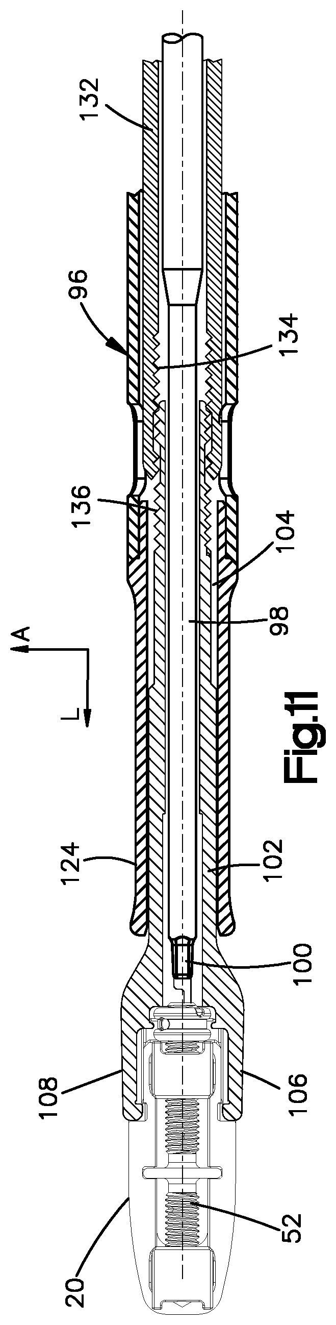
D00016

D00017

D00018
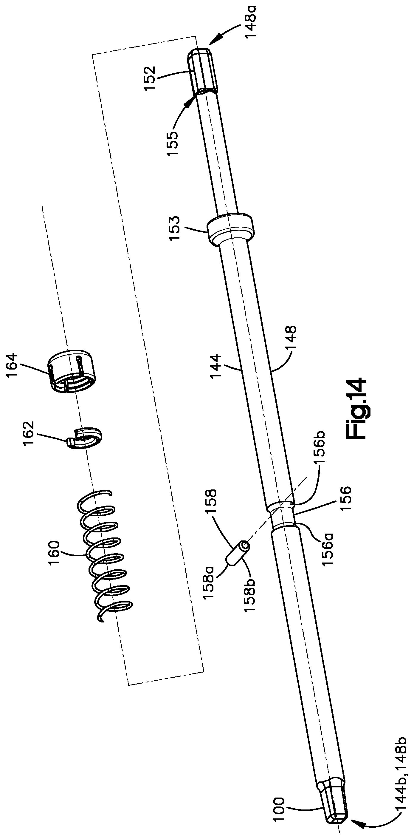
D00019

D00020

D00021

XML
uspto.report is an independent third-party trademark research tool that is not affiliated, endorsed, or sponsored by the United States Patent and Trademark Office (USPTO) or any other governmental organization. The information provided by uspto.report is based on publicly available data at the time of writing and is intended for informational purposes only.
While we strive to provide accurate and up-to-date information, we do not guarantee the accuracy, completeness, reliability, or suitability of the information displayed on this site. The use of this site is at your own risk. Any reliance you place on such information is therefore strictly at your own risk.
All official trademark data, including owner information, should be verified by visiting the official USPTO website at www.uspto.gov. This site is not intended to replace professional legal advice and should not be used as a substitute for consulting with a legal professional who is knowledgeable about trademark law.