Method and system for providing diversity in a network that utilizes distributed transceivers with array processing
Moshfeghi December 29, 2
U.S. patent number 10,880,055 [Application Number 16/129,413] was granted by the patent office on 2020-12-29 for method and system for providing diversity in a network that utilizes distributed transceivers with array processing. This patent grant is currently assigned to GOLBA LLC. The grantee listed for this patent is Golba LLC. Invention is credited to Mehran Moshfeghi.


| United States Patent | 10,880,055 |
| Moshfeghi | December 29, 2020 |
Method and system for providing diversity in a network that utilizes distributed transceivers with array processing
Abstract
A communication device that comprises a plurality of distributed transceivers, a central processor and a network management engine may be configured based on one or more diversity modes of operations. The diversity modes of operations may comprise a spatial diversity mode, a frequency diversity mode, and/or a polarization diversity mode. Diversity mode configuration may comprise forming, based on selected diversity mode, a plurality of communication modules from the plurality of distributed transceivers, wherein each of the plurality of communication modules may comprise one or more antennas and/or antenna array elements, and one or more of said plurality of distributed transceivers associated with said one or more antennas and/or antenna array elements. The plurality of communication modules may be utilized to concurrently communicate multiple data streams. The multiple data streams may comprise the same data.
| Inventors: | Moshfeghi; Mehran (Rancho Palos Verdes, CA) | ||||||||||
|---|---|---|---|---|---|---|---|---|---|---|---|
| Applicant: |
|
||||||||||
| Assignee: | GOLBA LLC (Rancho Palos Verdes,
CA) |
||||||||||
| Family ID: | 1000005271805 | ||||||||||
| Appl. No.: | 16/129,413 | ||||||||||
| Filed: | September 12, 2018 |
Prior Publication Data
| Document Identifier | Publication Date | |
|---|---|---|
| US 20190097770 A1 | Mar 28, 2019 | |
Related U.S. Patent Documents
| Application Number | Filing Date | Patent Number | Issue Date | ||
|---|---|---|---|---|---|
| 15706759 | Sep 17, 2017 | ||||
| 13473160 | Oct 3, 2017 | 9780928 | |||
| 61548201 | Oct 17, 2011 | ||||
| Current U.S. Class: | 1/1 |
| Current CPC Class: | H04W 72/0453 (20130101); H04B 7/043 (20130101); H04W 88/02 (20130101); H04W 88/06 (20130101); H04B 7/0689 (20130101); H04W 72/0473 (20130101); H04B 7/0897 (20130101); H04B 7/0413 (20130101); H04L 27/12 (20130101); H04W 4/80 (20180201); H04W 24/08 (20130101); H04W 72/046 (20130101); H04B 1/40 (20130101); H04L 5/0032 (20130101); H04B 7/024 (20130101); H04W 72/085 (20130101); H04B 7/0408 (20130101); H04W 84/12 (20130101); Y02D 30/70 (20200801) |
| Current International Class: | H04L 5/00 (20060101); H04B 7/0413 (20170101); H04B 7/08 (20060101); H04W 24/08 (20090101); H04W 72/04 (20090101); H04B 7/024 (20170101); H04B 7/0408 (20170101); H04B 7/0426 (20170101); H04B 1/40 (20150101); H04L 27/12 (20060101); H04W 4/80 (20180101); H04W 88/06 (20090101); H04B 7/06 (20060101); H04W 88/02 (20090101); H04W 72/08 (20090101); H04W 84/12 (20090101) |
| Field of Search: | ;455/509 |
References Cited [Referenced By]
U.S. Patent Documents
| 3618097 | November 1971 | Mcleod, Jr. |
| 3835469 | September 1974 | Chen et al. |
| 5473602 | December 1995 | McKenna et al. |
| 5479651 | December 1995 | Nakaguchi |
| 5525990 | June 1996 | Lewis |
| 5561850 | October 1996 | Makitalo et al. |
| 5598173 | January 1997 | Forti et al. |
| 5666124 | September 1997 | Chethik et al. |
| 5771017 | June 1998 | Dean et al. |
| 5883602 | March 1999 | Volman |
| 5905473 | May 1999 | Taenzer |
| 5936577 | August 1999 | Shoki et al. |
| 5940033 | August 1999 | Locher et al. |
| 6018316 | January 2000 | Rudish et al. |
| 6307502 | October 2001 | Marti-Canales et al. |
| 6405018 | June 2002 | Reudink et al. |
| 6433920 | August 2002 | Welch et al. |
| 6456252 | September 2002 | Goyette |
| 6487417 | November 2002 | Rossoni et al. |
| 6577631 | June 2003 | Keenan et al. |
| 6600776 | July 2003 | Alamouti et al. |
| 6718159 | April 2004 | Sato |
| 6802035 | October 2004 | Catreux et al. |
| 6804491 | October 2004 | Uesugi |
| 6992622 | January 2006 | Chiang et al. |
| 7020482 | March 2006 | Medvedev et al. |
| 7058367 | June 2006 | Luo et al. |
| 7187949 | March 2007 | Chang et al. |
| 7206294 | April 2007 | Garahi et al. |
| 7248217 | July 2007 | Mani et al. |
| 7248841 | July 2007 | Agee et al. |
| 7260141 | August 2007 | Bierly et al. |
| 7333455 | February 2008 | Bolt et al. |
| 7339979 | March 2008 | Kelkar |
| 7363058 | April 2008 | Gustaf |
| 7424225 | September 2008 | Elliott |
| 7574236 | August 2009 | Mansour |
| 7636573 | December 2009 | Walton et al. |
| 7688909 | March 2010 | Tsutsui |
| 7689216 | March 2010 | Wandel |
| 7710319 | May 2010 | Nassiri-Toussi et al. |
| 7890114 | February 2011 | Braun et al. |
| 7904117 | March 2011 | Doan et al. |
| 7911985 | March 2011 | Proctor, Jr. et al. |
| 7920889 | April 2011 | Hoshino et al. |
| 7986742 | July 2011 | Ketchum et al. |
| 8014366 | September 2011 | Wax et al. |
| 8098752 | January 2012 | Hwang et al. |
| 8121235 | February 2012 | Sun et al. |
| 8126408 | February 2012 | Ahrony et al. |
| 8140122 | March 2012 | Park et al. |
| 8160601 | April 2012 | Veselinovic et al. |
| 8175184 | May 2012 | Kim et al. |
| 8190102 | May 2012 | Rofougaran |
| 8203978 | June 2012 | Rodney et al. |
| 8228188 | July 2012 | Key et al. |
| 8279132 | October 2012 | Jung et al. |
| 8280445 | October 2012 | Yong et al. |
| 8314736 | November 2012 | Moshfeghi |
| 8320304 | November 2012 | Deb et al. |
| 8364188 | January 2013 | Deb et al. |
| 8369791 | February 2013 | Hafeez |
| 8385305 | February 2013 | Negus et al. |
| 8385452 | February 2013 | Gorokhov |
| 8396157 | March 2013 | Li et al. |
| 8457798 | June 2013 | Hackett |
| 8462047 | June 2013 | Ai et al. |
| 8482462 | July 2013 | Komijani et al. |
| 8570988 | October 2013 | Wallace et al. |
| 8588193 | November 2013 | Ho et al. |
| 8620301 | December 2013 | Hessel |
| 8644262 | February 2014 | Sun et al. |
| 8654815 | February 2014 | Forenza et al. |
| 8744513 | June 2014 | Chen et al. |
| 8750264 | June 2014 | Shatti |
| 8780943 | July 2014 | Moshfeghi |
| 8787469 | July 2014 | Kim et al. |
| 8817678 | August 2014 | Moshfeghi |
| 8854255 | October 2014 | Ehret |
| 8885628 | November 2014 | Palanki et al. |
| 9037094 | May 2015 | Moshfeghi |
| 9065515 | June 2015 | Pezennec et al. |
| 9112648 | August 2015 | Moshfeghi |
| 9185601 | November 2015 | Frerking et al. |
| 9197982 | November 2015 | Moshfeghi |
| 9225482 | December 2015 | Moshfeghi |
| 9226092 | December 2015 | Moshfeghi |
| 9252908 | February 2016 | Branlund |
| 9253587 | February 2016 | Moshfeghi |
| 9438389 | September 2016 | Moshfeghi et al. |
| 9456354 | September 2016 | Branlund |
| 9548805 | January 2017 | Moshfeghi et al. |
| 9602257 | March 2017 | Moshfeghi et al. |
| 9660777 | May 2017 | Moshfeghi et al. |
| 9680554 | June 2017 | Moshfeghi et al. |
| 9686060 | June 2017 | Moshfeghi |
| 9698948 | July 2017 | Moshfeghi |
| 9736637 | August 2017 | Larsen et al. |
| 9780928 | October 2017 | Moshfeghi et al. |
| 9787103 | October 2017 | Leabman et al. |
| 9829563 | November 2017 | Xiao et al. |
| 9923620 | March 2018 | Moshfeghi et al. |
| 10020861 | July 2018 | Moshfeghi et al. |
| 10069555 | September 2018 | Islam et al. |
| 10069608 | September 2018 | Moshfeghi et al. |
| 10084576 | September 2018 | Moshfeghi et al. |
| 10090887 | October 2018 | Rofougaran et al. |
| 10103853 | October 2018 | Moshfeghi |
| 10199717 | February 2019 | Rofougaran et al. |
| 10277370 | April 2019 | Moshfeghi |
| 10320090 | June 2019 | Zou et al. |
| 10348371 | July 2019 | Rofougaran et al. |
| 10560179 | February 2020 | Gharavi et al. |
| 10587313 | March 2020 | Yoon et al. |
| 10666326 | May 2020 | Rofougaran et al. |
| 2002/0034958 | March 2002 | Oberschmidt et al. |
| 2002/0132600 | September 2002 | Rudrapatna |
| 2002/0193074 | December 2002 | Squibbs |
| 2002/0196186 | December 2002 | Holt |
| 2003/0012208 | January 2003 | Bernheim et al. |
| 2003/0090418 | May 2003 | Howell |
| 2003/0125040 | July 2003 | Walton et al. |
| 2003/0129989 | July 2003 | Gholmieh et al. |
| 2003/0236109 | December 2003 | Nagata |
| 2004/0077354 | April 2004 | Jason et al. |
| 2004/0077379 | April 2004 | Smith et al. |
| 2004/0082356 | April 2004 | Walton et al. |
| 2004/0095907 | May 2004 | Agee et al. |
| 2004/0110469 | June 2004 | Judd et al. |
| 2004/0116129 | June 2004 | Wilson |
| 2004/0127174 | July 2004 | Frank et al. |
| 2004/0166808 | August 2004 | Hasegawa et al. |
| 2004/0204114 | October 2004 | Brennan et al. |
| 2005/0048964 | March 2005 | Cohen et al. |
| 2005/0069252 | March 2005 | Hwang et al. |
| 2005/0088358 | April 2005 | Larry et al. |
| 2005/0134517 | June 2005 | Gottl |
| 2005/0136943 | June 2005 | Banerjee et al. |
| 2005/0181755 | August 2005 | Hoshino et al. |
| 2005/0232216 | October 2005 | Webster et al. |
| 2005/0237971 | October 2005 | Skraparlis |
| 2005/0243756 | November 2005 | Cleveland et al. |
| 2005/0270227 | December 2005 | Stephens |
| 2006/0025178 | February 2006 | Tao et al. |
| 2006/0063494 | March 2006 | Zhang et al. |
| 2006/0121946 | June 2006 | Walton et al. |
| 2006/0246922 | November 2006 | Gasbarro et al. |
| 2006/0267839 | November 2006 | Vaskelainen et al. |
| 2007/0001924 | January 2007 | Hirabayashi |
| 2007/0040025 | February 2007 | Goel et al. |
| 2007/0052519 | March 2007 | Talty et al. |
| 2007/0066254 | March 2007 | Tsuchie et al. |
| 2007/0093270 | April 2007 | Lagnado |
| 2007/0100548 | May 2007 | Small |
| 2007/0115800 | May 2007 | Fonseka et al. |
| 2007/0116012 | May 2007 | Chang |
| 2007/0160014 | July 2007 | Larsson |
| 2007/0280310 | December 2007 | Muenter et al. |
| 2008/0025208 | January 2008 | Chan |
| 2008/0026763 | January 2008 | Rensburg et al. |
| 2008/0076370 | March 2008 | Kotecha et al. |
| 2008/0117961 | May 2008 | Han et al. |
| 2008/0166975 | July 2008 | Kim et al. |
| 2008/0167049 | July 2008 | Karr et al. |
| 2008/0212582 | September 2008 | Zwart et al. |
| 2008/0225758 | September 2008 | Proctor et al. |
| 2008/0258993 | October 2008 | Gummalla et al. |
| 2008/0261509 | October 2008 | Sen |
| 2008/0303701 | December 2008 | Zhang et al. |
| 2008/0305820 | December 2008 | Sadiq et al. |
| 2008/0309555 | December 2008 | Fan et al. |
| 2008/0315944 | December 2008 | Brown |
| 2009/0009392 | January 2009 | Jacomb-Hood et al. |
| 2009/0010215 | January 2009 | Kim et al. |
| 2009/0028120 | January 2009 | Lee |
| 2009/0029645 | January 2009 | Leroudier |
| 2009/0093265 | April 2009 | Kimura et al. |
| 2009/0156227 | June 2009 | Frerking et al. |
| 2009/0161235 | June 2009 | Border et al. |
| 2009/0175214 | July 2009 | Sfar et al. |
| 2009/0195455 | August 2009 | Kim et al. |
| 2009/0224137 | September 2009 | Hoermann |
| 2009/0233545 | September 2009 | Sutskover et al. |
| 2009/0296846 | December 2009 | Maru |
| 2009/0325479 | December 2009 | Chakrabarti et al. |
| 2010/0042881 | February 2010 | Wong |
| 2010/0046655 | February 2010 | Lee et al. |
| 2010/0080197 | April 2010 | Kanellakis et al. |
| 2010/0090898 | April 2010 | Gallagher et al. |
| 2010/0105403 | April 2010 | Lennartson et al. |
| 2010/0117890 | May 2010 | Vook et al. |
| 2010/0124895 | May 2010 | Martin et al. |
| 2010/0136922 | June 2010 | Rofougaran |
| 2010/0149039 | June 2010 | Komijani et al. |
| 2010/0167639 | July 2010 | Ranson et al. |
| 2010/0172309 | July 2010 | Forenza et al. |
| 2010/0208776 | August 2010 | Song et al. |
| 2010/0220012 | September 2010 | Reede |
| 2010/0266061 | October 2010 | Cheng et al. |
| 2010/0267415 | October 2010 | Kakitsu |
| 2010/0273504 | October 2010 | Bull et al. |
| 2010/0284446 | November 2010 | Mu et al. |
| 2010/0291918 | November 2010 | Suzuki et al. |
| 2010/0304680 | December 2010 | Kuffner et al. |
| 2010/0304770 | December 2010 | Wietfeldt |
| 2010/0328157 | December 2010 | Culkin et al. |
| 2011/0002410 | January 2011 | Forenza et al. |
| 2011/0003610 | January 2011 | Key et al. |
| 2011/0045764 | February 2011 | Maruyama et al. |
| 2011/0063181 | March 2011 | Walker |
| 2011/0069773 | March 2011 | Doron et al. |
| 2011/0081875 | April 2011 | Imamura et al. |
| 2011/0105032 | May 2011 | Maruhashi et al. |
| 2011/0105167 | May 2011 | Pan et al. |
| 2011/0136478 | June 2011 | Trigui |
| 2011/0140954 | June 2011 | Fortuny-Guasch |
| 2011/0142104 | June 2011 | Coldrey et al. |
| 2011/0149835 | June 2011 | Shimada et al. |
| 2011/0164510 | July 2011 | Zheng et al. |
| 2011/0190005 | August 2011 | Cheon et al. |
| 2011/0194504 | August 2011 | Gorokhov et al. |
| 2011/0212684 | September 2011 | Nam et al. |
| 2011/0222616 | September 2011 | Jiang et al. |
| 2011/0268037 | November 2011 | Fujimoto |
| 2011/0299441 | December 2011 | Petrovic et al. |
| 2012/0002742 | January 2012 | Cheng |
| 2012/0015603 | January 2012 | Proctor et al. |
| 2012/0034924 | February 2012 | Kalhan |
| 2012/0057508 | March 2012 | Moshfeghi |
| 2012/0082070 | April 2012 | Hart et al. |
| 2012/0082072 | April 2012 | Shen |
| 2012/0083207 | April 2012 | Rofougaran et al. |
| 2012/0083223 | April 2012 | Li et al. |
| 2012/0083225 | April 2012 | Rofougaran et al. |
| 2012/0083233 | April 2012 | Rofougaran et al. |
| 2012/0083306 | April 2012 | Rofougaran et al. |
| 2012/0093209 | April 2012 | Schmidt et al. |
| 2012/0120884 | May 2012 | Yu et al. |
| 2012/0129543 | May 2012 | Patel et al. |
| 2012/0131650 | May 2012 | Gutt et al. |
| 2012/0149300 | June 2012 | Forster |
| 2012/0184203 | July 2012 | Tulino et al. |
| 2012/0184219 | July 2012 | Richardson et al. |
| 2012/0194385 | August 2012 | Schmidt et al. |
| 2012/0206299 | August 2012 | Valdes-Garcia |
| 2012/0230274 | September 2012 | Xiao et al. |
| 2012/0238202 | September 2012 | Kim et al. |
| 2012/0250659 | October 2012 | Sambhwani |
| 2012/0257516 | October 2012 | Pazhyannur et al. |
| 2012/0259547 | October 2012 | Morlock et al. |
| 2012/0314570 | December 2012 | Forenza et al. |
| 2013/0027240 | January 2013 | Chowdhury |
| 2013/0027250 | January 2013 | Chen |
| 2013/0039342 | February 2013 | Kazmi |
| 2013/0040558 | February 2013 | Kazmi |
| 2013/0044028 | February 2013 | Lea et al. |
| 2013/0057447 | March 2013 | Pivit et al. |
| 2013/0089123 | April 2013 | Rahul et al. |
| 2013/0094439 | April 2013 | Moshfeghi |
| 2013/0094440 | April 2013 | Moshfeghi |
| 2013/0094522 | April 2013 | Moshfeghi |
| 2013/0094544 | April 2013 | Moshfeghi |
| 2013/0095747 | April 2013 | Moshfeghi |
| 2013/0095770 | April 2013 | Moshfeghi |
| 2013/0095874 | April 2013 | Moshfeghi et al. |
| 2013/0114468 | May 2013 | Hui et al. |
| 2013/0155891 | June 2013 | Dinan |
| 2013/0272220 | October 2013 | Li et al. |
| 2013/0272437 | October 2013 | Eidson et al. |
| 2013/0286962 | October 2013 | Heath, Jr. et al. |
| 2013/0287139 | October 2013 | Zhu et al. |
| 2013/0322561 | December 2013 | Abreu et al. |
| 2013/0324055 | December 2013 | Kludt et al. |
| 2013/0343235 | December 2013 | Khan |
| 2014/0003338 | January 2014 | Rahul et al. |
| 2014/0010319 | January 2014 | Baik et al. |
| 2014/0016573 | January 2014 | Nuggehalli et al. |
| 2014/0035731 | February 2014 | Chan et al. |
| 2014/0044041 | February 2014 | Moshfeghi |
| 2014/0044042 | February 2014 | Moshfeghi |
| 2014/0044043 | February 2014 | Moshfeghi et al. |
| 2014/0045478 | February 2014 | Moshfeghi |
| 2014/0045541 | February 2014 | Moshfeghi et al. |
| 2014/0072078 | March 2014 | Sergeyev et al. |
| 2014/0079165 | March 2014 | Kludt et al. |
| 2014/0086191 | March 2014 | Berntsen et al. |
| 2014/0104124 | April 2014 | Chernokalov et al. |
| 2014/0125539 | May 2014 | Katipally et al. |
| 2014/0133435 | May 2014 | Forenza et al. |
| 2014/0161018 | June 2014 | Chang et al. |
| 2014/0198696 | July 2014 | Li et al. |
| 2014/0241296 | August 2014 | Shattil |
| 2014/0266866 | September 2014 | Swirhun et al. |
| 2015/0003307 | January 2015 | Moshfeghi et al. |
| 2015/0011160 | January 2015 | Jurgovan et al. |
| 2015/0031407 | January 2015 | Moshfeghi |
| 2015/0042744 | February 2015 | Ralston et al. |
| 2015/0091706 | April 2015 | Chemishkian et al. |
| 2015/0123496 | May 2015 | Leabman et al. |
| 2015/0229133 | August 2015 | Reynolds et al. |
| 2015/0241020 | August 2015 | Lee et al. |
| 2015/0296344 | October 2015 | Trojer et al. |
| 2015/0303950 | October 2015 | Shattil |
| 2015/0318897 | November 2015 | Hyde et al. |
| 2015/0318905 | November 2015 | Moshfeghi et al. |
| 2015/0341098 | November 2015 | Angeletti et al. |
| 2016/0014613 | January 2016 | Ponnampalam et al. |
| 2016/0043838 | February 2016 | Moshfeghi et al. |
| 2016/0054440 | February 2016 | Younis |
| 2016/0094092 | March 2016 | Davlantes et al. |
| 2016/0094318 | March 2016 | Shattil |
| 2016/0142114 | May 2016 | Moshfeghi et al. |
| 2016/0192400 | June 2016 | Sohn et al. |
| 2016/0197665 | July 2016 | Moshfeghi et al. |
| 2016/0203347 | July 2016 | Bartholomew et al. |
| 2016/0211905 | July 2016 | Moshfeghi et al. |
| 2016/0219567 | July 2016 | Gil et al. |
| 2016/0285481 | September 2016 | Cohen |
| 2017/0026218 | January 2017 | Shattil |
| 2017/0062944 | March 2017 | Zimmerman et al. |
| 2017/0078897 | March 2017 | Duan et al. |
| 2017/0126374 | May 2017 | Moshfeghi et al. |
| 2017/0156069 | June 2017 | Moshfeghi et al. |
| 2017/0201437 | July 2017 | Balakrishnan et al. |
| 2017/0212208 | July 2017 | Baek et al. |
| 2017/0230099 | August 2017 | Moshfeghi et al. |
| 2017/0237290 | August 2017 | Bakker et al. |
| 2017/0257155 | September 2017 | Liang et al. |
| 2017/0264014 | September 2017 | Le-Ngoc |
| 2017/0279573 | September 2017 | Moshfeghi et al. |
| 2017/0288727 | October 2017 | Rappaport |
| 2017/0317734 | November 2017 | Moshfeghi |
| 2017/0317801 | November 2017 | Moshfeghi et al. |
| 2017/0324480 | November 2017 | Elmirghani et al. |
| 2017/0332249 | November 2017 | Guey et al. |
| 2017/0338921 | November 2017 | Moshfeghi |
| 2017/0339625 | November 2017 | Stapleton |
| 2017/0353338 | December 2017 | Amadjikpe et al. |
| 2018/0026586 | January 2018 | Carbone et al. |
| 2018/0041270 | February 2018 | Buer et al. |
| 2018/0048390 | February 2018 | Palmer et al. |
| 2018/0090992 | March 2018 | Shrivastava et al. |
| 2018/0091270 | March 2018 | Moshfeghi |
| 2018/0109303 | April 2018 | Yoo et al. |
| 2018/0115305 | April 2018 | Islam et al. |
| 2018/0176799 | June 2018 | Lange et al. |
| 2018/0183152 | June 2018 | Turpin et al. |
| 2018/0220416 | August 2018 | Islam et al. |
| 2018/0234158 | August 2018 | Moshfeghi |
| 2019/0089434 | March 2019 | Rainish et al. |
| 2019/0123866 | April 2019 | Moshfeghi |
| 2019/0230626 | July 2019 | Rune et al. |
| 2019/0319754 | October 2019 | Moshfeghi |
| 2019/0319755 | October 2019 | Moshfeghi |
| 2019/0319756 | October 2019 | Moshfeghi |
| 2020/0076491 | March 2020 | Zhang et al. |
| 2020/0145079 | May 2020 | Marinier et al. |
| 1890441 | Feb 2008 | EP | |||
| 1890441 | Mar 2013 | EP | |||
| 2008027531 | Mar 2008 | WO | |||
| 2012055468 | May 2012 | WO | |||
| 2013058998 | Apr 2013 | WO | |||
| 2013058999 | Apr 2013 | WO | |||
| 2016115545 | Jul 2016 | WO | |||
Other References
|
Patent Board Decision--Examiner Affirmed for U.S. Appl. No. 13/473,144 dated Jun. 4, 2018. cited by applicant . Patent Board Decision--Examiner Affirmed in Part for U.S. Appl. No. 13/473,160 dated Feb. 21, 2017. cited by applicant . Patent Board Decision--Examiner Reversed for U.S. Appl. No. 13/919,932 dated Dec. 19, 2017. cited by applicant . Response to Rule 312 Communication for U.S. Appl. No. 15/834,894 dated Apr. 19, 2019; Miscellaneous Communication to Applicant for U.S. Appl. No. 15/834,894 dated Apr. 19, 2019. cited by applicant . Restriction Requirement for U.S. Appl. No. 15/893,626 dated Aug. 12, 2016. cited by applicant . Shimin Gong et al., "Backscatter Relay Communications Powered by Wireless Energy Beamforming," IEEE Trans. on Communication, 2018. cited by applicant . USPTO Miscellaneous communication for U.S. Appl. No. 15/834,894 dated Apr. 19, 2019. cited by applicant . Zeng et al., "Joint relay selection and beamforming for mmWave fronthauling network," 2017 IEEE/CIC International Conference on Communications in China, Oct. 22, 2017, 6 pages. cited by applicant . Corrected Notice of Allowance for U.S. Appl. No. 16/031,007 dated Sep. 16, 2019. cited by applicant . Corrected Notice of Allowance for U.S. Appl. No. 15/616,911 dated Oct. 31, 2019. cited by applicant . Corrected Notice of Allowance for U.S. Appl. No. 16/031,007 dated Oct. 22, 2019. cited by applicant . Corrected Notice of Allowance for U.S. Appl. No. 16/032,617 dated Oct. 28, 2019. cited by applicant . Corrected Notice of Allowance for U.S. Appl. No. 16/129,423 dated Nov. 7, 2019. cited by applicant . Misc Communication from USPTO for U.S. Appl. No. 16/382,386 dated Oct. 8, 2019. cited by applicant . Non-Final Office Action for U.S. Appl. No. 16/231,903 dated Sep. 18, 2019. cited by applicant . Non-Final Office Action for U.S. Appl. No. 16/294,025 dated Sep. 12, 2019. cited by applicant . Non-Final Office Action for U.S. Appl. No. 16/377,980 dated Aug. 21, 2019. cited by applicant . Non-Final Office Action for U.S. Appl. No. 16/526,544 dated Sep. 18, 2019. cited by applicant . Non-Final Office Action in U.S. Appl. No. 15/836,198 dated Oct. 31, 2019. cited by applicant . Notice of Allowance for U.S. Appl. No. 16/032,668 dated Sep. 20, 2019. cited by applicant . Notice of Allowance for U.S. Appl. No. 15/595,919 dated Oct. 25, 2019. cited by applicant . Notice of Allowance for U.S. Appl. No. 15/904,521 dated Sep. 20, 2019. cited by applicant . Notice of Allowance for U.S. Appl. No. 16/111,326 dated Oct. 10, 2019. cited by applicant . Non-Final Office Action for U.S. Appl. No. 16/016,619 dated Sep. 25, 2018. cited by applicant . Baggett, Benjamin M.W. Optimization of Aperiodically Spaced Phased Arrays for Wideband Applications. MS Thesis. Virginia Polytechnic Institute and State University, 2011. pp. 1-137. cited by applicant . Corrected Notice of Allowability for U.S. Appl. No. 15/904,521 dated May 6, 2019. cited by applicant . Corrected Notice of Allowance for U.S. Appl. No. 16/031,007 dated Jul. 8, 2019. cited by applicant . Corrected Notice of Allowance for U.S. Appl. No. 15/607,743 dated May 10, 2019. cited by applicant . Corrected Notice of Allowance for U.S. Appl. No. 15/904,521 dated Jun. 21, 2019. cited by applicant . Corrected Notice of Allowance for U.S. Appl. No. 15/904,521 dated May 10, 2019. cited by applicant . Corrected Notice of Allowance for U.S. Appl. No. 13/473,180 dated Jun. 11, 2014. cited by applicant . Corrected Notice of Allowance for U.S. Appl. No. 15/904,521. cited by applicant . Corrected Notice of Allowance for U.S. Appl. No. 16/031,007 dated Aug. 5, 2019. cited by applicant . Corrected Notice of Allowance in U.S. Appl. No. 15/607,743 dated Apr. 3, 2019. cited by applicant . Corrected Notice of Allowance in U.S. Appl. No. 15/835,971 dated Jul. 23, 2018. cited by applicant . Dennis R Morgan et al., "A same-frequency cellular repeater using adaptive feedback cancellation," Global Communications Conference (GLOBECOM), 2012 IEEE, IEEE, (2012) XP032375270, pp. 3825-3830, 2012. cited by applicant . Ex Parte Quayle Action for U.S. Appl. No. 16/032,668 dated Jul. 10, 2019. cited by applicant . Examiner's Answer to Appeal Brief for U.S. Appl. No. 13/473,144 dated Jul. 26, 2017. cited by applicant . Examiner's Answer to Appeal Brief for U.S. Appl. No. 13/473,160 dated Dec. 24, 2015. cited by applicant . Examiner's Answer to Appeal Brief for U.S. Appl. No. 13/919,932 dated Jan. 10, 2017. cited by applicant . Final Office Action for U.S. Appl. No. 13/473,144 dated Jul. 28, 2016. cited by applicant . Final Office Action for U.S. Appl. No. 13/473/144 dated Aug. 14, 2014. cited by applicant . Final Office Action for U.S. Appl. No. 13/919,932 dated Oct. 23, 2015. cited by applicant . Final Office Action for U.S. Appl. No. 13/919,972 dated Jan. 21, 2016. cited by applicant . Final Office Action for U.S. Appl. No. 14/940,130 dated Oct. 14, 2016. cited by applicant . Final Office Action for U.S. Appl. No. dated Oct. 22, 2014. cited by applicant . International Preliminary Report on Patentability for International Patent PCT/US2012/058839, 5 pages, dated Apr. 22, 2014. cited by applicant . International Preliminary Report on Patentability for International Patent PCT/US2012/058839, dated Apr. 22, 2014. cited by applicant . International Preliminary Report on Patentability for International Patent PCT/US2012/058842, 5 pages, dated Apr. 22, 2014. cited by applicant . International Search Report and the Written Opinion of the International Searching Authority in International application No. PCT/US12/58842, 6 pages, dated Jan. 4, 2013. cited by applicant . International Search Report and the Written Opinion of the International Searching Authority in International application No. PCT/US12/58839, 6 pages, dated Apr. 4, 2013. cited by applicant . International Search Report in PCT/US2018/064184 dated Jul. 1, 2019. cited by applicant . Invitation to Pay Additional Fees and, Where Applicable, Protest Fee, with Partial Search Report for PCT Appl No. PCT/US2018/064184 dated Apr. 10, 2019. cited by applicant . K. Flan and K. Huang, "Wirelessly Powered Backscatter Communication networks: Modeling, Coverage and Capacity," Apr. 9, 2016, Arxiv.com. cited by applicant . List of References and considered by Applicant for U.S. Appl. No. 14/325,218 dated Apr. 21, 2017. cited by applicant . Non-Final Office Action for U.S. Appl. No. 13/473,083 dated Mar. 3, 2014. cited by applicant . Non-Final Office Action for U.S. Appl. No. 13/473,096 dated Apr. 23, 2014. cited by applicant . Non-Final Office Action for U.S. Appl. No. 13/473,096 dated Dec. 9, 2013. cited by applicant . Non-Final Office Action for U.S. Appl. No. 13/473,096 dated Nov. 3, 2014. cited by applicant . Non-Final Office Action for U.S. Appl. No. 13/473,105 dated Nov. 25, 2013. cited by applicant . Non-Final Office Action for U.S. Appl. No. 13/473,113 dated Oct. 2, 2014. cited by applicant . Non-Final Office Action for U.S. Appl. No. 13/473,144 dated Feb. 6, 2014. cited by applicant . Non-Final Office Action for U.S. Appl. No. 13/473,144 dated Feb. 9, 2015. cited by applicant . Non-Final Office Action for U.S. Appl. No. 13/473,144 dated Oct. 7, 2015. cited by applicant . Non-Final Office Action for U.S. Appl. No. 13/473,160 dated Jan. 15, 2014. cited by applicant . Non-Final Office Action for U.S. Appl. No. 13/473,180 dated Sep. 12, 2013. cited by applicant . Non-Final Office Action for U.S. Appl. No. 13/919,922 dated Jan. 30, 2015. cited by applicant . Non-Final Office Action for U.S. Appl. No. 13/919,932 dated Feb. 6, 2015. cited by applicant . Non-Final Office Action for U.S. Appl. No. 13/919,958 dated Jan. 5, 2015. cited by applicant . Non-Final Office Action for U.S. Appl. No. 13/919,967 dated Feb. 9, 2015. cited by applicant . Non-Final Office Action for U.S. Appl. No. 13/919,972 dated Jun. 4, 2015. cited by applicant . Non-Final Office Action for U.S. Appl. No. 14/455,859 dated Nov. 13, 2015. cited by applicant . Non-Final Office Action for U.S. Appl. No. 14/709,136 dated Sep. 28, 2016. cited by applicant . Non-Final Office Action for U.S. Appl. No. 14/813,058 dated Jun. 10, 2016. cited by applicant . Non-Final Office Action for U.S. Appl. No. 14/940,130 dated Apr. 6, 2016. cited by applicant . Non-Final Office Action for U.S. Appl. No. 14/980,281 dated Apr. 20, 2016. cited by applicant . Non-Final Office Action for U.S. Appl. No. 14/980,338 dated Mar. 14, 2017. cited by applicant . Non-Final Office Action for U.S. Appl. No. 15/229,135 dated Dec. 21, 2017. cited by applicant . Non-Final Office Action for U.S. Appl. No. 15/372,417 dated May 3, 2018. cited by applicant . Non-Final Office Action for U.S. Appl. No. 15/441,209 dated Jul. 3, 2018. cited by applicant . Non-Final Office Action for U.S. Appl. No. 15/595,940 dated Nov. 17, 2017. cited by applicant . Non-Final Office Action for U.S. Appl. No. 15/616,911 dated Jan. 3, 2019. cited by applicant . Non-Final Office Action for U.S. Appl. No. 15/706,759 dated Jun. 12, 2018. cited by applicant . Non-Final Office Action for U.S. Appl. No. 15/893,626 dated Jun. 12, 2018. cited by applicant . Non-Final Office Action for U.S. Appl. No. 16/101,044 dated Dec. 26, 2018. cited by applicant . Non-Final Office Action for U.S. Appl. No. 16/125,757 dated Aug. 9, 2019. cited by applicant . Non-Final Office Action for U.S. Appl. No. 16/129,423 dated Feb. 4, 2019. cited by applicant . Non-Final Office Action in U.S. Appl. No. 15/432,091 dated Nov. 22, 2017. cited by applicant . Non-Final Office Action in U.S. Appl. No. 16/111,326 dated Mar. 1, 2019. cited by applicant . Notice of Allowance for U.S. Appl. No. 13/473,083 dated Jan. 7, 2015. cited by applicant . Notice of Allowance for U.S. Appl. No. 13/473,096 dated Apr. 17, 2015. cited by applicant . Notice of Allowance for U.S. Appl. No. 13/473,105 dated Jun. 10, 2014. cited by applicant . Notice of Allowance for U.S. Appl. No. 13/473,113 dated Aug. 10, 2015. cited by applicant . Notice of Allowance for U.S. Appl. No. 13/473,160 dated May 25, 2017. cited by applicant . Notice of Allowance for U.S. Appl. No. 13/473,180 dated May 1, 2014. cited by applicant . Notice of Allowance for U.S. Appl. No. 13/919,922 dated Oct. 27, 2015. cited by applicant . Notice of Allowance for U.S. Appl. No. 13/919,932 dated Feb. 28, 2018. cited by applicant . Notice of Allowance for U.S. Appl. No. 13/919,958 dated Sep. 2, 2015. cited by applicant . Notice of Allowance for U.S. Appl. No. 13/919,967 dated Jul. 29, 2019. cited by applicant . Notice of Allowance for U.S. Appl. No. 13/919,972 dated Dec. 20, 2016. cited by applicant . Notice of Allowance for U.S. Appl. No. 14/325,218 dated Dec. 19, 2016. cited by applicant . Notice of Allowance for U.S. Appl. No. 14/455,859 dated Apr. 20, 2016. cited by applicant . Notice of Allowance for U.S. Appl. No. 14/709,136 dated Feb. 16, 2017. cited by applicant . Notice of Allowance for U.S. Appl. No. 14/813,058 dated Nov. 7, 2016. cited by applicant . Notice of Allowance for U.S. Appl. No. 14/940,130 dated Feb. 1, 2017. cited by applicant . Notice of Allowance for U.S. Appl. No. 14/980,281 dated Feb. 7, 2017. cited by applicant . Notice of Allowance for U.S. Appl. No. 14/980,338 dated Feb. 22, 2018. cited by applicant . Notice of Allowance for U.S. Appl. No. 15/229,135 dated May 22, 2018. cited by applicant . Notice of Allowance for U.S. Appl. No. 15/372,417 dated Dec. 7, 2018. cited by applicant . Notice of Allowance for U.S. Appl. No. 15/441,209 dated Dec. 28, 2018. cited by applicant . Notice of Allowance for U.S. Appl. No. 15/472,148 dated Dec. 10, 2018. cited by applicant . Notice of Allowance for U.S. Appl. No. 15/595,919 dated Jun. 5, 2019. cited by applicant . Notice of Allowance for U.S. Appl. No. 15/595,940 dated May 1, 2018. cited by applicant . Notice of Allowance for U.S. Appl. No. 15/616,911 dated Jul. 24, 2019. cited by applicant . Notice of Allowance for U.S. Appl. No. 16/129,423 dated Jul. 15, 2019. cited by applicant . Notice of Allowance for U.S. Appl. No. 16/382,386 dated Jul. 24, 2019. cited by applicant . Notice of Allowance for U.S. Appl. No. 16/031,007 dated May 2, 2019. cited by applicant . Notice of Allowance in U.S. Appl. No. 15/432,091 dated Apr. 11, 2018. cited by applicant . Notice of Allowance in U.S. Appl. No. 15/607,743 dated Jan. 22, 2019. cited by applicant . Notice of Allowance in U.S. Appl. No. 15/834,894 dated Feb. 20, 2019. cited by applicant . Notice of Allowance in U.S. Appl. No. 15/835,971 dated May 29, 2018. cited by applicant . Notice of Allowance in U.S. Appl. No. 15/904,521 dated Mar. 20, 2019. cited by applicant . Notice of Allowance issued in U.S. Appl. No. 16/129,423 dated Jul. 15, 2019. cited by applicant . Corrected Notice of Allowability for U.S. Appl. No. 16/111,326 dated Mar. 9, 2020. cited by applicant . Corrected Notice of Allowance for U.S. Appl. No. 16/526,544 dated May 13, 2020. cited by applicant . Corrected Notice of Allowance for U.S. Appl. No. 15/836,198 dated May 22, 2020. cited by applicant . Corrected Notice of Allowance for U.S. Appl. No. 15/904,521 dated Mar. 12, 2020. cited by applicant . Corrected Notice of Allowance for U.S. Appl. No. 16/032,668 dated Mar. 23, 2020. cited by applicant . Corrected Notice of Allowance for U.S. Appl. No. 16/111,326 dated Apr. 23, 2020. cited by applicant . Corrected Notice of Allowance for U.S. Appl. No. 16/294,025 dated May 18, 2020. cited by applicant . Final Office Action for U.S. Appl. No. 15/256,222 dated Oct. 4, 2019. cited by applicant . Final Office Action for U.S. Appl. No. 16/377,980 dated Mar. 4, 2020. cited by applicant . Final Office Action for U.S. Appl. No. 16/388,043 dated Apr. 15, 2020. cited by applicant . Non-Final Office Action for U.S. Appl. No. 15/256,222 dated Aug. 27, 2018. cited by applicant . Non-Final Office Action for U.S. Appl. No. 15/256,222 dated Mar. 21, 2019. cited by applicant . Non-Final Office Action for U.S. Appl. No. 16/125,757 dated Mar. 23, 2020. cited by applicant . Non-Final Office Action for U.S. Appl. No. 16/153,735 dated May 13, 2020. cited by applicant . Non-Final Office Action for U.S. Appl. No. 16/364,956 dated Apr. 10, 2020. cited by applicant . Non-Final Office Action for U.S. Appl. No. 16/377,847 dated Apr. 20, 2020. cited by applicant . Non-Final Office Action for U.S. Appl. No. 16/675,290 dated Apr. 30, 2020. cited by applicant . Notice of Allowance for U.S. Appl. No. 15/256,222 dated Apr. 3, 2020. cited by applicant . Notice of Allowance for U.S. Appl. No. 15/607,750 dated Jun. 1, 2020. cited by applicant . Notice of Allowance for U.S. Appl. No. 15/836,198 dated Apr. 17, 2020. cited by applicant . Notice of Allowance for U.S. Appl. No. 16/231,903 dated Mar. 24, 2020. cited by applicant . Notice of Allowance for U.S. Appl. No. 16/377,980 dated Apr. 14, 2020. cited by applicant . Notice of Allowance for U.S. Appl. No. 16/526,544 dated Apr. 9, 2020. cited by applicant . Supplemental Notice of Allowance for U.S. Appl. No. 16/129,423 dated Mar. 3, 2020. cited by applicant . Supplemental Notice of Allowance for U.S. Appl. No. 16/231,903 dated Apr. 30, 2020. cited by applicant . Supplemental Notice of Allowance for U.S. Appl. No. 16/294,025 dated Mar. 25, 2020. cited by applicant . Corrected Notice of Allowance for U.S. Appl. No. 16/382,386 dated Dec. 30, 2019. cited by applicant . Corrected Notice of Allowance for U.S. Appl. No. 15/616,911 dated Jan. 24, 2020. cited by applicant . Corrected Notice of Allowance for U.S. Appl. No. 15/616,911 dated Dec. 12, 2019. cited by applicant . Corrected Notice of Allowance for U.S. Appl. No. 15/904,521 dated Jan. 8, 2020. cited by applicant . Corrected Notice of Allowance for U.S. Appl. No. 16/032,617 dated Jan. 9, 2020. cited by applicant . Corrected Notice of Allowance for U.S. Appl. No. 16/032,668 dated Dec. 30, 2019. cited by applicant . Corrected Notice of Allowance for U.S. Appl. No. 16/129,423 dated Jan. 23, 2020. cited by applicant . Corrected Notice of Allowance for U.S. Appl. No. 16/382,386 dated Feb. 6, 2020. cited by applicant . Final Office Action for U.S. Appl. No. 16/125,757 dated Dec. 2, 2019. cited by applicant . Final Office Action for U.S. Appl. No. 16/526,544 dated Feb. 12, 2020. cited by applicant . Non-Final Office Action for U.S. Appl. No. 16/388,043 dated Dec. 27, 2019. cited by applicant . Non-Final Office Action for U.S. Appl. No. 16/666,680 dated Feb. 19, 2020. cited by applicant . Notice of Allowance for U.S. Appl. No. 16/129,423 dated Nov. 27, 2019. cited by applicant . Notice of Allowance for U.S. Appl. No. 16/294,025 dated Jan. 13, 2020. cited by applicant . Supplemental Notice of Allowance for U.S. Appl. No. 16/032,668 dated Feb. 14, 2020. cited by applicant . Corrected Notice of Allowability for U.S. Appl. No. 15/256,222 dated Jul. 10, 2020. cited by applicant . Corrected Notice of Allowability for U.S. Appl. No. 16/377,980 dated Jul. 22, 2020. cited by applicant . Corrected Notice of Allowability for U.S. Appl. No. 16/526,544 dated Jul. 16, 2020. cited by applicant . Corrected Notice of Allowance for U.S. Appl. No. 16/526,544 dated Aug. 25, 2020. cited by applicant . Final Office Action for U.S. Appl. No. 16/125,757 dated Jul. 15, 2020. cited by applicant . Final Office Action for U.S. Appl. No. 16/377,847 dated Jul. 13, 2020. cited by applicant . Final Office Action for U.S. Appl. No. 16/666,680 dated Jun. 29, 2020. cited by applicant . Non-Final Office Action for U.S. Appl. No. 16/204,397 dated Sep. 17, 2020. cited by applicant . Non-Final Office Action for U.S. Appl. No. 16/388,043 dated Aug. 3, 2020. cited by applicant . Non-Final Office Action for U.S. Appl. No. 16/451,998 dated Sep. 11, 2020. cited by applicant . Non-Final Office Action for U.S. Appl. No. 16/452,023 dated Sep. 9, 2020. cited by applicant . Non-Final Office Action for U.S. Appl. No. 16/819,388 dated Jul. 2, 2020. cited by applicant . Non-Final Office Action for U.S. Appl. No. 16/866,536 dated Sep. 1, 2020. cited by applicant . Notice of Allowance for U.S. Appl. No. 16/153,735 dated Jul. 2, 2020. cited by applicant . Notice of Allowance for U.S. Appl. No. 16/684,789 dated Jul. 10, 2020. cited by applicant . Supplemental Notice of Allowability for U.S. Appl. No. 16/153,735 dated Jul. 22, 2020. cited by applicant . Supplemental Notice of Allowance for U.S. Appl. No. 16/231,903 dated Jul. 1, 2020. cited by applicant . Corrected Notice of Allowance for U.S. Appl. No. 15/256,222 dated Oct. 28, 2020. cited by applicant . Corrected Notice of Allowance for U.S. Appl. No. 15/836,198 dated Oct. 2, 2020. cited by applicant . Corrected Notice of Allowance for U.S. Appl. No. 16/377,980 dated Oct. 5, 2020. cited by applicant . Corrected Notice of Allowance for U.S. Appl. No. 16/526,544 dated Sep. 25, 2020. cited by applicant . Final Office Action for U.S. Appl. No. 16/364,956 dated Oct. 2, 2020. cited by applicant . Non-Final Office Action for U.S. Appl. No. 16/233,044 dated Oct. 14, 2020. cited by applicant . Non-Final Office Action for U.S. Appl. No. 16/398,156 dated Oct. 15, 2020. cited by applicant . Non-Final Office Action for U.S. Appl. No. 16/461,980 dated Sep. 21, 2020. cited by applicant . Non-Final Office Action for U.S. Appl. No. 16/689,758 dated Sep. 29, 2020. cited by applicant . Notice of Allowance for U.S. Appl. No. 16/125,757 dated Oct. 28, 2020. cited by applicant . Notice of Allowance for U.S. Appl. No. 16/388,043 dated Nov. 5, 2020. cited by applicant . Notice of Allowance for U.S. Appl. No. 16/927,470 dated Oct. 29, 2020. cited by applicant . Supplemental Notice of Allowance for U.S. Appl. No. 16/153,735 dated Oct. 9, 2020. cited by applicant. |
Primary Examiner: Akinyemi; Ajibola A
Attorney, Agent or Firm: Chip Law Group
Parent Case Text
CLAIM OF PRIORITY
This patent application makes reference to, claims priority to and claims benefit from U.S. Provisional Application Ser. No. 61/548,201 filed on Oct. 17, 2011.
The above stated application is hereby incorporated herein by reference in its entirety.
CROSS-REFERENCE TO RELATED APPLICATIONS/INCORPORATION BY REFERENCE
This patent application is a continuation application of U.S. patent application Ser. No. 15/706,759, entitled "METHOD AND SYSTEM FOR PROVIDING DIVERSITY IN A NETWORK THAT UTILIZES DISTRIBUTED TRANSCEIVERS WITH ARRAY PROCESSING," filed Sep. 17, 2017, published as U.S. Patent Publication 2018/0091270. U.S. patent application Ser. No. 15/706,759 is a continuation application of U.S. patent application Ser. No. 13/473,160, entitled "METHOD AND SYSTEM FOR PROVIDING DIVERSITY IN A NETWORK THAT UTILIZES DISTRIBUTED TRANSCEIVERS WITH ARRAY PROCESSING," filed May 16, 2016, issued as U.S. Pat. No. 9,780,928. U.S. patent application Ser. No. 13/473,160 makes reference to, claims priority to and claims benefit from U.S. Provisional Application No. 61/548,201 filed on Oct. 17, 2011. The contents of U.S. patent application Ser. No. 15/706,759, published as U.S. Patent Publication 2018/0091270; U.S. patent application Ser. No. 13/473,160, issued as U.S. Pat. No. 9,780,928; and U.S. Provisional Application No. 61/548,201 are hereby incorporated by reference.
Each of the above stated applications is hereby incorporated herein by reference in its entirety.
Claims
What is claimed is:
1. A method, comprising: in a device that comprises a plurality of distributed transceivers, a central processor and a network management engine: switching from a first operating diversity mode of a plurality of operating modes to a second operating mode of said plurality of operating modes based on a change in location of at least one user device with respect to at least one distributed transceiver of said plurality of distributed transceivers, wherein said plurality of operating modes comprises selection of a subset of antennas of said at least one distributed transceiver and coordination of at least a certain aspect of operations established between said at least one user device with said subset of antennas of said at least one distributed transceiver; configuring a plurality of communication modules from one or more of said plurality of distributed transceivers, wherein: said configuration is based on said second operating mode; and each of said plurality of communication modules comprises one or more antennas or antenna array elements, and one or more of said plurality of distributed transceivers associated with said one or more antennas or antenna array elements; and concurrently communicating data streams via said plurality of communication modules.
2. The method according to claim 1, further comprising switching among said plurality of operating modes during said communication.
3. The method according to claim 2, further comprising reconfiguring one or more of said plurality of communication modules based on said switching.
4. The method according to claim 2, wherein said plurality of operating modes comprise a spatial diversity mode, a frequency diversity mode, and a polarization diversity mode.
5. The method according to claim 1, wherein each of said concurrently communicated data streams comprises the same data.
6. The method according to claim 1, further comprising monitoring, by said network management engine, communication related information associated with at least one of said configuration of said plurality of communication modules or said communication of said data streams.
7. The method according to claim 6, further comprising selecting a diversity mode of said plurality of operating modes based on said monitoring.
8. The method according to claim 1, further comprising configuring, based on location of one or more reflectors, at least one of beamforming settings or antenna arrangement for one or more of said plurality of communication modules.
9. The method according to claim 1, further comprising determining at least one of connection types or communication protocols that are utilized for establishing one or more links via said plurality of communication modules, wherein the connection types or communication protocols are determined to perform said communication of said data streams.
10. The method according to claim 1, further comprising allocating communication resources to said plurality of communication modules for use during said communication of said data streams, wherein at least one of said allocated communication resources are shared among said plurality of communication modules.
11. The method according to claim 1, further comprising switching from said first operating mode of said plurality of operating modes to said second operating mode of said plurality of operating modes based on at least one of number of users, number of streams needed, or available frequency channels.
12. A system, comprising: a device that comprises a plurality of distributed transceivers, a central processor and a network management engine, said device is operable to: switch from a first operating mode of a plurality of operating modes to a second operating mode of said plurality of operating modes based on a change in location of at least one user device with respect to at least one distributed transceiver of said plurality of distributed transceivers, wherein said plurality of operating modes comprises selection of a subset of antennas of said at least one distributed transceiver and coordination of at least a certain aspect of operations established between said at least one user device with said subset of antennas of said at least one distributed transceiver; configure a plurality of communication modules from one or more of said plurality of distributed transceivers, wherein: said configuration is based on said second operating mode; and each of said plurality of communication modules comprises one or more antennas or antenna array elements, and one or more of said plurality of distributed transceivers associated with said one or more antennas or antenna array elements; and concurrently communicate data streams via said configured plurality of communication modules.
13. The system according to claim 12, wherein said device is further operable to switch among said plurality of operating modes during said communication.
14. The system according to claim 13, wherein said central processor is operable to reconfigure one or more of said plurality of communication modules based on said switching.
15. The system according to claim 13, wherein said plurality of operating modes comprise a spatial diversity mode, a frequency diversity mode, and a polarization diversity mode.
16. The system according to claim 12, wherein each of said concurrently communicated data streams comprises the same data.
17. The system according to claim 12, wherein said network management engine is operable to monitor communication related information associated with at least one of said configuration of said plurality of communication modules or said communication of said data streams.
18. The system according to claim 17, wherein said device is further operable to select a diversity mode of said plurality of operating modes based on said monitoring.
19. The system according to claim 12, wherein said central processor is operable to configure, based on location of one or more reflectors, at least one of beamforming settings or antenna arrangement for one or more of said plurality of communication modules.
20. The system according to claim 12, wherein said central processor is operable to determine at least one of connection types or communication protocols that are utilized for establishing one or more links via said plurality of communication modules, wherein the connection types or communication protocols are determined to perform said communication of said data streams.
21. The system according to claim 20, wherein said device is further operable to allocate communication resources to said plurality of communication modules for use during said communication of said data streams, wherein at least one of said allocated communication resources are shared among said plurality of communication modules.
Description
FEDERALLY SPONSORED RESEARCH OR DEVELOPMENT
[Not Applicable].
MICROFICHE/COPYRIGHT REFERENCE
[Not Applicable].
FIELD OF THE INVENTION
Certain embodiments of the invention relate to communications. More specifically, certain embodiments of the invention relate to a method and a system for providing diversity in a network that utilizes distributed transceivers with array processing.
BACKGROUND OF THE INVENTION
Millimeter Wave (mmWave) devices are being utilized for high throughput wireless communications at very high carrier frequencies. There are several standards bodies such as 60 GHz wireless standard, WirelessHD, WiGig, and WiFi IEEE 802.11ad that utilize high frequencies such as the 60 GHz frequency spectrum for high throughput wireless communications. In the US, the 60 GHz spectrum band may be used for unlicensed short range data links such as, for example, data links within a range of 1.7 km, with data throughputs up to 6 Gbits/s. These higher frequencies may provide smaller wavelengths and enable the use of small high gain antennas. However, these higher frequencies may experience high propagation loss. A new emerging application for mmWave communication is enabling fixed wireless links between a group of stations with or without line-of-sight. Another application for mmWave communication is providing the link between the base stations and end mobile users in cellular networks.
Further limitations and disadvantages of conventional and traditional approaches will become apparent to one of skill in the art, through comparison of such systems with some aspects of the present invention as set forth in the remainder of the present application with reference to the drawings.
BRIEF SUMMARY OF THE INVENTION
A system and/or method for providing diversity for link reliability or improved range/throughput in a network that utilizes distributed transceivers with array processing is disclosed, substantially as shown in and/or described in connection with at least one of the figures, as set forth more completely in the claims.
These and other advantages, aspects and novel features of the present invention, as well as details of an illustrated embodiment thereof, will be more fully understood from the following description and drawings.
BRIEF DESCRIPTION OF SEVERAL VIEWS OF THE DRAWINGS
FIG. 1 is a block diagram illustrating an exemplary communication system that supports use and central management of distributed transceivers, in accordance with an embodiment of the invention.
FIG. 2 is a diagram that illustrates an exemplary usage scenario where distributed transceivers are centrally managed to create a high-performance link between a transmitting device and one receiving device, in accordance with an embodiment of the invention.
FIG. 3 is a diagram that illustrates an exemplary transceiver module, in accordance with an embodiment of the invention.
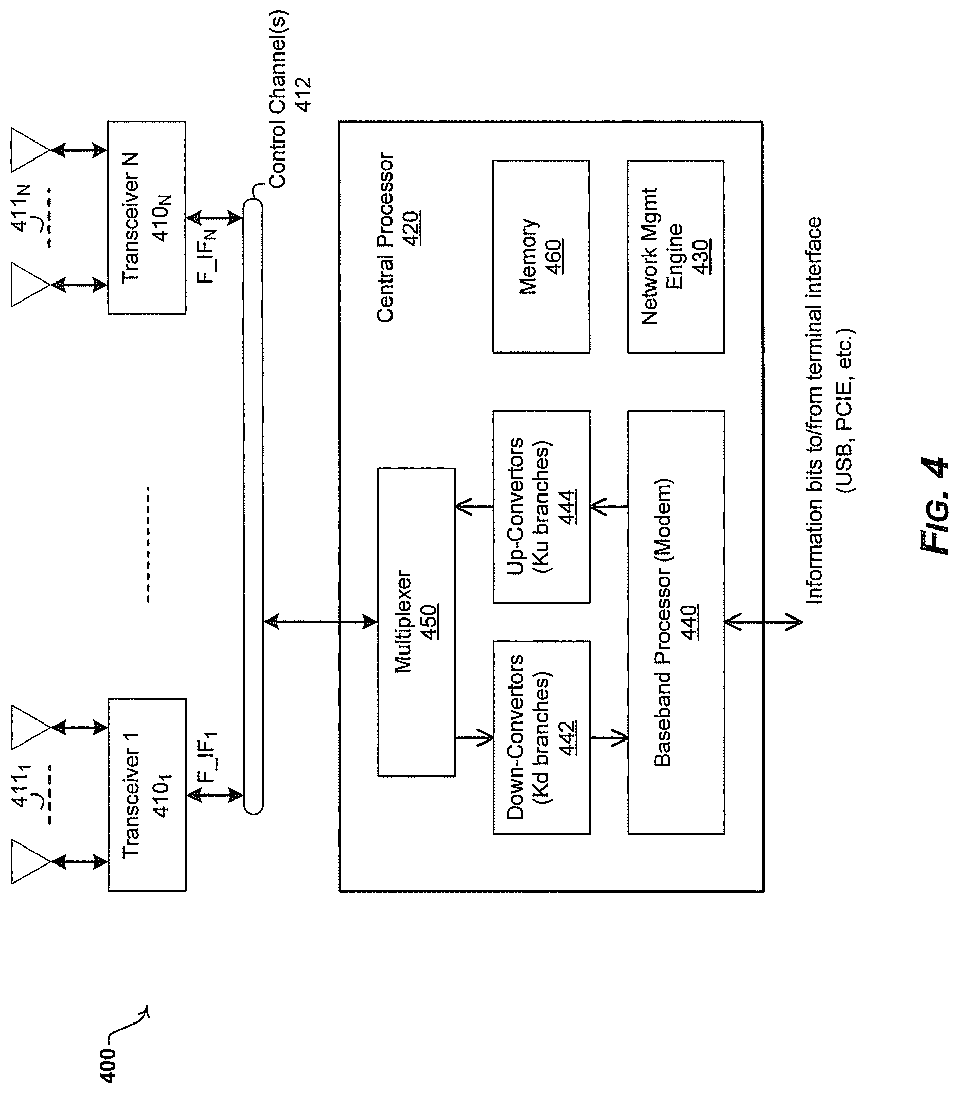
FIG. 4 is a diagram illustrating an exemplary application device with a collection of distributed transceivers, in accordance with an embodiment of the invention.
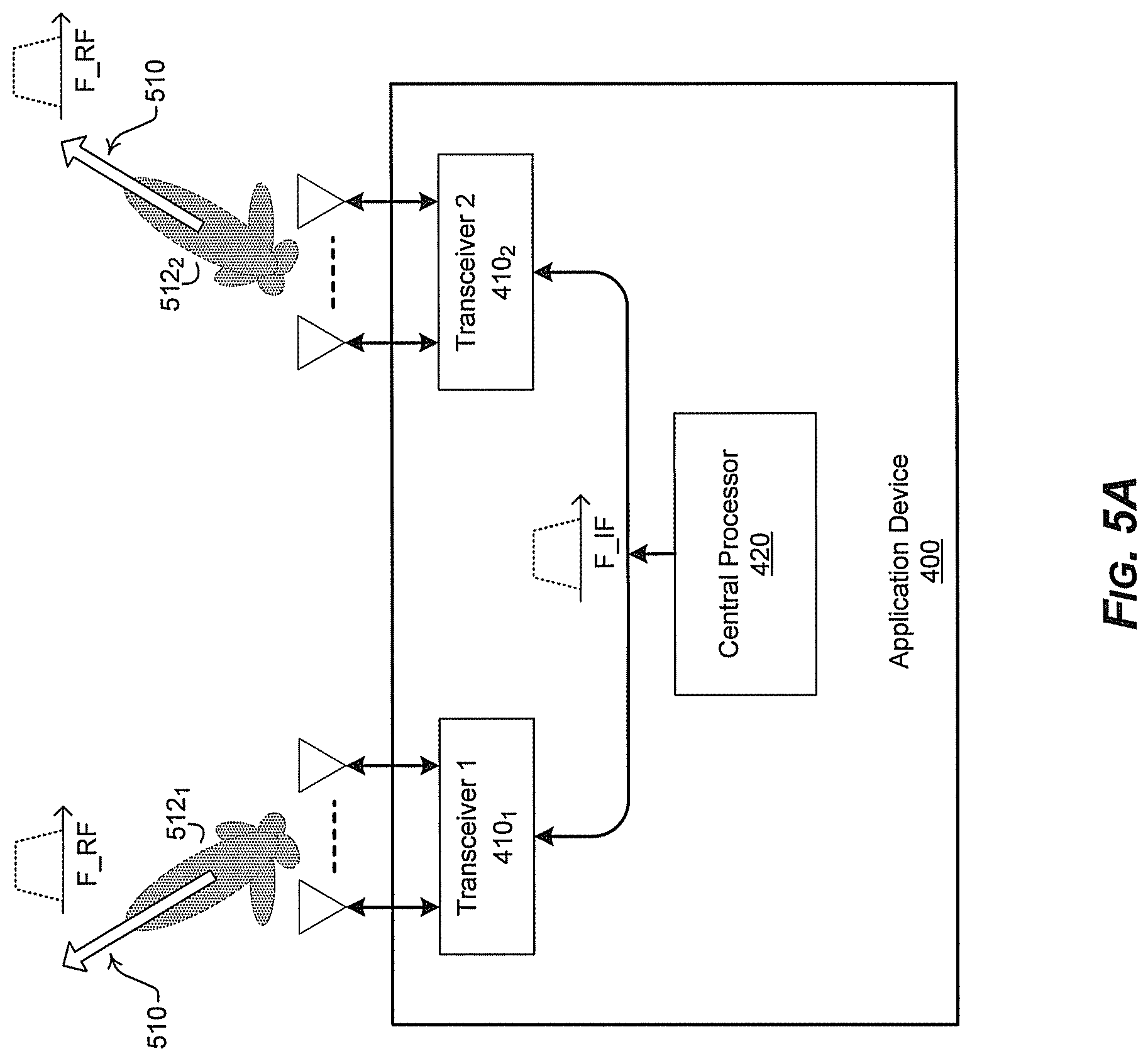
FIG. 5A is a diagram illustrating an exemplary application device that utilizes spatial diversity during communication via distributed transceivers, in accordance with an embodiment of the invention.
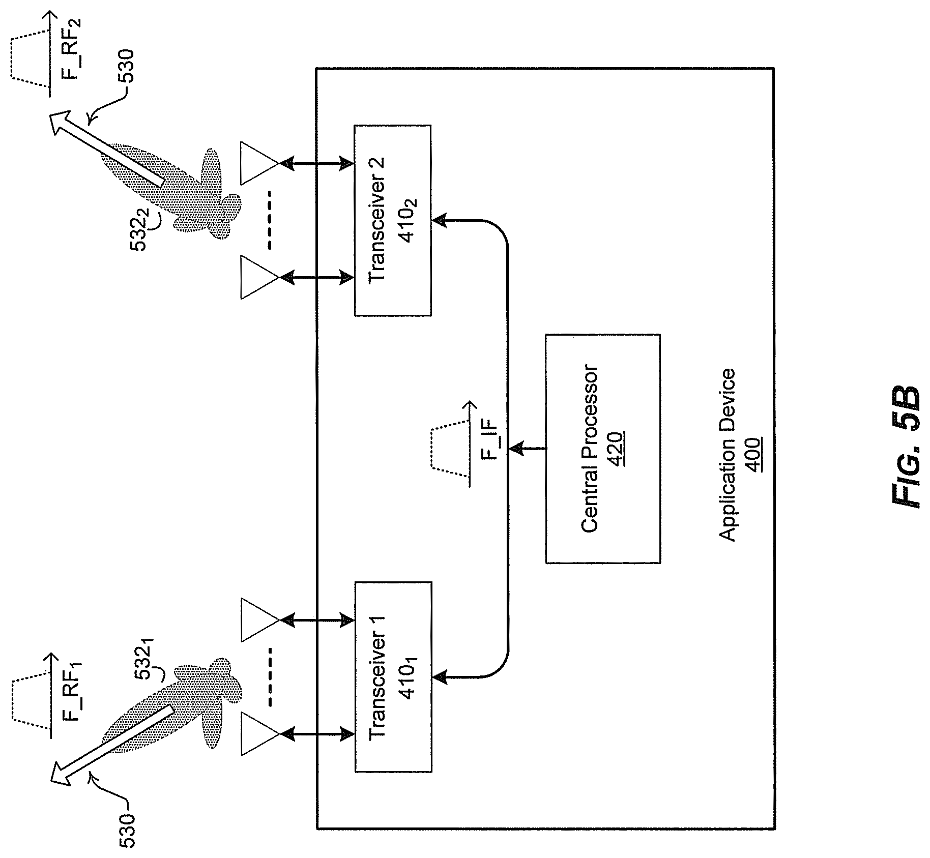
FIG. 5B is a diagram illustrating an exemplary application device that utilizes frequency diversity during communication via distributed transceivers, in accordance with an embodiment of the invention.
FIG. 6 is a flow chart that illustrates exemplary steps for configuring a device switch among a plurality of diversity modes of operations, and to switch in accordance with an embodiment of the invention.
DETAILED DESCRIPTION OF THE INVENTION
Certain embodiments of the invention may be found in a method and system for providing diversity in a network that utilizes distributed transceivers with array processing. In various embodiments of the invention, a communication device that comprises a plurality of distributed transceivers, a central processor and a network management engine may be configured to operate in one or more diversity modes. In this regard, configuring the communication device for diversity mode of operation may comprise configuring a plurality of communication modules (or blocks) from one or more of the plurality of distributed transceivers. The configuration may be based on a particular diversity mode, and each of the plurality of communication modules may comprise one or more antennas or antenna array elements, and one or more of the plurality of distributed transceivers associated with the one or more antennas or antenna array elements. The plurality of communication modules may then be utilized to concurrently communicate data streams from and/or to the communication device.
In some instances, each of the concurrently communicated data streams may comprise the same data--i.e., for redundant communication of the same data stream. The communication device may switch among a plurality of diversity modes, including during communication operations, and one or more of the plurality of communication modules may be reconfigured, dynamically, based on the switching. In this regard, the plurality of diversity modes may comprise spatial diversity mode, frequency diversity mode, and polarization diversity mode. The communication device may monitor a plurality of communication related parameters or conditions associated with and/or affecting the configuration of the plurality of communication modules. In this regard, the communication related parameters and/or conditions may pertain to link quality and/or propagation environment. The communication device may then select the diversity mode, to determine whether to switch to and/or incorporate another diversity mode, based on the monitoring. In some instances, the communication device may configure, based on the location of one or more reflectors, beamforming settings and/or antenna arrangement for one or more of the plurality of communication modules. Furthermore, the communication device may determine and/or select connection types and/or communication protocols that are used in establishing one or more links via the plurality of communication modules, for communicating the data streams. The communication device may allocate communication resources to the plurality of communication modules for use during the communication of the data streams. At least some of the allocated resources may be shared among the plurality of communication modules.
FIG. 1 is a block diagram illustrating an exemplary communication system that supports use and central management of distributed transceivers, in accordance with an embodiment of the invention. Referring to FIG. 1, there is shown a communication network 100 comprising a plurality of application devices, of which application devices 111-119 are displayed.
The application devices 111-119 may comprise suitable logic, circuitry, code, and/or interfaces that may be operable to communicate voice and data with one to another over wired and/or wireless connections. In an exemplary embodiment of the invention, each of the application devices 111-119 in the communication network 100 may comprise one or more distributed transceivers (DTs) for communication in the communication network 100. For example, distributed transceivers 111a through 119a may be integrated in the application devices 111 through 119, respectively, and utilized for receiving and transmitting signals. Each distributed transceiver may be equipped with an independently configurable antenna or antenna array that is operable to transmit and receive signals over the air. For example, the distributed transceivers 111a each may be equipped with an independently configurable antenna array 111b, and the distributed transceiver 118a, however, may be equipped with a single independently configurable antenna 118b to transmit and receive signals over the air. Depending on device capabilities and user preferences, distributed transceivers such as the distributed transceivers 111a within the application device 111, for example, may comprise radios such as a millimeter Wave (mmWave), a WLAN, WiMax, Bluetooth, Bluetooth Low Energy (BLE), cellular radios, WiMAX radio, or other types of radios. In this regard, radios such as mmWave radios may be utilized at very high carrier frequencies for high throughput wireless communications. Some devices may be conventional devices which may not utilize any distributed transceiver capability. In such cases, one end of the link may utilize distributed transceivers while the other end of the link does not do so (i.e., allowing for backward compatibility mode of operation, such as when communicating with legacy systems/devices).
In operation, the distributed transceivers 111a through 119a in the communication network 100 are physically positioned and oriented at different locations within corresponding application devices such like laptop, TV, gateway and/or set-top box. The distributed transceivers 111a through 119a may be centrally managed by a single network management engine (NME) 120 of the communication network 100. In an exemplary embodiment of the invention, the network management engine 120 may reside within a specific application device in the communication network 100. The network management engine 120 may be centralized as a full software implementation on a separate and/or remote network microprocessor, for example. In an exemplary embodiment of the invention, an application device in the communication network 100 may act or function as a master application device or an end-user application device. An application device that comprises the network management engine 120 and/or may have access to manage or control the network management engine 120 to dynamically configure and manage operation of the entire distributed transceivers in the communication network 100 is referred to a master application device. An application device that does not comprise the network management engine 120 and/or may have no access to manage or control the network management engine 120 is referred to as an end-user application device. The exchange of data/information required for network management operation may be performed over different links, such as 60 GHz, Bluetooth, and/or WLAN for example.
In some instances, the application device 111 acts as a master application device in the communication network 100. In an exemplary embodiment of the invention, the network management engine 120 in the master application device 111 may be utilized to configure, control, and manage the entire distributed transceivers 111a through 119a in the communication network 100 to optimize network performance. The application devices 111-119 each may operate in a transmission mode or in a receiving mode. In instances where the master application device 111 is transmitting multimedia information such as images, video, voice, as well as any other form of data to one or more receiving devices such as the end-user application devices 112-116, the network management engine 120 in the master application device 111 may be enabled to monitor and collect corresponding communication environment information from the end-user application devices 112-116. The collected communication environment information may comprise propagation environment conditions, link quality, device capabilities, antenna polarization, radiation pattern, antenna spacing, array geometry, device locations, target throughput, and/or application QoS requirements reported. The network management engine 120 may be operable to dynamically configure the distributed transceivers 111a-116a and associated antenna or antenna array 111b-116b, and to coordinate and manage the operation of the distributed transceivers 111a-116a and associated antenna or antenna array 111b-116b based on the collected communication environment information supplied from the end-user application devices 112-116. In this regard, the network management engine 120 may configure a single application device such as the application device 117 to maintain continuous connection with multiple different application devices such as the application devices 111-113.
The application device capabilities may comprise battery life, number of transceivers, number of antennas per transceiver, device interface types, processing protocols, service types, service classes and/or service requirements. The interface types for the application devices 111-119 may comprise access interface types such as Multimedia over Coax Alliance (MoCA), WiFi, Bluetooth, Ethernet, Femtocell, and/or cordless. The processing protocols may comprise service layer protocols, IP layer protocols and link layer protocols, as specified, for example, in the Open Systems Interconnect (OSI) model. The service layer protocols may comprise secure protocols such as Secure Socket Layer (SSL) and control protocols such as Spanning Tree Protocol (STP). The IP layer protocols may comprise IP signaling protocols such as SIP and H.323, and IP media transport protocols such as TCP, UDP, RTP, RTC and RTCP. The link layer protocols may comprise technology-specific PHY and MAC layer protocols such as, for example, Multimedia over Coax Alliance (MoCA), WiFi, Ethernet, Femtocell, and/or cordless.
Although communication among the application devices 111-119 with one or more distributed transceivers is illustrated in FIG. 1, the invention may not be so limited. Accordingly, an application device may be operable to utilize one or more associated distributed transceivers to communicate with one or more application devices with normal transceivers without departing from the spirit and scope of various embodiments of the invention.
In an exemplary aspect of the invention, the application devices 111-119 may be operable to utilize various diversity mechanisms, such as to reduce interference among distributed transceivers (or antennas) within these devices and/or to enhance communications between the devices. In this regard, the distributed transceivers of the application devices 111-119 may be configured to operate utilizing, for example, spatial diversity, frequency diversity, and/or polarization diversity. For example, a particular diversity mode may be selected, and the distributed transceivers, and/or their antennas, may be configured based the selected diversity mode, to enhance communication in each of the application devices 111-119 by reducing the interference among transceivers and/or antennas, and/or to optimize or enhance communication performance (e.g., link throughput or quality or reliability) and/or resource use. The selection of applicable diversity mode(s), and/or determining and/or setting various settings associated with the selected diversity mode(s) may be based on communication environment information, which may be collected by the network management engine 120.
In some embodiments, the distributed transceivers of the application devices 111-119 may be configured based on multiple diversity modes. For example, the distributed transceivers of a particular device (e.g., application device 111) may be configured such that the antennas utilized for each particular communication link have spatial diversity, frequency diversity, and polarization diversity compared to the remaining antennas of the device.
FIG. 2 is a diagram that illustrates an exemplary usage scenario where distributed transceivers are centrally managed to create a high-performance link between a transmitting device and one receiving device, in accordance with an embodiment of the invention. Referring to FIG. 2, there is shown a master application device 210 and an end-user application device 220.
The master application device 210 may comprise suitable logic, circuitry, interfaces and/or code that may be operable to communicate multimedia information such as images, video, voice, as well as any other forms of data with one or more application devices such as the end-user application device 220. The master application device 210 may comprise a collection of distributed transceivers 212a through 212e, and a central processor 217 that comprises a central baseband processor 214, a network management engine 216 and a memory 218. In an exemplary embodiment of the invention, each of the collection of distributed transceivers 212a through 212e may be physically positioned and oriented at different locations within an application device such as a laptop, TV, gateway, and set-top box. In this regard, the collection of distributed transceivers 212a through 212e may be implemented in various ways such as, for example, a single distributed transceiver integrated in a single chip package; multiple silicon dies on one single chip; and multiple distributed transceivers on a single silicon die. Depending on device capabilities and user preferences, the distributed transceivers 212a-212e may be oriented in a fixed direction or multiple different directions. In another exemplary embodiment of the invention, the collection of distributed transceivers 212a-212e may be operable to receive and/or transmit radio frequency signals from and/or to the end-user application device 220 using air interface protocols specified in UMTS, GSM, LTE, WLAN, 60 GHz/mmWave, and/or WiMAX, for example.
The end-user application device 220 may comprise suitable logic, circuitry, interfaces and/or code that may be operable to enable communication with other devices, such as the master application device 210. In this regard, the end-user application device 220 may be substantially similar to the master application device 210. For example, the end-user application device 220 may comprise transceivers 222 and 224, utilizing antennas (or antenna arrays) 222a-222n and 224a-224m, respectively, a baseband processor 226, and a memory 228.
The central baseband processor 214 may comprise suitable logic, circuitry, interfaces and/or code that may be operable to perform baseband digital signal processing needed for transmission and receiving operation of the entire collection of distributed transceivers 212a through 212e. For example, the central baseband processor 214 may be operable to perform waveform generation, equalization, channel encoding/decoding, beamforming processing, multi-input multi-output (MIMO) processing, and/or packet processing associated with the operation of the collection of distributed transceivers 212a through 212e. In addition, the central baseband processor 214 may be operable to configure, manage and control orientations of the distributed transceivers 212a-212e. The baseband processor 226 may be substantially similar to the central baseband processor 214.
The network management engine 216 may comprise suitable logic, circuitry, interfaces and/or code that may be operable to monitor and collect communication environment information such as propagation environment conditions, link quality, application device capabilities, transmitter/receiver locations, target throughput, and/or application QoS requirements. The network management engine 216 may utilize the collected communication environment information to configure system, network and communication environment conditions as needed. For example, the network management engine 216 may be operable to perform high level system configurations such as the number of transceivers that are activated, the number of application devices that are being communicated with, adding/dropping application devices to the communication network 100. As shown in FIG. 2, the network management engine 216 is residing in the master application device 210. However, in some embodiments the network management engine 216 may reside on different network devices such as separate network microprocessors and servers on the communication network 100. The network management engine 216 may comprise a full software implementation, for example. In addition, the functionality of the network management engine 216 may be distributed over several devices in the communication network 100. In some embodiments the network management engine 216 may be operable to manage communication sessions over the communication network 100. In this regard, the network management engine 216 may be operable to coordinate operation of baseband processors in the communication network 100 such that various baseband processing may be split or shared among the baseband processors. For example, the network management engine 216 may enable multiple central baseband processors for parallel baseband processing in order to increase throughput if needed.
The memory 218 may comprise suitable logic, circuitry, interfaces and/or code that may be operable to store information such as executable instructions and data that may be utilized by the central baseband processor 214 and/or other associated component units such as, for example, the network management engine 216. The memory 218 may comprise RAM, ROM, low latency nonvolatile memory such as flash memory and/or other suitable electronic data storage. The memory 228 may be substantially similar to the memory 218.
In an exemplary operation, a wireless link may be established between the master application device 210 and the end-user application device 220 through a reflector 230. In an exemplary embodiment of the invention, the master application device 210 may be operable to continuously scan the propagation environment to identify the directions and antenna patterns that result in strong reflected signals at the end-user application device 220. Then, the master application device 210 may associate each strong reflector with one of the collection of distributed transceivers 212a through 212e so as to transmit an independent different or same data stream to the end-user application device 220 over each distributed transceiver and through each strong reflector. For a reflector identified by the NME, transceiver (or transceivers) that may result in strongest signal transmission at the direction of the reflector, may be selected and/or configured at the reflector's direction. For example, the master application device 210 transmits two data streams to the end-user application device 220 using two different distributed transceivers 212a and 212d that may use the same frequency channel. In particular, the distributed transceivers 212a may choose a beam pattern 250 and orientation for a direct LOS to a transceiver 222, for example, of the end-user application device 220 (the receiving device) and transmit a first data stream over a carrier frequency RF.sub.1. On the other hand, the distributed transceivers 212d may choose a beam pattern 252 and orientation that is pointing towards the reflector 230 and transmit a second data stream also over the same carrier frequency RF.sub.1. The reflector 230 then may reflect the beam 252 towards a different transceiver 224 of the end-user application device 220. The selection of the beam patterns 250 and 252 may come from the central baseband processor 214 and the network management engine 216. In an exemplary embodiment of the invention, the central baseband processor 214 may profile channel energy for directions of arrival and other schemes. The network management engine 216 may know communication environment information such as the number of users, number of streams needed, and/or available frequency channels. For example, the central baseband processor 214 and the network management engine 216 may select narrow beams for close devices and may select wide beams for further devices, respectively.
In one embodiment of the invention, the master application device 210 may be operable to utilize the reflector 230 for the second data stream, for example, to lower the chances of an object blocking both the first and second data streams, simultaneously. In other words, if a big enough object blocks the LOS between the master application device 210 and the end-user application device 220, the second data stream may likely be intact and sustained by complete direct reflecting through a reflected path 252a. Although FIG. 2 shows one reflector 230, in one embodiment of the invention, several reflectors may be used to transmit one data stream or multiple data streams. The use of multiple reflectors may provide reflection diversification in case one reflector or a sub-set of reflectors are blocked. In other words, instead of directing all transmit power towards one reflector only, the total transmit power may be distributed to propagate over a set of "good" reflectors in the environment. This distribution of power over different reflectors may be done in a controlled, configurable, adaptive, and intelligent manner. For example, reflectors may be chosen and targeted that provide better orthogonality (e.g., to minimize cross interference) between the different paths.
In FIG. 2, the master application device 210 may use a second reflector at a different location and another distributed transceiver 212c, for example, to communicate with the end-user application device 220 and send a third data stream. Also the reflected path 252a may be caused by more than one reflector where, for example, the distributed transceiver 212e transmits towards the reflector 230 and the reflection transmits towards a second reflector and the reflection of the second reflector reaches the end-user application device 220. In another embodiment of the invention, the first and second data streams in FIG. 2 may comprise the same data content and the use of LOS path and one or more reflector paths may provide link robustness for data content in case an obstacle blocks some of the paths.
The master application device 210 may continuously monitor and collect propagation environment conditions, link quality, device capabilities, locations, target throughput, cross-interference between the paths, and/or application QoS requirements reported from the end-user application device 220. In this regard, a feedback or negotiation channel 240 may be utilized to exchange and negotiate system configurations such as number of transceivers within devices, number of antennas per transceivers, the measured channel responses, the sequence of antenna array coefficients being evaluated, and/or device location. The feedback or negotiation channel 240 may be implemented through a WLAN (e.g., Wi-Fi 802.11*link), Bluetooth link (over 2.4 GHz band), and/or 60 GHz link, for example
In some embodiments of the invention, the master application device 210 and/or the (slave) end-user application device 220 may deploy a plurality of baseband processors for implementing data processing requirements and/or demands. For example, multiple baseband processors may be deployed to generate and/or decode different data streams that may be transmitted or received by several distributed transceivers. In such configuration, the NME (e.g., NME 216) may be operable to control and/or coordinate operation of the multiple baseband processors. In this regard, several internal connection topologies may be used. In some embodiments of the invention, each baseband processor may be dedicated and/or assigned to a subset of distributed transceivers available in the system, and for each baseband processor, ring and/or star topologies (explained later) may be used in interacting with corresponding transceiver(s). In this regard, there may be no data transfer between the subsets. In another embodiment of the invention, however, all baseband processors and transceivers (within a device) may be connected together through a ring topology (single cable). In such scenario, the baseband processors may coordinate sharing the single cable, such as based on time-multiplexing (same IF frequency) or frequency-multiplexing (different IF frequencies). The baseband processors may have different power, processing, and/or communication characteristics. Accordingly, in some embodiments of the invention, the baseband processor that is most suitable for a particular mode of operation (e.g., lower power consumption meeting the throughput requirement) may be selected and activated, with the other baseband processors remaining inactive and/or getting disabled.
FIG. 3 is a diagram that illustrates an exemplary transceiver module, in accordance with an embodiment of the invention. Referring to FIG. 3, there is shown a transceiver 300 comprising an antenna array 310, an antenna array with/without antenna combiner 320, down-converters 330, up-converters 340, and a multiplexer 350.
In an exemplary operation, the antenna array 310 may comprise suitable logic, circuitry, interfaces and/or code that may be operable to transmit and receive radio frequency (RF) signals over the air. For transmission the transceiver 300 may be operable to receive a transmit signal from the central baseband processor 214. The transmit signal received from the central baseband processor 214 may be up-converted to RF frequency via the up-converters 340. For reception, the transceiver 300 may pass a receive signal from the antenna array 310 after down-conversion to the central baseband processor 214. The multiplexer 350 may comprise suitable logic, circuitry, interfaces and/or code that may be operable to multiplex the transmit signal received from the central baseband processor 214 and the receive signal supplied from the antenna array 310. In this regard, the multiplexer 350 may utilize either time-division-multiplexing or frequency-domain-multiplexing to communicate the transmit signal and the receive signal over the same medium such as a cable.
The antenna array with/without antenna combiner 320 may comprise suitable logic, circuitry, interfaces and/or code that may be operable to scale and/or phase-shift signals before the down-converters 330 and/or signals after the up-converters 340. For example, in transmission operation the signal provided by the up-converters 340 may be phase-shifted by the shifter by different values. The resulting phase-shifted signals may be fed to different antenna elements within the antenna array 310. In another embodiment of the invention, the antenna array 310 may be oriented in a fixed direction or multiple different directions depending on antenna types and user preferences. For example, the antenna array 310 may be implemented as a fixed directional antenna array to provide maximal directionality (with no explicit combiner). The same two modules, that is, the antenna array 310 and the antenna array with/without antenna combiner 320, may be correspondingly utilized in a reception operation for the transceiver 300. In an exemplary embodiment of the invention, the operation of the antenna array with/without antenna combiner 320 may be managed or programmed by the network management engine 216.
The down-converters 330 may comprise suitable logic, circuitry, interfaces and/or code that may be operable to translate a radio frequency (RF) received from the antenna array 310 to an intermediate-frequency (IF) signal during reception. The up-converters 340 may comprise suitable logic, circuitry, interfaces and/or code that may be operable to translate an intermediate-frequency (IF) signal of a corresponding baseband signal supplied from the central baseband processor 214, for example to a RF signal during transmission. In some embodiments, the IF frequency may be the same as the RF frequency (no frequency conversion), or the IF frequency may be equivalent to zero frequency (baseband frequency).
FIG. 4 is a diagram illustrating an exemplary application device with a collection of distributed transceivers, in accordance with an embodiment of the invention. Referring to FIG. 4, there is shown an application device 400, which may comprise a central processor 420 that is connected to a collection of distributed transceivers 410.sub.1-410.sub.N.
The distributed transceivers 410.sub.1-410.sub.N and the central processor 420 may be connected using different topologies. For example, the distributed transceivers 410.sub.1-410.sub.N may be connected to the central processor 420 using a star topology, whereby direct separate cables may be used, for example, to connect the central processor 420 to each of the collection of transceivers 410.sub.1-410.sub.N. Alternatively, a ring topology may be utilized, whereby a single movable cable or connector, for example, may be used to couple the central processor 420 to any particular one of the distributed transceivers 410.sub.1-410.sub.N at any given point. In other words, the central processor 420 may connect to one of the distributed transceivers 410.sub.1-410.sub.N, and that connection may then be moved to a different transceiver when needed. One or more control channels between the central processor 420 and the distributed transceivers 410.sub.1-410.sub.N may be utilized for configuring and managing corresponding transceivers. The number and/or structure of the control channels may differ based on the connectivity topology. For example, with star topology, a plurality of control channels 412.sub.1-412.sub.N may be to connect the central processor 420 to each of the distributed transceivers 410.sub.1-410.sub.N, and may be utilized for configuring and managing the transceivers 410.sub.1-410.sub.N, respectively. In a ring topology, a single control channel 412 may be used, and may be utilized to the central processor 420 to each particular distributed transceiver 410.sub.x at any given point, to enable configuring and managing that transceiver.
While the interface between the central processor 420 and the distributed transceivers 410.sub.1-410.sub.N may be described as utilizing cable (i.e., the central processor 420 being connected to the distributed transceivers 410.sub.1-410.sub.N via one or more cables), the invention may not be so limited. Accordingly, in some embodiments, the cable connection between the central baseband processor and the distributed transceivers may be substituted with an optical connection, printed-board connection, Ethernet cable, or another wireless connection.
The central processor 420 comprises a baseband processor 440, a network management engine 430, down-converters 442, up-converters 444, a multiplexer 450 and a memory 460. The baseband processor 440 may comprise suitable logic, circuitry, interfaces and/or code that may be operable to provide MODEM functionality. In this regard, the central processor 420 may be operable to perform various baseband digital processing such as MIMO, OFDM, channel coding, HARQ, channel estimation and equalization, Timing/Carrier recovery and synchronization. The network management engine 430 may operate in substantially the same manner as the network management engine 218 in FIG. 2. During transmission, a baseband signal supplied from the baseband processor 440 may be translated into an intermediate-frequency (IF) signal. The up-converters 444 may further translate the IF signal to a final radio-frequency (RF) and send it over the air through an antenna array such as the antenna array 411.sub.1. For reception, the transceiver 410.sub.1, for example, may pass a received RF signal from the antenna array 411.sub.1 to the down-converters 442. The down-converters 442 may translate the RF signal into an IF signal. The IF signal may further be translated to a baseband signal to the baseband processor 440, for example. The multiplexer 450 may be responsible for multiplexing receive/transmit signals utilizing either time-division-multiplexing or frequency-domain-multiplexing. The memory 460 may comprise suitable logic, circuitry, interfaces and/or code that may be operable to store information such as executable instructions and data that may be utilized by the baseband processor 440 and/or other associated component units such as, for example, the network management engine 430. The memory 360 may comprise RAM, ROM, low latency nonvolatile memory such as flash memory and/or other suitable electronic data storage.
In some embodiments of the invention, the interface between the central processor 420 and the distributed transceivers 410.sub.1-410.sub.N may also be configured to support the transceivers 410.sub.1-410.sub.N having digital processing and mixed-signal capability--i.e., to allow for interactions based on non-analog IF connections. For example, the transceivers 410.sub.1-410.sub.N may comprise analog-to-digital-converters (ADCs) and digital-to-analog-converters (DACs). In such scenario, a transceiver 410.sub.x may receive digital bits from the central processor 420 (through a digital link), after processing via the baseband processor 440 for example, and may use its internal DAC to generate the analog waveform and then perform the frequency up-conversion and beamforming steps. Similarly, a transceiver 410.sub.x may receive an RF waveform, down-convert it, and then use its internal ADC to digitize the waveform and send the digital bits over a digital connection/cable to the centralized processor 420 (where it may be further processed via the baseband processor 440 for example). In other embodiments of the invention, the transceivers 410.sub.1-410.sub.N may comprise more digital processing blocks, in addition to ADC/DAC blocks. In such scenario, a portion of processing within the central processor 420 may be moved (e.g., in terms of partitioning) to the transceivers 410.sub.1-410.sub.N. In the above embodiments of the invention--i.e., when there may be need for digital based interfacing between the central processor and the transceivers--digital connections and/or interfaces such as Ethernet and various memory bus protocols may be deployed.
The distributed transceivers 410.sub.1-410.sub.N may operate in various modes such as spatial diversity mode, frequency diversity mode, multiplexing mode, multiple-input-multiple-output (MIMO) mode, and/or relay mode. Furthermore, in some embodiments, the distributed transceivers 410.sub.1-410.sub.N may be configured to switch between spatial diversity mode, frequency diversity mode, multiplexing mode, multiple-input-multiple-output (MIMO) mode, and/or relay mode based on corresponding propagation environment conditions, link quality, device capabilities, device locations, usage of resources, resource availability, target throughput, cross-interference between paths or transceiver pairs, and application QoS requirements.
In spatial diversity mode, the central processor 420 may be operable to utilize the distributed transceivers 410.sub.1-410.sub.N to establish a spatial diversity link with intended end user device such as the end-user application device 220. For example, only a portion of the distributed transceivers 410.sub.1-410.sub.N that may have strong propagation channel responses are activated and other transceivers are switched off for power saving. In another example, the distributed transceivers 410.sub.1-410.sub.N may be arranged such that the master application device 210 (the transmitter) with available LOS towards the end-user device 220 (the receiver) may be configured to directly beam towards the receiver. In an exemplary embodiment of the invention, each active distributed transceiver may communicate data streams utilizing the same final carrier frequency. In frequency diversity mode, the central processor 420 may manage the distributed transceivers 410.sub.1-410.sub.N similar to spatial diversity mode except that each active distributed transceiver may utilize a different final carrier frequency if such frequency spectrum channel is available. In some embodiments, the central processor 420 may also be operable to configure the distributed transceivers 410.sub.1-410.sub.N in accordance with a polarization diversity mode. In this regard, the central processor 420 may be operable to configure the distributed transceivers 410.sub.1-410.sub.N to establish a plurality of modules and/or links with intended end user devices having varying antenna polarization. For example, the central processor 420 may configure the antennas and/or antenna arrays (or subsets thereof) of each of the distributed transceivers 410.sub.1-410.sub.N with different antenna polarizations to achieve antenna polarization diversification. In this regard, antenna polarization refers to the orientation of the electric field of the radio wave transmitted (or may be received) by an antenna. Accordingly, applying varying antenna polarization to each of the distributed transceivers 410.sub.1-410.sub.N may enable receiving and/or transmitting signals by different distributed transceivers, each with a different polarization, and thus may reduce the interference therebetween--i.e., signals transmitted, by a particular antenna (or group of antennas) configured at antenna polarization P1, would not be received by a second antenna configured at different polarization P2, and as such would not interfere with signal reception at the second antenna.
In multiplexing mode, the central processor 420 may manage the distributed transceivers 410.sub.1-410.sub.N in such a way that different streams of data may be transmitted through different sets of the distributed transceivers 410.sub.1-410.sub.N (e.g., for improved effective throughput). For example, in multiplexing mode, different distributed transceivers of the distributed transceivers 410.sub.1-410.sub.N may be dynamically programmed such that each transceiver's maximum pattern gain may be pointing to a different direction or reflector. As the environment changes (and hence location of reflectors and end user unit change), the antenna pattern of the distributed transceivers 410.sub.1-410.sub.N may be re-adjusted. In MIMO mode, the central processor 420 may manage the distributed transceivers 410.sub.1-410.sub.N in such a way that different streams of data may be transmitted through different sets of the distributed transceivers 410.sub.1-410.sub.N to a single receiver device such as the end-user application device 220.
In relay mode, the central processor 420 may manage the distributed transceivers 410.sub.1-410.sub.N to support relay mode of operation, whereby the application device 400 may be utilized in relaying data streams between two other devices. In this regard, the star topology implementation may particularly be suited for relay operations, enabling reception of input data stream from a first device, via a first set of the distributed transceivers 410.sub.1-410.sub.N, and (re)transmission of the received data stream to a second device via a second set of the distributed transceivers 410.sub.1-410.sub.N. The selection of the first and second sets of the distributed transceivers 410.sub.1-410.sub.N, and the configuration thereof may be performed adaptively and/or dynamically. In this regard, the transceivers utilized in receiving and/or transmitting the relayed streams may be select such that to optimize the relaying operation performed. This may comprise, for example, selecting and/or configuring the transceivers such that radio frequencies and/or channels may be reused efficiently. For example, use of beamforming may enable mitigating potential interference between incoming and outgoing signals as to allow using the same radio frequency (RF) (e.g., for maximal reuse or utilization of frequency spectrum). In other words, the same RF channel/spectrum may be reused in manner that may allow for maintaining links with the two end devices utilizing physically separated transceivers that may use non-overlapping antenna patterns to minimize interference. Furthermore, the transceiver(s) maybe be configured as to use only some of the antennas available therein (e.g., subset of the antenna array), and/or may allow for use of transceivers without array processing. If cross interference between the incoming and outgoing waveforms is detected to be higher than a threshold, the NME may then configure the transceivers to use different final RF frequencies for incoming and outgoing waveforms.
In an embodiment of the invention, the application device 400 may utilize the various diversity modes available therein, such as to reduce interference among the distributed transceivers 410.sub.1-410.sub.N and/or antennas thereof, to enhance quality and/or communication performance, and/or to optimize resource utilization in the application device 400. For example, the distributed transceivers 410.sub.1-410.sub.N and/or antennas of the application device 400 may be configured based on, for example, spatial diversity, frequency diversity, and/or polarization diversity. For example, a particular diversity mode may be selected, and the distributed transceivers 410.sub.1-410.sub.N may be configured based the selected diversity mode, to enable enhancing communication in the application device 400 by reducing the interference between individual ones of the distributed transceivers 410.sub.1-410.sub.N. In this regard, configuring a particular transceiver and/or antenna(s) associated therewith for spatial diversity mode may comprise specifying beamforming settings that ensure signals transmitted or received have particular, and typically narrow directionality. With frequency diversity mode, the configuration may comprise specifying particular frequency and/or channels used for transmitting or receiving signals, and with polarization diversity mode, the configuration may comprise specifying and/or applying particular antenna polarization settings.
In some instances, diversity modes of operations may comprise adaptive selection and/or configuration of groups of antennas, some of which may comprise only subset of antennas of a particular transceiver (e.g., grouping of only some of the antennas of the distributed transceiver 410.sub.1) while other groups may span antennas of more than one transceiver (e.g., grouping of all of the antennas of the distributed transceiver 410.sub.1 and some of the antennas of the distributed transceiver 410.sub.N). In this regard, rather than simply configuring individual transceivers, the diversity mode may comprise dynamic forming of communication blocks which may adaptively combine particular antennas (or antenna arrays) in the application device 400, along with one or more transceivers (e.g., transceivers connected to the selected antennas), with each of the communication blocks being configured separately and/or adaptively in accordance with the applicable diversity mode.
In some embodiments of the invention, the distributed transceivers 410.sub.1-410.sub.N of the application device 400 may be configured in accordance with multiple diversity modes. For example, the distributed transceivers 410.sub.1-410.sub.N may be configured such that each distributed transceiver 410.sub.x and/or each antenna grouping may have spatial diversity, frequency diversity, and polarization diversity. In some instances, additional mechanisms may be incorporated into the diversity modes of operation to further enhance performance and/or efficiency in the devices and/or communication environment. For example, the application device 400 may apply channel coding during communication of data streams by configured transceivers, and/or may utilize frequency hopping to optimize frequency spectrum utilization. In this regard, channel coding may be used to protect communicated data (especially during wireless communication) against unwanted access, and/or to ensure that the communicated data may be received and/or extracted properly even in the presence of noise (errors) in the communication environment. Channel coding may comprise applying forward error correction and/or bit interleaving, such as using convolutional and/or block based coding schemes, to communicated data. Channel coding may also comprise use of space-time coding (STC), such as when multiple, redundant copies of a data stream are communicated via multiple configured communication blocks.
Configuring and/or utilizing diversity modes of operation may require coordinating at least certain aspects of the operations between the devices. For example, the application device 400 may establish low-throughput high-fidelity channels (e.g., over Bluetooth, WLAN, low data rate no-beamforming 60 GHz link, etc.), such as the feedback or negotiation channel 240, with target devices to communicate and negotiate system configuration related information, used for establishing and/or using high-throughput links. For example, the application device 400 may utilize such channels when selecting and/or negotiating parameters which may be utilized for configuring and/or applying diversity modes of operation. The application device 400 may use the feedback or negotiation channel 240 to communicate with the target device(s) to select and/or negotiate, for example, parameters relating to configuration of frequency and/or channel, directionality, antenna polarization, and/or timing.
FIG. 5A is a diagram illustrating an exemplary application device that utilizes spatial diversity during communication via distributed transceivers, in accordance with an embodiment of the invention. Referring to FIG. 5A, there is shown the application device 400 of FIG. 4.
As shown in FIG. 5A, the application device 400 may be configured in accordance with spatial diversity mode of operation. In this regard, during spatial diversity mode of operation, when establishing and/or managing communication links between the application device 400 and other devices, the central processor 420 may configure the distributed transceivers 410.sub.1-410.sub.N such that transceivers and/or antennas (or groupings thereof) utilized for each communication link may exhibit spatial diversity relative to remaining transceivers and/or antennas. In this regard, the communication links may correspond to communication blocks, with each communication block corresponding to a particular communication link, and comprising one or more of the distributed transceivers 410.sub.1-410.sub.N and/or one or more antennas. In some instances, each of the communication blocks may be associated with a particular group of antennas. In this regard, antennas (or antenna arrays) of the distributed transceivers 410.sub.1-410.sub.N, may be grouped, with each group of antennas having a unique and spatially diverse beamforming setting and/or antenna arrangement, such that signals corresponding to a particular communication link may be transmitted and/or received in narrow and directional beams that are spatially positioned so that they do not overlap and/or intersect with signals of other communication links that are transmitted or received by other groups of antennas.
The antennas may be grouped dynamically and/or adaptively, whereby antenna groups may comprise only antennas (or antenna arrays) of individual transceivers (e.g., a grouping of only some or all of the antennas of the distributed transceiver 410.sub.1), and/or may comprise antennas spanning multiple transceivers (e.g., a grouping of some or all of the antennas of the transceiver 410.sub.1 and some or all of the antennas of the transceiver 410.sub.2).
Use of spatial diversity may enable improving and/or enhancing the communication links and/or communication operations in the application devices. The improvements may be, for example, in the form of higher link throughput, longer range, and/or lower power consumption. For example, configuring the distributed transceivers 410.sub.1-410.sub.N in accordance with spatial diversity mode may reduce potential interference between the communication links, thus requiring less transmit power (i.e., reducing power consumption).
In an embodiment of the invention, spatial diversity may be utilized to enhance communication robustness and reliability. For example, multiple transceivers and/or groups of antennas may be configured to establish a plurality of spatially diverse communication links to the same receiving device, and these communication links may then be used to communicate the same data. These communication links comprise direct and/or indirect links. In this regard, during spatial diversity mode of operation, the same signal may be communicated to the transceivers, and the signal may then be communicated in different, non-overlapping directions. In other words, each transceiver (or group of antennas) may be configured with a distinct beamforming and/or antenna arrangement, and the copies of the same signals are transmitted such that if one signal path is blocked, the signal may still be received via path(s) that are not be blocked.
For example, for transmission of data stream 510, a first transceiver, such as the transceiver 410.sub.1 which may have direct LOS towards the target receiving device, may be configured (based on its antennas arrangement and/or the beamforming settings specified via the central processor 420) to form and/or utilize a particular directional beam pattern 512.sub.1, which may enable transmitting signals (or beams) directly towards the target receiving device. In addition, another transceiver, such as the transceiver 410.sub.2, may be configured to form and/or utilize a particular directional beam pattern 512.sub.2, which may enable transmitting signals (or beams) at a different direction, to transmit the same data stream 510 indirectly towards the target receiving device, such as through an available strong reflector. Using such redundant but spatially diverse communication links may provide the system with diversity against shadowing and/or blocking. For example, if a large obstacle blocks the LOS path, the indirect reflector path will likely be intact and sustained through the reflector. To further improve the performance, several reflectors may be chosen--in case one reflector or several reflectors are blocked, and multiple transceivers (or communication blocks) may be configured corresponding to the LOS path (if available) and to reflectors. In this regard, reflectors that provide better orthogonality between the different paths may be chosen and targeted. In some embodiments of the invention, the directional beams of a multiple transmission blocks (e.g., M transmission blocks) may be configured towards the top M reflecting points (in terms of strength of reflected signals) in the environment. In this regard, the application device 400 may identify and utilize reflectors present in the communication environment, comprising implanted reflectors or random existing reflectors.
On the receiving side, different schemes are used during redundant communication, depending on the capabilities of the receiving device for example, for supporting reception and/or handling of multiple beams carrying the same data stream (510). For example, if the receiving device is capable of configuring a sufficient number of communication blocks (e.g., it comprises a sufficient number of transceivers, with appropriate antenna arrangements), then each receiving module's beam pattern may be directed toward one of the plurality of reflecting points (e.g., one of the M reflecting points). Thus, multiple (M) reflected signals may be collected by the receiving device separately (hence resulting in minimal interference between different received reflections). Alternatively, if the receiving device cannot configure a sufficient number of communication blocks (e.g., it comprises only one transceiver), then the receiver beam pattern(s) may be configured to receive combined collection(s) of reflected received signals. In this case, although there may be interferences between the received reflections, the total received signal power over all reflections may still be maximized. The receiving device may then apply (via its own central processor, for example) equalization to mitigate the effects of inter-symbol-interference.
In an embodiment of the invention, only transceivers that may be determined to have strong propagation channel responses may be activated, with the other transceivers being switched off for power saving. For example, the application device 400 (e.g., via the central processor 420) may identify that transceiver 410.sub.1 has the best LOS link to the target device (due to blocking objects in the room or nature of reflectors in the room). In this case only transceiver 410.sub.1 may be switched on to transmit data stream 510, with the other transceivers (of which only transceiver 410.sub.1 is shown) may be switched off for power saving. In some embodiments, within a transceiver module with multiple antennas, the central processor (420) may conclude that a subset of antennas within a transceiver is sufficient to deliver a target performance. In this case, the other antenna and corresponding blocks within the transceiver are switched off for further power saving.
In an embodiment of the invention, different transceivers, each with its own antenna array pattern, may be physically positioned and/or oriented at different locations within an application device such that the transceivers (and their antennas/antenna arrays) may be sufficiently separated to minimize the chances of having all transceivers blocked by an object between the two communicating units. Furthermore, each transceiver may be oriented such that its antenna array plane (and hence its maximum antenna array gain) may be pointing in a different direction compared to the other transceivers. This may provide maximum directional diversity, such that for any possible wireless link direction (e.g., to another device), there may be at least one transceiver covering that direction with a high antenna beam pattern gain. For example, in instances where the application device 400 comprises 4 transceivers (i.e., N being 4 in this case), a target spherical coverage may be partitioned into 4 relatively equal regions, and each of the transceivers 410.sub.1-410.sub.4 may be physically installed within the application device 400, and/or oriented to cover a separate region with a high antenna beam pattern gain. In some embodiments, the relative and absolute orientation of transceivers 410.sub.1-410.sub.4 is based on individual antenna patterns of transceivers 410.sub.1-410.sub.4 if those transceivers are not identical. For instance, one transceiver may have a wide main antenna pattern lobe while others have narrower primary lobes. In such usage cases, the transceivers are physically mounted and fine-tuned to provide full coverage of space with minimal overlap of antenna patterns.
FIG. 5B is a diagram illustrating an exemplary application device that utilized frequency diversity during communication via distributed transceivers, in accordance with an embodiment of the invention. Referring to FIG. 5A, there is shown the application device 400 of FIG. 4.
As shown in FIG. 5B, the application device 400 may be configured in accordance with frequency diversity mode of operation. In this regard, during frequency diversity mode of operation, when establishing and/or managing communication links between the application device 400 and other devices, the central processor 420 may configure the distributed transceivers 410.sub.1-410.sub.N such that transceivers and/or antennas (or groupings thereof) utilized for each communication links may use different carrier radio frequency (RF) for the transmitted signals. In this regard, the communication links may correspond to communication blocks, with each module being configured to use a unique RF, which may be selected such that transmitted and/or received signals, for each communication link, may be separated at the receiving side from signals pertaining to the remaining links, which may be treated (based on having a different RF) as background noise.
In an embodiment of the invention, frequency diversity may be used to enhance communication robustness and reliability by communicating the same data to a particular receiving device, via multiple communication links each having a different RF. For example, the central processor 420 may configure the transceivers 410.sub.1 and 410.sub.2 to utilize two different RF carrier frequencies, F_RF.sub.1 and F_RF.sub.2, when transmitting and/or receiving signals. In this regard, when transmitting the data stream 530, the same intermediate frequency (IF) data corresponding to the data stream 530 may be up-converted via transceivers 410.sub.1 and 410.sub.2 into the two different RF carrier frequencies, F_RF.sub.1 and F_RF.sub.2, which may then be used in transmitting the data stream 530 to the same target receiving device. Thus, the transmitted signal streams exhibit frequency diversity, which may mitigate inter-symbol interference (ISI) between the signal streams transmitted by the two the transceivers 410.sub.1 and 410.sub.2. In some instances, the receiving device may be configured such that different communication blocks may be used to receive the signal streams. In other words, two of the communication blocks at the receiving device may be configured to tune in to carrier frequencies (F_RF.sub.1 and F_RF.sub.2) used at the transmitting side. Additionally, this feature may provide diversity against poor propagation channel response at one of the frequencies (e.g., becoming especially useful for narrowband communications). For example, if F_RF.sub.1 happens to experience a poor (e.g., deep fading) channel response, F_RF.sub.2 may be less likely to experience the same poor or deep fading propagation response.
In an embodiment of the invention, frequency diversity may be combined with other diversity modes. For example, to further enhance robustness of the links--e.g., to physical objects blocking the link--spatial diversity may also be incorporated into the configuration of transceivers being configured for frequency diversity mode of operation. In the previous example, this may be achieved by configuring the transceiver 410.sub.1 (e.g., based on selection and/or arrangement of antenna(s) and/or beamforming settings) such that, in addition to utilizing carrier frequency F_RF.sub.1, its antennas (or any subset thereof) may have a directional beam pattern 532.sub.1 which may be tuned for maximum gain in a particular direction D1. At the same time, the transceiver 410.sub.2, which utilizes carrier frequency F_RF.sub.2, may be configured (e.g., based on selection and/or arrangement of antenna(s) and/or beamforming settings) such that its antennas (or any subset thereof) may have a directional beam pattern 532.sub.2 which may be tuned for maximum gain at a different direction D2. The directions D1 and D2 may be chosen such that the transmitted signals may be directed to the same receiving device using different paths, to provide additional spatial diversity to the link, in addition to the frequency diversity. The different paths may correspond to two different reflection points or objects. Alternatively, one of the paths may correspond to direct LOS transmission. Incorporating varying directionality may ensure that at least one of the transmitted streams may be received, such as when the other stream (e.g., corresponding to direction D1) is blocked by an object.
FIG. 6 is a flow chart that illustrates exemplary steps for configuring a device switch among a plurality of diversity modes of operations, in accordance with an embodiment of the invention. Referring to FIG. 6, there is shown a flow chart 600 comprising a plurality of exemplary steps for performing applying and/or switching among a plurality of diversity modes in an application device, such as the application device 400.
In step 602, an application device, such as the application device 400, may establish control connection(s) with one or more target devices. For example, the application device 400 may establish the low-throughput high-fidelity channels with the target devices, which may be utilized to coordinate communications between the application device 400 and the target device(s). In this regard, the control connections may be utilized for communicating and negotiating system configurations used for high-throughput links. In step 604, a diversity mode of operation may be selected by the application device. In instances where the selected diversity mode of operation is a spatial diversity (SD) mode, the process may proceed to step 606.
In step 606, the application device may establish high-throughput, spatial diversity mode based link(s) to the target device(s). In this regard, each of the established links may exhibit unique (and to the extent possible orthogonal) spatial directionality. In step 608, the established link(s) to the other device may be optimized based on spatial diversity mode. In this regard, the links may be optimized based on continuous monitoring of link quality, device capabilities, and/or communication environment, cross-interference between the established spatial links, and/or based on detection of any changes thereof. Optimizing established links may comprise, for example reconfiguring communication components--e.g., reconfiguring the transceivers and/or antenna arrangements and/or adjusting beam forming settings. For example, the optimization procedure may comprise selecting the best transceiver(s) for each link. The application device may choose, for example, transceivers that may have better antenna pattern gains towards the target device(s) and/or transceivers that may provide maximally separated directions of transmissions (e.g., to minimize cross-interference between different transmissions). In other words, the optimization procedure may seek to achieve maximum reflection (or LOS) and directional diversity. In the spatial diversity mode, the application device may reuse the same RF carrier frequency for all active transceiver modules. The same RF carrier frequency usage may typically be considered by the NME, such as in scenarios where achieving a better spectral efficiency (e.g., through reuse of spectrum) may be a performance target. In some instances, however, multiple RF carrier frequencies may be utilized, thus incorporating elements of frequency diversity.
In step 610, it may be determined whether to switch diversity modes. Controlling switching among the modes may be based on the monitoring of link quality, device capabilities and/or communication environment, and/or detection of any changes therein. For example, the application device may determine, based on monitoring of channel conditions, dominant reflectors' positions, and/or the communication environment, whether it should switch to a frequency diversity mode and/or a polarization diversity mode. To determine whether to switch to the frequency diversity mode for example, the application device may regularly or dynamically monitor frequency channel conditions and availability. If no other frequency channels are available, the application device may continue to operate in the spatial diversity mode, and may continue to optimize the spatial diversity mode. If other frequency channels become available, however, the application device may have the option of switching to the frequency diversity mode. In determining whether to make the switch, the application device may examine or utilize other parameters such as the level of inter-symbol-interference (ISI), overlap between the antenna patterns of different active transceivers, as well as requests for higher quality-of-service (QoS) or throughput. For example, if other frequency channels are available and a better QoS is requested or ISI is too high, then unit A switches to the frequency diversity mode.
In instances where there is no switch in diversity modes, the process may return to step 608. In instances where it is determined that there need be a switch to frequency diversity (FD) mode, the process may jump to step 612. The switch to frequency diversity mode may require the application device to switch some of its transceivers to other RF carrier frequencies, which may have become available. This may help eliminate and/or reduce cross-interference between the waveforms transmitted by different transceivers. In instances where it is determined that there need be a switch to polarization diversity (PD) mode, the process may jump to step 618. The switch may require reconfiguring the transceivers and/or antennas, to modify the antenna polarization.
Returning to step 604, in instances where the selected diversity mode of operation is frequency diversity (FD) mode, the process may proceed to step 612. In step 612, the application device may establish high-throughput, frequency diversity mode based link(s) to the target device(s). In this regard, the application device may select one or more transceivers that may be suited for establishing frequency diversity mode links, where each of the established links may utilize a different RF carrier frequency. In the frequency diversity mode, the RF carrier frequencies of active transceivers may be selected and/or configured for maximal frequency diversity. For example, the RF carrier frequencies may be selected in order to mitigate interference (e.g., ISI) at the receiving side because of the different transmissions. Additionally, as in the spatial diversity mode, in some instances in the frequency diversity mode, the beam patterns and directionality of active transceivers may be selected and/or configured for optimal reflection and/or directionality. In step 614, the established link(s) may be optimized based on the frequency diversity mode. In this regard, the links may be optimized by dynamically or continually monitoring link quality, device capabilities, and/or communication environment, to detect any changes, and may reconfigure the communication components--e.g., reselect and/or reconfigure the transceivers and/or antennas, and/or modify frequency and/or channel selections.
In step 616, it may be determined whether to switch diversity modes, such as based on the parameters and/or conditions relating to link quality, device capabilities and/or communication environment, and/or based on any changes thereof. For example, while in the frequency diversity mode, the application device may regularly or dynamically monitor channel conditions and the communication environment, to determine whether it should switch to the spatial diversity mode and/or the polarization diversity mode. To determine whether to the switch to the spatial diversity mode, for example, the application device may determine, based on monitoring of channel conditions and/or the communication environment, whether it should switch to the spatial diversity mode (to conserve spectrum usage and be a good neighbor). For example, the application device may regularly monitor demand for frequency channels by other devices in the vicinity (since the application device is occupying multiple frequency channels in this mode). If other devices are requesting frequency spectrum, the application device may choose to switch to the spatial diversity mode where it may only use one frequency, thus freeing up remaining frequencies. Likewise, if the application device and the target device(s) can maintain their desired throughput and/or quality using less frequency channels (e.g. QoS is higher than required, ISI has gone down, changes in environment, channel, or throughput requirements, etc.) then the application device may switch back to spatial diversity mode. If, however, the application device determines that it should continue operating in the frequency diversity mode, and frequency channels are available, the application device may keep on optimizing frequency diversity mode parameters, and may also incorporate additional diversity optimization measures, such as optimizing the spatial directionality and/or antenna polarization of at least certain transceivers, even though they are operating at different RF carrier frequencies.
In instances where it is determined that no switch in diversity modes should occur, the process may return to step 614. In instances where it is determined that a switch to the spatial diversity (SD) mode should occur, the process may jump to step 608. In instances where it is determined that there need be a switch to the polarization diversity (PD) mode, the process may jump to step 618.
Returning to step 604, in instances where the selected diversity mode of operation is the polarization diversity (PD) mode, the process may proceed to step 618. In step 618, the application device may establish high-throughput, polarization diversity mode link(s) to the target device(s). In this regard, each of the established links may be associated with a particular antenna polarization. The antenna polarization settings may be selected in order to ensure that there would be less interference at the receiving side because of the different transmissions. In step 620, the established link(s) may be optimized based on the polarization diversity mode. In this regard, the links may be optimized based on dynamic or continuous monitoring of link quality, device capabilities, and/or communication environment, and/or based on detection of any changes therein. Optimizing established links may comprise, for example, reconfiguring communication components--e.g., reconfiguring the transceivers and/or antenna arrangements to adjust and/or modify antenna polarization settings applicable thereto. In step 622, it may be determined whether to switch diversity modes, such as based on the parameters and/or conditions relating to link quality, device capabilities and/or communication environment, and/or based on any changes therein. In instances where it is determined that no switch in diversity modes should occur, the process may return to step 620. In instances where it is determined that there should be a switch to the spatial diversity (SD) mode, the process may jump to step 608. In instances where it is determined that there should be a switch to the frequency diversity (FD) mode, the process may jump to step 612.
Various embodiments of the invention may comprise a method and system for providing diversity in a network that utilizes distributed transceivers with array processing. The application device 400 may be configured to operate in one or more diversity modes of operations, which may comprise a spatial diversity mode, a frequency diversity mode, and/or a polarization diversity mode. In this regard, configuring the application device 400 for a particular diversity mode of operation may comprise configuring, based on the diversity mode, a plurality of communication blocks from one or more of the plurality of distributed transceivers 410.sub.1-410.sub.N, with each of the plurality of communication blocks comprising one or more antennas and/or antenna array elements, and at least one of that distributed transceivers 410.sub.1-410.sub.N that may be associated with the antenna(s) and/or antenna array element(s). The plurality of communication blocks may then be utilized to concurrently communicate data streams from and/or to the application device 400. In some instances, each of the concurrently communicated data streams may comprise the same data--i.e., for redundant communication of the same data stream. The application device 400 may switch among the plurality of diversity modes, including during communication operations, and one or more of the plurality of communication blocks may be reconfigured, dynamically, based on the switching.
The application device 400 may continuously monitor and/or collect, using the network management engine 430 for example, communication related information, such as propagation environment conditions, link quality, device capabilities, locations, target throughput, and/or application QoS requirements. The application device 400 may then select based on the monitoring, a diversity mode that the application device 400 may switch to and/or incorporate into its communication operations. In some instances, the application device 400 may configure, based on a location of one or more reflectors (e.g., reflector 230), beamforming settings and/or antenna arrangement for one or more of the plurality of communication blocks. Furthermore, the application device 400 may determine and/or select connection types and/or communication protocols that may be utilized for establishing one or more links via the plurality of communication blocks, for communicating the data streams. The application device 400 may allocate communication resources (e.g., up-convertors 442, down-convertors 444, and/or memory 460) to the plurality of communication blocks for use during the communication of the data streams. At least some of the allocated resources may be shared among the plurality of communication blocks.
Other embodiments of the invention may provide a non-transitory computer readable medium and/or storage medium, and/or a non-transitory machine readable medium and/or storage medium, having stored thereon, a machine code and/or a computer program having at least one code section executable by a machine and/or a computer, thereby causing the machine and/or computer to perform the steps as described herein for providing diversity in a network that utilizes distributed transceivers with array processing.
Accordingly, the present invention may be realized in hardware, software, or a combination of hardware and software. The present invention may be realized in a centralized fashion in at least one computer system, or in a distributed fashion where different elements are spread across several interconnected computer systems. Any kind of computer system or other system adapted for carrying out the methods described herein is suited. A typical combination of hardware and software may be a general-purpose computer system with a computer program that, when being loaded and executed, controls the computer system such that it carries out the methods described herein.
The present invention may also be embedded in a computer program product, which comprises all the features enabling the implementation of the methods described herein, and which when loaded in a computer system is able to carry out these methods. Computer program in the present context means any expression, in any language, code or notation, of a set of instructions intended to cause a system having an information processing capability to perform a particular function either directly or after either or both of the following: a) conversion to another language, code or notation; b) reproduction in a different material form.
While the present invention has been described with reference to certain embodiments, it will be understood by those skilled in the art that various changes may be made and equivalents may be substituted without departing from the scope of the present invention. In addition, many modifications may be made to adapt a particular situation or material to the teachings of the present invention without departing from its scope. Therefore, it is intended that the present invention not be limited to the particular embodiment disclosed, but that the present invention will include all embodiments falling within the scope of the appended claims.
* * * * *
D00000
D00001
D00002
D00003
D00004
D00005
D00006
D00007
XML
uspto.report is an independent third-party trademark research tool that is not affiliated, endorsed, or sponsored by the United States Patent and Trademark Office (USPTO) or any other governmental organization. The information provided by uspto.report is based on publicly available data at the time of writing and is intended for informational purposes only.
While we strive to provide accurate and up-to-date information, we do not guarantee the accuracy, completeness, reliability, or suitability of the information displayed on this site. The use of this site is at your own risk. Any reliance you place on such information is therefore strictly at your own risk.
All official trademark data, including owner information, should be verified by visiting the official USPTO website at www.uspto.gov. This site is not intended to replace professional legal advice and should not be used as a substitute for consulting with a legal professional who is knowledgeable about trademark law.