Camera optical lens
Teranishi , et al. December 22, 2
U.S. patent number 10,871,636 [Application Number 16/530,999] was granted by the patent office on 2020-12-22 for camera optical lens. This patent grant is currently assigned to AAC Optics Solutions Pte. Ltd.. The grantee listed for this patent is AAC Technologies Pte. Ltd.. Invention is credited to Yaqiong Guo, Takaaki Teranishi, Yanmei Wang, Lei Zhang.


| United States Patent | 10,871,636 |
| Teranishi , et al. | December 22, 2020 |
Camera optical lens
Abstract
The present disclosure discloses a camera optical lens. The camera optical lens including, in an order from an object side to an image side, a first lens, a second lens having a positive refractive power, a third lens having a positive refractive power, a fourth lens, a fifth lens, and a sixth lens. The first lens is made of plastic material, the second lens is made of glass material, the third lens is made of plastic material, the fourth lens is made of plastic material, the fifth lens is made of glass material, and the sixth lens is made of plastic material. The camera optical lens further satisfies specific conditions.
| Inventors: | Teranishi; Takaaki (Shenzhen, CN), Zhang; Lei (Shenzhen, CN), Wang; Yanmei (Shenzhen, CN), Guo; Yaqiong (Shenzhen, CN) | ||||||||||
|---|---|---|---|---|---|---|---|---|---|---|---|
| Applicant: |
|
||||||||||
| Assignee: | AAC Optics Solutions Pte. Ltd.
(Singapore, SG) |
||||||||||
| Family ID: | 1000005257222 | ||||||||||
| Appl. No.: | 16/530,999 | ||||||||||
| Filed: | August 2, 2019 |
Prior Publication Data
| Document Identifier | Publication Date | |
|---|---|---|
| US 20200057275 A1 | Feb 20, 2020 | |
Foreign Application Priority Data
| Aug 14, 2018 [CN] | 2018 1 0925245 | |||
| Aug 14, 2018 [CN] | 2018 1 0925257 | |||
| Current U.S. Class: | 1/1 |
| Current CPC Class: | H04N 5/23212 (20130101); G02B 13/0045 (20130101); G02B 7/102 (20130101) |
| Current International Class: | G02B 13/00 (20060101); G02B 7/10 (20060101); H04N 5/232 (20060101) |
References Cited [Referenced By]
U.S. Patent Documents
| 2020/0057269 | February 2020 | Teranishi |
| 2020/0057270 | February 2020 | Oinuma |
| 2020/0057272 | February 2020 | Teranishi |
| 2020/0057273 | February 2020 | Teranishi |
| 2020/0057274 | February 2020 | Oinuma |
| 2020/0057275 | February 2020 | Teranishi |
| 2020/0057278 | February 2020 | Teranishi |
| 2020/0057279 | February 2020 | Teranishi |
| 1975138824 | Nov 1975 | JP | |||
| 1979099428 | Aug 1979 | JP | |||
| 2007199612 | Aug 2007 | JP | |||
| 2010039014 | Feb 2010 | JP | |||
| 2010102083 | May 2010 | JP | |||
| 2014142403 | Aug 2014 | JP | |||
| 2015057641 | Mar 2015 | JP | |||
| 2017125904 | Jul 2017 | JP | |||
| 1020060107651 | Oct 2006 | KR | |||
| 100711116 | Apr 2007 | KR | |||
Other References
|
1st Office Action dated Nov. 7, 2019 by SIPO in related Chinese Patent Application No. 201810925245.3 (7 Pages). cited by applicant . 1st Office Action dated Oct. 28, 2019 by SIPO in related Chinese Patent Application No. 201810925257.6 (6 Pages). cited by applicant . 1st Office Action dated Jan. 28, 2019 in related Japanese Patent Application No. 2018166467 (8 Pages). cited by applicant. |
Primary Examiner: Perkey; William B
Attorney, Agent or Firm: W&G Law Group LLP
Claims
What is claimed is:
1. A camera optical lens comprising, from an object side to an image side in sequence: a first lens, a second lens having a positive refractive power, a third lens having a positive refractive power, a fourth lens, a fifth lens, and a sixth lens; wherein the camera optical lens further satisfies the following conditions: -2.749.ltoreq.f1/f.ltoreq.-1.261; 1.71.ltoreq.n2.ltoreq.2.052; 1.709.ltoreq.n5.ltoreq.2.062; 0.041.ltoreq.d3/TTL.ltoreq.0.058; where f: the focal length of the camera optical lens; f1: the focal length of the first lens; n2: the refractive index of the second lens; n5: the refractive index of the fifth lens; d3: the thickness on-axis of the second lens; TTL: the total distance from the object side surface of the first lens to the image plane along the optic axis.
2. The camera optical lens as described in claim 1, wherein the first lens is made of plastic material, the second lens is made of glass material, the third lens is made of plastic material, the fourth lens is made of plastic material, the fifth lens is made of glass material, the sixth lens is made of plastic material.
3. The camera optical lens as described in claim 1, wherein first lens has a negative refractive power with a convex object side surface relative to the proximal axis and a concave image side surface relative to the proximal axis; the camera optical lens further satisfies the following conditions: 2.27.ltoreq.(R1+R2)/(R1-R2).ltoreq.8.61; 0.02.ltoreq.d1/TTL.ltoreq.0.07; where R1: the curvature radius of object side surface of the first lens; R2: the curvature radius of image side surface of the first lens; d1: the thickness on-axis of the first lens.
4. The camera optical lens as described in claim 3 further satisfying the following conditions: 3.63.ltoreq.(R1+R2)/(R1-R2).ltoreq.6.89; 0.03.ltoreq.d1/TTL.ltoreq.0.05.
5. The camera optical lens as described in claim 1, wherein the second lens has a convex object side surface relative to the proximal axis and a concave image side surface relative to the proximal axis; the camera optical lens further satisfies the following conditions: 0.58.ltoreq.f2/f.ltoreq.2.31; -6.67.ltoreq.(R3+R4)/(R3-R4).ltoreq.-1.68; where f2: the focal length of the second lens; R3: the curvature radius of the object side surface of the second lens; R4: the curvature radius of the image side surface of the second lens.
6. The camera optical lens as described in claim 5 further satisfying the following conditions: 0.93.ltoreq.f2/f.ltoreq.1.85; -4.17.ltoreq.(R3+R4)/(R3-R4).ltoreq.-2.10.
7. The camera optical lens as described in claim 1, wherein the third lens has a convex object side surface relative to the proximal axis; the camera optical lens further satisfies the following conditions: 0.62.ltoreq.f3/f.ltoreq.2.07; -2.19.ltoreq.(R5+R6)/(R5-R6).ltoreq.-0.51; 0.05.ltoreq.d5/TTL.ltoreq.0.16; where f3: the focal length of the third lens; R5: the curvature radius of the object side surface of the third lens; R6: the curvature radius of the image side surface of the third lens; d5: the thickness on-axis of the third lens.
8. The camera optical lens as described in claim 7 further satisfying the following conditions: 0.99.ltoreq.f3/f.ltoreq.1.66; -1.37.ltoreq.(R5+R6)/(R5-R6).ltoreq.-0.64; 0.08.ltoreq.d5/TTL.ltoreq.0.12.
9. The camera optical lens as described in claim 1, wherein the fourth lens has a positive refractive power with a concave object side surface relative to the proximal axis and a convex image side surface relative to the proximal axis; the camera optical lens further satisfies the following conditions: 0.79.ltoreq.f4/f.ltoreq.2.60; 0.87.ltoreq.(R7+R8)/(R7-R8).ltoreq.2.95; 0.04.ltoreq.d7/TTL.ltoreq.0.14; where f4: the focal length of the fourth lens; R7: the curvature radius of the object side surface of the fourth lens; R8: the curvature radius of the image side surface of the fourth lens; d7: the thickness on-axis of the fourth lens.
10. The camera optical lens as described in claim 9 further satisfying the following conditions: 1.26.ltoreq.f4/f.ltoreq.2.08; 1.39.ltoreq.(R7+R8)/(R7-R8).ltoreq.2.36; 0.06.ltoreq.d7/TTL.ltoreq.0.11.
11. The camera optical lens as described in claim 1, wherein the fifth lens has a negative refractive power with a concave object side surface relative to the proximal axis and a convex image side surface relative to the proximal axis; the camera optical lens further satisfies the following conditions: -2.65.ltoreq.f5/f.ltoreq.-0.75; -11.94.ltoreq.(R9+R10)/(R9-R10).ltoreq.-3.37; 0.02.ltoreq.d9/TTL.ltoreq.0.09; where f5: the focal length of the fifth lens; R9: the curvature radius of the object side surface of the fifth lens; R10: the curvature radius of the image side surface of the fifth lens; d9: the thickness on-axis of the fifth lens.
12. The camera optical lens as described in claim 11 further satisfying the following conditions: -1.66.ltoreq.f5/f.ltoreq.-0.94; -7.46.ltoreq.(R9+R10)/(R9-R10).ltoreq.-4.22; 0.04.ltoreq.d9/TTL.ltoreq.0.08.
13. The camera optical lens as described in claim 1, wherein the sixth lens has a positive refractive power with a convex object side surface relative to the proximal axis and a concave image side surface relative to the proximal axis; the camera optical lens further satisfies the following conditions: 1.49.ltoreq.f6/f.ltoreq.5.79; -75.96.ltoreq.(R11+R12)/(R11-R12).ltoreq.1439.02; 0.10.ltoreq.d11/TTL.ltoreq.0.32; where f6: the focal length of the sixth lens; R11: the curvature radius of the object side surface of the sixth lens; R12: the curvature radius of the image side surface of the sixth lens; d11: the thickness on-axis of the sixth lens.
14. The camera optical lens as described in claim 13 further satisfying the following conditions: 2.39.ltoreq.f6/f.ltoreq.4.63; -47.78.ltoreq.(R11+R12)/(R11-R12).ltoreq.1151.22; 0.16.ltoreq.d11/TTL.ltoreq.0.26.
15. The camera optical lens as described in claim 1 further satisfying the following condition: 2.30.ltoreq.f12/f.ltoreq.9.90; where f12: the combined focal length of the first lens and the second lens.
16. The camera optical lens as described in claim 15 further satisfying the following condition: 3.69.ltoreq.f12/f.ltoreq.7.92.
17. The camera optical lens as described in claim 1, wherein the total distance from the object side surface of the first lens to the image plane along the optic axis is less than or equal to 5.17 mm.
18. The camera optical lens as described in claim 1, wherein the aperture F number of the camera optical lens is less than or equal to 2.27.
19. The camera optical lens as described in claim 18, wherein the aperture F number of the camera optical lens is less than or equal to 2.22.
Description
FIELD OF THE PRESENT DISCLOSURE
The present disclosure relates to optical lens, in particular to a camera optical lens suitable for handheld devices such as smart phones and digital cameras and imaging devices.
DESCRIPTION OF RELATED ART
With the emergence of smart phones in recent years, the demand for miniature camera lens is increasing day by day, but the photosensitive devices of general camera lens are no other than Charge Coupled Device (CCD) or Complementary metal-Oxide Semiconductor Sensor (CMOS sensor), and as the progress of the semiconductor manufacturing technology makes the pixel size of the photosensitive devices shrink, coupled with the current development trend of electronic products being that their functions should be better and their shape should be thin and small, miniature camera lens with good imaging quality therefor has become a mainstream in the market. In order to obtain better imaging quality, the lens that is traditionally equipped in mobile phone cameras adopts a three-piece or four-piece lens structure. And, with the development of technology and the increase of the diverse demands of users, and under this circumstances that the pixel area of photosensitive devices is shrinking steadily and the requirement of the system for the imaging quality is improving constantly, the five-piece, six-piece and seven-piece lens structure gradually appear in lens design. There is an urgent need for ultra-thin wide-angle camera lenses which have good optical characteristics and the chromatic aberration of which is fully corrected.
BRIEF DESCRIPTION OF THE DRAWINGS
Many aspects of the exemplary embodiments can be better understood with reference to the following drawings. The components in the drawing are not necessarily drawn to scale, the emphasis instead being placed upon clearly illustrating the principles of the present disclosure.
FIG. 1 is a schematic diagram of a camera optical lens in accordance with a first embodiment of the present invention;
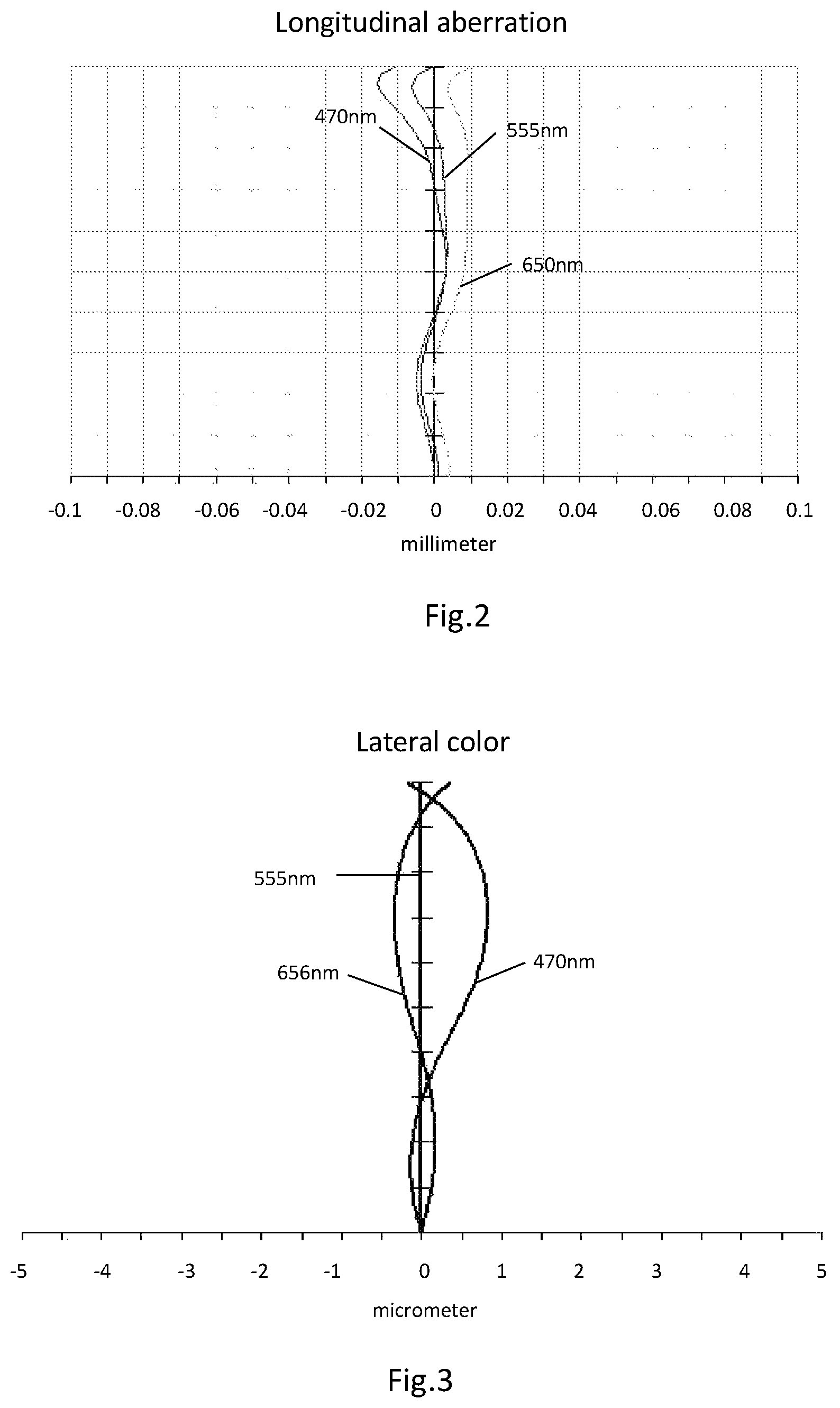
FIG. 2 presents the longitudinal aberration of the camera optical lens shown in FIG. 1;
FIG. 3 presents the lateral color of the camera optical lens shown in FIG. 1;
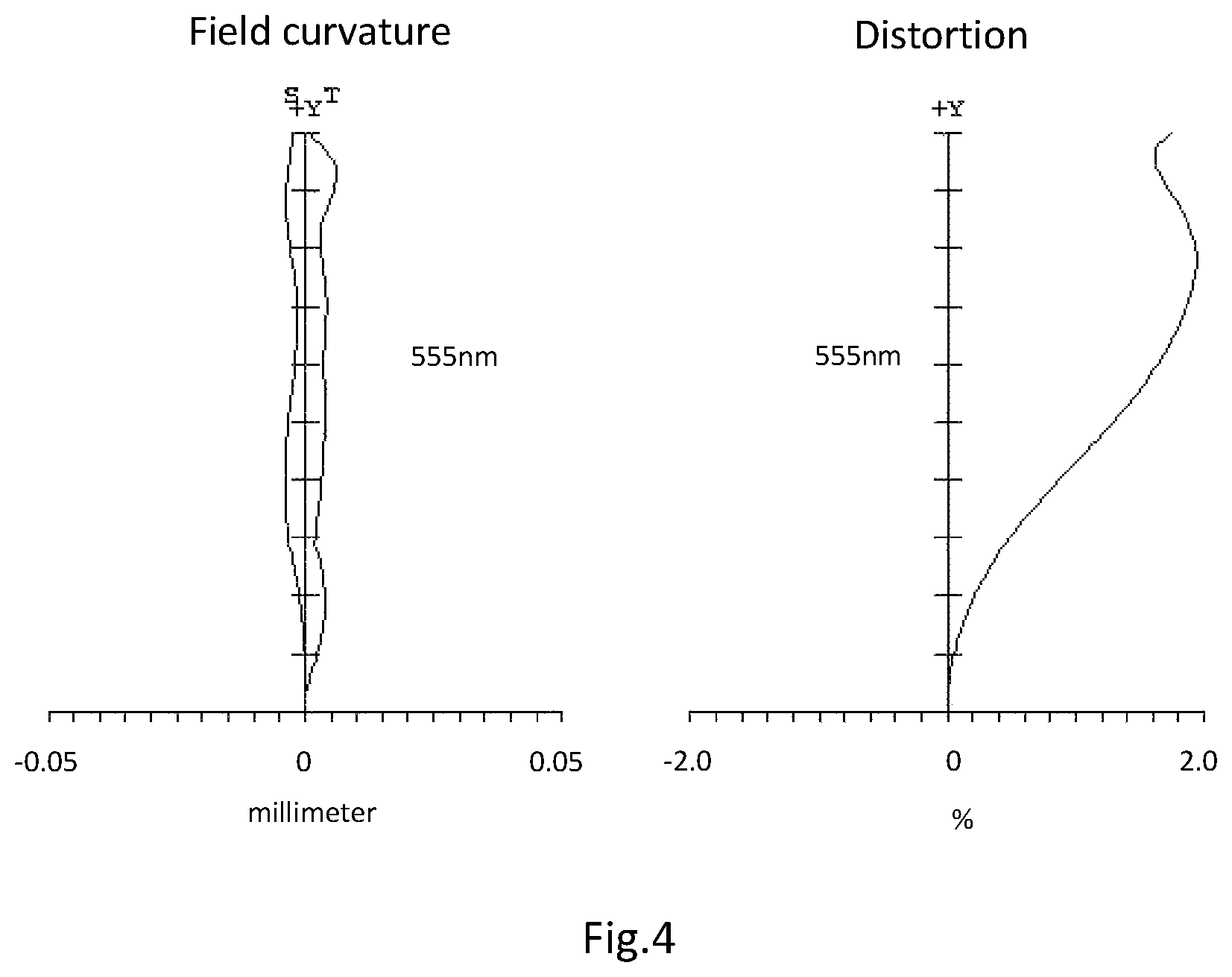
FIG. 4 presents the field curvature and distortion of the camera optical lens shown in FIG. 1;
FIG. 5 is a schematic diagram of a camera optical lens in accordance with a second embodiment of the present invention;
FIG. 6 presents the longitudinal aberration of the camera optical lens shown in FIG. 5;
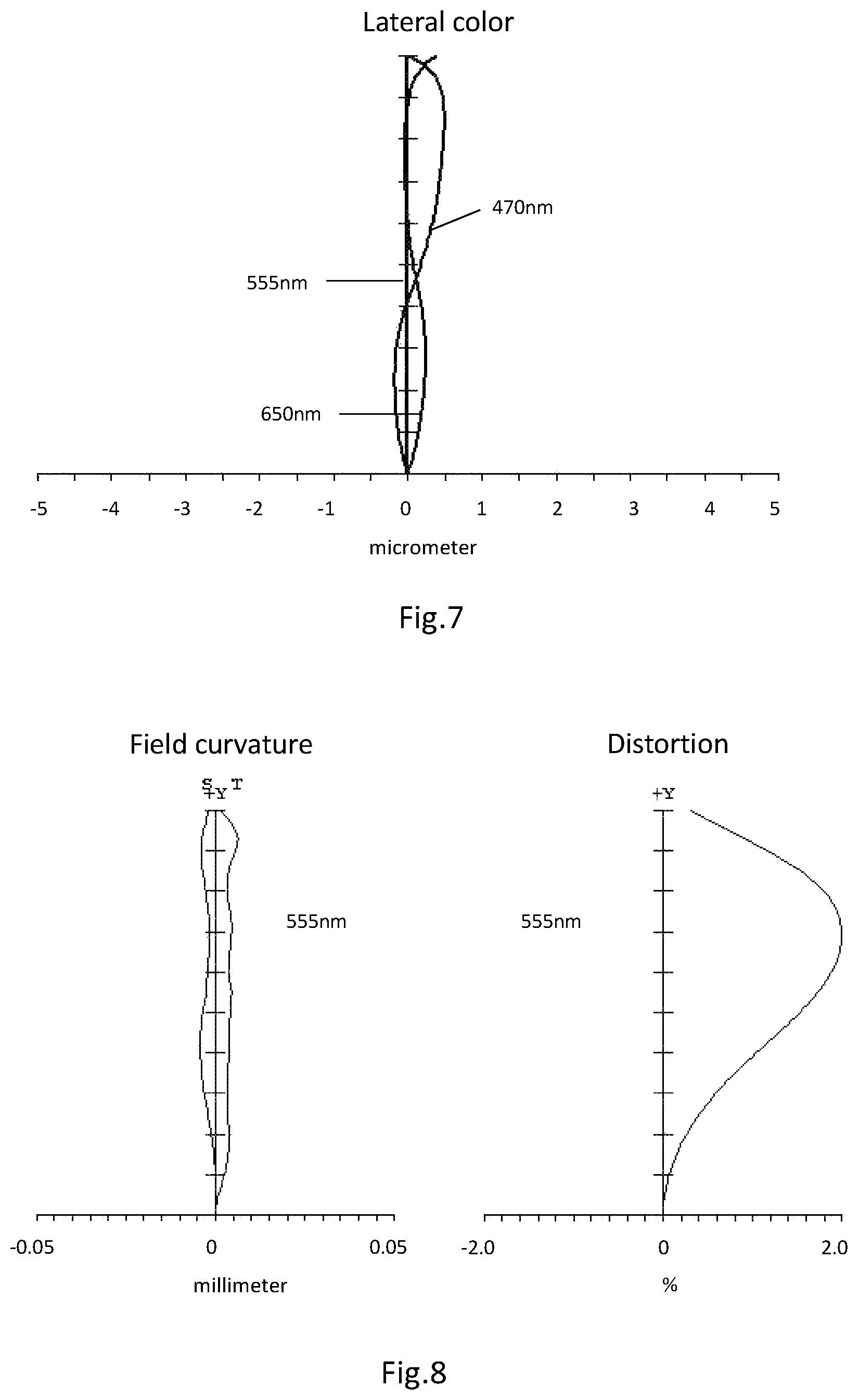
FIG. 7 presents the lateral color of the camera optical lens shown in FIG. 5;
FIG. 8 presents the field curvature and distortion of the camera optical lens shown in FIG. 5;
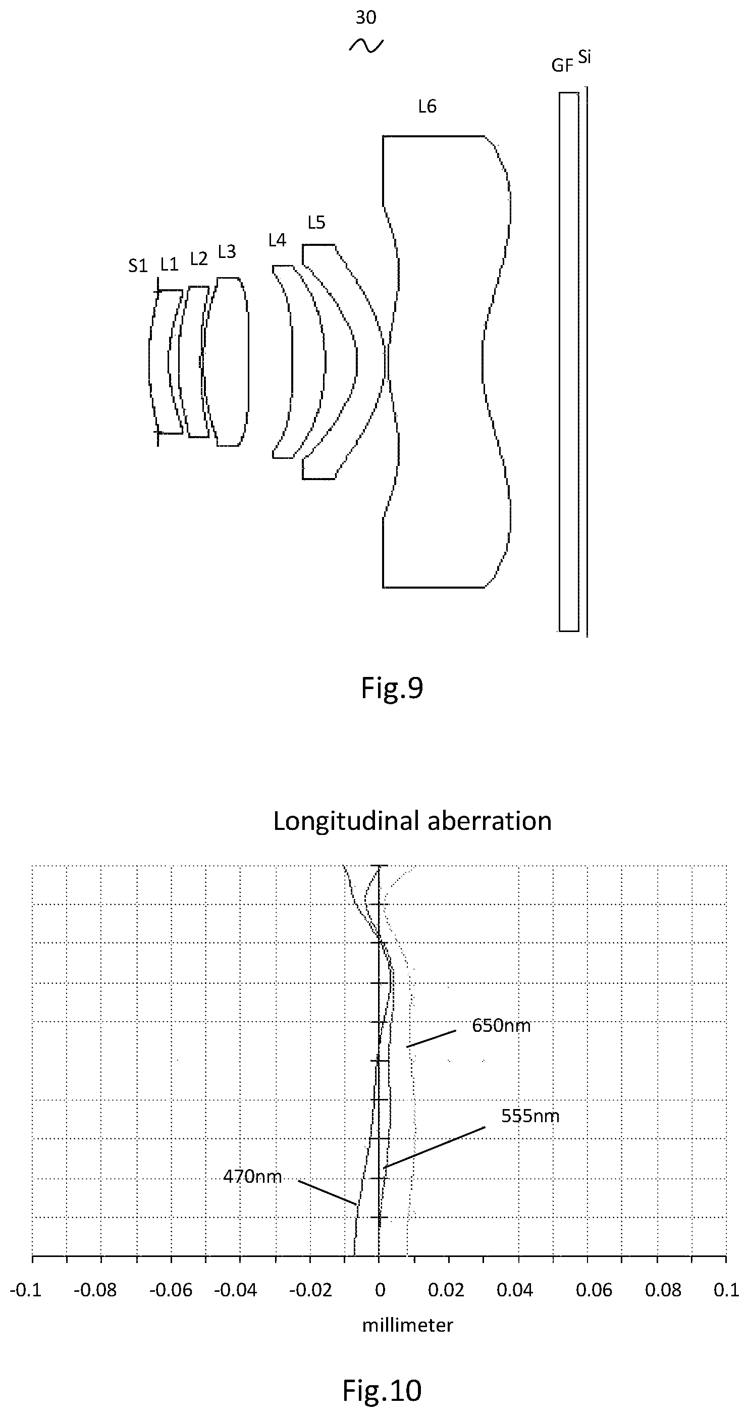
FIG. 9 is a schematic diagram of a camera optical lens in accordance with a third embodiment of the present invention;
FIG. 10 presents the longitudinal aberration of the camera optical lens shown in FIG. 9;
FIG. 11 presents the lateral color of the camera optical lens shown in FIG. 9;
FIG. 12 presents the field curvature and distortion of the camera optical lens shown in FIG. 9.
DETAILED DESCRIPTION OF THE EXEMPLARY EMBODIMENTS
The present disclosure will hereinafter be described in detail with reference to several exemplary embodiments. To make the technical problems to be solved, technical solutions and beneficial effects of the present disclosure more apparent, the present disclosure is described in further detail together with the figure and the embodiments. It should be understood the specific embodiments described hereby is only to explain the disclosure, not intended to limit the disclosure.
Embodiment 1
As referring to FIG. 1, the present invention provides a camera optical lens 10. FIG. 1 shows the camera optical lens 10 of embodiment 1 of the present invention, the camera optical lens 10 comprises six lenses. Specifically, from the object side to the image side, the camera optical lens 10 comprises in sequence: an aperture S1, a first lens L1, a second lens L2, a third lens L3, a fourth lens L4, a fifth lens L5, and a sixth lens L6. Optical element like optical filter GF can be arranged between the sixth lens L6 and the image surface Si. The first lens L1 is made of plastic material, the second lens L2 is made of glass material, the third lens L3 is made of plastic material, the fourth lens L4 is made of plastic material, the fifth lens L5 is made of glass material, and the sixth lens L6 is made of plastic material.
The second lens L2 has a positive refractive power, and the third lens L3 has a positive refractive power.
Here, the focal length of the whole camera optical lens 10 is defined as f, the focal length of the first lens is defined as f1. The camera optical lens 10 further satisfies the following condition: -3.ltoreq.f1/f.ltoreq.-1. Condition -3.ltoreq.f1/f.ltoreq.-1 fixes the negative refractive power of the first lens L1. If the upper limit of the set value is exceeded, although it benefits the ultra-thin development of lenses, but the negative refractive power of the first lens L1 will be too strong, problem like aberration is difficult to be corrected, and it is also unfavorable for wide-angle development of lens. On the contrary, if the lower limit of the set value is exceeded, the negative refractive power of the first lens L 1 becomes too weak, it is then difficult to develop ultra-thin lenses. Preferably, the following condition shall be satisfied, -2.749.ltoreq.f1/f.ltoreq.-1.261.
The refractive index of the second lens L2 is defined as n2. Here the following condition should be satisfied: 1.7.ltoreq.n2.ltoreq.2.2. This condition fixes the refractive index of the second lens L2, and refractive index within this range benefits the ultra-thin development of lenses, and it also benefits the correction of aberration. Preferably, the following condition shall be satisfied, 1.71.ltoreq.n2.ltoreq.2.052.
The refractive index of the fifth lens L5 is defined as n5. Here the following condition should be satisfied: 1.7.ltoreq.n5.ltoreq.2.2. This condition fixes the refractive index of the fifth lens L5, and refractive index within this range benefits the ultra-thin development of lenses, and it also benefits the correction of aberration. Preferably, the following condition shall be satisfied, 1.709.ltoreq.n5.ltoreq.2.062.
The thickness on-axis of the second lens L2 is defined as d3, the total distance from the object side surface of the first lens L1 to the image plane along the optic axis is defined as TTL. Here the following condition should be satisfied: 0.03.ltoreq.d3/TTL.ltoreq.0.058. This condition fixes the ratio between the thickness on-axis of the second lens L2 and total optical length TTL of the camera optical lens 10, a ratio within this range can benefits for realization of the ultra-thin lens. Preferably, the condition 0.041.ltoreq.d3/TTL.ltoreq.0.058 shall be satisfied.
When the focal length of the camera optical lens 10 of the present invention, the focal length of each lens, the refractive power of the related lens, and the total optical length, the thickness on-axis and the curvature radius of the camera optical lens satisfy the above conditions, the camera optical lens 10 has the advantage of high performance and satisfies the design requirement of low TTL.
In this embodiment, the first lens L1 has a negative refractive power with a convex object side surface relative to the proximal axis and a concave image side surface relative to the proximal axis.
The curvature radius of the object side surface of the first lens L1 is defined as R1, the curvature radius of the image side surface of the first lens L1 is defined as R2. The camera optical lens 10 further satisfies the following condition: 2.27.ltoreq.(R1+R2)/(R1-R2).ltoreq.8.61, by which, the shape of the first lens L1 can be reasonably controlled and it is effectively for correcting spherical aberration of the camera optical lens. Preferably, the condition 3.63.ltoreq.(R1+R2)/(R1-R2).ltoreq.6.89 shall be satisfied.
The thickness on-axis of the first lens L1 is defined as d1. The following condition: 0.02.ltoreq.d1/TTL.ltoreq.0.07 should be satisfied. When the condition is satisfied, it is beneficial for realization of the ultra-thin lens. Preferably, the condition 0.03.ltoreq.d1/TTL.ltoreq.0.05 shall be satisfied.
In this embodiment, the second lens L2 has a convex object side surface relative to the proximal axis and a concave image side surface relative to the proximal axis.
The focal length of the whole camera optical lens 10 is f, the focal length of the second lens L2 is f2. The following condition should be satisfied: 0.58.ltoreq.f2/f.ltoreq.2.31. The positive refractive power of the second lens L2 within this range can be reasonably controlled, which can properly and effectively balance the field curvature of the system and the spherical aberration caused by the negative refractive power of the first lens L1. Preferably, the condition 0.93.ltoreq.f2/f.ltoreq.1.85 should be satisfied.
The curvature radius of the object side surface of the second lens L2 is defined as R3, the curvature radius of the image side surface of the second lens L2 is defined as R4. The following condition should be satisfied: -6.67.ltoreq.(R3+R4)/(R3-R4).ltoreq.-1.68, which fixes the shape of the second lens L2 and when beyond this range, with the development into the direction of ultra-thin and wide-angle lenses, problem like chromatic aberration of the on-axis is difficult to be corrected. Preferably, the following condition shall be satisfied, -4.17.ltoreq.(R3+R4)/(R3-R4).ltoreq.-2.10.
The thickness on-axis of the second lens L2 is defined as d3. The following condition: 0.03.ltoreq.d3/TTL.ltoreq.0.09 should be satisfied. When the condition is satisfied, it is beneficial for realization of the ultra-thin lens. Preferably, the condition 0.04.ltoreq.d3/TTL.ltoreq.0.07 shall be satisfied.
In this embodiment, the third lens L3 has a convex object side surface relative to the proximal axis.
The focal length of the whole camera optical lens 10 is f, the focal length of the third lens L3 is f3. The following condition should be satisfied: 0.62.ltoreq.f3/f.ltoreq.2.07. When the condition is satisfied, it is beneficial for the system to balance field curvature and further enhance the imaging quality. Preferably, the condition 0.99.ltoreq.f3/f.ltoreq.1.66 should be satisfied.
The curvature radius of the object side surface of the third lens L3 is defined as R5, the curvature radius of the image side surface of the third lens L3 is defined as R6. The following condition should be satisfied: -2.19.ltoreq.(R5+R6)/(R5-R6).ltoreq.-0.51, by which, the shape of the third lens L3 can be effectively controlled and it is beneficial for shaping of the third lens L3, further, it also can avoid bad molding and stress caused by the excessive curvature of the third lens L3. Preferably, the following condition shall be satisfied, -1.37.ltoreq.(R5+R5)/(R5-R6).ltoreq.-0.64.
The thickness on-axis of the third lens L3 is defined as d5. The following condition: 0.05.ltoreq.d5/TTL.ltoreq.0.16 should be satisfied. When the condition is satisfied, it is beneficial for realization of the ultra-thin lens. Preferably, the condition 0.08.ltoreq.d5/TTL.ltoreq.0.12 shall be satisfied.
In this embodiment, the fourth lens L4 has a positive refractive power with a concave object side surface relative to the proximal axis and a convex image side surface relative to the proximal axis.
The focal length of the whole camera optical lens 10 is f, the focal length of the fourth lens L4 is f4. The following condition should be satisfied: 0.79.ltoreq.f4/f.ltoreq.2.60, the appropriate distribution of refractive power makes it possible that the system has better imaging quality and lower sensitivity. Preferably, the condition 1.26.ltoreq.f4/f.ltoreq.2.08 should be satisfied.
The curvature radius of the object side surface of the fourth lens L4 is defined as R7, the curvature radius of the image side surface of the fourth lens L4 is defined as R8. The following condition should be satisfied: 0.87.ltoreq.(R7+R8)/(R7-R8).ltoreq.2.95, by which, the shape of the fourth lens L4 is fixed, further, when beyond this range, with the development into the direction of ultra-thin and wide-angle lenses, problem like aberration of the off-axis picture angle is difficult to be corrected. Preferably, the following condition shall be satisfied, 1.39.ltoreq.(R7+R8)/(R7-R8).ltoreq.2.36.
The thickness on-axis of the fourth lens L4 is defined as d7. The following condition: 0.04.ltoreq.d7/TTL.ltoreq.0.14 should be satisfied. When the condition is satisfied, it is beneficial for realization of the ultra-thin lens. Preferably, the condition 0.06.ltoreq.d7/TTL.ltoreq.0.11 shall be satisfied.
In this embodiment, the fifth lens L5 has a negative refractive power with a concave object side surface relative to the proximal axis and a convex image side surface relative to the proximal axis.
The focal length of the whole camera optical lens 10 is f, the focal length of the fifth lens L5 is f5. The following condition should be satisfied: -2.65.ltoreq.f5/f.ltoreq.-0.75, which can effectively smooth the light angles of the camera and reduce the tolerance sensitivity. Preferably, the condition -1.66.ltoreq.f5/f.ltoreq.-0.94 should be satisfied.
The curvature radius of the object side surface of the fifth lens L5 is defined as R9, the curvature radius of the image side surface of the fifth lens L5 is defined as R10. The following condition should be satisfied: -11.94.ltoreq.(R9+R10)/(R9-R10).ltoreq.-3.37, by which, the shape of the fifth lens L5 is fixed, further, when beyond this range, with the development into the direction of ultra-thin and wide-angle lenses, problem like aberration of the off-axis picture angle is difficult to be corrected. Preferably, the following condition shall be satisfied, -7.46.ltoreq.(R9+R10)/(R9-R10).ltoreq.-4.22.
The thickness on-axis of the fifth lens L5 is defined as d9. The following condition: 0.02.ltoreq.d9/TTL.ltoreq.0.09 should be satisfied. When the condition is satisfied, it is beneficial for realization of the ultra-thin lens. Preferably, the condition 0.04.ltoreq.d9/TTL.ltoreq.0.08 shall be satisfied.
In this embodiment, the sixth lens L6 has a positive refractive power with a convex object side surface relative to the proximal axis and a concave image side surface relative to the proximal axis.
The focal length of the whole camera optical lens 10 is f, the focal length of the sixth lens L6 is f6. The following condition should be satisfied: 1.49.ltoreq.f6/f.ltoreq.5.79, the appropriate distribution of refractive power makes it possible that the system has better imaging quality and lower sensitivity. Preferably, the condition 2.39.ltoreq.f6/f.ltoreq.4.63 should be satisfied.
The curvature radius of the object side surface of the sixth lens L6 is defined as R11, the curvature radius of the image side surface of the sixth lens L6 is defined as R12. The following condition should be satisfied: -75.69.ltoreq.(R11+R12)/(R11-R12).ltoreq.1439.02, by which, the shape of the sixth lens L6 is fixed, further, when beyond this range, with the development into the direction of ultra-thin and wide-angle lenses, problem like aberration of the off-axis picture angle is difficult to be corrected. Preferably, the following condition shall be satisfied, -47.48.ltoreq.(R11+R12)/(R11-R12).ltoreq.1151.22.
The thickness on-axis of the sixth lens L6 is defined as d11. The following condition: 0.10.ltoreq.d11/TTL.ltoreq.0.32 should be satisfied. When the condition is satisfied, it is beneficial for realization of the ultra-thin lens. Preferably, the condition 0.16.ltoreq.d11/TTL.ltoreq.0.26 shall be satisfied.
The focal length of the whole camera optical lens 10 is f, the combined focal length of the first lens L1 and the second lens L2 is f12. The following condition should be satisfied: 2.30.ltoreq.f12/f.ltoreq.9.90, which can effectively avoid the aberration and field curvature of the camera optical lens, suppress the rear focal length for realizing the ultra-thin lens, and maintain the miniaturization of lens system. Preferably, the condition 3.69.ltoreq.f12/f.ltoreq.7.92 should be satisfied.
In this embodiment, the total optical length TTL of the camera optical lens 10 is less than or equal to 5.17 mm, it is beneficial for the realization of ultra-thin lenses. Preferably, the total optical length TTL of the camera optical lens 10 is less than or equal to 4.94 mm.
In this embodiment, the camera optical lens 10 is large aperture and the aperture F number of the camera optical lens 10 is less than or equal to 2.27. A large aperture has better imaging performance. Preferably, the aperture F number of the camera optical lens 10 is less than or equal to 2.22.
With such design, the total optical length TTL of the whole camera optical lens 10 can be made as short as possible, thus the miniaturization characteristics can be maintained.
In the following, an example will be used to describe the camera optical lens 10 of the present invention. The symbols recorded in each example are as follows. The unit of distance, radius and center thickness is mm.
TTL: Optical length (the distance on-axis from the object side surface of the first lens L1 to the image surface).
Preferably, inflexion points and/or arrest points can also be arranged on the object side surface and/or image side surface of the lens, so that the demand for high quality imaging can be satisfied, the description below can be referred for specific implementable scheme.
The design information of the camera optical lens 10 in the first embodiment of the present invention is shown in the following, the unit of the focal length, distance, radius and center thickness is mm.
The design information of the camera optical lens 10 in the first embodiment of the present invention is shown in the tables 1 and 2.
TABLE-US-00001 TABLE 1 R d nd .nu.d S1 .infin. d0 = -0.100 R1 1.798 d1 = 0.205 nd1 1.671 .nu.1 19.24 R2 1.148 d2 = 0.059 R3 1.777 d3 = 0.272 nd2 1.721 .nu.2 34.71 R4 4.112 d4 = 0.030 R5 2.282 d5 = 0.456 nd3 1.545 .nu.3 55.99 R6 51.438 d6 = 0.564 R7 -7.482 d7 = 0.442 nd4 1.535 .nu.4 56.09 R8 -2.255 d8 = 0.365 R9 -0.649 d9 = 0.213 nd5 1.717 .nu.5 29.52 R10 -0.954 d10 = 0.030 R11 1.472 d11 = 0.932 nd6 1.535 .nu.6 56.09 R12 1.469 d12 = 0.821 R13 .infin. d13 = 0.210 ndg 1.517 .nu.g 64.17 R14 .infin. d14 = 0.100
Where:
In which, the meaning of the various symbols is as follows.
S1: Aperture;
R: The curvature radius of the optical surface, the central curvature radius in case of lens;
R1: The curvature radius of the object side surface of the first lens L1;
R2: The curvature radius of the image side surface of the first lens L1;
R3: The curvature radius of the object side surface of the second lens L2;
R4: The curvature radius of the image side surface of the second lens L2;
R5: The curvature radius of the object side surface of the third lens L3;
R6: The curvature radius of the image side surface of the third lens L3;
R7: The curvature radius of the object side surface of the fourth lens L4;
R8: The curvature radius of the image side surface of the fourth lens L4;
R9: The curvature radius of the object side surface of the fifth lens L5;
R10: The curvature radius of the image side surface of the fifth lens L5;
R11: The curvature radius of the object side surface of the sixth lens L6;
R12: The curvature radius of the image side surface of the sixth lens L6;
R13: The curvature radius of the object side surface of the optical filter GF;
R14: The curvature radius of the image side surface of the optical filter GF;
d: The thickness on-axis of the lens and the distance on-axis between the lens;
d0: The distance on-axis from aperture S1 to the object side surface of the first lens L1;
d1: The thickness on-axis of the first lens L1;
d2: The distance on-axis from the image side surface of the first lens L1 to the object side surface of the second lens L2;
d3: The thickness on-axis of the second lens L2;
d4: The distance on-axis from the image side surface of the second lens L2 to the object side surface of the third lens L3;
d5: The thickness on-axis of the third lens L3;
d6: The distance on-axis from the image side surface of the third lens L3 to the object side surface of the fourth lens L4;
d7: The thickness on-axis of the fourth lens L4;
d8: The distance on-axis from the image side surface of the fourth lens L4 to the object side surface of the fifth lens L5;
d9: The thickness on-axis of the fifth lens L5;
d10: The distance on-axis from the image side surface of the fifth lens L5 to the object side surface of the sixth lens L6;
d11: The thickness on-axis of the sixth lens L6;
d12: The distance on-axis from the image side surface of the sixth lens L6 to the object side surface of the optical filter GF;
d13: The thickness on-axis of the optical filter GF;
d14: The distance on-axis from the image side surface to the image surface of the optical filter GF;
nd: The refractive index of the d line;
nd1: The refractive index of the d line of the first lens L1;
nd2: The refractive index of the d line of the second lens L2;
nd3: The refractive index of the d line of the third lens L3;
nd4: The refractive index of the d line of the fourth lens L4;
nd5: The refractive index of the d line of the fifth lens L5;
nd6: The refractive index of the d line of the sixth lens L6;
ndg: The refractive index of the d line of the optical filter GF;
vd: The abbe number;
v1: The abbe number of the first lens L1;
v2: The abbe number of the second lens L2;
v3: The abbe number of the third lens L3;
v4: The abbe number of the fourth lens L4;
v5: The abbe number of the fifth lens L5;
v6: The abbe number of the sixth lens L6;
vg: The abbe number of the optical filter GF.
Table 2 shows the aspherical surface data of the camera optical lens 10 in the embodiment 1 of the present invention.
TABLE-US-00002 TABLE 2 Conic Index Aspherical Surface Index k A4 A6 A8 A10 A12 A14 A16 R1 -4.7173E+00 -1.7645E-01 2.2119E-01 -1.5105E-01 -2.1451E-02 1.1127E-01 1- .3762E-01 -1.9456E-01 R2 -3.1660E+00 -1.8717E-01 2.1969E-01 -5.2952E-02 -3.1274E-01 1.7289E-01 6- .6484E-01 -6.0512E-01 R3 2.4032E+00 -1.1914E-01 1.1825E-01 -1.7649E-01 -8.4796E-02 -8.7722E-03 -6.5060E-02 2.3159E-02 R4 -1.1106E+02 1.7117E-01 3.0121E-02 4.5702E-02 -6.9650E-03 -3.2272E-01 -3.1706E-01 5.5084E-01 R5 1.7308E+00 -1.0127E-01 2.5775E-01 -2.7360E-01 -5.7635E-02 1.0594E-01 2- .0620E-01 -3.1589E-01 R6 1.2000E+02 -9.3839E-02 -1.9933E-02 -5.9439E-02 -4.9561E-02 1.0058E-01 7.4811E-02 -1.7321E-01 R7 -9.9042E+01 -1.2218E-01 -1.5502E-02 -1.1672E-02 -6.0766E-02 3.2468E-02 6.8803E-02 -4.7338E-02 R8 2.8729E+00 -6.8843E-02 1.6015E-02 -4.0383E-03 -1.4223E-02 1.6505E-02 1- .8757E-02 -2.7364E-03 R9 -3.1929E+00 -1.1430E-01 -2.1045E-02 -1.8405E-02 1.1570E-02 1.0048E-02 -1.7486E-03 -2.9274E-03 R10 -3.5118E+00 -2.2103E-02 -1.7041E-02 6.9400E-03 3.2361E-03 1.3588E-03 6.3065E-04 -3.1203E-04 R11 -1.1941E+01 -1.0459E-01 1.6576E-02 6.3614E-04 1.6243E-05 -2.4800E-05 -1.6377E-05 2.7928E-06 R12 -4.8043E+00 -5.2820E-02 1.1792E-02 -1.8918E-03 1.2548E-04 4.8514E-07 -6.2244E-07 2.0243E-08
Among them, K is a conic index, A4, A6, A8, A10, A12, A14, A16 are aspheric surface indexes.
IH: Image height y=(x.sup.2/R)/[1+{1-(k+1)(x.sup.2/R.sup.2)}.sup.1/2]+A4x.sup.4+A6x.sup.6+- A8x.sup.8+A10x.sup.10A12x.sup.12+A14x.sup.14+A16x.sup.16 (1)
For convenience, the aspheric surface of each lens surface uses the aspheric surfaces shown in the above condition (1). However, the present invention is not limited to the aspherical polynomials form shown in the condition (1).
Table 3 and table 4 show the inflexion points and the arrest point design data of the camera optical lens 10 lens in embodiment 1 of the present invention. In which, P1R1 and P1R2 represent respectively the object side surface and image side surface of the first lens L1, P2R1 and P2R2 represent respectively the object side surface and image side surface of the second lens L2, P3R1 and P3R2 represent respectively the object side surface and image side surface of the third lens L3, P4R1 and P4R2 represent respectively the object side surface and image side surface of the fourth lens L4, P5R1 and P5R2 represent respectively the object side surface and image side surface of the fifth lens L5, P6R1 and P6R2 represent respectively the object side surface and image side surface of the sixth lens L6. The data in the column named "inflexion point position" are the vertical distances from the inflexion points arranged on each lens surface to the optic axis of the camera optical lens 10. The data in the column named "arrest point position" are the vertical distances from the arrest points arranged on each lens surface to the optic axis of the camera optical lens 10.
TABLE-US-00003 TABLE 3 Inflexion point Inflexion point Inflexion point number position 1 position 2 P1R1 0 P1R2 0 P2R1 1 0.725 P2R2 1 0.755 P3R1 1 0.745 P3R2 1 0.135 P4R1 0 P4R2 0 P5R1 0 P5R2 1 1.005 P6R1 2 0.455 1.605 P6R2 1 0.735
TABLE-US-00004 TABLE 4 Arrest point number Arrest point position 1 P1R1 0 P1R2 0 P2R1 0 P2R2 0 P3R1 0 P3R2 1 0.225 P4R1 0 P4R2 0 P5R1 0 P5R2 0 P6R1 1 0.945 P6R2 1 1.635
FIG. 2 and FIG. 3 show the longitudinal aberration and lateral color schematic diagrams after light with a wavelength of 470 nm, 555 nm and 650 nm passes the camera optical lens 10 in the first embodiment. FIG. 4 shows the field curvature and distortion schematic diagrams after light with a wavelength of 555 nm passes the camera optical lens 10 in the first embodiment, the field curvature S in FIG. 4 is a field curvature in the sagittal direction, T is a field curvature in the meridian direction.
Table 13 shows the various values of the embodiments 1, 2, 3, and the values corresponding with the parameters which are already specified in the conditions.
As shown in Table 13, the first embodiment satisfies the various conditions.
In this embodiment, the pupil entering diameter of the camera optical lens is 1.606 mm, the full vision field image height is 2.933 mm, the vision field angle in the diagonal direction is 78.42.degree., it has wide-angle and is ultra-thin, its on-axis and off-axis chromatic aberrations are fully corrected, and it has excellent optical characteristics.
Embodiment 2
Embodiment 2 is basically the same as embodiment 1, the meaning of its symbols is the same as that of embodiment 1, in the following, only the differences are described.
Table 5 and table 6 show the design data of the camera optical lens 20 in embodiment 2 of the present invention.
TABLE-US-00005 TABLE 5 R d nd .nu.d S1 .infin. d0 = -0.110 R1 1.837 d1 = 0.215 nd1 1.671 .nu.1 19.24 R2 1.256 d2 = 0.097 R3 2.099 d3 = 0.255 nd2 1.801 .nu.2 34.97 R4 4.369 d4 = 0.045 R5 2.578 d5 = 0.462 nd3 1.545 .nu.3 55.99 R6 -138.670 d6 = 0.505 R7 -6.738 d7 = 0.397 nd4 1.535 .nu.4 56.09 R8 -2.196 d8 = 0.401 R9 -0.668 d9 = 0.219 nd5 1.808 .nu.5 22.76 R10 -0.936 d10 = 0.030 R11 1.504 d11 = 0.949 nd6 1.535 .nu.6 56.09 R12 1.492 d12 = 0.817 R13 .infin. d13 = 0.210 ndg 1.517 .nu.g 64.17 R14 .infin. d14 = 0.100
Table 6 shows the aspherical surface data of each lens of the camera optical lens 20 in embodiment 2 of the present invention.
TABLE-US-00006 TABLE 6 Conic Index Aspherical Surface Index k A4 A6 A8 A10 A12 A14 A16 R1 -2.4954E+00 -1.5332E-01 1.8060E-01 -2.1000E-01 1.4204E-01 8.0637E-02 -1.1606E-01 1.8266E-02 R2 -2.6263E+00 -1.6135E-01 2.0331E-01 -3.6327E-02 -3.2664E-01 1.1556E-01 6- .2924E-01 -4.6286E-01 R3 3.3031E+00 -1.3255E-01 1.8785E-01 -2.2341E-01 -7.4502E-02 -1.1134E-02 -1.2555E-01 2.4129E-01 R4 -1.2028E+02 1.3283E-01 4.0999E-02 9.5824E-02 -2.7686E-01 -2.7193E-01 3.1437E-01 1.2070E-01 R5 5.5826E+00 -8.3282E-02 2.4249E-01 -3.2756E-01 -5.5633E-02 1.1223E-01 1- .0231E-01 -1.9937E-01 R6 0.0000E+00 -9.2920E-02 -2.6047E-02 -4.5329E-02 -1.0538E-02 3.7380E-03 8.4016E-02 -1.2095E-01 R7 -3.0750E+01 -1.2682E-01 -5.0458E-02 -3.3313E-02 -2.2690E-02 4.9192E-02 5.0959E-02 -2.2659E-02 R8 2.4506E+00 -6.7038E-02 1.0273E-02 -1.9604E-02 -1.6683E-02 2.9501E-02 3- .0965E-02 -1.1991E-02 R9 -3.1064E+00 -8.4112E-02 -9.5331E-03 -2.0915E-02 1.0548E-02 1.2964E-02 -2.6810E-04 -7.1602E-03 R10 -2.9825E+00 -2.1614E-02 -1.2648E-02 7.4155E-03 2.4645E-03 1.1107E-03 8.4395E-04 -7.0657E-05 R11 -1.1750E+01 -1.1638E-01 1.8144E-02 9.6839E-04 1.1979E-04 -2.2866E-05 -2.6954E-05 3.3690E-06 R12 -4.5808E+00 -5.5850E-02 1.2784E-02 -2.1394E-03 1.5060E-04 1.3043E-06 -9.1766E-07 2.0690E-08
Table 7 and table 8 show the inflexion points and the arrest point design data of the camera optical lens 20 lens in embodiment 2 of the present invention.
TABLE-US-00007 TABLE 7 Inflexion point number Inflexion point position 1 Inflexion point position 2 P1R1 0 P1R2 0 P2R1 2 0.705 0.825 P2R2 0 P3R1 1 0.735 P3R2 0 P4R1 1 0.925 P4R2 1 0.985 P5R1 0 P5R2 1 0.985 P6R1 2 0.445 1.525 P6R2 1 0.735
TABLE-US-00008 TABLE 8 Arrest point number Arrest point position 1 P1R1 0 P1R2 0 P2R1 0 P2R2 0 P3R1 0 P3R2 0 P4R1 0 P4R2 0 P5R1 0 P5R2 0 P6R1 1 0.905 P6R2 1 1.605
FIG. 6 and FIG. 7 show the longitudinal aberration and lateral color schematic diagrams after light with a wavelength of 470 nm, 555 nm and 650 nm passes the camera optical lens 20 in the second embodiment. FIG. 8 shows the field curvature and distortion schematic diagrams after light with a wavelength of 555 nm passes the camera optical lens 20 in the second embodiment.
As shown in Table 13, the second embodiment satisfies the various conditions.
In this embodiment, the pupil entering diameter of the camera optical lens is 1.698 mm, the full vision field image height is 2.933 mm, the vision field angle in the diagonal direction is 81.46.degree., it has wide-angle and is ultra-thin, its on-axis and off-axis chromatic aberrations are fully corrected, and it has excellent optical characteristics.
Embodiment 3
Embodiment 3 is basically the same as embodiment 1, the meaning of its symbols is the same as that of embodiment 1, in the following, only the differences are described.
Table 9 and table 10 show the design data of the camera optical lens 30 in embodiment 3 of the present invention.
TABLE-US-00009 TABLE 9 R d nd .nu.d S1 .infin. d0 = -0.100 R1 2.023 d1 = 0.215 nd1 1.671 .nu.1 19.24 R2 1.423 d2 = 0.101 R3 2.266 d3 = 0.240 nd2 1.903 .nu.2 31.01 R4 4.206 d4 = 0.033 R5 2.816 d5 = 0.487 nd3 1.545 .nu.3 55.99 R6 -20.938 d6 = 0.465 R7 -7.824 d7 = 0.347 nd4 1.535 .nu.4 56.09 R8 -2.096 d8 = 0.351 R9 -0.686 d9 = 0.295 nd5 1.923 .nu.5 18.90 R10 -1.025 d10 = 0.030 R11 1.474 d11 = 1.006 nd6 1.535 .nu.6 56.09 R12 1.553 d12 = 0.822 R13 .infin. d13 = 0.210 ndg 1.517 .nu.g 64.17 R14 .infin. d14 = 0.100
Table 10 shows the aspherical surface data of each lens of the camera optical lens 30 in embodiment 3 of the present invention.
TABLE-US-00010 TABLE 10 Conic Index Aspherical Surface Index k A4 A6 A8 A10 A12 A14 A16 R1 -1.1966E+00 -1.4228E-01 1.2867E-01 -2.1112E-01 2.1982E-01 5.9718E-02 -2.0014E-01 3.9414E-02 R2 -1.7821E+00 -1.4911E-01 1.3141E-01 -5.2365E-02 -2.8772E-01 1.8598E-01 3- .7300E-01 -6.6595E-01 R3 4.3417E+00 -8.7969E-02 8.3778E-02 -1.7886E-01 -7.7747E-02 -1.2165E-01 -2.4391E-01 1.6130E-01 R4 -7.5968E+01 1.3878E-01 5.5413E-02 -2.6625E-02 -3.2453E-01 -2.3781E-01 4.9210E-01 5.4100E-02 R5 7.0634E+00 -1.3818E-02 2.2020E-01 -4.1546E-01 -3.4964E-02 2.2054E-01 1- .1215E-01 -2.4347E-01 R6 0.0000E+00 -8.0097E-02 -4.2115E-02 -4.4224E-02 1.0823E-02 -1.1110E-02 2.5705E-02 -6.3914E-02 R7 2.5639E+00 -1.3053E-01 -4.2653E-02 -3.9598E-02 -2.7959E-02 3.9075E-02 2.4321E-02 4.9439E-03 R8 2.3229E+00 -4.8227E-02 2.0414E-02 -2.1248E-02 -1.4413E-02 3.5179E-02 3- .9298E-02 -1.6195E-02 R9 -3.1114E+00 -9.2033E-02 -4.2227E-03 -2.1585E-02 1.0687E-02 1.6789E-02 2.7324E-04 -7.8764E-03 R10 -3.0347E+00 -3.1786E-02 -1.5771E-02 7.3989E-03 2.5410E-03 9.7056E-04 8.8625E-04 3.8161E-05 R11 -9.2810E+00 -1.1522E-01 1.7309E-02 8.4515E-04 1.1419E-04 -1.8072E-05 -2.5452E-05 3.2960E-06 R12 -4.1790E+00 -5.7827E-02 1.3844E-02 -2.3312E-03 1.7349E-04 1.1926E-07 -9.6543E-07 3.3004E-08
Table 11 and table 12 show the inflexion points and the arrest point design data of the camera optical lens 30 lens in embodiment 3 of the present invention.
TABLE-US-00011 TABLE 11 Inflexion point Inflexion number point position 1 Inflexion point position 2 P1R1 0 P1R2 1 0.615 P2R1 1 0.615 P2R2 1 0.675 P3R1 1 0.765 P3R2 0 P4R1 1 0.955 P4R2 1 0.935 P5R1 0 P5R2 1 1.025 P6R1 2 0.475 1.565 P6R2 1 0.755
TABLE-US-00012 TABLE 12 Arrest point number Arrest point position 1 P1R1 0 P1R2 0 P2R1 0 P2R2 0 P3R1 0 P3R2 0 P4R1 0 P4R2 0 P5R1 0 P5R2 0 P6R1 1 0.945 P6R2 1 1.655
FIG. 10 and FIG. 11 show the longitudinal aberration and lateral color schematic diagrams after light with a wavelength of 470 nm, 555 nm and 650 nm passes the camera optical lens 30 in the third embodiment. FIG. 12 shows the field curvature and distortion schematic diagrams after light with a wavelength of 555 nm passes the camera optical lens 30 in the third embodiment.
As shown in Table 13, the third embodiment satisfies the various conditions.
In this embodiment, the pupil entering diameter of the camera optical lens is 1.505 mm, the full vision field image height is 2.933 mm, the vision field angle in the diagonal direction is 83.02.degree., it has wide-angle and is ultra-thin, its on-axis and off-axis chromatic aberrations are fully corrected, and it has excellent optical characteristics.
TABLE-US-00013 TABLE 13 Embodiment 1 Embodiment2 Embodiment 3 f 3.534 3.396 3.312 f1 -5.373 -6.897 -8.273 f2 4.120 4.780 5.110 f3 4.358 4.638 4.576 f4 5.839 5.886 5.220 f5 -3.975 -4.504 -3.848 f6 12.487 13.099 9.888 f12 23.322 18.706 15.262 (R1 + R2)/(R1 - R2) 4.533 5.327 5.741 (R3 + R4)/(R3 - R4) -2.523 -2.850 -3.336 (R5 + R6)/(R5 - R6) -1.093 -0.964 -0.763 (R7 + R8)/(R7 - R8) 1.863 1.967 1.732 (R9 + R10)/ -5.251 -5.970 -5.058 (R9 - R10) (R11 + R12)/ 959.348 241.875 -37.982 (R11 - R12) f1/f -1.521 -2.031 -2.498 f2/f 1.166 1.408 1.543 f3/f 1.233 1.366 1.382 f4/f 1.653 1.733 1.576 f5/f -1.125 -1.326 -1.162 f6/f 3.534 3.857 2.986 f12/f 6.600 5.509 4.609 d1 0.205 0.215 0.215 d3 0.272 0.255 0.240 d5 0.456 0.462 0.487 d7 0.442 0.397 0.347 d9 0.213 0.219 0.295 d11 0.932 0.949 1.006 Fno 2.200 2.000 2.200 TTL 4.700 4.701 4.700 d1/TTL 0.044 0.046 0.046 d3/TTL 0.058 0.054 0.051 d5/TTL 0.097 0.098 0.104 d7/TTL 0.094 0.084 0.074 d9/TTL 0.045 0.047 0.063 d11/TTL 0.198 0.202 0.214 n1 1.671 1.671 1.671 n2 1.721 1.8010 1.903 n3 1.545 1.545 1.545 n4 1.535 1.535 1.535 n5 1.717 1.808 1.923 n6 1.535 1.535 1.535 v1 19.243 19.243 19.243 v2 34.708 34.967 31.005 v3 55.987 55.987 55.987 v4 56.093 56.093 56.093 v5 29.518 22.761 18.897 v6 56.093 56.093 56.093
It is to be understood, however, that even though numerous characteristics and advantages of the present exemplary embodiments have been set forth in the foregoing description, together with details of the structures and functions of the embodiments, the disclosure is illustrative only, and changes may be made in detail, especially in matters of shape, size, and arrangement of parts within the principles of the invention to the full extent indicated by the broad general meaning of the terms where the appended claims are expressed.
* * * * *
D00000
D00001
D00002
D00003
D00004
D00005
D00006
D00007
XML
uspto.report is an independent third-party trademark research tool that is not affiliated, endorsed, or sponsored by the United States Patent and Trademark Office (USPTO) or any other governmental organization. The information provided by uspto.report is based on publicly available data at the time of writing and is intended for informational purposes only.
While we strive to provide accurate and up-to-date information, we do not guarantee the accuracy, completeness, reliability, or suitability of the information displayed on this site. The use of this site is at your own risk. Any reliance you place on such information is therefore strictly at your own risk.
All official trademark data, including owner information, should be verified by visiting the official USPTO website at www.uspto.gov. This site is not intended to replace professional legal advice and should not be used as a substitute for consulting with a legal professional who is knowledgeable about trademark law.