Camera Optical Lens
Teranishi; Takaaki ; et al.
U.S. patent application number 16/531142 was filed with the patent office on 2020-02-20 for camera optical lens. The applicant listed for this patent is AAC Technologies Pte. Ltd.. Invention is credited to Wenbo Hu, Takaaki Teranishi, Yanmei Wang, Lei Zhang.
| Application Number | 20200057278 16/531142 |
| Document ID | / |
| Family ID | 67473251 |
| Filed Date | 2020-02-20 |


| United States Patent Application | 20200057278 |
| Kind Code | A1 |
| Teranishi; Takaaki ; et al. | February 20, 2020 |
Camera Optical Lens
Abstract
The present disclosure discloses a camera optical lens. The camera optical lens including, in an order from an object side to an image side, a first lens, a second lens having a positive refractive power, a third lens having a positive refractive power, a fourth lens, a fifth lens, and a sixth lens. The camera optical lens further satisfies specific conditions.
| Inventors: | Teranishi; Takaaki; (Shenzhen, CN) ; Zhang; Lei; (Shenzhen, CN) ; Wang; Yanmei; (Shenzhen, CN) ; Hu; Wenbo; (Shenzhen, CN) | ||||||||||
| Applicant: |
|
||||||||||
|---|---|---|---|---|---|---|---|---|---|---|---|
| Family ID: | 67473251 | ||||||||||
| Appl. No.: | 16/531142 | ||||||||||
| Filed: | August 5, 2019 |
| Current U.S. Class: | 1/1 |
| Current CPC Class: | G02B 9/62 20130101; G02B 13/0045 20130101; G02B 1/041 20130101 |
| International Class: | G02B 13/00 20060101 G02B013/00; G02B 9/62 20060101 G02B009/62; G02B 1/04 20060101 G02B001/04 |
Foreign Application Data
| Date | Code | Application Number |
|---|---|---|
| Aug 14, 2018 | CN | 201810924592.4 |
| Aug 14, 2018 | CN | 201810925278.8 |
Claims
1. A camera optical lens comprising, from an object side to an image side in sequence: a first lens, a second lens, a third lens, a fourth lens, a fifth lens and a sixth lens; wherein the second lens has a positive refractive power, the third lens has a positive refractive power; the camera optical lens further satisfies the following conditions: -3.ltoreq.f1/f.ltoreq.-1; 1.7.ltoreq.n6.ltoreq.2.2; 0.03.ltoreq.d11/TTL.ltoreq.0.075; where f: the focal length of the camera optical lens; f1: the focal length of the first lens; n6: the refractive power of the sixth lens; d11: the thickness on-axis of the sixth lens; TTL: the total optical length of the camera optical lens.
2. The camera optical lens as described in claim 1, wherein the first lens is made of plastic material, the second lens is made of plastic material, the third lens is made of plastic material, the fourth lens is made of plastic material, the fifth lens is made of plastic material, the sixth lens is made of glass material.
3. The camera optical lens as described in claim 1, wherein the camera optical lens further satisfies the following conditions: -2.997.ltoreq.f1/f.ltoreq.-1.535; 1.701.ltoreq.n6.ltoreq.2.046; 0.0475.ltoreq.d11/TTL.ltoreq.0.0745.
4. The camera optical lens as described in claim 1, wherein the first lens has a negative refractive power with a convex object side surface and a concave image side surface; the camera optical lens further satisfies the following conditions: 1.01.ltoreq.(R1+R2)/(R1-R2).ltoreq.5.68; 0.02.ltoreq.d1/TTL.ltoreq.0.07; where R1: the curvature radius of object side surface of the first lens; R2: the curvature radius of image side surface of the first lens; d1: the thickness on-axis of the first lens; TTL: the total optical length of the camera optical lens.
5. The camera optical lens as described in claim 4, wherein the camera optical lens further satisfies the following conditions: 1.61.ltoreq.(R1+R2)/(R1-R2).ltoreq.4.55; 0.04.ltoreq.d1/TTL.ltoreq.0.05.
6. The camera optical lens as described in claim 1, wherein the second lens has a convex object side surface and a concave image side surface; the camera optical lens further satisfies the following conditions: 10.8.ltoreq.f2/f.ltoreq.275.23; 17.49.ltoreq.(R3+R4)/(R3-R4).ltoreq.89.21; 0.02.ltoreq.d3/TTL.ltoreq.0.07; where f: the focal length of the camera optical lens; f2: the focal length of the second lens; R3: the curvature radius of the object side surface of the second lens; R4: the curvature radius of the image side surface of the second lens; d3: the thickness on-axis of the second lens; TTL: the total optical length of the camera optical lens.
7. The camera optical lens as described in claim 6, wherein the camera optical lens further satisfies the following conditions: 17.28.ltoreq.f2/f.ltoreq.220.18; 27.99.ltoreq.(R3+R4)/(R3-R4).ltoreq.71.37; 0.04.ltoreq.d3/TTL.ltoreq.0.05.
8. The camera optical lens as described in claim 1, wherein the third lens has a convex object side surface and a convex image side surface; the camera optical lens further satisfies the following conditions: 0.35.ltoreq.f3/f.ltoreq.1.16; -1.57.ltoreq.(R5+R6)/(R5-R6).ltoreq.-0.51; 0.05.ltoreq.d5/TTL.ltoreq.0.17; where f: the focal length of the camera optical lens; f3: the focal length of the third lens; R5: the curvature radius of the object side surface of the third lens; R6: the curvature radius of the image side surface of the third lens; d5: the thickness on-axis of the third lens; TTL: the total optical length of the camera optical lens.
9. The camera optical lens as described in claim 8, wherein the camera optical lens further satisfies the following conditions: 0.56.ltoreq.f3/f.ltoreq.0.93; -0.98.ltoreq.(R5+R6)/(R5-R6).ltoreq.-0.64; 0.08.ltoreq.d5/TTL.ltoreq.0.14.
10. The camera optical lens as described in claim 1, wherein the fourth lens has a negative refractive power with a concave object side surface and a convex image side surface; the camera optical lens further satisfies the following conditions: -3.77.ltoreq.f4/f.ltoreq.-1.08; -5.99.ltoreq.(R7+R8)/(R7-R8).ltoreq.-1.62; 0.03.ltoreq.d7/TTL.ltoreq.0.11; where f: the focal length of the camera optical lens; f4: the focal length of the fourth lens; R7: the curvature radius of the object side surface of the fourth lens; R8: the curvature radius of the image side surface of the fourth lens; d7: the thickness on-axis of the fourth lens; TTL: the total optical length of the camera optical lens.
11. The camera optical lens as described in claim 10, wherein the camera optical lens further satisfies the following conditions: -2.36.ltoreq.f4/f.ltoreq.-1.36; -3.74.ltoreq.(R7+R8)/(R7-R8).ltoreq.-2.02; 0.04.ltoreq.d7/TTL.ltoreq.0.09.
12. The camera optical lens as described in claim 1, wherein the fifth lens has a positive refractive power with a concave object side surface and a convex image side surface; the camera optical lens further satisfies the following conditions: 0.31.ltoreq.f5/f.ltoreq.1.06; 0.79.ltoreq.(R9+R10)/(R9-R10).ltoreq.2.47; 0.05.ltoreq.d9/TTL.ltoreq.0.16; where f: the focal length of the camera optical lens; f5: the focal length of the fifth lens; R9: the curvature radius of the object side surface of the fifth lens; R10: the curvature radius of the image side surface of the fifth lens; d9: the thickness on-axis of the fifth lens; TTL: the total optical length of the camera optical lens.
13. The camera optical lens as described in claim 12, wherein the camera optical lens further satisfies the following conditions: 0.5.ltoreq.f5/f.ltoreq.0.85; 1.26.ltoreq.(R9+R10)/(R9-R10).ltoreq.1.97; 0.08.ltoreq.d9/TTL.ltoreq.0.13.
14. The camera optical lens as described in claim 1, wherein the sixth lens has a negative refractive power with a convex object side surface and a concave image side surface; the camera optical lens further satisfies the following conditions: -2.13.ltoreq.f6/f.ltoreq.-0.53; 1.62.ltoreq.(R11+R12)/(R11-R12).ltoreq.6.66; 0.03.ltoreq.d11/TTL.ltoreq.0.11; where f: the focal length of the camera optical lens; f6: the focal length of the sixth lens; R11: the curvature radius of the object side surface of the sixth lens; R12: the curvature radius of the image side surface of the sixth lens; d11: the thickness on-axis of the sixth lens; TTL: the total optical length of the camera optical lens.
15. The camera optical lens as described in claim 14, wherein the camera optical lens further satisfies the following conditions: -1.33.ltoreq.f6/f.ltoreq.-0.66; 2.59.ltoreq.(R11+R12)/(R11-R12).ltoreq.5.32; 0.05.ltoreq.d11/TTL.ltoreq.0.09.
16. The camera optical lens as described in claim 1, wherein the camera optical lens further satisfies the following conditions: -5.72.ltoreq.f12/f.ltoreq.-1.34; where f: the focal length of the camera optical lens; f12: the combined focal length of the first lens and the second lens.
17. The camera optical lens as described in claim 16, wherein the camera optical lens further satisfies the following conditions: -3.58.ltoreq.f12/f.ltoreq.-1.67.
18. The camera optical lens as described in claim 1, wherein the total optical length TTL of the camera optical lens is less than or equal to 5.18 mm.
19. The camera optical lens as described in claim 1, wherein the aperture F number of the camera optical lens is less than or equal to 2.25.
20. The camera optical lens as described in claim 20, wherein the aperture F number of the camera optical lens is less than or equal to 2.20.
Description
FIELD OF THE PRESENT DISCLOSURE
[0001] The present disclosure relates to optical lens, in particular to a camera optical lens suitable for handheld devices such as smart phones and digital cameras and imaging devices.
DESCRIPTION OF RELATED ART
[0002] With the emergence of smart phones in recent years, the demand for miniature camera lens is increasing day by day, but the photosensitive devices of general camera lens are no other than Charge Coupled Device (CCD) or Complementary Metal-Oxide Semiconductor Sensor (CMOS sensor), and as the progress of the semiconductor manufacturing technology makes the pixel size of the photosensitive devices shrink, coupled with the current development trend of electronic products being that their functions should be better and their shape should be thin and small, miniature camera lens with good imaging quality therefor has become a mainstream in the market. In order to obtain better imaging quality, the lens that is traditionally equipped in mobile phone cameras adopts a three-piece or four-piece lens structure. And, with the development of technology and the increase of the diverse demands of users, and under this circumstances that the pixel area of photosensitive devices is shrinking steadily and the requirement of the system for the imaging quality is improving constantly, the five-piece, six-piece and seven-piece lens structure gradually appear in lens design. There is an urgent need for ultra-thin wide-angle camera lenses which have good optical characteristics and the chromatic aberration of which is fully corrected.
BRIEF DESCRIPTION OF THE DRAWINGS
[0003] Many aspects of the exemplary embodiments can be better understood with reference to the following drawings. The components in the drawing are not necessarily drawn to scale, the emphasis instead being placed upon clearly illustrating the principles of the present disclosure.
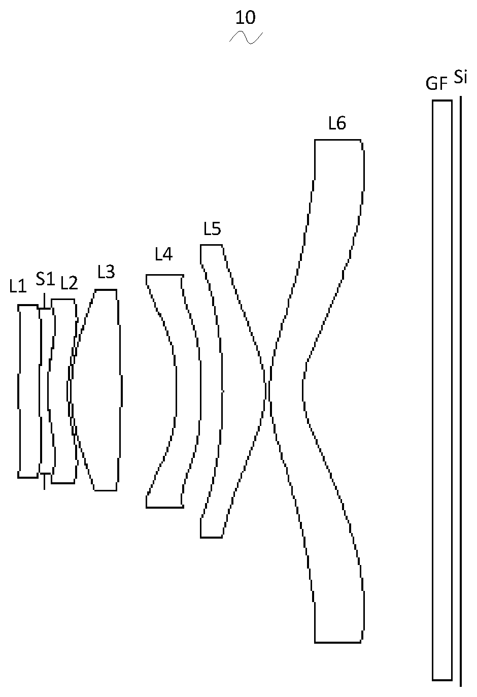
[0004] FIG. 1 is a schematic diagram of a camera optical lens in accordance with a first embodiment of the present invention;
[0005] FIG. 2 shows the longitudinal aberration of the camera optical lens shown in FIG. 1;
[0006] FIG. 3 shows the lateral color of the camera optical lens shown in FIG. 1;
[0007] FIG. 4 presents a schematic diagram of the field curvature and distortion of the camera optical lens shown in FIG. 1;
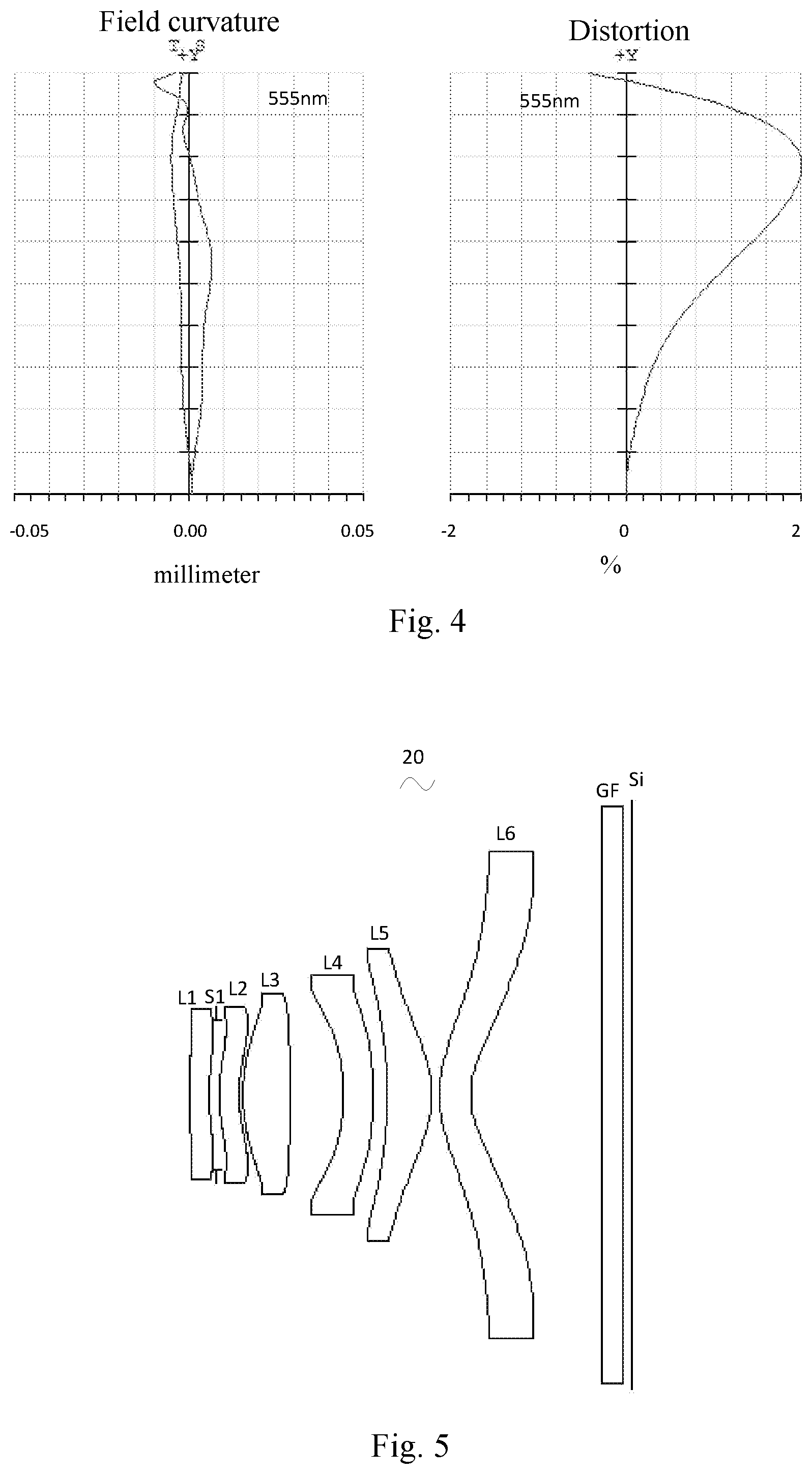
[0008] FIG. 5 is a schematic diagram of a camera optical lens in accordance with a second embodiment of the present invention;
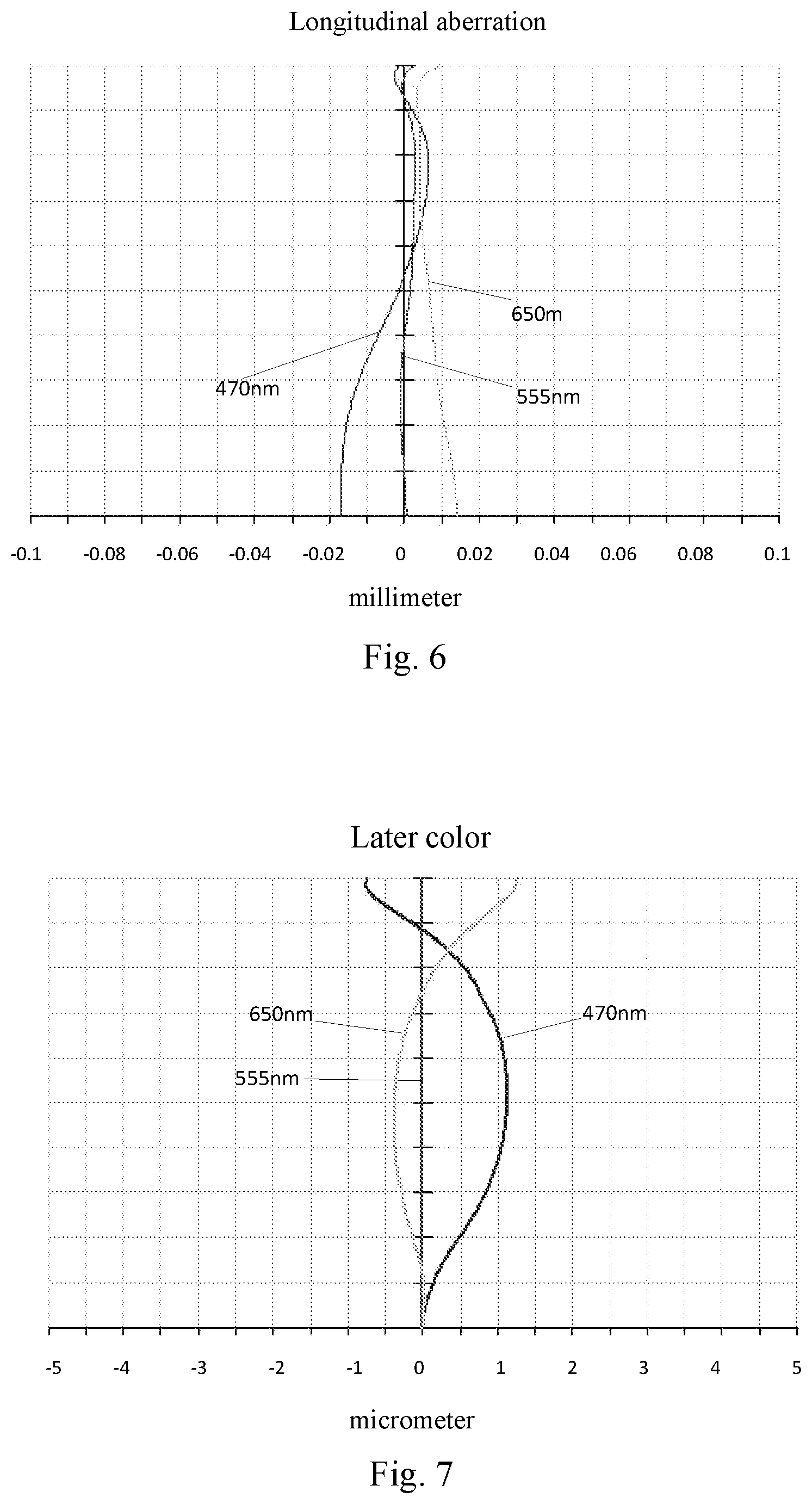
[0009] FIG. 6 presents the longitudinal aberration of the camera optical lens shown in FIG. 5;
[0010] FIG. 7 presents the lateral color of the camera optical lens shown in FIG. 5;
[0011] FIG. 8 presents the field curvature and distortion of the camera optical lens shown in FIG. 5;
[0012] FIG. 9 is a schematic diagram of a camera optical lens in accordance with a third embodiment of the present invention;
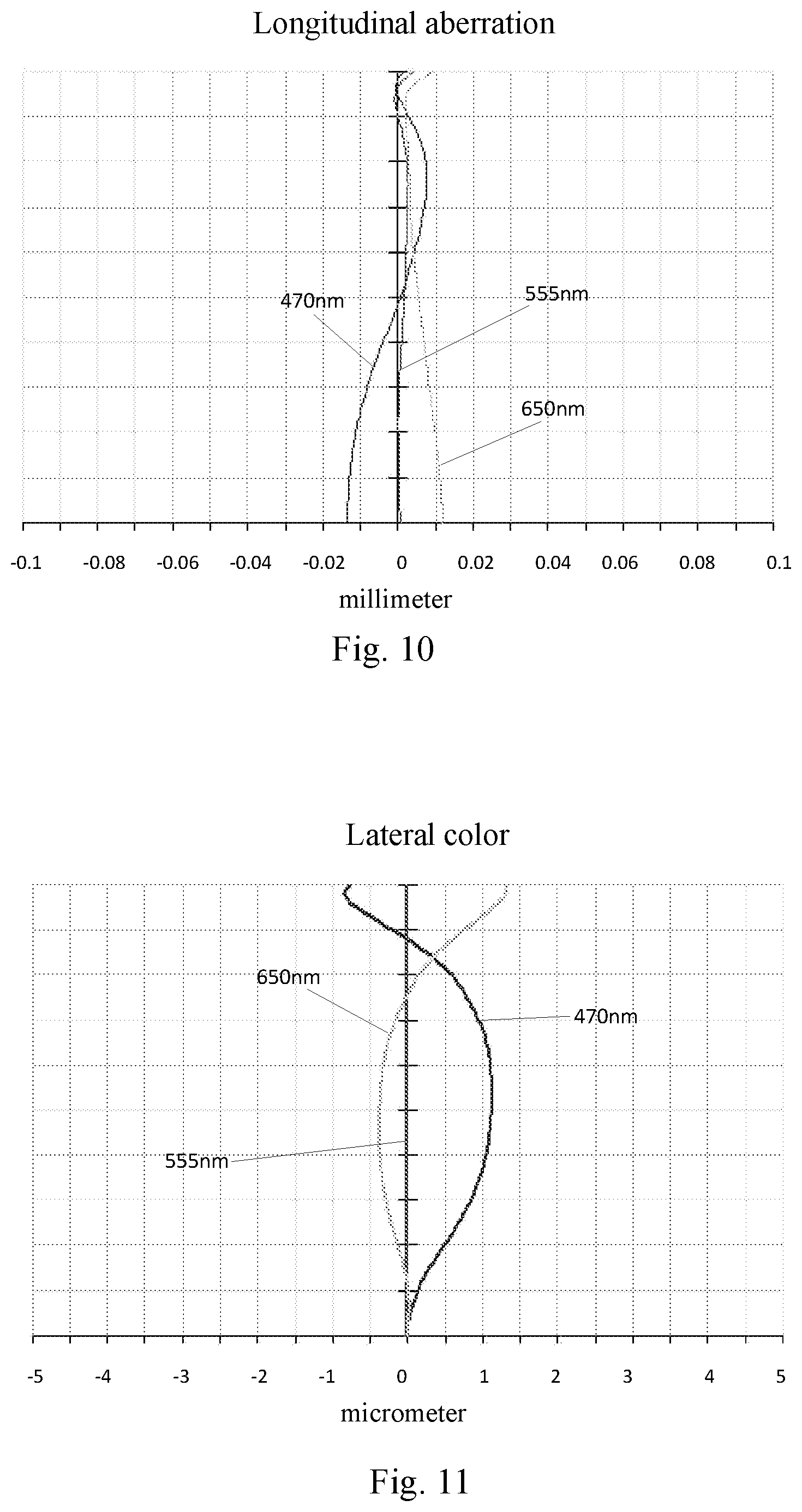
[0013] FIG. 10 presents the longitudinal aberration of the camera optical lens shown in FIG. 9;
[0014] FIG. 11 presents the lateral color of the camera optical lens shown in FIG. 9;
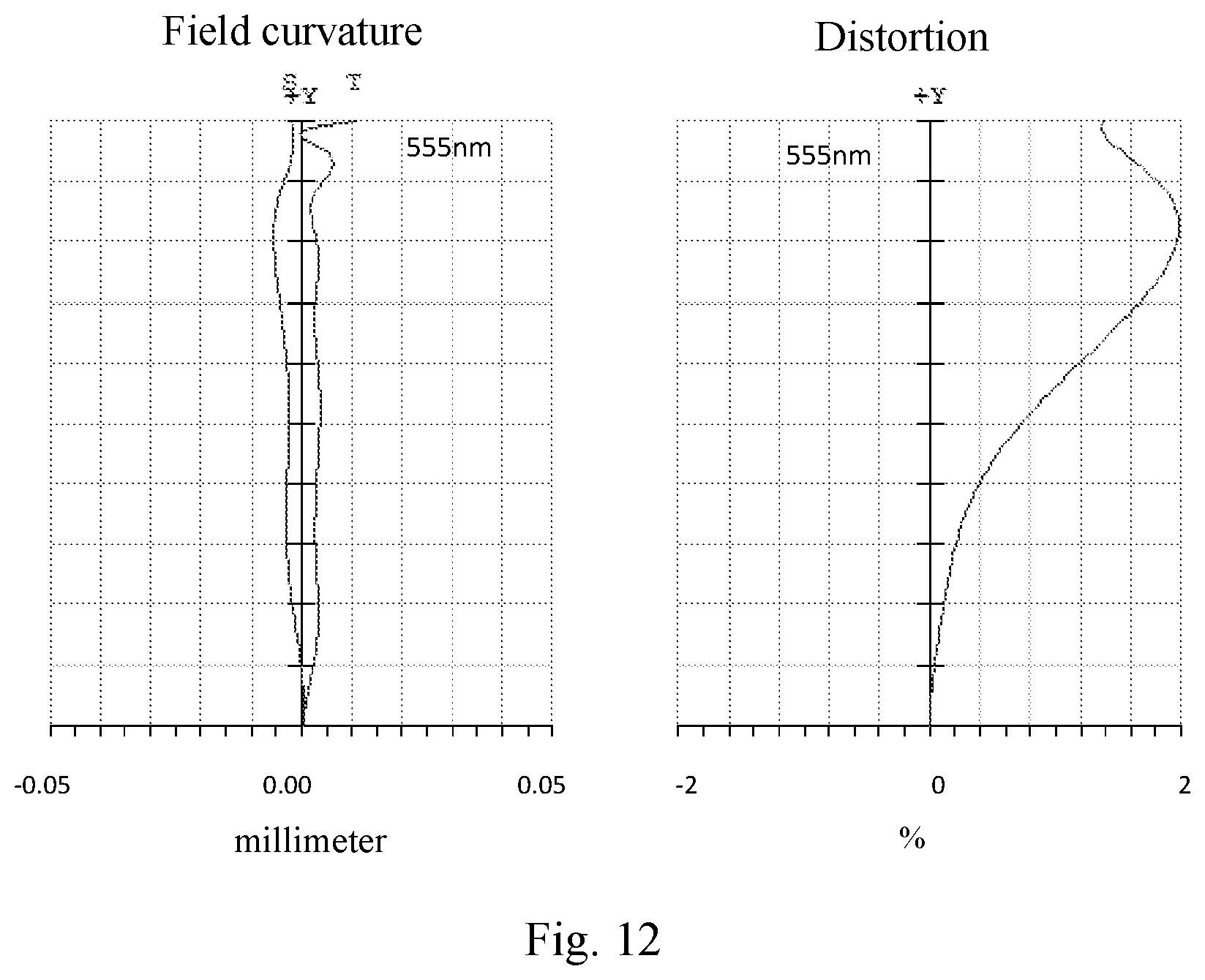
[0015] FIG. 12 presents the field curvature and distortion of the camera optical lens shown in FIG. 9.
DETAILED DESCRIPTION OF THE EXEMPLARY EMBODIMENTS
[0016] The present disclosure will hereinafter be described in detail with reference to several exemplary embodiments. To make the technical problems to be solved, technical solutions and beneficial effects of the present disclosure more apparent, the present disclosure is described in further detail together with the figure and the embodiments. It should be understood the specific embodiments described hereby is only to explain the disclosure, not intended to limit the disclosure.
Embodiment 1
[0017] As referring to FIG. 1, the present invention provides a camera optical lens 10. FIG. 1 shows the camera optical lens 10 of embodiment 1 of the present invention, the camera optical lens 10 comprises six lenses. Specifically, from the object side to the image side, the camera optical lens 10 comprises in sequence: a first lens L1, an aperture S1, a second lens L2, a third lens L3, a fourth lens L4, a fifth lens L5, and a sixth lens L6. Optical element like optical filter GF can be arranged between the sixth lens L6 and the image surface Si.
[0018] The first lens L1 is made of plastic material, the second lens L2 is made of plastic material, the third lens L3 is made of plastic material, the fourth lens L4 is made of plastic material, the fifth lens L5 is made of plastic material, the sixth lens L6 is made of glass material.
[0019] The second lens L2 has a positive refractive power and the third lens L3 has a positive refractive power.
[0020] Here, the focal length of the camera optical lens 10 is defined as f, the focal length of the first lens L1 is defined as f1, the refractive power of the sixth lens L6 is defined as n6, the thickness on-axis of the sixth lens L6 is defined as d11 and the total optical length of the camera optical lens is defined as TTL. The camera optical lens 10 satisfies the following conditions: -3.ltoreq.f1/f.ltoreq.-1, 1.7.ltoreq.n6.ltoreq.2.2, 0.03.ltoreq.d11/TTL.ltoreq.0.075.
[0021] Condition -3.ltoreq.f1/f.ltoreq.-1 fixes the negative refractive power of the first lens L1. If the upper limit of the set value is exceeded, although it benefits the ultra-thin development of lenses, the negative refractive power of the first lens L1 will be too strong, problem like aberration is difficult to be corrected, and it is also unfavorable for wide-angle development of lens. On the contrary, if the lower limit of the set value is exceeded, the negative refractive power of the first lens becomes too weak, it is then difficult to develop ultra-thin lenses. Preferably, the following condition shall be satisfied, -2.997.ltoreq.f1/f.ltoreq.-1.535.
[0022] Condition 1.7.ltoreq.n6.ltoreq.2.2 fixes the refractive power of the sixth lens L6, and refractive power within this range benefits the ultra-thin development of lenses, and it also benefits the correction of aberration. Preferably, the following condition shall be satisfied, 1.701.ltoreq.n6.ltoreq.2.046.
[0023] Condition 0.03.ltoreq.d11/TTL.ltoreq.0.075 fixes the ratio between the thickness on-axis d11 of the sixth lens L6 and the total optical length TTL of the camera optical lens, and it benefits the ultra-thin development of lenses. Preferably, the following condition shall be satisfied, 0.0475.ltoreq.d11/TTL.ltoreq.0.0745.
[0024] When the focal length of the camera optical lens 10 of the present invention, the focal length of each lens, the refractive power of the related lens, and the total optical length, the thickness on-axis and the curvature radius of the camera optical lens satisfy the above conditions, the camera optical lens 10 has the advantage of high performance and satisfies the design requirement of low TTL.
[0025] In this embodiment, the object side surface of the first lens L1 is a convex surface relative to the proximal axis, its image side surface is a concave surface relative to the proximal axis, and it has negative refractive power; the curvature radius of the object side surface of the first lens L1 is defined as R1, the curvature radius of the image side surface of the first lens L1 is defined as R2, the thickness on-axis of the first lens L1 is defined as d1 and the total optical length of the camera optical lens is defined as TTL, the condition 1.01.ltoreq.(R1+R2)/(R1-R2).ltoreq.5.68 fixes the shape of the first lens L1, so that the first lens L1 can effectively correct system spherical aberration; when the condition 0.02.ltoreq.d1/TTL.ltoreq.0.07 is met, it is beneficial for the realization of ultra-thin lenses. Preferably, the following conditions shall be satisfied: 1.61.ltoreq.(R1+R2)/(R1-R2).ltoreq.4.55; 0.04.ltoreq.d1/TTL.ltoreq.0.05.
[0026] In this embodiment, the object side surface of the second lens L2 is a convex surface relative to the proximal axis, its image side surface is a concave surface relative to the proximal axis, and it has positive refractive power; the focal length of the camera optical lens 10 is defined as f, the focal length of the second lens L2 is defined as f2, the curvature radius of the object side surface of the second lens L2 is defined as R3, the curvature radius of image side surface of the second lens L2 is defined as R4, the thickness on-axis of the second lens L2 is defined as d3 and the total optical length of the camera optical lens is defined as TTL, they satisfy the following condition: 10.8.ltoreq.f2/f.ltoreq.275.23, when the condition is met, the positive refractive power of the second lens L2 is controlled within reasonable scope, the spherical aberration caused by the first lens L1 which has negative refractive power and the field curvature of the system then can be reasonably and effectively balanced; the condition 17.49.ltoreq.(R3+R4)/(R3-R4).ltoreq.89.21 fixes the shape of the second lens L2, when beyond this range, with the development into the direction of ultra-thin and wide-angle lenses, problem like on-axis chromatic aberration is difficult to be corrected; if the condition 0.02.ltoreq.d3/TTL.ltoreq.0.07 is met, it is beneficial for the realization of ultra-thin lenses. Preferably, the following conditions shall be satisfied: 17.28.ltoreq.f2/f.ltoreq.220.18; 27.99.ltoreq.(R3+R4)/(R3-R4).ltoreq.71.37; 0.04.ltoreq.d3/TTL.ltoreq.0.05.
[0027] In this embodiment, the object side surface of the third lens L3 is a convex surface relative to the proximal axis, its image side surface is a convex surface relative to the proximal axis, and it has positive refractive power; the focal length of the camera optical lens 10 is defined as f, the focal length of the third lens L3 is defined as f3, the curvature radius of the object side surface of the third lens L3 is defined as R5, the curvature radius of the image side surface of the third lens L3 is defined as R6, the thickness on-axis of the third lens L3 is defined as d5 and the total optical length of the camera optical lens is defined as TTL, they satisfy the condition: 0.35.ltoreq.f3/f.ltoreq.1.16, the appropriate distribution of refractive power makes it possible that the system has better imaging quality and lower sensitivity; the condition -1.57.ltoreq.(R5+R6)/(R5-R6).ltoreq.-0.51 fixes the shape of the third lens L3, when beyond this range, with the development into the direction of ultra-thin and wide-angle lens, the problem like chromatic aberration is difficult to be corrected; when the condition 0.05.ltoreq.d5/TTL.ltoreq.0.17 is met, it is beneficial for the realization of ultra-thin lenses. Preferably, the following conditions shall be satisfied: 0.56.ltoreq.f3/f.ltoreq.0.93; -0.98.ltoreq.(R5+R6)/(R5-R6).ltoreq.-0.64; 0.08.ltoreq.d5/TTL.ltoreq.0.14.
[0028] In this embodiment, the object side surface of the fourth lens L4 is a concave surface relative to the proximal axis, its image side surface is a convex surface relative to the proximal axis, and it has negative refractive power; the focal length of the camera optical lens 10 is defined as f, the focal length of the fourth lens L4 is defined as f4, the curvature radius of the object side surface of the fourth lens L4 is defined as R7, the curvature radius of the image side surface of the fourth lens L4 is defined as R8, the thickness on-axis of the fourth lens L4 is defined as d7 and the total optical length of the camera optical lens is defined as TTL, they satisfy the condition: -3.77.ltoreq.f4/f.ltoreq.-1.08, the appropriate distribution of refractive power makes it possible that the system has better imaging quality and lower sensitivity; the condition -5.99.ltoreq.(R7+R8)/(R7-R8).ltoreq.-1.62 fixes the shape of the fourth lens L4, when beyond this range, with the development into the direction of ultra-thin and wide-angle lens, the problem like chromatic aberration is difficult to be corrected; when the condition 0.03.ltoreq.d7/TTL.ltoreq.0.11 is met, it is beneficial for realization of ultra-thin lenses. Preferably, the following conditions shall be satisfied: -2.36.ltoreq.f4/f.ltoreq.-1.36; -3.74.ltoreq.(R7+R8)/(R7-R8).ltoreq.-2.02; 0.04.ltoreq.d7/TTL.ltoreq.0.09.
[0029] In this embodiment, the object side surface of the fifth lens L5 is a concave surface relative to the proximal axis, its image side surface is a convex surface relative to the proximal axis, and it has positive refractive power; the focal length of the camera optical lens 10 is defined as f, the focal length of the fifth lens L5 is defined as f5, the curvature radius of the object side surface of the fifth lens L5 is defined as R9, the curvature radius of the image side surface of the fifth lens L5 is defined as R10, the thickness on-axis of the fifth lens L5 is defined as d9 and the total optical length of the camera optical lens is defined as TTL, they satisfy the condition: 0.31.ltoreq.f5/f.ltoreq.1.06, the limitation on the fifth lens L5 can effectively make the light angle of the camera lens flat and the tolerance sensitivity reduces; the condition 0.79.ltoreq.(R9+R10)/(R9-R10).ltoreq.2.47 fixes the shape of the fifth lens L5, when beyond this range, with the development into the direction of ultra-thin and wide-angle lens, the problem like off-axis chromatic aberration is difficult to be corrected; when the condition 0.05.ltoreq.d9/TTL.ltoreq.0.16 is met, it is beneficial for the realization of ultra-thin lens. Preferably, the following conditions shall be satisfied: 0.5.ltoreq.f5/f.ltoreq.0.85; 1.26.ltoreq.(R9+R10)/(R9-R10).ltoreq.1.97; 0.08.ltoreq.d9/TTL.ltoreq.0.13.
[0030] In this embodiment, the object side surface of the sixth lens L6 is a convex surface relative to the proximal axis, its image side surface is a concave surface relative to the proximal axis, and it has negative refractive power; the focal length of the camera optical lens 10 is defined as f, the focal length of the sixth lens L6 is defined as f6, the curvature radius of the object side surface of the sixth lens L6 is defined as R11, the curvature radius of the image side surface of the sixth lens L6 is defined as R12, the thickness on-axis of the sixth lens L6 is defined as d11 and the total optical length of the camera optical lens is defined as TTL, they satisfy the condition: -2.13.ltoreq.f6/f.ltoreq.-0.53, the appropriate distribution of refractive power makes it possible that the system has better imaging quality and lower sensitivity; the condition 1.62.ltoreq.(R11+R12)/(R11-R12).ltoreq.6.66 fixes the shape of the sixth lens L6, when beyond this range, with the development into the direction of ultra-thin and wide-angle lenses, the problem like off-axis chromatic aberration is difficult to be corrected; when the condition 0.03.ltoreq.d11/TTL.ltoreq.0.11 is met, it is beneficial for the realization of ultra-thin lens. Preferably, the following conditions shall be satisfied: -1.33.ltoreq.f6/f.ltoreq.-0.66; 2.59.ltoreq.(R11+R12)/(R11-R12).ltoreq.5.32; 0.05.ltoreq.d11/TTL.ltoreq.0.09.
[0031] In this embodiment, the focal length of the camera optical lens 10 is defined as f and the combined focal length of the first lens and the second lens is defined as f12, when the condition -5.72.ltoreq.f12/f.ltoreq.-1.34 is met, the aberration and distortion of the camera lens can be eliminated, and the back focus of the camera lens can be suppressed and the miniaturization characteristics can be maintained. Preferably, the following conditions shall be satisfied: -3.58.ltoreq.f12/f.ltoreq.-1.67.
[0032] In this embodiment, the total optical length TTL of the camera optical lens 10 is less than or equal to 5.18 mm, it is beneficial for the realization of ultra-thin lenses. Preferably, the total optical length TTL of the camera optical lens 10 is less than or equal to 4.95 mm.
[0033] In this embodiment, the aperture F number of the camera optical lens 10 is less than or equal to 2.25. A large aperture has better imaging performance. Preferably, the aperture F number of the camera optical lens 10 is less than or equal to 2.20.
[0034] With such design, the total optical length TTL of the camera optical lens 10 can be made as short as possible, thus the miniaturization characteristics can be maintained.
[0035] In the following, an example will be used to describe the camera optical lens 10 of the present invention. The symbols recorded in each example are as follows. The unit of focal length, distance on-axis, curvature radius, thickness on-axis, inflexion point position and arrest point position is mm.
[0036] TTL: Optical length (the distance on-axis from the object side surface to the image surface of the first lens L1).
[0037] Preferably, inflexion points and/or arrest points can also be arranged on the object side surface and/or image side surface of the lens, so that the demand for high quality imaging can be satisfied, the description below can be referred for specific implementable scheme.
[0038] The design information of the camera optical lens 10 in the first embodiment of the present invention is shown in the tables 1 and 2.
TABLE-US-00001 TABLE 1 R d nd .nu.d R1 7.181 d0= 0.215 nd1 1.5352 .nu.1 56.09 R2 2.412 d1= 0.062 S1 .infin. d2= 0.030 R3 1.379 d3= 0.215 nd2 1.6613 .nu.2 20.37 R4 1.305 d4= 0.035 R5 1.393 d5= 0.530 nd3 1.5352 .nu.3 56.09 R6 -10.760 d6= 0.595 R7 -1.985 d7= 0.257 nd4 1.6613 .nu.4 20.37 R8 -3.976 d8= 0.230 R9 -4.047 d9= 0.452 nd5 1.5352 .nu.5 56.09 R10 -0.908 d10= 0.049 R11 1.247 d11= 0.350 nd6 1.7015 .nu.6 41.24 R12 0.659 d12= 1.380 R13 .infin. d13= 0.210 ndg 1.5168 .nu.g 64.17 R14 .infin. d14= 0.100
[0039] In which, the meaning of the various symbols is as follows.
[0040] S1: Aperture;
[0041] R: The curvature radius of the optical surface, the central curvature radius in case of lens;
[0042] R1: The curvature radius of the object side surface of the first lens L1;
[0043] R2: The curvature radius of the image side surface of the first lens L1;
[0044] R3: The curvature radius of the object side surface of the second lens L2;
[0045] R4: The curvature radius of the image side surface of the second lens L2;
[0046] R5: The curvature radius of the object side surface of the third lens L3;
[0047] R6: The curvature radius of the image side surface of the third lens L3;
[0048] R7: The curvature radius of the object side surface of the fourth lens L4;
[0049] R8: The curvature radius of the image side surface of the fourth lens L4;
[0050] R9: The curvature radius of the object side surface of the fifth lens L5;
[0051] R10: The curvature radius of the image side surface of the fifth lens L5;
[0052] R11: The curvature radius of the object side surface of the sixth lens L6;
[0053] R12: The curvature radius of the image side surface of the sixth lens L6;
[0054] R13: The curvature radius of the object side surface of the optical filter GF;
[0055] R14: The curvature radius of the image side surface of the optical filter GF;
[0056] d: The thickness on-axis of the lens and the distance on-axis between the lens;
[0057] d0: The distance on-axis from aperture S1 to the object side surface of the first lens L1;
[0058] d1: The thickness on-axis of the first lens L1;
[0059] d2: The distance on-axis from the image side surface of the first lens L1 to the object side surface of the second lens L2;
[0060] d3: The thickness on-axis of the second lens L2;
[0061] d4: The distance on-axis from the image side surface of the second lens L2 to the object side surface of the third lens L3;
[0062] d5: The thickness on-axis of the third lens L3;
[0063] d6: The distance on-axis from the image side surface of the third lens L3 to the object side surface of the fourth lens L4;
[0064] d7: The thickness on-axis of the fourth lens L4;
[0065] d8: The distance on-axis from the image side surface of the fourth lens L4 to the object side surface of the fifth lens L5;
[0066] d9: The thickness on-axis of the fifth lens L5;
[0067] d10: The distance on-axis from the image side surface of the fifth lens L5 to the object side surface of the sixth lens L6;
[0068] d11: The thickness on-axis of the sixth lens L6;
[0069] d12: The distance on-axis from the image side surface of the sixth lens L6 to the object side surface of the optical filter GF;
[0070] d13: The thickness on-axis of the optical filter GF;
[0071] d14: The distance on-axis from the image side surface to the image surface of the optical filter GF;
[0072] nd: The refractive power of the d line;
[0073] nd1: The refractive power of the d line of the first lens L1;
[0074] nd2: The refractive power of the d line of the second lens L2;
[0075] nd3: The refractive power of the d line of the third lens L3;
[0076] nd4: The refractive power of the d line of the fourth lens L4;
[0077] nd5: The refractive power of the d line of the fifth lens L5;
[0078] nd6: The refractive power of the d line of the sixth lens L6;
[0079] ndg: The refractive power of the d line of the optical filter GF;
[0080] vd: The abbe number;
[0081] v1: The abbe number of the first lens L1;
[0082] v2: The abbe number of the second lens L2;
[0083] v3: The abbe number of the third lens L3;
[0084] v4: The abbe number of the fourth lens L4;
[0085] v5: The abbe number of the fifth lens L5;
[0086] v6: The abbe number of the sixth lens L6;
[0087] vg: The abbe number of the optical filter GF;
[0088] Table 2 shows the aspherical surface data of the camera optical lens 10 in the embodiment 1 of the present invention.
TABLE-US-00002 TABLE 2 Conic Index Aspherical Surface Index k A4 A6 A8 A10 A12 A14 A16 R1 -5.5503E+01 -1.4700E-01 2.1937E-01 -3.7646E-01 3.1324E-01 4.8749E-02 -2.6040E-01 1.0601E-01 R2 -2.7532E+01 -3.3797E-01 2.1250E-01 -1.4635E-02 5.6901E-02 -3.2605E-01 2.9800E-01 -8.8697E-02 R3 -6.1613E+00 -2.2036E-01 -2.7491E-01 3.6987E-01 8.0348E-02 -2.2225E-01 -4.8561E-01 5.0454E-01 R4 -2.4321E+00 -2.6133E-01 -2.4029E-01 3.6076E-01 -5.3565E-02 -2.0523E-01 -1.3254E-02 1.3212E-01 R5 5.0230E-01 -2.4420E-01 1.0023E-01 -4.3782E-02 2.0302E-02 -2.0017E-01 2.3962E-01 -9.9321E-02 R6 9.9395E+01 -1.9755E-02 1.0023E-01 -5.5380E-02 8.9305E-03 -1.3540E-02 -4.3263E-02 3.4271E-02 R7 -1.8759E-01 -1.4763E-01 4.0500E-02 3.5562E-02 2.5052E-02 -1.7954E-02 -2.0469E-02 5.0169E-04 R8 3.0593E+00 -1.8379E-01 1.0666E-01 9.5575E-03 1.4726E-02 9.9784E-03 2.5622E-03 -6.3302E-03 R9 7.2219E+00 1.4736E-02 -1.7130E-02 2.3787E-02 -1.6426E-03 -5.8364E-03 -1.6503E-03 2.0736E-03 R10 -4.8837E+00 -2.1010E-02 5.2892E-02 -1.3563E-02 -3.5509E-03 5.2658E-04 3.5345E-04 -3.0884E-05 R11 -4.7780E+00 -4.6853E-02 9.8313E-03 -3.7390E-04 -1.2591E-04 2.7123E-06 4.0169E-06 -4.3226E-07 R12 -3.9337E+00 -4.0927E-02 8.5791E-03 -9.0113E-04 -2.5853E-05 1.4944E-05 -8.2964E-07 -3.7494E-08
[0089] Among them, K is a conic index, A4, A6, A8, A10, A12, A14, A16 are aspheric surface indexes.
[0090] IH: Image Height
y=(x.sup.2/R)/[1+{1-(k+1)(x.sup.2/R.sup.2)}.sup.1/2]+A4x.sup.4+A6x.sup.6- +A8x.sup.8+A10x.sup.10+A12x.sup.12+A14x.sup.14+A16x.sup.16 (1)
[0091] For convenience, the aspheric surface of each lens surface uses the aspheric surfaces shown in the above condition (1). However, the present invention is not limited to the aspherical polynomials form shown in the condition (1).
[0092] Table 3 and table 4 show the inflexion points and the arrest point design data of the camera optical lens 10 lens in embodiment 1 of the present invention. In which, P1R1 and P1R2 represent respectively the object side surface and image side surface of the first lens L1, P2R1 and P2R2 represent respectively the object side surface and image side surface of the second lens L2, P3R1 and P3R2 represent respectively the object side surface and image side surface of the third lens L3, P4R1 and P4R2 represent respectively the object side surface and image side surface of the fourth lens L4, P5R1 and P5R2 represent respectively the object side surface and image side surface of the fifth lens L5, P6R1 and P6R2 represent respectively the object side surface and image side surface of the sixth lens L6. The data in the column named "inflexion point position" are the vertical distances from the inflexion points arranged on each lens surface to the optic axis of the camera optical lens 10. The data in the column named "arrest point position" are the vertical distances from the arrest points arranged on each lens surface to the optic axis of the camera optical lens 10.
TABLE-US-00003 TABLE 3 inflexion point inflexion point inflexion point inflexion point number position 1 position 2 position 3 P1R1 1 0.305 P1R2 1 0.275 P2R1 1 0.375 P2R2 1 0.415 P3R1 1 0.865 P3R2 0 P4R1 2 0.815 1.015 P4R2 1 0.825 P5R1 1 1.225 P5R2 3 0.735 1.275 1.415 P6R1 1 0.745 P6R2 1 0.685
TABLE-US-00004 TABLE 4 arrest point number arrest point position 1 P1R1 1 0.565 P1R2 1 0.525 P2R1 1 0.665 P2R2 1 0.715 P3R1 0 P3R2 0 P4R1 0 P4R2 1 1.075 P5R1 0 P5R2 0 P6R1 1 2.325 P6R2 1 2.215
[0093] FIG. 2 and FIG. 3 show the longitudinal aberration and lateral color schematic diagrams after light with a wavelength of 470 nm, 555 nm and 650 nm passes the camera optical lens 10 in the first embodiment. FIG. 4 shows the field curvature and distortion schematic diagrams after light with a wavelength of 555 nm passes the camera optical lens 10 in the first embodiment, the field curvature S in FIG. 4 is a field curvature in the sagittal direction, T is a field curvature in the meridian direction.
[0094] Table 13 shows the various values of the examples 1, 2, 3 and the values corresponding with the parameters which are already specified in the conditions.
[0095] As shown in Table 13, the first embodiment satisfies the various conditions.
[0096] In this embodiment, the pupil entering diameter of the camera optical lens is 1.66 mm, the full vision field image height is 2.933 mm, the vision field angle in the diagonal direction is 83.19.degree., it has wide-angle and is ultra-thin, its on-axis and off-axis chromatic aberrations are fully corrected, and it has excellent optical characteristics.
Embodiment 2
[0097] Embodiment 2 is basically the same as embodiment 1, the meaning of its symbols is the same as that of embodiment 1, in the following, only the differences are described.
[0098] Table 5 and table 6 show the design data of the camera optical lens 20 in embodiment 2 of the present invention.
TABLE-US-00005 TABLE 5 R d nd .nu.d R1 3.843 d0= 0.213 nd1 1.5352 .nu.1 56.09 R2 2.013 d1= 0.077 S1 .infin. d2= 0.027 R3 1.387 d3= 0.213 nd2 1.6613 .nu.2 20.37 R4 1.341 d4= 0.041 R5 1.491 d5= 0.503 nd3 1.5352 .nu.3 56.09 R6 -12.070 d6= 0.564 R7 -1.997 d7= 0.312 nd4 1.6613 .nu.4 20.37 R8 -4.717 d8= 0.153 R9 -4.076 d9= 0.474 nd5 1.5352 .nu.5 56.09 R10 -0.995 d10= 0.082 R11 1.144 d11= 0.330 nd6 1.8340 .nu.6 37.17 R12 0.715 d12= 1.401 R13 .infin. d13= 0.210 ndg 1.5168 .nu.g 64.17 R14 .infin. d14= 0.100
[0099] Table 6 shows the aspherical surface data of each lens of the camera optical lens 20 in embodiment 2 of the present invention.
TABLE-US-00006 TABLE 6 Conic Index Aspherical Surface Index k A4 A6 A8 A10 A12 A14 A16 R1 -1.4763E-01 -1.5575E-02 2.0282E-01 -2.9237E-01 2.1497E-01 -1.5633E-03 -9.2641E-02 1.9335E-02 R2 -1.7721E-01 -2.9183E-01 1.4541E-01 -2.1356E-02 1.5842E-01 -3.7643E-01 1.0200E-01 1.1181E-01 R3 -5.7995E-00 -2.1240E-01 -2.2683E-01 3.2371E-01 -5.4094E-02 -1.4843E-01 -1.6983E-01 1.4502E-01 R4 -3.0899E-00 -2.3792E-01 -1.7426E-01 2.4093E-01 -6.0359E-02 -1.5370E-01 -3.6018E-02 1.2494E-01 R5 9.3942E-01 -2.2714E-01 8.6732E-02 -6.3850E-02 -1.6153E-02 -1.8238E-01 2.6512E-01 -1.4020E-01 R6 1.1325E-02 -2.0283E-02 8.6732E-02 -6.3565E-02 3.0916E-03 -8.9216E-03 -3.8152E-02 2.2923E-02 R7 -2.8166E-01 -1.3403E-01 2.9233E-02 5.6079E-02 7.5890E-03 5.3597E-04 4.3111E-03 -1.5133E-02 R8 1.2255E-01 -1.7139E-01 9.0380E-02 5.1857E-03 1.2014E-02 7.2537E-03 6.5507E-04 -3.1934E-03 R9 7.3921E-00 1.5925E-02 -8.5124E-03 2.2426E-02 -1.8237E-03 -5.1409E-03 -1.3690E-03 1.7332E-03 R10 -3.9443E-00 -8.0604E-03 4.7326E-02 -1.2600E-02 -3.2833E-03 4.6011E-04 3.2024E-04 -2.7622E-03 R11 -3.9399E-00 -4.6050E-02 8.4556E-03 -3.1812E-04 -1.0459E-04 2.4634E-06 3.6435E-06 -3.9614E-07 R12 -3.6220E-00 -4.1436E-02 8.2169E-03 -8.0412E-04 -3.7118E-05 1.4656E-05 -6.5783E-07 -3.8426E-03
[0100] Table 7 and table 8 show the inflexion points and the arrest point design data of the camera optical lens 20 lens in the second embodiment of the present invention.
TABLE-US-00007 TABLE 7 inflexion point inflexion point inflexion point inflexion point number position 1 position 2 position 3 P1R1 1 0.415 P1R2 1 0.315 P2R1 1 0.385 P2R2 1 0.415 P3R1 1 0.735 P3R2 0 P4R1 2 0.905 0.975 P4R2 1 0.855 P5R1 2 1.205 1.345 P5R2 3 0.745 1.295 1.435 P6R1 1 0.775 P6R2 1 0.725
TABLE-US-00008 TABLE 8 arrest point number arrest point position 1 P1R1 1 0.765 P1R2 1 0.605 P2R1 1 0.675 P2R2 1 0.715 P3R1 0 P3R2 0 P4R1 0 P4R2 1 1.115 P5R1 0 P5R2 0 P6R1 1 2.295 P6R2 1 2.225
[0101] FIG. 6 and FIG. 7 show the longitudinal aberration and lateral color schematic diagrams after light with a wavelength of 470 nm, 555 nm and 650 nm passes the camera optical lens 20 in the second embodiment. FIG. 8 shows the field curvature and distortion schematic diagrams after light with a wavelength of 555 nm passes the camera optical lens 20 in the second embodiment.
[0102] As shown in Table 13, the second embodiment satisfies the various conditions.
[0103] In this embodiment, the pupil entering diameter of the camera optical lens is 1.508 mm, the full vision field image height is 2.933 mm, the vision field angle in the diagonal direction is 82.94.degree., it has wide-angle and is ultra-thin, its on-axis and off-axis chromatic aberrations are fully corrected, and it has excellent optical characteristics.
Embodiment 3
[0104] Embodiment 3 is basically the same as embodiment 1, the meaning of its symbols is the same as that of embodiment 1, in the following, only the differences are described.
[0105] The design information of the camera optical lens 30 in the third embodiment of the present invention is shown in the tables 9 and 10.
TABLE-US-00009 TABLE 9 R d nd .nu.d R1 3.586 d0= 0.215 nd1 1.5352 .nu.1 56.09 R2 2.088 d1= 0.077 S1 .infin. d2= 0.031 R3 1.458 d3= 0.215 nd2 1.6613 .nu.2 20.37 R4 1.377 d4= 0.038 R5 1.506 d5= 0.495 nd3 1.5352 .nu.3 56.09 R6 -12.392 d6= 0.545 R7 -1.972 d7= 0.339 nd4 1.6613 .nu.4 20.37 R8 -4.738 d8= 0.135 R9 -4.078 d9= 0.494 nd5 1.5352 .nu.5 56.09 R10 -0.974 d10= 0.128 R11 1.119 d11= 0.305 nd6 1.8919 .nu.6 37.13 R12 0.707 d12= 1.375 R13 .infin. d13= 0.210 ndg 1.5168 .nu.g 64.17 R14 .infin. d14= 0.100
[0106] Table 10 shows the aspherical surface data of each lens of the camera optical lens 30 in embodiment 3 of the present invention.
TABLE-US-00010 TABLE 10 Conic Index Aspherical Surface Index k A4 A6 A8 A10 A12 A14 A16 R1 -1.0381E-01 -1.5274E-01 1.9306E-01 -2.9638E-01 2.2371E-01 -6.9116E-04 -9.7343E-02 1.4653E-02 R2 -1.6906E-01 -2.9027E-01 1.3969E-01 -3.2986E-02 1.5256E-01 -3.5482E-01 1.2712E-01 6.7271E-02 R3 -5.9946E-00 -2.1443E-01 -2.2904E-01 3.2556E-01 -5.6957E-02 -1.4979E-01 -1.8741E-01 1.2041E-01 R4 -3.2256E+00 -2.3875E-01 -1.7055E-01 2.3626E-01 -6.7917E-02 -1.6267E-01 -3.2324E-02 1.2265E-01 R5 9.9736E-01 -2.2992E-01 3.1868E-02 -5.9900E-02 -1.7430E-02 -1.8313E-01 2.5917E-01 -1.4033E-01 R6 1.2978E-02 -2.5653E-02 8.1668E-02 -5.5203E-02 6.2182E-04 -1.1032E-02 -4.0558E-02 2.2092E-02 R7 -1.3114E-01 -1.4084E-01 3.2444E-02 5.7446E-02 1.1148E-02 1.6233E-03 4.7233E-03 -1.8970E-02 R8 1.1964E+01 -1.7089E-01 8.9682E-02 4.5408E-03 1.1853E-02 7.1596E-03 5.9293E-04 -3.3180E-03 R9 7.4846E-00 1.6780E-02 -7.5400E-03 2.2375E-02 -1.9574E-03 -5.2322E-03 -1.3769E-03 1.7641E-03 R10 -3.8277E-00 -8.4009E-03 4.7600E-02 -1.2553E-02 -3.2301E-03 4.7099E-04 3.1964E-04 -3.9546E-05 R11 -3.8133E-00 -4.5526E-02 8.2671E-03 -3.1610E-04 -1.0508E-04 2.4543E-06 3.6638E-06 -3.8674E-07 R12 -3.5077E-00 -4.1720E-02 8.3946E-03 -3.3439E-04 -1.6336E-05 1.4743E-05 -6.4076E-07 -3.6162E-03
[0107] Table 11 and table 12 show the inflexion points and the arrest point design data of the camera optical lens 30 lens in embodiment 3 of the present invention.
TABLE-US-00011 TABLE 11 inflexion point inflexion point inflexion point number position 1 position 2 P1R1 1 0.445 P1R2 1 0.315 P2R1 1 0.375 P2R2 1 0.415 P3R1 1 0.715 P3R2 0 P4R1 2 0.905 0.945 P4R2 1 0.865 P5R1 2 1.215 1.335 P5R2 2 0.745 1.275 P6R1 1 0.785 P6R2 1 0.735
TABLE-US-00012 TABLE 12 arrest point number arrest point position 1 P1R1 1 0.775 P1R2 1 0.595 P2R1 1 0.665 P2R2 1 0.705 P3R1 0 P3R2 0 P4R1 0 P4R2 1 1.125 P5R1 0 P5R2 0 P6R1 1 2.315 P6R2 1 2.255
[0108] FIG. 10 and FIG. 11 show the longitudinal aberration and lateral color schematic diagrams after light with a wavelength of 470 nm, 555 nm and 650 nm passes the camera optical lens 30 in the third embodiment. FIG. 12 shows the field curvature and distortion schematic diagrams after light with a wavelength of 555 nm passes the camera optical lens 30 in the third embodiment.
[0109] The following table 13, in accordance with the above conditions, lists the values in this embodiment corresponding with each condition expression. Apparently, the camera optical system of this embodiment satisfies the above conditions.
[0110] In this embodiment, the pupil entering diameter of the camera optical lens is 1.502 mm, the full vision field image height is 2.933 mm, the vision field angle in the diagonal direction is 82.96.degree., it has wide-angle and is ultra-thin, its on-axis and off-axis chromatic aberrations are fully corrected, and it has excellent optical characteristics.
TABLE-US-00013 TABLE 13 Embodiment Embodiment Embodiment 1 2 3 f 3.319 3.280 3.273 f1 -6.871 -8.211 -9.799 f2 210.537 70.835 600.603 f3 2.333 2.503 2.533 f4 -6.264 -5.443 -5.325 f5 2.076 2.325 2.259 f6 -2.630 -3.499 -3.302 f12 -6.651 -8.657 -9.365 f12/f -2.004 -2.639 -2.861 (R1 + R2)/(R1 - R2) 2.011 3.201 3.788 (R3 + R4)/(R3 - R4) 36.654 59.475 34.985 (R5 + R6)/(R5 - R6) -0.771 -0.780 -0.783 (R7 + R8)/(R7 - R8) -2.994 -2.469 -2.426 (R9 + R10)/(R9 - R10) 1.579 1.646 1.628 (R11 + R12)/(R11 - R12) 3.241 4.330 4.437 f1/f -2.070 -2.503 -2.994 f2/f 63.433 21.595 183.484 f3/f 7.029E-01 7.631E-01 7.738E-01 f4/f -1.887 -1.659 -1.627 f5/f 0.625 0.709 0.690 f6/f -0.793 -1.067 -1.009 f12/f -2.004 -2.639 -2.861 d1 0.215 0.213 0.215 d3 0.215 0.213 0.215 d5 0.530 0.503 0.495 d7 0.257 0.312 0.339 d9 0.452 0.474 0.494 d11 0.350 0.330 0.305 Fno 2.000 2.175 2.180 TTL 4.713 4.701 4.701 d1/TTL 0.046 0.045 0.046 d3/TTL 0.046 0.045 0.046 d5/TTL 0.113 0.107 0.105 d7/TTL 0.055 0.066 0.072 d9/TTL 0.096 0.101 0.105 d11/TTL 0.074 0.070 0.065 n1 1.5352 1.5352 1.5352 n2 1.6613 1.6613 1.6613 n3 1.5352 1.5352 1.5352 n4 1.6613 1.6613 1.6613 n5 1.5352 1.5352 1.5352 n6 1.7015 1.8340 1.8919 v1 56.0934 56.0934 56.0934 v2 20.3729 20.3729 20.3729 v3 56.0934 56.0934 56.0934 v4 20.3729 20.3729 20.3729 v5 56.0934 56.0934 56.0934 v6 41.2394 37.1669 37.1340
[0111] It is to be understood, however, that even though numerous characteristics and advantages of the present exemplary embodiments have been set forth in the foregoing description, together with details of the structures and functions of the embodiments, the disclosure is illustrative only, and changes may be made in detail, especially in matters of shape, size, and arrangement of parts within the principles of the invention to the full extent indicated by the broad general meaning of the terms where the appended claims are expressed.
* * * * *
D00000
D00001
D00002
D00003
D00004
D00005
D00006
D00007
XML
uspto.report is an independent third-party trademark research tool that is not affiliated, endorsed, or sponsored by the United States Patent and Trademark Office (USPTO) or any other governmental organization. The information provided by uspto.report is based on publicly available data at the time of writing and is intended for informational purposes only.
While we strive to provide accurate and up-to-date information, we do not guarantee the accuracy, completeness, reliability, or suitability of the information displayed on this site. The use of this site is at your own risk. Any reliance you place on such information is therefore strictly at your own risk.
All official trademark data, including owner information, should be verified by visiting the official USPTO website at www.uspto.gov. This site is not intended to replace professional legal advice and should not be used as a substitute for consulting with a legal professional who is knowledgeable about trademark law.