Portion capsule having an identifier
Kruger December 22, 2
U.S. patent number 10,870,531 [Application Number 16/860,441] was granted by the patent office on 2020-12-22 for portion capsule having an identifier. This patent grant is currently assigned to K-FEE SYSTEM GMBH. The grantee listed for this patent is K-FEE SYSTEM GMBH. Invention is credited to Marc Kruger.


View All Diagrams
| United States Patent | 10,870,531 |
| Kruger | December 22, 2020 |
Portion capsule having an identifier
Abstract
A method of using a portion capsule for producing a beverage. The method includes providing an apparatus including a barcode reader, the apparatus including a pump adapted to supply heated water; loading the portion capsule into the apparatus; piercing the foil lid; reading a barcode on the portion capsule with the barcode reader; determining whether the read barcode agrees with a stored reference; and activating the pump to push heated water into the portion capsule only upon a determination that the read barcode agrees with the stored reference.
| Inventors: | Kruger; Marc (Gladbach, DE) | ||||||||||
|---|---|---|---|---|---|---|---|---|---|---|---|
| Applicant: |
|
||||||||||
| Assignee: | K-FEE SYSTEM GMBH (Bergisch
Gladbach, DE) |
||||||||||
| Family ID: | 1000005256202 | ||||||||||
| Appl. No.: | 16/860,441 | ||||||||||
| Filed: | April 28, 2020 |
Prior Publication Data
| Document Identifier | Publication Date | |
|---|---|---|
| US 20200255213 A1 | Aug 13, 2020 | |
Related U.S. Patent Documents
| Application Number | Filing Date | Patent Number | Issue Date | ||
|---|---|---|---|---|---|
| 16438818 | Jun 12, 2019 | ||||
| 15646980 | Jul 11, 2017 | ||||
| 15211823 | Jul 15, 2016 | ||||
| 13744623 | Jan 18, 2013 | ||||
| PCT/EP2011/003677 | Jul 22, 2011 | ||||
Foreign Application Priority Data
| Jul 22, 2010 [DE] | 10 2010 031 988 | |||
| Sep 2, 2010 [DE] | 10 2010 044 251 | |||
| Feb 7, 2011 [DE] | 10 2011 010 534 | |||
| Current U.S. Class: | 1/1 |
| Current CPC Class: | A47J 31/4492 (20130101); B65D 85/8043 (20130101); B65D 65/466 (20130101); B65D 2203/10 (20130101); B65D 2203/06 (20130101) |
| Current International Class: | B65D 85/804 (20060101); A47J 31/44 (20060101); B65D 65/46 (20060101) |
References Cited [Referenced By]
U.S. Patent Documents
| 923706 | January 1909 | Richey et al. |
| 1051426 | February 1911 | Matheson |
| 1036589 | November 1911 | Eggleston |
| 1329461 | February 1920 | Frantz |
| 1485200 | February 1924 | Roberts et al. |
| 1689665 | October 1928 | Cramp |
| 2732919 | January 1956 | Johnson |
| 2778739 | January 1957 | Rodth |
| 2847726 | August 1958 | Frick |
| 3039153 | June 1962 | Dusing |
| 3183096 | May 1965 | Hiscock |
| 3261129 | July 1966 | Brydolf et al. |
| 3327428 | June 1967 | Horton et al. |
| 3363588 | January 1968 | Harrington et al. |
| 3416183 | December 1968 | Martin |
| 3473266 | October 1969 | Miller |
| 3480989 | December 1969 | Edeus |
| 3501896 | March 1970 | Stoeser et al. |
| 3611637 | October 1971 | Saino |
| 3631793 | January 1972 | Bednartz |
| 3640727 | February 1972 | Heusinkveld |
| 4081880 | April 1978 | Edeus |
| 4136202 | January 1979 | Favre |
| 4325204 | April 1982 | Martine |
| 4389925 | June 1983 | Piana |
| 4404770 | September 1983 | Markus |
| 4424605 | January 1984 | Squires et al. |
| 4452014 | June 1984 | Markus |
| 4488387 | December 1984 | Foti |
| 4513535 | April 1985 | Uphoff |
| 4534985 | August 1985 | Gasau |
| 4540595 | September 1985 | Acitelli et al. |
| 4633614 | January 1987 | Van Weelden |
| 4651469 | March 1987 | Ngian et al. |
| 4644151 | May 1987 | Piet |
| 4676482 | June 1987 | Reece et al. |
| 4680828 | July 1987 | Cook et al. |
| 4742645 | May 1988 | Johnston |
| 4859337 | August 1989 | Woltermann |
| 4860645 | August 1989 | Van Der Lijn et al. |
| 4867993 | September 1989 | Nordskog |
| 4881346 | November 1989 | Block |
| 4936049 | June 1990 | Hansen |
| 4976179 | December 1990 | Lacrouts-Cazenave |
| 5012629 | May 1991 | Rehman et al. |
| 5028769 | July 1991 | Claypool et al. |
| 5079872 | January 1992 | Short |
| 5108768 | April 1992 | So |
| 5194553 | March 1993 | Freeburne et al. |
| 5242702 | September 1993 | Fond |
| 5243164 | September 1993 | Erickson et al. |
| 5251758 | October 1993 | Kolacek |
| 5285041 | February 1994 | Wright |
| 5301468 | April 1994 | Kameaki |
| 5325765 | July 1994 | Sylvan et al. |
| 5351442 | October 1994 | Gingras |
| 5392986 | February 1995 | Beer et al. |
| 5402707 | April 1995 | Fond et al. |
| 5450693 | September 1995 | Tarrega |
| 5460078 | October 1995 | Weller |
| 5461829 | October 1995 | Lehto et al. |
| 5496573 | March 1996 | Tsuji et al. |
| 5501945 | March 1996 | Kanakkanatt |
| 5535765 | July 1996 | Takashima |
| 5566505 | October 1996 | Kameaki |
| 5601716 | February 1997 | Heinrich et al. |
| 5637850 | June 1997 | Honda |
| 5656311 | August 1997 | Fond |
| 5656318 | August 1997 | Fond et al. |
| 5677522 | October 1997 | Rice et al. |
| 5725261 | March 1998 | Rahn |
| 5742979 | April 1998 | Garcia-Hernando |
| 5840189 | November 1998 | Sylvan et al. |
| 5888549 | March 1999 | Buchholz et al. |
| 5895672 | April 1999 | Cooper |
| 5897899 | April 1999 | Fond |
| 5917165 | June 1999 | Platt et al. |
| 5941055 | August 1999 | Coates |
| 5948455 | September 1999 | Schaeffer et al. |
| 5980743 | November 1999 | Bairischer |
| 5994677 | November 1999 | Akerlind |
| 6082499 | July 2000 | O'Donnell |
| 6153026 | November 2000 | Michotte |
| 6199780 | March 2001 | Gorlitz |
| 6202929 | March 2001 | Verschuur et al. |
| 6213326 | April 2001 | Denner et al. |
| 6250016 | June 2001 | Gravel |
| 6289643 | September 2001 | Bonar |
| 6299926 | October 2001 | Balakrishnan et al. |
| 6440256 | August 2002 | Gordon et al. |
| 6451332 | September 2002 | Tanaka et al. |
| 6589577 | July 2003 | Lazaris et al. |
| 6598800 | July 2003 | Schmit et al. |
| 6607762 | August 2003 | Lazaris et al. |
| 6627244 | September 2003 | Omura |
| 6645537 | November 2003 | Sweeney et al. |
| 6655260 | December 2003 | Lazaris |
| 6817538 | November 2004 | Afzali-Ardakani et al. |
| 6861086 | March 2005 | Buckingham et al. |
| 6871448 | March 2005 | Kline |
| 6948420 | September 2005 | Kirschner et al. |
| 6994879 | February 2006 | Cirigliano et al. |
| 7408094 | August 2008 | Little et al. |
| 7444925 | November 2008 | Mahlich |
| 7464518 | December 2008 | Ansinn |
| 7543527 | June 2009 | Schmed |
| 7552672 | June 2009 | Schmed |
| 7595870 | September 2009 | Ringlien |
| 7673558 | March 2010 | Panesar et al. |
| 7685930 | March 2010 | Mandralis et al. |
| 7712258 | May 2010 | Ewing et al. |
| 7743557 | June 2010 | Liao |
| 7779578 | August 2010 | Gray |
| 7815953 | October 2010 | Mastropasqua et al. |
| 7935646 | May 2011 | Viazmensky et al. |
| 7946217 | May 2011 | Favre et al. |
| 7981451 | July 2011 | Ozanne |
| 8039029 | October 2011 | Ozanne |
| 8039034 | October 2011 | Ozanne |
| 8088423 | January 2012 | Ohresser et al. |
| 8101928 | January 2012 | Hill et al. |
| 8109200 | February 2012 | Hansen |
| 8114461 | February 2012 | Perlman et al. |
| 8163318 | April 2012 | Ozanne et al. |
| 8168908 | May 2012 | Heimann |
| 8257766 | September 2012 | Yoakim et al. |
| 8276639 | October 2012 | Binacchi |
| 8361527 | January 2013 | Winkler et al. |
| 8443549 | May 2013 | Salvietti et al. |
| 8474368 | July 2013 | Kilber et al. |
| 8491948 | July 2013 | Ozanne et al. |
| 8491976 | July 2013 | Sato et al. |
| 8505440 | August 2013 | Kirschner et al. |
| 8512886 | August 2013 | Ozanne |
| 8579006 | November 2013 | Levin |
| 8734881 | May 2014 | Yoakim et al. |
| 8747775 | June 2014 | Sandvick |
| 8794125 | August 2014 | Rivera |
| 8906436 | December 2014 | Nowak |
| 8916220 | December 2014 | Mahlich et al. |
| 8956672 | February 2015 | Yoakim et al. |
| 9049958 | June 2015 | Fischer |
| 9072402 | July 2015 | Ryser |
| 9079705 | July 2015 | Digiuni |
| 9145730 | September 2015 | Santamaria |
| 9150347 | October 2015 | Scheiber |
| 9204751 | December 2015 | Peterson |
| 9216854 | December 2015 | Schreiber |
| 9227837 | January 2016 | Reinmuth |
| 9271602 | March 2016 | Beaulieu et al. |
| 9290317 | March 2016 | Quinn et al. |
| 9295278 | March 2016 | Nowak |
| 9357791 | June 2016 | Fountain et al. |
| 9359126 | June 2016 | Wong et al. |
| 9359128 | June 2016 | Mahlich |
| 9392902 | July 2016 | Parentes et al. |
| 9394101 | July 2016 | Empl |
| 9409703 | August 2016 | Kruger et al. |
| 9409704 | August 2016 | Digiuni et al. |
| 9415931 | August 2016 | Gerbaulet et al. |
| 9428328 | August 2016 | Trombetta et al. |
| 9428329 | August 2016 | Trombetta et al. |
| 9434525 | September 2016 | Fabozzi et al. |
| 9486108 | November 2016 | Douglas et al. |
| 9538876 | January 2017 | Ozanne et al. |
| 9808112 | November 2017 | Favero et al. |
| 9969564 | May 2018 | Kruger |
| 2001/0038204 | November 2001 | Nojima et al. |
| 2001/0047724 | December 2001 | Lazaris |
| 2001/0048957 | December 2001 | Lazaris et al. |
| 2002/0020659 | February 2002 | Sweeney |
| 2002/0048621 | April 2002 | Boyd et al. |
| 2002/0085164 | July 2002 | Stanford-Clark |
| 2002/0088807 | July 2002 | Perkovic et al. |
| 2002/0104373 | August 2002 | Ishihara et al. |
| 2002/0110626 | August 2002 | Buckingham et al. |
| 2002/0148356 | October 2002 | Lazaris et al. |
| 2003/0005826 | January 2003 | Sargent et al. |
| 2003/0033938 | February 2003 | Halliday et al. |
| 2003/0039731 | February 2003 | Dalton et al. |
| 2003/0121979 | July 2003 | Haens et al. |
| 2003/0172813 | September 2003 | Schifferle |
| 2003/0222089 | December 2003 | Hale |
| 2004/0005384 | January 2004 | Cai |
| 2004/0045443 | March 2004 | Lazaris et al. |
| 2004/0089158 | May 2004 | Mahlich |
| 2004/0089602 | May 2004 | Heinrich et al. |
| 2004/0115310 | June 2004 | Yoakim et al. |
| 2004/0118295 | June 2004 | Angeles |
| 2004/0142070 | July 2004 | Haen |
| 2004/0155113 | August 2004 | Urano et al. |
| 2004/0182250 | September 2004 | Halliday et al. |
| 2004/0188459 | September 2004 | Halliday |
| 2005/0000164 | January 2005 | Jacobs |
| 2005/0016383 | January 2005 | Kirschner et al. |
| 2005/0045566 | March 2005 | Larkin et al. |
| 2005/0051478 | March 2005 | Karanikos et al. |
| 2005/0061478 | March 2005 | Huang |
| 2005/0150391 | July 2005 | Schifferle |
| 2005/0160919 | July 2005 | Balkau |
| 2005/0183581 | August 2005 | Kirschner et al. |
| 2005/0235571 | October 2005 | Ewing et al. |
| 2005/0266122 | December 2005 | Franceschi |
| 2006/0010744 | January 2006 | Schumacher |
| 2006/0032427 | February 2006 | Ishii et al. |
| 2006/0084344 | April 2006 | Bonneh |
| 2006/0107841 | May 2006 | Schifferle |
| 2006/0194004 | August 2006 | Niemoller et al. |
| 2006/0228447 | October 2006 | Ganesan et al. |
| 2006/0236871 | October 2006 | Ternite et al. |
| 2007/0144355 | June 2007 | Denisart |
| 2007/0148290 | June 2007 | Ternite et al. |
| 2007/0157821 | July 2007 | Panesar et al. |
| 2007/0181005 | August 2007 | Kirschner et al. |
| 2007/0181412 | August 2007 | Raunig |
| 2007/0203587 | August 2007 | Erlandsson et al. |
| 2007/0257118 | November 2007 | Riley et al. |
| 2007/0283640 | December 2007 | Shivak et al. |
| 2008/0024523 | January 2008 | Tomite et al. |
| 2008/0024536 | January 2008 | Hirano et al. |
| 2008/0026121 | January 2008 | Mastropasqua et al. |
| 2008/0028946 | February 2008 | Kirschner et al. |
| 2008/0038441 | February 2008 | Kirschner |
| 2008/0085356 | April 2008 | Colliver et al. |
| 2008/0116105 | May 2008 | Statham |
| 2008/0148948 | June 2008 | Evers et al. |
| 2008/0187638 | August 2008 | Hansen |
| 2008/0245236 | October 2008 | Ternite et al. |
| 2008/0299262 | December 2008 | Reati |
| 2008/0302251 | December 2008 | Rijskamp et al. |
| 2009/0004343 | January 2009 | Xiong et al. |
| 2009/0007793 | January 2009 | Glucksman et al. |
| 2009/0007796 | January 2009 | Ricotti |
| 2009/0092711 | April 2009 | Ninh et al. |
| 2009/0126577 | May 2009 | Ternite |
| 2009/0136626 | May 2009 | Mueller |
| 2009/0211458 | August 2009 | Denisart et al. |
| 2009/0211713 | August 2009 | Binacchi |
| 2009/0223375 | September 2009 | Verbeek |
| 2009/0249961 | October 2009 | Cheng |
| 2009/0289121 | November 2009 | Maeda et al. |
| 2009/0291379 | November 2009 | Oota et al. |
| 2009/0324788 | December 2009 | Roy et al. |
| 2009/0324791 | December 2009 | Ohresser et al. |
| 2010/0000667 | January 2010 | Funnell |
| 2010/0007848 | January 2010 | Murata |
| 2010/0028495 | February 2010 | Novak et al. |
| 2010/0050880 | March 2010 | Suter et al. |
| 2010/0051532 | March 2010 | Wawrla et al. |
| 2010/0054532 | March 2010 | Mitte et al. |
| 2010/0072272 | March 2010 | Angros |
| 2010/0078480 | April 2010 | Aker |
| 2010/0108541 | May 2010 | Roberto |
| 2010/0132564 | June 2010 | Ozanne et al. |
| 2010/0147418 | June 2010 | Piana |
| 2010/0147872 | June 2010 | Saxton |
| 2010/0173056 | July 2010 | Yoakim et al. |
| 2010/0181378 | July 2010 | Hayakawa et al. |
| 2010/0196545 | August 2010 | Buffet et al. |
| 2010/0239717 | September 2010 | Yoakim et al. |
| 2010/0239733 | September 2010 | Yoakim et al. |
| 2010/0239734 | September 2010 | Yoakim et al. |
| 2010/0260915 | October 2010 | Young |
| 2010/0263329 | October 2010 | Nash |
| 2010/0264640 | October 2010 | Lane et al. |
| 2010/0288131 | November 2010 | Kilber et al. |
| 2010/0288133 | November 2010 | Litzka et al. |
| 2010/0303964 | December 2010 | Beaulieu et al. |
| 2010/0308061 | December 2010 | Loulourgas |
| 2011/0005399 | January 2011 | Epars et al. |
| 2011/0020500 | January 2011 | Eichler et al. |
| 2011/0033580 | February 2011 | Biesheuvel et al. |
| 2011/0041702 | February 2011 | Yoakim et al. |
| 2011/0064852 | March 2011 | Mann |
| 2011/0076361 | March 2011 | Peterson et al. |
| 2011/0089135 | April 2011 | Simon et al. |
| 2011/0097450 | April 2011 | Kruger |
| 2011/0142996 | June 2011 | Kruger |
| 2011/0189350 | August 2011 | Van Belleghem et al. |
| 2011/0212225 | September 2011 | Mariller |
| 2011/0250333 | October 2011 | Ozanne |
| 2011/0250812 | October 2011 | Pourdeyhimi et al. |
| 2011/0303095 | December 2011 | Fu et al. |
| 2011/0308397 | December 2011 | Sinot et al. |
| 2012/0006685 | January 2012 | Van Engelen |
| 2012/0031794 | February 2012 | Ozanne et al. |
| 2012/0058226 | March 2012 | Winkler et al. |
| 2012/0060697 | March 2012 | Ozanne |
| 2012/0070542 | March 2012 | Camera et al. |
| 2012/0070543 | March 2012 | Mahlich |
| 2012/0070551 | March 2012 | Mahlich |
| 2012/0097041 | April 2012 | Bucher et al. |
| 2012/0097602 | April 2012 | Tedford |
| 2012/0100264 | April 2012 | Bucher et al. |
| 2012/0121765 | May 2012 | Kamerbeek et al. |
| 2012/0123106 | May 2012 | Joos |
| 2012/0126834 | May 2012 | Kleinhans |
| 2012/0183657 | July 2012 | Marina et al. |
| 2012/0195155 | August 2012 | Gennai et al. |
| 2012/0201933 | August 2012 | Dran et al. |
| 2012/0207893 | August 2012 | Kruger |
| 2012/0207895 | August 2012 | Rivera |
| 2012/0251668 | October 2012 | Wong et al. |
| 2012/0251672 | October 2012 | Kamerbeek et al. |
| 2012/0258210 | October 2012 | Wong et al. |
| 2012/0295234 | November 2012 | Rognon et al. |
| 2012/0308688 | December 2012 | Peterson et al. |
| 2013/0055903 | March 2013 | Deuber |
| 2013/0059039 | March 2013 | Trombetta et al. |
| 2013/0064929 | March 2013 | Jarisch et al. |
| 2013/0064937 | March 2013 | Jarisch et al. |
| 2013/0084363 | April 2013 | Kruger et al. |
| 2013/0084376 | April 2013 | Fischer et al. |
| 2013/0101716 | April 2013 | Beaulieu et al. |
| 2013/0122153 | May 2013 | Ferrier et al. |
| 2013/0125762 | May 2013 | Dogan et al. |
| 2013/0129872 | May 2013 | Kruger |
| 2013/0136828 | May 2013 | Anghileri |
| 2013/0149424 | June 2013 | Fischer |
| 2013/0156897 | June 2013 | Goldstein |
| 2013/0206011 | August 2013 | Ozanne et al. |
| 2013/0209618 | August 2013 | Trombetta et al. |
| 2013/0209619 | August 2013 | Mahlich |
| 2013/0209620 | August 2013 | Ozanne et al. |
| 2013/0209622 | August 2013 | Fountain et al. |
| 2013/0216663 | August 2013 | Dogan et al. |
| 2013/0230627 | September 2013 | Hansen et al. |
| 2013/0243910 | September 2013 | Kruger et al. |
| 2013/0312619 | November 2013 | Spiegel et al. |
| 2013/0327223 | December 2013 | Bartoli et al. |
| 2014/0001563 | January 2014 | Krueger et al. |
| 2014/0004231 | January 2014 | Norton et al. |
| 2014/0017359 | January 2014 | Krueger et al. |
| 2014/0046126 | February 2014 | Gilligan et al. |
| 2014/0127364 | May 2014 | Fu et al. |
| 2014/0141128 | May 2014 | Trombetta et al. |
| 2014/0141129 | May 2014 | Greene |
| 2014/0161936 | June 2014 | Trombetta et al. |
| 2014/0178538 | June 2014 | Husband et al. |
| 2014/0196608 | July 2014 | Amrein et al. |
| 2014/0220191 | August 2014 | Kelly et al. |
| 2014/0224130 | August 2014 | Castellani et al. |
| 2014/0230370 | August 2014 | Bianchi |
| 2014/0263033 | September 2014 | Fu et al. |
| 2014/0272018 | September 2014 | Koller et al. |
| 2014/0287104 | September 2014 | Austin et al. |
| 2014/0287105 | September 2014 | Husband et al. |
| 2014/0346022 | November 2014 | Keller et al. |
| 2014/0348984 | November 2014 | Zeller et al. |
| 2014/0370181 | December 2014 | Young et al. |
| 2015/0010680 | January 2015 | Mahlich |
| 2015/0020481 | January 2015 | Hodler |
| 2015/0029702 | January 2015 | Foley |
| 2015/0056331 | February 2015 | Rivera |
| 2015/0056340 | February 2015 | Trombetta et al. |
| 2015/0056351 | February 2015 | Deuber |
| 2015/0079241 | March 2015 | Mahlich |
| 2015/0119220 | April 2015 | Rea et al. |
| 2015/0128525 | May 2015 | Bartoli et al. |
| 2015/0132441 | May 2015 | Accursi |
| 2015/0157164 | June 2015 | Digiuni |
| 2015/0158665 | June 2015 | Kruger et al. |
| 2015/0158666 | June 2015 | Kruger et al. |
| 2015/0166204 | June 2015 | Rea et al. |
| 2015/0173558 | June 2015 | Cross et al. |
| 2015/0175347 | June 2015 | Empl |
| 2015/0201790 | July 2015 | Smith et al. |
| 2015/0239652 | August 2015 | Trombetta et al. |
| 2015/0246741 | September 2015 | Hansen et al. |
| 2015/0274411 | October 2015 | Kruger |
| 2015/0297021 | October 2015 | Bugnano et al. |
| 2015/0297023 | October 2015 | Hansen et al. |
| 2015/0314954 | November 2015 | Empl |
| 2015/0329282 | November 2015 | Bartoli et al. |
| 2015/0353275 | December 2015 | Accursi |
| 2015/0375926 | December 2015 | Fischer |
| 2016/0001968 | January 2016 | Kruger et al. |
| 2016/0037961 | February 2016 | Digiuni |
| 2016/0045060 | February 2016 | Flick |
| 2016/0058234 | March 2016 | Eppler et al. |
| 2016/0066591 | March 2016 | Halliday et al. |
| 2016/0075506 | March 2016 | Chapman et al. |
| 2016/0194146 | July 2016 | Schelch et al. |
| 2016/0207696 | July 2016 | Trombetta et al. |
| 2016/0242594 | August 2016 | Empl et al. |
| 2016/0251150 | September 2016 | Macchi et al. |
| 2016/0325921 | November 2016 | Empl |
| 2016/0332759 | November 2016 | Trombetta et al. |
| 2016/0340110 | November 2016 | Trombetta et al. |
| 2017/0020329 | January 2017 | Douglas et al. |
| 2017/0027374 | February 2017 | Smith et al. |
| 2019/0359418 | November 2019 | Kruger |
| 2436389 | Aug 2002 | CA | |||
| 2327021 | Jan 2005 | CA | |||
| 2400033 | Feb 2005 | CA | |||
| 2399290 | Jan 2006 | CA | |||
| 2399283 | May 2007 | CA | |||
| 2661921 | Mar 2008 | CA | |||
| 2763746 | Mar 2010 | CA | |||
| 2784752 | Jun 2011 | CA | |||
| 2662071 | Jul 2011 | CA | |||
| 2538256 | Aug 2011 | CA | |||
| 2810237 | Mar 2012 | CA | |||
| 2531544 | May 2012 | CA | |||
| 2839293 | Dec 2012 | CA | |||
| 2662069 | Jan 2013 | CA | |||
| 2785843 | Feb 2013 | CA | |||
| 2788283 | Mar 2013 | CA | |||
| 2850010 | May 2013 | CA | |||
| 2810236 | Jul 2013 | CA | |||
| 2866119 | Sep 2013 | CA | |||
| 2872667 | Nov 2013 | CA | |||
| 2874025 | Dec 2013 | CA | |||
| 2874070 | Dec 2013 | CA | |||
| 2877027 | Dec 2013 | CA | |||
| 2877090 | Jan 2014 | CA | |||
| 2866299 | Apr 2014 | CA | |||
| 2888129 | Apr 2014 | CA | |||
| 2888658 | Jun 2014 | CA | |||
| 2898173 | Aug 2014 | CA | |||
| 2902231 | Aug 2014 | CA | |||
| 2902412 | Sep 2014 | CA | |||
| 2905188 | Sep 2014 | CA | |||
| 2901582 | Nov 2014 | CA | |||
| 2922822 | Feb 2015 | CA | |||
| 2922824 | Feb 2015 | CA | |||
| 2832794 | Mar 2016 | CA | |||
| 2833096 | May 2016 | CA | |||
| 1942125 | Apr 2007 | CN | |||
| 101014513 | Aug 2007 | CN | |||
| 101090657 | Dec 2007 | CN | |||
| 101588974 | Nov 2009 | CN | |||
| 101646613 | Feb 2010 | CN | |||
| 102741136 | Oct 2012 | CN | |||
| 102791595 | Nov 2012 | CN | |||
| 102958816 | Mar 2013 | CN | |||
| 103501624 | Jan 2014 | CN | |||
| 104334473 | Feb 2015 | CN | |||
| 1207866 | Dec 1965 | DE | |||
| 1221960 | Jul 1966 | DE | |||
| 3432339 | Mar 1986 | DE | |||
| 69615001 | Mar 2002 | DE | |||
| 102004056224 | May 2006 | DE | |||
| 202006003115 | May 2006 | DE | |||
| 102006004329 | Aug 2007 | DE | |||
| 202009014945 | Sep 2010 | DE | |||
| 202010007919 | Nov 2010 | DE | |||
| 102010027485 | Jan 2012 | DE | |||
| 102010034206 | Feb 2012 | DE | |||
| 102011012881 | Mar 2012 | DE | |||
| 102011010534 | Aug 2012 | DE | |||
| 102011115833 | Apr 2013 | DE | |||
| 102012105282 | Dec 2013 | DE | |||
| 102012110446 | Jan 2014 | DE | |||
| 102012109186 | Mar 2014 | DE | |||
| 102014018470 | Jun 2016 | DE | |||
| 0224297 | Jun 1987 | EP | |||
| 0244339 | Nov 1987 | EP | |||
| 0272922 | Jun 1988 | EP | |||
| 0455337 | Nov 1991 | EP | |||
| 0468078 | Jan 1992 | EP | |||
| 0468079 | Jan 1992 | EP | |||
| 0468864 | Jan 1992 | EP | |||
| 0488452 | Jun 1992 | EP | |||
| 0512468 | Nov 1992 | EP | |||
| 0514803 | Nov 1992 | EP | |||
| 569230 | Nov 1993 | EP | |||
| 0656224 | Jun 1995 | EP | |||
| 0638486 | Oct 1996 | EP | |||
| 0859467 | Aug 1998 | EP | |||
| 0923865 | Jun 1999 | EP | |||
| 1129623 | Sep 2001 | EP | |||
| 1221418 | Jul 2002 | EP | |||
| 1263661 | Dec 2002 | EP | |||
| 1344722 | Sep 2003 | EP | |||
| 1344724 | Sep 2003 | EP | |||
| 1363501 | Nov 2003 | EP | |||
| 1471012 | Oct 2004 | EP | |||
| 1500358 | Jan 2005 | EP | |||
| 1555219 | Jul 2005 | EP | |||
| 1559351 | Aug 2005 | EP | |||
| 1586534 | Oct 2005 | EP | |||
| 1588845 | Oct 2005 | EP | |||
| 1710173 | Oct 2006 | EP | |||
| 1722398 | Nov 2006 | EP | |||
| 1772398 | Apr 2007 | EP | |||
| 1774878 | Apr 2007 | EP | |||
| 1792850 | Jun 2007 | EP | |||
| 1796516 | Jun 2007 | EP | |||
| 1849718 | Oct 2007 | EP | |||
| 1882432 | Jan 2008 | EP | |||
| 1892199 | Feb 2008 | EP | |||
| 1974638 | Oct 2008 | EP | |||
| 2158829 | Mar 2010 | EP | |||
| 1882431 | Apr 2010 | EP | |||
| 2218653 | Aug 2010 | EP | |||
| 2230195 | Sep 2010 | EP | |||
| 2239211 | Oct 2010 | EP | |||
| 2284102 | Feb 2011 | EP | |||
| 2287090 | Feb 2011 | EP | |||
| 2345352 | Jul 2011 | EP | |||
| 2364930 | Sep 2011 | EP | |||
| 2384133 | Nov 2011 | EP | |||
| 2412645 | Feb 2012 | EP | |||
| 2412646 | Feb 2012 | EP | |||
| 2444339 | Apr 2012 | EP | |||
| 2012994 | Jul 2012 | EP | |||
| 2476633 | Jul 2012 | EP | |||
| 2484505 | Aug 2012 | EP | |||
| 2510805 | Oct 2012 | EP | |||
| 2537778 | Dec 2012 | EP | |||
| 2559636 | Feb 2013 | EP | |||
| 2647317 | Oct 2013 | EP | |||
| 2720961 | Apr 2014 | EP | |||
| 2750876 | Jul 2014 | EP | |||
| 2752372 | Jul 2014 | EP | |||
| 2809006 | Dec 2014 | EP | |||
| 2909088 | Aug 2015 | EP | |||
| 2957525 | Dec 2015 | EP | |||
| 2971319 | Jan 2016 | EP | |||
| 2996522 | Mar 2016 | EP | |||
| 2556323 | Jun 1985 | FR | |||
| 2912124 | Aug 2008 | FR | |||
| 2963332 | Feb 2012 | FR | |||
| 1402799 | Aug 1975 | GB | |||
| 2469874 | Nov 2010 | GB | |||
| 2482032 | Jan 2012 | GB | |||
| 2489409 | Oct 2012 | GB | |||
| S62-130649 | Jun 1987 | JP | |||
| S62-168512 | Jul 1987 | JP | |||
| 1233688 | Sep 1989 | JP | |||
| H01-233688 | Sep 1989 | JP | |||
| 02289207 | Nov 1990 | JP | |||
| H0394377 | Apr 1991 | JP | |||
| H04176311 | Jun 1992 | JP | |||
| H06510682 | Dec 1994 | JP | |||
| 2001-017094 | Jan 2001 | JP | |||
| 2001-082699 | Mar 2001 | JP | |||
| 2001-250161 | Sep 2001 | JP | |||
| 2002-018213 | Jan 2002 | JP | |||
| 2002-274000 | Sep 2002 | JP | |||
| 2002-347852 | Dec 2002 | JP | |||
| 2003-522567 | Jul 2003 | JP | |||
| 2003-235733 | Aug 2003 | JP | |||
| 2003-265320 | Sep 2003 | JP | |||
| 2004-097015 | Apr 2004 | JP | |||
| 2004-525829 | Aug 2004 | JP | |||
| 2004-533305 | Nov 2004 | JP | |||
| 2005-199070 | Jul 2005 | JP | |||
| 2006-510682 | Mar 2006 | JP | |||
| 2007-522856 | Aug 2007 | JP | |||
| 2009-511143 | Mar 2009 | JP | |||
| 2010-500199 | Jan 2010 | JP | |||
| 2010-507418 | Mar 2010 | JP | |||
| 2010-516364 | May 2010 | JP | |||
| 2010-528635 | Aug 2010 | JP | |||
| 2011-530321 | Dec 2011 | JP | |||
| 2013-538609 | Oct 2013 | JP | |||
| 2014-529527 | Nov 2014 | JP | |||
| 2015-085086 | May 2015 | JP | |||
| 1020050107747 | Nov 2005 | KR | |||
| 596919 | Nov 2013 | NZ | |||
| 98/51396 | Nov 1998 | WO | |||
| 99/58035 | Nov 1999 | WO | |||
| 01/60712 | Aug 2001 | WO | |||
| 2001/60712 | Aug 2001 | WO | |||
| 01/99047 | Dec 2001 | WO | |||
| 02/28241 | Apr 2002 | WO | |||
| 02/078498 | Oct 2002 | WO | |||
| 2004/065258 | Aug 2004 | WO | |||
| 2004/082390 | Sep 2004 | WO | |||
| 2012/000878 | Jan 2005 | WO | |||
| 2005/044067 | May 2005 | WO | |||
| 2005/047111 | May 2005 | WO | |||
| 2005/079638 | Sep 2005 | WO | |||
| 2006/014936 | Feb 2006 | WO | |||
| 2006/021405 | Mar 2006 | WO | |||
| 2006/053635 | May 2006 | WO | |||
| 2006/121520 | Nov 2006 | WO | |||
| 2007/042414 | Apr 2007 | WO | |||
| 2007/042486 | Apr 2007 | WO | |||
| 2007/114685 | Nov 2007 | WO | |||
| 2008/011913 | Jan 2008 | WO | |||
| 2008/090122 | Jul 2008 | WO | |||
| 2008/107645 | Sep 2008 | WO | |||
| 2008/121489 | Oct 2008 | WO | |||
| 2008/126045 | Oct 2008 | WO | |||
| 2008/0132571 | Nov 2008 | WO | |||
| 2008/132571 | Nov 2008 | WO | |||
| 2009/084061 | Jul 2009 | WO | |||
| 2009/112291 | Sep 2009 | WO | |||
| 2009/114119 | Sep 2009 | WO | |||
| 2009/115475 | Sep 2009 | WO | |||
| 2009/130311 | Oct 2009 | WO | |||
| 2009/153161 | Dec 2009 | WO | |||
| 2010/007633 | Jan 2010 | WO | |||
| 2010/026053 | Mar 2010 | WO | |||
| 2010/013146 | Apr 2010 | WO | |||
| 2010/034663 | Apr 2010 | WO | |||
| 2010/041179 | Apr 2010 | WO | |||
| 2010/076048 | Jul 2010 | WO | |||
| 2010/076761 | Jul 2010 | WO | |||
| 2010/085824 | Aug 2010 | WO | |||
| 2010/118545 | Oct 2010 | WO | |||
| 2010/125326 | Nov 2010 | WO | |||
| 2010/125329 | Nov 2010 | WO | |||
| 2010/138563 | Nov 2010 | WO | |||
| 2010/137952 | Dec 2010 | WO | |||
| 2010/137960 | Dec 2010 | WO | |||
| 2011/000723 | Jan 2011 | WO | |||
| 2011/012501 | Feb 2011 | WO | |||
| 2011/047836 | Apr 2011 | WO | |||
| 2011/089049 | Jul 2011 | WO | |||
| 2011/137550 | Nov 2011 | WO | |||
| 2011/141532 | Nov 2011 | WO | |||
| 2384996 | Nov 2011 | WO | |||
| WO-2011141532 | Nov 2011 | WO | |||
| 2011/147491 | Dec 2011 | WO | |||
| 2011/147553 | Dec 2011 | WO | |||
| 2011/147591 | Dec 2011 | WO | |||
| 2012/007257 | Jan 2012 | WO | |||
| 2012/009668 | Jan 2012 | WO | |||
| 2012/010317 | Jan 2012 | WO | |||
| 2012/019902 | Feb 2012 | WO | |||
| 2012/038063 | Mar 2012 | WO | |||
| 2012/080928 | Jun 2012 | WO | |||
| 2012/100977 | Aug 2012 | WO | |||
| 2012/104760 | Aug 2012 | WO | |||
| 2012/123106 | Sep 2012 | WO | |||
| 2012/127233 | Sep 2012 | WO | |||
| 2012/135204 | Oct 2012 | WO | |||
| 2012/174331 | Dec 2012 | WO | |||
| 2012/175985 | Dec 2012 | WO | |||
| 2013/008012 | Jan 2013 | WO | |||
| 2013/029184 | Mar 2013 | WO | |||
| 2013/032330 | Mar 2013 | WO | |||
| 2013/043048 | Mar 2013 | WO | |||
| 2013/053757 | Apr 2013 | WO | |||
| 2013/064988 | May 2013 | WO | |||
| 2013/136209 | Sep 2013 | WO | |||
| 2013/149354 | Oct 2013 | WO | |||
| 2013/171663 | Nov 2013 | WO | |||
| 2013/189555 | Dec 2013 | WO | |||
| 2013/189923 | Dec 2013 | WO | |||
| 2014/001563 | Jan 2014 | WO | |||
| 2014/001564 | Jan 2014 | WO | |||
| 2014/006048 | Jan 2014 | WO | |||
| 2014/049143 | Apr 2014 | WO | |||
| 2014/090567 | Jun 2014 | WO | |||
| 2014/102702 | Jul 2014 | WO | |||
| 2014/127863 | Aug 2014 | WO | |||
| 2014/128205 | Aug 2014 | WO | |||
| 2014/131779 | Sep 2014 | WO | |||
| 2015/028425 | Mar 2015 | WO | |||
| 2015/062703 | May 2015 | WO | |||
| 2015/075584 | May 2015 | WO | |||
| 2015/107484 | Jul 2015 | WO | |||
| 2016/077916 | May 2016 | WO | |||
Other References
|
Rawle, Alan, "Particle Sizing--An Introduction" 2012; Silver Colloids, Edition or volume on Colloidal Silver. cited by applicant . Decision on Appeal before the Patent Trial and Appeal Board for Appeal No. 2017-007984 dated May 10, 2019. cited by applicant . Notice of Opposition regarding EP3023362 filed Jul. 30, 2018. cited by applicant . Search Report for CN201180035944 dated Sep. 25, 2014. cited by applicant . First Office Action for Application No. CN201180035944 dated Oct. 10, 2014. cited by applicant . Second Office Action for Application No. CN201180035944 dated Apr. 21, 2015. cited by applicant . Third Office Action for Application No. CN201180035944 dated Nov. 12, 2015. cited by applicant . Notification to Grant Patent for Application No. CN201180035944 dated May 25, 2016. cited by applicant . Search Report for CN201610644043 dated May 11, 2018. cited by applicant . First Office Action for CN201610644043 dated May 28, 2018. cited by applicant . Search Report and Written Opinion for PCT/EP2011/003677 dated Jul. 22, 2011. cited by applicant . Search Report and Written Opinion for Application No. EP 15174333.3 dated Nov. 3, 2015. (EP2952453). cited by applicant . Office Action for Application No. EP 15174333.3 dated Aug. 16, 2016. (EP2952453). cited by applicant . Search Report and Written Opinion for Application No. EP 15173071.0 dated Nov. 5, 2015. (EP2957525). cited by applicant . Office Action for Application No. EP 15173071.0 dated Nov. 5, 2015. (EP2957525). cited by applicant . Third party observation for Application No. EP2957525 dated Sep. 30, 2016. cited by applicant . Search Report and Written Opinion for Application No. EP 15197332.8 dated Apr. 12, 2016. (EP3023361). cited by applicant . First Office Action for Application No. EP 15197332.8 dated Jan. 19, 2017. (EP3023361). cited by applicant . Second Office Action for Application No. EP 15197332.8 dated May 24, 2017. (EP3023361). cited by applicant . Third Office Action for Application No. EP 15197332.8 dated Nov. 2, 2017. (EP3023361). cited by applicant . Search Report and Written Opinion for Application No. EP 15197336.9 dated Apr. 4, 2016 (EP3023362). cited by applicant . Search Report and Written Opinion for Application No. EP 15197338.5 dated Apr. 7, 2016 (EP3023363). cited by applicant . Search Report for Application No. JP 2013-520009 dated Nov. 25, 2014. (JP5946828). cited by applicant . First Office Action for Application No. JP 2013-520009 dated Dec. 10, 2014. (JP5946828). cited by applicant . Second Office Action for Application No. JP 2013-520009 dated Aug. 19, 2015. (JP5946828). cited by applicant . Decision to Grant for Application No. JP 2013-520009 dated Apr. 28, 2016. (JP5946828). cited by applicant . Search Report for Application No. JP 2016-032427 dated Nov. 21, 2016. (JP2016163691). cited by applicant . First Office Action for Application No. JP 2016-032427 dated Nov. 28, 2016. (JP2016163691). cited by applicant . Second Office Action for Application No. JP 2016-032427 dated Jun. 20, 2017. (JP2016163691). cited by applicant . Search Report for Application No. JP 2017-034769 dated Nov. 15, 2017. (JP2017148511). cited by applicant . Office Action for Application No. JP 2017-034769 dated Jan. 30, 2018. (JP2017148511). cited by applicant . Office Action for Application No. KR 10-2013-7004356 dated Apr. 5, 2018. (KR20137004356). cited by applicant . Office Action for Application No. 10-2017-7019956 dated Apr. 10, 2018. (KR20170087528). cited by applicant . Opposition Request against European Patent No. EP 3 023 362 dated Jul. 1, 2019. cited by applicant . Notice of Opposition for Application No. 19165223.9 dated Feb. 24, 2020. cited by applicant . Notice of Opposition for European Patent No. EP3521208 granted Feb. 19, 2020. cited by applicant . Opposition against European Patent No. EP3521208; Application No. 19165223.9 granted Feb. 19, 2020. cited by applicant . Communication of Notice of Opposition dated Jan. 27, 2020 for Application No. 19165219.7. cited by applicant . English Translation of JP2003235733. cited by applicant . Wikipedia definition of "Deep Drawing" http://en.wikipedia.org/wiki/Deep_Drawing. cited by applicant . Wikipedia definition of "Tiefziehen" http://de.wikipedia.org/wiki/Tiefziehen. cited by applicant . Wikipedia definition of "Stamping (metalworking)" https://en.wikipedia.org/wiki/Stamping_(metalworking). cited by applicant . Wikipedia definition of "Barcode". cited by applicant . Regulation (EC) No. 1935/2004 of the European Parliament and of the Council of Oct. 27, 2004 Official of the European Union. cited by applicant . Brief Communication for Opposition Proceedings for Appl. 15197336.9, dated Mar. 19, 2020. cited by applicant . Oral Letter regarding the opposition Procedure dated Mar. 16, 2020 for EP 3023362. cited by applicant . Opposition oral letter regarding the opposition procedure dated Mar. 16, 2020 for EP 023362. cited by applicant . Annex to the Communication Opposition Appln No. 15197336.9; 2020. cited by applicant . Brief Communication-Opposition Proceedings for Appl. No. 15197336.9 dated Jan. 8, 2020. cited by applicant . Letter regarding Opposition Procedure for EP Patent No. 3023362 dated Dec. 23, 2019. cited by applicant . Brief Communication for Appl No. 15197336.9 dated Oct. 15, 2019. cited by applicant . "Information technology--Automatic identification and data capture techniques--EAN/UPC bar code symbol specification" Second Edition: Dec. 15, 2009. cited by applicant . Letter accompanying subsequently filed items for EP3023362, KRO-44; Oct. 10, 2019. cited by applicant . Brief Communication--Opposition Proceedings for Appl No. 15197336.9 dated Jul. 23, 2019. cited by applicant . Letter accompanying subsequently filed items for EP3023362 1038-CMS-O; Jul. 17, 2019. cited by applicant . Brief Communication--Opposition proceedings for Appln No. 15197336.9 dated Jul. 12, 2019. cited by applicant . Opposition Procedure for EP Patent No. EP 3023362 dated Jul. 1, 2019. cited by applicant . Miscellaneous requests concerning client data EPO--Jun. 12, 2019. cited by applicant . Letter regarding the Opposition Procedure KRO-44/FWJPL dated Mar. 20, 2019. cited by applicant . Ralf Jesse, "Barcode" Gutachten zur Frage Begriffle, Bitcode/Binacode; Patents EP 3023362; May 19, 2019. cited by applicant . "Information technology--Automatic identification and data capture techniques--Bar code verifier conformance specification--Part 1: Linear symbols" May 20, 2019 10:12. cited by applicant . "Information technology--Automatic identification and data capture techniques--Bar code print quality test Spec Linear Symbols" German Version: EN ISO/IEC 15416:2001: Feb. 1998. cited by applicant . Declaration under 27 C.F.R. or U.S. Appl. No. 13/697,297; dated Aug. 15, 2016. cited by applicant . Wikipedia "Binarcode" https://de.wikipedia.org/wiki/Binarcode. cited by applicant . Rosenbaum, Jessie, "Bar-Code" Theorie Lexikon Software; 2000. cited by applicant . Potter Mathia, "BARCODE" Euinfuhrung und Andwendungen; 1993. cited by applicant . Oliver Rosenbaum "Das Barcode-Lexicon" edition advanced: cbhv; 1997. cited by applicant . Fairley Michael "Codes and Coding Technology" LCGS, FIP3 and FLOM3: A Labels & Labeling Publication 2015. cited by applicant . Claims--Amended Claims with annotations--2. cited by applicant . Claims--May 20, 2019 Amended Claims with Annotations. cited by applicant . Auxiliary request during Opposition procedure--May 20, 2019. cited by applicant . Letter regarding opposition procedure for EP 3023362 dated Mar. 4, 2019. cited by applicant . Definition of Barcode by Merriam-Webster https://www.meriam-webster.com/dictionary/barcode. cited by applicant . Barcode--Wikitionary "Barcode" https://de.wikitionary.org/wiki/Barcode 2018. cited by applicant . Strichcode--Wikipedia "Strichcode" https://de.wikiepdia.org/wiki/strichcode. cited by applicant . Reply of the patent proprietor to the notice of opposition Feb. 11, 2019; Appln No. 151973366.9. cited by applicant . Notice of Opposition against European Patent No. EP 3023362 dated Jul. 30, 2018. cited by applicant . Notice of Opposition to a European patent, Patent No. EP3023362 dated Jul. 24, 2018. cited by applicant . Specification NP-C2.03-02-SP-04-2 Membrane. cited by applicant . Specification NP-C2.03-01-SP-01-4 empty capsule. cited by applicant . Marketing brochure "Nespresso Varietaten mit 5 neuen Grand Crus". cited by applicant . Photo taken in Nespresso store. cited by applicant . Marketing brochure "i6 Grands Crus--geschaffen um Ihre Sinne zu ilberraschen". cited by applicant . Rts online article. cited by applicant . Invoice for various Nespresso capsules, dated May 4, 2009. cited by applicant . Invoice for various Nespresso capsules, dated Aug. 10, 2009. cited by applicant . Invoice for various Nespresso capsules, dated Dec. 2, 2009. cited by applicant . Invoice for various Nespresso capsules, dated May 18, 2009. cited by applicant . Invoice for various Nespresso capsules, dated Oct. 21, 2008. cited by applicant . Invoice for various Nespresso capsules, dated Jun. 24, 2009. cited by applicant . Invoice for various Nespresso capsules, dated May 19, 2008. cited by applicant . Invoice for various Nespresso capsules, dated Sep. 10, 2008. cited by applicant . Invoice for various Nespresso capsules, dated Feb. 17, 2009. cited by applicant . Invoice for various Nespresso capsules, dated Dec. 22, 2008. cited by applicant . User manual for the Tassimo@ brewing machine. cited by applicant . Web article discussing the T-discs@ cartridges. cited by applicant . Regulation No. 817.023.21 of the EDI on consumer goods. cited by applicant . Regulation No. 817.022.31of the EDI on the additives permitted in foodstuffs. cited by applicant . Regulation of the Swiss Federal Council on Foodstuffs and Consumer Goods. cited by applicant . "European Printing Ink Association " Guideline on Printing Inks. cited by applicant . Leaflet on printing inks for food packages from the division "Printing Inks" of the Association of the German Paint and Printing Ink Industry. cited by applicant . EuPIA Exclusion List for Printing Inks and Related Products. cited by applicant . EuPIA Guideline on Good Manufacturing Practices for the Production of Packaging Inks formulated for use on the non-food contact surfaces of food packaging and articles intended to come into contact with food. cited by applicant . Commission Regulation (EC) No. 2023/2006. cited by applicant . Council Directive 89/109/EEC relating to materials and articles intended to come into contact with foodstuffs. cited by applicant . Policy Statement on Packaging Inks applied to the non-food contact surface of Food Packaging of the public health committee of the council of Europe. cited by applicant . Nestle Guidance Note on Packaging Inks. cited by applicant . Council Directive on the colouring matters authorised for use in foodstuffs intended for human consumption. cited by applicant . Council Directive 89/107/EEC on the approximation of the laws of the Member States concerning food additives authorized for use in foodstuffs intended for human consumption. cited by applicant . European Parliament and Council Directive 94/36/EC on colours for use in foodstuffs. cited by applicant . Excerpt from the textbook "Plastics Packaging--Properties, Processing, Applications and Regulations" by Selke/Culter/Hernandez. cited by applicant . "Lexikon Verpackungstechnik" by Bleisch/Goldhahn/Schricker/Vogt. cited by applicant . Paper titled "Aromaveranderung von vakuumverpacktem Kaffee bei unterschiedlichen Packstoffen" by Lindner-Steinert/Zou. cited by applicant . Paper "Die flexible Verpackung von morgen--Anforderungen an die Veredler" by Agulla/Langowski. cited by applicant . Excerpt from publication "Grundziige der Lebensmitteltechnik" of 2004 by Tscheuschner. cited by applicant . Excerpt from publication "Produkt-bkobilanz vakuumverpackter Rostkaffee" of 1999 by Diers/Langowski/Pannkoke. cited by applicant . 3.sup.rd Party Observations in EP Patent Application No. 19 165 220.5 (3 533 726), dated Jun. 19, 2020. cited by applicant . Opposition Against EP Patent No. EP 3 023 362 dated Jul. 13, 2020. cited by applicant . Suggestion for Declaration of Interference dated Sep. 30, 2019. cited by applicant. |
Primary Examiner: Thakur; Viren A
Assistant Examiner: Smith; Chaim A
Attorney, Agent or Firm: The Dobrusin Law Firm, P.C.
Claims
The invention claimed is:
1. A method of using a portion capsule for producing a beverage, the method comprising: providing an apparatus including a barcode reader, the apparatus including a pump adapted to supply heated water; inserting the portion capsule into the apparatus, the portion capsule including a foil lid sealed to a base element having a cavity in which a beverage raw material is provided, the base element comprising a flange, the flange having a top side to which the foil lid is sealed and an opposing bottom side with a barcode located on the bottom side, the base element has a wall region with an electrically conductive section and radially spaced and vertically oriented grooves, the cavity has radially spaced and vertically oriented ribs, the portion capsule being free of a filter, the base element and/or the lid are made of metal; piercing the foil lid; reading the barcode with the barcode reader; determining whether the read barcode agrees with a stored reference; and activating the pump to push heated water into the portion capsule only upon a determination that the read barcode agrees with the stored reference.
2. The method according to claim 1, wherein the method comprises not activating the pump to push the heated water into the portion capsule upon a determination that the read barcode does not agree with the stored reference.
3. The method according to claim 1, wherein the method comprises engaging the portion capsule with a pair of holding arms, and wherein the base element and/or the foil lid are made of aluminum.
4. The method according to claim 1, wherein the method comprises dropping the portion capsule into a dropping box, wherein the base element comprises a bottom that opposes the flange, the bottom comprises an indentation.
5. The method according to claim 1, wherein the method comprises sealing a seal of the apparatus against the foil lid, and wherein the grooves are free from extending all the way into a region of the base element that is immediately adjacent to the flange.
6. The method according to claim 1, wherein the method comprises introducing the heated water into the portion capsule along a central axis of the portion capsule.
7. The method according to claim 1, wherein the method comprises piercing the foil lid in a region that is offset from a central axis of the portion capsule, and wherein the lid is crowned in a region of the central axis of the portion capsule relative to a region of the lid adjacent to the flange.
8. The method according to claim 1, wherein the method comprises controlling a production process of the beverage according to the read barcode, and wherein the wall comprises an upper section and a lower section, the upper section is located adjacent to the flange, and the lower section is located in between the upper section and a bottom of the base element, wherein the upper section comprises a circumferential border and the wall of the lower section is angled, with respect to the upper section, and is tapered towards a bottom of the base element.
9. The method according to claim 1, wherein the method comprises inducing a turbulent flow of the heated water through the portion capsule, and wherein the base element comprises a bottom that opposes the flange, the bottom comprises an indentation.
10. A method of using a portion capsule for making a coffee beverage, the method comprising: providing an apparatus including a barcode reader, the apparatus having a pump and being adapted to supply heated water; inserting the portion capsule into the apparatus, the portion capsule including a foil lid sealed to a base element having a cavity within which a powdered coffee material is located, the base element including a circumferential flange having a top side and a bottom side with a barcode located on the bottom side, the portion capsule being free of a filter and comprising a plurality of ribs that are radially spaced, vertically oriented and extend toward a central portion of the cavity, wherein an outer surface of the base element comprises radially spaced and vertically oriented grooves; piercing the foil lid; reading the barcode with the barcode reader; and activating the pump to introduce the heated water into the portion capsule only upon a determination that the read barcode agrees with a stored reference, or not activating the pump upon a determination that the read barcode does not agree with the stored reference.
11. The method according to claim 10, wherein the method comprises engaging the portion capsule with a pair of holding arms, and wherein the base element comprises an electrically conductive section.
12. The method according to claim 11, wherein the method comprises dropping the portion capsule into a dropping box, and wherein the grooves are free from extending all the way into a region of the base element that is immediately adjacent to the flange.
13. The method according to claim 12, wherein the method comprises inducing turbulent flow of the heated water through the portion capsule, and wherein the base element comprises a bottom that opposes the flange, the bottom comprises an indentation.
14. The method according to claim 10, wherein the method comprises dropping the portion capsule into a dropping box, wherein the base element and/or the lid are made of metal.
15. The method according to claim 10, wherein the method comprises inducing turbulent flow of the heated water through the portion capsule, wherein the base element and/or the lid are made of aluminum.
16. The method according to claim 10, wherein the method comprises sealing a seal of the apparatus against the foil lid, wherein the wall comprises an upper section and a lower section, the upper section is located adjacent to the flange, and the lower section is located between the upper section and a bottom of the base element, wherein the upper section comprises a circumferential border and the wall of the lower section is angled, with respect to the upper section, and is tapered towards a bottom of the base element.
Description
FIELD
These teachings relate to a portion capsule and method for producing a beverage.
BACKGROUND
The present invention relates to a portion capsule for producing a beverage, comprising a base element having a cavity in which a beverage raw material is provided and which is closed by a membrane fastened to the base element.
Such capsules are well known and are being launched onto the market in abundant variety. Since these capsules are often quite similar, it is possible that the manufacturer's capsules are used in a coffee machine designed by another manufacturer, although they are not suited for it. This may result in significant security issues and/or the coffee machine may be damaged.
The object of the present invention is therefore to provide a portion capsule which only is suitable for a specific coffee machine.
SUMMARY
The object is accomplished according to the present invention by a portion capsule for producing a beverage, comprising a base element having a cavity in which a beverage raw material is provided and which is closed by a membrane fastened to the base element, wherein it has an identifier, which allows to individualize the respective portion capsule.
The present invention relates to a capsule for producing a beverage or foodstuff, comprising a base element having a cavity in which a beverage raw material is provided. Such capsules are, for example made of plastic, natural materials and/or biodegradable materials and substantially have a base element, in particular a deep-drown base element, i.e. it is substantially designed frustoconically or cylindrically. The beverage raw material is arranged within the portion capsule's cavity and is extracted and/or dissolved in a liquid, in particular water. After the beverage raw material has been filled into the cavity the base element is usually sealed by a membrane. In particular the membrane is localized on the opposite side of the base element's bottom. The membrane can be made of the same or different material as the base element and is substantially attached to the base element using a sealing and/or an adhesive bonding. Additionally the cavity could contain one or several built-in elements, such as, for example a filter, a non-woven, a felt, a shut-off device and/or something similar to those. For the case that a non-woven and a felt are arranged within the cavity, they are interconnected preferably. The non-woven and/or the felt can be made of several layers in such a way that the layers may differ in the kind of its starting material and/or its preparation. Moreover the membrane and/or the bottom can be provided with a plurality of recesses (holes).
According to the present invention, it is provided that the portion capsule has an identifier that allows to individualize the respective portion capsule. In the context of this invention individualizing means that the respective portion capsule can be assigned to a group of capsules that are suitable for the coffee machine preferably. It is not necessary that the coffee machine is able to specify and/or identify the portion capsule. In fact it is much more important that the coffee machine associates the portion capsule with a group of portion capsules, which is suitable for the coffee machine. In particular, individualizing means that those portion capsules that are not appropriate for the coffee machine cannot be inserted into and/or directly fall through the holder, which is designed for the portion capsules in the coffee machine, and/or the coffee machine operates only with the corresponding portion capsules. Preferably a sensor/detection system handles the identifier and compares it with a stored reference substantially. Preferably, the coffee machine, in particular the water-providing-pressure pump, will be activated if the detected identifier matches with the reference. Otherwise the coffee machine will not start operating. Preferably the detection system is placed in the region of the coffee machine's media chute designed for the portion capsules. According to another preferred embodiment of the invention, the detection system may be placed in the region of the brewing chamber. Another possible embodiment of the invention provides that the identifier prevents portion capsules from inserting into the coffee machine. Alternatively or additionally, means, in particular mechanical means, more preferably, one or more gearwheels, may be added to the media chute in order to guarantee that incorrect portion capsule cannot be inserted into the coffee machines by passing the media chute.
Preferably the identifier is composed of surface areas having different optical properties, for example reflection. These surfaces may be localized on the membrane, the side wall and/or the bottom of the portion capsules. Preferably, the portion capsule has at least two areas which differ in their optical properties, for example the reflection characteristics.
The detection of a recess and/or a bulge is also preferred. Preferably, recess and bulges alternate and/or at least two recesses or bulges are separately placed from each other. Especially it is possible that the recess and/or the bulge form a gearwheel that is attached to the outer border and/or at least partially extends to the wall region of the portion capsule. The recess and/or bulge may be produced by any shaping method, for example by deep drawing, preferably.
Furthermore, the recess may be realized by removing material. In particular the material's removal can be accomplished by punching or using a laser on condition that this processing does not damage a barrier layer placed in the portion capsule's material, which prevents moisture or aroma from escaping out of the portion capsule and/or water vapor or oxygen enters the capsule. The reading of the identifier, which is encoded in the recess and/or bulge, may be a result from a mechanical and/or optical method, for example. Alternatively or additionally, the identifier can be used to avoid that the portion capsule is inserted into the coffee machine. This applies in particular to the media chute. For example it is possible to design a portion capsule comprising a ring gear that is placed on its circumference and is compatible with another ring gear, which is placed in the media chute. If the media chute's ring gear only revolves for a corresponding ring gear of the portion capsule and its revolving allows the portion capsule to pass, only portion capsules equipped with the proper ring gear will pass the insertion lock.
According to a further subject matter of a preferred development of the present invention, the identifier may be included in the membrane. Preferably, the identifier is a layer or partial layer of the membrane. Such identifiers may be an optically detectable material, for example a fluorescent material. Furthermore, the identifier may be designed with layers made of metal or ferrous metal or stripes made of metal or ferrous metal in or on the membrane, respectively.
Preferably the identifier is a machine-readable imprint. This is realized with a print in food approved color, preferably. Fluorescent materials like paper or print materials, whose optical properties change under the influence of temperature, are favored also. Preferably the print is a barcode, a logo or a repeat pattern.
According to a further subject matter of a preferred development of the present invention, the identifier is an electrically conductive section, which can be placed all over the portion capsule, but is localized on the side wall, the edge and/or the floor preferably. The electrically conductive section, which is inserted into the coffee machine, can become part of an electric circuit and causes therefore a measurable change, which leads to the identification of the respective portion capsule. In a further preferred embodiment, the identifier is a section made of a ferromagnetic material.
Another construction version favors a RFID chip being the identifier.
If the portion capsule is customized according to the invention, portion capsules that are not in line with the coffee machine will be prevented from inserting into the coffee machine. Furthermore it is possible that the identifier allows to identify the portion capsule located in the brewing chamber in such a way that the production process of beverage or food may be controlled, for example by adjusting the temperature, the pressure and/or the amount of water.
According to a further subject matter of a preferred development of the present invention, the portion capsule's material is weakened in the bottom area caused by a selective material removal, for example by using a laser. The weakening is provided for piercing the portion capsules using a mandrel. This procedure is needed for the beverage's preparation. Since the material is weakened in the section, which is treated with a laser and is supposed to be pierced using the mandrel, the degree of necessary force for piercing the portion capsule is reduced. The mandrel of such coffee machines is usually equipped with a force limitation that limits the force, which is dedicated for pressing the mandrel against the portion capsule's bottom. This preparation avoids that portion capsules having no appropriate weakening can be used in such a coffee machine. Consequently the weakening represents another kind of identifier.
According to a further subject matter of a preferred development of the present invention, the portion capsule has an edge region, which is preferably attached to the base element. Preferably, the edge is located opposite of the base element's bottom area. After the raw material has been filled in the portion capsule, a membrane can be attached to this edge region, for instance. Moreover the edge can also designed for guiding the portion capsule into the chute in order to position the portion capsule in the brewing chamber properly. Simultaneously it is possible to use the surface of the edge for stopping and/or sealing.
Preferably provision is made for the portion capsule to have means for fit locking, friction locking and/or detection in the edge region. The means for fit locking and/or friction locking may be used to activate a complementary mechanism, which is located in the coffee machine, in order to allow inserting the portion capsule into the coffee machine and/or starting a sensor, like a gearwheel, that transmits a signal to a control unit depending on whether the portion capsule corresponds to the coffee machine or not. Alternatively or additionally, a detector may identify the mean for fit locking, friction locking and/or detection in order to check that the portion capsule is suitable to the respective coffee machine.
Preferably the means for fit locking, friction locking and/or detection is a gearwheel or a gearwheel' segment, which are located, in particular, in the outer area of the edge region. The teeth of the gearwheel or the gearwheel' segment may be shaped in any commonly used form, which is known, for example, by an expert from gear manufacturing. Preferably it is provided that these teeth are triangular, rectangular, square or wavy.
Preferably there is a sealing surface, that is arranged on the interior side relative to the gearwheel or the gearwheel' segment.
Another and preferred state-of-the-art technology is a portion capsule for producing a beverage, comprising a base element substantially designed frustoconically or cylindrically, having a cavity in which a beverage raw material is provided and which is closed by a membrane fastened to the base element with the base element having a wall region and the base element having a bottom area, which is preferably located opposite to the membrane, with the wall region having several grooves and the grooves which are located between membrane and bottom area covering the wall region along its height at least partially. The grooves may be also located in the edge region, in particular on the outer area of the edge region.
This portion capsule has the advantage over the portion capsule according to the state-of-the-art technology that, for instance, the grooves reinforce the base element's wall region. On the one side these grooves make the portion capsule more stable towards mechanical forces and prevent the portion capsule from deformation and buckling, in particular. The arrangement of the grooves, which are located at the wall region, additionally improves the performance of the portion capsule while the extraction liquid flows through it in the brewing chamber, since the arrangement of the grooves, in particular those partially expending over the wall region between membrane and bottom area, increase quality and reliability of the extraction process significantly. According to the invention another advantage is that the base element's thickness can be reduced, because the use of grooves improves the physical stability. The production of the portion capsule is therefore much less expensive and more environmentally friendly. On the other side the grooves reduce or avoid the contact between the portion capsule's wall region and the wall of the brewing chamber. As a result ejecting or removing the portion capsule from the brewing chamber is made easier. Another advantage of using a plurality of grooves is that the stream of the extraction liquid, which flows along the base element in the cavity, can be optimized by choosing a grooves' structure that is able, for example, to generate on the one hand a better or stronger turbulence in the extraction liquid or on the other hand a more uniform (laminar) flow of the extraction liquid, in the wall region. The control of the liquid may be obtained by the structure of the grooves itself or by using simple means additionally. A stronger turbulence compared to the one known in the state-of-the-art has the advantage that no unintended and casual main streams are formed in the raw materials. Instead the extraction liquid equally flows through the raw material in all of the volume. Thus the extraction process is much more efficient and can be controlled more precisely and reproducibly.
In particular the raw material may be coffee powder (especially ground roasted coffee), chocolate powder, milk powder, tea or the like. Alternatively, it is conceivable that the raw material is a beverage's extract, such as instant coffee for example.
In particular, the grooves are recesses and bulges, which are preferably directed along a main extension and are preferably extended along the wall portion or the periphery of the edge region. More preferably, the grooves are formed as webs and/or notches. A gearwheel, for instance, may be obtained by the grooves. Therefore the grooves are part of the base elements' wall, optionally located on the inner side facing to the cavity and/or on the outside facing away from the cavity.
According to a preferred embodiment of the present invention, it is provided that the grooves form an identifier that allows individualizing the portion capsule. In the context of this invention individualizing preferably means that the respective portion capsule can be assigned to a group of capsules that are suitable for the respective coffee machine or the machine producing a beverage. It is not necessary that the coffee machine or the device for producing a beverage is able to specify and/or identify the portion capsule. It is more important that the device for producing a beverage, in particular a coffee machine, associates the portion capsule with a group of portion capsules, which is appropriate for the respective device for producing a beverage, in particular a coffee machine. In particular, individualizing means that those portion capsules that are not appropriate for the coffee machine (or the device producing the beverage) cannot be inserted into and/or directly fall through the holder, which is designed for the portion capsules in the coffee machine (or the device producing the beverage), and/or the coffee machine (or the device producing the beverage) operates only with corresponding portion capsules ("proper portion capsule"). In particular, individualizing means that the coffee machine or the device producing the beverage will not operate properly in the intended use, if the used portion capsule is not customized according to the invention. Preferably a sensor/detection system, attached to the coffee machine or the device producing the beverage, records the identifier and substantially compares it with a stored reference. In particular, it is possible that such an identification process is based on a mechanical fitting, especially a fitting of a gearwheel or of a contour comparable with a gearwheel, which is attached to the device producing the beverage or the coffee machine and interacts with the portion capsule. It is preferred that the device for producing the beverage or the coffee machine only will operate, if the identifier matches to the reference or the mechanical fittings match with each other. In this case the device for producing the beverage particularly starts to operate, especially activates a pressure or water pump. The mean for detection or mechanical fitting is preferably located in the region of the media chute or in the region of the device for producing the beverage. Alternatively the identifier or the mechanical fitting may avoid that an unsuitable portion capsule is inserted into the device for producing the beverage. A portion capsule, which is designed in accordance with the invention, makes it possible that a portion capsule that is not designed for the device for producing a beverage cannot be inserted into it. Additionally the identifier allows that the device for producing the beverage, especially the coffee machine, may specify the sort of the portion capsule and thereby control the production process of beverage and food by adapting, for example, the pressure, the temperature and/or the amount of water.
According to a further preferred embodiment of the present invention, it is provided that at least a part of the grooves and at least in a subarea parallel to the main plane of the membrane is gearwheel shaped.
According to the present invention it is an advantage that it is possible to increase the stability of the portion capsule's wall region, to realize improved turbulences of the extraction liquid and thereby to improve the extraction's process under the same conditions, for example, such as material thickness and the like. Another advantage is that it is easy to generate a mechanical identifier or a mechanical fitting that matches with a fitting tool that belongs to the device for producing a beverage. According to the invention it is an further advantage that, for example, a gearwheel, which is attached to the device for producing a beverage and is, for example, located in the region of the media chute or similar, can possibly interacts with the gearwheel's contour of the portion capsule. In this way it is possible to generate a mechanical fitting that allow to individualize the portion capsule as a proper one and/or to specify the sort of portion capsule and/or to rotate the portion capsule about an axis of rotation, that is perpendicular to the membrane's main plane, by using the gearwheel's arrangement. Such an embodiment of the invention makes it possible that the portion capsule is always opened with the device for producing a beverage on the same spot (with respect to its angular position) and therefore the raw material is extracted on the same manner. Moreover the grooves prevent the portion capsule from being inserted into the coffee machine.
In a preferred version of the invention, it is provided that there is a flange/edge region being averted from the bottom region, for fixing the membrane to the base element, where in the wall region between flange/edge region and bottom region preferably has a border and the grooves are being preferably extended to this border.
Because of this it is another advantage according to the invention that on the one hand the wall region can be constructed in a stable and reinforced manner and on the other hand the gearwheel shaped contour of the grooves, located at the wall region, is able to absorb a relative high load. With that it is possible that the portion capsule can be rotated easily and without any damaging of the portion capsule within the device for producing a beverage.
Preferably the base element's diameter is enlarged in the border's region compared to the wall region, which range from the border to the bottom region.
This gives rise to the advantageous possibility to stack portion capsule or portion capsules' base elements easily and robustly.
Moreover it is preferred that at least a part of the grooves are gearwheel shaped and at least a plane, which is at least partially gearwheel shaped, is parallel to the membrane in such a way that the gearwheel shaped contour expands over the borders or the flange/edge region.
Further preferred versions of the present invention relate to portion capsules that implement one or more of the following characteristics: the base element tapers in the direction of the flange in the border's region, the grooves directed toward the bottom region expand over the border's region, the grooves approximately cover 20%-80%, preferably 40%-60% of the wall region, which is placed between the border and the bottom region, the grooves are constructed in such a way that the wall region is reinforced and/or the grooves causes an extraction liquid's turbulence in the cavity.
Other preferred versions of the present invention relate to portion capsules that are manufactured in such a way that the ratio of the diameter of that wall region of the base element which adjoins the flange to the diameter of the flange is between 0.85 and 0.89, and in particular substantially 0.87.
In a preferred version, the wall region's diameter, which is adjacent to the flange, is 39 millimeters and the flange's diameter is 45 millimeters. Another advantageous version of the invention prefers a base element having a thicker wall region in the border's region compared to the wall region between bottom region and flange. Since the portion capsule's design, which contains grooves in the wall region, improves its stability, it is possible to save material by manufacturing the portion capsule and therefore to reduce cost and energy required for manufacturing the portion capsules.
According to the invention it is further provided that a filter element is arranged into the cavity. Such a filter element divides the cavity into a first region for accommodating the beverage raw material and into a second region for accommodating a beverage extract. In particular, it is provided that the filter element is made of a non-woven material.
According to a further subject matter or a preferred development of the present invention the portion capsule according to the invention is intended for the preparation of a hot beverage. In the following the invention is explained based on the FIGS. 1-22. These explanations do not restrict the general idea of the invention.
BRIEF DESCRIPTION OF THE DRAWINGS
FIGS. 1A and 1B show a portion capsule containing sections that differs optically.
FIGS. 2A, and 2B show a portion capsule containing a barcode.
FIG. 3 shows a portion capsule with recesses and bulges.
FIG. 4 shows a portion capsule containing sections that differs optically.
FIG. 5 shows a portion capsule with a key function.
FIG. 6 shows a portion capsule's wall that is electrically conductive.
FIG. 7 shows a portion capsule's wall containing sections that differs optically.
FIG. 8 shows an enlarged pot construction of the portion capsule's wall.
FIG. 9 shows an edge region that is electrically conductive.
FIG. 10 shows a portion capsule containing a bottom that is electrically conductive.
FIG. 11 shows an embodiment containing a layer that can be detected by a metal detector.
FIG. 12 shows a metallic strainer.
FIG. 13 shows a portion capsule containing a ferromagnetic section.
FIG. 14 shows a portion capsule containing a barcode.
FIG. 15 shows a portion capsule containing a section, which is electrically conductive, in the wall.
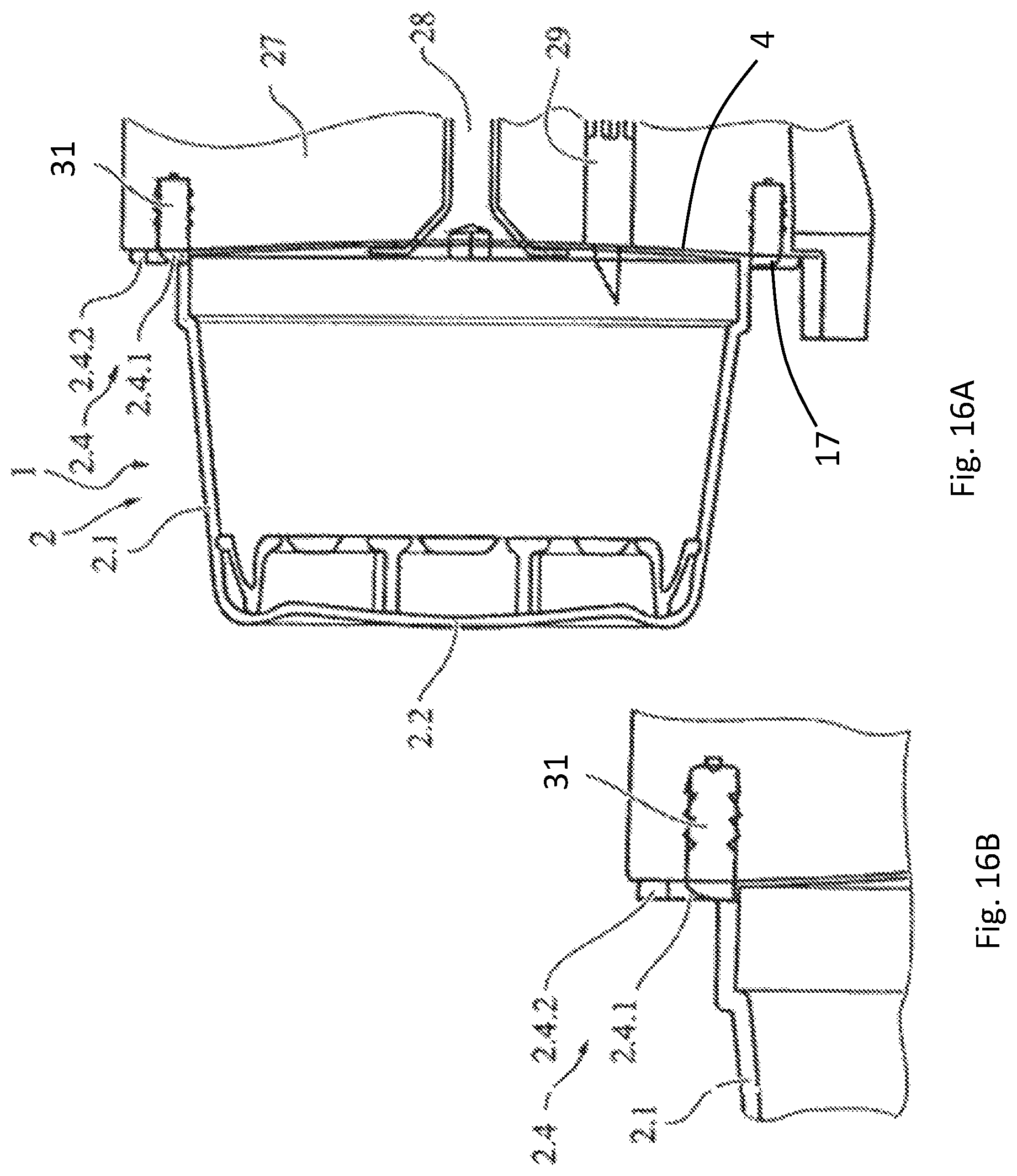
FIGS. 16A and 16B show a portion capsule with a gearwheel placed in the brewing chamber.
FIGS. 17 a-c show different embodiments of the portion capsule according to FIGS. 16A and 16B.
FIG. 18 shows the portion capsule according to the FIGS. 16 A and 16B and FIGS. 17 a-c, when the portion capsule is fit locking with a gearwheel.
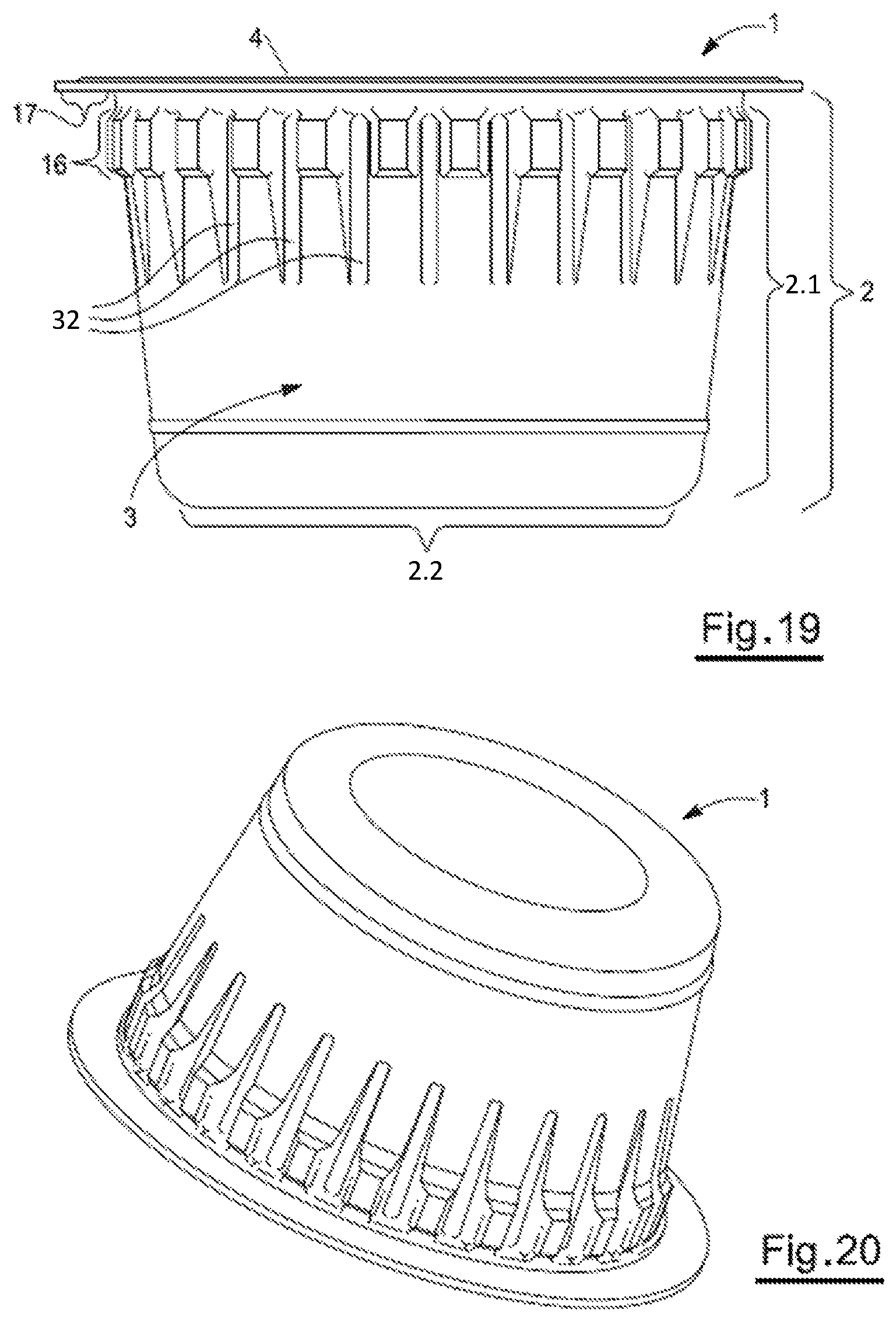
FIGS. 19 and 20 show a schematic view of a portion capsule according to an embodiment of the presented invention.
FIGS. 21 and 22 show two sectional views of the portion capsule according to an embodiment of the presented invention.
DETAILED DESCRIPTION
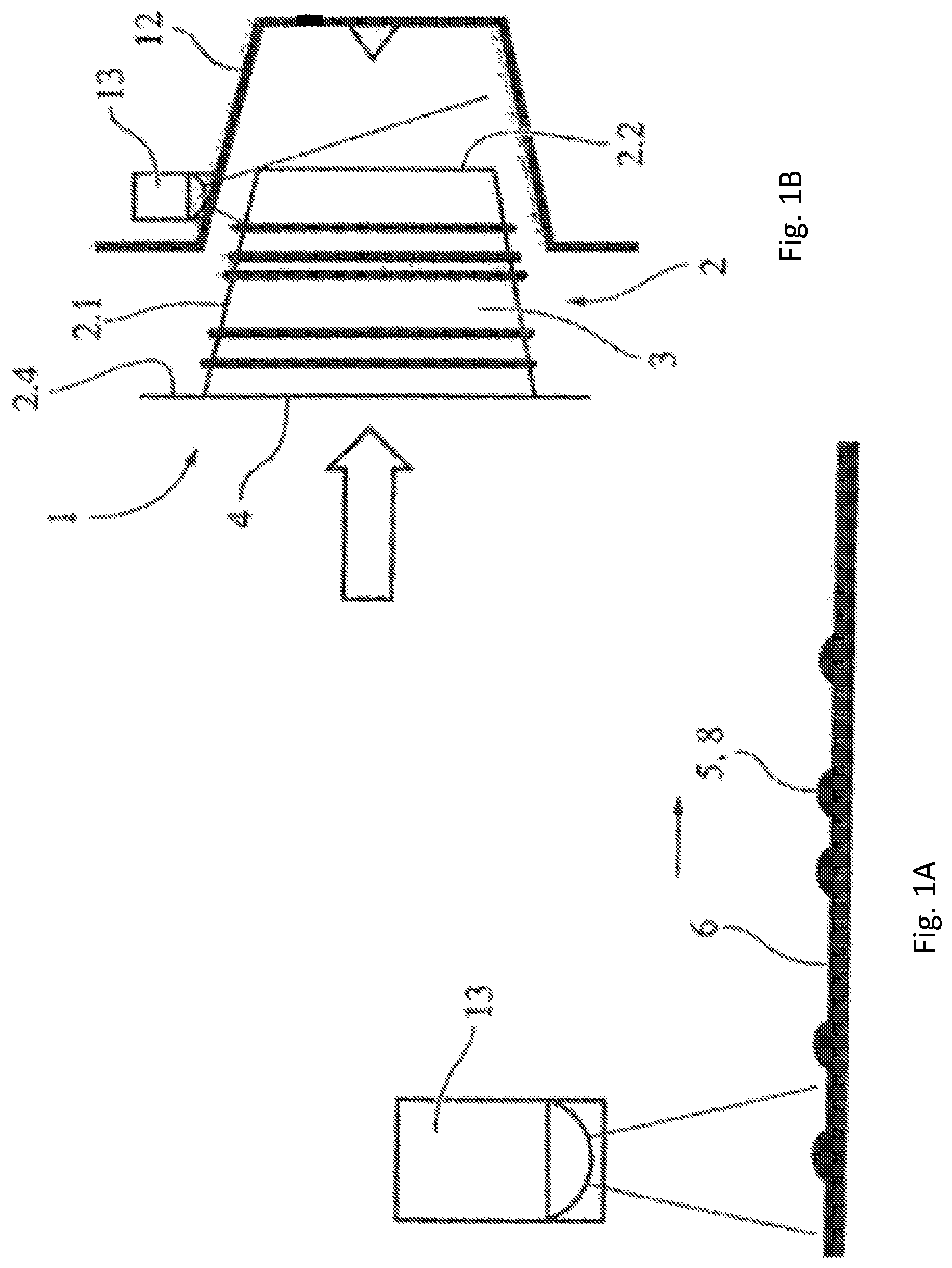
FIGS. 1A and 1B show a portion capsule 1 comprising a base element 2 that has a wall region 2.1 and a bottom area 2.2. The wall region 2.1 and the bottom area 2.2 define a cavity 3, which may include the raw material and perhaps a built-in element. After filling, the cavity 3 is sealed by a membrane 4, which is preferably attached to the edge region 2.4 of the base element using seal or glue. This portion capsule can be inserted into a brewing chamber 12, with a liquid, in particular water, flowing through it. During this process, the raw material is extracted or dissolved and therefore the beverage is produced. According to the invention the portion capsule has only one identifier that allows to determine whether the respective portion capsule goes with the coffee machine's brewing chamber and the parameters for processing are chosen properly. If it is not the case, significant security issues arise. Inserting the wrong portion capsule, for example, endangers the brewing chamber's tightness. In this case hot water can be discharged under high pressure and therefore compromise the user's safety. Otherwise it is also possible that inserting the wrong portion capsule damages the coffee machine. In this example the identifier is represented by several raised areas 8, which differ in reflection properties from the sections between the raised areas. As shown by the arrows the bulges are passed by a mean for detection 13 (here: an optical detector) that is able to differentiate between the unequal sections 5, 6 having different optical properties such as, for example, reflection. Switching between the different sections or the number of bulges represents the identifier. After the identifier has been read out the identifier is compared to a stored reference. If the identifier agrees with the reference, the coffee machine will start operating. Particularly the pump, which is for example responsible for pushing hot water through the brewing chamber, will not start operating, if the identifier does not agree with the reference.
All the remarks concerning the identifier apply to all the examples.
FIGS. 2A and 2B show another embodiment of the portion capsule 1 according to the invention. The portion capsule 1 comprises a base element 2 that has a wall region 2.1 and a bottom area 2.2. Here the portion capsule 1 has a barcode 50 placed in the area of the membrane's 4 top surface. This barcode may be printed by material removal or may be generated by a medium that is integrated in the foil and can be detected optically such as a fluorescence agent. Alternatively, metal rings may be part of the foil or attached to the foil. The barcode's section may be made of a ferromagnetic material. As shown by the arrow 15 the barcode 50 alternatively can be attached to the base element's edge region being averted from the membrane 4. Such a barcode is read out by a detector 13 placed, for example, in the media chute. The barcode represents the identifier according to invention.
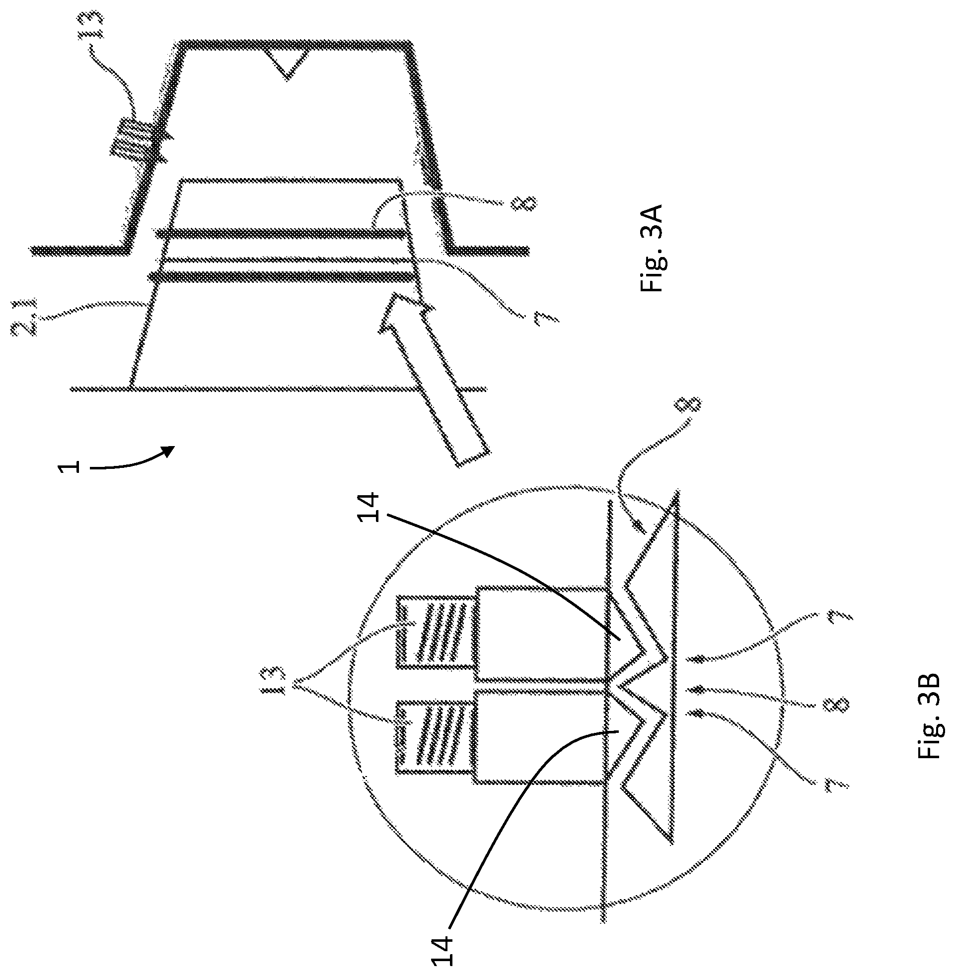
FIGS. 3A and 3B show another embodiment of the portion capsule 1 according to the invention. In the present case the identifier comprises recesses and bulges 7, 8, which result from material removal or reshaping the portion capsule as shown here by the example of the portion capsule's wall 2.1. In the present case, recesses and bulges interact with a means for detection 13, which operates like a key, wherein the coffee machine only start operating, when all elements 14 are placed in the respective recess 7. Therefore, an electric circuit may be changed or especially closed.
FIG. 4 shows an embodiment of the portion capsule being substantially identical to the embodiment illustrated in FIG. 1. As an alternative version of the invention, the figure additionally shows that the unequal sections 5, 6 differing in terms of optical properties can be attached to the cover foil, for example in the form of a barcode.
FIG. 5 shows an embodiment of the portion capsule being substantially identical to the embodiment illustrated in FIG. 3 that includes recesses 7 and bulges 8. Again, the recesses represent the key bit. The coffee machine only will start operating, if the recesses interact with the corresponding bulges and therefore an electric circuit is changed respectively. The placement of such a system is not restricted to the brewing chamber. For instance, the system may be placed in the portion capsule's media chute.
FIG. 6 shows a version of the invention that includes a base element 2 and an electric material forming a surrounding ring 2.3, which preferably has a raised form. The electrically conductive material is scanned by means for detection 13 having electric sliding contacts, which are placed in the media chute and form electric contacts of an electric circuit, while the portion capsule is inserted.
FIG. 7 shows an embodiment of the portion capsule being substantially identical to the embodiment illustrated in FIG. 6, in which it is provided that the ring area has reflective 21 or mat 22 sections, for example in form of a covering, and allows a read-out by means for detection 13 for optical detection, which are placed in the media chute and are part of a control current, while the portion capsule is inserted.
FIG. 8 shows a relative broad and raised ring 2.3 which represents the identifier. The media chute is equipped with a corresponding vacancy that tests whether the portion capsule has the proper identifier. The broad ring is scanned, for example, by means for detection 13 having mechanical sensors, which are placed in the media chute and close the contacts of an electric circuit, while the portions capsule is inserted.
FIG. 9 shows another embodiment of the portion capsule according to the invention. In the present case an electrically conductive coat 10 is integrated in the edge region's back and is scanned by electric sliding contacts, which are placed in the media chute and form electric contacts of an electric circuit, while the portion capsule is inserted.
FIG. 10 shows another embodiment of the portion capsule according to the invention. In the present case the portion capsule has an electrically conductive coat 10 at the bottom area 2.2 such as a conductive varnish layer or an aluminum foil. The coat is scanned by means for detection 13 having electric sliding contacts, which form electric contacts of an electric circuit, while the portion capsule is inserted.
FIG. 11 illustrates a version of the portion capsule having also an electrically conductive coat 10 that is placed on its bottom 2.2 and is identified by a means for detection 13 having a metal sensor, which is placed in the chute and, for example, detects inductively, while the portion capsule is inserted.
The embodiment of the invention shown in FIG. 12 has a build-in element made of metal (here a strainer 19) that is recognized as identifier by a means for detection 13 having a metal detector.
The version of the invention shown in FIG. 13 includes a ferromagnetic material 20 placed at the portion capsule' bottom. The identifier is scanned, by means for detection 13 for example, by a magnet, which is placed in the chute, while the portion capsule is inserted. The ferromagnetic material acts as identifier.
FIG. 14 shows another embodiment which includes a barcode placed in the region of the cover foil. The portion capsule includes a flange 17.
According to the embodiment shown in FIG. 15 a metallic ring 11 is integrated in the wall region 2.1 and closes means for detection 13 having an electric circuit placed in region of the brewing chamber.
FIGS. 16A and 16B show another embodiment of the portion capsule 1 according to the invention. The illustrated portion capsule features a base element 2 that is basically conical-shaped in the present case and has a bottom region 2.2 and a wall region 2.1. It is provided that the base element contains the raw material and, if necessary, build-in elements like a filter as illustrated here. The expert knows that the build-in element may also include other build-in elements. A flange 17/edge region 2.4, which is preferably circular and, for example, may be used for sealing a cover foil 4 to it, is attached to the end of the base element, which is placed opposite to the bottom. The flange/edge region has means for fit locking, friction locking and/or detection 2.4.2 in the outer area (outer circumference). As especially shown in the FIGS. 17a-17c the means for fit locking, friction locking and/or detection 2.4.2 is, in the present case, a gearwheel that is formed by several recesses/bulges evenly arranged in the edge region. Preferably, it is provided that the edge region has a sealing surface 2.4.1, which sealingly interacts with the seal 31 attached to the brewing chamber 27, on the interior side of the gearwheel. The sealing 31 makes sure that the water coming from a water inlet 28 flows through the portion capsule by passing an opening, which has been made by a mandrel 29, than around it.
FIGS. 17a-17c show different embodiments of the means for fit locking, friction locking and/or detection 2.4.2. According to the version shown in FIG. 17a, the gearwheel has forty-five teeth. According to the version shown in FIG. 17b or 17c, the gearwheel has twenty-two or twenty-nine teeth, respectively. The expert knows that the manufactured teeth can be shaped arbitrarily. All FIGS. 17a-17c demonstrate how the portion capsule 1 can be held by a part of the brewing chamber 27 using two holding arms 30. The holding arms interacts with the means for fit locking, friction locking and/or detection 2.4.2. If they are not available, the holding arms will not hold the portion capsule and the portion capsule will not be inserted into the brewing chamber and will fall through it into a dropping box instead. The portion capsule has a base element 2, a wall region 2.1, a bottom area 2.2, a sealing surface 2.4.1, and an edge region 2.4.
FIG. 18 shows the means for fit locking, friction locking and/or detection 2.4.2 along with mean for fit locking 24, which is attached to the coffee machine and is represented by a pinion here. It is provided that the mean for fit locking 24 is placed in the media chute or insertion shaft 26 of an insertion shaft housing 23 having a port for inserting the portion capsule in the coffee machine. The distance between the inner wall 25 of the portion capsule 1 and the mean for fit locking 24 represented by the pinion 24 are designed in such a way that the portion capsule only will pass the port, if the means for fit locking, friction locking and/or detection 2.4.2 is formed complementary to the teeth of the mean for fit locking 24 represented by the pinion. Only in this case the portion capsule rotates the mean for fit locking 24 represented by the pinion 24 while it falls. Both rotating and falling are represented by arrows in the figure. The portion capsule needs the rotation for passing the media chute's port and falling in the intended position afterwards. If the portion capsule has no or wrong mean of fit locking, it will be impossible to place the portion capsule by passing the media chute in the intended position. Additionally or alternatively, it is provided that the mean for fit locking 24 represented by the pinion has a pick-up that detects the rotary movement and transmits it to a control unit. If the rotation at least corresponds a defined rotating element, the control unit will activate, for example, the brewing unit. The expert knows that the portion capsule's border may include means for friction locking that interacts with a mean, for example an edge, and shift it in such a way that the shift is detected and therefore the brewing chamber is activated. The portion capsule 1 has a cover foil 4 and a sealing surface 2.4.1.
The expert moreover knows that a sensor, being for example a camera, which detects the form of the means for fit locking, friction locking and/or detection 2.4.2., may be installed in the media chute. In the present case the form and/or the distance between the teeth may be detected. If the proper portion capsule was inserted, a resulting signal could be transmitted to a control unit, which activates the brewing chamber.
FIG. 19 schematically shows a view of another portion capsule's version according to an embodiment of the present invention. FIG. 20 illustrates the same portion capsule from a different point of view schematically. FIG. 19 shows the front view of the portion capsule. FIG. 20 shows the portion capsule viewed from an angle below. In all figures the portion capsule is labeled with the reference sign 1. The portion capsule substantially has a frustoconically shaped base element 2, which is formed similar to a pot and encloses a cavity 3. The cavity 3 is sealed by a membrane 4. Since the viewing direction of FIG. 19 is essentially parallel to the plane, in which the membrane is located, the membrane is at the upper edge of the portion capsule. In particular, the base element 2 comprises a soft, semi-rigid or rigid plastic material which is deep-drown, preferably. The membrane comprises a foil made of plastic material or aluminum. Preferably the base element has a circumferential mounting flange 17 in the region of the membrane, with the membrane and the mounting flange 17 being firmly bonded, in particular by welding or gluing. Preferably a filter element, which is not specifically depicted in the figures, is placed within the base element 2. For instance, the filter element is made of thermoplastic resin such as, for example, polypropylene. The filter element could also be made of a non-woven material such as, for example, thermoplastic resin. Preferably the filter element divides the cavity 3 in two sections. It is provided that the first section can be filled with a raw material and the second section can be filled with and particularly collect a beverage's extract, which is not shown, during the extractions process. Both sections are not illustrated individually.
The portion capsule is intended for inserting into a brewing chamber or a device for producing a beverage, which is not shown here. In particular such a device for producing a beverage is a coffee machine. The device for producing a beverage could be also a machine that produces a tea drink, a chocolate drink or any other beverage. Preferably an extraction liquid, which is particularly water or hot water, is brought under high pressure into the brewing chamber of the device for producing a beverage. The extraction liquid interacts with the raw material of the beverage in such a way that an extract of a beverage or a beverage is generated. In particular the filter element is utilized as a strainer for the extract of a beverage.
According to the invention, the base element 2 has a wall region 2.1 and a bottom area 2.2. The wall region 2.1 basically ranges from the flange 17 to the bottom region 2.2. Several grooves 32 are placed in the wall region. In particular these grooves are keyways that are integrated in the wall region 2.1 and are facing the cavity 3 and range from the flange 17 to the bottom region 2.2 (i.e. they run perpendicular according to FIG. 19). According to the invention provision is made for the grooves 32 to be extended vertically across the wall region, i.e. they run straight from the flange 17 to the bottom region 2.2, in which it is not necessary that they are extended over the whole length. The grooves are formed according to the invention in such a way that the wall region is reinforced or stiffened due to the grooves 32. Moreover, the plurality of the grooves 32, which are distributed over the wall region 2.1, realize an adhesion between wall region 2.1 and the brewing chamber's wall of the device for producing a beverage after the extraction process. This makes it easier to eject the portion capsule from the brewing chamber automatically. The portion capsule's version represented in FIG. 19 comprises a circumferential border 16 that is placed at the wall region 2.1 ranging from the flange 17 to the bottom area 2.2, namely adjacent to the flange 17 facing towards the bottom area 2.2. The border 16 has an enlarged diameter (parallel to the membrane 4) compared to the wall region's ranging from the border 16 to the bottom area 2.2. It is provided that the border's contour 16 is designed in such a manner that the border's diameter tapers towards the flange 17.
It is provided according to the portion capsule's embodiment, which is represented in FIG. 19 and is in accordance with the invention, that the grooves 32 are placed in the border's region in the first part, partially range from the border 16 to the bottom area 2.2 across the wall region 2.1, in the second part and then finally end. All in all the grooves cover, for example, around 50% of the extension of the wall region 2.1, which ranges from the flange 17 to the bottom area 2.2, wherein one-third of the grooves' extension is placed in the border's region and two-thirds of the grooves' extension is placed in the remaining wall region 2.1 that range from the border 16 to the bottom area 2.2.
A portion capsule 1 according to the invention is shown as sectional view along the portion capsule's extension regarding its height in FIG. 21, i.e. the section's plane is perpendicular to the membrane's main plane. FIG. 22 also shows a portion capsule according to the invention in a sectional view portraying the sectional plane, which is parallel to the membrane's main plane. It is noticeable that the interior of the portion capsule's cavity is shown in FIG. 21. The portion capsule's material or the base element's material is so thin that the implementation of grooves 32 at the exterior shown in FIG. 19 leads to corresponding convexities 34 and impressions at the interior. FIG. 22 particularly illustrates the gearwheel shaped contour 36 resulting from insertion of grooves in the portion capsule's 1 wall region.
* * * * *
References
D00000
D00001
D00002
D00003
D00004
D00005
D00006
D00007
D00008
D00009
D00010
D00011
D00012
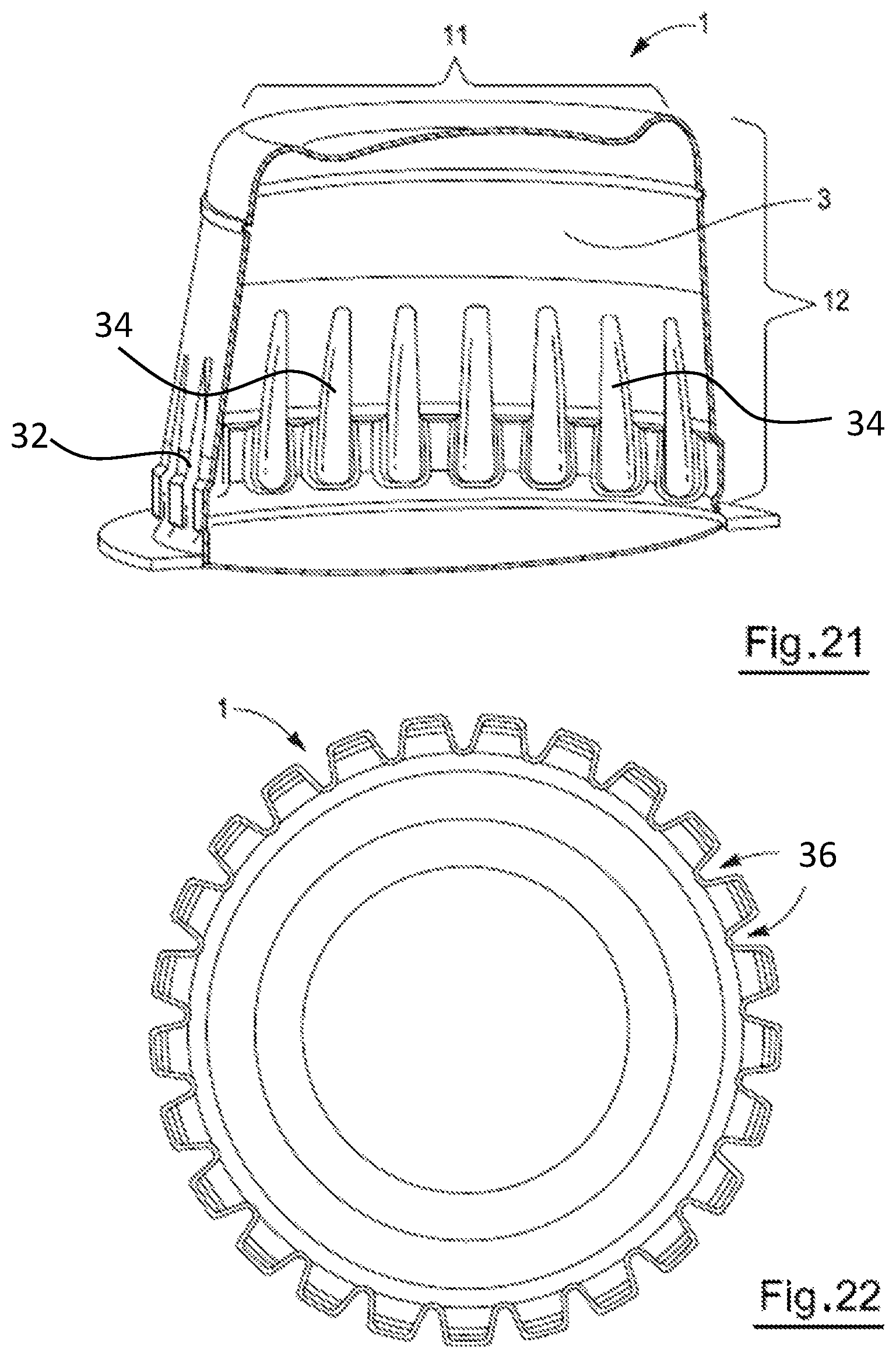
XML
uspto.report is an independent third-party trademark research tool that is not affiliated, endorsed, or sponsored by the United States Patent and Trademark Office (USPTO) or any other governmental organization. The information provided by uspto.report is based on publicly available data at the time of writing and is intended for informational purposes only.
While we strive to provide accurate and up-to-date information, we do not guarantee the accuracy, completeness, reliability, or suitability of the information displayed on this site. The use of this site is at your own risk. Any reliance you place on such information is therefore strictly at your own risk.
All official trademark data, including owner information, should be verified by visiting the official USPTO website at www.uspto.gov. This site is not intended to replace professional legal advice and should not be used as a substitute for consulting with a legal professional who is knowledgeable about trademark law.