Secure unattended network authentication
Kubler , et al. December 8, 2
U.S. patent number 10,860,706 [Application Number 15/830,641] was granted by the patent office on 2020-12-08 for secure unattended network authentication. This patent grant is currently assigned to Hand Held Products, Inc.. The grantee listed for this patent is Hand Held Products, Inc.. Invention is credited to Jonathan D. Fletcher, Joseph J. Kubler, Arthur Millican.


| United States Patent | 10,860,706 |
| Kubler , et al. | December 8, 2020 |
Secure unattended network authentication
Abstract
A system for secure network access by unattended devices is described. The system describes how unattended devices that have encrypted data at rest and/or require secure authentication to an open network may procure the access credentials for authentication and/or decryption. With these access credentials, then the unattended devices may exchange information with and/or receive updates from servers on the network.
| Inventors: | Kubler; Joseph J. (Lafayette, CO), Millican; Arthur (Granite Falls, WA), Fletcher; Jonathan D. (Tekoa, WA) | ||||||||||
|---|---|---|---|---|---|---|---|---|---|---|---|
| Applicant: |
|
||||||||||
| Assignee: | Hand Held Products, Inc. (Fort
Mill, SC) |
||||||||||
| Family ID: | 57146833 | ||||||||||
| Appl. No.: | 15/830,641 | ||||||||||
| Filed: | December 4, 2017 |
Prior Publication Data
| Document Identifier | Publication Date | |
|---|---|---|
| US 20180101675 A1 | Apr 12, 2018 | |
Related U.S. Patent Documents
| Application Number | Filing Date | Patent Number | Issue Date | ||
|---|---|---|---|---|---|
| 14695923 | Apr 24, 2015 | ||||
| Current U.S. Class: | 1/1 |
| Current CPC Class: | G06F 21/44 (20130101); H04L 63/0853 (20130101); G06F 21/42 (20130101); H04L 63/18 (20130101) |
| Current International Class: | H04L 29/06 (20060101); G06F 21/44 (20130101); G06F 21/42 (20130101) |
References Cited [Referenced By]
U.S. Patent Documents
| 6832725 | December 2004 | Gardiner et al. |
| 6976062 | December 2005 | Denby et al. |
| 7128266 | October 2006 | Zhu et al. |
| 7159783 | January 2007 | Walczyk et al. |
| 7270275 | September 2007 | Moreland |
| 7413127 | August 2008 | Ehrhart et al. |
| 7726575 | June 2010 | Wang et al. |
| 8065724 | November 2011 | Waltenberg et al. |
| 8294969 | October 2012 | Plesko |
| 8317105 | November 2012 | Kotlarsky et al. |
| 8322622 | December 2012 | Liu |
| 8366005 | February 2013 | Kotlarsky et al. |
| 8371507 | February 2013 | Haggerty et al. |
| 8376233 | February 2013 | Van Horn et al. |
| 8381979 | February 2013 | Franz |
| 8390909 | March 2013 | Plesko |
| 8408464 | April 2013 | Zhu et al. |
| 8408468 | April 2013 | Horn et al. |
| 8408469 | April 2013 | Good |
| 8424768 | April 2013 | Rueblinger et al. |
| 8448863 | May 2013 | Xian et al. |
| 8457013 | June 2013 | Essinger et al. |
| 8459557 | June 2013 | Havens et al. |
| 8469272 | June 2013 | Kearney |
| 8474712 | July 2013 | Kearney et al. |
| 8479992 | July 2013 | Kotlarsky et al. |
| 8490877 | July 2013 | Kearney |
| 8504505 | August 2013 | Mintah |
| 8517271 | August 2013 | Kotlarsky et al. |
| 8523076 | September 2013 | Good |
| 8528818 | September 2013 | Ehrhart et al. |
| 8544737 | October 2013 | Gomez et al. |
| 8548420 | October 2013 | Grunow et al. |
| 8550335 | October 2013 | Samek et al. |
| 8550354 | October 2013 | Gannon et al. |
| 8550357 | October 2013 | Kearney |
| 8556174 | October 2013 | Kosecki et al. |
| 8556176 | October 2013 | Van Horn et al. |
| 8556177 | October 2013 | Hussey et al. |
| 8559767 | October 2013 | Barber et al. |
| 8561895 | October 2013 | Gomez et al. |
| 8561903 | October 2013 | Sauerwein |
| 8561905 | October 2013 | Edmonds et al. |
| 8565107 | October 2013 | Pease et al. |
| 8571307 | October 2013 | Li et al. |
| 8579200 | November 2013 | Samek et al. |
| 8583924 | November 2013 | Caballero et al. |
| 8584945 | November 2013 | Wang et al. |
| 8587595 | November 2013 | Wang |
| 8587697 | November 2013 | Hussey et al. |
| 8588869 | November 2013 | Sauerwein et al. |
| 8590789 | November 2013 | Nahill et al. |
| 8596539 | December 2013 | Havens et al. |
| 8596542 | December 2013 | Havens et al. |
| 8596543 | December 2013 | Havens et al. |
| 8599271 | December 2013 | Havens et al. |
| 8599957 | December 2013 | Peake et al. |
| 8600158 | December 2013 | Li et al. |
| 8600167 | December 2013 | Showering |
| 8602309 | December 2013 | Longacre et al. |
| 8608053 | December 2013 | Meier et al. |
| 8608071 | December 2013 | Liu et al. |
| 8611309 | December 2013 | Wang et al. |
| 8615487 | December 2013 | Gomez et al. |
| 8621123 | December 2013 | Caballero |
| 8622303 | January 2014 | Meier et al. |
| 8628013 | January 2014 | Ding |
| 8628015 | January 2014 | Wang et al. |
| 8628016 | January 2014 | Winegar |
| 8629926 | January 2014 | Wang |
| 8630491 | January 2014 | Longacre et al. |
| 8635309 | January 2014 | Berthiaume et al. |
| 8636200 | January 2014 | Kearney |
| 8636212 | January 2014 | Nahill et al. |
| 8636215 | January 2014 | Ding et al. |
| 8636224 | January 2014 | Wang |
| 8638806 | January 2014 | Wang et al. |
| 8640958 | February 2014 | Lu et al. |
| 8640960 | February 2014 | Wang et al. |
| 8643717 | February 2014 | Li et al. |
| 8646692 | February 2014 | Meier et al. |
| 8646694 | February 2014 | Wang et al. |
| 8657200 | February 2014 | Ren et al. |
| 8659397 | February 2014 | Vargo et al. |
| 8668149 | March 2014 | Good |
| 8678285 | March 2014 | Kearney |
| 8678286 | March 2014 | Smith et al. |
| 8682077 | March 2014 | Longacre |
| D702237 | April 2014 | Oberpriller et al. |
| 8687282 | April 2014 | Feng et al. |
| 8692927 | April 2014 | Pease et al. |
| 8695880 | April 2014 | Bremer et al. |
| 8698949 | April 2014 | Grunow et al. |
| 8702000 | April 2014 | Barber et al. |
| 8717494 | May 2014 | Gannon |
| 8720783 | May 2014 | Biss et al. |
| 8723804 | May 2014 | Fletcher et al. |
| 8723904 | May 2014 | Marty et al. |
| 8727223 | May 2014 | Wang |
| 8736909 | May 2014 | Sato et al. |
| 8740082 | June 2014 | Wilz |
| 8740085 | June 2014 | Furlong et al. |
| 8746563 | June 2014 | Hennick et al. |
| 8750445 | June 2014 | Peake et al. |
| 8752766 | June 2014 | Xian et al. |
| 8756059 | June 2014 | Braho et al. |
| 8757495 | June 2014 | Qu et al. |
| 8760563 | June 2014 | Koziol et al. |
| 8763909 | July 2014 | Reed et al. |
| 8777108 | July 2014 | Coyle |
| 8777109 | July 2014 | Oberpriller et al. |
| 8779898 | July 2014 | Havens et al. |
| 8781520 | July 2014 | Payne et al. |
| 8783573 | July 2014 | Havens et al. |
| 8789757 | July 2014 | Barten |
| 8789758 | July 2014 | Hawley et al. |
| 8789759 | July 2014 | Xian et al. |
| 8794520 | August 2014 | Wang et al. |
| 8794522 | August 2014 | Ehrhart |
| 8794525 | August 2014 | Amundsen et al. |
| 8794526 | August 2014 | Wang et al. |
| 8798367 | August 2014 | Ellis |
| 8807431 | August 2014 | Wang et al. |
| 8807432 | August 2014 | Van Horn et al. |
| 8820630 | September 2014 | Qu et al. |
| 8822848 | September 2014 | Meagher |
| 8824692 | September 2014 | Sheerin et al. |
| 8824696 | September 2014 | Braho |
| 8842849 | September 2014 | Wahl et al. |
| 8844822 | September 2014 | Kotlarsky et al. |
| 8844823 | September 2014 | Fritz et al. |
| 8849019 | September 2014 | Li et al. |
| D716285 | October 2014 | Chaney et al. |
| 8851383 | October 2014 | Yeakley et al. |
| 8854633 | October 2014 | Laffargue |
| 8866963 | October 2014 | Grunow et al. |
| 8868421 | October 2014 | Braho et al. |
| 8868519 | October 2014 | Maloy et al. |
| 8868802 | October 2014 | Barten |
| 8868803 | October 2014 | Caballero |
| 8870074 | October 2014 | Gannon |
| 8879639 | November 2014 | Sauerwein |
| 8880426 | November 2014 | Smith |
| 8881983 | November 2014 | Havens et al. |
| 8881987 | November 2014 | Wang |
| 8903172 | December 2014 | Smith |
| 8908995 | December 2014 | Benos et al. |
| 8910870 | December 2014 | Li et al. |
| 8910875 | December 2014 | Ren et al. |
| 8914290 | December 2014 | Hendrickson et al. |
| 8914788 | December 2014 | Pettinelli et al. |
| 8915439 | December 2014 | Feng et al. |
| 8915444 | December 2014 | Havens et al. |
| 8916789 | December 2014 | Woodburn |
| 8918250 | December 2014 | Hollifield |
| 8918564 | December 2014 | Caballero |
| 8925818 | January 2015 | Kosecki et al. |
| 8939374 | January 2015 | Jovanovski et al. |
| 8942480 | January 2015 | Ellis |
| 8944313 | February 2015 | Williams et al. |
| 8944327 | February 2015 | Meier et al. |
| 8944332 | February 2015 | Harding et al. |
| 8950678 | February 2015 | Germaine et al. |
| D723560 | March 2015 | Zhou et al. |
| 8967468 | March 2015 | Gomez et al. |
| 8971346 | March 2015 | Sevier |
| 8976030 | March 2015 | Cunningham et al. |
| 8976368 | March 2015 | Akel et al. |
| 8978981 | March 2015 | Guan |
| 8978983 | March 2015 | Bremer et al. |
| 8978984 | March 2015 | Hennick et al. |
| 8985456 | March 2015 | Zhu et al. |
| 8985457 | March 2015 | Soule et al. |
| 8985459 | March 2015 | Kearney et al. |
| 8985461 | March 2015 | Gelay et al. |
| 8988578 | March 2015 | Showering |
| 8988590 | March 2015 | Gillet et al. |
| 8991704 | March 2015 | Hopper et al. |
| 8996194 | March 2015 | Davis et al. |
| 8996384 | March 2015 | Funyak et al. |
| 8998091 | April 2015 | Edmonds et al. |
| 9002641 | April 2015 | Showering |
| 9007368 | April 2015 | Laffargue et al. |
| 9010641 | April 2015 | Qu et al. |
| 9015513 | April 2015 | Murawski et al. |
| 9016576 | April 2015 | Brady et al. |
| D730357 | May 2015 | Fitch et al. |
| 9022288 | May 2015 | Nahill et al. |
| 9030964 | May 2015 | Essinger et al. |
| 9033240 | May 2015 | Smith et al. |
| 9033242 | May 2015 | Gillet et al. |
| 9036054 | May 2015 | Koziol et al. |
| 9037344 | May 2015 | Chamberlin |
| 9038911 | May 2015 | Xian et al. |
| 9038915 | May 2015 | Smith |
| D730901 | June 2015 | Oberpriller et al. |
| D730902 | June 2015 | Fitch et al. |
| D733112 | June 2015 | Chaney et al. |
| 9047098 | June 2015 | Barten |
| 9047359 | June 2015 | Caballero et al. |
| 9047420 | June 2015 | Caballero |
| 9047525 | June 2015 | Barber |
| 9047531 | June 2015 | Showering et al. |
| 9049640 | June 2015 | Wang et al. |
| 9053055 | June 2015 | Caballero |
| 9053378 | June 2015 | Hou et al. |
| 9053380 | June 2015 | Xian et al. |
| 9057641 | June 2015 | Amundsen et al. |
| 9058526 | June 2015 | Powilleit |
| 9061527 | June 2015 | Tobin et al. |
| 9064165 | June 2015 | Havens et al. |
| 9064167 | June 2015 | Xian et al. |
| 9064168 | June 2015 | Todeschini et al. |
| 9064254 | June 2015 | Todeschini et al. |
| 9066032 | June 2015 | Wang |
| 9070032 | June 2015 | Corcoran |
| D734339 | July 2015 | Zhou et al. |
| D734751 | July 2015 | Oberpriller et al. |
| 9076459 | July 2015 | Braho et al. |
| 9079423 | July 2015 | Bouverie et al. |
| 9080856 | July 2015 | Laffargue |
| 9082023 | July 2015 | Feng et al. |
| 9084032 | July 2015 | Rautiola et al. |
| 9087250 | July 2015 | Coyle |
| 9092681 | July 2015 | Havens et al. |
| 9092682 | July 2015 | Wilz et al. |
| 9092683 | July 2015 | Koziol et al. |
| 9093141 | July 2015 | Liu |
| 9098763 | August 2015 | Lu et al. |
| 9104929 | August 2015 | Todeschini |
| 9104934 | August 2015 | Li et al. |
| 9107484 | August 2015 | Chaney |
| 9111159 | August 2015 | Liu et al. |
| 9111166 | August 2015 | Cunningham |
| 9135483 | September 2015 | Liu et al. |
| 9137009 | September 2015 | Gardiner |
| 9141839 | September 2015 | Xian et al. |
| 9147096 | September 2015 | Wang |
| 9148474 | September 2015 | Skvoretz |
| 9158000 | October 2015 | Sauerwein |
| 9158340 | October 2015 | Reed et al. |
| 9158953 | October 2015 | Gillet et al. |
| 9159059 | October 2015 | Daddabbo et al. |
| 9165174 | October 2015 | Huck |
| 9171543 | October 2015 | Emerick et al. |
| 9183425 | November 2015 | Wang |
| 9189669 | November 2015 | Zhu et al. |
| 9195844 | November 2015 | Todeschini et al. |
| 9202458 | December 2015 | Braho et al. |
| 9208366 | December 2015 | Liu |
| 9208367 | December 2015 | Wang |
| 9219836 | December 2015 | Bouverie et al. |
| 9224022 | December 2015 | Ackley et al. |
| 9224024 | December 2015 | Bremer et al. |
| 9224027 | December 2015 | Van Horn et al. |
| D747321 | January 2016 | London et al. |
| 9230140 | January 2016 | Ackley |
| 9235553 | January 2016 | Fitch et al. |
| 9239950 | January 2016 | Fletcher |
| 9245492 | January 2016 | Ackley et al. |
| 9443123 | January 2016 | Hejl |
| 9248640 | February 2016 | Heng |
| 9250652 | February 2016 | London et al. |
| 9250712 | February 2016 | Todeschini |
| 9251411 | February 2016 | Todeschini |
| 9258033 | February 2016 | Showering |
| 9262633 | February 2016 | Todeschini et al. |
| 9262660 | February 2016 | Lu et al. |
| 9262662 | February 2016 | Chen et al. |
| 9269036 | February 2016 | Bremer |
| 9270782 | February 2016 | Hala et al. |
| 9274812 | March 2016 | Doren et al. |
| 9275388 | March 2016 | Havens et al. |
| 9277668 | March 2016 | Feng et al. |
| 9280693 | March 2016 | Feng et al. |
| 9286496 | March 2016 | Smith |
| 9297900 | March 2016 | Jiang |
| 9298964 | March 2016 | Li et al. |
| 9301427 | March 2016 | Feng et al. |
| 9304376 | April 2016 | Anderson |
| 9310609 | April 2016 | Rueblinger et al. |
| 9313377 | April 2016 | Todeschini et al. |
| 9317037 | April 2016 | Byford et al. |
| D757009 | May 2016 | Oberpriller et al. |
| 9342723 | May 2016 | Liu et al. |
| 9342724 | May 2016 | McCloskey |
| 9361882 | June 2016 | Ressler et al. |
| 9365381 | June 2016 | Colonel et al. |
| 9373018 | June 2016 | Colavito et al. |
| 9375945 | June 2016 | Bowles |
| 9378403 | June 2016 | Wang et al. |
| D760719 | July 2016 | Zhou et al. |
| 9360304 | July 2016 | Chang et al. |
| 9383848 | July 2016 | Daghigh |
| 9384374 | July 2016 | Bianconi |
| 9390596 | July 2016 | Todeschini |
| D762604 | August 2016 | Fitch et al. |
| D762647 | August 2016 | Fitch et al. |
| 9411386 | August 2016 | Sauerwein |
| 9412242 | August 2016 | Van Horn et al. |
| 9418269 | August 2016 | Havens et al. |
| 9418270 | August 2016 | Van Volkinburg et al. |
| 9423318 | August 2016 | Lui et al. |
| D766244 | September 2016 | Zhou et al. |
| 9443222 | September 2016 | Singel et al. |
| 9454689 | September 2016 | McCloskey et al. |
| 9464885 | October 2016 | Lloyd et al. |
| 9465967 | October 2016 | Xian et al. |
| 9478113 | October 2016 | Xie et al. |
| 9478983 | October 2016 | Kather et al. |
| D771631 | November 2016 | Fitch et al. |
| 9481186 | November 2016 | Bouverie et al. |
| 9488986 | November 2016 | Solanki |
| 9489782 | November 2016 | Payne et al. |
| 9490540 | November 2016 | Davies et al. |
| 9491729 | November 2016 | Rautiola et al. |
| 9497092 | November 2016 | Gomez et al. |
| 9507974 | November 2016 | Todeschini |
| 9519814 | December 2016 | Cudzilo |
| 9521331 | December 2016 | Bessettes et al. |
| 9530038 | December 2016 | Xian et al. |
| D777166 | January 2017 | Bidwell et al. |
| 9558386 | January 2017 | Yeakley |
| 9572901 | February 2017 | Todeschini |
| 9606581 | March 2017 | Howe et al. |
| D783601 | April 2017 | Schulte et al. |
| D785617 | May 2017 | Bidwell et al. |
| D785636 | May 2017 | Oberpriller et al. |
| 9646189 | May 2017 | Lu et al. |
| 9646191 | May 2017 | Unemyr et al. |
| 9652648 | May 2017 | Ackley et al. |
| 9652653 | May 2017 | Todeschini et al. |
| 9656487 | May 2017 | Ho et al. |
| 9659198 | May 2017 | Giordano et al. |
| D790505 | June 2017 | Vargo et al. |
| D790546 | June 2017 | Zhou et al. |
| D790553 | June 2017 | Fitch et al. |
| 9680282 | June 2017 | Hanenburg |
| 9697401 | July 2017 | Feng et al. |
| 9701140 | July 2017 | Alaganchetty et al. |
| 2002/0063035 | May 2002 | Blad |
| 2005/0109841 | May 2005 | Ryan |
| 2005/0246470 | November 2005 | Brenner |
| 2006/0149323 | July 2006 | Merry |
| 2007/0063048 | March 2007 | Havens et al. |
| 2007/0101403 | May 2007 | Kubler |
| 2008/0014867 | January 2008 | Finn |
| 2008/0168544 | July 2008 | von Krogh |
| 2009/0134221 | May 2009 | Zhu et al. |
| 2010/0177076 | July 2010 | Essinger et al. |
| 2010/0177080 | July 2010 | Essinger et al. |
| 2010/0177707 | July 2010 | Essinger et al. |
| 2010/0177749 | July 2010 | Essinger et al. |
| 2011/0169999 | July 2011 | Grunow et al. |
| 2011/0202554 | August 2011 | Powilleit et al. |
| 2011/0246773 | October 2011 | Sidle |
| 2011/0249394 | October 2011 | Nielsen |
| 2012/0111946 | May 2012 | Golant |
| 2012/0168512 | July 2012 | Kotlarsky et al. |
| 2012/0193423 | August 2012 | Samek |
| 2012/0203647 | August 2012 | Smith |
| 2012/0223141 | September 2012 | Good et al. |
| 2013/0043312 | February 2013 | Van Horn |
| 2013/0075168 | March 2013 | Amundsen et al. |
| 2013/0175341 | July 2013 | Kearney et al. |
| 2013/0175343 | July 2013 | Good |
| 2013/0257744 | October 2013 | Daghigh et al. |
| 2013/0257759 | October 2013 | Daghigh |
| 2013/0270346 | October 2013 | Xian et al. |
| 2013/0287258 | October 2013 | Kearney |
| 2013/0292475 | November 2013 | Kotlarsky et al. |
| 2013/0292477 | November 2013 | Hennick et al. |
| 2013/0293539 | November 2013 | Hunt et al. |
| 2013/0293540 | November 2013 | Laffargue et al. |
| 2013/0306728 | November 2013 | Thuries et al. |
| 2013/0306731 | November 2013 | Pedraro |
| 2013/0307964 | November 2013 | Bremer et al. |
| 2013/0308625 | November 2013 | Park et al. |
| 2013/0313324 | November 2013 | Koziol et al. |
| 2013/0332524 | December 2013 | Fiala et al. |
| 2013/0342717 | December 2013 | Havens et al. |
| 2014/0001267 | January 2014 | Giordano et al. |
| 2014/0002828 | January 2014 | Laffargue et al. |
| 2014/0008439 | January 2014 | Wang |
| 2014/0025584 | January 2014 | Liu et al. |
| 2014/0100813 | January 2014 | Showering |
| 2014/0034734 | February 2014 | Sauerwein |
| 2014/0036848 | February 2014 | Pease et al. |
| 2014/0039693 | February 2014 | Havens et al. |
| 2014/0049120 | February 2014 | Kohtz et al. |
| 2014/0049635 | February 2014 | Laffargue et al. |
| 2014/0061306 | March 2014 | Wu et al. |
| 2014/0063289 | March 2014 | Hussey et al. |
| 2014/0066136 | March 2014 | Sauerwein et al. |
| 2014/0067692 | March 2014 | Ye et al. |
| 2014/0070005 | March 2014 | Nahill et al. |
| 2014/0071840 | March 2014 | Venancio |
| 2014/0074746 | March 2014 | Wang |
| 2014/0076974 | March 2014 | Havens et al. |
| 2014/0078341 | March 2014 | Havens et al. |
| 2014/0078342 | March 2014 | Li et al. |
| 2014/0078345 | March 2014 | Showering |
| 2014/0098792 | April 2014 | Wang et al. |
| 2014/0100774 | April 2014 | Showering |
| 2014/0103115 | April 2014 | Meier et al. |
| 2014/0104413 | April 2014 | McCloskey et al. |
| 2014/0104414 | April 2014 | McCloskey et al. |
| 2014/0104416 | April 2014 | Giordano et al. |
| 2014/0106725 | April 2014 | Sauerwein |
| 2014/0108010 | April 2014 | Maltseff et al. |
| 2014/0108402 | April 2014 | Gomez et al. |
| 2014/0108682 | April 2014 | Caballero |
| 2014/0110485 | April 2014 | Toa et al. |
| 2014/0114530 | April 2014 | Fitch et al. |
| 2014/0121438 | May 2014 | Long et al. |
| 2014/0121445 | May 2014 | Fontenot et al. |
| 2014/0124577 | May 2014 | Wang et al. |
| 2014/0124579 | May 2014 | Ding |
| 2014/0125842 | May 2014 | Winegar |
| 2014/0125853 | May 2014 | Wang |
| 2014/0125999 | May 2014 | Longacre et al. |
| 2014/0129378 | May 2014 | Richardson |
| 2014/0131438 | May 2014 | Kearney |
| 2014/0131441 | May 2014 | Nahill et al. |
| 2014/0131443 | May 2014 | Smith |
| 2014/0131444 | May 2014 | Wang |
| 2014/0131445 | May 2014 | Ding et al. |
| 2014/0133379 | May 2014 | Wang et al. |
| 2014/0136208 | May 2014 | Maltseff et al. |
| 2014/0140585 | May 2014 | Wang |
| 2014/0151453 | June 2014 | Meier et al. |
| 2014/0152882 | June 2014 | Samek et al. |
| 2014/0158770 | June 2014 | Sevier et al. |
| 2014/0159869 | June 2014 | Zumsteg et al. |
| 2014/0166755 | June 2014 | Liu et al. |
| 2014/0166757 | June 2014 | Smith |
| 2014/0166759 | June 2014 | Liu et al. |
| 2014/0168787 | June 2014 | Wang et al. |
| 2014/0175165 | June 2014 | Havens et al. |
| 2014/0175172 | June 2014 | Jovanovski et al. |
| 2014/0181955 | June 2014 | Rosati |
| 2014/0191913 | July 2014 | Ge et al. |
| 2014/0197239 | July 2014 | Havens et al. |
| 2014/0197304 | July 2014 | Feng et al. |
| 2014/0204268 | July 2014 | Grunow et al. |
| 2014/0214631 | July 2014 | Hansen |
| 2014/0217166 | August 2014 | Berthiaume et al. |
| 2014/0217180 | August 2014 | Liu |
| 2014/0231500 | August 2014 | Ehrhart et al. |
| 2014/0245021 | August 2014 | Nagai |
| 2014/0247315 | September 2014 | Marty et al. |
| 2014/0263493 | September 2014 | Amurgis et al. |
| 2014/0263645 | September 2014 | Smith et al. |
| 2014/0270196 | September 2014 | Braho et al. |
| 2014/0270229 | September 2014 | Braho |
| 2014/0278387 | September 2014 | DiGregorio |
| 2014/0282210 | September 2014 | Bianconi |
| 2014/0288933 | September 2014 | Braho et al. |
| 2014/0297058 | October 2014 | Barker et al. |
| 2014/0299665 | October 2014 | Barber et al. |
| 2014/0312121 | October 2014 | Lu et al. |
| 2014/0319221 | October 2014 | Oberpriller et al. |
| 2014/0326787 | November 2014 | Barten |
| 2014/0332590 | November 2014 | Wang et al. |
| 2014/0351317 | November 2014 | Smith et al. |
| 2014/0353373 | December 2014 | Van et al. |
| 2014/0361073 | December 2014 | Qu et al. |
| 2014/0362184 | December 2014 | Jovanovski et al. |
| 2014/0363015 | December 2014 | Braho |
| 2014/0369511 | December 2014 | Sheerin et al. |
| 2014/0374483 | December 2014 | Lu |
| 2014/0374485 | December 2014 | Xian et al. |
| 2015/0001301 | January 2015 | Ouyang |
| 2015/0009338 | January 2015 | Laffargue et al. |
| 2015/0014416 | January 2015 | Kotlarsky et al. |
| 2015/0021397 | January 2015 | Rueblinger et al. |
| 2015/0028102 | January 2015 | Ren et al. |
| 2015/0028104 | January 2015 | Ma et al. |
| 2015/0029002 | January 2015 | Yeakley et al. |
| 2015/0032709 | January 2015 | Maloy et al. |
| 2015/0039309 | February 2015 | Braho et al. |
| 2015/0040378 | February 2015 | Saber et al. |
| 2015/0044964 | February 2015 | Khan |
| 2015/0048168 | February 2015 | Fritz et al. |
| 2015/0049347 | February 2015 | Laffargue et al. |
| 2015/0051992 | February 2015 | Smith |
| 2015/0053766 | February 2015 | Havens et al. |
| 2015/0053769 | February 2015 | Thuries et al. |
| 2015/0062366 | March 2015 | Liu et al. |
| 2015/0063215 | March 2015 | Wang |
| 2015/0069130 | March 2015 | Gannon |
| 2015/0071818 | March 2015 | Scheuren et al. |
| 2015/0083800 | March 2015 | Li et al. |
| 2015/0088522 | March 2015 | Hendrickson et al. |
| 2015/0096872 | April 2015 | Woodburn |
| 2015/0099557 | April 2015 | Pettinelli et al. |
| 2015/0100196 | April 2015 | Hollifield |
| 2015/0115035 | April 2015 | Meier et al. |
| 2015/0126110 | May 2015 | Ashley |
| 2015/0127791 | May 2015 | Kosecki et al. |
| 2015/0128116 | May 2015 | Chen et al. |
| 2015/0129659 | May 2015 | Feng et al. |
| 2015/0133047 | May 2015 | Smith et al. |
| 2015/0134470 | May 2015 | Hejl et al. |
| 2015/0136851 | May 2015 | Harding et al. |
| 2015/0142492 | May 2015 | Kumar |
| 2015/0144692 | May 2015 | Hejl |
| 2015/0144698 | May 2015 | Teng et al. |
| 2015/0149946 | May 2015 | Benos et al. |
| 2015/0161415 | June 2015 | Kreft |
| 2015/0161429 | June 2015 | Xian |
| 2015/0169925 | June 2015 | Chen et al. |
| 2015/0169929 | June 2015 | Williams et al. |
| 2015/0186703 | July 2015 | Chen et al. |
| 2015/0188891 | July 2015 | Grange |
| 2015/0193644 | July 2015 | Kearney et al. |
| 2015/0199957 | July 2015 | Funyak et al. |
| 2015/0204671 | July 2015 | Showering |
| 2015/0210199 | July 2015 | Payne |
| 2015/0213433 | July 2015 | Khan |
| 2015/0220753 | August 2015 | Zhu et al. |
| 2015/0254485 | September 2015 | Feng et al. |
| 2015/0286252 | October 2015 | Barone |
| 2015/0303993 | October 2015 | Showering |
| 2015/0310243 | October 2015 | Ackley |
| 2015/0310389 | October 2015 | Crimm et al. |
| 2015/0327012 | November 2015 | Bian et al. |
| 2016/0014251 | January 2016 | Hejl |
| 2016/0040982 | February 2016 | Li et al. |
| 2016/0042241 | February 2016 | Todeschini |
| 2016/0048461 | February 2016 | Marinelli |
| 2016/0057230 | February 2016 | Todeschini et al. |
| 2016/0062473 | March 2016 | Bouchat et al. |
| 2016/0092805 | March 2016 | Geisler et al. |
| 2016/0101936 | April 2016 | Chamberlin |
| 2016/0102975 | April 2016 | McCloskey et al. |
| 2016/0104019 | April 2016 | Todeschini et al. |
| 2016/0104274 | April 2016 | Jovanovski et al. |
| 2016/0109219 | April 2016 | Ackley et al. |
| 2016/0109220 | April 2016 | Laffargue |
| 2016/0109224 | April 2016 | Thuries et al. |
| 2016/0112631 | April 2016 | Ackley et al. |
| 2016/0112643 | April 2016 | Laffargue et al. |
| 2016/0117627 | April 2016 | Raj et al. |
| 2016/0124516 | May 2016 | Schoon et al. |
| 2016/0125217 | May 2016 | Todeschini |
| 2016/0125342 | May 2016 | Miller et al. |
| 2016/0133253 | May 2016 | Braho et al. |
| 2016/0171597 | June 2016 | Todeschini |
| 2016/0171666 | June 2016 | McCloskey |
| 2016/0171720 | June 2016 | Todeschini |
| 2016/0171775 | June 2016 | Todeschini et al. |
| 2016/0171777 | June 2016 | Todeschini et al. |
| 2016/0174674 | June 2016 | Oberpriller et al. |
| 2016/0178479 | June 2016 | Goldsmith |
| 2016/0178685 | June 2016 | Young et al. |
| 2016/0178707 | June 2016 | Young et al. |
| 2016/0179132 | June 2016 | Harr et al. |
| 2016/0179143 | June 2016 | Bidwell et al. |
| 2016/0179368 | June 2016 | Roeder |
| 2016/0179378 | June 2016 | Kent et al. |
| 2016/0180130 | June 2016 | Bremer |
| 2016/0180133 | June 2016 | Oberpriller et al. |
| 2016/0180136 | June 2016 | Meier et al. |
| 2016/0180594 | June 2016 | Todeschini |
| 2016/0180663 | June 2016 | McMahan et al. |
| 2016/0180678 | June 2016 | Ackley et al. |
| 2016/0180713 | June 2016 | Bernhardt et al. |
| 2016/0185136 | June 2016 | Ng et al. |
| 2016/0185291 | June 2016 | Chamberlin |
| 2016/0186926 | June 2016 | Oberpriller et al. |
| 2016/0188861 | June 2016 | Todeschini |
| 2016/0188939 | June 2016 | Sailors et al. |
| 2016/0188940 | June 2016 | Lu et al. |
| 2016/0188941 | June 2016 | Todeschini et al. |
| 2016/0188942 | June 2016 | Good et al. |
| 2016/0188943 | June 2016 | Linwood |
| 2016/0188944 | June 2016 | Wilz et al. |
| 2016/0189076 | June 2016 | Mellott et al. |
| 2016/0189087 | June 2016 | Morton et al. |
| 2016/0189088 | June 2016 | Percorari et al. |
| 2016/0189092 | June 2016 | George et al. |
| 2016/0189284 | June 2016 | Mellott et al. |
| 2016/0189288 | June 2016 | Todeschini |
| 2016/0189366 | June 2016 | Chamberlin et al. |
| 2016/0189443 | June 2016 | Smith |
| 2016/0189447 | June 2016 | Valenzuela |
| 2016/0189489 | June 2016 | Au et al. |
| 2016/0191684 | June 2016 | DiPiazza et al. |
| 2016/0192051 | June 2016 | DiPiazza et al. |
| 2016/0125873 | July 2016 | Braho et al. |
| 2016/0202951 | July 2016 | Pike et al. |
| 2016/0202958 | July 2016 | Zabel et al. |
| 2016/0202959 | July 2016 | Doubleday et al. |
| 2016/0203021 | July 2016 | Pike et al. |
| 2016/0203429 | July 2016 | Mellott et al. |
| 2016/0203797 | July 2016 | Pike et al. |
| 2016/0203820 | July 2016 | Zabel et al. |
| 2016/0204623 | July 2016 | Haggert et al. |
| 2016/0204636 | July 2016 | Allen et al. |
| 2016/0204638 | July 2016 | Miraglia et al. |
| 2016/0316190 | July 2016 | McCloskey et al. |
| 2016/0227912 | August 2016 | Oberpriller et al. |
| 2016/0232891 | August 2016 | Pecorari |
| 2016/0239657 | August 2016 | Loughlin-McHugh |
| 2016/0253660 | September 2016 | D'Alisa |
| 2016/0292477 | October 2016 | Bidwell |
| 2016/0294779 | October 2016 | Yeakley et al. |
| 2016/0306769 | October 2016 | Kohtz et al. |
| 2016/0314276 | October 2016 | Sewell et al. |
| 2016/0314294 | October 2016 | Kubler et al. |
| 2016/0323310 | November 2016 | Todeschini et al. |
| 2016/0325677 | November 2016 | Fitch et al. |
| 2016/0327614 | November 2016 | Young et al. |
| 2016/0327930 | November 2016 | Charpentier et al. |
| 2016/0328762 | November 2016 | Pape |
| 2016/0330218 | November 2016 | Hussey et al. |
| 2016/0343163 | November 2016 | Venkatesha et al. |
| 2016/0343176 | November 2016 | Ackley |
| 2016/0364914 | December 2016 | Todeschini |
| 2016/0370220 | December 2016 | Ackley et al. |
| 2016/0372282 | December 2016 | Bandringa |
| 2016/0373847 | December 2016 | Vargo et al. |
| 2016/0377414 | December 2016 | Thuries et al. |
| 2016/0377417 | December 2016 | Jovanovski et al. |
| 2017/0010141 | January 2017 | Ackley |
| 2017/0010328 | January 2017 | Mullen et al. |
| 2017/0010780 | January 2017 | Waldron et al. |
| 2017/0016714 | January 2017 | Laffargue et al. |
| 2017/0018094 | January 2017 | Todeschini |
| 2017/0046603 | February 2017 | Lee et al. |
| 2017/0047864 | February 2017 | Stang et al. |
| 2017/0053146 | February 2017 | Liu et al. |
| 2017/0053147 | February 2017 | Geramine et al. |
| 2017/0053647 | February 2017 | Nichols et al. |
| 2017/0055606 | March 2017 | Xu et al. |
| 2017/0060316 | March 2017 | Larson |
| 2017/0061961 | March 2017 | Nichols et al. |
| 2017/0064634 | March 2017 | Van Horn et al. |
| 2017/0083730 | March 2017 | Feng et al. |
| 2017/0091502 | March 2017 | Furlong et al. |
| 2017/0091706 | March 2017 | Lloyd et al. |
| 2017/0091741 | March 2017 | Todeschini |
| 2017/0091904 | March 2017 | Ventress |
| 2017/0092908 | March 2017 | Chaney |
| 2017/0094238 | March 2017 | Germaine et al. |
| 2017/0098947 | April 2017 | Wolski |
| 2017/0100949 | April 2017 | Celinder et al. |
| 2017/0108838 | April 2017 | Todeschinie et al. |
| 2017/0108895 | April 2017 | Chamberlin et al. |
| 2017/0118355 | April 2017 | Wong et al. |
| 2017/0123598 | May 2017 | Phan et al. |
| 2017/0124369 | May 2017 | Rueblinger et al. |
| 2017/0124396 | May 2017 | Todeschini et al. |
| 2017/0124687 | May 2017 | McCloskey et al. |
| 2017/0126873 | May 2017 | McGary et al. |
| 2017/0126904 | May 2017 | d'Armancourt et al. |
| 2017/0139012 | May 2017 | Smith |
| 2017/0140329 | May 2017 | Bernhardt et al. |
| 2017/0140731 | May 2017 | Smith |
| 2017/0147847 | May 2017 | Berggren et al. |
| 2017/0150124 | May 2017 | Thuries |
| 2017/0169198 | June 2017 | Nichols |
| 2017/0171035 | June 2017 | Lu et al. |
| 2017/0171703 | June 2017 | Maheswaranathan |
| 2017/0171803 | June 2017 | Maheswaranathan |
| 2017/0180359 | June 2017 | Wolski et al. |
| 2017/0180577 | June 2017 | Nguon et al. |
| 2017/0181299 | June 2017 | Shi et al. |
| 2017/0190192 | July 2017 | Delario et al. |
| 2017/0193432 | July 2017 | Bernhardt |
| 2017/0193461 | July 2017 | Jonas et al. |
| 2017/0193727 | July 2017 | Van Horn et al. |
| 2017/0200108 | July 2017 | Au et al. |
| 2017/0200275 | July 2017 | McCloskey et al. |
| 2013/173985 | Nov 2013 | WO | |||
| 2013163789 | Nov 2013 | WO | |||
| 2014/110495 | Jul 2014 | WO | |||
Other References
|
NPL Search (Google Scholar) (Year: 2020). cited by examiner . Advisory Action (PTOL-303) dated May 19, 2017 for U.S. Appl. No. 14/695,923. cited by applicant . Final Rejection dated Feb. 8, 2017 for U.S. Appl. No. 14/695,923. cited by applicant . Final Rejection dated Jul. 26, 2018 for U.S. Appl. No. 14/695,923. cited by applicant . Non-Final Rejection dated Aug. 11, 2016 for U.S. Appl. No. 14/695,923. cited by applicant . Non-Final Rejection dated Jul. 3, 2017 for U.S. Appl. No. 14/695,923. cited by applicant . U.S. Patent Application for a Laser Scanning Module Employing an Elastomeric U-Hinge Based Laser Scanning Assembly, filed Feb. 7, 2012 (Feng et al.), U.S. Appl. No. 13/367,978. cited by applicant . U.S. Patent Application for Multifunction Point of Sale Apparatus With Optical Signature Capture filed Jul. 30, 2014 (Good et al.); 37 pages, U.S. Appl. No. 14/446,391. cited by applicant . U.S. Patent Application for Multipurpose Optical Reader, filed May 14, 2014 (Jovanovski et al.); 59 pages, U.S. Appl. No. 14/277,337. cited by applicant . U.S. Patent Application for Terminal Having Illumination and Focus Control filed May 21, 2014 (Liu et al.); 31 pages, U.S. Appl. No. 14/283,282. cited by applicant . U.S. Patent Application Reading Apparatus Having Partial Frame Operating Mode filed Apr. 11, 2014, (Deng et al.), U.S. Appl. No. 14/250,923. cited by applicant . Applicant Initiated Interview Summary (PTOL-413) dated Mar. 6, 2017 for U.S. Appl. No. 14/695,923. cited by applicant. |
Primary Examiner: Rahman; Mahfuzur
Assistant Examiner: Cruz-Franqui; Richard W
Attorney, Agent or Firm: Alston & Bird LLP
Claims
The invention claimed is:
1. A method of authenticating a client device to a server, the method comprising: receiving, at a secure credential device, a request for an access credential from the client device over a first communication channel, wherein the secure credential device comprises one or more tamper detection features or tamper resistant features; wherein the client device is plugged into the secure credential device, wherein the access credential is configured to facilitate authentication of the client device to the server to exchange information with the server, and wherein the secure credential device comprises a second communication channel configured to communicatively couple the secure credential device to a remote token server via a wide area network; sending the request for the access credential from the secure credential device to the remote token server using the second communication channel; exchanging a pairing credential between the secure credential device and the remote token server, wherein the pairing credential is configured to authenticate the secure credential device to the remote token server; in response to the remote token server authenticating the secure credential device, automatically receiving the access credential from the remote token server at the secure credential device, wherein the remote token server generates the access credential each time the client device initiates communication with the server; in response to the secure credential device receiving the access credential, sending the access credential from the secure credential device to the client device over the first communication channel; sending the access credential to the server for validation, the server comprising a server communication interface configured to communicatively couple the client device and the server; and in response to the server validating the access credential, exchanging information between the client device and the server using the server communication interface.
2. The method of claim 1, wherein the client device comprises a mobile device.
3. The method of claim 1, wherein the secure credential device comprises a docking station for the client device.
4. The method of claim 1, wherein receiving, at the secure credential device, the request for the access credential takes place when the client device and the secure credential device are unattended.
5. The method of claim 1, wherein sending the access credential to the server takes place when the client device and the secure credential device are unattended.
6. The method of claim 1, wherein exchanging information between the client device and the server takes place when the client device and the secure credential device are unattended.
7. The method of claim 1, further comprising storing the access credential in memory housed in the secure credential device for future use.
8. The method of claim 1, wherein the access credential is initially provisioned in memory housed in the secure credential device.
9. The method of claim 1, wherein the secure credential device is fixed in location or non-moveable.
10. The method of claim 1, wherein the one or more tamper detection features comprises features configured to detect one or more of: ultraviolet fluorescent chemicals, varying temperature, varying clocking information, varying voltage, and varying electrical signals.
11. The method of claim 1, wherein the one or more tamper resistant features comprises a potted material configured to destroy one or more components of the secure credential device.
12. The method of claim 1, wherein exchanging information between the client device and the server comprises exchanging customer data between the client device and the server.
13. The method of claim 1, wherein exchanging information between the client device and the server comprises the client device receiving an update from the server.
14. A method of authenticating a mobile device to a remote server, the method comprising: receiving a first request for an access credential from the mobile device via a secure credential device, the secure credential device comprising a first communication interface configured to communicatively couple the mobile device and the secure credential device and a second communication interface configured to communicatively couple the secure credential device and a remote token server via a wide area network, wherein the secure credential device comprises one or more tamper detection features or tamper resistant features; wherein the access credential is configured to facilitate authentication of the mobile device to the remote server to exchange information with the remote server, and wherein the secure credential device is internal to the mobile device; sending a second request for the access credential from the secure credential device to the remote token server using the second communication interface; exchanging a pairing credential between the secure credential device and the remote token server, wherein the pairing credential is configured to authenticate the secure credential device to the remote token server; in response to the remote token server authenticating the secure credential device, automatically receiving the access credential from the remote token server at the secure credential device, wherein the remote token server generates the access credential each time the mobile device initiates communication with the remote server using the second communication interface; sending the access credential from the secure credential device to the mobile device using the first communication interface; wherein the remote server comprises a third communication interface configured to communicatively couple the mobile device and the remote server, and wherein the mobile device is configured to send the access credential to the remote server for validation using the third communication interface; and in response to the remote server validating the access credential, exchanging information between the remote server and the mobile device using the third communication interface, the information comprising customer data and updates.
15. The method of claim 14, wherein one or more of: receiving the first request for the access credential from the mobile device, sending the second request for the access credential from the secure credential device to the remote token server, exchanging the pairing credential between the secure credential device and the remote token server, receiving the access credential from the remote token server at the secure credential device and sending the access credential from the secure credential device to the mobile device, takes place when the mobile device and the secure credential device are unattended.
16. The method of claim 14, wherein exchanging information between the remote server and the mobile device takes place when the mobile device and the secure credential device are unattended.
17. A system for authenticating a mobile device to a remote server, the system comprising: a secure credential device in communication with the mobile device, the secure credential device comprising a first communication interface configured to communicatively couple the mobile device and the secure credential device, wherein the secure credential device is configured to receive a first request for an access credential from the mobile device using the first communication interface, the access credential is configured to facilitate authentication of the mobile device to a remote server to exchange information with the remote server when the mobile device is unattended; wherein the secure credential device comprises one or more tamper detection features or tamper resistant features; a remote token server configured to provide the access credential to the secure credential device, the secure credential device comprising a second communication interface configured to communicatively couple the secure credential device and the remote token server via a wide area network, wherein the secure credential device is configured to send a second request for the access credential to the remote token server using the second communication interface, wherein to receive the access credential from the remote token server using the second communication interface, the remote token server and the secure credential device are configured to exchange a pairing credential to authenticate the secure credential device, wherein the remote token server is configured to: generate the access credential each time the mobile device initiates communication with the remote server; and send the access credential to the secure credential device when the remote token server authenticates the secure credential device, and wherein the secure credential device is configured to send the access credential to the mobile device using the first communication interface after having received the access credential from the remote token server; and the remote server, wherein the remote server is configured to exchange information with the mobile device when the mobile device is unattended, the remote server comprises a third communication interface configured to communicatively couple the mobile device and the remote server, wherein the mobile device is configured to send the access credential to the remote server using the third communication interface when the mobile device is unattended, the mobile device having received the access credential from the secure credential device, wherein the remote server and the mobile device are configured to exchange information using the third communication interface when the mobile device is unattended and in response to the remote server validating the access credential, and wherein the information comprises customer data and updates.
18. The system of claim 17, wherein the secure credential device further comprises a memory for storing the access credential for future use.
19. The system of claim 18, wherein exchanging information between the client device and the remote server comprises the mobile device receiving an update from the remote server.
Description
CROSS-REFERENCE TO RELATED APPLICATIONS
The present application claims the benefit of U.S. patent application Ser. No. 14/695,923, filed on Apr. 24, 2015 and published as U.S. Pub. No. 2016/0314294 on Oct. 27, 2016. The foregoing patent application and patent publication are each hereby incorporated by reference their entirety.
FIELD OF THE INVENTION
The present invention relates to secure network access by unattended client devices.
BACKGROUND
Technological advances have made possible an ever-increasing number of different hardware electronic devices designed for all kinds of tasks. Almost all of these client devices involve some firmware, operating system software, and/or applications and/or program codes that require occasional updates or configuration changes. Some client devices may involve data collection and data processing that requires an exchange of information with servers on a network.
Depending upon the nature of the tasks involved, strong security may be required for some client devices. Such strong security may include encryption for the data on the client devices (data at rest) and/or for the data exchanged by the client devices (data in communication). The credentials for strong security on the client devices typically require external information involving users of the client devices, such as passwords, PINs, smartcards, or biometrics. When client devices are unattended, the credentials are not available and therefore prevent the client devices from receiving updates and or exchanging information with servers on the network. This is especially true in cases where the credentials for network access are frequently changing, such as in high security environments.
Current solutions to this problem are either labor intensive or compromise security. For example, when smartcards are required for authentication, such as in Department of Defense (DoD) or other comparable government applications, client devices must be operated by users in order to conduct the routine updates and or exchange of information. This user involvement is costly and labor intensive. Solutions where the credentials are stored on the client devices are less labor intensive but defeat the purpose of the strong security, unless some kind of tamper detection or tamper resistance is employed.
Accordingly, there is a need for a system where unattended client devices can securely procure the credentials for secure network access.
SUMMARY
Accordingly, one embodiment of the present invention discloses a system where an unattended first device sends a request for access credentials to a second device; the second device then sends a request for access credentials to a third device, exchanges pairing credentials with the third device, and if authenticated, receives access credentials from the third device, and sends the access credentials to the first device; the first device then sends the access credentials to a fourth device, and if validated, exchanges information with the fourth device.
Another exemplary embodiment of the present invention discloses a system where an unattended first device sends a request for access credentials to a second device; the second device sends the access credentials to the first device; the first device then sends the access credentials to a third device, and if validated, exchanges information with the third device.
The foregoing illustrative summary, as well as other exemplary objectives and/or advantages of the invention, and the manner in which the same are accomplished, are further explained within the following detailed description and its accompanying drawings.
BRIEF DESCRIPTION OF THE DRAWINGS
FIG. 1A and FIG. 1B are block diagrams of the hardware elements of the system in accordance embodiments of the disclosed subject matter.
FIG. 2A and FIG. 2B are schematics outlining the initial provisioning of pairing credentials in accordance with embodiments of the disclosed subject matter.
FIG. 3A and FIG. 3B are schematics detailing the procurement of access credentials by an unattended client device in accordance with embodiments of the disclosed subject matter.
FIG. 4A and FIG. 4B are block diagrams of the hardware elements of the system according to embodiments of the present invention.
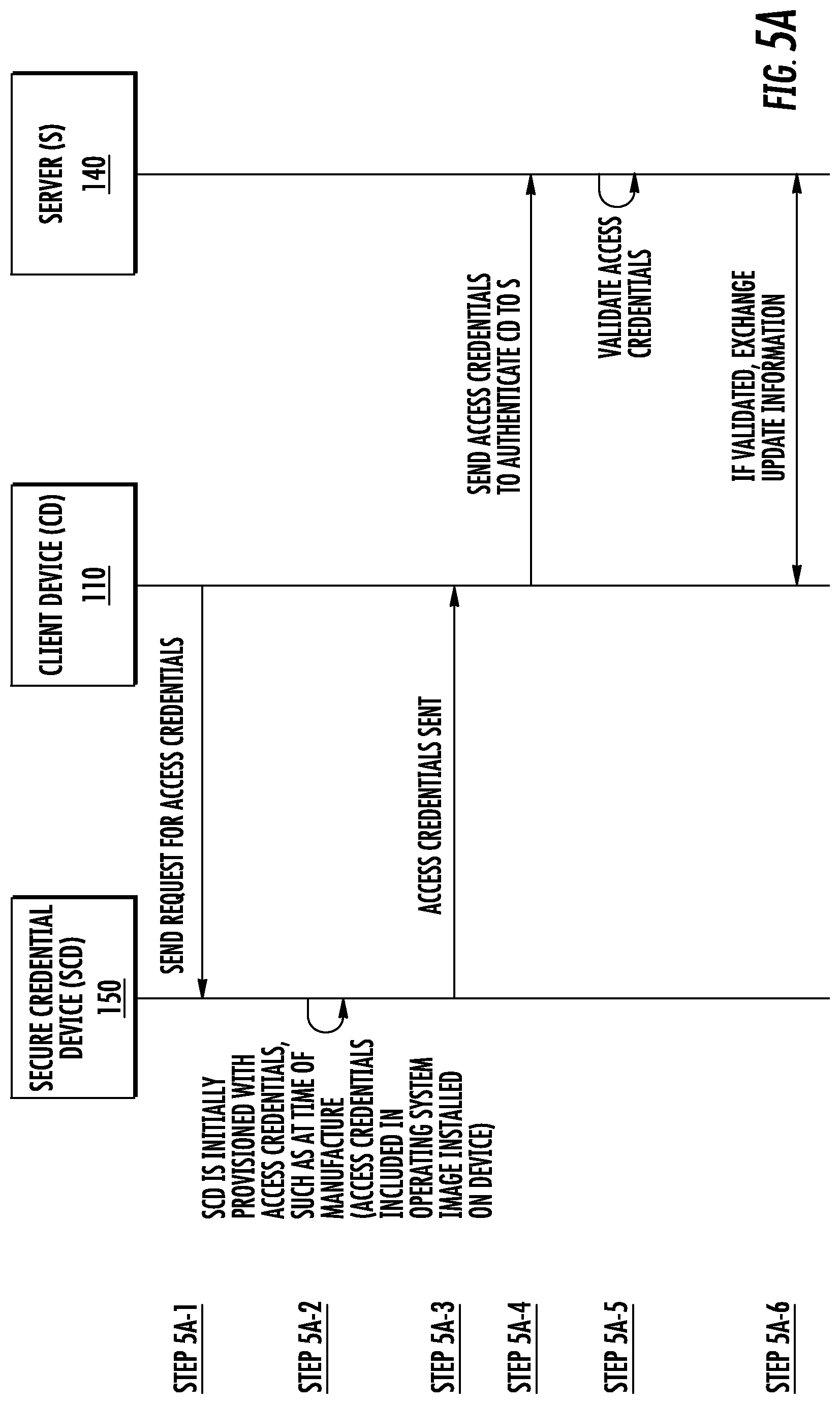
FIG. 5A and FIG. 5B are schematics outlining the procurement of access credentials by an unattended client device according to embodiments of the present invention.
DETAILED DESCRIPTION
The present invention embraces the concept of unattended devices procuring access credentials for network access and/or data encryption so that updates may be received from servers and/or information exchanged with servers in a manner that does not compromise security or increase labor overhead.
In the present disclosure, "unattended" refers to the fact that the client device is not operated by a user who has authenticated to the device (by password, PIN, smartcard, biometric, etc.) at the time that the client device procures the access credentials necessary to allow the device to exchange information with and/or receive updates from servers on a network. Unattended client devices may procure access credentials by timed or triggered means that are well understood in the art, i.e. client devices may procure the access credentials according to a regular time schedule or in response to some triggering event, such as a notification of new data to exchange or the availability of a new update.
Also, in the present disclosure, "pairing credentials" refer to those credentials which authenticate the client device to a token server, and "access credentials" refer to those credentials which authenticate the client device to a server and/or decrypt an encrypted file system on the client device. The "access credential" includes, but is not limited to, a one-time password, a symmetric key, a public key along with its private key, for instance using the public key cryptography standards (PKCS) certificate formats, or the like.
Further, in the present disclosure, "authentication credentials" refer to those credentials which authenticate the client device and the secure credential device.
In the specification and/or figures, typical embodiments of the invention have been disclosed. The present invention is not limited to such exemplary embodiments. The use of the term "and/or" includes any and all combinations of one or more of the associated listed items. The figures are schematic representations and so are not necessarily drawn to scale. Unless otherwise noted, specific terms have been used in a generic and descriptive sense and not for purposes of limitation.
FIG. 1A illustrates an exemplary system 100 for one embodiment of the present invention. In general, the system 100 includes a client device (CD) 110, a secure credential device (SCD) 150, a token server (TS) 130, and a server (S) 140. The client device 110, secure credential device 150, token server 130, and server 140 may be implemented in any form of digital computer or mobile device. Digital computers may include, but are not limited to, laptops, desktops, workstations, fixed vehicle computers, vehicle mount computers, hazardous environment computers, rugged mobile computers, servers, blade servers, mainframes, other appropriate computers. Mobile devices may include, but are not limited to, cellular telephones, smart phones, personal digital assistants, tablets, pagers, two-way radios, netbooks, barcode scanners, radio frequency identification (RFID) readers, intelligent sensors, tracking devices, and other similar computing devices.
In some embodiments of the present invention, the client device 110, secure credential device 150, token server 130, and server 140 are connected via a network 170. The network 170 may be any type of wide area network (WAN), such as the Internet, Local Area Network (LAN), or the like, or any combination thereof, and may include wired components, such as Ethernet, wireless components, such as LTE, Wi-Fi, Bluetooth, or near field communication (NFC), or both wired and wireless components, collectively represented by the data links 172, 174, 176, and 178.
Note that while token server 130 and server 140 are illustrated in FIG. 1A, FIG. 1B, FIG. 4A, and FIG. 4B as individual single servers, each may alternatively be distributed across multiple servers having the respective functionality of the token server 130 and server 140. And still in other embodiments, the token server 130 and server 140 may also be combined into one single server or distributed across multiple servers having the overall combined functionality of token server 130 and server 140.
In general, the server 140 includes at least one processor 142 and associated memory 144 and a communication interface 148, such as wired Ethernet or wireless such as Wi-Fi, Bluetooth or NFC. The server 140 may also include additional components such as a storage component 146. The components of server 140 may be interconnected using one or more buses 141 and may be mounted on a motherboard (not shown) or some other appropriate configuration.
Similarly, in general, the token server 130 includes at least one processor 132 and associated memory 134 and a communication interface 138, such as wired Ethernet or wireless such as Wi-Fi, Bluetooth or NFC. The token server 130 may also include additional components such as a storage component 136. The components of token server 130 may be interconnected using one or more buses 131 and may be mounted on a motherboard (not shown) or some other appropriate configuration.
Further, in general, the secure credential device 150 includes at least one processor 152 and associated memory 154 and a communication interface 158, such as wired Ethernet or wireless such as Wi-Fi, Bluetooth or NFC. The secure credential device 150 may also include additional components such as a secure storage element 160 and slots/ports 156. The components of the secure credential device 150 may be interconnected using one or more buses 151 and may be mounted on a motherboard (not shown) or some other appropriate configuration. The secured credential device 150 has a wired communication channel 164 connecting it to the client device 110. The wired communication channel 164 may be USB, I.sup.2C, or other computer bus. In one embodiment, the wired communication channel 164 between the secure credential device 150 and the client device 110 can be protected by authentication; in this embodiment, the client device 110 stores the authentication credentials in the secure storage element 160 during an initial provisioning process that occurs while the client device 110 is still authenticated with a user. The secure credential device is also fixed in location 162, meaning that it is non-moveable.
The secure credential device 150 is built for tamper detection, tamper resistance, or both. In some embodiments, just specific components of the secure credential device 150 may be built for tamper detection, tamper resistance, or both, such as the secure storage element 160. Tamper detection methods include, but are not limited to, detection of ultraviolet fluorescent chemicals, detection of varying temperature, detection of varying clocking information, detection of varying voltage, and detection of varying electrical signals. Tamper resistance methods include, but are not limited to, the use of a potted material which would destroy one or more components of the secure credential device 150, such as the secure storage element 160, upon removal. Other tamper detection and tamper resistant methods are understood in the art and may be employed herein. In some embodiments, the secure credential device would report the detected tampering and might cause temporary or permanent disablement of the secure credential device. In yet other embodiments, where the secure storage element 160 of the secure credential device 150 implements tamper control that is acceptable and the communication interface 158 is wireless, the secure credential device 150 may further be designed to meet FIPS-140-2 by layering a protocol on top of the base wireless that uses validated encryption algorithms such as Advanced Encryption Standard (AES). In these embodiments, additional wireless encryption pairing credentials would be required between the secure credential device 150 and token server 130 to derive a link key for the validated encryption algorithm.
In one embodiment, the secure credential device 150 would be a dock for the client device 110. The dock would have the ability to cache access credentials and would include one or more mechanisms for providing user level authentication, including but not limited to: a common access card (CAC) reader, a touchscreen, a keypad, and a display for password entry. The dock further provides the recharging of the battery and ensures the essential constant power supply to the client device 110 during critical software and firmware updates.
In general, the client device 110 includes a processor 112 and associated memory 116 as well as a communication interface 122, such as wired Ethernet or wireless such as Wi-Fi, Bluetooth, or NFC. The client device 110 may include additional components such as a storage component 118 such as a hard drive or solid state drive, a location determination component 134 such as a Global Positioning System (GPS) chip, audio input component 124 such as a microphone, audio output component 128 such as a speaker, visual input component 126 such as a camera or barcode reader, visual output component 130 such as a display, and a user input component 120 such as a touchscreen, navigation shuttle, soft keys, or the like, and slots/ports 132 which may be used for smart card readers or for wired connections 164 with the secure credential device 150 over USB, I2C, or computer bus. The components of client device 110 may be interconnected using one or more buses 114 and may be mounted on a motherboard (not shown) or some other appropriate configuration.
FIG. 1B illustrates another embodiment of the present invention. The embodiment in FIG. 1B is similar to FIG. 1A with the exception that in FIG. 1B, the secure credential device 150 is internal to the client device 110. While FIG. 1B illustrates separate components for the client device 110 and secure credential device 150, in an alternative embodiment, the comparable components from the client device 110 and secure credential device 150 could be the same, i.e. processor 112 and 152, memory 116 and 154, communication interface 122 and 158, and communication link 172 and 178, and there may not be a need for slots/ports 132 and 156, since bus 114 and 151 may be the same. In some embodiments, the storage 118 and secure storage element 160 could also be the same, provided that the combination of the secure credential device 150 and client device 110 still allow for tamper detection, tamper resistance, or both.
FIG. 2A illustrates one embodiment of the present invention where the token server pairing credentials are initially provisioned on the secure credential device 150 using out of band means. In Step 2A-1, the pairing credentials are provisioned on the secure credential device 150 by a user who manually enters the credentials, copies them from a thumb drive or flash drive, or transfers them using NFC. In Step 2A-2, the secure credential device 150 then securely stores the pairing credentials in the secure storage element 160 for use in future sessions.
FIG. 2B illustrates an alternative embodiment of the present invention where the token server pairing credentials are initially provisioned on the secure credential device by pairing with the token server 130. In step 2B-1, the secure credential device 150 sends a pairing request with initial credentials to the token server 130. In step 2B-2, the token server 130 accepts the pairing request, and in step 2B-3, the token server and secure credential device exchange pairing credentials (i.e. the pairing key). In step 2B-4, the secure credential device then stores the pairing credentials for use in future sessions.
FIG. 3A illustrates the communication flow between the elements of system 100 of FIGS. 1A and 1B where the client device 110 procures access credentials from the token server 130 through the secure credential device 150 for accessing server 140. In step 3A-1, the client device 110 sends a request for the access credentials to the secure credential device 150. In step 3A-2, the secure credential device 150 sends a request for the access credentials to the token server 130. The secure credential device 150 and token sever 130 exchange pairing credentials to authenticate (Step 3A-3), and if authenticated (Step 3A-4), the token server 130 sends the access credentials to the secure credential device 150. In step 3A-5, the secure credential device 150 then stores the access credentials for use in a future session. In other embodiments, the secure credential device 150 does not store the access credentials but obtains them from the token server 130 each time the client device 110 needs to access the server 140, such as might be required in highly secure environments when the access credentials may be changing with greater frequency. In step 3A-6, the secure credential device 150 then sends the access credentials to the client device 110, which then sends them to the server 140 (Step 3A-7). If the server validates the access credentials (Step 3A-8), then the client device 110 and server 140 exchange information (Step 3A-9). The information exchanged includes, but is not limited to, firmware updates, operating system updates, application and/or program code updates, configuration setting changes, and customer data exchange.
FIG. 3B illustrates another embodiment of the present invention. The embodiment in FIG. 3B is similar to FIG. 3A with the exception that in FIG. 3B, there is the added step 3B-9 where the access credentials are used to unlock the local encrypted file system on the client device 110 so that information may be exchanged with server 140.
FIG. 4A illustrates yet another embodiment of the present invention. In this embodiment, the secure credential device 150 is external to the client device 110 but does not contain a communication interface for communicating with the token server 130 as in FIG. 1A. Because the secure credential device cannot communicate with the token server 130, it must be initially provisioned with the access credentials, such as at the time of manufacture where the access credentials would be included in the operating system image installed on the secure credential device.
FIG. 4B illustrates another embodiment of the present invention. In this embodiment, the secure credential device 150 is internal to the client device 110. While FIG. 4B illustrates separate components for the client device 110 and secure credential device 150, in an alternative embodiment, the comparable components could be the same, i.e. processor 112 and 152, and memory 116 and 154, and there may not be a need for slots/ports 132 and 156, since bus 114 and 151 may be the same. In some embodiments, the storage 118 and secure storage element 160 could also be the same, provided that the combination of the secure credential device 150 and client device 110 still allow for tamper detection, tamper resistance, or both.
FIG. 5A illustrates the communication flow between the elements of system 100 of FIGS. 4A and 4B where the client device 110 procures access credentials from the secure credential device 150 for accessing server 140. In step 5A-1, the client device 110 sends a request for access credentials to the secure credential device 150. Because the secure credential device 150 has already been provisioned with the access credentials at time of manufacture (Step 5A-2), then the secure credential device 150 can just send the access credentials to the client device 110 (Step 5A-3) which then sends them to the server 140 (Step 5A-4). If the access credentials are validated (Step 5A-5), then the client device 110 and server 140 exchange information (Step 5A-6). As before, the information exchanged includes, but is not limited to, firmware updates, operating system updates, application and/or program code updates, configuration setting changes, and customer data exchange. In some embodiments, the secure credential device 150 could be equivalent to a smartcard that could be used to perform the symmetric or private key encryption.
FIG. 5B illustrates another embodiment of the present invention. The embodiment in FIG. 5B is similar to FIG. 5A with the exception that in FIG. 5B, there is the added step 5B-6 where the access credentials are used to unlock the local encrypted file system on the client device 110 so that information may be exchanged with server 140.
Several implementations have been described herein. However, it will be understood that various modifications may be made without departing from the spirit and scope of the invention.
Additionally, the communication flows in the schematics of the figures do not require the particular order shown or sequential order to achieve the specified results. Further, other steps may be provided or eliminated from the schematics and other components may be added to or removed from the described systems. These other implementations are within the scope of the claims.
The following represent exemplary embodiments of the present disclosure.
A1. A system, comprising:
an unattended first device comprising: a first communication interface; a first control system communicatively coupled to the first communication interface and comprising at least one first hardware processor and a first memory storing program codes operable to: send a request to the second device for access credentials; receive the access credentials; send the access credentials to the fourth device; and if the access credentials is validated, exchange information with the fourth device.
a second device comprising: a second communication interface; a second secured storage element; a second control system communicatively coupled to the second communication interface and comprising at least one second hardware processor and a second memory storing program codes operable to: receive a request for the access credentials from the first device; send a request for the access credentials to the third device; exchange pairing credentials with the third device to authenticate with the third device; if authenticated with the third device, receive the access credentials; and send the access credentials to the first device;
a third device comprising: a third communication interface; a third control system communicatively coupled to the third communication interface and comprising at least one third hardware processor and a third memory storing program codes operable to: receive a request for the access credentials from the second device; exchange pairing credentials with the second device to authenticate with the second device; if authenticated with the second device, send the access credentials to the second device; and
a fourth device comprising: a fourth communication interface; a fourth control system communicatively coupled to the fourth communication interface and comprising at least one fourth hardware processor and a fourth memory storing program codes operable to: receive access credentials from the first device; validate the access credentials; and if validated, exchange information with the first device. A2. The system of embodiment A1, wherein the second device is internal to the first device. A3. The system of embodiment A1, further comprising the first device using the access credentials to decrypt an encrypted file system. A4. The system of embodiment A1, wherein the information exchanged between the fourth device and the first device comprises one of the group consisting of: information to update software on the first device, information to update firmware on the first device, information to update applications on the first device, information to update program codes on the first device, information to make configuration setting changes on the first device, information to update the operating system on the first device, and information pertaining to customer data. A5. The system of embodiment A1, wherein the pairing credentials stored in the second device are stored in a tamper resistant manner. A6. The system of embodiment A5, wherein the tamper resistant manner comprises use of potted material which would destroy one or more components of the second device upon removal. A7. The system of embodiment A1, wherein the pairing credentials stored in the second device are stored in a manner to provide for tamper detection. A8. The system of embodiment A7, wherein the manner to provide for tamper detection comprises one of the group consisting of: detection of ultraviolet fluorescent chemicals, detection of varying temperature, detection of varying clocking information, detection of varying voltage, and detection of varying electrical signals. A9. The system of embodiment A7, wherein the second device, upon tamper detection, is further operable to: report the detected tampering; and disable one or more components of the second device. A10. The system of embodiment A1, wherein the pairing credentials are stored according to National Institute of Standards and Technology (NIST) standards. A11. The system of embodiment A1, wherein the pairing credentials exchanged between the second and third device are exchanged by out-of-band means. A12. The system of embodiment A11, wherein the out-of-band means comprises one of the group consisting of: direct user input at the second and third devices, use of a thumb drive at the second and third devices, use of a universal serial bus (USB) cable between the second and third device, or use of wired Ethernet cable between the second and third device. A13. The system of embodiment A1, wherein the pairing credentials exchanged between the second and third device are exchanged by use of a wireless communication channel. A14. The system of embodiment A13, wherein the wireless communication channel comprises one of the group consisting of: Bluetooth and a near field communication (NFC). A15. The system of embodiment A14, wherein the wireless communication channel is secured with an encryption algorithm. A16. The system of embodiment A1, wherein the second device is a dock for the first device with at least one mechanism for providing user level authentication, wherein the mechanism for providing user level authentication is selected from the group consisting of: a common access card (CAC) reader, a touchscreen, a keypad, and a display for password entry. A17. The system of embodiment A1, wherein the access credentials comprise one of a group consisting of: a one-time password, a symmetric key, a public key along with its private key, and a public key cryptography standard (PKCS) certificate. A18. The system of embodiment A1, wherein the second device is further operable to: send a pairing request with initial credentials to the third device; receive an acceptance of the pairing request form the third device; and exchange pairing credentials with the third device. A19. The system of embodiment A1, wherein the third device is further operable to: receive a pairing request with initial credentials from the second device; send an acceptance of the pairing request to the second device; and exchange pairing credentials with the second device. A20. The system of embodiment A1, wherein the second device is further operable to: store the access credentials. A21. The system of embodiment A20, wherein the access credentials are stored in a tamper resistant manner. A22. The system of embodiment A21, wherein the tamper resistant manner comprises use of potted material which would destroy one or more components of the second device upon removal. A23. The system of embodiment A20, wherein the access credentials are stored in a manner to provide for tamper detection. A24. The system of embodiment A23, wherein the manner to provide for tamper detection comprises: detection of ultraviolet fluorescent chemicals, detection of varying temperature, detection of varying clocking information, detection of varying voltage, and detection of varying electrical signals. A25. The system of embodiment A23, wherein the second device, upon tamper detection, is further operable to: report the detected tampering; and disable one or more components of the second device. B26. A system, comprising: an unattended first device comprising: a first communication interface; a first control system communicatively coupled to the first communication interface and comprising at least one first hardware processor and a first memory storing program codes operable to: send a request to the second device for access credentials; receive the access credentials; send the access credentials to the third device; and if the access credentials are validated, exchange information with the third device. a second device comprising: a second communication interface; a second secured storage element; a second control system communicatively coupled to the second communication interface and comprising at least one second hardware processor and a second memory storing program codes operable to: receive a request for the access credentials from the first device; and send the access credentials to the first device; and a third device comprising: a third communication interface; a third control system communicatively coupled to the third communication interface and comprising at least one third hardware processor and a third memory storing program codes operable to: receive the access credentials from the first device; validate the access credentials; and if validated, exchange information with the first device. B27. The system of embodiment B26, wherein the second device is internal to the first device. B28. The system of embodiment B26, further comprising the first device using the access credentials to decrypt an encrypted file system. B29. The system of embodiment B26, wherein the information exchanged between the third device and the first device comprises one of the group consisting of: information to update software on the first device, information to update firmware on the first device, information to update applications on the first device, information to update program codes on the first device, information to make configuration setting changes on the first device, information to update the operating system on the first device, and information pertaining to customer data. B30. The system of embodiment B26, wherein the second device stores the access credentials in a tamper resistant manner. B31. The system of embodiment B30, wherein the tamper resistant manner comprises use of potted material which would destroy one or more components of the second device upon removal. B32. The system of embodiment B30, wherein the second device stores the access credentials in a manner to provide for tamper detection. B33. The system of embodiment B32, wherein the manner to provide for tamper detection comprises: detection of ultraviolet fluorescent chemicals, detection of varying temperature, detection of varying clocking information, detection of varying voltage, and detection of varying electrical signals. B34. The system of embodiment B32, wherein the second device, upon tamper detection, is further operable to: report the detected tampering; and disable one or more components of the second device. B35. The system of embodiment B26, wherein the second device stores the access credentials according to NIST standards. B36. The system of embodiment B26, wherein the access credentials comprise one of a group consisting of: a one-time password, a symmetric key, a public key along with its private key, and a PKCS certificate format. B37. The system of embodiment B26, wherein the second device is initially provisioned with the access credentials. B38. The system of embodiment 37, wherein the initial provisioning comprises the inclusion of the access credentials in the operating system image installed on the second device.
To supplement the present disclosure, this application incorporates entirely by reference the following commonly assigned patents, patent application publications, and patent applications: U.S. Pat. Nos. 6,832,725; 7,128,266; U.S. Pat. Nos. 7,159,783; 7,413,127; U.S. Pat. Nos. 7,726,575; 8,294,969; U.S. Pat. Nos. 8,317,105; 8,322,622; U.S. Pat. Nos. 8,366,005; 8,371,507; U.S. Pat. Nos. 8,376,233; 8,381,979; U.S. Pat. Nos. 8,390,909; 8,408,464; U.S. Pat. Nos. 8,408,468; 8,408,469; U.S. Pat. Nos. 8,424,768; 8,448,863; U.S. Pat. Nos. 8,457,013; 8,459,557; U.S. Pat. Nos. 8,469,272; 8,474,712; U.S. Pat. Nos. 8,479,992; 8,490,877; U.S. Pat. Nos. 8,517,271; 8,523,076; U.S. Pat. Nos. 8,528,818; 8,544,737; U.S. Pat. Nos. 8,548,242; 8,548,420; U.S. Pat. Nos. 8,550,335; 8,550,354; U.S. Pat. Nos. 8,550,357; 8,556,174; U.S. Pat. Nos. 8,556,176; 8,556,177; U.S. Pat. Nos. 8,559,767; 8,599,957; U.S. Pat. Nos. 8,561,895; 8,561,903; U.S. Pat. Nos. 8,561,905; 8,565,107; U.S. Pat. Nos. 8,571,307; 8,579,200; U.S. Pat. Nos. 8,583,924; 8,584,945; U.S. Pat. Nos. 8,587,595; 8,587,697; U.S. Pat. Nos. 8,588,869; 8,590,789; U.S. Pat. Nos. 8,596,539; 8,596,542; U.S. Pat. Nos. 8,596,543; 8,599,271; U.S. Pat. Nos. 8,599,957; 8,600,158; U.S. Pat. Nos. 8,600,167; 8,602,309; U.S. Pat. Nos. 8,608,053; 8,608,071; U.S. Pat. Nos. 8,611,309; 8,615,487; U.S. Pat. Nos. 8,616,454; 8,621,123; U.S. Pat. Nos. 8,622,303; 8,628,013; U.S. Pat. Nos. 8,628,015; 8,628,016; U.S. Pat. Nos. 8,629,926; 8,630,491; U.S. Pat. Nos. 8,635,309; 8,636,200; U.S. Pat. Nos. 8,636,212; 8,636,215; U.S. Pat. Nos. 8,636,224; 8,638,806; U.S. Pat. Nos. 8,640,958; 8,640,960; U.S. Pat. Nos. 8,643,717; 8,646,692; U.S. Pat. Nos. 8,646,694; 8,657,200; U.S. Pat. Nos. 8,659,397; 8,668,149; U.S. Pat. Nos. 8,678,285; 8,678,286; U.S. Pat. Nos. 8,682,077; 8,687,282; U.S. Pat. Nos. 8,692,927; 8,695,880; U.S. Pat. Nos. 8,698,949; 8,717,494; U.S. Pat. Nos. 8,717,494; 8,720,783; U.S. Pat. Nos. 8,723,804; 8,723,904; U.S. Pat. Nos. 8,727,223; U.S. Pat. No. D702,237; U.S. Pat. Nos. 8,740,082; 8,740,085; U.S. Pat. Nos. 8,746,563; 8,750,445; U.S. Pat. Nos. 8,752,766; 8,756,059; U.S. Pat. Nos. 8,757,495; 8,760,563; U.S. Pat. Nos. 8,763,909; 8,777,108; U.S. Pat. Nos. 8,777,109; 8,779,898; U.S. Pat. Nos. 8,781,520; 8,783,573; U.S. Pat. Nos. 8,789,757; 8,789,758; U.S. Pat. Nos. 8,789,759; 8,794,520; U.S. Pat. Nos. 8,794,522; 8,794,526; U.S. Pat. Nos. 8,798,367; 8,807,431; U.S. Pat. Nos. 8,807,432; 8,820,630; International Publication No. 2013/163789; International Publication No. 2013/173985; International Publication No. 2014/019130; International Publication No. 2014/110495; U.S. Patent Application Publication No. 2008/0185432; U.S. Patent Application Publication No. 2009/0134221; U.S. Patent Application Publication No. 2010/0177080; U.S. Patent Application Publication No. 2010/0177076; U.S. Patent Application Publication No. 2010/0177707; U.S. Patent Application Publication No. 2010/0177749; U.S. Patent Application Publication No. 2011/0202554; U.S. Patent Application Publication No. 2012/0111946; U.S. Patent Application Publication No. 2012/0138685; U.S. Patent Application Publication No. 2012/0168511; U.S. Patent Application Publication No. 2012/0168512; U.S. Patent Application Publication No. 2012/0193423; U.S. Patent Application Publication No. 2012/0203647; U.S. Patent Application Publication No. 2012/0223141; U.S. Patent Application Publication No. 2012/0228382; U.S. Patent Application Publication No. 2012/0248188; U.S. Patent Application Publication No. 2013/0043312; U.S. Patent Application Publication No. 2013/0056285; U.S. Patent Application Publication No. 2013/0070322; U.S. Patent Application Publication No. 2013/0075168; U.S. Patent Application Publication No. 2013/0082104; U.S. Patent Application Publication No. 2013/0175341; U.S. Patent Application Publication No. 2013/0175343; U.S. Patent Application Publication No. 2013/0200158; U.S. Patent Application Publication No. 2013/0256418; U.S. Patent Application Publication No. 2013/0257744; U.S. Patent Application Publication No. 2013/0257759; U.S. Patent Application Publication No. 2013/0270346; U.S. Patent Application Publication No. 2013/0278425; U.S. Patent Application Publication No. 2013/0287258; U.S. Patent Application Publication No. 2013/0292475; U.S. Patent Application Publication No. 2013/0292477; U.S. Patent Application Publication No. 2013/0293539; U.S. Patent Application Publication No. 2013/0293540; U.S. Patent Application Publication No. 2013/0306728; U.S. Patent Application Publication No. 2013/0306730; U.S. Patent Application Publication No. 2013/0306731; U.S. Patent Application Publication No. 2013/0307964; U.S. Patent Application Publication No. 2013/0308625; U.S. Patent Application Publication No. 2013/0313324; U.S. Patent Application Publication No. 2013/0313325; U.S. Patent Application Publication No. 2013/0341399; U.S. Patent Application Publication No. 2013/0342717; U.S. Patent Application Publication No. 2014/0001267; U.S. Patent Application Publication No. 2014/0002828; U.S. Patent Application Publication No. 2014/0008430; U.S. Patent Application Publication No. 2014/0008439; U.S. Patent Application Publication No. 2014/0025584; U.S. Patent Application Publication No. 2014/0027518; U.S. Patent Application Publication No. 2014/0034734; U.S. Patent Application Publication No. 2014/0036848; U.S. Patent Application Publication No. 2014/0039693; U.S. Patent Application Publication No. 2014/0042814; U.S. Patent Application Publication No. 2014/0049120; U.S. Patent Application Publication No. 2014/0049635; U.S. Patent Application Publication No. 2014/0061305; U.S. Patent Application Publication No. 2014/0061306; U.S. Patent Application Publication No. 2014/0063289; U.S. Patent Application Publication No. 2014/0066136; U.S. Patent Application Publication No. 2014/0067692; U.S. Patent Application Publication No. 2014/0070005; U.S. Patent Application Publication No. 2014/0071840; U.S. Patent Application Publication No. 2014/0074746; U.S. Patent Application Publication No. 2014/0075846; U.S. Patent Application Publication No. 2014/0076974; U.S. Patent Application Publication No. 2014/0078341; U.S. Patent Application Publication No. 2014/0078342; U.S. Patent Application Publication No. 2014/0078345; U.S. Patent Application Publication No. 2014/0084068; U.S. Patent Application Publication No. 2014/0097249; U.S. Patent Application Publication No. 2014/0098792; U.S. Patent Application Publication No. 2014/0100774; U.S. Patent Application Publication No. 2014/0100813; U.S. Patent Application Publication No. 2014/0103115; U.S. Patent Application Publication No. 2014/0104413; U.S. Patent Application Publication No. 2014/0104414; U.S. Patent Application Publication No. 2014/0104416; U.S. Patent Application Publication No. 2014/0104451; U.S. Patent Application Publication No. 2014/0106594; U.S. Patent Application Publication No. 2014/0106725; U.S. Patent Application Publication No. 2014/0108010; U.S. Patent Application Publication No. 2014/0108402; U.S. Patent Application Publication No. 2014/0108682; U.S. Patent Application Publication No. 2014/0110485; U.S. Patent Application Publication No. 2014/0114530; U.S. Patent Application Publication No. 2014/0124577; U.S. Patent Application Publication No. 2014/0124579; U.S. Patent Application Publication No. 2014/0125842; U.S. Patent Application Publication No. 2014/0125853; U.S. Patent Application Publication No. 2014/0125999; U.S. Patent Application Publication No. 2014/0129378; U.S. Patent Application Publication No. 2014/0131438; U.S. Patent Application Publication No. 2014/0131441; U.S. Patent Application Publication No. 2014/0131443; U.S. Patent Application Publication No. 2014/0131444; U.S. Patent Application Publication No. 2014/0131445; U.S. Patent Application Publication No. 2014/0131448; U.S. Patent Application Publication No. 2014/0133379; U.S. Patent Application Publication No. 2014/0136208; U.S. Patent Application Publication No. 2014/0140585; U.S. Patent Application Publication No. 2014/0151453; U.S. Patent Application Publication No. 2014/0152882; U.S. Patent Application Publication No. 2014/0158770; U.S. Patent Application Publication No. 2014/0159869; U.S. Patent Application Publication No. 2014/0160329; U.S. Patent Application Publication No. 2014/0166755; U.S. Patent Application Publication No. 2014/0166757; U.S. Patent Application Publication No. 2014/0166759; U.S. Patent Application Publication No. 2014/0166760; U.S. Patent Application Publication No. 2014/0166761; U.S. Patent Application Publication No. 2014/0168787; U.S. Patent Application Publication No. 2014/0175165; U.S. Patent Application Publication No. 2014/0175169; U.S. Patent Application Publication No. 2014/0175172; U.S. Patent Application Publication No. 2014/0175174; U.S. Patent Application Publication No. 2014/0191644; U.S. Patent Application Publication No. 2014/0191913; U.S. Patent Application Publication No. 2014/0197238; U.S. Patent Application Publication No. 2014/0197239; U.S. Patent Application Publication No. 2014/0197304; U.S. Patent Application Publication No. 2014/0203087; U.S. Patent Application Publication No. 2014/0204268; U.S. Patent Application Publication No. 2014/0214631; U.S. Patent Application Publication No. 2014/0217166; U.S. Patent Application Publication No. 2014/0217180; U.S. patent application Ser. No. 13/367,978 for a Laser Scanning Module Employing an Elastomeric U-Hinge Based Laser Scanning Assembly, filed Feb. 7, 2012 (Feng et al.); U.S. patent application Ser. No. 29/436,337 for an Electronic Device, filed Nov. 5, 2012 (Fitch et al.); U.S. patent application Ser. No. 13/771,508 for an Optical Redirection Adapter, filed Feb. 20, 2013 (Anderson); U.S. patent application Ser. No. 13/852,097 for a System and Method for Capturing and Preserving Vehicle Event Data, filed Mar. 28, 2013 (Barker et al.); U.S. patent application Ser. No. 13/902,110 for a System and Method for Display of Information Using a Vehicle-Mount Computer, filed May 24, 2013 (Hollifield); U.S. patent application Ser. No. 13/902,144, for a System and Method for Display of Information Using a Vehicle-Mount Computer, filed May 24, 2013 (Chamberlin); U.S. patent application Ser. No. 13/902,242 for a System For Providing A Continuous Communication Link With A Symbol Reading Device, filed May 24, 2013 (Smith et al.); U.S. patent application Ser. No. 13/912,262 for a Method of Error Correction for 3D Imaging Device, filed Jun. 7, 2013 (Jovanovski et al.); U.S. patent application Ser. No. 13/912,702 for a System and Method for Reading Code Symbols at Long Range Using Source Power Control, filed Jun. 7, 2013 (Xian et al.); U.S. patent application Ser. No. 29/458,405 for an Electronic Device, filed Jun. 19, 2013 (Fitch et al.); U.S. patent application Ser. No. 13/922,339 for a System and Method for Reading Code Symbols Using a Variable Field of View, filed Jun. 20, 2013 (Xian et al.); U.S. patent application Ser. No. 13/927,398 for a Code Symbol Reading System Having Adaptive Autofocus, filed Jun. 26, 2013 (Todeschini); U.S. patent application Ser. No. 13/930,913 for a Mobile Device Having an Improved User Interface for Reading Code Symbols, filed Jun. 28, 2013 (Gelay et al.); U.S. patent application Ser. No. 29/459,620 for an Electronic Device Enclosure, filed Jul. 2, 2013 (London et al.); U.S. patent application Ser. No. 29/459,681 for an Electronic Device Enclosure, filed Jul. 2, 2013 (Chaney et al.); U.S. patent application Ser. No. 13/933,415 for an Electronic Device Case, filed Jul. 2, 2013 (London et al.); U.S. patent application Ser. No. 29/459,785 for a Scanner and Charging Base, filed Jul. 3, 2013 (Fitch et al.); U.S. patent application Ser. No. 29/459,823 for a Scanner, filed Jul. 3, 2013 (Zhou et al.); U.S. patent application Ser. No. 13/947,296 for a System and Method for Selectively Reading Code Symbols, filed Jul. 22, 2013 (Rueblinger et al.); U.S. patent application Ser. No. 13/950,544 for a Code Symbol Reading System Having Adjustable Object Detection, filed Jul. 25, 2013 (Jiang); U.S. patent application Ser. No. 13/961,408 for a Method for Manufacturing Laser Scanners, filed Aug. 7, 2013 (Saber et al.); U.S. patent application Ser. No. 14/018,729 for a Method for Operating a Laser Scanner, filed Sep. 5, 2013 (Feng et al.); U.S. patent application Ser. No. 14/019,616 for a Device Having Light Source to Reduce Surface Pathogens, filed Sep. 6, 2013 (Todeschini); U.S. patent application Ser. No. 14/023,762 for a Handheld Indicia Reader Having Locking Endcap, filed Sep. 11, 2013 (Gannon); U.S. patent application Ser. No. 14/035,474 for Augmented-Reality Signature Capture, filed Sep. 24, 2013 (Todeschini); U.S. patent application Ser. No. 29/468,118 for an Electronic Device Case, filed Sep. 26, 2013 (Oberpriller et al.); U.S. patent application Ser. No. 14/055,234 for Dimensioning System, filed Oct. 16, 2013 (Fletcher); U.S. patent application Ser. No. 14/053,314 for Indicia Reader, filed Oct. 14, 2013 (Huck); U.S. patent application Ser. No. 14/065,768 for Hybrid System and Method for Reading Indicia, filed Oct. 29, 2013 (Meier et al.); U.S. patent application Ser. No. 14/074,746 for Self-Checkout Shopping System, filed Nov. 8, 2013 (Hejl et al.); U.S. patent application Ser. No. 14/074,787 for Method and System for Configuring Mobile Devices via NFC Technology, filed Nov. 8, 2013 (Smith et al.); U.S. patent application Ser. No. 14/087,190 for Optimal Range Indicators for Bar Code Validation, filed Nov. 22, 2013 (Hejl); U.S. patent application Ser. No. 14/094,087 for Method and System for Communicating Information in an Digital Signal, filed Dec. 2, 2013 (Peake et al.); U.S. patent application Ser. No. 14/101,965 for High Dynamic-Range Indicia Reading System, filed Dec. 10, 2013 (Xian); U.S. patent application Ser. No. 14/150,393 for Indicia-reader Having Unitary Construction Scanner, filed Jan. 8, 2014 (Colavito et al.); U.S. patent application Ser. No. 14/154,207 for Laser Barcode Scanner, filed Jan. 14, 2014 (Hou et al.); U.S. patent application Ser. No. 14/165,980 for System and Method for Measuring Irregular Objects with a Single Camera filed Jan. 28, 2014 (Li et al.); U.S. patent application Ser. No. 14/166,103 for Indicia Reading Terminal Including Optical Filter filed Jan. 28, 2014 (Lu et al.); U.S. patent application Ser. No. 14/200,405 for Indicia Reader for Size-Limited Applications filed Mar. 7, 2014 (Feng et al.); U.S. patent application Ser. No. 14/231,898 for Hand-Mounted Indicia-Reading Device with Finger Motion Triggering filed Apr. 1, 2014 (Van Horn et al.); U.S. patent application Ser. No. 14/250,923 for Reading Apparatus Having Partial Frame Operating Mode filed Apr. 11, 2014, (Deng et al.); U.S. patent application Ser. No. 14/257,174 for Imaging Terminal Having Data Compression filed Apr. 21, 2014, (Barber et al.); U.S. patent application Ser. No. 14/257,364 for Docking System and Method Using Near Field Communication filed Apr. 21, 2014 (Showering); U.S. patent application Ser. No. 14/264,173 for Autofocus Lens System for Indicia Readers filed Apr. 29, 2014 (Ackley et al.); U.S. patent application Ser. No. 14/274,858 for Mobile Printer with Optional Battery Accessory filed May 12, 2014 (Marty et al.); U.S. patent application Ser. No. 14/277,337 for MULTIPURPOSE OPTICAL READER, filed May 14, 2014 (Jovanovski et al.); U.S. patent application Ser. No. 14/283,282 for TERMINAL HAVING ILLUMINATION AND FOCUS CONTROL filed May 21, 2014 (Liu et al.); U.S. patent application Ser. No. 14/300,276 for METHOD AND SYSTEM FOR CONSIDERING INFORMATION ABOUT AN EXPECTED RESPONSE WHEN PERFORMING SPEECH RECOGNITION, filed Jun. 10, 2014 (Braho et al.); U.S. patent application Ser. No. 14/305,153 for INDICIA READING SYSTEM EMPLOYING DIGITAL GAIN CONTROL filed Jun. 16, 2014 (Xian et al.); U.S. patent application Ser. No. 14/310,226 for AUTOFOCUSING OPTICAL IMAGING DEVICE filed Jun. 20, 2014 (Koziol et al.); U.S. patent application Ser. No. 14/327,722 for CUSTOMER FACING IMAGING SYSTEMS AND METHODS FOR OBTAINING IMAGES filed Jul. 10, 2014 (Oberpriller et al,); U.S. patent application Ser. No. 14/327,827 for a MOBILE-PHONE ADAPTER FOR ELECTRONIC TRANSACTIONS, filed Jul. 10, 2014 (Hejl); U.S. patent application Ser. No. 14/329,303 for CELL PHONE READING MODE USING IMAGE TIMER filed Jul. 11, 2014 (Coyle); U.S. patent application Ser. No. 14/333,588 for SYMBOL READING SYSTEM WITH INTEGRATED SCALE BASE filed Jul. 17, 2014 (Barten); U.S. patent application Ser. No. 14/334,934 for a SYSTEM AND METHOD FOR INDICIA VERIFICATION, filed Jul. 18, 2014 (Hejl); U.S. patent application Ser. No. 14/336,188 for METHOD OF AND SYSTEM FOR DETECTING OBJECT WEIGHING INTERFERENCES, Filed Jul. 21, 2014 (Amundsen et al.); U.S. patent application Ser. No. 14/339,708 for LASER SCANNING CODE SYMBOL READING SYSTEM, filed Jul. 24, 2014 (Xian et al.); U.S. patent application Ser. No. 14/340,627 for an AXIALLY REINFORCED FLEXIBLE SCAN ELEMENT, filed Jul. 25, 2014 (Rueblinger et al.); U.S. patent application Ser. No. 14/340,716 for an OPTICAL IMAGER AND METHOD FOR CORRELATING A MEDICATION PACKAGE WITH A PATIENT, filed Jul. 25, 2014 (Ellis); U.S. patent application Ser. No. 14/342,544 for Imaging Based Barcode Scanner Engine with Multiple Elements Supported on a Common Printed Circuit Board filed Mar. 4, 2014 (Liu et al.); U.S. patent application Ser. No. 14/345,735 for Optical Indicia Reading Terminal with Combined Illumination filed Mar. 19, 2014 (Ouyang); U.S. patent application Ser. No. 14/336,188 for METHOD OF AND SYSTEM FOR DETECTING OBJECT WEIGHING INTERFERENCES, Filed Jul. 21, 2014 (Amundsen et al.); U.S. patent application Ser. No. 14/355,613 for Optical Indicia Reading Terminal with Color Image Sensor filed May 1, 2014 (Lu et al.); U.S. patent application Ser. No. 14/370,237 for WEB-BASED SCAN-TASK ENABLED SYSTEM AND METHOD OF
AND APPARATUS FOR DEVELOPING AND DEPLOYING THE SAME ON A CLIENT-SERVER NETWORK filed Jul. 2, 2014 (Chen et al.); U.S. patent application Ser. No. 14/370,267 for INDUSTRIAL DESIGN FOR CONSUMER DEVICE BASED SCANNING AND MOBILITY, filed Jul. 2, 2014 (Ma et al.); U.S. patent application Ser. No. 14/376,472, for an ENCODED INFORMATION READING TERMINAL INCLUDING HTTP SERVER, filed Aug. 4, 2014 (Lu); U.S. patent application Ser. No. 14/379,057 for METHOD OF USING CAMERA SENSOR INTERFACE TO TRANSFER MULTIPLE CHANNELS OF SCAN DATA USING AN IMAGE FORMAT filed Aug. 15, 2014 (Wang et al.); U.S. patent application Ser. No. 14/452,697 for INTERACTIVE INDICIA READER, filed Aug. 6, 2014 (Todeschini); U.S. patent application Ser. No. 14/453,019 for DIMENSIONING SYSTEM WITH GUIDED ALIGNMENT, filed Aug. 6, 2014 (Li et al.); U.S. patent application Ser. No. 14/460,387 for APPARATUS FOR DISPLAYING BAR CODES FROM LIGHT EMITTING DISPLAY SURFACES filed Aug. 15, 2014 (Van Horn et al.); U.S. patent application Ser. No. 14/460,829 for ENCODED INFORMATION READING TERMINAL WITH WIRELESS PATH SELECTON CAPABILITY, filed Aug. 15, 2014 (Wang et al.); U.S. patent application Ser. No. 14/462,801 for MOBILE COMPUTING DEVICE WITH DATA COGNITION SOFTWARE, filed on Aug. 19, 2014 (Todeschini et al.); U.S. patent application Ser. No. 14/446,387 for INDICIA READING TERMINAL PROCESSING PLURALITY OF FRAMES OF IMAGE DATA RESPONSIVELY TO TRIGGER SIGNAL ACTIVATION filed Jul. 30, 2014 (Wang et al.); U.S. patent application Ser. No. 14/446,391 for MULTIFUNCTION POINT OF SALE APPARATUS WITH OPTICAL SIGNATURE CAPTURE filed Jul. 30, 2014 (Good et al.); U.S. patent application Ser. No. 29/486,759 for an Imaging Terminal, filed Apr. 2, 2014 (Oberpriller et al.); U.S. patent application Ser. No. 29/492,903 for an INDICIA SCANNER, filed Jun. 4, 2014 (Zhou et al.); and
U.S. patent application Ser. No. 29/494,725 for an IN-COUNTER BARCODE SCANNER, filed Jun. 24, 2014 (Oberpriller et al.).
In the specification and/or figures, typical embodiments of the invention have been disclosed. The present invention is not limited to such exemplary embodiments. The use of the term "and/or" includes any and all combinations of one or more of the associated listed items. The figures are schematic representations and so are not necessarily drawn to scale. Unless otherwise noted, specific terms have been used in a generic and descriptive sense and not for purposes of limitation.
* * * * *
D00000
D00001
D00002
D00003
D00004
D00005
D00006
D00007
D00008
D00009
D00010
XML
uspto.report is an independent third-party trademark research tool that is not affiliated, endorsed, or sponsored by the United States Patent and Trademark Office (USPTO) or any other governmental organization. The information provided by uspto.report is based on publicly available data at the time of writing and is intended for informational purposes only.
While we strive to provide accurate and up-to-date information, we do not guarantee the accuracy, completeness, reliability, or suitability of the information displayed on this site. The use of this site is at your own risk. Any reliance you place on such information is therefore strictly at your own risk.
All official trademark data, including owner information, should be verified by visiting the official USPTO website at www.uspto.gov. This site is not intended to replace professional legal advice and should not be used as a substitute for consulting with a legal professional who is knowledgeable about trademark law.