Luminaire having a beacon and a directional antenna
Batai , et al. November 24, 2
U.S. patent number 10,849,205 [Application Number 14/883,613] was granted by the patent office on 2020-11-24 for luminaire having a beacon and a directional antenna. This patent grant is currently assigned to CURRENT LIGHTING SOLUTIONS, LLC. The grantee listed for this patent is CURRENT LIGHTING SOLUTIONS, LLC. Invention is credited to Roland Batai, Selaka Bandara Bulumulla, Gabor Feher, Michael J. Hartman, Robert Horvath, Gabor Balint Toros.

View All Diagrams
| United States Patent | 10,849,205 |
| Batai , et al. | November 24, 2020 |
Luminaire having a beacon and a directional antenna
Abstract
An apparatus, method, and system, the apparatus including a housing; a light source, disposed in the housing, including at least one source of illumination; a radio frequency (RF) transmitter located on or in the housing; and at least one directional radiating element at least partially enclosed by the housing and coupled to RF transmitter, the at least one directional radiating element directing a RF signal transmitted by the RF transmitter in a predetermined direction away from the housing.
| Inventors: | Batai; Roland (BudaPest, HU), Bulumulla; Selaka Bandara (Niskayuna, NY), Feher; Gabor (BudaPest, HU), Hartman; Michael J. (Clifton Park, NY), Horvath; Robert (BudaPest, HU), Toros; Gabor Balint (BudaPest, HU) | ||||||||||
|---|---|---|---|---|---|---|---|---|---|---|---|
| Applicant: |
|
||||||||||
| Assignee: | CURRENT LIGHTING SOLUTIONS, LLC
(East Cleveland, OH) |
||||||||||
| Family ID: | 1000005205557 | ||||||||||
| Appl. No.: | 14/883,613 | ||||||||||
| Filed: | October 14, 2015 |
Prior Publication Data
| Document Identifier | Publication Date | |
|---|---|---|
| US 20170111980 A1 | Apr 20, 2017 | |
| Current U.S. Class: | 1/1 |
| Current CPC Class: | G01S 1/042 (20130101); H05B 45/00 (20200101); H05B 47/19 (20200101); G01S 1/68 (20130101); G01S 1/0428 (20190801); H04W 64/00 (20130101) |
| Current International Class: | G01S 1/04 (20060101); H05B 47/19 (20200101); H04W 64/00 (20090101); G01S 1/68 (20060101); H05B 45/00 (20200101) |
| Field of Search: | ;315/34,35,307,312 |
References Cited [Referenced By]
U.S. Patent Documents
| 5815114 | September 1998 | Speasl et al. |
| 5940346 | August 1999 | Sadowsky et al. |
| 5959575 | September 1999 | Abbott |
| 6241364 | June 2001 | Want et al. |
| 6292744 | September 2001 | Want et al. |
| 6323807 | November 2001 | Golding et al. |
| 6449593 | September 2002 | Valve |
| 6819286 | November 2004 | Armbruster et al. |
| 7511662 | March 2009 | Mathews et al. |
| 7633438 | December 2009 | Tysowski |
| 7741782 | June 2010 | Vermeulen et al. |
| 7751829 | July 2010 | Masuoka et al. |
| 7768974 | August 2010 | Li et al. |
| 7834983 | November 2010 | Song et al. |
| 7924149 | April 2011 | Mendelson |
| 7969297 | June 2011 | Haartsen et al. |
| 7990275 | August 2011 | Milanovich et al. |
| 7991576 | August 2011 | Roumeliotis |
| 8009099 | August 2011 | Kalliola et al. |
| 8022875 | September 2011 | Huang et al. |
| 8022876 | September 2011 | Huang et al. |
| 8031120 | October 2011 | Smith et al. |
| 8049618 | November 2011 | Park et al. |
| 8072381 | December 2011 | Ziegler |
| 8155872 | April 2012 | Kjeldsen et al. |
| 8165150 | April 2012 | Aweya et al. |
| 8203910 | June 2012 | Zhao et al. |
| 8214081 | July 2012 | Choi et al. |
| 8248467 | August 2012 | Ganick et al. |
| 8259692 | September 2012 | Bajko |
| 8274396 | September 2012 | Gurley et al. |
| 8279840 | October 2012 | Walker, Sr. |
| 8280398 | October 2012 | Ishii et al. |
| 8320939 | November 2012 | Vincent |
| 8331790 | December 2012 | Pederson et al. |
| 8334901 | December 2012 | Ganick et al. |
| 8373362 | February 2013 | Chemel et al. |
| 8385943 | February 2013 | Han et al. |
| 8411258 | April 2013 | Roberts et al. |
| 8412183 | April 2013 | Kadous et al. |
| 8416290 | April 2013 | Ryan et al. |
| 8432438 | April 2013 | Ryan et al. |
| 8436896 | May 2013 | Staats et al. |
| 8457502 | June 2013 | Ryan et al. |
| 8463541 | June 2013 | Park |
| 8504058 | August 2013 | Wigren |
| 8510033 | August 2013 | Park et al. |
| 8534127 | September 2013 | Seeger et al. |
| 8565783 | October 2013 | Yang et al. |
| 8566032 | October 2013 | Chowdhary et al. |
| 8567246 | October 2013 | Shaeffer et al. |
| 8578773 | November 2013 | Feng et al. |
| 8594971 | November 2013 | Keal et al. |
| 8606295 | December 2013 | Jang et al. |
| 8630819 | January 2014 | English et al. |
| 8633646 | January 2014 | Molezion |
| 8635016 | January 2014 | Han et al. |
| 8687608 | April 2014 | Soliman |
| 8878666 | November 2014 | Chu |
| 8928529 | January 2015 | Kee et al. |
| 8949025 | February 2015 | Garin |
| 9058732 | June 2015 | Chen et al. |
| 9142051 | September 2015 | Kwak |
| 9209909 | December 2015 | Booij et al. |
| 9213082 | December 2015 | Aggarwal et al. |
| 2003/0028260 | February 2003 | Blackwell |
| 2004/0021515 | February 2004 | Michalson et al. |
| 2004/0192227 | September 2004 | Beach |
| 2005/0094610 | May 2005 | de Clerq et al. |
| 2006/0071854 | April 2006 | Wilcox |
| 2006/0208946 | September 2006 | Bailey et al. |
| 2007/0049291 | March 2007 | Kim et al. |
| 2007/0218914 | September 2007 | Mori et al. |
| 2007/0252528 | November 2007 | Vermuelen |
| 2007/0271011 | November 2007 | Lee et al. |
| 2008/0316022 | December 2008 | Buck et al. |
| 2009/0099767 | April 2009 | Jung |
| 2009/0264141 | October 2009 | Green et al. |
| 2010/0179889 | July 2010 | Johnsmeyer et al. |
| 2010/0198504 | August 2010 | Samsalovic et al. |
| 2010/0259450 | October 2010 | Kainulainen et al. |
| 2010/0304762 | December 2010 | Hall |
| 2011/0009149 | January 2011 | Chen et al. |
| 2011/0176803 | July 2011 | Song et al. |
| 2011/0221635 | September 2011 | Wang |
| 2011/0316888 | December 2011 | Sachs et al. |
| 2012/0021760 | January 2012 | Strohbach et al. |
| 2012/0028654 | February 2012 | Gupta et al. |
| 2012/0130762 | May 2012 | Gale et al. |
| 2012/0143495 | June 2012 | Dantu |
| 2012/0157116 | June 2012 | Karlsson et al. |
| 2012/0158297 | June 2012 | Kim et al. |
| 2012/0191512 | July 2012 | Wuoti et al. |
| 2012/0230254 | September 2012 | Otamendi et al. |
| 2012/0239536 | September 2012 | Takahashi |
| 2012/0271448 | October 2012 | Freeman et al. |
| 2012/0274208 | November 2012 | Chen et al. |
| 2012/0280863 | November 2012 | Persson et al. |
| 2012/0286992 | November 2012 | Tekin et al. |
| 2012/0290256 | November 2012 | Wang et al. |
| 2012/0295632 | November 2012 | Karlsson et al. |
| 2012/0302261 | November 2012 | Tinnakornsrisuphap et al. |
| 2013/0002484 | January 2013 | Katz |
| 2013/0003572 | January 2013 | Kim et al. |
| 2013/0012235 | January 2013 | Burdo et al. |
| 2013/0016012 | January 2013 | Beauregard |
| 2013/0017842 | January 2013 | Gupta et al. |
| 2013/0021795 | January 2013 | Chien |
| 2013/0026224 | January 2013 | Ganick et al. |
| 2013/0026945 | January 2013 | Ganick et al. |
| 2013/0039391 | February 2013 | Skarp |
| 2013/0069866 | March 2013 | Aria et al. |
| 2013/0073681 | March 2013 | Jiang et al. |
| 2013/0083631 | April 2013 | Harrell et al. |
| 2013/0084886 | April 2013 | Crilly, Jr. et al. |
| 2013/0088725 | April 2013 | Yeh et al. |
| 2013/0091309 | April 2013 | Bjontegard et al. |
| 2013/0093619 | April 2013 | Joo et al. |
| 2013/0099955 | April 2013 | Shaeffer et al. |
| 2013/0099962 | April 2013 | Katz |
| 2013/0099968 | April 2013 | Katz |
| 2013/0106782 | May 2013 | Nowatzyk et al. |
| 2013/0109406 | May 2013 | Meador et al. |
| 2013/0127660 | May 2013 | Torimoto et al. |
| 2013/0133421 | May 2013 | Katz |
| 2013/0134906 | May 2013 | Picariello |
| 2013/0138342 | May 2013 | Zaid et al. |
| 2013/0141463 | June 2013 | Barnett et al. |
| 2013/0141554 | June 2013 | Ganick et al. |
| 2013/0142384 | June 2013 | Ofek |
| 2013/0163879 | June 2013 | Katz et al. |
| 2013/0166193 | June 2013 | Goldman et al. |
| 2013/0169474 | July 2013 | White et al. |
| 2013/0201668 | August 2013 | Chien |
| 2013/0211711 | August 2013 | Kelly et al. |
| 2013/0211718 | August 2013 | Yoo et al. |
| 2013/0217410 | August 2013 | Ku et al. |
| 2013/0225197 | August 2013 | McGregor et al. |
| 2013/0226451 | August 2013 | O'Neill et al. |
| 2013/0244691 | September 2013 | Kelly |
| 2013/0245937 | September 2013 | Dibernardo et al. |
| 2013/0245942 | September 2013 | Ure |
| 2013/0246848 | September 2013 | Gao et al. |
| 2013/0261964 | October 2013 | Goldman et al. |
| 2013/0262223 | October 2013 | Catane et al. |
| 2013/0278459 | October 2013 | Jin |
| 2013/0279543 | October 2013 | Torimoto et al. |
| 2013/0293416 | November 2013 | Waters et al. |
| 2013/0294306 | November 2013 | Borges et al. |
| 2013/0295952 | November 2013 | Chao et al. |
| 2013/0297205 | November 2013 | Kim et al. |
| 2013/0310081 | November 2013 | Chu |
| 2013/0317778 | November 2013 | Gupta et al. |
| 2013/0317916 | November 2013 | Gopalakrishnan et al. |
| 2013/0322415 | December 2013 | Chamarti et al. |
| 2013/0330085 | December 2013 | Kusakari |
| 2013/0331037 | December 2013 | Kusakari |
| 2013/0332273 | December 2013 | Gu et al. |
| 2013/0339891 | December 2013 | Blumenberg et al. |
| 2013/0342399 | December 2013 | Fukuda et al. |
| 2014/0002307 | January 2014 | Mole et al. |
| 2014/0003823 | January 2014 | Roberts et al. |
| 2014/0006907 | January 2014 | Roberts et al. |
| 2014/0009291 | January 2014 | Requist |
| 2014/0122017 | May 2014 | Chu |
| 2014/0168020 | June 2014 | Stoytchev et al. |
| 2014/0204581 | July 2014 | De Jong et al. |
| 2014/0218913 | August 2014 | Cozzolino et al. |
| 2014/0235269 | August 2014 | Ericsson |
| 2014/0252958 | September 2014 | Subotnick |
| 2014/0273892 | September 2014 | Nourbakhsh |
| 2014/0292194 | October 2014 | Sagal et al. |
| 2015/0076993 | March 2015 | Mohan |
| 2015/0147067 | May 2015 | Ryan |
| 2015/0237700 | August 2015 | Woytowitz |
| 2015/0256963 | September 2015 | Dahlen |
| 2015/0377479 | December 2015 | Pescod |
| 2016/0223153 | August 2016 | Van Dijk |
| 2017/0098884 | April 2017 | Barnickel |
| 2017/0228566 | August 2017 | Sengstaken, Jr. |
| 2011205051 | Jul 2013 | AU | |||
| 1000143 | Mar 2011 | BR | |||
| 2250900 | Sep 2003 | CA | |||
| 1420364 | May 2003 | CN | |||
| 1878024 | Dec 2006 | CN | |||
| 1888930 | Jan 2007 | CN | |||
| 2855004 | Jan 2007 | CN | |||
| 1942013 | Apr 2007 | CN | |||
| 2927070 | Jul 2007 | CN | |||
| 101055672 | Oct 2007 | CN | |||
| 101094137 | Dec 2007 | CN | |||
| 101163366 | Apr 2008 | CN | |||
| 201061167 | May 2008 | CN | |||
| 101191833 | Jun 2008 | CN | |||
| 100403850 | Jul 2008 | CN | |||
| 201138375 | Oct 2008 | CN | |||
| 101459870 | Jun 2009 | CN | |||
| 101466070 | Jun 2009 | CN | |||
| 101487714 | Jul 2009 | CN | |||
| 100568882 | Dec 2009 | CN | |||
| 101639345 | Feb 2010 | CN | |||
| 201535817 | Jul 2010 | CN | |||
| 101029923 | Aug 2010 | CN | |||
| 101158719 | Jan 2011 | CN | |||
| 101959129 | Jan 2011 | CN | |||
| 101169226 | Mar 2011 | CN | |||
| 101039493 | Apr 2011 | CN | |||
| 101252786 | Apr 2011 | CN | |||
| 101487884 | May 2011 | CN | |||
| 102057294 | May 2011 | CN | |||
| 101251591 | Jun 2011 | CN | |||
| 101551454 | Jun 2011 | CN | |||
| 102084722 | Jun 2011 | CN | |||
| 201858980 | Jun 2011 | CN | |||
| 101191835 | Jul 2011 | CN | |||
| 102116859 | Jul 2011 | CN | |||
| 201903916 | Jul 2011 | CN | |||
| 102143213 | Aug 2011 | CN | |||
| 102170697 | Aug 2011 | CN | |||
| 102203768 | Sep 2011 | CN | |||
| 102209386 | Oct 2011 | CN | |||
| 102231912 | Nov 2011 | CN | |||
| 102253367 | Nov 2011 | CN | |||
| 101604397 | Jan 2012 | CN | |||
| 101799532 | Jan 2012 | CN | |||
| 102306264 | Jan 2012 | CN | |||
| 102338866 | Feb 2012 | CN | |||
| 102378918 | Mar 2012 | CN | |||
| 102419180 | Apr 2012 | CN | |||
| 101750598 | Jun 2012 | CN | |||
| 102135429 | Jun 2012 | CN | |||
| 102521328 | Jun 2012 | CN | |||
| 101778399 | Jul 2012 | CN | |||
| 102540172 | Jul 2012 | CN | |||
| 102573049 | Jul 2012 | CN | |||
| 102573057 | Jul 2012 | CN | |||
| 102053238 | Aug 2012 | CN | |||
| 102629329 | Aug 2012 | CN | |||
| 102645645 | Aug 2012 | CN | |||
| 102655629 | Sep 2012 | CN | |||
| 101895953 | Oct 2012 | CN | |||
| 102711239 | Oct 2012 | CN | |||
| 102736062 | Oct 2012 | CN | |||
| 102737323 | Oct 2012 | CN | |||
| 102749072 | Oct 2012 | CN | |||
| 102750905 | Oct 2012 | CN | |||
| 102759354 | Oct 2012 | CN | |||
| 102782521 | Nov 2012 | CN | |||
| 102802260 | Nov 2012 | CN | |||
| 102802321 | Nov 2012 | CN | |||
| 102821465 | Dec 2012 | CN | |||
| 102829775 | Dec 2012 | CN | |||
| 102833013 | Dec 2012 | CN | |||
| 202582554 | Dec 2012 | CN | |||
| 202600136 | Dec 2012 | CN | |||
| 101695152 | Jan 2013 | CN | |||
| 102194300 | Jan 2013 | CN | |||
| 102880673 | Jan 2013 | CN | |||
| 102901948 | Jan 2013 | CN | |||
| 102905368 | Jan 2013 | CN | |||
| 101846736 | Feb 2013 | CN | |||
| 102917498 | Feb 2013 | CN | |||
| 202738203 | Feb 2013 | CN | |||
| 102982654 | Mar 2013 | CN | |||
| 202770447 | Mar 2013 | CN | |||
| 101547048 | Apr 2013 | CN | |||
| 102253365 | Apr 2013 | CN | |||
| 103017756 | Apr 2013 | CN | |||
| 103051531 | Apr 2013 | CN | |||
| 103052154 | Apr 2013 | CN | |||
| 202904027 | Apr 2013 | CN | |||
| 202907281 | Apr 2013 | CN | |||
| 101592727 | May 2013 | CN | |||
| 103134488 | Jun 2013 | CN | |||
| 103167032 | Jun 2013 | CN | |||
| 103167606 | Jun 2013 | CN | |||
| 103179661 | Jun 2013 | CN | |||
| 202995030 | Jun 2013 | CN | |||
| 103199898 | Jul 2013 | CN | |||
| 103200678 | Jul 2013 | CN | |||
| 103207381 | Jul 2013 | CN | |||
| 103209478 | Jul 2013 | CN | |||
| 103220780 | Jul 2013 | CN | |||
| 203038111 | Jul 2013 | CN | |||
| 203072171 | Jul 2013 | CN | |||
| 101984643 | Aug 2013 | CN | |||
| 103234539 | Aug 2013 | CN | |||
| 103235283 | Aug 2013 | CN | |||
| 103237344 | Aug 2013 | CN | |||
| 103238085 | Aug 2013 | CN | |||
| 103245345 | Aug 2013 | CN | |||
| 103267524 | Aug 2013 | CN | |||
| 103267526 | Aug 2013 | CN | |||
| 203120161 | Aug 2013 | CN | |||
| 203151747 | Aug 2013 | CN | |||
| 101479622 | Sep 2013 | CN | |||
| 103281281 | Sep 2013 | CN | |||
| 103281677 | Sep 2013 | CN | |||
| 103292805 | Sep 2013 | CN | |||
| 103313194 | Sep 2013 | CN | |||
| 203202730 | Sep 2013 | CN | |||
| 102105809 | Oct 2013 | CN | |||
| 103338509 | Oct 2013 | CN | |||
| 103376103 | Oct 2013 | CN | |||
| 103376441 | Oct 2013 | CN | |||
| 203224631 | Oct 2013 | CN | |||
| 203225920 | Oct 2013 | CN | |||
| 203233568 | Oct 2013 | CN | |||
| 203243549 | Oct 2013 | CN | |||
| 203243557 | Oct 2013 | CN | |||
| 102682572 | Nov 2013 | CN | |||
| 203279295 | Nov 2013 | CN | |||
| 203279296 | Nov 2013 | CN | |||
| 104658251 | May 2015 | CN | |||
| 60319571 | Mar 2009 | DE | |||
| 102008050809 | Jun 2009 | DE | |||
| 1830488 | Sep 2007 | EP | |||
| 1905125 | Sep 2009 | EP | |||
| 1705459 | Nov 2009 | EP | |||
| 2177928 | Apr 2010 | EP | |||
| 2375267 | Oct 2011 | EP | |||
| 2393342 | Dec 2011 | EP | |||
| 2409290 | Jan 2012 | EP | |||
| 2488887 | Aug 2012 | EP | |||
| 2510310 | Oct 2012 | EP | |||
| 2583115 | Apr 2013 | EP | |||
| 2597423 | May 2013 | EP | |||
| 2597486 | May 2013 | EP | |||
| 2613168 | Jul 2013 | EP | |||
| 2238460 | Aug 2013 | EP | |||
| 2625907 | Aug 2013 | EP | |||
| 2625908 | Aug 2013 | EP | |||
| 2635917 | Sep 2013 | EP | |||
| 2637041 | Sep 2013 | EP | |||
| 2663877 | Nov 2013 | EP | |||
| 2671373 | Dec 2013 | EP | |||
| 2679042 | Jan 2014 | EP | |||
| 2737779 | Jun 2014 | EP | |||
| 20060811 | Mar 2008 | FI | |||
| 2992132 | Dec 2013 | FR | |||
| 2426399 | Nov 2006 | GB | |||
| 201210620 | Aug 2012 | GB | |||
| 2499889 | Sep 2013 | GB | |||
| 2501596 | Oct 2013 | GB | |||
| 222398 | Oct 2007 | IN | |||
| 199700486 11 | Oct 2007 | IN | |||
| 201100792 | Dec 2011 | IN | |||
| 201000021 | May 2012 | IN | |||
| 201301661 | Apr 2013 | IN | |||
| 201201399 | Oct 2013 | IN | |||
| 201302679 | Jan 2014 | IN | |||
| 2000111648 | Apr 2000 | JP | |||
| 2002101039 | Apr 2002 | JP | |||
| 2002262331 | Sep 2002 | JP | |||
| 3336300 | Oct 2002 | JP | |||
| 2005351823 | Dec 2005 | JP | |||
| 2006266859 | Oct 2006 | JP | |||
| 2007064978 | Mar 2007 | JP | |||
| 2008070208 | Mar 2008 | JP | |||
| 2008227685 | Sep 2008 | JP | |||
| 2008234251 | Oct 2008 | JP | |||
| 2009232203 | Oct 2009 | JP | |||
| 4417531 | Feb 2010 | JP | |||
| 2011017684 | Jan 2011 | JP | |||
| 2011017685 | Jan 2011 | JP | |||
| 2011033609 | Feb 2011 | JP | |||
| 2011059091 | Mar 2011 | JP | |||
| 4694700 | Jun 2011 | JP | |||
| 2011107770 | Jun 2011 | JP | |||
| 2011145873 | Jul 2011 | JP | |||
| 2011176539 | Sep 2011 | JP | |||
| 2011214834 | Oct 2011 | JP | |||
| 2011214844 | Oct 2011 | JP | |||
| 4977210 | Jul 2012 | JP | |||
| 5015423 | Aug 2012 | JP | |||
| 2013083464 | May 2013 | JP | |||
| 2013121001 | Jun 2013 | JP | |||
| 2013521472 | Jun 2013 | JP | |||
| 2013131909 | Jul 2013 | JP | |||
| 2013167630 | Aug 2013 | JP | |||
| 5289317 | Sep 2013 | JP | |||
| 2013172451 | Sep 2013 | JP | |||
| 5313165 | Oct 2013 | JP | |||
| 5346214 | Nov 2013 | JP | |||
| 20010097458 | Nov 2001 | KR | |||
| 20010100705 | Nov 2001 | KR | |||
| 100404308 | Nov 2003 | KR | |||
| 100582018 | May 2006 | KR | |||
| 100695208 | Mar 2007 | KR | |||
| 100769115 | Oct 2007 | KR | |||
| 100805813 | Feb 2008 | KR | |||
| 20080034319 | Apr 2008 | KR | |||
| 100832840 | May 2008 | KR | |||
| 100834987 | Jun 2008 | KR | |||
| 100841712 | Jun 2008 | KR | |||
| 100868241 | Nov 2008 | KR | |||
| 20080098908 | Nov 2008 | KR | |||
| 100886835 | Mar 2009 | KR | |||
| 20090036675 | Apr 2009 | KR | |||
| 20090044329 | May 2009 | KR | |||
| 20090049158 | May 2009 | KR | |||
| 100908389 | Jul 2009 | KR | |||
| 20090070869 | Jul 2009 | KR | |||
| 20090072446 | Jul 2009 | KR | |||
| 20090128074 | Dec 2009 | KR | |||
| 100942352 | Feb 2010 | KR | |||
| 20100020689 | Feb 2010 | KR | |||
| 20100021325 | Feb 2010 | KR | |||
| 100946773 | Mar 2010 | KR | |||
| 20100058870 | Jun 2010 | KR | |||
| 20100059214 | Jun 2010 | KR | |||
| 100972815 | Jul 2010 | KR | |||
| 20100076340 | Jul 2010 | KR | |||
| 100978060 | Aug 2010 | KR | |||
| 100979623 | Sep 2010 | KR | |||
| 100990670 | Oct 2010 | KR | |||
| 200450509 | Oct 2010 | KR | |||
| 20100112955 | Oct 2010 | KR | |||
| 101010786 | Jan 2011 | KR | |||
| 20110012317 | Feb 2011 | KR | |||
| 20110046224 | May 2011 | KR | |||
| 20110049945 | May 2011 | KR | |||
| 20110068340 | Jun 2011 | KR | |||
| 20110073040 | Jun 2011 | KR | |||
| 20110083961 | Jul 2011 | KR | |||
| 20110116564 | Oct 2011 | KR | |||
| 20110116565 | Oct 2011 | KR | |||
| 20110125333 | Nov 2011 | KR | |||
| 101095017 | Dec 2011 | KR | |||
| 101095266 | Dec 2011 | KR | |||
| 101118673 | Mar 2012 | KR | |||
| 20120035840 | Apr 2012 | KR | |||
| 20120047539 | May 2012 | KR | |||
| 20120069267 | Jun 2012 | KR | |||
| 101156913 | Jul 2012 | KR | |||
| 101165001 | Jul 2012 | KR | |||
| 20120071291 | Jul 2012 | KR | |||
| 20120072124 | Jul 2012 | KR | |||
| 20120072253 | Jul 2012 | KR | |||
| 20120078161 | Jul 2012 | KR | |||
| 1174126 | Aug 2012 | KR | |||
| 101176013 | Aug 2012 | KR | |||
| 20130004849 | Jan 2013 | KR | |||
| 101237877 | Feb 2013 | KR | |||
| 20130017135 | Feb 2013 | KR | |||
| 101241411 | Mar 2013 | KR | |||
| 101241793 | Mar 2013 | KR | |||
| 20130022782 | Mar 2013 | KR | |||
| 101257073 | Apr 2013 | KR | |||
| 101267405 | May 2013 | KR | |||
| 20130060279 | Jun 2013 | KR | |||
| 101283896 | Jul 2013 | KR | |||
| 20130074548 | Jul 2013 | KR | |||
| 20130085024 | Jul 2013 | KR | |||
| 101292277 | Aug 2013 | KR | |||
| 101293195 | Aug 2013 | KR | |||
| 101300394 | Aug 2013 | KR | |||
| 20130091908 | Aug 2013 | KR | |||
| 20130093025 | Aug 2013 | KR | |||
| 101304392 | Sep 2013 | KR | |||
| 101309291 | Sep 2013 | KR | |||
| 20130106954 | Oct 2013 | KR | |||
| 20130111926 | Oct 2013 | KR | |||
| 20130116453 | Oct 2013 | KR | |||
| 101329111 | Nov 2013 | KR | |||
| 20130126054 | Nov 2013 | KR | |||
| 101344408 | Dec 2013 | KR | |||
| 20130132599 | Dec 2013 | KR | |||
| 200715222 | Apr 2007 | TW | |||
| 200728759 | Aug 2007 | TW | |||
| 200925553 | Jun 2009 | TW | |||
| 200925555 | Jun 2009 | TW | |||
| 200928415 | Jul 2009 | TW | |||
| 200942852 | Oct 2009 | TW | |||
| 318691 | Dec 2009 | TW | |||
| 372260 | Sep 2012 | TW | |||
| 201237452 | Sep 2012 | TW | |||
| 201243377 | Nov 2012 | TW | |||
| 201328431 | Jul 2013 | TW | |||
| 201342955 | Oct 2013 | TW | |||
| 26213 | May 2011 | VN | |||
| 2007006552 | Jan 2007 | WO | |||
| 2008064535 | Jun 2008 | WO | |||
| 2008082783 | Jul 2008 | WO | |||
| 2009146577 | Dec 2009 | WO | |||
| 2012008650 | Jan 2012 | WO | |||
| 2012088833 | Jul 2012 | WO | |||
| 2012097384 | Jul 2012 | WO | |||
| 2012105763 | Aug 2012 | WO | |||
| 2012140610 | Oct 2012 | WO | |||
| 2012160560 | Nov 2012 | WO | |||
| 2013016439 | Jan 2013 | WO | |||
| 2013039700 | Mar 2013 | WO | |||
| 2013054144 | Apr 2013 | WO | |||
| 2013070170 | May 2013 | WO | |||
| 2013074065 | May 2013 | WO | |||
| 2013084428 | Jun 2013 | WO | |||
| 2013085750 | Jun 2013 | WO | |||
| 2013104127 | Jul 2013 | WO | |||
| 2013104128 | Jul 2013 | WO | |||
| 2013132393 | Sep 2013 | WO | |||
| 2013154618 | Oct 2013 | WO | |||
| 2013159217 | Oct 2013 | WO | |||
| 2013177167 | Nov 2013 | WO | |||
| 2014125302 | Aug 2014 | WO | |||
| 2014128507 | Aug 2014 | WO | |||
Other References
|
Mahbubani, "Antarctica: Exploring the Capabilites of Phased Array Antennas", UC San Diego Electronic Theses and Dissertations, 137 pages, 2008. cited by applicant . Corral et al., "Use of Directional Antennas in ZigBee Indoor Location Networks", Signal Theory and Communications, 8 pages, 2014. cited by applicant . International Search Report and Written Opinion issued in connection with corresponding Application No. PCT/US2016/053297 dated Dec. 6, 2016. cited by applicant . Office Action & Search Report issued in connection with corresponding Chinese Application No. 201680073337.2 dated Nov. 26, 2019. cited by applicant . Office Action Issued in connection with corresponding Chinese Application No. 201680073337.2 dated Jul. 13, 2020. cited by applicant. |
Primary Examiner: Le; Tung X
Attorney, Agent or Firm: Buckley, Maschoff & Talwalkar LLC
Claims
What is claimed is:
1. A method comprising: receiving, by a processor of a mobile device located in a vicinity of a lighting fixture, a signal transmitted from a radio frequency (RF) transmitter co-located with the lighting fixture and coupled to a directional radiating antenna that radiates a RF signal transmitted by the RF transmitter into a predetermined shape that is not omni-directional; determining, by the processor of the mobile device, a strength of the received signal; determining an identity of the RF transmitter based on an indication of a unique identifier of the RF transmitter included in the received signal; and determining a location of the mobile device at the time the signal was received based, at least in part, on the determined identity of the RF transmitter.
2. The method of claim 1, further comprising displaying the indication of the determined location of the mobile device relative to the lighting fixture within an enclosed structure.
3. The method of claim 1, wherein the mobile device comprises a display for displaying the indication of the determined location of the mobile device.
4. The method of claim 1, further comprising providing a service based on the determined location of the mobile device at the time the signal was received by the mobile device.
Description
BACKGROUND
Indoor positioning systems are known that use beacons to transmit an identifier. These systems are known to use omni-directional antennas to broadcast a signal including the identifier. The signal broadcast by the beacon and its associated omni-directional antenna may be detected and received by a receiver device that operates to determine its position based on the strength of the signals that it receives. The identifier from the strongest signal received by the receiver is generally equated with being the closet beacon. However, the strongest signal received by the receiver device may not be transmitted from the beacon closest to the receiver. This condition may be due, at least in part, to the omni-directional shape and direction of the signal broadcast by the beacon and its omni-directional antenna. A number of factors may contribute to the strongest signal received by the receiver not actually being the closet beacon including, for example, reflections in the indoor environment.
Therefore, it would be desirable to efficiently provide improved methods and apparatus for providing indoor positioning determinations for a variety of different applications.
BRIEF DESCRIPTION OF THE DRAWINGS
Features and advantages of some embodiments of the present invention, and the manner in which the same are accomplished, will become more readily apparent upon consideration of the following detailed description of the invention taken in conjunction with the accompanying drawings, wherein:
FIG. 1 is an illustrative depiction of a lighting fixture including a directional radiating element, in accordance with some aspects herein;
FIG. 2 is illustrative depiction of a lighting fixture including a directional radiating element, in accordance with some aspects herein,
FIG. 3 is an illustrative depiction of a directional radiating element, in accordance with some embodiments herein;
FIG. 4 is an illustrative depiction of a directional radiating element, in accordance with some embodiments herein
FIG. 5 is a radiation pattern corresponding to the lighting fixture of FIG. 2, according to some embodiments herein;
FIG. 6 is an illustrative depiction of a lighting fixture including an array of a plurality of directional radiating elements, in accordance with some embodiments herein;
FIG. 7 is a radiation pattern corresponding to the lighting fixture of FIG. 6, according to some embodiments herein;
FIG. 8 is a radiation distribution plot corresponding to a lighting fixture having a single directional radiating element, according to some embodiments herein;
FIG. 9 is a radiation distribution plot corresponding to a lighting fixture having an array of a plurality of directional radiating elements, according to some embodiments herein;
FIG. 10 is an illustrative depiction of a system including a plurality of lighting fixtures, in accordance with some embodiments herein;
FIG. 11 is an illustrative depiction of a portion of a system, in accordance with some embodiments herein;
FIG. 12 is a schematic block diagram of a system, in accordance with some embodiments herein;
FIG. 13 is an illustrative depiction of an extension module, in accordance with some embodiments herein;
FIG. 14 is an illustrative depiction of a helical antenna, in accordance with some embodiments herein;
FIG. 15 is an illustrative depiction of a radiation pattern for a helical antenna, in accordance with some embodiments herein;
FIG. 16 is an illustrative depiction of a Yagi antenna, in accordance with some embodiments herein;
FIG. 17 is an illustrative block diagram of a system, in accordance with some embodiments herein;
FIG. 18 is a flow diagram of a process, in accordance with some embodiments herein; and
FIG. 19 is an illustrative depiction of an apparatus, in accordance with some aspects and embodiments herein.
DETAILED DESCRIPTION
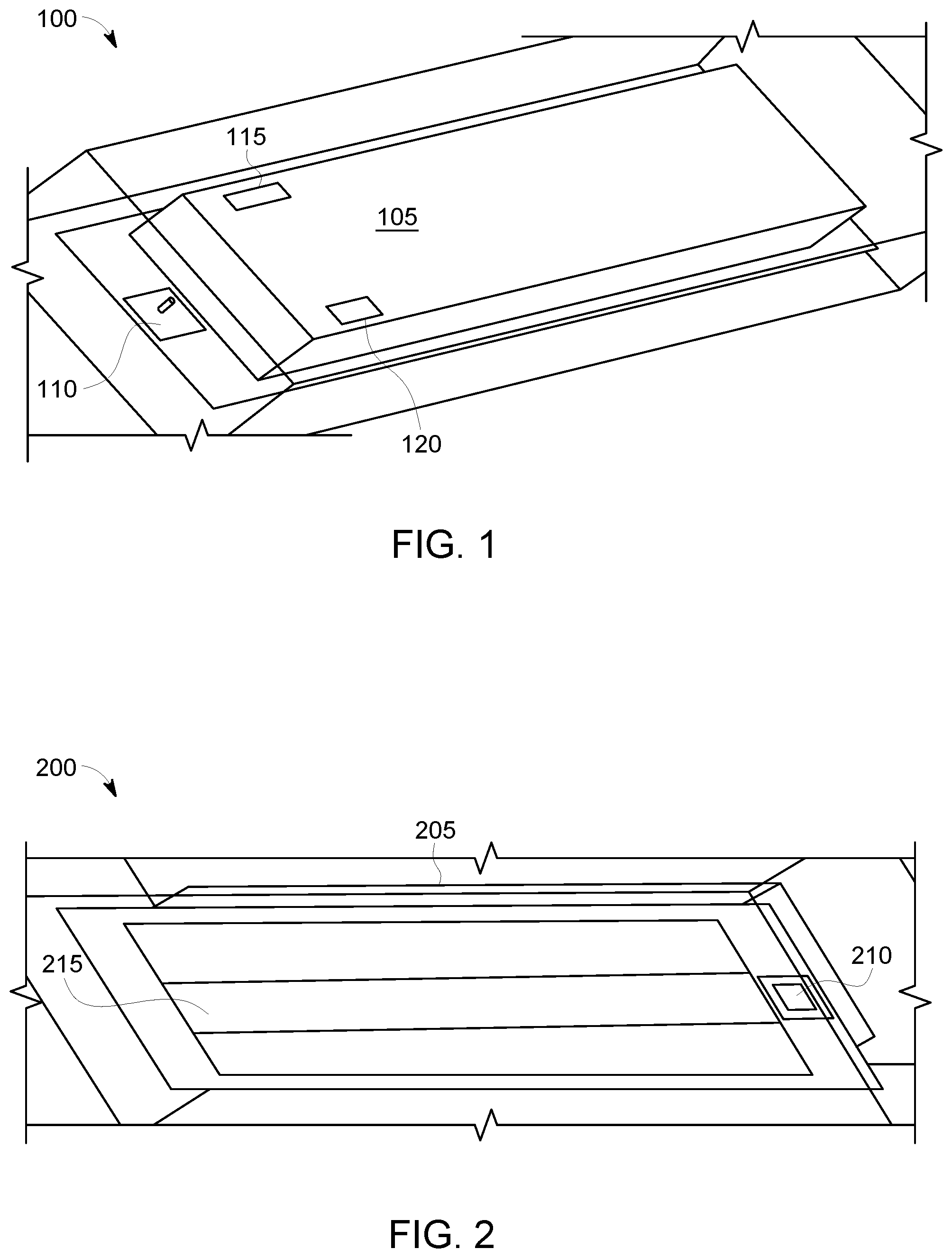
FIG. 1 is an illustrative depiction of a lighting fixture 100, in accordance with some embodiments herein. The lighting fixture 100 shown in FIG. 1 may be designated as a replacement of a T8 fluorescent lamp or other configurations based on its construction and configuration, as understood by those knowledgeable and skilled in the art of lighting. In some embodiments, lighting fixture 100 may include one or more light sources (not shown in FIG. 1). The light sources may be, in some embodiments, solid state light sources such as, for example, light emitting diodes. It will be appreciated by those skilled in the art(s) related hereto that light sources other than those specifically shown in the following discussion and corresponding drawings are within the scope of the present disclosure, to the extent that such light sources are compatible with other aspects of the various embodiments herein.
Lighting fixture 100 includes a housing 105 to enclose, support, and contain the components of the lighting fixture, including mechanical, optical, electrical, and other components of the lighting fixture. In some embodiments herein, lighting fixture 100 includes a radio frequency (RF) transmitter 115. In some aspects herein, RF transmitter 115 is, at least partially, located in or on housing 105. RF transmitter 115 is operative to transmit one or more RF signals. The transmitted RF signal may include, at least, an identifier assigned to the transmitter. In some aspects, the identifier propagated in the RF signal transmitted by RF transmitter 115 may be unique. In some embodiment, the uniqueness of the identifier for a RF transmitter herein may be universal or limited to a particular configuration such as a frequency band, a system configuration, a manufacturer, an identifier format, and other criteria. In some aspects, the identifier communicated in the signal from the RF transmitter may be interpreted to be an identifier for co-located lighting fixture 100. As such, an identifier transmitted by RF transmitter 115 may also be referred to as an identifier for lighting fixture 100. In some aspects, a single RF transmitter is included in each lighting fixture herein. Accordingly, each lighting fixture may have only a single identifier. In a specific embodiment, the identifier may be a sequence of numeric and alphabetic (alphanumeric) characters. In another embodiment, the identifier may be a sequence of digits in base 16 (hexadecimal). It is noted that the unique identifier may be configured and represented in other formats, without any loss of generality herein.
In some embodiments, the transmitted RF signal may have a fixed or adjustable transmit power, a fixed or adjustable transmit frequency, and a fixed or adjustable advertisement interval, in different embodiments. In some aspects, RF transmitter 115 may be configured according to a particular use-case or application being served by the lighting fixture 100. For example, in an indoor positioning system use-case including, for example a retail store setting, RF transmitter 115 may be configured to wirelessly transmit a signal having a frequency of about 2.4 GHz to about 2.485 GHz over short distances via a directional radiating element 110. In some embodiments, the frequency may switch between several channels (e.g. frequency hopping).
Directional radiating element 110 may comprise an antenna. In some embodiments, directional radiating element 110 may be a planar patch antenna. Directional radiating element 110 may comprise configurations other than a patch antenna, however the directional radiating element characteristically directs or shapes in a specific, pre-determined direction and pattern. While the pre-determined direction and pattern of the directional radiating element 110 may depend on the particular configuration of the directional radiating element, the direction and shape of the signal radiated by directional radiating element 110 is not omni-directional. In other words, the direction and shape of the signal radiated by a directional radiating element herein is other than omni-directional. In this manner, the RF signal(s) transmitted by RF transmitter 115 and further shaped and directed in particular direction(s) by antenna 110 may generally be more focused with regard to a distribution of the signal, as compared to a distribution of a similar or same transmitter that is coupled to an omni-directional radiating element.
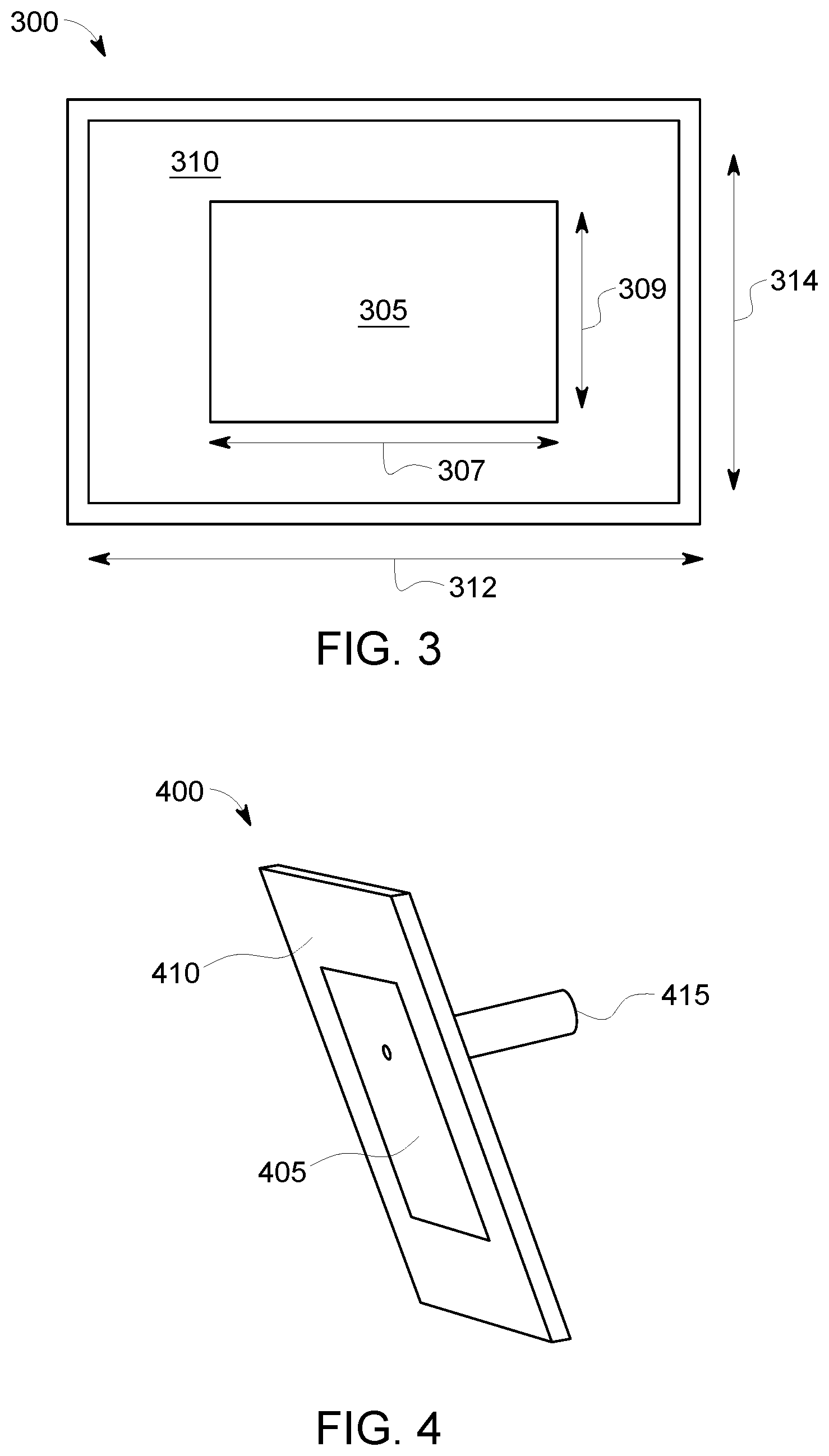
FIG. 2 is an illustrative depiction of a lighting fixture 200. Lighting fixture 200 is shown in a perspective view from a vantage point below the lighting fixture, such as the case where, for example, the lighting fixture 200 is installed on, in, or from a ceiling location above an observer. Lighting fixture 200 includes a housing 205 and a directional radiating element 210, both of which are similar to like items discussed above with respect to FIG. 1. Lighting fixture also includes a light source 215 and a RF transmitter that is not shown in FIG. 2. Light source 215 may comprise one or more sources of illumination, including one or more types thereof without any loss of generality herein. FIG. 3 is an illustrative depiction of a directional radiating element, in accordance with some embodiments herein. In the example of FIG. 3, the directional radiating element comprises a planar patch antenna (i.e., a rectangular microstrip antenna). Patch antenna 300 includes a rectangular "patch" 305 of metal (e.g., copper) having a length 307 and a width 309. Patch antenna also includes a backside ground plane (not shown in FIG. 3) that is obscured by substrate 310. Substrate 310 may be constructed of a dielectric material, including a Polytetrafluoroethylene (PTFE) and other materials. Substrate 310 has a length 312 and a width 314. The dimensions of patch antenna 300 may be sized to optimize and/or match the frequency of the signal(s) fed to the antenna. For example, for a Bluetooth signal the patch antenna may have the following dimensions: 307=48 mm, 309=40.5 mm, 312=82 mm, and 314=70 mm. In some embodiments, the patch is about one-half wavelength long. In some regards, the sizes of the patch may be varied and changed due to the dielectric constant and thickness of substrate 310.
In some embodiments, patch antenna 300 radiates a linearly polarized wave. It is known that when electromagnetic signals encounter a boundary between two media with different refractive indices, some of the signals will usually be reflected. The fraction of the signals that is reflected is described by the Fresnel equations and is dependent upon the incoming signal's polarization and angle of incidence. The angle of incidence at which the signal with a particular polarization is perfectly transmitted through a dielectric surface (i.e., with no reflection) is referred to as Brewster's angle or the polarization angle. Based on this knowledge and the polarization of the directional antennas herein, the antennas may ideally be positioned at a location where the reflections from one beacon will not interfere with itself (i.e., zero reflections). In some applications and use-cases, the lighting fixtures disclosed herein with directional radiating antennas may be positioned such that the antennas therein transmit their signals at the Brewster's angle or close thereto in an effort to eliminate or at least minimize reflections by signals from the antenna.
FIG. 4 is a perspective view of a patch antenna 400, in accordance with some aspects herein. Patch antenna 400 includes, inter alia, a metal patch 405, a substrate 410, and a ground plane (not shown). Additionally, a feed patch antenna 400 includes a feedline 415.
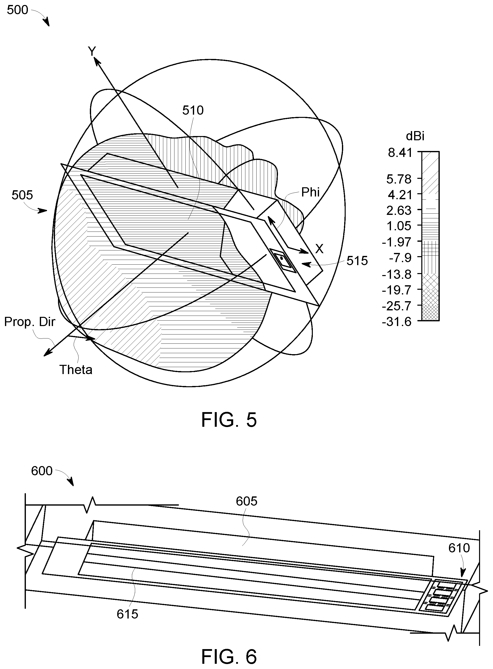
FIG. 5 is a depiction 500 of an antenna radiation pattern, in accordance with some embodiments herein. FIG. 5 shows a radiation distribution pattern 505 for a RF signal (RF frequency=2.45 GHz) shaped by an antenna 515 co-located with lighting fixture 510. The gain of the patch antenna across the distribution is conveyed by the variations in the shading of radiation pattern 505.
FIG. 6 is an illustrative depiction of a lighting fixture 600, in accordance with some embodiments herein. Lighting fixture 600 includes a housing 605 that encloses, houses, or supports a light source 615 and an array 610 of a plurality of directional radiating elements. The array of directional radiating elements may include patch antennas similar to those shown in FIGS. 2-4. In the example of FIG. 6, the array of antennas includes four (4) patch antennas coupled to one RF transmitter. The antennas may be placed about one-half wavelength apart to create a "broadside array" that generates a very strong signal in the direction perpendicular to the array, in the direction below the lighting fixture. For the sake of clarity, other components of lighting fixture 600 are not shown in FIG. 6.
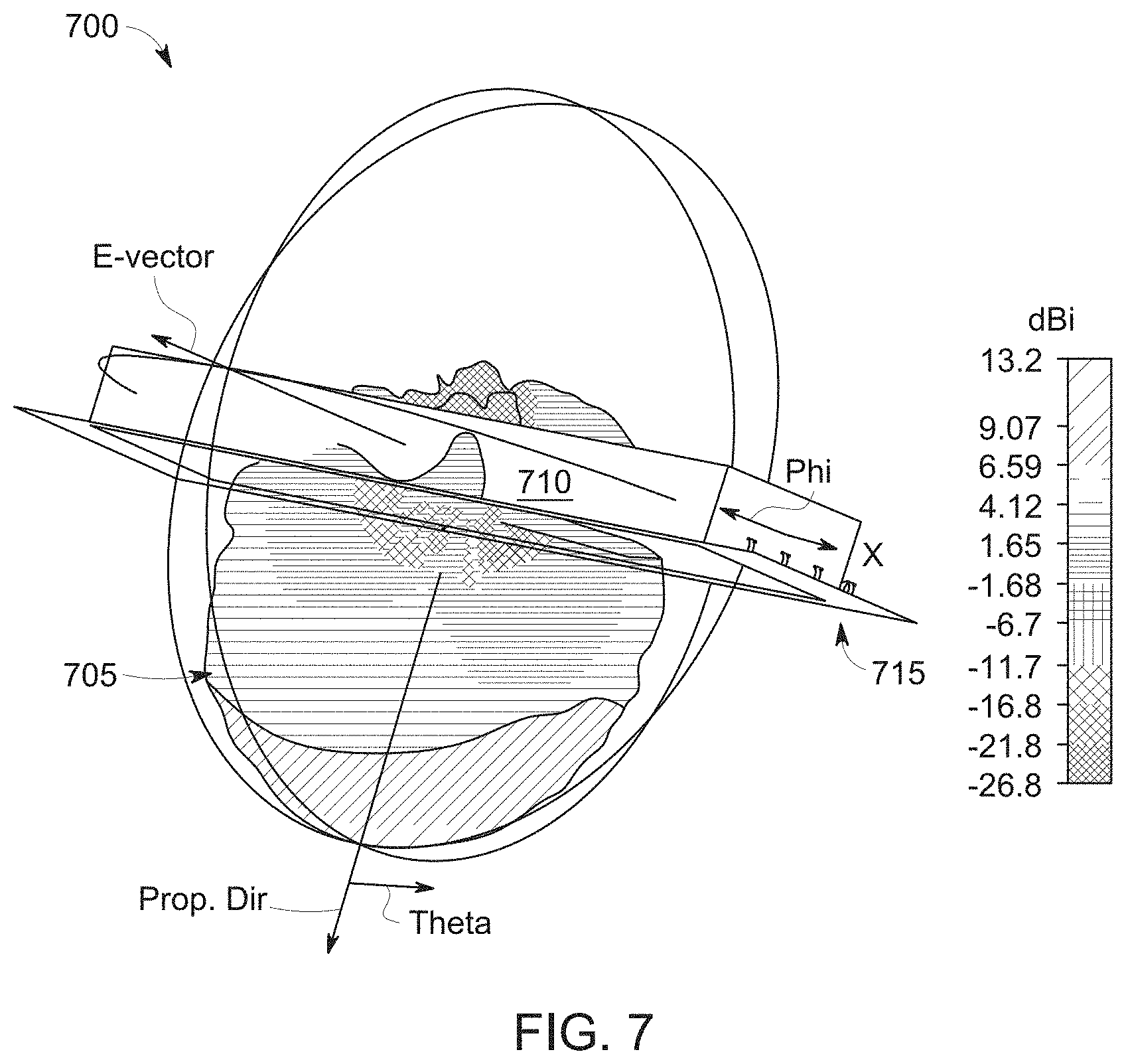
Array 610 comprising the plurality of directional radiating elements may include patch antennas where the signals radiating by each patch antenna of the array cooperate or otherwise interact with each to produce a signal having a higher gain than the single patch antenna configuration. FIG. 7 is a depiction 700 of an antenna radiation pattern, in accordance with some embodiments herein. FIG. 7 shows a radiation distribution pattern 705 for a RF signal (RF frequency=2.45 GHz) shaped by an array 715 of antennas co-located with lighting fixture 710. The gain of the patch antennas across the distribution is conveyed by the variations in the shading of radiation pattern 705.
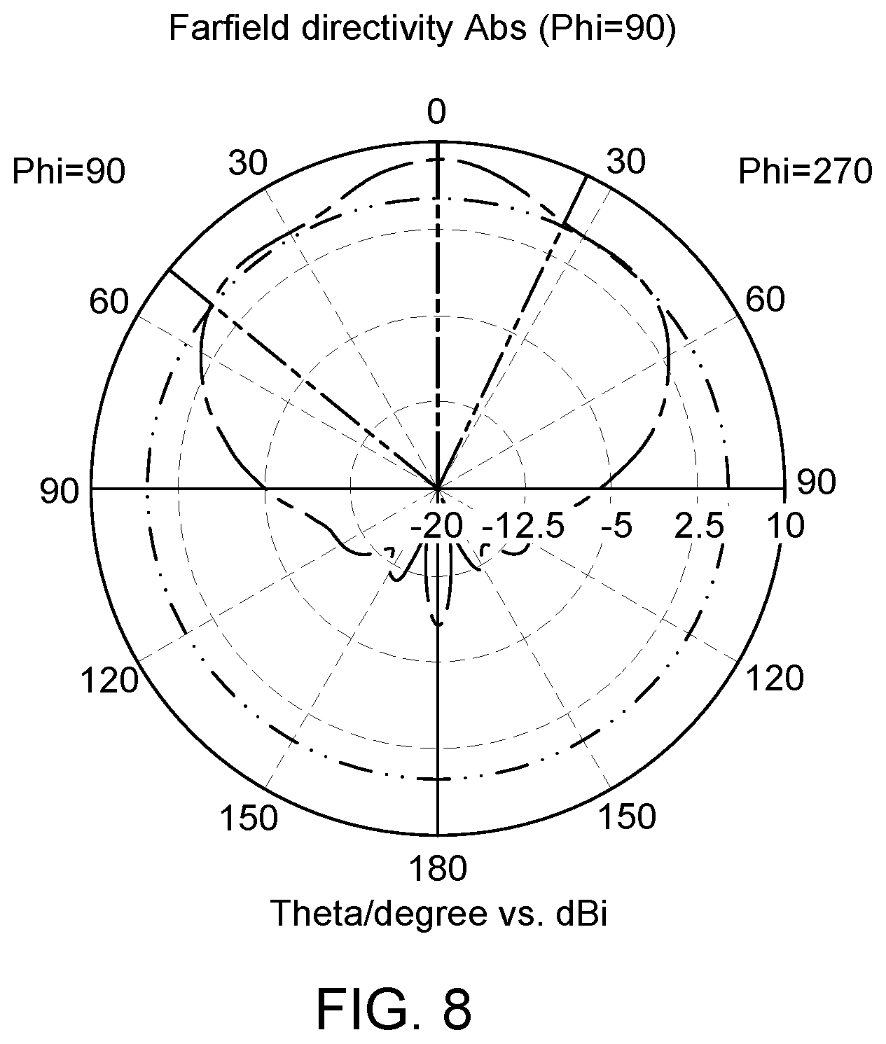
FIGS. 8 and 9 are illustrative representations of the radiation distribution for a lighting fixture herein having a single patch antenna and an array of patch antennas, respectively, in accordance with some aspects herein. As shown, the radiation pattern on FIG. 9 is more focused than the radiation pattern of FIG. 8. As will be discussed in greater below, a more focused radiation pattern by a lighting fixture herein may facilitate a greater location determining functionality.
In some embodiments, the RF transmitter and antennas comprising a lighting fixture herein may be integrated into a common component or module or packaged as separate modules.
FIG. 10 is an illustrative block diagram depiction of a system 1000, in accord with some aspects and embodiments herein. System 1000 includes a plurality of lighting fixtures 1010-1085 located within a facility 1005. Each of the lighting fixtures shown in FIG. 10 may include a housing and a light source, a RF transmitter, and a directional radiating element within the housing as discussed hereinabove. In an effort to maintain clarity, the various components comprising each of the lighting fixtures 1010-1085 are not shown in FIG. 10 since a full disclosure of such is presented above. In some embodiments, the arrangement, configuration or location of lighting fixtures 1010-1085 is known by an entity such as a service provider, a system administration, or other entity. In some embodiments, the location of the individual lighting fixtures 1010-1085 may be known relative to a universal coordinate or position system (e.g., latitude and longitude coordinates), relative to one or more other objects having a known location or relative to each other.
In accordance with other aspects herein, each of the lighting fixtures 1010-1085 includes a directional radiating element or antenna (not shown in FIG. 10) that directs a signal transmitted by the included RF transmitter primarily and substantially downward and away from the lighting fixture when the lighting fixture is disposed in, on, or supported by a ceiling of facility 1005. In accordance with some methods and process herein, lighting fixtures 1010-1085 are each operative to transmit a signal including an indication of the identifier associated with its RF transmitter (and by extension the light fixture) in a predefined direction away from the light fixture. In some embodiments, the directional radiating element or antenna of each lighting fixture directs its RF signal substantially downward, away from, and primarily directly below the lighting fixture when the lighting fixture is disposed in, on, or supported by the ceiling(s) of facility 1005. Furthermore, a mobile receiver configured to detect, receive, and process the signals transmitted by lighting fixtures 1010-1085 may receive the signals when the receiver is operational and in the vicinity of the lighting fixtures.
As used herein, the term "vicinity" refers to an area within the range of the signal(s) transmitted by the lighting fixtures herein. Accordingly, the actual "vicinity" for a particular embodiment may be dependent on the range of the RF transmitter of the lighting fixtures. Other factors may, in some contexts and configurations, also impact the effective definition of the "vicinity" of the lighting fixtures since other factors such as signal reflections and interference can impact the effective range of transmitted signals and/or their reception by a receiver.
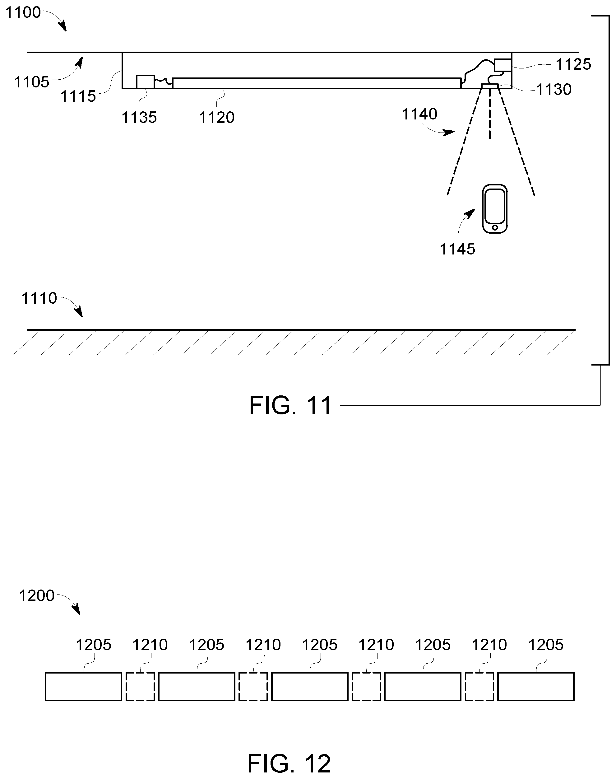
FIG. 11 is an illustration of an indoor environment or facility 1100 that may include one or more lighting fixtures, in accordance with some embodiments herein. Facility 1100 may be any indoor space in some regards. Facility 1100 includes a ceiling 1105 and a floor 1110 with a lighting fixture 1102 disposed on, in, or supported by the ceiling. Lighting fixture 1102 includes a housing 1115 that houses a light source 1120, a RF transmitter 1125, and a directional radiating element 1130 that are operationally functional as described above. Lighting fixture 1102 further includes a power source 1135 that is configured to operatively provide sufficient power to energize and power the components of the lighting fixture as appropriate. For example, power source 1135 may provide power to energize light source 1120 and RF transmitter 1125, either directly or indirectly and with the appropriate currents and/or voltages. Accordingly, a need to provide a separate power supply for the RF transmitter herein may be avoided. Lighting fixture 1102 is further configured to include the requisite wiring and interconnects between the components thereof, including electrical wiring, interconnects, and RF line feeds (not individually labeled in FIG. 11).
As illustrated by the dashed lines in FIG. 11, the RF signal transmitted by RF transmitter 1125 is directed primarily downward and away from the lighting fixture 1102 to a location substantially underneath the lighting fixture. As such, signal 1140 may be received by a mobile device 1145 that is configured to detect, receive, and process the signal. In some aspect, mobile device 1145 may comprise a mobile phone (e.g., a smartphone) or other device having functionality to detect, receive, and process signal 1140. The functionality to detect, receive, and process signal 1140 by mobile device as it traverses facility 1100 (and 1200) may be implemented by hardware (e.g., an antenna, a transceiver, etc.), software (e.g., firmware, an application or "app", etc.) and a combination thereof.
In another embodiment herein, the antenna may be integrated with an extension module. As referred to herein, an extension module can be an electrical, mechanical, or electro-mechanical device that may be connected to one or more individual fixtures through, generally, mechanical and electrical connection(s) located on the lighting fixture(s). In some embodiments, an extension module may be connected to one individual lighting fixture. In some embodiments, one or more devices, systems, and sensors may be attached to or housed in or on an extension module. In some embodiments, an extension module can connect two light fixtures such as, for example, two light fixtures in a row of light fixtures assembled on a ceiling. The antenna integrated in an extension module may be in the shape of a helix (i.e., a helical antenna) or a yagi antenna that fits within the inner confines of the extension module. In some embodiments, the helical antenna may have a higher gain than a single planar antenna. In the instance the antenna is integrated with an extension module, the RF transmitter may also be integrated to the extension module. FIG. 12 is an illustrative depiction of a row of lighting fixtures where a plurality of lighting fixtures 1205 have an extension module 1210 joining pairs of the lighting fixtures to each other. In accordance with some aspects herein, a directional radiating element (i.e., antenna) may be integrated into the extension module.
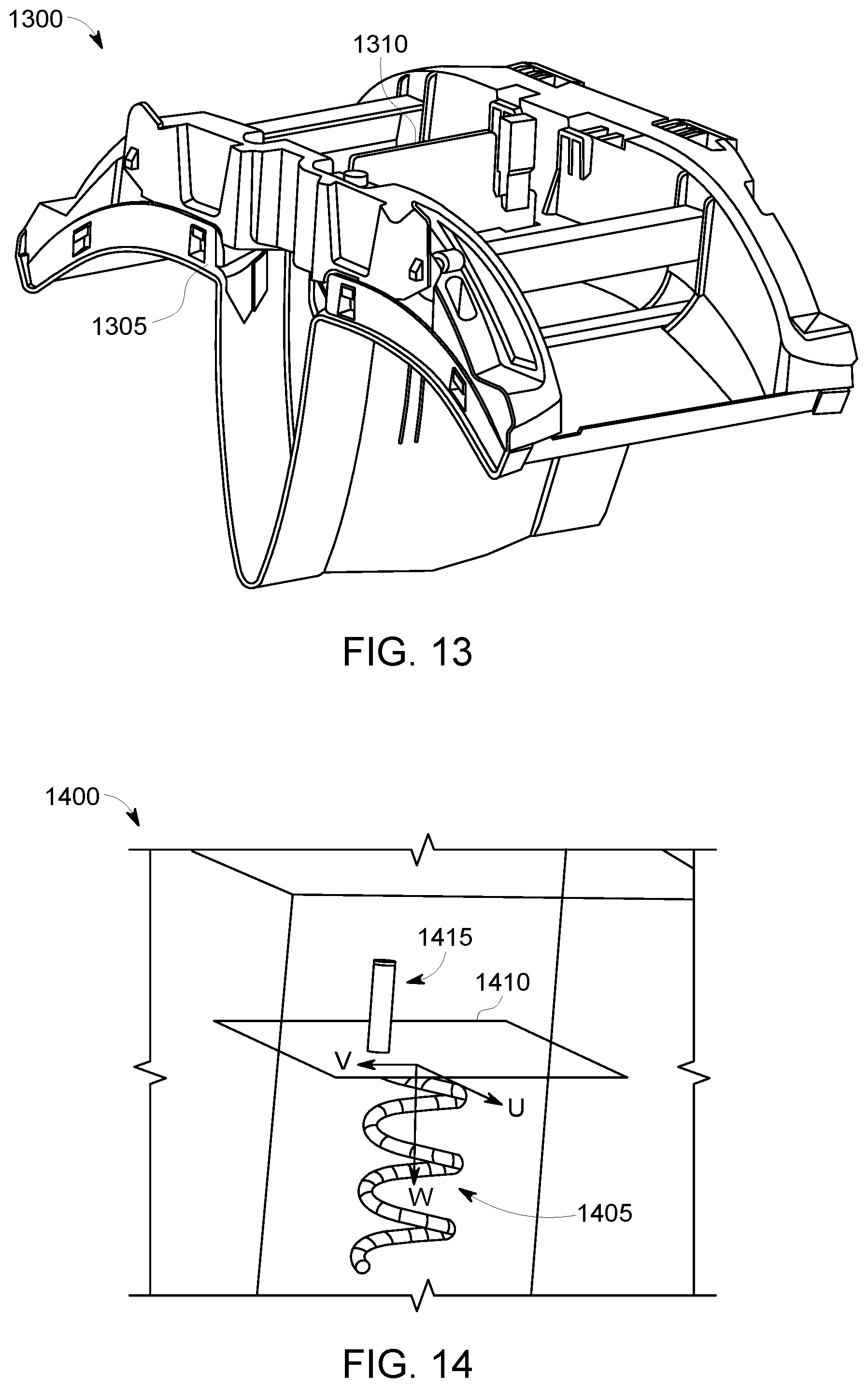
FIG. 13 is an illustrative rendering of an extension module 1300 for a lighting fixture including some embodiments herein. As shown extension module has a housing 1305 sized and configured to matingly attach to a lighting fixture at the distal ends thereof. Moreover, extension 1300 includes a PCB 1310 including an antenna (e.g., antenna, yagi antenna, and other types and configurations of antennas) and a RF transmitter.
FIG. 14 is an illustrative depiction of a helical antenna 1400. In particular, helical antenna 1400 includes a helix 1405, a ground plane 1410, and a feed line 1415.
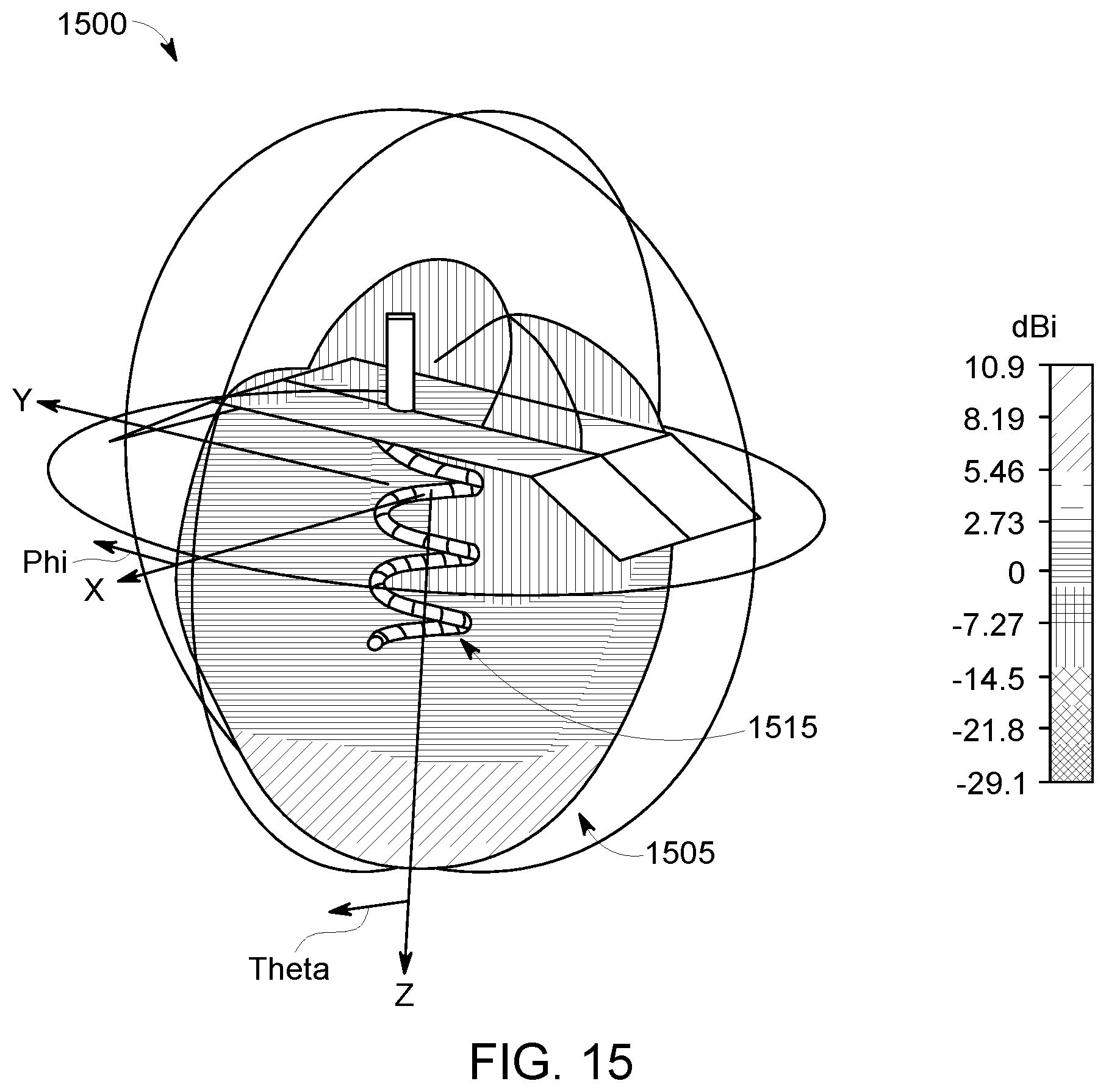
FIG. 15 is a depiction 1500 of an antenna radiation pattern, in accordance with some embodiments herein. FIG. 15 shows a radiation distribution pattern 1505 for a RF signal shaped by a helical antenna 1515 that can be co-located with a lighting fixture herein. The gain of the helical antenna across the distribution is conveyed by the variations in the shading of radiation pattern 1505.
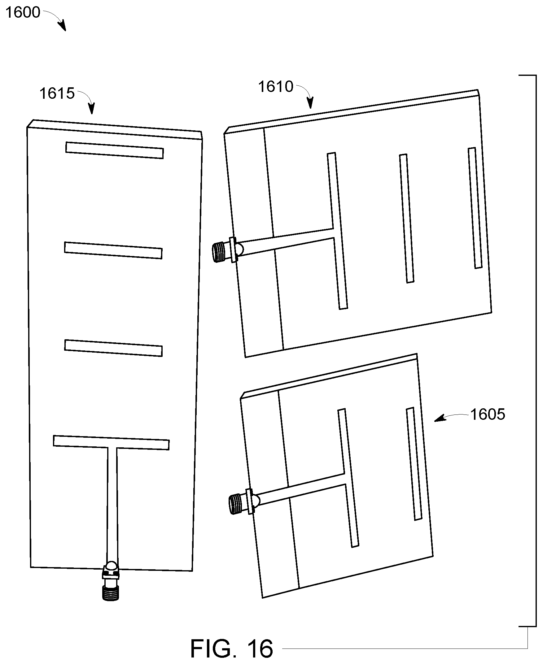
FIG. 16 is an illustrative depiction 1600 of a number of Yagi antennas that may be incorporated into the lighting fixtures disclosed herein. Yagi antenna 1605 includes a single dipole or director element, antenna 1610 has two dipoles, and antenna 1615 includes three dipoles or director elements. Regarding the radiation pattern and gain of the Yagi antennas, Applicant(s) realized adding 3 directors did not significantly improve the radiation parameter as much as the switch from the one director Yagi antenna to the two director Yagi antenna. Taking into account the smaller size, the Yagi antenna with two directors may be considered the relative best choice. In some aspects, it is noted that one benefit of the Yagi type antenna is that their parameters do not depend much on the substrate used.
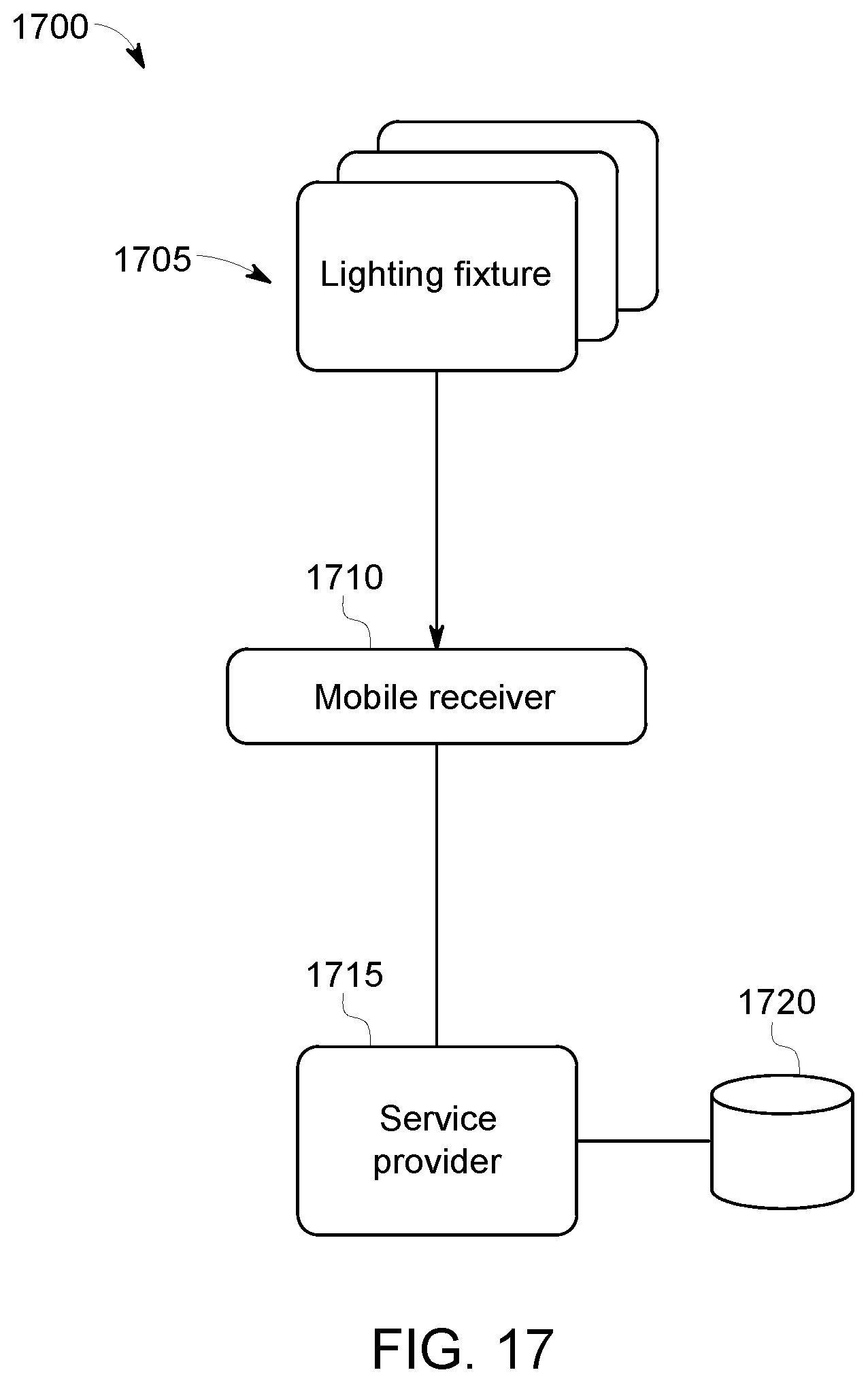
FIG. 17 is an illustrative depiction of a system 1700, in accordance with some embodiments herein. System 1700 includes a plurality of lighting fixtures 1705 where each directionally transmits a signal including an identifier for the lighting fixture. System 1700 further includes a receiver 1710 for functionality detecting, receiving, and processing the transmitted signal from the lighting fixture. An entity such as a service provider 1715 can communicate with receiver 1710 to provide or support processing of the signal or representations thereof by the receiver. In some aspects, receiver 1710 may provide an identifier included in the signal(s) it receives and service provider can determine the location of the lighting fixture based, at least in part, on the identifier it received in a transmission from the receiver. The receiver and servicer provider may communicate in real-time as receiver 1710 moves about a facility (e.g., 1000 and 1100) and receives signals from light fixtures. Receiver 1710 may operate to detect and receive a signal and determine its signal strength. Based on the signal strength of the signal(s) received at receiver 1710, either as an absolute strength or as a relative strength compared to other relevant signals it may also be receiving, receiver 1710 may determine it is most closely located in the vicinity of a particular lighting fixture. The unique identifier included in the signal determined to be indicative of the lighting fixture most closely located to the receiver can be noted and retained in a record or other signal. The receiver and/or the service provider 1715 can use the identifier associated with the lighting fixture determined to be closest to the receiver to determine a location of the receiver (and by extension its user) within a facility (e.g., 1000 or 1100). Service provider 1715 may include a processor for processing information and executing instructions to provide its functionality and a storage facility 1720. Storage facility 1720 may comprise a database including one or more nodes and organizing data using a variety of data structures and schemas, without limits herein. In some embodiments, a mapping of the receiver within the facility can be provided by the receiver and/or service provider 1715. The mapping functionality may be facilitated by data stored on receiver 1710, storage facility 1720, and third-party service providers (not shown in FIG. 17) that receiver 1710 and/or service provider 1715 may communicate with.
In some embodiments, maps may be downloaded to the mobile device or receiver 1710 for location determinations and/or mappings performed by the mobile receiver. In some embodiments, the mobile receiver detects the signals transmitted by the lighting fixtures and sends the unique identifier of the strongest signal (i.e., the closest lighting fixture due to the focused directional characteristic radiation of the lighting fixtures herein) to the service provider 1715. The service provider 1715 may then determine the location of the mobile receiver and send a representation of a map showing the mobile receiver's location to the mobile receiver 1710.
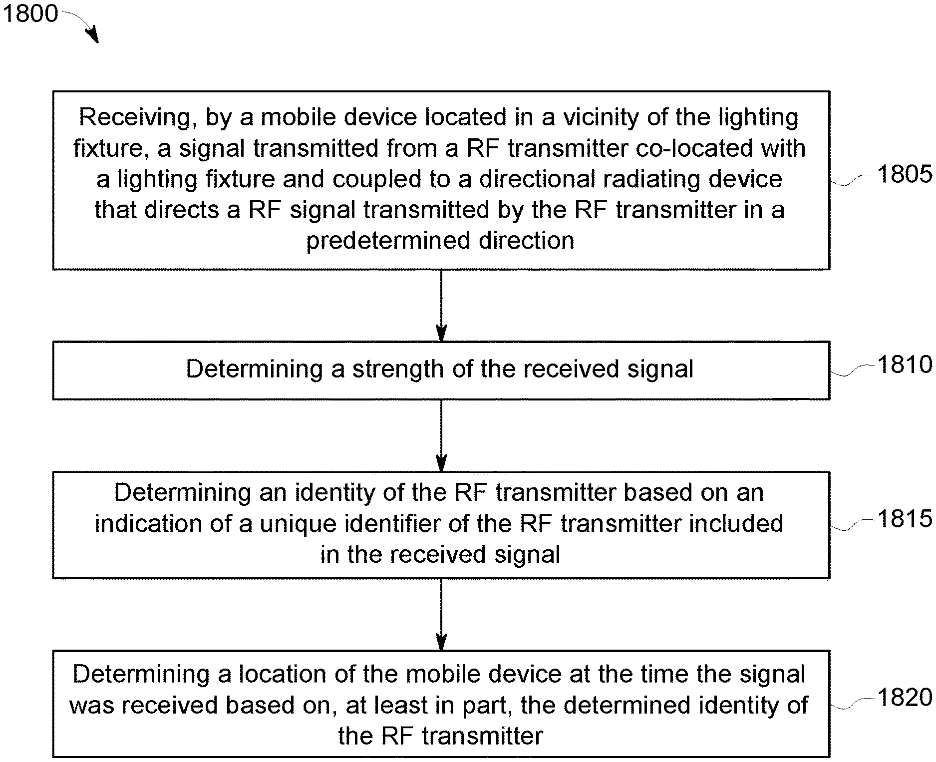
FIG. 18 is an illustrative depiction of a flow diagram for a process 1800. Process 1800 may be implemented by software components, hardware components, and a combination thereof, including systems such as those shown in FIGS. 11, 12, and 17.
In some embodiments and prior to operation 1805, a facility may be outfitted with one or more lighting fixtures configured as disclosed herein. Part of the outfitting may include obtaining and recording the specific installation location of each of the plurality of lighting fixtures. Additionally, the radiating pattern of the RF transmitter and directional radiating element combination for each lighting fixture will also be determined, obtained, or otherwise known. In some embodiments, a mapping (ie., coordinates) of the lighting fixtures may be determined. The mapping of the lighting fixtures may be established in a record. The mapping of the lighting fixtures may be represented in a tabular or graphical representation of the facility. One or more of the information concerning the location of the lighting fixtures, the radiation pattern(s) of the lighting fixtures, the identifiers of the plurality of lighting fixtures, the mapping of the location of the plurality of lighting fixtures, and other information may be maintained in a one or more records or other data structures and stored by a mobile receiver (e.g., 1710), a service provider (e.g., 1715), and combinations thereof.
Process 1800 includes an initial operation of receiving a signal transmitted from a RF transmitter that is co-located with a lighting fixture by a mobile receiver in the vicinity of the lighting fixture. The lighting fixture itself includes a directional radiating element such as a patch antenna to shape and direct the RF signal in a predetermined direction.
Process 1800 continues at operation 1810 where a determination of the signal received by the mobile receiver is executed. The strength of the received signal is determined in an effort for the receiver to determine the lighting fixture to which it is closest located. In some embodiments, a signal below a predetermined threshold may be disregarded. That is, the received signal must have a minimum strength at the receiver. In some embodiments, this minimum threshold may be determined and based on a number of factors, including but not limited to the configuration of a plurality of lighting fixtures within a facility, a strength of the signals transmitted by the disposed lighting fixtures, a sensitivity of the mobile receiver or an expected (average) sensitivity thereof, the physical configuration of the deployed system (e.g., ceiling height, height of directional radiating element of the installed lighting fixtures, expected (average) height of a mobile receiver in the facility, other considerations, and combinations thereof. For example, a received signal greater than -50 dBm may indicate the mobile receiver is directly below a lighting fixture and a signal less than about -60 dBm may indicate that the mobile receiver is about 2 meters away from the lighting fixture.
At operation 1815, an identity of the RF transmitter associated with the signal determined at operation 1810 to be closest to the receiver is determined. The identity of the RF transmitter is based on an indication of the RF transmitter's unique identity that is included in the received signal. The unique identifier may be included in a data packet transmitted with the RF signal.
Process 1800 continues to operation 1820 where a location of the mobile device receiver at the time the signal was received is determined. The location determination of operation 1820 may be based, at least in part, on the identity of the RF transmitter (and by extension the lighting fixture) determined at operation 1815. The location thus determined may be communicated to a user of the mobile device receiver in a textual or graphical representation. In a graphical representation, the location of the mobile device may be shown as an icon or other marker overlaid on a graphical representation of the facility housing the lighting fixture.
In some aspects, including a context including a smaller building/facility and other scenarios, an operation of a process for determining a location of a receiver in the a facility including one or more lighting fixtures may include downloading a map with locations of the lighting fixtures to the mobile receiver device so that the location of the mobile device may be determined by the mobile device.
In some embodiments, RF signals transmitted from multiple devices may be used to accurately determine a position of a mobile device receiving the RF signals. For example, the mobile receiver device may use a form of triangulation to process the multiple RF signals to determined its position.
In some embodiments, a location determined for a mobile receiver device herein may be used in conjunction with a service, application, or process to provide an additional service or other functionality. For example, the determined location may be used by a location-based service to provide coupons and/or advertisements in real-time to a user via their mobile device as they traverse a retail location outfitted with lighting fixtures having RF transmitters as disclosed herein.
All systems and processes discussed herein may be embodied in program code stored on one or more tangible, non-transitory computer-readable media. Such media may include, for example, a floppy disk, a CD-ROM, a DVD-ROM, a Flash drive, magnetic tape, and solid state Random Access Memory (RAM) or Read Only Memory (ROM) storage units. Embodiments are therefore not limited to any specific combination of hardware and software.
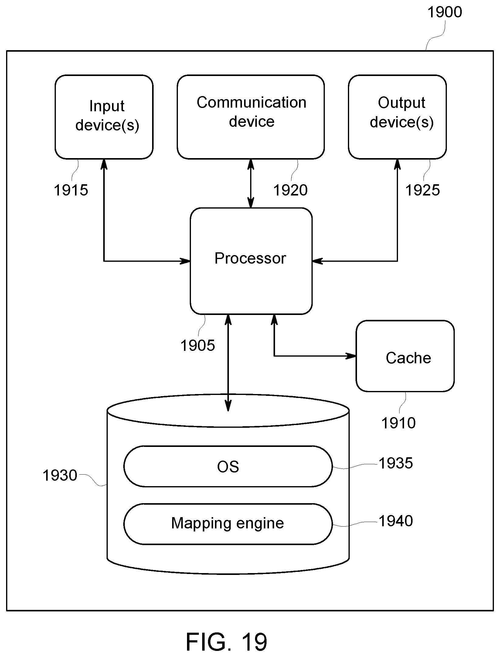
FIG. 19 is an illustrative depiction of a system, apparatus, or device that may be used to, for example, implement one or more of the logical descriptions of abstractions of FIG. 13. FIG. 19 is a block diagram of a computing device or machine, in accordance with some embodiments. System 1900 may be, for example, associated with devices for implementing the processes disclosed herein, including the disclosed indoor positioning system process(es). System 1900 comprises a processor 1905, such as one or more commercially available Central Processing Units (CPUs) in the form of one-chip microprocessors or a multi-core processor, coupled to a communication device 1920 configured to communicate via a communication network (not shown in FIG. 19) to another device or system (e.g., a mobile device receiver). System 1900 may also include a cache 1910, such as RAM memory modules. The system may further include an input device 1915 (e.g., a touchscreen, mouse and/or keyboard to enter content) and an output device 1925 (e.g., a touchscreen, a computer monitor to display, a LCD display). In some embodiments, system 1900 may perform at least some of the functions associated with one or more of the logical descriptions and abstractions of FIG. 13.
Processor 1905 communicates with a storage device 1930. Storage device 1930 may comprise any appropriate information storage device, including combinations of magnetic storage devices (e.g., a hard disk drive), optical storage devices, solid state drives, and/or semiconductor memory devices. In some embodiments, storage device 1930 may comprise a database system, including in some configurations an in-memory database.
Storage device 1930 may store program code or instructions to control an operation of a computing device (e.g., system 1900) to perform mobile device location determination and mapping functions, in accordance with processes herein. Processor 1905 may perform the instructions for implementing, for example, process 11900 in accordance with any of the embodiments described herein. Program instructions for determining a location for a mobile device in a indoor facility executed by a mapping engine 1940 may be provided, as well as other program elements, such as an operating system 1935. Storage device 1930 may also include data used by system 1900, in some aspects, in performing one or more of the processes herein, including individual processes, individual operations of those processes, and combinations of the individual processes and the individual process operations.
Although embodiments have been described with respect to certain contexts, some embodiments may be associated with other types of devices, systems, and configurations, either in part or whole, without any loss of generality. For example, in some embodiments, a yagi antenna may be used to radiate signals parallel to the antenna. In some such embodiments, the antenna may be housed in separate module where the module is positioned to take advantage of the radiation pattern of the yagi antenna.
Embodiments have been described herein solely for the purpose of illustration. Persons skilled in the art will recognize from this description that embodiments are not limited to those described, but may be practiced with modifications and alterations limited only by the spirit and scope of the appended claims.
* * * * *
D00000
D00001
D00002
D00003
D00004
D00005
D00006
D00007
D00008
D00009
D00010
D00011
D00012

D00013
XML
uspto.report is an independent third-party trademark research tool that is not affiliated, endorsed, or sponsored by the United States Patent and Trademark Office (USPTO) or any other governmental organization. The information provided by uspto.report is based on publicly available data at the time of writing and is intended for informational purposes only.
While we strive to provide accurate and up-to-date information, we do not guarantee the accuracy, completeness, reliability, or suitability of the information displayed on this site. The use of this site is at your own risk. Any reliance you place on such information is therefore strictly at your own risk.
All official trademark data, including owner information, should be verified by visiting the official USPTO website at www.uspto.gov. This site is not intended to replace professional legal advice and should not be used as a substitute for consulting with a legal professional who is knowledgeable about trademark law.