Methods, systems, and apparatuses for tracking ablation devices and generating lesion lines
Viswanathan November 24, 2
U.S. patent number 10,842,572 [Application Number 16/785,392] was granted by the patent office on 2020-11-24 for methods, systems, and apparatuses for tracking ablation devices and generating lesion lines. This patent grant is currently assigned to Farapulse, Inc.. The grantee listed for this patent is Farapulse, Inc.. Invention is credited to Raju Viswanathan.


View All Diagrams
| United States Patent | 10,842,572 |
| Viswanathan | November 24, 2020 |
Methods, systems, and apparatuses for tracking ablation devices and generating lesion lines
Abstract
Systems, devices, and methods for electroporation ablation therapy are disclosed. An apparatus may be configured to activate a field generator to generate an electric or magnetic field such that signals are received by a receiver coupled to an ablation device disposed adjacent to a tissue surface. Processed data associated with the signals may be obtained. A position and an orientation of the ablation device may be determined based on the processed data. An expected ablation zone of the ablation device in the tissue surface may be determined based on the position and the orientation of the ablation device. A map of the tissue surface and a visual representation of the expected ablation zone disposed in the map of the tissue surface may be displayed.
| Inventors: | Viswanathan; Raju (Mountain View, CA) | ||||||||||
|---|---|---|---|---|---|---|---|---|---|---|---|
| Applicant: |
|
||||||||||
| Assignee: | Farapulse, Inc. (Menlo Park,
CA) |
||||||||||
| Family ID: | 1000004690133 | ||||||||||
| Appl. No.: | 16/785,392 | ||||||||||
| Filed: | February 7, 2020 |
Related U.S. Patent Documents
| Application Number | Filing Date | Patent Number | Issue Date | ||
|---|---|---|---|---|---|
| 62940219 | Nov 25, 2019 | ||||
| Current U.S. Class: | 1/1 |
| Current CPC Class: | A61B 90/36 (20160201); A61B 18/1492 (20130101); A61B 18/1206 (20130101); A61B 34/20 (20160201); A61B 34/10 (20160201); A61B 2034/2074 (20160201); A61B 2018/00577 (20130101); A61B 2018/00738 (20130101); A61B 2034/107 (20160201); A61B 2034/102 (20160201); A61B 2090/367 (20160201) |
| Current International Class: | A61B 18/14 (20060101); A61B 18/12 (20060101); A61B 34/20 (20160101); A61B 34/10 (20160101); A61B 90/00 (20160101); A61B 18/00 (20060101) |
References Cited [Referenced By]
U.S. Patent Documents
| 4200104 | April 1980 | Harris |
| 4438766 | March 1984 | Bowers |
| 4470407 | September 1984 | Hussein |
| 4739759 | April 1988 | Rexroth et al. |
| 5234004 | August 1993 | Hascoet et al. |
| 5242441 | September 1993 | Avitall |
| 5257635 | November 1993 | Langberg |
| 5281213 | January 1994 | Milder et al. |
| 5304214 | April 1994 | DeFord et al. |
| 5306296 | April 1994 | Wright et al. |
| 5334193 | August 1994 | Nardella |
| 5341807 | August 1994 | Nardella |
| 5342301 | August 1994 | Saab |
| 5398683 | March 1995 | Edwards et al. |
| 5443463 | August 1995 | Stern et al. |
| 5454370 | October 1995 | Avitall |
| 5515848 | May 1996 | Corbett, III et al. |
| 5531685 | July 1996 | Hemmer et al. |
| 5545161 | August 1996 | Imran |
| 5558091 | September 1996 | Acker et al. |
| 5578040 | November 1996 | Smith |
| 5617854 | April 1997 | Munsif |
| 5624430 | April 1997 | Eton et al. |
| 5662108 | September 1997 | Budd et al. |
| 5667491 | September 1997 | Pliquett et al. |
| 5672170 | September 1997 | Cho |
| 5700243 | December 1997 | Narciso, Jr. |
| 5702438 | December 1997 | Avitall |
| 5706823 | January 1998 | Wodlinger |
| 5722400 | March 1998 | Ockuly et al. |
| 5722402 | March 1998 | Swanson et al. |
| 5749914 | May 1998 | Janssen |
| 5779699 | July 1998 | Lipson |
| 5788692 | August 1998 | Campbell et al. |
| 5810762 | September 1998 | Hofmann |
| 5833710 | November 1998 | Jacobson |
| 5836874 | November 1998 | Swanson et al. |
| 5836942 | November 1998 | Netherly et al. |
| 5836947 | November 1998 | Fleischman et al. |
| 5843154 | December 1998 | Osypka |
| 5849028 | December 1998 | Chen |
| 5863291 | January 1999 | Schaer |
| 5868736 | February 1999 | Swanson et al. |
| 5871523 | February 1999 | Fleischman et al. |
| 5876336 | March 1999 | Swanson et al. |
| 5885278 | March 1999 | Fleischman et al. |
| 5895404 | April 1999 | Ruiz |
| 5899917 | May 1999 | Edwards et al. |
| 5904709 | May 1999 | Arndt et al. |
| 5916158 | June 1999 | Webster, Jr. |
| 5916213 | June 1999 | Haissaguerre et al. |
| 5921924 | July 1999 | Avitall |
| 5928269 | July 1999 | Alt |
| 5928270 | July 1999 | Ramsey, III |
| 6002955 | December 1999 | Willems et al. |
| 6006131 | December 1999 | Cooper et al. |
| 6009351 | December 1999 | Flachman |
| 6014579 | January 2000 | Pomeranz et al. |
| 6029671 | February 2000 | Stevens et al. |
| 6033403 | March 2000 | Tu et al. |
| 6035238 | March 2000 | Ingle et al. |
| 6045550 | April 2000 | Simpson et al. |
| 6068653 | May 2000 | LaFontaine |
| 6071274 | June 2000 | Thompson et al. |
| 6071281 | June 2000 | Burnside et al. |
| 6074389 | June 2000 | Levine et al. |
| 6076012 | June 2000 | Swanson et al. |
| 6090104 | July 2000 | Webster, Jr. |
| 6096036 | August 2000 | Bowe et al. |
| 6113595 | September 2000 | Muntermann |
| 6119041 | September 2000 | Pomeranz et al. |
| 6120500 | September 2000 | Bednarek et al. |
| 6146381 | November 2000 | Bowe et al. |
| 6164283 | December 2000 | Lesh |
| 6167291 | December 2000 | Barajas et al. |
| 6171305 | January 2001 | Sherman |
| 6216034 | April 2001 | Hofmann et al. |
| 6219582 | April 2001 | Hofstad et al. |
| 6223085 | April 2001 | Dann et al. |
| 6231518 | May 2001 | Grabek et al. |
| 6245064 | June 2001 | Lesh et al. |
| 6251107 | June 2001 | Schaer |
| 6251128 | June 2001 | Knopp et al. |
| 6270476 | August 2001 | Santoianni et al. |
| 6272384 | August 2001 | Simon et al. |
| 6287306 | September 2001 | Kroll et al. |
| 6314963 | November 2001 | Vaska et al. |
| 6322559 | November 2001 | Daulton et al. |
| 6350263 | February 2002 | Wetzig et al. |
| 6370412 | April 2002 | Armoundas et al. |
| 6391024 | May 2002 | Sun et al. |
| 6447505 | September 2002 | McGovern et al. |
| 6464699 | October 2002 | Swanson |
| 6470211 | October 2002 | Ideker et al. |
| 6502576 | January 2003 | Lesh |
| 6503247 | January 2003 | Swartz et al. |
| 6517534 | February 2003 | McGovern et al. |
| 6527724 | March 2003 | Fenici |
| 6527767 | March 2003 | Wang et al. |
| 6592581 | July 2003 | Bowe |
| 6595991 | July 2003 | Tollner et al. |
| 6607520 | August 2003 | Keane |
| 6623480 | September 2003 | Kuo et al. |
| 6638278 | October 2003 | Falwell et al. |
| 6666863 | December 2003 | Wentzel et al. |
| 6669693 | December 2003 | Friedman |
| 6702811 | March 2004 | Stewart et al. |
| 6719756 | April 2004 | Muntermann |
| 6723092 | April 2004 | Brown et al. |
| 6728563 | April 2004 | Rashidi |
| 6743225 | June 2004 | Sanchez et al. |
| 6743226 | June 2004 | Cosman et al. |
| 6743239 | June 2004 | Kuehn et al. |
| 6764486 | July 2004 | Natale |
| 6780181 | August 2004 | Kroll et al. |
| 6805128 | October 2004 | Pless |
| 6807447 | October 2004 | Griffin, III |
| 6892091 | May 2005 | Ben-Haim et al. |
| 6893438 | May 2005 | Hall et al. |
| 6926714 | August 2005 | Sra |
| 6955173 | October 2005 | Lesh |
| 6960206 | November 2005 | Keane |
| 6960207 | November 2005 | Vanney et al. |
| 6972016 | December 2005 | Hill, III et al. |
| 6973339 | December 2005 | Govari |
| 6979331 | December 2005 | Hintringer et al. |
| 6984232 | January 2006 | Vanney et al. |
| 6985776 | January 2006 | Kane et al. |
| 7001383 | February 2006 | Keidar |
| 7041095 | May 2006 | Wang et al. |
| 7113831 | September 2006 | Hooven |
| 7171263 | January 2007 | Darvish et al. |
| 7182725 | February 2007 | Bonan et al. |
| 7195628 | March 2007 | Falkenberg |
| 7207988 | April 2007 | Leckrone et al. |
| 7207989 | April 2007 | Pike, Jr. et al. |
| 7229402 | June 2007 | Diaz et al. |
| 7229437 | June 2007 | Johnson et al. |
| 7250049 | July 2007 | Roop et al. |
| 7285116 | October 2007 | de la Rama et al. |
| 7285119 | October 2007 | Stewart et al. |
| 7326208 | February 2008 | Vanney et al. |
| 7346379 | March 2008 | Eng et al. |
| 7367974 | May 2008 | Haemmerich et al. |
| 7374567 | May 2008 | Heuser |
| 7387629 | June 2008 | Vanney et al. |
| 7387630 | June 2008 | Mest |
| 7387636 | June 2008 | Cohn et al. |
| 7416552 | August 2008 | Paul et al. |
| 7419477 | September 2008 | Simpson et al. |
| 7419489 | September 2008 | Vanney et al. |
| 7422591 | September 2008 | Phan |
| 7429261 | September 2008 | Kunis et al. |
| 7435248 | October 2008 | Taimisto et al. |
| 7513896 | April 2009 | Orszulak |
| 7527625 | May 2009 | Knight et al. |
| 7578816 | August 2009 | Boveja et al. |
| 7588567 | September 2009 | Boveja et al. |
| 7623899 | November 2009 | Worley et al. |
| 7678108 | March 2010 | Chrisitian et al. |
| 7681579 | March 2010 | Schwartz |
| 7771421 | August 2010 | Stewart et al. |
| 7805182 | September 2010 | Weese et al. |
| 7850642 | December 2010 | Moll et al. |
| 7850685 | December 2010 | Kunis et al. |
| 7857808 | December 2010 | Oral et al. |
| 7857809 | December 2010 | Drysen |
| 7869865 | January 2011 | Govari et al. |
| 7896873 | March 2011 | Hiller et al. |
| 7917211 | March 2011 | Zacouto |
| 7918819 | April 2011 | Karmarkar et al. |
| 7918850 | April 2011 | Govari et al. |
| 7922714 | April 2011 | Stevens-Wright |
| 7955827 | June 2011 | Rubinsky et al. |
| 8048067 | November 2011 | Davalos et al. |
| 8048072 | November 2011 | Verin et al. |
| 8100895 | January 2012 | Panos et al. |
| 8100900 | January 2012 | Prinz et al. |
| 8108069 | January 2012 | Stahler et al. |
| 8133220 | March 2012 | Lee et al. |
| 8137342 | March 2012 | Crossman |
| 8145289 | March 2012 | Calabro' et al. |
| 8147486 | April 2012 | Honour et al. |
| 8160690 | April 2012 | Wilfley et al. |
| 8175680 | May 2012 | Panescu |
| 8182477 | May 2012 | Orszulak et al. |
| 8206384 | June 2012 | Falwell et al. |
| 8206385 | June 2012 | Stangenes et al. |
| 8216221 | July 2012 | Ibrahim et al. |
| 8221411 | July 2012 | Francischelli et al. |
| 8226648 | July 2012 | Paul et al. |
| 8228065 | July 2012 | Wirtz et al. |
| 8235986 | August 2012 | Kulesa et al. |
| 8235988 | August 2012 | Davis et al. |
| 8251986 | August 2012 | Chornenky et al. |
| 8282631 | October 2012 | Davalos et al. |
| 8287532 | October 2012 | Carroll et al. |
| 8414508 | April 2013 | Thapliyal et al. |
| 8430875 | April 2013 | Ibrahim et al. |
| 8433394 | April 2013 | Harlev et al. |
| 8449535 | May 2013 | Deno et al. |
| 8454594 | June 2013 | Demarais et al. |
| 8463368 | June 2013 | Harley et al. |
| 8475450 | July 2013 | Govari et al. |
| 8486063 | July 2013 | Werneth et al. |
| 8500733 | August 2013 | Watson |
| 8535304 | September 2013 | Sklar et al. |
| 8538501 | September 2013 | Venkatachalam et al. |
| 8562588 | October 2013 | Hobbs et al. |
| 8568406 | October 2013 | Harley et al. |
| 8571635 | October 2013 | McGee |
| 8571647 | October 2013 | Harlev et al. |
| 8585695 | November 2013 | Shih |
| 8588885 | November 2013 | Hall et al. |
| 8597288 | December 2013 | Christian |
| 8608735 | December 2013 | Govari et al. |
| 8628522 | January 2014 | Ibrahim et al. |
| 8632534 | January 2014 | Pearson et al. |
| 8647338 | February 2014 | Chornenky et al. |
| 8708952 | April 2014 | Cohen et al. |
| 8734442 | May 2014 | Cao et al. |
| 8771267 | July 2014 | Kunis et al. |
| 8795310 | August 2014 | Fung et al. |
| 8808273 | August 2014 | Caples et al. |
| 8808281 | August 2014 | Emons et al. |
| 8834461 | September 2014 | Werneth et al. |
| 8834464 | September 2014 | Stewart et al. |
| 8868169 | October 2014 | Narayan et al. |
| 8876817 | November 2014 | Avitall et al. |
| 8880195 | November 2014 | Azure |
| 8886309 | November 2014 | Luther et al. |
| 8903488 | December 2014 | Callas et al. |
| 8920411 | December 2014 | Gelbart et al. |
| 8926589 | January 2015 | Govari |
| 8932287 | January 2015 | Gelbart et al. |
| 8945117 | February 2015 | Bencini |
| 8979841 | March 2015 | Kunis et al. |
| 8986278 | March 2015 | Fung et al. |
| 9002442 | April 2015 | Harley et al. |
| 9005189 | April 2015 | Davalos et al. |
| 9005194 | April 2015 | Oral et al. |
| 9011425 | April 2015 | Fischer et al. |
| 9044245 | June 2015 | Condie et al. |
| 9055959 | June 2015 | Vaska et al. |
| 9072518 | July 2015 | Swanson |
| 9078667 | July 2015 | Besser et al. |
| 9101374 | August 2015 | Hoch et al. |
| 9119533 | September 2015 | Ghaffari |
| 9119634 | September 2015 | Gelbart et al. |
| 9131897 | September 2015 | Harada et al. |
| 9155590 | October 2015 | Mathur |
| 9162037 | October 2015 | Belson et al. |
| 9179972 | November 2015 | Olson |
| 9186481 | November 2015 | Avitall et al. |
| 9192769 | November 2015 | Donofrio et al. |
| 9211405 | December 2015 | Mahapatra et al. |
| 9216055 | December 2015 | Spence et al. |
| 9233248 | January 2016 | Luther et al. |
| 9237926 | January 2016 | Nollert et al. |
| 9262252 | February 2016 | Kirkpatrick et al. |
| 9277957 | March 2016 | Long et al. |
| 9282910 | March 2016 | Narayan et al. |
| 9289258 | March 2016 | Cohen |
| 9289606 | March 2016 | Paul et al. |
| 9295516 | March 2016 | Pearson et al. |
| 9301801 | April 2016 | Scheib |
| 9375268 | June 2016 | Long |
| 9414881 | August 2016 | Callas et al. |
| 9468495 | October 2016 | Kunis et al. |
| 9474486 | October 2016 | Eliason et al. |
| 9474574 | October 2016 | Ibrahim et al. |
| 9480525 | November 2016 | Lopes et al. |
| 9486272 | November 2016 | Bonyak et al. |
| 9486273 | November 2016 | Lopes et al. |
| 9492227 | November 2016 | Lopes et al. |
| 9492228 | November 2016 | Lopes et al. |
| 9517103 | December 2016 | Panescu et al. |
| 9526573 | December 2016 | Lopes et al. |
| 9532831 | January 2017 | Reinders et al. |
| 9539010 | January 2017 | Gagner et al. |
| 9554848 | January 2017 | Stewart et al. |
| 9554851 | January 2017 | Sklar et al. |
| 9700368 | July 2017 | Callas et al. |
| 9724170 | August 2017 | Mickelsen |
| 9757193 | September 2017 | Zarins et al. |
| 9782099 | October 2017 | Williams et al. |
| 9788885 | October 2017 | Long et al. |
| 9795442 | October 2017 | Salahieh et al. |
| 9861802 | January 2018 | Mickelsen |
| 9913685 | March 2018 | Clark et al. |
| 9931487 | April 2018 | Quinn et al. |
| 9987081 | June 2018 | Bowers et al. |
| 9999465 | June 2018 | Long et al. |
| 10016232 | July 2018 | Bowers et al. |
| 10117701 | November 2018 | Davalos et al. |
| 10117707 | November 2018 | Garcia et al. |
| 10130423 | November 2018 | Viswanathan et al. |
| 10172673 | January 2019 | Viswanathan et al. |
| 10292755 | May 2019 | Arena et al. |
| 10322286 | June 2019 | Viswanathan et al. |
| 10342598 | July 2019 | Long et al. |
| 10433906 | October 2019 | Mickelsen |
| 10433908 | October 2019 | Viswanathan et al. |
| 10448989 | October 2019 | Arena et al. |
| 10507302 | December 2019 | Leeflang et al. |
| 10512505 | December 2019 | Viswanathan |
| 10512779 | December 2019 | Viswanathan et al. |
| 10517672 | December 2019 | Long |
| 10531914 | January 2020 | Stewart et al. |
| 10625080 | April 2020 | Viswanathan |
| 10688305 | June 2020 | Viswanathan |
| 10709502 | July 2020 | Viswanathan |
| 10709891 | July 2020 | Viswanathan et al. |
| 2001/0000791 | May 2001 | Suorsa et al. |
| 2001/0007070 | July 2001 | Stewart et al. |
| 2001/0044624 | November 2001 | Seraj et al. |
| 2002/0052602 | May 2002 | Wang et al. |
| 2002/0077627 | June 2002 | Johnson et al. |
| 2002/0087169 | July 2002 | Brock et al. |
| 2002/0091384 | July 2002 | Hooven et al. |
| 2002/0095176 | July 2002 | Liddicoat et al. |
| 2002/0111618 | August 2002 | Stewart et al. |
| 2002/0156526 | October 2002 | Hlavka et al. |
| 2002/0161323 | October 2002 | Miller et al. |
| 2002/0169445 | November 2002 | Jain et al. |
| 2002/0177765 | November 2002 | Bowe et al. |
| 2002/0183638 | December 2002 | Swanson |
| 2003/0014098 | January 2003 | Quijano et al. |
| 2003/0018374 | January 2003 | Paulos |
| 2003/0023287 | January 2003 | Edwards et al. |
| 2003/0028189 | February 2003 | Woloszko et al. |
| 2003/0050637 | March 2003 | Maguire et al. |
| 2003/0078494 | April 2003 | Panescu |
| 2003/0114849 | June 2003 | Ryan |
| 2003/0125729 | July 2003 | Hooven et al. |
| 2003/0130598 | July 2003 | Manning et al. |
| 2003/0130711 | July 2003 | Pearson et al. |
| 2003/0204161 | October 2003 | Ferek Petric |
| 2003/0229379 | December 2003 | Ramsey |
| 2004/0039382 | February 2004 | Kroll et al. |
| 2004/0049181 | March 2004 | Stewart et al. |
| 2004/0049182 | March 2004 | Koblish et al. |
| 2004/0082859 | April 2004 | Schaer |
| 2004/0082948 | April 2004 | Stewart et al. |
| 2004/0087939 | May 2004 | Eggers et al. |
| 2004/0111087 | June 2004 | Stern et al. |
| 2004/0147920 | July 2004 | Keidar |
| 2004/0199157 | October 2004 | Palanker et al. |
| 2004/0215139 | October 2004 | Cohen |
| 2004/0231683 | November 2004 | Eng et al. |
| 2004/0236360 | November 2004 | Cohn et al. |
| 2004/0254607 | December 2004 | Wittenberger et al. |
| 2004/0267337 | December 2004 | Hayzelden |
| 2005/0033282 | February 2005 | Hooven |
| 2005/0187545 | August 2005 | Hooven et al. |
| 2005/0222632 | October 2005 | Obino |
| 2005/0251130 | November 2005 | Boveja et al. |
| 2005/0261672 | November 2005 | Deem et al. |
| 2006/0009755 | January 2006 | Sra |
| 2006/0009759 | January 2006 | Chrisitian et al. |
| 2006/0015095 | January 2006 | Desinger et al. |
| 2006/0015165 | January 2006 | Bertolero et al. |
| 2006/0024359 | February 2006 | Walker et al. |
| 2006/0058781 | March 2006 | Long |
| 2006/0111702 | May 2006 | Oral et al. |
| 2006/0142801 | June 2006 | Demarais et al. |
| 2006/0167448 | July 2006 | Kozel |
| 2006/0217703 | September 2006 | Chornenky et al. |
| 2006/0241734 | October 2006 | Marshall et al. |
| 2006/0264752 | November 2006 | Rubinsky et al. |
| 2006/0270900 | November 2006 | Chin et al. |
| 2006/0287648 | December 2006 | Schwartz |
| 2006/0293730 | December 2006 | Rubinsky et al. |
| 2006/0293731 | December 2006 | Rubinsky et al. |
| 2007/0005053 | January 2007 | Dando |
| 2007/0021744 | January 2007 | Creighton |
| 2007/0060989 | March 2007 | Deem et al. |
| 2007/0066972 | March 2007 | Ormsby et al. |
| 2007/0129721 | June 2007 | Phan et al. |
| 2007/0129760 | June 2007 | Demarais et al. |
| 2007/0156135 | July 2007 | Rubinsky et al. |
| 2007/0167740 | July 2007 | Grunewald et al. |
| 2007/0167940 | July 2007 | Stevens-Wright |
| 2007/0173878 | July 2007 | Heuser |
| 2007/0208329 | September 2007 | Ward et al. |
| 2007/0225589 | September 2007 | Viswanathan |
| 2007/0249923 | October 2007 | Keenan |
| 2007/0260223 | November 2007 | Scheibe et al. |
| 2007/0270792 | November 2007 | Hennemann et al. |
| 2008/0009855 | January 2008 | Hamou |
| 2008/0033426 | February 2008 | Machell |
| 2008/0065061 | March 2008 | Viswanathan |
| 2008/0086120 | April 2008 | Mirza et al. |
| 2008/0091195 | April 2008 | Silwa et al. |
| 2008/0103545 | May 2008 | Bolea et al. |
| 2008/0132885 | June 2008 | Rubinsky et al. |
| 2008/0161789 | July 2008 | Thao et al. |
| 2008/0172048 | July 2008 | Martin et al. |
| 2008/0200913 | August 2008 | Viswanathan |
| 2008/0208118 | August 2008 | Goldman |
| 2008/0243214 | October 2008 | Koblish |
| 2008/0281322 | November 2008 | Sherman et al. |
| 2008/0300574 | December 2008 | Belson et al. |
| 2008/0300588 | December 2008 | Groth et al. |
| 2009/0024084 | January 2009 | Khosla et al. |
| 2009/0048591 | February 2009 | Ibrahim et al. |
| 2009/0062788 | March 2009 | Long et al. |
| 2009/0076500 | March 2009 | Azure |
| 2009/0105654 | April 2009 | Kurth et al. |
| 2009/0138009 | May 2009 | Viswanathan et al. |
| 2009/0149917 | June 2009 | Whitehurst et al. |
| 2009/0163905 | June 2009 | Winkler et al. |
| 2009/0228003 | September 2009 | Sinelnikov |
| 2009/0240248 | September 2009 | Deford et al. |
| 2009/0275827 | November 2009 | Aiken et al. |
| 2009/0281477 | November 2009 | Mikus et al. |
| 2009/0306651 | December 2009 | Schneider |
| 2010/0004623 | January 2010 | Hamilton et al. |
| 2010/0023004 | January 2010 | Francischelli et al. |
| 2010/0134273 | June 2010 | Weiss et al. |
| 2010/0135550 | June 2010 | Arnon |
| 2010/0137861 | June 2010 | Soroff et al. |
| 2010/0168550 | July 2010 | Byrd |
| 2010/0185140 | July 2010 | Kassab et al. |
| 2010/0185186 | July 2010 | Longoria |
| 2010/0191112 | July 2010 | Demarais et al. |
| 2010/0191232 | July 2010 | Boveda |
| 2010/0241185 | September 2010 | Mahapatra et al. |
| 2010/0261994 | October 2010 | Davalos et al. |
| 2010/0274238 | October 2010 | Klimovitch |
| 2010/0280513 | November 2010 | Juergen et al. |
| 2010/0280539 | November 2010 | Miyoshi et al. |
| 2010/0292687 | November 2010 | Kauphusman et al. |
| 2010/0312096 | December 2010 | Guttman et al. |
| 2010/0312300 | December 2010 | Ryu et al. |
| 2011/0015628 | January 2011 | Dalal |
| 2011/0028962 | February 2011 | Werneth et al. |
| 2011/0028964 | February 2011 | Edwards |
| 2011/0040199 | February 2011 | Hopenfeld |
| 2011/0098694 | April 2011 | Long |
| 2011/0106221 | May 2011 | Neal, II et al. |
| 2011/0130708 | June 2011 | Perry et al. |
| 2011/0144524 | June 2011 | Fish et al. |
| 2011/0144633 | June 2011 | Govari |
| 2011/0160785 | June 2011 | Mori et al. |
| 2011/0190659 | August 2011 | Long et al. |
| 2011/0190727 | August 2011 | Edmunds et al. |
| 2011/0213231 | September 2011 | Hall et al. |
| 2011/0276047 | November 2011 | Sklar et al. |
| 2011/0276075 | November 2011 | Fung et al. |
| 2011/0288544 | November 2011 | Verin et al. |
| 2011/0288547 | November 2011 | Morgan et al. |
| 2011/0313417 | December 2011 | De La Rama et al. |
| 2012/0029512 | February 2012 | Willard et al. |
| 2012/0046570 | February 2012 | Villegas et al. |
| 2012/0053581 | March 2012 | Wittkampf et al. |
| 2012/0059255 | March 2012 | Paul et al. |
| 2012/0071872 | March 2012 | Rubinsky et al. |
| 2012/0078320 | March 2012 | Schotzko et al. |
| 2012/0078343 | March 2012 | Fish |
| 2012/0089089 | April 2012 | Swain et al. |
| 2012/0095459 | April 2012 | Callas et al. |
| 2012/0101413 | April 2012 | Beetel et al. |
| 2012/0109242 | May 2012 | Levin et al. |
| 2012/0158021 | June 2012 | Morrill |
| 2012/0165667 | June 2012 | Altmann et al. |
| 2012/0172859 | July 2012 | Condie et al. |
| 2012/0172867 | July 2012 | Ryu et al. |
| 2012/0197100 | August 2012 | Razavi et al. |
| 2012/0209260 | August 2012 | Lambert et al. |
| 2012/0220998 | August 2012 | Long et al. |
| 2012/0265198 | October 2012 | Crow et al. |
| 2012/0283582 | November 2012 | Mahapatra et al. |
| 2012/0303019 | November 2012 | Zhao et al. |
| 2012/0310052 | December 2012 | Mahapatra et al. |
| 2012/0310230 | December 2012 | Willis |
| 2012/0310237 | December 2012 | Swanson |
| 2012/0316557 | December 2012 | Sartor et al. |
| 2013/0030430 | January 2013 | Stewart et al. |
| 2013/0060247 | March 2013 | Sklar et al. |
| 2013/0060248 | March 2013 | Sklar et al. |
| 2013/0079768 | March 2013 | De Luca et al. |
| 2013/0090651 | April 2013 | Smith |
| 2013/0096655 | April 2013 | Moffitt et al. |
| 2013/0103027 | April 2013 | Sklar et al. |
| 2013/0103064 | April 2013 | Arenson et al. |
| 2013/0131662 | May 2013 | Wittkampf |
| 2013/0158538 | June 2013 | Govari |
| 2013/0158621 | June 2013 | Ding et al. |
| 2013/0172715 | July 2013 | Just et al. |
| 2013/0172864 | July 2013 | Ibrahim et al. |
| 2013/0172875 | July 2013 | Govari et al. |
| 2013/0184702 | July 2013 | Neal, II et al. |
| 2013/0218157 | August 2013 | Callas et al. |
| 2013/0226174 | August 2013 | Ibrahim et al. |
| 2013/0237984 | September 2013 | Sklar |
| 2013/0253415 | September 2013 | Sano et al. |
| 2013/0296679 | November 2013 | Condie et al. |
| 2013/0310829 | November 2013 | Cohen |
| 2013/0317385 | November 2013 | Sklar et al. |
| 2013/0331831 | December 2013 | Werneth et al. |
| 2013/0338467 | December 2013 | Grasse et al. |
| 2014/0005664 | January 2014 | Govari et al. |
| 2014/0024911 | January 2014 | Harlev et al. |
| 2014/0039288 | February 2014 | Shih |
| 2014/0051993 | February 2014 | McGee |
| 2014/0052118 | February 2014 | Laske et al. |
| 2014/0052126 | February 2014 | Long et al. |
| 2014/0052216 | February 2014 | Long et al. |
| 2014/0058377 | February 2014 | Deem et al. |
| 2014/0081113 | March 2014 | Cohen et al. |
| 2014/0100563 | April 2014 | Govari et al. |
| 2014/0107644 | April 2014 | Falwell et al. |
| 2014/0142408 | May 2014 | De La Rama et al. |
| 2014/0148804 | May 2014 | Ward et al. |
| 2014/0163480 | June 2014 | Govari et al. |
| 2014/0163546 | June 2014 | Govari et al. |
| 2014/0171942 | June 2014 | Werneth et al. |
| 2014/0180035 | June 2014 | Anderson |
| 2014/0187916 | July 2014 | Clark et al. |
| 2014/0194716 | July 2014 | Diep et al. |
| 2014/0194867 | July 2014 | Fish et al. |
| 2014/0200567 | July 2014 | Cox et al. |
| 2014/0235986 | August 2014 | Harley et al. |
| 2014/0235988 | August 2014 | Ghosh |
| 2014/0235989 | August 2014 | Wodlinger et al. |
| 2014/0243851 | August 2014 | Cohen et al. |
| 2014/0276760 | September 2014 | Bonyak et al. |
| 2014/0276782 | September 2014 | Paskar |
| 2014/0276791 | September 2014 | Ku et al. |
| 2014/0288556 | September 2014 | Ibrahim et al. |
| 2014/0303721 | October 2014 | Fung et al. |
| 2014/0343549 | November 2014 | Spear et al. |
| 2014/0364845 | December 2014 | Rashidi |
| 2014/0371613 | December 2014 | Narayan et al. |
| 2015/0005767 | January 2015 | Werneth et al. |
| 2015/0011995 | January 2015 | Avitall et al. |
| 2015/0066108 | March 2015 | Shi et al. |
| 2015/0080693 | March 2015 | Solis |
| 2015/0119674 | April 2015 | Fischell et al. |
| 2015/0126840 | May 2015 | Thakur et al. |
| 2015/0133914 | May 2015 | Koblish |
| 2015/0138977 | May 2015 | Dacosta |
| 2015/0141978 | May 2015 | Subramaniam et al. |
| 2015/0142041 | May 2015 | Kendale et al. |
| 2015/0148796 | May 2015 | Bencini |
| 2015/0150472 | June 2015 | Harlev et al. |
| 2015/0157402 | June 2015 | Kunis et al. |
| 2015/0157412 | June 2015 | Wallace et al. |
| 2015/0164584 | June 2015 | Davalos et al. |
| 2015/0173824 | June 2015 | Davalos et al. |
| 2015/0173828 | June 2015 | Avitall |
| 2015/0174404 | June 2015 | Rousso et al. |
| 2015/0182740 | July 2015 | Mickelsen |
| 2015/0196217 | July 2015 | Harlev et al. |
| 2015/0223726 | August 2015 | Harlev et al. |
| 2015/0223902 | August 2015 | Walker |
| 2015/0230699 | August 2015 | Berul et al. |
| 2015/0258344 | September 2015 | Tandri et al. |
| 2015/0265342 | September 2015 | Long et al. |
| 2015/0265344 | September 2015 | Aktas et al. |
| 2015/0272656 | October 2015 | Chen |
| 2015/0272664 | October 2015 | Cohen |
| 2015/0272667 | October 2015 | Govari et al. |
| 2015/0282729 | October 2015 | Harlev et al. |
| 2015/0289923 | October 2015 | Davalos et al. |
| 2015/0304879 | October 2015 | Dacosta |
| 2015/0320481 | November 2015 | Cosman et al. |
| 2015/0321021 | November 2015 | Tandri et al. |
| 2015/0327944 | November 2015 | Neal, II et al. |
| 2015/0342532 | December 2015 | Basu et al. |
| 2015/0343212 | December 2015 | Rousso et al. |
| 2015/0351836 | December 2015 | Prutchi |
| 2015/0359583 | December 2015 | Swanson |
| 2016/0000500 | January 2016 | Salahieh et al. |
| 2016/0008061 | January 2016 | Fung et al. |
| 2016/0008065 | January 2016 | Gliner et al. |
| 2016/0029960 | February 2016 | Toth et al. |
| 2016/0038772 | February 2016 | Thapliyal et al. |
| 2016/0051204 | February 2016 | Harlev et al. |
| 2016/0051324 | February 2016 | Stewart et al. |
| 2016/0058493 | March 2016 | Neal, II et al. |
| 2016/0058506 | March 2016 | Spence et al. |
| 2016/0066993 | March 2016 | Avitall et al. |
| 2016/0074679 | March 2016 | Thapliyal et al. |
| 2016/0095531 | April 2016 | Narayan et al. |
| 2016/0095642 | April 2016 | Deno et al. |
| 2016/0095653 | April 2016 | Lambert et al. |
| 2016/0100797 | April 2016 | Mahapatra et al. |
| 2016/0100884 | April 2016 | Fay et al. |
| 2016/0106498 | April 2016 | Highsmith et al. |
| 2016/0106500 | April 2016 | Olson |
| 2016/0113709 | April 2016 | Maor |
| 2016/0113712 | April 2016 | Cheung et al. |
| 2016/0120564 | May 2016 | Kirkpatrick et al. |
| 2016/0128770 | May 2016 | Afonso et al. |
| 2016/0166167 | June 2016 | Narayan et al. |
| 2016/0166310 | June 2016 | Stewart et al. |
| 2016/0166311 | June 2016 | Long et al. |
| 2016/0174865 | June 2016 | Stewart et al. |
| 2016/0183877 | June 2016 | Williams et al. |
| 2016/0184003 | June 2016 | Srimathveeravalli et al. |
| 2016/0184004 | June 2016 | Hull et al. |
| 2016/0213282 | July 2016 | Leo et al. |
| 2016/0220307 | August 2016 | Miller et al. |
| 2016/0235470 | August 2016 | Callas et al. |
| 2016/0287314 | October 2016 | Arena et al. |
| 2016/0310211 | October 2016 | Long |
| 2016/0324564 | November 2016 | Gerlach et al. |
| 2016/0324573 | November 2016 | Mickelsen et al. |
| 2016/0331441 | November 2016 | Konings |
| 2016/0331459 | November 2016 | Townley et al. |
| 2016/0354142 | December 2016 | Pearson et al. |
| 2016/0361109 | December 2016 | Weaver et al. |
| 2017/0001016 | January 2017 | De Ridder |
| 2017/0035499 | February 2017 | Stewart et al. |
| 2017/0042449 | February 2017 | Deno et al. |
| 2017/0042615 | February 2017 | Salahieh et al. |
| 2017/0056648 | March 2017 | Syed et al. |
| 2017/0065330 | March 2017 | Mickelsen et al. |
| 2017/0065339 | March 2017 | Mickelsen |
| 2017/0065340 | March 2017 | Long |
| 2017/0065343 | March 2017 | Mickelsen |
| 2017/0071543 | March 2017 | Basu et al. |
| 2017/0095291 | April 2017 | Harrington et al. |
| 2017/0105793 | April 2017 | Cao et al. |
| 2017/0146584 | May 2017 | Daw et al. |
| 2017/0151029 | June 2017 | Mickelsen |
| 2017/0172654 | June 2017 | Wittkampf et al. |
| 2017/0181795 | June 2017 | Debruyne |
| 2017/0189097 | July 2017 | Viswanathan et al. |
| 2017/0215953 | August 2017 | Long et al. |
| 2017/0245928 | August 2017 | Xiao et al. |
| 2017/0246455 | August 2017 | Athos et al. |
| 2017/0312024 | November 2017 | Harlev et al. |
| 2017/0312025 | November 2017 | Harlev et al. |
| 2017/0312027 | November 2017 | Harlev et al. |
| 2018/0001056 | January 2018 | Leeflang et al. |
| 2018/0042674 | February 2018 | Mickelsen |
| 2018/0042675 | February 2018 | Long |
| 2018/0043153 | February 2018 | Viswanathan et al. |
| 2018/0064488 | March 2018 | Long et al. |
| 2018/0078170 | March 2018 | Panescu |
| 2018/0085160 | March 2018 | Viswanathan et al. |
| 2018/0093088 | April 2018 | Mickelsen |
| 2018/0133460 | May 2018 | Townley et al. |
| 2018/0145595 | May 2018 | Fontana et al. |
| 2018/0168511 | June 2018 | Hall et al. |
| 2018/0184982 | July 2018 | Basu et al. |
| 2018/0193090 | July 2018 | de la Rama et al. |
| 2018/0200497 | July 2018 | Mickelsen |
| 2018/0214195 | August 2018 | Fraasch et al. |
| 2018/0214202 | August 2018 | Howard et al. |
| 2018/0221078 | August 2018 | Howard et al. |
| 2018/0243558 | August 2018 | Athos et al. |
| 2018/0250508 | September 2018 | Howard |
| 2018/0289417 | October 2018 | Schweitzer et al. |
| 2018/0303488 | October 2018 | Hill |
| 2018/0303543 | October 2018 | Stewart et al. |
| 2018/0311497 | November 2018 | Viswanathan et al. |
| 2018/0344393 | December 2018 | Gruba et al. |
| 2018/0360534 | December 2018 | Teplitsky et al. |
| 2019/0038171 | February 2019 | Howard |
| 2019/0060632 | February 2019 | Asirvatham et al. |
| 2019/0069950 | March 2019 | Viswanathan et al. |
| 2019/0125439 | May 2019 | Rohl et al. |
| 2019/0151015 | May 2019 | Viswanathan et al. |
| 2019/0183378 | June 2019 | Mosesov et al. |
| 2019/0192223 | June 2019 | Rankin |
| 2019/0201089 | July 2019 | Waldstreicher et al. |
| 2019/0209238 | July 2019 | Jimenez |
| 2019/0223938 | July 2019 | Arena et al. |
| 2019/0223950 | July 2019 | Gelbart et al. |
| 2019/0231421 | August 2019 | Viswanathan et al. |
| 2019/0231425 | August 2019 | Waldstreicher et al. |
| 2019/0233809 | August 2019 | Neal, II et al. |
| 2019/0256839 | August 2019 | Neal, II et al. |
| 2019/0269912 | September 2019 | Viswanathan et al. |
| 2019/0328445 | October 2019 | Sano et al. |
| 2019/0336198 | November 2019 | Viswanathan et al. |
| 2019/0336207 | November 2019 | Viswanathan |
| 2019/0350647 | November 2019 | Ramberg et al. |
| 2019/0376055 | December 2019 | Davalos et al. |
| 2020/0129233 | April 2020 | Viswanathan et al. |
| 2020/0139114 | May 2020 | Viswanathan et al. |
| 2020/0230403 | July 2020 | Bowers |
| 105283143 | Jan 2016 | CN | |||
| 1042990 | Oct 2000 | EP | |||
| 1125549 | Aug 2001 | EP | |||
| 0797956 | Jun 2003 | EP | |||
| 1127552 | Jun 2006 | EP | |||
| 1340469 | Mar 2007 | EP | |||
| 1009303 | Jun 2009 | EP | |||
| 2213729 | Aug 2010 | EP | |||
| 2425871 | Mar 2012 | EP | |||
| 1803411 | Aug 2012 | EP | |||
| 2532320 | Dec 2012 | EP | |||
| 2587275 | May 2013 | EP | |||
| 2663227 | Nov 2013 | EP | |||
| 1909678 | Jan 2014 | EP | |||
| 2217165 | Mar 2014 | EP | |||
| 2376193 | Mar 2014 | EP | |||
| 2708181 | Mar 2014 | EP | |||
| 2777579 | Sep 2014 | EP | |||
| 2934307 | Oct 2015 | EP | |||
| 2777585 | Jun 2016 | EP | |||
| 2382935 | Mar 2018 | EP | |||
| 3111871 | Mar 2018 | EP | |||
| 3151773 | Apr 2018 | EP | |||
| 3056242 | Jul 2018 | EP | |||
| H06-507797 | Sep 1994 | JP | |||
| H10-510745 | Oct 1998 | JP | |||
| 2000-508196 | Jul 2000 | JP | |||
| 2005-516666 | Jun 2005 | JP | |||
| 2006-506184 | Feb 2006 | JP | |||
| 2007-325935 | Dec 2007 | JP | |||
| 2008-538997 | Nov 2008 | JP | |||
| 2009-500129 | Jan 2009 | JP | |||
| 2011-509158 | Mar 2011 | JP | |||
| 2012-050538 | Mar 2012 | JP | |||
| WO 92/07622 | May 1992 | WO | |||
| WO 92/21278 | Dec 1992 | WO | |||
| WO 92/21285 | Dec 1992 | WO | |||
| WO 94/07413 | Apr 1994 | WO | |||
| WO 97/24073 | Jul 1997 | WO | |||
| WO 97/25917 | Jul 1997 | WO | |||
| WO 97/37719 | Oct 1997 | WO | |||
| WO 1999/004851 | Feb 1999 | WO | |||
| WO 1999/022659 | May 1999 | WO | |||
| WO 1999/056650 | Nov 1999 | WO | |||
| WO 1999/059486 | Nov 1999 | WO | |||
| WO 2002/056782 | Jul 2002 | WO | |||
| WO 2003/053289 | Jul 2003 | WO | |||
| WO 2003/065916 | Aug 2003 | WO | |||
| WO 2004/045442 | Jun 2004 | WO | |||
| WO 2004/086994 | Oct 2004 | WO | |||
| WO 2005/046487 | May 2005 | WO | |||
| WO 2006/115902 | Nov 2006 | WO | |||
| WO 2007/006055 | Jan 2007 | WO | |||
| WO 2007/079438 | Jul 2007 | WO | |||
| WO 2009/082710 | Jul 2009 | WO | |||
| WO 2009/089343 | Jul 2009 | WO | |||
| WO 2009/137800 | Nov 2009 | WO | |||
| WO 2010/014480 | Feb 2010 | WO | |||
| WO 2011/028310 | Mar 2011 | WO | |||
| WO 2011/154805 | Dec 2011 | WO | |||
| WO 2012/051433 | Apr 2012 | WO | |||
| WO 2012/153928 | Nov 2012 | WO | |||
| WO 2013/019385 | Feb 2013 | WO | |||
| WO 2014/025394 | Feb 2014 | WO | |||
| WO 2014/031800 | Feb 2014 | WO | |||
| WO 2014/036439 | Mar 2014 | WO | |||
| WO 2014/160832 | Oct 2014 | WO | |||
| WO 2015/066322 | May 2015 | WO | |||
| WO 2015/099786 | Jul 2015 | WO | |||
| WO 2015/103530 | Jul 2015 | WO | |||
| WO 2015/103574 | Jul 2015 | WO | |||
| WO 2015/130824 | Sep 2015 | WO | |||
| WO 2015/140741 | Sep 2015 | WO | |||
| WO 2015/143327 | Sep 2015 | WO | |||
| WO 2015/171921 | Nov 2015 | WO | |||
| WO 2015/175944 | Nov 2015 | WO | |||
| WO 2015/192018 | Dec 2015 | WO | |||
| WO 2015/192027 | Dec 2015 | WO | |||
| WO 2016/059027 | Apr 2016 | WO | |||
| WO 2016/060983 | Apr 2016 | WO | |||
| WO 2016/081650 | May 2016 | WO | |||
| WO 2016/090175 | Jun 2016 | WO | |||
| WO 2017/093926 | Jun 2017 | WO | |||
| WO 2017/119934 | Jul 2017 | WO | |||
| WO 2017/120169 | Jul 2017 | WO | |||
| WO 2017/192477 | Nov 2017 | WO | |||
| WO 2017/192495 | Nov 2017 | WO | |||
| WO 2017/218734 | Dec 2017 | WO | |||
| WO 2018/005511 | Jan 2018 | WO | |||
| WO 2018/200800 | Nov 2018 | WO | |||
| WO 2018/208795 | Nov 2018 | WO | |||
| WO 2019/118436 | Jun 2019 | WO | |||
| WO 2019/133606 | Jul 2019 | WO | |||
| WO 2019/133608 | Jul 2019 | WO | |||
| WO 2019/147832 | Aug 2019 | WO | |||
| WO 2019/152986 | Aug 2019 | WO | |||
| WO 2019/173309 | Sep 2019 | WO | |||
Other References
|
Extended European Search Report for European Application No. 16884132.8, dated Jul. 8, 2019, 7 pages. cited by applicant . Office Action for U.S. Appl. No. 15/334,646, dated Jul. 25, 2017, 19 pages. cited by applicant . Office Action for U.S. Appl. No. 15/334,646, dated Nov. 16, 2017, 26 pages. cited by applicant . International Search Report and Written Opinion for International Application No. PCT/US2016/057664, dated Feb. 24, 2017, 11 pages. cited by applicant . Office Action for U.S. Appl. No. 15/796,375, dated Jan. 24, 2018, 25 pages. cited by applicant . Office Action for U.S. Appl. No. 15/796,375, dated May 30, 2018, 26 pages. cited by applicant . Office Action for U.S. Appl. No. 15/796,375, dated Nov. 16, 2018, 27 pages. cited by applicant . Office Action for U.S. Appl. No. 16/416,677, dated Aug. 15, 2019, 8 pages. cited by applicant . Office Action for U.S. Appl. No. 16/722,650, dated Mar. 25, 2020, 12 pages. cited by applicant . Office Action for U.S. Appl. No. 15/499,804, dated Jan. 3, 2018, 20 pages. cited by applicant . Office Action for U.S. Appl. No. 15/794,717, dated Feb. 1, 2018, 10 pages. cited by applicant . International Search Report and Written Opinion for International Application No. PCT/US2018/029552, dated Jun. 29, 2018, 13 pages. cited by applicant . International Search Report and Written Opinion for International Application No. PCT/US2019/017322, dated May 10, 2019, 15 pages. cited by applicant . International Search Report and Written Opinion for International Application No. PCT/US2019/030922, dated Sep. 6, 2019, 12 pages. cited by applicant . Office Action for U.S. Appl. No. 16/573,704, dated Dec. 17, 2019, 6 pages. cited by applicant . Office Action for U.S. Appl. No. 16/741,506, dated Feb. 28, 2020, 5 pages. cited by applicant . Office Action for U.S. Appl. No. 16/405,515, dated Sep. 6, 2019, 9 pages. cited by applicant . International Search Report and Written Opinion for International Application No. PCT/US2019/031135, dated Aug. 5, 2019, 11 pages. cited by applicant . Office Action for U.S. Appl. No. 16/723,407, dated Mar. 19, 2020, 13 pages. cited by applicant . Du Pre, B.C. et al., "Minimal coronary artery damage by myocardial electroporation ablation," Europace, 15(1):144-149 (2013). cited by applicant . Hobbs, E. P., "Investor Relations Update: Tissue Ablation via Irreversible Electroporation (IRE)," Powerpoint (2004), 16 pages. cited by applicant . Lavee, J. et al., "A Novel Nonthermal Energy Source for Surgical Epicardial Atrial Ablation: Irreversible Electroporation," The Heart Surgery Forum #2006-1202, 10(2), 2007 [Epub Mar. 2007]. cited by applicant . Madhavan, M. et al., "Novel Percutaneous Epicardial Autonomic Modulation in the Canine for Atrial Fibrillation: Results of an Efficacy and Safety Study," Pace, 00:1-11 (2016). cited by applicant . Neven, K. et al., "Safety and Feasibility of Closed Chest Epicardial Catheter Ablation Using Electroporation," Circ Arrhythm Electrophysiol., 7:913-919 (2014). cited by applicant . Neven, K. et al., "Myocardial Lesion Size After Epicardial Electroporation Catheter Ablation After Subxiphoid Puncture," Circ Arrhythm Electrophysiol., 7(4):728-733 (2014). cited by applicant . Neven, K. et al., "Epicardial linear electroporation ablation and lesion size," Heart Rhythm, 11:1465-1470 (2014). cited by applicant . Tekle, E. et al., "Electroporation by using bipolar oscillating electric field: An improved method for DNA transfection of NIH 3T3 cells," Proc. Natl. Acad. Sci. USA, vol. 88, pp. 4230-4234, May 1991. cited by applicant . Van Driel, V.J.H.M. et al., "Pulmonary Vein Stenosis After Catheter Ablation Electroporation Versus Radiofrequency," Circ Arrhythm Electrophysiol., 7(4):734-738 (2014). cited by applicant . Van Driel, V.J.H.M. et al., "Low vulnerability of the right phrenic nerve to electroporation ablation," Heart Rhythm, 12:1838-1844 (2015). cited by applicant . Wittkampf, F.H. et al., "Myocardial Lesion Depth With Circular Electroporation Ablation," Circ. Arrhythm Electrophysiol., 5(3):581-586 (2012). cited by applicant . Wittkampf, F.H. et al., "Feasibility of Electroporation for the Creation of Pulmonary Vein Ostial Lesions," J Cardiovasc Electrophysiol, 22(3):302-309 (Mar. 2011). cited by applicant . First Office Action for Chinese Application No. 201680077941.2, dated Jun. 30, 2020, 13 pages. cited by applicant . Office Action for U.S. Appl. No. 16/689,967, dated Jul. 22, 2020, 23 pages. cited by applicant . Notice of Reasons for Rejection for Japanese Application No. 2018-534869, dated Jul. 29, 2020, 11 pages. cited by applicant. |
Primary Examiner: Della; Jaymi E
Assistant Examiner: Collins; Sean W
Attorney, Agent or Firm: Cooley LLP
Parent Case Text
CROSS REFERENCE TO RELATED APPLICATIONS
This application claims the benefit of U.S. Provisional Application No. 62/940,219, filed on Nov. 25, 2019, the entire disclosure of which is incorporated herein by reference in its entirety.
Claims
I claim:
1. An apparatus, comprising: a memory; and a processor operatively coupled to the memory, the processor configured to: activate a field generator to generate an electric or magnetic field such that signals are receivable by a receiver coupled to an ablation device disposed adjacent to a tissue surface; obtain processed data associated with the signals; determine a position and an orientation of the ablation device based on the processed data; display, via an output device, a map of the tissue surface, the map of the tissue surface constructed from a plurality of points that form a point cloud; determine a nearest distance from the ablation device to the tissue surface; in response to the nearest distance being less than a predefined value, identify a set of points from the plurality of points within a predefined distance from a distal end of the ablation device; determine a centroid of the set of points; determine a local tangent plane to a surface extending through the centroid; determine a center of an expected ablation zone based on the position and the orientation of the ablation device relative to the local tangent plane, the center representing a location of the tissue surface having a maximum depth of ablation; and display, via the output device, a visual representation of the expected ablation zone in the map of the tissue surface.
2. The apparatus of claim 1, wherein the expected ablation zone is a first expected ablation zone, the processor further configured to: in response to a change in the position or the orientation of the ablation device, determine a second expected ablation zone of the ablation device in the tissue surface; and display, via the output device, a visual representation of an ablated zone associated with the first expected ablation zone in the map of the tissue surface and a visual representation of the second expected ablation zone in the map of the tissue surface.
3. The apparatus of claim 2, wherein the processor is configured to display the visual representation of the ablated zone and the visual representation of the second expected ablation zone by: projecting the ablated zone in the map of the tissue surface using a first set of indicia; and projecting the second expected ablation zone in the map of the tissue surface using a second set of indicia different from the first set of indicia.
4. The apparatus of claim 1, wherein: the ablation device includes a set of splines, each spline from the set of splines including a set of proximal electrodes and a set of distal electrodes such that the set of splines collectively includes a plurality of proximal electrodes and a plurality of distal electrodes, and the processor is configured to determine the position and the orientation of the ablation device by: determining a set of geometric parameters of the ablation device based on the processed data; determining a configuration of the ablation device based on the set of geometric parameters; and determining at least one of the position and the orientation of the ablation device based on the determined configuration of the ablation device and the processed data.
5. The apparatus of claim 4, wherein the processor is configured to determine the orientation of the ablation device by at least determining a longitudinal unit vector associated with the ablation device.
6. The apparatus of claim 4, wherein the processor is configured to determine the orientation of the ablation device by at least identifying a deployment configuration (1) having an associated set of geometric parameters that most closely matches the determined set of geometric parameters and (2) being from a set of deployment configurations each having an associated set of geometric parameters.
7. The apparatus of claim 6, wherein the processor is configured to identify the deployment configuration having the associated set of geometric parameters that most closely matches the determined set of geometric parameters by using a least squares procedure.
8. The apparatus of claim 1, further comprising an amplifier configured to amplify the signals received by the receiver, the processor configured to obtain the processed data by digitizing and processing the signals amplified by the amplifier.
9. The apparatus of claim 1, wherein the processor is further configured to display, via the output device, a visual representation of the ablation device based on the position and the orientation of the ablation device.
10. The apparatus of claim 1, wherein the ablation device includes a plurality of electrodes, the processor further configured to: identify an electrode from the plurality of electrodes that is in contact with the tissue surface, the center of the expected ablation zone being at a location corresponding to a location of the electrode; and identify an expected ablation zone shape from a plurality of expected ablation zone shapes based on the position and the orientation of the ablation device, the expected ablation zone having the expected ablation zone shape.
11. The apparatus of claim 1, wherein the processor is further configured to construct the map of the tissue surface based on processed data associated with signals received by the receiver when the ablation device is navigated to a plurality of locations along the tissue surface.
12. The apparatus of claim 1, wherein the predefined value is less than about 4 mm and the predefined distance is less than about 3 cm.
13. A method, comprising: receiving, at one of a set of processors, data representative of signals received by a receiver coupled to an ablation device disposed adjacent to a tissue surface, the receiver receiving the signals in response to an electric or magnetic field being generated by a field generator; determining, at one of the set of processors, a position and an orientation of the ablation device based on the data representative of the signals; displaying, via an output device operatively coupled to one of the set of processors, a map of the tissue surface, the map of the tissue surface constructed from a plurality of points that form a point cloud; determining, at one of the set of processors, a nearest distance from the ablation device to the tissue surface; in response to the nearest distance being less than a predefined value, identifying, at one of the set of processors, a local set of points from the plurality of points that lie within a predefined distance from a distal end of the ablation device; determining, at one of the set of processors, a local tangent plane to a surface based on the local set of points; determining, at one of the set of processors, a center of an expected ablation zone based on the position and the orientation of the ablation device relative to the local tangent plane; and displaying, via the output device, a visual representation of the expected ablation zone in the map of the tissue surface.
14. The method of claim 13, further comprising: activating a signal generator to generate a pulse waveform to be delivered to the ablation device such that the ablation device produces an ablated zone corresponding to the expected ablation zone.
15. The method of claim 14, further comprising: displaying, via the output device and upon delivery of the pulse waveform, a visual representation of the ablated zone in the map of the tissue surface distinct from the visual representation of the expected ablation zone.
16. The method of claim 15, wherein the receiving the data representative of the signals received by the receiver is when the ablation device is at a first location, the position of the ablation device is a first position of the ablation device, the orientation of the ablation device is a first orientation of the ablation device, and the expected ablation zone is a first expected ablation zone, the method further comprising: receiving data representative of signals received by the receiver in response to the electric or magnetic field when the ablation device is at a second location different from the first location; determining a second position and a second orientation of the ablation device based on the data representative of the signals when the ablation device is at the second location; determining a second expected ablation zone of the ablation device in the tissue surface based on the second position and the second orientation of the ablation device; and displaying, via the output device, a visual representation of the ablated zone using a first set of indicia and a visual representative of the second expected ablation zone using a second set of indicia different from the first set of indicia.
17. The method of claim 16, wherein the ablated zone is a first ablated zone, the method further comprising: in response to the second expected ablation zone having a fractional overlap with the first ablated zone that is greater than a threshold value, activating the signal generator to generate the pulse waveform to be delivered to the ablation device such that the ablation device produces a second ablated zone corresponding to the second expected ablation zone, the first ablated zone and the second ablated zone forming a portion of a continuous lesion in the tissue surface.
18. The method of claim 17, wherein the threshold value is a predetermined value.
19. The method of claim 13, wherein the signals are first signals, the method further comprising: receiving, at each location from a plurality of locations to which the ablation device is navigated, data representative of second signals received by the receiver in response to the electric or magnetic field generated by the field generator, the ablation device including a plurality of electrodes; identifying, at each location from the plurality of locations, at least one electrode from the plurality of electrodes that is in contact with the tissue surface based on at least one of (i) the data representative of the second signals received by the receiver at that location or (ii) electrocardiogram (ECG) data recorded from the electrodes; generating the point cloud including the plurality of points, each point from the plurality of points corresponding to a location of the at least one electrode identified at a different location from the plurality of locations; and constructing the map of the tissue surface using the point cloud.
20. The method of claim 13, wherein: the ablation device includes a set of splines, each spline from the set of splines including a set or proximal electrodes and a set of distal electrodes such that the set of splines collectively includes a plurality of proximal electrodes and a plurality of distal electrodes, the determining the position and the orientation of the ablation device including: determining a set of geometric parameters of the ablation device based on the received data representative of the signals; determining a configuration of the ablation device based on the set of geometric parameters; and determining at least one of the position or the orientation of the ablation device based on the determined configuration of the ablation device and the received data representative of the signals.
21. The method of claim 13, further comprising displaying, via the output device, a visual representation of the ablation device relative to the map of the tissue surface based on the position and the orientation of the ablation device.
22. A system, comprising: a field generator configured to generate an electric or magnetic field; a signal generator configured to generate a pulse waveform for ablating tissue; an output device; and a processor operatively coupled to the field generator, the signal generator, and the output device, the processor configured to: activate the field generator to generate the electric or magnetic field such that signals are received by a receiver coupled to an ablation device disposed adjacent to a tissue surface; obtain processed data associated with the signals; determine a position and an orientation of the ablation device based on the processed data; cause the output device to display a map of the tissue surface, the map of the tissue surface constructed from a plurality of points that form a point cloud; determine a nearest distance from the ablation device to the tissue surface; in response to the nearest distance being less than a predefined value, identify a local set of points from the plurality of points that lie within a predefined distance from a distal end of the ablation device; determine a local tangent plane to a surface based on the local set of points; and determine a center of an expected ablation zone based on the position and the orientation of the ablation device relative to the local tangent plane; cause the output device to display a visual representation of the expected ablation zone in the map of the tissue surface; and in response to the expected ablation zone corresponding to a desired ablation zone, activate the signal generator to generate the pulse waveform to be delivered to the ablation device such that the ablation device produces an ablated zone corresponding to the expected ablation zone.
23. The system of claim 22, wherein the field generator includes a set of electrode patches that generate one or more electric fields, the electric or magnetic field including the one or more electric fields generated by the set of electrode patches.
24. The system of claim 22, wherein the field generator includes a set of transmitter coils that each generates a time-varying magnetic field, the electric or magnetic field including the time-varying magnetic fields generated by the set of transmitter coils.
25. The system of claim 22, wherein the processor is further configured to: in response to activating the signal generator, cause the output device to change the visual representation of the expected ablation zone to indicate that the expected ablation zone is ablated.
26. The system of claim 22, wherein: the ablation device includes a set of splines, each spline from the set of splines including a set or proximal electrodes and a set of distal electrodes such that the set of splines collectively includes a plurality of proximal electrodes and a plurality of distal electrodes, and the processor is configured to determine the position and the orientation of the ablation device by: determining a set of geometric parameters of the ablation device based on the processed data; determining a configuration of the ablation device based on the set of geometric parameters; and determining at least one of the position or the orientation of the ablation device based on the determined configuration of the ablation device and the processed data.
Description
TECHNICAL FIELD
The embodiments described herein relate generally to medical devices for therapeutic electrical energy delivery, and more particularly to systems, apparatuses, and methods for tracking ablation devices (e.g., ablation catheters) and generating lesion lines using such devices.
BACKGROUND
Pulsed field ablation using application of high voltage pulses has been demonstrated to be suitable for the rapid and effective generation of lesions in cardiac tissue as well as other target anatomy. In the cardiac context, pulsed field ablation has been used for focal ablation or the generation of discrete local lesions. For example, an ablation catheter configured for focal ablation can be used to delivered pulsed field ablation via irreversible electroporation to cardiac tissue.
In a clinical catheter laboratory, electroanatomical mapping systems that use impedance tracking or impedance-based localization systems can be used to provide three-dimensional visualization feedback of devices positioned in patient anatomy. Additionally or alternatively, electromagnetic tracking sensors can be integrated into devices and used to track those devices within patient anatomy.
It can be desirable during an ablation procedure to track properties of an ablation device and use such information to assess ablation characteristics, e.g., to assist with ablation procedure planning.
SUMMARY
Described herein are systems, devices, and methods for visualizing and generating focal tissue ablation using an ablation catheter. In some embodiments, the ablation devices used in these systems may be deployed epicardially or endocardially in cardiac applications.
In some embodiments, an apparatus may include a memory; and a processor operatively coupled to the memory, the processor configured to: activate a field generator to generate an electric or magnetic field such that signals are received by a receiver coupled to an ablation device disposed adjacent to a tissue surface; obtain processed data associated with the signals; determine a position and an orientation of the ablation device based on the processed data; determine an expected ablation zone of the ablation device in the tissue surface based on the position and the orientation of the ablation device; and display, via an output device, a map of the tissue surface and a visual representation of the expected ablation zone in the map of the tissue surface.
In some embodiments, a method may include receiving, at a processor, data representative of signals received by a receiver coupled to an ablation device disposed adjacent to a tissue surface, the receiver receiving the signals in response to an electric or magnetic field being generated by a field generator; determining, at the processor, a position and an orientation of the ablation device based on the data representative of the signals; determining, at the processor, an expected ablation zone of the ablation device in the tissue surface based on the position and the orientation of the ablation device; and displaying, via an output device operatively coupled to the processor, a map of the tissue surface and a visual representation of the expected ablation zone in the map of the tissue surface.
In some embodiments, a system may include a field generator configured to generate an electric or magnetic field; a signal generator configured to generate a pulse waveform for ablating tissue; an output device; and a processor operatively coupled to the field generator, the signal generator, and the output device, the processor configured to: activate the field generator to generate the electric or magnetic field such that signals are received by a receiver coupled to an ablation device disposed adjacent to a tissue surface; obtain processed data associated with the signals; determine a position and an orientation of the ablation device based on the processed data; determine an expected ablation zone of the ablation device in the tissue surface based on the position and the orientation of the ablation device; cause the output device to display a map of the tissue surface and a visual representation of the expected ablation zone in the map of the tissue surface; and in response to the expected ablation zone corresponding to a desired ablation zone, activate the signal generator to generate the pulse waveform to be delivered to the ablation device such that the ablation device produces an ablated zone corresponding to the expected ablation zone.
BRIEF DESCRIPTION OF THE DRAWINGS
FIG. 1A is a schematic diagram of a mapping/device localization system, according to embodiments. FIG. 1B is a schematic diagram of an electroporation system, according to embodiments.
FIG. 2A is a side view of an ablation catheter, according to embodiments. FIG. 2B is a front view of the ablation catheter depicted in FIG. 2A.
FIG. 3 is a schematic diagram of a cross-section of a set of electrodes of an ablation catheter, according to embodiments.
FIG. 4 is a simulated illustration of an ablation device in patient anatomy, according to embodiments.
FIG. 5 is a simulated illustration of an ablation device in patient anatomy, according to embodiments.
FIG. 6 is a simulated illustration of an ablation device in patient anatomy, according to embodiments.
FIG. 7 is a simulated illustration of an ablation device in patient anatomy, according to embodiments.
FIG. 8 is a simulated illustration of an ablation device in patient anatomy, according to embodiments.
FIGS. 9A and 9B are flowcharts of a tissue mapping and ablation procedure, according to embodiments.
FIG. 10 is a perspective view of an anatomical surface map, according to embodiments.
FIG. 11 is a perspective view of an anatomical surface map according to embodiments.
FIG. 12 is a perspective view of an anatomical surface map, according to embodiments.
FIG. 13 is a perspective view of an anatomical surface map, according to embodiments.
DETAILED DESCRIPTION
Described herein are systems, devices, and methods for selective and rapid application of pulsed electric fields to ablate tissue by irreversible electroporation. Generally, the systems, devices, and methods described herein may be used to generate lesion lines with an ablation device (e.g., a focal ablation device).
In some embodiments, the systems, devices, and methods described herein provide spatial tracking of an ablation device (e.g., catheter) in a body cavity to aid tissue ablation, such as the generation of contiguous and transmural lesion lines with a focal ablation catheter. Such spatial tracking can, for example, provide real-time tracking of the spatial location and orientation of the ablation device. Systems, devices, and methods incorporating spatial tracking functionality may enable real-time procedure planning and may be applied to the context of pulsed electric field ablation procedures with delivery of high voltage pulse waveforms to generate lesions using irreversible electroporation.
Pulsed electric field ablation for cardiac tissue ablation has been demonstrated recently to be a suitable modality for the rapid and effective generation of ablation lesions. In the cardiac context, focal ablation, or the creation of discrete local lesions, is a relevant application of pulsed electric field ablation. In a clinical catheter laboratory, electroanatomical mapping systems (e.g., the CARTO.RTM. system manufactured by Biosense Webster Inc., or the NavX.TM. system manufactured by Abbott Laboratories) can be used to provide three-dimensional visualization feedback for a catheter device positioned in the cardiac anatomy or chambers.
An electromagnetic tracking sensor may be integrated into a catheter device using electrodes configured to track the device position (e.g., in real time) within a three-dimensional volume of interest. Suitable electromagnetic tracking or localization systems for some medical applications include, for example, systems and sensors manufactured by Northern Digital Inc. Using a catheter endowed with such a sensor endocardially to navigate to different locations within a cardiac chamber, location data of a catheter electrode, and/or ECG signals recorded from the electrodes may be used to reconstruct the surface anatomy of a cardiac chamber.
Additionally or alternatively, a device location tracking system may determine a location of a device (e.g., a catheter) using an electric field or voltage gradients generated by a set of surface electrode patches on a patient, e.g., with potential differences set up between the surface electrode patches. With at least three such independently paired potential differences not all in the same plane, the three-dimensional location of an electrode may be estimated based on the voltage potentials measured by an electrode or sensor relative to one or more of the surface patches, or equivalently, impedance measurements may be estimated based on measured currents and/or voltages. Suitable techniques and methods of estimating spatial locations using such potential differences or voltage gradients of a set of electrodes, also termed impedance tracking or impedance-based localization systems, are incorporated in electroanatomical mapping systems such as the NavX.TM. system manufactured by Abbott Laboratories, the Rhythmia.TM. system manufactured by Boston Scientific Inc., or the CARTO.RTM. system manufactured by Biosense Webster Inc. In some embodiments, when a catheter device includes an electromagnetic sensor for electromagnetic tracking and is further used with an impedance tracking system, the locations of electrodes on the catheter may be more accurately estimated than by the use of impedance tracking without electromagnetic tracking.
Given a focal catheter configured to deliver pulsed field ablation lesions (e.g., lesions produced by irreversible electroporation) with a high voltage pulse waveform, the characteristics of a lesion (e.g., spatial extent and geometry) delivered using such a catheter with a given pulsed field ablation waveform and at given voltages may be determined using computational modeling and/or lesion data from studies or past procedures (e.g., preclinical or animal studies and/or procedures). Depending on the electrode geometry of the focal catheter, the lesion geometry generated by such an ablation generally depends at least in part on device orientation with respect to a local tissue surface or wall.
Systems and methods described herein relate to displaying expected lesion geometries or ablation zones on anatomical maps or surface renderings, which can enable a series of lesions (e.g., contiguous and/or transmural) to be efficiently generated in a predetermined anatomical region. In some embodiments, a focal ablation catheter configured to generate pulsed electric field ablation lesions can take a variety of geometric forms. In some embodiments, the methods, systems, and devices disclosed herein may comprise one or more of the methods, systems, and devices described in U.S. application Ser. No. 16/375,561, filed on Apr. 4, 2019, and titled "SYSTEMS, DEVICES, AND METHODS FOR FOCAL ABLATION," the contents of which are hereby incorporated by reference in its entirety.
The term "electroporation" as used herein refers to the application of an electric field to a cell membrane to change the permeability of the cell membrane to the extracellular environment. The term "reversible electroporation" as used herein refers to the application of an electric field to a cell membrane to temporarily change the permeability of the cell membrane to the extracellular environment. For example, a cell undergoing reversible electroporation can observe the temporary and/or intermittent formation of one or more pores in its cell membrane that close up upon removal of the electric field. The term "irreversible electroporation" as used herein refers to the application of an electric field to a cell membrane to permanently change the permeability of the cell membrane to the extracellular environment. For example, a cell undergoing irreversible electroporation can observe the formation of one or more pores in its cell membrane that persist upon removal of the electric field.
Systems
Disclosed herein are systems and devices configured for generating focal ablation lesions in tissue. Generally, a system described here for ablating tissue with high voltage pulse waveforms may include a device tracking or localization component, ECG recording or monitoring component, cardiac stimulator, and ablation component. The systems, methods and implementations described in the present disclosure apply to synchronous or asynchronous ablation delivery. Furthermore, as described herein, the systems and devices may be deployed endocardially and/or epicardially to treat cardiac fibrillation.
FIG. 1A is a schematic diagram of a mapping or localization system (10) (e.g., electromagnetic tracking) including a field generator (46) including a set of transmitters configured to generate an electromagnetic field. In embodiments including an impedance-based tracking system, the electric field generator (46) may include a set of electrode patches between subsets of which electric potential differences are maintained over a range of frequencies. In embodiments including an electromagnetic tracking system (10), the electric field generator (46) may include a set of transmitter coils each configured to generate a time-varying magnetic field. The generated electric or magnetic fields (respectively, for an impedance-based tracking system or for an electromagnetic tracking system, or both types of systems) are received generally as signals (voltages, currents or both) by a set of receivers (18) of a medical device (e.g., ablation catheter, focal ablation device (110)) to be spatially tracked. The received signals may be amplified by an amplifier (43) and then digitized and processed by one or more processors (42). The processor(s) (42) may also be configured to control or drive the electric field generator (46). The processor(s) (42) may be configured to estimate and/or determine the position and/or orientation of the medical device based on the received signals. The estimated position and orientation information may be displayed on an input/output device (48) (e.g., graphic display (160)) in the form of a visual rendering of the spatially tracked device. In some embodiments, the input/output device (48) may allow a user to interact with the rendering (e.g., view it from different perspectives) and/or visualize the device together with a constructed or imaged subject anatomy.
FIG. 1B is a schematic diagram of an electroporation system (100) including an ablation device (110), a mapping system (140), a pulse waveform generator (130), and optionally a cardiac stimulator (180). The ablation device (110) may include one or more electrodes (116) configured to generate pulsed electric fields for pulsed field ablation, e.g., via irreversible electroporation. The ablation device (110) can include one or more receivers (118) configured to receive signals (voltages, currents or both), e.g., from a field generator (146) of the mapping system (140), as further described below. In some embodiments, the ablation device (110) can be an ablation catheter that can be introduced into cardiac anatomy, e.g., an endocardial space of an atrium. The distal portion of the ablation catheter can include the electrode(s) (116) configured to deliver ablation energy (e.g., pulsed electric field energy) to nearby tissue. One or more electrode(s) (116) can be jointly wired or independently addressable. In operation (e.g., during an ablation procedure), voltages (e.g., ultra-short, high voltage pulses) may be applied to a selected subset of the electrodes of the ablation device. Each electrode (116) may include an insulated electrical lead configured to sustain an electrical potential difference of between about 200 V to about 3,000 V across its thickness without dielectric breakdown. In some embodiments, the electrode(s) (116) may include a plurality of electrodes that can be grouped into one or more anode-cathode subsets such as, for example, a subset including one anode and one cathode, a subset including two anodes and two cathodes, a subset including two anodes and one cathode, a subset including one anode and two cathodes, a subset including three anodes and one cathode, a subset including three anodes and two cathodes, and/or the like, without limitation. Further details and example embodiments of an ablation device (110) are provided in later figures.
The ablation device (110) can be operatively coupled to a mapping system (140). The mapping system (140) can include components that are functionally and/or structurally similar to the ablation mapping system (10), as described above with respect to FIG. 1A. For example, the mapping system (140) may include a processor (142), memory (144), field generator (146), and an input/output device (148). The processor (142) can be any suitable processing device configured to run and/or execute a set of instructions or code. The processor (142) may be, for example, a general purpose processor, a Field Programmable Gate Array (FPGA), an Application Specific Integrated Circuit (ASIC), a Digital Signal Processor (DSP), and/or the like. The processor may be configured to run and/or execute application processes and/or other modules, processes and/or functions associated with the system and/or a network associated therewith (not shown). The underlying device technologies may be provided in a variety of component types, e.g., metal-oxide semiconductor field-effect transistor (MOSFET) technologies like complementary metal-oxide semiconductor (CMOS), bipolar technologies like emitter-coupled logic (ECL), polymer technologies (e.g., silicon-conjugated polymer and metal-conjugated polymer-metal structures), mixed analog and digital, and/or the like. The processor (142) can be configured to control field generator (146) to generate one or more electric, magnetic, or electromagnetic fields. In some embodiments, the field generator (146) can include a set of electrode patches externally disposed on a patient that can be used to generate electric fields. In some embodiments, the field generator (146) can include a set of transmitter coils configured to generate a time-varying magnetic field. The fields generated by the field generator (146) can be received by receiver(s) (118). In some embodiments, receiver(s) (118) can be integrated into the ablation device (110). For example, electrodes on the device can sense voltage potentials generated by the field generator(s) (146). Alternatively or additionally, receiver(s) (118) can be disposed nearby, within, or adjacent to the ablation device (110), e.g., on a probe or a sensor disposed within a lumen of the ablation device (110). The processor (142) can be configured to determine a position, orientation, and/or configuration of the ablation device (110) or other tracked device. For example, and as further described in further embodiments below, the processor (142) can process data received by receiver(s) (118) and/or analyze that data to determine the position or orientation of the ablation device (110) relative to a cardiac surface or wall, or a configuration (e.g., shape, state of deployment) of the ablation device (110) as it is deployed within the cardiac space. The processor (142) can be configured to determine an expected ablation zone in target anatomy given information associated with the patient, the ablation device (e.g., position, orientation, and/or configuration), the pulse waveform parameters, etc., as further described in the example embodiments below. During generation of contiguous and transmural lesions, the processor (142) can be configured to determine expected ablation zones and/or ablated zones.
Memory (144) can be, for example, a random access memory (RAM), a memory buffer, a hard drive, an erasable programmable read-only memory (EPROM), an electrically erasable read-only memory (EEPROM), a read-only memory (ROM), Flash memory, etc. The memory may store instructions to cause the processor (142) to execute modules, processes and/or functions, such as field generation and/or location and orientation determination.
Input/output device (148) can be used to present information and/or receive information from a user and/or other compute devices (e.g., remote compute devices that are operatively coupled to the electroporation system (100) via a wired and/or wireless connection. In some embodiments, the processor (142) (or another processor) can be configured to generate information and control the input/output device (148) to present that information, e.g., using a display, audio device, projector, etc. The input/output device (148) can include, for example, a user interface, e.g., a display, an audio device, etc. that enables presentation of outputs to a user and/or receipt of input from the user. In some embodiments, the input/output device (148) can display a visual representation of specific anatomy (e.g., cardiac anatomy) along with a visual representation of a tracked device (e.g., the ablation device (110)) within that anatomy. In operation (e.g., during an ablation procedure), the visual representation can display the position, orientation, and/or configuration of the tracked device as it moves through target anatomy, e.g., in real-time (e.g., within fractions of a second). In some embodiments, the input/output device (148) can be used to receive inputs from a user that specify pulse waveform parameters (e.g., voltages, durations, delays, etc.), properties or characteristics of the ablation device (e.g., type of ablation device, deployment state, etc.) and/or other information that may assist in determining an expected ablation zone. In some embodiments, input/output device (148) can be configured to display expected ablation zones and/or ablated zones, e.g., in real time during an ablation procedure. In some embodiments, input/output device (148) can be configured to display different features or components (e.g., surrounding anatomical structure, ablation device, expected ablation zone, and/or ablated zone) using different markings, patterns, visual renderings, and/or colors to show during components as overlaying other components.
The pulse waveform generator (130) may be configured to generate ablation pulse waveforms for irreversible electroporation of tissue, such as, for example, pulmonary vein ostia. For example, the pulse waveform generator (130) may generate and deliver a pulse waveform to the ablation device (110), which generates a pulsed electric field that can ablate tissue. In some embodiments, the pulse waveform generator (130) is configured to generate the ablation pulse waveform in synchronization with a cardiac cycle of a heart (e.g., within a common refractory window of an atrial pacing signal and a ventricular pacing signal). For example, in some embodiments, the common refractory window may start substantially immediately following a pacing signal (or after a very small delay) and last for a duration of approximately 250 milliseconds (ms) or less thereafter. In some embodiments, an entire pulse waveform may be delivered within this duration, while in other embodiments, portions of the pulse waveform may be delivered within this duration with other portions being delivered during common refractory windows of a subsequent cardiac cycle. In such embodiments, the synchronization with the cardiac cycle can be achieved through the use of pacing or by appropriate gating of ablation delivery to R-wave detection based on an ECG recording.
In some embodiments, a cardiac stimulator (180) can be configured to generate pacing signal(s) and provide these to an optional pacing device (120) disposed near the target anatomy. Pacing device (120) can include a set of electrode(s) 122 that can receive the pacing signals and deliver them the cardiac anatomy, e.g., to pace the heart. One or both of atrial and/or ventricular pacing signals can be generated or delivered to the heart. In some embodiments, pacing device (120) can be configured to sense and/or analyze information (e.g., cardiac signals) regarding the patient, and provide this information to one or more of the mapping system (140) and/or pulse waveform generator (130) to further assist with controlling operation of those devices (e.g., initiating or interrupting pulse waveform delivery, determining expected ablation zones and/or ablated zones, etc.).
In some embodiments, the cardiac stimulator (180) and pulse waveform generator (130) may be in communication with one another (e.g., for coordinating timing of the pulse waveform delivery, pacing signal delivery). In some embodiments, the cardiac stimulator (180) may be integrated with the pulse waveform generator (130) in a single console. In some embodiments, the cardiac stimulator (180) and the pulse waveform generator (130) may be in communication with other devices, e.g., mapping system (140) or remote compute devices, directly or via, for example, one or more networks, each of which may be any type of network. A wireless network may refer to any type of digital network that is not connected by cables of any kind. However, a wireless network may connect to a wireline network in order to interface with the Internet, other carrier voice and data networks, business networks, and personal networks. A wireline network is typically carried over copper twisted pair, coaxial cable or fiber optic cables. There are many different types of wireline networks including, wide area networks (WAN), metropolitan area networks (MAN), local area networks (LAN), campus area networks (CAN), global area networks (GAN), like the Internet, and virtual private networks (VPN). Hereinafter, network refers to any combination of combined wireless, wireline, public and private data networks that are typically interconnected through the Internet, to provide a unified networking and information access solution.
In some embodiments, the pulse waveform generator (130) and/or cardiac stimulator (180) can be operatively coupled to the mapping system (140) such that information regarding the pulse waveform, pacing signals, and/or sensed signals (e.g., sensed cardiac signals from the pacing device (120)) can be provided to the mapping system (140), e.g., to assist with device localization and/or expected ablation determination. In some embodiments, the mapping system (140) and/or processor(s) associated with the pulse waveform generator (130) and/or cardiac stimulator (180) can be integrated into one or more controllers that can function to control the component(s) of each of these devices.
While not depicted, the cardiac stimulator (180) and the pulse waveform generator (130) can include one or more processor(s), which can be any suitable processing device configured to run and/or execute a set of instructions or code, similar to processor (142).
While not depicted, the cardiac stimulator (180) and the pulse waveform generator (130) can include one or more memory or storage device(s), similar to memory (144). The memory may store instructions to cause the processor of any one of the cardiac stimulator (180) and the pulse waveform generator (130) to execute modules, processes and/or functions, such as pulse waveform generation and/or cardiac pacing.
FIGS. 2A and 2B are schematic illustrations of an embodiment of an ablation device (e.g., focal ablation device). FIG. 2A illustrates a catheter device (200) configured to receive a pulse waveform and generate an electric field for ablating cardiac tissue. The ablation device (200) may include an outer catheter shaft (210), an inner catheter shaft (220), a set of splines (230), and electrodes (232, 234, 236, 238). The outer catheter shaft (210) may include a distal end where proximal ends of the set of splines (230) (four splines in FIGS. 2A and 2B) are coupled symmetrically to inner catheter shaft (220) within a lumen of the outer catheter shaft (210). In some embodiments, the inner catheter shaft (220) may be configured to extend beyond the outer catheter shaft (210). The distal end of the set of splines (230) may be coupled to a distal end of the inner catheter shaft (220) via a distal cap (240) as shown in FIG. 2B. In some embodiments, the inner catheter shaft (220) may be configured to actuate (e.g., deploy, retract) using a control mechanism (e.g., an actuator) such as, for example, a knob or rocker switch in a catheter handle (not shown), which may transition the set of splines (230) (e.g., basket of splines) to bend or change configuration, e.g., from a substantially linear shape to a bulb-like shape, as shown in FIG. 2A. The set of splines (230) may be configured to have a plurality of configurations of different shapes and diameters, from undeployed (e.g., compressed within an outer catheter lumen or in a resting or unconstrained configuration) to partial deployment to full deployment. Stated differently, the set of splines (230) can be deployed over a range of successively larger deployments that expands a largest diameter of a deployed shape of the splines (230) over a range of deployment forms or configurations. For example, the set of splines (220) may transition to a semi-deployed configuration having a diameter between that of an undeployed configuration and the fully deployed configuration.
In some embodiments, one or more of the splines (230) may include one or more of a set of proximal electrodes (232, 234) and distal electrodes (236, 238). In some embodiments, a spline of the set of splines (230) may include between about 1 and about 8, inclusive, proximal electrodes (232, 234) and between about 1 and about 8, inclusive, distal electrodes (236, 238). In some embodiments, the device (200) may include between about 2 and about 12 splines, including all ranges and sub-values in-between.
In some embodiments, an ablation device (e.g., ablation device (110, 200)) may incorporate a receiver (e.g., receiver (118)) implemented as an electromagnetic tracking sensor for tracking a position or orientation of the ablation device. Along with the device configuration calculations as described herein, the electromagnetic localization data may provide refined (e.g., improved) spatial locations of all the device electrodes. In such embodiments, the ablation device can be used to endocardially navigate to different locations within a cardiac camber while collecting location data and/or cardiac data (e.g., recorded using one or more electrodes of the ablation device), which in turn can be used to construct a virtual representation of a surface anatomy of the cardiac camber.
Additionally or alternatively, in some embodiments, an ablation catheter (e.g., ablation device (110)) can include a receiver implemented as an electrode that is configured to measure voltage and/or current induced by electric fields generated by a set of surface patches. In such embodiments, the set of surface patches can be configured to generate electric fields in multiple planes, with voltage and/or current signals being measured by the electrode of the ablation catheter (or impedance estimated using such measurements).
While an ablation device (110) having a basket shape is depicted in FIGS. 2A and 2B, it can be appreciated that ablation device(s) suitable for applications described herein can have a geometry different from that shown in FIGS. 2A and 2B. For example, other example ablation devices can include a linear focal ablation catheter with a set of electrodes disposed along a distal portion of a catheter shaft. Suitable examples of a linear ablation catheter are described in U.S. Provisional Patent Application No. 62/863,588, filed Jun. 19, 2019, titled "Systems, Devices, and Methods for Focal Ablation," the disclosure of which is incorporated herein by reference. The set of electrodes may include a set of distal electrodes and a set of proximal electrodes arranged on a single linear shaft. In some embodiments, the set of distal electrodes may include a distal cap electrode. The distal device geometry may be generally characterized by a set of parameters including, for example, the lengths and diameters of the electrodes, as well as the set of separation distances between adjacent electrodes. Similar to the above described with respect to the ablation catheter shown in FIGS. 2A and 2B, for a given geometric arrangement of electrodes on the focal ablation catheter device, a distal device geometry, or generally the electrode geometry, may be characterized by a set of geometric parameters.
Methods
Also described here are methods for determining an expected ablation zone during a tissue ablation process performed in or near one or more heart chamber(s) using the systems and devices described herein. In an embodiment, the heart chamber(s) may be the left atrial chamber and include its associated pulmonary veins, while the devices and methods described herein can also be used in other cardiac chambers. Generally, one or more catheters may be advanced in a minimally invasive fashion through vasculature to a target location. For example, an ablation device may be advanced through vasculature over a guidewire and through a deflectable sheath. The sheath may be configured for deflection and aid in guiding a focal ablation catheter through vasculature and one or more predetermined targets (e.g., pulmonary vein ostia). A dilator may be advanced over a guidewire and configured for creating and dilating a transseptal opening during and/or prior to use. The methods described here include introducing and disposing an ablation device (e.g., ablation device (110, 200)) in contact with one or more pulmonary vein ostial or antral regions. A pacing signal may be delivered to the heart using a cardiac stimulator (e.g., cardiac stimulator (180)) and/or measure cardiac activity. Spatial characteristics (e.g., position, orientation, configuration) of the ablation device and tissue may be determined and used to generate an expected ablation zone and/or tissue map for display. A pulse waveform may be delivered by one or more electrodes of the ablation device to ablate tissue. In some embodiments, ablation energy may be delivered in synchrony with cardiac pacing. In some embodiments, the voltage pulse waveforms described herein may be applied during a refractory period of the cardiac cycle so as to avoid disruption of the sinus rhythm of the heart. The tissue map including ablated tissue and the expected ablation zone may be updated in real-time on the display as the device is navigated through tissue and additional pulse waveforms are delivered to the tissue.
A pulse waveform may be generated and delivered to one or more electrodes of the device to ablate tissue. In some embodiments, the pulse waveform may be generated in synchronization with a pacing signal of the heart to avoid disruption of the sinus rhythm of the heart. In some embodiments, the electrodes may be configured in anode-cathode subsets. Additionally or alternatively, the pulse waveforms may include a plurality of levels of a hierarchy to reduce total energy delivery, e.g., as described in International Application Serial No. PCT/US2019/031135, filed on May 7, 2019, and titled "SYSTEMS, APPARATUSES AND METHODS FOR DELIVERY OF ABLATIVE ENERGY TO TISSUE," the disclosure of which is incorporated herein by reference. In some embodiments, the ablation devices (e.g., ablation device (110, 200)) described herein may be used for epicardial and/or endocardial ablation. Examples of suitable ablation catheters are described in International Application Serial No. PCT/US2019/014226, incorporated by reference above.
FIG. 9A is an example method (900) of tissue mapping and ablation, according to embodiments described herein. Method (900) can be performed by any of the mapping and/or ablation systems described herein, including, for example, systems (10, 100). In particular, method (900) can be performed by a processor or controller associated with a mapping system or system (e.g., processors (42, 142). The method (900) includes introduction of an ablation device (e.g., ablation device (110, 200)) into a cardiac chamber (e.g., endocardial space) to be disposed in contact with or near the cardiac tissue, at (902). The ablation device may be navigated to a predetermined location, e.g., near a tissue surface, at (904). For example, the ablation device may be positioned near or in contact with an inner radial surface of a lumen (e.g., one or more pulmonary vein ostia) for mapping and/or tissue ablation. Optionally, the ablation device may be transitioned into one of a plurality of configurations (e.g., deployment states), at (906). For example, the ablation device may be transitioned from a fully undeployed configuration to a fully deployed configuration or any configuration in-between (e.g., partially deployed configuration(s)). In some embodiments, the ablation device may include a set of splines, where each spline from the set of splines includes a set or proximal electrodes and a set of distal electrodes such that the set of splines collectively includes a plurality of proximal electrodes and a plurality of distal electrodes. In some embodiments, a user may control an actuator (e.g., handle) to transition a set of splines between different deployment configurations.
In some embodiments, spatial information associated with the ablation device and tissue may be determined, at (908). For example, signals may be received at a receiver (e.g., sensor, electrode, etc.) coupled to or integrated into the ablation device in response to electric and/or magnetic fields generated by a field generator. Data representative of signals received by the receiver may be received at a processor (e.g., processor (42, 142)), which can further process and/or analyze such information. Based on such analysis, spatial information (e.g., position, orientation, configuration) of the ablation device may be determined at the processor.
For example, such analysis can involve determining one or more geometric parameters that characterize the distal end of the ablation device. In some embodiments, with a known distal geometry of a distal portion of an ablation device (e.g., focal ablation catheter), for a given configuration of the splines, the shape of the ablation device may be characterized by a set of geometric parameters. For example, as shown in FIG. 3, the centroids of the proximal electrodes (not shown for the sake of clarity) on each spline lie on a proximal circle (300) and the centroids of the distal electrodes (not shown for the sake of clarity) on each spline lie on a distal circle (320). The proximal and distal circles (300, 320) lie in parallel planes and are separated by a distance b (340). The proximal circle (300) has a diameter d.sub.1 (310) and the distal circle (320) has a diameter d.sub.2 (330). A geometry of a distal portion of the ablation device may be characterized by these parameters.
In some embodiments, an impedance-based localization system may be configured to generate spatial coordinates of proximal and distal electrodes of an ablation device. Conventional impedance-based localization systems can be prone to error due to tissue inhomogeneities. The localization systems as described herein may generate improved (or refined) spatial coordinate estimates of a distal portion of a focal ablation device. Given the coordinates of the proximal electrodes of an ablation device obtained from an impedance-based localization system, a centroid of the proximal electrodes on each spline may be determined. From this set of centroids on each spline, the centroid x.sub.1 of these centroids of the proximal electrodes can be determined. The centroid x.sub.1 may be used to calculate a center for a best-fit circle C.sub.1 (corresponding to the proximal electrodes) having a diameter d.sub.1 that may be calculated using, for example, a least-squares fit. Likewise, the centroids of the distal electrodes of the set of splines can be determined, and a centroid x.sub.2 of the centroids of the distal electrodes can be determined. The centroid x.sub.2 can be used to calculate a center for a best-fit circle C.sub.2 (corresponding to the distal electrodes) having a diameter d.sub.2. A diameter d.sub.1 of the centroid x.sub.1 and a diameter d.sub.2 of the centroid x.sub.2 may be determined. A distance b between the centroids x.sub.1 and x.sub.2 may be calculated.
A configuration of the ablation device may be determined based on the diameter d.sub.1, the diameter d.sub.2, and the distance b, and the orientation of the ablation device may be defined using the centroids x.sub.1 and x.sub.1. In particular, given a set of known deployment configurations {F.sub.i} of the ablation device (with index i labeling the configurations), each with corresponding parameters {d.sub.1,i, d.sub.2,i, b.sub.i}, the closest configuration {F*.sub.i} may be calculated, for example, by finding the configuration with minimal error or cost S.sub.i using: S.sub.i=(d.sub.1,i-d.sub.1).sup.2+(d.sub.2,i-d.sub.2).sup.2+(b.sub.i-b).s- up.2
In embodiments where a focal ablation catheter device does not incorporate an electromagnetic sensor, the device orientation may be defined in part by the unit vector v as follows:
##EQU00001##
Furthermore, the unit vector w=(p.sub.1-x.sub.1)/|p.sub.1-x.sub.1| from the centroid x.sub.1 to the centroid p.sub.1 of proximal electrodes on a fiducial spline (for example, a first spline) together with v may fully define the device orientation. The device configuration, as obtained above, and the device orientation may provide improved spatial locations of each of the device electrodes.
Optionally, a surface anatomy of a cardiac chamber may be constructed (e.g., simulated) using the device location and/or tracking systems described herein. For example, as depicted in FIG. 9B, the focal catheter device may be navigated to different locations in a cardiac chamber, at (950), and based on intracardiac ECG recordings from the catheter electrodes, the electrode(s) in contact with a tissue surface may be determined at any time (for example, based on ECG amplitude, timing or other criteria), at (952). After determining those electrode(s) in contact with the tissue surface, at (954), the discrete electrode locations of those electrode(s) can be determined based on the device geometry and sensed location, as described above with reference to FIGS. 3 and 9A. The electrode locations may be acquired as a point for an anatomical map or surface reconstruction. As the device is navigated to various locations at the endocardial chamber surface, a multiplicity of such points (e.g., locations of electrodes in contact with the tissue surface), or a point cloud, may be acquired to form the basis for a tissue map. In some embodiments, a tissue map may be generated, at (956). For example, a point cloud including a plurality of points may be generated, at (954), where each point from the plurality of points corresponds to a location of the electrode identified at a different location from the plurality of locations. The map of the tissue surface may be constructed using the point cloud, at (956).
A portion of such a representation (e.g., tissue map) is illustrated in FIG. 10, where an endocardial anatomical surface reconstruction (1000) is constructed using a point cloud including points (1020) indicative of the locations of electrode(s) that were in contact with the tissue surface at the multiple locations to which the ablation device was navigated. Based on these points, a surface triangulation or mesh may be used to generate surface renderings, including light and shadow effects, perspective, etc.
In some embodiments, an anatomical map of the cardiac chamber can be acquired using other devices (e.g., imaging devices, etc.), and the anatomical map can be provided to the mapping and ablation systems described herein. In such embodiments, the ablation device can optionally be used to confirm the accuracy of the anatomical map, e.g., using the method depicted in FIG. 9B. Alternatively, 950-956 can be omitted, and systems described herein can rely on an anatomical map that is provided by an external source.
Referring back to FIG. 9A, the method (900) further includes determining an expected ablation zone of the ablation device, at (912), and presenting the expected ablation zone (e.g., visually on a display), at (914). Optionally, a portion of the ablation device can also be presented along with the expected ablation zone. For example, the output device may display a visual representation of the ablation device relative to the map of the tissue surface based on the position and the orientation of the ablation device. FIG. 10 illustrates a distal portion (1050) of a focal ablation catheter device including a basket of splines near or at the endocardial surface (1010). FIG. 10 further depicts an expected ablation zone (1030) displayed on the surface reconstruction (1000) corresponding to the location of the focal ablation device at the endocardial surface. The ablation zone (1030) has a center (1032) that may be located as described herein. FIGS. 11 and 12 depict respective ablation devices (1150, 1250) having the determined position and orientation relative to the tissue surface map (1110, 1210).
In some embodiments, the expected ablation zone can be determined at a processor (e.g., processor (42, 142)) based on the position and the orientation of the ablation device, as further described below. For example, the expected ablation zone can be determined by determining a nearest distance from the ablation device to the tissue surface, identifying a set of points from the plurality of points within a predefined distance from a distal end of the ablation device when the nearest distance is less than a predefined value, determining a centroid of the set of points, determining a local tangent plane to a surface extending through the centroid, and determining a center of the expected ablation zone based on the position and the orientation of the ablation device relative to the local tangent plane, the center representing a location of the tissue surface having a maximum depth of ablation. Furthermore, an expected ablation zone can be based on one or more pulse waveform parameters (e.g., voltage, duration, delays, number of pulses, number of pulse groups, etc.) that may modify, for example, a size and depth of an expected ablation zone.
To illustrate an example of determining the expected ablation zone, FIG. 11 depicts an ablation device (1150) (e.g., a focal ablation catheter) at an endocardial surface represented by a point cloud comprising a multiplicity of points, including points (1120). As depicted, the ablation device can be in an oblique orientation and be partially deployed (e.g., similar to FIG. 5 and other figures described further below). The distal tip (1152) of the device is also shown in FIG. 11. Based on the current location of the distal tip (1152), and if the nearest distance from the device to the endocardial surface is less than a pre-defined separation, a local set of points in the point cloud within a pre-defined distance D from the device tip may be identified by points (1120). For example, the pre-defined separation may be smaller than about 4 mm and the pre-defined distance can be smaller than about 3 cm. While other points in the point cloud are not depicted, it can be understood that the point cloud can include additional points (not depicted) that are not within the local set of points.
A centroid (1122) of this local set of points may be calculated. A local tangent plane (1110) to the surface passing through the local centroid (1122) is determined. For example, such a plane may be determined by solving an optimization problem. If the local set of points (1120) is the centroid (1122) is x.sub.c, and the unit normal to the local tangent plane (1110) is n, then the distance of each local point to the tangent plane (1110) is given by: q.sub.i=(y.sub.i-x.sub.c)n
A cost function can be defined as the sum of such squared distances:
.times..times..times. ##EQU00002##
where the matrix A is defined as the sum (over the local set of points) of outer products
.times..times. ##EQU00003##
In some embodiments, it is desired to find the normal n to the local tangent plane that minimizes the cost C. Furthermore, since n is a unit normal, it satisfies the constraint n.sup.Tn=1. Introducing an appropriate Lagrange multiplier .lamda., this leads to the constrained cost function: C'=n.sup.TAn-.lamda.(n.sup.Tn-1)
In some embodiments, C' may be minimized with respect to n and .lamda.. For example, performing the minimization leads to the eigenvalue equation: An=.lamda.n
The unit eigenvector n* corresponding to the smallest eigenvalue of the matrix A is the desired solution for the normal to the local tangent plane (1110). Thus, the local tangent plane (1110) is determined.
Once the local tangent plane is known, based on known properties of the ablation zone (and its center) depending on the orientation of the distal device geometry with respect to the local tangent plane and/or deployment configuration, the ablation zone center (1130) may be determined. Thereafter, for a given device positioning or placement at the endocardial surface, the expected ablation zone can be rendered in the local tangent plane. In some embodiments, the expected ablation zone can be projected onto the surface rendering itself and be depicted as one or more of a contour on the surface, colored patch, or other graphical indicator (e.g., be projected or rendered in a map of the tissue, at (914)).
The expected ablation zone can be presented, at (914), according to various methods. For example, a map of the tissue surface and a visual representation of the expected ablation zone in the map of the tissue surface may be displayed via an output device (e.g., input/output device (48, 148) or an output device coupled to an external compute device) operatively coupled to the processor.
In some embodiments, the expected ablation zone can be determined (e.g., at a processor including, for example, processor (42, 142)) by identifying an electrode from the plurality of electrodes that is in contact with the tissue surface (e.g., using ECG data, as described above), identifying an expected ablation zone shape from a plurality of expected ablation zone shapes based on the position and the orientation of the ablation device, and generating the expected ablation zone having a center at a location corresponding to a location of the electrode and based on the expected ablation zone shape, the center representing a location of the tissue surface having a maximum depth of ablation. For example, FIG. 4 provides an illustration of an ablation device (430) (e.g., focal ablation catheter) in contact with a tissue region (410) and a simulated or an expected ablation zone (440) to be generated by pulsed electric field ablation. The tissue region (410) interfaces a blood pool (420) at a tissue wall surface or blood-tissue interface (412) where a catheter device (430) in the form of a partially deployed focal ablation catheter is disposed. In FIG. 4, the distal portion of the device has the form of a basket of splines similar to FIGS. 2A-2B and the device (430) engages the tissue interface (412) in a perpendicular or normal orientation with respect to the blood-tissue interface (412). The device (430) can be configured to generate a pulsed electric field (indicated by field contour (441)) that can produce an expected ablation zone (440) via irreversible electroporation. The expected ablation zone (440) is centered (or has maximal depth) at a tissue surface or interface location (442) that, in this case, corresponds to the location of the distal tip of the catheter device (430).
The shape, size, and/or orientation of the expected ablation zone (440) can be based on the spatial characteristics or geometry of the ablation device. For example, a linear focal device can have an ablation zone whose shape and size can be generally different from that of a focal ablation device. In some embodiments, ablated zones generated by the ablation device (430) can be recorded for the ablation device (430) when the device is in a plurality of positions, orientations, and/or configurations relative to a tissue surface, and the resulting shapes of the generated ablated zones can be recorded and stored for future reference in generating expected ablation zones. In some embodiments, such ablated zones can be generated in experimental environments, e.g., using test subjects/preclinical animal models.
Further examples of expected ablation zones are depicted in and described with reference to FIGS. 5-8 to illustrate changes to the expected ablation zone depending on ablation device spatial characteristics. FIG. 5 provides an illustration of an ablation device (530) in contact with a tissue region (510) and a simulated or an expected ablation zone (540) to be generated by pulsed electric field ablation. The tissue region (510) interfaces a blood pool (520) at a tissue wall surface or blood-tissue interface (512) where a catheter device (530) in the form of a partially deployed focal ablation catheter is disposed. In FIG. 5, the distal portion of the device has the form of a basket of splines as was already depicted in FIGS. 2A-2B and the device engages the tissue interface in an oblique orientation with respect to the blood-tissue interface (512). The device (530) can be configured to generate a pulsed electric field (indicated by field contour (541)) that can produce an expected ablation zone (540) via irreversible electroporation. The expected ablation zone (540) is centered (or has maximal depth) at a tissue surface or interface location (542) that, in this case, corresponds to the location of the distal-most electrode of the catheter device (530) that is closest to the tissue wall interface (512).
FIG. 6 provides an illustration of an ablation device (630) in contact with a tissue region (610) and a simulated or an expected ablation zone (640) to be generated by pulsed electric field ablation. The tissue region (610) interfaces a blood pool (620) at a tissue wall surface or blood-tissue interface (612) where a catheter device (630) in the form of a partially deployed focal ablation catheter is disposed. In FIG. 6, the distal portion of the device has the form of a basket of splines similar to FIGS. 2A-2B and the device (630) engages the tissue interface (612) in a parallel orientation with respect to the blood-tissue interface (612). The device (630) can be configured to generate a pulsed electric field (indicated by field contour (641)) that can produce an expected ablation zone (640) via irreversible electroporation. The ablation zone (640) is centered (or has maximal depth) at a tissue surface or interface location (612) that, in this case, corresponds to a location just proximal to the proximal-most edge of the distal electrodes of the catheter device (630) that is closest to the tissue wall interface (612) as illustrated in FIG. 6.
FIG. 7 provides an illustration of an ablation device (730) in contact with a tissue region (710) and a simulated or an expected ablation zone (740) to be generated by pulsed electric field ablation. The tissue region (710) interfaces a blood pool (720) at a tissue wall surface or blood-tissue interface (712) where a catheter device (730) in the form of a partially deployed focal ablation catheter is disposed. In FIG. 7, the distal portion of the fully deployed device (730) has the form of a basket of splines and the device engages the tissue interface (712) in a perpendicular or normal orientation with respect to the blood-tissue interface (712). The device (730) can be configured to generate a pulsed electric field (indicated by field contour (741)) that can produce an expected ablation zone (740) via irreversible electroporation. The ablation zone (740) is centered (or has maximal depth) at a tissue surface or interface location (712) that, in this case, corresponds to the location of the distal tip of the catheter device (730) as illustrated in FIG. 7.
FIG. 8 provides an illustration of an ablation device (830) in contact with a tissue region (810) and a simulated or an expected ablation zone (840) to be generated by pulsed electric field ablation. The tissue region (810) interfaces a blood pool (820) at a tissue wall surface or blood-tissue interface (812) where a catheter device (830) in the form of a partially deployed focal ablation catheter is disposed. In FIG. 8, the distal portion of the fully deployed device (830) has the form of a basket of splines and the device engages the tissue interface (812) at an oblique orientation with respect to the blood-tissue interface (812). The device (830) can be configured to generate a pulsed electric field (indicated by field contour (841)) that can produce an expected ablation zone (840) via irreversible electroporation. The ablation zone (840) is centered (or has maximal depth) at a tissue surface or interface location (812), which in this case corresponds to the location on the tissue surface closest to the distal tip of the catheter device (830) as illustrated in FIG. 8.
As shown in FIGS. 4-8, the ablation zone generated by a pulsed electric field may be centered at a tissue surface location (generally an endocardial surface of cardiac tissue abutting a blood pool) and vary with respect to the device geometry (e.g., based generally on the deployment extent of the device and/or the device orientation with respect to the local tissue interface). In some embodiments, an expected transmural ablation zone (where the ablated zone of tissue extends continuously through tissue thickness from the endocardial side to the epicardial side of the tissue) may exhibit a similar pattern.
In some embodiments, with an estimated expected shape of the ablation zone (including the approximate center of the ablation zone) and its dependence on one or both of device deployment and device orientation with respect to the local tissue wall, a representation of the ablation zone, for example a minimum expected ablation zone, may be graphically provided when a map of the tissue surface anatomy is available.
Referring back to FIG. 9A, after determining and presenting the expected ablation zone, method (900) can wait for confirmation (e.g., from a user or compute device) as to whether to deliver the ablation pulse, at (916). For example, a user can view the expected ablation zone that is presented, and determine whether the expected ablation zone is suitable for treatment or requires further adjustment. The user can provide an input (e.g., via input/output device (48, 148)) that indicates whether to proceed with ablating the tissue. Alternatively or additionally, a compute device (e.g., processor (42, 142)) can be programmed to evaluate the expected ablation zone, and depending on whether the expected ablation zone meets certain parameters (e.g., a predetermined amount of overlap with a previous ablated zone, e.g., for forming a continuous lesion), determine whether to proceed with ablating the tissue. When ablation is not to proceed (e.g., because the expected ablation zone requires adjustment and therefore further re-positioning and/or re-configuration of the ablation device is necessary), (916--No), the process may return to (904). In such cases, the ablation device can be re-positioned, at (904), and/or re-configured, at (906), and the spatial characteristics of the device re-evaluated for determining the expected ablation zone after such adjustments to the ablation device. In some embodiments, the expected ablation zone can be updated and displayed in real-time, e.g., on a tissue map of the target tissue surface. When ablation is to proceed, (916--Yes), the tissue may be ablated by the ablation device and the ablated zone presented (e.g., on the tissue map), at (918).
In some embodiments, a mapping system (e.g., mapping system (10, 140)) separate from a signal generator (e.g., pulse waveform generator (130)) can send a signal to the signal generator to cause the signal generator to generate a pulse waveform to be delivered to the ablation device, such that the ablation device generates an electric field that produces an ablated zone corresponding to the expected ablation zone. In some embodiments, the mapping system can be integrated with a signal generator, and upon determining that ablation is to proceed, the mapping system can generate and deliver the pulse waveform to the ablation device. As described in more detail herein, FIGS. 12 and 13 depict ablation zones (1220, 1222, 1224, 1320, 1322, 1324, 1326) on a tissue surface (1210, 1310).
In some embodiments, systems, devices, and methods described herein can base the ablated zone on the expected ablation zone (e.g., have the ablated zone be the same as the expected ablated zone). Accordingly, after ablating the tissue, at (918), such systems, devices, and methods can present the ablated zone by changing the representation of the expected ablation zone to signify that the area has been ablated. For example, the expected ablation zone can be visually depicted using a first set of indicia or coloring before ablation, and the abated zone can be visually depicted using a second set of indicia or coloring different from the first set after ablation.
In some embodiments, systems, devices, and methods can use further methods to detect the tissue area that has been ablated (for example, using signals (e.g., impedances) collected by one or more sensor(s) (e.g., electrode(s) (116, 122), receiver (118)), or using an external device). In such embodiments, systems, devices, and methods can further adapt its methods (e.g., models, algorithms) for determining an expected ablation zone based on the detected ablated area. For example, analysis of the expected ablation zone and how that compared to the actual ablated area, along with parameters associated with the tissue and/or ablation device (e.g., thickness of tissue, tissue type, ablation device geometry and/or positioning, etc.) that may have caused discrepancies between the expected ablation zone and actual ablated area, can be used to improve future determinations of expected ablation zones.
When delivery of ablation pulses has not been completed by the ablation device (e.g., when using the ablation device to generate a contiguous lesion line, as further described with reference to FIG. 12), at (920--No), the process may return to (904) such that the ablation device may be navigated to another location and additional ablation pulses may be delivered. For example, when the ablation device is at a second location different from the first location the receiver may receive data representative of signals in response to the electric or magnetic field. A second position and a second orientation of the ablation device may then be determined based on the data representative of the signals. A second expected ablation zone of the ablation device in the tissue surface may be determined based on the second position and the second orientation of the ablation device.
A visual representation of the ablated zone may be displayed by the output device using a first set of indicia and a visual representative of the second expected ablation zone using a second set of indicia different from the first set of indicia. For example, FIG. 12, as further described below, illustrates a visual representation of a first set of three ablated zones (1220, 1222, 1224) represented by a first set of indicia (e.g., solid lines) and a second expected ablation zone (1230) represented by a second set of indicia (e.g., broken lines).
In some embodiments, a first ablated zone and a second ablated zone may form a portion of a continuous lesion in the tissue surface. For example, the signal generator may be activated to generate the pulse waveform to be delivered to the ablation device such that the ablation device produces a second ablated zone corresponding to the second expected ablation zone when the second expected ablation zone has an area of overlap with the ablated zone that is greater than a predetermined value. FIG. 12 illustrates a process of generating a contiguous lesion lines using the systems and devices described herein. A distal device geometry in the form of a focal ablation device (1250) is shown at an endocardial surface (1250). The estimated ablation zone (1230) for the current placement of the device is displayed on the endocardial surface (1210), in FIG. 12 as a dashed contour. In FIG. 12, previous ablated zones (1220, 1222, 1224) are illustrated by solid contours. If this placement and the expected ablation zone have adequate overlap with previous ablated zones (1220, 1222, 1224) as determined by a user, the user may ablate with the current device placement and mark the expected zone as an ablated zone, whereupon the display may update to render the dashed contour as a solid contour instead to indicate completed ablation, as depicted by ablation zone (1326) in FIG. 13. In some embodiments, various other renderings of ablated zones and expected ablation zones may be used to visually differentiate zone types, including without limitation, different and distinct colors, contours, shading, transparencies, or a variety of graphical rendering methods that render the expected ablation zones and the already ablated zones visually distinct.
This process can be continued to generate a series of overlapping ablated zones for contiguous lesion line generation. In some embodiments, the size of the depicted expected ablation zones can be illustrated to be smaller than the simulated or pre-clinically determined zone size as a method of prescribing closer placement of adjacent ablations to ensure adequate lesion overlap. Furthermore, the shape and size of the surface rendering of the ablation zone can both generally depend on device orientation with respect to the local tangent plane and/or on device deployment state.
When the ablation is completed, (920--Yes), the ablation device may be withdrawn from the cardiac chamber and the patient, at (922).
It should be understood that the examples and illustrations in this disclosure serve exemplary purposes and departures and variations such as numbers of splines, number of electrodes, and so on, or a variety of focal ablation devices such as linear ablation catheters etc. can be built and deployed according to the teachings herein without departing from the scope of this invention.
As used herein, the terms "about" and/or "approximately" when used in conjunction with numerical values and/or ranges generally refer to those numerical values and/or ranges near to a recited numerical value and/or range. In some instances, the terms "about" and "approximately" may mean within .+-.10% of the recited value. For example, in some instances, "about 100 [units]" may mean within .+-.10% of 100 (e.g., from 90 to 110). The terms "about" and "approximately" may be used interchangeably.
Some embodiments described herein relate to a computer storage product with a non-transitory computer-readable medium (also may be referred to as a non-transitory processor-readable medium) having instructions or computer code thereon for performing various computer-implemented operations. The computer-readable medium (or processor-readable medium) is non-transitory in the sense that it does not include transitory propagating signals per se (e.g., a propagating electromagnetic wave carrying information on a transmission medium such as space or a cable). The media and computer code (also may be referred to as code or algorithm) may be those designed and constructed for the specific purpose or purposes. Examples of non-transitory computer-readable media include, but are not limited to, magnetic storage media such as hard disks, floppy disks, and magnetic tape; optical storage media such as Compact Disc/Digital Video Discs (CD/DVDs), Compact Disc-Read Only Memories (CD-ROMs), and holographic devices; magneto-optical storage media such as optical disks; carrier wave signal processing modules; and hardware devices that are specially configured to store and execute program code, such as Application-Specific Integrated Circuits (ASICs), Programmable Logic Devices (PLDs), Read-Only Memory (ROM) and Random-Access Memory (RAM) devices. Other embodiments described herein relate to a computer program product, which may include, for example, the instructions and/or computer code disclosed herein.
The systems, devices, and/or methods described herein may be performed by software (executed on hardware), hardware, or a combination thereof. Hardware modules may include, for example, a general-purpose processor (or microprocessor or microcontroller), a field programmable gate array (FPGA), and/or an application specific integrated circuit (ASIC). Software modules (executed on hardware) may be expressed in a variety of software languages (e.g., computer code), including C, C++, Java.RTM., Ruby, Visual Basic.RTM., and/or other object-oriented, procedural, or other programming language and development tools. Examples of computer code include, but are not limited to, micro-code or micro-instructions, machine instructions, such as produced by a compiler, code used to produce a web service, and files containing higher-level instructions that are executed by a computer using an interpreter. Additional examples of computer code include, but are not limited to, control signals, encrypted code, and compressed code.
The specific examples and descriptions herein are exemplary in nature and embodiments may be developed by those skilled in the art based on the material taught herein without departing from the scope of the present invention, which is limited only by the attached claims.
* * * * *
D00000
D00001
D00002
D00003
D00004
D00005
D00006
D00007
D00008
D00009
D00010
D00011
D00012

D00013

D00014
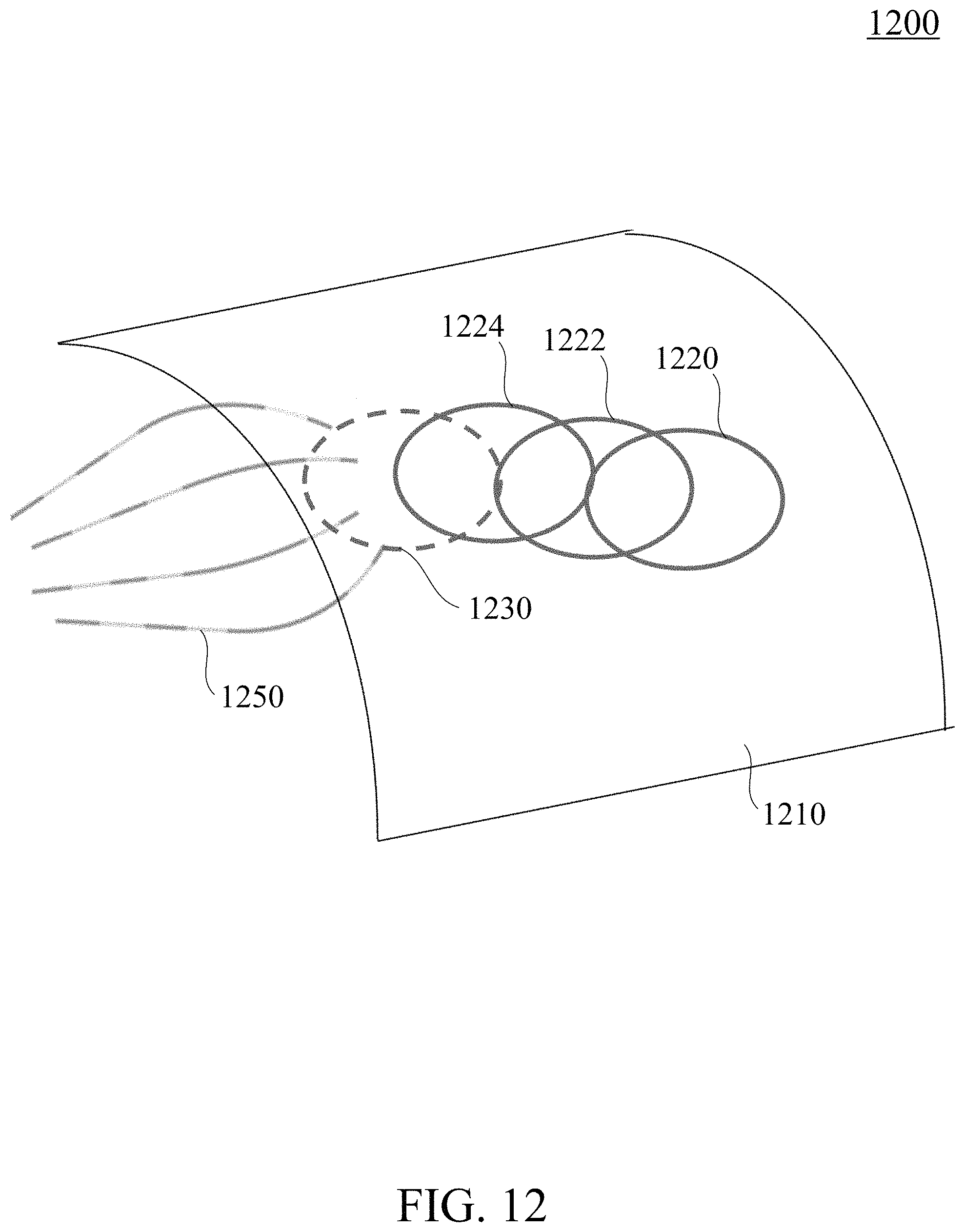
D00015

M00001

M00002

M00003

XML
uspto.report is an independent third-party trademark research tool that is not affiliated, endorsed, or sponsored by the United States Patent and Trademark Office (USPTO) or any other governmental organization. The information provided by uspto.report is based on publicly available data at the time of writing and is intended for informational purposes only.
While we strive to provide accurate and up-to-date information, we do not guarantee the accuracy, completeness, reliability, or suitability of the information displayed on this site. The use of this site is at your own risk. Any reliance you place on such information is therefore strictly at your own risk.
All official trademark data, including owner information, should be verified by visiting the official USPTO website at www.uspto.gov. This site is not intended to replace professional legal advice and should not be used as a substitute for consulting with a legal professional who is knowledgeable about trademark law.