Apparatus And Method For Intra-cardiac Mapping And Ablation
GELBART; Daniel ; et al.
U.S. patent application number 16/369528 was filed with the patent office on 2019-07-25 for apparatus and method for intra-cardiac mapping and ablation. The applicant listed for this patent is Kardium Inc.. Invention is credited to Daniel GELBART, Samuel Victor LICHTENSTEIN.
| Application Number | 20190223950 16/369528 |
| Document ID | / |
| Family ID | 48780484 |
| Filed Date | 2019-07-25 |


| United States Patent Application | 20190223950 |
| Kind Code | A1 |
| GELBART; Daniel ; et al. | July 25, 2019 |
APPARATUS AND METHOD FOR INTRA-CARDIAC MAPPING AND ABLATION
Abstract
An intra-cardiac mapping system is based on locating the ports through which blood flows in or out the heart chambers. For many procedures, such as ablation to cure atrial fibrillation, locating the pulmonary veins and the mitral valve accurately allows to perform a Maze procedure. The location of the ports and valves is based on using the convective cooling effect of the blood flow. The mapping can be performed by a catheter-deployed expandable net or a scanning catheter. The same net or catheter can also perform the ablation procedure.
| Inventors: | GELBART; Daniel; (Vancouver, CA) ; LICHTENSTEIN; Samuel Victor; (Vancouver, CA) | ||||||||||
| Applicant: |
|
||||||||||
|---|---|---|---|---|---|---|---|---|---|---|---|
| Family ID: | 48780484 | ||||||||||
| Appl. No.: | 16/369528 | ||||||||||
| Filed: | March 29, 2019 |
Related U.S. Patent Documents
| Application Number | Filing Date | Patent Number | ||
|---|---|---|---|---|
| 15697744 | Sep 7, 2017 | |||
| 16369528 | ||||
| 14804810 | Jul 21, 2015 | 9987083 | ||
| 15697744 | ||||
| 13785931 | Mar 5, 2013 | 9119633 | ||
| 14804810 | ||||
| 11475950 | Jun 28, 2006 | 8920411 | ||
| 13785931 | ||||
| Current U.S. Class: | 1/1 |
| Current CPC Class: | A61B 2018/0237 20130101; A61B 18/082 20130101; A61B 2018/00357 20130101; A61B 18/20 20130101; A61B 34/25 20160201; A61B 5/6858 20130101; A61B 2018/00642 20130101; A61B 5/028 20130101; A61B 5/02055 20130101; A61B 5/027 20130101; A61B 34/10 20160201; A61B 18/18 20130101; A61B 2018/00351 20130101; A61B 2018/00714 20130101; A61B 18/02 20130101; A61B 2018/00577 20130101; A61B 18/10 20130101; A61B 5/6853 20130101; A61B 5/743 20130101; A61B 90/37 20160201; A61B 2018/0016 20130101; A61B 2034/101 20160201; A61B 2018/0022 20130101; A61B 2018/00875 20130101; A61B 2018/00791 20130101; A61B 2018/0212 20130101; A61B 2018/00267 20130101; A61B 2018/124 20130101; A61B 2562/046 20130101; A61B 5/015 20130101; A61B 18/1492 20130101; A61B 2018/1407 20130101 |
| International Class: | A61B 18/14 20060101 A61B018/14; A61B 18/08 20060101 A61B018/08; A61B 5/028 20060101 A61B005/028; A61B 18/10 20060101 A61B018/10; A61B 5/00 20060101 A61B005/00; A61B 34/00 20060101 A61B034/00; A61B 34/10 20060101 A61B034/10; A61B 90/00 20060101 A61B090/00; A61B 5/027 20060101 A61B005/027; A61B 5/0205 20060101 A61B005/0205; A61B 5/01 20060101 A61B005/01 |
Claims
1. (canceled)
2. An ablation-pattern display system comprising: a control computer; and at least one display console connected to the control computer, the control computer configured to: cause the at least one display console to display a visual representation indicating each ablation element in a first ablation element set in an overlapping relationship with an opening in an intra-cardiac cavity, the visual representation indicating each ablation element in a second ablation element set in an overlapping relationship with tissue surrounding at least part of the opening in the intra-cardiac cavity, at least part of the visual representation derived at least in part from information provided to the control computer from a sensing element set positionable in the intra-cardiac cavity, and the ablation elements in the first and the second ablation element sets providing a plurality of ablation elements arrangeable in a spatial distribution in a state in which the plurality of ablation elements is deployed in the intra-cardiac cavity, each ablation element of the plurality of ablation elements selectively operable to cause tissue ablation; receive user-input indicating user-selected ablation elements of at least some of the ablation elements in the second ablation element set to define a user-selected tissue ablation pattern; and cause, prior to beginning ablation of the user-selected tissue ablation pattern, the at least one display console to display the visual representation as including a graphical representation of the user-selected tissue ablation pattern at least in response to the user-input, the graphical representation visually indicating a plurality of first graphical elements, the plurality of first graphical elements respectively corresponding to the user-selected ablation elements, wherein the visual representation comprises a plurality of second graphical elements, at least some of the plurality of first graphical elements surrounding at least some of the plurality of second graphical elements, the plurality of second graphical elements respectively corresponding to non-user-selected ablation elements, the plurality of second graphical elements depicted differently within the visual representation than the plurality of first graphical elements, and the plurality of first graphical elements and the plurality of second graphical elements collectively spatially arranged in the visual representation in correspondence with the spatial distribution.
3. The ablation-pattern display system of claim 2, wherein the visual representation visually indicates the plurality of first graphical elements and the plurality of second graphical elements in an arrangement comprising a plurality of rows and a plurality of columns, wherein each row of (a) at least two of the rows, each column of (b) at least two of the columns, or each row and column of both (a) and (b) respectively comprises graphical depictions of at least one graphical element of the plurality of first graphical elements and at least one graphical element of the plurality of second graphical elements.
4. The ablation-pattern display system of claim 2, wherein the visual representation visually indicates the plurality of first graphical elements and the plurality of second graphical elements in an arrangement comprising a plurality of rows and a plurality of columns, wherein each row of (a) at least two of the rows, each column of (b) at least two of the columns, or each row and column of both (a) and (b) respectively comprises graphical depictions of at least two graphical elements of the plurality of first graphical elements.
5. The ablation-pattern display system of claim 2, wherein the graphical representation of the user-selected tissue ablation pattern represents the user-selected tissue ablation pattern as comprising elongated segments along different ones of multiple axes.
6. The ablation-pattern display system of claim 5, wherein the plurality of first graphical elements are the elongated segments.
7. The ablation-pattern display system of claim 2, wherein the control computer is further configured to cause the at least one display console to display a grid comprising a plurality of rows and a plurality of columns, wherein the graphical representation of the user-selected tissue ablation pattern occurs in alignment with the rows and columns of the grid.
8. The ablation-pattern display system of claim 2, wherein each graphical element of the plurality of first graphical elements and each graphical element of the plurality of second graphical elements is an elongated segment.
9. The ablation-pattern display system of claim 2, wherein the plurality of ablation elements is formed as a mesh.
10. The ablation-pattern display system of claim 2, wherein the plurality of ablation elements is configured to assume different positions including a position suitable for percutaneous delivery to the intra-cardiac cavity and an expanded position in which the plurality of ablation elements is deployed in the intra-cardiac cavity.
11. The ablation-pattern display system of claim 2, wherein the plurality of first graphical elements, which respectively correspond to the user-selected ablation elements, are emphasized as compared to the plurality of second graphical elements, which respectively correspond to the non-user-selected ablation elements.
12. The ablation-pattern display system of claim 2, wherein each ablation element of the plurality of ablation elements is configured to ablate tissue using RF ablation, laser ablation, microwave ablation, or cryogenic ablation.
13. The ablation-pattern display system of claim 2, wherein each sensing element in the sensing element set is configured to sense blood flow.
14. The ablation-pattern display system of claim 13, wherein the control computer is configured to cause each ablation element of at least some ablation elements of the plurality of ablation elements to be switchable between (a) a mapping mode in which the ablation element is operable to provide sensed blood flow information, and (b) an ablation mode in which the ablation element is operable to ablate tissue.
15. The ablation-pattern display system of claim 2, wherein each sensing element in the sensing element set is configured to sense temperature.
16. The ablation-pattern display system of claim 2, wherein the sensing element set comprises a plurality of sensing elements arranged in an array.
17. The ablation-pattern display system of claim 2, wherein the sensing element set is configured to indicate a positioning of a portion of a catheter in the intra-cardiac cavity, the catheter comprising at least the plurality of ablation elements.
18. The ablation-pattern display system of claim 17, wherein the catheter comprises the sensing element set.
19. The ablation-pattern display system of claim 2, wherein the sensing element set is configured to indicate a positioning of each ablation element in the second ablation element set in the overlapping relationship with the tissue surrounding the at least part of the opening in the intra-cardiac cavity.
20. The ablation-pattern display system of claim 19, wherein the sensing element set is configured to indicate a positioning of each ablation element in the first ablation element set in the overlapping relationship with the opening in the intra-cardiac cavity.
21. The ablation-pattern display system of claim 20, wherein a catheter comprises the plurality of ablation elements and the sensing element set.
22. The ablation-pattern display system of claim 2, wherein the plurality of ablation elements is connected to the control computer, and wherein the control computer is configured to operate the user-selected ablation elements of the plurality of ablation elements to cause ablation of the user-selected tissue ablation pattern in tissue of the intra-cardiac cavity.
23. An ablation-pattern display method executed by a control computer, the method comprising: causing at least one display console connected to the control computer to display a visual representation indicating each ablation element in a first ablation element set in an overlapping relationship with an opening in an intra-cardiac cavity, the visual representation indicating each ablation element in a second ablation element set in an overlapping relationship with tissue surrounding at least part of the opening in the intra-cardiac cavity, at least part of the visual representation derived at least in part from information provided to the control computer from a sensing element set positionable in the intra-cardiac cavity, and the ablation elements in the first and the second ablation element sets providing a plurality of ablation elements arrangeable in a spatial distribution in a state in which the plurality of ablation elements is deployed in the intra-cardiac cavity, each ablation element of the plurality of ablation elements selectively operable to cause tissue ablation; receiving user-input indicating user-selected ablation elements of at least some of the ablation elements in the second ablation element set to define a user-selected tissue ablation pattern; and causing, prior to beginning ablation of the user-selected tissue ablation pattern, the at least one display console to display the visual representation as including a graphical representation of the user-selected tissue ablation pattern at least in response to the user-input, the graphical representation visually indicating a plurality of first graphical elements, the plurality of first graphical elements respectively corresponding to the user-selected ablation elements, wherein the visual representation comprises a plurality of second graphical elements, at least some of the plurality of first graphical elements surrounding at least some of the plurality of second graphical elements, the plurality of second graphical elements respectively corresponding to non-user-selected ablation elements, the plurality of second graphical elements depicted differently within the visual representation than the plurality of first graphical elements, and the plurality of first graphical elements and the plurality of second graphical elements collectively spatially arranged in the visual representation in correspondence with the spatial distribution.
Description
CROSS-REFERENCE TO RELATED APPLICATIONS
[0001] This application is a continuation of prior U.S. patent application Ser. No. 15/697,744, filed Sep. 7, 2017, which is a continuation of prior U.S. patent application Ser. No. 14/804,810, filed Jul. 21, 2015, now U.S. Pat. No. 9,987,083 issued on Jun. 5, 2018, which is a continuation of prior U.S. patent application Ser. No. 13/785,931, filed Mar. 5, 2013, now U.S. Pat. No. 9,119,633, issued on Sep. 1, 2015, which is a continuation-in-part of prior U.S. patent application Ser. No. 11/475,950, filed Jun. 28, 2006, now U.S. Pat. No. 8,920,411, issued on Dec. 30, 2014, the entire disclosure of each of these applications is hereby incorporated herein by reference.
TECHNICAL FIELD
[0002] This disclosure generally relates to minimally invasive heart surgery, also known as percutaneous cardiac surgery and particularly relates to percutaneous mapping and ablation.
BACKGROUND
[0003] Atrial fibrillation is a well known disorder in which spurious electrical signals cause an irregular heart beat. The disorder has a well known cure known as the Maze procedure, in which a border is ablated around the sources of the spurious signals, typically in the left atrium but sometimes in the right atrium. The procedure is very commonly performed under direct vision, but difficult to perform percutaneously via a catheter because of the associated risk. Any error in navigation inside the heart can cause fatal damage. The key to a percutaneous procedure is mapping of the inside of the right and left atrium. Access to the right atrium is simple via the superior vena cava; the left atrium can be reached i) by perforating the transatrial septum, ii) via the aorta and the left ventricle or iii) via the pulmonary veins.
[0004] Prior approaches to map the inside of the atrium relied on electrical activity picked up from the atrium wall. These approaches require intimate electrical contact, not always possible because of scar tissue and deposits. These approaches may fail to accurately map the edges of the openings where the veins enter the atrium; information that is useful for correct placement of the ablation pattern. Other mapping methods, such as using an array of ultrasonic transducers, are not practical since such arrays typically will not fit through a catheter of a reasonable size (8-10 mm diameter). A superior mapping apparatus and method, that enables safe execution of the Maze and other intra-cardiac procedures is desirable.
[0005] A good survey article on the subject is: "Ablation of Atrial Fibrillation: Energy Sources and Navigation Tools: A survey" by Ruediger Becker and Wolfgang Schoels (J. of Electrocardiology, Vol 37, 2004, pp 55-61). The article includes an extensive bibliography.
SUMMARY
[0006] Embodiments of an intra-cardiac mapping system are based on locating openings or ports and values through which blood flows in or out of the heart chambers. For many procedures, such as ablation to cure atrial fibrillation, accurately locating the pulmonary veins and the mitral valve allows performance of a Maze procedure. The openings, ports and valves may be located based on the convective cooling effect of the blood flow. The mapping can be performed by a catheter-deployed expandable net or a scanning catheter. The same net or catheter can also perform the ablation procedure.
[0007] In one embodiment, a method for intra-cardiac mapping comprises: introducing a plurality of flow sensors into an intra-cardiac cavity: locating points in a wall forming said cavity based on sensing blood flow; and mapping said walls of said cavity based on said points. The method for intra-cardiac mapping may include said blood flow being sensed by its convective cooling effect on a heated sensor. The method for intra-cardiac mapping may include said sensing being done by a steerable linear array. The method for intra-cardiac mapping may include said mapping being used for treating atrial fibrillation by RF ablation. The method for intra-cardiac mapping may include being used for treating atrial fibrillation by microwave ablation. The method for intra-cardiac mapping may include said mapping being used for treating atrial fibrillation by cryogenic ablation. The method for intra-cardiac mapping may include said mapping being used for treating atrial fibrillation by laser ablation. The method for intra-cardiac mapping may include said blood flow being sensed by the resistance change of a heated resistive wire.
[0008] In another embodiment, a method for intra-cardiac mapping comprises: introducing an expandable sensing mesh into said cavity via a catheter; using said mesh to locate openings in walls forming said cavity based on the convective heat transfer of blood flowing through said holes; and mapping inside of said cavity based on location of said openings. The method for intra-cardiac mapping may include said blood flow being sensed by its convective cooling effect on a heated sensor. The method for intra-cardiac mapping may include said sensing being done by a steerable linear array. The method for intra-cardiac mapping may include said mapping being used for treating atrial fibrillation by RF ablation. The method for intra-cardiac mapping may include said mapping being used for treating atrial fibrillation by microwave ablation. The method for intra-cardiac mapping may include said mapping being used for treating atrial fibrillation by cryogenic ablation. The method for intra-cardiac mapping may include said mapping being used for treating atrial fibrillation by laser ablation. The method for intra-cardiac mapping may include said blood flow being sensed by the resistance change of a heated resistive wire. The method for intra-cardiac mapping may include said mesh comprising small coils of nickel wire wound on a mesh of a flexible insulator. The method for intra-cardiac mapping may include an electronic switch used to minimize the number of electrical wires passing through said catheter.
[0009] In yet another embodiment, a method for treating atrial fibrillation comprises: introducing at least one flow sensor into an intra-cardiac cavity; locating points in a wall forming said cavity based on sensing blood flow; mapping walls of said cavity based on said points; and ablating a pattern into walls of said cavity based on said mapping. The method for treating atrial fibrillation may include said blood flow being sensed by its convective cooling effect on a heated sensor. The method for treating atrial fibrillation may include said sensing being done by a steerable linear array. The method for treating atrial fibrillation may include said mapping being used for treating atrial fibrillation by RF ablation. The method for treating atrial fibrillation may include said mapping being used for treating atrial fibrillation by microwave ablation. The method for treating atrial fibrillation may include said mapping being used for treating atrial fibrillation by cryogenic ablation. The method for treating atrial fibrillation may include said mapping being used for treating atrial fibrillation by laser ablation. The method for treating atrial fibrillation may include said blood flow being sensed by the resistance change of a heated resistive wire. The method for treating atrial fibrillation may include said flow sensors also acting as electrodes for said ablation. The method for treating atrial fibrillation may include said flow sensor being based on temperature sensing and a same sensor being used to monitor temperature during said ablation. The method for treating atrial fibrillation may include said ablation being unipolar. The method for treating atrial fibrillation may include said ablation being bipolar. The method for treating atrial fibrillation may include said ablated pattern being a Maze procedure.
BRIEF DESCRIPTION OF THE DRAWINGS
[0010] In the drawings, identical reference numbers identify similar elements or acts. It is to be understood that the attached drawings are for purposes of illustrating the concepts of the invention and may not be to scale. For example, the sizes, relative positions, shapes, and angles of or associated with elements in the drawings are not necessarily drawn to scale, and some elements may be arbitrarily enlarged and positioned to improve drawing legibility. Further, the particular shapes of the elements as drawn may differ from their actual shapes and, in this regard, may be selected instead of the respective actual shapes for ease of recognition in the drawings.
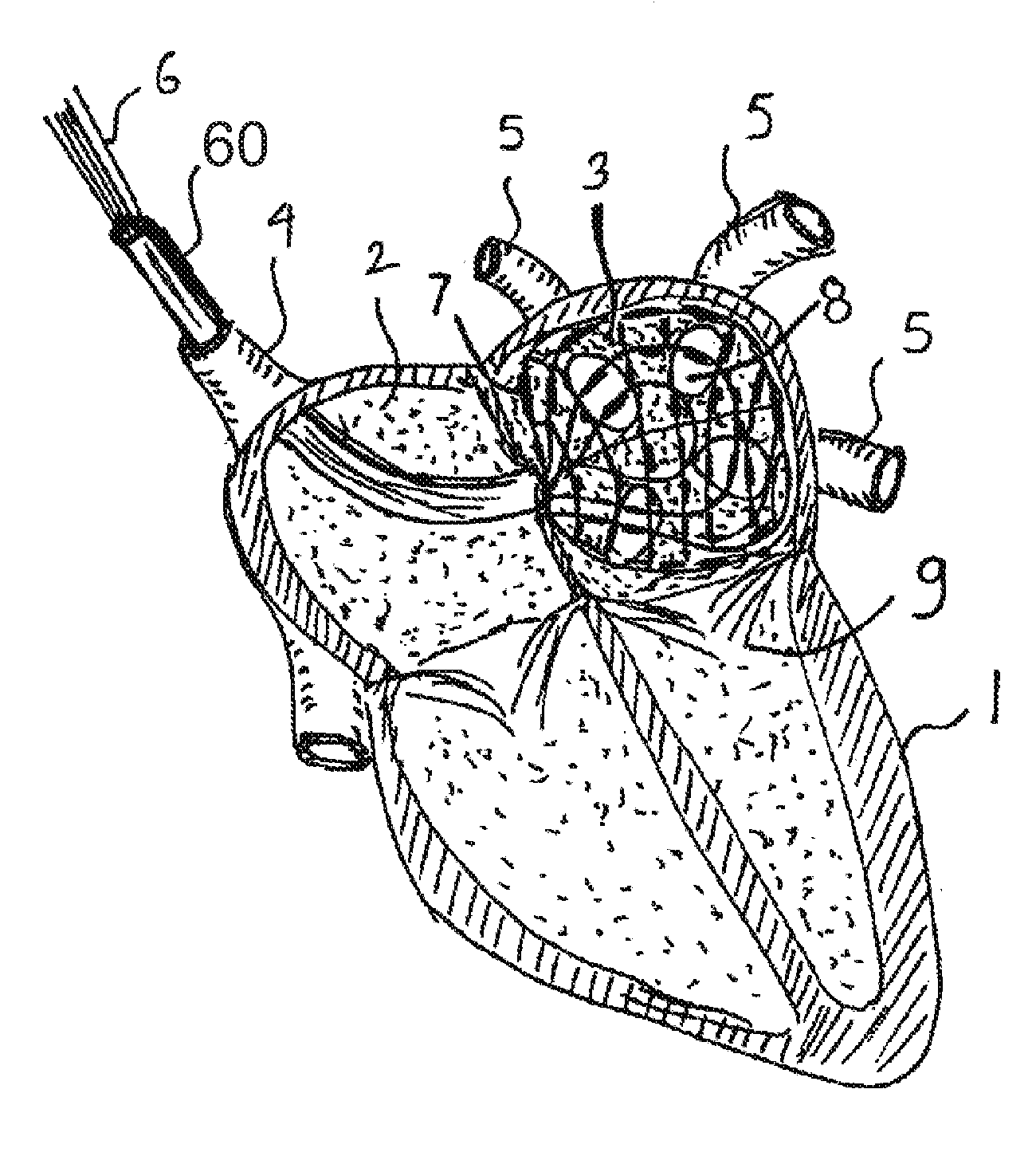
[0011] FIG. 1 is a cross sectional view of the heart showing the mapping mesh deployed in the left atrium.
[0012] FIG. 2 is a cross sectional view of the sensing device.
[0013] FIGS. 3A and 3B are isometric views of the mesh in both folded and expanded position.
[0014] FIG. 4 is an isometric enlarged view of a portion of the mesh.
[0015] FIG. 5 is an electrical schematic of a mapping and ablation system.
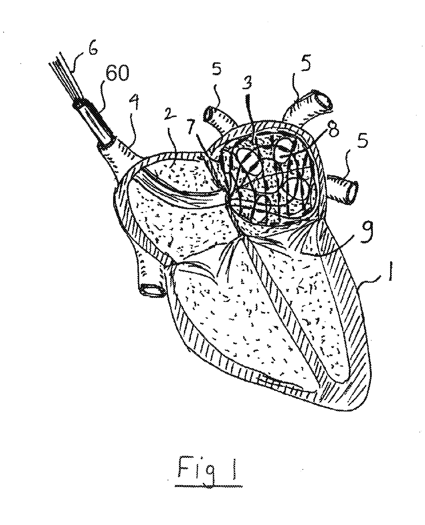
[0016] FIG. 6 is an electrical schematic of a simplified mapping system.
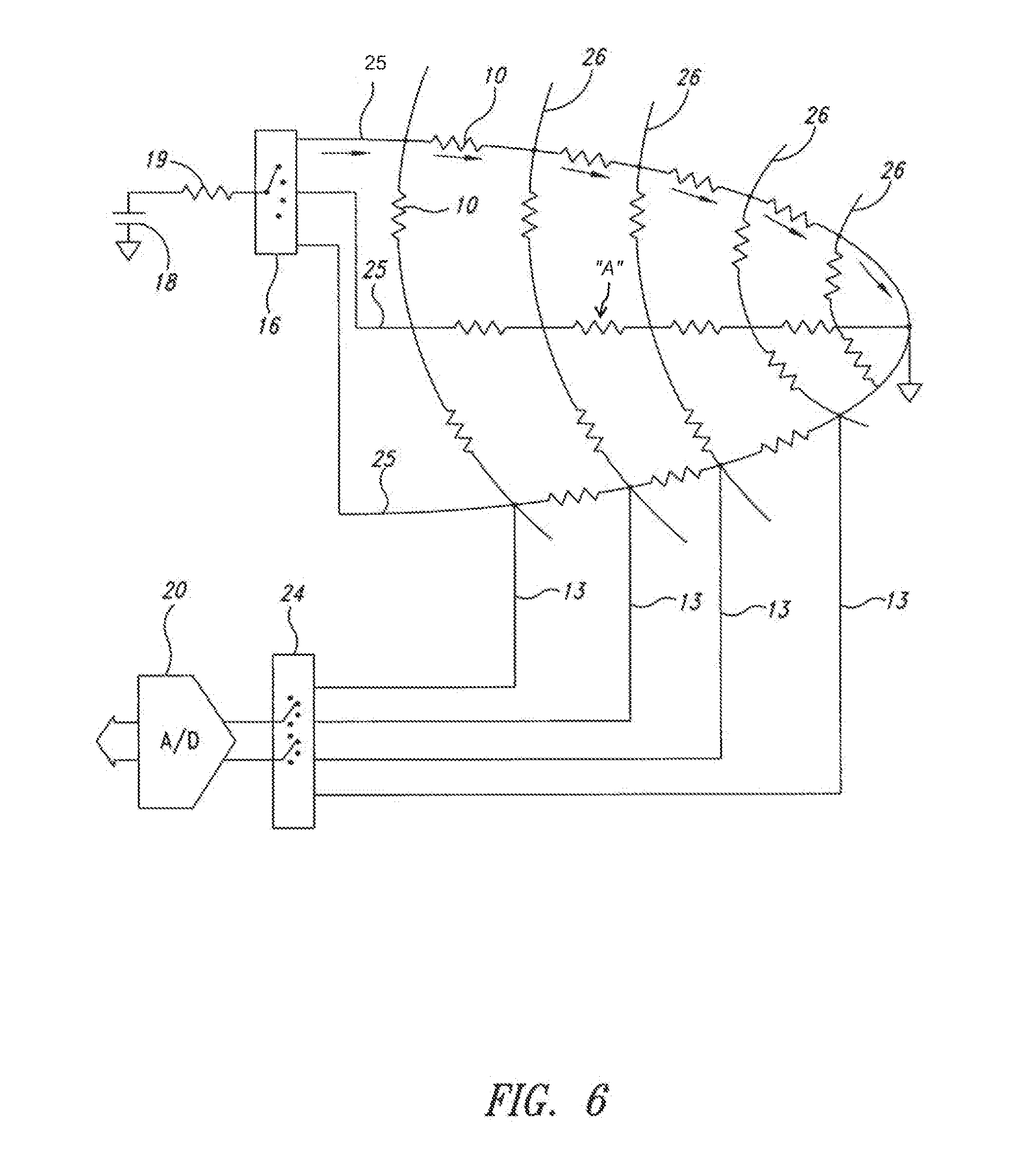
[0017] FIG. 7 is a schematic view of the display console of the system.
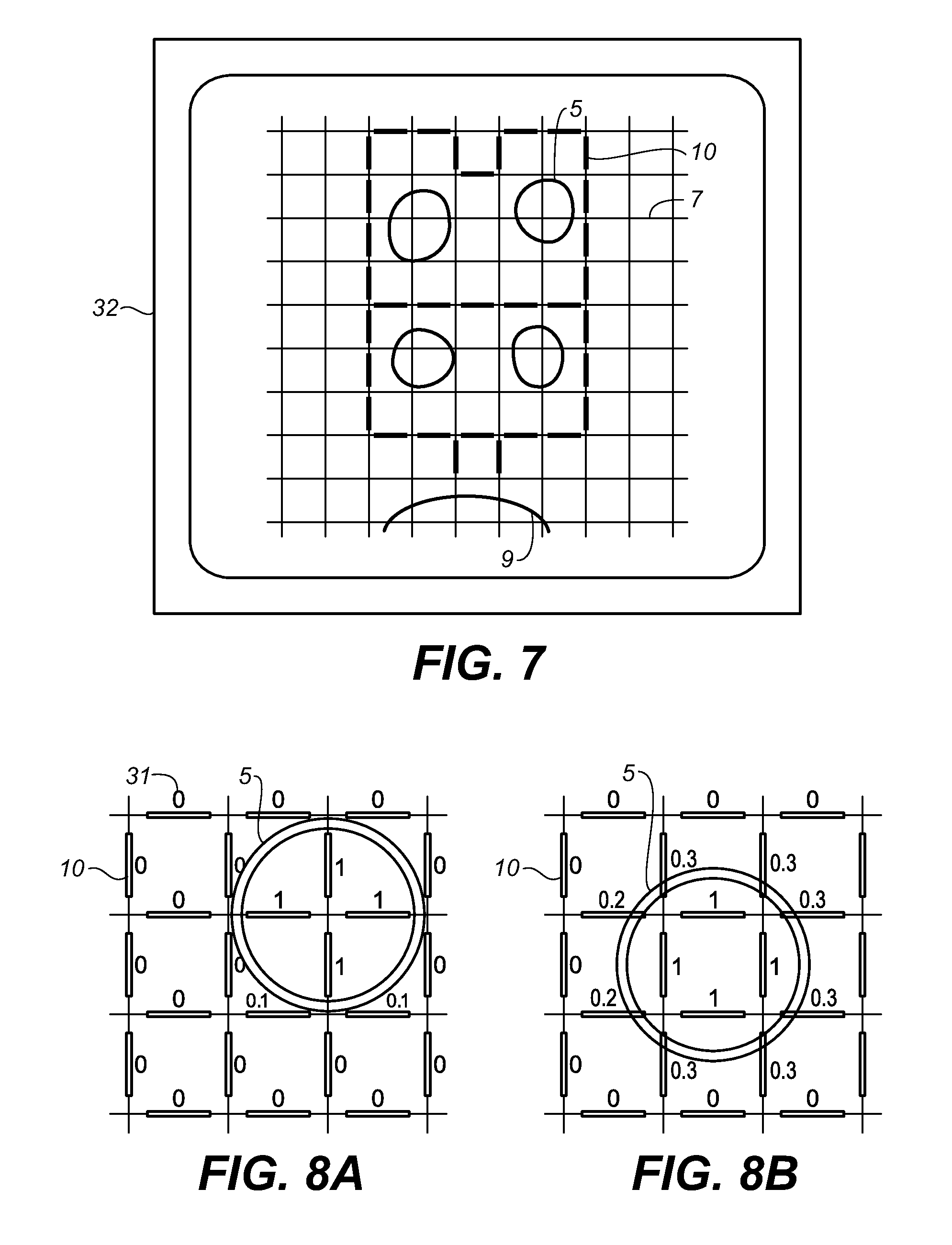
[0018] FIGS. 8A and 8B are graphical views of a mapping that illustrate an interpolation principle.
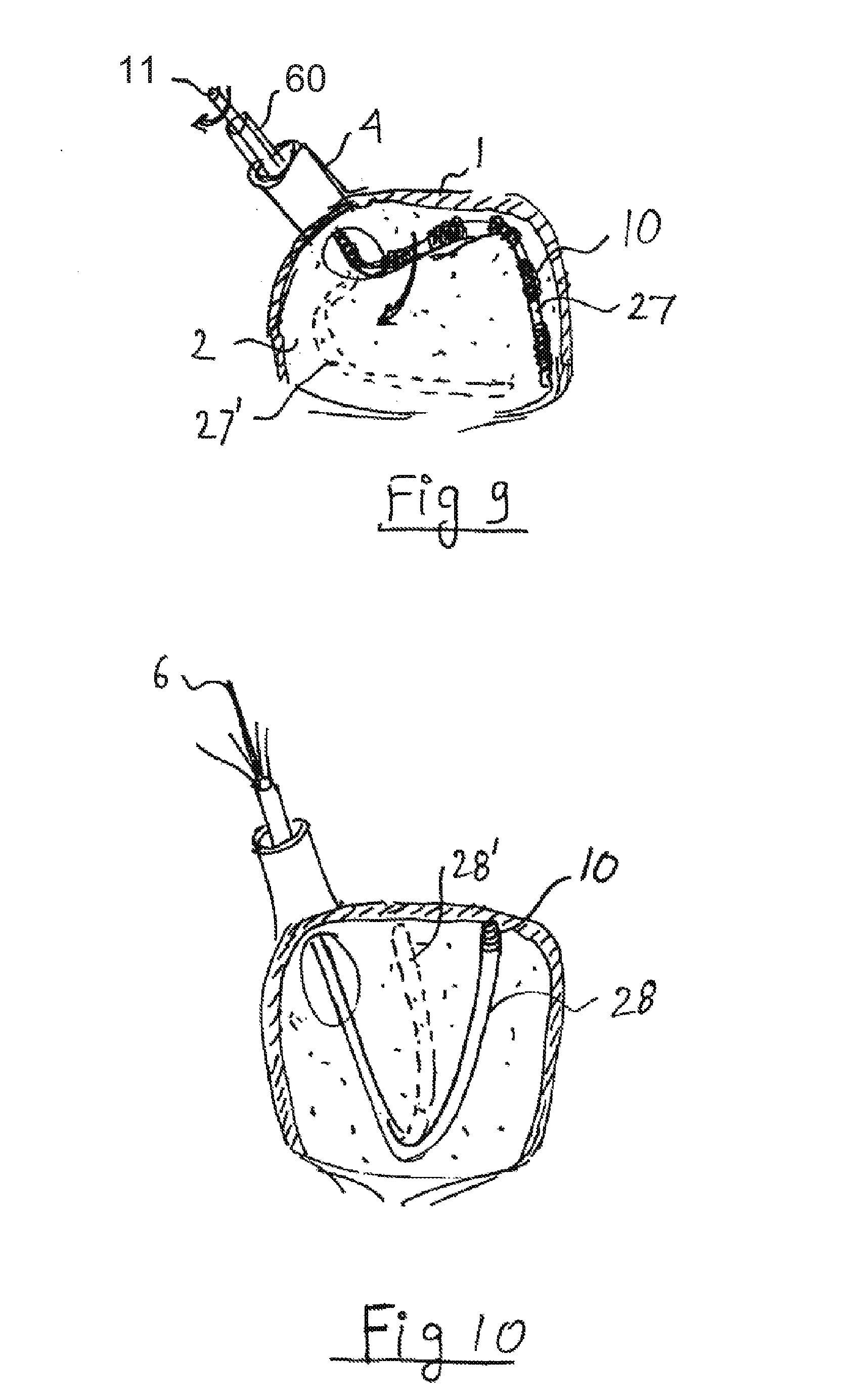
[0019] FIG. 9 is a cross sectional view of an alternate embodiment, using mechanical or manual scanning in one axis.
[0020] FIG. 10 is a cross sectional view of an alternate embodiment, using mechanical scanning in two dimensions.
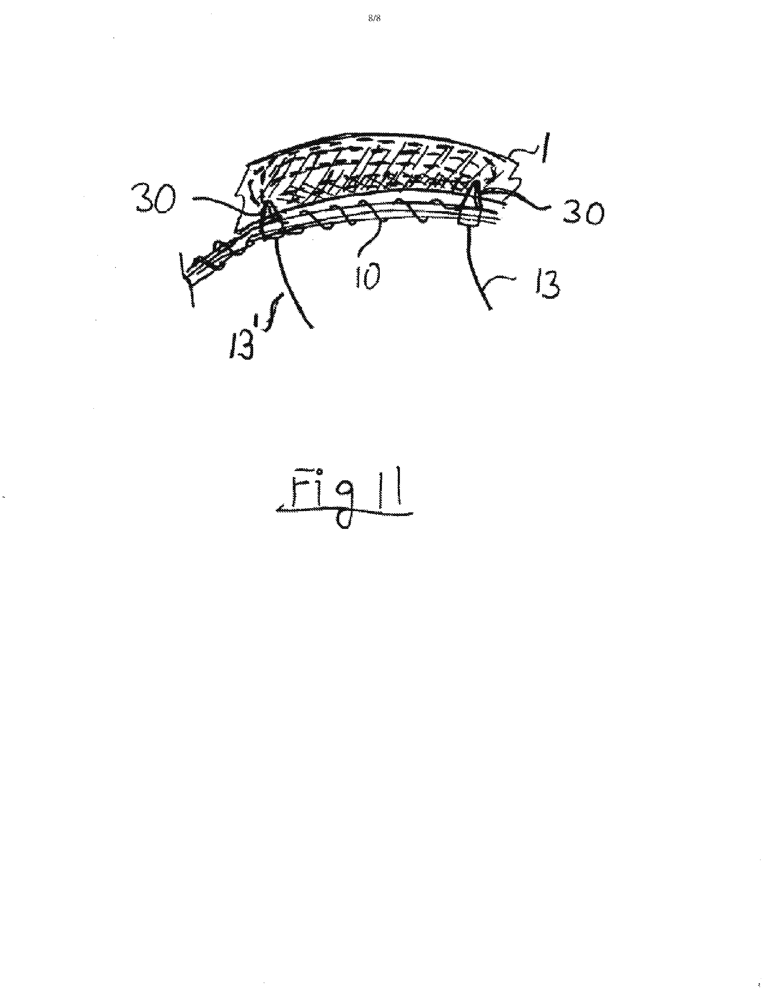
[0021] FIG. 11 shows the use of the invention for bipolar ablation.
DETAILED DESCRIPTION
[0022] In the following description, certain specific details are set forth in order to provide a thorough understanding of various disclosed embodiments. However, one skilled in the relevant art will recognize that embodiments may be practiced without one or more of these specific details, or with other methods, components, materials, etc. In other instances, well-known structures associated with apparatuses and methods for intra-cardiac mapping and ablation have not been shown or described in detail to avoid unnecessarily obscuring descriptions of the embodiments.
[0023] Unless the context requires otherwise, throughout the specification and claims which follow, the word "comprise" and variations thereof, such as, "comprises" and "comprising" are to be construed in an open, inclusive sense, that is as "including, but not limited to."
[0024] Reference throughout this specification to "one embodiment" or "an embodiment" means that a particular feature, structure or characteristic described in connection with the embodiment is included in at least one embodiment. Thus, the appearances of the phrases "in one embodiment" or "in an embodiment" in various places throughout this specification are not necessarily all referring to the same embodiment. Furthermore, the particular features, structures, or characteristics may be combined in any suitable manner in one or more embodiments.
[0025] As used in this specification and the appended claims, the singular forms "a," "an," and "the" include plural referents unless the content clearly dictates otherwise. It should also be noted that the term "or" is generally employed in its non-exclusive sense including "and/or" unless the content clearly dictates otherwise.
[0026] The headings and Abstract of the Disclosure provided herein are for convenience only and do not interpret the scope or meaning of the embodiments.
[0027] FIG. 1 shows a sensing and ablation mesh 7 inserted into a left atrium 3 of a heart 1 according to one illustrated embodiment.
[0028] By way of example, the mesh 7 may be delivered via a catheter 60 inserted via a superior vena cava 4 and penetrating a transatrial septum from a right atrium 2 of the heart 1. The mesh 7 is communicatively coupled to the rest of the system, for example, by electrical wires 6.
[0029] Before any ablation takes place, the inside of the left atrium 3 is mapped in order to locate the openings or ports 8 leading to the pulmonary veins 5, as well as the mitral valve 9. A typical Maze procedure ablates a "fence" around openings or ports 8 to stop propagation of spurious electrical signals which cause the heart 1 to contract at the wrong times.
[0030] The mapping may locate some or all of the openings or ports 8 through which blood flows in and out of the left atrium 3, as the Maze procedure is mainly concerned with the location of these openings or ports 8. By the way of example, in the left atrium 3, the four openings or ports 8 leading to the pulmonary veins 5 as well as the mitral valve 9 may be located. The location of these openings or ports 8 may be based on the fact that the convective cooling effect of the blood is significant, and a slightly heated mesh 7 pressed against the walls of the left and/or right atrium 3, 2 will be cooler at the areas which are spanning the openings or ports 8 carrying blood.
[0031] FIG. 2 shows the ablation mesh 7 covered by miniature heating and/or temperature sensing elements 10a-10c flow (collectively 10, only three illustrated in the figure). Each one of these elements 10a-10c comprises a few turns of a resistive wire, for example nickel wire, wound on an electrically insulated mesh. A low current is passed through each element 10, raising a temperature of the element 10 by about 1 degree C. above normal blood temperature. A first element 10b, which lies across an opening or port 8 of one of the pulmonary veins 5, will be cooled by blood flow. The other elements are against a wall 3 and hence do not lie across any of the openings or ports 8.
[0032] By identifying the relatively cooler elements 10a, 10c on the mesh 7, the location of the openings or ports 8 may be found.
[0033] This method does not require intimate contact with the wall 3, as the cooling effect is significant even a few millimeters away from the opening.
[0034] The same elements 10 can be used as ablation electrodes during an ablation stage. It was found that the power required to raise the temperature of the mesh 7 by a small but easily detectable amount is very small, on the order of 10-50 mW per element 10. If the elements 10 are made of a material that has a significant change in resistance with temperature, the temperature drop can be sensed by measuring a voltage across the element 10 when driven by a constant current. A good choice for element material is nickel wire, which is inert, highly resistive and has a significant temperature coefficient of resistance (about 0.6% per deg C.). Since the resistance of the elements 10 is low (typically 0.1-1 ohm), the electrical noise is very low and temperature changes as low as 0.1 deg can be easily detected. For even higher detection sensitivity, the voltage waveform can be sampled in sychronization with the heart rate or the average voltage removed and only the change amplified. Such methods are referred to as "AC coupling". A further refinement to reduce the electrical noise is to pass the signal through a digital band pass filter having a center frequency tracking the heart rate. To avoid any potential tissue damage, the temperature of the elements 10 of the mesh 7 is only slightly above the blood temperature, typically 0.1-3 degrees C. above blood temperature.
[0035] FIG. 3A shows the mesh 7 in a compressed configuration "A" and FIG. 3B shows the mesh 7 in an expanded configuration "B". Since the mesh 7 has to fit into a catheter 60, the mesh 7 should be very flexible. Besides elements 10 discussed earlier, there is also a large number of leads 13 coming out of the mesh 7. Leads 13 can be loose, as shown in FIG. 3B, or may be bonded to the mesh 7. To avoid feeding a large number of wires all the way to an operating console, an electronic selector switch may be employed, which may, for example, be mounted in the catheter 60. This reduces the number of electrical wires from over 100 to about 10. The mesh 7 can be self-expanding (elastic) or balloon-expandable. Self expanding allows normal blood flow during the procedure. For balloon expandable devices, the expansion balloon should be removed before the mapping, to avoid blocking the flow of blood.
[0036] FIG. 4 shows the mesh 7 in more detail. Insulated longitudinal (i.e., parallel to catheter) wires 25 are crossed by cross wires 26. Each section of the mesh 7 is covered by a few turns of thin (0.05-0.2 mm) nickel wire 10 having leads 13. The leads 13 can be regular thin copper wire. The longitudinal wires 25 can be stiffer than the cross wires 26, therefore can be made self-expanding by incorporating a core 14 made of coiled flexible metal wire such as Nitinol. A metallic core may interfere with the ablation process at higher frequencies and can be replaced by simply making the longitudinal wires 25 of a polymeric material thicker than the cross wires 26. The cross wires 26, which may form rings around wires 25, should be very flexible to compress into the catheter 60. The cross wires 26 could incorporate a very thin wire or coiled up wire. Use of a flexible mesh 7 not only allows percutaneous delivery, but also permits the mesh 7 to follow the atrial volume change each heartbeat. The mesh 7 should stay in contact with or close to the atrial wall during the cardiac cycle, otherwise the measurement and the ablation may only be performed during parts of the cardiac cycle. The diameter of the longitudinal wires 25 and cross wires 26 are typically 0.2-1 mm. The mesh 7 may include about 10-20 longitudinal wires 25 and about 10-20 cross wires 26. The insulation can be any polymeric material such as thin enamel or polymer coating. Practically any polymer can be used, as the maximum temperature it will be subject to, including during the ablation phase, is around 100 degrees C.
[0037] FIG. 5 shows an electrical system, according to one illustrated embodiment. The elements 10 may be resistive heaters wound on the mesh 7. Each of the elements 10 is connected by electronic element switches 15 (typically FET or MOS-FET type) to a single pair of wires leading out of the body to a mode selection switch 17. Element switches 15 are selected by de-multiplexer or selector 16. The de-multiplexer or selector 16 is controlled by a small number of wires or even a single wire if data is sent in serial form, by a multiplexer 22. Element switches 15 and de-multiplexer or selector 16 may be built into the catheter 60, which may, for example, be located near the point of deployment of the mesh 7. The element switches 15 have to carry significant power during the ablation phase.
[0038] The mode selection 17 selects between a mapping mode (position shown in the drawing) and an ablation mode (second position of switch). In the mapping mode, a current is created by a voltage source 18 and resistor 19 (e.g., forming a constant current source) and routed into a selected element 10 by the element switches 15. For each measurement, the two element switches 15 that are connected to the scanned element 10 are in an enabled state (ON), the rest of the element switches being in a disabled state (OFF). The voltage drop across an element 10 is measured by an analog to digital (A/D) converter 20 and fed to a control computer 23. For greater accuracy, four terminal sensing can be employed. In a preferred embodiment, the detection is AC coupled, therefore the DC voltage drops along the wires are of no consequence, and no four-terminal sensing is needed. For AC coupling, the control computer 23 may include a 0.5 Hz low pass filter, which may be implemented in software. The slight disadvantage of the AC coupled method approach is speed, as the low signal frequency (e.g., about 1 Hz), requires a few seconds per measurement. Other temperature sensors and/or approaches, such as thermistors or thermocouples, can be used in conjunction with the elements 10. Mapping is achieved by turning on all of the elements 10 (e.g., sequentially) and measuring the temperature of each. A map may be formed in the control computer 23 and the lower temperature spots on the mesh correspond to the openings or ports 8 leading to the veins or valves.
[0039] When the mode selection switch 17 is in the ablation mode, a generator 21 (e.g., Radio Frequency (RF)) is connected (e.g., sequentially) to selected elements 10 by the control computer 23 addressing the multiplexer 22 which controls the element switches 15 via the de-multiplex selector 16. The complete operation, including scanning and ablation, can be completed in less than 5 minutes. The configuration illustrated in FIG. 5 implies unipolar ablation; however bipolar ablation can be used as well and is discussed below. Clearly other sources of ablation can be used besides RF. Frequencies from DC to microwaves can be used, as well as delivery of laser power via optical fibers or cryogenics via thin tubes. For laser ablation element switches 15 are optical switches, while for cryogenic ablation the element switches 15 are valves, and in some embodiments may take the form of heated elements such as resistive wires.
[0040] During ablation it is desirable to monitor the temperature of the mode selection switch 17 to the mapping position several times during the ablation procedure. The measured temperatures can be displayed on a display 32 (FIG. 7). RF ablation is typically performed at frequencies of 100 KHz-1 MHz and power levels which depend on the size of the elements 10, but can be as high as 100 W. Various RF ablation techniques and equipment are well known in the art.
[0041] FIG. 6 shows an embodiment in which the mapping system is separate from the ablation system. In this system, the mesh 7 has very few connecting wires. As illustrated, each longitudinal wire 25 has a single output wire and each cross wire 26 has a single output wire 13. For a 10.times.10 mesh 7 with 100 nodes, only twenty-one wires are needed (ten plus ten plus ground wire), instead of two hundred wires. This allows all wires to be brought directly out of the catheter 60. This also allows placement of selector switches 16 and 24 together with the control system. For example, if the element marked as "A" is selected; a current is selected to run through the longitudinal wire 25 which includes element A. The voltage drop is sensed by the two circumferential wires 13 that connect directly to A. Since no current flows in the other elements at the time of measurement, the voltage drop is only caused by element A. It is sensed by A/D converter 20 via double pole selector 24.
[0042] After a map is established, it is displayed on a display screen 32 as shown in FIG. 7. The surgeon can select which elements 10 will cause tissue ablation in the atrium. The pattern formed is along the line of the standard Maze procedure. The location of the pulmonary veins 5 and the mitral valve 9 is inferred from the temperature date and drawn on the display screen.
[0043] FIGS. 8A and 8B demonstrate the principle of accurate location of the veins and valves even if the grid is relatively coarse. The exact location can be interpolated based on the fact that when only part of the element 10 is exposed to the blood flow. By the way of example, if the temperature of the mesh 7 is 1 degree C. above blood temperature and equals the blood temperature under normal blood flow (this was experimentally verified), the temperatures of a group of elements 10 will be as shown in FIG. 8A when aligned with the opening or port 8 of vein 5. The number near each element 10 is the temperature drop. When moved, some of the elements 10 will only be partially positioned in the flow path under vein 5, as shown by FIG. 8B. The temperatures of those elements 10 will be between 0 and 1 degree above blood temperature. The exact temperature drop between 0 to 1 corresponds with the exact shift. This allows accurate determination of the location and size of each opening or port 8, data used by the control computer 23 to draw the map shown in FIG. 7. A grid spacing of 10 mm allows about 1 mm accuracy.
[0044] An alternative to a full mesh is a partial mesh, or even a single sensor, that is mechanically scanned across the area to be mapped. FIG. 9 shows a linear sensor array 27 pushed into the atrium 2 via vein 4 by the catheter 60. The linear sensor array 27 has a linear array of elements 10 similar to those used in the full mesh 7. After a linear mapping is performed the linear sensor array 27 is rotated (as shown by broken line 27') a small amount (10-20 degrees) by stem 11 (similar to electrical wires 6) and a new scan is performed. The same procedures previously described may be used for ablation.
[0045] FIG. 10 shows the use of a single steerable catheter 28 as a mapping and ablation tool. Steerable catheters are controlled remotely by mechanical, magnetic, hydraulic or other means. A steerable catheter 28 can be used to scan the inside of the atrium 3 by bending, as shown in broken line 28'. The location is monitored by external or internal sensors. A position of a tip of the steerable catheter 28 can also be monitored by fluoroscopy. The catheter tip contains a heating and/or ablation element 10. Steerable catheters 28 may advantageously carry a wide range of ablation systems, since only one connection and one point is needed.
[0046] A full mesh trades a higher complexity for better speed and accuracy when compared to linear arrays or single point scanning.
[0047] The previous examples were of unipolar ablation, with the ablation current returning to ground via the patient's body. The disclosed system can also be used for bipolar ablation as shown in FIG. 11. In unipolar ablation the same voltage is connected to both leads 13 and 13' of an element 10. In bipolar abalation the voltage is connected to lead 13 while the other end, 13', is grounded. It is important that the element 10 will be of sufficient resistance to cause most of the ablation current to flow through heart tissue 1. Electrodes 30 make contact with tissue 1 while the wire used in the element 10 is covered by an insulator. The advantage of bipolar ablation is better control of ablation depth. Typical ablation temperatures are 60-80 degrees C. At a higher temperature the tissue 1 becomes less conductive, forcing the ablation current to seek a new path. This promotes full ablation of the tissue 1. The element 10 can also be designed to assist ablation by creating heat when ablation voltage is applied across it.
[0048] One possible advantage of at least some of the presently disclosed embodiments over electrical potential mapping methods is that the presently disclosed embodiments do not require perfect contact between the mesh 7 and the tissue 1. The presently disclosed embodiments may also advantageously be less sensitive to the surface properties of the tissue, such as scar tissue or plaque.
[0049] If the mesh is separated from the tissue by a thin layer of blood, both the temperature sensing and the ablation functions of the presently disclosed embodiments will still function properly.
[0050] The word "element" in this disclosure has to be interpreted in a broad sense as any element capable of sensing blood flow. Clearly the elements do not need to be heaters, as cooling elements will work equally well. If a material is injected into the blood flow, any sensor capable of detecting this material can be used to detect blood flow. By the way of example, if the blood is cooled or warmed slightly before returning to the heart only temperatures sensors are needed. Since temperature differences as low as 0.1 degree C. can be detected reliably, it is fairly simple to heat or cool the blood slightly before it returns to the heart (even by a simple external pad).
[0051] The above description of illustrated embodiments, including what is described in the Abstract, is not intended to be exhaustive or to limit the embodiments to the precise forms disclosed. Although specific embodiments of and examples are described herein for illustrative purposes, various equivalent modifications can be made without departing from the spirit and scope of the disclosure, as will be recognized by those skilled in the relevant art.
[0052] The various embodiments described above can be combined to provide further embodiments. All of the U.S. patents. U.S. patent application publications, U.S. patent applications, foreign patents, foreign patent applications and non-patent publications referred to in this specification and/or listed in the Application Data Sheet are incorporated herein by reference, in their entirety. Aspects of the embodiments can be modified, if necessary, to employ systems, circuits and concepts of the various patents, applications and publications to provide yet further embodiments.
[0053] These and other changes can be made to the embodiments in light of the above-detailed description. In general. in the following claims, the terms used should not be construed to limit the claims to the specific embodiments disclosed in the specification and the claims, but should be construed to include all possible embodiments along with the full scope of equivalents to which such claims are entitled. Accordingly, the claims are not limited by the disclosure.
* * * * *
D00000
D00001
D00002
D00003
D00004
D00005
D00006
D00007
D00008
XML
uspto.report is an independent third-party trademark research tool that is not affiliated, endorsed, or sponsored by the United States Patent and Trademark Office (USPTO) or any other governmental organization. The information provided by uspto.report is based on publicly available data at the time of writing and is intended for informational purposes only.
While we strive to provide accurate and up-to-date information, we do not guarantee the accuracy, completeness, reliability, or suitability of the information displayed on this site. The use of this site is at your own risk. Any reliance you place on such information is therefore strictly at your own risk.
All official trademark data, including owner information, should be verified by visiting the official USPTO website at www.uspto.gov. This site is not intended to replace professional legal advice and should not be used as a substitute for consulting with a legal professional who is knowledgeable about trademark law.