Growth directed vertebral fixation system with distractible connector(s) and apical control
Elsebaie , et al. November 24, 2
U.S. patent number 10,842,536 [Application Number 15/246,973] was granted by the patent office on 2020-11-24 for growth directed vertebral fixation system with distractible connector(s) and apical control. This patent grant is currently assigned to K2M, Inc.. The grantee listed for this patent is K2M, Inc.. Invention is credited to Behrooz Akbarnia, Hazem Elsebaie.


| United States Patent | 10,842,536 |
| Elsebaie , et al. | November 24, 2020 |
Growth directed vertebral fixation system with distractible connector(s) and apical control
Abstract
Growth directed correction of a spine via apical vertebral control includes securing a correction system to a first vertebra and a second vertebra of the spine, the correction system defining a correction axis extending between the first and second vertebra and securing the correction system to a third vertebra intermediate the first and second vertebra, the correction system securing the third vertebra at a fixed distance from the correction axis. The correction system is secured to the first and second vertebra such that the first and second vertebra are able to grow away from one another in a direction substantially parallel to the correction axis.
| Inventors: | Elsebaie; Hazem (Giza, EG), Akbarnia; Behrooz (La Jolla, CA) | ||||||||||
|---|---|---|---|---|---|---|---|---|---|---|---|
| Applicant: |
|
||||||||||
| Assignee: | K2M, Inc. (Leesburg,
VA) |
||||||||||
| Family ID: | 1000005199688 | ||||||||||
| Appl. No.: | 15/246,973 | ||||||||||
| Filed: | August 25, 2016 |
Prior Publication Data
| Document Identifier | Publication Date | |
|---|---|---|
| US 20160361092 A1 | Dec 15, 2016 | |
Related U.S. Patent Documents
| Application Number | Filing Date | Patent Number | Issue Date | ||
|---|---|---|---|---|---|
| 14480047 | Sep 8, 2014 | 9510865 | |||
| 12873582 | Sep 9, 2014 | 8828058 | |||
| PCT/US2009/063833 | Nov 10, 2009 | ||||
Foreign Application Priority Data
| Nov 11, 2008 [EG] | 2008111840 | |||
| Current U.S. Class: | 1/1 |
| Current CPC Class: | A61B 17/7025 (20130101); A61B 17/7014 (20130101); A61B 17/705 (20130101); A61B 17/7053 (20130101); A61B 17/7041 (20130101); A61B 17/7001 (20130101); A61B 17/701 (20130101) |
| Current International Class: | A61B 17/70 (20060101) |
References Cited [Referenced By]
U.S. Patent Documents
| 2774350 | September 1952 | Cleveland |
| 3242922 | March 1966 | Thomas |
| 3352226 | November 1967 | Nelsen |
| 3648691 | March 1972 | Lumb et al. |
| 3693616 | September 1972 | Roaf et al. |
| 3865105 | February 1975 | Lode |
| 4024588 | May 1977 | Janssen et al. |
| 4078559 | March 1978 | Nissinen |
| 4257409 | March 1981 | Bacal et al. |
| 4269178 | May 1981 | Keene |
| 4274401 | June 1981 | Miskew |
| 4355645 | October 1982 | Milani et al. |
| 4361141 | November 1982 | Tanner |
| 4369769 | January 1983 | Edwards |
| 4404967 | September 1983 | Bacal et al. |
| 4411259 | October 1983 | Drummond |
| 4411545 | October 1983 | Roberge |
| 4448191 | May 1984 | Rodnyansky et al. |
| 4505268 | March 1985 | Sgandurra |
| 4554914 | November 1985 | Kapp et al. |
| 4573454 | March 1986 | Hoffman |
| 4604995 | August 1986 | Stephens et al. |
| 4611581 | September 1986 | Steffee |
| 4611582 | September 1986 | Duff |
| 4634445 | January 1987 | Helal |
| 4648388 | March 1987 | Steffee |
| 4653481 | March 1987 | Howland et al. |
| 4658809 | April 1987 | Ulrich et al. |
| 4697582 | October 1987 | William |
| 4738251 | April 1988 | Plaza |
| 4773402 | September 1988 | Asher et al. |
| 4805602 | February 1989 | Puno et al. |
| 4815453 | March 1989 | Cotrel |
| 4827918 | May 1989 | Olerud |
| 4854311 | August 1989 | Steffee |
| 4931055 | June 1990 | Bumpus et al. |
| 4936848 | June 1990 | Bagby |
| 5000166 | March 1991 | Karpf |
| 5005562 | April 1991 | Cotrel |
| 5011484 | April 1991 | Breard |
| 5030220 | July 1991 | Howland |
| 5042982 | August 1991 | Harms et al. |
| 5084049 | January 1992 | Asher et al. |
| 5092866 | March 1992 | Breard et al. |
| 5092867 | March 1992 | Harms et al. |
| 5127912 | July 1992 | Ray et al. |
| 5129900 | July 1992 | Asher et al. |
| 5133716 | July 1992 | Plaza |
| 5147363 | September 1992 | Harle |
| 5176679 | January 1993 | Lin |
| 5176680 | January 1993 | Vignaud et al. |
| 5181917 | January 1993 | Rogozinski |
| 5190543 | March 1993 | Schlapfer |
| 5196014 | March 1993 | Lin |
| 5207678 | May 1993 | Harms et al. |
| 5209752 | May 1993 | Ashman et al. |
| 5219349 | June 1993 | Krag et al. |
| 5242443 | September 1993 | Kambin |
| 5254118 | October 1993 | Mirkovic |
| 5257994 | November 1993 | Lin |
| 5259398 | November 1993 | Vrespa |
| 5282862 | February 1994 | Baker et al. |
| 5306275 | April 1994 | Bryan |
| 5312404 | May 1994 | Asher et al. |
| 5312410 | May 1994 | Miller et al. |
| 5312420 | May 1994 | Toso et al. |
| 5330473 | July 1994 | Howland |
| 5330474 | July 1994 | Lin |
| 5352226 | October 1994 | Lin |
| 5360431 | November 1994 | Puno et al. |
| 5366455 | November 1994 | Dove et al. |
| 5368594 | November 1994 | Martin et al. |
| 5380323 | January 1995 | Howland |
| 5380325 | January 1995 | Lahille et al. |
| 5382248 | January 1995 | Jacobson et al. |
| 5387212 | February 1995 | Yuan et al. |
| 5387213 | February 1995 | Breard et al. |
| 5391168 | February 1995 | Sanders et al. |
| 5397363 | March 1995 | Gelbard |
| 5413576 | May 1995 | Rivard |
| 5436542 | July 1995 | Petelin et al. |
| 5437669 | August 1995 | Yuan et al. |
| 5437671 | August 1995 | Lozier et al. |
| 5456722 | October 1995 | McLeod et al. |
| 5466238 | November 1995 | Lin |
| 5470333 | November 1995 | Ray |
| 5480440 | January 1996 | Kambin |
| 5486174 | January 1996 | Fournet-Fayard et al. |
| 5487744 | January 1996 | Howland |
| 5490851 | February 1996 | Nenov et al. |
| 5496318 | March 1996 | Howland et al. |
| 5498262 | March 1996 | Bryan |
| 5501684 | March 1996 | Schlapfer et al. |
| 5520688 | May 1996 | Lin |
| 5527314 | June 1996 | Brumfield et al. |
| 5534002 | July 1996 | Brumfield et al. |
| 5540689 | July 1996 | Sanders et al. |
| 5544993 | August 1996 | Harle |
| 5549679 | August 1996 | Kuslich |
| 5562660 | October 1996 | Grob |
| 5562662 | October 1996 | Brumfield et al. |
| 5569246 | October 1996 | Ojima et al. |
| 5571191 | November 1996 | Fitz |
| 5575791 | November 1996 | Lin |
| 5584626 | December 1996 | Assmundson |
| 5586983 | December 1996 | Sanders et al. |
| 5591165 | January 1997 | Jackson |
| 5591235 | January 1997 | Kuslich |
| 5601554 | February 1997 | Howland et al. |
| 5609592 | March 1997 | Brumfield et al. |
| 5611800 | March 1997 | Davis et al. |
| 5613968 | March 1997 | Lin |
| 5620443 | April 1997 | Gertzbein et al. |
| 5630816 | May 1997 | Kambin |
| 5643259 | July 1997 | Sasso et al. |
| 5645599 | July 1997 | Samani |
| 5649926 | July 1997 | Howland |
| 5658284 | August 1997 | Sebastian et al. |
| 5672175 | September 1997 | Martin |
| 5676703 | October 1997 | Gelbard |
| 5702395 | December 1997 | Hopf |
| 5702399 | December 1997 | Kilpela et al. |
| 5702452 | December 1997 | Argenson et al. |
| 5704936 | January 1998 | Mazel |
| 5713898 | February 1998 | Stucker et al. |
| 5716355 | February 1998 | Jackson et al. |
| 5720746 | February 1998 | Soubeiran |
| 5725582 | March 1998 | Bevan et al. |
| 5728097 | March 1998 | Mathews |
| 5733284 | March 1998 | Martin |
| 5735852 | April 1998 | Amrein et al. |
| 5782831 | July 1998 | Sherman et al. |
| 5797910 | August 1998 | Martin |
| 5810817 | September 1998 | Roussouly et al. |
| 5810819 | September 1998 | Errico et al. |
| 5814046 | September 1998 | Hopf |
| 5885285 | March 1999 | Simonson |
| 5891145 | April 1999 | Morrison et al. |
| 5902305 | May 1999 | Beger et al. |
| 5910142 | June 1999 | Tatar |
| 5928232 | July 1999 | Howland et al. |
| 5938663 | August 1999 | Petreto |
| 5947967 | September 1999 | Barker |
| 5964769 | October 1999 | Wagner et al. |
| 5976135 | November 1999 | Sherman et al. |
| 5980521 | November 1999 | Montague et al. |
| 5984924 | November 1999 | Asher et al. |
| 5989256 | November 1999 | Kuslich et al. |
| 6015409 | January 2000 | Jackson |
| 6019760 | February 2000 | Metz-Stavenhagen |
| 6033412 | March 2000 | Losken et al. |
| 6039738 | March 2000 | Sanders et al. |
| 6053921 | April 2000 | Wagner et al. |
| 6066140 | May 2000 | Gertzbein et al. |
| 6077268 | June 2000 | Farris et al. |
| 6080156 | June 2000 | Asher et al. |
| 6083224 | July 2000 | Gertzbein et al. |
| 6086590 | July 2000 | Margulies et al. |
| 6101678 | August 2000 | Malloy et al. |
| 6110173 | August 2000 | Thomas, Jr. |
| 6123706 | September 2000 | Lange |
| 6132431 | October 2000 | Nilsson et al. |
| 6132464 | October 2000 | Martin |
| 6136000 | October 2000 | Louis et al. |
| 6176861 | January 2001 | Bernstein et al. |
| 6231575 | May 2001 | Krag |
| 6248106 | June 2001 | Ferree |
| 6251111 | June 2001 | Barker et al. |
| 6254603 | July 2001 | Gertzbein et al. |
| 6261288 | July 2001 | Jackson |
| 6273914 | August 2001 | Papas |
| 6277120 | August 2001 | Lawson |
| 6283967 | September 2001 | Troxell et al. |
| 6293949 | September 2001 | Justis et al. |
| 6296643 | October 2001 | Hopf et al. |
| 6299613 | October 2001 | Ogilvie et al. |
| 6325805 | December 2001 | Ogilvie et al. |
| 6328739 | December 2001 | Liu et al. |
| 6358254 | March 2002 | Anderson |
| 6364883 | April 2002 | Santilli |
| 6364885 | April 2002 | Kilpela et al. |
| 6391030 | May 2002 | Wagner et al. |
| 6402749 | June 2002 | Ashman |
| 6402752 | June 2002 | Schaffler-Wachter et al. |
| 6419703 | July 2002 | Fallin et al. |
| 6423065 | July 2002 | Ferree |
| 6451019 | September 2002 | Zucherman et al. |
| 6458131 | October 2002 | Ray |
| 6471704 | October 2002 | Gertzbein et al. |
| 6488683 | December 2002 | Lieberman |
| 6514255 | February 2003 | Ferree |
| 6520962 | February 2003 | Taylor et al. |
| 6537276 | March 2003 | Metz-Stavenhagen |
| 6547789 | April 2003 | Ventre et al. |
| 6551320 | April 2003 | Lieberman |
| 6554831 | April 2003 | Rivard et al. |
| 6562038 | May 2003 | Morrison |
| 6565569 | May 2003 | Assaker et al. |
| 6565605 | May 2003 | Goble et al. |
| 6569164 | May 2003 | Assaker et al. |
| 6579292 | June 2003 | Taylor |
| 6579319 | June 2003 | Goble et al. |
| 6582433 | June 2003 | Yun |
| 6585738 | July 2003 | Mangione et al. |
| 6589243 | July 2003 | Viart et al. |
| 6602254 | August 2003 | Gertzbein et al. |
| 6602818 | August 2003 | Choi et al. |
| 6610091 | August 2003 | Reiley |
| 6616669 | September 2003 | Ogilvie et al. |
| 6623484 | September 2003 | Betz et al. |
| 6626906 | September 2003 | Young |
| 6626909 | September 2003 | Chin |
| 6641585 | November 2003 | Sato et al. |
| 6645207 | November 2003 | Dixon et al. |
| 6651320 | November 2003 | Yagi et al. |
| 6656185 | December 2003 | Gleason et al. |
| 6669729 | December 2003 | Chin |
| 6682532 | January 2004 | Johnson et al. |
| 6682533 | January 2004 | Dinsdale et al. |
| 6685705 | February 2004 | Taylor |
| 6689133 | February 2004 | Morrison et al. |
| 6709435 | March 2004 | Lin |
| 6736817 | May 2004 | Troxell et al. |
| 6749612 | June 2004 | Conchy et al. |
| 6755828 | June 2004 | Shevtsov et al. |
| 6773437 | August 2004 | Ogilvie et al. |
| 6802844 | October 2004 | Ferree |
| 6811567 | November 2004 | Reiley |
| 6835207 | December 2004 | Zacouto et al. |
| 6840127 | January 2005 | Moran |
| 6860884 | March 2005 | Shirado et al. |
| 6887241 | May 2005 | McBride et al. |
| 6902580 | June 2005 | Fallin et al. |
| 6946000 | September 2005 | Senegas et al. |
| 6966910 | November 2005 | Ritland |
| 6966930 | November 2005 | Arnin et al. |
| 6974478 | December 2005 | Reiley et al. |
| 6986771 | January 2006 | Paul et al. |
| 7008423 | March 2006 | Assaker et al. |
| 7018379 | March 2006 | Drewry et al. |
| 7029475 | April 2006 | Panjabi |
| 7041136 | May 2006 | Goble et al. |
| 7048736 | May 2006 | Robinson et al. |
| 7051451 | May 2006 | Augostino et al. |
| 7074237 | July 2006 | Goble et al. |
| 7083621 | August 2006 | Shaolian et al. |
| 7087056 | August 2006 | Vaughan |
| 7090698 | August 2006 | Goble et al. |
| 7104992 | September 2006 | Bailey |
| RE39325 | October 2006 | Bryan |
| 7128743 | October 2006 | Metz-Stavenhagen |
| 7137986 | November 2006 | Troxell et al. |
| 7160312 | January 2007 | Saadat |
| 7220262 | May 2007 | Hynes |
| 7261714 | August 2007 | Richelsoph |
| 7270665 | September 2007 | Morrison et al. |
| 7290347 | November 2007 | Augostino et al. |
| 7294129 | November 2007 | Hawkins et al. |
| 7316684 | January 2008 | Baccelli et al. |
| 7335203 | February 2008 | Winslow et al. |
| 7338490 | March 2008 | Ogilvie et al. |
| 7344539 | March 2008 | Serhan et al. |
| 7361196 | April 2008 | Fallin et al. |
| 7367978 | May 2008 | Drewry et al. |
| 7406775 | August 2008 | Funk et al. |
| 7445635 | November 2008 | Fallin et al. |
| 7473267 | January 2009 | Nguyen et al. |
| 7473269 | January 2009 | Hynes |
| 7481828 | January 2009 | Mazda et al. |
| 7507242 | March 2009 | Triplett et al. |
| 7524324 | April 2009 | Winslow et al. |
| 7566345 | July 2009 | Fallin et al. |
| 7588578 | September 2009 | Triplett et al. |
| 7588590 | September 2009 | Chervitz et al. |
| 7591836 | September 2009 | Dick et al. |
| 7594924 | September 2009 | Albert et al. |
| 7611526 | November 2009 | Carl et al. |
| 7618453 | November 2009 | Goble et al. |
| 7618455 | November 2009 | Goble et al. |
| 7621955 | November 2009 | Goble et al. |
| 7648521 | January 2010 | Hestad |
| 7658753 | February 2010 | Carl et al. |
| 7674293 | March 2010 | Kuiper et al. |
| 7678136 | March 2010 | Doubler et al. |
| 7691145 | April 2010 | Reiley et al. |
| 7708762 | May 2010 | McCarthy et al. |
| 7717940 | May 2010 | Woods et al. |
| 7717942 | May 2010 | Schumacher |
| 7722647 | May 2010 | Wang et al. |
| 7722648 | May 2010 | Drewry et al. |
| 7753937 | July 2010 | Chervitz et al. |
| 7758581 | July 2010 | Chervitz et al. |
| 7771474 | August 2010 | Cordaro |
| 7794476 | September 2010 | Wisnewski |
| 7794478 | September 2010 | Nilsson |
| 7799054 | September 2010 | Kwak et al. |
| 7819902 | October 2010 | Abdelgany et al. |
| 7833252 | November 2010 | Justis et al. |
| 7837714 | November 2010 | Drewry et al. |
| 7842071 | November 2010 | Hawkes |
| 7862586 | January 2011 | Malek |
| 7896906 | March 2011 | Kwak et al. |
| 7918876 | April 2011 | Mueller et al. |
| 7927359 | April 2011 | Trautwein et al. |
| 7931676 | April 2011 | Veldman et al. |
| 7935134 | May 2011 | Reglos et al. |
| 7942902 | May 2011 | Schwab |
| 7959653 | June 2011 | Thramann et al. |
| 7963978 | June 2011 | Winslow et al. |
| 7985243 | July 2011 | Winslow et al. |
| 8012184 | September 2011 | Schlapfer et al. |
| 8016860 | September 2011 | Carl et al. |
| 8021400 | September 2011 | Marino et al. |
| 8029543 | October 2011 | Young et al. |
| 8029546 | October 2011 | Capote et al. |
| 8034078 | October 2011 | Laskowitz et al. |
| 8034084 | October 2011 | Landry et al. |
| 8043345 | October 2011 | Carl et al. |
| 8048113 | November 2011 | Winslow et al. |
| 8052722 | November 2011 | Winslow et al. |
| 8057472 | November 2011 | Walker et al. |
| 8066743 | November 2011 | Young et al. |
| 8070775 | December 2011 | Winslow et al. |
| 8070776 | December 2011 | Winslow et al. |
| 8075594 | December 2011 | Purcell |
| 8097022 | January 2012 | Marik |
| 8114134 | February 2012 | Winslow et al. |
| 8114158 | February 2012 | Carl et al. |
| 8118837 | February 2012 | Lemoine |
| 8147524 | April 2012 | Piza Vallespir |
| 8162979 | April 2012 | Sachs et al. |
| 8167908 | May 2012 | Ely et al. |
| 8192471 | June 2012 | Ludwig et al. |
| 8221466 | July 2012 | Asaad et al. |
| 8262696 | September 2012 | Falahee |
| 8292934 | October 2012 | Justis et al. |
| 8303628 | November 2012 | Dewey |
| 8323319 | December 2012 | Mazda et al. |
| 8353934 | January 2013 | Drewry et al. |
| 8357182 | January 2013 | Seme |
| 8357183 | January 2013 | Seme et al. |
| 8361117 | January 2013 | Michielli et al. |
| 8403958 | March 2013 | Schwab |
| 8414614 | April 2013 | Firkins et al. |
| 8414617 | April 2013 | Young et al. |
| 8470001 | June 2013 | Trautwein et al. |
| RE44392 | July 2013 | Hynes |
| 8475499 | July 2013 | Cournoyer et al. |
| 8480712 | July 2013 | Samuel et al. |
| 8518086 | August 2013 | Seme et al. |
| 8828058 | September 2014 | Elsebaie et al. |
| 8998961 | April 2015 | Ziemek |
| 9510865 | December 2016 | Elsebaie et al. |
| 2001/0037111 | November 2001 | Dixon et al. |
| 2002/0032442 | March 2002 | Altarac et al. |
| 2002/0133155 | September 2002 | Ferree |
| 2002/0138077 | September 2002 | Ferree |
| 2002/0143329 | October 2002 | Serhan et al. |
| 2002/0151978 | October 2002 | Zacouto et al. |
| 2002/0193795 | December 2002 | Gertzbein |
| 2003/0032959 | February 2003 | Yeh |
| 2003/0040746 | February 2003 | Mitchell et al. |
| 2003/0045878 | March 2003 | Petit et al. |
| 2003/0093117 | May 2003 | Saadat |
| 2003/0109881 | June 2003 | Shirado et al. |
| 2003/0114853 | June 2003 | Burgess et al. |
| 2003/0153915 | August 2003 | Nekozuka et al. |
| 2003/0220643 | November 2003 | Ferree |
| 2004/0006391 | January 2004 | Reiley |
| 2004/0049274 | March 2004 | Reiley |
| 2004/0049277 | March 2004 | Reiley |
| 2004/0097931 | May 2004 | Mitchell |
| 2004/0106921 | June 2004 | Cheung et al. |
| 2004/0149065 | August 2004 | Moran |
| 2004/0167520 | August 2004 | Zucherman et al. |
| 2004/0215190 | October 2004 | Nguyen et al. |
| 2004/0230201 | November 2004 | Yuan et al. |
| 2004/0230304 | November 2004 | Yuan et al. |
| 2005/0027361 | February 2005 | Reiley |
| 2005/0033291 | February 2005 | Ebara |
| 2005/0033295 | February 2005 | Wisnewski |
| 2005/0043797 | February 2005 | Lee |
| 2005/0043799 | February 2005 | Reiley |
| 2005/0049705 | March 2005 | Hale et al. |
| 2005/0055096 | March 2005 | Serhan et al. |
| 2005/0080420 | April 2005 | Farris et al. |
| 2005/0080486 | April 2005 | Fallin et al. |
| 2005/0107789 | May 2005 | Sweeney |
| 2005/0113927 | May 2005 | Malek |
| 2005/0113928 | May 2005 | Cragg et al. |
| 2005/0131537 | June 2005 | Hoy et al. |
| 2005/0131538 | June 2005 | Chervitz et al. |
| 2005/0149030 | July 2005 | Serhan et al. |
| 2005/0154390 | July 2005 | Biedermann et al. |
| 2005/0165396 | July 2005 | Fortin et al. |
| 2005/0171538 | August 2005 | Sgier et al. |
| 2005/0177240 | August 2005 | Blain |
| 2005/0203509 | September 2005 | Chinnaian et al. |
| 2005/0203511 | September 2005 | Wilson-MacDonald et al. |
| 2005/0203514 | September 2005 | Jahng et al. |
| 2005/0203516 | September 2005 | Biedermann et al. |
| 2005/0209603 | September 2005 | Zucherman et al. |
| 2005/0216004 | September 2005 | Schwab |
| 2005/0228326 | October 2005 | Kalfas et al. |
| 2005/0228377 | October 2005 | Chao et al. |
| 2005/0228378 | October 2005 | Kalfas |
| 2005/0234453 | October 2005 | Shaolian et al. |
| 2005/0240264 | October 2005 | Tokish et al. |
| 2005/0245929 | November 2005 | Winslow et al. |
| 2005/0261685 | November 2005 | Fortin et al. |
| 2005/0261770 | November 2005 | Kuiper et al. |
| 2005/0267470 | December 2005 | McBride |
| 2005/0267579 | December 2005 | Reiley et al. |
| 2005/0277932 | December 2005 | Farris |
| 2006/0004449 | January 2006 | Goble et al. |
| 2006/0009767 | January 2006 | Kiester |
| 2006/0009847 | January 2006 | Reiley |
| 2006/0009849 | January 2006 | Reiley |
| 2006/0036246 | February 2006 | Carl et al. |
| 2006/0036256 | February 2006 | Carl et al. |
| 2006/0036259 | February 2006 | Carl et al. |
| 2006/0036323 | February 2006 | Carl et al. |
| 2006/0036324 | February 2006 | Sachs et al. |
| 2006/0047282 | March 2006 | Gordon |
| 2006/0058790 | March 2006 | Carl et al. |
| 2006/0058791 | March 2006 | Broman et al. |
| 2006/0058792 | March 2006 | Hynes |
| 2006/0064091 | March 2006 | Ludwig et al. |
| 2006/0084976 | April 2006 | Borgstrom et al. |
| 2006/0084996 | April 2006 | Metz-Stavenhagen |
| 2006/0085075 | April 2006 | McLeer |
| 2006/0116686 | June 2006 | Crozet |
| 2006/0142758 | June 2006 | Petit |
| 2006/0142760 | June 2006 | McDonnell |
| 2006/0149234 | July 2006 | de Coninck |
| 2006/0189984 | August 2006 | Fallin et al. |
| 2006/0200149 | September 2006 | Hoy et al. |
| 2006/0212034 | September 2006 | Triplett et al. |
| 2006/0217712 | September 2006 | Mueller et al. |
| 2006/0217715 | September 2006 | Serhan et al. |
| 2006/0217718 | September 2006 | Chervitz et al. |
| 2006/0229616 | October 2006 | Albert et al. |
| 2006/0241594 | October 2006 | McCarthy et al. |
| 2006/0241598 | October 2006 | Khalili |
| 2006/0247627 | November 2006 | Farris |
| 2006/0253118 | November 2006 | Bailey |
| 2006/0271050 | November 2006 | Piza Vallespir |
| 2006/0276787 | December 2006 | Lubok et al. |
| 2006/0293663 | December 2006 | Walkenhorst et al. |
| 2007/0005062 | January 2007 | Lange et al. |
| 2007/0016296 | January 2007 | Triplett et al. |
| 2007/0055373 | March 2007 | Hudgins et al. |
| 2007/0073293 | March 2007 | Martz et al. |
| 2007/0079517 | April 2007 | Augostino et al. |
| 2007/0083200 | April 2007 | Gittings et al. |
| 2007/0093814 | April 2007 | Callahan et al. |
| 2007/0093833 | April 2007 | Kuiper et al. |
| 2007/0123860 | May 2007 | Francis |
| 2007/0161987 | July 2007 | Capote et al. |
| 2007/0161993 | July 2007 | Lowery et al. |
| 2007/0161994 | July 2007 | Lowery et al. |
| 2007/0162002 | July 2007 | Tornier |
| 2007/0167946 | July 2007 | Triplett et al. |
| 2007/0167947 | July 2007 | Gittings |
| 2007/0168035 | July 2007 | Koske |
| 2007/0173825 | July 2007 | Sharifi-Mehr |
| 2007/0185492 | August 2007 | Chervitz et al. |
| 2007/0191846 | August 2007 | Bruneau et al. |
| 2007/0198014 | August 2007 | Graf et al. |
| 2007/0213716 | September 2007 | Lenke et al. |
| 2007/0219556 | September 2007 | Altarac et al. |
| 2007/0225712 | September 2007 | Altarac et al. |
| 2007/0225713 | September 2007 | Altarac et al. |
| 2007/0233075 | October 2007 | Dawson |
| 2007/0233090 | October 2007 | Naifeh et al. |
| 2007/0233093 | October 2007 | Falahee |
| 2007/0238335 | October 2007 | Veldman et al. |
| 2007/0270803 | November 2007 | Giger et al. |
| 2007/0270805 | November 2007 | Miller et al. |
| 2007/0270816 | November 2007 | Rezach |
| 2007/0270817 | November 2007 | Rezach |
| 2007/0270836 | November 2007 | Bruneau et al. |
| 2007/0270837 | November 2007 | Eckhardt et al. |
| 2007/0270838 | November 2007 | Bruneau et al. |
| 2007/0270967 | November 2007 | Fallin et al. |
| 2007/0276374 | November 2007 | Broman et al. |
| 2007/0288011 | December 2007 | Logan |
| 2007/0288024 | December 2007 | Gollogly |
| 2008/0015577 | January 2008 | Loeb |
| 2008/0021466 | January 2008 | Shadduck et al. |
| 2008/0021469 | January 2008 | Holt |
| 2008/0027436 | January 2008 | Cournoyer et al. |
| 2008/0045954 | February 2008 | Reiley et al. |
| 2008/0065069 | March 2008 | Betz et al. |
| 2008/0077143 | March 2008 | Shluzas |
| 2008/0086213 | April 2008 | Reiley |
| 2008/0091202 | April 2008 | Reiley |
| 2008/0091210 | April 2008 | Reiley |
| 2008/0091268 | April 2008 | Reiley |
| 2008/0097437 | April 2008 | Reiley |
| 2008/0097438 | April 2008 | Reiley |
| 2008/0097439 | April 2008 | Reiley |
| 2008/0097440 | April 2008 | Reiley et al. |
| 2008/0097441 | April 2008 | Hayes et al. |
| 2008/0097446 | April 2008 | Reiley et al. |
| 2008/0097609 | April 2008 | Reiley |
| 2008/0097612 | April 2008 | Reiley |
| 2008/0097613 | April 2008 | Reiley et al. |
| 2008/0132951 | June 2008 | Reiley et al. |
| 2008/0140202 | June 2008 | Allard et al. |
| 2008/0154308 | June 2008 | Sherman |
| 2008/0167688 | July 2008 | Fauth et al. |
| 2008/0177326 | July 2008 | Thompson |
| 2008/0177388 | July 2008 | Patterson |
| 2008/0183209 | July 2008 | Robinson et al. |
| 2008/0183212 | July 2008 | Veldman et al. |
| 2008/0183213 | July 2008 | Veldman |
| 2008/0195100 | August 2008 | Capote et al. |
| 2008/0195153 | August 2008 | Thompson |
| 2008/0195154 | August 2008 | Brown et al. |
| 2008/0200953 | August 2008 | Reiley et al. |
| 2008/0221622 | September 2008 | Triplett et al. |
| 2008/0228227 | September 2008 | Brown et al. |
| 2008/0234737 | September 2008 | Boschert |
| 2008/0234739 | September 2008 | Hudgins et al. |
| 2008/0262546 | October 2008 | Calvosa et al. |
| 2008/0262553 | October 2008 | Hawkins |
| 2008/0269805 | October 2008 | Dekutoski et al. |
| 2008/0275507 | November 2008 | Triplett et al. |
| 2008/0292161 | November 2008 | Funk et al. |
| 2008/0306535 | December 2008 | Winslow et al. |
| 2008/0306536 | December 2008 | Frigg et al. |
| 2008/0319483 | December 2008 | Triplett et al. |
| 2008/0319484 | December 2008 | Fauth |
| 2008/0319485 | December 2008 | Fauth et al. |
| 2008/0319488 | December 2008 | Helgerson |
| 2008/0319489 | December 2008 | Triplett |
| 2009/0012565 | January 2009 | Sachs et al. |
| 2009/0012566 | January 2009 | Fauth |
| 2009/0018583 | January 2009 | Song et al. |
| 2009/0024134 | January 2009 | Triplett et al. |
| 2009/0024135 | January 2009 | Triplett et al. |
| 2009/0024166 | January 2009 | Carl et al. |
| 2009/0024167 | January 2009 | Chervitz et al. |
| 2009/0024168 | January 2009 | Chervitz et al. |
| 2009/0024169 | January 2009 | Triplett et al. |
| 2009/0030459 | January 2009 | Hoy et al. |
| 2009/0030460 | January 2009 | Chervitz et al. |
| 2009/0030461 | January 2009 | Hoy et al. |
| 2009/0036929 | February 2009 | Reglos et al. |
| 2009/0048632 | February 2009 | Firkins et al. |
| 2009/0062864 | March 2009 | Ludwig et al. |
| 2009/0062915 | March 2009 | Kohm et al. |
| 2009/0069849 | March 2009 | Oh et al. |
| 2009/0082871 | March 2009 | Fallin et al. |
| 2009/0088802 | April 2009 | Fallin |
| 2009/0093820 | April 2009 | Trieu et al. |
| 2009/0099607 | April 2009 | Fallin et al. |
| 2009/0112207 | April 2009 | Walker et al. |
| 2009/0112262 | April 2009 | Pool et al. |
| 2009/0112263 | April 2009 | Pool et al. |
| 2009/0125062 | May 2009 | Amin |
| 2009/0194206 | August 2009 | Jeon et al. |
| 2009/0198279 | August 2009 | Zhang |
| 2009/0204156 | August 2009 | McClintock et al. |
| 2009/0259256 | October 2009 | Miller |
| 2009/0281575 | November 2009 | Carls et al. |
| 2010/0057129 | March 2010 | Goble et al. |
| 2010/0076493 | March 2010 | Fauth et al. |
| 2010/0082107 | April 2010 | Fauth et al. |
| 2010/0087880 | April 2010 | Fauth et al. |
| 2010/0100130 | April 2010 | Carl et al. |
| 2010/0100133 | April 2010 | Carl et al. |
| 2010/0106192 | April 2010 | Barry |
| 2010/0137913 | June 2010 | Khatchadourian et al. |
| 2010/0249836 | September 2010 | Seme |
| 2010/0249837 | September 2010 | Seme et al. |
| 2010/0256684 | October 2010 | Seme et al. |
| 2010/0274286 | October 2010 | Blain et al. |
| 2010/0286730 | November 2010 | Gordon |
| 2010/0318129 | December 2010 | Seme et al. |
| 2011/0054536 | March 2011 | Elsebaie et al. |
| 2011/0060367 | March 2011 | Stauber |
| 2011/0066188 | March 2011 | Seme et al. |
| 2011/0245876 | October 2011 | Brumfield |
| 2011/0270314 | November 2011 | Mueller |
| 2012/0109197 | May 2012 | Carl et al. |
| 2012/0203282 | August 2012 | Sachs et al. |
| 2012/0221057 | August 2012 | Zhang et al. |
| 2013/0123851 | May 2013 | Seme et al. |
| 2013/0123853 | May 2013 | Seme et al. |
| 2013/0184757 | July 2013 | Seme et al. |
| 2013/0211455 | August 2013 | Seme |
| 2013/0231703 | September 2013 | Seme et al. |
| 2014/0236234 | August 2014 | Kroll et al. |
| 2644735 | Apr 1977 | DE | |||
| 2915050 | Oct 1979 | DE | |||
| 2845647 | May 1980 | DE | |||
| 0260044 | Mar 1988 | EP | |||
| 0322334 | Jun 1989 | EP | |||
| 0418387 | Mar 1991 | EP | |||
| 1281361 | Feb 2003 | EP | |||
| 1857064 | Nov 2007 | EP | |||
| 2697744 | May 1994 | FR | |||
| 2736535 | Jan 1997 | FR | |||
| 2781359 | Jan 2000 | FR | |||
| 2801492 | Jun 2001 | FR | |||
| 2872021 | Dec 2005 | FR | |||
| 2892617 | May 2007 | FR | |||
| 2900563 | Nov 2007 | FR | |||
| 0780652 | Aug 1957 | GB | |||
| 2007307368 | Nov 2007 | JP | |||
| 2010528779 | Aug 2010 | JP | |||
| 0888968 | Dec 1981 | SU | |||
| 9213496 | Aug 1992 | WO | |||
| 2004017705 | Mar 2004 | WO | |||
| 2006010844 | Feb 2006 | WO | |||
| 2006017641 | Feb 2006 | WO | |||
| 2006136937 | Dec 2006 | WO | |||
| 2007051924 | May 2007 | WO | |||
| 2008086467 | Jul 2008 | WO | |||
| 2008154313 | Dec 2008 | WO | |||
| 2010030906 | Mar 2010 | WO | |||
| 2010053662 | May 2010 | WO | |||
| 2010056650 | May 2010 | WO | |||
| 2010111500 | Sep 2010 | WO | |||
| 2014172632 | Oct 2014 | WO | |||
Other References
|
EP Communication dated Mar. 10, 2017, issued in EP Application No. 11754962. cited by applicant . European Office Action dated Aug. 31, 2017, issued in EP Application No. 09 760 046. cited by applicant . Machine English translation of Fortin et al WO 2006/010844, Jan. 8, 2016. cited by applicant . Berry, James L. et al., A Morphometric Study of Human Lumbar and Selected Thoracic Vertebrae, 12 Spine 362 (1987). cited by applicant . Eglin, D. et al., "Degradable Polymeric Materials for Osteosynthesis: tutorial", European Cells and Materials, vol. 16, 2008, pp. 80-91. cited by applicant . European Search Report issued in EP Application No. 12154799, completed Mar. 2, 2012, 9 pages. cited by applicant . Fujita, Masaru et al., A Biomechanical Analysis of Sublaminar and Subtransverse Process Fixation Using Metal Wires and Polyethylene Cables, 31 Spine 2202 (2006). cited by applicant . Girardi, Federico P. et al., Safety of Sublaminar Wires With Isola Instrumentation for the Treatment of Idiopathic Scoliosis, 25 SPINE 691 (2000). cited by applicant . International Application No. PCT/US2008/065979, filed Jun. 5, 2008, entitled Medical Device and Method to Correct Deformity. cited by applicant . International Application No. PCT/US2009/063833, filed Nov. 10, 2009, entitled Growth Directed Vertebral Fixation System With Distractible Connector(s) and Apical Control. cited by applicant . International Application No. PCT/US2010/028684, filed Mar. 25, 2010, entitled Semi-Constrained Anchoring System. cited by applicant . International Search Report and Written Opinion issued in PCT/US2005/027692, dated May 19, 2008, 4 pages. cited by applicant . International Search Report and Written Opinion issued in PCT/US2008/065979, dated Oct. 2, 2008, 7 pages. cited by applicant . International Search Report and Written Opinion issued in PCT/US2009/063833, dated Mar. 15, 2010, 14 pages. cited by applicant . International Search Report and Written Opinion issued in PCT/US2010/028684, dated Sep. 28, 2010, 19 pages. cited by applicant . International Search Report and Written Opinion issued in PCT/US2010/036375, dated Sep. 10, 2010, 16 pages. cited by applicant . International Search Report and Written Opinion issued in PCT/US2010/047117, dated Dec. 2, 2010. cited by applicant . International Search Report and Written Opinion issued in PCT/US2011/049693, dated Nov. 15, 2011, 16 pages. cited by applicant . International Search Report and Written Opinion issued in PCT/US2012/040493, dated Aug. 21, 2012, 15 pages. cited by applicant . International Search Report and Written Opinion issued in PCT/US2012/065262, dated Feb. 5, 2013, 8 pages. cited by applicant . International Search Report and Written Opinion issued in PCT/US2013/065488, dated Feb. 18, 2014, 10 pages. cited by applicant . Invitation to Pay Additional Fees and Partial Search Report issued in PCT/US2010/028684, dated Jun. 30, 2010, 6 pages. cited by applicant . Liljenqvist, Ulf R. et al., Analysis of Vertebral Morphology in Idiopathic Scoliosis with Use of Magnetic Resonance Imaging and Multiplanar Reconstruction, 84 J Bone Joint Surg Am. 359 (2002). cited by applicant . Molnar, Szabolcs et al., Ex Vivo and in Vitro Determination of the Axial Rational Axis of the Human Thoracic Spine, 31 Spine E984 (2006). cited by applicant . Rajasekaran, S. et al., Eighteen-Level Analysis of Vertebral Rotation Following Harrington-Luque Instrumentation in Idiopathic Scoliosis, 76 J Bone Joint Surg Am. 104 (1994). cited by applicant . U.S. Appl. No. 12/411,558, filed Mar. 26, 2009, entitled Alignment System With Longitudinal Support Features. cited by applicant . U.S. Appl. No. 12/411,562, filed Mar. 26, 2009, entitled Semi-Constrained Anchoring System. cited by applicant . U.S. Appl. No. 12/485,796, filed Jun. 16, 2009 entitled Deformity Alignment System With Reactive Force Balancing. cited by applicant . U.S. Appl. No. 12/560,199, filed Sep. 15, 2009, entitled Growth Modulation System. cited by applicant . Wenger, Dennis R. et al., Biomechanics of Scoliosis Correction by Segmental Spinal Instrumentation, 7 Spine 260 (1982). cited by applicant . White III, Augustus A. et al., Biomechancis of the Spine 28-29, Tbl. 1-5 (2d ed. 1990). cited by applicant . Australian Office Action dated Apr. 11, 2016, issued in Australian Application No. 2015201395. cited by applicant . Japanese Office Action dated Feb. 23, 2016, issued in Japanese Application No. 2013-527184. cited by applicant . Japanese Office Action dated May 14, 2015, issued in Japanese Application No. 2013-527184. cited by applicant . Chinese Office Action dated Sep. 6, 2015, issued in Chinese Application No. 2011800424658. cited by applicant . Canadian Office Action dated Jan. 25, 2018 issued in Canadian Appln. No. 2,809,657. cited by applicant . Canadian Office Action dated Oct. 29, 2018 issued in CA Appln. No. 2,809,657. cited by applicant . Chinese Search Report for Chinese Application No. 2011800424658 (published as CN103108598) dated Nov. 11, 2014. cited by applicant . International Search Report for PCT/US2011/049693 dated Nov. 15, 2011. cited by applicant. |
Primary Examiner: Merene; Jan Christopher L
Attorney, Agent or Firm: Lerner, David, Littenberg, Krumholz & Mentlik, LLP
Parent Case Text
CROSS-REFERENCE
This application is a continuation of U.S. patent application Ser. No. 14/480,047, filed Sep. 8, 2014, which is a divisional of U.S. patent application Ser. No. 12/873,582, filed Sep. 1, 2010, now U.S. Pat. No. 8,828,058, which is a continuation-in-part under 35 U.S.C. .sctn. 120 of international application number PCT/US2009/063833, filed Nov. 10, 2009 which claims priority to Egyptian Patent Application No. 2008111840 (alternatively referenced as 1840/2008), filed Nov. 11, 2008. The entire contents of each of these applications are incorporated by reference herein.
Claims
The following is claimed:
1. A spinal construct comprising: a first rod having a first end portion, a second end portion, and a central longitudinal axis that defines a first correction axis, the first end portion of the first rod configured to be secured to a first vertebra; a second rod having a first end portion and a second end portion, the second end portion of the second rod configured to be secured to a second vertebra; and a hosting connector assembly combining the first and second rods, the hosting connector assembly including: a middle assembling segment having a central longitudinal axis defining a second correction axis substantially parallel to and laterally offset from the first correction axis; a first connector of monolithic construction having a first ring and a second ring, the first ring defining a channel that receives the second end portion of the first rod to selectively lock an axial position of the first rod relative to the first connector, the second ring defining a channel that receives the middle assembling segment; and a second connector connected to the first end portion of the second rod and the middle assembling segment; a first stop feature positioned between the first and second end portions of the first rod, wherein when fully implanted and the first connector is in an unlocked position in which the first rod can move in an expansion direction away from the second rod, the first stop feature is configured to limit the range of movement of the first rod by limiting the range of movement in a retraction direction of the first rod toward the second rod, wherein the first stop feature includes a larger diameter than an adjacent portion of the first rod and includes a collar including a set screw for securing the first stop feature longitudinally on the first rod.
2. The spinal construct according to claim 1, wherein the second rod is coaxial with the first rod.
3. The spinal construct according to claim 1, further comprising an intermediate connector secured to the middle assembling segment and extending in a substantially transverse direction away from the first and second correction axes of the system, the intermediate connector configured to be secured to a third vertebra located between the first and second vertebrae to selectively lock a distance between the third vertebra and the second correction axis.
4. The spinal construct according to claim 1, further comprising a second stop feature positioned between the first and second end portions of the second rod to limit axial travel of the second rod through the second connector in a retraction direction of travel of the second rod, toward the first rod.
5. The spinal construct according to claim 4, wherein the first and second stop features establish a minimum overall construct length by limiting sliding of the first and second rods toward one another.
6. The spinal construct according to claim 1, wherein the second connector has a third ring and a fourth ring in fixed relation to one another, the third ring defining a channel that receives the first end portion of the second rod to selectively lock an axial position of the second rod relative to the second connector, the fourth ring defining a channel that receives the middle assembling segment.
7. The spinal construct according to claim 1, wherein the first rod is able to roll within the channel of the first ring.
8. The spinal construct according to claim 1, wherein the first connector includes a first locking member extending into the first channel of the first ring to engage the first rod such that an axial position of the first rod relative to the first ring is fixed.
9. The spinal construct according to claim 1, wherein the first ring is configured to prevent the first rod from rolling about the first correction axis within the channel of the first ring.
10. The spinal construct according to claim 9, wherein the first ring includes a chase feature extending into the channel and the first rod defines a chase which receives the chase feature to prevent the first rod from rolling relative to the first ring.
11. A spinal construct comprising: a first rod; a second rod; and a hosting connector assembly for combining first and second coaxial rods, the hosting connector assembly comprising: a middle assembling segment having a central longitudinal axis defining a first axis; a first connector having a first ring and a second ring of monolithic construction with one another, the first ring defining a first channel about a second axis parallel to and laterally offset from the first axis, the first channel configured to receive the first rod to selectively lock an axial position of the first rod relative to the first connector, the second ring defining a channel that receives the middle assembling segment; and a second connector connected to the middle assembling segment and configured to receive the second rod coaxially disposed about the second axis, a first stop feature positioned on the first rod, wherein when fully implanted and the first connector is in an unlocked position in which the first rod can move in an expansion direction away from the second rod, the first stop feature is configured to limit the range of movement of the first rod by limiting the range of movement in a retraction direction of the first rod toward the second rod, wherein the first stop feature includes a larger diameter than an adjacent portion of the first rod and includes a collar including a set screw for securing the first stop feature longitudinally on the first rod.
12. A spinal construct comprising: a first rod defines a first central longitudinal axis and has a first end portion and a second end portion, the first rod configured to be secured to a first vertebra; a second rod defining a second central longitudinal axis and has a first end portion and a second end portion, the second end portion of the second rod configured to be secured to a second vertebra; a third rod defining a third central longitudinal axis and having a first end portion and a second end portion, the third central longitudinal axis and the second longitudinal axis being coaxial, the second end portion of the third rod configured to be secured to a third vertebra, when implanted and secured to the third vertebra, the second and third rods longitudinally spaced apart from one another; and a monolithic first connector having a first ring portion and a second ring portion, the first ring portion defining a first channel that receives the first rod to selectively lock the axial position of the first rod relative to the first connector, the second ring portion defining a second channel that slidably receives the second rod, a first stop feature positioned between the first and second end portions of the second rod, when fully implanted and the first connector is in an unlocked position in which the second rod can move in an expansion direction away from the third rod, the first stop feature is configured to limit the range of movement of the second rod by limiting the range of movement in a retraction direction of the second rod toward the third rod, wherein the first stop feature includes a larger diameter than an adjacent portion of the second rod and includes a collar including a set screw for the first stop feature longitudinally on the second rod.
13. The spinal construct of claim 12, further comprising a second stop feature disposed on the second rod between the second end portion of the second rod and the second ring portion of the first connector.
14. The spinal construct of claim 12, wherein the first central longitudinal axis and the second central longitudinal axis are different.
15. The spinal construct of claim 12, further comprising a second connector connecting the first rod to the third rod, the second connector having a first ring portion and a second ring portion, the first ring portion of the second connector defining a third channel receiving the first rod and selectively locking the first rod to the second connector, the second ring portion of the second connector defining a fourth channel slidably receiving the third rod.
16. The spinal construct of claim 15, further comprising a third stop feature disposed about the first end portion of the third rod.
17. The spinal construct of claim 16, further comprising a fourth stop feature disposed between the second end portion of the third rod and the third stop feature, the second ring portion of the second connector disposed between the third stop feature and the fourth stop feature.
18. The spinal construct of claim 12, wherein the first end portion of the first rod is securable to the first vertebra with a first pedicle screw.
19. The spinal construct of claim 12, wherein the second end portion of the second rod is securable to the first vertebra with a second pedicle screw.
20. The spinal construct of claim 12, wherein the second rod is able to roll within the second ring portion of the first connector.
21. A spinal construct comprising: a first rod having a first end portion, a second end portion, and a first central longitudinal axis, the first end portion of the first rod configured to be secured to a first vertebra; a second rod having a first end portion, a second end portion, and a second central longitudinal axis laterally offset from the first central longitudinal axis; and a third rod defining a third central longitudinal axis and having a first end portion and a second end portion, the third central longitudinal axis and the second longitudinal axis being coaxial, and a connector having a first ring portion and a second ring portion, the first ring portion defining a first channel that receives the second end portion of the first rod to selectively lock an axial position of the first rod relative to the connector, the second ring portion defining a second channel that receives the first end portion of the second rod, the second ring portion configured to permit the second rod to move axially within the second channel, wherein the first, second and third rods are solid a first stop feature positioned between the first and second end portions of the second rod, wherein when fully implanted and the first connector is in an unlocked position in which the second rod can move in an expansion direction away from the third rod, the first stop feature is configured to limit the range of movement of the second rod by limiting the range of movement in a retraction direction of the second rod toward the third rod, wherein the first stop feature includes a larger diameter than an adjacent portion of the second rod and includes a collar including a set screw for securing the first stop feature longitudinally on the second rod.
22. The spinal construct according to claim 21, wherein the first ring portion is configured to permit the first rod to roll about the first central longitudinal axis.
23. The spinal construct according to claim 21, wherein the connector is monolithically constructed.
24. The spinal construct according to claim 21, further comprising a second stop feature positioned between the first and second end portions of the first rod to limit axial travel of the first rod through the connector in a first direction of travel.
25. The spinal construct according to claim 21, wherein the second end portion of the first rod is axially offset from the first end portion of the second rod.
Description
BACKGROUND
Early onset scoliosis and scoliosis in the growing spine poses a great challenge in their treatment. In progressive cases, the spine cannot usually be controlled by bracing or even casting and it will grow accentuating the deformity with all its known consequences. On the other hand, correction, fixation, and fusion of the spine will prevent further growth of the fused spine with serious effects on the development of the cardiovascular and pulmonary system, physical appearance, and psychological impacts.
Early onset scoliosis has more recently been treated surgically either by serial distractions or growth directed mechanisms. Serial distractions using "growing rod" systems have been more reliable and have achieved a more predictable outcome. These "growing rod" systems use tandem or domino connectors designed to allow periodic distractions (e.g., every few months) via surgical approach under anesthesia. Growth directed mechanisms have been used in "Luque Trolley" techniques applying segmental wires attached to the vertebrae and rods longer than the instrumented segment to allow for directed growth of the spine by forcing the spine to follow the rods. Some recent trials have used pedicle screws instead of wires--again allowing the heads of the screws attached to the vertebrae to slide along the longer rods with growth.
Both the "growing rod" and the "growth directed" mechanisms, in current systems, are far from being fully satisfactory in the treatment of early onset scoliosis. For example, the "growing rods" have to be distracted surgically every few months for many years with all the disadvantages of multiple surgeries and anesthetic administration in the pediatric age group. In addition to the problems arising from skin and soft tissue opening, the frequent force applied to distract these systems can cause implant failures in addition to the potential negative effects of forceful spinal cord distractions.
The "growth directed" and Luque Trolley type of segmental instrumentations do not require frequent distractions. These systems, however, have not been satisfactory, mainly due to their inability to control rotation, the loss of correction, and spontaneous fusion, which have led to their failure. Even after trials to replace the wires with pedicle screws, there are still many potential problems, including auto fusion after segmental exposure to insert the pedicle screws and a high possibility of jamming between the screw rod junctions preventing smooth gliding of the screws on the rod. Another problem includes the increased risk, time consumption, and radiation exposure needed to insert the large number of multilevel pedicle screws in this very young age group. Furthermore, in these systems, the amount of growth possible before another surgery is limited to the parts of the rod left protruding from the top and bottom screws.
SUMMARY
The present invention, according to some embodiments, relates to a system designed to avoid the disadvantages of the prior art and to make the best use of the power of the growth of the spine by controlling and redirecting spinal growth as well as deforming forces of the spine to allow for longitudinal growth and to correct the residual deformity. Attaching vertebral fixation points proximal and distal to the deformed area of the spine, while strongly fixing the apex of the curve, allows this system to have the maximum control of the curve, while allowing all the vertebrae included in the curve above and below the apex to grow freely. This growth is permitted and directed by one or more connectors which are inserted between these fixation points by sliding of the rods attached to the fixation points within the connectors. Apical control should be strong and reliable to counteract the main deforming forces at the apex, thereby preventing its rotation and angulation. In some embodiments, the main correction of the curve occurs at the time of insertion of the system. Then, with time and growth, the system will allow for longitudinal growth of the spine with additional correction of the curve. As the distance between the rod and the apex of the deformity is fixed, any increase in the distance between the proximal and distal fixation points of the system will lead to a proportional decrease in the scoliosis angle.
Some embodiments address a vertebral fixation system to be used in spinal deformities in the growing spine for the pediatric and adolescent age groups. In some embodiments, the system corrects the scoliosis and allows spinal growth without frequent surgeries or complex technology by directing and controlling the forces that otherwise cause the spine to deform while growing. The system is inserted, or implanted, and includes proximal, distal, and apical vertebral fixation with the use of distractible connectors between the proximal and apical vertebrae and the distal and apical vertebrae.
After insertion, the connectors, or connector assembly, of the system permit the rod, which is fixed to the vertebrae at both ends of the curve, to slide inside one or more cylindrical members to allow for spinal growth. Meanwhile, apical vertebral fixation to the system prevents the spine from rotation or angulation, thereby preventing further deformity and even inducing more correction with time. In some embodiments, the growth directed corrective process will continue until the rod(s)/connector(s) sliding limit is exhausted (e.g., after many years).
This summary is not meant to be limiting in nature. While multiple embodiments are disclosed herein, still other embodiments of the present invention will become apparent to those skilled in the art from the following detailed description, which shows and describes illustrative embodiments of the invention. Accordingly, the drawings and detailed description are to be regarded as illustrative in nature and not restrictive.
BRIEF DESCRIPTION OF THE DRAWINGS
FIG. 1 is a schematic view of a corrective system secured along a spine tending to exhibit a defective curvature with a concave aspect, according to some embodiments.
FIG. 2 shows a first connector and portions of a first rod and a middle assembling segment of the system of FIG. 1, according to some embodiments.
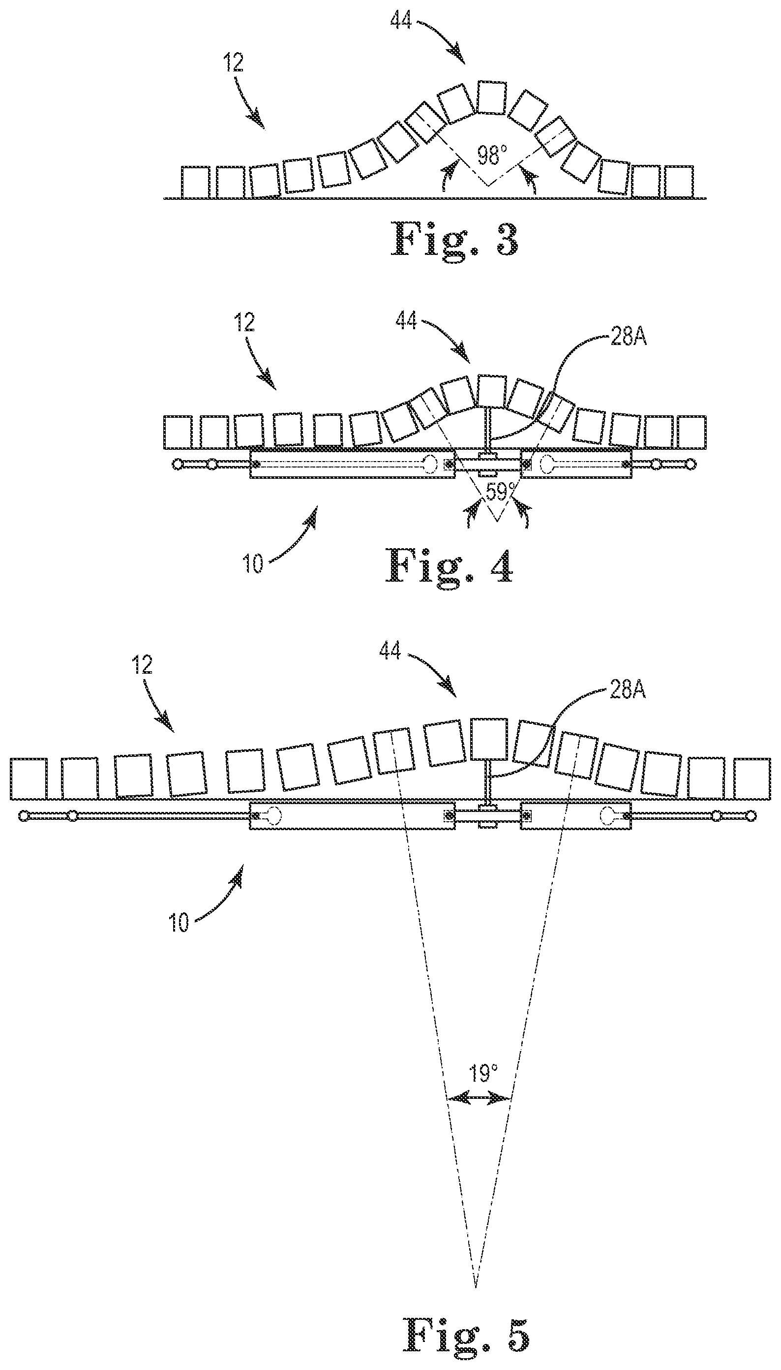
FIG. 3 is a schematic view of a scoliotic spine before correction with the system of FIG. 1, according to some embodiments.
FIG. 4 shows the spine of FIG. 3 after application of the system of FIG. 1, according to some embodiments.
FIG. 5 shows the spine and system of FIG. 4 following spinal growth and elongation of the system, according to some embodiments.
FIG. 6 is a schematic view of another corrective system secured along a spine tending to exhibit a defective curvature with a concave aspect, according to some embodiments.
FIG. 7 is schematic view of another corrective system secured along a spine tending to exhibit a defective curvature with a concave aspect, according to some embodiments.
FIG. 8 is a top view of a dual-ring connector of the systems of FIGS. 6 and 7, according to some embodiments.
FIG. 9 is a front view of the dual-ring connector of FIG. 8, according to some embodiments.
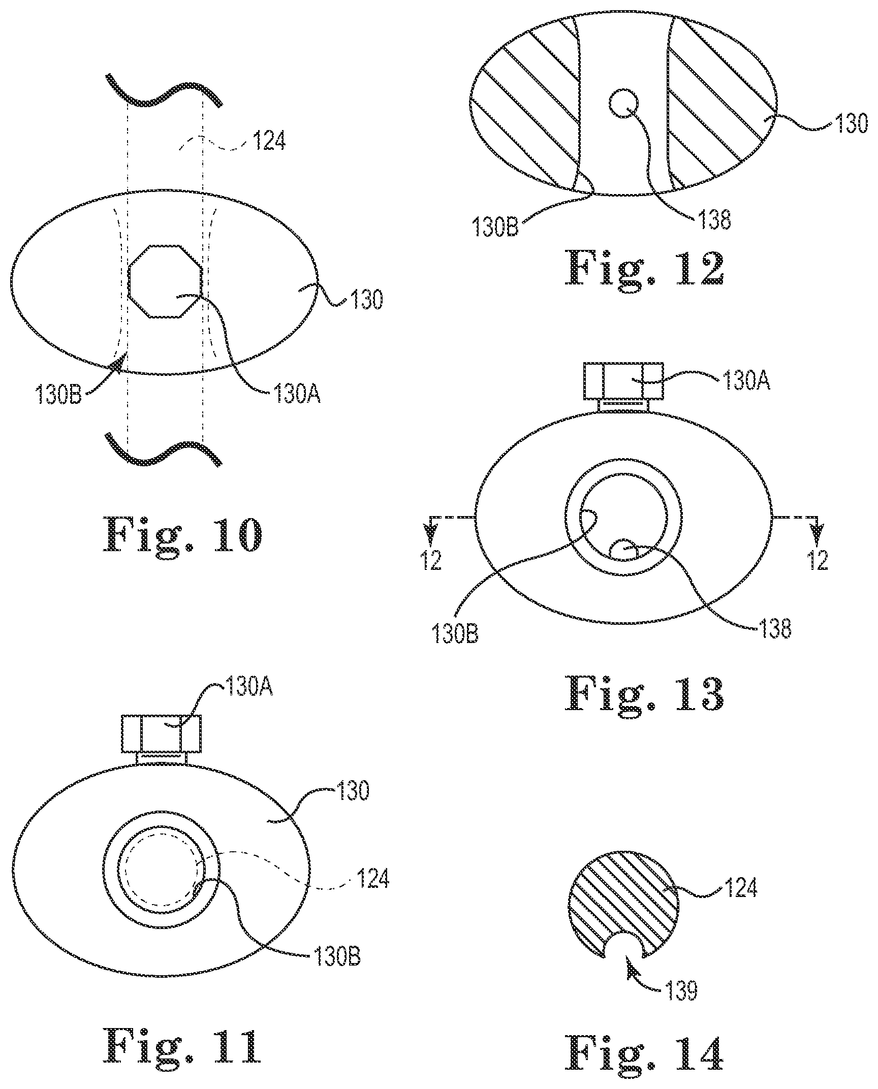
FIG. 10 is a top view of a single-ring connector of the systems of FIGS. 6 and 7, according to some embodiments.
FIG. 11 is a front view of the single-ring connector of FIG. 10, according to some embodiments.
FIG. 12 is a top view of a lateral cross-section of another single-ring connector of the systems of FIGS. 6 and 7, according to some embodiments.
FIG. 13 is a front view of the single-ring connector of FIG. 12, according to some embodiments.
FIG. 14 shows a cross-section of a rod, according to some embodiments.
As previously indicated, this description of the drawings is not meant to be limiting in nature.
DETAILED DESCRIPTION
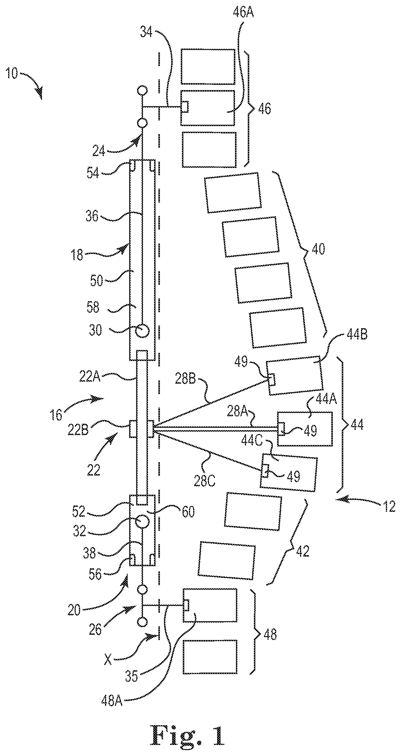
FIG. 1 is a schematic view of a system 10 for growth directed correction of a spine 12 via control of one or more apical vertebrae. The system 10 is secured to a spine 12 along a concave aspect of its defective curvature. In some embodiments, the system 10 includes a hosting connector assembly 16 including a first connector 18, a second connector 20, and a middle assembling segment 22. In the various embodiments, the system 10 further includes a first rod 24, a second rod 26, and an intermediate connector assembly 28. FIG. 2 shows the first connector 18 and portions of the first rod 24 and the middle assembling segment 22.
The first and second rods 24, 26 are adapted to extend along the spine 12 and optionally differ in length as shown in FIG. 1, although in other embodiments the first and second rods are substantially similar in length. In some embodiments, rod length is selected to allow a desired degree of growth of the spine 12. The rods 24, 26 each optionally include an enlarged stop feature 30, 32 having a larger diameter than adjacent portions of the respective rods 24, 26. In some embodiments, the stop features 30, 32 of the rods 24, 26 are thicker, shorter portions (e.g., with smooth rounded outline) which are hosted by wider areas of the connectors 18, 20 and are allowed to slide within the respective connectors 18, 20 until they abut narrower parts of the connectors. Each of the rods 24, 26 also includes thinner longer portions 36, 38.
As shown schematically in FIG. 1, the spine 12 generally includes five portions, where a defective segment of the spine 12 includes a proximal, or upper portion 40; a distal, or lower portion 42; and an apical portion, or apex 44. Above and below the defective segment 40, 42, 44, the spine 12 has a first portion 46 including one or more stabilizing vertebrae (e.g., a first vertebra 46A) and a second portion 48 including one or more stabilizing vertebrae (e.g., a second vertebra 48A). In some embodiments, the stabilizing vertebrae are substantially aligned and are optionally fused during, prior to, or after assembly of the system 10. In turn, the apical portion 44 includes one or more vertebrae at the apex of the defect (e.g., a third vertebra 44A, a fourth vertebra 44B, and a fifth vertebra 44C).
The thinner portions 36, 38 of the rods 24, 26 are adapted to host means of spinal fixation 34, 35, such as pedicle screws or hooks, to the first and second portions 46, 48 of spine 12 at both ends of the defective segment 40, 42, 44. For example, in some embodiments, the means of spinal fixation 34, 35 include pedicle screws or hooks used to secure the thinner longer portions 36, 38 of the rods 24, 26 to one or more vertebrae in each of the first and second portions 46, 48, respectively, of the spine 12. If desired, each of the thinner longer portions 36, 38 is secured to the first and second vertebrae 46A, 48A, respectively, of the first and second portions 46, 48. In some embodiments, one or both of the thinner longer portions 36, 38 are secured to multiple vertebrae, such as two adjacent stabilizing vertebrae of the first and second portions 46, 48, respectively (e.g., to provide additional support to the system 10).
In some embodiments, the middle assembling segment 22 includes a body portion 22A, such as a rod, a plate, or other structure for spanning between the first and second connectors 18, 20 and to which a vertebra (e.g., a third vertebra 44A in the apical portion 44) can be tensioned. The middle assembling segment 22 also optionally includes an interconnect portion 22B, such as a collar or a head of a pedicle screw, for connecting to the body portion 22A.
In some embodiments, the intermediate connector assembly 28 includes one or more elongate members, such as first elongate member 28A, second elongate member 28B, and third elongate member 28C. The elongate members 28A, 28B, 28C optionally include one or more cables, wires, pedicle screws, hooks, rods, and/or other means for spanning between the interconnect portion 22B of the middle assembling segment 22 and the apical portion 44. The elongate members 28A, 28B, 28C are optionally connected to the third, fourth, and fifth vertebrae 44A, 44B, 44C of the apical portion 44, respectively, by fastening means 49, such as threaded fasteners, adhesives, hooks, sublaminar wires, and/or others.
The first and second connectors 18, 20 optionally differ in length as shown in FIG. 1, although in other embodiments the connectors 18, 20 are substantially similar in length. The first and second connectors 18, 20 are adapted to extend along a desired spinal segment (e.g., including the upper and lower portions 40, 42). In some embodiments, the lengths of the first and second connectors 18, 20 are selected to allow a desired amount of longitudinal growth of the spine 12, where the connectors 18, 20 are each optionally cylindrical, having inner bores 50, 52 that have narrowed, neck portions 54, 56 and wider portions 58, 60 such that the inner bores 50, 52 include two parts with different diameters.
In some embodiments, the diameters of the wider portions 58, 60 of the bores 50, 52 are larger than the diameters of the thicker, stop features 30, 32 of the rods 24, 26 to allow introduction of the rods 24, 26 into the bores 50, 52, starting with the thinner portions 36, 38 of the rods 24, 26 which are first introduced through the openings into which the body portion 22A of the middle assembling segment 22 is subsequently inserted and secured. The stop features 30, 32 of the rods 24, 26 help retain the rods 24, 26 in the inner bores 50, 52 by engaging the narrowed or necked portions 54, 56 of the connectors 18, 20 and help prevent inadvertent ejection of the rods 24, 26 from the connectors 18, 20.
In some embodiments, each of the connectors 18, 20 includes two means of fixation (e.g., set screws, pins, or others) for selectively locking a longitudinal position of the rods 24, 26 with respect to the first and second connectors 18, 20, respectively. As used herein, "selectively locking" indicates that the longitudinal position is locked and unlocked as desired using the means of fixation of the first and second connectors 18, 20. According to some embodiments, independent control of each of the upper and lower portions 40, 42 of the deformity is achieved by preselecting a desired amount that each of the first and second rods 24, 26 is allowed to travel in the respective first and second connectors 18, 20 (e.g., by selecting a length of the connectors 18, 20 and rods 24, 26) and/or by selectively locking the rods 24, 26 using the means of fixation once a desired amount of growth is achieved.
FIG. 2 shows a first means of fixation 70 and a second means of fixation 72 of the first connector 18, where according to some embodiments the second connector 20 includes similar means of fixation that operate similarly to the first and second means of fixation 70, 72 (see FIGS. 4 and 5). In the embodiment shown in FIG. 2, the first and second means of fixation 70, 72 are located at each end of the connector 18. The second means of fixation 72 (e.g., a set screw) is optionally used to fix the connector 18 to the middle assembling segment 22, the middle assembling segment 22 being received in the central bore 50 of the connector 18. The first means of fixation 70 is a temporary fixation point to fix the connector 18 to the thinner portion 36 of the rod 24 as desired. The means for fixation of the second connector 20 optionally operate similarly and, by fixing the rods 24, 26 to the connectors 18, 20, the rods 24, 26, and connectors 18, 20 can be handled as one piece for ease of use during their insertion in the index surgery. Following insertion, the first means of fixation 70 of the first connector 18 and the first means of fixation (not shown) of the second connector 20 are released (e.g., unscrewed and/or removed) at the end of the procedure to disengage the connectors 18, 20 from the rods 24, 26 to allow for gradual sliding of the rods 24, 26 within the connectors 18, 20 with growth of the spine 12.
The diameters of the narrower, or thinner portions 36, 38 of the rods 24, 26 allow the thinner portions 36, 38 of the rods 24, 26 to go through the bores 50, 52, while the thicker stop features 30, 32 prevent the rods 24, 26 from ejecting from the bores 50, 52 and limit sliding of the rods 24, 26 to a desired range. In other words, the rods 24, 26 will slide in the connectors 18, 20 with the thicker parts of the rods 24, 26 moving out into the wider parts 58, 60 of the bores 50, 52 of the connectors 18, 20 until they abut against the narrower, necked portions 54, 56 of the bores 50, 52, preventing the rods 24, 26 from further sliding. At this point, the length of the rods 24, 26 and more generally the system 10 will be exhausted and the system 10 will likely need to be adjusted by exchanging the rods 24, 26 and/or connectors 18, 20 to longer sizes.
In some embodiments, the body portion 22A of the middle assembling segment 22 is introduced into, and fixed to both wider ends of the bores 50, 52 of the connectors 18, 20. Upon assembly and fixation to the first and second vertebrae 46A, 48A, the rods 24, 26, connectors 18, 20, and middle assembling segment 22 define a correction axis X extending between the first and second vertebrae 46A, 48A. The body portion 22A of the middle assembling segment 22 is assembled to the interconnect portion 22B which hosts the intermediate connector assembly 28. As described above, the intermediate connector assembly 28 optionally includes elongate members 28A, 28B, 28C that include one or more of cables, wires, pedicle screws, hooks, or other means for spanning between the middle assembling segment 22 and the intermediate connector assembly 28. The distance between the middle assembling segment 22 and the apical portion 44 can be decreased by shortening the length of this fixation tool to tension or draw the apical portion 44 (e.g., the third vertebra 44A) toward the correction axis X.
Some methods of assembly includes coupling the first and second rods 24, 26 with the first and second connectors 18, 20, and then coupling the first and second connectors 18, 20 together with the middle assembling segment 22. When assembled, the thinner portions 36, 38 of both rods 24, 26 extend out of the narrower openings or necked portions 54, 56 of the corresponding connectors 18, 20. The thinner portions 36, 38 may then be attached to the spine 12 proximal and distal to the spinal deformity via vertebral fixation implants (e.g., hooks, screws, or others) at the first and second vertebrae 46A, 48A. The bigger end of both rods 24, 26 (stop features 30, 32) will each be hosted inside the respective bores 50, 52 of one of the connectors 18, 20 near the wider portions 58, 60 of the bores 50, 52 and beside the middle assembling segment 22 to allow the rods 24, 26 to slide inside the bores 50, 52 during growth of the spine 12. Both wider portions 58, 60 of the bores 50, 52 of the connectors 18, 20 receive the body portion 22A of the middle assembling segment 22 which is then secured within the body portion 22A. The elongate member(s) 28A, 28B, 28C of the intermediate connector 28 are secured to the interconnect portion 22B of the middle assembling segment 22 and the elongate member(s) 28A, 28B, 28C are secured to the third, fourth, and fifth vertebrae 44A, 44B, 44C using the fastening means 49 to thereby fix and control the apical portion 44 with respect to the middle assembling segment 22.
Some methods of growth directed correction of the curvature with the system 10 proceeds as follows. The system 10 is applied and secured to the first portion 46 (e.g., first vertebra 46A), the second portion 48 (e.g., second vertebra 48A), and apical portion 44 (e.g., one or more of the third, fourth, and fifth vertebrae 44A, 44B, 44C), for example, after maximum correction has been achieved by surgery. Then, with growth, both bulkier ends or stop features 30, 32 of the rods 24, 26 will slide outwardly, away from the body portion 22A within the first and second connectors 18, 20 allowing for directed growth of the spine until the rods 24, 26 are exhausted and the bulkier parts, or stop features 30, 32 abut against the necked portions 54, 56 of the connectors 18, 20 and/or until the rods 24, 26 are locked at a desired position via the fixation means (e.g., set screws) of the first and second connectors 18, 20. This interaction allows for spontaneous growth (e.g., several centimeters) and many years of growth while keeping the distance between the middle assembling segment 22 and the apical portion 44. In some embodiments, the distance between the middle assembling segment 22 and the apical portion 44 is reduced using a specific instrument, such as a cable or wire tensioner (not shown).
A schematic representation of a method of growth directed correction is provided in FIGS. 3-5, where FIG. 3 shows the spine 12 having a scoliotic curve (e.g., a severe curve greater than about 90 degrees) prior to application of the system 10. FIG. 4 shows the spine 12 and the system 10 after application of the system 10. As shown in FIG. 4, and according to some embodiments, the system 10 is secured to the spine 12 with some amount of apical correction during fixation (e.g., to a curve of about 59 degrees). In some embodiments, partial correction is accomplished by drawing the apical portion 44 toward the system 10 as part of the apical fixation process. FIG. 5 shows the system 10 and spine 12 following spinal growth (e.g., a few years later) where the spine 12 and the system 10 have elongated causing growth directed correction of the spine 12 resulting gradually and spontaneously without further intervention (e.g., to a curve of about 19 degrees). In some embodiments, however, further intervention following some growth is contemplated to encourage and/or augment correction. For example, such intervention optionally includes reducing the distance between the system 10 and the apical portion 44 by tensioning and/or shortening one or more of associated elongate member(s) 28 (a single elongate member 28A is shown in FIGS. 4 and 5).
Various features and advantages of embodiments of the system 10 should be apparent from the foregoing. For example, in some embodiments, the system 10 is easy to fabricate, is low profile such that it is suitable for all ages, and efficient and effective in use. The system 10 is optionally assembled as a single construct via the temporary means of fixation between the rods 24, 26 and connectors 18, 20, promoting ease of insertion and securement to the spine. Once implanted, the system 10 is optionally designed to work over the course of multiple years without substantial intervention.
In view of the foregoing, various embodiments provide a vertebral system 10 for correction and controlled growth of the spine 12 compromising rod(s) 24, 26, a hosting connector assembly 16, and an intermediate connector assembly 28. Embodiments include rods 24, 26 with different diameters of its both ends, where the bigger ends of the rods 24, 26 are optionally smooth to allow sliding in first and second connectors 18, 20 having end openings of different diameters. The connectors 18, 20 optionally have a wider openings to allow introduction of the rods 24, 26 starting with their thinner then thicker parts inside the connectors 18, 20. The wider opening can accommodate and be fixed to a middle assembling segment 22 of the system 10 via any stable means of fixation (e.g., set screws, threads, or others). In some embodiments, the system 10 includes a middle assembling segment 22 that includes a rod or plate which is attached to the intermediate connector assembly 28, which is in turn secured to the apical portion 44 via vertebral fixation means (e.g., hooks, screws, wires, or other fastening means). The connectors 18, 20 provide temporary fixation (e.g., using set screws, pins, or others) to the rods 24, 26 during assembly and insertion of the system 10. The system 10 is optionally to correct spinal deformities by allowing for growth of the spine 12 and promoting further gradual correction of the deformity with growth.
In some embodiments, the system 10 is used for acute and gradual correction of spinal deformity which allows for spinal growth of the instrumented segment by elongating automatically with growth without the need for any intervention after insertion and connection to the spine 12. The system 10 includes a hosting connector assembly or assemblies 16, special rod(s) 24, 26 and intermediate connector(s) 28. The rods 24, 26 are allowed to slide inside the hosting connector assembly 16, in turn allowing for elongation of the whole system 10 and hence the instrumented part of the spine 12. A middle assembling segment 22 is fixed to the apex 44 of the deformity using an intermediate connector assembly 28 including one or more elongate members 28A, 28B, 28C secured to the apex 44 using fastener means (e.g., pedicle screws, hooks, wires, cables, adhesives, and/or other means) to help prevent progressive rotation, angulation, or other deformity progression.
The distance between the two ends of the system 10 are able to independently increase with time and growth, while the distance between the apex 44 of the deformity and the system 10 is fixed or can be shortened by mean of continuous tension of the apical fixation (e.g., by tensioning the elongate member(s) 28A, 28B, 28C) thereby allowing for gradual spinal deformity curve correction with growth. For example, in some embodiments, first and second connector(s) 18, 20 each have a cavity made of two parts with different diameters and lengths--a longer wider part and shorter narrower one. The connector(s) 18, 20 each have one opening at each end, each opening has a different diameter which corresponds to its adjacent cavity. In some embodiments, each rod 24, 26 has a thicker (bigger diameter) shorter part at the end of the rod 24, 26 with the aim of preventing the rod 24, 26 from dislodging from the smaller end opening of the corresponding connector 18, 20 when the system 10 reaches its maximal length. Each wider cavity of the connector(s) 18, 20 can host and allow the passage of both parts of the rod(s) 24, 26 while the narrower cavity of the connector(s) 18, 20 can host only the thinner part of the rod(s) 24, 26, thereby preventing the thicker end of the rod(s) 24, 26 from passing through the corresponding end opening of the connector(s) 18, 20.
In some embodiments, the middle assembling segment 22 connects the two hosting connectors 18, 20 together by being inserted into and secured within the wider openings and cavities of the connectors 18, 20. The rod(s) 24, 26 are introduced--their thinner parts first--into the wider openings of the connectors 18, 20 and are fixed temporarily therein. The body portion 22A of the middle assembling segment 22 is then inserted into the wider ends and fixed therein to interconnect the two connectors 18, 20 together. In some embodiments, the body portion 22A of the middle assembling segment 22 is a rod shaped, or contoured to conform with a desired shape of the spine 12 in order to promote a proper sagittal contour of the spine 12 and decrease an incidence of implant failure, for example. The middle assembling segment 22 is secured to the apical portion 44 by the intermediate connector 28, which includes fastening means such as pedicle screws, hooks, wires, cables, and/or other fastening means for fastening to the vertebrae at the apex 44 of the deformity. The connector(s) 18, 20 have means of fixation (e.g., set screw, pins, and/or others) proximate each end--at the wider end to fix the connectors 18, 20 to the middle assembling segment 22 and at the narrower end to fix the thinner part of the rods 24, 26 temporarily during assembly and insertion and attachment of the system 10 to the spine 12. In some embodiments, the temporary means of fixation, or selective locking means, are removed at the end of the procedure to allow one or both of the rods 24, 26 to slide in the connectors 18, 20 and to allow the system 10 to elongate.
As referenced above, the system 10 optionally facilitates independent, separate control of each of the upper and lower portions 40, 42 of a deformity, those upper and lower portions 40, 42 being situated proximal and distal to an apical portion 44 of the deformity. For example, a distance between each end of the system 10 and the apical portion 44 increases independently with time and growth of the spine 12, while the distance between the apical portion 44 and the system 10 is generally fixed or selectively adjusted (e.g., by tensioning the apical portion 44 toward the hosting connector assembly 16) allowing for gradual or gross spinal deformity curve correction. The first and second connectors 18, 20 optionally have different lengths, (e.g., to facilitate differing, independent, and preplanned control of the permissible growth and correction of the upper and lower portions 40, 42 of the spine 12). In some methods of differing, independent, and preplanned control, a deformity angle and number of vertebrae included in each of the upper and lower portions 40, 42 are taken into consideration in determining an appropriate amount of travel between the first rod 24 and the first connector 18 and between the second rod 26 and the second connector 20, where each of the first and second rods 24, 26 is able to slide independently of the other rod inside its corresponding connector to facilitate independent elongation of the system 10 along the instrumented portions of the spine 12 above and below the apical portion 44. In some methods of correction, the second mean of fixation of each of the first and second connectors 18, 20 can, at any time after the application of the system 10, be tightened to limit further elongation of the corresponding upper or lower portion 40, 42 of the spine 12. By including means for selectively limiting growth of the upper or lower portions 40, 42 of the spine 12, the system 10 is further adapted to promote independent correction of each of the upper and lower portions 40, 42 as desired.
Various modifications and additions can be made to the exemplary embodiments discussed without departing from the scope of the present invention. For example, a second system (not shown) substantially similar to the system 10 is optionally secured on an opposite side of the spine 12 for additional control. Moreover, while the system 10 is shown secured on a concave lateral aspect of the spine 12, it should be understood that, in some embodiments, the system 10 is secured on a convex lateral aspect of the spine 12.
FIG. 6 shows another system 110 for growth directed correction of a spine 112 (schematically represented by a single line) via control of one or more apical vertebrae. As shown, the system 110 includes a cascaded, or laterally offset feature, as subsequently described. As indicated schematically in FIG. 6, in some embodiments the system 110 is secured to the spine 112 along a concave aspect of its defective curvature. In some embodiments, the system 110 includes a hosting connector assembly 116 including a first connector 118, a second connector 120, and a middle assembling segment 122. In the various embodiments, the system 110 further includes a first rod 124, a second rod 126, and an intermediate connector 128.
The first and second rods 124, 126 are adapted to extend along the spine 112 and optionally differ in length as shown in FIG. 6, although in other embodiments the first and second rods 124, 126 are substantially similar in length. Regardless, in some embodiments, rod length is selected to allow a desired degree of growth of the spine 112.
As indicated, the spine 112 generally includes five portions, where a defective segment of the spine 112 includes a proximal, or upper portion 140; a distal, or lower portion 142; and an apical portion, or apex 144. Above and below the defective segment 140, 142, 144, the spine 112 has a first portion 146 including one or more stabilizing vertebrae and a second portion 148 including one or more stabilizing vertebrae. In some embodiments, the stabilizing vertebrae are substantially aligned and are optionally fused during, prior to, or after assembly of the system 110. In turn, the apical portion 144 includes one or more vertebrae at the apex of the defect.
In some embodiments, the rods 124, 126 are adapted to host means of spinal fixation 134, 135 for securing the first and second portions 146, 148 of spine 112 at both ends of the defective segment 140, 142, 144. In some embodiments, the means of spinal fixation 134, 135 include pedicle screws, hooks, adhesive, or other fastening means used to secure the rods 124, 126 to one or more vertebrae in each of the first and second portions 146, 148.
In some embodiments, the middle assembling segment 122 includes a body portion 122A, such as a rod, a plate, or other structure for spanning between the first and second connectors 118, 120 and to which one or more vertebrae in the apical portion 144 is tensioned. The middle assembling segment 122 also optionally includes an interconnect portion 122B, such as a collar or a head of a pedicle screw or hook, for connecting to the body portion 122A.
In some embodiments, the intermediate connector 128 includes one or more elongate members, such as a first elongate member 128A. The elongate member(s) optionally include one or more cables, wires, pedicle screws, rods, and/or other means for spanning between the middle assembling segment 122 and the apical portion 144.
In some embodiments, the first and second connectors 118, 120 are substantially shorter than the connectors 18, 20 of the system 10. For example, the first and second connectors 118, 120 are optionally about 10 mm in length (i.e., a direction substantially parallel to the longitudinal axes of the respective rods 124, 126) or less. The first connector 118 is adapted to slidably receive the first rod 124 and the middle assembling segment 122. The second connector 120 is adapted to slidably receive the second rod 126 and the middle assembling segment 122. The connectors 118, 120 are optionally substantially similar and thus are described with reference to the first connector 118, where FIGS. 8 and 9 are top and front views, respectively, of the first connector 118.
As shown in FIGS. 8 and 9, the first connector 118 has a dual-ring shape, having a first ring portion 150 and a second ring portion 152, the second ring portion 152 being interconnected with the first ring portion 150. The first and second ring portions 150, 152 are optionally alternatively secured together by a rod or other connector. Indeed, although the two portions 150, 152 are shown as a single piece, in other embodiments the two portions 150, 152 are separate, connected components.
The ring portions 150, 152 include central bores 150A, 152A for receiving the first rod 124 and the middle assembling segment 122, respectively. As shown, the central bores 150A, 152A have entries and exits that are rounded to facilitate rod sliding and/or to avoid binding, for example. As shown, the central bores 150A, 152A are substantially circular and smooth. In other embodiments, the central bores 150A, 152A include a prominence, or chase feature (such as chase feature 138 shown in FIGS. 12 and 13) for inhibiting longitudinal rotation of the rod 124 and/or the body portion 122A in the central bores 150A, 152A. For example, in some embodiments, the rod 124 and/or body portion 122A include a complementary chase feature (such as chase 139 shown in FIG. 14) to the prominence so that the rod 124 and/or body portion 122A and the bores 150A, 152A interlock, stopping longitudinal rotation of the rod 124 and/or body portion 122A. In other embodiments, the rod 124 and body portion 122A and the bores 150A, 152A have complementary, non-circular cross-sections (square, octagonal, or D-shaped, for example) that mate to inhibit rotation of the rod 124 and body portion 122A in the bores 150A, 152A, respectively.
As shown in FIG. 6, each of the connectors 118, 120 includes two means of fixation (e.g., set screws, pins, or others) 118A, 118B and 120A, 120B, respectively, for selectively locking a longitudinal position of the connectors 118, 120 relative to the rods 124, 126 and the middle assembling segment 122. As shown in FIGS. 8 and 9, the means of fixation 118A, 118B are set screws secured into the two portions 150, 152, respectively, such that adjustment of the first means of fixation 118A selectively locks the first rod 124 in the first ring portion 150 and adjustment of the second means of fixation 118B selectively locks the middle assembling segment 122 in the second ring portion 152. For reference, in the schematic views of FIGS. 6 and 7, an open hexagon is indicative that the means of fixation is in an unlocked configuration and a solid hexagon is indicative that the means of fixation is in a locked configuration.
In some embodiments, the system 110 includes stop features 130, 132 that help prevent the rods from sliding toward one another, which could otherwise lead to reduction in the length of the system 110 in the longitudinal direction and loss of correction of the scoliosis angle. For example, the stop features 130, 132 optionally help limit the rods 124, 126 to sliding in a single direction--the direction of growth--and help prevent sliding in an opposite direction that would otherwise reduce overall system length. In some embodiments, the stop features 130, 132 are rings, or collars, that include set screws 130A, 132A for securing the stop features 130, 132 longitudinally along the first and second rods 124, 126, respectively.
In some embodiments, the system 110 also includes stop features 136, 137 that help prevent inadvertent ejection of the rods 124, 126 from the connectors 118, 120. For example, the stop features 136, 137 help ensure that the system 110 does not inadvertently disassemble after sufficient growth is achieved to cause the connectors to reach the ends of the rods 124, 126 and/or under sufficient flexing of the spine 112.
Generally, the stop features 130, 132, 136, 137 are substantially similar to the first and second connectors 118, 120, but rather than first and second ring portions, only a single ring portion is present, according to some embodiments. FIGS. 10 and 11 show the stop feature 130 from top and front views, respectively, the stop features 132, 136, 137 being substantially similar to the stop feature 130 according to some embodiments.
As shown in FIG. 6, each of the stop features 130, 132, 136, 137 includes a means of fixation (e.g., set screws, pins, or others) 130A, 132A, 136A, 137A, respectively, for selectively locking a longitudinal position of the stop features relative to the rods 124, 126. The means of fixation 130A, 132A, 136A, 137A are set screws secured into the stop features 130, 132, 136, 137, respectively. For example, as shown in FIGS. 10 and 11, adjustment of the means of fixation 130A selectively locks the first rod 124 in the stop feature 130. For reference, in the schematic views of FIGS. 6 and 7, an open hexagon is indicative that the means of fixation is in an unlocked configuration and a solid hexagon is indicative that the means of fixation is in a locked configuration.
As shown in FIGS. 10 and 11, the stop feature 130 has a single-ring shape, although multi-ring shapes are contemplated. The stop feature 130 includes a central bore 130B for receiving the first rod 124. As shown, the central bore 130B has an entry and an exit that are rounded to facilitate rod sliding and/or to avoid binding, for example. As shown, the central bore 130B is substantially circular and smooth, although non-rotational features are contemplated as described below.
For example, FIGS. 12 and 13 show the stop feature 130 according to some other embodiments, where FIG. 12 is a cross-sectional view along line 12-12 in FIG. 13. As shown, the central bore 130B includes a prominence, or chase feature 138 for inhibiting longitudinal rotation of the rod 124 in the central bore 130B. The chase feature 138 is optionally a hemi-spherical bump or protrusion into the bore 130B. As shown in FIG. 14, in some embodiments, the rod 124 includes a chase feature 139, such as a longitudinal groove or chase, that is complementary to the chase feature 138 such that the rod 124 and the bore 130B are adapted to interlock, helping prevent longitudinal rotation of the rod 124 in the bore 130B. In other embodiments, the rod 124 and the bore 130B have complementary, non-circular cross-sections (square, octagonal, or D-shaped, for example) that mate to inhibit rotation of the rod 124 in the bore 130B. Although the chase features 138, 139 are shown on the stop feature 130 and rod 124, respectively, it should be understood that the chase features 138, 139 are optionally reversed, with the chase feature 139 on the stop feature 130 and the chase feature 138 on the rod 124.
Regardless, according to some embodiments, independent control of each of the upper and lower portions 140, 142 of the deformity is achieved by preselecting a desired amount that each of the first and second rods 124, 126 is allowed to travel in the respective first and second connectors 118, 120. In some embodiments, the amount of travel is determined by selectively locking the stop features 130, 132, 136, 137 longitudinally along the first and second rods 124, 126 at a desired position to set limits of travel for the first and second rods 124, 126, respectively.
Some methods of assembling the system 110 include coupling the first and second rods 124, 126 with the first and second connectors 118, 120, and then coupling the first and second connectors 118, 120 to the middle assembling segment 122. When assembled, the rods 124, 126 extend out of the corresponding connectors 118, 120, with respective portions of the rods 124, 126 being secured to the spine 112 proximal and distal to the spinal deformity via vertebral fixation implants (e.g., hooks, screws, or others) at the first and second portions 146, 148 of the spine 112. The first rod 124 and the second rod 126 are hosted, or received, inside the bores of the respective connectors 118, 120 and are allowed to slide inside the bores of the corresponding connectors 118, 120 during growth of the spine 112.
Adjacent bores of the connectors 118, 120 receive the middle assembling segment 122 and are selectively locked to the body portion 122A to provide system stability. In the configuration shown in FIG. 6, the middle assembling segment defines a second axis of correction Y that is laterally offset, toward the spine 112, relative to a first axis of correction X defined by the longitudinal axes of the rods 124, 126, the two rods 124, 126 being coaxially aligned to one another according to some embodiments. In some embodiments, this offset brings the middle assembling segment 122 closer to the spine 112 reducing the length needed for the intermediate connector 128. The intermediate connector 128 is then secured to the apex 144 using fastening means such as those previously described (e.g., similar to fastening means 49). The respective stop features 130, 132, 136, 137 are received over the first and second rods 124, 126 and are selectively locked thereto in order to help prevent the rods 124, 126 from sliding toward one another (e.g., to avoid losing an amount of correction already achieved with the system 110) as well as help prevent the rods 124, 126 from sliding out of the connectors 118, 120 (e.g., after sufficient spinal growth and/or during flexing of the spine 112). In some embodiments, an additional set of stop features (not shown) are secured inwardly along the rods (e.g., toward the apical portion 144 of the spine 112) to set limits on the allowed longitudinal expansion of the system 110.
Some methods of growth directed correction of the curvature with the system 110 proceeds as follows. The system 110 is applied and secured to the first portion 146, the second portion 148, and the apical portion 144, for example, after maximum correction has been achieved via surgery. Then, with growth, both of the rods 124, 126 will slide outwardly, away from one another and adjacent to the body portion 122A. During growth, the rods 124, 126 will continue to slide within the first and second connectors 118, 120, allowing for growth-directed correction of the spine 112 until the rods 124, 126 are exhausted and/or until the rods 124, 126 are locked at a desired position via the fixation means of the first and second connectors 118, 120. This interaction allows for spontaneous growth and/or movement (e.g., several centimeters) and many years of growth while maintaining a constant distance between the middle assembling segment 122 and the apical portion 144. In some other embodiments, the distance between the middle assembling segment 122 and the apical portion 144 is periodically reduced during growth using a specific instrument, such as a cable or wire tensioner (not shown).
The system 110, and in particular the relatively short connectors, help facilitate placement of the system 110 in relatively compact areas of the spine 112 (e.g., in scoliotic curved regions which provide little area for longer, more bulky connectors). For example, a dorsal curve or an asymmetric curve regularly exhibits a relatively small distance between the stabilizing vertebrae and the apex in which a connector of about 50 mm in length may not fit. The dual-ring connector is deployable in a very short segment of the spine 112 while allowing for considerable length of rod bending and sliding and, thus, growth directed correction. Moreover, in some embodiments, the stop features 130, 132 are optionally used to direct the force in a single, expanding direction by preventing compression and shortening of the system 110 without interfering with elongation thereof.
FIG. 7 is a schematic of another system 210 for growth directed correction of a spine 212 (schematically indicated by a single line) via control of one or more apical vertebrae. In some embodiments the system 210 is secured to the spine 212 along a concave aspect of its defective curvature. In some embodiments, the system 210 includes a hosting connector assembly 216 including a first connector 218, a second connector 220, and a middle assembling segment 222. In the various embodiments, the system 210 further includes a first rod 224, a second rod 226, and an intermediate connector 228.
The first and second rods 224, 226 are adapted to extend along the spine 212 and optionally differ in length as shown in FIG. 7, although in other embodiments the first and second rods 224, 226 are substantially similar in length. Regardless, in some embodiments, rod length is selected to allow a desired degree of growth of the spine 212.
As indicated, the spine 212 generally includes five portions, where a defective segment of the spine 212 includes a proximal, or upper portion 240; a distal, or lower portion 242; and an apical portion, or apex 244. Above and below the defective segment 240, 242, 244, the spine 212 has a first portion 246 including one or more stabilizing vertebrae and a second portion 248 including one or more stabilizing vertebrae. In some embodiments, the stabilizing vertebrae are substantially aligned and are optionally fused during, prior to, or after assembly of the system 210. In turn, the apical portion 244 includes one or more vertebrae at the apex of the defect.
In some embodiments, the rods 224, 226 are adapted to host means of spinal fixation 234, 235 for securing the first and second portions 246, 248 of spine 212 at both ends of the defective segments 240, 242. In some embodiments, the means of spinal fixation 234, 235 include pedicle screws or hooks used to secure the rods 224, 226 to one or more vertebrae in each of the first and second portions 246, 248.
In some embodiments, the middle assembling segment 222 includes a body portion 222A, such as a rod, a plate, or other structure for spanning between the first and second connectors 218, 220 and to which one or more vertebrae in the apical portion 244 is tensioned. The middle assembling segment 222 also optionally includes an interconnect portion 222B, such as a collar or a head of a pedicle screw or hook, for connecting to the body portion 222A.
In some embodiments, the intermediate connector 228 includes one or more elongate members, such as a first elongate member 228A. The elongate member(s) optionally include one or more cables, wires, pedicle screws, hooks, rods, and/or other means for spanning between the middle assembling segment 222 and the apical portion 244.
In some embodiments, the first and second connectors 218, 220 are substantially similar to the first connector 118 shown in FIGS. 8 and 9, the first and second connectors 218, 220 being substantially shorter than the connectors 18, 20 of the system 10. In particular, the first connector 218 is adapted to slidably receive the first rod 224 and the middle assembling segment 222 and the second connector 220 is adapted to slidably receive the second rod 226 and the middle assembling segment 222, each of the first and second connectors 218, 220 including first and second ring portions 250, 252 and 254, 256, respectively.
The ring portions 250, 252 include central bores for receiving the first rod 224 and the middle assembling segment 222, respectively, and the ring portions 254, 256 include central portions for receiving the second rod 226 and the middle assembling segment 222, respectively. As shown in FIG. 7, each of the connectors 218, 220 includes two means of fixation (e.g., set screws, pins, or others) 218A, 218B and 220A, 220B, respectively, for selectively locking a longitudinal position of the connectors 218, 220 relative to the rods 224, 226 and the middle assembling segment 222. The means of fixation 218A, 218B are optionally set screws secured into the ring portions 250, 252 and 254, 256, respectively. Activation of the first means of fixation 218A selectively locks the first rod 224 in the first ring portion 250 and activation of the second means of fixation 218B selectively locks the middle assembling segment 222 in the second ring portion 252. Activation of the first means of fixation 220A selectively locks the second rod 226 in the first ring portion 254 and activation of the second means of fixation 220B selectively locks the middle assembling segment 222 in the second ring portion 256. For reference, in the schematic views of FIGS. 6 and 7, an open hexagon is indicative that the means of fixation is in an unlocked configuration and a solid hexagon is indicative that the means of fixation is in a locked configuration.
In some embodiments, the system 210 includes stop features 230, 233 that help retain the middle assembling segment 222 in the first and second connector assemblies 218, 220 by preventing inadvertent ejection of the middle assembling segment 222 from the connectors 218, 220 (e.g., after sufficient spinal growth and/or during flexing of the spine 212). The system 210 also includes stop features 231, 232 that help ensure that an achieved amount of correction of the spine 212 is not lost (e.g., due to compressive forces on the patient's spine--such as during standing). In some embodiments, the stop features 230, 231, 232, 233 are rings, or collars, that include set screws 230A, 231A, 232A, 233A for securing the stop features 230, 231, 232, 233 longitudinally along the middle assembling segment 222. In some embodiments, stop features 231, 232 help prevent collapse, or shortening of the system (e.g., under compressive forces of body weight) while stop features 230, 233 help prevent ejection of the middle assembling segment 222 from the connector assemblies 218, 220 once a length of the middle assembling segment 222 has been exhausted from spinal growth.
Generally, the stop features 230, 231, 232, 233 are substantially similar to the first and second connectors 218, 220, but rather than first and second ring portions, only a single ring portion is present, according to some embodiments. Regardless, according to some embodiments, independent control of each of the upper and lower portions 240, 242 of the deformity is achieved by preselecting a desired amount that the system 210 expands, or an amount that each of the first and second rods 224, 226 is allowed to travel along the middle assembling segment 222, by selectively locking the stop features 230, 231, 232, 233 longitudinally at desired positions to set limits of travel for the first and second rods 224, 226, respectively. For example, as shown in FIG. 7, the stop features 230, 231 are locked on the middle assembling segment 222 on opposite sides of the first connector 218 and the stop features 232, 233 are locked on the middle assembling segment 222 on opposite sides of the second connector 220, to limit the travel of first and second connectors relative to the middle assembling segment 222.
Some methods of assembling the system 210 include coupling the first and second rods 224, 226 with the first and second connectors 218, 220, and then coupling the first and second connectors 218, 220 to the middle assembling segment 222. When assembled, the rods 224, 226 extend out of the corresponding connectors 218, 220, with respective portions of the rods 224, 226 being secured to the spine 212 proximal and distal to the spinal deformity via vertebral fixation implants (e.g., hooks, screws, or others) at the first and second portions 246, 248 of the spine 212. A first end 224A of the first rod 224 and a first end 226A of the second rod 226 are hosted inside the bores of the respective connectors 218, 220 and are selectively locked inside the bores of the corresponding connectors 218, 220 during growth of the spine 212.
Adjacent bores of the connectors 218, 220 slidably receive the middle assembling segment 222 (although the connectors 218, 220 are optionally locked to the middle assembling segment 222 during implantation to provide a rigid construct that is more readily handled, or to provide system stability). In the configuration shown in FIG. 7, the middle assembling segment 222 defines a second axis of correction Y that is laterally offset, toward the spine 212, relative to a first axis of correction X defined by the longitudinal axes of the rods 224, 226, the two rods 224, 226 being coaxially aligned to one another according to some embodiments. In some embodiments, this offset brings the middle assembling segment 222 closer to the spine 212 reducing the length needed for the intermediate connector 228. The intermediate connector 228 is then secured to the apex 244 using fastening means such as those previously described (e.g., similar to fastening means 49).
The respective stop features 230, 231, 232, 233 are received over the intermediate connector 228 and are selectively locked thereto in order to set limits between which the first and connectors 218, 220 slide on the middle assembling segment.
Some methods of growth directed correction of the curvature with the system 210 proceeds as follows. The system 210 is applied and secured to the first portion 246, the second portion 248, and the apical portion 244, for example, after maximum correction has been achieved via surgery. Then, with growth, both of the rods 224, 226 will slide outwardly, away from one another and adjacent to the body portion 222A. During growth, the rods 224, 226, and in particular the first and second connectors 218, 220, will continue to slide along the middle assembling segment 222, allowing for growth-directed correction of the spine 212 until the limit of travel is exhausted and/or until the rods 224, 226 are locked at a desired position via the fixation means of the first and second connectors 218, 220. This interaction allows for spontaneous growth and/or movement (e.g., several centimeters) and many years of growth while maintaining a constant distance between the middle assembling segment 222 and the apical portion 244. In some other embodiments, the distance between the middle assembling segment 222 and the apical portion 244 is periodically reduced during growth using a specific instrument, such as a cable or wire tensioner (not shown).
The system 210, and in particular the relatively short connectors, help facilitate placement of the system 210 in relatively compact areas of the spine 212 (e.g., in scoliotic curved regions which provide little area for longer, more bulky connectors). For example, a dorsal curve or an asymmetric curve regularly exhibits a relatively small distance between the stabilizing vertebrae and the apex in which a connector of about 50 mm in length may not fit. The dual-ring connector is deployable in a very short segment of the spine 212 while allowing for considerable length of rod bending and sliding and, thus, growth directed correction. Moreover, in some embodiments, the stop features 230, 232 are optionally used to direct the force in a single, expanding direction by preventing compression and shortening of the system 210 without interfering with elongation thereof.
Various features and advantages of embodiments of the systems 10, 110, 210 should be apparent from the foregoing. For example, in some embodiments, such systems are easy to fabricate, are low profile to be suitable for all ages, and efficient and effective in use. The systems are optionally assembled and implanted as a single construct via the various means of fixation, with subsequent unlocking of the system to permit the desired expansion, promoting both ease of insertion and ready securement to the spine. Once implanted, the systems are designed to work over the course of multiple years without substantial intervention.
The range of indication of embodiments of the systems is wide enough to include any type of early onset spinal deformity of any etiology from the very young ages to the adolescent growth spurt, for example. One exemplary indication is early onset scoliosis where the systems are used in young children to allow for growth of the spine, trunk, chest, and lungs while preventing progression of the scoliotic curve and even correcting the curve spontaneously with growth. The systems can also be used in small and moderate sized curves during the adolescent period before severe progression as a kind of internal bracing to help prevent further progression of these defective curves until a child's growth spurt finishes. In some embodiments, once the growth spurt has ended, the systems are removed, leaving a non-fused, relatively flexible, corrected spine.
While the embodiments described above refer to particular features, the scope of this invention also includes embodiments having different combinations of features and embodiments that do not include all of the described features. Accordingly, the scope of the present invention is intended to embrace all such alternatives, modifications, and variations as fall within the scope of the claims, together with all equivalents thereof.
* * * * *
D00000
D00001
D00002
D00003
D00004
D00005
D00006
XML
uspto.report is an independent third-party trademark research tool that is not affiliated, endorsed, or sponsored by the United States Patent and Trademark Office (USPTO) or any other governmental organization. The information provided by uspto.report is based on publicly available data at the time of writing and is intended for informational purposes only.
While we strive to provide accurate and up-to-date information, we do not guarantee the accuracy, completeness, reliability, or suitability of the information displayed on this site. The use of this site is at your own risk. Any reliance you place on such information is therefore strictly at your own risk.
All official trademark data, including owner information, should be verified by visiting the official USPTO website at www.uspto.gov. This site is not intended to replace professional legal advice and should not be used as a substitute for consulting with a legal professional who is knowledgeable about trademark law.