Ultrasonic surgical instruments having offset blades
Messerly , et al. November 24, 2
U.S. patent number 10,842,522 [Application Number 15/211,402] was granted by the patent office on 2020-11-24 for ultrasonic surgical instruments having offset blades. This patent grant is currently assigned to Ethicon LLC. The grantee listed for this patent is Ethicon Endo-Surgery, LLC. Invention is credited to William E. Clem, Frederick Estera, Gregory W. Johnson, Cory G Kimball, Jeffrey D. Messerly, Foster B. Stulen, William B. Weisenburgh, II.


View All Diagrams
| United States Patent | 10,842,522 |
| Messerly , et al. | November 24, 2020 |
Ultrasonic surgical instruments having offset blades
Abstract
Ultrasonic surgical instruments having angularly and/or linearly off-set blades are described. The angularly and/or linearly off-set blades may facilitate increased surgical site access, visibility, and manipulability.
| Inventors: | Messerly; Jeffrey D. (Cincinnati, OH), Kimball; Cory G (Hamilton, OH), Clem; William E. (Bozeman, MT), Johnson; Gregory W. (Milford, OH), Estera; Frederick (Cincinnati, OH), Weisenburgh, II; William B. (Maineville, OH), Stulen; Foster B. (Mason, OH) | ||||||||||
|---|---|---|---|---|---|---|---|---|---|---|---|
| Applicant: |
|
||||||||||
| Assignee: | Ethicon LLC (Guaynabo,
PR) |
||||||||||
| Family ID: | 1000005199674 | ||||||||||
| Appl. No.: | 15/211,402 | ||||||||||
| Filed: | July 15, 2016 |
Prior Publication Data
| Document Identifier | Publication Date | |
|---|---|---|
| US 20180014848 A1 | Jan 18, 2018 | |
| Current U.S. Class: | 1/1 |
| Current CPC Class: | A61B 17/320092 (20130101); A61N 7/00 (20130101); A61B 17/320068 (20130101); A61B 2017/320095 (20170801); A61B 2017/320072 (20130101); A61B 2017/320074 (20170801); A61B 2018/00589 (20130101); A61B 2017/00738 (20130101); A61B 2017/320094 (20170801); A61B 2017/320088 (20130101) |
| Current International Class: | A61B 17/32 (20060101); A61N 7/00 (20060101); A61B 18/00 (20060101); A61B 17/00 (20060101) |
References Cited [Referenced By]
U.S. Patent Documents
| 969528 | September 1910 | Disbrow |
| 1570025 | January 1926 | Young |
| 1813902 | July 1931 | Bovie |
| 2188497 | January 1940 | Calva |
| 2366274 | January 1945 | Luth et al. |
| 2425245 | August 1947 | Johnson |
| 2442966 | June 1948 | Wallace |
| 2458152 | January 1949 | Eakins |
| 2510693 | June 1950 | Green |
| 2597564 | May 1952 | Bugg |
| 2704333 | March 1955 | Calosi et al. |
| 2736960 | March 1956 | Armstrong |
| 2743726 | May 1956 | Grieshaber |
| 2748967 | June 1956 | Roach |
| 2845072 | July 1958 | Shafer |
| 2849788 | September 1958 | Creek |
| 2867039 | January 1959 | Zach |
| 2874470 | February 1959 | Richards |
| 2990616 | July 1961 | Balamuth et al. |
| RE25033 | August 1961 | Balamuth et al. |
| 3015961 | January 1962 | Roney |
| 3033407 | May 1962 | Alfons |
| 3053124 | September 1962 | Balamuth et al. |
| 3082805 | March 1963 | Royce |
| 3166971 | January 1965 | Stoecker |
| 3322403 | May 1967 | Murphy |
| 3432691 | March 1969 | Shoh |
| 3433226 | March 1969 | Boyd |
| 3489930 | January 1970 | Shoh |
| 3513848 | May 1970 | Winston et al. |
| 3514856 | June 1970 | Camp et al. |
| 3525912 | August 1970 | Wallin |
| 3526219 | September 1970 | Balamuth |
| 3554198 | January 1971 | Tatoian et al. |
| 3580841 | May 1971 | Cadotte et al. |
| 3606682 | September 1971 | Camp et al. |
| 3614484 | October 1971 | Shoh |
| 3616375 | October 1971 | Inoue |
| 3629726 | December 1971 | Popescu |
| 3636943 | January 1972 | Balamuth |
| 3668486 | June 1972 | Silver |
| 3702948 | November 1972 | Balamuth |
| 3703651 | November 1972 | Blowers |
| 3776238 | December 1973 | Peyman et al. |
| 3777760 | December 1973 | Essner |
| 3792701 | February 1974 | Kloz et al. |
| 3805787 | April 1974 | Banko |
| 3809977 | May 1974 | Balamuth et al. |
| 3830098 | August 1974 | Antonevich |
| 3854737 | December 1974 | Gilliam, Sr. |
| 3862630 | January 1975 | Balamuth |
| 3875945 | April 1975 | Friedman |
| 3885438 | May 1975 | Harris, Sr. et al. |
| 3900823 | August 1975 | Sokal et al. |
| 3918442 | November 1975 | Nikolaev et al. |
| 3924335 | December 1975 | Balamuth et al. |
| 3946738 | March 1976 | Newton et al. |
| 3955859 | May 1976 | Stella et al. |
| 3956826 | May 1976 | Perdreaux, Jr. |
| 4005714 | February 1977 | Hiltebrandt |
| 4012647 | March 1977 | Balamuth et al. |
| 4034762 | July 1977 | Cosens et al. |
| 4058126 | November 1977 | Leveen |
| 4074719 | February 1978 | Semm |
| 4085893 | April 1978 | Durley, III |
| 4156187 | May 1979 | Murry et al. |
| 4167944 | September 1979 | Banko |
| 4188927 | February 1980 | Harris |
| 4193009 | March 1980 | Durley, III |
| 4200106 | April 1980 | Douvas et al. |
| 4203430 | May 1980 | Takahashi |
| 4203444 | May 1980 | Bonnell et al. |
| 4220154 | September 1980 | Semm |
| 4237441 | December 1980 | van Konynenburg et al. |
| 4281785 | August 1981 | Brooks |
| 4300083 | November 1981 | Heiges |
| 4302728 | November 1981 | Nakamura |
| 4304987 | December 1981 | van Konynenburg |
| 4306570 | December 1981 | Matthews |
| 4314559 | February 1982 | Allen |
| 4445063 | April 1984 | Smith |
| 4463759 | August 1984 | Garito et al. |
| 4491132 | January 1985 | Aikins |
| 4492231 | January 1985 | Auth |
| 4494759 | January 1985 | Kieffer |
| 4504264 | March 1985 | Kelman |
| 4512344 | April 1985 | Barber |
| 4526571 | July 1985 | Wuchinich |
| 4535773 | August 1985 | Yoon |
| 4541638 | September 1985 | Ogawa et al. |
| 4545374 | October 1985 | Jacobson |
| 4545926 | October 1985 | Fouts, Jr. et al. |
| 4550870 | November 1985 | Krumme et al. |
| 4553544 | November 1985 | Nomoto et al. |
| 4562838 | January 1986 | Walker |
| 4574615 | March 1986 | Bower et al. |
| 4582236 | April 1986 | Hirose |
| 4617927 | October 1986 | Manes |
| 4633119 | December 1986 | Thompson |
| 4634420 | January 1987 | Spinosa et al. |
| 4640279 | February 1987 | Beard |
| 4641053 | February 1987 | Takeda |
| 4646738 | March 1987 | Trott |
| 4646756 | March 1987 | Watmough et al. |
| 4649919 | March 1987 | Thimsen et al. |
| 4662068 | May 1987 | Polonsky |
| 4674502 | June 1987 | Imonti |
| 4708127 | November 1987 | Abdelghani |
| 4712722 | December 1987 | Hood et al. |
| 4735603 | April 1988 | Goodson et al. |
| 4750488 | June 1988 | Wuchinich et al. |
| 4761871 | August 1988 | O'Connor et al. |
| 4808154 | February 1989 | Freeman |
| 4819635 | April 1989 | Shapiro |
| 4827911 | May 1989 | Broadwin et al. |
| 4830462 | May 1989 | Karny et al. |
| 4832683 | May 1989 | Idemoto et al. |
| 4836186 | June 1989 | Scholz |
| 4838853 | June 1989 | Parisi |
| 4844064 | July 1989 | Thimsen et al. |
| 4849133 | July 1989 | Yoshida et al. |
| 4850354 | July 1989 | McGurk-Burleson et al. |
| 4852578 | August 1989 | Companion et al. |
| 4860745 | August 1989 | Farin et al. |
| 4862890 | September 1989 | Stasz et al. |
| 4865159 | September 1989 | Jamison |
| 4867157 | September 1989 | McGurk-Burleson et al. |
| 4878493 | November 1989 | Pasternak et al. |
| 4880015 | November 1989 | Nierman |
| 4881550 | November 1989 | Kothe |
| 4896009 | January 1990 | Pawlowski |
| 4903696 | February 1990 | Stasz et al. |
| 4910389 | March 1990 | Sherman et al. |
| 4915643 | April 1990 | Samejima et al. |
| 4920978 | May 1990 | Colvin |
| 4922902 | May 1990 | Wuchinich et al. |
| 4936842 | June 1990 | D'Amelio et al. |
| 4954960 | September 1990 | Lo et al. |
| 4965532 | October 1990 | Sakurai |
| 4979952 | December 1990 | Kubota et al. |
| 4981756 | January 1991 | Rhandhawa |
| 4983160 | January 1991 | Steppe et al. |
| 5013956 | May 1991 | Kurozumi et al. |
| 5015227 | May 1991 | Broadwin et al. |
| 5020514 | June 1991 | Heckele |
| 5026370 | June 1991 | Lottick |
| 5026387 | June 1991 | Thomas |
| 5035695 | July 1991 | Weber, Jr. et al. |
| 5042707 | August 1991 | Taheri |
| 5047043 | September 1991 | Kubota |
| 5061269 | October 1991 | Muller |
| 5084052 | January 1992 | Jacobs |
| 5099840 | March 1992 | Goble et al. |
| 5104025 | April 1992 | Main et al. |
| 5105117 | April 1992 | Yamaguchi |
| 5106538 | April 1992 | Barma et al. |
| 5108383 | April 1992 | White |
| 5109819 | May 1992 | Custer et al. |
| 5112300 | May 1992 | Ureche |
| 5123903 | June 1992 | Quaid et al. |
| 5126618 | June 1992 | Takahashi et al. |
| D327872 | July 1992 | McMills et al. |
| 5152762 | October 1992 | McElhenney |
| 5156633 | October 1992 | Smith |
| 5160334 | November 1992 | Billings et al. |
| 5162044 | November 1992 | Gahn et al. |
| 5163421 | November 1992 | Bernstein et al. |
| 5163537 | November 1992 | Radev |
| 5167619 | December 1992 | Wuchinich |
| 5167725 | December 1992 | Clark et al. |
| 5172344 | December 1992 | Ehrlich |
| 5174276 | December 1992 | Crockard |
| D332660 | January 1993 | Rawson et al. |
| 5176677 | January 1993 | Wuchinich |
| 5176695 | January 1993 | Dulebohn |
| 5184605 | February 1993 | Grzeszykowski |
| 5188102 | February 1993 | Idemoto et al. |
| D334173 | March 1993 | Liu et al. |
| 5190541 | March 1993 | Abele et al. |
| 5196007 | March 1993 | Ellman et al. |
| 5205459 | April 1993 | Brinkerhoff et al. |
| 5209719 | May 1993 | Baruch et al. |
| 5213103 | May 1993 | Martin et al. |
| 5213569 | May 1993 | Davis |
| 5214339 | May 1993 | Naito |
| 5217460 | June 1993 | Knoepfler |
| 5218529 | June 1993 | Meyer et al. |
| 5221282 | June 1993 | Wuchinich |
| 5222937 | June 1993 | Kagawa |
| 5226909 | July 1993 | Evans et al. |
| 5226910 | July 1993 | Kajiyama et al. |
| 5234428 | August 1993 | Kaufman |
| 5234436 | August 1993 | Eaton et al. |
| 5241236 | August 1993 | Sasaki et al. |
| 5241968 | September 1993 | Slater |
| 5242460 | September 1993 | Klein et al. |
| 5254129 | October 1993 | Alexander |
| 5257988 | November 1993 | L'Esperance, Jr. |
| 5258006 | November 1993 | Rydell et al. |
| 5261922 | November 1993 | Hood |
| 5263957 | November 1993 | Davison |
| 5264925 | November 1993 | Shipp et al. |
| 5275166 | January 1994 | Vaitekunas et al. |
| 5275607 | January 1994 | Lo et al. |
| 5275609 | January 1994 | Pingleton et al. |
| 5282800 | February 1994 | Foshee et al. |
| 5282817 | February 1994 | Hoogeboom et al. |
| 5285795 | February 1994 | Ryan et al. |
| 5285945 | February 1994 | Brinkerhoff et al. |
| 5290286 | March 1994 | Parins |
| 5300068 | April 1994 | Rosar et al. |
| 5304115 | April 1994 | Pflueger et al. |
| D347474 | May 1994 | Olson |
| 5307976 | May 1994 | Olson et al. |
| 5309927 | May 1994 | Welch |
| 5312023 | May 1994 | Green et al. |
| 5312425 | May 1994 | Evans et al. |
| 5318563 | June 1994 | Malis et al. |
| 5318564 | June 1994 | Eggers |
| 5318570 | June 1994 | Hood et al. |
| 5318589 | June 1994 | Lichtman |
| 5322055 | June 1994 | Davison et al. |
| 5324299 | June 1994 | Davison et al. |
| 5326013 | July 1994 | Green et al. |
| 5326342 | July 1994 | Pflueger et al. |
| 5330471 | July 1994 | Eggers |
| 5330502 | July 1994 | Hassler et al. |
| 5339723 | August 1994 | Huitema |
| 5342359 | August 1994 | Rydell |
| 5344420 | September 1994 | Hilal et al. |
| 5345937 | September 1994 | Middleman et al. |
| 5346502 | September 1994 | Estabrook et al. |
| 5353474 | October 1994 | Good et al. |
| 5357164 | October 1994 | Imabayashi et al. |
| 5357423 | October 1994 | Weaver et al. |
| 5359994 | November 1994 | Krauter et al. |
| 5361583 | November 1994 | Huitema |
| 5366466 | November 1994 | Christian et al. |
| 5368557 | November 1994 | Nita et al. |
| 5370645 | December 1994 | Klicek et al. |
| 5371429 | December 1994 | Manna |
| 5374813 | December 1994 | Shipp |
| D354564 | January 1995 | Medema |
| 5381067 | January 1995 | Greenstein et al. |
| 5383874 | January 1995 | Jackson et al. |
| 5387207 | February 1995 | Dyer et al. |
| 5387215 | February 1995 | Fisher |
| 5389098 | February 1995 | Tsuruta et al. |
| 5394187 | February 1995 | Shipp |
| 5395312 | March 1995 | Desai |
| 5395363 | March 1995 | Billings et al. |
| 5395364 | March 1995 | Anderhub et al. |
| 5396266 | March 1995 | Brimhall |
| 5396900 | March 1995 | Slater et al. |
| 5403312 | April 1995 | Yates et al. |
| 5403334 | April 1995 | Evans et al. |
| 5408268 | April 1995 | Shipp |
| 5409453 | April 1995 | Lundquist |
| D358887 | May 1995 | Feinberg |
| 5411481 | May 1995 | Allen et al. |
| 5417709 | May 1995 | Slater |
| 5419761 | May 1995 | Narayanan et al. |
| 5421829 | June 1995 | Olichney et al. |
| 5423844 | June 1995 | Miller |
| 5428504 | June 1995 | Bhatla |
| 5429131 | July 1995 | Scheinman et al. |
| 5438997 | August 1995 | Sieben et al. |
| 5443463 | August 1995 | Stern et al. |
| 5445638 | August 1995 | Rydell et al. |
| 5445639 | August 1995 | Kuslich et al. |
| 5449370 | September 1995 | Vaitekunas |
| 5451220 | September 1995 | Ciervo |
| 5451227 | September 1995 | Michaelson |
| 5456684 | October 1995 | Schmidt et al. |
| 5458598 | October 1995 | Feinberg et al. |
| 5465895 | November 1995 | Knodel et al. |
| 5471988 | December 1995 | Fujio et al. |
| 5472443 | December 1995 | Cordis et al. |
| 5476479 | December 1995 | Green et al. |
| 5478003 | December 1995 | Green et al. |
| 5480409 | January 1996 | Riza |
| 5483501 | January 1996 | Park et al. |
| 5484436 | January 1996 | Eggers et al. |
| 5486162 | January 1996 | Brumbach |
| 5486189 | January 1996 | Mudry et al. |
| 5490860 | February 1996 | Middle et al. |
| 5496317 | March 1996 | Goble et al. |
| 5500216 | March 1996 | Julian et al. |
| 5501654 | March 1996 | Failla et al. |
| 5504650 | April 1996 | Katsui et al. |
| 5505693 | April 1996 | Mackool |
| 5507738 | April 1996 | Ciervo |
| 5509922 | April 1996 | Aranyi et al. |
| 5511556 | April 1996 | DeSantis |
| 5520704 | May 1996 | Castro et al. |
| 5522839 | June 1996 | Pilling |
| 5527331 | June 1996 | Kresch et al. |
| 5531744 | July 1996 | Nardella et al. |
| 5540681 | July 1996 | Strul et al. |
| 5540693 | July 1996 | Fisher |
| 5542916 | August 1996 | Hirsch et al. |
| 5553675 | September 1996 | Pitzen et al. |
| 5558671 | September 1996 | Yates |
| 5562609 | October 1996 | Brumbach |
| 5562610 | October 1996 | Brumbach |
| 5562659 | October 1996 | Morris |
| 5563179 | October 1996 | Stone et al. |
| 5569164 | October 1996 | Lurz |
| 5571121 | November 1996 | Heifetz |
| 5573424 | November 1996 | Poppe |
| 5573534 | November 1996 | Stone |
| 5577654 | November 1996 | Bishop |
| 5582618 | December 1996 | Chin et al. |
| 5584830 | December 1996 | Ladd et al. |
| 5591187 | January 1997 | Dekel |
| 5593414 | January 1997 | Shipp et al. |
| 5599350 | February 1997 | Schulze et al. |
| 5601601 | February 1997 | Tal et al. |
| 5603773 | February 1997 | Campbell |
| 5607436 | March 1997 | Pratt et al. |
| 5607450 | March 1997 | Zvenyatsky et al. |
| 5609573 | March 1997 | Sandock |
| 5611813 | March 1997 | Lichtman |
| 5618304 | April 1997 | Hart et al. |
| 5618307 | April 1997 | Donlon et al. |
| 5618492 | April 1997 | Auten et al. |
| 5620447 | April 1997 | Smith et al. |
| 5624452 | April 1997 | Yates |
| 5626587 | May 1997 | Bishop et al. |
| 5626595 | May 1997 | Sklar et al. |
| 5628760 | May 1997 | Knoepfler |
| 5630420 | May 1997 | Vaitekunas |
| 5632432 | May 1997 | Schulze et al. |
| 5632717 | May 1997 | Yoon |
| 5640741 | June 1997 | Yano |
| D381077 | July 1997 | Hunt |
| 5647871 | July 1997 | Levine et al. |
| 5649937 | July 1997 | Bito et al. |
| 5651780 | July 1997 | Jackson et al. |
| 5653713 | August 1997 | Michelson |
| 5658281 | August 1997 | Heard |
| 5662662 | September 1997 | Bishop et al. |
| 5662667 | September 1997 | Knodel |
| 5665085 | September 1997 | Nardella |
| 5665100 | September 1997 | Yoon |
| 5669922 | September 1997 | Hood |
| 5674219 | October 1997 | Monson et al. |
| 5674220 | October 1997 | Fox et al. |
| 5674235 | October 1997 | Parisi |
| 5678568 | October 1997 | Uchikubo et al. |
| 5688270 | November 1997 | Yates et al. |
| 5690269 | November 1997 | Bolanos et al. |
| 5693051 | December 1997 | Schulze et al. |
| 5694936 | December 1997 | Fujimoto et al. |
| 5695510 | December 1997 | Hood |
| 5700261 | December 1997 | Brinkerhoff |
| 5704534 | January 1998 | Huitema et al. |
| 5709680 | January 1998 | Yates et al. |
| 5711472 | January 1998 | Bryan |
| 5713896 | February 1998 | Nardella |
| 5715817 | February 1998 | Stevens-Wright et al. |
| 5716366 | February 1998 | Yates |
| 5717306 | February 1998 | Shipp |
| 5720742 | February 1998 | Zacharias |
| 5720744 | February 1998 | Eggleston et al. |
| 5728130 | March 1998 | Ishikawa et al. |
| 5730752 | March 1998 | Alden et al. |
| 5733074 | March 1998 | Stock et al. |
| 5735848 | April 1998 | Yates et al. |
| 5741226 | April 1998 | Strukel et al. |
| 5743906 | April 1998 | Parins et al. |
| 5752973 | May 1998 | Kieturakis |
| 5755717 | May 1998 | Yates et al. |
| 5762255 | June 1998 | Chrisman et al. |
| 5766164 | June 1998 | Mueller et al. |
| 5772659 | June 1998 | Becker et al. |
| 5776155 | July 1998 | Beaupre et al. |
| 5779701 | July 1998 | McBrayer et al. |
| 5782834 | July 1998 | Lucey et al. |
| 5792135 | August 1998 | Madhani et al. |
| 5792138 | August 1998 | Shipp |
| 5792165 | August 1998 | Klieman et al. |
| 5796188 | August 1998 | Bays |
| 5797941 | August 1998 | Schulze et al. |
| 5797959 | August 1998 | Castro et al. |
| 5800432 | September 1998 | Swanson |
| 5800449 | September 1998 | Wales |
| 5805140 | September 1998 | Rosenberg et al. |
| 5807393 | September 1998 | Williamson, IV et al. |
| 5808396 | September 1998 | Boukhny |
| 5810811 | September 1998 | Yates et al. |
| 5810859 | September 1998 | DiMatteo et al. |
| 5817033 | October 1998 | DeSantis et al. |
| 5817084 | October 1998 | Jensen |
| 5817093 | October 1998 | Williamson, IV et al. |
| 5817119 | October 1998 | Klieman et al. |
| 5823197 | October 1998 | Edwards |
| 5827323 | October 1998 | Klieman et al. |
| 5828160 | October 1998 | Sugishita |
| 5833696 | November 1998 | Whitfield et al. |
| 5836897 | November 1998 | Sakurai et al. |
| 5836909 | November 1998 | Cosmescu |
| 5836943 | November 1998 | Miller, III |
| 5836957 | November 1998 | Schulz et al. |
| 5836990 | November 1998 | Li |
| 5843109 | December 1998 | Mehta et al. |
| 5851212 | December 1998 | Zirps et al. |
| 5853412 | December 1998 | Mayenberger |
| 5858018 | January 1999 | Shipp et al. |
| 5865361 | February 1999 | Milliman et al. |
| 5873873 | February 1999 | Smith et al. |
| 5873882 | February 1999 | Straub et al. |
| 5876401 | March 1999 | Schulze et al. |
| 5878193 | March 1999 | Wang et al. |
| 5879364 | March 1999 | Bromfield et al. |
| 5880668 | March 1999 | Hall |
| 5883615 | March 1999 | Fago et al. |
| 5891142 | April 1999 | Eggers et al. |
| 5893835 | April 1999 | Witt et al. |
| 5897523 | April 1999 | Wright et al. |
| 5897569 | April 1999 | Kellogg et al. |
| 5903607 | May 1999 | Tailliet |
| 5904681 | May 1999 | West, Jr. |
| 5906625 | May 1999 | Bito et al. |
| 5906627 | May 1999 | Spaulding |
| 5906628 | May 1999 | Miyawaki et al. |
| 5910129 | June 1999 | Koblish et al. |
| 5911699 | June 1999 | Anis et al. |
| 5916229 | June 1999 | Evans |
| 5921956 | July 1999 | Grinberg et al. |
| 5929846 | July 1999 | Rosenberg et al. |
| 5935143 | August 1999 | Hood |
| 5935144 | August 1999 | Estabrook |
| 5938633 | August 1999 | Beaupre |
| 5944718 | August 1999 | Austin et al. |
| 5944737 | August 1999 | Tsonton et al. |
| 5947984 | September 1999 | Whipple |
| 5954736 | September 1999 | Bishop et al. |
| 5954746 | September 1999 | Holthaus et al. |
| 5957882 | September 1999 | Nita et al. |
| 5957943 | September 1999 | Vaitekunas |
| 5968007 | October 1999 | Simon et al. |
| 5968060 | October 1999 | Kellogg |
| 5974342 | October 1999 | Petrofsky |
| D416089 | November 1999 | Barton et al. |
| 5980510 | November 1999 | Tsonton et al. |
| 5980546 | November 1999 | Hood |
| 5984938 | November 1999 | Yoon |
| 5989274 | November 1999 | Davison et al. |
| 5989275 | November 1999 | Estabrook et al. |
| 5993465 | November 1999 | Shipp et al. |
| 5993972 | November 1999 | Reich et al. |
| 5994855 | November 1999 | Lundell et al. |
| 6003517 | December 1999 | Sheffield et al. |
| 6007552 | December 1999 | Fogarty et al. |
| 6013052 | January 2000 | Durman et al. |
| 6024741 | February 2000 | Williamson, IV et al. |
| 6024744 | February 2000 | Kese et al. |
| 6024750 | February 2000 | Mastri et al. |
| 6027515 | February 2000 | Cimino |
| 6031526 | February 2000 | Shipp |
| 6033375 | March 2000 | Brumbach |
| 6033399 | March 2000 | Gines |
| 6036667 | March 2000 | Manna et al. |
| 6036707 | March 2000 | Spaulding |
| 6039734 | March 2000 | Goble |
| 6048224 | April 2000 | Kay |
| 6050943 | April 2000 | Slayton et al. |
| 6050996 | April 2000 | Schmaltz et al. |
| 6051010 | April 2000 | DiMatteo et al. |
| 6056735 | May 2000 | Okada et al. |
| 6063098 | May 2000 | Houser et al. |
| 6066132 | May 2000 | Chen et al. |
| 6066151 | May 2000 | Miyawaki et al. |
| 6068627 | May 2000 | Orszulak et al. |
| 6068629 | May 2000 | Haissaguerre et al. |
| 6068647 | May 2000 | Witt et al. |
| 6074389 | June 2000 | Levine et al. |
| 6077285 | June 2000 | Boukhny |
| 6083191 | July 2000 | Rose |
| 6086584 | July 2000 | Miller |
| 6090120 | July 2000 | Wright et al. |
| 6091995 | July 2000 | Ingle et al. |
| 6096033 | August 2000 | Tu et al. |
| 6099483 | August 2000 | Palmer et al. |
| 6099542 | August 2000 | Cohn et al. |
| 6099550 | August 2000 | Yoon |
| 6109500 | August 2000 | Alli et al. |
| 6110127 | August 2000 | Suzuki |
| 6113594 | September 2000 | Savage |
| 6117152 | September 2000 | Huitema |
| H1904 | October 2000 | Yates et al. |
| 6126629 | October 2000 | Perkins |
| 6129735 | October 2000 | Okada et al. |
| 6129740 | October 2000 | Michelson |
| 6132368 | October 2000 | Cooper |
| 6132427 | October 2000 | Jones et al. |
| 6132448 | October 2000 | Perez et al. |
| 6139320 | October 2000 | Hahn |
| 6139561 | October 2000 | Shibata et al. |
| 6142615 | November 2000 | Qiu et al. |
| 6142994 | November 2000 | Swanson et al. |
| 6144402 | November 2000 | Norsworthy et al. |
| 6147560 | November 2000 | Erhage et al. |
| 6152902 | November 2000 | Christian et al. |
| 6152923 | November 2000 | Ryan |
| 6154198 | November 2000 | Rosenberg |
| 6156029 | December 2000 | Mueller |
| 6159160 | December 2000 | Hsei et al. |
| 6159175 | December 2000 | Strukel et al. |
| 6162194 | December 2000 | Shipp |
| 6162208 | December 2000 | Hipps |
| 6165150 | December 2000 | Banko |
| 6165186 | December 2000 | Fogarty et al. |
| 6165191 | December 2000 | Shibata et al. |
| 6174309 | January 2001 | Wrublewski et al. |
| 6174310 | January 2001 | Kirwan, Jr. |
| 6176857 | January 2001 | Ashley |
| 6179853 | January 2001 | Sachse et al. |
| 6183426 | February 2001 | Akisada et al. |
| 6190386 | February 2001 | Rydell |
| 6193709 | February 2001 | Miyawaki et al. |
| 6204592 | March 2001 | Hur |
| 6205855 | March 2001 | Pfeiffer |
| 6206844 | March 2001 | Reichel et al. |
| 6206876 | March 2001 | Levine et al. |
| 6210337 | April 2001 | Dunham et al. |
| 6210402 | April 2001 | Olsen et al. |
| 6210403 | April 2001 | Klicek |
| 6214023 | April 2001 | Whipple et al. |
| 6228080 | May 2001 | Gines |
| 6231565 | May 2001 | Tovey et al. |
| 6233476 | May 2001 | Strommer et al. |
| 6238366 | May 2001 | Savage et al. |
| 6245065 | June 2001 | Panescu et al. |
| 6251110 | June 2001 | Wampler |
| 6252110 | June 2001 | Uemura et al. |
| D444365 | July 2001 | Bass et al. |
| D445092 | July 2001 | Lee |
| D445764 | July 2001 | Lee |
| 6254623 | July 2001 | Haibel, Jr. et al. |
| 6257241 | July 2001 | Wampler |
| 6258034 | July 2001 | Hanafy |
| 6259230 | July 2001 | Chou |
| 6267761 | July 2001 | Ryan |
| 6270831 | August 2001 | Kumar et al. |
| 6273852 | August 2001 | Lehe et al. |
| 6274963 | August 2001 | Estabrook et al. |
| 6277115 | August 2001 | Saadat |
| 6277117 | August 2001 | Tetzlaff et al. |
| 6278218 | August 2001 | Madan et al. |
| 6280407 | August 2001 | Manna et al. |
| 6283981 | September 2001 | Beaupre |
| 6287344 | September 2001 | Wampler et al. |
| 6290575 | September 2001 | Shipp |
| 6292700 | September 2001 | Morrison et al. |
| 6293954 | September 2001 | Fogarty et al. |
| 6299591 | October 2001 | Banko |
| 6306131 | October 2001 | Hareyama et al. |
| 6306157 | October 2001 | Shchervinsky |
| 6309400 | October 2001 | Beaupre |
| 6311783 | November 2001 | Harpell |
| 6312445 | November 2001 | Fogarty et al. |
| 6319221 | November 2001 | Savage et al. |
| 6325795 | December 2001 | Lindemann et al. |
| 6325799 | December 2001 | Goble |
| 6325811 | December 2001 | Messerly |
| 6328751 | December 2001 | Beaupre |
| 6332891 | December 2001 | Himes |
| 6338657 | January 2002 | Harper et al. |
| 6340352 | January 2002 | Okada et al. |
| 6340878 | January 2002 | Oglesbee |
| 6350269 | February 2002 | Shipp et al. |
| 6352532 | March 2002 | Kramer et al. |
| 6358264 | March 2002 | Banko |
| 6364888 | April 2002 | Niemeyer et al. |
| 6379320 | April 2002 | Lafon et al. |
| D457958 | May 2002 | Dycus et al. |
| 6383194 | May 2002 | Pothula |
| 6384690 | May 2002 | Wilhelmsson et al. |
| 6387109 | May 2002 | Davison et al. |
| 6388657 | May 2002 | Natoli |
| 6391026 | May 2002 | Hung et al. |
| 6391042 | May 2002 | Cimino |
| 6398779 | June 2002 | Buysse et al. |
| 6402743 | June 2002 | Orszulak et al. |
| 6402748 | June 2002 | Schoenman et al. |
| 6405733 | June 2002 | Fogarty et al. |
| 6409722 | June 2002 | Hoey et al. |
| H2037 | July 2002 | Yates et al. |
| 6416486 | July 2002 | Wampler |
| 6419675 | July 2002 | Gallo, Sr. |
| 6423073 | July 2002 | Bowman |
| 6423082 | July 2002 | Houser et al. |
| 6425906 | July 2002 | Young et al. |
| 6428538 | August 2002 | Blewett et al. |
| 6428539 | August 2002 | Baxter et al. |
| 6430446 | August 2002 | Knowlton |
| 6432118 | August 2002 | Messerly |
| 6436114 | August 2002 | Novak et al. |
| 6436115 | August 2002 | Beaupre |
| 6440062 | August 2002 | Ouchi |
| 6443968 | September 2002 | Holthaus et al. |
| 6443969 | September 2002 | Novak et al. |
| 6449006 | September 2002 | Shipp |
| 6454781 | September 2002 | Witt et al. |
| 6454782 | September 2002 | Schwemberger |
| 6458128 | October 2002 | Schulze |
| 6458142 | October 2002 | Faller et al. |
| 6464689 | October 2002 | Qin et al. |
| 6464702 | October 2002 | Schulze et al. |
| 6475215 | November 2002 | Tanrisever |
| 6480796 | November 2002 | Wiener |
| 6485490 | November 2002 | Wampler et al. |
| 6491690 | December 2002 | Goble et al. |
| 6491701 | December 2002 | Tierney et al. |
| 6491708 | December 2002 | Madan et al. |
| 6497715 | December 2002 | Satou |
| 6500112 | December 2002 | Khouri |
| 6500176 | December 2002 | Truckai et al. |
| 6500188 | December 2002 | Harper et al. |
| 6500312 | December 2002 | Wedekamp |
| 6503248 | January 2003 | Levine |
| 6506208 | January 2003 | Hunt et al. |
| 6511478 | January 2003 | Burnside et al. |
| 6511480 | January 2003 | Tetzlaff et al. |
| 6511493 | January 2003 | Moutafis et al. |
| 6514252 | February 2003 | Nezhat et al. |
| 6514267 | February 2003 | Jewett |
| 6517565 | February 2003 | Whitman et al. |
| 6524251 | February 2003 | Rabiner et al. |
| 6524316 | February 2003 | Nicholson et al. |
| 6527736 | March 2003 | Attinger et al. |
| 6531846 | March 2003 | Smith |
| 6533784 | March 2003 | Truckai et al. |
| 6537272 | March 2003 | Christopherson et al. |
| 6537291 | March 2003 | Friedman et al. |
| 6543452 | April 2003 | Lavigne |
| 6543456 | April 2003 | Freeman |
| 6544260 | April 2003 | Markel et al. |
| 6551309 | April 2003 | LePivert |
| 6554829 | April 2003 | Schulze et al. |
| 6558376 | May 2003 | Bishop |
| 6561983 | May 2003 | Cronin et al. |
| 6562035 | May 2003 | Levin |
| 6562037 | May 2003 | Paton et al. |
| 6565558 | May 2003 | Lindenmeier et al. |
| 6572563 | June 2003 | Ouchi |
| 6572632 | June 2003 | Zisterer et al. |
| 6572639 | June 2003 | Ingle et al. |
| 6575969 | June 2003 | Rittman, III et al. |
| 6582427 | June 2003 | Goble et al. |
| 6582451 | June 2003 | Marucci et al. |
| 6584360 | June 2003 | Francischelli et al. |
| D477408 | July 2003 | Bromley |
| 6585735 | July 2003 | Frazier et al. |
| 6588277 | July 2003 | Giordano et al. |
| 6589200 | July 2003 | Schwemberger et al. |
| 6589239 | July 2003 | Khandkar et al. |
| 6599288 | July 2003 | Maguire et al. |
| 6602252 | August 2003 | Mollenauer |
| 6607540 | August 2003 | Shipp |
| 6610059 | August 2003 | West, Jr. |
| 6610060 | August 2003 | Mulier et al. |
| 6616450 | September 2003 | Mossle et al. |
| 6619529 | September 2003 | Green et al. |
| 6620161 | September 2003 | Schulze et al. |
| 6622731 | September 2003 | Daniel et al. |
| 6623482 | September 2003 | Pendekanti et al. |
| 6623500 | September 2003 | Cook et al. |
| 6623501 | September 2003 | Heller et al. |
| 6626848 | September 2003 | Neuenfeldt |
| 6626926 | September 2003 | Friedman et al. |
| 6629974 | October 2003 | Penny et al. |
| 6633234 | October 2003 | Wiener et al. |
| 6635057 | October 2003 | Harano et al. |
| 6644532 | November 2003 | Green et al. |
| 6651669 | November 2003 | Burnside |
| 6652513 | November 2003 | Panescu et al. |
| 6652539 | November 2003 | Shipp et al. |
| 6652545 | November 2003 | Shipp et al. |
| 6656132 | December 2003 | Ouchi |
| 6656177 | December 2003 | Truckai et al. |
| 6656198 | December 2003 | Tsonton et al. |
| 6660017 | December 2003 | Beaupre |
| 6662127 | December 2003 | Wiener et al. |
| 6663941 | December 2003 | Brown et al. |
| 6666860 | December 2003 | Takahashi |
| 6666875 | December 2003 | Sakurai et al. |
| 6669690 | December 2003 | Okada et al. |
| 6669696 | December 2003 | Bacher et al. |
| 6669710 | December 2003 | Moutafis et al. |
| 6673248 | January 2004 | Chowdhury |
| 6676660 | January 2004 | Wampler et al. |
| 6678621 | January 2004 | Wiener et al. |
| 6679875 | January 2004 | Honda et al. |
| 6679882 | January 2004 | Kornerup |
| 6679899 | January 2004 | Wiener et al. |
| 6682501 | January 2004 | Nelson et al. |
| 6682544 | January 2004 | Mastri et al. |
| 6685701 | February 2004 | Orszulak et al. |
| 6685703 | February 2004 | Pearson et al. |
| 6689145 | February 2004 | Lee et al. |
| 6689146 | February 2004 | Himes |
| 6690960 | February 2004 | Chen et al. |
| 6695840 | February 2004 | Schulze |
| 6702821 | March 2004 | Bonutti |
| 6716215 | April 2004 | David et al. |
| 6719692 | April 2004 | Kleffner et al. |
| 6719765 | April 2004 | Bonutti |
| 6719776 | April 2004 | Baxter et al. |
| 6722552 | April 2004 | Fenton, Jr. |
| 6723091 | April 2004 | Goble et al. |
| D490059 | May 2004 | Conway et al. |
| 6731047 | May 2004 | Kauf et al. |
| 6733498 | May 2004 | Paton et al. |
| 6733506 | May 2004 | McDevitt et al. |
| 6736813 | May 2004 | Yamauchi et al. |
| 6739872 | May 2004 | Turri |
| 6740079 | May 2004 | Eggers et al. |
| D491666 | June 2004 | Kimmell et al. |
| 6743245 | June 2004 | Lobdell |
| 6746284 | June 2004 | Spink, Jr. |
| 6746443 | June 2004 | Morley et al. |
| 6752815 | June 2004 | Beaupre |
| 6755825 | June 2004 | Shoenman et al. |
| 6761698 | July 2004 | Shibata et al. |
| 6762535 | July 2004 | Take et al. |
| 6766202 | July 2004 | Underwood et al. |
| 6770072 | August 2004 | Truckai et al. |
| 6773409 | August 2004 | Truckai et al. |
| 6773435 | August 2004 | Schulze et al. |
| 6773443 | August 2004 | Truwit et al. |
| 6773444 | August 2004 | Messerly |
| 6775575 | August 2004 | Bommannan et al. |
| 6778023 | August 2004 | Christensen |
| 6783524 | August 2004 | Anderson et al. |
| 6786382 | September 2004 | Hoffman |
| 6786383 | September 2004 | Stegelmann |
| 6789939 | September 2004 | Schrodinger et al. |
| 6790173 | September 2004 | Saadat et al. |
| 6790216 | September 2004 | Ishikawa |
| 6794027 | September 2004 | Araki et al. |
| 6796981 | September 2004 | Wham et al. |
| D496997 | October 2004 | Dycus et al. |
| 6800085 | October 2004 | Selmon et al. |
| 6802843 | October 2004 | Truckai et al. |
| 6808525 | October 2004 | Latterell et al. |
| 6809508 | October 2004 | Donofrio |
| 6810281 | October 2004 | Brock et al. |
| 6811842 | November 2004 | Ehrnsperger et al. |
| 6814731 | November 2004 | Swanson |
| 6821273 | November 2004 | Mollenauer |
| 6827712 | December 2004 | Tovey et al. |
| 6828712 | December 2004 | Battaglin et al. |
| 6835082 | December 2004 | Gonnering |
| 6835199 | December 2004 | McGuckin, Jr. et al. |
| 6840938 | January 2005 | Morley et al. |
| 6849073 | February 2005 | Hoey et al. |
| 6860878 | March 2005 | Brock |
| 6860880 | March 2005 | Treat et al. |
| 6863676 | March 2005 | Lee et al. |
| 6869439 | March 2005 | White et al. |
| 6875220 | April 2005 | Du et al. |
| 6877647 | April 2005 | Green et al. |
| 6882439 | April 2005 | Ishijima |
| 6887209 | May 2005 | Kadziauskas et al. |
| 6887252 | May 2005 | Okada et al. |
| 6893435 | May 2005 | Goble |
| 6899685 | May 2005 | Kermode et al. |
| 6905497 | June 2005 | Truckai et al. |
| 6908463 | June 2005 | Treat et al. |
| 6908472 | June 2005 | Wiener et al. |
| 6913579 | July 2005 | Truckai et al. |
| 6915623 | July 2005 | Dey et al. |
| 6923804 | August 2005 | Eggers et al. |
| 6926712 | August 2005 | Phan |
| 6926716 | August 2005 | Baker et al. |
| 6926717 | August 2005 | Garito et al. |
| 6929602 | August 2005 | Hirakui et al. |
| 6929622 | August 2005 | Chian |
| 6929632 | August 2005 | Nita et al. |
| 6929644 | August 2005 | Truckai et al. |
| 6933656 | August 2005 | Matsushita et al. |
| D509589 | September 2005 | Wells |
| 6942660 | September 2005 | Pantera et al. |
| 6942677 | September 2005 | Nita et al. |
| 6945981 | September 2005 | Donofrio et al. |
| 6946779 | September 2005 | Birgel |
| 6948503 | September 2005 | Refior et al. |
| 6953461 | October 2005 | McClurken et al. |
| D511145 | November 2005 | Donofrio et al. |
| 6974450 | December 2005 | Weber et al. |
| 6976844 | December 2005 | Hickok et al. |
| 6976969 | December 2005 | Messerly |
| 6977495 | December 2005 | Donofrio |
| 6979332 | December 2005 | Adams |
| 6981628 | January 2006 | Wales |
| 6984220 | January 2006 | Wuchinich |
| 6988295 | January 2006 | Tillim |
| 6994708 | February 2006 | Manzo |
| 6994709 | February 2006 | Iida |
| 7000818 | February 2006 | Shelton, IV et al. |
| 7001335 | February 2006 | Adachi et al. |
| 7001382 | February 2006 | Gallo, Sr. |
| 7011657 | March 2006 | Truckai et al. |
| 7014638 | March 2006 | Michelson |
| 7033357 | April 2006 | Baxter et al. |
| 7037306 | May 2006 | Podany et al. |
| 7041083 | May 2006 | Chu et al. |
| 7041088 | May 2006 | Nawrocki et al. |
| 7041102 | May 2006 | Truckai et al. |
| 7044949 | May 2006 | Orszulak et al. |
| 7052496 | May 2006 | Yamauchi |
| 7055731 | June 2006 | Shelton, IV et al. |
| 7063699 | June 2006 | Hess et al. |
| 7066893 | June 2006 | Hibner et al. |
| 7066895 | June 2006 | Podany |
| 7066936 | June 2006 | Ryan |
| 7070597 | July 2006 | Truckai et al. |
| 7074218 | July 2006 | Washington et al. |
| 7074219 | July 2006 | Levine et al. |
| 7077039 | July 2006 | Gass et al. |
| 7077845 | July 2006 | Hacker et al. |
| 7077853 | July 2006 | Kramer et al. |
| 7083618 | August 2006 | Couture et al. |
| 7083619 | August 2006 | Truckai et al. |
| 7087054 | August 2006 | Truckai et al. |
| 7090672 | August 2006 | Underwood et al. |
| 7094235 | August 2006 | Francischelli |
| 7101371 | September 2006 | Dycus et al. |
| 7101372 | September 2006 | Dycus et al. |
| 7101373 | September 2006 | Dycus et al. |
| 7101378 | September 2006 | Salameh et al. |
| 7104834 | September 2006 | Robinson et al. |
| 7108695 | September 2006 | Witt et al. |
| 7111769 | September 2006 | Wales et al. |
| 7112201 | September 2006 | Truckai et al. |
| D531311 | October 2006 | Guerra et al. |
| 7117034 | October 2006 | Kronberg |
| 7118564 | October 2006 | Ritchie et al. |
| 7118570 | October 2006 | Tetzlaff et al. |
| 7124932 | October 2006 | Isaacson et al. |
| 7125409 | October 2006 | Truckai et al. |
| 7128720 | October 2006 | Podany |
| 7131860 | November 2006 | Sartor et al. |
| 7131970 | November 2006 | Moses et al. |
| 7135018 | November 2006 | Ryan et al. |
| 7135030 | November 2006 | Schwemberger et al. |
| 7137980 | November 2006 | Buysse et al. |
| 7143925 | December 2006 | Shelton, IV et al. |
| 7144403 | December 2006 | Booth |
| 7147138 | December 2006 | Shelton, IV |
| 7153315 | December 2006 | Miller |
| D536093 | January 2007 | Nakajima et al. |
| 7156189 | January 2007 | Bar-Cohen et al. |
| 7156846 | January 2007 | Dycus et al. |
| 7156853 | January 2007 | Muratsu |
| 7157058 | January 2007 | Marhasin et al. |
| 7159750 | January 2007 | Racenet et al. |
| 7160296 | January 2007 | Pearson et al. |
| 7160298 | January 2007 | Lawes et al. |
| 7160299 | January 2007 | Baily |
| 7163548 | January 2007 | Stulen et al. |
| 7169144 | January 2007 | Hoey et al. |
| 7169146 | January 2007 | Truckai et al. |
| 7169156 | January 2007 | Hart |
| 7179254 | February 2007 | Pendekanti et al. |
| 7179271 | February 2007 | Friedman et al. |
| 7186253 | March 2007 | Truckai et al. |
| 7189233 | March 2007 | Truckai et al. |
| 7195631 | March 2007 | Dumbauld |
| D541418 | April 2007 | Schechter et al. |
| 7198635 | April 2007 | Danek et al. |
| 7204820 | April 2007 | Akahoshi |
| 7207471 | April 2007 | Heinrich et al. |
| 7207997 | April 2007 | Shipp et al. |
| 7210881 | May 2007 | Greenberg |
| 7211079 | May 2007 | Treat |
| 7217128 | May 2007 | Atkin et al. |
| 7217269 | May 2007 | El-Galley et al. |
| 7220951 | May 2007 | Truckai et al. |
| 7223229 | May 2007 | Inman et al. |
| 7225964 | June 2007 | Mastri et al. |
| 7226448 | June 2007 | Bertolero et al. |
| 7229455 | June 2007 | Sakurai et al. |
| 7232440 | June 2007 | Dumbauld et al. |
| 7235071 | June 2007 | Gonnering |
| 7235073 | June 2007 | Levine et al. |
| 7241294 | July 2007 | Reschke |
| 7244262 | July 2007 | Wiener et al. |
| 7251531 | July 2007 | Mosher et al. |
| 7252667 | August 2007 | Moses et al. |
| 7258688 | August 2007 | Shah et al. |
| 7267677 | September 2007 | Johnson et al. |
| 7267685 | September 2007 | Butaric et al. |
| 7269873 | September 2007 | Brewer et al. |
| 7273483 | September 2007 | Wiener et al. |
| D552241 | October 2007 | Bromley et al. |
| 7282048 | October 2007 | Goble et al. |
| 7285895 | October 2007 | Beaupre |
| 7287682 | October 2007 | Ezzat et al. |
| 7300431 | November 2007 | Dubrovsky |
| 7300435 | November 2007 | Wham et al. |
| 7300446 | November 2007 | Beaupre |
| 7300450 | November 2007 | Vleugels et al. |
| 7303531 | December 2007 | Lee et al. |
| 7303557 | December 2007 | Wham et al. |
| 7306597 | December 2007 | Manzo |
| 7307313 | December 2007 | Ohyanagi et al. |
| 7309849 | December 2007 | Truckai et al. |
| 7311706 | December 2007 | Schoenman et al. |
| 7311709 | December 2007 | Truckai et al. |
| 7317955 | January 2008 | McGreevy |
| 7318831 | January 2008 | Alvarez et al. |
| 7326236 | February 2008 | Andreas et al. |
| 7329257 | February 2008 | Kanehira et al. |
| 7331410 | February 2008 | Yong et al. |
| 7335165 | February 2008 | Truwit et al. |
| 7335997 | February 2008 | Wiener |
| 7337010 | February 2008 | Howard et al. |
| 7353068 | April 2008 | Tanaka et al. |
| 7354440 | April 2008 | Truckal et al. |
| 7357287 | April 2008 | Shelton, IV et al. |
| 7361172 | April 2008 | Cimino |
| 7364577 | April 2008 | Wham et al. |
| 7367976 | May 2008 | Lawes et al. |
| 7371227 | May 2008 | Zeiner |
| RE40388 | June 2008 | Gines |
| 7380695 | June 2008 | Doll et al. |
| 7380696 | June 2008 | Shelton, IV et al. |
| 7381209 | June 2008 | Truckai et al. |
| 7384420 | June 2008 | Dycus et al. |
| 7390317 | June 2008 | Taylor et al. |
| 7396356 | July 2008 | Mollenauer |
| 7403224 | July 2008 | Fuller et al. |
| 7404508 | July 2008 | Smith et al. |
| 7407077 | August 2008 | Ortiz et al. |
| 7408288 | August 2008 | Hara |
| 7416101 | August 2008 | Shelton, IV et al. |
| 7416437 | August 2008 | Sartor et al. |
| D576725 | September 2008 | Shumer et al. |
| 7419490 | September 2008 | Falkenstein et al. |
| 7422139 | September 2008 | Shelton, IV et al. |
| 7422463 | September 2008 | Kuo |
| D578643 | October 2008 | Shumer et al. |
| D578644 | October 2008 | Shumer et al. |
| D578645 | October 2008 | Shumer et al. |
| 7431704 | October 2008 | Babaev |
| 7435582 | October 2008 | Zimmermann et al. |
| 7441684 | October 2008 | Shelton, IV et al. |
| 7442193 | October 2008 | Shields et al. |
| 7445621 | November 2008 | Dumbauld et al. |
| 7455208 | November 2008 | Wales et al. |
| 7462181 | December 2008 | Kraft et al. |
| 7464846 | December 2008 | Shelton, IV et al. |
| 7472815 | January 2009 | Shelton, IV et al. |
| 7473253 | January 2009 | Dycus et al. |
| 7473263 | January 2009 | Johnston et al. |
| 7479148 | January 2009 | Beaupre |
| 7479160 | January 2009 | Branch et al. |
| 7481775 | January 2009 | Weikel, Jr. et al. |
| 7488285 | February 2009 | Honda et al. |
| 7488319 | February 2009 | Yates |
| 7491201 | February 2009 | Shields et al. |
| 7494468 | February 2009 | Rabiner et al. |
| 7494501 | February 2009 | Ahlberg et al. |
| 7498080 | March 2009 | Tung et al. |
| 7502234 | March 2009 | Goliszek et al. |
| 7503893 | March 2009 | Kucklick |
| 7503895 | March 2009 | Rabiner et al. |
| 7506790 | March 2009 | Shelton, IV |
| 7506791 | March 2009 | Omaits et al. |
| 7510107 | March 2009 | Timm et al. |
| 7513025 | April 2009 | Fischer |
| 7517349 | April 2009 | Truckai et al. |
| 7524320 | April 2009 | Tierney et al. |
| 7530986 | May 2009 | Beaupre et al. |
| 7534243 | May 2009 | Chin et al. |
| D594983 | June 2009 | Price et al. |
| 7540871 | June 2009 | Gonnering |
| 7540872 | June 2009 | Schechter et al. |
| 7543730 | June 2009 | Marczyk |
| 7544200 | June 2009 | Houser |
| 7549564 | June 2009 | Boudreaux |
| 7550216 | June 2009 | Ofer et al. |
| 7553309 | June 2009 | Buysse et al. |
| 7559450 | July 2009 | Wales et al. |
| 7559452 | July 2009 | Wales et al. |
| 7566318 | July 2009 | Haefner |
| 7567012 | July 2009 | Namikawa |
| 7568603 | August 2009 | Shelton, IV et al. |
| 7569057 | August 2009 | Liu et al. |
| 7572266 | August 2009 | Young et al. |
| 7572268 | August 2009 | Babaev |
| 7578820 | August 2009 | Moore et al. |
| 7582084 | September 2009 | Swanson et al. |
| 7582086 | September 2009 | Privitera et al. |
| 7582095 | September 2009 | Shipp et al. |
| 7585181 | September 2009 | Olsen |
| 7586289 | September 2009 | Andruk et al. |
| 7587536 | September 2009 | McLeod |
| 7588176 | September 2009 | Timm et al. |
| 7594925 | September 2009 | Danek et al. |
| 7597693 | October 2009 | Garrison |
| 7601119 | October 2009 | Shahinian |
| 7604150 | October 2009 | Boudreaux |
| 7607557 | October 2009 | Shelton, IV et al. |
| 7608054 | October 2009 | Soring et al. |
| 7621930 | November 2009 | Houser |
| 7628791 | December 2009 | Garrison et al. |
| 7628792 | December 2009 | Guerra |
| 7632267 | December 2009 | Dahla |
| 7632269 | December 2009 | Truckai et al. |
| 7641653 | January 2010 | Dalla Betta et al. |
| 7641671 | January 2010 | Crainich |
| 7644848 | January 2010 | Swayze et al. |
| 7645245 | January 2010 | Sekino et al. |
| 7645277 | January 2010 | McClurken et al. |
| 7645278 | January 2010 | Ichihashi et al. |
| 7648499 | January 2010 | Orszulak et al. |
| 7654431 | February 2010 | Hueil et al. |
| 7658311 | February 2010 | Boudreaux |
| 7659833 | February 2010 | Warner et al. |
| 7662151 | February 2010 | Crompton, Jr. et al. |
| 7665647 | February 2010 | Shelton, IV et al. |
| 7666206 | February 2010 | Taniguchi et al. |
| 7670334 | March 2010 | Hueil et al. |
| 7670338 | March 2010 | Albrecht et al. |
| 7674263 | March 2010 | Ryan |
| 7678069 | March 2010 | Baker et al. |
| 7678125 | March 2010 | Shipp |
| 7682366 | March 2010 | Sakurai et al. |
| 7686770 | March 2010 | Cohen |
| 7686826 | March 2010 | Lee et al. |
| 7688028 | March 2010 | Phillips et al. |
| 7691095 | April 2010 | Bednarek et al. |
| 7691098 | April 2010 | Wallace et al. |
| 7699846 | April 2010 | Ryan |
| 7703459 | April 2010 | Saadat et al. |
| 7703653 | April 2010 | Shah et al. |
| 7708735 | May 2010 | Chapman et al. |
| 7708751 | May 2010 | Hughes et al. |
| 7713202 | May 2010 | Boukhny et al. |
| 7714481 | May 2010 | Sakai |
| 7717312 | May 2010 | Beetel |
| 7717915 | May 2010 | Miyazawa |
| 7721935 | May 2010 | Racenet et al. |
| 7722527 | May 2010 | Bouchier et al. |
| 7722607 | May 2010 | Dumbauld et al. |
| D618797 | June 2010 | Price et al. |
| 7726537 | June 2010 | Olson et al. |
| 7727177 | June 2010 | Bayat |
| 7738969 | June 2010 | Bleich |
| 7740594 | June 2010 | Hibner |
| 7749273 | July 2010 | Cauthen, III et al. |
| 7751115 | July 2010 | Song |
| 7753904 | July 2010 | Shelton, IV et al. |
| 7753908 | July 2010 | Swanson |
| 7762445 | July 2010 | Heinrich et al. |
| 7762979 | July 2010 | Wuchinich |
| D621503 | August 2010 | Otten et al. |
| 7766210 | August 2010 | Shelton, IV et al. |
| 7766693 | August 2010 | Sartor et al. |
| 7766910 | August 2010 | Hixson et al. |
| 7770774 | August 2010 | Mastri et al. |
| 7770775 | August 2010 | Shelton, IV et al. |
| 7771425 | August 2010 | Dycus et al. |
| 7771444 | August 2010 | Patel et al. |
| 7775972 | August 2010 | Brock et al. |
| 7776036 | August 2010 | Schechter et al. |
| 7776037 | August 2010 | Odom |
| 7778733 | August 2010 | Nowlin et al. |
| 7780054 | August 2010 | Wales |
| 7780593 | August 2010 | Ueno et al. |
| 7780651 | August 2010 | Madhani et al. |
| 7780659 | August 2010 | Okada et al. |
| 7780663 | August 2010 | Yates et al. |
| 7784662 | August 2010 | Wales et al. |
| 7784663 | August 2010 | Shelton, IV |
| 7789883 | September 2010 | Takashino et al. |
| 7793814 | September 2010 | Racenet et al. |
| 7796969 | September 2010 | Kelly et al. |
| 7798386 | September 2010 | Schall et al. |
| 7799020 | September 2010 | Shores et al. |
| 7799045 | September 2010 | Masuda |
| 7803152 | September 2010 | Honda et al. |
| 7803156 | September 2010 | Eder et al. |
| 7806891 | October 2010 | Nowlin et al. |
| 7810693 | October 2010 | Broehl et al. |
| 7811283 | October 2010 | Moses et al. |
| 7815641 | October 2010 | Dodde et al. |
| 7819298 | October 2010 | Hall et al. |
| 7819299 | October 2010 | Shelton, IV et al. |
| 7819819 | October 2010 | Quick et al. |
| 7819872 | October 2010 | Johnson et al. |
| 7821143 | October 2010 | Wiener |
| D627066 | November 2010 | Romero |
| 7824401 | November 2010 | Manzo et al. |
| 7832408 | November 2010 | Shelton, IV et al. |
| 7832611 | November 2010 | Boyden et al. |
| 7832612 | November 2010 | Baxter, III et al. |
| 7834484 | November 2010 | Sartor |
| 7837699 | November 2010 | Yamada et al. |
| 7845537 | December 2010 | Shelton, IV et al. |
| 7846155 | December 2010 | Houser et al. |
| 7846159 | December 2010 | Morrison et al. |
| 7846160 | December 2010 | Payne et al. |
| 7846161 | December 2010 | Dumbauld et al. |
| 7854735 | December 2010 | Houser et al. |
| D631155 | January 2011 | Peine et al. |
| 7861906 | January 2011 | Doll et al. |
| 7862560 | January 2011 | Marion |
| 7871392 | January 2011 | Sartor |
| 7876030 | January 2011 | Taki et al. |
| D631965 | February 2011 | Price et al. |
| 7878991 | February 2011 | Babaev |
| 7879033 | February 2011 | Sartor et al. |
| 7879035 | February 2011 | Garrison et al. |
| 7879070 | February 2011 | Ortiz et al. |
| 7892606 | February 2011 | Thies et al. |
| 7896875 | March 2011 | Heim et al. |
| 7897792 | March 2011 | Iikura et al. |
| 7901400 | March 2011 | Wham et al. |
| 7901423 | March 2011 | Stulen et al. |
| 7905881 | March 2011 | Masuda et al. |
| 7909220 | March 2011 | Viola |
| 7909824 | March 2011 | Masuda et al. |
| 7918848 | April 2011 | Lau et al. |
| 7919184 | April 2011 | Mohapatra et al. |
| 7922061 | April 2011 | Shelton, IV et al. |
| 7922651 | April 2011 | Yamada et al. |
| 7931649 | April 2011 | Couture et al. |
| D637288 | May 2011 | Houghton |
| D638540 | May 2011 | Ijiri et al. |
| 7935114 | May 2011 | Takashino et al. |
| 7936203 | May 2011 | Zimlich |
| 7951095 | May 2011 | Makin et al. |
| 7951165 | May 2011 | Golden et al. |
| 7955331 | June 2011 | Truckai et al. |
| 7959050 | June 2011 | Smith et al. |
| 7959626 | June 2011 | Hong et al. |
| 7963963 | June 2011 | Francischelli et al. |
| 7967602 | June 2011 | Lindquist |
| 7972329 | July 2011 | Refior et al. |
| 7976544 | July 2011 | McClurken et al. |
| 7980443 | July 2011 | Scheib et al. |
| 7981050 | July 2011 | Ritchart et al. |
| 7981113 | July 2011 | Truckai et al. |
| 7997278 | August 2011 | Utley et al. |
| 7998157 | August 2011 | Culp et al. |
| 8020743 | September 2011 | Shelton, IV |
| 8025630 | September 2011 | Murakami et al. |
| 8028885 | October 2011 | Smith et al. |
| 8033173 | October 2011 | Ehlert et al. |
| 8038693 | October 2011 | Allen |
| 8048070 | November 2011 | O'Brien et al. |
| 8052672 | November 2011 | Laufer et al. |
| 8056720 | November 2011 | Hawkes |
| 8057468 | November 2011 | Konesky |
| 8057498 | November 2011 | Robertson |
| 8058771 | November 2011 | Giordano et al. |
| 8061014 | November 2011 | Smith et al. |
| 8066167 | November 2011 | Measamer et al. |
| 8070036 | December 2011 | Knodel |
| 8070711 | December 2011 | Bassinger et al. |
| 8070762 | December 2011 | Escudero et al. |
| 8075555 | December 2011 | Truckai et al. |
| 8075558 | December 2011 | Truckai et al. |
| 8089197 | January 2012 | Rinner et al. |
| 8092475 | January 2012 | Cotter et al. |
| 8097012 | January 2012 | Kagarise |
| 8100894 | January 2012 | Mucko et al. |
| 8105323 | January 2012 | Buysse et al. |
| 8114104 | February 2012 | Young et al. |
| 8128624 | March 2012 | Couture et al. |
| 8133218 | March 2012 | Daw et al. |
| 8136712 | March 2012 | Zingman |
| 8141762 | March 2012 | Bedi et al. |
| 8142421 | March 2012 | Cooper et al. |
| 8142461 | March 2012 | Houser et al. |
| 8147508 | April 2012 | Madan et al. |
| 8152801 | April 2012 | Goldberg et al. |
| 8152825 | April 2012 | Madan et al. |
| 8157145 | April 2012 | Shelton, IV et al. |
| 8161977 | April 2012 | Shelton, IV et al. |
| 8162966 | April 2012 | Connor et al. |
| 8172846 | May 2012 | Brunnett et al. |
| 8172870 | May 2012 | Shipp |
| 8177800 | May 2012 | Spitz et al. |
| 8182501 | May 2012 | Houser et al. |
| 8182502 | May 2012 | Stulen et al. |
| 8186560 | May 2012 | Hess et al. |
| 8186877 | May 2012 | Klimovitch et al. |
| 8187267 | May 2012 | Pappone et al. |
| D661801 | June 2012 | Price et al. |
| D661802 | June 2012 | Price et al. |
| D661803 | June 2012 | Price et al. |
| D661804 | June 2012 | Price et al. |
| 8197472 | June 2012 | Lau et al. |
| 8197479 | June 2012 | Olson et al. |
| 8197502 | June 2012 | Smith et al. |
| 8207651 | June 2012 | Gilbert |
| 8210411 | July 2012 | Yates et al. |
| 8221415 | July 2012 | Francischelli |
| 8226675 | July 2012 | Houser et al. |
| 8231607 | July 2012 | Takuma |
| 8235917 | August 2012 | Joseph et al. |
| 8236018 | August 2012 | Yoshimine et al. |
| 8236019 | August 2012 | Houser |
| 8236020 | August 2012 | Smith et al. |
| 8241235 | August 2012 | Kahler et al. |
| 8241271 | August 2012 | Millman et al. |
| 8241282 | August 2012 | Unger et al. |
| 8241283 | August 2012 | Guerra et al. |
| 8241284 | August 2012 | Dycus et al. |
| 8241312 | August 2012 | Messerly |
| 8246575 | August 2012 | Viola |
| 8246615 | August 2012 | Behnke |
| 8246618 | August 2012 | Bucciaglia et al. |
| 8246642 | August 2012 | Houser et al. |
| 8251994 | August 2012 | McKenna et al. |
| 8252012 | August 2012 | Stulen |
| 8253303 | August 2012 | Giordano et al. |
| 8257377 | September 2012 | Wiener et al. |
| 8257387 | September 2012 | Cunningham |
| 8262563 | September 2012 | Bakos et al. |
| 8267300 | September 2012 | Boudreaux |
| 8273087 | September 2012 | Kimura et al. |
| D669992 | October 2012 | Schafer et al. |
| D669993 | October 2012 | Merchant et al. |
| 8277446 | October 2012 | Heard |
| 8277447 | October 2012 | Garrison et al. |
| 8277471 | October 2012 | Wiener et al. |
| 8282669 | October 2012 | Gerber et al. |
| 8286846 | October 2012 | Smith et al. |
| 8287485 | October 2012 | Kimura et al. |
| 8287528 | October 2012 | Wham et al. |
| 8287532 | October 2012 | Carroll et al. |
| 8292886 | October 2012 | Kerr et al. |
| 8292888 | October 2012 | Whitman |
| 8298223 | October 2012 | Wham et al. |
| 8298225 | October 2012 | Gilbert |
| 8298232 | October 2012 | Unger |
| 8298233 | October 2012 | Mueller |
| 8303576 | November 2012 | Brock |
| 8303580 | November 2012 | Wham et al. |
| 8303583 | November 2012 | Hosier et al. |
| 8303613 | November 2012 | Crandall et al. |
| 8306629 | November 2012 | Mioduski et al. |
| 8308040 | November 2012 | Huang et al. |
| 8319400 | November 2012 | Houser et al. |
| 8323302 | December 2012 | Robertson et al. |
| 8323310 | December 2012 | Kingsley |
| 8328761 | December 2012 | Widenhouse et al. |
| 8328802 | December 2012 | Deville et al. |
| 8328833 | December 2012 | Cuny |
| 8328834 | December 2012 | Isaacs et al. |
| 8333778 | December 2012 | Smith et al. |
| 8333779 | December 2012 | Smith et al. |
| 8334468 | December 2012 | Palmer et al. |
| 8334635 | December 2012 | Voegele et al. |
| 8337407 | December 2012 | Quistgaard et al. |
| 8338726 | December 2012 | Palmer et al. |
| 8344596 | January 2013 | Nield et al. |
| 8348880 | January 2013 | Messerly et al. |
| 8348967 | January 2013 | Stulen |
| 8357103 | January 2013 | Mark et al. |
| 8357158 | January 2013 | McKenna et al. |
| 8366727 | February 2013 | Witt et al. |
| 8372064 | February 2013 | Douglass et al. |
| 8372099 | February 2013 | Deville et al. |
| 8372101 | February 2013 | Smith et al. |
| 8372102 | February 2013 | Stulen et al. |
| 8374670 | February 2013 | Selkee |
| 8377044 | February 2013 | Coe et al. |
| 8377059 | February 2013 | Deville et al. |
| 8377085 | February 2013 | Smith et al. |
| 8382748 | February 2013 | Geisel |
| 8382775 | February 2013 | Bender et al. |
| 8382782 | February 2013 | Robertson et al. |
| 8382792 | February 2013 | Chojin |
| 8397971 | March 2013 | Yates et al. |
| 8403948 | March 2013 | Deville et al. |
| 8403949 | March 2013 | Palmer et al. |
| 8403950 | March 2013 | Palmer et al. |
| 8409234 | April 2013 | Stahler et al. |
| 8414577 | April 2013 | Boudreaux et al. |
| 8418073 | April 2013 | Mohr et al. |
| 8418349 | April 2013 | Smith et al. |
| 8419757 | April 2013 | Smith et al. |
| 8419758 | April 2013 | Smith et al. |
| 8419759 | April 2013 | Dietz |
| 8423182 | April 2013 | Robinson et al. |
| 8425410 | April 2013 | Murray et al. |
| 8425545 | April 2013 | Smith et al. |
| 8430811 | April 2013 | Hess et al. |
| 8430876 | April 2013 | Kappus et al. |
| 8430897 | April 2013 | Novak et al. |
| 8430898 | April 2013 | Wiener et al. |
| 8435257 | May 2013 | Smith et al. |
| 8439912 | May 2013 | Cunningham et al. |
| 8439939 | May 2013 | Deville et al. |
| 8444637 | May 2013 | Podmore et al. |
| 8444662 | May 2013 | Palmer et al. |
| 8444664 | May 2013 | Balanev et al. |
| 8453906 | June 2013 | Huang et al. |
| 8454639 | June 2013 | Du et al. |
| 8460288 | June 2013 | Tamai et al. |
| 8460292 | June 2013 | Truckai et al. |
| 8460326 | June 2013 | Houser et al. |
| 8461744 | June 2013 | Wiener et al. |
| 8469981 | June 2013 | Robertson et al. |
| 8479969 | July 2013 | Shelton, IV |
| 8480703 | July 2013 | Nicholas et al. |
| 8484833 | July 2013 | Cunningham et al. |
| 8485413 | July 2013 | Scheib et al. |
| 8485970 | July 2013 | Widenhouse et al. |
| 8486057 | July 2013 | Behnke, II |
| 8486096 | July 2013 | Robertson et al. |
| 8491578 | July 2013 | Manwaring et al. |
| 8491625 | July 2013 | Homer |
| 8496682 | July 2013 | Guerra et al. |
| D687549 | August 2013 | Johnson et al. |
| 8506555 | August 2013 | Ruiz Morales |
| 8509318 | August 2013 | Tailliet |
| 8512336 | August 2013 | Couture |
| 8512359 | August 2013 | Whitman et al. |
| 8512364 | August 2013 | Kowalski et al. |
| 8512365 | August 2013 | Wiener et al. |
| 8518067 | August 2013 | Masuda et al. |
| 8523889 | September 2013 | Stulen et al. |
| 8528563 | September 2013 | Gruber |
| 8529437 | September 2013 | Taylor et al. |
| 8529565 | September 2013 | Masuda et al. |
| 8531064 | September 2013 | Robertson et al. |
| 8535311 | September 2013 | Schall |
| 8535340 | September 2013 | Allen |
| 8535341 | September 2013 | Allen |
| 8540128 | September 2013 | Shelton, IV et al. |
| 8546996 | October 2013 | Messerly et al. |
| 8546999 | October 2013 | Houser et al. |
| 8551077 | October 2013 | Main et al. |
| 8551086 | October 2013 | Kimura et al. |
| 8562592 | October 2013 | Conlon et al. |
| 8562598 | October 2013 | Falkenstein et al. |
| 8562604 | October 2013 | Nishimura |
| 8568390 | October 2013 | Mueller |
| 8568400 | October 2013 | Gilbert |
| 8568412 | October 2013 | Brandt et al. |
| 8569997 | October 2013 | Lee |
| 8573461 | November 2013 | Shelton, IV et al. |
| 8573465 | November 2013 | Shelton, IV |
| 8574231 | November 2013 | Boudreaux et al. |
| 8574253 | November 2013 | Gruber et al. |
| 8579176 | November 2013 | Smith et al. |
| 8579897 | November 2013 | Vakharia et al. |
| 8579928 | November 2013 | Robertson et al. |
| 8591459 | November 2013 | Clymer et al. |
| 8591506 | November 2013 | Wham et al. |
| 8591536 | November 2013 | Robertson |
| D695407 | December 2013 | Price et al. |
| D696631 | December 2013 | Price et al. |
| 8597193 | December 2013 | Grunwald et al. |
| 8602031 | December 2013 | Reis et al. |
| 8602288 | December 2013 | Shelton, IV et al. |
| 8608745 | December 2013 | Guzman et al. |
| 8613383 | December 2013 | Beckman et al. |
| 8616431 | December 2013 | Timm et al. |
| 8622274 | January 2014 | Yates et al. |
| 8623011 | January 2014 | Spivey |
| 8623016 | January 2014 | Fischer |
| 8623027 | January 2014 | Price et al. |
| 8623044 | January 2014 | Timm et al. |
| 8628529 | January 2014 | Aldridge et al. |
| 8632461 | January 2014 | Glossop |
| 8638428 | January 2014 | Brown |
| 8640788 | February 2014 | Dachs, II et al. |
| 8647350 | February 2014 | Mohan et al. |
| 8650728 | February 2014 | Wan et al. |
| 8652120 | February 2014 | Giordano et al. |
| 8652155 | February 2014 | Houser et al. |
| 8659208 | February 2014 | Rose et al. |
| 8663220 | March 2014 | Wiener et al. |
| 8663222 | March 2014 | Anderson et al. |
| 8663262 | March 2014 | Smith et al. |
| 8668691 | March 2014 | Heard |
| 8684253 | April 2014 | Giordano et al. |
| 8685016 | April 2014 | Wham et al. |
| 8685020 | April 2014 | Weizman et al. |
| 8690582 | April 2014 | Rohrbach et al. |
| 8696366 | April 2014 | Chen et al. |
| 8696665 | April 2014 | Hunt et al. |
| 8702609 | April 2014 | Hadjicostis |
| 8702704 | April 2014 | Shelton, IV et al. |
| 8704425 | April 2014 | Giordano et al. |
| 8708213 | April 2014 | Shelton, IV et al. |
| 8709031 | April 2014 | Stulen |
| 8709035 | April 2014 | Johnson et al. |
| 8715270 | May 2014 | Weitzner et al. |
| 8715277 | May 2014 | Weizman |
| 8721640 | May 2014 | Taylor et al. |
| 8721657 | May 2014 | Kondoh et al. |
| 8734443 | May 2014 | Hixson et al. |
| 8734476 | May 2014 | Rhee et al. |
| 8747238 | June 2014 | Shelton, IV et al. |
| 8747351 | June 2014 | Schultz |
| 8747404 | June 2014 | Boudreaux et al. |
| 8749116 | June 2014 | Messerly et al. |
| 8752264 | June 2014 | Ackley et al. |
| 8752749 | June 2014 | Moore et al. |
| 8753338 | June 2014 | Widenhouse et al. |
| 8754570 | June 2014 | Voegele et al. |
| 8758342 | June 2014 | Bales et al. |
| 8758352 | June 2014 | Cooper et al. |
| 8764735 | July 2014 | Coe et al. |
| 8764747 | July 2014 | Cummings et al. |
| 8767970 | July 2014 | Eppolito |
| 8770459 | July 2014 | Racenet et al. |
| 8771269 | July 2014 | Sherman et al. |
| 8771270 | July 2014 | Burbank |
| 8773001 | July 2014 | Wiener et al. |
| 8777944 | July 2014 | Frankhouser et al. |
| 8779648 | July 2014 | Giordano et al. |
| 8783541 | July 2014 | Shelton, IV et al. |
| 8784415 | July 2014 | Malackowski et al. |
| 8784418 | July 2014 | Romero |
| 8790342 | July 2014 | Stulen et al. |
| 8795276 | August 2014 | Dietz et al. |
| 8795327 | August 2014 | Dietz et al. |
| 8800838 | August 2014 | Shelton, IV |
| 8801710 | August 2014 | Ullrich et al. |
| 8808319 | August 2014 | Houser et al. |
| 8814856 | August 2014 | Elmouelhi et al. |
| 8814870 | August 2014 | Paraschiv et al. |
| 8820605 | September 2014 | Shelton, IV |
| 8821388 | September 2014 | Naito et al. |
| 8827992 | September 2014 | Koss et al. |
| 8834466 | September 2014 | Cummings et al. |
| 8834518 | September 2014 | Faller et al. |
| 8844789 | September 2014 | Shelton, IV et al. |
| 8845537 | September 2014 | Tanaka et al. |
| 8845630 | September 2014 | Mehta et al. |
| 8848808 | September 2014 | Dress |
| 8851354 | October 2014 | Swensgard et al. |
| 8852184 | October 2014 | Kucklick |
| 8858547 | October 2014 | Brogna |
| 8862955 | October 2014 | Cesari |
| 8864709 | October 2014 | Akagane et al. |
| 8864749 | October 2014 | Okada |
| 8864757 | October 2014 | Klimovitch et al. |
| 8864761 | October 2014 | Johnson et al. |
| 8870865 | October 2014 | Frankhouser et al. |
| 8882766 | November 2014 | Couture et al. |
| 8882791 | November 2014 | Stulen |
| 8882792 | November 2014 | Dietz et al. |
| 8888776 | November 2014 | Dietz et al. |
| 8888783 | November 2014 | Young |
| 8888809 | November 2014 | Davison et al. |
| 8899462 | December 2014 | Kostrzewski et al. |
| 8900259 | December 2014 | Houser et al. |
| 8906016 | December 2014 | Boudreaux et al. |
| 8906017 | December 2014 | Rioux et al. |
| 8911438 | December 2014 | Swoyer et al. |
| 8911460 | December 2014 | Neurohr et al. |
| 8920412 | December 2014 | Fritz et al. |
| 8920421 | December 2014 | Rupp |
| 8926607 | January 2015 | Norvell et al. |
| 8926608 | January 2015 | Bacher et al. |
| 8931682 | January 2015 | Timm et al. |
| 8936614 | January 2015 | Allen, IV |
| 8939974 | January 2015 | Boudreaux et al. |
| 8951248 | February 2015 | Messerly et al. |
| 8951272 | February 2015 | Robertson et al. |
| 8956349 | February 2015 | Aldridge et al. |
| 8961515 | February 2015 | Twomey et al. |
| 8961547 | February 2015 | Dietz et al. |
| 8968283 | March 2015 | Kharin |
| 8968294 | March 2015 | Maass et al. |
| 8968355 | March 2015 | Malkowski et al. |
| 8974447 | March 2015 | Kimball et al. |
| 8974477 | March 2015 | Yamada |
| 8974479 | March 2015 | Ross et al. |
| 8979843 | March 2015 | Timm et al. |
| 8979844 | March 2015 | White et al. |
| 8979890 | March 2015 | Boudreaux |
| 8986287 | March 2015 | Park et al. |
| 8986302 | March 2015 | Aldridge et al. |
| 8989903 | March 2015 | Weir et al. |
| 8991678 | March 2015 | Wellman et al. |
| 8992422 | March 2015 | Spivey et al. |
| 9005199 | April 2015 | Beckman et al. |
| 9011437 | April 2015 | Woodruff et al. |
| 9011471 | April 2015 | Timm et al. |
| 9017326 | April 2015 | DiNardo et al. |
| 9023071 | May 2015 | Miller et al. |
| 9028397 | May 2015 | Naito |
| 9028476 | May 2015 | Bonn |
| 9028494 | May 2015 | Shelton, IV et al. |
| 9028519 | May 2015 | Yates et al. |
| 9031667 | May 2015 | Williams |
| 9033973 | May 2015 | Krapohl et al. |
| 9035741 | May 2015 | Hamel et al. |
| 9039690 | May 2015 | Kersten et al. |
| 9039695 | May 2015 | Giordano et al. |
| 9043018 | May 2015 | Mohr |
| 9044227 | June 2015 | Shelton, IV et al. |
| 9044243 | June 2015 | Johnson et al. |
| 9044245 | June 2015 | Condie et al. |
| 9044256 | June 2015 | Cadeddu et al. |
| 9044261 | June 2015 | Houser |
| 9050093 | June 2015 | Aldridge et al. |
| 9050098 | June 2015 | Deville et al. |
| 9050124 | June 2015 | Houser |
| 9055961 | June 2015 | Manzo et al. |
| 9059547 | June 2015 | McLawhorn |
| 9060770 | June 2015 | Shelton, IV et al. |
| 9060775 | June 2015 | Wiener et al. |
| 9060776 | June 2015 | Yates et al. |
| 9063049 | June 2015 | Beach et al. |
| 9066723 | June 2015 | Beller et al. |
| 9066747 | June 2015 | Robertson |
| 9072535 | July 2015 | Shelton, IV et al. |
| 9072536 | July 2015 | Shelton, IV et al. |
| 9072539 | July 2015 | Messerly et al. |
| 9084624 | July 2015 | Larkin et al. |
| 9084878 | July 2015 | Kawaguchi et al. |
| 9089327 | July 2015 | Worrell et al. |
| 9089360 | July 2015 | Messerly et al. |
| 9095362 | August 2015 | Dachs, II et al. |
| 9095367 | August 2015 | Olson et al. |
| 9101385 | August 2015 | Shelton, IV et al. |
| 9107689 | August 2015 | Robertson et al. |
| 9107690 | August 2015 | Bales, Jr. et al. |
| 9113900 | August 2015 | Buysse et al. |
| 9113940 | August 2015 | Twomey |
| 9114245 | August 2015 | Dietz et al. |
| 9119657 | September 2015 | Shelton, IV et al. |
| 9119957 | September 2015 | Gantz et al. |
| 9125662 | September 2015 | Shelton, IV |
| 9125667 | September 2015 | Stone et al. |
| 9147965 | September 2015 | Lee |
| 9149324 | October 2015 | Huang et al. |
| 9149325 | October 2015 | Worrell et al. |
| 9161803 | October 2015 | Yates et al. |
| 9168054 | October 2015 | Turner et al. |
| 9168055 | October 2015 | Houser et al. |
| 9168085 | October 2015 | Juzkiw et al. |
| 9168089 | October 2015 | Buysse et al. |
| 9168090 | October 2015 | Strobl et al. |
| 9179912 | November 2015 | Yates et al. |
| 9186204 | November 2015 | Nishimura et al. |
| 9192380 | November 2015 | (Tarinelli) Racenet et al. |
| 9192431 | November 2015 | Woodruff et al. |
| 9198714 | December 2015 | Worrell et al. |
| 9204879 | December 2015 | Shelton, IV |
| 9204891 | December 2015 | Weitzman |
| 9204918 | December 2015 | Germain et al. |
| 9204923 | December 2015 | Manzo et al. |
| 9216050 | December 2015 | Condie et al. |
| 9216062 | December 2015 | Duque et al. |
| 9220483 | December 2015 | Frankhouser et al. |
| 9220527 | December 2015 | Houser et al. |
| 9220559 | December 2015 | Worrell et al. |
| 9226750 | January 2016 | Weir et al. |
| 9226751 | January 2016 | Shelton, IV et al. |
| 9226766 | January 2016 | Aldridge et al. |
| 9226767 | January 2016 | Stulen et al. |
| 9232979 | January 2016 | Parihar et al. |
| 9237891 | January 2016 | Shelton, IV |
| 9237921 | January 2016 | Messerly et al. |
| 9237923 | January 2016 | Worrell et al. |
| 9241060 | January 2016 | Fujisaki |
| 9241692 | January 2016 | Gunday et al. |
| 9241728 | January 2016 | Price et al. |
| 9241730 | January 2016 | Babaev |
| 9241731 | January 2016 | Boudreaux et al. |
| 9241768 | January 2016 | Sandhu et al. |
| 9247953 | February 2016 | Palmer et al. |
| 9254165 | February 2016 | Aronow et al. |
| 9254171 | February 2016 | Trees et al. |
| 9259234 | February 2016 | Robertson et al. |
| 9259265 | February 2016 | Harris et al. |
| 9265567 | February 2016 | Orban, III et al. |
| 9265926 | February 2016 | Strobl et al. |
| 9277962 | March 2016 | Koss et al. |
| 9282974 | March 2016 | Shelton, IV |
| 9283027 | March 2016 | Monson et al. |
| 9283045 | March 2016 | Rhee et al. |
| 9289256 | March 2016 | Shelton, IV et al. |
| 9295514 | March 2016 | Shelton, IV et al. |
| 9301759 | April 2016 | Spivey et al. |
| 9307388 | April 2016 | Liang et al. |
| 9307986 | April 2016 | Hall et al. |
| 9308009 | April 2016 | Madan et al. |
| 9308014 | April 2016 | Fischer |
| 9314292 | April 2016 | Trees et al. |
| 9314301 | April 2016 | Ben-Haim et al. |
| 9326754 | May 2016 | Polster |
| 9326787 | May 2016 | Sanai et al. |
| 9326788 | May 2016 | Batross et al. |
| 9333025 | May 2016 | Monson et al. |
| 9339289 | May 2016 | Robertson |
| 9339323 | May 2016 | Eder et al. |
| 9339326 | May 2016 | McCullagh et al. |
| 9345534 | May 2016 | Artale et al. |
| 9345900 | May 2016 | Wu et al. |
| 9351642 | May 2016 | Nadkarni et al. |
| 9352173 | May 2016 | Yamada et al. |
| 9358065 | June 2016 | Ladtkow et al. |
| 9358407 | June 2016 | Akagane |
| 9364230 | June 2016 | Shelton, IV et al. |
| 9370400 | June 2016 | Parihar |
| 9370611 | June 2016 | Ross et al. |
| 9375232 | June 2016 | Hunt et al. |
| 9375267 | June 2016 | Kerr et al. |
| 9381058 | July 2016 | Houser et al. |
| 9386983 | July 2016 | Swensgard et al. |
| 9393037 | July 2016 | Olson et al. |
| D763442 | August 2016 | Price et al. |
| 9402680 | August 2016 | Ginnebaugh et al. |
| 9402682 | August 2016 | Worrell et al. |
| 9408606 | August 2016 | Shelton, IV |
| 9408622 | August 2016 | Stulen et al. |
| 9408660 | August 2016 | Strobl et al. |
| 9414853 | August 2016 | Stulen et al. |
| 9414880 | August 2016 | Monson et al. |
| 9421060 | August 2016 | Monson et al. |
| 9427249 | August 2016 | Robertson et al. |
| 9439668 | September 2016 | Timm et al. |
| 9439669 | September 2016 | Wiener et al. |
| 9439671 | September 2016 | Akagane |
| 9445832 | September 2016 | Wiener et al. |
| 9451967 | September 2016 | Jordan et al. |
| 9456863 | October 2016 | Moua |
| 9456864 | October 2016 | Witt et al. |
| 9468498 | October 2016 | Sigmon, Jr. |
| 9486236 | November 2016 | Price et al. |
| 9492224 | November 2016 | Boudreaux et al. |
| 9498245 | November 2016 | Voegele et al. |
| 9504483 | November 2016 | Houser et al. |
| 9504524 | November 2016 | Behnke, II |
| 9504855 | November 2016 | Messerly et al. |
| 9510850 | December 2016 | Robertson et al. |
| 9510906 | December 2016 | Boudreaux et al. |
| 9522029 | December 2016 | Yates et al. |
| 9526564 | December 2016 | Rusin |
| 9526565 | December 2016 | Strobl |
| 9545253 | January 2017 | Worrell et al. |
| 9554846 | January 2017 | Boudreaux |
| 9554854 | January 2017 | Yates et al. |
| 9561038 | February 2017 | Shelton, IV et al. |
| 9574644 | February 2017 | Parihar |
| 9597143 | March 2017 | Madan et al. |
| 9610091 | April 2017 | Johnson et al. |
| 9610114 | April 2017 | Baxter, III et al. |
| 9615877 | April 2017 | Tyrrell et al. |
| 9623237 | April 2017 | Turner et al. |
| 9636135 | May 2017 | Stulen |
| 9638770 | May 2017 | Dietz et al. |
| 9642644 | May 2017 | Houser et al. |
| 9642669 | May 2017 | Takashino et al. |
| 9643052 | May 2017 | Tchao et al. |
| 9649111 | May 2017 | Shelton, IV et al. |
| 9649126 | May 2017 | Robertson et al. |
| 9662131 | May 2017 | Omori et al. |
| 9668806 | June 2017 | Unger et al. |
| 9675374 | June 2017 | Stulen et al. |
| 9675375 | June 2017 | Houser et al. |
| 9687290 | June 2017 | Keller |
| 9700339 | July 2017 | Nield |
| 9700343 | July 2017 | Messerly et al. |
| 9707004 | July 2017 | Houser et al. |
| 9707027 | July 2017 | Ruddenklau et al. |
| 9707030 | July 2017 | Davison et al. |
| 9713507 | July 2017 | Stulen et al. |
| 9724118 | August 2017 | Schulte et al. |
| 9724152 | August 2017 | Horlle et al. |
| 9737326 | August 2017 | Worrell et al. |
| 9737355 | August 2017 | Yates et al. |
| 9737358 | August 2017 | Beckman et al. |
| 9737735 | August 2017 | Dietz et al. |
| 9743947 | August 2017 | Price et al. |
| 9757142 | September 2017 | Shimizu |
| 9757186 | September 2017 | Boudreaux et al. |
| 9764164 | September 2017 | Wiener et al. |
| 9782214 | October 2017 | Houser et al. |
| 9788851 | October 2017 | Dannaher et al. |
| 9795405 | October 2017 | Price et al. |
| 9795436 | October 2017 | Yates et al. |
| 9795808 | October 2017 | Messerly et al. |
| 9801648 | October 2017 | Houser et al. |
| 9801675 | October 2017 | Sanai et al. |
| 9808308 | November 2017 | Faller et al. |
| 9814514 | November 2017 | Shelton, IV et al. |
| 9820768 | November 2017 | Gee et al. |
| 9820771 | November 2017 | Norton et al. |
| 9820806 | November 2017 | Lee et al. |
| 9839443 | December 2017 | Brockman et al. |
| 9839796 | December 2017 | Sawada |
| 9848901 | December 2017 | Robertson et al. |
| 9848902 | December 2017 | Price et al. |
| 9848937 | December 2017 | Trees et al. |
| 9861428 | January 2018 | Trees et al. |
| 9872725 | January 2018 | Worrell et al. |
| 9877720 | January 2018 | Worrell et al. |
| 9877776 | January 2018 | Boudreaux |
| 9883884 | February 2018 | Neurohr et al. |
| 9888958 | February 2018 | Evans et al. |
| 9901339 | February 2018 | Farascioni |
| 9907563 | March 2018 | Germain et al. |
| 9913655 | March 2018 | Scheib et al. |
| 9913656 | March 2018 | Stulen |
| 9913680 | March 2018 | Voegele et al. |
| 9918736 | March 2018 | Van Tol et al. |
| 9925003 | March 2018 | Parihar et al. |
| 9943325 | April 2018 | Faller et al. |
| 9949785 | April 2018 | Price et al. |
| 9949788 | April 2018 | Boudreaux |
| 9962182 | May 2018 | Dietz et al. |
| 9987033 | June 2018 | Neurohr et al. |
| 10010339 | July 2018 | Witt et al. |
| 10010341 | July 2018 | Houser et al. |
| 10022567 | July 2018 | Messerly et al. |
| 10022568 | July 2018 | Messerly et al. |
| 10028765 | July 2018 | Hibner et al. |
| 10028786 | July 2018 | Mucilli et al. |
| 10034684 | July 2018 | Weisenburgh, II et al. |
| 10034685 | July 2018 | Boudreaux et al. |
| 10034704 | July 2018 | Asher et al. |
| 10045794 | August 2018 | Witt et al. |
| 10045819 | August 2018 | Jensen et al. |
| 10070916 | September 2018 | Artale |
| 10085762 | October 2018 | Timm et al. |
| 10092310 | October 2018 | Boudreaux et al. |
| 10092344 | October 2018 | Mohr et al. |
| 10092348 | October 2018 | Boudreaux |
| 10111699 | October 2018 | Boudreaux |
| 10117667 | November 2018 | Robertson et al. |
| 10117702 | November 2018 | Danziger et al. |
| 10130410 | November 2018 | Strobl et al. |
| 10154852 | December 2018 | Conlon et al. |
| 2001/0011176 | August 2001 | Boukhny |
| 2001/0025173 | September 2001 | Ritchie et al. |
| 2001/0025183 | September 2001 | Shahidi |
| 2001/0025184 | September 2001 | Messerly |
| 2001/0031950 | October 2001 | Ryan |
| 2001/0039419 | November 2001 | Francischelli et al. |
| 2002/0002377 | January 2002 | Cimino |
| 2002/0019649 | February 2002 | Sikora et al. |
| 2002/0022836 | February 2002 | Goble et al. |
| 2002/0029055 | March 2002 | Bonutti |
| 2002/0049551 | April 2002 | Friedman et al. |
| 2002/0052617 | May 2002 | Anis et al. |
| 2002/0077550 | June 2002 | Rabiner et al. |
| 2002/0107517 | August 2002 | Witt et al. |
| 2002/0156466 | October 2002 | Sakurai et al. |
| 2002/0156493 | October 2002 | Houser et al. |
| 2003/0014053 | January 2003 | Nguyen et al. |
| 2003/0014087 | January 2003 | Fang et al. |
| 2003/0036705 | February 2003 | Hare et al. |
| 2003/0050572 | March 2003 | Brautigam et al. |
| 2003/0055443 | March 2003 | Spotnitz |
| 2003/0093113 | May 2003 | Fogarty et al. |
| 2003/0109875 | June 2003 | Tetzlaff et al. |
| 2003/0114851 | June 2003 | Truckai et al. |
| 2003/0114874 | June 2003 | Craig et al. |
| 2003/0130693 | July 2003 | Levin et al. |
| 2003/0139741 | July 2003 | Goble et al. |
| 2003/0144680 | July 2003 | Kellogg et al. |
| 2003/0158548 | August 2003 | Phan et al. |
| 2003/0171747 | September 2003 | Kanehira et al. |
| 2003/0199794 | October 2003 | Sakurai et al. |
| 2003/0204199 | October 2003 | Novak et al. |
| 2003/0212332 | November 2003 | Fenton et al. |
| 2003/0212363 | November 2003 | Shipp |
| 2003/0212392 | November 2003 | Fenton et al. |
| 2003/0212422 | November 2003 | Fenton et al. |
| 2003/0225332 | December 2003 | Okada et al. |
| 2003/0229344 | December 2003 | Dycus et al. |
| 2004/0006269 | January 2004 | Novak et al. |
| 2004/0030254 | February 2004 | Babaev |
| 2004/0030330 | February 2004 | Brassell et al. |
| 2004/0047485 | March 2004 | Sherrit et al. |
| 2004/0054364 | March 2004 | Aranyi et al. |
| 2004/0064151 | April 2004 | Mollenauer |
| 2004/0092921 | May 2004 | Kadziauskas et al. |
| 2004/0092992 | May 2004 | Adams et al. |
| 2004/0097911 | May 2004 | Murakami et al. |
| 2004/0097912 | May 2004 | Gonnering |
| 2004/0097919 | May 2004 | Wellman et al. |
| 2004/0097996 | May 2004 | Rabiner et al. |
| 2004/0116952 | June 2004 | Sakurai et al. |
| 2004/0121159 | June 2004 | Cloud et al. |
| 2004/0122423 | June 2004 | Dycus et al. |
| 2004/0132383 | July 2004 | Langford et al. |
| 2004/0138621 | July 2004 | Jahns et al. |
| 2004/0147934 | July 2004 | Kiester |
| 2004/0147945 | July 2004 | Fritzsch |
| 2004/0167508 | August 2004 | Wham et al. |
| 2004/0176686 | September 2004 | Hare et al. |
| 2004/0176751 | September 2004 | Weitzner et al. |
| 2004/0193150 | September 2004 | Sharkey et al. |
| 2004/0199193 | October 2004 | Hayashi et al. |
| 2004/0215132 | October 2004 | Yoon |
| 2004/0243147 | December 2004 | Lipow |
| 2004/0249374 | December 2004 | Tetzlaff et al. |
| 2004/0260273 | December 2004 | Wan |
| 2004/0260300 | December 2004 | Gorensek et al. |
| 2004/0267298 | December 2004 | Cimino |
| 2005/0015125 | January 2005 | Mioduski et al. |
| 2005/0020967 | January 2005 | Ono |
| 2005/0021018 | January 2005 | Anderson et al. |
| 2005/0021065 | January 2005 | Yamada et al. |
| 2005/0021078 | January 2005 | Vleugels et al. |
| 2005/0033278 | February 2005 | McClurken et al. |
| 2005/0033337 | February 2005 | Muir et al. |
| 2005/0070800 | March 2005 | Takahashi |
| 2005/0090817 | April 2005 | Phan |
| 2005/0096683 | May 2005 | Ellins et al. |
| 2005/0099824 | May 2005 | Dowling et al. |
| 2005/0131390 | June 2005 | Heinrich et al. |
| 2005/0143769 | June 2005 | White et al. |
| 2005/0149108 | July 2005 | Cox |
| 2005/0165429 | July 2005 | Douglas et al. |
| 2005/0171522 | August 2005 | Christopherson |
| 2005/0177184 | August 2005 | Easley |
| 2005/0182339 | August 2005 | Lee et al. |
| 2005/0188743 | September 2005 | Land |
| 2005/0192610 | September 2005 | Houser et al. |
| 2005/0192611 | September 2005 | Houser |
| 2005/0222598 | October 2005 | Ho et al. |
| 2005/0234484 | October 2005 | Houser et al. |
| 2005/0249667 | November 2005 | Tuszynski et al. |
| 2005/0256405 | November 2005 | Makin et al. |
| 2005/0261588 | November 2005 | Makin et al. |
| 2005/0267464 | December 2005 | Truckai et al. |
| 2005/0273090 | December 2005 | Nieman et al. |
| 2005/0288659 | December 2005 | Kimura et al. |
| 2006/0030797 | February 2006 | Zhou et al. |
| 2006/0058825 | March 2006 | Ogura et al. |
| 2006/0063130 | March 2006 | Hayman et al. |
| 2006/0064086 | March 2006 | Odom |
| 2006/0066181 | March 2006 | Bromfield et al. |
| 2006/0074442 | April 2006 | Noriega et al. |
| 2006/0079874 | April 2006 | Faller et al. |
| 2006/0079879 | April 2006 | Faller et al. |
| 2006/0095046 | May 2006 | Trieu et al. |
| 2006/0159731 | July 2006 | Shoshan |
| 2006/0190034 | August 2006 | Nishizawa et al. |
| 2006/0206100 | September 2006 | Eskridge et al. |
| 2006/0206115 | September 2006 | Schomer et al. |
| 2006/0211943 | September 2006 | Beaupre |
| 2006/0217729 | September 2006 | Eskridge et al. |
| 2006/0224160 | October 2006 | Trieu et al. |
| 2006/0247558 | November 2006 | Yamada |
| 2006/0253050 | November 2006 | Yoshimine et al. |
| 2006/0264809 | November 2006 | Hansmann et al. |
| 2006/0270916 | November 2006 | Skwarek et al. |
| 2006/0271030 | November 2006 | Francis et al. |
| 2006/0293656 | December 2006 | Shadduck et al. |
| 2007/0016235 | January 2007 | Tanaka et al. |
| 2007/0016236 | January 2007 | Beaupre |
| 2007/0055228 | March 2007 | Berg et al. |
| 2007/0056596 | March 2007 | Fanney et al. |
| 2007/0060935 | March 2007 | Schwardt et al. |
| 2007/0063618 | March 2007 | Bromfield |
| 2007/0073185 | March 2007 | Nakao |
| 2007/0073341 | March 2007 | Smith et al. |
| 2007/0074584 | April 2007 | Talarico et al. |
| 2007/0106317 | May 2007 | Shelton et al. |
| 2007/0118115 | May 2007 | Artale et al. |
| 2007/0130771 | June 2007 | Ehlert et al. |
| 2007/0149881 | June 2007 | Rabin |
| 2007/0156163 | July 2007 | Davison et al. |
| 2007/0166663 | July 2007 | Telles et al. |
| 2007/0173803 | July 2007 | Wham et al. |
| 2007/0173813 | July 2007 | Odom |
| 2007/0173872 | July 2007 | Neuenfeldt |
| 2007/0185474 | August 2007 | Nahen |
| 2007/0191712 | August 2007 | Messerly et al. |
| 2007/0191713 | August 2007 | Eichmann et al. |
| 2007/0203483 | August 2007 | Kim et al. |
| 2007/0208340 | September 2007 | Ganz et al. |
| 2007/0219481 | September 2007 | Babaev |
| 2007/0232926 | October 2007 | Stulen et al. |
| 2007/0232928 | October 2007 | Wiener et al. |
| 2007/0236213 | October 2007 | Paden et al. |
| 2007/0239101 | October 2007 | Kellogg |
| 2007/0249941 | October 2007 | Salehi et al. |
| 2007/0260242 | November 2007 | Dycus et al. |
| 2007/0265560 | November 2007 | Soltani et al. |
| 2007/0265613 | November 2007 | Edelstein et al. |
| 2007/0265616 | November 2007 | Couture et al. |
| 2007/0275348 | November 2007 | Lemon |
| 2007/0282333 | December 2007 | Fortson et al. |
| 2007/0287933 | December 2007 | Phan et al. |
| 2007/0288055 | December 2007 | Lee |
| 2008/0013809 | January 2008 | Zhu et al. |
| 2008/0015575 | January 2008 | Odom et al. |
| 2008/0039746 | February 2008 | Hissong et al. |
| 2008/0051812 | February 2008 | Schmitz et al. |
| 2008/0058775 | March 2008 | Darian et al. |
| 2008/0058845 | March 2008 | Shimizu et al. |
| 2008/0071269 | March 2008 | Hilario et al. |
| 2008/0077145 | March 2008 | Boyden et al. |
| 2008/0082039 | April 2008 | Babaev |
| 2008/0082098 | April 2008 | Tanaka et al. |
| 2008/0097501 | April 2008 | Blier |
| 2008/0114355 | May 2008 | Whayne et al. |
| 2008/0114364 | May 2008 | Goldin et al. |
| 2008/0125768 | May 2008 | Tahara et al. |
| 2008/0147058 | June 2008 | Horrell et al. |
| 2008/0147062 | June 2008 | Truckai et al. |
| 2008/0147092 | June 2008 | Rogge et al. |
| 2008/0171938 | July 2008 | Masuda et al. |
| 2008/0177268 | July 2008 | Daum et al. |
| 2008/0188755 | August 2008 | Hart |
| 2008/0200940 | August 2008 | Eichmann et al. |
| 2008/0208108 | August 2008 | Kimura |
| 2008/0208231 | August 2008 | Ota et al. |
| 2008/0214967 | September 2008 | Aranyi et al. |
| 2008/0234709 | September 2008 | Houser |
| 2008/0243162 | October 2008 | Shibata et al. |
| 2008/0281200 | November 2008 | Voic et al. |
| 2008/0281315 | November 2008 | Gines |
| 2008/0287948 | November 2008 | Newton et al. |
| 2008/0300588 | December 2008 | Groth et al. |
| 2009/0012516 | January 2009 | Curtis et al. |
| 2009/0023985 | January 2009 | Ewers |
| 2009/0043228 | February 2009 | Northrop et al. |
| 2009/0048537 | February 2009 | Lydon et al. |
| 2009/0048589 | February 2009 | Takashino et al. |
| 2009/0054886 | February 2009 | Yachi et al. |
| 2009/0054889 | February 2009 | Newton et al. |
| 2009/0054894 | February 2009 | Yachi |
| 2009/0069830 | March 2009 | Mulvihill et al. |
| 2009/0076506 | March 2009 | Baker |
| 2009/0082716 | March 2009 | Akahoshi |
| 2009/0082766 | March 2009 | Unger et al. |
| 2009/0088785 | April 2009 | Masuda |
| 2009/0118751 | May 2009 | Wiener et al. |
| 2009/0143799 | June 2009 | Smith et al. |
| 2009/0143800 | June 2009 | Deville et al. |
| 2009/0163807 | June 2009 | Sliwa |
| 2009/0182322 | July 2009 | D'Amelio et al. |
| 2009/0182331 | July 2009 | D'Amelio et al. |
| 2009/0182332 | July 2009 | Long et al. |
| 2009/0216157 | August 2009 | Yamada |
| 2009/0223033 | September 2009 | Houser |
| 2009/0248021 | October 2009 | McKenna |
| 2009/0254077 | October 2009 | Craig |
| 2009/0254080 | October 2009 | Honda |
| 2009/0264909 | October 2009 | Beaupre |
| 2009/0270771 | October 2009 | Takahashi |
| 2009/0270812 | October 2009 | Litscher et al. |
| 2009/0270853 | October 2009 | Yachi et al. |
| 2009/0270891 | October 2009 | Beaupre |
| 2009/0270899 | October 2009 | Carusillo et al. |
| 2009/0287205 | November 2009 | Ingle |
| 2009/0299141 | December 2009 | Downey et al. |
| 2009/0327715 | December 2009 | Smith et al. |
| 2010/0004508 | January 2010 | Naito et al. |
| 2010/0022825 | January 2010 | Yoshie |
| 2010/0030233 | February 2010 | Whitman et al. |
| 2010/0036370 | February 2010 | Mirel et al. |
| 2010/0049180 | February 2010 | Wells et al. |
| 2010/0057118 | March 2010 | Dietz et al. |
| 2010/0063525 | March 2010 | Beaupre et al. |
| 2010/0063528 | March 2010 | Beaupre |
| 2010/0081863 | April 2010 | Hess et al. |
| 2010/0081864 | April 2010 | Hess et al. |
| 2010/0081883 | April 2010 | Murray et al. |
| 2010/0094323 | April 2010 | Isaacs et al. |
| 2010/0106173 | April 2010 | Yoshimine |
| 2010/0158307 | June 2010 | Kubota et al. |
| 2010/0168741 | July 2010 | Sanai et al. |
| 2010/0187283 | July 2010 | Crainich et al. |
| 2010/0204721 | August 2010 | Young et al. |
| 2010/0222714 | September 2010 | Muir et al. |
| 2010/0222752 | September 2010 | Collins, Jr. et al. |
| 2010/0234906 | September 2010 | Koh |
| 2010/0274160 | October 2010 | Yachi et al. |
| 2010/0274278 | October 2010 | Fleenor et al. |
| 2010/0298743 | November 2010 | Nield et al. |
| 2010/0331742 | December 2010 | Masuda |
| 2010/0331873 | December 2010 | Dannaher et al. |
| 2011/0004233 | January 2011 | Muir et al. |
| 2011/0087220 | April 2011 | Felder et al. |
| 2011/0125151 | May 2011 | Strauss et al. |
| 2011/0276049 | November 2011 | Gerhardt |
| 2011/0278343 | November 2011 | Knodel et al. |
| 2011/0284014 | November 2011 | Cadeddu et al. |
| 2011/0290856 | December 2011 | Shelton, IV et al. |
| 2011/0295295 | December 2011 | Shelton, IV et al. |
| 2011/0306967 | December 2011 | Payne et al. |
| 2011/0313415 | December 2011 | Fernandez et al. |
| 2012/0004655 | January 2012 | Kim et al. |
| 2012/0016413 | January 2012 | Timm et al. |
| 2012/0022519 | January 2012 | Huang et al. |
| 2012/0022526 | January 2012 | Aldridge et al. |
| 2012/0022583 | January 2012 | Sugalski et al. |
| 2012/0059289 | March 2012 | Nield et al. |
| 2012/0071863 | March 2012 | Lee et al. |
| 2012/0078139 | March 2012 | Aldridge et al. |
| 2012/0078244 | March 2012 | Worrell et al. |
| 2012/0101495 | April 2012 | Young et al. |
| 2012/0109186 | May 2012 | Parrott et al. |
| 2012/0116265 | May 2012 | Houser et al. |
| 2012/0143211 | June 2012 | Kishi |
| 2012/0143233 | June 2012 | Sinelnikov |
| 2012/0172904 | July 2012 | Muir et al. |
| 2012/0265241 | October 2012 | Hart et al. |
| 2012/0296371 | November 2012 | Kappus et al. |
| 2013/0023925 | January 2013 | Mueller |
| 2013/0035685 | February 2013 | Fischer et al. |
| 2013/0090576 | April 2013 | Stulen et al. |
| 2013/0116717 | May 2013 | Balek et al. |
| 2013/0123776 | May 2013 | Monson et al. |
| 2013/0158659 | June 2013 | Bergs et al. |
| 2013/0158660 | June 2013 | Bergs et al. |
| 2013/0165929 | June 2013 | Muir et al. |
| 2013/0211395 | August 2013 | Schwartz |
| 2013/0253256 | September 2013 | Griffith et al. |
| 2013/0296843 | November 2013 | Boudreaux et al. |
| 2014/0001231 | January 2014 | Shelton, IV et al. |
| 2014/0001234 | January 2014 | Shelton, IV et al. |
| 2014/0005640 | January 2014 | Shelton, IV et al. |
| 2014/0005678 | January 2014 | Shelton, IV et al. |
| 2014/0005702 | January 2014 | Timm et al. |
| 2014/0005704 | January 2014 | Vakharia |
| 2014/0005705 | January 2014 | Weir et al. |
| 2014/0005718 | January 2014 | Shelton, IV et al. |
| 2014/0012299 | January 2014 | Stoddard et al. |
| 2014/0014544 | January 2014 | Bugnard et al. |
| 2014/0081299 | March 2014 | Dietz et al. |
| 2014/0114327 | April 2014 | Boudreaux et al. |
| 2014/0121569 | May 2014 | Schafer et al. |
| 2014/0135663 | May 2014 | Funakubo et al. |
| 2014/0135804 | May 2014 | Weisenburgh, II et al. |
| 2014/0194874 | July 2014 | Dietz et al. |
| 2014/0194875 | July 2014 | Reschke et al. |
| 2014/0276970 | September 2014 | Messerly et al. |
| 2014/0323926 | October 2014 | Akagane |
| 2014/0330271 | November 2014 | Dietz et al. |
| 2014/0371735 | December 2014 | Long |
| 2015/0005796 | January 2015 | Isola et al. |
| 2015/0011889 | January 2015 | Lee |
| 2015/0080876 | March 2015 | Worrell et al. |
| 2015/0088178 | March 2015 | Stulen et al. |
| 2015/0112335 | April 2015 | Boudreaux et al. |
| 2015/0148830 | May 2015 | Stulen et al. |
| 2015/0157356 | June 2015 | Gee |
| 2015/0164533 | June 2015 | Felder et al. |
| 2015/0164534 | June 2015 | Felder et al. |
| 2015/0164535 | June 2015 | Felder et al. |
| 2015/0164536 | June 2015 | Czarnecki et al. |
| 2015/0164537 | June 2015 | Cagle et al. |
| 2015/0164538 | June 2015 | Aldridge et al. |
| 2015/0182276 | July 2015 | Wiener et al. |
| 2015/0182277 | July 2015 | Wiener et al. |
| 2015/0230853 | August 2015 | Johnson et al. |
| 2015/0230861 | August 2015 | Woloszko et al. |
| 2015/0257780 | September 2015 | Houser |
| 2015/0265262 | September 2015 | Dewaele |
| 2015/0265305 | September 2015 | Stulen |
| 2015/0272659 | October 2015 | Boudreaux et al. |
| 2015/0272660 | October 2015 | Boudreaux et al. |
| 2015/0289854 | October 2015 | Cho et al. |
| 2015/0340586 | November 2015 | Wiener et al. |
| 2016/0030076 | February 2016 | Faller et al. |
| 2016/0045248 | February 2016 | Unger et al. |
| 2016/0051316 | February 2016 | Boudreaux |
| 2016/0051317 | February 2016 | Boudreaux |
| 2016/0058465 | March 2016 | Akagane |
| 2016/0058492 | March 2016 | Yates et al. |
| 2016/0074108 | March 2016 | Woodruff et al. |
| 2016/0114355 | April 2016 | Sakai et al. |
| 2016/0121143 | May 2016 | Mumaw et al. |
| 2016/0128762 | May 2016 | Harris et al. |
| 2016/0128769 | May 2016 | Rontal et al. |
| 2016/0144204 | May 2016 | Akagane |
| 2016/0157927 | June 2016 | Corbett et al. |
| 2016/0174969 | June 2016 | Kerr et al. |
| 2016/0175024 | June 2016 | Yates et al. |
| 2016/0175029 | June 2016 | Witt et al. |
| 2016/0175032 | June 2016 | Yang |
| 2016/0199123 | July 2016 | Thomas et al. |
| 2016/0199125 | July 2016 | Jones |
| 2016/0206342 | July 2016 | Robertson et al. |
| 2016/0213395 | July 2016 | Anim |
| 2016/0228171 | August 2016 | Boudreaux |
| 2016/0262786 | September 2016 | Madan et al. |
| 2016/0270840 | September 2016 | Yates et al. |
| 2016/0270841 | September 2016 | Strobl et al. |
| 2016/0270842 | September 2016 | Strobl et al. |
| 2016/0270843 | September 2016 | Boudreaux et al. |
| 2016/0278848 | September 2016 | Boudreaux et al. |
| 2016/0296249 | October 2016 | Robertson |
| 2016/0296250 | October 2016 | Olson et al. |
| 2016/0296251 | October 2016 | Olson et al. |
| 2016/0296252 | October 2016 | Olson et al. |
| 2016/0296268 | October 2016 | Gee et al. |
| 2016/0296270 | October 2016 | Strobl et al. |
| 2016/0317217 | November 2016 | Batross et al. |
| 2016/0338726 | November 2016 | Stulen et al. |
| 2016/0346001 | December 2016 | Vakharia et al. |
| 2016/0367273 | December 2016 | Robertson et al. |
| 2016/0367281 | December 2016 | Gee et al. |
| 2016/0374708 | December 2016 | Wiener et al. |
| 2016/0374709 | December 2016 | Timm et al. |
| 2016/0374712 | December 2016 | Stulen et al. |
| 2017/0000512 | January 2017 | Conlon et al. |
| 2017/0000541 | January 2017 | Yates et al. |
| 2017/0014152 | January 2017 | Noui et al. |
| 2017/0056056 | March 2017 | Wiener et al. |
| 2017/0056058 | March 2017 | Voegele et al. |
| 2017/0086876 | March 2017 | Wiener et al. |
| 2017/0086908 | March 2017 | Wiener et al. |
| 2017/0086909 | March 2017 | Yates et al. |
| 2017/0086910 | March 2017 | Wiener et al. |
| 2017/0086911 | March 2017 | Wiener et al. |
| 2017/0086912 | March 2017 | Wiener et al. |
| 2017/0086913 | March 2017 | Yates et al. |
| 2017/0086914 | March 2017 | Wiener et al. |
| 2017/0090507 | March 2017 | Wiener et al. |
| 2017/0095267 | April 2017 | Messerly et al. |
| 2017/0105757 | April 2017 | Weir et al. |
| 2017/0105786 | April 2017 | Scheib et al. |
| 2017/0105791 | April 2017 | Yates et al. |
| 2017/0143371 | May 2017 | Witt et al. |
| 2017/0143877 | May 2017 | Witt et al. |
| 2017/0164972 | June 2017 | Johnson et al. |
| 2017/0172700 | June 2017 | Denzinger et al. |
| 2017/0189095 | July 2017 | Danziger et al. |
| 2017/0189096 | July 2017 | Danziger et al. |
| 2017/0189101 | July 2017 | Yates et al. |
| 2017/0196586 | July 2017 | Witt et al. |
| 2017/0196587 | July 2017 | Witt et al. |
| 2017/0202570 | July 2017 | Shelton, IV et al. |
| 2017/0202571 | July 2017 | Shelton, IV et al. |
| 2017/0202572 | July 2017 | Shelton, IV et al. |
| 2017/0202591 | July 2017 | Shelton, IV et al. |
| 2017/0202592 | July 2017 | Shelton, IV et al. |
| 2017/0202593 | July 2017 | Shelton, IV et al. |
| 2017/0202594 | July 2017 | Shelton, IV et al. |
| 2017/0202595 | July 2017 | Shelton, IV |
| 2017/0202596 | July 2017 | Shelton, IV et al. |
| 2017/0202597 | July 2017 | Shelton, IV et al. |
| 2017/0202598 | July 2017 | Shelton, IV et al. |
| 2017/0202599 | July 2017 | Shelton, IV et al. |
| 2017/0202605 | July 2017 | Shelton, IV et al. |
| 2017/0202607 | July 2017 | Shelton, IV et al. |
| 2017/0202608 | July 2017 | Shelton, IV et al. |
| 2017/0202609 | July 2017 | Shelton, IV et al. |
| 2017/0207467 | July 2017 | Shelton, IV et al. |
| 2017/0209167 | July 2017 | Nield |
| 2017/0238991 | August 2017 | Worrell et al. |
| 2017/0245875 | August 2017 | Timm et al. |
| 2018/0014845 | January 2018 | Dannaher |
| 2018/0014846 | January 2018 | Rhee et al. |
| 2018/0042634 | February 2018 | Conlon et al. |
| 2018/0049767 | February 2018 | Gee et al. |
| 2018/0055529 | March 2018 | Messerly et al. |
| 2018/0055530 | March 2018 | Messerly et al. |
| 2018/0055531 | March 2018 | Messerly et al. |
| 2018/0055532 | March 2018 | Messerly et al. |
| 2018/0055533 | March 2018 | Conlon et al. |
| 2018/0056095 | March 2018 | Messerly et al. |
| 2018/0078268 | March 2018 | Messerly et al. |
| 2018/0092660 | April 2018 | Houser et al. |
| 2018/0125523 | May 2018 | Johnson |
| 2018/0146975 | May 2018 | Zhang |
| 2018/0168680 | June 2018 | Houser et al. |
| 2018/0199957 | July 2018 | Robertson et al. |
| 2018/0206881 | July 2018 | Price et al. |
| 2018/0221049 | August 2018 | Faller et al. |
| 2018/0263653 | September 2018 | Witt et al. |
| 2018/0289389 | October 2018 | Witt et al. |
| 2019/0008543 | January 2019 | Scoggins et al. |
| 2003241752 | Sep 2003 | AU | |||
| 2535467 | Apr 1993 | CA | |||
| 1233944 | Nov 1999 | CN | |||
| 1253485 | May 2000 | CN | |||
| 2460047 | Nov 2001 | CN | |||
| 1634601 | Jul 2005 | CN | |||
| 1640365 | Jul 2005 | CN | |||
| 1694649 | Nov 2005 | CN | |||
| 1775323 | May 2006 | CN | |||
| 1922563 | Feb 2007 | CN | |||
| 2868227 | Feb 2007 | CN | |||
| 1951333 | Apr 2007 | CN | |||
| 101035482 | Sep 2007 | CN | |||
| 101040799 | Sep 2007 | CN | |||
| 101396300 | Apr 2009 | CN | |||
| 101467917 | Jul 2009 | CN | |||
| 101674782 | Mar 2010 | CN | |||
| 101883531 | Nov 2010 | CN | |||
| 102160045 | Aug 2011 | CN | |||
| 202027624 | Nov 2011 | CN | |||
| 102834069 | Dec 2012 | CN | |||
| 101313865 | Jan 2013 | CN | |||
| 3904558 | Aug 1990 | DE | |||
| 9210327 | Nov 1992 | DE | |||
| 4300307 | Jul 1994 | DE | |||
| 4323585 | Jan 1995 | DE | |||
| 19608716 | Apr 1997 | DE | |||
| 29623113 | Oct 1997 | DE | |||
| 20004812 | Sep 2000 | DE | |||
| 20021619 | Mar 2001 | DE | |||
| 10042606 | Aug 2001 | DE | |||
| 10201569 | Jul 2003 | DE | |||
| 0171967 | Feb 1986 | EP | |||
| 0336742 | Oct 1989 | EP | |||
| 0136855 | Nov 1989 | EP | |||
| 0342448 | Nov 1989 | EP | |||
| 0443256 | Aug 1991 | EP | |||
| 0456470 | Nov 1991 | EP | |||
| 0238667 | Feb 1993 | EP | |||
| 0340803 | Aug 1993 | EP | |||
| 0598976 | Jun 1994 | EP | |||
| 0630612 | Dec 1994 | EP | |||
| 0424685 | May 1995 | EP | |||
| 0677275 | Oct 1995 | EP | |||
| 0482195 | Jan 1996 | EP | |||
| 0695535 | Feb 1996 | EP | |||
| 0705571 | Apr 1996 | EP | |||
| 0741996 | Nov 1996 | EP | |||
| 0612570 | Jun 1997 | EP | |||
| 0557806 | May 1998 | EP | |||
| 0640317 | Sep 1999 | EP | |||
| 1108394 | Jun 2001 | EP | |||
| 1138264 | Oct 2001 | EP | |||
| 0908148 | Jan 2002 | EP | |||
| 1229515 | Aug 2002 | EP | |||
| 0722696 | Dec 2002 | EP | |||
| 1285634 | Feb 2003 | EP | |||
| 0908155 | Jun 2003 | EP | |||
| 0705570 | Apr 2004 | EP | |||
| 0765637 | Jul 2004 | EP | |||
| 0870473 | Sep 2005 | EP | |||
| 0624346 | Nov 2005 | EP | |||
| 1594209 | Nov 2005 | EP | |||
| 1199044 | Dec 2005 | EP | |||
| 1609428 | Dec 2005 | EP | |||
| 1199043 | Mar 2006 | EP | |||
| 1293172 | Apr 2006 | EP | |||
| 0875209 | May 2006 | EP | |||
| 1433425 | Jun 2006 | EP | |||
| 1256323 | Aug 2006 | EP | |||
| 1698289 | Sep 2006 | EP | |||
| 1704824 | Sep 2006 | EP | |||
| 1749479 | Feb 2007 | EP | |||
| 1767157 | Mar 2007 | EP | |||
| 1254637 | Aug 2007 | EP | |||
| 1815950 | Aug 2007 | EP | |||
| 1839599 | Oct 2007 | EP | |||
| 1844720 | Oct 2007 | EP | |||
| 1862133 | Dec 2007 | EP | |||
| 1875875 | Jan 2008 | EP | |||
| 1878399 | Jan 2008 | EP | |||
| 1915953 | Apr 2008 | EP | |||
| 1532933 | May 2008 | EP | |||
| 1199045 | Jun 2008 | EP | |||
| 1707143 | Jun 2008 | EP | |||
| 1943957 | Jul 2008 | EP | |||
| 1964530 | Sep 2008 | EP | |||
| 1972264 | Sep 2008 | EP | |||
| 1974771 | Oct 2008 | EP | |||
| 1435852 | Dec 2008 | EP | |||
| 1498082 | Dec 2008 | EP | |||
| 1707131 | Dec 2008 | EP | |||
| 1477104 | Jan 2009 | EP | |||
| 2014218 | Jan 2009 | EP | |||
| 1849424 | Apr 2009 | EP | |||
| 2042112 | Apr 2009 | EP | |||
| 2042117 | Apr 2009 | EP | |||
| 2060238 | May 2009 | EP | |||
| 1832259 | Jun 2009 | EP | |||
| 2074959 | Jul 2009 | EP | |||
| 1810625 | Aug 2009 | EP | |||
| 2090256 | Aug 2009 | EP | |||
| 2092905 | Aug 2009 | EP | |||
| 2105104 | Sep 2009 | EP | |||
| 1747761 | Oct 2009 | EP | |||
| 2106758 | Oct 2009 | EP | |||
| 2111813 | Oct 2009 | EP | |||
| 2131760 | Dec 2009 | EP | |||
| 1769766 | Feb 2010 | EP | |||
| 2151204 | Feb 2010 | EP | |||
| 2153791 | Feb 2010 | EP | |||
| 2200145 | Jun 2010 | EP | |||
| 1214913 | Jul 2010 | EP | |||
| 2238938 | Oct 2010 | EP | |||
| 2243439 | Oct 2010 | EP | |||
| 2298154 | Mar 2011 | EP | |||
| 2305144 | Apr 2011 | EP | |||
| 1510178 | Jun 2011 | EP | |||
| 1946708 | Jun 2011 | EP | |||
| 2335630 | Jun 2011 | EP | |||
| 1502551 | Jul 2011 | EP | |||
| 1728475 | Aug 2011 | EP | |||
| 2353518 | Aug 2011 | EP | |||
| 2361562 | Aug 2011 | EP | |||
| 2365608 | Sep 2011 | EP | |||
| 2420197 | Feb 2012 | EP | |||
| 2422721 | Feb 2012 | EP | |||
| 1927321 | Apr 2012 | EP | |||
| 2529681 | Dec 2012 | EP | |||
| 1767164 | Jan 2013 | EP | |||
| 2316359 | Mar 2013 | EP | |||
| 2090238 | Apr 2013 | EP | |||
| 2578172 | Apr 2013 | EP | |||
| 1586275 | May 2013 | EP | |||
| 1616529 | Sep 2013 | EP | |||
| 1997438 | Nov 2013 | EP | |||
| 2508143 | Feb 2014 | EP | |||
| 2583633 | Oct 2014 | EP | |||
| 2113210 | Mar 2016 | EP | |||
| 2510891 | Jun 2016 | EP | |||
| 2227155 | Jul 2016 | EP | |||
| 2859858 | Dec 2016 | EP | |||
| 2115068 | Jun 1998 | ES | |||
| 2964554 | Mar 2012 | FR | |||
| 1482943 | Aug 1977 | GB | |||
| 2032221 | Apr 1980 | GB | |||
| 2317566 | Apr 1998 | GB | |||
| 2318298 | Apr 1998 | GB | |||
| 2379878 | Nov 2004 | GB | |||
| 2425480 | Nov 2006 | GB | |||
| 2472216 | Feb 2011 | GB | |||
| 2447767 | Aug 2011 | GB | |||
| S50100891 | Aug 1975 | JP | |||
| S5968513 | May 1984 | JP | |||
| S59141938 | Aug 1984 | JP | |||
| S62221343 | Sep 1987 | JP | |||
| S62227343 | Oct 1987 | JP | |||
| S62292153 | Dec 1987 | JP | |||
| S62292154 | Dec 1987 | JP | |||
| S63109386 | May 1988 | JP | |||
| S63315049 | Dec 1988 | JP | |||
| H01151452 | Jun 1989 | JP | |||
| H01198540 | Aug 1989 | JP | |||
| H0271510 | May 1990 | JP | |||
| H02286149 | Nov 1990 | JP | |||
| H02292193 | Dec 1990 | JP | |||
| H0337061 | Feb 1991 | JP | |||
| H0425707 | Feb 1992 | JP | |||
| H0464351 | Feb 1992 | JP | |||
| H0430508 | Mar 1992 | JP | |||
| H04150847 | May 1992 | JP | |||
| H04152942 | May 1992 | JP | |||
| H0595955 | Apr 1993 | JP | |||
| H05115490 | May 1993 | JP | |||
| H0647048 | Feb 1994 | JP | |||
| H0670938 | Mar 1994 | JP | |||
| H06104503 | Apr 1994 | JP | |||
| H06217988 | Aug 1994 | JP | |||
| H06507081 | Aug 1994 | JP | |||
| H 07500514 | Jan 1995 | JP | |||
| H07508910 | Oct 1995 | JP | |||
| H07308323 | Nov 1995 | JP | |||
| H0824266 | Jan 1996 | JP | |||
| H08229050 | Sep 1996 | JP | |||
| H08275951 | Oct 1996 | JP | |||
| H08299351 | Nov 1996 | JP | |||
| H08336544 | Dec 1996 | JP | |||
| H08336545 | Dec 1996 | JP | |||
| H09503146 | Mar 1997 | JP | |||
| H09135553 | May 1997 | JP | |||
| H09140722 | Jun 1997 | JP | |||
| H105237 | Jan 1998 | JP | |||
| H10295700 | Nov 1998 | JP | |||
| H11501543 | Feb 1999 | JP | |||
| H11128238 | May 1999 | JP | |||
| H11192235 | Jul 1999 | JP | |||
| H11253451 | Sep 1999 | JP | |||
| H11318918 | Nov 1999 | JP | |||
| 2000041991 | Feb 2000 | JP | |||
| 2000070279 | Mar 2000 | JP | |||
| 2000210299 | Aug 2000 | JP | |||
| 2000271145 | Oct 2000 | JP | |||
| 2000287987 | Oct 2000 | JP | |||
| 2001029353 | Feb 2001 | JP | |||
| 2001502216 | Feb 2001 | JP | |||
| 2001309925 | Nov 2001 | JP | |||
| 2002177295 | Jun 2002 | JP | |||
| 2002186901 | Jul 2002 | JP | |||
| 2002204808 | Jul 2002 | JP | |||
| 2002238919 | Aug 2002 | JP | |||
| 2002263579 | Sep 2002 | JP | |||
| 2002301086 | Oct 2002 | JP | |||
| 2002306504 | Oct 2002 | JP | |||
| 2002330977 | Nov 2002 | JP | |||
| 2002542690 | Dec 2002 | JP | |||
| 2003000612 | Jan 2003 | JP | |||
| 2003010201 | Jan 2003 | JP | |||
| 2003510158 | Mar 2003 | JP | |||
| 2003116870 | Apr 2003 | JP | |||
| 2003126104 | May 2003 | JP | |||
| 2003126110 | May 2003 | JP | |||
| 2003153919 | May 2003 | JP | |||
| 2003530921 | Oct 2003 | JP | |||
| 2003310627 | Nov 2003 | JP | |||
| 2003339730 | Dec 2003 | JP | |||
| 2004129871 | Apr 2004 | JP | |||
| 2004147701 | May 2004 | JP | |||
| 2005027026 | Jan 2005 | JP | |||
| 2005040222 | Feb 2005 | JP | |||
| 2005066316 | Mar 2005 | JP | |||
| 2005074088 | Mar 2005 | JP | |||
| 2005507679 | Mar 2005 | JP | |||
| 2005094552 | Apr 2005 | JP | |||
| 2005253674 | Sep 2005 | JP | |||
| 2005534451 | Nov 2005 | JP | |||
| 2006006410 | Jan 2006 | JP | |||
| 2006512149 | Apr 2006 | JP | |||
| 2006116194 | May 2006 | JP | |||
| 2006158525 | Jun 2006 | JP | |||
| 2006217716 | Aug 2006 | JP | |||
| 2006218296 | Aug 2006 | JP | |||
| 2006288431 | Oct 2006 | JP | |||
| 2007050181 | Mar 2007 | JP | |||
| 2007-524459 | Aug 2007 | JP | |||
| 2007229454 | Sep 2007 | JP | |||
| 2007527747 | Oct 2007 | JP | |||
| 2007296369 | Nov 2007 | JP | |||
| 2008018226 | Jan 2008 | JP | |||
| 2008036390 | Feb 2008 | JP | |||
| 2008508065 | Mar 2008 | JP | |||
| 2008119250 | May 2008 | JP | |||
| 2008515562 | May 2008 | JP | |||
| 2008521503 | Jun 2008 | JP | |||
| D1339835 | Aug 2008 | JP | |||
| 2008212679 | Sep 2008 | JP | |||
| 2008536562 | Sep 2008 | JP | |||
| 2008284374 | Nov 2008 | JP | |||
| 2009511206 | Mar 2009 | JP | |||
| 2009082711 | Apr 2009 | JP | |||
| 2009517181 | Apr 2009 | JP | |||
| 4262923 | May 2009 | JP | |||
| 2009523567 | Jun 2009 | JP | |||
| 2009148557 | Jul 2009 | JP | |||
| 2009236177 | Oct 2009 | JP | |||
| 2009254819 | Nov 2009 | JP | |||
| 2009297352 | Dec 2009 | JP | |||
| 2010000336 | Jan 2010 | JP | |||
| 2010009686 | Jan 2010 | JP | |||
| 2010514923 | May 2010 | JP | |||
| 2010121865 | Jun 2010 | JP | |||
| 2010534522 | Nov 2010 | JP | |||
| 2010540186 | Dec 2010 | JP | |||
| 2011505198 | Feb 2011 | JP | |||
| 2011160586 | Aug 2011 | JP | |||
| 2012/075899 | Apr 2012 | JP | |||
| 2012235658 | Nov 2012 | JP | |||
| 5208761 | Jun 2013 | JP | |||
| 5714508 | May 2015 | JP | |||
| 2015515339 | May 2015 | JP | |||
| 5836543 | Dec 2015 | JP | |||
| 100789356 | Dec 2007 | KR | |||
| 2154437 | Aug 2000 | RU | |||
| 22035 | Mar 2002 | RU | |||
| 2201169 | Mar 2003 | RU | |||
| 2304934 | Aug 2007 | RU | |||
| 2405603 | Dec 2010 | RU | |||
| 850068 | Jul 1981 | SU | |||
| WO-8103272 | Nov 1981 | WO | |||
| WO-9222259 | Dec 1992 | WO | |||
| WO-9307817 | Apr 1993 | WO | |||
| WO-9308757 | May 1993 | WO | |||
| WO-9314708 | Aug 1993 | WO | |||
| WO-9316646 | Sep 1993 | WO | |||
| WO-9320877 | Oct 1993 | WO | |||
| WO-9322973 | Nov 1993 | WO | |||
| WO-9400059 | Jan 1994 | WO | |||
| WO-9421183 | Sep 1994 | WO | |||
| WO-9424949 | Nov 1994 | WO | |||
| WO-9509572 | Apr 1995 | WO | |||
| WO-9510978 | Apr 1995 | WO | |||
| WO-9534259 | Dec 1995 | WO | |||
| WO-9630885 | Oct 1996 | WO | |||
| WO-9635382 | Nov 1996 | WO | |||
| WO-9639086 | Dec 1996 | WO | |||
| WO-9710764 | Mar 1997 | WO | |||
| WO-9800069 | Jan 1998 | WO | |||
| WO-9816156 | Apr 1998 | WO | |||
| WO-9826739 | Jun 1998 | WO | |||
| WO-9835621 | Aug 1998 | WO | |||
| WO-9837815 | Sep 1998 | WO | |||
| WO-9840020 | Sep 1998 | WO | |||
| WO-9847436 | Oct 1998 | WO | |||
| WO-9857588 | Dec 1998 | WO | |||
| WO-9920213 | Apr 1999 | WO | |||
| WO-9923960 | May 1999 | WO | |||
| WO-9940857 | Aug 1999 | WO | |||
| WO-9940861 | Aug 1999 | WO | |||
| WO-9952489 | Oct 1999 | WO | |||
| WO-0024330 | May 2000 | WO | |||
| WO-0024331 | May 2000 | WO | |||
| WO-0025691 | May 2000 | WO | |||
| WO-0064358 | Nov 2000 | WO | |||
| WO-0074585 | Dec 2000 | WO | |||
| WO-0124713 | Apr 2001 | WO | |||
| WO-0128444 | Apr 2001 | WO | |||
| WO-0154590 | Aug 2001 | WO | |||
| WO-0167970 | Sep 2001 | WO | |||
| WO-0195810 | Dec 2001 | WO | |||
| WO-0224080 | Mar 2002 | WO | |||
| WO-0238057 | May 2002 | WO | |||
| WO-02062241 | Aug 2002 | WO | |||
| WO-02080797 | Oct 2002 | WO | |||
| WO-03001986 | Jan 2003 | WO | |||
| WO-03013374 | Feb 2003 | WO | |||
| WO-03020339 | Mar 2003 | WO | |||
| WO-03028541 | Apr 2003 | WO | |||
| WO-03030708 | Apr 2003 | WO | |||
| WO-03068046 | Aug 2003 | WO | |||
| WO-03082133 | Oct 2003 | WO | |||
| WO-2004011037 | Feb 2004 | WO | |||
| WO-2004012615 | Feb 2004 | WO | |||
| WO-2004026104 | Apr 2004 | WO | |||
| WO-2004032754 | Apr 2004 | WO | |||
| WO-2004032762 | Apr 2004 | WO | |||
| WO-2004032763 | Apr 2004 | WO | |||
| WO-2004037095 | May 2004 | WO | |||
| WO-2004060141 | Jul 2004 | WO | |||
| WO-2004078051 | Sep 2004 | WO | |||
| WO-2004098426 | Nov 2004 | WO | |||
| WO-2004112618 | Dec 2004 | WO | |||
| WO-2005052959 | Jun 2005 | WO | |||
| WO-2005117735 | Dec 2005 | WO | |||
| WO-2005122917 | Dec 2005 | WO | |||
| WO-2006012797 | Feb 2006 | WO | |||
| WO-2006021269 | Mar 2006 | WO | |||
| WO-2006036706 | Apr 2006 | WO | |||
| WO-2006042210 | Apr 2006 | WO | |||
| WO-2006055166 | May 2006 | WO | |||
| WO-2006058223 | Jun 2006 | WO | |||
| WO-2006063199 | Jun 2006 | WO | |||
| WO-2006083988 | Aug 2006 | WO | |||
| WO-2006101661 | Sep 2006 | WO | |||
| WO-2006119139 | Nov 2006 | WO | |||
| WO-2006119376 | Nov 2006 | WO | |||
| WO-2006129465 | Dec 2006 | WO | |||
| WO-2007008703 | Jan 2007 | WO | |||
| WO-2007008710 | Jan 2007 | WO | |||
| WO-2007038538 | Apr 2007 | WO | |||
| WO-2007040818 | Apr 2007 | WO | |||
| WO-2007047380 | Apr 2007 | WO | |||
| WO-2007047531 | Apr 2007 | WO | |||
| WO-2007056590 | May 2007 | WO | |||
| WO-2007087272 | Aug 2007 | WO | |||
| WO-2007089724 | Aug 2007 | WO | |||
| WO-2007143665 | Dec 2007 | WO | |||
| WO-2008016886 | Feb 2008 | WO | |||
| WO-2008020964 | Feb 2008 | WO | |||
| WO-2008042021 | Apr 2008 | WO | |||
| WO-2008045348 | Apr 2008 | WO | |||
| WO-2008049084 | Apr 2008 | WO | |||
| WO-2008051764 | May 2008 | WO | |||
| WO-2008089174 | Jul 2008 | WO | |||
| WO-2008099529 | Aug 2008 | WO | |||
| WO-2008101356 | Aug 2008 | WO | |||
| WO-2008118709 | Oct 2008 | WO | |||
| WO-2008130793 | Oct 2008 | WO | |||
| WO-2009010565 | Jan 2009 | WO | |||
| WO-2009018067 | Feb 2009 | WO | |||
| WO-2009018406 | Feb 2009 | WO | |||
| WO-2009022614 | Feb 2009 | WO | |||
| WO-2009027065 | Mar 2009 | WO | |||
| WO-2009036818 | Mar 2009 | WO | |||
| WO-2009039179 | Mar 2009 | WO | |||
| WO-2009046234 | Apr 2009 | WO | |||
| WO-2009059741 | May 2009 | WO | |||
| WO-2009073402 | Jun 2009 | WO | |||
| WO-2009082477 | Jul 2009 | WO | |||
| WO-2009088550 | Jul 2009 | WO | |||
| WO-2009120992 | Oct 2009 | WO | |||
| WO-2009141616 | Nov 2009 | WO | |||
| WO-2009149234 | Dec 2009 | WO | |||
| WO-2010017149 | Feb 2010 | WO | |||
| WO-2010017266 | Feb 2010 | WO | |||
| WO-2010068783 | Jun 2010 | WO | |||
| WO-2010104755 | Sep 2010 | WO | |||
| WO-2011008672 | Jan 2011 | WO | |||
| WO-2011/044338 | Apr 2011 | WO | |||
| WO-2011052939 | May 2011 | WO | |||
| WO-2011060031 | May 2011 | WO | |||
| WO-2011084768 | Jul 2011 | WO | |||
| WO-2011089717 | Jul 2011 | WO | |||
| WO-2011100321 | Aug 2011 | WO | |||
| WO-2011144911 | Nov 2011 | WO | |||
| WO-2012044597 | Apr 2012 | WO | |||
| WO-2012044606 | Apr 2012 | WO | |||
| WO-2012061722 | May 2012 | WO | |||
| WO-2012066983 | May 2012 | WO | |||
| WO-2012128362 | Sep 2012 | WO | |||
| WO-2012135705 | Oct 2012 | WO | |||
| WO-2012135721 | Oct 2012 | WO | |||
| WO-2012166510 | Dec 2012 | WO | |||
| WO-2013018934 | Feb 2013 | WO | |||
| WO-2013034629 | Mar 2013 | WO | |||
| WO-2013048963 | Apr 2013 | WO | |||
| WO-2013062978 | May 2013 | WO | |||
| WO-2013102602 | Jul 2013 | WO | |||
| WO-2013154157 | Oct 2013 | WO | |||
| WO-2014092108 | Jun 2014 | WO | |||
| WO-2015197395 | Dec 2015 | WO | |||
| WO-2016009921 | Jan 2016 | WO | |||
Other References
|
Sadiq Muhammad et al: "High-performance planar ultrasonic tool based on d31-mode piezocrystal", IEEE Transactions on Ultrasonics, Ferroelectrics and Frequency Control, IEEE, US, vol. 62, No. 3, Mar. 30, 2015 (Mar. 30, 2015), pp. 428-438, XP011574640, ISSN: 0885-3010, DOI: 10.1109/TUFFC.2014.006437. cited by applicant . Jang, J. et al. "Neuro-fuzzy and Soft Computing." Prentice Hall, 1997, pp. 13-89, 199-293, 335-393, 453-496, 535-549. cited by applicant . Leonard I. Malis, M.D., "The Value of Irrigation During Bipolar Coagulation," 1989. cited by applicant . http://www.4-traders.com/JOHNSON-JOHNSON-4832/news/Johnson-Johnson-Ethicon- -E . . . . cited by applicant . Sullivan, "Cost-Constrained Selection of Strand Diameter and Number in a Litz-Wire Transformer Winding," IEEE Transactions on Power Electronics, vol. 16, No. 2, Mar. 2001, pp. 281-288. cited by applicant . Orr et al., "Overview of Bioheat Transfer," pp. 367-384 in Optical-Thermal Response of Laser-Irradiated Tissue, A. J. Welch and M. J. C. van Gernert, eds., Plenum, New York (1995). cited by applicant . LaCourse, J.R.; Vogt, M.C.; Miller, W.T., III; Selikowitz, S.M., "Spectral Analysis Interpretation of Electrosurgical Generator Nerve and Muscle Stimulation," IEEE Transactions on Biomedical Engineering, vol. 35, No. 7, pp. 505-509, Jul. 1988. cited by applicant . Gerhard, Glen C., "Surgical Electrotechnology: Quo Vadis?," IEEE Transactions on Biomedical Engineering, vol. BME-31, No. 12, pp. 787-792, Dec. 1984. cited by applicant . Fowler, K.R., "A Programmable, Arbitrary Waveform Electrosurgical Device," IEEE Engineering in Medicine and Biology Society 10th Annual International Conference, pp. 1324, 1325 (1988). cited by applicant . Gooch et al., "Recommended Infection-Control Practices for Dentistry, 1993," Published: May 28, 1993; [retrieved on Aug. 23, 2008]. Retrieved from the internet: URL: http//wonder.cdc.gov/wonder/prevguid/p0000191/p0000191.asp (15 pages). cited by applicant . Huston et al., "Magnetic and Magnetostrictive Properties of Cube Textured Nickel for Magnetostrictive Transducer Applications," IEEE Transactions on Magnetics, vol. 9(4), pp. 636-640 (Dec. 1973). cited by applicant . Sherrit et al., "Novel Horn Designs for Ultrasonic/Sonic Cleaning Welding, Soldering, Cutting and Drilling," Proc. SPIE Smart Structures Conference, vol. 4701, Paper No. 34, San Diego, CA, pp. 353-360, Mar. 2002. cited by applicant . Technology Overview, printed from www.harmonicscalpel.com, Internet site, website accessed on Jun. 13, 2007, (3 pages). cited by applicant . Chen et al., "Heat-Induced Changes in the Mechanics of a Collagenous Tissue: Isothermal, Isotonic Shrinkage," Transactions of the ASME, vol. 120, pp. 382-388 (Jun. 1998). cited by applicant . Arnoczky et al., "Thermal Modification of Conective Tissues: Basic Science Considerations and Clinical Implications," J. Am Acad Orthop Surg, vol. 8, No. 5, pp. 305-313 (Sep./Oct. 2000). cited by applicant . Weir, C.E., "Rate of shrinkage of tendon collagen--heat, entropy and free energy of activation of the shrinkage of untreated tendon. Effect of acid salt, pickle, and tannage on the activation of tendon collagen." Journal of the American Leather Chemists Association, 44, pp. 108-140 (1949). cited by applicant . Henriques. F.C., "Studies in thermal injury V. The predictability and the significance of thermally induced rate processes leading to irreversible epidermal injury." Archives of Pathology, 434, pp. 489-502 (1947). cited by applicant . Chen et al., "Heat-induced changes in the mechanics of a collagenous tissue: pseudoelastic behavior at 37.degree. C.," Journal of Biomechanics, 31, pp. 211-216 (1998). cited by applicant . https://www.kjmagnetics.com/fieldcalculator.asp, retrieved Jul. 11, 2016, backdated to Nov. 11, 2011 via https://web.archive.org/web/20111116164447/http://www.kjmagnetics.com/fie- ldcalculator.asp. cited by applicant . Covidien 501(k) Summary Sonicision, dated Feb. 24, 2011 (7 pages). cited by applicant . http://www.valleylab.com/product/es/generators/index.html. cited by applicant . http://www.megadyne.com/es_generator.php. cited by applicant . http://www.medicalexpo.com/medical-manufacturer/electrosurgical-generator-- 6951.html. cited by applicant . http:/www.ethicon.com/gb-en/healthcare-professionals/products/energy-devic- es/capital//ge . . . . cited by applicant . http://www.dotmed.com/listing/electrosurical-unit/ethicon/ultracision-g110- -/1466724. cited by applicant . http://www.apicalinstr.com/generators.htm. cited by applicant . Walsh, S. J., White, R. G., "Vibrational Power Transmission in Curved Beams," Journal of Sound and Vibration, 233(3), 455-488 (2000). cited by applicant . Morley, L. S. D., "Elastic Waves in a Naturally Curved Rod," Quarterly Journal of Mechanics and Applied Mathematics, 14: 155-172 (1961). cited by applicant . Makarov, S. N., Ochmann, M., Desinger, K., "The longitudinal vibration response of a curved fiber used for laser ultrasound surgical therapy," Journal of the Acoustical Society of America 102, 1191-1199 (1997). cited by applicant . Graff, K.F., "Elastic Wave Propagation in a Curved Sonic Transmission Line," IEEE Transactions on Sonics and Ultrasonics, SU-17(1), 1-6 (1970). cited by applicant . Campbell et al, "Thermal Imaging in Surgery," p. 19-3, in Medical Infrared Imaging, N. A. Diakides and J. D. Bronzino, Eds. (2008). cited by applicant . F. A. Duck, "Optical Properties of Tissue Including Ultraviolet and Infrared Radiation," pp. 43-71 in Physical Properties of Tissue (1990). cited by applicant . Lim et al., "A Review of Mechanism Used in Laparoscopic Surgical Instruments," Mechanism and Machine Theory, vol. 38, pp. 1133-1147, (2003). cited by applicant . AST Products, Inc., "Principles of Video Contact Angle Analysis," 20 pages, (2006). cited by applicant . Wall et al., "Thermal modification of collagen," J Shoulder Elbow Surg, No. 8, pp. 339-344 (Jul./Aug. 1999). cited by applicant . Covidien Brochure, [Value Analysis Brief], LigaSure Advance.TM. Pistol Grip, dated Rev. Apr. 2010 (7 pages). cited by applicant . Kurt Gieck & Reiner Gieck, Engineering Formulas .sctn. Z.7 (7th ed. 1997). cited by applicant . Covidien Brochure, The LigaSure Precise.TM. Instrument, dated Mar. 2011 (2 pages). cited by applicant . Covidien Brochure, The LigaSure.TM. 5 mm Blunt Tip Sealer/Divider Family, dated Apr. 2013 (2 pages). cited by applicant . National Semiconductors Temperature Sensor Handbook--http://www.national.com/appinfo/tempsensors/files/temphb.pdf; accessed online: Apr. 1, 2011. cited by applicant . Sullivan, "Optimal Choice for Number of Strands in a Litz-Wire Transformer Winding," IEEE Transactions on Power Electronics, vol. 14, No. 2, Mar. 1999, pp. 283-291. cited by applicant . Douglas, S.C. "Introduction to Adaptive Filter". Digital Signal Processing Handbook. Ed. Vijay K. Madisetti and Douglas B. Williams. Boca Raton: CRC Press LLC, 1999. cited by applicant . Erbe Electrosurgery VIO.RTM. 200 S, (2012), p. 7, 12 pages, accessed Mar. 31, 2014 at http://www. erbe-med. com/erbe/media/Marketing materialien/85140170 ERBE EN VIO 200 S D027541. cited by applicant . Covidien Brochure, LigaSure Atlas.TM. Hand Switching Instruments, dated Dec. 2008 (2 pages). cited by applicant . Covidien Brochure, LigaSure Impact.TM. Instrument LF4318, dated Feb. 2013 (3 pages). cited by applicant . Wright, et al., "Time-Temperature Equivalence of Heat-Induced Changes in Cells and Proteins," Feb. 1998. ASME Journal of Biomechanical Engineering, vol. 120, pp. 22-26. cited by applicant . Humphrey, J.D., "Continuum Thermomechanics and the Clinical Treatment of Disease and Injury," Appl. Mech. Rev., vol. 56, No. 2 pp. 231-260 (Mar. 2003). cited by applicant . Gibson, "Magnetic Refrigerator Successfully Tested," U.S. Department of Energy Research News, accessed online on Aug. 6, 2010 at http://www.eurekalet.org/features/doe/2001-11/dl-mrs062802.php (Nov. 1, 2001). cited by applicant . Wells et al., "Altered Mechanical Behavior of Epicardium Under Isothermal Biaxial Loading," Transactions of the ASME, Journal of Biomedical Engineering, vol. 126, pp. 492-497 (Aug. 2004). cited by applicant . Moran et al., "Thermally Induced Shrinkage of Joint Capsule," Clinical Orthopaedics and Related Research, No. 281, pp. 248-255 (Dec. 2000). cited by applicant . Lee et al., "A multi-sample denaturation temperature tester for collagenous biomaterials," Med. Eng. Phy., vol. 17, No. 2, pp. 115-121 (Mar. 1995). cited by applicant . Hayashi et al., "The Effect of Thermal Heating on the Length and Histologic Properties of the Glenohumeral Joint Capsule," American Journal of Sports Medicine, vol. 25, Issue 1, 11 pages (Jan. 1997), URL: http://www.mdconsult.com/das/article/body/156183648-2/jorg=journal&source- =MI&sp=1 . . . , accessed Aug. 25, 2009. cited by applicant . Harris et al., "Altered Mechanical Behavior of Epicardium Due to Isothermal Heating Under Biaxial Isotonic Loads," Journal of Biomechanical Engineering, vol. 125, pp. 381-388 (Jun. 2003). cited by applicant . Harris et al., "Kinetics of Thermal Damage to a Collagenous Membrane Under Biaxial Isotonic Loading," IEEE Transactions on Biomedical Engineering, vol. 51, No. 2, pp. 371-379 (Feb. 2004). cited by applicant . Chen et al., "Phenomenological Evolution Equations for Heat-Induced Shrinkage of a Collagenous Tissue," IEEE Transactions on Biomedical Engineering, vol. 45, No. 10, pp. 1234-1240 (Oct. 1998). cited by applicant . Chen et al., "Heat-Induced Changes in the Mechanics of a Collagenous Tissue: Isothermal Free Shrinkage," Transactions of the ASME, vol. 119, pp. 372-378 (Nov. 1997). cited by applicant . Glaser and Subak-Sharpe,lntegrated Circuit Engineering, Addison-Wesley Publishing, Reading, MA (1979). (book--not attached). cited by applicant . Incropera et al., Fundamentals of Heat and Mass Transfer, Wiley, New York (1990). (Book--not attached). cited by applicant. |
Primary Examiner: Scherbel; Todd J
Assistant Examiner: Mannan; Mikail A
Claims
What is claimed is:
1. An ultrasonic surgical instrument comprising: a handle assembly comprising a handle body and a clamp actuation member pivotably coupled to the handle body; a shaft assembly connected to the handle assembly; an ultrasonic transducer having a central transducer axis; an acoustic horn acoustically coupled to the ultrasonic transducer; an ultrasonic transmission waveguide acoustically coupled to the acoustic horn, the ultrasonic transmission waveguide having a central waveguide axis and comprising a compound curvature component, the compound curvature component comprising a proximal curved portion, a linear portion, and a distal curved portion, the linear portion positioned in between the proximal curved portion and the distal curved portion; an ultrasonic surgical blade acoustically coupled to the distal curved portion of the ultrasonic transmission waveguide and having a central blade axis that is parallel to the central waveguide axis; and an end-effector connected to the shaft assembly, the end-effector comprising the ultrasonic surgical blade and a clamp arm pivotably coupled to the shaft assembly, wherein the ultrasonic transducer and the acoustic horn are located within the handle body.
2. The ultrasonic surgical instrument of claim 1, wherein the central waveguide axis and the central transducer axis intersect and form an off-set angle ranging from 120-degrees to 150-degrees.
3. The ultrasonic surgical instrument of claim 1, wherein the shaft assembly comprises a reciprocating upper shaft member and a lower shaft member integrally formed with the handle body, and wherein the linear portion of the ultrasonic transmission waveguide is located between the reciprocating upper shaft member and the lower shaft member.
4. The ultrasonic surgical instrument of claim 3, wherein: the clamp actuation member is pivotably coupled to the handle body and pivotably coupled to the reciprocating upper shaft member; the reciprocating upper shaft member is pivotably coupled to the clamp arm; and the clamp arm is pivotably coupled to the lower shaft member.
5. The ultrasonic surgical instrument of claim 4, wherein: pivotal motion of the clamp actuation member toward the handle body causes distal translational motion of the reciprocating upper shaft member, and the distal translational motion of the reciprocating upper shaft member causes pivotal motion of the clamp arm toward the ultrasonic surgical blade, thereby closing the end-effector; and pivotal motion of the clamp actuation member away from the handle body causes proximal translational motion of the reciprocating upper shaft member, and the proximal translational motion of the reciprocating upper shaft member causes pivotal motion of the clamp arm away from the ultrasonic surgical blade, thereby opening the end-effector.
6. The ultrasonic surgical instrument of claim 1, wherein the central blade axis is transversely off-set from the central waveguide axis by a linear distance greater than a width of a cross-sectional diameter of a shaft configured to house the ultrasonic transmission waveguide.
7. The ultrasonic surgical instrument of claim 6, wherein the ultrasonic surgical blade comprises a tissue-engaging surface that is parallel to the central waveguide axis, and wherein the tissue-engaging surface is transversely off-set from the central waveguide axis.
8. The ultrasonic surgical instrument of claim 7, wherein the tissue-engaging surface is a first tissue-engaging surface, and the ultrasonic surgical blade further comprises a second tissue-engaging surface positioned opposite of the first tissue-engaging surface and still parallel to the central waveguide axis, facing outwardly away from the central waveguide axis.
9. The ultrasonic surgical instrument of claim 1, wherein the shaft assembly houses the acoustic horn and the ultrasonic transmission waveguide up to a position of the proximal curved portion, wherein the ultrasonic surgical blade is transversely offset by the compound curvature component such that the central blade axis falls outside of the shaft assembly.
10. An ultrasonic surgical instrument comprising: a handle assembly comprising a handle body and a clamp actuation member pivotably coupled to the handle body; a shaft assembly connected to the handle assembly; an ultrasonic transducer; an acoustic horn acoustically coupled to the ultrasonic transducer; an ultrasonic transmission waveguide acoustically coupled to the acoustic horn, the ultrasonic transmission waveguide having a central waveguide axis; a compound curvature component comprising a proximal curved portion, a linear portion, and a distal curved portion, the linear portion positioned in between the proximal curved portion and the distal curved portion, the compound curvature component coupled to the ultrasonic transmission waveguide by the proximal curved portion, an ultrasonic surgical blade acoustically coupled to the distal curved portion of the component curvature component and having a central blade axis; and an end-effector connected to the shaft assembly, the end-effector comprising the ultrasonic surgical blade and a clamp arm pivotably coupled to the shaft assembly, wherein the ultrasonic transducer and the acoustic horn are located within the handle body; and wherein the compound curvature component transversely off-sets the ultrasonic surgical blade from the central waveguide axis, such that the central blade axis is parallel to the central waveguide axis.
11. The ultrasonic surgical instrument of claim 10, wherein the shaft assembly comprises an outer sheath around at least a portion of the ultrasonic transmission waveguide, wherein the ultrasonic surgical blade is transversely off-set from an outer sheath axis defined by an outer surface of the outer sheath.
12. The ultrasonic surgical instrument of claim 11, wherein the outer sheath comprises a closed and/or sealed slot extending longitudinally along at least a portion of the outer sheath length.
13. The ultrasonic surgical instrument of claim 12, wherein the closed and/or sealed slot comprises a sealing member positioned in the closed and/or sealed slot.
14. The ultrasonic surgical instrument of claim 12, wherein the closed and/or sealed slot comprises a shrunk tube positioned around the outer sheath circumference.
15. The ultrasonic surgical instrument of claim 12, wherein the closed and/or sealed slot comprises a bonded seam.
16. The ultrasonic surgical instrument of claim 10, wherein the central blade axis is transversely off-set from the central waveguide axis by a linear distance greater than a width of a cross-sectional diameter of a shaft configured to house the ultrasonic transmission waveguide.
17. The ultrasonic surgical instrument of claim 16, wherein the ultrasonic surgical blade comprises a tissue-engaging surface that is parallel to the central waveguide axis, and wherein the tissue-engaging surface is transversely off-set from the central waveguide axis.
18. The ultrasonic surgical instrument of claim 17, wherein the tissue-engaging surface is a first tissue-engaging surface, and the ultrasonic surgical blade further comprises a second tissue-engaging surface positioned opposite of the first tissue-engaging surface and still parallel to the central waveguide axis, facing outwardly away from the central waveguide axis.
19. The ultrasonic surgical instrument of claim 10, wherein the shaft assembly houses the acoustic horn and the ultrasonic transmission waveguide, wherein the ultrasonic surgical blade is transversely offset by the compound curvature component such that the central blade axis falls outside of the shaft assembly.
Description
BACKGROUND
Ultrasonic surgical instruments may be used to cut and/or coagulate biological tissue using energy in the form of mechanical vibrations transmitted to a surgical end-effector (comprising a cutting blade, for example) at ultrasonic frequencies (e.g., 55.5 kilohertz). Activating an end-effector at ultrasonic frequencies induces rapid longitudinal vibratory movement that generates localized heat within contacting tissue, which denatures protein in the tissue, locally disrupts intercellular cohesion, and forms a sticky coagulum. Pressure exerted on tissue surfaces with the blade of an ultrasonic surgical instrument collapses blood vessels and allows the coagulum to form a hemostatic seal.
The ultrasonic mechanical vibrations, when transmitted to biological tissue at suitable energy levels and using a suitable end-effector, may effectively and efficiently cut, dissect, and/or coagulate tissue in an accurate and precise manner. Thus, ultrasonic surgical instruments can minimize patient trauma during surgical procedures by facilitating substantially simultaneous cutting of tissue and hemostatic coagulation. Accordingly, ultrasonic surgical instruments are used by clinicians to perform various surgical procedures, including open (invasive), laparoscopic, endoscopic, and robotic-assisted surgical procedures.
Although ultrasonic surgical instruments have gained wide acceptance among surgeons and other clinicians, some areas of improvement still remain. For example, ultrasonic surgical instruments that facilitate increased surgical site access, visibility, and manipulability would be advantageous. Additionally, ultrasonic surgical instruments with decreased manufacturing costs would be advantageous.
SUMMARY
The invention described in this specification generally relates to ultrasonic surgical instruments. More specifically, the invention comprises ultrasonic surgical instruments having offset blade configurations, which provide for increased surgical site access and visibility to surgeons. The invention also comprises ultrasonic surgical instruments having blades that may be fabricated from sheet metal stock, which decreases manufacturing cost. The invention further comprises ultrasonic surgical blades and end-effectors configured for use with ultrasonic surgical instruments, and related assemblies and systems.
In one example, an ultrasonic surgical instrument comprises an ultrasonic transducer having a central transducer axis, an acoustic horn acoustically coupled to the ultrasonic transducer, and an ultrasonic transmission waveguide acoustically coupled to the acoustic horn. The ultrasonic transmission waveguide comprises a curved portion and a linear portion. An ultrasonic surgical blade is acoustically coupled to the ultrasonic transmission waveguide. The linear portion of the ultrasonic transmission waveguide and the ultrasonic surgical blade are angularly off-set from the central transducer axis.
In another example, an ultrasonic surgical instrument comprises an ultrasonic transducer, an acoustic horn acoustically coupled to the ultrasonic transducer, and an ultrasonic transmission waveguide acoustically coupled to the acoustic horn. The ultrasonic transmission waveguide has a central waveguide axis. An ultrasonic surgical blade is acoustically coupled to the ultrasonic transmission waveguide through a compound curvature component. The compound curvature component transversely off-sets the ultrasonic surgical blade from the central waveguide axis.
In another example, an ultrasonic surgical instrument comprises an ultrasonic transducer, an ultrasonic transmission waveguide acoustically coupled to the ultrasonic transducer, and an ultrasonic surgical blade integrally formed with the ultrasonic transmission waveguide. The ultrasonic transmission waveguide has a tapered width that decreases from a maximum at the acoustic coupling with the ultrasonic transducer to a minimum at a transition to the ultrasonic surgical blade.
It is understood that the invention described in this specification is not necessarily limited to the examples summarized in this Summary.
BRIEF DESCRIPTION OF THE DRAWINGS
Various features and characteristics of the invention described in this specification may be better understood by reference to the accompanying figures, in which:
FIG. 1 is a side view of an ultrasonic surgical instrument having a tissue clamping mechanism, shown in an open position, with an angled scissor grip configuration and comprising an ultrasonic surgical blade that is angularly off-set from an ultrasonic transducer located within a handle assembly;
FIG. 2 is a front perspective view of the ultrasonic surgical instrument shown in FIG. 1;
FIG. 3 is a rear perspective view of the ultrasonic surgical instrument shown in FIGS. 1 and 2;
FIG. 4 is a side cross-sectional view of the ultrasonic surgical instrument shown in FIGS. 1-3;
FIG. 5 is a side view of the ultrasonic surgical instrument shown in FIGS. 1-4 with the tissue clamping mechanism shown in a closed position;
FIG. 6 is a front perspective view of the ultrasonic surgical instrument shown in FIG. 5;
FIG. 7 is a rear perspective view of the ultrasonic surgical instrument shown in FIGS. 5 and 6;
FIG. 8 is a side cross-sectional view of the ultrasonic surgical instrument shown in FIGS. 5-7;
FIG. 9 is an exploded side view of the ultrasonic surgical instrument shown in FIGS. 1-8;
FIG. 10 an exploded front perspective view of the ultrasonic surgical instrument shown in FIGS. 1-9;
FIG. 11 is a side view schematic diagram of an acoustic system comprising an ultrasonic transducer, an ultrasonic transmission waveguide, and an ultrasonic surgical blade, showing the ultrasonic surgical blade angularly off-set from the ultrasonic transducer;
FIG. 12 is a side view schematic diagram of the ultrasonic surgical blade shown in FIG. 11;
FIG. 13 is a side view of the end-effector of the ultrasonic surgical instrument shown in FIGS. 1-10 with a blade housing component removed to show the ultrasonic surgical blade;
FIG. 14 is a perspective view of the end-effector shown in FIG. 13;
FIG. 15 is a perspective view of the end-effector shown in FIGS. 13 and 14;
FIG. 16 is a drawing of a prototype ultrasonic surgical instrument comprising features shown in FIGS. 1-15;
FIG. 17 is a drawing of the prototype ultrasonic surgical instrument shown in FIG. 16 in an open position in a surgeon's or other operator's hand;
FIG. 18 is a drawings of the prototype ultrasonic surgical instrument shown in FIG. 17 in a closed position actuated by the surgeon's or other operator's hand;
FIG. 19 is a side view schematic diagram of an ultrasonic surgical blade transversely off-set from an ultrasonic transmission waveguide through a compound curvature component connecting the ultrasonic surgical blade to the ultrasonic transmission waveguide;
FIG. 20 is a side view of an end-effector of an ultrasonic surgical instrument comprising the ultrasonic surgical blade shown in FIG. 19;
FIG. 21 is a side view of an ultrasonic surgical instrument having a tissue clamping mechanism, shown in an open position, with a pistol grip configuration and comprising an ultrasonic surgical blade that is transversely off-set from an ultrasonic transmission waveguide through a compound curvature component connecting the ultrasonic surgical blade to the ultrasonic transmission waveguide;
FIG. 22 is a perspective view of an ultrasonic surgical instrument without a tissue clamping mechanism and comprising an ultrasonic surgical blade that is transversely off-set from an ultrasonic transmission waveguide through a compound curvature component connecting the ultrasonic surgical blade to the ultrasonic transmission waveguide;
FIG. 23 is a perspective view of an ultrasonic surgical instrument comprising an ultrasonic surgical blade that is transversely off-set from an ultrasonic transmission waveguide through a compound curvature component connecting the ultrasonic surgical blade to the ultrasonic transmission waveguide;
FIG. 24 is a side view schematic diagram, partially in cross-section, of an ultrasonic surgical blade that is transversely off-set from an ultrasonic transmission waveguide through a compound curvature component connecting the ultrasonic surgical blade to the ultrasonic transmission waveguide, wherein the ultrasonic transmission waveguide is located within a sheath;
FIG. 25 is a side view schematic diagram, partially in cross-section, showing the mechanical interference caused by the size difference between a small diameter sheath and an ultrasonic surgical blade that is transversely off-set from an ultrasonic transmission waveguide through a compound curvature component connecting the ultrasonic surgical blade to the ultrasonic transmission waveguide;
FIG. 26 is a perspective view schematic diagram of an ultrasonic surgical blade that is transversely off-set from an ultrasonic transmission waveguide through a compound curvature component connecting ultrasonic surgical blade to the ultrasonic transmission waveguide, wherein the ultrasonic transmission waveguide is located within a sheath;
FIG. 27 is an exploded perspective view schematic diagram of the assembly shown in FIG. 26;
FIG. 28 is a perspective view schematic diagram of an ultrasonic surgical blade that is transversely off-set from an ultrasonic transmission waveguide through a compound curvature component connecting ultrasonic surgical blade to the ultrasonic transmission waveguide, wherein the ultrasonic transmission waveguide is located within a sheath;
FIG. 29 is an exploded perspective view schematic diagram of the assembly shown in FIG. 28;
FIG. 30 is a perspective view schematic diagram of an ultrasonic surgical blade that is transversely off-set from an ultrasonic transmission waveguide through a compound curvature component connecting ultrasonic surgical blade to the ultrasonic transmission waveguide, wherein the ultrasonic transmission waveguide is located within a sheath;
FIG. 31 is an exploded perspective view schematic diagram of the assembly shown in FIG. 30;
FIG. 32 is a perspective view schematic diagram of a sheath comprising a slot forming an opening located along a portion of the sheath length;
FIG. 33 is a side view schematic diagram, partially in cross-section, of an ultrasonic surgical blade, ultrasonic transmission waveguide, and sheath assembly, in a disassembled configuration, showing the positioning of the ultrasonic surgical blade into the sheath, wherein the ultrasonic surgical blade is transversely off-set from the ultrasonic transmission waveguide through a compound curvature component connecting the ultrasonic surgical blade to the ultrasonic transmission waveguide, and wherein the sheath comprises a slot forming an opening located along a portion of the sheath length;
FIG. 34 is a side view schematic diagram, partially in cross-section, showing the assembly illustrated in FIG. 33 in an assembled configuration;
FIG. 35 is a perspective view schematic diagram of an ultrasonic surgical blade that is transversely off-set from an ultrasonic transmission waveguide through a compound curvature component connecting ultrasonic surgical blade to the ultrasonic transmission waveguide, wherein the ultrasonic transmission waveguide is located within a sheath;
FIG. 36A is an exploded perspective view schematic diagram of the assembly shown in FIG. 35;
FIG. 36B is an end view schematic diagram of the sheath shown in FIG. 36A;
FIG. 37 is a perspective view schematic diagram of an ultrasonic surgical blade that is transversely off-set from an ultrasonic transmission waveguide through a compound curvature component connecting ultrasonic surgical blade to the ultrasonic transmission waveguide, wherein the ultrasonic transmission waveguide is located within a sheath;
FIG. 38 is an exploded perspective view schematic diagram of the assembly shown in FIG. 37;
FIG. 39 is a perspective view schematic diagram of an ultrasonic surgical blade that is transversely off-set from an ultrasonic transmission waveguide through a compound curvature component connecting ultrasonic surgical blade to the ultrasonic transmission waveguide, wherein the ultrasonic transmission waveguide is located within a sheath;
FIG. 40 is an exploded perspective view schematic diagram of the assembly shown in FIG. 39;
FIG. 41 is a perspective view schematic diagram of an ultrasonic surgical blade that is transversely off-set from an ultrasonic transmission waveguide through a compound curvature component connecting ultrasonic surgical blade to the ultrasonic transmission waveguide, wherein the ultrasonic transmission waveguide is located within a sheath;
FIG. 42 is an exploded perspective view schematic diagram of the assembly shown in FIG. 41;
FIG. 43 is a side view of an ultrasonic surgical instrument having a scissor grip configuration;
FIG. 44 is a side view of the ultrasonic surgical instrument shown in FIG. 43;
FIG. 45 is a front perspective view of the ultrasonic surgical instrument shown in FIGS. 43 and 44;
FIG. 46 is a front perspective view of the ultrasonic surgical instrument shown in FIGS. 43-45;
FIG. 47 is a front perspective view of the end-effector of the ultrasonic surgical instrument shown in FIGS. 43-46;
FIG. 48 is a front perspective view of the end-effector of the ultrasonic surgical instrument shown in FIGS. 43-46;
FIG. 49 is a front perspective view of the end-effector of the ultrasonic surgical instrument shown in FIGS. 43-46;
FIG. 50 is a front perspective view of the end-effector of the ultrasonic surgical instrument shown in FIGS. 43-46;
FIG. 51 is a side view schematic diagram of the ultrasonic surgical instrument shown in FIGS. 43-46 with a transducer/waveguide housing removed to show the ultrasonic transducer and the ultrasonic transmission waveguide;
FIG. 52 is a perspective view schematic diagram of the ultrasonic surgical instrument as shown in FIG. 51;
FIG. 53 is a rear perspective view schematic diagram showing a cam lock assembly for acoustically coupling an ultrasonic transmission waveguide to the ultrasonic transducer;
FIG. 54 is a front perspective view schematic diagram showing an ultrasonic transmission waveguide acoustically coupled to the ultrasonic transducer;
FIG. 55 is a side view schematic diagram of the blade of the ultrasonic surgical instrument shown in FIGS. 43-46;
FIG. 56 is a side view schematic diagram of the blade of the ultrasonic surgical instrument shown in FIGS. 43-46;
FIG. 57A is a cross-sectional schematic diagram of the ultrasonic surgical blade shown in FIGS. 55 and 56 as viewed along line A-A in FIG. 56;
FIG. 57B is a cross-sectional schematic diagram of the ultrasonic surgical blade shown in FIGS. 55 and 56 as viewed along line B-B in FIG. 56; and
FIG. 57C is a cross-sectional schematic diagram of the ultrasonic surgical blade shown in FIGS. 55 and 56 as viewed along line C-C in FIG. 56.
The reader will appreciate the foregoing features and characteristics, as well as others, upon considering the following detailed description of the invention according to this specification.
DESCRIPTION
In this specification, including the claims, spatial terms (e.g., front, rear, back, top, bottom, upper, lower, vertical, horizontal, above, below, over, under, and the like), used to describe the relative orientation, location, or positioning of components, are used for clarity and convenience and are not to be construed as limited to any absolute frame of reference. Additionally, the terms "proximal" and "distal" (and grammatical variants such as "proximally" and "distally") are used in this specification with reference to a surgeon or other operator holding the handle portion of a surgical instrument comprising the feature or characteristic described as "proximal" or "distal," wherein the term "proximal" refers to the portion closest to the operator and the term "distal" refers to the portion located away from the operator. Also, where materials of construction are described for certain components is this specification, the components are not necessarily limited to the materials of construction so described, and other materials of construction may be used to implement the invention in practice.
Ultrasonic surgical instruments generally comprise an ultrasonic transducer acoustically coupled to an ultrasonic surgical blade through an ultrasonic transmission waveguide. In prior ultrasonic surgical instruments, the ultrasonic transducer, the ultrasonic transmission waveguide, and the ultrasonic surgical blade are co-axially aligned along a common longitudinal axis. Examples of such ultrasonic surgical instruments are described, for example, in the following documents, which are incorporated by reference into this specification. U.S. Pat. No. 5,322,055, entitled "Clamp Coagulator/Cutting System for Ultrasonic Surgical Instruments," issued Jun. 21, 1994; U.S. Pat. No. 5,873,873, entitled "Ultrasonic Clamp Coagulator Apparatus Having Improved Clamp Mechanism," issued Feb. 23, 1999 U.S. Pat. No. 5,980,510, entitled "Ultrasonic Clamp Coagulator Apparatus Having Improved Clamp Arm Pivot Mount," issued Nov. 9, 1999; U.S. Pat. No. 6,325,811, entitled "Blades with Functional Balance Asymmetries for use with Ultrasonic Surgical Instruments," issued Dec. 4, 2001; U.S. Pat. No. 6,773,444, entitled "Blades with Functional Balance Asymmetries for Use with Ultrasonic Surgical Instruments," issued Aug. 10, 2004; U.S. Pat. No. 6,783,524, entitled "Robotic Surgical Tool with Ultrasound Cauterizing and Cutting Instrument," issued Aug. 31, 2004; U.S. Publication No. 2006/0079874, entitled "Tissue Pad for Use with an Ultrasonic Surgical Instrument," published Apr. 13, 2006; U.S. Publication No. 2007/0191713, entitled "Ultrasonic Device for Cutting and Coagulating," published Aug. 16, 2007; U.S. Publication No. 2007/0282333, entitled "Ultrasonic Waveguide and Blade," published Dec. 6, 2007; U.S. Publication No. 2008/0200940, entitled "Ultrasonic Device for Cutting and Coagulating," published Aug. 21, 2008; U.S. Publication No. 2009/0105750, entitled "Ergonomic Surgical Instruments," published Apr. 23, 2009; U.S. Publication No. 2010/0069940, entitled "Ultrasonic Device for Fingertip Control," published Mar. 18, 2010; and U.S. Publication No. 2011/0015660, entitled "Rotating Transducer Mount for Ultrasonic Surgical Instruments," published Jan. 20, 2011; and U.S. Publication No. 2012/0029546, entitled "Ultrasonic Surgical Instrument Blades," published Feb. 2, 2012. U.S. Publication No. 2012/0112687, entitled "Recharge System for Medical Devices," published May 10, 2012; U.S. Publication No. 2012/0116265, entitled "Surgical Instrument with Charging Devices," published May 10, 2012; U.S. Publication No. 2014/0005701, entitled "Surgical Instruments with Articulating Shafts," published Jan. 2, 2014; U.S. Publication No. 2014/0005704, entitled "Ultrasonic Surgical Instruments with Distally Positioned Jaw Assemblies," published Jan. 2, 2014; U.S. Publication No. 2014/0114334, entitled "Flexible Harmonic Waveguides/Blades for Surgical Instruments," published Apr. 24, 2014; U.S. Publication No. 2015/0148831, entitled "Handpiece and Blade Configurations for Ultrasonic Surgical Instrument," published May 28, 2015; and U.S. Publication No. 2016/0030076, entitled "Actuation Mechanism and Load Adjustment Assemblies for Surgical Instruments," published Feb. 4, 2016.
The ultrasonic surgical instruments described in this specification comprise angularly and/or transversely (linearly) off-set ultrasonic surgical blades. Referring to FIGS. 1-11, an ultrasonic surgical instrument 10 has tissue clamping functionality and an angled scissor grip configuration. The ultrasonic surgical instrument 10 comprises a handle assembly 20, a shaft assembly 30 connected to the handle assembly 20, and an end-effector 40 connected to the shaft assembly 30. The handle assembly 20 comprises a handle body 24 comprising a finger grip ring 26 integrally formed on the rear distal surface of the handle body 24 at the bottom end of the handle body 24. The shaft assembly 30 comprises a lower shaft member 22 that is integrally formed with the handle body 24 and a reciprocating upper shaft member 32 located above the lower shaft member 22. Although the lower shaft member 22 is shown integrally formed with the handle body 24, it is understood that the lower shaft member 22 can be otherwise fixedly attached (e.g., welded, fastened, and the like) to the handle body 24, and that the lower shaft member 22 and the handle body 24 are not necessarily required to be formed from a contiguous piece of material.
The end-effector 40 comprises an ultrasonic surgical blade 60 (see FIGS. 9-15), a blade housing 42, and a clamp arm 44. The blade housing 42 of the end-effector 40 surrounds the non-tissue-engaging surfaces of the ultrasonic surgical blade 60, but the tissue-engaging surfaces 62 of the ultrasonic surgical blade 60 remain exposed for the cutting and coagulation of tissue during operation. The blade housing 42 of the end-effector 40 is connected to the lower shaft member 22 of the shaft assembly 30 using a suitable attachment (e.g., a fastener such as a pin, rivet, or screw). Referring to FIGS. 13-15, the end-effector 40 is shown with the blade housing 42 removed for ease of illustration. The clamp arm 44 is pivotably coupled to the lower shaft member 22 of the shaft assembly 30 through a pivotable joint 41 (e.g., a cylindrical pin located within a pin aperture 41a in the clamp arm 44 and a pin aperture 41b in the distal end of the lower shaft member 22--see FIGS. 9 and 10). The clamp arm 44 is also pivotably coupled to the reciprocating upper shaft member 32 of the shaft assembly 30 through a pivotable joint 43 (e.g., a cylindrical pin located within a pin aperture 43a in the clamp arm 44 and a pin aperture 43b in the distal end of the reciprocating upper shaft member 32--see FIGS. 9 and 10).
As described in more detail below, longitudinal translation of the reciprocating upper shaft member 32 causes pivoting actuation of the clamp arm 44 toward and away from the ultrasonic surgical blade 60 at the end-effector 40. In the open position, as shown in FIGS. 1-4 and 13-17, wherein the clamp arm 44 is pivoted away from the ultrasonic surgical blade 60, the end-effector 40 can be positioned in a surgical site so that tissue is located between a tissue-engaging surface 62 of the ultrasonic surgical blade 60 and a tissue-engaging surface 46 of the clamp arm 44. In the closed position, as shown in FIGS. 5-8 and 18, tissue is mechanically clamped between the respective tissue-engaging surfaces 62 and 46 of the ultrasonic surgical blade 60 and the clamp arm 44, and ultrasonic activation of the blade 60 can cause cutting and/or coagulation of the clamped tissue.
Referring to FIGS. 4 and 8-11, the ultrasonic surgical blade 60 is acoustically coupled to an ultrasonic transmission waveguide 56. The ultrasonic transmission waveguide 56 is in turn acoustically coupled to an acoustic horn 52, which is in turn acoustically coupled to an ultrasonic transducer 50. The ultrasonic transmission waveguide 56 comprises a linear portion 55 located within the shaft assembly 30 between the lower shaft member 22 and the reciprocating upper shaft member 32. The ultrasonic transmission waveguide 56 further comprises a curved portion 54 acoustically coupled between the linear portion 55 and the acoustic horn 52. Referring to FIGS. 4 and 8, the curved portion 54 of the ultrasonic transmission waveguide 56, the acoustic horn 52, and the ultrasonic transducer 50 are located within the handle body 24 of the handle assembly 20. The ultrasonic transducer 50 is electrically coupled to a generator 16 (see FIGS. 1 and 16) via a cable 14.
During operation, the ultrasonic transducer 50 receives electrical power from the generator 16 and converts the electrical power into ultrasonic vibrations using at least one, and typically a stack of, for example, four to eight ceramic piezoelectric elements with a motion null point located at some point along the stack such as at the proximal rear end of the stack, for example. The generator 16 may include a power source and control module that is configured to provide an electrical power profile to the ultrasonic transducer 50 that is configured for the generation of ultrasonic vibrations through the transducer 50. By way of example only, the generator 16 may comprise a GEN 300 available from Ethicon Endo-Surgery, Inc. of Cincinnati, Ohio. The generator 16 may be constructed as described in U.S. Publication No. 2011/0087212, entitled "Surgical Generator for Ultrasonic and Electrosurgical Devices," published Apr. 14, 2011, which is incorporated by reference into this specification. It is understood that at least some of the functionality of the generator 16 may be integrated into the handle assembly 20; for example, the handle assembly 20 may include a battery or other on-board power source such that cable 14 is omitted.
The functionality provided by the generator 16 may also be provided as described in U.S. Pat. No. 6,480,796 (Method for Improving the Start Up of an Ultrasonic System Under Zero Load Conditions); U.S. Pat. No. 6,537,291 (Method for Detecting a Loose Blade in a Handle Connected to an Ultrasonic Surgical System); U.S. Pat. No. 6,626,926 (Method for Driving an Ultrasonic System to Improve Acquisition of Blade Resonance Frequency at Startup); U.S. Pat. No. 6,633,234 (Method for Detecting Blade Breakage Using Rate and/or Impedance Information); U.S. Pat. No. 6,662,127 (Method for Detecting Presence of a Blade in an Ultrasonic System); U.S. Pat. No. 6,678,621 (Output Displacement Control Using Phase Margin in an Ultrasonic Surgical Handle); U.S. Pat. No. 6,679,899 (Method for Detecting Transverse Vibrations in an Ultrasonic Handle); U.S. Pat. No. 6,908,472 (Apparatus and Method for Altering Generator Functions in an Ultrasonic Surgical System); U.S. Pat. No. 6,977,495 (Detection Circuitry for Surgical Handpiece System); U.S. Pat. No. 7,077,853 (Method for Calculating Transducer Capacitance to Determine Transducer Temperature); U.S. Pat. No. 7,179,271 (Method for Driving an Ultrasonic System to Improve Acquisition of Blade Resonance Frequency at Startup); and U.S. Pat. No. 7,273,483 (Apparatus and Method for Alerting Generator Function in an Ultrasonic Surgical System), each of which is incorporated by reference into this specification.
Referring again to FIGS. 1-11, the handle assembly 20 further comprises a clamp actuation member 28 comprising a finger grip ring 29 integrally formed on the front proximal surface of the clamp actuation member 28 at the bottom end of the clamp actuation member 28. Referring to FIGS. 9 and 10, the clamp actuation member 28 further comprises levering projections 23 extending from the top end of the clamp actuation member 28. The clamp actuation member 28 is pivotably coupled to the handle body 24 of the handle assembly 20 through a pivotable joint 21 (e.g., a cylindrical pin located within a pin aperture 21a in the clamp actuation member 28 and a pin aperture 21b in the handle assembly 20). The levering projections 23 of the clamp actuation member 28 are pivotably coupled to the reciprocating upper shaft member 32 of the shaft assembly 30 through a pivotable joint 31 (e.g., a cylindrical pin located within a pin aperture 31a in the levering projections 23 and a pin aperture 31b in the reciprocating upper shaft member 32).
As described above, the handle assembly 20 comprises a scissor grip configuration. It is understood, however, that a handle assembly can be structured in other configurations including, but not necessarily limited to, a pistol grip configuration as described below in connection with FIG. 21. In the illustrated scissor grip configuration, the pivoting of the clamp actuation member 28 toward and away from the handle body 24 (for example, by a surgeon's or other operator's hand with their thumb located through the finger grip ring 26 and their middle finger located through the finger grip ring 29--see FIGS. 17 and 18) longitudinally translates the reciprocating upper shaft member 32 distally and proximally, respectively, which in turn pivots the clamp arm 44 toward and away from the ultrasonic surgical blade 60, respectively, which closes and opens the clamping action of the end-effector 40. The reciprocating upper shaft member 32 translates distally and proximally relative to the lower shaft member 22, and over the linear portion 55 of the ultrasonic transmission waveguide 56, during closing and opening action of the ultrasonic surgical instrument 10.
Referring again to FIGS. 9 and 10, the handle assembly 20 comprises a biasing member 12. The biasing member 12 is illustrated in the form of a U-shaped spring clip, but it is understood that other biasing member configurations may be used. The biasing member 12 is located between the handle body 24 and the clamp actuation member 28. Referring to FIGS. 2-4, 6, 7, and 10, the biasing member 12 is seated within a recess 25 in the front proximal surface of the handle body 24 and a recess 27 in the rear distal surface of the clamp actuation member 28. The biasing member 12 biases the clamp actuation member 28 away from the handle body 24, which biases the reciprocating upper shaft member 32 proximally away from the end-effector 40, which biases the clamp arm 44 away from the ultrasonic surgical blade 60, thereby biasing the end-effector into an open position.
When a surgeon or other operator pivots the clamp actuation member 28 proximally about the joint 21, against the biasing force provided by the biasing member 12, and toward the handle body 20 (as indicated by arrow 2 in FIG. 1), the levering projections 23 pivot distally and transmit the distal motion to the reciprocating upper shaft member 32 through the joint 31. The distal motion of the reciprocating upper shaft member 32 transmits through the joint 43 to the clamp arm 44. The distal motion transmitted through the joint 43 causes the clamp arm 44 to pivot about the joint 41 toward the ultrasonic surgical blade 60, thereby closing the end-effector 40.
To open the end-effector 40, a surgeon or other operator releases the force provided by their hand against the biasing force provided by the biasing member 12. The biasing member 12 then pivots the clamp actuation member 28 distally about the joint 21 away from the handle body 20 (as indicated by arrow 4 in FIG. 5), and the levering projections 23 pivot proximally and transmit the proximal motion to the reciprocating upper shaft member 32 through the joint 31. The proximal motion of the reciprocating upper shaft member 32 transmits through the joint 43 to the clamp arm 44. The proximal motion transmitted through the joint 43 causes the clamp arm 44 to pivot about the joint 41 away from the ultrasonic surgical blade 60, thereby opening the end-effector 40.
The ultrasonic surgical instrument 10 comprises an acoustic system 80. Referring to FIG. 11, the acoustic system 80 comprises the ultrasonic transducer 50, the acoustic horn 52, the ultrasonic transmission waveguide 56, and the ultrasonic surgical blade 60. As described above, the ultrasonic surgical blade 60 is acoustically coupled to the acoustic horn 52 and the ultrasonic transducer 50 through the ultrasonic transmission waveguide 56, which comprises a linear portion 55 located within the shaft assembly 30 and a curved portion 54 located within the handle assembly 20.
The orientation of the ultrasonic transducer 50 within the handle assembly 20 defines a central (linear) transducer axis 51, and the orientation of the linear portion 55 of the ultrasonic transmission waveguide 56 within the shaft assembly 30 defines a central (linear) waveguide/shaft axis 61. The central transducer axis 51 and the central waveguide/shaft axis 61 intersect and form an angle .theta. that angularly off-sets the ultrasonic surgical blade 60 from the central transducer axis 51. The angular off-set of the ultrasonic surgical blade 60 (and the linear portion 55 of the ultrasonic transmission waveguide 56) from the central transducer axis 51 is provided by the curved portion 54 of the ultrasonic transmission waveguide 56, which acoustically couples the linear portion 55 to the horn 52. The off-set angle .theta. may range, for example, from 120-degrees to 150-degrees, or any sub-range subsumed therein, such as, for example, from 130-degrees to 140-degrees. An off-set angle .theta. of approximately 135-degrees may provide an optimal balance of human factors and ergonomics for a surgeon or other operator of the ultrasonic surgical instrument 10 and effectiveness and efficiency of acoustic transmission through the curved portion 54 of the ultrasonic transmission waveguide 56.
The components of the acoustic system 80 may be configured to ultrasonically vibrate at the same resonant frequency. When the ultrasonic transducer 50 is energized, a standing wave is established in the ultrasonic transmission waveguide 56 defining nodes and antinodes, where the nodes represent regions of minimal or no displacement and the antinodes represent regions of maximum displacement. The nodes and antinodes occur periodically based on the driving frequency of approximately 55.5 kilohertz, for example, and the structure and materials of construction of the acoustic horn 52, the ultrasonic transmission waveguide 56, and the ultrasonic surgical blade 60. The nodes and antinodes are located at one quarter wavelength apart.
The ultrasonic transducer 50, the acoustic horn 52, the ultrasonic transmission waveguide 56, and the ultrasonic surgical blade 60 may be tuned such that the resulting length of each such element is one-half wavelength or a multiple thereof. The back and forth vibrating motion provided by the ultrasonic transducer 50 is amplified as the diameter of the acoustic horn 52 decreases closer to the ultrasonic transmission waveguide 56. The acoustic horn 52 and the ultrasonic transmission waveguide 56 may be shaped and dimensioned to amplify the motion of the ultrasonic surgical blade 60 and provide ultrasonic vibration in resonance with the rest of the acoustic system 80, which produces the maximum vibratory motion of the distal end of the acoustic horn 52 where it transitions to the ultrasonic transmission waveguide 56. For example, vibratory motion from 20 to 25 microns peak-to-peak at the piezoelectric elements of the ultrasonic transducer 50 may be amplified by the horn 52 into movement in the ultrasonic surgical blade 60 of about 40 to 100 microns peak-to-peak.
The ultrasonic vibrations that are generated by the ultrasonic transducer 50 and amplified by the horn 52 are transmitted along the ultrasonic transmission waveguide 56, through the handle assembly 20 and the shaft assembly 30, and reach the ultrasonic surgical blade 60 in the end-effector 40. The ultrasonic transmission waveguide 56 is secured within and acoustically isolated from the handle assembly 20 and the shaft assembly 30 using, for example, attachments and/or isolation spacers (not shown). The attachments and/or isolation spacers used to secure and isolate the ultrasonic transmission waveguide 56 within the handle assembly 20 and the shaft assembly 30 are located at position(s) along the length of the waveguide 56 corresponding to a node (no vibratory motion) associated with resonant ultrasonic vibrations transmitted through the ultrasonic transmission waveguide 56.
As described above, when the ultrasonic surgical blade 60 is in an activated state (i.e., vibrating ultrasonically), the ultrasonic surgical blade 60 is operable to effectively cut through and seal tissue, particularly when the tissue is being clamped between the clamp arm 44 and the ultrasonic surgical blade 60. It is understood that the waveguide 56, like the horn 52, may be configured to amplify ultrasonic mechanical vibrations transmitted through the waveguide 56, and may include features operable to control the gain of the vibrations along the waveguide 56 and/or features to tune the waveguide 56 to the resonant frequency of the acoustic system 80.
In one example, the distal end of the ultrasonic surgical blade 60 is located at a position corresponding to an anti-node associated with resonant ultrasonic vibrations communicated through the ultrasonic transmission waveguide 56, in order to tune the acoustic system 80 to a preferred resonant frequency f.sub.0 when the acoustic system 80 is not loaded by tissue. When the ultrasonic transducer 50 is energized, the distal end of the ultrasonic surgical blade 60 is configured to move longitudinally along the central waveguide/shaft axis 61 (see FIG. 12) in the range of, for example, approximately 10 to 500 microns peak-to-peak, and in some instances in the range of about 20 to about 200 microns at a predetermined vibratory frequency f.sub.0 of, for example, 55.5 kHz. When the ultrasonic transducer 50 is activated, the piezoelectric-mechanical vibrations are transmitted through the acoustic horn 52 and the ultrasonic transmission waveguide 56 to reach the ultrasonic surgical blade 60, thereby providing vibration of the ultrasonic surgical blade 60 at the resonant ultrasonic frequency.
In another example, the distal end of the ultrasonic surgical blade 60 is located at a position corresponding to a node associated with resonant ultrasonic vibrations communicated through the waveguide 56. When the ultrasonic transducer 50 is energized, the distal end of the ultrasonic surgical blade 60 does not move longitudinally, but a region of the tissue-engaging surface 62 corresponds to an antinode, and that portion of the ultrasonic surgical blade 60 moves along the central waveguide/shaft axis 61 (see FIG. 12) in the range of, for example, approximately 10 to 500 microns peak-to-peak, and in some instances in the range of about 20 to about 200 microns at a predetermined vibratory frequency f.sub.0 of, for example, 55.5 kHz. When the ultrasonic transducer 50 is activated, the piezoelectric-mechanical vibrations are transmitted through the acoustic horn 52 and the ultrasonic transmission waveguide 56 to reach the ultrasonic surgical blade 60, thereby providing vibration of the ultrasonic surgical blade 60 at the resonant ultrasonic frequency.
Thus, when tissue is clamped between the ultrasonic surgical blade 60 and the clamp arm 44, the ultrasonic vibration of the ultrasonic surgical blade 60 may simultaneously sever the tissue and denature the proteins in the adjacent cells and intercellular matrix of the tissue, thereby providing a coagulative effect with relatively little thermal spread. In some examples, an alternating electrical current (e.g., at radio frequencies (RF)), may also be provided through the ultrasonic surgical blade 60 and/or through electrode(s) (not shown) located on the tissue-engaging surfaces 46 of the clamp arm 44 to provide cauterization and additional tissue sealing functionality.
In various examples, a foot pedal or other switching device (not shown) operably connected to the generator 16 may be employed to control the application of electrical power from the generator 16 to the ultrasonic transducer 50. When power is applied to the ultrasonic transducer 50 by operation of a foot pedal or other switch arrangement, the acoustic system 80 may, for example, cause the ultrasonic surgical blade 60 to vibrate longitudinally along the central waveguide/shaft axis 61 (see FIGS. 11 and 12) at approximately 55.5 kHz, and the amount of longitudinal movement will vary proportionately with the amount of driving power (electrical current) applied, which may be adjustably selected by a surgeon or other operator of the ultrasonic surgical instrument 10.
When relatively high power is applied, the ultrasonic surgical blade 60 may be configured to move longitudinally in the range of about 40 to 100 microns at the ultrasonic vibrational rate. Such ultrasonic vibration of the blade 60 will generate heat as the blade contacts tissue, i.e., the acceleration of the ultrasonic surgical blade 60 through the tissue converts the mechanical energy of the moving ultrasonic surgical blade 60 to thermal energy in the localized tissue-contact area. This localized heat creates a narrow zone of coagulation, which will reduce or eliminate bleeding in small blood vessels, such as blood vessels less than one millimeter in diameter. The cutting efficiency of the ultrasonic surgical blade 60, as well as the degree of hemostasis, will vary with the level of driving power applied, the cutting rate or force applied by the surgeon to the blade 60 through the clamp arm 44, and the properties of the tissue type and the vascularity of the tissue.
Referring to FIGS. 16-18, a prototype ultrasonic surgical instrument is shown comprising the features shown in FIGS. 1-15 and described above. The prototype ultrasonic surgical instrument is shown in FIGS. 16 and 17 in an open position with the clamp arm pivoted away from the ultrasonic surgical blade, the reciprocating upper shaft member translated proximally, and the clamp actuation member pivoted away from the handle body (compare with FIG. 1). The prototype ultrasonic surgical instrument is shown in FIG. 18 in a closed position with the clamp arm pivoted toward the ultrasonic surgical blade, the reciprocating upper shaft member translated distally, and the clamp actuation member pivoted toward the handle body (compare with FIG. 5).
The ultrasonic surgical instrument 10 shown in FIGS. 1-15 (and the prototype shown in FIGS. 16-18) may facilitate improved surgical technique and execution in procedures where the surgical area is too small for the effective use of conventional scissor clamp ultrasonic devices. The angled scissor grip configuration of the ultrasonic surgical instrument 10 (provided by the angular off-set of the ultrasonic surgical blade 60 from the central transducer axis 51 of the ultrasonic transducer 50) moves the ultrasonic transducer 50 out of longitudinal alignment with the blade, which increases surgical site access, visibility, and manipulability because the shaft assembly 30 extends away from the operator's hand when grasping the handle assembly 20. In this manner, a surgeon or other operator can readily see the end-effector 40 without any obscuring or impairment of their line-of-sight by the location of the ultrasonic transducer 50 or by the location of their hand when grasping the instrument 10.
As shown in FIG. 12, the ultrasonic surgical blade 60 is aligned with the central waveguide/shaft axis 61. In some examples, it would be advantageous for an ultrasonic surgical blade to off-set transversely from the central waveguide/shaft axis 61. Referring to FIG. 19, an ultrasonic surgical blade 70 is shown transversely (linearly) off-set from the linear portion 55 of the ultrasonic transmission waveguide 56. The ultrasonic surgical blade 70 has a central blade axis 71 that is parallel to the central waveguide/shaft axis 61. The tissue-engaging surface 72 of the ultrasonic surgical blade 70 is parallel to the central blade axis 71, the central waveguide/shaft axis 61, and the lower surface (indicated by the line 66) of the linear portion 55 of the ultrasonic transmission waveguide 56.
The ultrasonic surgical blade 70 is coupled to the linear portion 55 of the ultrasonic transmission waveguide 56 through a compound curvature component 75. As used herein, the term "compound curvature component" means a transitional component of an acoustic system located between a distal ultrasonic surgical blade and a proximal ultrasonic transmission waveguide or other proximal component of an acoustic system (e.g., the distal end of an acoustic horn) comprising at least two bends along the length of the component. Still referring to FIG. 19, the compound curvature component 75 comprises a distal curved portion 77 and a proximal curved portion 79. The distal curved portion 77 of the compound curvature component 75 is coupled to the ultrasonic surgical blade 70. The proximal curved portion 79 of the compound curvature component 75 is coupled to the linear portion 55 of the ultrasonic transmission waveguide 56. Although the curved portions 77 and 79 are shown as smooth curves or bends in the material forming the compound curvature component 75, it is understood that any one or more of the at least two bends along the length of a compound curvature component can be shaped such that the compound curvature component comprises a J-shape. The shape of a compound curvature component can be generally defined using a spline function.
Still referring to FIG. 19, and as described above, the compound curvature component 75 transversely (linearly) off-sets the ultrasonic surgical blade 70 from the linear portion 55 of the ultrasonic transmission waveguide 56. The central blade axis 71 is transversely off-set from the central waveguide/shaft axis 61 by a linear distance 4. As a result, the tissue-engaging surface 72 of the ultrasonic surgical blade is transversely off-set from the lower surface 66 of the linear portion 55 of the ultrasonic transmission waveguide 56 by a linear distance .delta.. The ultrasonic surgical blade 70 is therefore located off-axis relative to the ultrasonic transmission waveguide 56 (linearly off-axis relative to the linear portion 55, and angularly off-axis relative to the curved portion 54--see FIG. 11). The compound curvature component 75 may be connected to the linear portion 55 at a location that is distal to the most distal node in the ultrasonic transmission waveguide 56.
As illustrated in FIG. 20, the transversely (linearly) off-set ultrasonic surgical blade 70 and the compound curvature component 75 can be incorporated in place of the ultrasonic surgical blade 60 in the ultrasonic surgical instrument 10 shown in FIGS. 1-18. The end-effector 40' comprises the ultrasonic surgical blade 70 and the clamp arm 44 (for ease of illustration, an optional blade housing that surrounds the non-tissue-engaging surfaces of the ultrasonic surgical blade 70, but that exposes the tissue-engaging surface 72 of the ultrasonic surgical blade 70 for the cutting and coagulation of tissue during operation, is omitted from FIG. 20). As described above, the clamp arm 44 is pivotably coupled to the lower shaft member 22 of the shaft assembly 30 through a pivotable joint 41 (e.g., a cylindrical pin located within a pin aperture 41a in the clamp arm 44 and a pin aperture 41b in the distal end of the lower shaft member 22). The clamp arm 44 is also pivotably coupled to the reciprocating upper shaft member 32 of the shaft assembly 30 through a pivotable joint 43 (e.g., a cylindrical pin located within a pin aperture 43a in the clamp arm 44 and a pin aperture 43b in the distal end of the reciprocating upper shaft member 32). The clamp arm 44 actuates in the manner described above.
Still referring to FIG. 20, the tissue-engaging surface 72 of the ultrasonic surgical blade 70 is transversely off-set from the lower surface (indicated by line 76) of the lower shaft member 22 of the shaft assembly 30 by a linear distance (d). The ultrasonic surgical blade 70 is transversely off-set away from the central waveguide/shaft axis 61 and the clamp arm 44, while the tissue-engaging surface 72 remains parallel to the waveguide/shaft axis 61. In this manner, the ultrasonic surgical blade 70 is effectively stepped-down away from the clamp arm 44, which may improve surgical site visibility and ergonomics for a surgeon or other operator. The transverse off-set of the ultrasonic surgical blade 70 away from the waveguide/shaft axis 61 and the clamp arm 44 also allows for the optional use of a thicker clamp pad 45 (with tissue-engaging surface 46') than can be accommodated in an ultrasonic surgical instrument with an ultrasonic surgical blade that is not transversely off-set away from the clamp arm 44 (see, e.g., FIG. 13).
As described above, the examples of the ultrasonic surgical instrument 10 illustrated in FIGS. 1-20 comprise a scissor grip configuration. Although scissor grip configurations often provide excellent manual control of end-effector operation and haptic feedback from manipulated tissue, the ultrasonic surgical instruments described in this specification can be implemented using alternative configurations such as, for example, a pistol grip configuration. For example, FIG. 21 illustrates an ultrasonic surgical instrument 110 comprising a handle assembly 120, a shaft assembly 130, and an end-effector 140. As described, for example, in U.S. Publication No. 2015/0148831, which is incorporated by reference into this specification, the shaft assembly 130 can comprise an outer sheath, an inner tube slidably disposed within the outer sheath, and a waveguide disposed within the inner tube. Longitudinal translation of the inner tube causes actuation of a clamp arm 144 at an end-effector 140. Still referring to FIG. 21, the handle assembly 120 comprises a body 122 including a pistol grip 124 and a pair of buttons 126. The handle assembly 120 also includes a trigger 128 that is pivotable toward and away from the pistol grip 124.
Still referring to FIG. 21, an ultrasonic transducer assembly 112 extends proximally from the body 122 of the handle assembly 120. It is understood, however, that the ultrasonic transducer assembly 112 can be located within the pistol grip 124, for example, in a manner analogous to the location of the ultrasonic transducer 50 within the handle body 24 of the handle assembly 20 of the ultrasonic surgical instrument 10 described above in connection with FIGS. 1-11. In such examples, the ultrasonic transducer assembly 112 is structured and configured as part of an acoustic system analogous to the acoustic system 80 shown in FIG. 11, wherein the central axis of an ultrasonic surgical blade 170 and the central axis of the shaft assembly 130 are both angularly off-set from the central transducer axis of the ultrasonic transducer assembly 112 located within the pistol grip 124. The transducer assembly 112 is coupled to a generator 116 via a cable 114 and may operate and comprise the features and characteristics described above.
The end-effector 140 comprises an ultrasonic surgical blade 170 and a clamp arm 144. The end-effector 140 may comprise features and characteristics described above in connection with end-effectors 40 and 40' (see, e.g., FIGS. 13-15 and 20). An operator may activate buttons 126 to selectively activate the ultrasonic transducer assembly 112 to activate the ultrasonic surgical blade 170. In the illustrated example, the ultrasonic surgical instrument 110 is activated by two buttons 126--one for activating the ultrasonic surgical blade 170 at a lower power and another for activating the ultrasonic surgical blade 170 at a higher power. However, it is understood that any other operable number of buttons, alternative activation devices, and/or selectable power levels may be implemented. For instance, a foot pedal may be provided to selectively activate the ultrasonic transducer assembly 112.
The buttons 126 are located such that an operator may readily fully operate the ultrasonic surgical instrument 110 with a single hand. For instance, the operator may position their thumb about the pistol grip 124, position their middle, ring, and/or little finger(s) about the trigger 128, and manipulate the buttons 126 using their index finger. In operation, pivoting the trigger 128 toward the pistol grip 124 causes the clamp arm 144 to pivot toward the ultrasonic surgical blade 170, thereby closing the end-effector 144. Conversely, pivoting the trigger 128 away from the pistol grip 124 causes the clamp arm 144 to pivot away from the ultrasonic surgical blade 170, thereby opening the end-effector 144.
The example ultrasonic surgical instruments described above (10/100) comprise either a scissor grip or a pistol grip configuration to actuate an end-effector (40/40'/140) comprising a clamp arm (44/144) and an ultrasonic surgical blade (60/70/170) that is off-set angularly and/or linearly to provide an off-axis configuration (relative to the central transducer axis and/or the central waveguide/shaft axis). However, off-set ultrasonic surgical blade may be advantageous in ultrasonic surgical instruments comprising end-effectors having unencumbered ultrasonic surgical blades without clamping functionality.
Referring to FIG. 22, an ultrasonic surgical instrument 200 comprises a handle assembly 202, a shaft assembly 204, and a surgical end-effector 240. The handle assembly 202 comprises a first shroud 208a and a second shroud 208b, an activation button assembly 210, and a nose cone 212. The activation button assembly 210 comprises a plurality of activation buttons 210a-210d distributed about the handle assembly 202. The shaft assembly 204 comprises an outer sheath 214. The end-effector 240 comprises an ultrasonic surgical blade 270 connected to an ultrasonic transmission waveguide 220 through a compound curvature component 275. The ultrasonic surgical blade 270 is transversely (linearly) off-set from the ultrasonic transmission waveguide 220 and the shaft assembly 204 (including the outer sheath 214). The ultrasonic transmission waveguide 220 is isolated from the outer sheath 214 with multiple isolation spacers 218, which can be overmolded over the ultrasonic transmission waveguide 220.
The handle assembly 202 also comprises an ultrasonic transducer (not shown) located within the handle assembly 202 and acoustically coupled to the ultrasonic transmission waveguide 220, which in turn is acoustically coupled to the ultrasonic surgical blade 270 through the compound curvature component 275. The handle assembly 202 is electrically connected to an ultrasonic energy generator (not shown), which can be activated by one of the plurality of activation buttons 210a-210d, for example the activation button 210a. Depressing the activation button 210a activates the ultrasonic generator and delivers electrical energy to the ultrasonic transducer located in the handle assembly 202. The ultrasonic transducer in the handle assembly 202 converts the electrical energy to ultrasonic vibratory motion, which is acoustically coupled to the ultrasonic transmission waveguide 220, the compound curvature component 275, and the ultrasonic surgical blade 270. The ultrasonic surgical blade 270 vibrates, for example, at a frequency of approximately 55.5 kilohertz and a peak-to-peak displacement of 10 to 500 microns, as described above.
FIG. 23 shows the ultrasonic surgical instrument 200 shown in FIG. 23 with the outer sheath 214 removed to reveal the underlying ultrasonic transmission waveguide 220. The isolation spacers 218 are located over the ultrasonic transmission waveguide 220 to acoustically isolate the outer sheath 214 from the ultrasonic transmission waveguide 220. Accordingly, the plurality of isolation spacers 218 are located on respective nodes along the ultrasonic transmission waveguide 220 to minimize the vibrations acoustically coupled to the outer sheath 214. In one example, the isolation spacers 218 may be overmolded over the ultrasonic transmission waveguide 220.
Referring to FIG. 24, the ultrasonic surgical blade 270 is transversely (linearly) off-set from the ultrasonic transmission waveguide 220. The ultrasonic surgical blade 270 is coupled to the ultrasonic transmission waveguide 220 through a compound curvature component 275. The compound curvature component 275 comprises a distal curved portion 277 and a proximal curved portion 279. The distal curved portion 277 of the compound curvature component 275 is coupled to the ultrasonic surgical blade 270. The proximal curved portion 279 of the compound curvature component 275 is coupled to the ultrasonic transmission waveguide 220. Although the curved portions 277 and 279 are shown as smooth curves or bends in the material forming the compound curvature component 275, it is understood that any one or more of the at least two bends along the length of a compound curvature component can be shaped such that the compound curvature component comprises a J-shape. The shape of a compound curvature component can be generally defined using a spline function. The compound curvature component 275 may be coupled to the ultrasonic transmission waveguide 220 at a location that is distal to the most distal node in the ultrasonic transmission waveguide 220.
Still referring to FIG. 24, the compound curvature component 275 transversely off-sets the ultrasonic surgical blade 270 from the ultrasonic transmission waveguide 220. The ultrasonic surgical blade 270 defines a central blade axis 271 that is parallel to the central waveguide/shaft axis 261. The tissue-engaging surface 272 of the ultrasonic surgical blade 270 is parallel to the central blade axis 271, the central waveguide/shaft axis 261, and the outer surface (indicated by the line 266) of the outer sheath 214. The central blade axis 271 is transversely off-set from the central waveguide/shaft axis 261 by a linear distance .DELTA.. As a result, the tissue-engaging surface 272 is transversely off-set from the outer surface 266 of the ultrasonic transmission waveguide 220 by a linear distance .delta.. The ultrasonic surgical blade 270 is therefore located off-axis relative to the ultrasonic transmission waveguide 220 and the outer sheath 214.
The ultrasonic surgical blade 270 comprises a tissue-engaging surface 272 facing inwardly toward the central waveguide/shaft axis 261. Alternatively, or additionally, the ultrasonic surgical blade 270 may optionally comprise a tissue-engaging surface 272' facing outwardly away from the central waveguide/shaft axis 261. Because the ultrasonic surgical instrument 200 comprises an unencumbered ultrasonic surgical blade 270, and the end-effector 240 does not comprise clamping functionality, the presence of two or more tissue-engaging surfaces 272 and 272' on the ultrasonic surgical blade 270 may increase the functionality of the ultrasonic surgical instrument 200 during surgical operations.
The transverse off-set of the ultrasonic surgical blade 270 from the ultrasonic transmission waveguide 220 through the compound curvature component 275 increases the effective transverse size of the end-effector 240. Referring to FIG. 25, the effective transverse size (y) of the end-effector 240 may be larger than the inside diameter (d.sub.i) of the outer sheath 214. The relative size difference between the inside diameter (d.sub.i) of the outer sheath 214 and the effective transverse size (y) of the end-effector 240 may create mechanical interference that prevents the positioning of the ultrasonic transmission waveguide 220 within the lumen 217 of the outer sheath 214 because the inside diameter (d.sub.i) is too small to accommodate the effective transverse size (y). As a result, the assembly and manufacture of ultrasonic surgical instruments, such as instruments 110 and 200 that comprise a transversely off-set ultrasonic surgical blade connected to an ultrasonic transmission waveguide located within an outer sheath, may be problematic, particularly where the ultrasonic transmission waveguide, the distally-coupled compound curvature component, and proximally-coupled components (e.g., an acoustic horn having an effective transverse size greater than d.sub.i) are formed from a single piece of material (e.g., machined from metal or alloy rod or bar stock).
Additionally, in surgical applications where the surgical sites are relatively small and/or awkwardly located (e.g., transcranial, ear-nose-throat, or neck surgeries), it is advantageous to minimize the cross-sectional size of the ultrasonic transmission waveguide and the outer sheath, which further increases the size difference between the inner diameter of the outer sheath and the effective transverse size of an end-effector. Examples of slotted sheath assemblies are described below which address the assembly and manufacturing issues created by size differences between the inner diameter of an outer sheath and the effective transverse size of an end-effector comprising a transversely off-set ultrasonic surgical blade. Slotted sheath assemblies, examples of which are illustrated in FIGS. 26-42, may be used with end-effectors comprising a transversely off-set ultrasonic surgical blade, such as end-effector 240, in ultrasonic surgical instruments having unencumbered ultrasonic surgical blades without clamping functionality, or in ultrasonic surgical instruments with clamping functionality and comprising, for example, either a scissor grip or a pistol grip configuration, such as the ultrasonic surgical instruments described above (10/110/200).
Referring to FIGS. 26 and 27, an acoustic system comprises an ultrasonic transducer 250, an ultrasonic transmission waveguide 220 acoustically coupled to the ultrasonic transducer 250, and an ultrasonic surgical blade 270 acoustically coupled to and transversely off-set from the ultrasonic transmission waveguide 220 through a compound curvature component 275. The proximally-coupled ultrasonic transducer 250 and the distally-coupled compound curvature component 275 prevent the ultrasonic transmission waveguide 220 and overmolded isolation spacers 218a from being inserted into a circumferentially closed sheath, as described above (see FIG. 25).
Still referring to FIGS. 26 and 27, a sheath 214a comprises an open slot 222 extending longitudinally along the proximal-distal length of the sheath 214a. The slot 222 comprises longitudinal edges 224 and 226. The sheath 214a may be made of compliant material having elastic properties (e.g., a thermoplastic material such as polytetrafluoroethylene (TEFLON) or a metallic material such as aluminum or stainless steel, for example) that permit the width of the slot 222 to be increased so that the ultrasonic transmission waveguide 220 and the isolation spacers 218a can be inserted into the lumen 217a of the sheath 214a, as indicated by the arrow 219, without the need to insert either the ultrasonic transducer 250 or the compound curvature component 275 and the ultrasonic surgical blade 270 through the lumen 217a of the sheath 214a. A sealing member 215a is then inserted into the slot 222 of the sheath 214a to bridge the slot 222, circumferentially close the sheath 214a, and seal the ultrasonic transmission waveguide 220 and the isolation spacers 218a within the lumen 217a of the sheath 214a.
The sealing member 215a comprises closed slots 234 and 236 in the longitudinal edges of the sealing member 215a and extending along the proximal-distal length of the sealing member 215a. When the sealing member 215a is inserted into the slot open 222 of the sheath 214a, the longitudinal edges 224 and 226 of the open slot 222 are secured within the closed slots 234 and 236 in the longitudinal edges of the sealing member 215a, as shown in FIG. 26. The mutual engagement of the edges 224 and 226 and the slots 234 and 236 secure the sealing member 215a in place within the slot 222, thereby bridging the slot 222, circumferentially closing the sheath 214a, and sealing the ultrasonic transmission waveguide 220 and the isolation spacers 218a within the lumen 217a of the sheath 214a. In some examples, the sealing member 215a may be made of an elastomer material (e.g., a silicone rubber material). In some examples, both the sealing member 215a and the isolation spacers 218a may be made of an elastomer material (e.g., a silicone rubber material).
Referring to FIGS. 28 and 29, an alternative example is shown in which the isolation spacers 218b and the sealing member 215b are overmolded on the ultrasonic transmission waveguide 220 as a single, integral component. The ultrasonic transmission waveguide 220, the isolation spacers 218b, and the sealing member 215b are simultaneously inserted into the sheath 214a as a single assembly, as indicated by the arrow 219, without a need to insert either the ultrasonic transducer 250 or the compound curvature component 275 and the ultrasonic surgical blade 270 through the lumen 217a of the sheath 214a. When the sealing member 215b is inserted into the slot 222 of the sheath 214a, the longitudinal edges 224 and 226 of the slot 222 are secured within the slots 234 and 236 in the longitudinal edges of the sealing member 215b, as shown in FIG. 28. The mutual engagement of the edges 224 and 226 and the slots 234 and 236 secure the sealing member 215b in place within the slot 222, thereby bridging the slot 222, circumferentially closing the sheath 214a, and sealing the ultrasonic transmission waveguide 220 and the isolation spacers 218b within the lumen 217a of the sheath 214a.
Referring to FIGS. 30 and 31, an alternative example is shown in which a shrinkable tube 230 is provided instead of a sealing member 215a/215b. The ultrasonic transmission waveguide 220 and the isolation spacers 218a are inserted through the slot 222 and into the lumen 217a of the sheath 214a, as indicated by the arrow 219, without a need to insert either the ultrasonic transducer 250 or the compound curvature component 275 and the ultrasonic surgical blade 270 through the lumen 217a of the sheath 214a. The shrinkable tube 230 is then positioned over the outer circumference of the sheath 214a and shrunk to circumferentially seal the ultrasonic transmission waveguide 220 and the isolation spacers 218a within the lumen 217a of the sheath 214a. Although not shown in FIG. 30, it is understood that the shrinking of the tube 230 may impart sufficient to circumferential force to the sheath 214a to circumferentially deform the sheath 214a and bring the longitudinal edges 224 and 226 of the slot 222 into contact with each other, thereby eliminating the slot 222 and circumferentially closing the sheath 214a. The shrinkable tube 230 may be made of a heat-shrinkable material such as a crosslinked polyolefin (e.g., heat-shrinkable polyethylene, polypropylene, or poly(ethylene-propylene) copolymers).
Referring to FIG. 32, an alternative example of a slotted sheath (214b) is shown, which may be used in place of the slotted sheath 214a in the examples illustrated in FIGS. 26-31. The sheath 214b comprises an open slot 222' extending longitudinally along a portion of the proximal-distal length of the sheath 214a. The sheath 214b comprises a fully-closed circumferential portion 225 at the distal end of the sheath 214b. Therefore, the slot 222' and the longitudinal edges 224' and 226' of the slot 222' only extend along a proximal portion of the total length of the sheath 214b. The fully-closed circumferential portion 225 may provided increased hoop strength to the sheath 214b.
Referring to FIGS. 33 and 34, the ultrasonic surgical blade 270, the compound curvature component 275, the ultrasonic transmission waveguide 220, and the isolation spacers 218a can be inserted through the slot 222' into the lumen 217b of the sheath 214b, as indicated by the arrow 219'. The ultrasonic surgical blade 270 and the compound curvature component 275 are inserted through the fully-closed circumferential portion 225. A sealing member 215a/215b (not shown, but see FIGS. 26-29) is then inserted into the slot 222' of the sheath 214b to bridge the slot 222', circumferentially close the sheath 214b, and seal the ultrasonic transmission waveguide 220 and the isolation spacers 218a within the lumen 217b of the sheath 214b. Alternatively, shrinkable tube 230 (not shown) is then positioned over the outer circumference of the sheath 214b and shrunk to circumferentially seal the ultrasonic transmission waveguide 220 and the isolation spacers 218a within the lumen 217b of the sheath 214b.
Referring to FIGS. 35, 36A, and 36B, a sheath 214c comprises an open slot 222 extending longitudinally along the proximal-distal length of the sheath 214c. The slot 222 comprises crimped edges 244 and 246 along the length of the slot 222. The ultrasonic transmission waveguide 220 and the isolation spacers 218a are inserted into the lumen 217C of the sheath 214C, as indicated by the arrow 219, without a need to insert either the ultrasonic transducer 250 or the compound curvature component 275 and the ultrasonic surgical blade 270 through the lumen 217c of the sheath 214c. The circumference of the sheath 214c is then compressed until the crimped edges 244 and 246 meet and interlock to form a crimpled edge seam 245, as shown in FIG. 35, which closes the slot 222. A shrinkable tube 230 is then positioned over the outer circumference of the sheath 214c and shrunk to circumferentially seal the ultrasonic transmission waveguide 220 and the isolation spacers 218a within the lumen 217c of the sheath 214c.
Referring to FIGS. 37 and 38, the ultrasonic transmission waveguide 220 and the isolation spacers 218a are inserted through the slot 222 and into the lumen 217a of the sheath 214a, as indicated by the arrows 219, without a need to insert either the ultrasonic transducer 250 or the compound curvature component 275 and the ultrasonic surgical blade 270 through the lumen 217a of the sheath 214a. The circumference of the sheath 214a is then compressed until the edges 224 and 226 of the slot 222 meet and form a seam 231, thereby closing the slot 222. The slot 222 may be permanently closed, for example, by laser welding the seam 231, ultrasonic welding the seam 231, applying adhesive to the seam 231, or otherwise bonding together the edges 224 and 226 of the slot 222 to form a bonded seam 231, which seals the ultrasonic transmission waveguide 220 and the isolation spacers 218a within the lumen 217a of the sheath 214a. Alternatively, or additionally, a shrinkable tube (not shown) is positioned over the outer circumference of the sheath 214a and shrunk to circumferentially seal the ultrasonic transmission waveguide 220 and the isolation spacers 218a within the lumen 217a of the sheath 214a.
Referring to FIGS. 39 and 40, a sheath 214d comprises an open slot 222 extending longitudinally along the entire proximal-distal length of the sheath 214d. The sheath 214d also comprises reduced outside diameter portions 216 located on the proximal and distal ends of the sheath 214d. The ultrasonic transmission waveguide 220 and the isolation spacers 218a are inserted through the slot 222 and into the lumen 217d of the sheath 214d, as indicated by the arrow 219, without a need to insert either the ultrasonic transducer 250 or the compound curvature component 275 and the ultrasonic surgical blade 270 through the lumen 217d of the sheath 214d. The circumference of the sheath 214d is then compressed until the longitudinal edges of the slot 222 meet and form a seam 233, thereby closing the slot 222. End caps 260 are then press fit onto the proximal and distal ends of the sheath 214d, as indicated by arrows 221, wherein the reduced outside diameter portions 216 of the sheath 214d are inserted into the lumens 262 of the end caps 260.
The press fitting of the end caps 260 over the reduced outside diameter portions 216 of the sheath 214d close the slot 222, which seals the ultrasonic transmission waveguide 220 and the isolation spacers 218a within the lumen 217d of the sheath 214d. Optionally, the seam 233 may be laser welded, ultrasonic welded, bonded with an adhesive, or otherwise bonded. Alternatively, or additionally, a shrinkable tube (not shown) is positioned over the outer circumference of the sheath 214d and shrunk to further circumferentially seal the ultrasonic transmission waveguide 220 and the isolation spacers 218a within the lumen 217d of the sheath 214d.
Referring to FIGS. 41 and 42, a sheath 214d comprises an open slot 222 extending longitudinally along the entire proximal-distal length of the sheath 214d. The sheath 214d also comprises reduced outside diameter portions 216 located on the proximal and distal ends of the sheath 214d. The ultrasonic transmission waveguide 220 and the isolation spacers 218a are inserted through the slot 222 and into the lumen 217d of the sheath 214d, as indicated by the arrow 219, without a need to insert either an ultrasonic transducer or the compound curvature component 275 and the ultrasonic surgical blade 270 through the lumen 217d of the sheath 214d. The circumference of the sheath 214d is then compressed until the longitudinal edges of the slot 222 meet and form a seam 233, thereby closing the slot 222. A distal end cap 260 and a proximal end cap 265 are then press fit onto the distal and proximal ends, respectively, of the sheath 214d, as indicated by arrows 221, wherein the reduced outside diameter portions 216 of the sheath 214d are inserted into the lumens 262 of the end caps 260 and 265.
The press fitting of the end caps 260 and 265 over the reduced outside diameter portions 216 of the sheath 214d close the slot 222, which seals the ultrasonic transmission waveguide 220 and the isolation spacers 218a within the lumen 217d of the sheath 214d. Optionally, the seam 233 may be laser welded, ultrasonic welded, bonded with an adhesive, or otherwise bonded. Alternatively, or additionally, a shrinkable tube (not shown) is positioned over the outer circumference of the sheath 214d and shrunk to further circumferentially seal the ultrasonic transmission waveguide 220 and the isolation spacers 218a within the lumen 217d of the sheath 214d.
The proximal end cap 265 may comprise external threads (not shown) located on the outer circumference surface of the end cap 265. A second sheath 280 has an inside diameter that is larger than the outside diameter of the sheath 214d and the proximal end cap 265. The second sheath 280 may comprise internal threads (not shown) located on the inner circumferential surface of the second sheath. The external threads on the proximal end cap 265 and the internal threads on the second sheath 280 mutually engage to attach the second sheath 280 to the sheath 214d. This allows multiple sheath segments to be joined together using an end cap as a coupler, where the diameter of the most distal sheath segment can be minimized relative to the more proximal sheath segment(s). In examples comprising a shrinkable tube (not shown), the shrunk tube may extend over both of the sheath segments 214d and 280, including the threaded joint between the second sheath 280 and the proximal end cap 265.
In connection with the examples described above, certain components of the acoustic systems (ultrasonic surgical blades, compound curvature components, ultrasonic transmission waveguides (including separate linear and curved regions), acoustic horns, and the like) are illustrated in the drawings as a single, contiguous piece of material (see, e.g., FIGS. 9-12, 19, 23, and 27-31, and 33-42). In such examples, the acoustic couplings between each component (or portions thereof) is provided by the contiguous material of the integrally formed components (and portions thereof). It is understood, however, that each component (or portion thereof) may be produced separately and acoustically coupled together in an operable manner, for example, using operable fastening mechanisms (e.g., threaded couplings) or metallurgical bonding techniques (e.g., welding).
Ultrasonic surgical blades and the associated acoustic components (e.g., ultrasonic transmission waveguides, acoustic horns, and the like) may be produced by forming and/or machining round bar or rod stock of a suitable metallic material such as titanium or titanium alloy, for example, to form an at least partially integral acoustic system. In some examples, it may be advantageous to produce ultrasonic surgical blades and integral acoustic components from a single piece of sheet metal stock that can be cut and formed instead of machined like bar or rod stock, and thus decrease manufacturing costs.
Referring to FIGS. 43-46, an ultrasonic surgical instrument 300 is shown having a scissor grip configuration. The ultrasonic surgical instrument 300 comprises a transducer/waveguide housing 310 and a clamp actuation member 312. The transducer/waveguide housing 310 and the clamp actuation member 312 are pivotably connected through a pivotable joint 331. The ultrasonic surgical instrument 300 comprises finger grip rings 326 and 329 integrally formed on the transducer/waveguide housing 310 and the clamp actuation member 312, respectively, at the proximal end 320 of the ultrasonic surgical instrument 300. The transducer/waveguide housing 310 comprises a transducer portion 315 within which an ultrasonic transducer 350 is housed (see FIGS. 51-54). The ultrasonic transducer 350 is coupled to a generator 316 via a cable 314 and may operate and comprise the features and characteristics described above.
Referring to FIGS. 47 and 48, the transducer/waveguide housing 310 and the clamp actuation member 312 extend proximally from the pivotable joint 331. The ultrasonic surgical instrument 300 comprises an end-effector 340 extending distally from the pivotable joint 331 at the distal end 330 of the ultrasonic surgical instrument 300. The end-effector 340 comprises an ultrasonic surgical blade 370 and a clamp arm 344. The clamp arm 344 is integrally formed with the clamp actuation member 312 and extends distally from the pivotable joint 331. The clamp arm 344 comprises an optional clamp pad 346 which provides a tissue-engaging surface on the clamp arm 344.
Referring again to FIGS. 49 and 50, the ultrasonic surgical blade 370 comprises a body portion 372, a bent portion 376, and a folded portion 378. A gap 377 is located between the body portion 372 and the folded portion 378. In some examples, the gap 377 may contain an isolation spacer or other filler material (e.g., an elastomeric material such as silicone rubber) that maintains separation of the body portion 372 and the folded portion 378 and prevents contact during ultrasonic vibratory activation of the ultrasonic surgical blade 370. The ultrasonic surgical blade 370 comprises a tissue-engaging surface 375 which is located on the bent portion 376.
Referring to FIGS. 51, 52, 55, and 56, the ultrasonic surgical instrument 300 comprises an acoustic system 380 comprising the ultrasonic surgical blade 370, an ultrasonic transmission waveguide 357, and a transduction shaft 354. As shown in FIGS. 55 and 56, the acoustic system 380 is formed from a single, contiguous piece of material (e.g., a single piece of sheet metal stock that is cut and formed to produce the ultrasonic surgical blade 370, the ultrasonic transmission waveguide 357, and the transduction shaft 354). Thus, the ultrasonic surgical blade 370, the ultrasonic transmission waveguide 357, and the transduction shaft 354 are integrally formed from the single, contiguous piece of material (e.g., a single piece of sheet metal stock).
Referring to FIGS. 56 and 57A, and as described above, the ultrasonic surgical blade 370 comprises a body portion 372, a bent portion 376, a folded portion 378, a gap 377 located between the body portion 372 and the folded portion 378 (optionally containing an isolation spacer or other filler material that maintains separation of the body portion 372 and the folded portion 378 and prevents contact during ultrasonic vibratory activation of the ultrasonic surgical blade 370), and a tissue-engaging surface 375 located on the bent portion 376. As shown in FIG. 57A, the ultrasonic surgical blade 370 comprises a U-shaped cross-section transverse to a central transducer/waveguide axis 366 (see FIG. 55).
Referring to FIGS. 55, 56, and 57B, the ultrasonic transmission waveguide 357 comprises a top portion 392 and a bottom portion 394. The top portion 392 and the bottom portion 394 are separated by an inward bend 386 and an outward bend 388, which coincide with the central transducer/waveguide axis 366. The inward bend 386 forms an inwardly bent side 382 of the ultrasonic transmission waveguide 357. The outward bend 388 forms an outwardly bent side 384 of the ultrasonic transmission waveguide 357. As shown in FIG. 57B, the ultrasonic transmission waveguide 357 comprises a V-shaped cross-section transverse to the central transducer/waveguide axis 366.
Referring to FIGS. 55 and 56, the transduction shaft 354 is acoustically coupled to the ultrasonic transmission waveguide 357 through a T-shaped region formed where the top portion 392 and the bottom portion 394 begin to transversely extend from the central (longitudinal) transducer/waveguide axis 366 (and also from the inward and outward bends 386 and 388). As show in FIG. 55, the T-shaped transition region is formed by the intersection of the transduction shaft 354 with the top and bottom proximal edges 358 and 359 of the top and bottom portions 392 and 394 of the ultrasonic transmission waveguide 357. The transduction shaft 354 also comprises a proximal bore 362 through the thickness of the transduction shaft 354.
Referring again to FIGS. 43-46, the transduction shaft 354 and the ultrasonic transmission waveguide 357 of the acoustic system 380 are located within the transducer/waveguide housing 310, and the ultrasonic surgical blade extends outside the transducer/waveguide housing 310, distally from the pivotable joint 331. Referring again to FIGS. 51 and 52, the transduction shaft 354 of the acoustic system 380 is located through an aperture that extends the length of the ultrasonic transducer 350. The ultrasonic transducer 350 is clamped between the top and bottom proximal edges 358 and 359 of the ultrasonic transmission waveguide 357 and a cam lock 360 extending through the proximal bore 362 in the transduction shaft 354.
Referring to FIGS. 53 and 54, the top and bottom proximal edges 358 and 359 of the ultrasonic transmission waveguide 357 engage the distal end surface 356 of the ultrasonic transducer 350. The cam lock 360 engages the proximal end surface 352 of the ultrasonic transducer 350. The rotation of the cam lock 360 (for example, using a hex wrench in the hex-shaped blind bore 361) forces the transduction shaft 354 proximally, as indicated by arrow 363, which tensions the transduction shaft 354 and secures the top and bottom proximal edges 358 and 359 of the ultrasonic transmission waveguide 357 against the distal end surface 356 of the ultrasonic transducer 350, thereby acoustically coupling the ultrasonic transmission waveguide 357 to the ultrasonic transducer 350.
As shown in FIGS. 55 and 56, the width of the ultrasonic transmission waveguide 357 perpendicular to the central transducer/waveguide axis 366 decreases from a maximum at the top and bottom proximal edges 358 and 359 to a minimum at the distal transition region with the ultrasonic surgical blade 370. The ultrasonic transmission waveguide 357 thus has a tapered width that decreases from a maximum at the acoustic coupling with the ultrasonic transducer 350 to a minimum at the transition to the ultrasonic surgical blade 370 (see FIGS. 51 and 52). This longitudinal taper allows the ultrasonic transmission waveguide 357 to also function as an acoustic horn that focuses and amplifies the ultrasonic vibrations produced by the ultrasonic transducer 350 to the ultrasonic surgical blade 370. Referring to FIG. 55, the tissue-engaging surface 375 of the ultrasonic surgical blade 370 is transversely off-set from the central transducer/waveguide axis 366 by a linear distance .DELTA..
In various examples, a foot pedal or other switching device (not shown) operably connected to the generator 316 may be employed to control the application of electrical power from the generator 316 to the ultrasonic transducer 350. When power is applied to the ultrasonic transducer 350 by operation of a foot pedal or other switch arrangement, the acoustic system 380 may, for example, cause the ultrasonic surgical blade 370 to vibrate longitudinally along the central waveguide/shaft axis 366 (see FIGS. 55 and 56) at approximately 55.5 kHz, and the amount of longitudinal movement will vary proportionately with the amount of driving power (electrical current) applied, which may be adjustably selected by a surgeon or other operator of the ultrasonic surgical instrument 300.
The ultrasonic transducer 350 transmits ultrasonic vibrations to the acoustically coupled ultrasonic transmission waveguide 357 through the T-shaped region where the top and bottom proximal edges 358 and 359 of the top and bottom portions 392 and 394 of the ultrasonic transmission waveguide 357 are secured against the distal end surface 356 of the ultrasonic transducer 350. The ultrasonic vibrations are then transmitted and focused through the ultrasonic transmission waveguide 357 to the ultrasonic surgical blade 370. A surgeon or other operator can pivot the ultrasonic surgical blade 370 and the clamp arm 344 toward and away from each other by pivoting the transducer/waveguide housing 310 and the clamp actuation member 312 toward and away from each other using the finger grip rings 326 and 329.
The instruments, devices, assemblies, and systems described in this specification can be configured for disposal after a single use, or they can be configured for reuse one or more times. In either case, however, the instruments, devices, assemblies, and systems can be reconditioned for reuse after at least one use. Reconditioning can include any combination of the steps of disassembly of the instruments, devices, assemblies, and systems, followed by cleaning or replacement of particular pieces, and subsequent reassembly. For example, an instrument or device can be disassembled, and any number of the particular pieces or parts of the device can be selectively replaced or removed in any combination. Upon cleaning and/or replacement of particular parts, the instrument or device can be reassembled for subsequent use either at a reconditioning facility, or by a surgical team immediately prior to a surgical procedure. Those skilled in the art will appreciate that reconditioning of an instrument or device can utilize a variety of techniques for disassembly, cleaning/replacement, and reassembly. Use of such techniques, and the resulting reconditioned device, are all within the scope of the invention(s) described in this specification.
By way of example only, the instruments described in this specification may be processed before use in a surgical procedure. First, a new or used instrument may be obtained and when necessary cleaned. The instrument may then be sterilized. In one sterilization technique, the instrument is placed in a closed and sealed container, such as a plastic or TYVEK bag. The container and instrument may then be placed in a field of radiation that can penetrate the container, such as gamma radiation, x-rays, or high-energy electrons. The radiation may kill or otherwise inactivate bacteria, viruses, or other microorganisms or pathogenic material on the instrument and in the container. The sterilized instrument may then be stored in the sterile container. The sealed container may keep the instrument sterile until it is opened in a medical facility. A device also may be sterilized using any other technique known in the art, including but not limited to beta or gamma radiation, ethylene oxide treatment, plasma peroxide treatment, or steam treatment.
The ultrasonic surgical instruments described in this specification may be used for performing laparoscopic and minimally invasive surgical procedures. However, the reader will appreciate that the instruments can be used in numerous surgical procedures and applications including, for example, in connection with open or otherwise invasive surgical procedures. The reader will further appreciate that the instruments may be inserted into a patient's body in any way, such as through a natural orifice (e.g., ear, nose, mouth, or rectum), through an incision or puncture hole formed in tissue, and the like. The end-effector portions of the instruments can be inserted directly into a patient's body or can be inserted through an access device (e.g., a trocar) that has a working channel through which the end-effector and an elongated shaft of a surgical instrument can be advanced. Additionally, it is understood that the ultrasonic surgical instruments described in this specification may be implemented in medical surgical procedures on humans or in veterinary surgical procedures on animals.
Aspects of the Invention
Aspects of the invention include, but are not limited to, the following numbered clauses.
1. An ultrasonic surgical instrument comprising: an ultrasonic transducer having a central transducer axis; an acoustic horn acoustically coupled to the ultrasonic transducer; an ultrasonic transmission waveguide acoustically coupled to the acoustic horn, the ultrasonic transmission waveguide comprising a curved portion and a linear portion and; an ultrasonic surgical blade acoustically coupled to the ultrasonic transmission waveguide; wherein the linear portion of the ultrasonic transmission waveguide and the ultrasonic surgical blade are angularly off-set from the central transducer axis.
2. The ultrasonic surgical instrument of clause 1, wherein the linear portion of the ultrasonic transmission waveguide has a central waveguide axis, and wherein the central waveguide axis and the central transducer axis intersect and form an off-set angle ranging from 120-degrees to 150-degrees.
3. The ultrasonic surgical instrument of clause 1, further comprising: a handle assembly comprising a handle body and a clamp actuation member pivotably coupled to the handle body; a shaft assembly connected to the handle assembly; and an end-effector connected to the shaft assembly, the end-effector comprising the ultrasonic surgical blade and a clamp arm pivotably coupled to the shaft assembly, wherein: the ultrasonic transducer, the acoustic horn, and the curved portion of the ultrasonic transmission waveguide are located within the handle body; and the linear portion of the ultrasonic transmission waveguide is located within the shaft assembly.
4. The ultrasonic surgical instrument of clause 3, wherein the shaft assembly comprises a reciprocating upper shaft member and a lower shaft member integrally formed with the handle body, and wherein the linear portion of the ultrasonic transmission waveguide is located between the reciprocating upper shaft member and the lower shaft member.
5. The ultrasonic surgical instrument of clause 4, wherein: the clamp actuation member is pivotably coupled to the handle body and pivotably coupled to the reciprocating upper shaft member; the reciprocating upper shaft member is pivotably coupled to the clamp arm; and the clamp arm is pivotably coupled to the lower shaft member.
6. The ultrasonic surgical instrument of clause 5, wherein: pivotal motion of the clamp actuation member toward the handle body causes distal translational motion of the reciprocating upper shaft member, and the distal translational motion of the reciprocating upper shaft member causes pivotal motion of the clamp arm toward the ultrasonic surgical blade, thereby closing the end-effector; and pivotal motion of the clamp actuation member away from the handle body causes proximal translational motion of the reciprocating upper shaft member, and the proximal translational motion of the reciprocating upper shaft member causes pivotal motion of the clamp arm away from the ultrasonic surgical blade, thereby opening the end-effector.
7. The ultrasonic surgical instrument of any one of clauses 1-6, further comprising a compound curvature component acoustically coupling the ultrasonic surgical blade to the linear portion of the ultrasonic transmission waveguide, wherein the linear portion of the ultrasonic transmission waveguide has a central waveguide axis, and wherein the compound curvature region transversely off-sets the ultrasonic surgical blade from the central waveguide axis.
8. The ultrasonic surgical instrument of clause 7, wherein the ultrasonic surgical blade comprises a tissue-engaging surface that is parallel to the central waveguide axis, and wherein the tissue-engaging surface is transversely off-set past an outer surface of a shaft assembly containing the linear portion of the ultrasonic transmission waveguide.
9. An ultrasonic surgical instrument comprising: an ultrasonic transducer; an acoustic horn acoustically coupled to the ultrasonic transducer; an ultrasonic transmission waveguide acoustically coupled to the acoustic horn, the ultrasonic transmission waveguide having a central waveguide axis; and an ultrasonic surgical blade acoustically coupled to the ultrasonic transmission waveguide through a compound curvature component; wherein the compound curvature component transversely off-sets the ultrasonic surgical blade from the central waveguide axis.
10. The ultrasonic surgical instrument of clause 9, further comprising a shaft assembly comprising an outer sheath around at least a portion of the ultrasonic transmission waveguide, wherein the ultrasonic surgical blade is transversely off-set past an outer surface of the outer sheath.
11. The ultrasonic surgical instrument of clause 10, wherein the outer sheath comprises a closed and/or sealed slot extending longitudinally along at least a portion of the outer sheath length.
12. The ultrasonic surgical instrument of clause 11, wherein the closed and/or sealed slot comprises a sealing member positioned in the slot.
13. The ultrasonic surgical instrument of clause 11, wherein the closed and/or sealed slot comprises a shrunk tube positioned around the outer sheath circumference.
14. The ultrasonic surgical instrument of clause 11, wherein the closed and/or sealed slot comprises a bonded seam.
15. The ultrasonic surgical instrument of any one of clauses 9-14, wherein the ultrasonic transducer has a central transducer axis, the ultrasonic transmission waveguide comprises a curved portion and a linear portion, and the linear portion of the ultrasonic transmission waveguide and the ultrasonic surgical blade are angularly off-set from the central transducer axis.
16. The ultrasonic surgical instrument of clause 15, wherein the linear portion of the ultrasonic transmission waveguide defines the central waveguide axis, and wherein the central waveguide axis and the central transducer axis intersect and form an off-set angle ranging from 120-degrees to 150-degrees.
17. An ultrasonic surgical instrument comprising: an ultrasonic transducer; an ultrasonic transmission waveguide acoustically coupled to the ultrasonic transducer; and an ultrasonic surgical blade integrally formed with the ultrasonic transmission waveguide, wherein the ultrasonic transmission waveguide has a tapered width that decreases from a maximum at the acoustic coupling with the ultrasonic transducer to a minimum at a transition to the ultrasonic surgical blade.
18. The ultrasonic surgical instrument of clause 17, further comprising: a housing containing the ultrasonic transducer and the ultrasonic transmission waveguide; a clamp actuation member pivotably connected to the housing through a pivotable joint; and a clamp arm integrally formed with the clamp actuation member; wherein the housing and the clamp actuation member extend proximally from the pivotable joint; and wherein the clamp arm and the ultrasonic surgical blade extend distally from the pivotable joint.
19. The ultrasonic surgical instrument of clause 17 or clause 18, wherein the ultrasonic surgical blade comprises: a body portion acoustically coupled to the ultrasonic transmission waveguide; a bent portion forming a tissue-engaging surface; and a folded portion forming a gap between the body portion and the folded portion.
20. The ultrasonic surgical instrument of any one of clauses 17-19, wherein the ultrasonic transmission waveguide has a V-shaped cross-section.
21. The ultrasonic surgical instrument of any one of clauses 17-20, further comprising a transduction shaft integrally formed with the ultrasonic transmission waveguide, wherein the transduction shaft is located through an aperture extending through the length of the ultrasonic transducer, and wherein the ultrasonic transducer is clamped between proximal edges of the ultrasonic transmission waveguide and a cam lock extending through a proximal bore in the transduction shaft.
Various features and characteristics of the invention(s) are described in this specification and illustrated in the drawings to provide an understanding of the structure, function, operation, and/or manufacture of the disclosed instruments, devices, assemblies, systems, and methods. It is understood that the various features and characteristics of the inventions(s) described in this specification and illustrated in the drawings can be combined in any suitable manner, regardless of whether such features and characteristics are expressly described or illustrated in combination in this specification. The Inventors and the Applicant expressly intend such combinations of features and characteristics to be included within the scope of the invention(s) described in this specification. As such, the claims can be amended to recite, in any combination, any features and characteristics expressly or inherently described in, or otherwise expressly or inherently supported by, this specification, including features and characteristics illustrated in the drawings. Furthermore, the Applicant reserves the right to amend the claims to affirmatively disclaim features and characteristics that may be present in the prior art, even if those features and characteristics are not expressly described in this specification. Therefore, any such amendments will not add new matter to the specification or claims, and will comply with written description, sufficiency of description, and added matter requirements (e.g., 35 U.S.C. .sctn. 112(a) and Article 123(2) EPC).
The invention(s) described in this specification can comprise, consist of, or consist essentially of the various features and characteristics described in this specification. The terms "comprise" (and any form of comprise, such as "comprises" and "comprising"), "have" (and any form of have, such as "has" and "having"), "include" (and any form of include, such as "includes" and "including"), and "contain" (and any form of contain, such as "contains" and "containing") are open-ended linking verbs. Thus, an instrument, device, assembly, system, or method, and the like, that "comprises," "has," "includes," or "contains" one or more features and/or characteristics possesses those one or more features and/or characteristics, but is not limited to possessing only those one or more features and/or characteristics. Likewise, an element of an instrument, device, assembly, system, or method, and the like, that "comprises," "has," "includes," or "contains" one or more features and/or characteristics possesses those one or more features and/or characteristics, but is not limited to possessing only those one or more features and/or characteristics, and may possess additional features and/or characteristics.
The grammatical articles "one", "a", "an", and "the", as used in this specification, are intended to include "at least one" or "one or more", unless otherwise indicated. Thus, the articles are used in this specification to refer to one or more than one (i.e., to "at least one") of the grammatical objects of the article. By way of example, "a component" means one or more components, and thus, possibly, more than one component is contemplated and can be employed or used in an implementation of the described processes, compositions, and products. Further, the use of a singular noun includes the plural, and the use of a plural noun includes the singular, unless the context of the usage requires otherwise.
Any patent, publication, or other document identified in this specification is incorporated by reference into this specification in its entirety unless otherwise indicated, but only to the extent that the incorporated material does not conflict with existing descriptions, definitions, statements, illustrations, or other disclosure material expressly set forth in this specification. As such, and to the extent necessary, the express disclosure as set forth in this specification supersedes any conflicting material incorporated by reference. Any material, or portion thereof, that is incorporated by reference into this specification, but which conflicts with existing definitions, statements, or other disclosure material set forth herein, is only incorporated to the extent that no conflict arises between that incorporated material and the existing disclosure material. Applicant reserves the right to amend this specification to expressly recite any subject matter, or portion thereof, incorporated by reference. The amendment of this specification to add such incorporated subject matter will comply with written description, sufficiency of description, and added matter requirements (e.g., 35 U.S.C. .sctn. 112(a) and Article 123(2) EPC).
* * * * *
References
-
4-traders.com/JOHNSON-JOHNSON-4832/news/Johnson-Johnson-Ethicon-E
-
harmonicscalpel.com
-
kjmagnetics.com/fieldcalculator.asp
-
-
valleylab.com/product/es/generators/index.html
-
megadyne.com/es_generator.php
-
medicalexpo.com/medical-manufacturer/electrosurgical-generator-6951.html
-
ethicon.com/gb-en/healthcare-professionals/products/energy-devices/capital//ge
-
dotmed.com/listing/electrosurical-unit/ethicon/ultracision-g110-/1466724
-
apicalinstr.com/generators.htm
-
national.com/appinfo/tempsensors/files/temphb.pdf
-
eurekalet.org/features/doe/2001-11/dl-mrs062802.php
-
mdconsult.com/das/article/body/156183648-2/jorg=journal&source=MI&sp=1
D00000
D00001
D00002
D00003
D00004
D00005
D00006
D00007
D00008
D00009
D00010
D00011
D00012

D00013

D00014
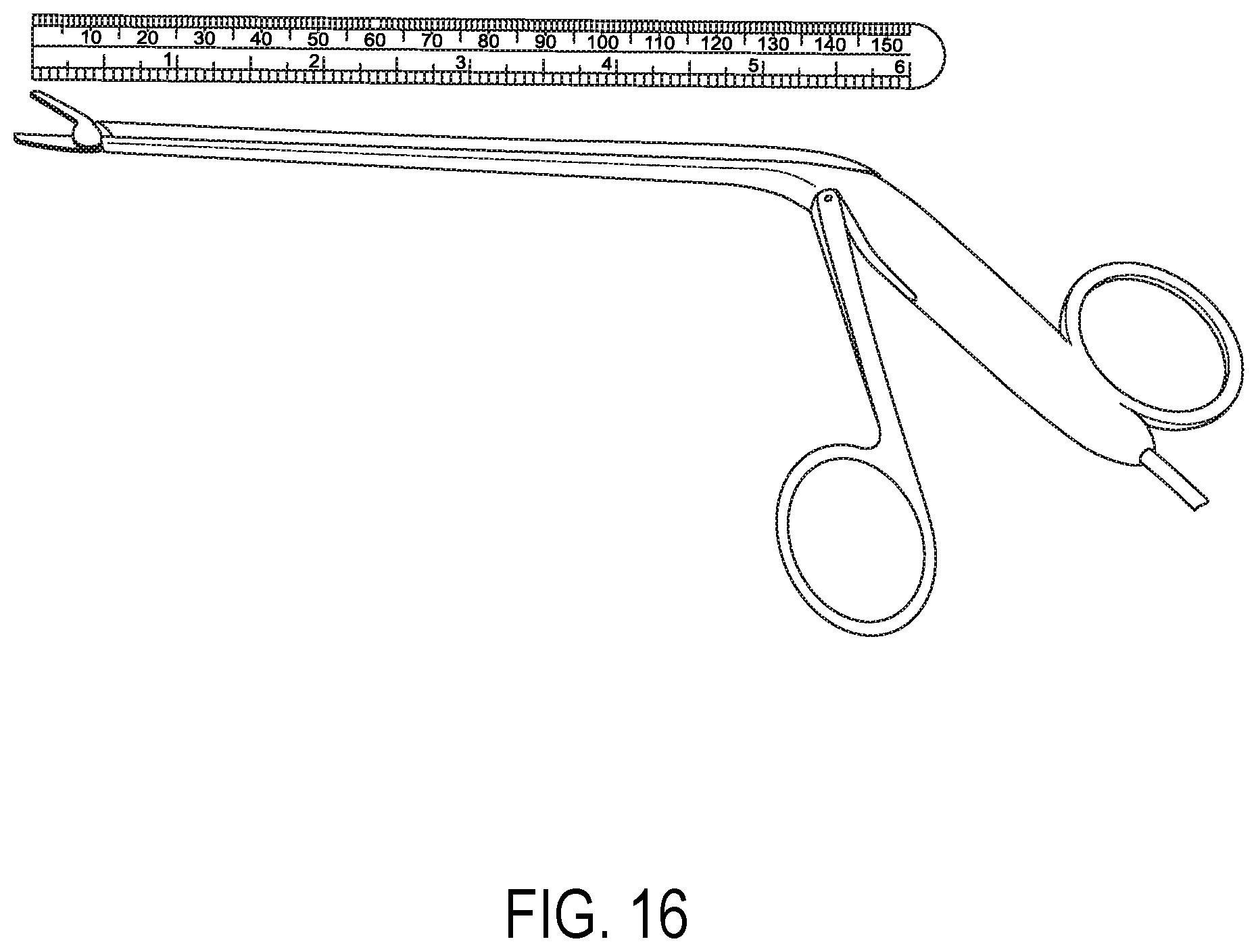
D00015
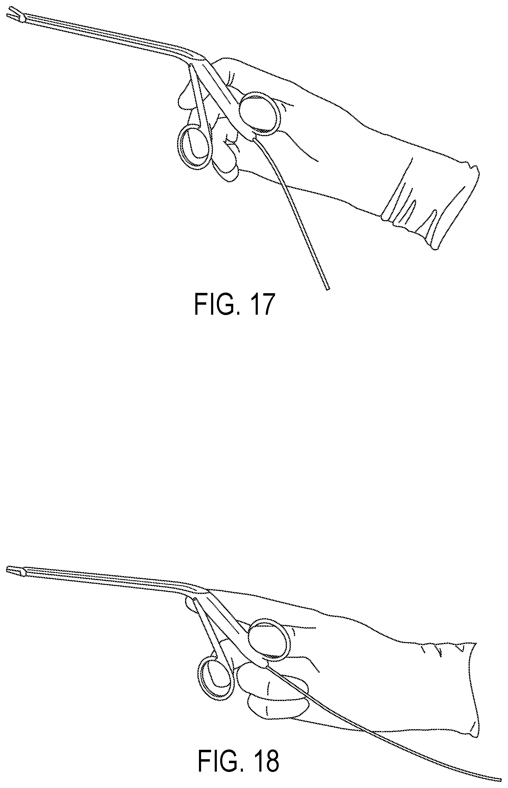
D00016

D00017

D00018

D00019

D00020
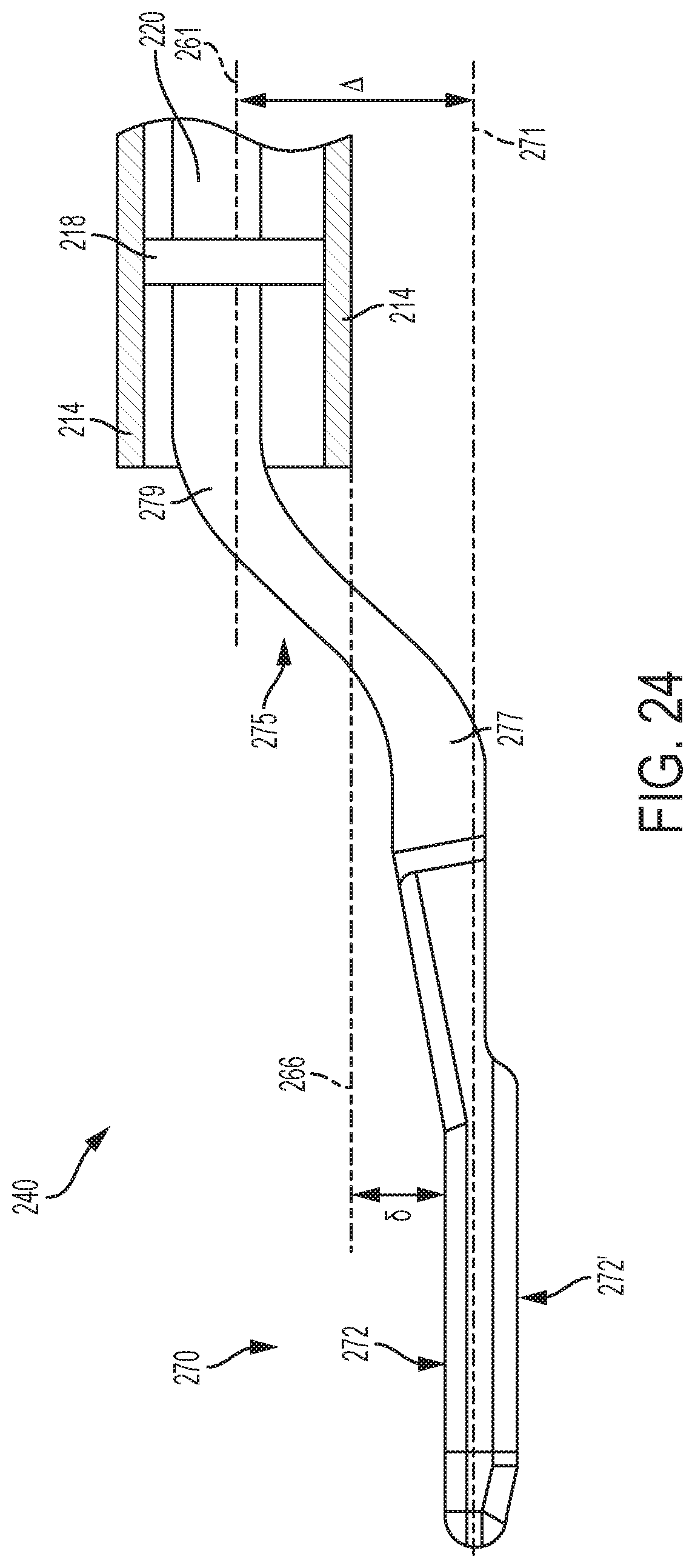
D00021

D00022

D00023

D00024
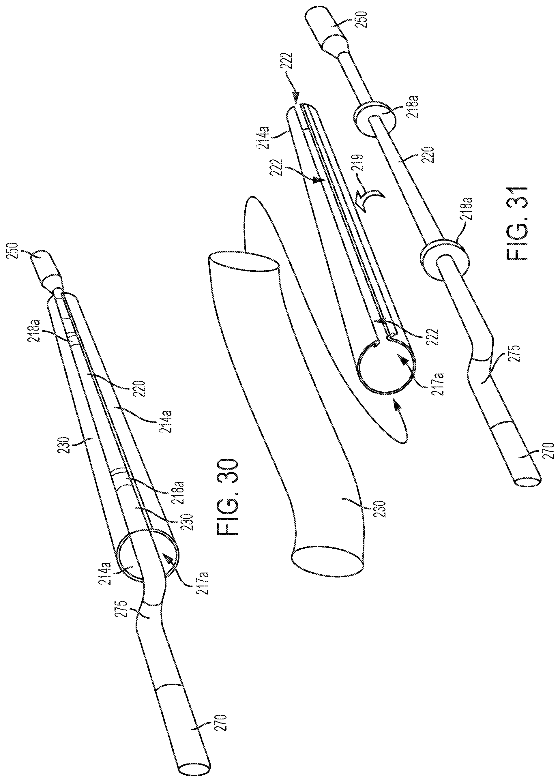
D00025
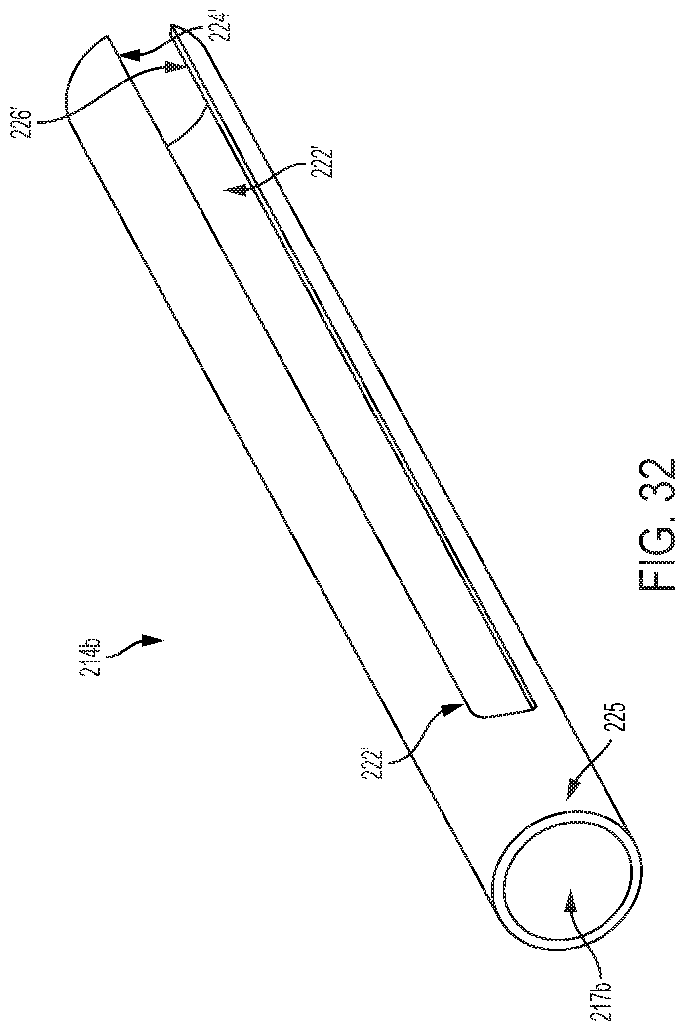
D00026
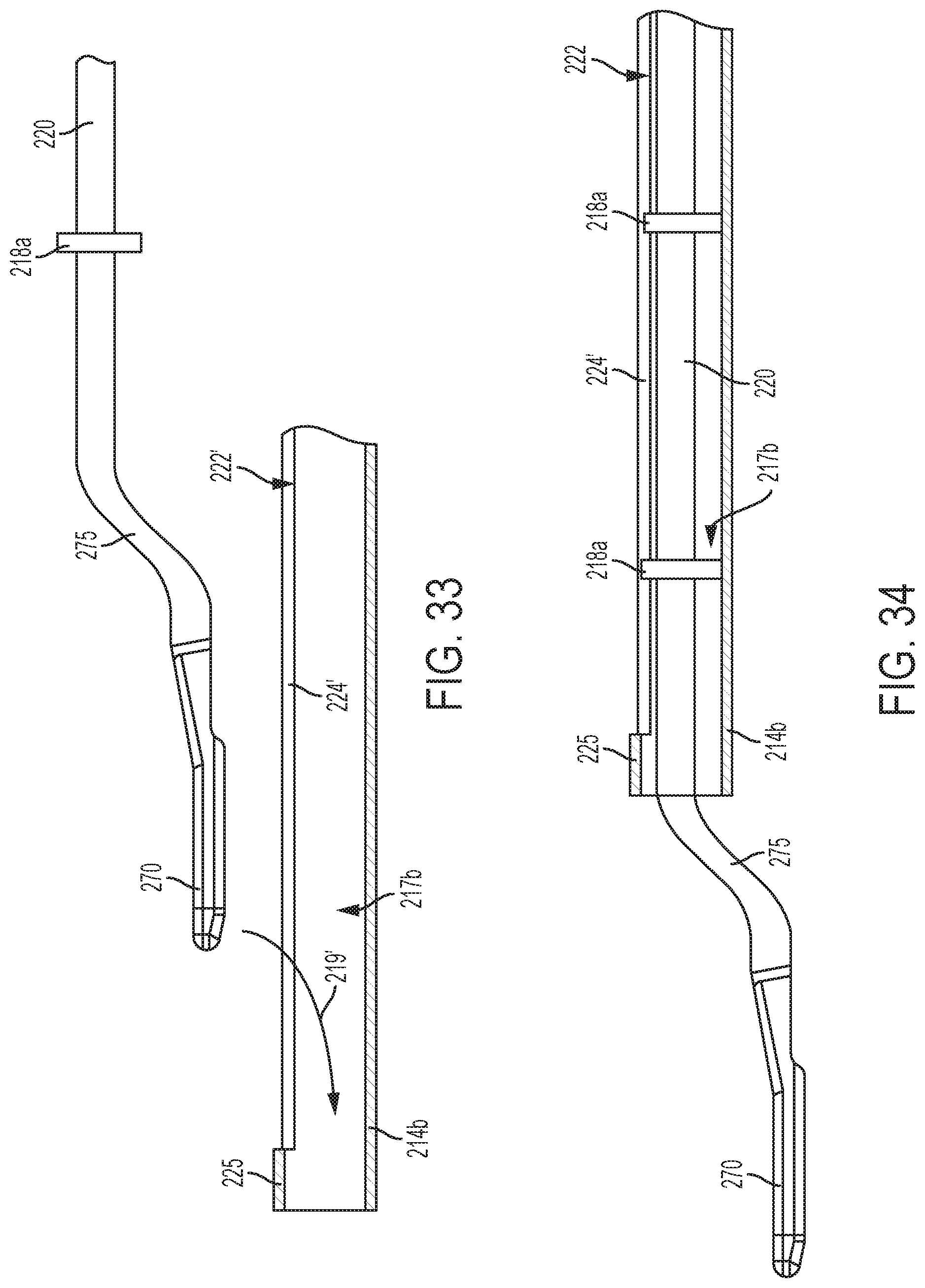
D00027
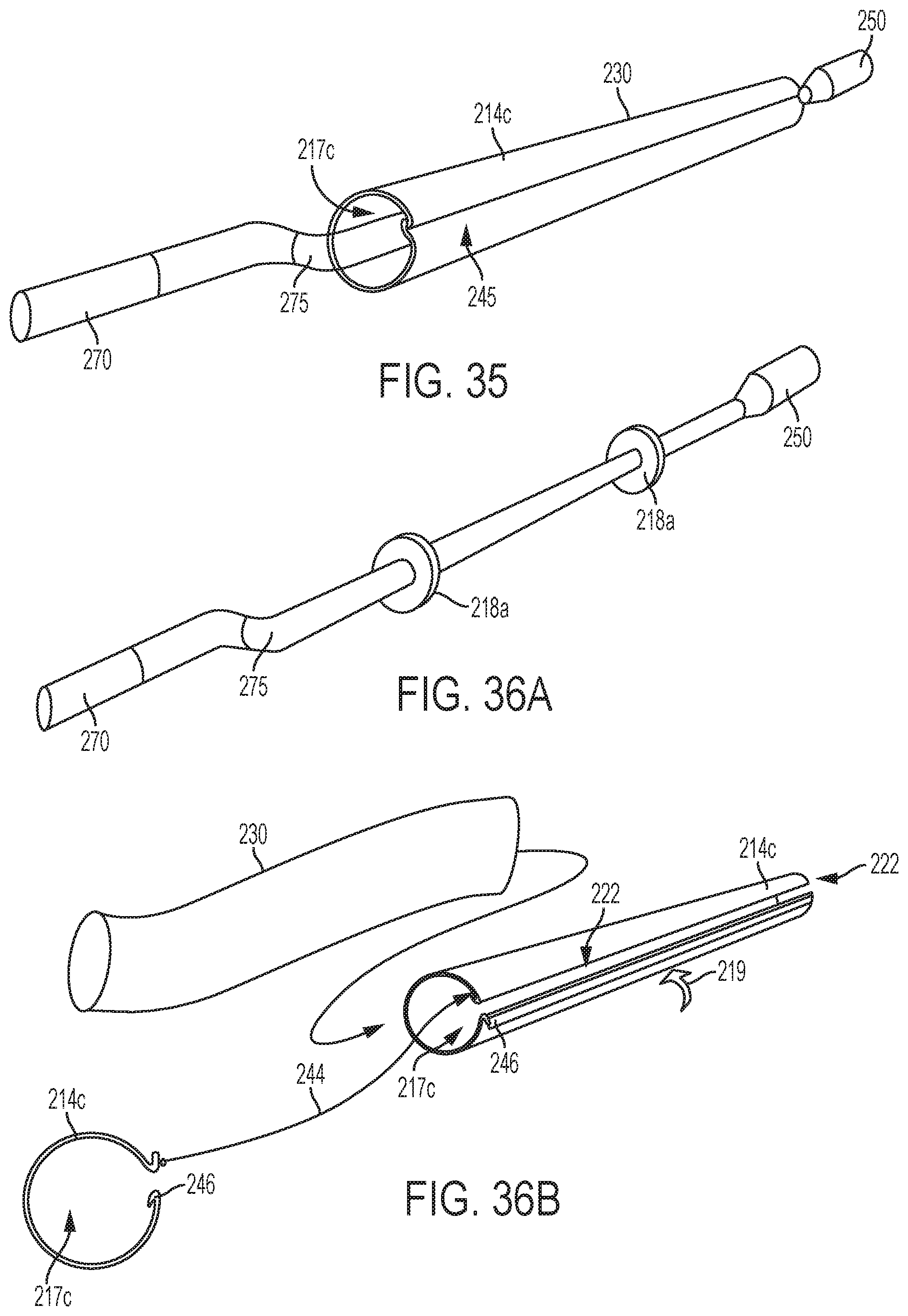
D00028

D00029

D00030

D00031

D00032
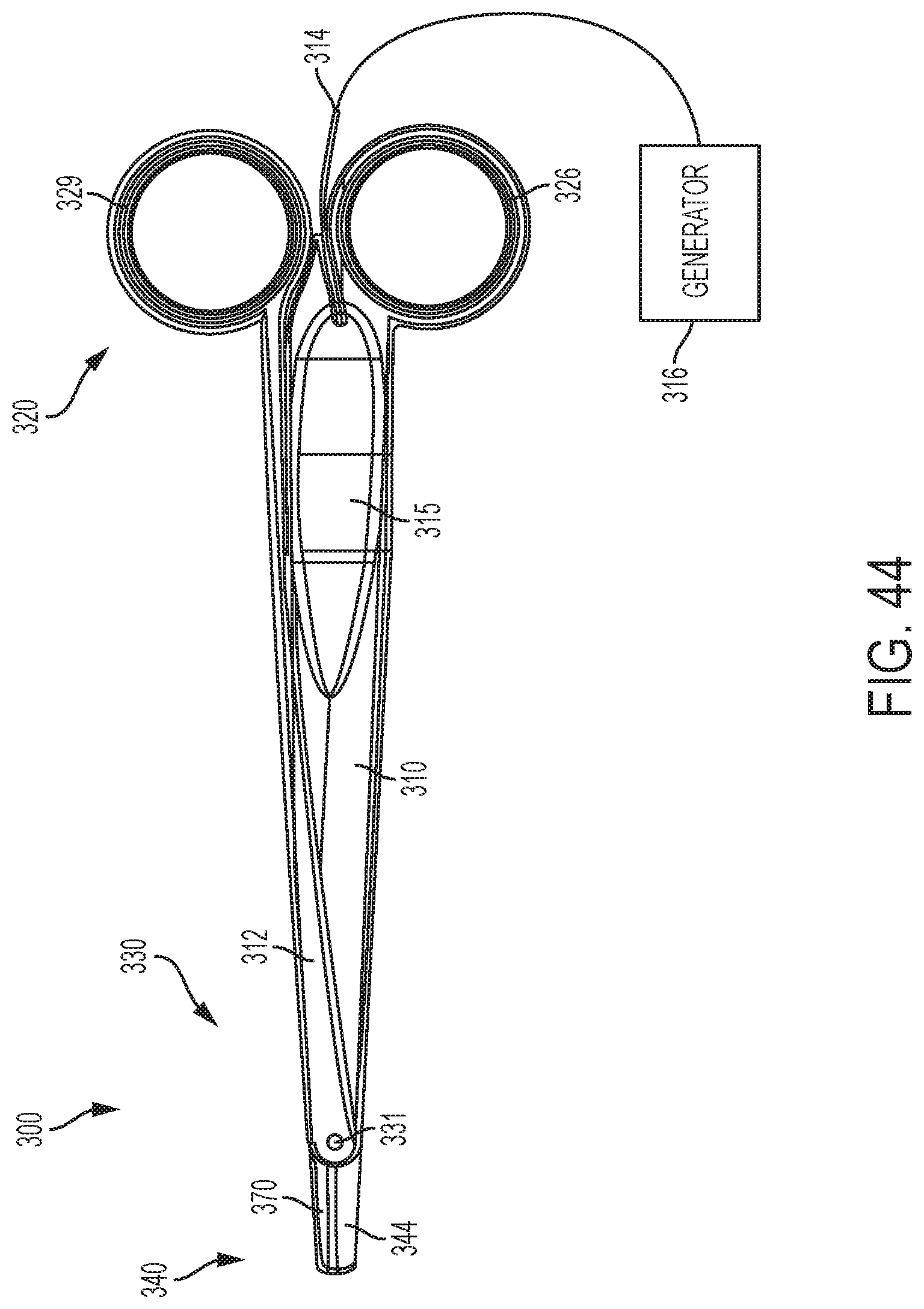
D00033

D00034
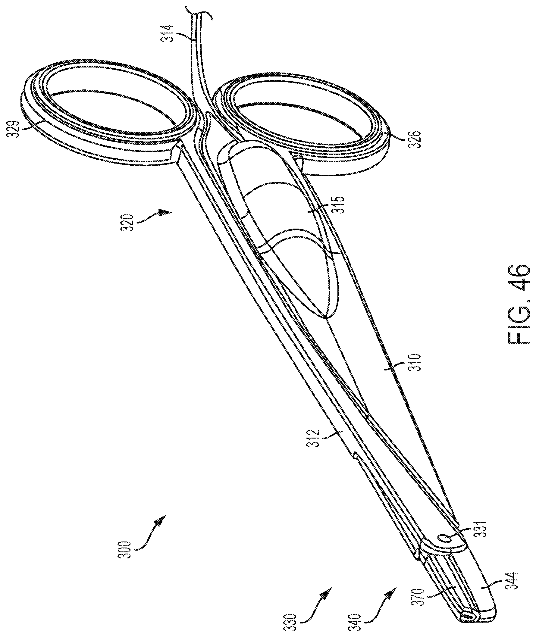
D00035

D00036

D00037
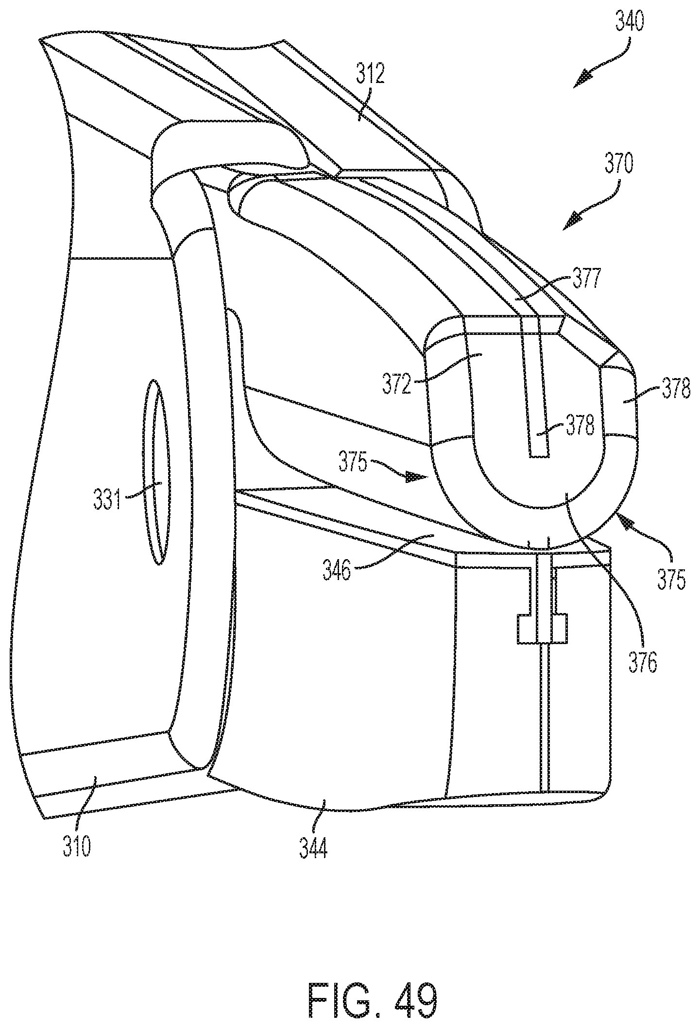
D00038

D00039
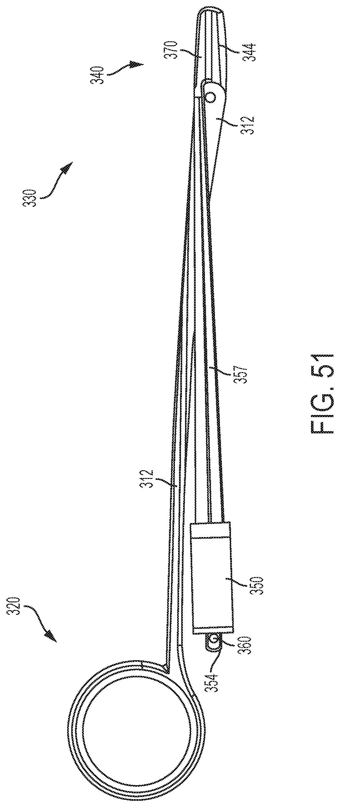
D00040

D00041

D00042
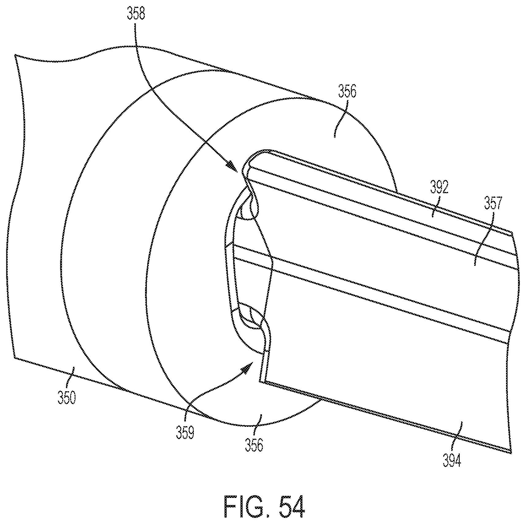
D00043
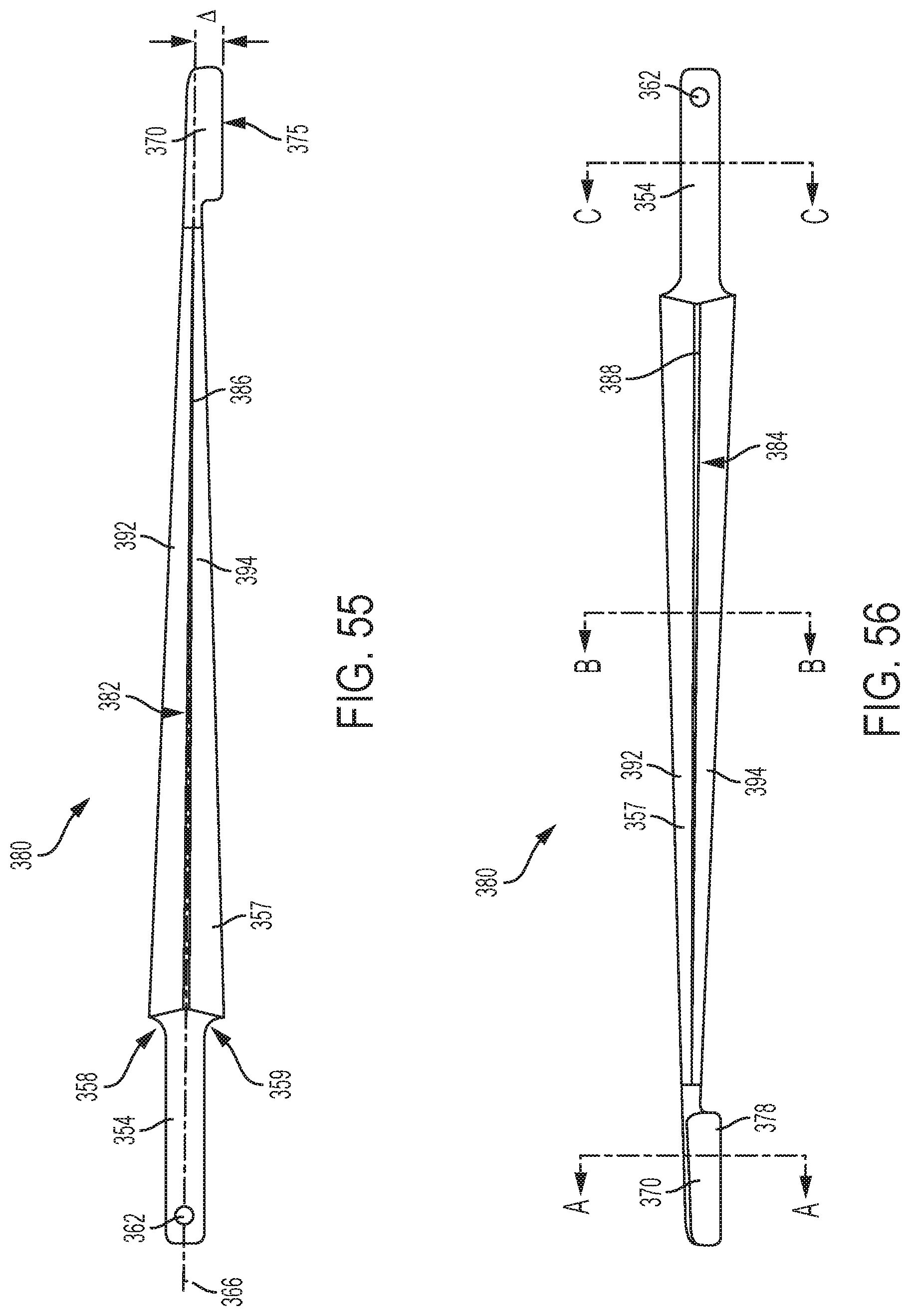
D00044
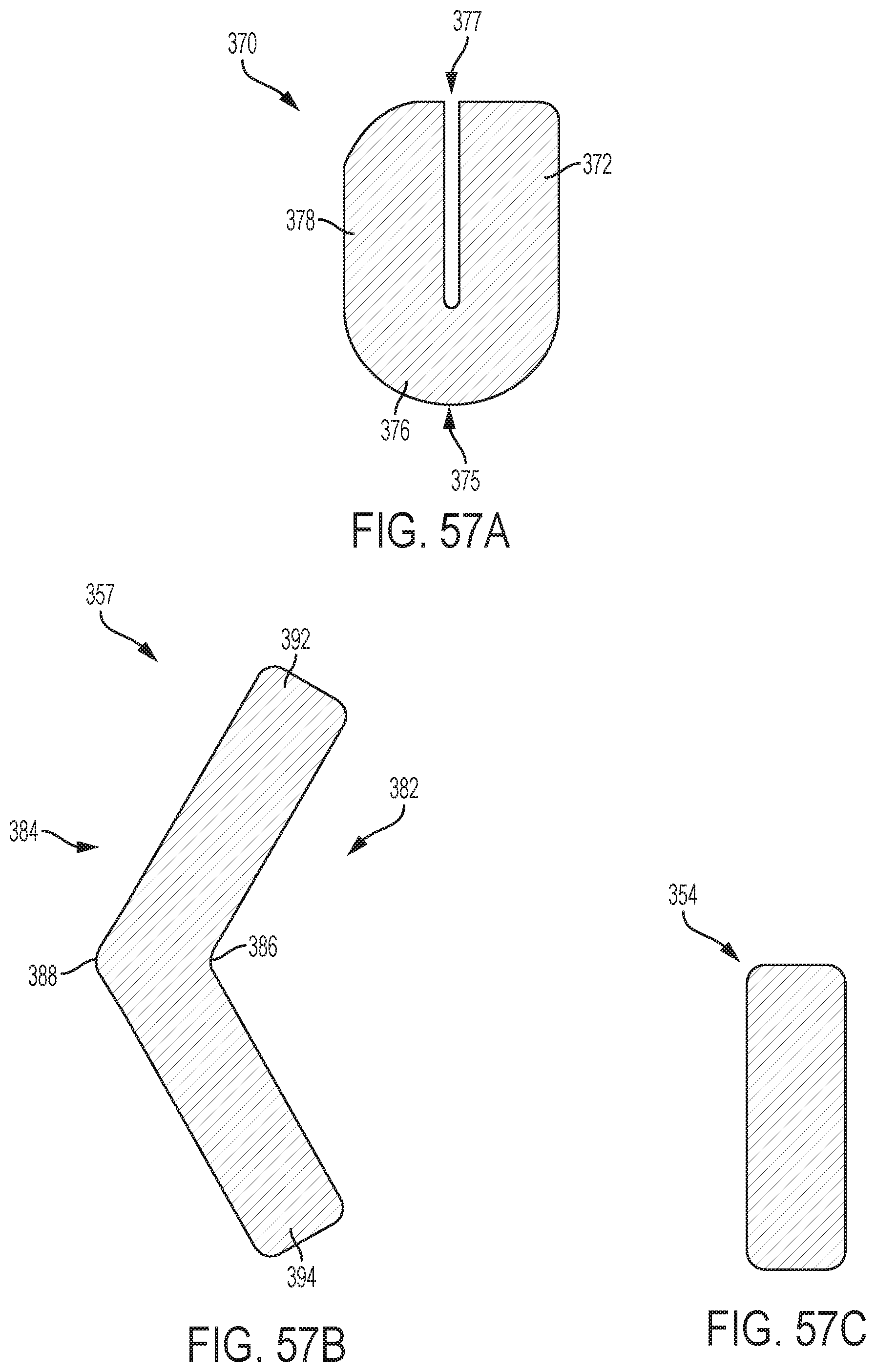
XML
uspto.report is an independent third-party trademark research tool that is not affiliated, endorsed, or sponsored by the United States Patent and Trademark Office (USPTO) or any other governmental organization. The information provided by uspto.report is based on publicly available data at the time of writing and is intended for informational purposes only.
While we strive to provide accurate and up-to-date information, we do not guarantee the accuracy, completeness, reliability, or suitability of the information displayed on this site. The use of this site is at your own risk. Any reliance you place on such information is therefore strictly at your own risk.
All official trademark data, including owner information, should be verified by visiting the official USPTO website at www.uspto.gov. This site is not intended to replace professional legal advice and should not be used as a substitute for consulting with a legal professional who is knowledgeable about trademark law.