Heat exchanger with improved flow
Andersson November 17, 2
U.S. patent number 10,837,717 [Application Number 15/103,242] was granted by the patent office on 2020-11-17 for heat exchanger with improved flow. This patent grant is currently assigned to SWEP International AB. The grantee listed for this patent is SWEP International AB. Invention is credited to Sven Andersson.

| United States Patent | 10,837,717 |
| Andersson | November 17, 2020 |
Heat exchanger with improved flow
Abstract
A heat exchanger comprises a number of identical heat exchanger plates stacked in a stack. Every other heat exchanger plate is turned 180 degrees in its plane relative to its neighboring plates, and each heat exchanger plate comprises at least four port openings and a herringbone pattern comprising pressed ridges and grooves. The ridges and grooves are adapted to keep the plates on a distance from one another under formation of flow channels, wherein areas around the port openings are arranged on different levels, such that selective flow from the port openings to the flow channels is achieved. Dents are arranged in the ridges and grooves in the vicinity of any of the port openings, the dents being arranged to increase the flow resistance to promote a more even flow distribution in the flow channel.
| Inventors: | Andersson; Sven (Hassleholm, SE) | ||||||||||
|---|---|---|---|---|---|---|---|---|---|---|---|
| Applicant: |
|
||||||||||
| Assignee: | SWEP International AB
(Landskrona, SE) |
||||||||||
| Family ID: | 52003755 | ||||||||||
| Appl. No.: | 15/103,242 | ||||||||||
| Filed: | November 28, 2014 | ||||||||||
| PCT Filed: | November 28, 2014 | ||||||||||
| PCT No.: | PCT/EP2014/075956 | ||||||||||
| 371(c)(1),(2),(4) Date: | June 09, 2016 | ||||||||||
| PCT Pub. No.: | WO2015/086343 | ||||||||||
| PCT Pub. Date: | June 18, 2015 |
Prior Publication Data
| Document Identifier | Publication Date | |
|---|---|---|
| US 20160313071 A1 | Oct 27, 2016 | |
Foreign Application Priority Data
| Dec 10, 2013 [SE] | 1351472 | |||
| Current U.S. Class: | 1/1 |
| Current CPC Class: | F28F 3/086 (20130101); F28F 13/08 (20130101); F28D 9/005 (20130101); F28F 3/042 (20130101); F28D 9/0025 (20130101); F28F 13/02 (20130101); F28D 9/0043 (20130101); F28F 9/026 (20130101); F28F 3/02 (20130101); F28F 3/10 (20130101); F28F 3/046 (20130101); F28D 9/0031 (20130101); F28D 9/0037 (20130101); F28D 1/0308 (20130101); F28F 3/08 (20130101); F28F 3/083 (20130101); F28F 13/06 (20130101); F28F 3/044 (20130101); F28F 3/04 (20130101); F28F 13/12 (20130101); F28F 2250/10 (20130101); F28F 2275/04 (20130101) |
| Current International Class: | F28F 3/04 (20060101); F28F 9/02 (20060101); F28F 13/08 (20060101); F28D 9/00 (20060101); F28F 3/10 (20060101); F28F 13/02 (20060101); F28F 13/06 (20060101); F28F 3/08 (20060101); F28F 13/12 (20060101); F28F 3/02 (20060101); F28D 1/03 (20060101) |
| Field of Search: | ;165/167,166 |
References Cited [Referenced By]
U.S. Patent Documents
| 3532161 | October 1970 | Loebel |
| 3661203 | May 1972 | Mesher |
| 3783090 | January 1974 | Andersson et al. |
| 3792730 | February 1974 | Andersson |
| 3817324 | June 1974 | Andersson |
| 3931854 | January 1976 | Ivakhnenko |
| 4781248 | November 1988 | Pfeiffer |
| 4915165 | April 1990 | Dahlgren |
| 4966227 | October 1990 | Andersson |
| 4987955 | January 1991 | Bergqvist |
| 5398751 | March 1995 | Blomgren |
| 5531269 | July 1996 | Dahlgren |
| 5727620 | March 1998 | Schaufele |
| 5971065 | October 1999 | Bertilson |
| 6394178 | May 2002 | Yoshida |
| 7213635 | May 2007 | Persson |
| 8109326 | February 2012 | Larsson |
| 8387248 | March 2013 | Rolt |
| 8746329 | June 2014 | Blomgren |
| 9217608 | December 2015 | Krantz |
| 9400142 | July 2016 | Holm |
| 9448013 | September 2016 | Ito |
| 9518782 | December 2016 | Blomgren |
| 2001/0030043 | October 2001 | Gleisle |
| 2004/0206488 | October 2004 | Ikuta |
| 2005/0039898 | February 2005 | Wand |
| 2006/0162915 | July 2006 | Matsuzaki |
| 2007/0000654 | January 2007 | Matsuzaki |
| 2007/0107890 | May 2007 | Geskes |
| 2008/0029257 | February 2008 | Nilsson |
| 2008/0196874 | August 2008 | Bertilsson |
| 2008/0210414 | September 2008 | Blomgren |
| 2008/0283231 | November 2008 | Horte |
| 2009/0133861 | May 2009 | Kim |
| 2009/0178793 | July 2009 | Larsson |
| 2010/0276125 | November 2010 | Krantz |
| 2011/0139419 | June 2011 | Blomgren |
| 2011/0240273 | October 2011 | Blomgren |
| 2012/0031598 | February 2012 | Han |
| 2012/0118546 | May 2012 | Andersson |
| 2012/0125578 | May 2012 | Persson |
| 2012/0325434 | December 2012 | Blomgren |
| 2013/0113126 | May 2013 | Mockry |
| 2013/0126135 | May 2013 | Romlund |
| 2013/0180699 | July 2013 | Dahlberg |
| 2013/0192291 | August 2013 | Ito |
| 2013/0327513 | December 2013 | Franz |
| 2014/0026577 | January 2014 | Reinke |
| 2014/0034276 | January 2014 | Persson |
| 2015/0184954 | July 2015 | Bertilsson |
| 2015/0276319 | October 2015 | Hedberg |
| 2016/0187076 | June 2016 | Blomgren |
| 2016/0245591 | August 2016 | Masgrau |
| 2016/0250703 | September 2016 | Bornegard |
| 2016/0313066 | October 2016 | Andersson |
| 2017/0016680 | January 2017 | Zhang |
| 2018/0106558 | April 2018 | Buckrell |
| 2019/0360768 | November 2019 | Dahlberg |
| 2470557 | Jun 2003 | CA | |||
| 2450739 | Apr 1976 | DE | |||
| 9408904 | Aug 1994 | DE | |||
| 102012022046 | May 2014 | DE | |||
| 0204880 | Dec 1986 | EP | |||
| 0252275 | Jan 1988 | EP | |||
| 2267391 | Dec 2010 | EP | |||
| 2420791 | Feb 2012 | EP | |||
| 3093602 | Nov 2016 | EP | |||
| S56-039294 | Sep 1982 | JP | |||
| 08219677 | Aug 1996 | JP | |||
| 2011-517764 | Jun 2011 | JP | |||
| WO 2013080256 | Jun 2013 | JP | |||
| WO-9300563 | Jan 1993 | WO | |||
| WO-2009128750 | Oct 2009 | WO | |||
| WO-2009154543 | Dec 2009 | WO | |||
| WO-2010016792 | Feb 2010 | WO | |||
| WO-2010069873 | Jun 2010 | WO | |||
| WO 2010069873 | Jun 2010 | WO | |||
| WO-2012004100 | Jan 2012 | WO | |||
Other References
|
WO 2013080256 A1 Machine Translation English--Retrieved Jun. 2017. cited by examiner . WO-2010069873-A1 (Year: 2010). cited by examiner . International Search Report for No. PCT/EP2014/075956, dated Feb. 4, 2015 (3 pages). cited by applicant . English Translation of Office Action for Japanese Patent Application No. 2016-536119, dated Sep. 4, 2018. cited by applicant. |
Primary Examiner: Tran; Len
Assistant Examiner: Hopkins; Jenna M
Attorney, Agent or Firm: Merchant & Gould P.C.
Claims
The invention claimed is:
1. A heat exchanger comprising: (a) a number of identical heat exchanger plates stacked in a stack, wherein every other heat exchanger plate is turned 180 degrees in its plane relative to neighboring heat exchanger plates, and wherein each heat exchanger plate comprises at least four port openings and a herringbone pattern comprising pressed ridges and grooves; (b) said ridges and grooves of the herringbone pattern providing contact points between neighboring heat exchanger plates and keeping the heat exchanger plates a distance from one another and providing flow channels, wherein said flow channels comprise a first flow channel and a second flow channel, wherein areas around the port openings are arranged on different levels, such that selective flow from the port openings to the flow channels is achieved; (c) said port openings comprising a first inlet port opening open to said first flow channel and closed to said second flow channel, and a second inlet port opening closed to said first flow channel and open to said second flow channel; and (d) wherein, seen from a frontal side of the heat exchanger plates, dents are arranged in the grooves of the herringbone pattern of the heat exchanger plates immediately adjacent said first inlet port opening, and dents are not arranged in the grooves of the herringbone pattern of the heat exchanger plates immediately adjacent said second inlet port opening, said dents in the grooves of the herringbone pattern being arranged to increase a flow resistance for fluid traveling in said first flow channel such that the fluid is directed toward a side of the heat exchanger plate where the second inlet port opening is placed to thereby promote a more even flow distribution in said flow channels, wherein said dents in the grooves of the herringbone pattern are placed such that said dents in the grooves of the herringbone pattern do not form contact points with the neighboring heat exchanger plates.
2. The heat exchanger of claim 1, wherein the dents are provided around two neighboring port openings, and wherein the dents in the areas of one of said neighboring port openings are placed in the ridges, and the dents in the areas of the other of the two neighboring port openings are placed in the grooves.
3. The heat exchanger of claim 1, wherein the heat exchanger plates in the stack are joined by brazing.
4. A heat exchanger comprising: (a) a number of identical heat exchanger plates stacked in a stack, wherein every other heat exchanger plate is turned 180 degrees in its plane relative to neighboring heat exchanger plates, and wherein each heat exchanger plate comprises at least four port openings and a herringbone pattern comprising pressed ridges and grooves; (b) said ridges and grooves of the herringbone pattern providing contact points between neighboring heat exchanger plates and keeping the heat exchanger plates a distance from one another and providing flow channels, wherein the said flow channels comprise a first flow channel and a second flow channel, wherein areas around the port openings are arranged on different levels, such that selective flow from the port openings to the flow channels is achieved; (c) said port openings comprising a first inlet port opening open to said first flow channel and closed to said second flow channel, and a second inlet port opening closed to said first flow channel and open to said second flow channel; and (d) wherein, seen from a frontal side of the heat exchanger plates, dents are arranged in the ridges of the herringbone pattern of the heat exchanger plates immediately adjacent said second inlet port opening, and dents are not arranged in the ridges of the herringbone pattern of the heat exchanger plates immediately adjacent said first inlet port opening, said dents in the ridges of the herringbone pattern being arranged to decrease a flow resistance for fluid traveling in said second flow channels to thereby promote a more even flow distribution in said flow channels, wherein said dents in the ridges of the herringbone pattern in the heat exchanger plates are placed such that said dents in the ridges of the herringbone pattern do not form contact points with the neighboring heat exchanger plates.
Description
This application is a National Stage Application of PCT/EP2014/075956, filed 28 Nov. 2014, which claims benefit of application Ser. No. 1351472-4, filed 10 Dec. 2013 in Sweden, and which applications are incorporated herein by reference. To the extent appropriate, a claim of priority is made to each of the above disclosed applications.
FIELD OF THE INVENTION
The present invention relates to a heat exchanger comprising a number of identical heat exchanger plates stacked in a stack, wherein every other heat exchanger plate is turned 180 degrees in its plane relative to its neighboring plates, and wherein each heat exchanger plate comprises at least four port openings and a herringbone pattern comprising pressed ridges and grooves, said ridges and grooves being adapted to keep the plates on a distance from one another under formation of flow channels, wherein areas around the port openings are arranged on different levels, such that selective flow from the port openings to the flow channels is achieved.
PRIOR ART
The most common type of heat exchanger is the type of heat exchangers comprising a number of identical heat exchanger plates, each comprising port openings, the surrounding areas of which being located at different heights to arrange for selective fluid communication into flow channels arranged by interaction between pressed patterns of ridges and grooves of neighboring heat exchanger plates.
As well known by persons skilled in the art of heat exchangers, heat exchangers of the type described above have one small drawback compared to heat exchangers made from non-identical plates, namely that inlet and outlet port openings for one of the fluids are placed on one side of the axis of the heat exchanger, whereas the openings for the other fluid are place placed on the other side of the axis.
This leads to a slight maldistribution of the fluids to exchange heat, since there is a shorter way (and hence less resistance) for the fluids to travel in a straight line from port opening to port opening. A majority of the flow of each fluid will hence flow shifted towards one side of the heat exchanger, compared to the axis of the heat exchanger. Obviously, the optimum distribution would be an even flow of both fluids in the flow channels arranged by the neighboring plates.
The maldistribution problem is even more pronounced for heat exchangers having a large width as compared to its length--an old "rule of thumb" indicates that the length preferably should be 1.7 times the width in order to get an acceptable heat exchanger efficiency.
In US 2007/0107890, the problem of sideways maldistribution is addressed by providing contact points between neighbouring plates such that the flow of fluid therein has a larger flow resistance in the sideways direction as compared to the linear direction of the flow. Supposedly, this will force the fluid to flow in a more positive direction and hence reduce maldistribution problems.
EP 2 420 791 discloses a radiator type plate heat exchanger for exchanging heat between a fluid flowing in a flow channel and ambient air. In order to avoid stagnant flow behind port openings, flow guide structures provided on sides of the port opening are arranged to decrease the flow resistance, such that a stagnant area around the port opening is avoided. Sideways maldistribution of the flow is not mentioned, and the design of this document also does not affect sideways maldistribution, since both sides of the port openings are provided with identical flow guide structures.
The present invention aims to improve the flow distribution in a heat exchanger made from identical heat exchanger plates.
SUMMARY OF THE INVENTION
The present invention solves the above and other problems by providing a heat exchanger of the type mentioned above, with the added features of dents arranged in the ridges and grooves in the vicinity of any of the port openings. The dents are arranged to increase the flow resistance to promote a more even flow distribution in said flow channel.
In one embodiment of the invention, said dents are placed such that contact points between said ridges and grooves of the neighbouring plates in the stack are not affected by said dents. This increases the strength of the heat exchanger.
If not enough effect on the flow distribution is achieved by the arrangement above, dents may be provided around two neighboring port openings, wherein the dents in the vicinity of one of said neighboring port openings are placed in the ridges, and the dents in the vicinity of the other of the two neighboring port openings are placed in the grooves.
In order to achieve a cost efficient heat exchanger, the heat exchanger plates in the stack may be joined by brazing.
BRIEF DESCRIPTION IF THE DRAWINGS
Hereinafter, the invention will be described with reference to the appended drawings, wherein:
FIG. 1 is an exploded perspective view of a heat exchanger comprising six identical heat exchanger plates;
FIG. 2 is a perspective view showing one of the heat exchanger plates in FIG. 1; and
FIG. 3 is a perspective view showing the area denoted B in FIG. 2;
DESCRIPTION OF EMBODIMENTS
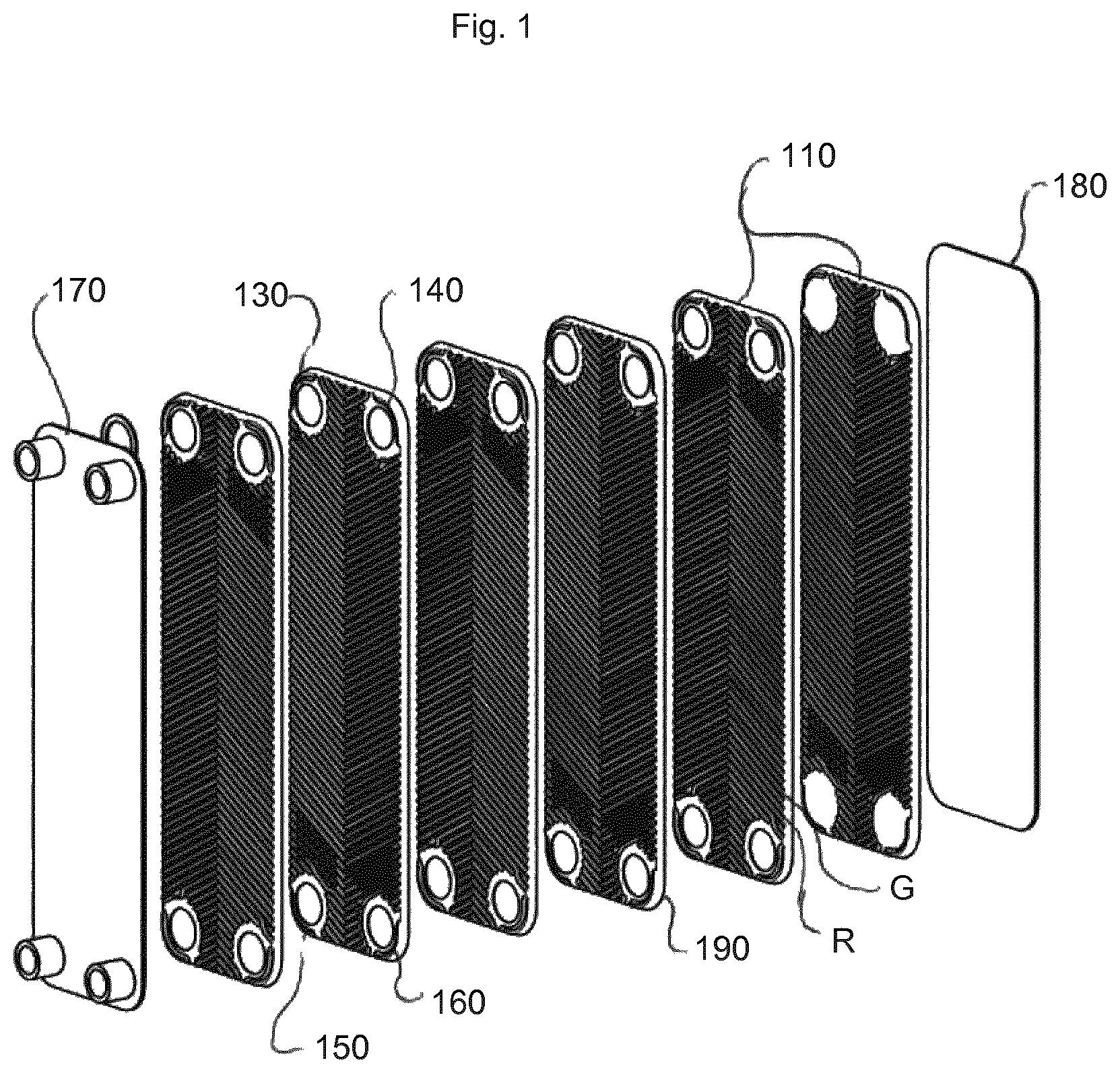
With reference to FIG. 1, a heat exchanger 100 according to the present invention comprises a number of identical heat exchanger plates 110, each comprising four port openings 130, 140, 150 and 160, the openings 130, 150 being inlet openings and outlet openings, respectively, for a first fluid, the openings 160, 140 being inlet openings and outlet openings, respectively, for a second fluid intended to exchange heat with the first fluid.
The plates also comprise ridges R and grooves G arranged in a herringbone pattern and adapted to keep the plates on a distance from one another under formation of flow channels. Areas around the port openings are arranged on different heights in order to allow for selective fluid flow to the flow channels. The areas around the port openings 130 and 150 are provided on the same height, e.g. the height of the ridges R, whereas the areas around the port openings 140, 150 are provided on another height, e.g. the height of the grooves G.
Two neighboring plates are always mutually turned by 180 degrees in the plane, i.e. such that port openings 130 and 160 will neighbor one another, and port openings 150 and 140 will neighbor one another. As mentioned earlier, the areas surrounding the ports are arranged on different heights, meaning that one pair of port openings placed on one side of the axis of the plates will allow fluid flow into the flow channels arranged by the neighboring plates, whereas the other pair of port openings will be closed, i.e. not allow fluid flow into the same channel. However, the same pair of port openings will be in fluid communication with the flow channels arranged by the next neighboring heat exchanger plate.
Moreover, the heat exchanger plates are provided with a skirt 190 extending around the periphery of the plates 110. The skirts of neighboring plates are arranged to seal the flow channels, such that no leakage to and from the flow channels is allowed.
Finally, end plates 170, 180 are arranged on the outside of the stack of heat exchanger plates. The purpose of the end plates is to increase the strength, i.e. pressure capability of the heat exchanger. Should the pressure requirements be low, the end plates could be omitted.
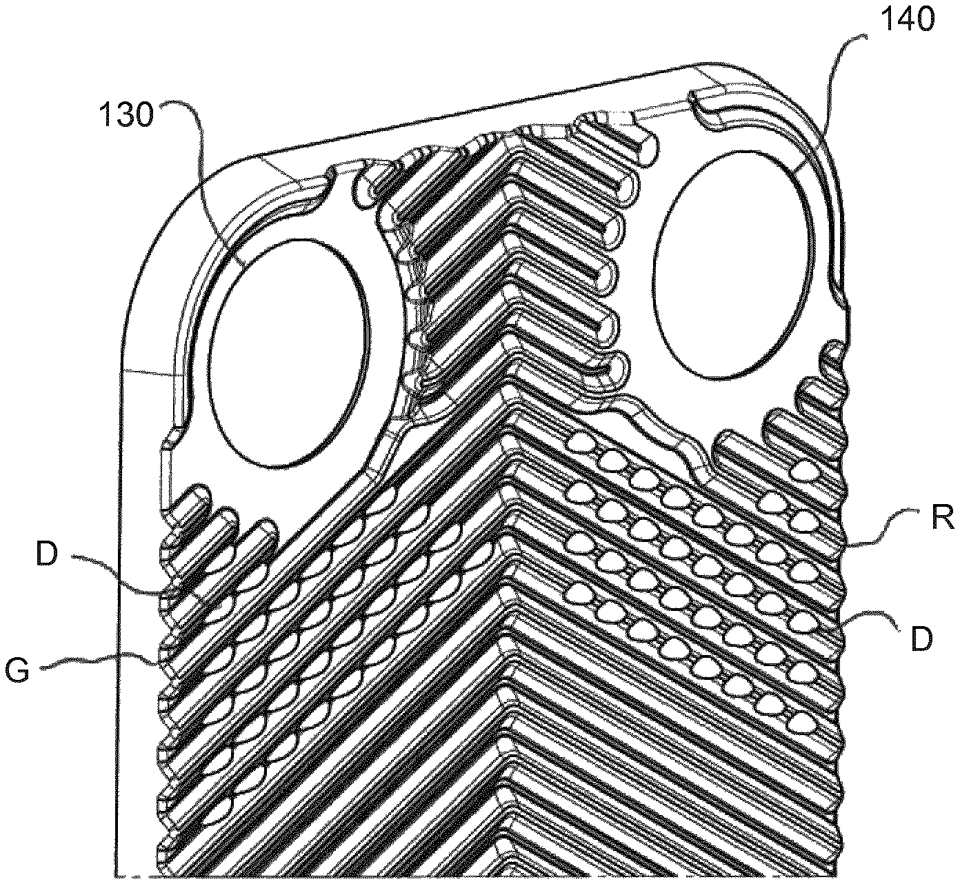
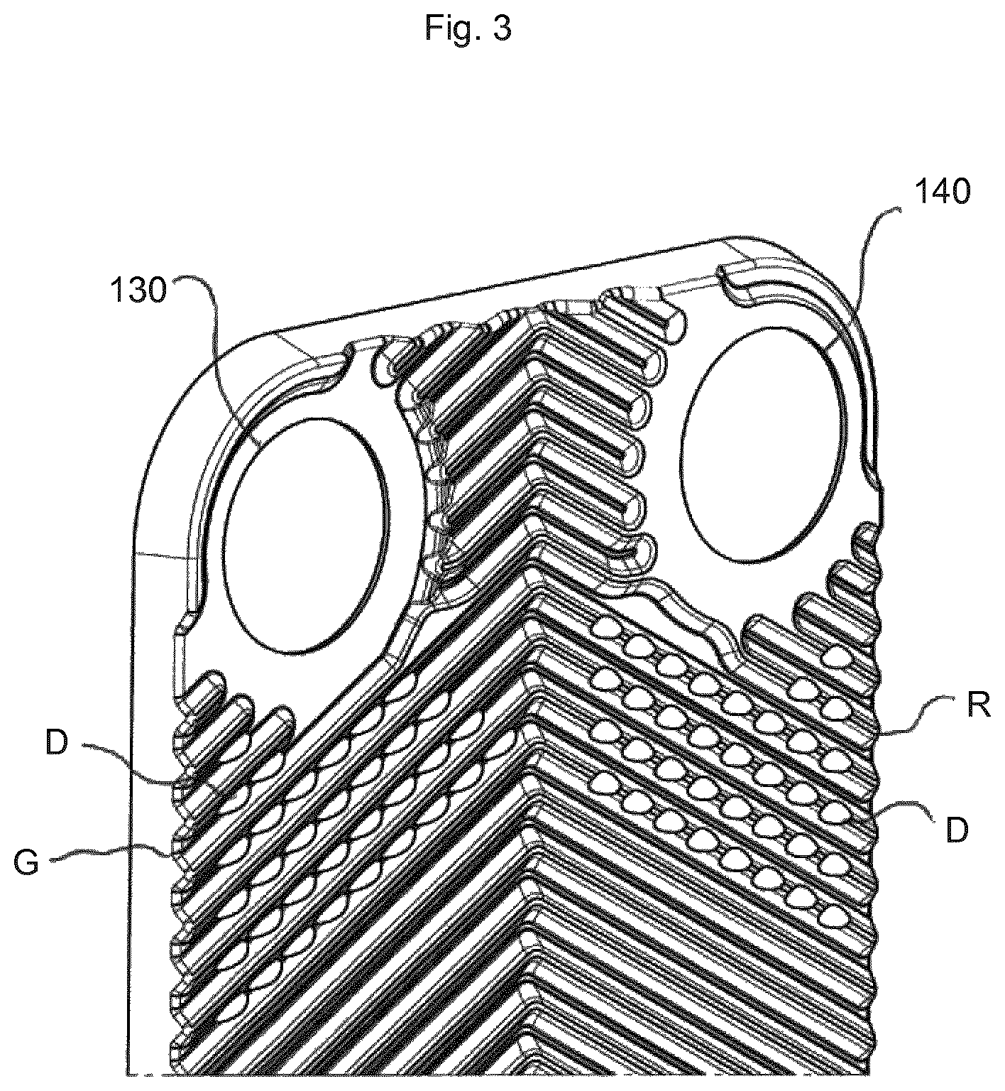
FIG. 2 shows one of the heat exchanger plates 110; in this figure, some irregularities of the herringbone pattern comprising the ridges and grooves R and G, respectively, are shown in the vicinity of the port openings 130 and 140. In FIG. 3, this area (denoted by B in FIG. 2), is shown in greater detail. In the vicinity of the port openings 150 and 160, the herringbone pattern is not irregular.
As can be seen in FIG. 3, the herringbone pattern comprising ridges R and grooves G is interrupted by dents D; in the vicinity of the port opening 130, the dents D are arranged in the grooves G, whereas in the vicinity of the port opening 140, the dents D are placed in the ridges R.
As mentioned above, the heat exchanger plates are stacked onto one another, wherein each other plate is turned 180 degrees relative to its neighboring plates. If one imagines a plate 110 being placed on top of the plate partly shown in FIG. 3, and turned 180 as compared to this plate, it is clear that the port opening 130 will be open to the flow channel delimited by these two plates, whereas the port opening 140 will be closed.
The dents D in the grooves G in the vicinity of the port 130 will decrease the flow volume, and hence increase the pressure drop, in the vicinity of the port opening 130, whereas the dents D in the ridges R in the vicinity of the port opening 140 will increase the flow volume, and hence decrease the pressure drop for a fluid travelling the flow channel. Considering the port opening 130 is an inlet opening, the fluid will hence be directed towards the side of the axis of the heat exchanger plate where the port opening 140 is placed.
If an identical plate is placed below the plate shown in FIG. 3, the port opening 140 will be open for fluid low into the flow channel delimited by these two plates, and the flow will be directed (or rather urged) to a path on the side of the axis of the heat exchanger plate where the port opening 130 is placed. It is, however, rather unlikely that anyone would place two inlet ports next to one another.
However, due to the identical plates, the impact on the pressure drops, and hence flow distribution will be equal for the port openings 150, 160.
Above, the invention has been described with reference to one single embodiment, which results in a significant improvement in the flow distribution of a plate heat exchanger made from a stack of identical heat exchanger plates, wherein every other plate is turned 180 degrees in the plane as compared to its neighboring plates. In the shown embodiment, this is achieved by providing both the ridges and the grooves of the herringbone pattern holding the plates on a distance from one another by contacting point with dents D. It is, however, possible to achieve the same result by only providing e.g. the grooves G in the vicinity of the port opening 130 with dents, or only the ridges R in the vicinity of the port opening 140 with dents D.
It is also possible to provide the grooves G in the vicinity of both port openings 130 and 150 with dents and the ridges R in the vicinity of both port openings 140, 160 with dents.
The invention could be used both for brazed heat exchangers and for packed heat exchangers, i.e. heat exchangers where the sealing around edge portions and port openings is provided by gaskets.
* * * * *
D00000
D00001
D00002
D00003
XML
uspto.report is an independent third-party trademark research tool that is not affiliated, endorsed, or sponsored by the United States Patent and Trademark Office (USPTO) or any other governmental organization. The information provided by uspto.report is based on publicly available data at the time of writing and is intended for informational purposes only.
While we strive to provide accurate and up-to-date information, we do not guarantee the accuracy, completeness, reliability, or suitability of the information displayed on this site. The use of this site is at your own risk. Any reliance you place on such information is therefore strictly at your own risk.
All official trademark data, including owner information, should be verified by visiting the official USPTO website at www.uspto.gov. This site is not intended to replace professional legal advice and should not be used as a substitute for consulting with a legal professional who is knowledgeable about trademark law.