Means For Sensing Temperature
DAHLBERG; Tomas ; et al.
U.S. patent application number 16/470130 was filed with the patent office on 2019-11-28 for means for sensing temperature. The applicant listed for this patent is SWEP INTERNATIONAL AB. Invention is credited to Sven ANDERSSON, Tomas DAHLBERG.
| Application Number | 20190360768 16/470130 |
| Document ID | / |
| Family ID | 60702720 |
| Filed Date | 2019-11-28 |
| United States Patent Application | 20190360768 |
| Kind Code | A1 |
| DAHLBERG; Tomas ; et al. | November 28, 2019 |
MEANS FOR SENSING TEMPERATURE
Abstract
A brazed plate heat exchanger comprises a number of heat exchanger plates (100) provided with a pressed pattern comprising ridges (R) and grooves (G). The ridges and grooves of neighboring plates contact one another in order to keep the plates on a distance from one another under formation of interplate flow channels for media to exchange heat when the heat exchanger plates are placed in a stack to form the heat exchanger. Means (120a, 120b) are provided for allowing temperature measurement of a fluid present in a second flow channel counted from an end of the stack of heat exchanger plates (100).
| Inventors: | DAHLBERG; Tomas; (Helsingborg, SE) ; ANDERSSON; Sven; (Hassleholm, SE) | ||||||||||
| Applicant: |
|
||||||||||
|---|---|---|---|---|---|---|---|---|---|---|---|
| Family ID: | 60702720 | ||||||||||
| Appl. No.: | 16/470130 | ||||||||||
| Filed: | December 11, 2017 | ||||||||||
| PCT Filed: | December 11, 2017 | ||||||||||
| PCT NO: | PCT/EP2017/082228 | ||||||||||
| 371 Date: | June 14, 2019 |
| Current U.S. Class: | 1/1 |
| Current CPC Class: | F28F 27/00 20130101; F28F 3/046 20130101; F28D 9/005 20130101; G01K 13/02 20130101; F28F 3/044 20130101 |
| International Class: | F28F 27/00 20060101 F28F027/00; G01K 13/02 20060101 G01K013/02; F28D 9/00 20060101 F28D009/00; F28F 3/04 20060101 F28F003/04 |
Foreign Application Data
| Date | Code | Application Number |
|---|---|---|
| Dec 16, 2016 | SE | 1651666-8 |
Claims
1. A brazed plate heat exchanger comprising a number of heat exchanger plates provided with a pressed pattern comprising ridges (R) and grooves (G), said ridges and grooves of neighboring plates contacting one another in order to keep the plates on a distance from one another under formation of interplate flow channels for media to exchange heat when the heat exchanger plates are placed in a stack to form the heat exchanger, characterized by means for allowing temperature measurement of a fluid present in a second flow channel counted from an end of the stack of heat exchanger plates.
2. The brazed plate heat exchanger according to claim 1, wherein the means for allowing temperature measurement of the fluid in the second flow channel comprises plan portions arranged to abut one another and hence allow for heat transfer from the second flow channel to a temperature sensor.
3. The brazed plate heat exchanger according to claim 1, wherein the means for allowing temperature measurement of the fluid in the second flow channel comprises a recessed portion provided in an outer heat exchanger plate, said recessed portion being provided with a pressed pattern corresponding to a pressed pattern of the neighboring heat exchanger plate, such that the pressed pattern of the recessed portion and the neighbouring plate snugly fits one another and hence provides for a heat transfer from the second flow channel to a temperature sensor.
Description
TECHNICAL FIELD
[0001] The present invention relates to a brazed plate heat exchanger comprising a number of heat exchanger plates provided with a pressed pattern comprising ridges and grooves, said ridges and grooves of neighboring plates contacting one another in order to keep the plates on a distance from one another under formation of interplate flow channels for media to exchange heat when the heat exchanger plates are placed in a stack to form the heat exchanger.
BACKGROUND
[0002] Brazed plate heat exchangers are often used as evaporators and/or condensers in heating and cooling applications wherein a refrigerant is compressed, condensed and evaporated in order to utilize a low temperature source for evaporation and a high temperature source for the condensation.
[0003] In order to control such systems, it is common to use a controllable driving source for a compressor compressing gaseous refrigerant and a controllable expansion valve for controlling a pressure ratio between a high pressure side (where the refrigerant is condensed) and a low pressure side (where the refrigerant is evaporated). In order to get an as efficient process as possible, it is essential not to overheat the refrigerant vapor in the evaporator to a too large degree, but it is also crucial that all of the refrigerant is vaporized, since liquid phase refrigerant will ruin the compressor.
[0004] In order to enable an optimization of the system, it is crucial to be able to measure temperatures and pressure accurately.
[0005] In most applications, the refrigerant exchanges heat with a heat carrier, most commonly water or a brine solution, i.e. water with anti-freezing additives. In almost all cases, there are an uneven number of flow channels for the media to exchange heat, and the flow channels are almost always arranged such that the outer channels in the heat exchanger stack are used for the water or brine solution. This is quit logic, since the outer flow channels in the plate pack only have one heat exchanging plate surface, while the intermediate flow channels will exchange heat through both heat exchanger plates limiting the flow channels, meaning that it is impossible to accurately measure the temperature in the refrigerant channels.
SUMMARY
[0006] The present invention solves the above problem by providing means for allowing temperature measurement of a fluid present in a second flow channel counted from an end of the stack of heat exchanger plates.
[0007] In a first embodiment, the means for allowing temperature measurement of the fluid in the second flow channel comprises plan portions arranged to abut one another and hence allow for heat transfer from the second flow channel to a temperature sensor. This embodiment is advantageous in that identical heat exchanger plates may be used for the entire heat exchanger.
[0008] In a second embodiment, the means for allowing temperature measurement of the fluid in the second flow channel comprises a recessed portion provided in an outer heat exchanger plate, said recessed portion being provided with a pressed pattern corresponding to a pressed pattern of the neighboring heat exchanger plate, such that the pressed pattern of the recessed portion and the neighbouring plate snugly fits one another and hence provides for a heat transfer from the second flow channel to a temperature sensor. This embodiment is advantageous in that the heat transfer performance of the heat exchanger is equal to a heat exchanger not having means for measuring a fluid temperature of a second flow channel.
BRIEF DESCRIPTION OF THE DRAWINGS
[0009] In the following, the invention will be described with reference to the appended drawings, wherein:
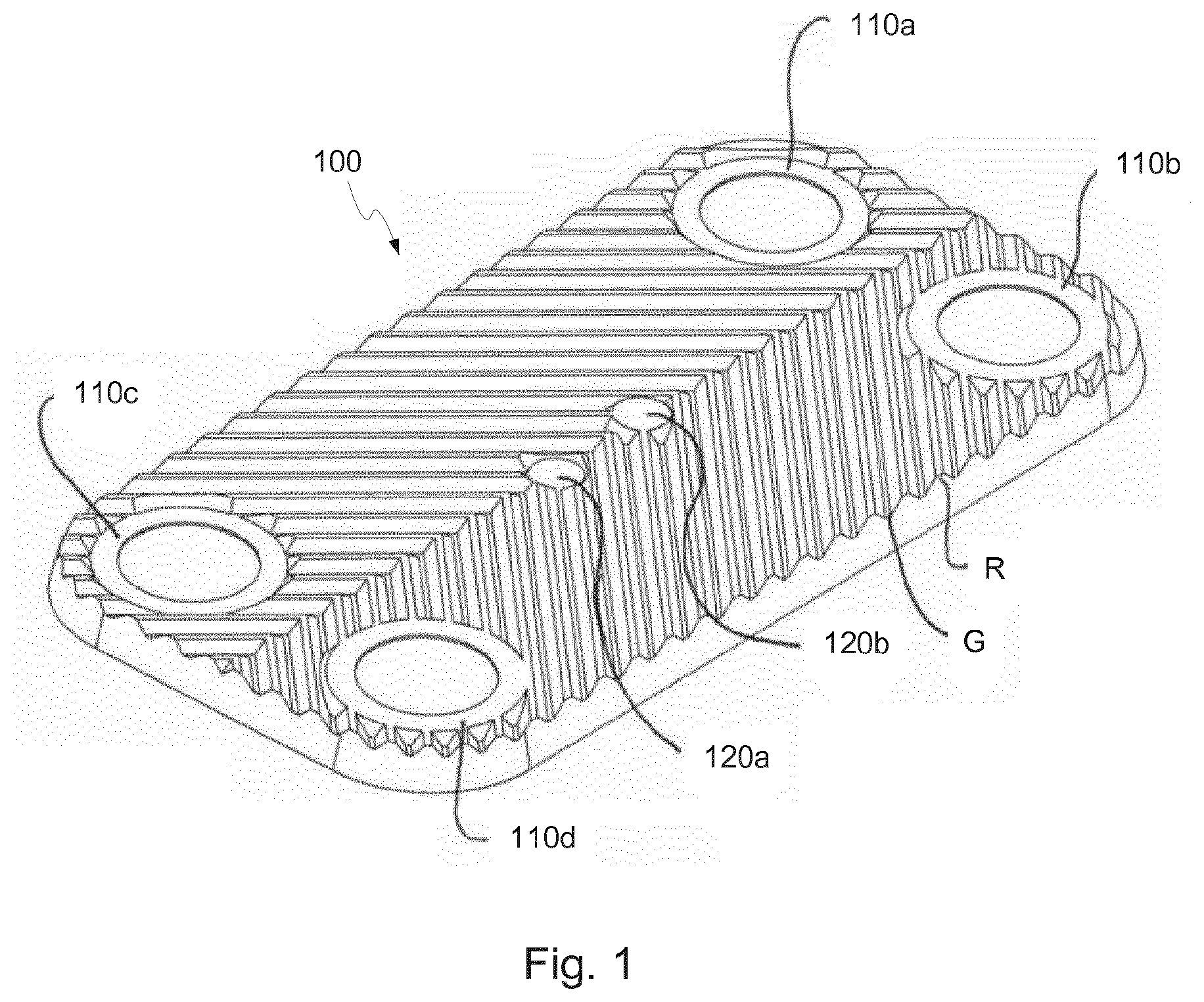
[0010] FIG. 1 is a perspective view of a heat exchanger plate comprised in a heat exchanger according to a first embodiment;
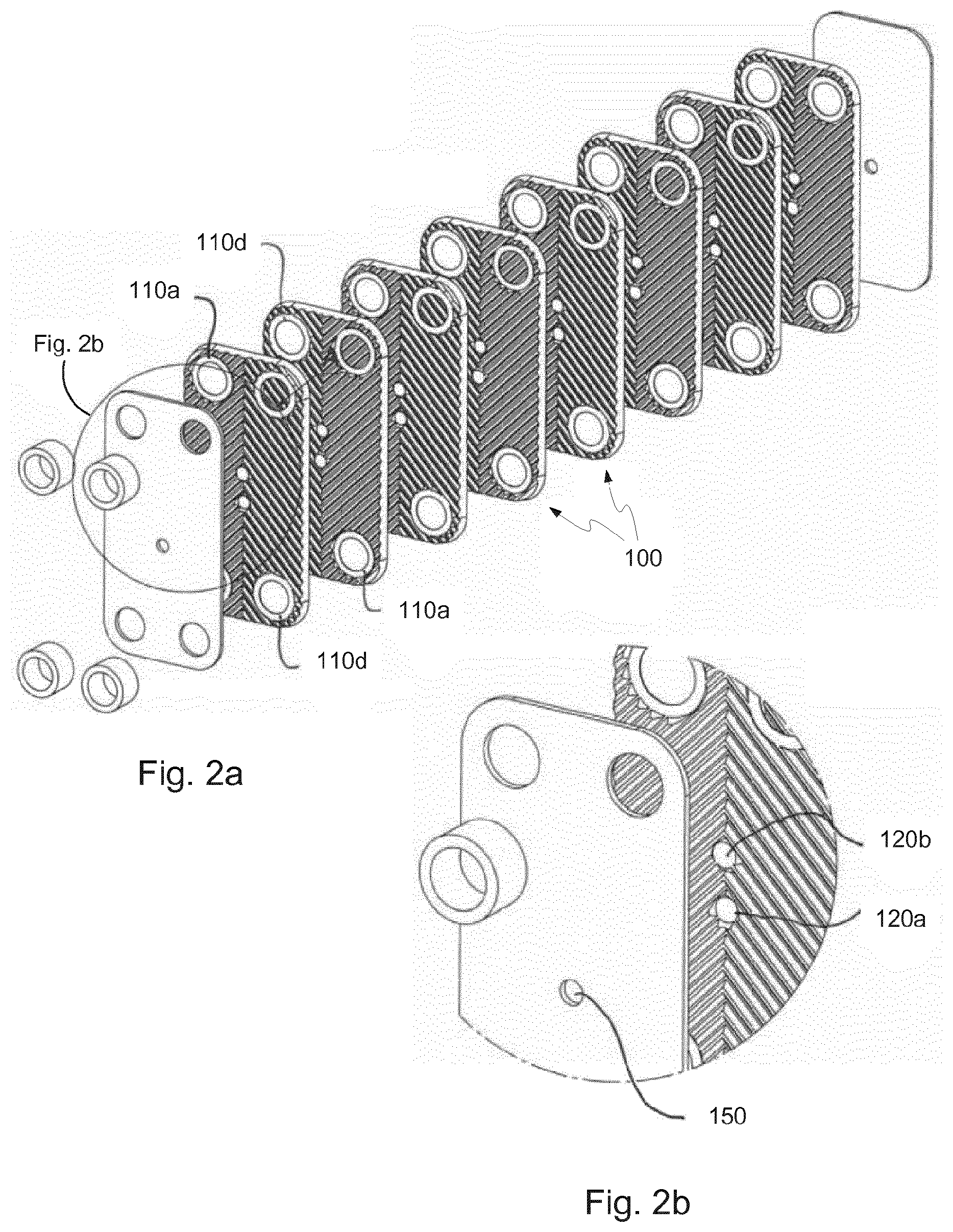
[0011] FIG. 2a is an exploded perspective view of a heat exchanger comprising eight heat exchanger plates according to FIG. 1;
[0012] FIG. 2 b is an enlarged view of a portion of FIG. 2a;
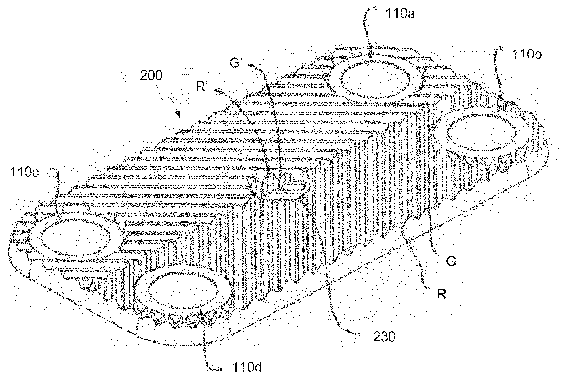
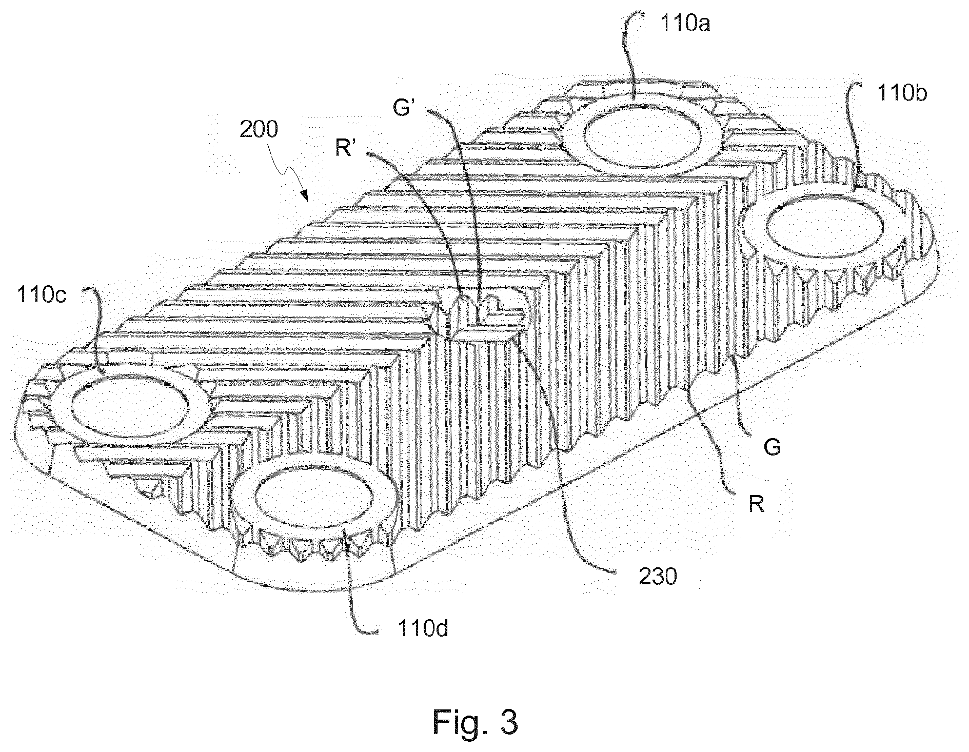
[0013] FIG. 3 is a perspective view of a heat exchanger plate comprised in a heat exchanger according to a second embodiment;
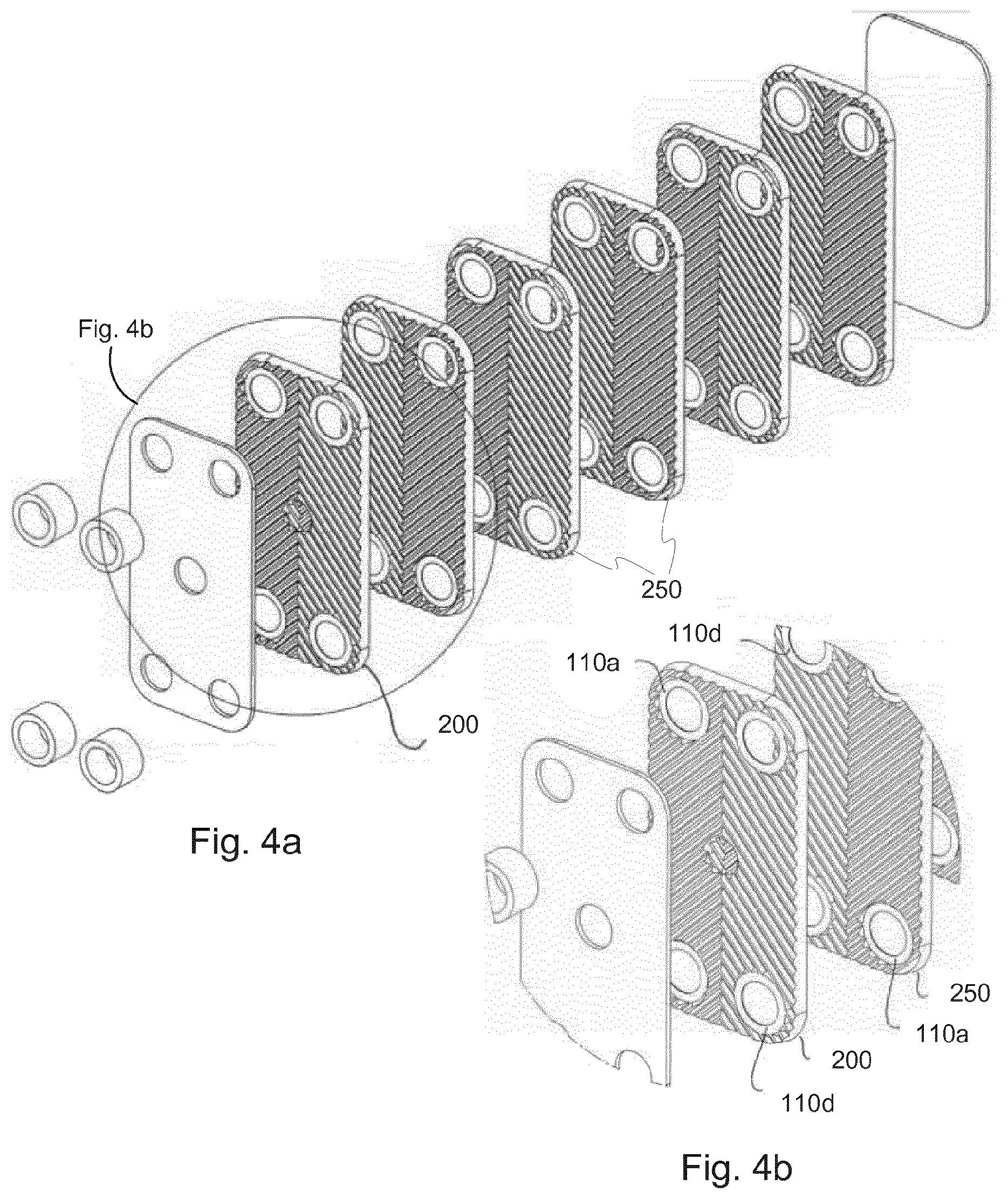
[0014] FIG. 4a is an exploded perspective view of a heat exchanger according to the second embodiment; and
[0015] FIG. 4b is a detail of the exploded perspective view of the heat exchanger according to the second embodiment shown in FIG. 4a.
DECRIPTION OF EMBODIMENTS
[0016] In FIGS. 1, 2a and 2b, a first embodiment is shown. With reference to FIG. 1, a heat exchanger plate 100 comprises four port openings 110a, 110b, 110c, 110d provided at different levels; the port openings 110a and 110c are provided at a low level and the port openings 110b and 110d are provided at a high level. Also, the heat exchanger plate 100 is provided with a pressed pattern of ridges R and grooves G, wherein the ridges R are provided at the same level as the port openings 110b and 110d and the grooves G are provided at the same level as the port openings 110a and 110c and wherein the pressed pattern is provided in a herringbone pattern. Moreover, the heat exchanger plate 100 comprises two plan areas 120a, 120b, located along a central axis extending along a length of the heat exchanger plate 100. The plan area 120a is provided at a low level, i.e. the same level as the grooves G and the port openings 110a, 110c and the plan area 120b is provided at a high level, i.e. the same level as the ridges R and the port openings 110b, 110d.
[0017] In order to form a heat exchanger from the heat exchanger plates, the heat exchanger plates are placed in a stack (shown exploded in FIG. 2a), wherein every other heat exchanger plate is turned 180 degrees around a central axis extending perpendicular to a plane of the heat exchanger plate. Due to every other plate being turned around the central axis, the herringbone patterns of neighboring plates will point in opposite directions; hence, contact points keeping neighboring plates on a distance from one another will be formed between the ridges and groves of the neighboring plates, hence forming interplate flow channels for media to exchange heat. Moreover, due to the port openings 110a, 110b, 110c and 110d being provided at different levels, there will be selective communication between the port openings and the interplate flow channels in a way well known by persons skilled in the art of plate heat exchangers.
[0018] In the same way as the port openings 110a-110d cooperate to form selective communication between the port openings and the interplate flow channels, the plan areas 120a and 120b will provide for selective contact with one another. If one for a moment imagines the plate shown in FIG. 1 as an end or start plate, i.e. an outer plate of the stack of heat exchanger plates, the plan portion 120a of such plate will contact the plan portion 120b of a neighboring plate.
[0019] Once assembled, the stack of heat exchanger plates is brazed to form a heat exchanger. During the brazing process, surfaces of neighboring plates contacting one another will be brazed together, and possible narrow gaps will be filled with brazing material. As well known by persons skilled in the art of brazing, a brazing material is generally a metal or an alloy having a slightly lower melting point than the material it is to join, i.e. the base material which the heat exchanger plates 100 are made from.
[0020] Metals and alloys are excellent heat conductors--hence, heat will be transferred from a flow channel via two adjoining plan portions--it is hence possible to measure a temperature of a medium of a flow channel inside the outer flow channel.
[0021] In another embodiment, either of two adjoining plan areas 120a, 120b may be provided with a central opening. This central opening serves to decrease the plate thickness of the combined plan areas 120a, 120b and hence provides for a more efficient heat transfer than if the heat must be transferred through two plate thicknesses and brazing material.
[0022] By fastening a temperature sensor on the plan area of an outer heat exchanger plate, the plan area of which being in contact with a plan area of a neighbouring plate, it is possible to measure the temperature of the medium flowing through a plate interspace delimited by the second and third heat exchanger plates counted from the outer ends of the stack of heat exchanger plates.
[0023] Moreover, in some cases, the heat exchanger may be provided with cover plates 130, 140, serving to increase the pressure handling capability of the heat exchanger. If such cover plates are arranged at the ends of the stack of heat exchanger plates, an opening 150 may be provided in order to provide access to the plan area 120a of the outermost heat exchanger plate 100.
[0024] In FIGS. 3-4b, a second embodiment is shown. In FIGS. 3, 4a and 4b, components identical to the components of the first embodiment have been given the same reference numerals also in the second embodiment. With reference to FIG. 3, a heat exchanger plate 200 comprised in a heat exchanger according to the second embodiment is shown. The heat exchanger plate 200 is identical to the heat exchanger plates 100 according to the first embodiment, except in that the plan areas 120a and 120b have been replaced by a recessed portion 230.
[0025] The recessed portion 230 is provided with a pressed pattern of ridges R' and grooves G' identical to the ridges R and grooves G of a neighboring plate and are adapted to snugly fit within the pressed pattern of its neighboring plate.
[0026] In contrast to the first embodiment, the heat exchanger plate 200 is the only plate of its kind comprised in a heat exchanger according to the second embodiment. All other heat exchanger plates comprised in the heat exchanger according to the second embodiment are "plain" heat exchanger plates 250, i.e. heat exchanger plates without both plan areas 120a, 120b and recessed portions 230. This is beneficial for the heat exchange performance of the heat exchanger, since, however minute, the heat exchange performance of the heat exchanger will be negatively influenced by both the plan areas 120a and 120b of the first embodiment and the recessed portion 230 of the second embodiment.
[0027] With reference to FIGS. 4a and 4b, the arrangement of the heat exchanger plate 200 and its neighbouring heat exchanger plate 250 when placed in a stack to form a heat exchanger according to the second embodiment is shown. As can be seen therein, the herringbone patterns of the heat exchanger plate 200 and its neighboring plate 250 point in opposite directions--hence, contact points keeping the plate on a distance from one another under formation of interplate flow channels will be formed. In the recessed portion 230, however, a herringbone pattern pointing in the opposite direction vis-a-vis the herringbone pattern of the heat exchanger plate 200 is arranged. Consequently, this herringbone pattern will point in the same direction as the herringbone pattern of the neighboring heat exchanger plate 250, and by adjusting the phase of the herringbone patterns of the heat exchanger plate 250 and the recessed portion 230, a snug fit between the patterns may be achieved.
[0028] By the snug fit between the patterns, an efficient heat transfer from a second flow channel, i.e. a flow channel formed by the heat exchanger plates 250 neighboring the heat exchanger plate 200, will be formed, and by fastening a temperature sensor to the recessed portion 230, a temperature of the medium flowing in the second flow channel may be measured accurately.
[0029] It should be noted that also this embodiment can be provided with a central opening in the recessed portion 230 in order to further increase the heat transfer from the second flow channel to the sensor.
* * * * *
D00000
D00001
D00002
D00003
D00004
XML
uspto.report is an independent third-party trademark research tool that is not affiliated, endorsed, or sponsored by the United States Patent and Trademark Office (USPTO) or any other governmental organization. The information provided by uspto.report is based on publicly available data at the time of writing and is intended for informational purposes only.
While we strive to provide accurate and up-to-date information, we do not guarantee the accuracy, completeness, reliability, or suitability of the information displayed on this site. The use of this site is at your own risk. Any reliance you place on such information is therefore strictly at your own risk.
All official trademark data, including owner information, should be verified by visiting the official USPTO website at www.uspto.gov. This site is not intended to replace professional legal advice and should not be used as a substitute for consulting with a legal professional who is knowledgeable about trademark law.